3GPP TS 36.133 V8.9 - 株式会社QT · LTE™ is a Trade Mark of ETSI currently being registered...
328
3GPP TS 36.133 V8.9.0 (2010-03) Technical Specification 3rd Generation Partnership Project; Technical Specification Group Radio Access Network; Evolved Universal Terrestrial Radio Access (E-UTRA); Requirements for support of radio resource management (Release 8) The present document has been developed within the 3 rd Generation Partnership Project (3GPP TM ) and may be further elaborated for the purposes of 3GPP. The present document has not been subject to any approval process by the 3GPP Organizational Partners and shall not be implemented. This Specification is provided for future development work within 3GPP only. The Organizational Partners accept no liability for any use of this Specification. Specifications and reports for implementation of the 3GPP TM system should be obtained via the 3GPP Organizational Partners' Publications Offices.
Transcript of 3GPP TS 36.133 V8.9 - 株式会社QT · LTE™ is a Trade Mark of ETSI currently being registered...
3GPP TS 36.133 V8.9.0 (2010-03)Technical Specification
3rd Generation Partnership Project;Technical Specification Group Radio Access Network;Evolved Universal Terrestrial Radio Access (E-UTRA);
Requirements for support of radio resource management(Release 8)
The present document has been developed within the 3rd Generation Partnership Project (3GPP TM) and may be further elaborated for the purposes of 3GPP. The present document has not been subject to any approval process by the 3GPP Organizational Partners and shall not be implemented. This Specification is provided for future development work within 3GPP only. The Organizational Partners accept no liability for any use of this Specification. Specifications and reports for implementation of the 3GPP TM system should be obtained via the 3GPP Organizational Partners' Publications Offices.
3GPP
2Release 8 3GPP TS 36.133 V8.9.0 (2010-03)
Keywords UMTS, radio
3GPP
Postal address
3GPP support office address 650 Route des Lucioles - Sophia Antipolis
Valbonne - FRANCE Tel.: +33 4 92 94 42 00 Fax: +33 4 93 65 47 16
Internet http://www.3gpp.org
Copyright Notification
No part may be reproduced except as authorized by written permission. The copyright and the foregoing restriction extend to reproduction in all media.
© 2010, 3GPP Organizational Partners (ARIB, ATIS, CCSA, ETSI, TTA, TTC).
All rights reserved. UMTS™ is a Trade Mark of ETSI registered for the benefit of its members 3GPP™ is a Trade Mark of ETSI registered for the benefit of its Members and of the 3GPP Organizational Partners LTE™ is a Trade Mark of ETSI currently being registered for the benefit of its Members and of the 3GPP Organizational Partners GSM® and the GSM logo are registered and owned by the GSM Association
3GPP
3Release 8 3GPP TS 36.133 V8.9.0 (2010-03)
Contents Foreword........................................................................................................................................................... 13 1 Scope ...................................................................................................................................................... 14 2 References .............................................................................................................................................. 14 3 Definitions, symbols and abbreviations ................................................................................................. 15 3.1 Definitions ....................................................................................................................................................... 15 3.2 Symbols ........................................................................................................................................................... 15 3.3 Abbreviations ................................................................................................................................................... 16 3.4 Test tolerances ................................................................................................................................................. 17 4 E-UTRAN RRC_IDLE state mobility ................................................................................................... 18 4.1 Cell Selection ................................................................................................................................................... 18 4.2 Cell Re-selection .............................................................................................................................................. 18 4.2.1 Introduction ................................................................................................................................................ 18 4.2.2 Requirements.............................................................................................................................................. 18 4.2.2.1 Measurement and evaluation of serving cell ........................................................................................ 18 4.2.2.2 Void ...................................................................................................................................................... 19 4.2.2.3 Measurements of intra-frequency E-UTRAN cells .............................................................................. 19 4.2.2.4 Measurements of inter-frequency E-UTRAN cells .............................................................................. 20 4.2.2.5 Measurements of inter-RAT cells ......................................................................................................... 21 4.2.2.5.1 Measurements of UTRAN FDD cells ............................................................................................ 21 4.2.2.5.2 Measurements of UTRAN TDD cells ............................................................................................ 22 4.2.2.5.3 Measurements of GSM cells .......................................................................................................... 23 4.2.2.5.4 Measurements of HRPD cells ........................................................................................................ 23 4.2.2.5.5 Measurements of cdma2000 1X .................................................................................................... 24 4.2.2.6 Evaluation of cell re-selection criteria .................................................................................................. 24 4.2.2.7 Maximum interruption in paging reception .......................................................................................... 24 4.2.2.8 void ....................................................................................................................................................... 25 4.2.2.9 UE measurement capability .................................................................................................................. 25 5 E-UTRAN RRC_CONNECTED state mobility .................................................................................... 25 5.1 E-UTRAN Handover ....................................................................................................................................... 26 5.1.1 Introduction ................................................................................................................................................ 26 5.1.2 Requirements.............................................................................................................................................. 26 5.1.2.1 E-UTRAN FDD – FDD ........................................................................................................................ 26 5.1.2.1.1 Handover delay ............................................................................................................................... 26 5.1.2.1.2 Interruption time ............................................................................................................................. 26 5.2.2.2 E-UTRAN FDD – TDD ....................................................................................................................... 27 5.2.2.2.1 (Void) .............................................................................................................................................. 27 5.2.2.2.2 (Void) .............................................................................................................................................. 27 5.2.2.3 E-UTRAN TDD – FDD ....................................................................................................................... 27 5.2.2.3.1 (Void) .............................................................................................................................................. 27 5.2.2.3.2 (Void) .............................................................................................................................................. 27 5.2.2.4 E-UTRAN TDD – TDD ....................................................................................................................... 27 5.2.2.4.1 Handover delay ..................................................................................................................................... 27 5.2.2.4.2 Interruption time ............................................................................................................................. 27 5.3 Handover to other RATs .................................................................................................................................. 28 5.3.1 E-UTRAN - UTRAN FDD Handover ........................................................................................................ 28 5.3.1.1 Introduction .......................................................................................................................................... 28 5.3.1.1.1 Handover delay ............................................................................................................................... 28 5.3.1.1.2 Interruption time ............................................................................................................................. 28 5.3.2 E-UTRAN - UTRAN TDD Handover ....................................................................................................... 29 5.3.2.1 Introduction .......................................................................................................................................... 29 5.3.2.2 Requirements ........................................................................................................................................ 29 5.3.2.2.1 Handover delay ............................................................................................................................... 29 5.3.2.2.2 Interruption time ............................................................................................................................. 29 5.3.3 E-UTRAN - GSM Handover ...................................................................................................................... 30
3GPP
4Release 8 3GPP TS 36.133 V8.9.0 (2010-03)
5.3.3.1 Introduction .......................................................................................................................................... 30 5.3.3.2 Requirements ........................................................................................................................................ 30 5.3.3.2.1 Handover delay ............................................................................................................................... 30 5.3.3.2.2 Interruption time ............................................................................................................................. 30 5.4 Handover to Non-3GPP RATs......................................................................................................................... 31 5.4.1 E-UTRAN – HRPD Handover ................................................................................................................... 31 5.4.1.1 Introduction ..................................................................................................................................... 31 5.4.1.1.1 Handover delay ............................................................................................................................... 31 5.4.1.1.2 Interruption time ............................................................................................................................. 31 5.4.2 E-UTRAN – cdma2000 1X Handover ....................................................................................................... 32 5.4.2.1 Introduction ..................................................................................................................................... 32 5.4.2.1.1 Handover delay ............................................................................................................................... 32 5.4.2.1.2 Interruption time ............................................................................................................................. 32 6 RRC Connection Mobility Control ........................................................................................................ 32 6.1 RRC Re-establishment ..................................................................................................................................... 32 6.1.1 Introduction .......................................................................................................................................... 32 6.1.2 Requirements ........................................................................................................................................ 33 6.1.2.1 UE Re-establishment delay requirement ......................................................................................... 33 6.2 Random Access ............................................................................................................................................... 33 6.2.1 Introduction ................................................................................................................................................ 33 6.2.2 Requirements.............................................................................................................................................. 33 6.2.2.1 Contention based random access .......................................................................................................... 34 6.2.2.1.1 Correct behaviour when receiving Random Access Response reception........................................ 34 6.2.2.1.2 Correct behaviour when not receiving Random Access Response reception ................................. 34 6.2.2.1.3 Correct behaviour when receiving a NACK on msg3 .......................................................................... 34 6.2.2.1.4 Void ................................................................................................................................................ 34 6.2.2.1.5 Correct behaviour when receiving a message over Temporary C-RNTI ........................................ 34 6.2.2.1.6 Correct behaviour when contention Resolution timer expires ........................................................ 34 6.2.2.2 Non-Contention based random access .................................................................................................. 34 6.2.2.2.1 Correct behaviour when receiving Random Access Response ....................................................... 34 6.2.2.2.2 Correct behaviour when not receiving Random Access Response ................................................. 34 7 Timing and signalling characteristics ..................................................................................................... 35 7.1 UE transmit timing .......................................................................................................................................... 35 7.1.1 Introduction ................................................................................................................................................ 35 7.1.2 Requirements.............................................................................................................................................. 35 7.2 UE timer accuracy ........................................................................................................................................... 36 7.2.1 Introduction ................................................................................................................................................ 36 7.2.2 Requirements.............................................................................................................................................. 36 7.3 Timing Advance .............................................................................................................................................. 36 7.3.1 Introduction ................................................................................................................................................ 36 7.3.2 Requirements.............................................................................................................................................. 36 7.3.2.1 Timing Advance adjustment delay ....................................................................................................... 36 7.3.2.2 Timing Advance adjustment accuracy .................................................................................................. 36 7.4 Cell phase synchronization accuracy (TDD) ................................................................................................... 36 7.4.1 Definition ................................................................................................................................................... 36 7.4.2 Minimum requirements .............................................................................................................................. 37 7.5 Synchronization Requirements for E-UTRAN to 1xRTT and HRPD Handovers ........................................... 37 7.5.1 Introduction ................................................................................................................................................ 37 7.5.2 eNodeB Synchronization Requirements..................................................................................................... 37 7.5.2.1 Synchronized E-UTRAN ...................................................................................................................... 37 7.5.2.2 Non-Synchronized E-UTRAN.............................................................................................................. 37 7.6 Radio Link Monitoring .................................................................................................................................... 38 7.6 .1 Introduction ................................................................................................................................................ 38 7.6.2 Requirements.............................................................................................................................................. 39 7.6.2.1 Minimum requirement when no DRX is used ...................................................................................... 39 7.6.2.2 Minimum requirement when DRX is used ........................................................................................... 39 7.6.2.3 Minimum requirement at transitions .................................................................................................... 40 8 UE Measurements Procedures in RRC_CONNECTED State ............................................................... 40 8.1 General Measurement Requirements ............................................................................................................... 40 8.1.1 Introduction ................................................................................................................................................ 40
3GPP
5Release 8 3GPP TS 36.133 V8.9.0 (2010-03)
8.1.2 Requirements.............................................................................................................................................. 41 8.1.2.1 UE measurement capability .................................................................................................................. 41 8.1.2.1.1 Monitoring of multiple layers using gaps ....................................................................................... 41 8.1.2.2 E-UTRAN intra frequency measurements ............................................................................................ 42 8.1.2.2.1 E-UTRAN FDD intra frequency measurements ............................................................................. 42 8.1.2.2.2 E-UTRAN TDD intra frequency measurements ............................................................................. 45 8.1.2.3 E-UTRAN inter frequency measurements ............................................................................................ 48 8.1.2.3.1 E-UTRAN FDD – FDD inter frequency measurements ................................................................. 48 8.1.2.3.2 E-UTRAN TDD – TDD inter frequency measurements ................................................................. 51 8.1.2.3.3 E-UTRAN TDD – FDD inter frequency measurements ................................................................. 54 8.1.2.3.4 E-UTRAN FDD – TDD inter frequency measurements ................................................................. 54 8.1.2.4 Inter RAT measurements ...................................................................................................................... 55 8.1.2.4.1 E-UTRAN FDD – UTRAN FDD measurements ............................................................................ 55 8.1.2.4.2 E-UTRAN TDD – UTRAN FDD measurements ........................................................................... 58 8.1.2.4.3 E-UTRAN TDD – UTRAN TDD measurements ........................................................................... 58 8.1.2.4.4 E-UTRAN FDD – UTRAN TDD measurements ........................................................................... 61 8.1.2.4.5 E-UTRAN FDD – GSM measurements .......................................................................................... 61 8.1.2.4.6 E-UTRAN TDD – GSM measurements ......................................................................................... 66 8.1.2.4.7 E-UTRAN FDD – UTRAN FDD measurements for SON ............................................................. 66 8.1.2.4.8 E-UTRAN TDD – UTRAN FDD measurements for SON ............................................................. 68 8.1.2.4.9 E-UTRAN FDD – cdma2000 1xRTT measurements ..................................................................... 68 8.1.2.4.9.1a E-UTRAN FDD – cdma2000 1xRTT measurements when no DRX is used ................................. 68 8.1.2.4.10 E-UTRAN TDD – cdma2000 1xRTT measurements ..................................................................... 68 8.1.2.4.11 E-UTRAN FDD – HRPD measurements ........................................................................................ 68 8.1.2.4.12 E-UTRAN TDD – HRPD measurements ....................................................................................... 68 8.1.2.4.13 E-UTRAN TDD – UTRAN TDD measurements for SON ............................................................. 69 8.1.2.4.14 E-UTRAN FDD – UTRAN TDD measurements for SON ............................................................. 70 8.2 Capabilities for Support of Event Triggering and Reporting Criteria .............................................................. 70 8.2.1 Introduction ................................................................................................................................................ 70 8.2.2 Requirements.............................................................................................................................................. 70 9 Measurements performance requirements for UE .................................................................................. 71 9.1 E-UTRAN measurements ................................................................................................................................ 71 9.1.2 Intra-frequency RSRP Accuracy Requirements ......................................................................................... 71 9.1.2.1 Absolute RSRP Accuracy ..................................................................................................................... 71 9.1.2.2 Relative Accuracy of RSRP ................................................................................................................. 72 9.1.3 Inter-frequency RSRP Accuracy Requirements ......................................................................................... 73 9.1.3.1 Absolute RSRP Accuracy ..................................................................................................................... 73 9.1.3.2 Relative Accuracy of RSRP ................................................................................................................. 73 9.1.4 RSRP Measurement Report Mapping ........................................................................................................ 74 9.1.5 Intra-frequency RSRQ Accuracy Requirements ........................................................................................ 74 9.1.5.1 Absolute RSRQ Accuracy .................................................................................................................... 74 9.1.6 Inter-frequency RSRQ Accuracy Requirements ........................................................................................ 75 9.1.6.1 Absolute RSRQ Accuracy .................................................................................................................... 75 9.1.6.2 Relative Accuracy of RSRQ ................................................................................................................. 76 9.1.7 RSRQ Measurement Report Mapping ....................................................................................................... 76 9.1.8 Power Headroom ........................................................................................................................................ 77 9.1.8.1 Period.................................................................................................................................................... 77 9.1.8.2 Reporting Delay .................................................................................................................................... 77 9.1.8.3 Void ...................................................................................................................................................... 77 9.1.8.4 Report Mapping .................................................................................................................................... 77 9.2 UTRAN FDD Measurements .......................................................................................................................... 77 9.2.1 UTRAN FDD CPICH RSCP ...................................................................................................................... 78 9.2.2 UTRAN FDD carrier RSSI ........................................................................................................................ 78 9.2.3 UTRAN FDD CPICH Ec/No ..................................................................................................................... 78 9.3 UTRAN TDD Measurements .......................................................................................................................... 79 9.3.1 UTRAN TDD P-CCPCH RSCP................................................................................................................. 79 9.3.2 UTRAN TDD carrier RSSI ........................................................................................................................ 79 9.3.3 Void ............................................................................................................................................................ 80 9.4 GSM Measurements ........................................................................................................................................ 80 9.4.1 GSM carrier RSSI ...................................................................................................................................... 80 9.5 CDMA2000 1x RTT Measurements ................................................................................................................ 80
3GPP
6Release 8 3GPP TS 36.133 V8.9.0 (2010-03)
9.5.1 CDMA2000 1x RTT Pilot Strength ........................................................................................................... 80 10 Measurements Performance Requirements for E-UTRAN .................................................................... 81 10.1 Received Interference Power ........................................................................................................................... 81 10.1.1 Absolute accuracy requirement .................................................................................................................. 81 10.1.2 Relative accuracy requirement ................................................................................................................... 81 10.1.3 Received Interference Power measurement report mapping ...................................................................... 81 A.1 Purpose of annex .................................................................................................................................... 82 A.2 Requirement classification for statistical testing .................................................................................... 82 A.2.1 Types of requirements in TS 36.133 ................................................................................................................ 82 A.2.1.1 Time and delay requirements on UE higher layer actions .......................................................................... 82 A.2.1.2 Measurements of power levels, relative powers and time .......................................................................... 83 A.2.1.3 Implementation requirements ..................................................................................................................... 83 A.2.1.4 Physical layer timing requirements ............................................................................................................ 83 A.3 RRM test configurations ........................................................................................................................ 84 A.3.1 Reference Measurement Channels ................................................................................................................... 84 A.3.1.1 PDSCH ....................................................................................................................................................... 84 A.3.1.1.1 FDD ...................................................................................................................................................... 84 A.3.1.1.2 TDD ...................................................................................................................................................... 85 A.3.1.2 PCFICH/PDCCH/PHICH .......................................................................................................................... 86 A.3.1.2.1 FDD ...................................................................................................................................................... 86 A.3.1.2.2 TDD ...................................................................................................................................................... 86 A.3.2 OFDMA Channel Noise Generator (OCNG) .................................................................................................. 87 A.3.2.1 OCNG Patterns for FDD ............................................................................................................................ 87 A.3.2.1.1 OCNG FDD pattern 1: outer resource blocks allocation in 10 MHz .................................................... 87 A.3.2.1.2 OCNG FDD pattern 2: full bandwidth allocation in 10 MHz............................................................... 88 A.3.2.1.3 OCNG FDD pattern 3: outer resource blocks allocation in 1.4 MHz ................................................... 89 A.3.2.1.4 OCNG FDD pattern 4: full bandwidth allocation in 1.4 MHz .............................................................. 90 A.3.2.2 OCNG Patterns for TDD ............................................................................................................................ 91 A.3.2.2.1 OCNG TDD pattern 1: outer resource blocks allocation in 10 MHz .................................................... 91 A.3.2.2.2 OCNG TDD pattern 2: full bandwidth allocation in 10 MHz .............................................................. 93 A.3.2.2.3 OCNG TDD pattern 3: outer resource blocks allocation in 1.4 MHz ................................................... 94 A.3.2.2.4 OCNG TDD pattern 4: full bandwidth allocation in 1.4 MHz ............................................................. 94 A.3.3 Reference DRX Configurations ................................................................................................................. 95 A.4 E-UTRAN RRC_IDLE state .................................................................................................................. 95 A.4.2 Cell Re-Selection ...................................................................................................................................... 95 A.4.2.1 E-UTRAN FDD – FDD Intra frequency case....................................................................................... 95 A.4.2.1.1 Test Purpose and Environment ............................................................................................................. 95 A.4.2.1.2 Test Requirements ................................................................................................................................ 97 A.4.2.2 E-UTRAN TDD – TDD Intra frequency case ...................................................................................... 98 A.4.2.2.1 Test Purpose and Environment ............................................................................................................. 98 A.4.2.2.2 Test Requirements ................................................................................................................................ 99 A.4.2.3 E-UTRAN FDD – FDD Inter frequency case..................................................................................... 100 A.4.2.3.1 Test Purpose and Environment ........................................................................................................... 100 A.4.2.3.2 Test Requirements .............................................................................................................................. 101 A.4.2.4 E-UTRAN FDD – TDD Inter frequency case .................................................................................... 102 A.4.2.5 E-UTRAN TDD – FDD Inter frequency case .................................................................................... 102 A.4.2.6 E-UTRAN TDD – TDD: Inter frequency case ................................................................................... 102 A.4.2.6.1 Test Purpose and Environment ........................................................................................................... 102 A.4.2.6.2 Test Requirements .............................................................................................................................. 104 A.4.3 E-UTRAN to UTRAN Cell Re-Selection ...................................................................................................... 104 A.4.3.1 E-UTRAN FDD – UTRAN FDD:............................................................................................................ 105 A.4.3.1.1 EUTRA FDD-UTRA FDD cell reselection: UTRA FDD is of higher priority .................................. 105 A.4.3.1.1.1 Test Purpose and Environment ..................................................................................................... 105 A.4.3.1.1.2 Test Requirements ........................................................................................................................ 107 A.4.3.1.2 EUTRA FDD-UTRA FDD cell reselection: UTRA FDD is of lower priority ................................... 107 A.4.3.1.2.1 Test Purpose and Environment ..................................................................................................... 107 A.4.3.1.2.2 Test Requirements ........................................................................................................................ 109 A.4.3.1.3 EUTRA FDD-UTRA FDD cell reselection in fading propagation conditions: UTRA FDD is of
lower priority ...................................................................................................................................... 110
3GPP
7Release 8 3GPP TS 36.133 V8.9.0 (2010-03)
A.4.3.1.3.1 Test Purpose and Environment ..................................................................................................... 110 A.4.3.1.3.2 Test Requirements ........................................................................................................................ 112 A.4.3.2 E-UTRAN FDD – UTRAN TDD: ........................................................................................................... 113 A.4.3.2.1 Test Purpose and Environment ........................................................................................................... 113 A.4.3.2.1.1 3.84Mcps TDD option .................................................................................................................. 113 A.4.3.2.1.2 1.28Mcps TDD option .................................................................................................................. 113 A.4.3.2.1.3 7.68Mcps TDD option .................................................................................................................. 115 A.4.3.2.1 Test Requirements .............................................................................................................................. 115 A.4.3.2.1.1 3.84Mcps TDD option .................................................................................................................. 115 A.4.3.2.1.2 1.28Mcps TDD option .................................................................................................................. 115 A.4.3.2.2.2.3 7.68Mcps TDD option ............................................................................................................. 115 A.4.3.3 E-UTRAN TDD – UTRAN FDD: ...................................................................................................... 116 A.4.3.3.1 Test Purpose and Environment ........................................................................................................... 116 A.4.3.3.2 Test Requirements .............................................................................................................................. 117 A.4.3.4 E-UTRAN TDD – UTRAN TDD: ........................................................................................................... 118 A.4.3.4.1 E-UTRA to UTRA TDD cell re-selection: UTRA is of higher priority ............................................. 118 A.4.3.4.1.1 Test Purpose and Environment ..................................................................................................... 118 A.4.3.4.1.1.1 3.84 Mcps TDD option ............................................................................................................ 118 A.4.3.4.1.1.2 1.28 Mcps TDD option ............................................................................................................ 118 A.4.3.4.1.1.3 7.68 Mcps TDD option ............................................................................................................ 120 A.4.3.4.1.2 Test Requirements ........................................................................................................................ 120 A.4.3.4.1.2.1 3.84 Mpcs TDD option ............................................................................................................ 120 A.4.3.4.1.2.2 1.28 Mpcs TDD option ............................................................................................................ 120 A.4.3.4.2 E-UTRA to UTRA TDD cell re-selection: UTRA is of lower priority .............................................. 121 A.4.3.4.2.1 Test Purpose and Environment ..................................................................................................... 121 A.4.3.4.2.1.1 3.84 Mcps TDD option ............................................................................................................ 121 A.4.3.4.2.1.2 1.28 Mcps TDD option ............................................................................................................ 121 A.4.3.4.2.1.3 7.68 Mcps TDD option ............................................................................................................ 123 A.4.3.4.2.2 Test Requirements ........................................................................................................................ 123 A.4.3.4.2.2.1 3.84 Mpcs TDD option ............................................................................................................ 123 A.4.3.4.2.2.2 1.28 Mpcs TDD option ............................................................................................................ 123 A.4.3.4.2.2.3 7.68 Mpcs TDD option ............................................................................................................ 123 A.4.4 E-UTRAN to GSM Cell Re-Selection ........................................................................................................... 124 A.4.4.1 E-UTRAN FDD – GSM: .......................................................................................................................... 124 A.4.4.1.1 Test Purpose and Environment ..................................................................................................................... 124 A.4.4.1.2 Test Requirements .............................................................................................................................. 126 A.4.4.2 E-UTRAN TDD – GSM: .................................................................................................................... 126 A.4.4.2.1 Test Purpose and Environment ........................................................................................................... 126 A.4.4.2.2 Test Requirements .............................................................................................................................. 128 A.4.5 E-UTRAN to HRPD Cell Re-Selection ......................................................................................................... 129 A.4.5.1 E-UTRAN FDD – HRPD ......................................................................................................................... 129 A.4.5.1.1 E-UTRAN FDD – HRPD Cell Reselection: HRPD is of Lower Priority ........................................... 129 A.4.5.1.1.1 Test Purpose and Environment ..................................................................................................... 129 A.4.5.1.1.2 Test Requirements .............................................................................................................................. 131 A.4.6 E-UTRAN to cdma2000 1X Cell Re-Selection ........................................................................................ 131 A.4.6.1 E-UTRAN FDD – cdma2000 1X ....................................................................................................... 131 A.4.6.1.1 E-UTRAN FDD – cdma2000 1X Cell Reselection: cdma2000 1X is of Lower Priority ................... 131 A.4.6.1.1.1 Test Purpose and Environment ........................................................................................................... 131 A.4.6.1.1.2 Test Requirements .............................................................................................................................. 134 A.5 E-UTRAN RRC CONNECTED Mode Mobility ................................................................................. 134 A.5.1 E-UTRAN Handover ..................................................................................................................................... 134 A.5.1.1 E-UTRAN FDD - FDD Intra frequency handover ................................................................................... 134 A.5.1.1.1 Test Purpose and Environment................................................................................................................. 134 A.5.1.1.2 Test Requirements .................................................................................................................................... 136 A.5.1.2 E-UTRAN TDD - TDD Intra frequency handover ........................................................................................ 136 A.5.1.2.1 Test Purpose and Environment................................................................................................................. 136 A.5.1.2.2 Test Requirements .................................................................................................................................... 138 A.5.1.3 E-UTRAN FDD – FDD Inter frequency handover ........................................................................................ 138 A.5.1.3.1 Test Purpose and Environment................................................................................................................. 138 A.5.1.3.2 Test Requirements .................................................................................................................................... 140 A.5.1.4 E-UTRAN TDD – TDD Inter frequency handover ....................................................................................... 140
3GPP
8Release 8 3GPP TS 36.133 V8.9.0 (2010-03)
A.5.1.4.1 Test Purpose and Environment................................................................................................................. 140 A.5.1.4.2 Test Requirements .............................................................................................................................. 143 A.5.1.5 E-UTRAN FDD – FDD Inter frequency handover: unknown target cell ................................................. 143 A.5.1.5.1 Test Purpose and Environment ........................................................................................................... 143 A.5.1.5.2 Test Requirements .................................................................................................................................... 145 A.5.1.6 E-UTRAN TDD – TDD Inter frequency handover; unknown Target Cell .............................................. 146 A.5.1.6.1 Test Purpose and Environment ........................................................................................................... 146 A.5.1.6.2 Test Requirements .............................................................................................................................. 147 A.5.2 E-UTRAN Handover to other RATs ............................................................................................................. 148 A.5.2.1 E-UTRAN FDD – UTRAN FDD Handover ............................................................................................ 148 A.5.2.1.1 Test Purpose and Environment ........................................................................................................... 148 A.5.2.1.2 Test Requirements .............................................................................................................................. 149 A.5.2.2 E-UTRAN TDD - UTRAN FDD Handover ............................................................................................ 150 A.5.2.2.1 Test Purpose and Environment ........................................................................................................... 150 A.5.2.2.2 Test Requirements .............................................................................................................................. 153 A.5.2.3 E-UTRAN FDD- GSM Handover ..................................................................................................................... 153 A.5.2.3.1 Test Purpose and Environment ..................................................................................................... 153 A.5.2.3.2 Test Requirements ........................................................................................................................ 155 A.5.2.4 E-UTRAN TDD - UTRAN TDD Handover ............................................................................................ 155 A.5.2.4.1 Test Purpose and Environment ........................................................................................................... 155 A.5.2.4.1.1 3.84 Mcps TDD option ................................................................................................................. 155 A.5.2.4.1.2 1.28 Mcps TDD option ................................................................................................................. 155 A.5.2.4.1.3 7.68 Mcps TDD option ................................................................................................................. 157 A.5.2.4.2 Test Requirements .............................................................................................................................. 157 A.5.2.4.2.1 3.84 Mcps TDD option ................................................................................................................. 157 A.5.2.4.2.2 1.28 Mcps TDD option ................................................................................................................. 157 A.5.2.4.2.3 7.68 Mcps TDD option ................................................................................................................. 157 A.5.2.5 E-UTRAN FDD – UTRAN TDD Handover ............................................................................................ 158 A.5.2.5.1 Test Purpose and Environment ........................................................................................................... 158 A.5.2.5.1.1 3.84 Mcps TDD option ............................................................................................................ 158 A.5.2.5.1.2 1.28 Mcps TDD option ............................................................................................................ 158 A.5.2.5.1.3 7.68 Mcps TDD option ................................................................................................................. 160 A.5.2.5.2 Test Requirements .............................................................................................................................. 160 A.5.2.5.2.1 3.84 Mcps TDD option ................................................................................................................. 160 A.5.2.5.2.2 1.28 Mcps TDD option ................................................................................................................. 160 A.5.2.5.2.3 7.68 Mcps TDD option ................................................................................................................. 160 A.5.2.6 E-UTRAN TDD - GSM Handover ..................................................................................................... 160 A.5.2.6.1 Test Purpose and Environment ..................................................................................................... 160 A.5.2.6.2 Test Requirements ........................................................................................................................ 162 A.5.2.7 E-UTRAN FDD – UTRAN FDD Handover; Unknown Target Cell ....................................................... 163 A.5.2.7.1 Test Purpose and Environment ........................................................................................................... 163 A.5.2.7.2 Test Requirements .............................................................................................................................. 165 A.5.2.8 E-UTRAN FDD - GSM Handover; Unknown Target Cell ................................................................................ 165 A.5.2.8.1 Test Purpose and Environment ........................................................................................................... 165 A.5.2.8.2 Test Requirements .............................................................................................................................. 167 A.5.2.9 E-UTRAN TDD - GSM Handover; Unknown Target Cell ............................................................................... 168 A.5.2.9.1 Test Purpose and Environment ........................................................................................................... 168 A.5.2.9.2 Test Requirements .............................................................................................................................. 169 A.5.2.10 E-UTRAN TDD to UTRAN TDD handover: unknown target cell .......................................................... 170 A.5.2.10.1 Test Purpose and Environment ........................................................................................................... 170 A.5.2.10.2 Test Requirements .............................................................................................................................. 172 A.5.3 E-UTRAN Handover to Non-3GPP RATs ......................................................................................... 172 A.5.3.1 E-UTRAN FDD – HRPD Handover .................................................................................................. 172 A.5.3.1.1 Test Purpose and Environment ........................................................................................................... 172 A.5.3.1.2 Test Requirements .............................................................................................................................. 175 A.5.3.2 E-UTRAN FDD – cdma2000 1X Handover ....................................................................................... 175 A.5.3.2.1 Test Purpose and Environment ........................................................................................................... 175 A.5.3.2.2 Test Requirements .............................................................................................................................. 178 A.5.3.3 E-UTRAN FDD – HRPD Handover; Unknown Target Cell ................................................................... 178 A.5.3.3.1 Test Purpose and Environment ........................................................................................................... 178 A.5.3.3.2 Test Requirements .............................................................................................................................. 181 A.5.3.4 E-UTRAN FDD – cdma2000 1X Handover; Unknown Target cell ........................................................ 181
3GPP
9Release 8 3GPP TS 36.133 V8.9.0 (2010-03)
A.5.3.4.1 Test Purpose and Environment ........................................................................................................... 181 A.5.3.4.2 Test Requirements .............................................................................................................................. 184 A.6 RRC Connection Control ..................................................................................................................... 184 A.6.1 RRC Re-establishment ................................................................................................................................... 184 A.6.1.1 E-UTRAN FDD Intra-frequency RRC Re-establishment ........................................................................ 184 A.6.1.1.1 Test Purpose and Environment ........................................................................................................... 184 A.6.1.1.2 Test Requirements .............................................................................................................................. 186 A.6.1.2 E-UTRAN FDD Inter-frequency RRC Re-establishment ........................................................................ 186 A.6.1.2.1 Test Purpose and Environment ........................................................................................................... 186 A.6.1.2.2 Test Requirements .............................................................................................................................. 188 A.6.1.3 E-UTRAN TDD Intra-frequency RRC Re-establishment ........................................................................ 189 A.6.1.3.1 Test Purpose and Environment ........................................................................................................... 189 A.6.1.3.2 Test Requirements .............................................................................................................................. 190 A.6.1.4 E-UTRAN TDD Inter-frequency RRC Re-establishment ........................................................................ 191 A.6.1.4.1 Test Purpose and Environment ........................................................................................................... 191 A.6.1.4.2 Test Requirements .............................................................................................................................. 192 A.6.2 Random Access .................................................................................................................................. 193 A.6.2.1 E-UTRAN FDD – Contention Based Random Access Test ............................................................... 193 A.6.2.1.1 Test Purpose and Environment ........................................................................................................... 193 A.6.2.1.2.1 Random Access Response Reception ................................................................................................. 195 A.6.2.1.2.2 No Random Access Response Reception ........................................................................................... 195 A.6.2.1.2.3 Receiving a NACK on msg3 .............................................................................................................. 195 A.6.2.1.2.4 Reception of an Incorrect Message over Temporary C-RNTI ...................................................... 196 A.6.2.1.2.5 Reception of a Correct Message over Temporary C-RNTI........................................................... 196 A.6.2.1.2.6 Contention Resolution Timer expiry ............................................................................................. 196 A.6.2.2 E-UTRAN FDD – Non-Contention Based Random Access Test ....................................................... 196 A.6.2.2.1 Test Purpose and Environment ........................................................................................................... 196 A.6.2.2.2.1 Random Access Response Reception ................................................................................................. 198 A.6.2.2.2.2 No Random Access Response Reception ........................................................................................... 198 A.6.2.3 E-UTRAN TDD – Contention Based Random Access Test............................................................... 198 A.6.2.3.1 Test Purpose and Environment ........................................................................................................... 198 A.6.2.3.2.1 Random Access Response Reception ................................................................................................. 200 A.6.2.3.2.2 No Random Access Response reception ............................................................................................ 200 A.6.2.3.2.3 Receiving a NACK on msg3 .............................................................................................................. 200 A.6.2.3.2.4 Reception of an Incorrect Message over Temporary C-RNTI ...................................................... 201 A.6.2.3.2.5 Reception of a Correct Message over Temporary C-RNTI........................................................... 201 A.6.2.3.2.6 Contention Resolution Timer expiry ............................................................................................. 201 A.6.2.4 E-UTRAN TDD – Non-Contention Based Random Access Test ...................................................... 201 A.6.2.4.1 Test Purpose and Environment ........................................................................................................... 201 A.6.2.4.2.1 Random Access Response Reception ................................................................................................. 203 A.6.2.4.2.2 No Random Access Response Reception ........................................................................................... 203 A.7 Timing and Signalling Characteristics ................................................................................................. 203 A.7.1 UE Transmit Timing ...................................................................................................................................... 203 A.7.1.1 E-UTRAN FDD – UE Transmit Timing Accuracy Tests ........................................................................ 203 A.7.1.1.1 Test Purpose and Environment ........................................................................................................... 203 A.7.1.1.2 Test Requirements .............................................................................................................................. 205 A.7.1.2 E-UTRAN TDD - UE Transmit Timing Accuracy Tests ................................................................... 206 A.7.1.2.1 Test Purpose and Environment ........................................................................................................... 206 A.7.1.2.2 Test Requirements .............................................................................................................................. 208 A.7.2 UE Timing Advance ........................................................................................................................... 210 A.7.2.1 E-UTRAN FDD – UE Timing Advance Adjustment Accuracy Test ................................................. 210 A.7.2.1.1 Test Purpose and Environment ........................................................................................................... 210 A.7.2.1.2 Test Requirements .............................................................................................................................. 211 A.7.2.2 E-UTRAN TDD – UE Timing Advance Adjustment Accuracy Test ................................................. 212 A.7.2.2.1 Test Purpose and Environment ........................................................................................................... 212 A.7.2.2.2 Test Requirements .............................................................................................................................. 214 A.7.3 Radio Link Monitoring .................................................................................................................................. 214 A.7.3.1 E-UTRAN FDD Radio Link Monitoring Test for Out-of-sync ................................................................ 214 A.7.3.1.1 Test Purpose and Environment ........................................................................................................... 214 A.7.3.1.2 Test Requirements .............................................................................................................................. 218
3GPP
10Release 8 3GPP TS 36.133 V8.9.0 (2010-03)
A.7.3.2 E-UTRAN FDD Radio Link Monitoring Test for In-sync ....................................................................... 218 A.7.3.2.1 Test Purpose and Environment ........................................................................................................... 218 A.7.3.2.2 Test Requirements .............................................................................................................................. 221 A.7.3.3 E-UTRAN TDD Radio Link Monitoring Test for Out-of-sync ............................................................... 221 A.7.3.3.1 Test Purpose and Environment ........................................................................................................... 221 A.7.3.3.2 Test Requirements .............................................................................................................................. 225 A.7.3.4 E-UTRAN TDD Radio Link Monitoring Test for In-sync ....................................................................... 225 A.7.3.4.1 Test Purpose and Environment ........................................................................................................... 225 A.7.3.4.2 Test Requirements .............................................................................................................................. 228 A.7.3.5 E-UTRAN FDD Radio Link Monitoring Test for Out-of-sync in DRX .................................................. 228 A.7.3.5.1 Test Purpose and Environment ........................................................................................................... 228 A.7.3.5.2 Test Requirements .............................................................................................................................. 231 A.7.3.6 E-UTRAN FDD Radio Link Monitoring Test for In-sync in DRX ......................................................... 232 A.7.3.6.1 Test Purpose and Environment ........................................................................................................... 232 A.7.3.6.2 Test Requirements .............................................................................................................................. 234 A.7.3.7 E-UTRAN TDD Radio Link Monitoring Test for Out-of-sync in DRX .................................................. 234 A.7.3.7.1 Test Purpose and Environment ........................................................................................................... 234 A.7.3.7.2 Test Requirements .............................................................................................................................. 237 A.7.3.8 E-UTRAN TDD Radio Link Monitoring Test for In-sync in DRX .................................................... 238 A.7.3.8.1 Test Purpose and Environment ........................................................................................................... 238 A.7.3.8.2 Test Requirements .............................................................................................................................. 240 A.8 UE Measurements Procedures ............................................................................................................. 240 A.8.1 E-UTRAN FDD Intra-frequency Measurements ..................................................................................... 240 A.8.1.1 E-UTRAN FDD-FDD intra-frequency event triggered reporting under fading propagation conditions
in asynchronous cells ............................................................................................................................... 240 A.8.1.1.1 Test Purpose and Environment ........................................................................................................... 240 A.8.1.1.2 Test Requirements .............................................................................................................................. 242 A.8.1.2 E-UTRAN FDD-FDD intra-frequency event triggered reporting under fading propagation conditions
in synchronous cells ................................................................................................................................. 242 A.8.1.2.1 Test Purpose and Environment ........................................................................................................... 242 A.8.1.2.2 Test Requirements .............................................................................................................................. 244 A.8.1.3 E-UTRAN FDD-FDD intra-frequency event triggered reporting under fading propagation conditions
in synchronous cells with DRX ................................................................................................................ 244 A.8.1.3.1 Test Purpose and Environment ........................................................................................................... 244 A.8.1.3.2 Test Requirements .............................................................................................................................. 247 A.8.1.4 E-UTRAN FDD-FDD inter-frequency event triggered reporting under AWGN propagation
conditions in asynchronous cells with DRX when L3 filtering is used .................................................... 247 A.8.1.4.1 Test Purpose and Environment ........................................................................................................... 247 A.8.1.4.2 Test Requirements .............................................................................................................................. 250 A.8.2 E-UTRAN TDD Intra-frequency Measurements ..................................................................................... 250 A.8.2.1 E-UTRAN TDD-TDD intra-frequency event triggered reporting under fading propagation
conditions in synchronous cells ................................................................................................................ 250 A.8.2.1.1 Test Purpose and Environment ........................................................................................................... 250 A.8.2.1.2 Test Requirements .............................................................................................................................. 252 A.8.2.2 E-UTRAN TDD-TDD intra-frequency event triggered reporting under fading propagation
conditions in synchronous cells with DRX .............................................................................................. 252 A.8.2.2.1 Test Purpose and Environment ........................................................................................................... 252 A.8.2.2.2 Test Requirements .............................................................................................................................. 255 A.8.3 E-UTRAN FDD - FDD Inter-frequency Measurements .......................................................................... 255 A.8.3.1 E-UTRAN FDD-FDD Inter-frequency event triggered reporting under fading propagation conditions
in asynchronous cells ............................................................................................................................... 255 A.8.3.1.1 Test Purpose and Environment ........................................................................................................... 255 A.8.3.1.2 Test Requirements .............................................................................................................................. 257 A.8.3.2 E-UTRAN FDD-FDD Inter-frequency event triggered reporting when DRX is used under fading
propagation conditions in asynchronous cells .......................................................................................... 257 A.8.3.2.1 Test Purpose and Environment ........................................................................................................... 257 A.8.3.2.2 Test Requirements .............................................................................................................................. 260 A.8.4 E-UTRAN TDD - TDD Inter-frequency Measurements .......................................................................... 260 A.8.4.1 E-UTRAN TDD-TDD Inter-frequency event triggered reporting under fading propagation
conditions in synchronous cells ................................................................................................................ 260 A.8.4.1.1 Test Purpose and Environment ........................................................................................................... 260
3GPP
11Release 8 3GPP TS 36.133 V8.9.0 (2010-03)
A.8.4.1.2 Test Requirements .............................................................................................................................. 262 A.8.4.2 E-UTRAN TDD-TDD Inter-frequency event triggered reporting when DRX is used under fading
propagation conditions in synchronous cells ............................................................................................ 262 A.8.4.2.1 Test Purpose and Environment ........................................................................................................... 262 A.8.4.2.2 Test Requirements .............................................................................................................................. 265 A.8.5 E-UTRAN FDD - UTRAN FDD Measurements ........................................................................................... 265 A.8.5.1 E-UTRAN FDD - UTRAN FDD event triggered reporting under fading propagation conditions .......... 265 A.8.5.1.1 Test Purpose and Environment ........................................................................................................... 265 A.8.5.1.2 Test Requirements .............................................................................................................................. 268 A.8.5.2 E-UTRAN FDD - UTRAN FDD SON ANR cell search reporting under AWGN propagation
conditions ................................................................................................................................................. 268 A.8.5.2.1 Test Purpose and Environment ........................................................................................................... 268 A.8.5.2.2 Test Requirements .............................................................................................................................. 270 A.8.5.3 E-UTRAN FDD-UTRAN FDD event triggered reporting when DRX is used under fading
propagation conditions ............................................................................................................................. 270 A.8.5.3.1 Test Purpose and Environment ........................................................................................................... 270 A.8.5.3.2 Test Requirements .............................................................................................................................. 273 A.8.6 E-UTRAN TDD - UTRAN FDD Measurements ........................................................................................... 273 A.8.6.1 E-UTRAN TDD - UTRAN FDD event triggered reporting under fading propagation conditions .......... 273 A.8.6.1.1 Test Purpose and Environment ........................................................................................................... 273 A.8.6.1.2 Test Requirements .............................................................................................................................. 276 A.8.7 E-UTRAN TDD – UTRAN TDD Measurements .......................................................................................... 276 A.8.7.1 E-UTRAN TDD to UTRAN TDD cell search under fading propagation conditions ............................... 276 A.8.7.1.1 Test Purpose and Environment ........................................................................................................... 276 A.8.7.1.1.1 3.84 Mcps TDD option ................................................................................................................. 276 A.8.7.1.1.2 1.28 Mcps TDD option ................................................................................................................. 276 A.8.7.1.1.3 7.68 Mcps TDD option ................................................................................................................. 278 A.8.7.1.2 Test Requirements .............................................................................................................................. 278 A.8.7.1.2.1 3.84 Mcps TDD option ................................................................................................................. 278 A.8.7.1.2.2 1.28 Mcps TDD option ................................................................................................................. 278 A.8.7.1.2.3 7.68 Mcps TDD option ................................................................................................................. 278 A.8.7.2 E-UTRAN TDD-UTRAN TDD cell search when DRX is used under fading propagation conditions.... 278 A.8.7.2.1 Test Purpose and Environment ........................................................................................................... 278 A.8.7.2.2 Test Requirements .............................................................................................................................. 281 A.8.7.3 E-UTRAN TDD - UTRAN TDD SON ANR cell search reporting in AWGN propagation conditions .. 282 A.8.7.3.1 Test Purpose and Environment ........................................................................................................... 282 A.8.7.3.2 Test Parameters .................................................................................................................................. 282 A.8.7.3.3 Test Requirements .............................................................................................................................. 284 A.8.8 E-UTRAN FDD – GSM Measurements ........................................................................................................ 284 A.8.8.1 E-UTRAN FDD – GSM event triggered reporting in AWGN ................................................................. 284 A.8.8.1.1 Test Purpose and Environment ........................................................................................................... 284 A.8.8.1.2 Test Requirements .............................................................................................................................. 285 A.8.8.2 E-UTRAN FDD-GSM event triggered reporting when DRX is used in AWGN ..................................... 286 A.8.8.2.1 Test Purpose and Environment ........................................................................................................... 286 A.8.8.2.2 Test Requirements .............................................................................................................................. 288 A.8.9 E-UTRAN FDD - UTRAN TDD measurements ........................................................................................... 288 A.8.9.1 E-UTRAN FDD - UTRAN TDD event triggered reporting in fading propagation conditions ................ 288 A.8.9.1.1 Test Purpose and Environment ........................................................................................................... 288 A.8.9.1.2 Test Requirements .............................................................................................................................. 290 A.8.10 E-UTRAN TDD – GSM Measurements .................................................................................................. 290 A.8.10.1 E-UTRAN TDD – GSM event triggered reporting in AWGN ................................................................. 290 A.8.10.1.1 Test Purpose and Environment ........................................................................................................... 290 A.8.10.1.2 Test Requirements .............................................................................................................................. 292 A.8.10.2 E-UTRAN TDD-GSM event triggered reporting when DRX is used in AWGN .................................... 293 A.8.10.2.1 Test Purpose and Environment ........................................................................................................... 293 A.8.10.2.2 Test Requirements .............................................................................................................................. 296 A. 8.11 Monitoring of Multiple Layers .......................................................................................................................... 296 A. 8.11.1 Multiple E-UTRAN FDD-FDD Inter-frequency event triggered reporting under fading propagation
conditions ................................................................................................................................................. 296 A. 8.11.1.1 Test Purpose and Environment ........................................................................................................... 296 A. 8.11.1.2 Test Requirements .............................................................................................................................. 298
3GPP
12Release 8 3GPP TS 36.133 V8.9.0 (2010-03)
A.8.11.2 E-UTRAN TDD – E-UTRAN TDD and E-UTRAN TDD Inter-frequency event triggered reporting under fading propagation conditions ................................................................................... 299
A.8.11.2.1 Test Purpose and Environment ........................................................................................................... 299 A.8.11.2.2 Test Requirements .............................................................................................................................. 300 A.8.11.3 E-UTRAN FDD-FDD Inter-frequency and UTRAN FDD event triggered reporting under fading
propagation conditions ............................................................................................................................. 301 A.8.11.3.1 Test Purpose and Environment ........................................................................................................... 301 A.8.11.3.2 Test Requirements .............................................................................................................................. 303 A.8.11.4 InterRAT E-UTRA TDD to E-UTRA TDD and UTRA TDD cell search test case ................................. 303 A.8.11.4.1 Test Purpose and Environment ........................................................................................................... 303 A.8.11.4.2 Test Requirements .............................................................................................................................. 306 A.9 Measurement Performance Requirements ............................................................................................ 306 A.9.1 RSRP ............................................................................................................................................................. 306 A.9.1.1 FDD Intra frequency case ........................................................................................................................ 306 A.9.1.1.1 Test Purpose and Environment ........................................................................................................... 306 A.9.1.1.2 Test parameters ................................................................................................................................... 306 A.9.1.1.3 Test Requirements .............................................................................................................................. 308 A.9.1.2 TDD Intra frequency case ........................................................................................................................ 308 A.9.1.2.1 Test Purpose and Environment ........................................................................................................... 308 A.9.1.2.2 Test parameters ................................................................................................................................... 308 A.9.1.2.3 Test Requirements .............................................................................................................................. 310 A.9.1.3 FDD—FDD Inter frequency case ............................................................................................................. 310 A.9.1.3.1 Test Purpose and Environment ........................................................................................................... 310 A.9.1.3.2 Test parameters ................................................................................................................................... 310 A.9.1.3.3 Test Requirements .............................................................................................................................. 312 A.9.1.4 TDD—TDD Inter frequency case ............................................................................................................ 312 A.9.1.4.1 Test Purpose and Environment ........................................................................................................... 312 A.9.1.4.2 Test parameters ................................................................................................................................... 312 A.9.1.4.3 Test Requirements .............................................................................................................................. 313 A.9.2 RSRQ ............................................................................................................................................................. 314 A.9.2.1 FDD Intra frequency case ........................................................................................................................ 314 A.9.2.1.1 Test Purpose and Environment ........................................................................................................... 314 A.9.2.1.2 Test parameters ................................................................................................................................... 314 A.9.2.1.3 Test Requirements .............................................................................................................................. 316 A.9.2.2 TDD Intra frequency case ........................................................................................................................ 316 A.9.2.2.1 Test Purpose and Environment ........................................................................................................... 316 A.9.2.2.2 Test parameters ................................................................................................................................... 316 A.9.2.2.3 Test Requirements .............................................................................................................................. 317 A.9.2.3 FDD—FDD Inter frequency case ....................................................................................................... 318 A.9.2.3.1 Test Purpose and Environment ........................................................................................................... 318 A.9.2.3.2 Test parameters ................................................................................................................................... 318 A.9.2.3.3 Test Requirements .............................................................................................................................. 321 A.9.2.4 TDD—TDD Inter frequency case ............................................................................................................ 321 A.9.2.4.1 Test Purpose and Environment ........................................................................................................... 321 A.9.2.4.2 Test parameters ................................................................................................................................... 321 A.9.2.4.3 Test Requirements .............................................................................................................................. 322
Annex B (informative): Change history: ............................................................................................ 324
3GPP
13Release 8 3GPP TS 36.133 V8.9.0 (2010-03)
Foreword This Technical Specification has been produced by the 3rd Generation Partnership Project (3GPP).
The contents of the present document are subject to continuing work within the TSG and may change following formal TSG approval. Should the TSG modify the contents of the present document, it will be re-released by the TSG with an identifying change of release date and an increase in version number as follows:
Version x.y.z
where:
x the first digit:
1 presented to TSG for information;
2 presented to TSG for approval;
3 or greater indicates TSG approved document under change control.
y the second digit is incremented for all changes of substance, i.e. technical enhancements, corrections, updates, etc.
z the third digit is incremented when editorial only changes have been incorporated in the document.
3GPP
14Release 8 3GPP TS 36.133 V8.9.0 (2010-03)
1 Scope The present document specifies requirements for support of Radio Resource Management for the FDD and TDD modes of [Evolved UTRA]. These requirements include requirements on measurements in UTRAN and the UE as well as requirements on node dynamical behaviour and interaction, in terms of delay and response characteristics.
2 References The following documents contain provisions which, through reference in this text, constitute provisions of the present document.
· References are either specific (identified by date of publication, edition number, version number, etc.) or non-specific.
· For a specific reference, subsequent revisions do not apply.
· For a non-specific reference, the latest version applies. In the case of a reference to a 3GPP document (including a GSM document), a non-specific reference implicitly refers to the latest version of that document in the same Release as the present document.
[1] 3GPP TS 36.304: "Evolved Universal Terrestrial Radio Access (E-UTRA); User Equipment (UE) procedures in idle mode"
[2] 3GPP TS 36.331: "Evolved Universal Terrestrial Radio Access (E-UTRA); Radio Resource Control (RRC) protocol specification".
[3] 3GPP TS 36.213: "Evolved Universal Terrestrial Radio Access (E-UTRA); Physical layer procedures"
[4] 3GPP TS 36.214: "Evolved Universal Terrestrial Radio Access (E-UTRA); Physical layer; Measurements"
[5] 3GPP TS 36.101: "Evolved Universal Terrestrial Radio Access (E-UTRA); User Equipment (UE) radio transmission and reception"
[6] 3GPP TS 25.302: "Services provided by the Physical Layer".
[7] 3GPP TS 25.331: "RRC Protocol Specification".
[8] 3GPP TS 45.008: "Radio subsystem link control".
[9] 3GPP TS 45.005: "Radio transmission and reception".
[10] 3GPP TS 45.010: "Radio subsystem synchronization".
[11] 3GPP2 C.S0024-B: “cdma2000 High Rate Packet Data Air Interface Specification”.
[12] 3GPP2 C.S0002-D: “Physical Layer Standard for cdma2000 Spread Spectrum Systems – Release A”.
[13] 3GPP2 C.S0033-B: “Recommended Minimum Performance Standards for cdma2000 High Rate Packet Data Access Terminal”.
[14] 3GPP2 C.S0011-C: “Recommended Minimum Performance Standards for cdma2000 Spread Spectrum Mobile Stations”.
[15] 3GPP2 C.S0005-D: Upper Layer (Layer 3) Signaling Specification for cdma2000 Spread Spectrum Systems
[16] 3GPP TS 36.211: "Evolved Universal Terrestrial Radio Access (E-UTRA); Physical Channels and Modulation”
3GPP
15Release 8 3GPP TS 36.133 V8.9.0 (2010-03)
[17] 3GPP TS 36.321: “Evolved Universal Terrestrial Radio Access (E-UTRA); Medium Access Control (MAC) protocol specification”.
[18] 3GPP TS 25.133: "Requirements for Support of Radio Resource Management (FDD)".
[19] 3GPP TS 25.123: "Requirements for Support of Radio Resource Management (TDD)".
[20] 3GPP TS 25.214: "Physical layer procedures (FDD)".
[21] 3GPP TS 36.312: “Evolved Universal Terrestrial Radio Access (E-UTRA); Multiplexing and channel coding”.
[22] 3GPP TS 36.302: "Evolved Universal Terrestrial Radio Access (E-UTRA); Services provided by the physical layer"
[23] 3GPP TS 36.521-3: “Evolved Universal Terrestrial Radio Access (E-UTRA); User Equipment (UE) conformance specification; Radio transmission and reception; Part 3: Radio Resource Management conformance testing”.
3 Definitions, symbols and abbreviations
3.1 Definitions For the purposes of the present document, the terms and definitions given in TR 21.905 [x] and the following apply. A term defined in the present document takes precedence over the definition of the same term, if any, in TR 21.905 [x].
3.2 Symbols For the purposes of the present document, the following symbols apply:
[…] Values included in square bracket must be considered for further studies, because it means that a decision about that value was not taken.
BWChannel Channel bandwidth, defined in TS 36.101 subclause 3.2 CPICH_Ec Average energy per PN chip for the CPICH CPICH_Ec/Io The ratio of the received energy per PN chip for the CPICH to the total received power
spectral density at the UE antenna connector. Ec Average energy per PN chip. Ês Received energy per RE (power normalized to the subcarrier spacing) during the useful
part of the symbol, i.e. excluding the cyclic prefix, at the UE antenna connector Io The total received power density, including signal and interference, as measured at the
UE antenna connector. Ioc The power spectral density (integrated in a noise bandwidth equal to the chip rate and
normalized to the chip rate) of a band limited noise source (simulating interference from cells, which are not defined in a test procedure) as measured at the UE antenna connector.
Iot The received power spectral density of the total noise and interference for a certain RE (power integrated over the RE and normalized to the subcarrier spacing) as measured at the UE antenna connector
ocN The power spectral density of a white noise source (average power per RE normalised to the subcarrier spacing), simulating interference from cells that are not defined in a test procedure, as measured at the UE antenna connector
PRBn Physical Resource Block number as defined in subclause 3.1 in 3GPP TS 36.211.
CMAXP Configured UE transmitted power as defined in subclause 6.2.5 in 3GPP TS 36.101. S Defined in TS 36.304, subclause 5.2.3.2 for E-UTRAN SCH_Ec/Ior The ratio of the transmit energy per PN chip of the SCH to the total transmit power
spectral density at the UTRA Node B antenna connector
3GPP
16Release 8 3GPP TS 36.133 V8.9.0 (2010-03)
SCH_RP Received (linear) average power of the resource elements that carry E-UTRA synchronisation signal, measured at the UE antenna connectorSServingCcell Defined in TS 36.304
Sintersearch Defined in TS 25.304, subclause 5.2.6.1.5 Sintrasearch Defined in TS 25.304, subclause 5.2.6.1.5 for UTRAN and in TS 36.304 , subclause
5.2.4.7 for E-UTRAN Snonintrasearch Defined in TS 36.304 , subclause 5.2.4.7 SsearchRAT Defined in TS 25.304, subclause 5.2.6.1.5 Threshx, high Defined in TS 36.304 , subclause 5.2.4.7 Threshx, low Defined in TS 36.304 , subclause 5.2.4.7 Threshserving, low Defined in TS 36.304 , subclause 5.2.4.7
TRE-ESTABLISH-REQ The RRC Re-establishment delay requirement, the time between the moment when erroneous CRCs are applied, to when the UE starts to send preambles on the PRACH.
Treselection Defined in TS 25.304, subclause 5.2.6.1.5 TreselectionRAT Defined in TS 36.304 , subclause 5.2.4.7
TreselectionEUTRAN Defined in TS 36.304 , subclause 5.2.4.7
TreselectionUTRAN Defined in TS 36.304 , subclause 5.2.4.7
TreselectionGERAN Defined in TS 36.304 , subclause 5.2.4.7
TS Basic time unit, defined in TS 36.211, clause 4
3.3 Abbreviations For the purposes of the present document, the abbreviations given in TR 21.905 [x] and the following apply. An abbreviation defined in the present document takes precedence over the definition of the same abbreviation, if any, in TR 21.905 [x].
1x RTT CDMA2000 1x Radio Transmission Technology ARQ Automatic Repeat Request AWGN Additive White Gaussian Noise BCCH Broadcast Control Channel BCH Broadcast Channel CCCH SDU Common Control Channel SDU CPICH Common Pilot Channel CPICH Ec/No CPICH Received energy per chip divided by the power density in the band C-RNTI Cell RNTI DCCH Dedicated Control Channel DL Downlink DRX Discontinuous Reception DTCH Dedicated Traffic Channel DUT Device Under Test eNB E-UTRAN NodeB E-UTRA Evolved UTRA E-UTRAN Evolved UTRAN FDD Frequency Division Duplex GERAN GSM EDGE Radio Access Network GSM Global System for Mobile communication HARQ Hybrid Automatic Repeat Request HO Handover HRPD High Rate Packet Data MAC Medium Access Control OCNG OFDMA Channel Noise Generator OFDM Orthogonal Frequency Division Multiplexing OFDMA Orthogonal Frequency Division Multiple Access PBCH Physical Broadcast Channel P-CCPCH Primary Common Control Physical Channel
3GPP
17Release 8 3GPP TS 36.133 V8.9.0 (2010-03)
PCFICH Physical Control Format Indicator CHannel PDCCH Physical Downlink Control CHannel PDSCH Physical Downlink Shared CHannel PHICH Physical Hybrid-ARQ Indicator CHannel PLMN Public Land Mobile Network PRACH Physical Random Access CHannel PUCCH Physical Uplink Control CHannel PUSCH Physical Uplink Shared Channel RSCP Received Signal Code Power RSRP Reference Signal Received Power RSRQ Reference Signal Received Quality RSSI Received Signal Strength Indicator QAM Quadrature Amplitude Modulation RACH Random Access Channel RAT Radio Access Technology RNC Radio Network Controller RNTI Radio Network Temporary Identifier RRC Radio Resource Control RRM Radio Resource Management SCH Synchronization Channel SDU Service Data Unit SFN System Frame Number SON Self Optimized Network TDD Time Division Duplex TTI Transmission Time Interval UE User Equipment UL Uplink UMTS Universal Mobile Telecommunication System UTRA Universal Terrestrial Radio Access UTRAN Universal Terrestrial Radio Access Network
3.4 Test tolerances The requirements given in the present document make no allowance for measurement uncertainty. The test specification 36.521-3 [23] defines the test tolerances. These test tolerances are individually calculated for each test. The test tolerances are then added to the limits in this specification to create test limits. The measurement results are compared against the test limits as defined by the shared risk principle.
Shared Risk is defined in [ETR 273 Part 1 sub-part 2 section 6.5].
3GPP
18Release 8 3GPP TS 36.133 V8.9.0 (2010-03)
4 E-UTRAN RRC_IDLE state mobility
4.1 Cell Selection After a UE has switched on and a PLMN has been selected, the Cell selection process takes place, as described in TS36.304. This process allows the UE to select a suitable cell where to camp on in order to access available services. In this process the UE can use stored information (Stored information cell selection) or not (Initial cell selection).
4.2 Cell Re-selection
4.2.1 Introduction The cell reselection procedure allows the UE to select a more suitable cell and camp on it.
When the UE is in either Camped Normally state or Camped on Any Cell state on a cell, the UE shall attempt to detect, synchronise, and monitor intra-frequency, inter-frequency and inter-RAT cells indicated by the serving cell. For intra-frequency and inter-frequency cells the serving cell may not provide explicit neighbour list but carrier frequency information and bandwidth information only. UE measurement activity is also controlled by measurement rules defined in TS36.304, allowing the UE to limit its measurement activity.
4.2.2 Requirements [Editor’s Note: Requirements for multiple Tx antennas are still FFS. So far only 1Tx antenna case has been
considered.The number of Tx antennas and possibly CP length may need to be provided per frequency layer. Details are FFS. Low mobility and high mobility requirements are still FFS]
The UE shall search every layer of higher priority at least every Thigher_priority_search = (60 * Nlayers) seconds, where Nlayers is the total number of configured higher priority E-UTRA, UTRA FDD, UTRA TDD, CDMA2000 1x and HRPD carrier frequencies and is additionally increased by one if one or more groups of GSM frequencies is configured as a higher priority.
Editors note: The measurement of cells that are detected in this search is still to be described.
4.2.2.1 Measurement and evaluation of serving cell
The UE shall measure the RSRP level of the serving cell and evaluate the cell selection criterion S defined in [1] for the serving cell at least every DRX cycle.
The UE shall filter the RSRP measurements of the serving cell using at least 2 measurements. Within the set of measurements used for the filtering, at least two measurements shall be spaced by, at least DRX cycle/2.
If the UE has evaluated in Nserv consecutive DRX cycles that the serving cell does not fulfil the cell selection criterion S, the UE shall initiate the measurements of all neighbour cells indicated by the serving cell, regardless of the measurement rules currently limiting UE measurement activities.
If the UE in RRC_IDLE has not found any new suitable cell based on searches and measurements using the intra-frequency, inter-frequency and inter-RAT information indicated in the system information for 10 s, the UE shall initiate cell selection procedures for the selected PLMN as defined in [1].
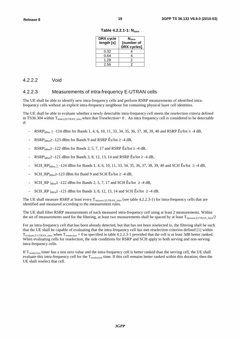
3GPP
19Release 8 3GPP TS 36.133 V8.9.0 (2010-03)
Table 4.2.2.1-1: Nserv
DRX cycle length [s]
Nserv [number of
DRX cycles] 0.32 4 0.64 4 1.28 2 2.56 2
4.2.2.2 Void
4.2.2.3 Measurements of intra-frequency E-UTRAN cells
The UE shall be able to identify new intra-frequency cells and perform RSRP measurements of identified intra-frequency cells without an explicit intra-frequency neighbour list containing physical layer cell identities.
The UE shall be able to evaluate whether a newly detectable intra-frequency cell meets the reselection criteria defined in TS36.304 within Tdetect,EUTRAN_Intra when that Treselection= 0 . An intra frequency cell is considered to be detectable if:
- RSRP|dBm > -124 dBm for Bands 1, 4, 6, 10, 11, 33, 34, 35, 36, 37, 38, 39, 40 and RSRP Ês/Iot ³ -4 dB,
- RSRP|dBm³ -123 dBm for Bands 9 and RSRP Ês/Iot ³ -4 dB,
- RSRP|dBm³ -122 dBm for Bands 2, 5, 7, 17 and RSRP Ês/Iot ³ -4 dB,
- RSRP|dBm³ -121 dBm for Bands 3, 8, 12, 13, 14 and RSRP Ês/Iot ³ -4 dB,
- SCH_RP|dBm > -124 dBm for Bands 1, 4, 6, 10, 11, 33, 34, 35, 36, 37, 38, 39, 40 and SCH Ês/Iot ³ -4 dB,
- SCH_RP|dBm³-123 dBm for Band 9 and SCH Ês/Iot ³ -4 dB,
- SCH_RP |dBm³ -122 dBm for Bands 2, 5, 7, 17 and SCH Ês/Iot ³ -4 dB,
- SCH_RP |dBm³ -121 dBm for Bands 3, 8, 12, 13, 14 and SCH Ês/Iot ³ -4 dB.
The UE shall measure RSRP at least every Tmeasure,EUTRAN_Intra (see table 4.2.2.3-1) for intra-frequency cells that are identified and measured according to the measurement rules.
The UE shall filter RSRP measurements of each measured intra-frequency cell using at least 2 measurements. Within the set of measurements used for the filtering, at least two measurements shall be spaced by at least Tmeasure,EUTRAN_Intra/2
For an intra-frequency cell that has been already detected, but that has not been reselected to, the filtering shall be such that the UE shall be capable of evaluating that the intra-frequency cell has met reselection criterion defined [1] within Tevaluate,E-UTRAN_intra when Treselection = 0 as specified in table 4.2.2.3-1 provided that the cell is at least 3dB better ranked. When evaluating cells for reselection, the side conditions for RSRP and SCH apply to both serving and non-serving intra-frequency cells.
If Treselection timer has a non zero value and the intra-frequency cell is better ranked than the serving cell, the UE shall evaluate this intra-frequency cell for the Treselection time. If this cell remains better ranked within this duration, then the UE shall reselect that cell.
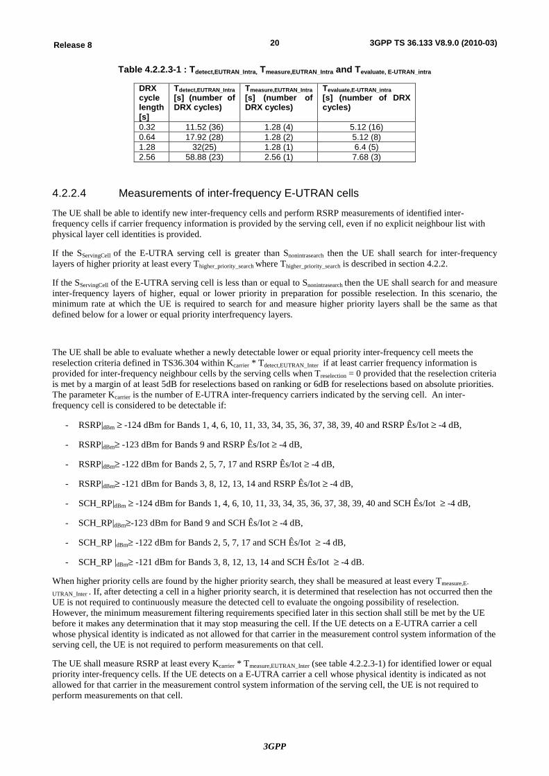
3GPP
20Release 8 3GPP TS 36.133 V8.9.0 (2010-03)
Table 4.2.2.3-1 : Tdetect,EUTRAN_Intra, Tmeasure,EUTRAN_Intra and Tevaluate, E-UTRAN_intra
DRX cycle length [s]
Tdetect,EUTRAN_Intra [s] (number of DRX cycles)
Tmeasure,EUTRAN_Intra [s] (number of DRX cycles)
Tevaluate,E-UTRAN_intra [s] (number of DRX cycles)
0.32 11.52 (36) 1.28 (4) 5.12 (16) 0.64 17.92 (28) 1.28 (2) 5.12 (8) 1.28 32(25) 1.28 (1) 6.4 (5) 2.56 58.88 (23) 2.56 (1) 7.68 (3)
4.2.2.4 Measurements of inter-frequency E-UTRAN cells
The UE shall be able to identify new inter-frequency cells and perform RSRP measurements of identified inter-frequency cells if carrier frequency information is provided by the serving cell, even if no explicit neighbour list with physical layer cell identities is provided.
If the SServingCell of the E-UTRA serving cell is greater than Snonintrasearch then the UE shall search for inter-frequency layers of higher priority at least every Thigher_priority_search where Thigher_priority_search is described in section 4.2.2.
If the SServingCell of the E-UTRA serving cell is less than or equal to Snonintrasearch then the UE shall search for and measure inter-frequency layers of higher, equal or lower priority in preparation for possible reselection. In this scenario, the minimum rate at which the UE is required to search for and measure higher priority layers shall be the same as that defined below for a lower or equal priority interfrequency layers.
The UE shall be able to evaluate whether a newly detectable lower or equal priority inter-frequency cell meets the reselection criteria defined in TS36.304 within Kcarrier * Tdetect,EUTRAN_Inter if at least carrier frequency information is provided for inter-frequency neighbour cells by the serving cells when Treselection = 0 provided that the reselection criteria is met by a margin of at least 5dB for reselections based on ranking or 6dB for reselections based on absolute priorities. The parameter Kcarrier is the number of E-UTRA inter-frequency carriers indicated by the serving cell. An inter-frequency cell is considered to be detectable if:
- RSRP|dBm ³ -124 dBm for Bands 1, 4, 6, 10, 11, 33, 34, 35, 36, 37, 38, 39, 40 and RSRP Ês/Iot ³ -4 dB,
- RSRP|dBm³ -123 dBm for Bands 9 and RSRP Ês/Iot ³ -4 dB,
- RSRP|dBm³ -122 dBm for Bands 2, 5, 7, 17 and RSRP Ês/Iot ³ -4 dB,
- RSRP|dBm³ -121 dBm for Bands 3, 8, 12, 13, 14 and RSRP Ês/Iot ³ -4 dB,
- SCH_RP|dBm ³ -124 dBm for Bands 1, 4, 6, 10, 11, 33, 34, 35, 36, 37, 38, 39, 40 and SCH Ês/Iot ³ -4 dB,
- SCH_RP|dBm³-123 dBm for Band 9 and SCH Ês/Iot ³ -4 dB,
- SCH_RP |dBm³ -122 dBm for Bands 2, 5, 7, 17 and SCH Ês/Iot ³ -4 dB,
- SCH_RP |dBm³ -121 dBm for Bands 3, 8, 12, 13, 14 and SCH Ês/Iot ³ -4 dB.
When higher priority cells are found by the higher priority search, they shall be measured at least every Tmeasure,E-
UTRAN_Inter . If, after detecting a cell in a higher priority search, it is determined that reselection has not occurred then the UE is not required to continuously measure the detected cell to evaluate the ongoing possibility of reselection. However, the minimum measurement filtering requirements specified later in this section shall still be met by the UE before it makes any determination that it may stop measuring the cell. If the UE detects on a E-UTRA carrier a cell whose physical identity is indicated as not allowed for that carrier in the measurement control system information of the serving cell, the UE is not required to perform measurements on that cell.
The UE shall measure RSRP at least every Kcarrier * Tmeasure,EUTRAN_Inter (see table 4.2.2.3-1) for identified lower or equal priority inter-frequency cells. If the UE detects on a E-UTRA carrier a cell whose physical identity is indicated as not allowed for that carrier in the measurement control system information of the serving cell, the UE is not required to perform measurements on that cell.
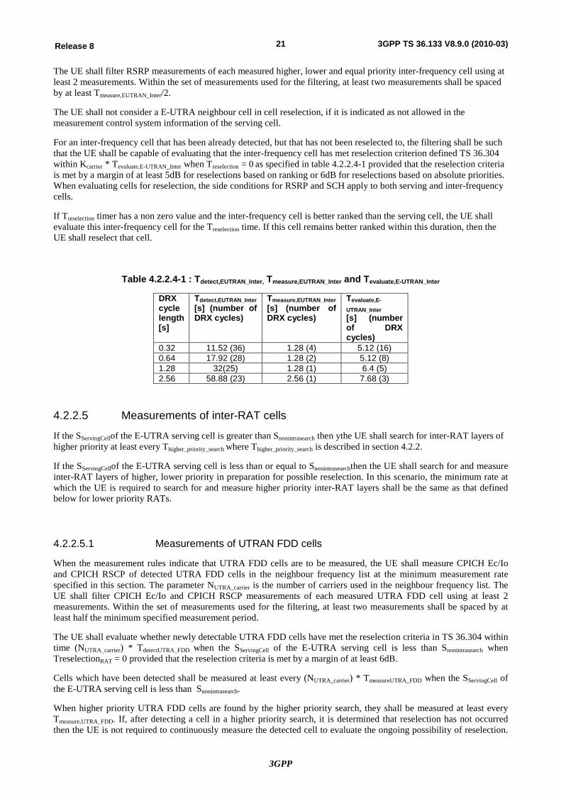
3GPP
21Release 8 3GPP TS 36.133 V8.9.0 (2010-03)
The UE shall filter RSRP measurements of each measured higher, lower and equal priority inter-frequency cell using at least 2 measurements. Within the set of measurements used for the filtering, at least two measurements shall be spaced by at least Tmeasure,EUTRAN_Inter/2.
The UE shall not consider a E-UTRA neighbour cell in cell reselection, if it is indicated as not allowed in the measurement control system information of the serving cell.
For an inter-frequency cell that has been already detected, but that has not been reselected to, the filtering shall be such that the UE shall be capable of evaluating that the inter-frequency cell has met reselection criterion defined TS 36.304 within Kcarrier * Tevaluate,E-UTRAN_Inter when Treselection = 0 as specified in table 4.2.2.4-1 provided that the reselection criteria is met by a margin of at least 5dB for reselections based on ranking or 6dB for reselections based on absolute priorities. When evaluating cells for reselection, the side conditions for RSRP and SCH apply to both serving and inter-frequency cells.
If Treselection timer has a non zero value and the inter-frequency cell is better ranked than the serving cell, the UE shall evaluate this inter-frequency cell for the Treselection time. If this cell remains better ranked within this duration, then the UE shall reselect that cell.
Table 4.2.2.4-1 : Tdetect,EUTRAN_Inter, Tmeasure,EUTRAN_Inter and Tevaluate,E-UTRAN_Inter
DRX cycle length [s]
Tdetect,EUTRAN_Inter [s] (number of DRX cycles)
Tmeasure,EUTRAN_Inter [s] (number of DRX cycles)
Tevaluate,E-UTRAN_Inter [s] (number of DRX cycles)
0.32 11.52 (36) 1.28 (4) 5.12 (16) 0.64 17.92 (28) 1.28 (2) 5.12 (8) 1.28 32(25) 1.28 (1) 6.4 (5) 2.56 58.88 (23) 2.56 (1) 7.68 (3)
4.2.2.5 Measurements of inter-RAT cells
If the SServingCellof the E-UTRA serving cell is greater than Snonintrasearch then ythe UE shall search for inter-RAT layers of higher priority at least every Thigher_priority_search where Thigher_priority_search is described in section 4.2.2.
If the SServingCellof the E-UTRA serving cell is less than or equal to Snonintrasearchthen the UE shall search for and measure inter-RAT layers of higher, lower priority in preparation for possible reselection. In this scenario, the minimum rate at which the UE is required to search for and measure higher priority inter-RAT layers shall be the same as that defined below for lower priority RATs.
4.2.2.5.1 Measurements of UTRAN FDD cells
When the measurement rules indicate that UTRA FDD cells are to be measured, the UE shall measure CPICH Ec/Io and CPICH RSCP of detected UTRA FDD cells in the neighbour frequency list at the minimum measurement rate specified in this section. The parameter NUTRA_carrier is the number of carriers used in the neighbour frequency list. The UE shall filter CPICH Ec/Io and CPICH RSCP measurements of each measured UTRA FDD cell using at least 2 measurements. Within the set of measurements used for the filtering, at least two measurements shall be spaced by at least half the minimum specified measurement period.
The UE shall evaluate whether newly detectable UTRA FDD cells have met the reselection criteria in TS 36.304 within time (NUTRA_carrier) * TdetectUTRA_FDD when the SServingCell of the E-UTRA serving cell is less than Snonintrasearch when TreselectionRAT = 0 provided that the reselection criteria is met by a margin of at least 6dB.
Cells which have been detected shall be measured at least every (NUTRA_carrier) * TmeasureUTRA_FDD when the SServingCell of the E-UTRA serving cell is less than Snonintrasearch.
When higher priority UTRA FDD cells are found by the higher priority search, they shall be measured at least every Tmeasure,UTRA_FDD. If, after detecting a cell in a higher priority search, it is determined that reselection has not occurred then the UE is not required to continuously measure the detected cell to evaluate the ongoing possibility of reselection.
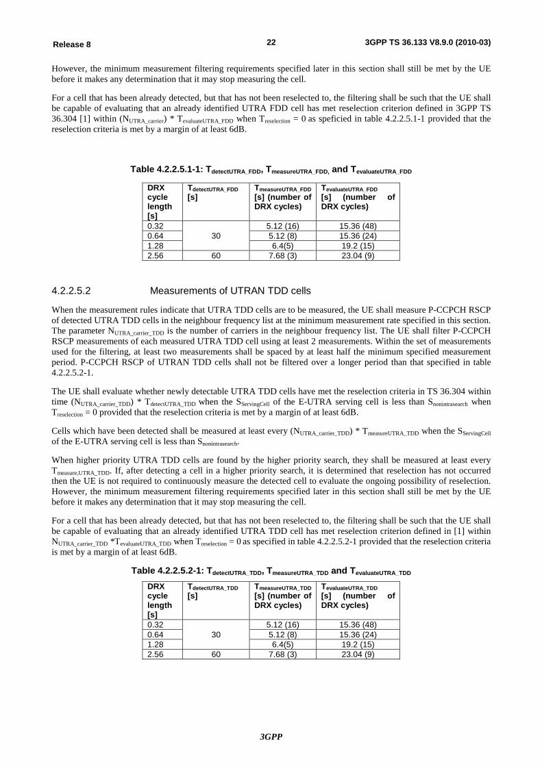
3GPP
22Release 8 3GPP TS 36.133 V8.9.0 (2010-03)
However, the minimum measurement filtering requirements specified later in this section shall still be met by the UE before it makes any determination that it may stop measuring the cell.
For a cell that has been already detected, but that has not been reselected to, the filtering shall be such that the UE shall be capable of evaluating that an already identified UTRA FDD cell has met reselection criterion defined in 3GPP TS 36.304 [1] within (NUTRA_carrier) * TevaluateUTRA_FDD when Treselection = 0 as speficied in table 4.2.2.5.1-1 provided that the reselection criteria is met by a margin of at least 6dB.
Table 4.2.2.5.1-1: TdetectUTRA_FDD, TmeasureUTRA_FDD, and TevaluateUTRA_FDD
DRX cycle length [s]
TdetectUTRA_FDD [s]
TmeasureUTRA_FDD [s] (number of DRX cycles)
TevaluateUTRA_FDD [s] (number of DRX cycles)
0.32 30
5.12 (16) 15.36 (48) 0.64 5.12 (8) 15.36 (24) 1.28 6.4(5) 19.2 (15) 2.56 60 7.68 (3) 23.04 (9)
4.2.2.5.2 Measurements of UTRAN TDD cells
When the measurement rules indicate that UTRA TDD cells are to be measured, the UE shall measure P-CCPCH RSCP of detected UTRA TDD cells in the neighbour frequency list at the minimum measurement rate specified in this section. The parameter NUTRA_carrier_TDD is the number of carriers in the neighbour frequency list. The UE shall filter P-CCPCH RSCP measurements of each measured UTRA TDD cell using at least 2 measurements. Within the set of measurements used for the filtering, at least two measurements shall be spaced by at least half the minimum specified measurement period. P-CCPCH RSCP of UTRAN TDD cells shall not be filtered over a longer period than that specified in table 4.2.2.5.2-1.
The UE shall evaluate whether newly detectable UTRA TDD cells have met the reselection criteria in TS 36.304 within time (NUTRA_carrier_TDD) * TdetectUTRA_TDD when the SServingCell of the E-UTRA serving cell is less than Snonintrasearch when Treselection = 0 provided that the reselection criteria is met by a margin of at least 6dB.
Cells which have been detected shall be measured at least every (NUTRA_carrier_TDD) * TmeasureUTRA_TDD when the SServingCell of the E-UTRA serving cell is less than Snonintrasearch.
When higher priority UTRA TDD cells are found by the higher priority search, they shall be measured at least every Tmeasure,UTRA_TDD. If, after detecting a cell in a higher priority search, it is determined that reselection has not occurred then the UE is not required to continuously measure the detected cell to evaluate the ongoing possibility of reselection. However, the minimum measurement filtering requirements specified later in this section shall still be met by the UE before it makes any determination that it may stop measuring the cell.
For a cell that has been already detected, but that has not been reselected to, the filtering shall be such that the UE shall be capable of evaluating that an already identified UTRA TDD cell has met reselection criterion defined in [1] within NUTRA_carrier_TDD *TevaluateUTRA_TDD when Treselection = 0 as specified in table 4.2.2.5.2-1 provided that the reselection criteria is met by a margin of at least 6dB.
Table 4.2.2.5.2-1: TdetectUTRA_TDD, TmeasureUTRA_TDD and TevaluateUTRA_TDD
DRX cycle length [s]
TdetectUTRA_TDD [s]
TmeasureUTRA_TDD [s] (number of DRX cycles)
TevaluateUTRA_TDD [s] (number of DRX cycles)
0.32 30
5.12 (16) 15.36 (48) 0.64 5.12 (8) 15.36 (24) 1.28 6.4(5) 19.2 (15) 2.56 60 7.68 (3) 23.04 (9)
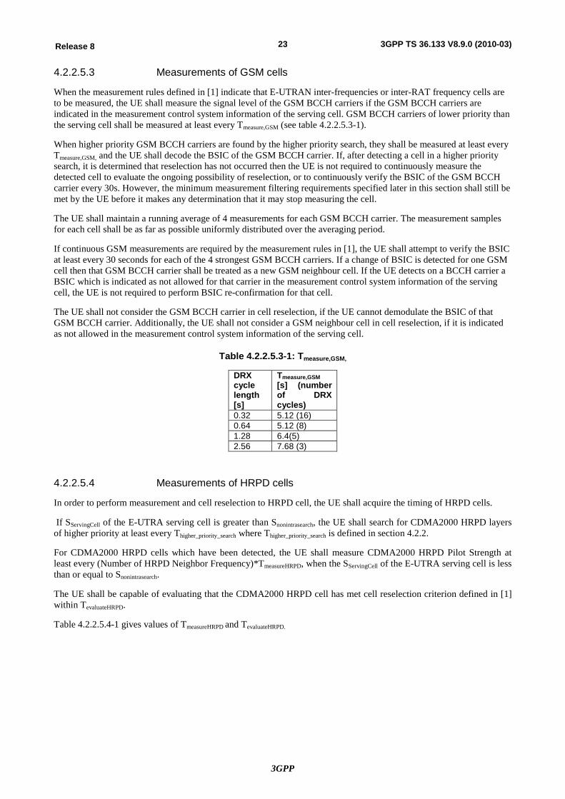
3GPP
23Release 8 3GPP TS 36.133 V8.9.0 (2010-03)
4.2.2.5.3 Measurements of GSM cells
When the measurement rules defined in [1] indicate that E-UTRAN inter-frequencies or inter-RAT frequency cells are to be measured, the UE shall measure the signal level of the GSM BCCH carriers if the GSM BCCH carriers are indicated in the measurement control system information of the serving cell. GSM BCCH carriers of lower priority than the serving cell shall be measured at least every Tmeasure,GSM (see table 4.2.2.5.3-1).
When higher priority GSM BCCH carriers are found by the higher priority search, they shall be measured at least every Tmeasure,GSM, and the UE shall decode the BSIC of the GSM BCCH carrier. If, after detecting a cell in a higher priority search, it is determined that reselection has not occurred then the UE is not required to continuously measure the detected cell to evaluate the ongoing possibility of reselection, or to continuously verify the BSIC of the GSM BCCH carrier every 30s. However, the minimum measurement filtering requirements specified later in this section shall still be met by the UE before it makes any determination that it may stop measuring the cell.
The UE shall maintain a running average of 4 measurements for each GSM BCCH carrier. The measurement samples for each cell shall be as far as possible uniformly distributed over the averaging period.
If continuous GSM measurements are required by the measurement rules in [1], the UE shall attempt to verify the BSIC at least every 30 seconds for each of the 4 strongest GSM BCCH carriers. If a change of BSIC is detected for one GSM cell then that GSM BCCH carrier shall be treated as a new GSM neighbour cell. If the UE detects on a BCCH carrier a BSIC which is indicated as not allowed for that carrier in the measurement control system information of the serving cell, the UE is not required to perform BSIC re-confirmation for that cell.
The UE shall not consider the GSM BCCH carrier in cell reselection, if the UE cannot demodulate the BSIC of that GSM BCCH carrier. Additionally, the UE shall not consider a GSM neighbour cell in cell reselection, if it is indicated as not allowed in the measurement control system information of the serving cell.
Table 4.2.2.5.3-1: Tmeasure,GSM,
DRX cycle length [s]
Tmeasure,GSM [s] (number of DRX cycles)
0.32 5.12 (16) 0.64 5.12 (8) 1.28 6.4(5) 2.56 7.68 (3)
4.2.2.5.4 Measurements of HRPD cells
In order to perform measurement and cell reselection to HRPD cell, the UE shall acquire the timing of HRPD cells.
If SServingCell of the E-UTRA serving cell is greater than Snonintrasearch, the UE shall search for CDMA2000 HRPD layers of higher priority at least every Thigher_priority_search where Thigher_priority_search is defined in section 4.2.2.
For CDMA2000 HRPD cells which have been detected, the UE shall measure CDMA2000 HRPD Pilot Strength at least every (Number of HRPD Neighbor Frequency)*TmeasureHRPD, when the SServingCell of the E-UTRA serving cell is less than or equal to Snonintrasearch.
The UE shall be capable of evaluating that the CDMA2000 HRPD cell has met cell reselection criterion defined in [1] within TevaluateHRPD.
Table 4.2.2.5.4-1 gives values of TmeasureHRPD and TevaluateHRPD.
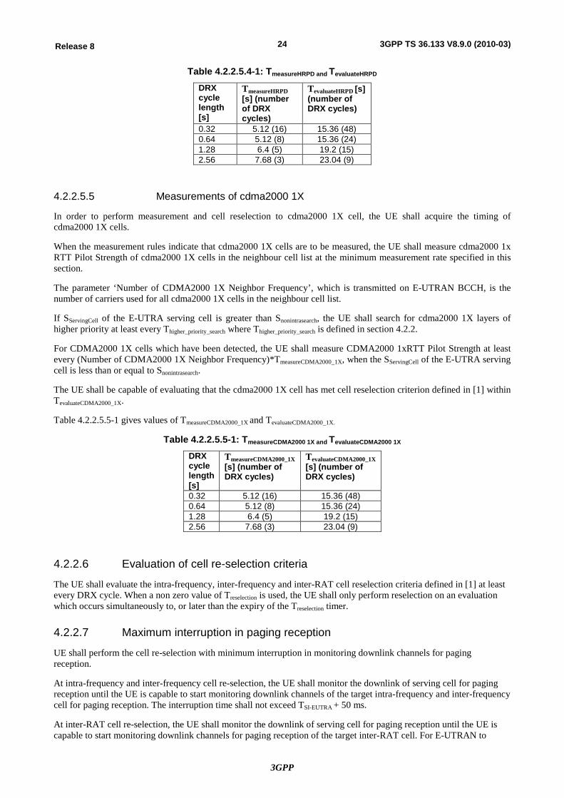
3GPP
24Release 8 3GPP TS 36.133 V8.9.0 (2010-03)
Table 4.2.2.5.4-1: TmeasureHRPD and TevaluateHRPD
DRX cycle length [s]
TmeasureHRPD [s] (number of DRX cycles)
TevaluateHRPD [s] (number of DRX cycles)
0.32 5.12 (16) 15.36 (48) 0.64 5.12 (8) 15.36 (24) 1.28 6.4 (5) 19.2 (15) 2.56 7.68 (3) 23.04 (9)
4.2.2.5.5 Measurements of cdma2000 1X
In order to perform measurement and cell reselection to cdma2000 1X cell, the UE shall acquire the timing of cdma2000 1X cells.
When the measurement rules indicate that cdma2000 1X cells are to be measured, the UE shall measure cdma2000 1x RTT Pilot Strength of cdma2000 1X cells in the neighbour cell list at the minimum measurement rate specified in this section.
The parameter ‘Number of CDMA2000 1X Neighbor Frequency’, which is transmitted on E-UTRAN BCCH, is the number of carriers used for all cdma2000 1X cells in the neighbour cell list.
If SServingCell of the E-UTRA serving cell is greater than Snonintrasearch, the UE shall search for cdma2000 1X layers of higher priority at least every Thigher_priority_search where Thigher_priority_search is defined in section 4.2.2.
For CDMA2000 1X cells which have been detected, the UE shall measure CDMA2000 1xRTT Pilot Strength at least every (Number of CDMA2000 1X Neighbor Frequency)*TmeasureCDMA2000_1X, when the SServingCell of the E-UTRA serving cell is less than or equal to Snonintrasearch.
The UE shall be capable of evaluating that the cdma2000 1X cell has met cell reselection criterion defined in [1] within TevaluateCDMA2000_1X.
Table 4.2.2.5.5-1 gives values of TmeasureCDMA2000_1X and TevaluateCDMA2000_1X.
Table 4.2.2.5.5-1: TmeasureCDMA2000 1X and TevaluateCDMA2000 1X
DRX cycle length [s]
TmeasureCDMA2000_1X [s] (number of DRX cycles)
TevaluateCDMA2000_1X [s] (number of DRX cycles)
0.32 5.12 (16) 15.36 (48) 0.64 5.12 (8) 15.36 (24) 1.28 6.4 (5) 19.2 (15) 2.56 7.68 (3) 23.04 (9)
4.2.2.6 Evaluation of cell re-selection criteria
The UE shall evaluate the intra-frequency, inter-frequency and inter-RAT cell reselection criteria defined in [1] at least every DRX cycle. When a non zero value of Treselection is used, the UE shall only perform reselection on an evaluation which occurs simultaneously to, or later than the expiry of the Treselection timer.
4.2.2.7 Maximum interruption in paging reception
UE shall perform the cell re-selection with minimum interruption in monitoring downlink channels for paging reception.
At intra-frequency and inter-frequency cell re-selection, the UE shall monitor the downlink of serving cell for paging reception until the UE is capable to start monitoring downlink channels of the target intra-frequency and inter-frequency cell for paging reception. The interruption time shall not exceed TSI-EUTRA + 50 ms.
At inter-RAT cell re-selection, the UE shall monitor the downlink of serving cell for paging reception until the UE is capable to start monitoring downlink channels for paging reception of the target inter-RAT cell. For E-UTRAN to
3GPP
25Release 8 3GPP TS 36.133 V8.9.0 (2010-03)
UTRA cell re-selection the interruption time must not exceed TSI-UTRA + 50 ms. For E-UTRAN to GSM cell re-selection the interruption time must not exceed TBCCH + 50 ms.
TSI-EUTRA is the time required for receiving all the relevant system information data according to the reception procedure and the RRC procedure delay of system information blocks defined in [2] for a E-UTRAN cell.
TSI-UTRA is the time required for receiving all the relevant system information data according to the reception procedure and the RRC procedure delay of system information blocks defined in [7] for a UTRAN cell.
TBCCH is the maximum time allowed to read BCCH data from a GSM cell defined in [8].
These requirements assume sufficient radio conditions, so that decoding of system information can be made without errors and does not take into account cell re-selection failure.
At cell re-selection to HRPD, the UE shall monitor the downlink of serving cell for paging reception until the UE is capable of starting to monitor downlink channels for paging reception of the target HRPD cell. For HRPD cell re-selection the interruption time must not exceed TSI-HRPD + 50 ms.
TSI-HRPD is the time required for receiving all the relevant system information data according to the reception procedure and the upper layer (Layer 3) procedure delay of system information blocks defined in [11] in for HRPD cell.
At cell re-selection to cdma2000 1X, the UE shall monitor the downlink of serving cell for paging reception until the UE is capable of starting to monitor downlink channels for paging reception of the target cdma2000 1X cell. For cdma2000 1X cell re-selection the interruption time must not exceed TSI-cdma2000_1X + 50 ms.
TSI-cdma2000_1X is the time required for receiving all the relevant system information data according to the reception procedure and the upper layer (Layer 3) procedure delay of system information blocks defined in [15] for cdma2000 1X cell.
4.2.2.8 void
4.2.2.9 UE measurement capability
For idle mode cell re-selection purposes, the UE shall be capable of monitoring at least:
- Intra-frequency carrier, and
- Depending on UE capability, 3 FDD E-UTRA inter-frequency carriers, and
- Depending on UE capability, 3 TDD E-UTRA inter-frequency carriers, and
- Depending on UE capability, 3 FDD UTRA carriers, and
- Depending on UE capability, 3 TDD UTRA carriers, and
- Depending on UE capability, 32 GSM carriers, and
- Depending on UE capability, 3 cdma2000 1x carriers, and
- Depending on UE capability, 3 HRPD carriers.
In addition to the requirements defined above, a UE in RRC_IDLE state shall be capable of monitoring a total of at least 8 carrier frequency layers, which includes serving layer, comprising of any above defined combination of E-UTRA FDD, E-UTRA TDD, UTRA FDD, UTRA TDD, GSM (one GSM layer corresponds to 32 cells) , cdma2000 1x and HRPD layers.
5 E-UTRAN RRC_CONNECTED state mobility Note: For the performance requirements specified hereafter, the state when no DRX is used is defined as follows:
3GPP
26Release 8 3GPP TS 36.133 V8.9.0 (2010-03)
- DRX parameters are not configured; or
- DRX parameters are configured and
o drx-InactivityTimer is running; or
o drx-RetransmissionTimer is running; or
o mac-ContentionResolutionTimer is running; or
o a Scheduling Request sent on PUCCH is pending; or
o an uplink grant for a pending HARQ retransmission can occur and there is data in the corresponding HARQ buffer; or
o a PDCCH indicating a new transmission addressed to the C-RNTI of the UE has not been received after successful reception of a Random Access Response for the explicitly signaled preamble (only applicable to UEs in RRC_CONNECTED).
Otherwise
- It is the state when DRX is used.
5.1 E-UTRAN Handover
5.1.1 Introduction
5.1.2 Requirements
5.1.2.1 E-UTRAN FDD – FDD
The requirements in this section are applicable to both intra-frequency and inter-frequency handovers.
5.1.2.1.1 Handover delay
Procedure delays for all procedures that can command a handover are specified in [2].
When the UE receives a RRC message implying handover the UE shall be ready to start the transmission of the new uplink PRACH channel within Dhandover seconds from the end of the last TTI containing the RRC command.
Where:
Dhandover equals the maximum RRC procedure delay to be defined in section 11.2 in 3GPP TS 36.331 [2] plus the interruption time stated in section 5.1.2.1.2.
5.1.2.1.2 Interruption time
The interruption time is the time between end of the last TTI containing the RRC command on the old PDSCH and the time the UE starts transmission of the new PRACH, excluding the RRC procedure delay. This requirement applies when UE is not required to perform any synchronisation procedure before transmitting on the new PRACH.
When intra-frequency or inter-frequency handover is commanded, the interruption time shall be less than Tinterrupt
Tinterrupt = Tsearch + TIU + 20 ms
Where:
Tsearch is the time required to search the target cell when the target cell is not already known when the handover command is received by the UE. If the target cell is known, then Tsearch = 0 ms. If the target cell is unknown and
3GPP
27Release 8 3GPP TS 36.133 V8.9.0 (2010-03)
signal quality is sufficient for successful cell detection on the first attempt, then Tsearch = 80 ms. Regardless of whether DRX is in use by the UE, Tsearch shall still be based on non-DRX target cell search times
TIU is the interruption uncertainty in acquiring the first available PRACH occasion in the new cell. TIU can be up to 30 ms.
NOTE: The actual value of TIU shall depend upon the PRACH configuration used in the target cell.
In the interruption requirement a cell is known if it has been meeting the relevant cell identification requirement during the last 5 seconds otherwise it is unknown. Relevant cell identification requirements are described in Section 8.1.2.2.1 for intra-frequency handover and Section 8.1.2.3.1 for inter-frequency handover.
5.2.2.2 E-UTRAN FDD – TDD
The requirements in this section are applicable to handover from FDD to TDD. The requirements in this section shall apply to UE supporting FDD and TDD.
The requirements in section 5.2.2.4 apply for this section.
5.2.2.2.1 (Void)
5.2.2.2.2 (Void)
5.2.2.3 E-UTRAN TDD – FDD
The requirements in this section are applicable to handover from TDD to FDD. The requirements in this section shall apply to UE supporting FDD and TDD.
The requirements in section 5.1.2.1 apply for this section.
5.2.2.3.1 (Void)
5.2.2.3.2 (Void)
5.2.2.4 E-UTRAN TDD – TDD
The requirements in this section are applicable to both intra-frequency and inter-frequency handovers.
5.2.2.4.1 Handover delay
Procedure delays for all procedures that can command a handover are specified in 3GPP TS 36.331 [2].
When the UE receives a RRC message implying handover, the UE shall be ready to start the transmission of the new uplink PRACH channel within Dhandover seconds from the end of the last TTI containing the RRC command.
Where:
Dhandover equals the maximum RRC procedure delay to be defined in section 11.2 in 3GPP TS36.331 [2] plus the interruption time stated in section 5. 2.2.4.2.
5.2.2.4.2 Interruption time
The interruption time is the time between end of the last TTI containing the RRC command on the old PDSCH and the time the UE starts transmission of the new PRACH, excluding the RRC procedure delay. This requirement applies when UE is not required to perform any synchronisation procedure before transmitting on the new PRACH.
When intra-frequency or inter-frequency handover is commanded, the interruption time shall be less than Tinterrupt
Tinterrupt = Tsearch + TIU + 20 ms
3GPP
28Release 8 3GPP TS 36.133 V8.9.0 (2010-03)
Where
Tsearch is the time required to search the target cell when the target cell is not already known when the handover command is received by the UE. If the target cell is known, then Tsearch = 0 ms. If the target cell is unknown and signal quality is sufficient for successful cell detection on the first attempt, then Tsearch = 80 ms. Regardless of whether DRX is in use by the UE, Tsearch shall still be based on non-DRX target cell search times.
TIU is the interruption uncertainty in acquiring the first available PRACH occasion in the new cell. TIU can be up to 30 ms.
NOTE: The actual value of TIU shall depend upon the PRACH configuration used in the target cell.
In the interruption requirement a cell is known if it has been meeting the relevant cell identification requirement during the last 5 seconds otherwise it is unknown. Relevant cell identification requirements are described in Section 8.1.2.2.2 for intra-frequency handover and Section 8.1.2.3.4 for inter-frequency handover.
5.3 Handover to other RATs
5.3.1 E-UTRAN - UTRAN FDD Handover
5.3.1.1 Introduction
The purpose of inter-RAT handover from E-UTRAN to UTRAN FDD is to change the radio access mode from E-UTRAN to UTRAN FDD. The handover procedure is initiated from E-UTRAN with a RRC message that implies a hard handover as described in [2].
5.3.1.1.1 Handover delay
When the UE receives a RRC message implying handover to UTRAN the UE shall be ready to start the transmission of the new UTRA uplink DPCCH within Dhandover seconds from the end of the last E-UTRAN TTI containing the RRC MOBILITY FROM E-UTRA command.
where:
- Dhandover equals the RRC procedure delay, which is 50 ms plus the interruption time stated in section 5.3.1.1.2.
5.3.1.1.2 Interruption time
The interruption time is the time between the end of the last TTI containing the RRC command on the E-UTRAN PDSCH and the time the UE starts transmission on the uplink DPCCH in UTRAN FDD, excluding the RRC procedure delay. The interruption time depends on whether the target cell is known to the UE or not.
The target cell is known if it has been measured by the UE during the last 5 seconds otherwise it is unknown. The UE shall always perform a UTRA synchronisation procedure as part of the handover procedure.
If the target cell is known the interruption time shall be less than Tinterrupt1
Tinterrupt1 = TIU+Tsync+50+ 10*Fmax ms
If the target cell is unknown the interruption time shall be less than Tinterrupt2
Tinterrupt2 = TIU+Tsync+150 + 10*Fmax ms
This requirement shall be met, provided that there is one target cell in the MOBILITY FROM E-UTRA command. Performance requirements for E-UTRA to UTRA soft handover are not specified. When UE is connected to an E-UTRA cell, UTRA SFN timing measurements are not reported. This implies that the timing of the DPCH of the UTRA
3GPP
29Release 8 3GPP TS 36.133 V8.9.0 (2010-03)
target cells in the active set cannot be configured by UTRAN to guarantee that all target cells fall within the UE reception window of T0 +/- 148 chips.
Where:
TIU is the interruption uncertainty when changing the timing from the E-UTRAN to the new UTRAN cell. TIU can be up to one UTRA frame (10 ms).
Fmax denotes the maximum number of radio frames within the transmission time intervals of all transport channels that are multiplexed into the same CCTrCH on the UTRA target cell.
Tsync is the time required for measuring the downlink DPCCH channel as stated in 3GPP TS 25.214 section 4.3.1.2 [20]. In case higher layers indicate the usage of a post-verification period Tsync=0 ms. Otherwise Tsync=40 ms.
The phase reference is the primary CPICH.
The requirements in this section assume that N312 has the smallest possible value i.e. only one insync is required.
5.3.2 E-UTRAN - UTRAN TDD Handover
5.3.2.1 Introduction
The purpose of inter-RAT handover from E-UTRAN to UTRAN TDD is to change the radio access mode from E-UTRAN to UTRAN TDD. The handover procedure is initiated from E-UTRAN with a RRC message that implies a hard handover as described in [2].
5.3.2.2 Requirements
The requirements in this section shall apply to UE supporting E-UTRAN and UTRAN TDD.
5.3.2.2.1 Handover delay
When the UE receives a RRC message implying E-UTRAN/UTRAN TDD handover the UE shall be ready to start the transmission of the new uplink DPCH or the SYNC-UL within Dhandover seconds from the end of the last TTI containing the RRC MOBILITY FROM E-UTRA command.
Where:
- Dhandover equals the RRC procedure delay, which is 50 ms plus the interruption time stated in section 5.3.2.2.
5.3.2.2.2 Interruption time
The interruption time is the time between the end of the last TTI containing the RRC command on the E-UTRAN PDSCH and the time the UE starts transmission on the uplink DPCH or the SYNC-UL in UTRAN TDD, excluding the RRC procedure delay. The interruption time depends on whether the target cell is known to the UE or not.
The UE shall always perform a UTRA synchronisation procedure as part of the handover procedure.
If the target cell has been measured by the UE during the last 5 seconds, the interruption time shall be less than Tinterrupt1
Tinterrupt1= Toffset+TUL+30*FSFN+[20] +10*Fmax ms
If the target cell has not been measured by the UE during the last 5 seconds, the interruption time shall be less than Tinterrupt2
Tinterrupt2= Toffset+TUL+30*FSFN+[180] +10*Fmax ms
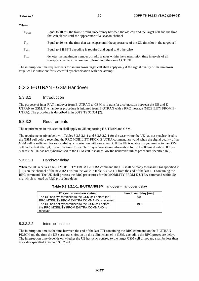
3GPP
30Release 8 3GPP TS 36.133 V8.9.0 (2010-03)
Where:
Toffset Equal to 10 ms, the frame timing uncertainty between the old cell and the target cell and the time that can elapse until the appearance of a Beacon channel
TUL Equal to 10 ms, the time that can elapse until the appearance of the UL timeslot in the target cell
FSFN Equal to 1 if SFN decoding is required and equal to 0 otherwise
Fmax denotes the maximum number of radio frames within the transmission time intervals of all transport channels that are multiplexed into the same CCTrCH.
The interruption time requirements for an unknown target cell shall apply only if the signal quality of the unknown target cell is sufficient for successful synchronisation with one attempt.
5.3.3 E-UTRAN - GSM Handover
5.3.3.1 Introduction
The purpose of inter-RAT handover from E-UTRAN to GSM is to transfer a connection between the UE and E-UTRAN to GSM. The handover procedure is initiated from E-UTRAN with a RRC message (MOBILITY FROM E-UTRA). The procedure is described in in 3GPP TS 36.331 [2].
5.3.3.2 Requirements
The requirements in this section shall apply to UE supporting E-UTRAN and GSM.
The requirements given below in Tables 5.3.3.2.1-1 and 5.3.3.2.2-1 for the case where the UE has not synchronised to the GSM cell before receiving the RRC MOBILITY FROM E-UTRA command are valid when the signal quality of the GSM cell is sufficient for successful synchronisation with one attempt. If the UE is unable to synchronise to the GSM cell on the first attempt, it shall continue to search for synchronisation information for up to 800 ms duration. If after 800 ms the UE has not synchronised to the GSM cell it shall follow the handover failure procedure specified in [2].
5.3.3.2.1 Handover delay
When the UE receives a RRC MOBILITY FROM E-UTRA command the UE shall be ready to transmit (as specified in [10]) on the channel of the new RAT within the value in table 5.3.3.2.1-1 from the end of the last TTI containing the RRC command. The UE shall process the RRC procedures for the MOBILITY FROM E-UTRA command within 50 ms, which is noted as RRC procedure delay.
Table 5.3.3.2.1-1: E-UTRAN/GSM handover - handover delay
UE synchronisation status handover delay [ms] The UE has synchronised to the GSM cell before the RRC MOBILITY FROM E-UTRA COMMAND is received
90
The UE has not synchronised to the GSM cell before the RRC MOBILITY FROM E-UTRA COMMAND is received
190
5.3.3.2.2 Interruption time
The interruption time is the time between the end of the last TTI containing the RRC command on the E-UTRAN PDSCH and the time the UE starts transmission on the uplink channel in GSM, excluding the RRC procedure delay. The interruption time depends on whether the UE has synchronized to the target GSM cell or not and shall be less than the value specified in table 5.3.3.2.2-1.
3GPP
31Release 8 3GPP TS 36.133 V8.9.0 (2010-03)
Table 5.3.3.2.2-1: E-UTRAN/GSM handover - interruption time
Synchronisation status Interruption time [ms] The UE has synchronised to the GSM cell before the RRC MOBILITY FROM E-UTRA COMMAND is received
40
The UE has not synchronised to the GSM cell before the RRC MOBILITY FROM E-UTRA COMMAND is received
140
5.4 Handover to Non-3GPP RATs
5.4.1 E-UTRAN – HRPD Handover
5.4.1.1 Introduction
The handover procedure from E-UTRAN to HRPD is initiated when E-UTRAN sends handover command to the UE through dedicated RRC signalling.
5.4.1.1.1 Handover delay
The handover delay (Dhandover) is defined as the sum of the RRC procedure delay, which is 50 ms and the interruption time specified in section 5.4.1.1.2.
When the UE receives a RRC message implying handover to HRPD, the UE shall be ready to start the transmission of the new reverse control channel in HRPD within Dhandover from the end of the last E-UTRAN TTI containing the RRC command.
5.4.1.1.2 Interruption time
The interruption time is the time between the end of the last TTI containing the RRC command on the E-UTRAN PDSCH and the time the UE starts transmission of the reverse control channel in HRPD, excluding the RRC procedure delay. The interruption time depends on whether the target cell is known to the UE or not.
An HRPD cell is known if it has been measured by the UE during the last 5 seconds otherwise it is unknown. Under the reference conditions specified in sub-clause 6.6 of [13], the interruption time shall be less than Tinterrupt
Tinterrupt = TIU + [40] + [10]*KC*SWK + [10]*OC*SWO ms
Where:
TIU It is the interruption uncertainty when changing the timing from the E-UTRAN to the new HRPD cell. TIU can be up to one HRPD frame (26.66 ms).
SWK is SWK = úúù
êêé
60srch_win_k
where srch_win_k is the number of HRPD chips indicated by the
search window for known target HRPD cells in the message
SWO is SWO = úúù
êêé
60srch_win_o
where srch_win_o is the number of HRPD chips indicated by the
search window for unknown target HRPD cells in the message
KC It is the number of known target HRPD cells in the message, and
OC It is the number of unknown target HRPD cells in the message.
Note: An additional delay in the interruption time may occur due to the reverse link silence interval [11], which is specific to HRPD.
3GPP
32Release 8 3GPP TS 36.133 V8.9.0 (2010-03)
5.4.2 E-UTRAN – cdma2000 1X Handover
5.4.2.1 Introduction
The handover procedure from E-UTRAN to cdma2000 1X is initiated when E-UTRAN sends handover command to the UE through dedicated RRC signalling.
5.4.2.1.1 Handover delay
The handover delay (Dhandover) is defined as the sum of the RRC procedure delay, which is 130 ms and the interruption time specified in section 5.4.2.1.2.
When the UE receives a RRC message implying handover to cdma2000 1X, the UE shall be ready to start the transmission of the new reverse control channel in cdma2000 1X within Dhandover from the end of the last E-UTRAN TTI containing the RRC command.
5.4.2.1.2 Interruption time
The interruption time is the time between the end of the last TTI containing the RRC command on the E-UTRAN PDSCH and the time the UE starts transmission of the reverse control channel in cdma2000 1X, excluding the RRC procedure delay. The interruption time depends on whether the target cell is known to the UE or not.
A cdma2000 1X cell is known if it has been measured by the UE during the last 5 seconds otherwise it is unknown. Under the reference conditions specified in sub-clause 4.2.1 of [14], the interruption time shall be less than Tinterrupt:
Tinterrupt = TIU + [40] + [10]*KC*SWK + [10]*OC*SWO ms
Where:
TIU It is the interruption uncertainty when changing the timing from the E-UTRAN to the new cdma2000 1X cell. TIU can be up to one cdma2000 1X frame (20 ms).
SWK is SWK = úúù
êêé
60srch_win_k
where srch_win_k is the number of cdma2000 1x chips indicated by
the search window for known target cdma2000 1x cells in the message
SWO is SWO = úúù
êêé
60srch_win_o
where srch_win_o is the number of cdma2000 1x chips indicated by
the search window for unknown target cdma2000 1x cells in the message
KC It is the number of known target cdma2000 1X cells in the message, and
OC It is the number of unknown target cdma2000 1X cells in the message.
6 RRC Connection Mobility Control
6.1 RRC Re-establishment The requirements in this section are applicable to both E-UTRAN FDD and TDD.
6.1.1 Introduction
RRC connection re-establishment is initiated when a UE in RRC connected mode looses RRC connection due to any of these reasons: radio link failure, handover failure or radio link problem. The RRC es-tablishment procedure is specified in section 5.3.7 in TS 36.331 [2].
3GPP
33Release 8 3GPP TS 36.133 V8.9.0 (2010-03)
6.1.2 Requirements
In RRC connected mode the UE shall be capable of sending RRCConnectionReestablishmentRequest message within Tre-establish_delay seconds from the moment it detects a loss in RRC connection. The total RRC connection delay (Tre-
establish_delay) shall be less than:
Tre-establish_delay = TUL_grant + TUE_re-establish_delay
TUL_grant: It is the time required to acquire and process uplink grant from the target cell. The uplink grant is required to transmit RRCConnectionReestablishmentRequest message.
The UE re-establishment delay (TUE_re-establish_delay) is specified in section 6.1.2.1.
6.1.2.1 UE Re-establishment delay requirement
The UE re-establishment delay (TUE_re-establish_delay) is the time between the moments when any of the conditions requiring RRC re-estbalishment as defined in section 5.3.7 in TS 36.331 [2] is detected by the UE to the time when the UE sends PRACH to the target cell. The UE re-establishment delay (TUE_re-establish_delay) requirement shall be less than:
TUE-re-establish_delay = 50 ms + Nfreq*Tsearch + TSI + TPRACH
Tsearch: It is the time required by the UE to search the target cell.
Tsearch = It is [100] ms if the target cell is known by the UE; the target cell is known if it has been measured by the UE in the last 5 seconds.
Tsearch = It is 800 ms if the target cell is unknown by the UE; the target cell is unknown if it has not been measured by the UE in the last 5 seconds.
TSI = It is the time required for receiving all the relevant system information according to the reception procedure and the RRC procedure delay of system information blocks defined in TS 36.331 [2] for E-UTRAN cell.
TPRACH = The additional delay caused by the random access procedure; it will be at least 10 ms due to random access occasion and there might be additional delay due to ramping procedure.
Nfreq: It is the total number of E-UTRA frequencies to be monitored for RRC re-establishment; Nfreq = 1 if the target cell is known.
There is no requirement if the target cell does not contain the UE context.
6.2 Random Access
6.2.1 Introduction The random access procedure is used when establishing the layer 1 communication between the UE and E-UTRAN. The random access is specified in section 6 of TS 36.213[3] and the control of the RACH transmission is specified in section 5.1 of TS 36.321[17].
6.2.2 Requirements The UE shall have capability to calculate PRACH transmission power according to the PRACH power formula defined in TS 36.213[3] and apply this power level at the first preamble or additional preambles. The absolute power applied to the first preamble shall have an accuracy as specified in table 6.3.5.1.1-1 of TS 36.101[5]. The relative power applied to additional preambles shall have an accuracy as specified in table 6.3.5.2.1-1 of 36.101[5].
The UE shall indicate a Random Access problem to upper layers if the maximum number of preamble transmission counter has been reached.
3GPP
34Release 8 3GPP TS 36.133 V8.9.0 (2010-03)
6.2.2.1 Contention based random access
6.2.2.1.1 Correct behaviour when receiving Random Access Response reception
The UE may stop monitoring for Random Access Response(s) and shall transmit the msg3 if the Random Access Response contains a Random Access Preamble identifier corresponding to the transmitted Random Access Preamble.
The UE shall re-select a preamble and transmit with the calculated PRACH transmission power when the backoff time expires if all received Random Access Responses contain Random Access Preamble identifiers that do not match the transmitted Random Access Preamble.
6.2.2.1.2 Correct behaviour when not receiving Random Access Response reception
The UE shall re-select a preamble and transmit with the calculated PRACH transmission power when the backoff time expires if no Random Access Response is received within the RA Response window defined in clause 5.1.4 TS 36.321.
6.2.2.1.3 Correct behaviour when receiving a NACK on msg3
The UE shall re-transmit the msg3 upon the reception of a NACK on msg3.
6.2.2.1.4 Void
6.2.2.1.5 Correct behaviour when receiving a message over Temporary C-RNTI
The UE shall send ACK if the Contention Resolution is successful.
The UE shall re-select a preamble and transmit with the calculated PRACH transmission power when the backoff time expires unless the received message includes a UE Contention Resolution Identity MAC control element and the UE Contention Resolution Identity included in the MAC control element matches the CCCH SDU transmitted in the uplink message.
6.2.2.1.6 Correct behaviour when contention Resolution timer expires
The UE shall re-select a preamble and transmit with the calculated PRACH transmission power when the backoff time expires if the Contention Resolution Timer expires.
6.2.2.2 Non-Contention based random access
6.2.2.2.1 Correct behaviour when receiving Random Access Response
The UE may stop monitoring for Random Access Response(s) if the Random Access Response contains a Random Access Preamble identifier corresponding to the transmitted Random Access Preamble.
The UE shall re-transmit the preamble with the calculated PRACH transmission power if all received Random Access Responses contain Random Access Preamble identifiers that do not match the transmitted Random Access Preamble.
6.2.2.2.2 Correct behaviour when not receiving Random Access Response
The UE shall re-transmit the preamble with the calculated PRACH transmission power.
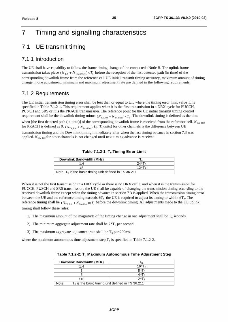
3GPP
35Release 8 3GPP TS 36.133 V8.9.0 (2010-03)
7 Timing and signalling characteristics
7.1 UE transmit timing
7.1.1 Introduction The UE shall have capability to follow the frame timing change of the connected eNode B. The uplink frame transmission takes place soffsetTA TA )( TNN ´+ before the reception of the first detected path (in time) of the corresponding downlink frame from the reference cell UE initial transmit timing accuracy, maximum amount of timing change in one adjustment, minimum and maximum adjustment rate are defined in the following requirements.
7.1.2 Requirements The UE initial transmission timing error shall be less than or equal to ±Te where the timing error limit value Te is specified in Table 7.1.2-1. This requirement applies when it is the first transmission in a DRX cycle for PUCCH, PUSCH and SRS or it is the PRACH transmission. The reference point for the UE initial transmit timing control requirement shall be the downlink timing minus
soffsetTA TA_Ref )( TNN ´+ . The downlink timing is defined as the time when [the first detected path (in time)] of the corresponding downlink frame is received from the reference cell. NTA_Ref for PRACH is defined as 0. )( offsetTA TA_Ref NN + (in Ts units) for other channels is the difference between UE transmission timing and the Downlink timing immediately after when the last timing advance in section 7.3 was applied. NTA_Ref for other channels is not changed until next timing advance is received.
Table 7.1.2-1: Te Timing Error Limit
Downlink Bandwidth (MHz) Te_ 1.4 24*TS ≥3 12*TS
Note: TS is the basic timing unit defined in TS 36.211
When it is not the first transmission in a DRX cycle or there is no DRX cycle, and when it is the transmission for PUCCH, PUSCH and SRS transmission, the UE shall be capable of changing the transmission timing according to the received downlink frame except when the timing advance in section 7.3 is applied. When the transmission timing error between the UE and the reference timing exceeds ±Te the UE is required to adjust its timing to within ±Te. The reference timing shall be
soffsetTA TA_Ref )( TNN ´+ before the downlink timing. All adjustments made to the UE uplink timing shall follow these rules:
1) The maximum amount of the magnitude of the timing change in one adjustment shall be Tq seconds.
2) The minimum aggregate adjustment rate shall be 7*TS per second.
3) The maximum aggregate adjustment rate shall be Tq per 200ms.
where the maximum autonomous time adjustment step Tq is specified in Table 7.1.2-2.
Table 7.1.2-2: Tq Maximum Autonomous Time Adjustment Step
Downlink Bandwidth (MHz) Tq_ 1.4 16*TS 3 8*TS 5 4*TS
³10 2*TS Note: TS is the basic timing unit defined in TS 36.211
3GPP
36Release 8 3GPP TS 36.133 V8.9.0 (2010-03)
7.2 UE timer accuracy
7.2.1 Introduction UE timers are used in different protocol entities to control the UE behaviour.
7.2.2 Requirements For UE timers specified in section 7.3 in [2], UE shall comply with the timer accuracies according to Table 7.2.2-1.
The requirements are only related to the actual timing measurements internally in the UE. They do not include the following:
- Inaccuracy in the start and stop conditions of a timer (e.g. UE reaction time to detect that start and stop conditions of a timer is fulfilled), or
- Inaccuracies due to restrictions in observability of start and stop conditions of a UE timer (e.g. TTI alignment when UE sends messages at timer expiry).
Table 7.2.2-1
Timer value [s] Accuracy timer value < [4] ± [0.1s] timer value ³ [4] ± [2.5%]
7.3 Timing Advance
7.3.1 Introduction The timing advance is initiated from E-UTRAN with MAC message that implies and adjustment of the timing advance, see 3GPP TS 36.321 [17] section 5.2.
7.3.2 Requirements
7.3.2.1 Timing Advance adjustment delay
UE shall adjust the timing of its uplink transmission timing at sub-frame n+6 for a timing advancement command received in sub-frame n.
7.3.2.2 Timing Advance adjustment accuracy
The UE shall adjust the timing of its transmissions with an relative accuracy better than or equal to [±4* TS seconds] to the signalled timing advance value compared to the timing of preceding uplink transmission. The timing advance command is expressed in multiples of 16* TS and is relative to the current uplink timing.
7.4 Cell phase synchronization accuracy (TDD)
7.4.1 Definition Cell phase synchronization accuracy is defined as the maximum absolute deviation in frame start timing between any pair of cells on the same frequency that have overlapping coverage areas.
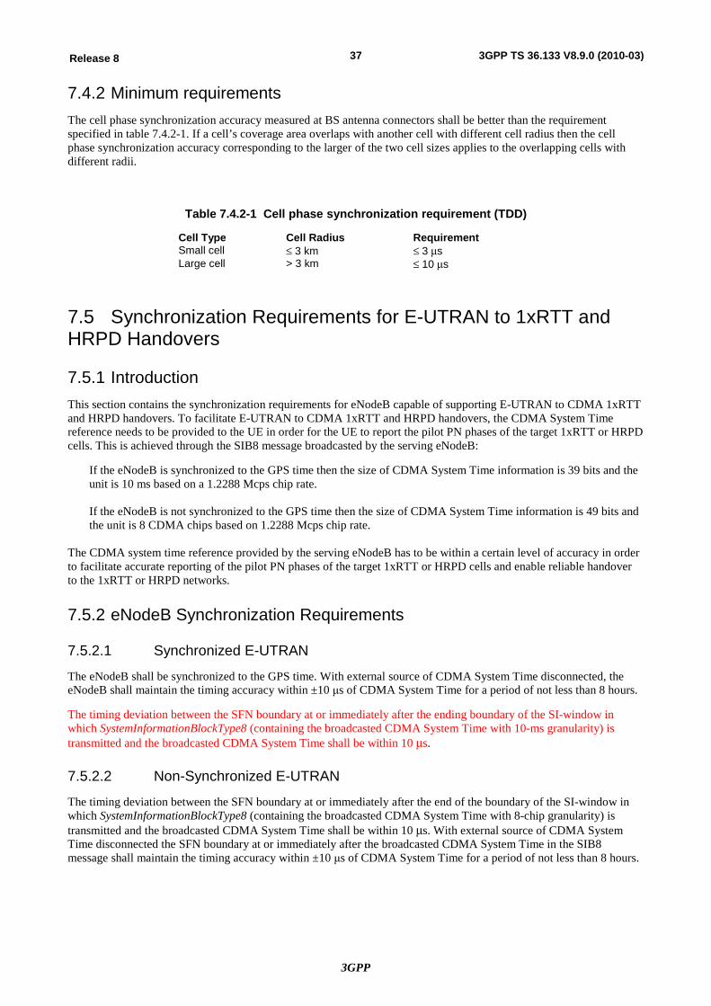
3GPP
37Release 8 3GPP TS 36.133 V8.9.0 (2010-03)
7.4.2 Minimum requirements The cell phase synchronization accuracy measured at BS antenna connectors shall be better than the requirement specified in table 7.4.2-1. If a cell’s coverage area overlaps with another cell with different cell radius then the cell phase synchronization accuracy corresponding to the larger of the two cell sizes applies to the overlapping cells with different radii.
Table 7.4.2-1 Cell phase synchronization requirement (TDD)
Cell Type Cell Radius Requirement Small cell £ 3 km £ 3 ms Large cell > 3 km £ 10 ms
7.5 Synchronization Requirements for E-UTRAN to 1xRTT and HRPD Handovers
7.5.1 Introduction This section contains the synchronization requirements for eNodeB capable of supporting E-UTRAN to CDMA 1xRTT and HRPD handovers. To facilitate E-UTRAN to CDMA 1xRTT and HRPD handovers, the CDMA System Time reference needs to be provided to the UE in order for the UE to report the pilot PN phases of the target 1xRTT or HRPD cells. This is achieved through the SIB8 message broadcasted by the serving eNodeB:
If the eNodeB is synchronized to the GPS time then the size of CDMA System Time information is 39 bits and the unit is 10 ms based on a 1.2288 Mcps chip rate. If the eNodeB is not synchronized to the GPS time then the size of CDMA System Time information is 49 bits and the unit is 8 CDMA chips based on 1.2288 Mcps chip rate.
The CDMA system time reference provided by the serving eNodeB has to be within a certain level of accuracy in order to facilitate accurate reporting of the pilot PN phases of the target 1xRTT or HRPD cells and enable reliable handover to the 1xRTT or HRPD networks.
7.5.2 eNodeB Synchronization Requirements
7.5.2.1 Synchronized E-UTRAN
The eNodeB shall be synchronized to the GPS time. With external source of CDMA System Time disconnected, the eNodeB shall maintain the timing accuracy within ±10 μs of CDMA System Time for a period of not less than 8 hours.
The timing deviation between the SFN boundary at or immediately after the ending boundary of the SI-window in which SystemInformationBlockType8 (containing the broadcasted CDMA System Time with 10-ms granularity) is transmitted and the broadcasted CDMA System Time shall be within 10 ms.
7.5.2.2 Non-Synchronized E-UTRAN
The timing deviation between the SFN boundary at or immediately after the end of the boundary of the SI-window in which SystemInformationBlockType8 (containing the broadcasted CDMA System Time with 8-chip granularity) is transmitted and the broadcasted CDMA System Time shall be within 10 ms. With external source of CDMA System Time disconnected the SFN boundary at or immediately after the broadcasted CDMA System Time in the SIB8 message shall maintain the timing accuracy within ±10 μs of CDMA System Time for a period of not less than 8 hours.
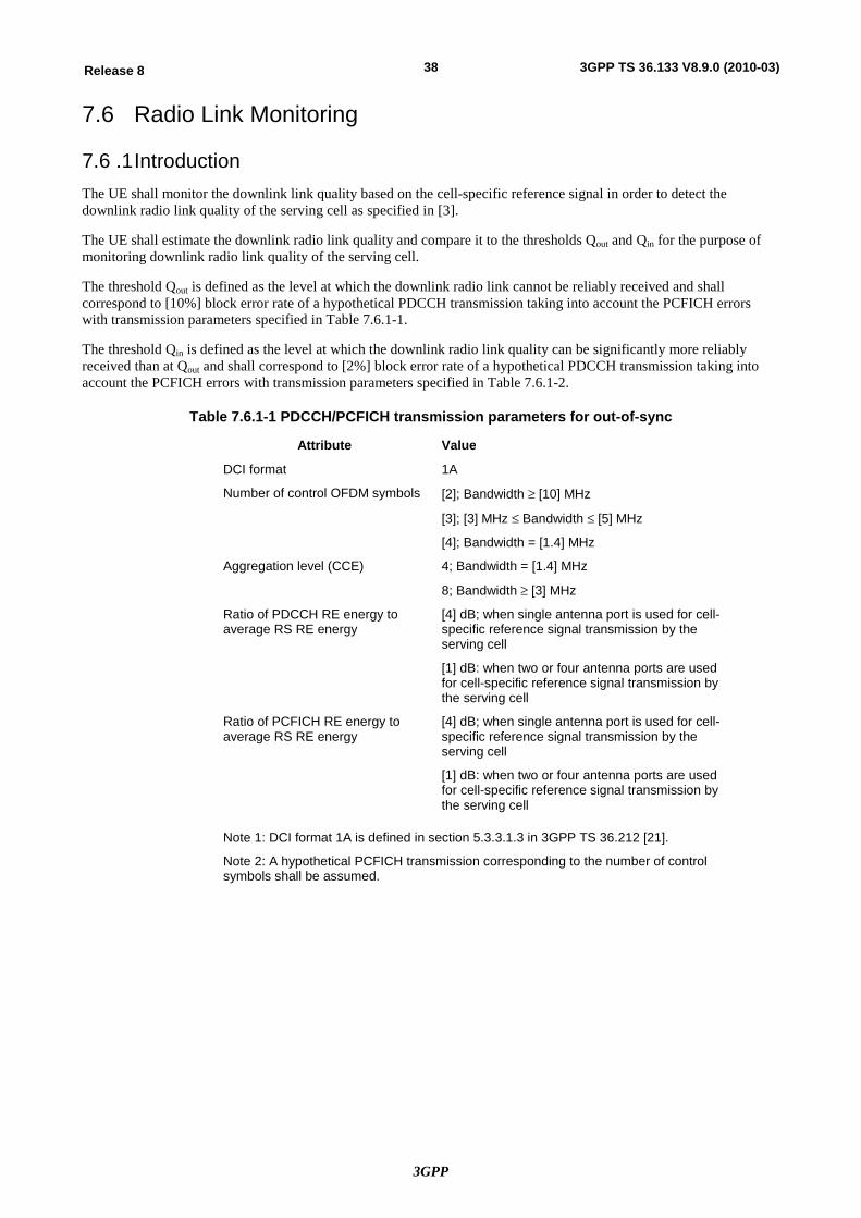
3GPP
38Release 8 3GPP TS 36.133 V8.9.0 (2010-03)
7.6 Radio Link Monitoring
7.6 .1 Introduction The UE shall monitor the downlink link quality based on the cell-specific reference signal in order to detect the downlink radio link quality of the serving cell as specified in [3].
The UE shall estimate the downlink radio link quality and compare it to the thresholds Qout and Qin for the purpose of monitoring downlink radio link quality of the serving cell.
The threshold Qout is defined as the level at which the downlink radio link cannot be reliably received and shall correspond to [10%] block error rate of a hypothetical PDCCH transmission taking into account the PCFICH errors with transmission parameters specified in Table 7.6.1-1.
The threshold Qin is defined as the level at which the downlink radio link quality can be significantly more reliably received than at Qout and shall correspond to [2%] block error rate of a hypothetical PDCCH transmission taking into account the PCFICH errors with transmission parameters specified in Table 7.6.1-2.
Table 7.6.1-1 PDCCH/PCFICH transmission parameters for out-of-sync
Attribute Value
DCI format 1A
Number of control OFDM symbols
[2]; Bandwidth ³ [10] MHz
[3]; [3] MHz £ Bandwidth £ [5] MHz
[4]; Bandwidth = [1.4] MHz
Aggregation level (CCE) 4; Bandwidth = [1.4] MHz
8; Bandwidth ³ [3] MHz
Ratio of PDCCH RE energy to average RS RE energy
[4] dB; when single antenna port is used for cell-specific reference signal transmission by the serving cell
[1] dB: when two or four antenna ports are used for cell-specific reference signal transmission by the serving cell
Ratio of PCFICH RE energy to average RS RE energy
[4] dB; when single antenna port is used for cell-specific reference signal transmission by the serving cell
[1] dB: when two or four antenna ports are used for cell-specific reference signal transmission by the serving cell
Note 1: DCI format 1A is defined in section 5.3.3.1.3 in 3GPP TS 36.212 [21].
Note 2: A hypothetical PCFICH transmission corresponding to the number of control symbols shall be assumed.
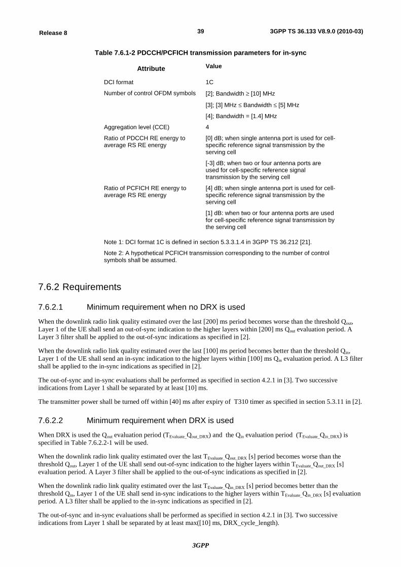
3GPP
39Release 8 3GPP TS 36.133 V8.9.0 (2010-03)
Table 7.6.1-2 PDCCH/PCFICH transmission parameters for in-sync
Attribute Value
DCI format 1C
Number of control OFDM symbols [2]; Bandwidth ³ [10] MHz
[3]; [3] MHz £ Bandwidth £ [5] MHz
[4]; Bandwidth = [1.4] MHz
Aggregation level (CCE) 4
Ratio of PDCCH RE energy to average RS RE energy
[0] dB; when single antenna port is used for cell-specific reference signal transmission by the serving cell
[-3] dB; when two or four antenna ports are used for cell-specific reference signal transmission by the serving cell
Ratio of PCFICH RE energy to average RS RE energy
[4] dB; when single antenna port is used for cell-specific reference signal transmission by the serving cell
[1] dB: when two or four antenna ports are used for cell-specific reference signal transmission by the serving cell
Note 1: DCI format 1C is defined in section 5.3.3.1.4 in 3GPP TS 36.212 [21].
Note 2: A hypothetical PCFICH transmission corresponding to the number of control symbols shall be assumed.
7.6.2 Requirements
7.6.2.1 Minimum requirement when no DRX is used
When the downlink radio link quality estimated over the last [200] ms period becomes worse than the threshold Qout, Layer 1 of the UE shall send an out-of-sync indication to the higher layers within [200] ms Qout evaluation period. A Layer 3 filter shall be applied to the out-of-sync indications as specified in [2].
When the downlink radio link quality estimated over the last [100] ms period becomes better than the threshold Qin, Layer 1 of the UE shall send an in-sync indication to the higher layers within [100] ms Qin evaluation period. A L3 filter shall be applied to the in-sync indications as specified in [2].
The out-of-sync and in-sync evaluations shall be performed as specified in section 4.2.1 in [3]. Two successive indications from Layer 1 shall be separated by at least [10] ms.
The transmitter power shall be turned off within [40] ms after expiry of T310 timer as specified in section 5.3.11 in [2].
7.6.2.2 Minimum requirement when DRX is used
When DRX is used the Qout evaluation period (TEvaluate_Qout_DRX) and the Qin evaluation period (TEvaluate_Qin_DRX) is specified in Table 7.6.2.2-1 will be used.
When the downlink radio link quality estimated over the last TEvaluate_Qout_DRX [s] period becomes worse than the threshold Qout, Layer 1 of the UE shall send out-of-sync indication to the higher layers within TEvaluate_Qout_DRX [s] evaluation period. A Layer 3 filter shall be applied to the out-of-sync indications as specified in [2].
When the downlink radio link quality estimated over the last TEvaluate_Qin_DRX [s] period becomes better than the threshold Qin, Layer 1 of the UE shall send in-sync indications to the higher layers within TEvaluate_Qin_DRX [s] evaluation period. A L3 filter shall be applied to the in-sync indications as specified in [2].
The out-of-sync and in-sync evaluations shall be performed as specified in section 4.2.1 in [3]. Two successive indications from Layer 1 shall be separated by at least max([10] ms, DRX_cycle_length).
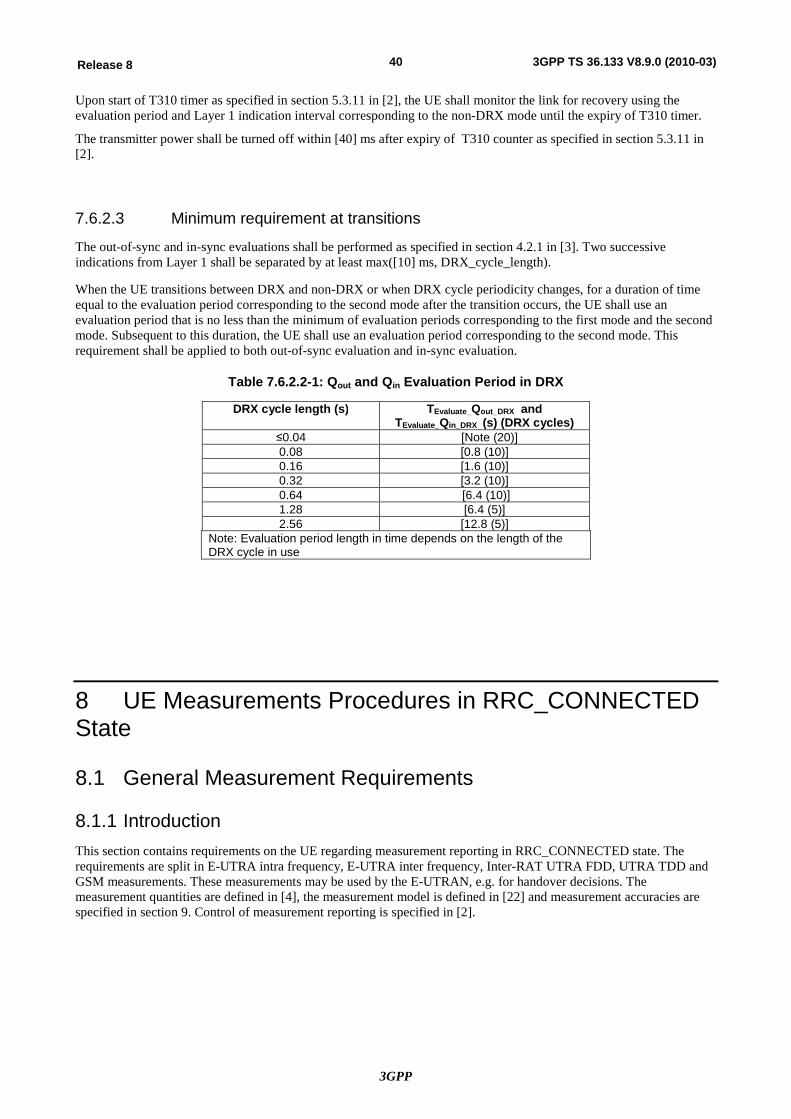
3GPP
40Release 8 3GPP TS 36.133 V8.9.0 (2010-03)
Upon start of T310 timer as specified in section 5.3.11 in [2], the UE shall monitor the link for recovery using the evaluation period and Layer 1 indication interval corresponding to the non-DRX mode until the expiry of T310 timer.
The transmitter power shall be turned off within [40] ms after expiry of T310 counter as specified in section 5.3.11 in [2].
7.6.2.3 Minimum requirement at transitions
The out-of-sync and in-sync evaluations shall be performed as specified in section 4.2.1 in [3]. Two successive indications from Layer 1 shall be separated by at least max([10] ms, DRX_cycle_length).
When the UE transitions between DRX and non-DRX or when DRX cycle periodicity changes, for a duration of time equal to the evaluation period corresponding to the second mode after the transition occurs, the UE shall use an evaluation period that is no less than the minimum of evaluation periods corresponding to the first mode and the second mode. Subsequent to this duration, the UE shall use an evaluation period corresponding to the second mode. This requirement shall be applied to both out-of-sync evaluation and in-sync evaluation.
Table 7.6.2.2-1: Qout and Qin Evaluation Period in DRX
DRX cycle length (s) TEvaluate_Qout_DRX and TEvaluate_Qin_DRX (s) (DRX cycles)
≤0.04 [Note (20)] 0.08 [0.8 (10)] 0.16 [1.6 (10)] 0.32 [3.2 (10)] 0.64 [6.4 (10)] 1.28 [6.4 (5)] 2.56 [12.8 (5)]
Note: Evaluation period length in time depends on the length of the DRX cycle in use
8 UE Measurements Procedures in RRC_CONNECTED State
8.1 General Measurement Requirements
8.1.1 Introduction This section contains requirements on the UE regarding measurement reporting in RRC_CONNECTED state. The requirements are split in E-UTRA intra frequency, E-UTRA inter frequency, Inter-RAT UTRA FDD, UTRA TDD and GSM measurements. These measurements may be used by the E-UTRAN, e.g. for handover decisions. The measurement quantities are defined in [4], the measurement model is defined in [22] and measurement accuracies are specified in section 9. Control of measurement reporting is specified in [2].
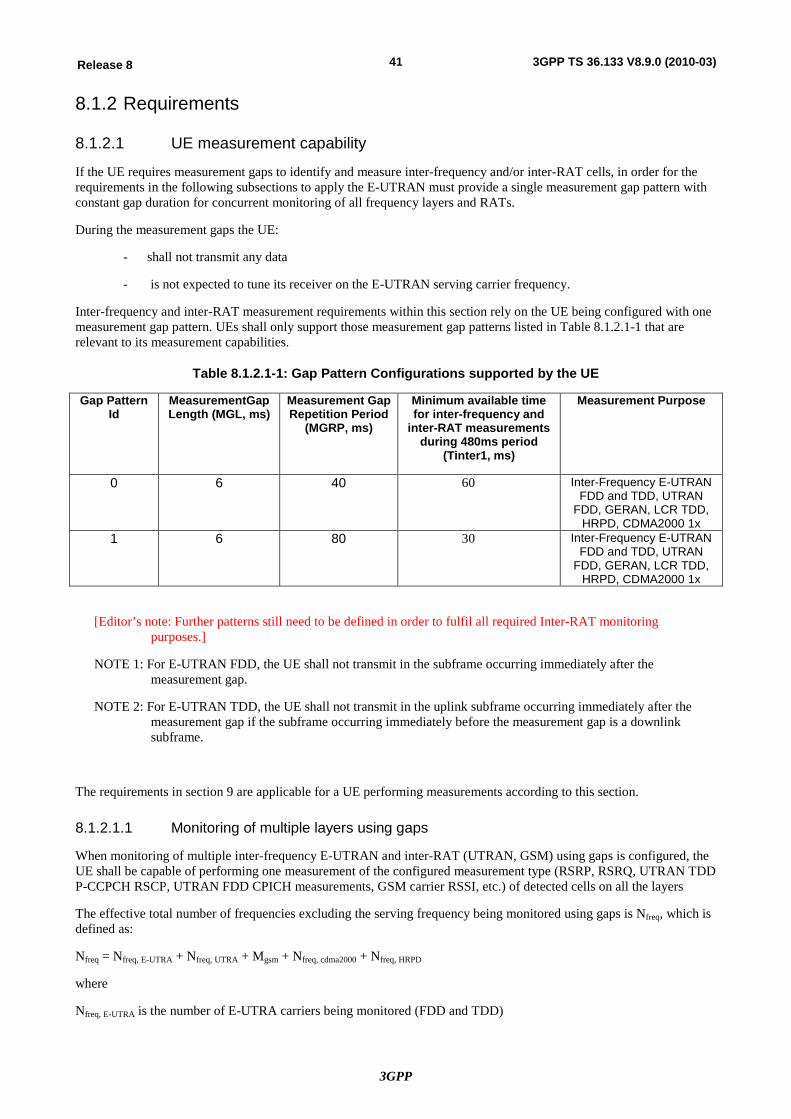
3GPP
41Release 8 3GPP TS 36.133 V8.9.0 (2010-03)
8.1.2 Requirements
8.1.2.1 UE measurement capability
If the UE requires measurement gaps to identify and measure inter-frequency and/or inter-RAT cells, in order for the requirements in the following subsections to apply the E-UTRAN must provide a single measurement gap pattern with constant gap duration for concurrent monitoring of all frequency layers and RATs.
During the measurement gaps the UE:
- shall not transmit any data
- is not expected to tune its receiver on the E-UTRAN serving carrier frequency.
Inter-frequency and inter-RAT measurement requirements within this section rely on the UE being configured with one measurement gap pattern. UEs shall only support those measurement gap patterns listed in Table 8.1.2.1-1 that are relevant to its measurement capabilities.
Table 8.1.2.1-1: Gap Pattern Configurations supported by the UE
Gap Pattern Id
MeasurementGap Length (MGL, ms)
Measurement Gap Repetition Period
(MGRP, ms)
Minimum available time for inter-frequency and
inter-RAT measurements during 480ms period
(Tinter1, ms)
Measurement Purpose
0 6 40 60 Inter-Frequency E-UTRAN FDD and TDD, UTRAN
FDD, GERAN, LCR TDD, HRPD, CDMA2000 1x
1 6 80 30 Inter-Frequency E-UTRAN FDD and TDD, UTRAN
FDD, GERAN, LCR TDD, HRPD, CDMA2000 1x
[Editor’s note: Further patterns still need to be defined in order to fulfil all required Inter-RAT monitoring purposes.]
NOTE 1: For E-UTRAN FDD, the UE shall not transmit in the subframe occurring immediately after the measurement gap.
NOTE 2: For E-UTRAN TDD, the UE shall not transmit in the uplink subframe occurring immediately after the measurement gap if the subframe occurring immediately before the measurement gap is a downlink subframe.
The requirements in section 9 are applicable for a UE performing measurements according to this section.
8.1.2.1.1 Monitoring of multiple layers using gaps
When monitoring of multiple inter-frequency E-UTRAN and inter-RAT (UTRAN, GSM) using gaps is configured, the UE shall be capable of performing one measurement of the configured measurement type (RSRP, RSRQ, UTRAN TDD P-CCPCH RSCP, UTRAN FDD CPICH measurements, GSM carrier RSSI, etc.) of detected cells on all the layers
The effective total number of frequencies excluding the serving frequency being monitored using gaps is Nfreq, which is defined as:
Nfreq = Nfreq, E-UTRA + Nfreq, UTRA + Mgsm + Nfreq, cdma2000 + Nfreq, HRPD
where
Nfreq, E-UTRA is the number of E-UTRA carriers being monitored (FDD and TDD)
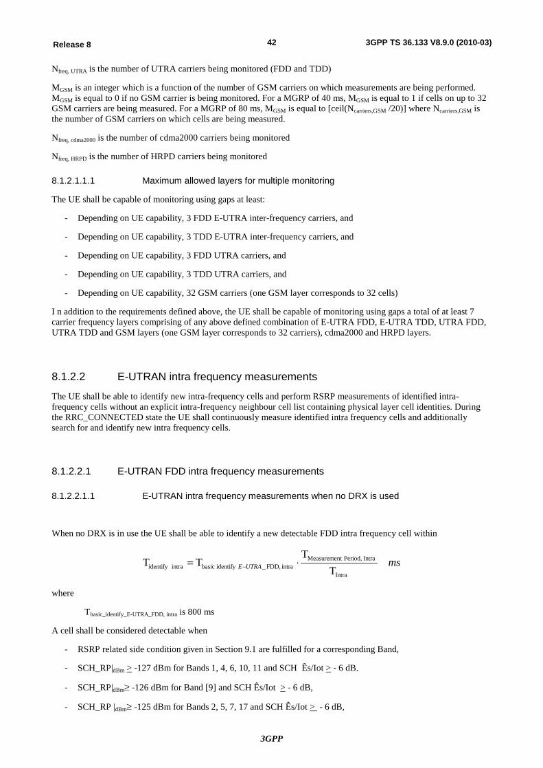
3GPP
42Release 8 3GPP TS 36.133 V8.9.0 (2010-03)
Nfreq, UTRA is the number of UTRA carriers being monitored (FDD and TDD)
MGSM is an integer which is a function of the number of GSM carriers on which measurements are being performed. MGSM is equal to 0 if no GSM carrier is being monitored. For a MGRP of 40 ms, MGSM is equal to 1 if cells on up to 32 GSM carriers are being measured. For a MGRP of 80 ms, MGSM is equal to [ceil(Ncarriers,GSM /20)] where Ncarriers,GSM is the number of GSM carriers on which cells are being measured.
Nfreq, cdma2000 is the number of cdma2000 carriers being monitored
Nfreq, HRPD is the number of HRPD carriers being monitored
8.1.2.1.1.1 Maximum allowed layers for multiple monitoring
The UE shall be capable of monitoring using gaps at least:
- Depending on UE capability, 3 FDD E-UTRA inter-frequency carriers, and
- Depending on UE capability, 3 TDD E-UTRA inter-frequency carriers, and
- Depending on UE capability, 3 FDD UTRA carriers, and
- Depending on UE capability, 3 TDD UTRA carriers, and
- Depending on UE capability, 32 GSM carriers (one GSM layer corresponds to 32 cells)
I n addition to the requirements defined above, the UE shall be capable of monitoring using gaps a total of at least 7 carrier frequency layers comprising of any above defined combination of E-UTRA FDD, E-UTRA TDD, UTRA FDD, UTRA TDD and GSM layers (one GSM layer corresponds to 32 carriers), cdma2000 and HRPD layers.
8.1.2.2 E-UTRAN intra frequency measurements
The UE shall be able to identify new intra-frequency cells and perform RSRP measurements of identified intra-frequency cells without an explicit intra-frequency neighbour cell list containing physical layer cell identities. During the RRC_CONNECTED state the UE shall continuously measure identified intra frequency cells and additionally search for and identify new intra frequency cells.
8.1.2.2.1 E-UTRAN FDD intra frequency measurements
8.1.2.2.1.1 E-UTRAN intra frequency measurements when no DRX is used
When no DRX is in use the UE shall be able to identify a new detectable FDD intra frequency cell within
msUTRAEIntra
Intra Period,tMeasuremenintra FDD,_identifybasicintra identify T
TTT ×= -
where
Tbasic_identify_E-UTRA_FDD, intra is 800 ms
A cell shall be considered detectable when
- RSRP related side condition given in Section 9.1 are fulfilled for a corresponding Band,
- SCH_RP|dBm > -127 dBm for Bands 1, 4, 6, 10, 11 and SCH Ês/Iot > - 6 dB.
- SCH_RP|dBm³ -126 dBm for Band [9] and SCH Ês/Iot > - 6 dB,
- SCH_RP |dBm³ -125 dBm for Bands 2, 5, 7, 17 and SCH Ês/Iot > - 6 dB,
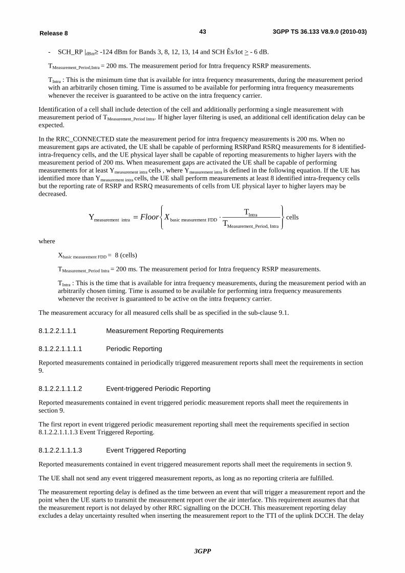
3GPP
43Release 8 3GPP TS 36.133 V8.9.0 (2010-03)
- SCH_RP |dBm³ -124 dBm for Bands 3, 8, 12, 13, 14 and SCH Ês/Iot > - 6 dB.
TMeasurement_Period,Intra = 200 ms. The measurement period for Intra frequency RSRP measurements.
TIntra : This is the minimum time that is available for intra frequency measurements, during the measurement period with an arbitrarily chosen timing. Time is assumed to be available for performing intra frequency measurements whenever the receiver is guaranteed to be active on the intra frequency carrier.
Identification of a cell shall include detection of the cell and additionally performing a single measurement with measurement period of TMeasurement_Period Intra. If higher layer filtering is used, an additional cell identification delay can be expected.
In the RRC_CONNECTED state the measurement period for intra frequency measurements is 200 ms. When no measurement gaps are activated, the UE shall be capable of performing RSRPand RSRQ measurements for 8 identified-intra-frequency cells, and the UE physical layer shall be capable of reporting measurements to higher layers with the measurement period of 200 ms. When measurement gaps are activated the UE shall be capable of performing measurements for at least Ymeasurement intra cells , where Ymeasurement intra is defined in the following equation. If the UE has identified more than Ymeasurement intra cells, the UE shall perform measurements at least 8 identified intra-frequency cells but the reporting rate of RSRP and RSRQ measurements of cells from UE physical layer to higher layers may be decreased.
ïþ
ïýü
ïî
ïíì
×=Intra t_Period,Measuremen
IntraFDDtmeasuremenbasicintra tmeasuremen T
TY XFloor cells
where
Xbasic measurement FDD = 8 (cells)
TMeasurement_Period Intra = 200 ms. The measurement period for Intra frequency RSRP measurements.
TIntra : This is the time that is available for intra frequency measurements, during the measurement period with an arbitrarily chosen timing. Time is assumed to be available for performing intra frequency measurements whenever the receiver is guaranteed to be active on the intra frequency carrier.
The measurement accuracy for all measured cells shall be as specified in the sub-clause 9.1.
8.1.2.2.1.1.1 Measurement Reporting Requirements
8.1.2.2.1.1.1.1 Periodic Reporting
Reported measurements contained in periodically triggered measurement reports shall meet the requirements in section 9.
8.1.2.2.1.1.1.2 Event-triggered Periodic Reporting
Reported measurements contained in event triggered periodic measurement reports shall meet the requirements in section 9.
The first report in event triggered periodic measurement reporting shall meet the requirements specified in section 8.1.2.2.1.1.1.3 Event Triggered Reporting.
8.1.2.2.1.1.1.3 Event Triggered Reporting
Reported measurements contained in event triggered measurement reports shall meet the requirements in section 9.
The UE shall not send any event triggered measurement reports, as long as no reporting criteria are fulfilled.
The measurement reporting delay is defined as the time between an event that will trigger a measurement report and the point when the UE starts to transmit the measurement report over the air interface. This requirement assumes that that the measurement report is not delayed by other RRC signalling on the DCCH. This measurement reporting delay excludes a delay uncertainty resulted when inserting the measurement report to the TTI of the uplink DCCH. The delay
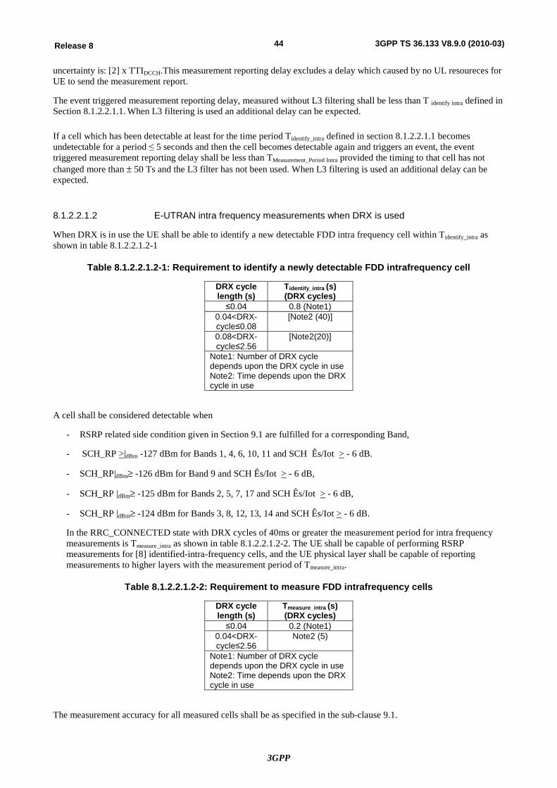
3GPP
44Release 8 3GPP TS 36.133 V8.9.0 (2010-03)
uncertainty is: [2] x TTIDCCH.This measurement reporting delay excludes a delay which caused by no UL resoureces for UE to send the measurement report.
The event triggered measurement reporting delay, measured without L3 filtering shall be less than T identify intra defined in Section 8.1.2.2.1.1. When L3 filtering is used an additional delay can be expected.
If a cell which has been detectable at least for the time period Tidentify_intra defined in section 8.1.2.2.1.1 becomes undetectable for a period ≤ 5 seconds and then the cell becomes detectable again and triggers an event, the event triggered measurement reporting delay shall be less than TMeasurement_Period Intra provided the timing to that cell has not changed more than ± 50 Ts and the L3 filter has not been used. When L3 filtering is used an additional delay can be expected.
8.1.2.2.1.2 E-UTRAN intra frequency measurements when DRX is used
When DRX is in use the UE shall be able to identify a new detectable FDD intra frequency cell within Tidentify_intra as shown in table 8.1.2.2.1.2-1
Table 8.1.2.2.1.2-1: Requirement to identify a newly detectable FDD intrafrequency cell
DRX cycle length (s)
Tidentify_intra (s) (DRX cycles)
≤0.04 0.8 (Note1) 0.04<DRX-cycle≤0.08
[Note2 (40)]
0.08<DRX-cycle≤2.56
[Note2(20)]
Note1: Number of DRX cycle depends upon the DRX cycle in use Note2: Time depends upon the DRX cycle in use
A cell shall be considered detectable when
- RSRP related side condition given in Section 9.1 are fulfilled for a corresponding Band,
- SCH_RP >|dBm -127 dBm for Bands 1, 4, 6, 10, 11 and SCH Ês/Iot > - 6 dB.
- SCH_RP|dBm³ -126 dBm for Band 9 and SCH Ês/Iot > - 6 dB,
- SCH_RP |dBm³ -125 dBm for Bands 2, 5, 7, 17 and SCH Ês/Iot > - 6 dB,
- SCH_RP |dBm³ -124 dBm for Bands 3, 8, 12, 13, 14 and SCH Ês/Iot > - 6 dB.
In the RRC_CONNECTED state with DRX cycles of 40ms or greater the measurement period for intra frequency measurements is Tmeasure_intra as shown in table 8.1.2.2.1.2-2. The UE shall be capable of performing RSRP measurements for [8] identified-intra-frequency cells, and the UE physical layer shall be capable of reporting measurements to higher layers with the measurement period of Tmeasure_intra.
Table 8.1.2.2.1.2-2: Requirement to measure FDD intrafrequency cells
DRX cycle length (s)
Tmeasure_intra (s) (DRX cycles)
≤0.04 0.2 (Note1) 0.04<DRX-cycle≤2.56
Note2 (5)
Note1: Number of DRX cycle depends upon the DRX cycle in use Note2: Time depends upon the DRX cycle in use
The measurement accuracy for all measured cells shall be as specified in the sub-clause 9.1.
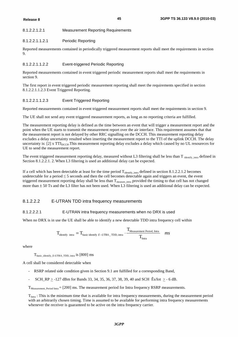
3GPP
45Release 8 3GPP TS 36.133 V8.9.0 (2010-03)
8.1.2.2.1.2.1 Measurement Reporting Requirements
8.1.2.2.1.1.2.1 Periodic Reporting
Reported measurements contained in periodically triggered measurement reports shall meet the requirements in section 9.
8.1.2.2.1.1.2.2 Event-triggered Periodic Reporting
Reported measurements contained in event triggered periodic measurement reports shall meet the requirements in section 9.
The first report in event triggered periodic measurement reporting shall meet the requirements specified in section 8.1.2.2.1.1.2.3 Event Triggered Reporting.
8.1.2.2.1.1.2.3 Event Triggered Reporting
Reported measurements contained in event triggered measurement reports shall meet the requirements in section 9.
The UE shall not send any event triggered measurement reports, as long as no reporting criteria are fulfilled.
The measurement reporting delay is defined as the time between an event that will trigger a measurement report and the point when the UE starts to transmit the measurement report over the air interface. This requirement assumes that that the measurement report is not delayed by other RRC signalling on the DCCH. This measurement reporting delay excludes a delay uncertainty resulted when inserting the measurement report to the TTI of the uplink DCCH. The delay uncertainty is: [2] x TTIDCCH.This measurement reporting delay excludes a delay which caused by no UL resoureces for UE to send the measurement report.
The event triggered measurement reporting delay, measured without L3 filtering shall be less than T identify_intra defined in Section 8.1.2.2.1. 2. When L3 filtering is used an additional delay can be expected.
If a cell which has been detectable at least for the time period Tidentify_intra defined in section 8.1.2.2.1.2 becomes undetectable for a period ≤ 5 seconds and then the cell becomes detectable again and triggers an event, the event triggered measurement reporting delay shall be less than Tmeasure_intra provided the timing to that cell has not changed more than ± 50 Ts and the L3 filter has not been used. When L3 filtering is used an additional delay can be expected.
8.1.2.2.2 E-UTRAN TDD intra frequency measurements
8.1.2.2.2.1 E-UTRAN intra frequency measurements when no DRX is used
When no DRX is in use the UE shall be able to identify a new detectable TDD intra frequency cell within
msUTRAEIntra
Intra Period,tMeasuremenintra TDD,_identifybasicintra identify T
TTT ×= -
where
Tbasic_identify_E-UTRA_TDD, intra is [800] ms
A cell shall be considered detectable when
- RSRP related side condition given in Section 9.1 are fulfilled for a corresponding Band,
- SCH_RP > -127 dBm for Bands 33, 34, 35, 36, 37, 38, 39, 40 and SCH Ês/Iot > - 6 dB.
TMeasurement_Period Intra = [200] ms. The measurement period for Intra frequency RSRP measurements.
TIntra : This is the minimum time that is available for intra frequency measurements, during the measurement period with an arbitrarily chosen timing. Time is assumed to be available for performing intra frequency measurements whenever the receiver is guaranteed to be active on the intra frequency carrier.
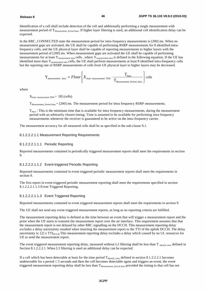
3GPP
46Release 8 3GPP TS 36.133 V8.9.0 (2010-03)
Identification of a cell shall include detection of the cell and additionally performing a single measurement with measurement period of TMeasurement_Period Intra. If higher layer filtering is used, an additional cell identification delay can be expected.
In the RRC_CONNECTED state the measurement period for intra frequency measurements is [200] ms. When no measurement gaps are activated, the UE shall be capable of performing RSRP measurements for 8 identified-intra-frequency cells, and the UE physical layer shall be capable of reporting measurements to higher layers with the measurement period of [200] ms. When measurement gaps are activated the UE shall be capable of performing measurements for at least Ymeasurement intra cells , where Ymeasurement intra is defined in the following equation. If the UE has identified more than Ymeasurement intra cells, the UE shall perform measurements at least 8 identified intra-frequency cells but the reporting rate of RSRP measurements of cells from UE physical layer to higher layers may be decreased.
ïþ
ïýü
ïî
ïíì
×=Intra t_Period,Measuremen
IntraTDDtmeasuremenbasicintra tmeasuremen T
TY XFloor cells
where
Xbasic measurement TDD = [8] (cells)
TMeasurement_Period Intra = [200] ms. The measurement period for Intra frequency RSRP measurements.
TIntra : This is the minimum time that is available for intra frequency measurements, during the measurement period with an arbitrarily chosen timing. Time is assumed to be available for performing intra frequency measurements whenever the receiver is guaranteed to be active on the intra frequency carrier.
The measurement accuracy for all measured cells shall be as specified in the sub-clause 9.1.
8.1.2.2.2.1.1 Measurement Reporting Requirements
8.1.2.2.2.1.1.1 Periodic Reporting
Reported measurements contained in periodically triggered measurement reports shall meet the requirements in section 9.
8.1.2.2.2.1.1.2 Event-triggered Periodic Reporting
Reported measurements contained in event triggered periodic measurement reports shall meet the requirements in section 9.
The first report in event triggered periodic measurement reporting shall meet the requirements specified in section 8.1.2.2.2.1.1.3 Event Triggered Reporting.
8.1.2.2.2.1.1.3 Event Triggered Reporting
Reported measurements contained in event triggered measurement reports shall meet the requirements in section 9.
The UE shall not send any event triggered measurement reports, as long as no reporting criteria are fulfilled.
The measurement reporting delay is defined as the time between an event that will trigger a measurement report and the point when the UE starts to transmit the measurement report over the air interface. This requirement assumes that that the measurement report is not delayed by other RRC signalling on the DCCH. This measurement reporting delay excludes a delay uncertainty resulted when inserting the measurement report to the TTI of the uplink DCCH. The delay uncertainty is: [2] x TTIDCCH.This measurement reporting delay excludes a delay which caused by no UL resources for UE to send the measurement report.
The event triggered measurement reporting delay, measured without L3 filtering shall be less than T identify intra defined in Section 8.1.2.2.2.1. When L3 filtering is used an additional delay can be expected.
If a cell which has been detectable at least for the time period Tidentify_intra defined in section 8.1.2.2.2.1 becomes undetectable for a period ≤ 5 seconds and then the cell becomes detectable again and triggers an event, the event triggered measurement reporting delay shall be less than TMeasurement_Period Intra provided the timing to that cell has not
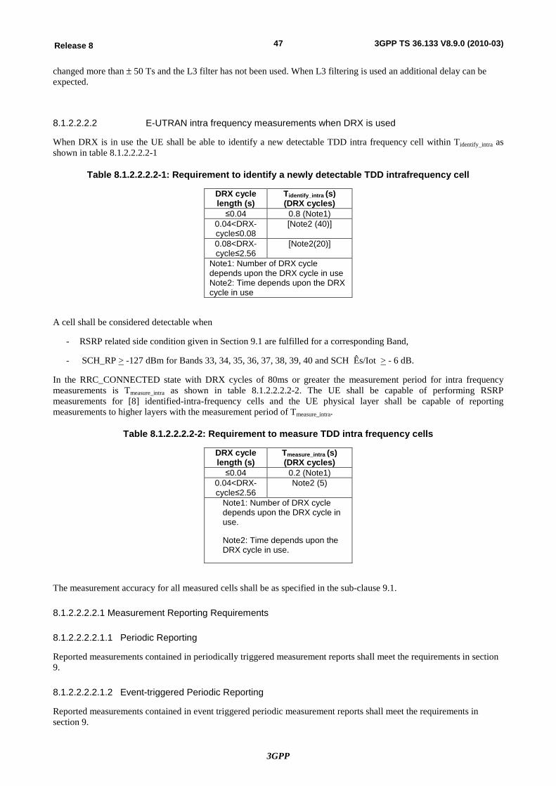
3GPP
47Release 8 3GPP TS 36.133 V8.9.0 (2010-03)
changed more than ± 50 Ts and the L3 filter has not been used. When L3 filtering is used an additional delay can be expected.
8.1.2.2.2.2 E-UTRAN intra frequency measurements when DRX is used
When DRX is in use the UE shall be able to identify a new detectable TDD intra frequency cell within Tidentify_intra as shown in table 8.1.2.2.2.2-1
Table 8.1.2.2.2.2-1: Requirement to identify a newly detectable TDD intrafrequency cell
DRX cycle length (s)
Tidentify_intra (s) (DRX cycles)
≤0.04 0.8 (Note1) 0.04<DRX-cycle≤0.08
[Note2 (40)]
0.08<DRX-cycle≤2.56
[Note2(20)]
Note1: Number of DRX cycle depends upon the DRX cycle in use Note2: Time depends upon the DRX cycle in use
A cell shall be considered detectable when
- RSRP related side condition given in Section 9.1 are fulfilled for a corresponding Band,
- SCH_RP > -127 dBm for Bands 33, 34, 35, 36, 37, 38, 39, 40 and SCH Ês/Iot > - 6 dB.
In the RRC_CONNECTED state with DRX cycles of 80ms or greater the measurement period for intra frequency measurements is Tmeasure_intra as shown in table 8.1.2.2.2.2-2. The UE shall be capable of performing RSRP measurements for [8] identified-intra-frequency cells and the UE physical layer shall be capable of reporting measurements to higher layers with the measurement period of Tmeasure_intra.
Table 8.1.2.2.2.2-2: Requirement to measure TDD intra frequency cells
DRX cycle length (s)
Tmeasure_intra (s) (DRX cycles)
≤0.04 0.2 (Note1) 0.04<DRX-cycle≤2.56
Note2 (5)
Note1: Number of DRX cycle depends upon the DRX cycle in use.
Note2: Time depends upon the DRX cycle in use.
The measurement accuracy for all measured cells shall be as specified in the sub-clause 9.1.
8.1.2.2.2.2.1 Measurement Reporting Requirements
8.1.2.2.2.2.1.1 Periodic Reporting
Reported measurements contained in periodically triggered measurement reports shall meet the requirements in section 9.
8.1.2.2.2.2.1.2 Event-triggered Periodic Reporting
Reported measurements contained in event triggered periodic measurement reports shall meet the requirements in section 9.
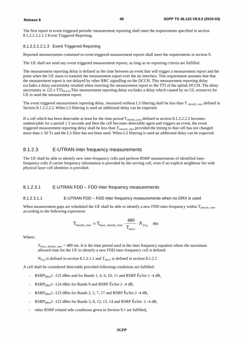
3GPP
48Release 8 3GPP TS 36.133 V8.9.0 (2010-03)
The first report in event triggered periodic measurement reporting shall meet the requirements specified in section 8.1.2.2.2.2.1.3 Event Triggered Reporting.
8.1.2.2.2.2.1.3 Event Triggered Reporting
Reported measurements contained in event triggered measurement reports shall meet the requirements in section 9.
The UE shall not send any event triggered measurement reports, as long as no reporting criteria are fulfilled.
The measurement reporting delay is defined as the time between an event that will trigger a measurement report and the point when the UE starts to transmit the measurement report over the air interface. This requirement assumes that that the measurement report is not delayed by other RRC signalling on the DCCH. This measurement reporting delay excludes a delay uncertainty resulted when inserting the measurement report to the TTI of the uplink DCCH. The delay uncertainty is: [2] x TTIDCCH.This measurement reporting delay excludes a delay which caused by no UL resources for UE to send the measurement report.
The event triggered measurement reporting delay, measured without L3 filtering shall be less than T identify_intra defined in Section 8.1.2.2.2.2. When L3 filtering is used an additional delay can be expected.
If a cell which has been detectable at least for the time period Tidentify_intra defined in section 8.1.2.2.2.2 becomes undetectable for a period ≤ 5 seconds and then the cell becomes detectable again and triggers an event, the event triggered measurement reporting delay shall be less than Tmeasure_intra provided the timing to that cell has not changed more than ± 50 Ts and the L3 filter has not been used. When L3 filtering is used an additional delay can be expected.
8.1.2.3 E-UTRAN inter frequency measurements
The UE shall be able to identify new inter-frequency cells and perform RSRP measurements of identified inter-frequency cells if carrier frequency information is provided by the serving cell, even if no explicit neighbour list with physical layer cell identities is provided.
8.1.2.3.1 E-UTRAN FDD – FDD inter frequency measurements
8.1.2.3.1.1 E-UTRAN FDD – FDD inter frequency measurements when no DRX is used
When measurement gaps are scheduled the UE shall be able to identify a new FDD inter-frequency within TIdentify_Inter according to the following expression:
msN freq××=Inter1
tify_InterBasic_IdennterIdentify_I T480TT
Where:
TBasic_Identify_Inter = 480 ms. It is the time period used in the inter frequency equation where the maximum allowed time for the UE to identify a new FDD inter-frequency cell is defined.
Nfreq is defined in section 8.1.2.1.1 and Tinter1 is defined in section 8.1.2.1
A cell shall be considered detectable provided following conditions are fulfilled:
- RSRP|dBm³ -125 dBm and for Bands 1, 4, 6, 10, 11 and RSRP Ês/Iot ³ -4 dB,
- RSRP|dBm³ -124 dBm for Bands 9 and RSRP Ês/Iot ³ -4 dB,
- RSRP|dBm³ -123 dBm for Bands 2, 5, 7, 17 and RSRP Ês/Iot ³ -4 dB,
- RSRP|dBm³ -122 dBm for Bands 3, 8, 12, 13, 14 and RSRP Ês/Iot ³ -4 dB,
- other RSRP related side conditions given in Section 9.1 are fulfilled,
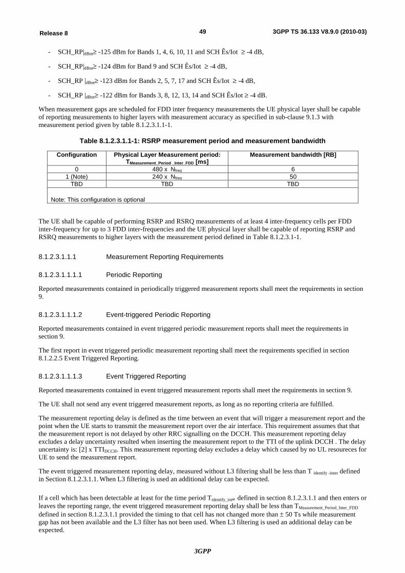
3GPP
49Release 8 3GPP TS 36.133 V8.9.0 (2010-03)
- SCH_RP|dBm³ -125 dBm for Bands 1, 4, 6, 10, 11 and SCH Ês/Iot ³ -4 dB,
- SCH_RP|dBm³ -124 dBm for Band 9 and SCH Ês/Iot ³ -4 dB,
- SCH_RP |dBm³ -123 dBm for Bands 2, 5, 7, 17 and SCH Ês/Iot ³ -4 dB,
- SCH_RP |dBm³ -122 dBm for Bands 3, 8, 12, 13, 14 and SCH Ês/Iot ³ -4 dB.
When measurement gaps are scheduled for FDD inter frequency measurements the UE physical layer shall be capable of reporting measurements to higher layers with measurement accuracy as specified in sub-clause 9.1.3 with measurement period given by table 8.1.2.3.1.1-1.
Table 8.1.2.3.1.1-1: RSRP measurement period and measurement bandwidth
Configuration Physical Layer Measurement period: TMeasurement_Period _Inter_FDD [ms]
Measurement bandwidth [RB]
0 480 x Nfreq 6 1 (Note) 240 x Nfreq 50
TBD TBD TBD
Note: This configuration is optional
The UE shall be capable of performing RSRP and RSRQ measurements of at least 4 inter-frequency cells per FDD inter-frequency for up to 3 FDD inter-frequencies and the UE physical layer shall be capable of reporting RSRP and RSRQ measurements to higher layers with the measurement period defined in Table 8.1.2.3.1-1.
8.1.2.3.1.1.1 Measurement Reporting Requirements
8.1.2.3.1.1.1.1 Periodic Reporting
Reported measurements contained in periodically triggered measurement reports shall meet the requirements in section 9.
8.1.2.3.1.1.1.2 Event-triggered Periodic Reporting
Reported measurements contained in event triggered periodic measurement reports shall meet the requirements in section 9.
The first report in event triggered periodic measurement reporting shall meet the requirements specified in section 8.1.2.2.5 Event Triggered Reporting.
8.1.2.3.1.1.1.3 Event Triggered Reporting
Reported measurements contained in event triggered measurement reports shall meet the requirements in section 9.
The UE shall not send any event triggered measurement reports, as long as no reporting criteria are fulfilled.
The measurement reporting delay is defined as the time between an event that will trigger a measurement report and the point when the UE starts to transmit the measurement report over the air interface. This requirement assumes that that the measurement report is not delayed by other RRC signalling on the DCCH. This measurement reporting delay excludes a delay uncertainty resulted when inserting the measurement report to the TTI of the uplink DCCH . The delay uncertainty is: [2] x TTIDCCH. This measurement reporting delay excludes a delay which caused by no UL resoureces for UE to send the measurement report.
The event triggered measurement reporting delay, measured without L3 filtering shall be less than T identify -inter defined in Section 8.1.2.3.1.1. When L3 filtering is used an additional delay can be expected.
If a cell which has been detectable at least for the time period Tidentify_inter defined in section 8.1.2.3.1.1 and then enters or leaves the reporting range, the event triggered measurement reporting delay shall be less than TMeasurement_Period_Inter_FDD defined in section 8.1.2.3.1.1 provided the timing to that cell has not changed more than ± 50 Ts while measurement gap has not been available and the L3 filter has not been used. When L3 filtering is used an additional delay can be expected.
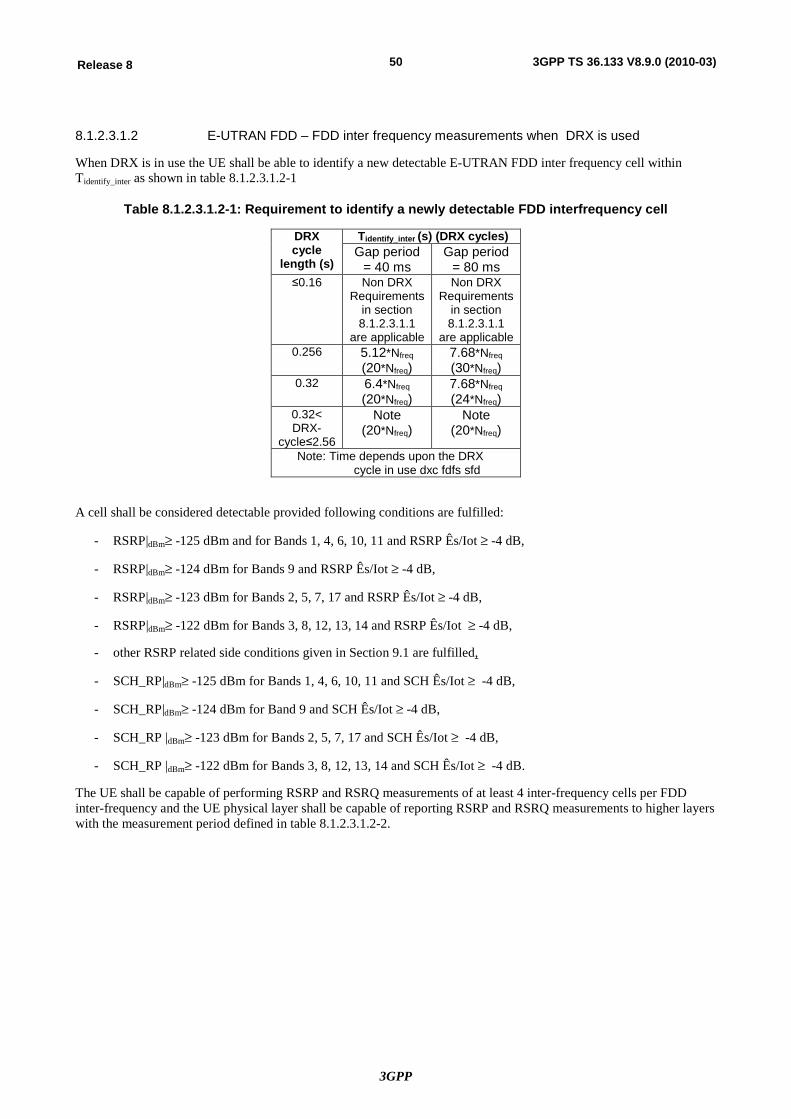
3GPP
50Release 8 3GPP TS 36.133 V8.9.0 (2010-03)
8.1.2.3.1.2 E-UTRAN FDD – FDD inter frequency measurements when DRX is used
When DRX is in use the UE shall be able to identify a new detectable E-UTRAN FDD inter frequency cell within Tidentify_inter as shown in table 8.1.2.3.1.2-1
Table 8.1.2.3.1.2-1: Requirement to identify a newly detectable FDD interfrequency cell
DRX cycle
length (s)
Tidentify_inter (s) (DRX cycles) Gap period
= 40 ms Gap period
= 80 ms ≤0.16 Non DRX
Requirements in section 8.1.2.3.1.1
are applicable
Non DRX Requirements
in section 8.1.2.3.1.1
are applicable 0.256 5.12*Nfreq
(20*Nfreq) 7.68*Nfreq (30*Nfreq)
0.32 6.4*Nfreq (20*Nfreq)
7.68*Nfreq (24*Nfreq)
0.32< DRX-
cycle≤2.56
Note (20*Nfreq)
Note (20*Nfreq)
Note: Time depends upon the DRX cycle in use dxc fdfs sfd
A cell shall be considered detectable provided following conditions are fulfilled:
- RSRP|dBm³ -125 dBm and for Bands 1, 4, 6, 10, 11 and RSRP Ês/Iot ³ -4 dB,
- RSRP|dBm³ -124 dBm for Bands 9 and RSRP Ês/Iot ³ -4 dB,
- RSRP|dBm³ -123 dBm for Bands 2, 5, 7, 17 and RSRP Ês/Iot ³ -4 dB,
- RSRP|dBm³ -122 dBm for Bands 3, 8, 12, 13, 14 and RSRP Ês/Iot ³ -4 dB,
- other RSRP related side conditions given in Section 9.1 are fulfilled,
- SCH_RP|dBm³ -125 dBm for Bands 1, 4, 6, 10, 11 and SCH Ês/Iot ³ -4 dB,
- SCH_RP|dBm³ -124 dBm for Band 9 and SCH Ês/Iot ³ -4 dB,
- SCH_RP |dBm³ -123 dBm for Bands 2, 5, 7, 17 and SCH Ês/Iot ³ -4 dB,
- SCH_RP |dBm³ -122 dBm for Bands 3, 8, 12, 13, 14 and SCH Ês/Iot ³ -4 dB.
The UE shall be capable of performing RSRP and RSRQ measurements of at least 4 inter-frequency cells per FDD inter-frequency and the UE physical layer shall be capable of reporting RSRP and RSRQ measurements to higher layers with the measurement period defined in table 8.1.2.3.1.2-2.
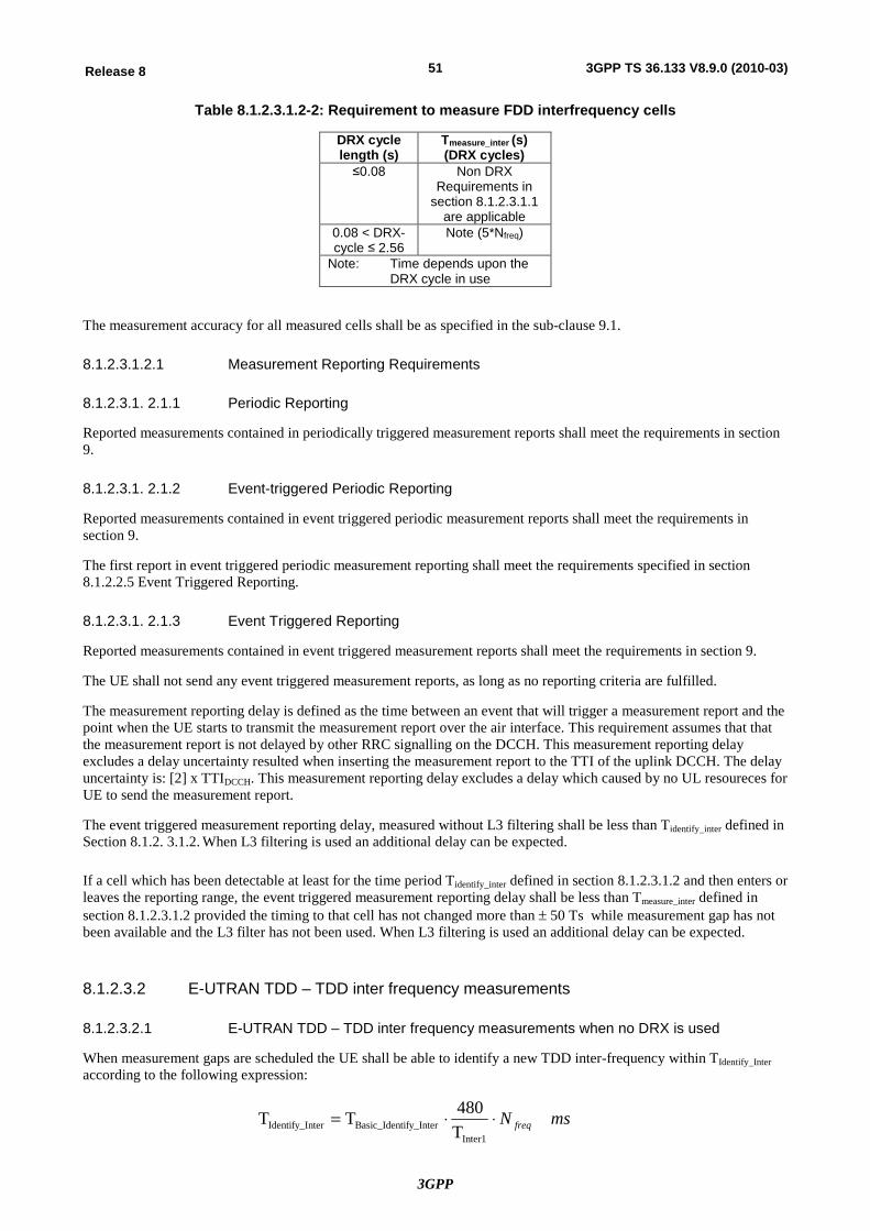
3GPP
51Release 8 3GPP TS 36.133 V8.9.0 (2010-03)
Table 8.1.2.3.1.2-2: Requirement to measure FDD interfrequency cells
DRX cycle length (s)
Tmeasure_inter (s) (DRX cycles)
≤0.08 Non DRX Requirements in
section 8.1.2.3.1.1 are applicable
0.08 < DRX-cycle ≤ 2.56
Note (5*Nfreq)
Note: Time depends upon the DRX cycle in use
The measurement accuracy for all measured cells shall be as specified in the sub-clause 9.1.
8.1.2.3.1.2.1 Measurement Reporting Requirements
8.1.2.3.1. 2.1.1 Periodic Reporting
Reported measurements contained in periodically triggered measurement reports shall meet the requirements in section 9.
8.1.2.3.1. 2.1.2 Event-triggered Periodic Reporting
Reported measurements contained in event triggered periodic measurement reports shall meet the requirements in section 9.
The first report in event triggered periodic measurement reporting shall meet the requirements specified in section 8.1.2.2.5 Event Triggered Reporting.
8.1.2.3.1. 2.1.3 Event Triggered Reporting
Reported measurements contained in event triggered measurement reports shall meet the requirements in section 9.
The UE shall not send any event triggered measurement reports, as long as no reporting criteria are fulfilled.
The measurement reporting delay is defined as the time between an event that will trigger a measurement report and the point when the UE starts to transmit the measurement report over the air interface. This requirement assumes that that the measurement report is not delayed by other RRC signalling on the DCCH. This measurement reporting delay excludes a delay uncertainty resulted when inserting the measurement report to the TTI of the uplink DCCH. The delay uncertainty is: [2] x TTIDCCH. This measurement reporting delay excludes a delay which caused by no UL resoureces for UE to send the measurement report.
The event triggered measurement reporting delay, measured without L3 filtering shall be less than Tidentify_inter defined in Section 8.1.2. 3.1.2. When L3 filtering is used an additional delay can be expected.
If a cell which has been detectable at least for the time period Tidentify_inter defined in section 8.1.2.3.1.2 and then enters or leaves the reporting range, the event triggered measurement reporting delay shall be less than Tmeasure_inter defined in section 8.1.2.3.1.2 provided the timing to that cell has not changed more than ± 50 Ts while measurement gap has not been available and the L3 filter has not been used. When L3 filtering is used an additional delay can be expected.
8.1.2.3.2 E-UTRAN TDD – TDD inter frequency measurements
8.1.2.3.2.1 E-UTRAN TDD – TDD inter frequency measurements when no DRX is used
When measurement gaps are scheduled the UE shall be able to identify a new TDD inter-frequency within TIdentify_Inter according to the following expression:
msN freq××=Inter1
tify_InterBasic_IdennterIdentify_I T480TT
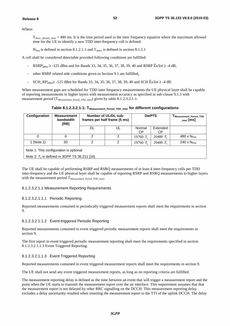
3GPP
52Release 8 3GPP TS 36.133 V8.9.0 (2010-03)
Where:
TBasic_Identify_Inter = 480 ms. It is the time period used in the inter frequency equation where the maximum allowed time for the UE to identify a new TDD inter-frequency cell is defined.
Nfreq is defined in section 8.1.2.1.1 and Tinter1 is defined in section 8.1.2.1
A cell shall be considered detectable provided following conditions are fulfilled:
- RSRP|dBm ³ -125 dBm and for Bands 33, 34, 35, 36, 37, 38, 39, 40 and RSRP Ês/Iot ³ -4 dB,
- other RSRP related side conditions given in Section 9.1 are fulfilled,
- SCH_RP|dBm³ -125 dBm for Bands 33, 34, 35, 36, 37, 38, 39, 40 and SCH Ês/Iot ³ -4 dB.
When measurement gaps are scheduled for TDD inter frequency measurements the UE physical layer shall be capable of reporting measurements to higher layers with measurement accuracy as specified in sub-clause 9.1.3 with measurement period (TMeasurement_Period_TDD_Inter) given by table 8.1.2.3.2.1-1:
Table 8.1.2.3.2.1-1: TMeasurement_Period_TDD_Inter for different configurations
Configuration Measurement bandwidth
[RB]
Number of UL/DL sub-frames per half frame (5 ms)
DwPTS
TMeasurement_Period_TDD_Inter [ms]
DL UL Normal
CP Extended
CP
0 6 2 2 s19760 T× s20480 T× 480 x Nfreq
1 (Note 1) 50 2 2 s19760 T× s20480 T× 240 x Nfreq
Note 1: This configuration is optional
Note 2: Ts is defined in 3GPP TS 36.211 [16]
The UE shall be capable of performing RSRP and RSRQ measurements of at least 4 inter-frequency cells per TDD inter-frequency and the UE physical layer shall be capable of reporting RSRP and RSRQ measurements to higher layers with the measurement period TMeasurement_Period_TDD_Inter.
8.1.2.3.2.1.1 Measurement Reporting Requirements
8.1.2.3.2.1.1.1 Periodic Reporting
Reported measurements contained in periodically triggered measurement reports shall meet the requirements in section 9.
8.1.2.3.2.1.1.2 Event-triggered Periodic Reporting
Reported measurements contained in event triggered periodic measurement reports shall meet the requirements in section 9.
The first report in event triggered periodic measurement reporting shall meet the requirements specified in section 8.1.2.3.2.1.1.3 Event Triggered Reporting.
8.1.2.3.2.1.1.3 Event Triggered Reporting
Reported measurements contained in event triggered measurement reports shall meet the requirements in section 9.
The UE shall not send any event triggered measurement reports, as long as no reporting criteria are fulfilled.
The measurement reporting delay is defined as the time between an event that will trigger a measurement report and the point when the UE starts to transmit the measurement report over the air interface. This requirement assumes that that the measurement report is not delayed by other RRC signalling on the DCCH. This measurement reporting delay excludes a delay uncertainty resulted when inserting the measurement report to the TTI of the uplink DCCH. The delay
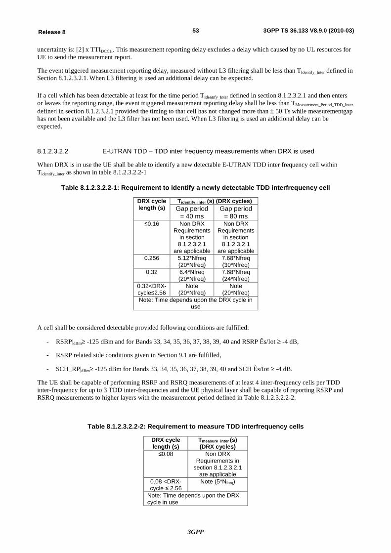
3GPP
53Release 8 3GPP TS 36.133 V8.9.0 (2010-03)
uncertainty is: [2] x TTIDCCH. This measurement reporting delay excludes a delay which caused by no UL resources for UE to send the measurement report.
The event triggered measurement reporting delay, measured without L3 filtering shall be less than TIdentify_Inter defined in Section 8.1.2.3.2.1. When L3 filtering is used an additional delay can be expected.
If a cell which has been detectable at least for the time period TIdentify_Inter defined in section 8.1.2.3.2.1 and then enters or leaves the reporting range, the event triggered measurement reporting delay shall be less than TMeasurement_Period_TDD_Inter defined in section 8.1.2.3.2.1 provided the timing to that cell has not changed more than ± 50 Ts while measurementgap has not been available and the L3 filter has not been used. When L3 filtering is used an additional delay can be expected.
8.1.2.3.2.2 E-UTRAN TDD – TDD inter frequency measurements when DRX is used
When DRX is in use the UE shall be able to identify a new detectable E-UTRAN TDD inter frequency cell within Tidentify_inter as shown in table 8.1.2.3.2.2-1
Table 8.1.2.3.2.2-1: Requirement to identify a newly detectable TDD interfrequency cell
DRX cycle length (s)
Tidentify_inter (s) (DRX cycles) Gap period
= 40 ms Gap period
= 80 ms ≤0.16 Non DRX
Requirements in section 8.1.2.3.2.1
are applicable
Non DRX Requirements
in section 8.1.2.3.2.1
are applicable 0.256 5.12*Nfreq
(20*Nfreq) 7.68*Nfreq (30*Nfreq)
0.32 6.4*Nfreq (20*Nfreq)
7.68*Nfreq (24*Nfreq)
0.32<DRX-cycle≤2.56
Note (20*Nfreq)
Note (20*Nfreq)
Note: Time depends upon the DRX cycle in use
A cell shall be considered detectable provided following conditions are fulfilled:
- RSRP|dBm³ -125 dBm and for Bands 33, 34, 35, 36, 37, 38, 39, 40 and RSRP Ês/Iot ³ -4 dB,
- RSRP related side conditions given in Section 9.1 are fulfilled,
- SCH_RP|dBm³ -125 dBm for Bands 33, 34, 35, 36, 37, 38, 39, 40 and SCH Ês/Iot ³ -4 dB.
The UE shall be capable of performing RSRP and RSRQ measurements of at least 4 inter-frequency cells per TDD inter-frequency for up to 3 TDD inter-frequencies and the UE physical layer shall be capable of reporting RSRP and RSRQ measurements to higher layers with the measurement period defined in Table 8.1.2.3.2.2-2.
Table 8.1.2.3.2.2-2: Requirement to measure TDD interfrequency cells
DRX cycle length (s)
Tmeasure_inter (s) (DRX cycles)
≤0.08 Non DRX Requirements in
section 8.1.2.3.2.1 are applicable
0.08 <DRX-cycle ≤ 2.56
Note (5*Nfreq)
Note: Time depends upon the DRX cycle in use
3GPP
54Release 8 3GPP TS 36.133 V8.9.0 (2010-03)
The measurement accuracy for all measured cells shall be as specified in the sub-clause 9.1.
8.1.2.3.2.2.1 Measurement Reporting Requirements
8.1.2.3.2.2.1.1 Periodic Reporting
Reported measurements contained in periodically triggered measurement reports shall meet the requirements in section 9.
8.1.2.3.2.2.1.2 Event-triggered Periodic Reporting
Reported measurements contained in event triggered periodic measurement reports shall meet the requirements in section 9.
The first report in event triggered periodic measurement reporting shall meet the requirements specified in section 8.1.2.3.2.2.1.3 Event Triggered Reporting.
8.1.2.3.2.2.1.3 Event Triggered Reporting
Reported measurements contained in event triggered measurement reports shall meet the requirements in section 9.
The UE shall not send any event triggered measurement reports, as long as no reporting criteria are fulfilled.
The measurement reporting delay is defined as the time between an event that will trigger a measurement report and the point when the UE starts to transmit the measurement report over the air interface. This requirement assumes that that the measurement report is not delayed by other RRC signalling on the DCCH. This measurement reporting delay excludes a delay uncertainty resulted when inserting the measurement report to the TTI of the uplink DCCH. The delay uncertainty is: [2] x TTIDCCH. This measurement reporting delay excludes a delay which caused by no UL resources for UE to send the measurement report.
The event triggered measurement reporting delay, measured without L3 filtering shall be less than TIdentify_Inter defined in Section 8.1.2.3.2.2. When L3 filtering is used an additional delay can be expected.
If a cell which has been detectable at least for the time period TIdentify_Inter in section 8.1.2.3.2.2 and then enters or leaves the reporting range, the event triggered measurement reporting delay shall be less than Tmeasure_inter in section 8.1.2.3.2.2 provided the timing to that cell has not changed more than ± 50 Ts while measurement gap has not been available and the L3 filter has not been used. When L3 filtering is used an additional delay can be expected.
8.1.2.3.3 E-UTRAN TDD – FDD inter frequency measurements
8.1.2.3.3.1 E-UTRAN TDD – FDD inter frequency measurements when no DRX is used
The requirements in this section shall apply to UE supporting FDD and TDD.
The requirements in section 8.1.2.3.1.1 also apply for this section.
8.1.2.3.3.2 E-UTRAN TDD – FDD inter frequency measurements when DRX is used
The requirements in this section shall apply to UE supporting FDD and TDD.
The requirements in section 8.1.2.3.1.2 also apply for this section.
8.1.2.3.3.2 (Void)
8.1.2.3.4 E-UTRAN FDD – TDD inter frequency measurements
8.1.2.3.4.1 E-UTRAN FDD – TDD inter frequency measurements when no DRX is used
The requirements in this section shall apply to UE supporting FDD and TDD.
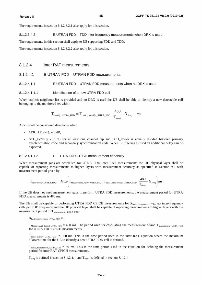
3GPP
55Release 8 3GPP TS 36.133 V8.9.0 (2010-03)
The requirements in section 8.1.2.3.2.1 also apply for this section.
8.1.2.3.4.2 E-UTRAN FDD – TDD inter frequency measurements when DRX is used
The requirements in this section shall apply to UE supporting FDD and TDD.
The requirements in section 8.1.2.3.2.2 also apply for this section.
8.1.2.4 Inter RAT measurements
8.1.2.4.1 E-UTRAN FDD – UTRAN FDD measurements
8.1.2.4.1.1 E-UTRAN FDD – UTRAN FDD measurements when no DRX is used
8.1.2.4.1.1.1 Identification of a new UTRA FDD cell
When explicit neighbour list is provided and no DRX is used the UE shall be able to identify a new detectable cell belonging to the monitored set within
msNFreq××=inter1
UTRA_FDD_identify_basic UTRA_FDDidentify, T480TT
A cell shall be considered detectable when
- CPICH Ec/Io > -20 dB,
- SCH_Ec/Io > -17 dB for at least one channel tap and SCH_Ec/Ior is equally divided between primary synchronisation code and secondary synchronisation code. When L3 filtering is used an additional delay can be expected.
8.1.2.4.1.1.2 UE UTRA FDD CPICH measurement capability
When measurement gaps are scheduled for UTRA FDD inter RAT measurements the UE physical layer shall be capable of reporting measurements to higher layers with measurement accuracy as specified in Section 9.2 with measurement period given by
msNMax Freqþýü
îíì
××=inter1
UTRA_FDD_tmeasuremen_basic UTRA_FDDt_PeriodMeasuremen_UTRA_FDDtmeasuremen T480T, TT
If the UE does not need measurement gaps to perform UTRA FDD measurements, the measurement period for UTRA FDD measurements is 480 ms.
The UE shall be capable of performing UTRA FDD CPICH measurements for Xbasic measurementUTRA_FDD inter-frequency cells per FDD frequency and the UE physical layer shall be capable of reporting measurements to higher layers with the measurement period of TMeasurement_ UTRA_FDD.
Xbasic measurement UTRA_FDD = 6
TMeasurement_Period UTRA_FDD = 480 ms. The period used for calculating the measurement period Tmeasurement_UTRA_FDD for UTRA FDD CPICH measurements.
Tbasic_identify_UTRA_FDD = 300 ms. This is the time period used in the inter RAT equation where the maximum allowed time for the UE to identify a new UTRA FDD cell is defined.
Tbasic_measurement_UTRA_FDD = 50 ms. This is the time period used in the equation for defining the measurement period for inter RAT CPICH measurements.
Nfreq is defined in section 8.1.2.1.1 and Tinter1 is defined in section 8.1.2.1
3GPP
56Release 8 3GPP TS 36.133 V8.9.0 (2010-03)
8.1.2.4.1.1.3 Periodic Reporting
Reported measurements in periodically triggered measurement reports shall meet the requirements in section 9.
8.1.2.4.1.1.4 Event Triggered Reporting
Reported measurements in event triggered measurement reports shall meet the requirements in section 9.
The UE shall not send any event triggered measurement reports, as long as the reporting criteria is not fulfilled.
The measurement reporting delay is defined as the time between any event that will trigger a measurement report until the UE starts to transmit the measurement report over the Uu interface. This requirement assumes that the measurement report is not delayed by other RRC signalling on the DCCH. This measurement reporting delay excludes a delay uncertainty resulted when inserting the measurement report to the TTI of the uplink DCCH. The delay uncertainty is twice the TTI of the uplink DCCH. This measurement reporting delay excludes a delay which caused by no UL resources for UE to send the measurement report.
The event triggered measurement reporting delay, measured without L3 filtering shall be less than Tidentify, UTRA_FDD defined in Section 8.1.2.4.1.1.1. When L3 filtering is used an additional delay can be expected.
If a cell which has been detectable at least for the time period Tidentify, UTRA_FDD defined in section 8.1.2.4.1.1.1 and then enters or leaves the reporting range, the event triggered measurement reporting delay shall be less than Tmeasurement_UTRA_FDD defined in section 8.1.2.4.1.1.2 provided the timing to that cell has not changed more than ± 32 chips while measurement gap has not been available and the L3 filter has not been used. When L3 filtering is used an additional delay can be expected.
8.1.2.4.1.1.5 Event-triggered Periodic Reporting
Reported measurements contained in event triggered periodic measurement reports shall meet the requirements in section 9.
The first report in event triggered periodic measurement reporting shall meet the requirements specified in section 8.1.2.4.1.1.4 Event Triggered Reporting.
8.1.2.4.1.2 E-UTRAN FDD – UTRAN FDD measurements when DRX is used
When explicit neighbour list is provided and DRX is used the UE shall be able to identify a new detectable cell belonging to the neighbour cell list within Tidentify,UTRA_FDD as shown in table 8.1.2.4.1.2-1
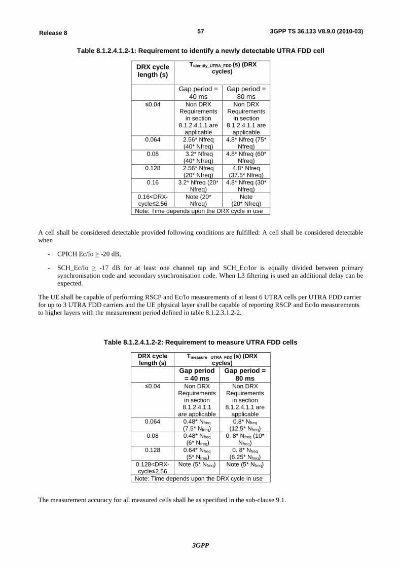
3GPP
57Release 8 3GPP TS 36.133 V8.9.0 (2010-03)
Table 8.1.2.4.1.2-1: Requirement to identify a newly detectable UTRA FDD cell
DRX cycle length (s)
Tidentify_UTRA_FDD (s) (DRX cycles)
Gap period = 40 ms
Gap period = 80 ms
≤0.04 Non DRX Requirements
in section 8.1.2.4.1.1 are
applicable
Non DRX Requirements
in section 8.1.2.4.1.1 are
applicable 0.064 2.56* Nfreq
(40* Nfreq) 4.8* Nfreq (75*
Nfreq) 0.08 3.2* Nfreq
(40* Nfreq) 4.8* Nfreq (60*
Nfreq) 0.128 2.56* Nfreq
(20* Nfreq) 4.8* Nfreq
(37.5* Nfreq) 0.16 3.2* Nfreq (20*
Nfreq) 4.8* Nfreq (30*
Nfreq) 0.16<DRX-cycle≤2.56
Note (20* Nfreq)
Note (20* Nfreq)
Note: Time depends upon the DRX cycle in use
A cell shall be considered detectable provided following conditions are fulfilled: A cell shall be considered detectable when
- CPICH Ec/Io > -20 dB,
- SCH_Ec/Io > -17 dB for at least one channel tap and SCH_Ec/Ior is equally divided between primary synchronisation code and secondary synchronisation code. When L3 filtering is used an additional delay can be expected.
The UE shall be capable of performing RSCP and Ec/Io measurements of at least 6 UTRA cells per UTRA FDD carrier for up to 3 UTRA FDD carriers and the UE physical layer shall be capable of reporting RSCP and Ec/Io measurements to higher layers with the measurement period defined in table 8.1.2.3.1.2-2.
Table 8.1.2.4.1.2-2: Requirement to measure UTRA FDD cells
DRX cycle length (s)
Tmeasure_ UTRA_FDD (s) (DRX cycles)
Gap period = 40 ms
Gap period = 80 ms
≤0.04 Non DRX Requirements
in section 8.1.2.4.1.1
are applicable
Non DRX Requirements
in section 8.1.2.4.1.1 are
applicable 0.064 0.48* Nfreq
(7.5* Nfreq) 0.8* Nfreq
(12.5* Nfreq) 0.08 0.48* Nfreq
(6* Nfreq) 0. 8* Nfreq (10*
Nfreq) 0.128 0.64* Nfreq
(5* Nfreq) 0. 8* Nfreq
(6.25* Nfreq) 0.128<DRX-cycle≤2.56
Note (5* Nfreq) Note (5* Nfreq)
Note: Time depends upon the DRX cycle in use
The measurement accuracy for all measured cells shall be as specified in the sub-clause 9.1.
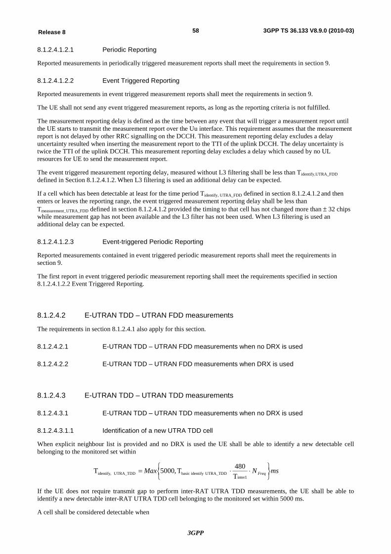
3GPP
58Release 8 3GPP TS 36.133 V8.9.0 (2010-03)
8.1.2.4.1.2.1 Periodic Reporting
Reported measurements in periodically triggered measurement reports shall meet the requirements in section 9.
8.1.2.4.1.2.2 Event Triggered Reporting
Reported measurements in event triggered measurement reports shall meet the requirements in section 9.
The UE shall not send any event triggered measurement reports, as long as the reporting criteria is not fulfilled.
The measurement reporting delay is defined as the time between any event that will trigger a measurement report until the UE starts to transmit the measurement report over the Uu interface. This requirement assumes that the measurement report is not delayed by other RRC signalling on the DCCH. This measurement reporting delay excludes a delay uncertainty resulted when inserting the measurement report to the TTI of the uplink DCCH. The delay uncertainty is twice the TTI of the uplink DCCH. This measurement reporting delay excludes a delay which caused by no UL resources for UE to send the measurement report.
The event triggered measurement reporting delay, measured without L3 filtering shall be less than Tidentify,UTRA_FDD defined in Section 8.1.2.4.1.2. When L3 filtering is used an additional delay can be expected.
If a cell which has been detectable at least for the time period Tidentify, UTRA_FDD defined in section 8.1.2.4.1.2 and then enters or leaves the reporting range, the event triggered measurement reporting delay shall be less than Tmeasurement_UTRA_FDD defined in section 8.1.2.4.1.2 provided the timing to that cell has not changed more than ± 32 chips while measurement gap has not been available and the L3 filter has not been used. When L3 filtering is used an additional delay can be expected.
8.1.2.4.1.2.3 Event-triggered Periodic Reporting
Reported measurements contained in event triggered periodic measurement reports shall meet the requirements in section 9.
The first report in event triggered periodic measurement reporting shall meet the requirements specified in section 8.1.2.4.1.2.2 Event Triggered Reporting.
8.1.2.4.2 E-UTRAN TDD – UTRAN FDD measurements
The requirements in section 8.1.2.4.1 also apply for this section.
8.1.2.4.2.1 E-UTRAN TDD – UTRAN FDD measurements when no DRX is used
8.1.2.4.2.2 E-UTRAN TDD – UTRAN FDD measurements when DRX is used
8.1.2.4.3 E-UTRAN TDD – UTRAN TDD measurements
8.1.2.4.3.1 E-UTRAN TDD – UTRAN TDD measurements when no DRX is used
8.1.2.4.3.1.1 Identification of a new UTRA TDD cell
When explicit neighbour list is provided and no DRX is used the UE shall be able to identify a new detectable cell belonging to the monitored set within
msNMax Freq þýü
îíì ××=
inter1UTRA_TDDidentifybasic UTRA_TDDidentify, T
480T,5000T
If the UE does not require transmit gap to perform inter-RAT UTRA TDD measurements, the UE shall be able to identify a new detectable inter-RAT UTRA TDD cell belonging to the monitored set within 5000 ms.
A cell shall be considered detectable when
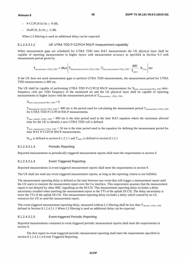
3GPP
59Release 8 3GPP TS 36.133 V8.9.0 (2010-03)
- P-CCPCH Ec/Io > -8 dB,
- DwPCH_Ec/Io > -5 dB.
When L3 filtering is used an additional delay can be expected.
8.1.2.4.3.1.2 UE UTRA TDD P-CCPCH RSCP measurement capability
When measurement gaps are scheduled for UTRA TDD inter RAT measurements the UE physical layer shall be capable of reporting measurements to higher layers with measurement accuracy as specified in Section 9.3 with measurement period given by
msNMax Freqþýü
îíì
××=inter1
UTRA_TDDtmeasuremenbasic UTRA_TDDt_PeriodMeasuremen UTRA_TDDtmeasuremen T480T, TT
If the UE does not need measurement gaps to perform UTRA TDD measurements, the measurement period for UTRA TDD measurements is 480 ms.
The UE shall be capable of performing UTRA TDD P-CCPCH RSCP measurements for Xbasic measurementUTRA_TDD inter-frequency cells per TDD frequency of the monitored set and the UE physical layer shall be capable of reporting measurements to higher layers with the measurement period of TMeasurement_ UTRA_TDD.
Xbasic measurementUTRA_TDD = 6
TMeasurement_Period UTRA_TDD = 480 ms is the period used for calculating the measurement period Tmeasurement_UTRA_TDD for UTRA TDD P-CCPCH RSCP measurements.
Tbasic_identify_UTRA_TDD = 800 ms is the time period used in the inter RAT equation where the maximum allowed time for the UE to identify a new UTRA TDD cell is defined.
Tbasic_measurement_UTRA_TDD = 50 ms is the time period used in the equation for defining the measurement period for inter RAT P-CCPCH RSCP measurements.
Nfreq is defined in section 8.1.2.1.1 and Tinter1 is defined in section 8.1.2.1
8.1.2.4.3.1.3 Periodic Reporting
Reported measurements in periodically triggered measurement reports shall meet the requirements in section 9.
8.1.2.4.3.1.4 Event Triggered Reporting
Reported measurements in event triggered measurement reports shall meet the requirements in section 9.
The UE shall not send any event triggered measurement reports, as long as the reporting criteria is not fulfilled.
The measurement reporting delay is defined as the time between any event that will trigger a measurement report until the UE starts to transmit the measurement report over the Uu interface. This requirement assumes that the measurement report is not delayed by other RRC signalling on the DCCH. This measurement reporting delay excludes a delay uncertainty resulted when inserting the measurement report to the TTI of the uplink DCCH. The delay uncertainty is twice the TTI of the uplink DCCH. This measurement reporting delay excludes a delay which caused by no UL resources for UE to send the measurement report.
The event triggered measurement reporting delay, measured without L3 filtering shall be less than Tidentify, UTRA_TDD defined in Section 8.1.2.4.3.1.1 When L3 filtering is used an additional delay can be expected.
8.1.2.4.3.1.5 Event-triggered Periodic Reporting
Reported measurements contained in event triggered periodic measurement reports shall meet the requirements in section 9.
The first report in event triggered periodic measurement reporting shall meet the requirements specified in section 8.1.2.4.3.1.4 Event Triggered Reporting.
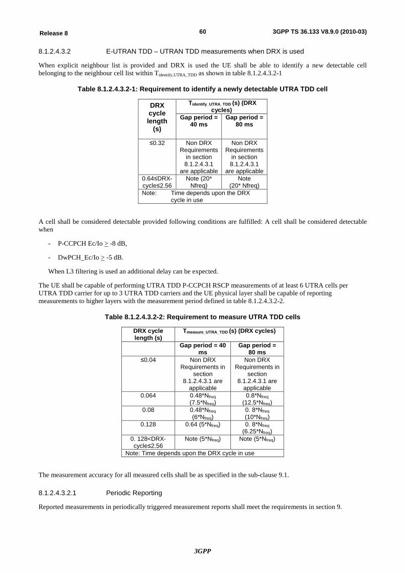
3GPP
60Release 8 3GPP TS 36.133 V8.9.0 (2010-03)
8.1.2.4.3.2 E-UTRAN TDD – UTRAN TDD measurements when DRX is used
When explicit neighbour list is provided and DRX is used the UE shall be able to identify a new detectable cell belonging to the neighbour cell list within Tidentify,UTRA_TDD as shown in table 8.1.2.4.3.2-1
Table 8.1.2.4.3.2-1: Requirement to identify a newly detectable UTRA TDD cell
DRX cycle length
(s)
Tidentify_UTRA_TDD (s) (DRX cycles)
Gap period = 40 ms
Gap period = 80 ms
≤0.32 Non DRX Requirements
in section 8.1.2.4.3.1
are applicable
Non DRX Requirements
in section 8.1.2.4.3.1
are applicable 0.64≤DRX-cycle≤2.56
Note (20* Nfreq)
Note (20* Nfreq)
Note: Time depends upon the DRX cycle in use
A cell shall be considered detectable provided following conditions are fulfilled: A cell shall be considered detectable when
- P-CCPCH Ec/Io > -8 dB,
- DwPCH_Ec/Io > -5 dB.
When L3 filtering is used an additional delay can be expected.
The UE shall be capable of performing UTRA TDD P-CCPCH RSCP measurements of at least 6 UTRA cells per UTRA TDD carrier for up to 3 UTRA TDD carriers and the UE physical layer shall be capable of reporting measurements to higher layers with the measurement period defined in table 8.1.2.4.3.2-2.
Table 8.1.2.4.3.2-2: Requirement to measure UTRA TDD cells
DRX cycle length (s)
Tmeasure_UTRA_TDD (s) (DRX cycles)
Gap period = 40 ms
Gap period = 80 ms
≤0.04 Non DRX Requirements in
section 8.1.2.4.3.1 are
applicable
Non DRX Requirements in
section 8.1.2.4.3.1 are
applicable 0.064 0.48*Nfreq
(7.5*Nfreq) 0.8*Nfreq
(12.5*Nfreq) 0.08 0.48*Nfreq
(6*Nfreq) 0. 8*Nfreq (10*Nfreq)
0.128 0.64 (5*Nfreq) 0. 8*Nfreq (6.25*Nfreq)
0. 128<DRX-cycle≤2.56
Note (5*Nfreq) Note (5*Nfreq)
Note: Time depends upon the DRX cycle in use
The measurement accuracy for all measured cells shall be as specified in the sub-clause 9.1.
8.1.2.4.3.2.1 Periodic Reporting
Reported measurements in periodically triggered measurement reports shall meet the requirements in section 9.
3GPP
61Release 8 3GPP TS 36.133 V8.9.0 (2010-03)
8.1.2.4.3.2.2 Event Triggered Reporting
Reported measurements in event triggered measurement reports shall meet the requirements in section 9.
The UE shall not send any event triggered measurement reports, as long as the reporting criteria is not fulfilled.
The measurement reporting delay is defined as the time between any event that will trigger a measurement report until the UE starts to transmit the measurement report over the Uu interface. This requirement assumes that the measurement report is not delayed by other RRC signalling on the DCCH. This measurement reporting delay excludes a delay uncertainty resulted when inserting the measurement report to the TTI of the uplink DCCH. The delay uncertainty is twice the TTI of the uplink DCCH. This measurement reporting delay excludes a delay which caused by no UL resources for UE to send the measurement report.
The event triggered measurement reporting delay, measured without L3 filtering shall be less than Tidentify, UTRA_TDD defined in Section 8.1.2.4.3.2 When L3 filtering is used an additional delay can be expected.
8.1.2.4.3.2.3 Event-triggered Periodic Reporting
Reported measurements contained in event triggered periodic measurement reports shall meet the requirements in section 9.
The first report in event triggered periodic measurement reporting shall meet the requirements specified in section 8.1.2.4.3.2.2 Event Triggered Reporting.
8.1.2.4.4 E-UTRAN FDD – UTRAN TDD measurements
The requirements in section 8.1.2.4.3 also apply for this section.
8.1.2.4.5 E-UTRAN FDD – GSM measurements
8.1.2.4.5.1 E-UTRAN FDD – GSM measurements when no DRX is used
The requirements in this section apply only to UE supporting E-UTRAN FDD and GSM.
Measurements on GSM cells can be requested with BSIC verified.
In RRC_CONNECTED state when a supported measurement gap pattern sequence according to Table 8.1.2.1-1 is configured by E-UTRAN the UE shall continuously measure GSM cells, search for new GSM cells given in the monitored set and re-confirm the BSIC for already detected cells.
8.1.2.4.5.1.1 GSM carrier RSSI
This measurement shall be based on measurement gaps allocated for GSM carrier RSSI measurement as described in section 8.1.2.1. A UE supporting GSM measurements shall measure minimum number of 10 GSM carrier RSSI measurement samples (NGSM carrier RSSI) per measurement gap. In RRC_CONNECTED state the measurement period, TMeasurement Period, GSM, for the GSM carrier RSSI measurement is Nfreq*480 ms. The parameter Nfreq is defined in section 8.1.2.1.1.
The UE shall meet the measurement accuracy requirements stated for RXLEV in [8], when the given measurement time allows the UE to take at least 3 GSM carrier RSSI samples per GSM carrier in the monitored set during the measurement period.
In case the UE is not able to acquire the required number of samples per GSM carrier during one measurement period, the UE shall measure as many GSM carriers as possible during that measurement period using at least 3 samples per GSM carrier. The GSM carriers that were not measured during that measurement period shall be measured in the following measurement periods.
3GPP
62Release 8 3GPP TS 36.133 V8.9.0 (2010-03)
8.1.2.4.5.1.2 BSIC verification
Measurements on a GSM cell can be requested with BSIC verified. The UE shall be able to report the GSM cells with BSIC verified for those cells where the verification of BSIC has been successful.
The procedure for BSIC verification on a GSM cell can be divided into the following two tasks:
- Initial BSIC identification: Includes searching for the BSIC and decoding the BSIC for the first time when there is no knowledge about the relative timing between the E-UTRAN FDD and GSM cells. The UE shall trigger the initial BSIC identification within the available measurement gap pattern sequence. The requirements for BSIC re-confirmation can be found in section 8.1.2.4.5.1.2.1.
- BSIC re-confirmation: Tracking and decoding the BSIC of a GSM cell after initial BSIC identification is performed. The UE shall trigger the BSIC re-confirmation within the available measurement gap pattern. The requirements for BSIC re-confirmation can be found in section 8.1.2.4.5.1.2.2.
If the network requests measurements on a GSM cell, the UE shall behave as follows:
- The UE shall perform GSM carrier RSSI measurements according to section 8.1.2.4.5.1 when a measurement gap pattern sequence is activated.
- The UE shall perform measurement reporting as defined in [2].
- The UE shall perform BSIC identification if BSIC verified measurements are activated by RRC. The UE shall use the most recently available GSM carrier RSSI measurement results for arranging GSM cells in signal strength order for performing BSIC identification.
- The UE shall perform BSIC re-confirmation on all the GSM cells that have been successfully identified.
- The UE shall perform all configured event evaluation for event-triggered reporting after the BSIC has been verified for a GSM cell. The UE shall use the most recently available GSM carrier RSSI measurement results in event evaluation and event-triggered reporting.
- Event-triggered and periodic reports shall be triggered according to [2].
The BSIC of a GSM cell is considered to be “verified” if the UE has decoded the SCH of the BCCH carrier and identified the BSIC at least one time (initial BSIC identification). Once a GSM cell has been identified the BSIC shall be re-confirmed at least once every 8*Tre-confirm,GSM seconds. Otherwise the BSIC of the GSM cell is considered as "non-verified". If a measurement gap pattern sequence is deactivated by the network after BSIC has been identified or verified, the UE shall consider the BSIC as non-verified.
Tidentify,GSM indicates the maximum time allowed for the UE to decode the unknown BSIC of the GSM cell in one GSM BCCH carrier in the initial BSIC identification procedure.
Tre-confirm,GSM indicates the maximum time allowed for the re-confirmation of the BSIC of one GSM cell in the BSIC re-confirmation procedure.
The UE shall be able to decode a BSIC within a measurement gap when the time difference between the middle of the received GSM synchronisation burst at the UE and the middle of the effective measurement gap is within the limits specified in table 8.1.2.4.5.1.2-1.
Table 8.1.2.4.5.1.2-1: The gap length and maximum time difference for BSIC verification
Gap length [ms]
Maximum time difference [ms]
6 ± 2350 µs
The UE shall be able to perform BSIC verification at levels down to the reference sensitivity level or reference interference levels as specified in [9].
3GPP
63Release 8 3GPP TS 36.133 V8.9.0 (2010-03)
8.1.2.4.5.1.2.1 Initial BSIC identification
This measurement shall be based on the measurement gaps used for Initial BSIC identification as described in section 8.1.2.4.5.1.2.
The UE shall continuously attempt to decode the BSIC of SCH on the BCCH carrier of the 8 strongest BCCH carriers of the GSM cells indicated in the Inter-RAT cell info list. The UE shall give priority for BSIC decoding attempts in decreasing signal strength order to BCCH carriers with unknown BSIC. The strongest BCCH carrier is defined as the BCCH carrier having the highest measured GSM carrier RSSI value.
If the BSIC of the GSM BCCH carrier has been successfully decoded the UE shall immediately continue BSIC identification with the next GSM BCCH carrier, in signal strength order, with unknown BSIC. The GSM cell for which the BSIC has been successfully identified shall be moved to the BSIC re-confirmation procedure.
If the UE has not successfully decoded the BSIC of the GSM BCCH carrier within Tidentify,GSM ms, the UE shall abort the BSIC identification attempts for that GSM BCCH carrier. The UE shall continue to try to perform BSIC identification of the next GSM BCCH carrier in signal strength order. The GSM BCCH carrier for which the BSIC identification failed shall not be re-considered for BSIC identification until BSIC identification attempts have been made for all the rest of the 8 strongest GSM BCCH carriers in the monitored set with unknown BSIC.
Tidentify,GSM values are given for a set of reference gap patterns in table 8.1.2.4.5.1.2.1-1. The requirements in the table represent the time required to guarantee at least two attempts to decode the BSIC for one GSM BCCH carrier.
Table 8.1.2.4.5.1.2.1-1
Number of
carriers other than GSM
Tidentify,gsm(ms) Treconfirm,gsm(ms)
40ms gap configuration
(ID 0)
80ms gap configuration
(ID 1)
40ms gap configuration
(ID 0)
80ms gap configuration
(ID 1) 0 2160 5280 1920 5040 1 [5280] [21760] [5040] [17280] 2 [5280] [31680] [5040] [29280]
3 [19440] No
requirement [13320] No
requirement
4 [31680] No
requirement [29280] No
requirement
5 [31680] No
requirement [29280] No
requirement
8.1.2.4.5.1.2.2 BSIC re-confirmation
The UE shall maintain the timing information of up to 8 identified GSM cells. Initial timing information is obtained from the initial BSIC identification. The timing information shall be updated every time the BSIC is decoded.
For each measurement gap used for GSM BSIC reconfirmation as described in section 8.1.2.4.5.1.2, the UE shall attempt to decode the BSIC falling within the measurement gap according to table 8.1.2.4.5.1.2.1-1. If more than one BSIC can be decoded within the same measurement gap, priority shall be given to the least recently decoded BSIC.
If the UE fails to decode the BSIC after two successive attempts or if the UE has not been able to re-confirm the BSIC for a GSM cell within Tre-confirm,GSM seconds, the UE shall abort the BSIC re-confirmation attempts for that GSM cell. The GSM cell shall be treated as a new GSM cell with unidentified BSIC and the GSM cell shall be moved to the initial BSIC identification procedure, see section 8.1.2.4.5.1.2.1.
8.1.2.4.5.1.3 Periodic Reporting
Reported measurements in periodically triggered measurement reports shall meet the requirements in section 9.
3GPP
64Release 8 3GPP TS 36.133 V8.9.0 (2010-03)
8.1.2.4.5.1.4 Event Triggered Reporting
Reported measurements in event triggered measurement reports shall meet the requirements in section 9.
The UE shall not send any event triggered measurement reports, as long as no reporting criteria are fulfilled.
The measurement reporting delay is defined as the time between an event that will trigger a measurement report and the point when the UE starts to transmit the measurement report over the air interface. This requirement assumes that that the measurement report is not delayed by other RRC signalling on the DCCH.
The event triggered reporting delay requirement is valid when the UE for each GSM carrier in the monitored set can take the required number of samples during the measurement period TMeasurement Period, GSM (see section 8.1.2.4.5.1).
The event triggered measurement reporting delay for a GSM cell with verified BSIC , measured without L3 filtering shall be less than 2*TMeasurement Period, GSM, where TMeasurement Period, GSM is defined in section 8.1.2.4.5.1. When L3 filtering is used an additional delay can be expected.
8.1.2.4.5.1.5 Event-triggered Periodic Reporting
Reported measurements contained in event triggered periodic measurement reports shall meet the requirements in section 9.
The first report in event triggered periodic measurement reporting shall meet the requirements specified in section 8.1.2.4.5.1.4 Event Triggered Reporting.
8.1.2.4.5.2 E-UTRAN FDD – GSM measurements when DRX is used
The requirements in this section apply only to UE supporting E-UTRAN FDD and GSM.
Measurements on GSM cells can be requested with BSIC verified.
In RRC_CONNECTED state when a supported measurement gap pattern sequence according to Table 8.1.2.1-1 is configured by E-UTRAN the UE shall continuously measure GSM cells, search for new GSM cells given in the monitored set and re-confirm the BSIC for already detected cells. During DRX periods the UE may use other periods of time outside the specified measurement gap patterns. The UE is not required to make measurements of GSM cells during DRX periods if a measurement gap pattern has not been configured.
8.1.2.4.5.2.1 GSM carrier RSSI
This measurement shall be based on measurement gaps allocated for GSM carrier RSSI measurement as described in section 8.1.2.1. A UE supporting GSM measurements shall measure minimum number of 10 GSM carrier RSSI measurement samples (NGSM carrier RSSI) per DRX cycle. In RRC_CONNECTED state the measurement period, TMeasurement Period, GSM, for the GSM carrier RSSI measurement is shown in table 8.1.2.4.5.2.1-1. The parameter Nfreq is defined in section 8.1.2.1.1.
Table 8.1.2.4.5.2.1-1: GSM measurement period for large DRX
DRX cycle length (s)
Tmeasure,GSM (s) (DRX cycles)
≤0.04 Non DRX Requirements are
applicable [0.08] 0.48 (6*Nfreq) [0.16] 0.8 (5*Nfreq) [0.32] 1.6 (5*Nfreq) [0.64] 3.2 (5*Nfreq) [1.28] 6.4 (5*Nfreq) [2.56] 12.8 (5*Nfreq)
3GPP
65Release 8 3GPP TS 36.133 V8.9.0 (2010-03)
The UE shall meet the measurement accuracy requirements stated for RXLEV in [8], when the given measurement time allows the UE to take at least 3 GSM carrier RSSI samples per GSM carrier in the monitored set during the measurement period.
In case the UE is not able to acquire the required number of samples per GSM carrier during one measurement period, the UE shall measure as many GSM carriers as possible during that measurement period using at least 3 samples per GSM carrier. The GSM carriers that were not measured during that measurement period shall be measured in the following measurement periods.
8.1.2.4.5.2.2 BSIC verification
Measurements on a GSM cell can be requested with BSIC verified. The UE shall be able to report the GSM cells with BSIC verified for those cells where the verification of BSIC has been successful.
The procedure for BSIC verification on a GSM cell can be divided into the following two tasks:
- Initial BSIC identification: Includes searching for the BSIC and decoding the BSIC for the first time when there is no knowledge about the relative timing between the E-UTRAN FDD and GSM cells.
- BSIC re-confirmation: Tracking and decoding the BSIC of a GSM cell after initial BSIC identification is performed. The UE shall trigger the BSIC re-confirmation within the available measurement gap pattern
If the network requests measurements on a GSM cell, the UE shall behave as follows:
- The UE shall perform GSM carrier RSSI measurements according to section 8.1.2.4.5.2.1 when a measurement gap pattern sequence is activated.
- The UE shall perform measurement reporting as defined in [2].
- The UE shall perform BSIC identification if BSIC verified measurements are activated by RRC. The UE shall use the most recently available GSM carrier RSSI measurement results for arranging GSM cells in signal strength order for performing BSIC identification.
- The UE shall perform BSIC re-confirmation on all the GSM cells that have been successfully identified.
- The UE shall perform all configured event evaluation for event-triggered reporting after the BSIC has been verified for a GSM cell. The UE shall use the most recently available GSM carrier RSSI measurement results in event evaluation and event-triggered reporting.
- Event-triggered and periodic reports shall be triggered according to [2].
The BSIC of a GSM cell is considered to be “verified” if the UE has decoded the SCH of the BCCH carrier and identified the BSIC at least one time (initial BSIC identification). Once a GSM cell has been identified the BSIC shall be re-confirmed at least once every 30 seconds. Otherwise the BSIC of the GSM cell is considered as "non-verified".
The UE shall be able to perform BSIC verification at levels down to the reference sensitivity level or reference interference levels as specified in [9].
8.1.2.4.5.2.2.1 Initial BSIC identification
This measurement shall be made on GSM cells that are requested with BSIC verified.
For DRX cycle length £ 40 ms, the initial GSM BSIC identification requirements corresponding to the non DRX requirements as specified in section 8.1.2.4.5.1.2.1 shall apply.
For DRX cycle length > 40 ms, the UE shall make at least one attempt every Nfreq*30s to decode the BSIC of SCH on the BCCH carrier of the 8 strongest BCCH carriers of the GSM cells indicated in the Inter-RAT cell info list. If the UE has not successfully decoded the BSIC of the GSM BCCH carrier within Nfreq*60 s, the UE shall abort the BSIC identification attempts for that GSM BCCH carrier. The UE shall give priority for BSIC decoding attempts in decreasing signal strength order to BCCH carriers with unknown BSIC. The strongest BCCH carrier is defined as the BCCH carrier having the highest measured GSM carrier RSSI value. The parameter Nfreq is defined in section 8.1.2.1.1.
If the BSIC of the GSM BCCH carrier has been successfully decoded the UE shall continue BSIC identification with the next GSM BCCH carrier, in signal strength order, with unknown BSIC. The GSM cell for which the BSIC has been successfully identified shall be moved to the BSIC re-confirmation procedure.
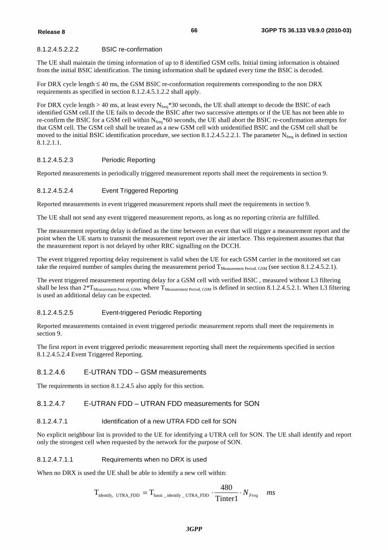
3GPP
66Release 8 3GPP TS 36.133 V8.9.0 (2010-03)
8.1.2.4.5.2.2.2 BSIC re-confirmation
The UE shall maintain the timing information of up to 8 identified GSM cells. Initial timing information is obtained from the initial BSIC identification. The timing information shall be updated every time the BSIC is decoded.
For DRX cycle length £ 40 ms, the GSM BSIC re-conformation requirements corresponding to the non DRX requirements as specified in section 8.1.2.4.5.1.2.2 shall apply.
For DRX cycle length > 40 ms, at least every Nfreq*30 seconds, the UE shall attempt to decode the BSIC of each identified GSM cell.If the UE fails to decode the BSIC after two successive attempts or if the UE has not been able to re-confirm the BSIC for a GSM cell within Nfreq*60 seconds, the UE shall abort the BSIC re-confirmation attempts for that GSM cell. The GSM cell shall be treated as a new GSM cell with unidentified BSIC and the GSM cell shall be moved to the initial BSIC identification procedure, see section 8.1.2.4.5.2.2.1. The parameter Nfreq is defined in section 8.1.2.1.1.
8.1.2.4.5.2.3 Periodic Reporting
Reported measurements in periodically triggered measurement reports shall meet the requirements in section 9.
8.1.2.4.5.2.4 Event Triggered Reporting
Reported measurements in event triggered measurement reports shall meet the requirements in section 9.
The UE shall not send any event triggered measurement reports, as long as no reporting criteria are fulfilled.
The measurement reporting delay is defined as the time between an event that will trigger a measurement report and the point when the UE starts to transmit the measurement report over the air interface. This requirement assumes that that the measurement report is not delayed by other RRC signalling on the DCCH.
The event triggered reporting delay requirement is valid when the UE for each GSM carrier in the monitored set can take the required number of samples during the measurement period TMeasurement Period, GSM (see section 8.1.2.4.5.2.1).
The event triggered measurement reporting delay for a GSM cell with verified BSIC , measured without L3 filtering shall be less than 2*TMeasurement Period, GSM, where TMeasurement Period, GSM is defined in section 8.1.2.4.5.2.1. When L3 filtering is used an additional delay can be expected.
8.1.2.4.5.2.5 Event-triggered Periodic Reporting
Reported measurements contained in event triggered periodic measurement reports shall meet the requirements in section 9.
The first report in event triggered periodic measurement reporting shall meet the requirements specified in section 8.1.2.4.5.2.4 Event Triggered Reporting.
8.1.2.4.6 E-UTRAN TDD – GSM measurements
The requirements in section 8.1.2.4.5 also apply for this section.
8.1.2.4.7 E-UTRAN FDD – UTRAN FDD measurements for SON
8.1.2.4.7.1 Identification of a new UTRA FDD cell for SON
No explicit neighbour list is provided to the UE for identifying a UTRA cell for SON. The UE shall identify and report only the strongest cell when requested by the network for the purpose of SON.
8.1.2.4.7.1.1 Requirements when no DRX is used
When no DRX is used the UE shall be able to identify a new cell within:
msN Freq××=Tinter1
480TT UTRA_FDD_identify_basic UTRA_FDDidentify,

3GPP
67Release 8 3GPP TS 36.133 V8.9.0 (2010-03)
Tbasic_identify_UTRA_FDD = 300 ms. This is the time period used in the above equation where the maximum allowed time for the UE to identify a new UTRA FDD cell is defined.
A cell shall be considered identifiable following conditions are fulfilled:
- CPICH Ec/Io > -20 dB,
- SCH_Ec/Io > -17 dB for at least one channel tap and SCH_Ec/Ior is equally divided between primary synchronisation code and secondary synchronisation code. When L3 filtering is used an additional delay can be expected.
If the UE is unable to identify the UTRA cell for SON within 8*Tidentify, UTRA_FDD ms, the UE may stop searching UTRA cells for SON.
8.1.2.4.7.1.2 Requirements when DRX is used
When DRX is used the UE shall be able to identify a new cell within Tidentify, UTRA_FDD as defined in table 8.1.2.4.7.1.2-1.
Table 8.1.2.4.7.1.2-1: Requirement to identify a new UTRA FDD cell for SON
DRX cycle length (s) Tidentify, UTRA_FDD (s) (DRX cycles)
Gap period = 40 ms Gap period = 80 ms
≤0.04 Non DRX Requirements in section 8.1.2.4.7.1.1
are applicable
Non DRX Requirements in section 8.1.2.4.7.1.1are
applicable 0.04<DRX cycle≤0.08 3.6* Nfreq (45* Nfreq) 7.6* Nfreq (95* Nfreq)
0.08<DRX cycle≤0.16 4.0* Nfreq (25* Nfreq) 8.0* Nfreq (50* Nfreq)
0.16<DRX cycle≤0.32 8* Nfreq (25* Nfreq) 8.96* Nfreq (28* Nfreq)
0.32<DRX cycle≤2.56 Note (25* Nfreq) Note (25* Nfreq)
Note: Time depends upon the DRX cycle in use
A cell shall be considered identifiable provided following conditions are fulfilled:
- CPICH Ec/Io > -20 dB,
- SCH_Ec/Io > -17 dB for at least one channel tap and SCH_Ec/Ior is equally divided between primary synchronisation code and secondary synchronisation code. When L3 filtering is used an additional delay can be expected.
If the UE is unable to identify the UTRA cell for SON within 8*Tidentify, UTRA_FDD seconds, the UE may stop searching UTRA cells for SON; Tidentify, UTRA_FDD is defined in table 8.1.2.4.7.1.2-1.
8.1.2.4.7.1.3 Reporting Delay
The UE shall not report the physical cell identity of an identifiable cell for SON as long as the reporting criteria are not fulfilled.
The reporting delay is defined as the time between the identification of the strongest cell for SON until the UE starts to transmit its physical cell identity over the Uu interface. This requirement assumes that the reporting of the physical cell identity is not delayed by other RRC signalling on the DCCH. This reporting delay excludes a delay uncertainty resulted when inserting the physical cell identity of the strongest cell for SON to the TTI of the uplink DCCH. The delay uncertainty is twice the TTI of the uplink DCCH. This reporting delay excludes any delay caused by unavailability of UL resources for UE sending the physical cell identity of the strongest cell for SON.
The reporting delay of the physical cell identity of the strongest cell for SON without L3 filtering shall be less than Tidentify, UTRA_FDD defined in section 8.1.2.4.7.1.1 and in section 8.1.2.4.7.1.2 for non DRX and DRX cases respectively. When L3 filtering is used an additional delay can be expected.
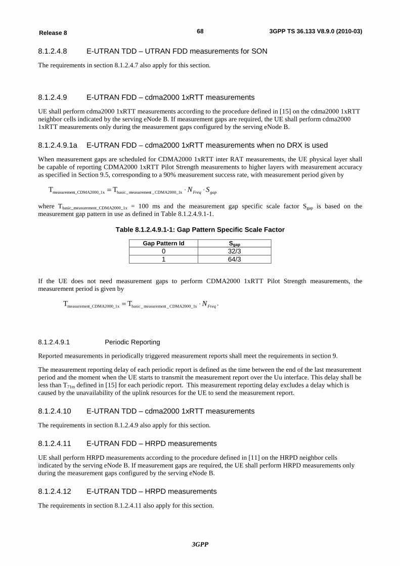
3GPP
68Release 8 3GPP TS 36.133 V8.9.0 (2010-03)
8.1.2.4.8 E-UTRAN TDD – UTRAN FDD measurements for SON
The requirements in section 8.1.2.4.7 also apply for this section.
8.1.2.4.9 E-UTRAN FDD – cdma2000 1xRTT measurements
UE shall perform cdma2000 1xRTT measurements according to the procedure defined in [15] on the cdma2000 1xRTT neighbor cells indicated by the serving eNode B. If measurement gaps are required, the UE shall perform cdma2000 1xRTT measurements only during the measurement gaps configured by the serving eNode B.
8.1.2.4.9.1a E-UTRAN FDD – cdma2000 1xRTT measurements when no DRX is used
When measurement gaps are scheduled for CDMA2000 1xRTT inter RAT measurements, the UE physical layer shall be capable of reporting CDMA2000 1xRTT Pilot Strength measurements to higher layers with measurement accuracy as specified in Section 9.5, corresponding to a 90% measurement success rate, with measurement period given by
gapFreq SN ××= xCDMA2000_1_tmeasuremen_basic_1xt_CDMA2000measuremen TT
where Tbasic_measurement_CDMA2000_1x = 100 ms and the measurement gap specific scale factor Sgap is based on the measurement gap pattern in use as defined in Table 8.1.2.4.9.1-1.
Table 8.1.2.4.9.1-1: Gap Pattern Specific Scale Factor
Gap Pattern Id Sgap 0 32/3 1 64/3
If the UE does not need measurement gaps to perform CDMA2000 1xRTT Pilot Strength measurements, the measurement period is given by
FreqN×= xCDMA2000_1_tmeasuremen_basic_1xt_CDMA2000measuremen TT .
8.1.2.4.9.1 Periodic Reporting
Reported measurements in periodically triggered measurement reports shall meet the requirements in section 9.
The measurement reporting delay of each periodic report is defined as the time between the end of the last measurement period and the moment when the UE starts to transmit the measurement report over the Uu interface. This delay shall be less than T71m defined in [15] for each periodic report. This measurement reporting delay excludes a delay which is caused by the unavailability of the uplink resources for the UE to send the measurement report.
8.1.2.4.10 E-UTRAN TDD – cdma2000 1xRTT measurements
The requirements in section 8.1.2.4.9 also apply for this section.
8.1.2.4.11 E-UTRAN FDD – HRPD measurements
UE shall perform HRPD measurements according to the procedure defined in [11] on the HRPD neighbor cells indicated by the serving eNode B. If measurement gaps are required, the UE shall perform HRPD measurements only during the measurement gaps configured by the serving eNode B.
8.1.2.4.12 E-UTRAN TDD – HRPD measurements
The requirements in section 8.1.2.4.11 also apply for this section.
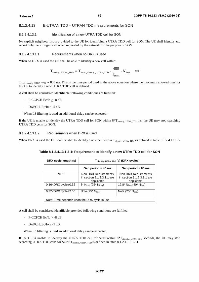
3GPP
69Release 8 3GPP TS 36.133 V8.9.0 (2010-03)
8.1.2.4.13 E-UTRAN TDD – UTRAN TDD measurements for SON
8.1.2.4.13.1 Identification of a new UTRA TDD cell for SON
No explicit neighbour list is provided to the UE for identifying a UTRA TDD cell for SON. The UE shall identify and report only the strongest cell when requested by the network for the purpose of SON.
8.1.2.4.13.1.1 Requirements when no DRX is used
When no DRX is used the UE shall be able to identify a new cell within:
msNFreq××=
inter1UTRA_TDD_identify_basic UTRA_TDDidentify, T
480TT
Tbasic_identify_UTRA_TDD = 800 ms. This is the time period used in the above equation where the maximum allowed time for the UE to identify a new UTRA TDD cell is defined.
A cell shall be considered identifiable following conditions are fulfilled:
- P-CCPCH Ec/Io > -8 dB,
- DwPCH_Ec/Io > -5 dB.
When L3 filtering is used an additional delay can be expected.
If the UE is unable to identify the UTRA TDD cell for SON within 8*Tidentify, UTRA_TDD ms, the UE may stop searching UTRA TDD cells for SON.
8.1.2.4.13.1.2 Requirements when DRX is used
When DRX is used the UE shall be able to identify a new cell within Tidentify, UTRA_TDD as defined in table 8.1.2.4.13.1.2-1.
Table 8.1.2.4.13.1.2-1: Requirement to identify a new UTRA TDD cell for SON
DRX cycle length (s) Tidentify, UTRA_TDD (s) (DRX cycles)
Gap period = 40 ms Gap period = 80 ms
≤0.16 Non DRX Requirements in section 8.1.2.3.1.1 are
applicable
Non DRX Requirements in section 8.1.2.3.1.1 are
applicable 0.16<DRX cycle≤0.32 8* Nfreq (25* Nfreq) 12.8* Nfreq (40* Nfreq)
0.32<DRX cycle≤2.56 Note (25* Nfreq) Note (25* Nfreq)
Note: Time depends upon the DRX cycle in use
A cell shall be considered identifiable provided following conditions are fulfilled:
- P-CCPCH Ec/Io > -8 dB,
- DwPCH_Ec/Io > -5 dB.
When L3 filtering is used an additional delay can be expected.
If the UE is unable to identify the UTRA TDD cell for SON within 8*Tidentify, UTRA_TDD seconds, the UE may stop searching UTRA TDD cells for SON; Tidentify, UTRA_TDD is defined in table 8.1.2.4.13.1.2-1.
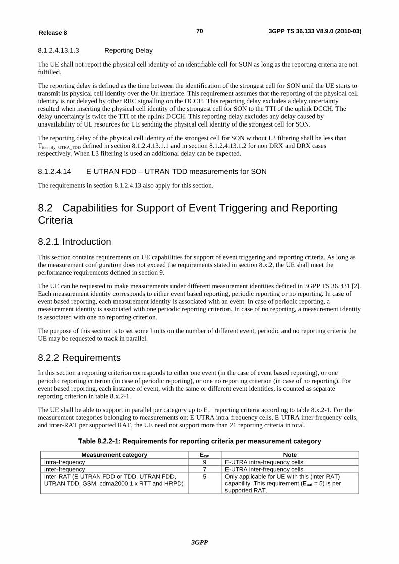
3GPP
70Release 8 3GPP TS 36.133 V8.9.0 (2010-03)
8.1.2.4.13.1.3 Reporting Delay
The UE shall not report the physical cell identity of an identifiable cell for SON as long as the reporting criteria are not fulfilled.
The reporting delay is defined as the time between the identification of the strongest cell for SON until the UE starts to transmit its physical cell identity over the Uu interface. This requirement assumes that the reporting of the physical cell identity is not delayed by other RRC signalling on the DCCH. This reporting delay excludes a delay uncertainty resulted when inserting the physical cell identity of the strongest cell for SON to the TTI of the uplink DCCH. The delay uncertainty is twice the TTI of the uplink DCCH. This reporting delay excludes any delay caused by unavailability of UL resources for UE sending the physical cell identity of the strongest cell for SON.
The reporting delay of the physical cell identity of the strongest cell for SON without L3 filtering shall be less than Tidentify, UTRA_TDD defined in section 8.1.2.4.13.1.1 and in section 8.1.2.4.13.1.2 for non DRX and DRX cases respectively. When L3 filtering is used an additional delay can be expected.
8.1.2.4.14 E-UTRAN FDD – UTRAN TDD measurements for SON
The requirements in section 8.1.2.4.13 also apply for this section.
8.2 Capabilities for Support of Event Triggering and Reporting Criteria
8.2.1 Introduction This section contains requirements on UE capabilities for support of event triggering and reporting criteria. As long as the measurement configuration does not exceed the requirements stated in section 8.x.2, the UE shall meet the performance requirements defined in section 9.
The UE can be requested to make measurements under different measurement identities defined in 3GPP TS 36.331 [2]. Each measurement identity corresponds to either event based reporting, periodic reporting or no reporting. In case of event based reporting, each measurement identity is associated with an event. In case of periodic reporting, a measurement identity is associated with one periodic reporting criterion. In case of no reporting, a measurement identity is associated with one no reporting criterion.
The purpose of this section is to set some limits on the number of different event, periodic and no reporting criteria the UE may be requested to track in parallel.
8.2.2 Requirements In this section a reporting criterion corresponds to either one event (in the case of event based reporting), or one periodic reporting criterion (in case of periodic reporting), or one no reporting criterion (in case of no reporting). For event based reporting, each instance of event, with the same or different event identities, is counted as separate reporting criterion in table 8.x.2-1.
The UE shall be able to support in parallel per category up to Ecat reporting criteria according to table 8.x.2-1. For the measurement categories belonging to measurements on: E-UTRA intra-frequency cells, E-UTRA inter frequency cells, and inter-RAT per supported RAT, the UE need not support more than 21 reporting criteria in total.
Table 8.2.2-1: Requirements for reporting criteria per measurement category
Measurement category Ecat Note Intra-frequency 9 E-UTRA intra-frequency cells Inter-frequency 7 E-UTRA inter-frequency cells Inter-RAT (E-UTRAN FDD or TDD, UTRAN FDD, UTRAN TDD, GSM, cdma2000 1 x RTT and HRPD)
5 Only applicable for UE with this (inter-RAT) capability. This requirement (Ecat = 5) is per supported RAT.
3GPP
71Release 8 3GPP TS 36.133 V8.9.0 (2010-03)
9 Measurements performance requirements for UE One of the key services provided by the physical layer is the measurements used to trigger or perform a multitude of functions. Both the UE and the E-UTRAN are required to perform measurements. The physical layer measurement model and a complete list of measurements is specified in TBD. The physical layer measurements for are described and defined in [4]. In this clause for each measurement the relevant requirements on the measurement period, reporting range, granularity and performance in terms of accuracy are specified.
Since the UE reference sensitivity requirements are different depending on supported band, this is noted in each case with definition of the range Io for each frequency band. Definitions of each frequency bands can be found in [5].
The accuracy requirements in this clause are applicable for AWGN radio propagation conditions and assume independent interference (noise) at each receiver antenna port.
[Editor’s Note: Requirements for multiple Tx antennas are still FFS. So far only 1Tx antenna case has been considered]
9.1 E-UTRAN measurements The requirements in this clause are applicable for a UE:
- in state RRC_CONNECTED
- performing measurements with appropriate measurement gaps as defined in Section 8.1.2.1.
- that is synchronised to the cell that is measured.
The reported measurement result after layer 1 filtering shall be an estimate of the average value of the measured quantity over the measurement period. The reference point for the measurement result after layer 1 filtering is referred to as point B in the measurement model described in TBD.
The accuracy requirements in this clause are valid for the reported measurement result after layer 1 filtering. The accuracy requirements are verified from the measurement report at point D in the measurement model having the higher layer filtering disabled.
9.1.2 Intra-frequency RSRP Accuracy Requirements
9.1.2.1 Absolute RSRP Accuracy
The absolute accuracy of RSRP is defined as the RSRP measured from a cell on the same frequency as that of the serving cell.
The accuracy requirements in Table 9.1.2.1-1 are valid under the following conditions:
Cell specific reference signals are transmitted either from one, two or four antenna ports.
Conditions defined in 36.101 Section 7.3 for reference sensitivity are fulfilled.
RSRP|dBm³ -127 dBm for Bands 1, 4, 6, 10, 11, 33, 34, 35, 36, 37, 38, 39, 40,
RSRP|dBm³ -126 dBm for Bands 9,
RSRP|dBm³ -125 dBm for Bands 2, 5, 7, 17,
RSRP|dBm³ -124 dBm for Bands 3, 8, 12, 13, 14.
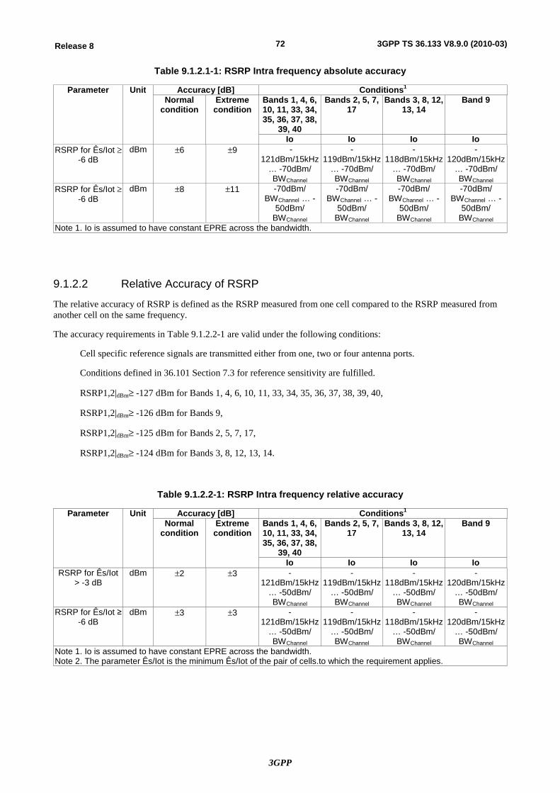
3GPP
72Release 8 3GPP TS 36.133 V8.9.0 (2010-03)
Table 9.1.2.1-1: RSRP Intra frequency absolute accuracy
Parameter Unit Accuracy [dB] Conditions1 Normal
condition Extreme condition
Bands 1, 4, 6, 10, 11, 33, 34, 35, 36, 37, 38,
39, 40
Bands 2, 5, 7, 17
Bands 3, 8, 12, 13, 14
Band 9
Io Io Io Io RSRP for Ês/Iot ³
-6 dB dBm ±6 ±9 -
121dBm/15kHz … -70dBm/ BWChannel
-119dBm/15kHz
… -70dBm/ BWChannel
-118dBm/15kHz
… -70dBm/ BWChannel
-120dBm/15kHz
… -70dBm/ BWChannel
RSRP for Ês/Iot ³ -6 dB
dBm ±8 ±11 -70dBm/ BWChannel … -
50dBm/ BWChannel
-70dBm/ BWChannel … -
50dBm/ BWChannel
-70dBm/ BWChannel … -
50dBm/ BWChannel
-70dBm/ BWChannel … -
50dBm/ BWChannel
Note 1. Io is assumed to have constant EPRE across the bandwidth.
9.1.2.2 Relative Accuracy of RSRP
The relative accuracy of RSRP is defined as the RSRP measured from one cell compared to the RSRP measured from another cell on the same frequency.
The accuracy requirements in Table 9.1.2.2-1 are valid under the following conditions:
Cell specific reference signals are transmitted either from one, two or four antenna ports.
Conditions defined in 36.101 Section 7.3 for reference sensitivity are fulfilled.
RSRP1,2|dBm³ -127 dBm for Bands 1, 4, 6, 10, 11, 33, 34, 35, 36, 37, 38, 39, 40,
RSRP1,2|dBm³ -126 dBm for Bands 9,
RSRP1,2|dBm³ -125 dBm for Bands 2, 5, 7, 17,
RSRP1,2|dBm³ -124 dBm for Bands 3, 8, 12, 13, 14.
Table 9.1.2.2-1: RSRP Intra frequency relative accuracy
Parameter Unit Accuracy [dB] Conditions1 Normal
condition Extreme condition
Bands 1, 4, 6, 10, 11, 33, 34, 35, 36, 37, 38,
39, 40
Bands 2, 5, 7, 17
Bands 3, 8, 12, 13, 14
Band 9
Io Io Io Io RSRP for Ês/Iot
> -3 dB dBm ±2 ±3 -
121dBm/15kHz … -50dBm/ BWChannel
-119dBm/15kHz
… -50dBm/ BWChannel
-118dBm/15kHz
… -50dBm/ BWChannel
-120dBm/15kHz
… -50dBm/ BWChannel
RSRP for Ês/Iot ≥ -6 dB
dBm ±3 ±3 -121dBm/15kHz
… -50dBm/ BWChannel
-119dBm/15kHz
… -50dBm/ BWChannel
-118dBm/15kHz
… -50dBm/ BWChannel
-120dBm/15kHz
… -50dBm/ BWChannel
Note 1. Io is assumed to have constant EPRE across the bandwidth. Note 2. The parameter Ês/Iot is the minimum Ês/Iot of the pair of cells.to which the requirement applies.
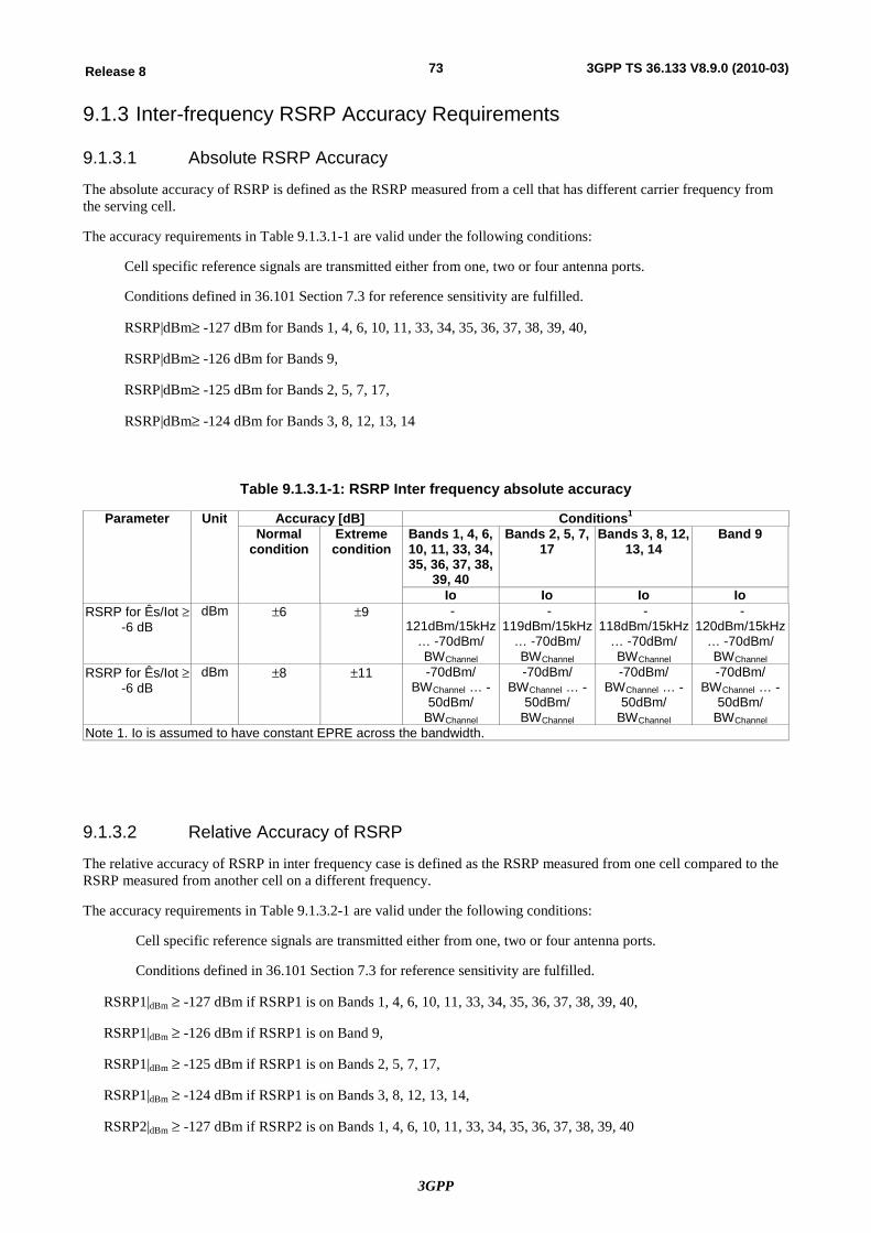
3GPP
73Release 8 3GPP TS 36.133 V8.9.0 (2010-03)
9.1.3 Inter-frequency RSRP Accuracy Requirements
9.1.3.1 Absolute RSRP Accuracy
The absolute accuracy of RSRP is defined as the RSRP measured from a cell that has different carrier frequency from the serving cell.
The accuracy requirements in Table 9.1.3.1-1 are valid under the following conditions:
Cell specific reference signals are transmitted either from one, two or four antenna ports.
Conditions defined in 36.101 Section 7.3 for reference sensitivity are fulfilled.
RSRP|dBm³ -127 dBm for Bands 1, 4, 6, 10, 11, 33, 34, 35, 36, 37, 38, 39, 40,
RSRP|dBm³ -126 dBm for Bands 9,
RSRP|dBm³ -125 dBm for Bands 2, 5, 7, 17,
RSRP|dBm³ -124 dBm for Bands 3, 8, 12, 13, 14
Table 9.1.3.1-1: RSRP Inter frequency absolute accuracy
Parameter Unit Accuracy [dB] Conditions1 Normal
condition Extreme condition
Bands 1, 4, 6, 10, 11, 33, 34, 35, 36, 37, 38,
39, 40
Bands 2, 5, 7, 17
Bands 3, 8, 12, 13, 14
Band 9
Io Io Io Io RSRP for Ês/Iot ³
-6 dB dBm ±6 ±9 -
121dBm/15kHz … -70dBm/ BWChannel
-119dBm/15kHz
… -70dBm/ BWChannel
-118dBm/15kHz
… -70dBm/ BWChannel
-120dBm/15kHz
… -70dBm/ BWChannel
RSRP for Ês/Iot ³ -6 dB
dBm ±8 ±11 -70dBm/ BWChannel … -
50dBm/ BWChannel
-70dBm/ BWChannel … -
50dBm/ BWChannel
-70dBm/ BWChannel … -
50dBm/ BWChannel
-70dBm/ BWChannel … -
50dBm/ BWChannel
Note 1. Io is assumed to have constant EPRE across the bandwidth.
9.1.3.2 Relative Accuracy of RSRP
The relative accuracy of RSRP in inter frequency case is defined as the RSRP measured from one cell compared to the RSRP measured from another cell on a different frequency.
The accuracy requirements in Table 9.1.3.2-1 are valid under the following conditions:
Cell specific reference signals are transmitted either from one, two or four antenna ports.
Conditions defined in 36.101 Section 7.3 for reference sensitivity are fulfilled.
RSRP1|dBm ³ -127 dBm if RSRP1 is on Bands 1, 4, 6, 10, 11, 33, 34, 35, 36, 37, 38, 39, 40,
RSRP1|dBm ³ -126 dBm if RSRP1 is on Band 9,
RSRP1|dBm ³ -125 dBm if RSRP1 is on Bands 2, 5, 7, 17,
RSRP1|dBm ³ -124 dBm if RSRP1 is on Bands 3, 8, 12, 13, 14,
RSRP2|dBm ³ -127 dBm if RSRP2 is on Bands 1, 4, 6, 10, 11, 33, 34, 35, 36, 37, 38, 39, 40
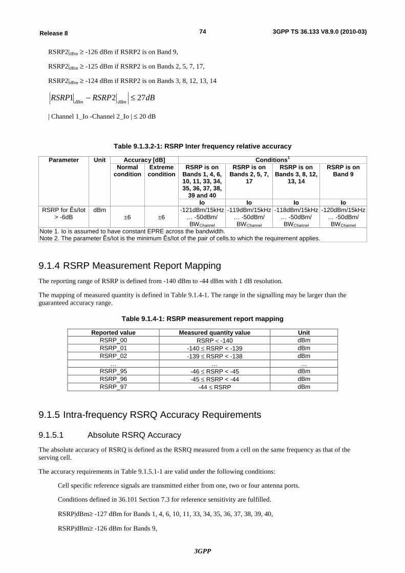
3GPP
74Release 8 3GPP TS 36.133 V8.9.0 (2010-03)
RSRP2|dBm ³ -126 dBm if RSRP2 is on Band 9,
RSRP2|dBm ³ -125 dBm if RSRP2 is on Bands 2, 5, 7, 17,
RSRP2|dBm ³ -124 dBm if RSRP2 is on Bands 3, 8, 12, 13, 14
dBRSRPRSRPdBmdBm
2721 £-
| Channel 1_Io -Channel 2_Io | £ 20 dB
Table 9.1.3.2-1: RSRP Inter frequency relative accuracy
Parameter Unit Accuracy [dB] Conditions1 Normal
condition Extreme condition
RSRP is on Bands 1, 4, 6, 10, 11, 33, 34, 35, 36, 37, 38,
39 and 40
RSRP is on Bands 2, 5, 7,
17
RSRP is on Bands 3, 8, 12,
13, 14
RSRP is on Band 9
Io Io Io Io RSRP for Ês/Iot
> -6dB dBm
±6 ±6 -121dBm/15kHz
… -50dBm/ BWChannel
-119dBm/15kHz … -50dBm/ BWChannel
-118dBm/15kHz … -50dBm/ BWChannel
-120dBm/15kHz … -50dBm/ BWChannel
Note 1. Io is assumed to have constant EPRE across the bandwidth. Note 2. The parameter Ês/Iot is the minimum Ês/Iot of the pair of cells.to which the requirement applies.
9.1.4 RSRP Measurement Report Mapping The reporting range of RSRP is defined from -140 dBm to -44 dBm with 1 dB resolution.
The mapping of measured quantity is defined in Table 9.1.4-1. The range in the signalling may be larger than the guaranteed accuracy range.
Table 9.1.4-1: RSRP measurement report mapping
Reported value Measured quantity value Unit RSRP_00 RSRP < -140 dBm RSRP_01 -140 £ RSRP < -139 dBm RSRP_02 -139 £ RSRP < -138 dBm
… … … RSRP_95 -46 £ RSRP < -45 dBm RSRP_96 -45 £ RSRP < -44 dBm RSRP_97 -44 £ RSRP dBm
9.1.5 Intra-frequency RSRQ Accuracy Requirements
9.1.5.1 Absolute RSRQ Accuracy
The absolute accuracy of RSRQ is defined as the RSRQ measured from a cell on the same frequency as that of the serving cell.
The accuracy requirements in Table 9.1.5.1-1 are valid under the following conditions:
Cell specific reference signals are transmitted either from one, two or four antenna ports.
Conditions defined in 36.101 Section 7.3 for reference sensitivity are fulfilled.
RSRP|dBm³ -127 dBm for Bands 1, 4, 6, 10, 11, 33, 34, 35, 36, 37, 38, 39, 40,
RSRP|dBm³ -126 dBm for Bands 9,
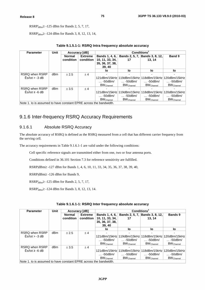
3GPP
75Release 8 3GPP TS 36.133 V8.9.0 (2010-03)
RSRP|dBm³ -125 dBm for Bands 2, 5, 7, 17,
RSRP|dBm³ -124 dBm for Bands 3, 8, 12, 13, 14,
Table 9.1.5.1-1: RSRQ Intra frequency absolute accuracy
Parameter Unit Accuracy [dB] Conditions1 Normal
condition Extreme condition
Bands 1, 4, 6, 10, 11, 33, 34, 35, 36, 37, 38,
39, 40
Bands 2, 5, 7, 17
Bands 3, 8, 12, 13, 14
Band 9
Io Io Io Io RSRQ when RSRP
Ês/Iot > -3 dB dBm ± 2.5 ± 4 -
121dBm/15kHz … -50dBm/ BWChannel
-119dBm/15kHz
… -50dBm/ BWChannel
-118dBm/15kHz
… -50dBm/ BWChannel
-120dBm/15kHz
… -50dBm/ BWChannel
RSRQ when RSRP Ês/Iot ≥ -6 dB
dBm ± 3.5 ± 4 -121dBm/15kHz
… -50dBm/ BWChannel
-119dBm/15kHz
… -50dBm/ BWChannel
-118dBm/15kHz
… -50dBm/ BWChannel
-120dBm/15kHz
… -50dBm/ BWChannel
Note 1. Io is assumed to have constant EPRE across the bandwidth.
9.1.6 Inter-frequency RSRQ Accuracy Requirements
9.1.6.1 Absolute RSRQ Accuracy
The absolute accuracy of RSRQ is defined as the RSRQ measured from a cell that has different carrier frequency from the serving cell.
The accuracy requirements in Table 9.1.6.1-1 are valid under the following conditions:
Cell specific reference signals are transmitted either from one, two or four antenna ports.
Conditions defined in 36.101 Section 7.3 for reference sensitivity are fulfilled.
RSRP|dBm³ -127 dBm for Bands 1, 4, 6, 10, 11, 33, 34, 35, 36, 37, 38, 39, 40,
RSRP|dBm³ -126 dBm for Bands 9,
RSRP|dBm³ -125 dBm for Bands 2, 5, 7, 17,
RSRP|dBm³ -124 dBm for Bands 3, 8, 12, 13, 14.
Table 9.1.6.1-1: RSRQ Inter frequency absolute accuracy
Parameter Unit Accuracy [dB] Conditions1 Normal
condition Extreme condition
Bands 1, 4, 6, 10, 11, 33, 34, 35, 36, 37, 38,
39, 40
Bands 2, 5, 7, 17
Bands 3, 8, 12, 13, 14
Bands 9
Io Io Io Io RSRQ when RSRP
Ês/Iot > -3 dB dBm ± 2.5 ± 4 -
121dBm/15kHz … -50dBm/ BWChannel
-119dBm/15kHz
… -50dBm/ BWChannel
-118dBm/15kHz
… -50dBm/ BWChannel
-120dBm/15kHz
… -50dBm/ BWChannel
RSRQ when RSRP Ês/Iot ≥ -6 dB
dBm ± 3.5 ± 4 -121dBm/15kHz
… -50dBm/ BWChannel
-119dBm/15kHz
… -50dBm/ BWChannel
-118dBm/15kHz
… -50dBm/ BWChannel
-120dBm/15kHz
… -50dBm/ BWChannel
Note 1. Io is assumed to have constant EPRE across the bandwidth.
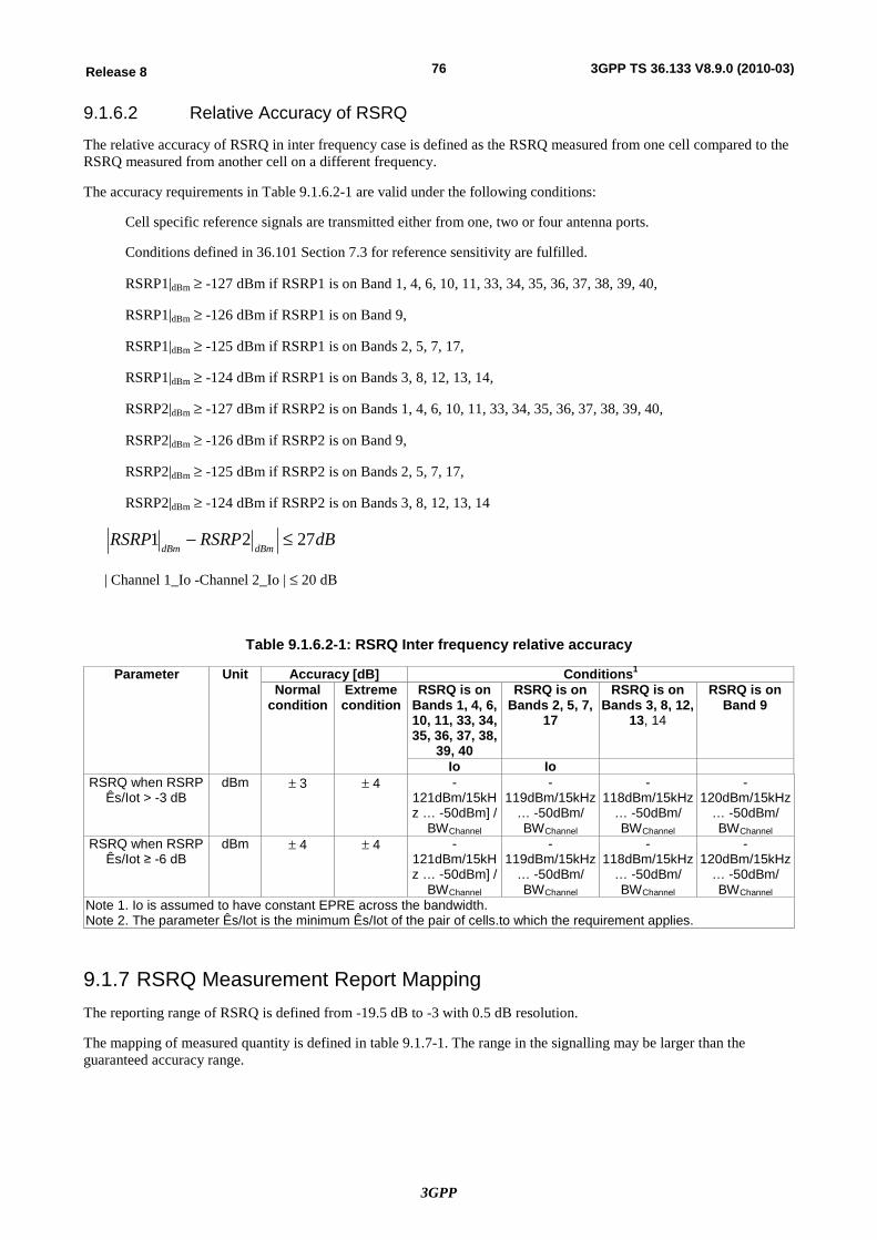
3GPP
76Release 8 3GPP TS 36.133 V8.9.0 (2010-03)
9.1.6.2 Relative Accuracy of RSRQ
The relative accuracy of RSRQ in inter frequency case is defined as the RSRQ measured from one cell compared to the RSRQ measured from another cell on a different frequency.
The accuracy requirements in Table 9.1.6.2-1 are valid under the following conditions:
Cell specific reference signals are transmitted either from one, two or four antenna ports.
Conditions defined in 36.101 Section 7.3 for reference sensitivity are fulfilled.
RSRP1|dBm ³ -127 dBm if RSRP1 is on Band 1, 4, 6, 10, 11, 33, 34, 35, 36, 37, 38, 39, 40,
RSRP1|dBm ³ -126 dBm if RSRP1 is on Band 9,
RSRP1|dBm ³ -125 dBm if RSRP1 is on Bands 2, 5, 7, 17,
RSRP1|dBm ³ -124 dBm if RSRP1 is on Bands 3, 8, 12, 13, 14,
RSRP2|dBm ³ -127 dBm if RSRP2 is on Bands 1, 4, 6, 10, 11, 33, 34, 35, 36, 37, 38, 39, 40,
RSRP2|dBm ³ -126 dBm if RSRP2 is on Band 9,
RSRP2|dBm ³ -125 dBm if RSRP2 is on Bands 2, 5, 7, 17,
RSRP2|dBm ³ -124 dBm if RSRP2 is on Bands 3, 8, 12, 13, 14
dBRSRPRSRPdBmdBm
2721 £-
| Channel 1_Io -Channel 2_Io | £ 20 dB
Table 9.1.6.2-1: RSRQ Inter frequency relative accuracy
Parameter Unit Accuracy [dB] Conditions1 Normal
condition Extreme condition
RSRQ is on Bands 1, 4, 6, 10, 11, 33, 34, 35, 36, 37, 38,
39, 40
RSRQ is on Bands 2, 5, 7,
17
RSRQ is on Bands 3, 8, 12,
13, 14
RSRQ is on Band 9
Io Io RSRQ when RSRP
Ês/Iot > -3 dB dBm ± 3 ± 4 -
121dBm/15kHz … -50dBm] /
BWChannel
-119dBm/15kHz
… -50dBm/ BWChannel
-118dBm/15kHz
… -50dBm/ BWChannel
-120dBm/15kHz
… -50dBm/ BWChannel
RSRQ when RSRP Ês/Iot ≥ -6 dB
dBm ± 4 ± 4 -121dBm/15kHz … -50dBm] /
BWChannel
-119dBm/15kHz
… -50dBm/ BWChannel
-118dBm/15kHz
… -50dBm/ BWChannel
-120dBm/15kHz
… -50dBm/ BWChannel
Note 1. Io is assumed to have constant EPRE across the bandwidth. Note 2. The parameter Ês/Iot is the minimum Ês/Iot of the pair of cells.to which the requirement applies.
9.1.7 RSRQ Measurement Report Mapping The reporting range of RSRQ is defined from -19.5 dB to -3 with 0.5 dB resolution.
The mapping of measured quantity is defined in table 9.1.7-1. The range in the signalling may be larger than the guaranteed accuracy range.
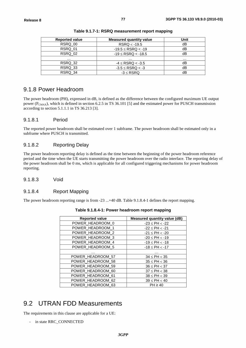
3GPP
77Release 8 3GPP TS 36.133 V8.9.0 (2010-03)
Table 9.1.7-1: RSRQ measurement report mapping
Reported value Measured quantity value Unit RSRQ_00 RSRQ < -19.5 dB RSRQ_01 -19.5 £ RSRQ < -19 dB RSRQ_02 -19 £ RSRQ < -18.5 dB
… … … RSRQ_32 -4 £ RSRQ < -3.5 dB RSRQ_33 -3.5 £ RSRQ < -3 dB RSRQ_34 -3 £ RSRQ dB
9.1.8 Power Headroom The power headroom (PH), expressed in dB, is defined as the difference between the configured maximum UE output power (PCMAX), which is defined in section 6.2.5 in TS 36.101 [5] and the estimated power for PUSCH transmission according to section 5.1.1.1 in TS 36.213 [3].
9.1.8.1 Period
The reported power headroom shall be estimated over 1 subframe. The power headroom shall be estimated only in a subframe where PUSCH is transmitted.
9.1.8.2 Reporting Delay
The power headroom reporting delay is defined as the time between the beginning of the power headroom reference period and the time when the UE starts transmitting the power headroom over the radio interface. The reporting delay of the power headroom shall be 0 ms, which is applicable for all configured triggering mechanisms for power headroom reporting.
9.1.8.3 Void
9.1.8.4 Report Mapping
The power headroom reporting range is from -23 ...+40 dB. Table 9.1.8.4-1 defines the report mapping.
Table 9.1.8.4-1: Power headroom report mapping
Reported value Measured quantity value (dB) POWER_HEADROOM_0 -23 £ PH < -22 POWER_HEADROOM_1 -22 £ PH < -21 POWER_HEADROOM_2 -21 £ PH < -20 POWER_HEADROOM_3 -20 £ PH < -19 POWER_HEADROOM_4 -19 £ PH < -18 POWER_HEADROOM_5 -18 £ PH < -17
¼ ¼ POWER_HEADROOM_57 34 £ PH < 35 POWER_HEADROOM_58 35 £ PH < 36 POWER_HEADROOM_59 36 £ PH < 37 POWER_HEADROOM_60 37 £ PH < 38 POWER_HEADROOM_61 38 £ PH < 39 POWER_HEADROOM_62 39 £ PH < 40 POWER_HEADROOM_63 PH ≥ 40
9.2 UTRAN FDD Measurements The requirements in this clause are applicable for a UE:
- in state RRC_CONNECTED
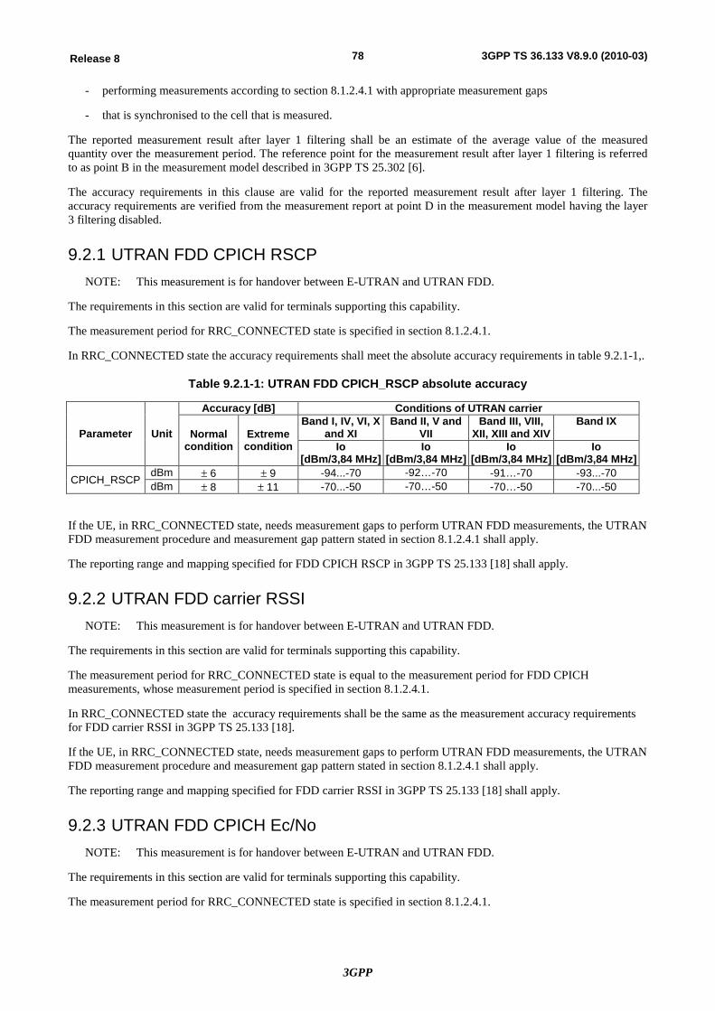
3GPP
78Release 8 3GPP TS 36.133 V8.9.0 (2010-03)
- performing measurements according to section 8.1.2.4.1 with appropriate measurement gaps
- that is synchronised to the cell that is measured.
The reported measurement result after layer 1 filtering shall be an estimate of the average value of the measured quantity over the measurement period. The reference point for the measurement result after layer 1 filtering is referred to as point B in the measurement model described in 3GPP TS 25.302 [6].
The accuracy requirements in this clause are valid for the reported measurement result after layer 1 filtering. The accuracy requirements are verified from the measurement report at point D in the measurement model having the layer 3 filtering disabled.
9.2.1 UTRAN FDD CPICH RSCP NOTE: This measurement is for handover between E-UTRAN and UTRAN FDD.
The requirements in this section are valid for terminals supporting this capability.
The measurement period for RRC_CONNECTED state is specified in section 8.1.2.4.1.
In RRC_CONNECTED state the accuracy requirements shall meet the absolute accuracy requirements in table 9.2.1-1,.
Table 9.2.1-1: UTRAN FDD CPICH_RSCP absolute accuracy
Parameter Unit
Accuracy [dB] Conditions of UTRAN carrier
Normal condition
Extreme condition
Band I, IV, VI, X and XI
Band II, V and VII
Band III, VIII, XII, XIII and XIV
Band IX
Io [dBm/3,84 MHz]
Io [dBm/3,84 MHz]
Io [dBm/3,84 MHz]
Io [dBm/3,84 MHz]
CPICH_RSCP dBm ± 6 ± 9 -94...-70 -92…-70 -91…-70 -93...-70 dBm ± 8 ± 11 -70...-50 -70…-50 -70…-50 -70...-50
If the UE, in RRC_CONNECTED state, needs measurement gaps to perform UTRAN FDD measurements, the UTRAN FDD measurement procedure and measurement gap pattern stated in section 8.1.2.4.1 shall apply.
The reporting range and mapping specified for FDD CPICH RSCP in 3GPP TS 25.133 [18] shall apply.
9.2.2 UTRAN FDD carrier RSSI NOTE: This measurement is for handover between E-UTRAN and UTRAN FDD.
The requirements in this section are valid for terminals supporting this capability.
The measurement period for RRC_CONNECTED state is equal to the measurement period for FDD CPICH measurements, whose measurement period is specified in section 8.1.2.4.1.
In RRC_CONNECTED state the accuracy requirements shall be the same as the measurement accuracy requirements for FDD carrier RSSI in 3GPP TS 25.133 [18].
If the UE, in RRC_CONNECTED state, needs measurement gaps to perform UTRAN FDD measurements, the UTRAN FDD measurement procedure and measurement gap pattern stated in section 8.1.2.4.1 shall apply.
The reporting range and mapping specified for FDD carrier RSSI in 3GPP TS 25.133 [18] shall apply.
9.2.3 UTRAN FDD CPICH Ec/No NOTE: This measurement is for handover between E-UTRAN and UTRAN FDD.
The requirements in this section are valid for terminals supporting this capability.
The measurement period for RRC_CONNECTED state is specified in section 8.1.2.4.1.
3GPP
79Release 8 3GPP TS 36.133 V8.9.0 (2010-03)
In RRC_CONNECTED state the accuracy requirements shall be the same as the inter-frequency measurement accuracy requirements for FDD CPICH Ec/No in 3GPP TS 25.133 [18].
If the UE, in RRC_CONNECTED state, needs measurement gaps to perform UTRAN FDD measurements, the UTRAN FDD measurement procedure and measurement gap pattern stated in section 8.1.2.4.1 shall apply.
The reporting range and mapping specified for FDD CPICH Ec/No in 3GPP TS 25.133 [18] shall apply.
9.3 UTRAN TDD Measurements The requirements in this clause are applicable for a UE:
- in state RRC_CONNECTED
- performing measurements according to section 8.1.2.4.3 with appropriate measurement gaps
- that is synchronised to the cell that is measured.
The reported measurement result after layer 1 filtering shall be an estimate of the average value of the measured quantity over the measurement period. The reference point for the measurement result after layer 1 filtering is referred to as point B in the measurement model described in 3GPP TS 25.302 [6].
The accuracy requirements in this clause are valid for the reported measurement result after layer 1 filtering. The accuracy requirements are verified from the measurement report at point D in the measurement model having the layer 3 filtering disabled.
9.3.1 UTRAN TDD P-CCPCH RSCP NOTE: This measurement is for handover between E-UTRAN and UTRAN TDD.
The requirements in this section are valid for terminals supporting this capability.
The measurement period for RRC_CONNECTED state is specified in section 8.1.2.4.3.
In RRC_CONNECTED state the accuracy requirements shall be the same as the inter-frequency measurement accuracy requirements for TDD P-CCPCH in 3GPP TS 25.123 [19].
If the UE, in RRC_CONNECTED state, needs measurement gaps to perform UTRAN TDD measurements, the UTRAN TDD measurement procedure and measurement gap pattern stated in section 8.1.2.4.3 shall apply.
The reporting range and mapping specified for TDD P-CCPCH RSCP in 3GPP TS 25.123 [19] shall apply.
9.3.2 UTRAN TDD carrier RSSI NOTE: This measurement is for handover between E-UTRAN and UTRAN TDD.
The requirements in this section are valid for terminals supporting this capability.
The measurement period for RRC_CONNECTED state is equal to the measurement period for TDD P-CCPCH RSCP measurement, whose measurement period is specified in section 8.1.2.4.3.
In RRC_CONNECTED state the accuracy requirements shall be the same as the inter-frequency measurement accuracy requirements for TDD carrier RSSI in 3GPP TS 25.123 [19].
If the UE, in RRC_CONNECTED state, needs measurement gaps to perform UTRAN TDD measurements, the UTRAN TDD measurement procedure and measurement gap pattern stated in section 8.1.2.4.3 shall apply.
The reporting range and mapping specified for TDD carrier RSSI in 3GPP TS 25.123 [19] shall apply.
3GPP
80Release 8 3GPP TS 36.133 V8.9.0 (2010-03)
9.3.3 Void
9.4 GSM Measurements The requirements in this clause are applicable for a UE:
- in state RRC_CONNECTED
- performing measurements according to section 8.1.2.4.5 with appropriate measurement gaps
- that is synchronised to the cell that is measured.
The reported measurement result after layer 1 filtering shall be an estimate of the average value of the measured quantity over the measurement period. The reference point for the measurement result after layer 1 filtering is referred to as point B in the measurement model described in 3GPP TS 25.302 [6].
The accuracy requirements in this clause are valid for the reported measurement result after layer 1 filtering. The accuracy requirements are verified from the measurement report at point D in the measurement model having the layer 3 filtering disabled.
9.4.1 GSM carrier RSSI NOTE: This measurement is for handover between E-UTRAN and GSM.
The requirements in this section are valid for terminals supporting this capability.
The measurement period for RRC_CONNECTED state is specified in section 8.1.2.4.5.
In RRC_CONNECTED state the measurement accuracy requirements for RXLEV in TS 45.008 [8] shall apply.
If the UE, in RRC_CONNECED state, needs measurement gaps to perform GSM measurements, the GSM measurement procedure and measurement gap pattern stated in section 8.1.2.4.5 shall apply.
The reporting range and mapping specified for RXLEV in TS 45.008 [8] shall apply.
9.5 CDMA2000 1x RTT Measurements The requirements in this clause are applicable for a UE:
- in RRC_CONNECTED state.
- synchronised to the cell that is measured.
9.5.1 CDMA2000 1x RTT Pilot Strength NOTE: This measurement is for handover between E-UTRAN and cdma2000 1 x RTT.
The requirements in this section are valid for terminals supporting this capability.
CDMA2000 1xRTT Pilot Strength defined in sub-clause 5.1.10 of [4] shall meet the performance requirement defined in sub-clause 3.2.4 of [14] on the cdma2000 1xRTT neighbour cells indicated by the serving eNode B.
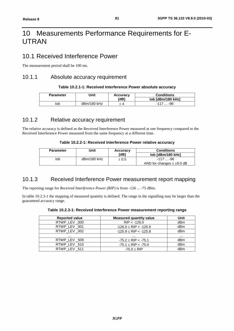
3GPP
81Release 8 3GPP TS 36.133 V8.9.0 (2010-03)
10 Measurements Performance Requirements for E-UTRAN
10.1 Received Interference Power The measurement period shall be 100 ms.
10.1.1 Absolute accuracy requirement
Table 10.2.1-1: Received Interference Power absolute accuracy
Parameter Unit Accuracy [dB]
Conditions Iob [dBm/180 kHz]
Iob dBm/180 kHz ± 4 -117 ... -96
10.1.2 Relative accuracy requirement The relative accuracy is defined as the Received Interference Power measured at one frequency compared to the Received Interference Power measured from the same frequency at a different time.
Table 10.2.2-1: Received Interference Power relative accuracy
Parameter Unit Accuracy [dB]
Conditions Iob [dBm/180 kHz]
Iob dBm/180 kHz ± 0.5 -117 ... -96 AND for changes £ ±9.0 dB
10.1.3 Received Interference Power measurement report mapping The reporting range for Received Interference Power (RIP) is from -126 ... -75 dBm.
In table 10.2.3-1 the mapping of measured quantity is defined. The range in the signalling may be larger than the guaranteed accuracy range.
Table 10.2.3-1: Received Interference Power measurement reporting range
Reported value Measured quantity value Unit RTWP_LEV _000 RIP < -126.0 dBm RTWP_LEV _001 -126.0 £ RIP < -125.9 dBm RTWP_LEV _002 -125.9 £ RIP < -125.8 dBm
… … … RTWP_LEV _509 -75.2 £ RIP < -75.1 dBm RTWP_LEV _510 -75.1 £ RIP < -75.0 dBm RTWP_LEV _511 -75.0 £ RIP dBm
3GPP
82Release 8 3GPP TS 36.133 V8.9.0 (2010-03)
Annex A (normative): Test Cases
A.1 Purpose of annex This Annex specifies test specific parameters for some of the functional requirements in sections 4 to 9. The tests provide additional information to how the requirements should be interpreted for the purpose of conformance testing. The tests in this Annex are described such that one functional requirement may be tested in one or several test and one test may verify several requirements. Some requirements may lack a test.
The conformance tests are specified in TS 36.521-3 [23]. Statistical interpretation of the requirements is described in Annex A.2.
A.2 Requirement classification for statistical testing Requirements in this specification are either expressed as absolute requirements with a single value stating the requirement, or expressed as a success rate. There are no provisions for the statistical variations that will occur when the parameter is tested.
Annex A outlines the tests in more detail and lists the test parameters needed. The test will result in an outcome of a test variable value for the device under test (DUT) inside or outside the test limit. Overall, the probability of a "good" DUT being inside the test limit(s) and the probability of a "bad" DUT being outside the test limit(s) should be as high as possible. For this reason, when selecting the test variable and the test limit(s), the statistical nature of the test is accounted for.
The statistical nature depends on the type of requirement. Some have large statistical variations, while others are not statistical in nature at all. When testing a parameter with a statistical nature, a confidence level is set. This establishes the probability that a DUT passing the test actually meets the requirements and determines how many times a test has to be repeated and what the pass and fail criteria are. Those aspects are not covered by TS 36.133. The details of the tests on how many times to run it and how to establish confidence in the tests are described in TS 36.521-3 [23]. This Annex establishes the variable to be used in the test and whether it can be viewed as statistical in nature or not.
A.2.1 Types of requirements in TS 36.133
A.2.1.1 Time and delay requirements on UE higher layer actions A very large part of the RRM requirements are delay requirements:
- In E-UTRAN RRC_IDLE state mobility (clause A.4) there is cell re-selection delay.
- In E-UTRAN RRC_CONNECTED state mobility (clauses A.5 and A.8) there is handover delay, cell search delay and measurement reporting delay.
- In RRC Connection Control (clause A.6) there is RRC re-establishment delay.
All have in common that the UE is required to perform an action observable in higher layers (e.g. camp on the correct cell) within a certain time after a specific event (e.g. when a new strong pilot or reference signal appears). The delay time is statistical in nature for several reasons, among others that several of the measurements are performed by the UE in a fading radio environment.
The variations make a strict limit unsuitable for a test. Instead there is a condition set for a correct action by the UE, e.g. that the UE shall camp on the correct cell within X seconds. Then the rate of correct events is observed during repeated tests and a limit is set on the rate of correct events, usually 90% correct events are required. How the limit is applied in the test depends on the confidence required, further detailed are in TS 36.521-3 [23].
3GPP
83Release 8 3GPP TS 36.133 V8.9.0 (2010-03)
A.2.1.2 Measurements of power levels, relative powers and time A very large number of requirements are on measurements that the UE performs:
- In E-UTRAN RRC_CONNECTED state mobility (clause A.5) there are measurement reports.
- In Measurement Performance Requirements (clause A.9) there are requirements for all type of measurements.
The accuracy requirements on measurements are expressed in this specification as a fixed limit (e.g. +/-X dB), but the measurement error will have a distribution that is not easily confined in fixed limits. Assuming a Gaussian distribution of the error, the limits will have to be set at +/-3.29s if the probability of failing a "good DUT" in a single test is to be kept at 0.1%. It is more reasonable to set the limit tighter and test the DUT by counting the rate of measurements that are within the limits, in a way similar to the requirements on delay.
A.2.1.3 Implementation requirements A few requirements are strict actions the UE should take or capabilities the UE should have, without any allowance for deviations. These requirements are absolute and should be tested as such. Examples are:
- "Event triggered report rate" in E-UTRAN RRC_CONNECTED state mobility (clauses A.5 and A.8)
- "Correct behaviour at time-out" in RRC connection control (clause A.6)
A.2.1.4 Physical layer timing requirements There are requirements on Timing and Signaling Characteristics (clauses A.7). There are both absolute and relative limits on timing accuracy depending upon the type of requirement. Examples are:
- Initial Transmit Timing (clause A.7.1) has an absolute limit on timing accuracy.
- Timing Advance (clause A.7.2) has a relative limit on timing accuracy.
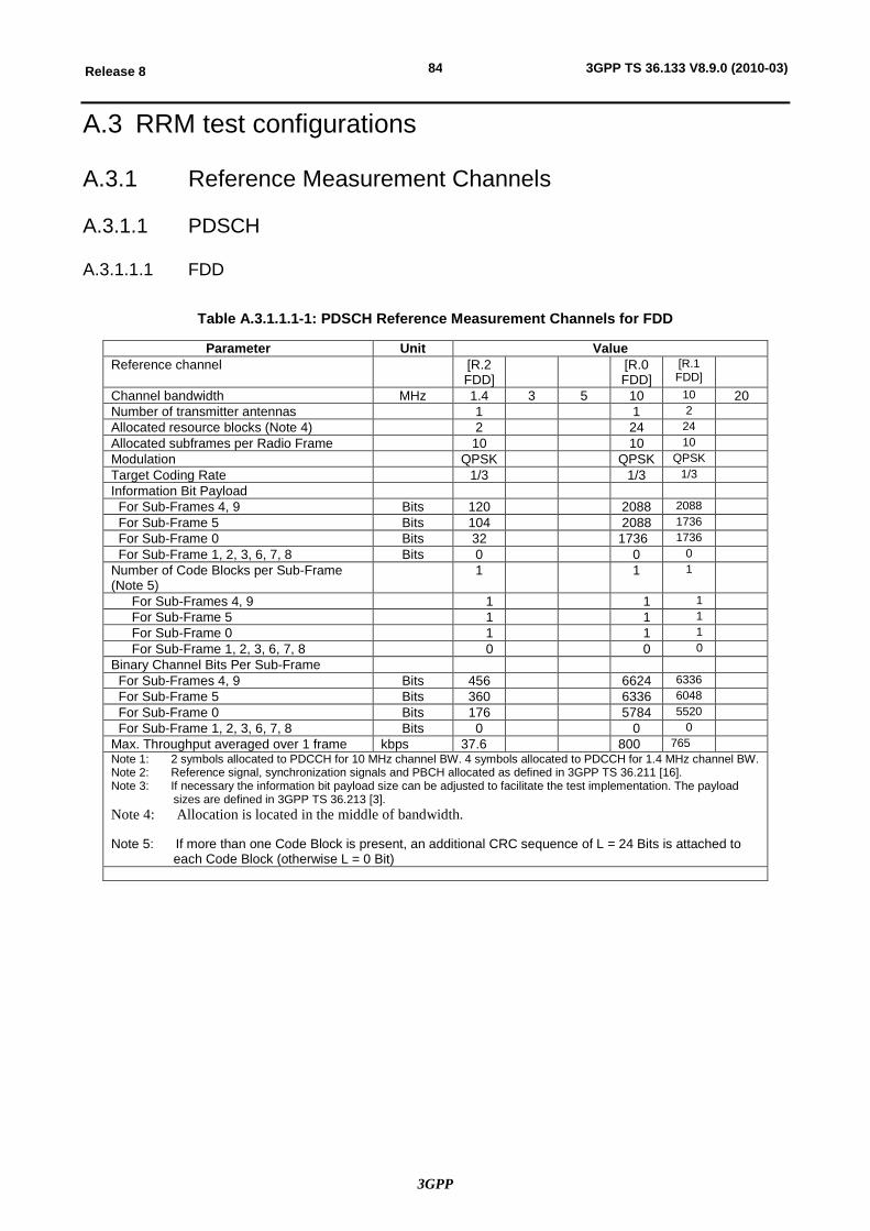
3GPP
84Release 8 3GPP TS 36.133 V8.9.0 (2010-03)
A.3 RRM test configurations
A.3.1 Reference Measurement Channels
A.3.1.1 PDSCH
A.3.1.1.1 FDD
Table A.3.1.1.1-1: PDSCH Reference Measurement Channels for FDD
Parameter Unit Value Reference channel [R.2
FDD] [R.0
FDD] [R.1 FDD]
Channel bandwidth MHz 1.4 3 5 10 10 20 Number of transmitter antennas 1 1 2 Allocated resource blocks (Note 4) 2 24 24 Allocated subframes per Radio Frame 10 10 10 Modulation QPSK QPSK QPSK Target Coding Rate 1/3 1/3 1/3 Information Bit Payload For Sub-Frames 4, 9 Bits 120 2088 2088 For Sub-Frame 5 Bits 104 2088 1736 For Sub-Frame 0 Bits 32 1736 1736 For Sub-Frame 1, 2, 3, 6, 7, 8 Bits 0 0 0 Number of Code Blocks per Sub-Frame (Note 5)
1 1 1
For Sub-Frames 4, 9 1 1 1 For Sub-Frame 5 1 1 1 For Sub-Frame 0 1 1 1 For Sub-Frame 1, 2, 3, 6, 7, 8 0 0 0
Binary Channel Bits Per Sub-Frame For Sub-Frames 4, 9 Bits 456 6624 6336 For Sub-Frame 5 Bits 360 6336 6048 For Sub-Frame 0 Bits 176 5784 5520 For Sub-Frame 1, 2, 3, 6, 7, 8 Bits 0 0 0 Max. Throughput averaged over 1 frame kbps 37.6 800 765 Note 1: 2 symbols allocated to PDCCH for 10 MHz channel BW. 4 symbols allocated to PDCCH for 1.4 MHz channel BW. Note 2: Reference signal, synchronization signals and PBCH allocated as defined in 3GPP TS 36.211 [16]. Note 3: If necessary the information bit payload size can be adjusted to facilitate the test implementation. The payload
sizes are defined in 3GPP TS 36.213 [3]. Note 4: Allocation is located in the middle of bandwidth.
Note 5: If more than one Code Block is present, an additional CRC sequence of L = 24 Bits is attached to each Code Block (otherwise L = 0 Bit)
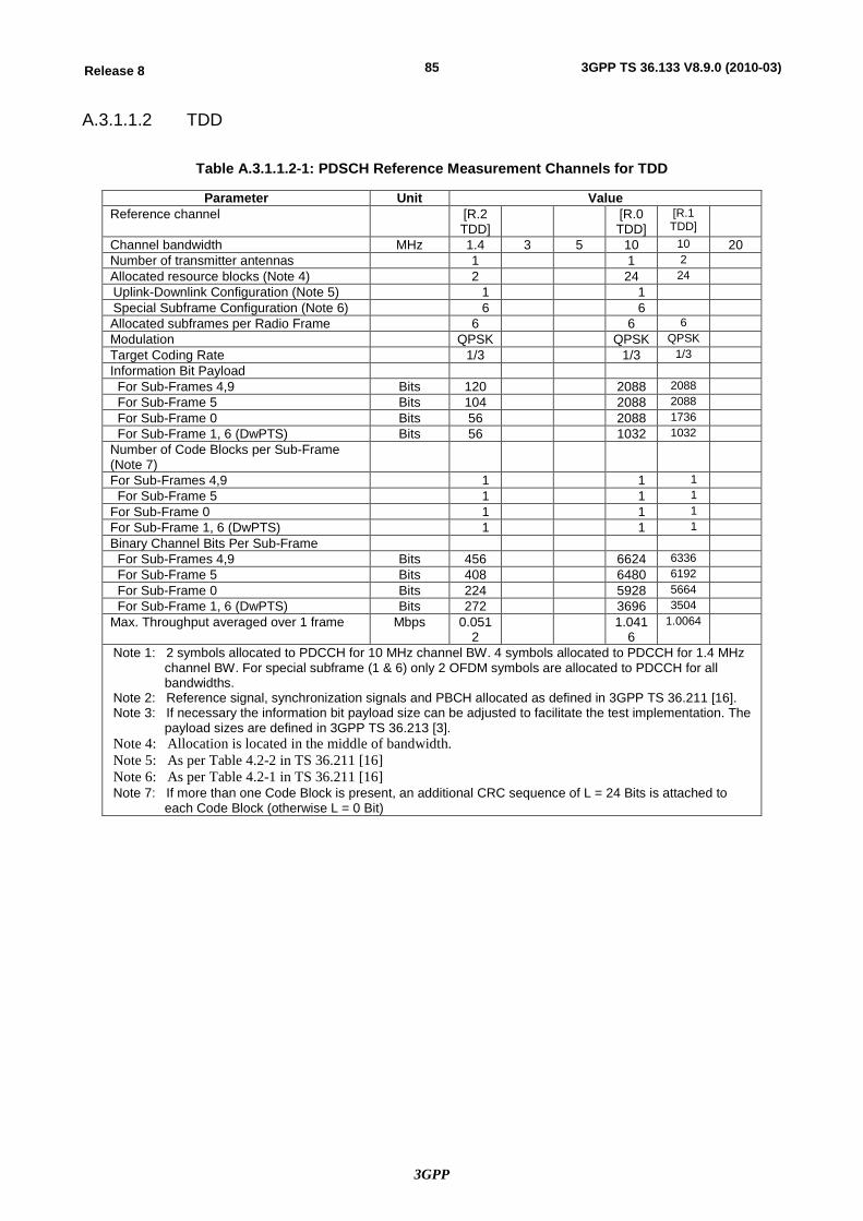
3GPP
85Release 8 3GPP TS 36.133 V8.9.0 (2010-03)
A.3.1.1.2 TDD
Table A.3.1.1.2-1: PDSCH Reference Measurement Channels for TDD
Parameter Unit Value Reference channel [R.2
TDD] [R.0
TDD] [R.1 TDD]
Channel bandwidth MHz 1.4 3 5 10 10 20 Number of transmitter antennas 1 1 2 Allocated resource blocks (Note 4) 2 24 24 Uplink-Downlink Configuration (Note 5) 1 1 Special Subframe Configuration (Note 6) 6 6 Allocated subframes per Radio Frame 6 6 6 Modulation QPSK QPSK QPSK Target Coding Rate 1/3 1/3 1/3 Information Bit Payload For Sub-Frames 4,9 Bits 120 2088 2088 For Sub-Frame 5 Bits 104 2088 2088 For Sub-Frame 0 Bits 56 2088 1736 For Sub-Frame 1, 6 (DwPTS) Bits 56 1032 1032 Number of Code Blocks per Sub-Frame (Note 7)
For Sub-Frames 4,9 1 1 1 For Sub-Frame 5 1 1 1 For Sub-Frame 0 1 1 1 For Sub-Frame 1, 6 (DwPTS) 1 1 1 Binary Channel Bits Per Sub-Frame For Sub-Frames 4,9 Bits 456 6624 6336 For Sub-Frame 5 Bits 408 6480 6192 For Sub-Frame 0 Bits 224 5928 5664 For Sub-Frame 1, 6 (DwPTS) Bits 272 3696 3504 Max. Throughput averaged over 1 frame Mbps 0.051
2 1.041
6 1.0064
Note 1: 2 symbols allocated to PDCCH for 10 MHz channel BW. 4 symbols allocated to PDCCH for 1.4 MHz channel BW. For special subframe (1 & 6) only 2 OFDM symbols are allocated to PDCCH for all bandwidths.
Note 2: Reference signal, synchronization signals and PBCH allocated as defined in 3GPP TS 36.211 [16]. Note 3: If necessary the information bit payload size can be adjusted to facilitate the test implementation. The
payload sizes are defined in 3GPP TS 36.213 [3]. Note 4: Allocation is located in the middle of bandwidth. Note 5: As per Table 4.2-2 in TS 36.211 [16] Note 6: As per Table 4.2-1 in TS 36.211 [16] Note 7: If more than one Code Block is present, an additional CRC sequence of L = 24 Bits is attached to
each Code Block (otherwise L = 0 Bit)
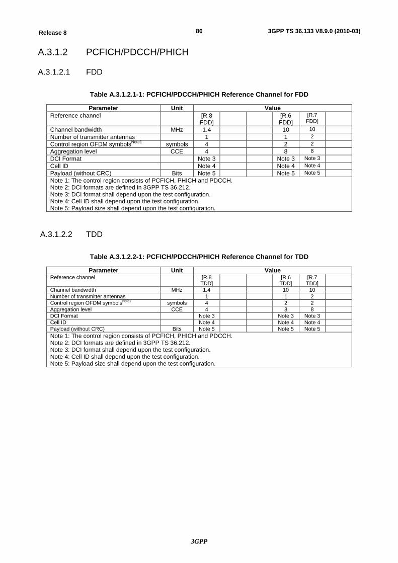
3GPP
86Release 8 3GPP TS 36.133 V8.9.0 (2010-03)
A.3.1.2 PCFICH/PDCCH/PHICH
A.3.1.2.1 FDD
Table A.3.1.2.1-1: PCFICH/PDCCH/PHICH Reference Channel for FDD
Parameter Unit Value Reference channel [R.8
FDD] [R.6
FDD] [R.7 FDD]
Channel bandwidth MHz 1.4 10 10 Number of transmitter antennas 1 1 2 Control region OFDM symbolsNote1 symbols 4 2 2 Aggregation level CCE 4 8 8 DCI Format Note 3 Note 3 Note 3 Cell ID Note 4 Note 4 Note 4 Payload (without CRC) Bits Note 5 Note 5 Note 5 Note 1: The control region consists of PCFICH, PHICH and PDCCH. Note 2: DCI formats are defined in 3GPP TS 36.212. Note 3: DCI format shall depend upon the test configuration. Note 4: Cell ID shall depend upon the test configuration. Note 5: Payload size shall depend upon the test configuration.
A.3.1.2.2 TDD
Table A.3.1.2.2-1: PCFICH/PDCCH/PHICH Reference Channel for TDD
Parameter Unit Value Reference channel [R.8
TDD] [R.6
TDD] [R.7 TDD]
Channel bandwidth MHz 1.4 10 10 Number of transmitter antennas 1 1 2 Control region OFDM symbolsNote1 symbols 4 2 2 Aggregation level CCE 4 8 8 DCI Format Note 3 Note 3 Note 3 Cell ID Note 4 Note 4 Note 4 Payload (without CRC) Bits Note 5 Note 5 Note 5 Note 1: The control region consists of PCFICH, PHICH and PDCCH. Note 2: DCI formats are defined in 3GPP TS 36.212. Note 3: DCI format shall depend upon the test configuration. Note 4: Cell ID shall depend upon the test configuration. Note 5: Payload size shall depend upon the test configuration.
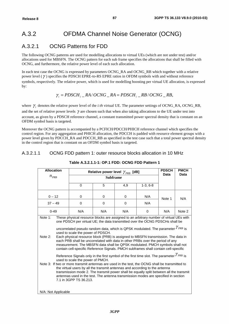
3GPP
87Release 8 3GPP TS 36.133 V8.9.0 (2010-03)
A.3.2 OFDMA Channel Noise Generator (OCNG)
A.3.2.1 OCNG Patterns for FDD The following OCNG patterns are used for modelling allocations to virtual UEs (which are not under test) and/or allocations used for MBSFN. The OCNG pattern for each sub frame specifies the allocations that shall be filled with OCNG, and furthermore, the relative power level of each such allocation.
In each test case the OCNG is expressed by parameters OCNG_RA and OCNG_RB which together with a relative power level (g ) specifies the PDSCH EPRE-to-RS EPRE ratios in OFDM symbols with and without reference symbols, respectively. The relative power, which is used for modelling boosting per virtual UE allocation, is expressed by:
,_/__/_ RBOCNGRBPDSCHRAOCNGRAPDSCH iii ==g
where ig denotes the relative power level of the i:th virtual UE. The parameter settings of OCNG_RA, OCNG_RB, and the set of relative power levels g are chosen such that when also taking allocations to the UE under test into account, as given by a PDSCH reference channel, a constant transmitted power spectral density that is constant on an OFDM symbol basis is targeted.
Moreover the OCNG pattern is accompanied by a PCFICH/PDCCH/PHICH reference channel which specifies the control region. For any aggregation and PHICH allocation, the PDCCH is padded with resource element groups with a power level given by PDCCH_RA and PDCCH_RB as specified in the test case such that a total power spectral density in the control region that is constant on an OFDM symbol basis is targeted.
A.3.2.1.1 OCNG FDD pattern 1: outer resource blocks allocation in 10 MHz
Table A.3.2.1.1-1: OP.1 FDD: OCNG FDD Pattern 1
Allocation
PRBn Relative power level PRBg [dB] PDSCH
Data PMCH Data
Subframe
0 5 4,9 1-3, 6-8
0 – 12
0
0
0
N/A Note 1 N/A
37 – 49 0 0 0 N/A
0-49 N/A N/A N/A 0 N/A Note 2
Note 1: These physical resource blocks are assigned to an arbitrary number of virtual UEs with one PDSCH per virtual UE; the data transmitted over the OCNG PDSCHs shall be
uncorrelated pseudo random data, which is QPSK modulated. The parameter PRBg is used to scale the power of PDSCH.
Note 2: Each physical resource block (PRB) is assigned to MBSFN transmission. The data in each PRB shall be uncorrelated with data in other PRBs over the period of any measurement. The MBSFN data shall be QPSK modulated. PMCH symbols shall not contain cell-specific Reference Signals. PMCH subframes shall contain cell-specific
Reference Signals only in the first symbol of the first time slot. The parameter PRBg is used to scale the power of PMCH.
Note 3: If two or more transmit antennas are used in the test, the OCNG shall be transmitted to the virtual users by all the transmit antennas and according to the antenna transmission mode 2. The transmit power shall be equally split between all the transmit antennas used in the test. The antenna transmission modes are specified in section 7.1 in 3GPP TS 36.213.
N/A: Not Applicable
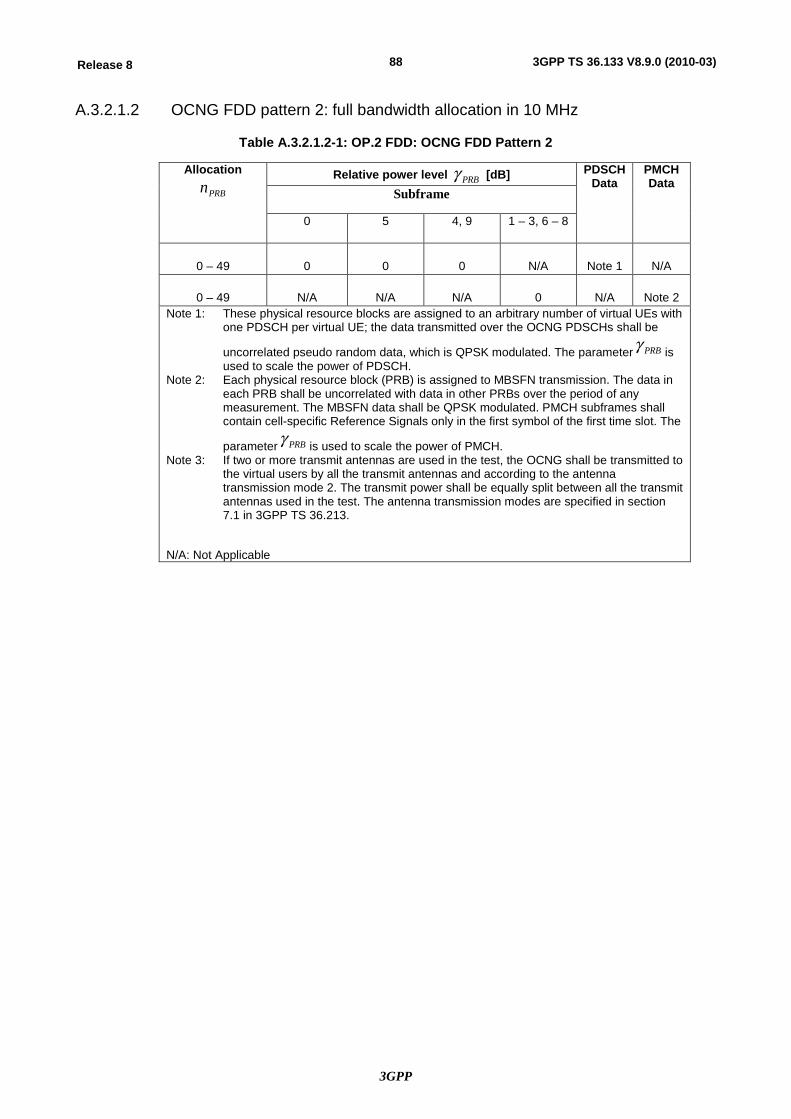
3GPP
88Release 8 3GPP TS 36.133 V8.9.0 (2010-03)
A.3.2.1.2 OCNG FDD pattern 2: full bandwidth allocation in 10 MHz
Table A.3.2.1.2-1: OP.2 FDD: OCNG FDD Pattern 2
Allocation
PRBn Relative power level PRBg [dB] PDSCH
Data PMCH Data
Subframe
0 5 4, 9 1 – 3, 6 – 8
0 – 49
0
0
0
N/A
Note 1
N/A
0 – 49
N/A
N/A
N/A
0
N/A
Note 2
Note 1: These physical resource blocks are assigned to an arbitrary number of virtual UEs with one PDSCH per virtual UE; the data transmitted over the OCNG PDSCHs shall be
uncorrelated pseudo random data, which is QPSK modulated. The parameter PRBg is used to scale the power of PDSCH.
Note 2: Each physical resource block (PRB) is assigned to MBSFN transmission. The data in each PRB shall be uncorrelated with data in other PRBs over the period of any measurement. The MBSFN data shall be QPSK modulated. PMCH subframes shall contain cell-specific Reference Signals only in the first symbol of the first time slot. The
parameter PRBg is used to scale the power of PMCH. Note 3: If two or more transmit antennas are used in the test, the OCNG shall be transmitted to
the virtual users by all the transmit antennas and according to the antenna transmission mode 2. The transmit power shall be equally split between all the transmit antennas used in the test. The antenna transmission modes are specified in section 7.1 in 3GPP TS 36.213.
N/A: Not Applicable
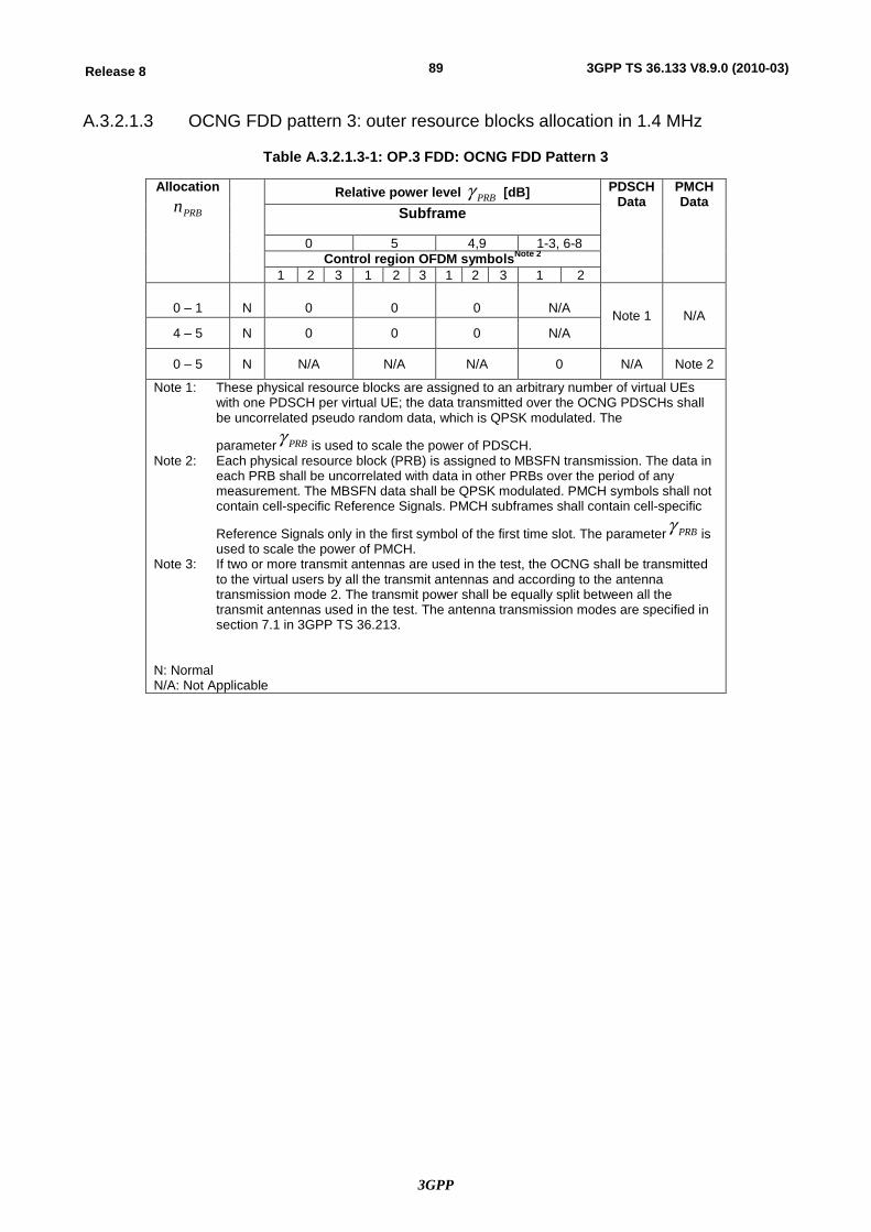
3GPP
89Release 8 3GPP TS 36.133 V8.9.0 (2010-03)
A.3.2.1.3 OCNG FDD pattern 3: outer resource blocks allocation in 1.4 MHz
Table A.3.2.1.3-1: OP.3 FDD: OCNG FDD Pattern 3
Allocation
PRBn
Relative power level PRBg [dB] PDSCH Data
PMCH Data
Subframe
0 5 4,9 1-3, 6-8 Control region OFDM symbolsNote 2
1 2 3 1 2 3 1 2 3 1 2
0 – 1
N
0
0
0
N/A Note 1 N/A 4 – 5 N 0 0 0 N/A
0 – 5 N N/A N/A N/A 0 N/A Note 2
Note 1: These physical resource blocks are assigned to an arbitrary number of virtual UEs with one PDSCH per virtual UE; the data transmitted over the OCNG PDSCHs shall be uncorrelated pseudo random data, which is QPSK modulated. The
parameter PRBg is used to scale the power of PDSCH. Note 2: Each physical resource block (PRB) is assigned to MBSFN transmission. The data in
each PRB shall be uncorrelated with data in other PRBs over the period of any measurement. The MBSFN data shall be QPSK modulated. PMCH symbols shall not contain cell-specific Reference Signals. PMCH subframes shall contain cell-specific
Reference Signals only in the first symbol of the first time slot. The parameter PRBg is used to scale the power of PMCH.
Note 3: If two or more transmit antennas are used in the test, the OCNG shall be transmitted to the virtual users by all the transmit antennas and according to the antenna transmission mode 2. The transmit power shall be equally split between all the transmit antennas used in the test. The antenna transmission modes are specified in section 7.1 in 3GPP TS 36.213.
N: Normal N/A: Not Applicable
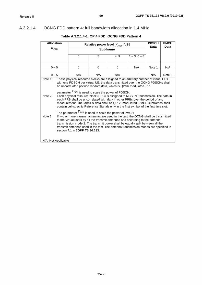
3GPP
90Release 8 3GPP TS 36.133 V8.9.0 (2010-03)
A.3.2.1.4 OCNG FDD pattern 4: full bandwidth allocation in 1.4 MHz
Table A.3.2.1.4-1: OP.4 FDD: OCNG FDD Pattern 4
Allocation
PRBn Relative power level PRBg [dB] PDSCH
Data PMCH Data
Subframe
0 5 4, 9 1 – 3, 6 – 8
0 – 5
0
0
0
N/A
Note 1
N/A
0 – 5
N/A
N/A
N/A
0
N/A
Note 2
Note 1: These physical resource blocks are assigned to an arbitrary number of virtual UEs with one PDSCH per virtual UE; the data transmitted over the OCNG PDSCHs shall be uncorrelated pseudo random data, which is QPSK modulated.The
parameter PRBg is used to scale the power of PDSCH. Note 2: Each physical resource block (PRB) is assigned to MBSFN transmission. The data in
each PRB shall be uncorrelated with data in other PRBs over the period of any measurement. The MBSFN data shall be QPSK modulated. PMCH subframes shall contain cell-specific Reference Signals only in the first symbol of the first time slot.
The parameter PRBg is used to scale the power of PMCH. Note 3: If two or more transmit antennas are used in the test, the OCNG shall be transmitted
to the virtual users by all the transmit antennas and according to the antenna transmission mode 2. The transmit power shall be equally split between all the transmit antennas used in the test. The antenna transmission modes are specified in section 7.1 in 3GPP TS 36.213.
N/A: Not Applicable
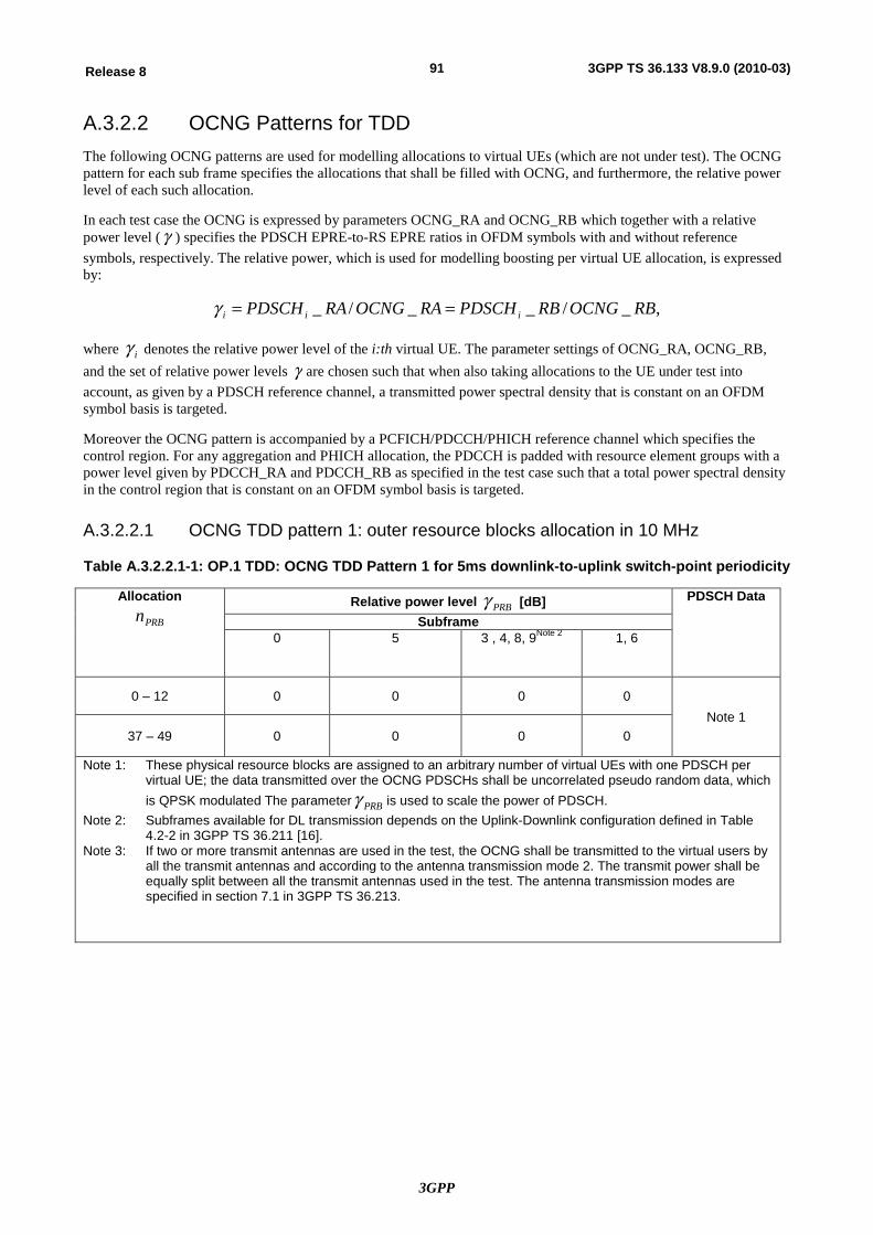
3GPP
91Release 8 3GPP TS 36.133 V8.9.0 (2010-03)
A.3.2.2 OCNG Patterns for TDD The following OCNG patterns are used for modelling allocations to virtual UEs (which are not under test). The OCNG pattern for each sub frame specifies the allocations that shall be filled with OCNG, and furthermore, the relative power level of each such allocation.
In each test case the OCNG is expressed by parameters OCNG_RA and OCNG_RB which together with a relative power level (g ) specifies the PDSCH EPRE-to-RS EPRE ratios in OFDM symbols with and without reference symbols, respectively. The relative power, which is used for modelling boosting per virtual UE allocation, is expressed by:
,_/__/_ RBOCNGRBPDSCHRAOCNGRAPDSCH iii ==g
where ig denotes the relative power level of the i:th virtual UE. The parameter settings of OCNG_RA, OCNG_RB, and the set of relative power levels g are chosen such that when also taking allocations to the UE under test into account, as given by a PDSCH reference channel, a transmitted power spectral density that is constant on an OFDM symbol basis is targeted.
Moreover the OCNG pattern is accompanied by a PCFICH/PDCCH/PHICH reference channel which specifies the control region. For any aggregation and PHICH allocation, the PDCCH is padded with resource element groups with a power level given by PDCCH_RA and PDCCH_RB as specified in the test case such that a total power spectral density in the control region that is constant on an OFDM symbol basis is targeted.
A.3.2.2.1 OCNG TDD pattern 1: outer resource blocks allocation in 10 MHz
Table A.3.2.2.1-1: OP.1 TDD: OCNG TDD Pattern 1 for 5ms downlink-to-uplink switch-point periodicity
Allocation
PRBn Relative power level PRBg [dB] PDSCH Data
Subframe
0 5 3 , 4, 8, 9Note 2 1, 6
0 – 12 0 0 0 0 Note 1
37 – 49 0 0 0 0
Note 1: These physical resource blocks are assigned to an arbitrary number of virtual UEs with one PDSCH per virtual UE; the data transmitted over the OCNG PDSCHs shall be uncorrelated pseudo random data, which is QPSK modulated The parameter PRBg is used to scale the power of PDSCH.
Note 2: Subframes available for DL transmission depends on the Uplink-Downlink configuration defined in Table 4.2-2 in 3GPP TS 36.211 [16].
Note 3: If two or more transmit antennas are used in the test, the OCNG shall be transmitted to the virtual users by all the transmit antennas and according to the antenna transmission mode 2. The transmit power shall be equally split between all the transmit antennas used in the test. The antenna transmission modes are specified in section 7.1 in 3GPP TS 36.213.
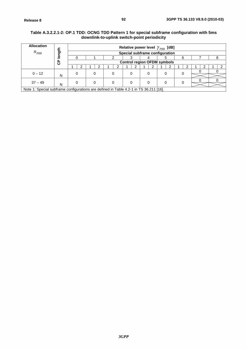
3GPP
92Release 8 3GPP TS 36.133 V8.9.0 (2010-03)
Table A.3.2.2.1-2: OP.1 TDD: OCNG TDD Pattern 1 for special subframe configuration with 5ms downlink-to-uplink switch-point periodicity
Allocation
PRBn
CP
leng
th Relative power level PRBg [dB]
Special subframe configuration 0 1 2 3 4 5 6 7 8
Control region OFDM symbols 1 2 1 2 1 2 1 2 1 2 1 2 1 2 1 2 1 2
0 – 12 N 0 0 0 0 0 0 0 0 0
37 – 49 N 0 0 0 0 0 0 0 0 0
Note 1: Special subframe configurations are defined in Table 4.2-1 in TS 36.211 [16].
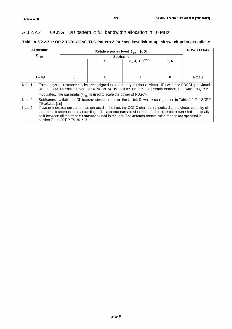
3GPP
93Release 8 3GPP TS 36.133 V8.9.0 (2010-03)
A.3.2.2.2 OCNG TDD pattern 2: full bandwidth allocation in 10 MHz
Table A.3.2.2.2-1: OP.2 TDD: OCNG TDD Pattern 2 for 5ms downlink-to-uplink switch-point periodicity
Allocation
PRBn Relative power level PRBg [dB] PDSCH Data
Subframe 0 5 3 , 4, 8, 9Note 2 1, 6
0 – 49 0 0 0 0 Note 1
Note 1: These physical resource blocks are assigned to an arbitrary number of virtual UEs with one PDSCH per virtual UE; the data transmitted over the OCNG PDSCHs shall be uncorrelated pseudo random data, which is QPSK modulated. The parameter PRBg is used to scale the power of PDSCH.
Note 2: Subframes available for DL transmission depends on the Uplink-Downlink configuration in Table 4.2-2 in 3GPP TS 36.211 [16].
Note 3: If two or more transmit antennas are used in the test, the OCNG shall be transmitted to the virtual users by all the transmit antennas and according to the antenna transmission mode 2. The transmit power shall be equally split between all the transmit antennas used in the test. The antenna transmission modes are specified in section 7.1 in 3GPP TS 36.213.
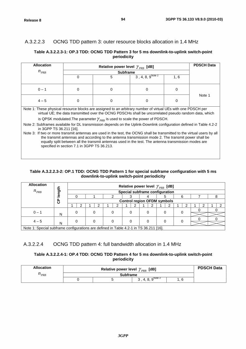
3GPP
94Release 8 3GPP TS 36.133 V8.9.0 (2010-03)
A.3.2.2.3 OCNG TDD pattern 3: outer resource blocks allocation in 1.4 MHz
Table A.3.2.2.3-1: OP.3 TDD: OCNG TDD Pattern 3 for 5 ms downlink-to-uplink switch-point periodicity
Allocation
PRBn Relative power level PRBg [dB] PDSCH Data
Subframe
0 5 3 , 4, 8, 9Note 2 1, 6
0 – 1 0 0 0 0 Note 1
4 – 5 0 0 0 0
Note 1: These physical resource blocks are assigned to an arbitrary number of virtual UEs with one PDSCH per virtual UE; the data transmitted over the OCNG PDSCHs shall be uncorrelated pseudo random data, which is QPSK modulated.The parameter PRBg is used to scale the power of PDSCH.
Note 2: Subframes available for DL transmission depends on the Uplink-Downlink configuration defined in Table 4.2-2 in 3GPP TS 36.211 [16].
Note 3: If two or more transmit antennas are used in the test, the OCNG shall be transmitted to the virtual users by all the transmit antennas and according to the antenna transmission mode 2. The transmit power shall be equally split between all the transmit antennas used in the test. The antenna transmission modes are specified in section 7.1 in 3GPP TS 36.213.
Table A.3.2.2.3-2: OP.1 TDD: OCNG TDD Pattern 1 for special subframe configuration with 5 ms downlink-to-uplink switch-point periodicity
Allocation
PRBn
CP
leng
th Relative power level PRBg [dB]
Special subframe configuration 0 1 2 3 4 5 6 7 8
Control region OFDM symbols 1 2 1 2 1 2 1 2 1 2 1 2 1 2 1 2 1 2
0 – 1 N 0 0 0 0 0 0 0 0 0
4 – 5 N 0 0 0 0 0 0 0 0 0
Note 1: Special subframe configurations are defined in Table 4.2-1 in TS 36.211 [16].
A.3.2.2.4 OCNG TDD pattern 4: full bandwidth allocation in 1.4 MHz
Table A.3.2.2.4-1: OP.4 TDD: OCNG TDD Pattern 4 for 5 ms downlink-to-uplink switch-point periodicity
Allocation
PRBn Relative power level PRBg [dB] PDSCH Data
Subframe 0 5 3 , 4, 8, 9Note 2 1, 6
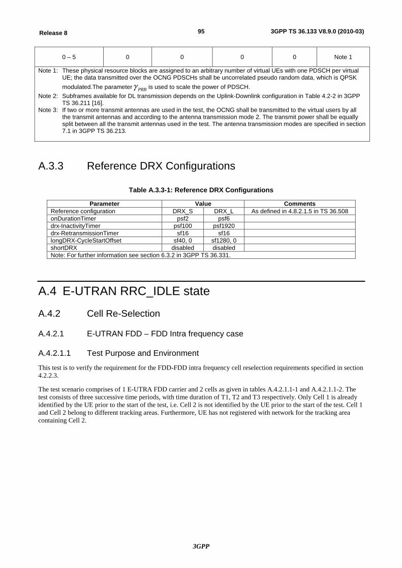
3GPP
95Release 8 3GPP TS 36.133 V8.9.0 (2010-03)
0 – 5 0 0 0 0 Note 1
Note 1: These physical resource blocks are assigned to an arbitrary number of virtual UEs with one PDSCH per virtual UE; the data transmitted over the OCNG PDSCHs shall be uncorrelated pseudo random data, which is QPSK modulated.The parameter PRBg is used to scale the power of PDSCH.
Note 2: Subframes available for DL transmission depends on the Uplink-Downlink configuration in Table 4.2-2 in 3GPP TS 36.211 [16].
Note 3: If two or more transmit antennas are used in the test, the OCNG shall be transmitted to the virtual users by all the transmit antennas and according to the antenna transmission mode 2. The transmit power shall be equally split between all the transmit antennas used in the test. The antenna transmission modes are specified in section 7.1 in 3GPP TS 36.213.
A.3.3 Reference DRX Configurations
Table A.3.3-1: Reference DRX Configurations
Parameter Value Comments Reference configuration DRX_S DRX_L As defined in 4.8.2.1.5 in TS 36.508 onDurationTimer psf2 psf6 drx-InactivityTimer psf100 psf1920 drx-RetransmissionTimer sf16 sf16 longDRX-CycleStartOffset sf40, 0 sf1280, 0 shortDRX disabled disabled Note: For further information see section 6.3.2 in 3GPP TS 36.331.
A.4 E-UTRAN RRC_IDLE state
A.4.2 Cell Re-Selection
A.4.2.1 E-UTRAN FDD – FDD Intra frequency case
A.4.2.1.1 Test Purpose and Environment
This test is to verify the requirement for the FDD-FDD intra frequency cell reselection requirements specified in section 4.2.2.3.
The test scenario comprises of 1 E-UTRA FDD carrier and 2 cells as given in tables A.4.2.1.1-1 and A.4.2.1.1-2. The test consists of three successive time periods, with time duration of T1, T2 and T3 respectively. Only Cell 1 is already identified by the UE prior to the start of the test, i.e. Cell 2 is not identified by the UE prior to the start of the test. Cell 1 and Cell 2 belong to different tracking areas. Furthermore, UE has not registered with network for the tracking area containing Cell 2.
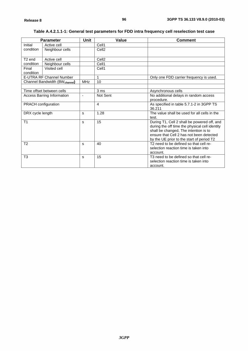
3GPP
96Release 8 3GPP TS 36.133 V8.9.0 (2010-03)
Table A.4.2.1.1-1: General test parameters for FDD intra frequency cell reselection test case
Parameter Unit Value Comment Initial condition
Active cell Cell1 Neighbour cells Cell2
T2 end condition
Active cell Cell2 Neighbour cells Cell1
Final condition
Visited cell Cell1
E-UTRA RF Channel Number 1 Only one FDD carrier frequency is used. Channel Bandwidth (BWchannel) MHz 10 Time offset between cells 3 ms Asynchronous cells Access Barring Information - Not Sent No additional delays in random access
procedure. PRACH configuration 4 As specified in table 5.7.1-2 in 3GPP TS
36.211 DRX cycle length s 1.28 The value shall be used for all cells in the
test. T1 s 15 During T1, Cell 2 shall be powered off, and
during the off time the physical cell identity shall be changed, The intention is to ensure that Cell 2 has not been detected by the UE prior to the start of period T2
T2 s 40 T2 need to be defined so that cell re-selection reaction time is taken into account.
T3 s 15 T3 need to be defined so that cell re-selection reaction time is taken into account.
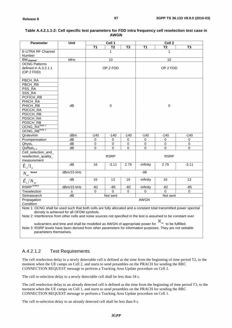
3GPP
97Release 8 3GPP TS 36.133 V8.9.0 (2010-03)
Table A.4.2.1.1-2: Cell specific test parameters for FDD intra frequency cell reselection test case in AWGN
Parameter Unit Cell 1 Cell 2 T1 T2 T3 T1 T2 T3
E-UTRA RF Channel Number
1 1
BWchannel MHz 10 10 OCNG Patterns defined in A.3.2.1.1 (OP.2 FDD)
OP.2 FDD
OP.2 FDD
PBCH_RA
dB 0 0
PBCH_RB PSS_RA SSS_RA PCFICH_RB PHICH_RA PHICH_RB PDCCH_RA PDCCH_RB PDSCH_RA PDSCH_RB OCNG_RANote 1 OCNG_RBNote 1 Qrxlevmin dBm -140 -140 -140 -140 -140 -140 Pcompensation dB 0 0 0 0 0 0 Qhysts dB 0 0 0 0 0 0 Qoffsets, n dB 0 0 0 0 0 0 Cell_selection_and_ reselection_quality_measurement
RSRP RSRP
ots IÊ dB 16 -3.11 2.79 -infinity 2.79 -3.11
ocN Note2 dBm/15 kHz -98
ocs NÊ dB 16 13 16 -infinity 16 13
RSRP Note3 dBm/15 kHz -82 -85 -82 -infinity -82 -85 Treselection s 0 0 0 0 0 0 Sintrasearch dB Not sent Not sent Propagation Condition
AWGN
Note 1: OCNG shall be used such that both cells are fully allocated and a constant total transmitted power spectral density is achieved for all OFDM symbols.
Note 2: Interference from other cells and noise sources not specified in the test is assumed to be constant over
subcarriers and time and shall be modelled as AWGN of appropriate power for ocN to be fulfilled.
Note 3: RSRP levels have been derived from other parameters for information purposes. They are not settable parameters themselves.
A.4.2.1.2 Test Requirements
The cell reselection delay to a newly detectable cell is defined as the time from the beginning of time period T2, to the moment when the UE camps on Cell 2, and starts to send preambles on the PRACH for sending the RRC CONNECTION REQUEST message to perform a Tracking Area Update procedure on Cell 2.
The cell re-selection delay to a newly detectable cell shall be less than 34 s.
The cell reselection delay to an already detected cell is defined as the time from the beginning of time period T3, to the moment when the UE camps on Cell 1, and starts to send preambles on the PRACH for sending the RRC CONNECTION REQUEST message to perform a Tracking Area Update procedure on Cell 1.
The cell re-selection delay to an already detected cell shall be less than 8 s.
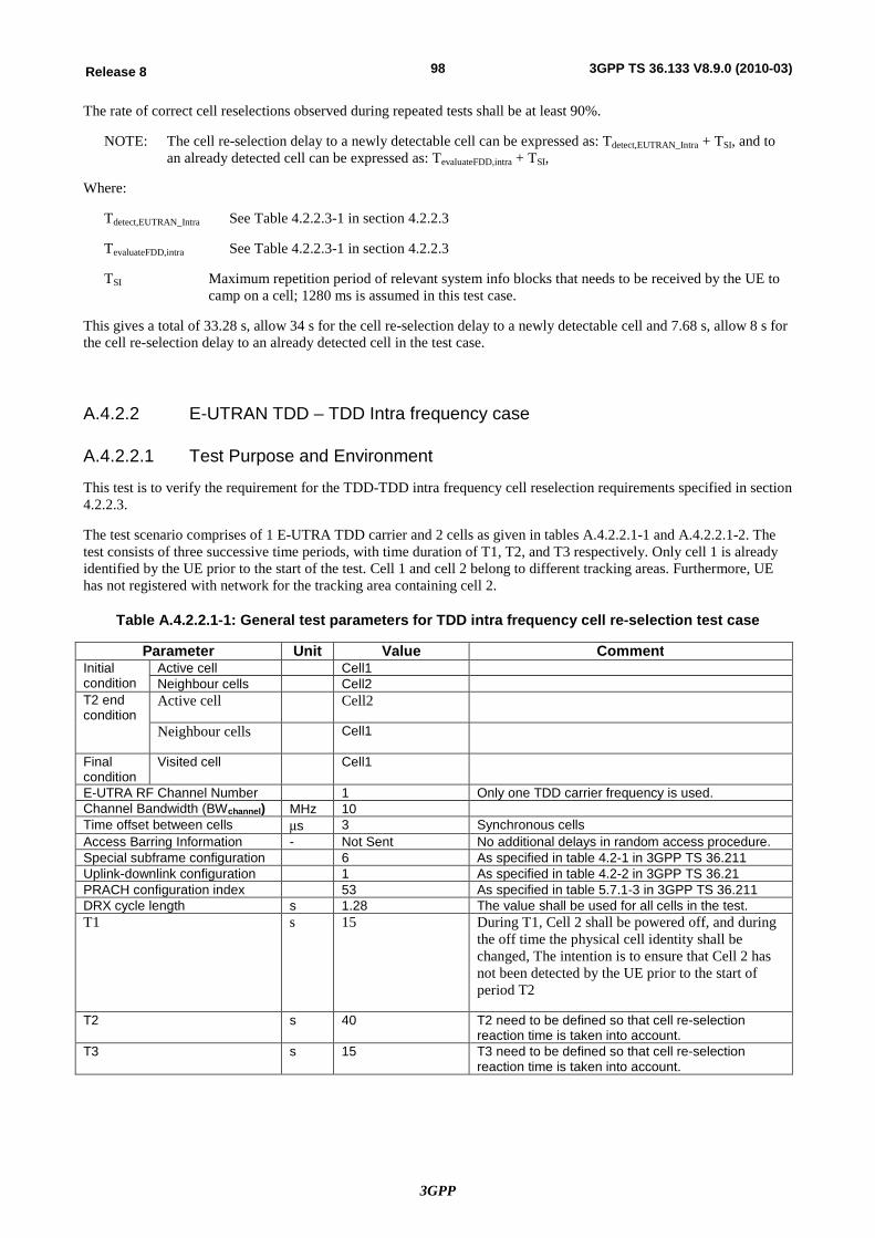
3GPP
98Release 8 3GPP TS 36.133 V8.9.0 (2010-03)
The rate of correct cell reselections observed during repeated tests shall be at least 90%.
NOTE: The cell re-selection delay to a newly detectable cell can be expressed as: Tdetect,EUTRAN_Intra + TSI, and to an already detected cell can be expressed as: TevaluateFDD,intra + TSI,
Where:
Tdetect,EUTRAN_Intra See Table 4.2.2.3-1 in section 4.2.2.3
TevaluateFDD,intra See Table 4.2.2.3-1 in section 4.2.2.3
TSI Maximum repetition period of relevant system info blocks that needs to be received by the UE to camp on a cell; 1280 ms is assumed in this test case.
This gives a total of 33.28 s, allow 34 s for the cell re-selection delay to a newly detectable cell and 7.68 s, allow 8 s for the cell re-selection delay to an already detected cell in the test case.
A.4.2.2 E-UTRAN TDD – TDD Intra frequency case
A.4.2.2.1 Test Purpose and Environment
This test is to verify the requirement for the TDD-TDD intra frequency cell reselection requirements specified in section 4.2.2.3.
The test scenario comprises of 1 E-UTRA TDD carrier and 2 cells as given in tables A.4.2.2.1-1 and A.4.2.2.1-2. The test consists of three successive time periods, with time duration of T1, T2, and T3 respectively. Only cell 1 is already identified by the UE prior to the start of the test. Cell 1 and cell 2 belong to different tracking areas. Furthermore, UE has not registered with network for the tracking area containing cell 2.
Table A.4.2.2.1-1: General test parameters for TDD intra frequency cell re-selection test case
Parameter Unit Value Comment Initial condition
Active cell Cell1 Neighbour cells Cell2
T2 end condition
Active cell Cell2
Neighbour cells Cell1
Final condition
Visited cell Cell1
E-UTRA RF Channel Number 1 Only one TDD carrier frequency is used. Channel Bandwidth (BWchannel) MHz 10 Time offset between cells ms 3 Synchronous cells Access Barring Information - Not Sent No additional delays in random access procedure. Special subframe configuration 6 As specified in table 4.2-1 in 3GPP TS 36.211 Uplink-downlink configuration 1 As specified in table 4.2-2 in 3GPP TS 36.21 PRACH configuration index 53 As specified in table 5.7.1-3 in 3GPP TS 36.211 DRX cycle length s 1.28 The value shall be used for all cells in the test. T1 s 15 During T1, Cell 2 shall be powered off, and during
the off time the physical cell identity shall be changed, The intention is to ensure that Cell 2 has not been detected by the UE prior to the start of period T2
T2 s 40 T2 need to be defined so that cell re-selection reaction time is taken into account.
T3 s 15 T3 need to be defined so that cell re-selection reaction time is taken into account.
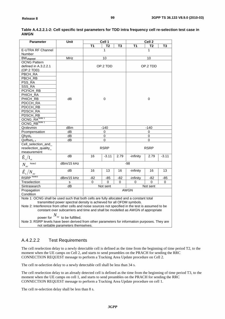
3GPP
99Release 8 3GPP TS 36.133 V8.9.0 (2010-03)
Table A.4.2.2.1-2: Cell specific test parameters for TDD intra frequency cell re-selection test case in AWGN
A.4.2.2.2 Test Requirements
The cell reselection delay to a newly detectable cell is defined as the time from the beginning of time period T2, to the moment when the UE camps on Cell 2, and starts to send preambles on the PRACH for sending the RRC CONNECTION REQUEST message to perform a Tracking Area Update procedure on Cell 2.
The cell re-selection delay to a newly detectable cell shall be less than 34 s.
The cell reselection delay to an already detected cell is defined as the time from the beginning of time period T3, to the moment when the UE camps on cell 1, and starts to send preambles on the PRACH for sending the RRC CONNECTION REQUEST message to perform a Tracking Area Update procedure on cell 1.
The cell re-selection delay shall be less than 8 s.
Parameter Unit Cell 1 Cell 2 T1 T2 T3 T1 T2 T3
E-UTRA RF Channel Number
1 1
BWchannel MHz 10 10 OCNG Pattern defined in A.3.2.2.1 (OP.2 TDD)
OP.2 TDD
OP.2 TDD
PBCH_RA
dB 0 0
PBCH_RB PSS_RA SSS_RA PCFICH_RB PHICH_RA PHICH_RB PDCCH_RA PDCCH_RB PDSCH_RA PDSCH_RB OCNG_RANote 1 OCNG_RBNote 1 Qrxlevmin dBm -140 -140 Pcompensation dB 0 0 Qhysts dB 0 0 Qoffsets, n dB 0 0 Cell_selection_and_ reselection_quality_measurement
RSRP RSRP
ots IÊ dB 16 -3.11 2.79 -infinity 2.79 -3.11
ocN Note2 dBm/15 kHz -98
ocs NÊ dB 16 13 16 -infinity 16 13
RSRP Note3 dBm/15 kHz -82 -85 -82 -infinity -82 -85 Treselection s 0 0 0 0 0 0 Sintrasearch dB Not sent Not sent Propagation Condition
AWGN
Note 1: OCNG shall be used such that both cells are fully allocated and a constant total transmitted power spectral density is achieved for all OFDM symbols.
Note 2: Interference from other cells and noise sources not specified in the test is assumed to be constant over subcarriers and time and shall be modelled as AWGN of appropriate
power for ocN to be fulfilled.
Note 3: RSRP levels have been derived from other parameters for information purposes. They are not settable parameters themselves.
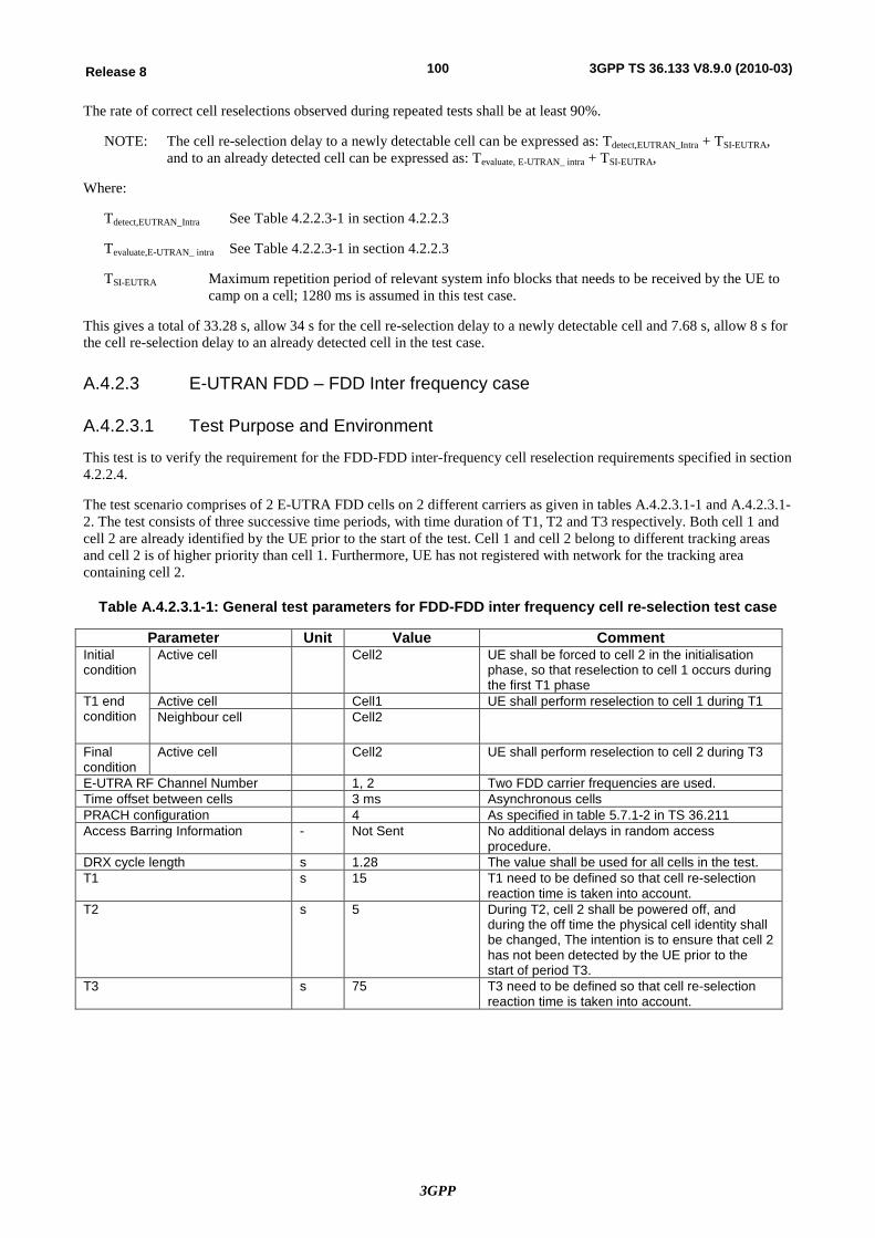
3GPP
100Release 8 3GPP TS 36.133 V8.9.0 (2010-03)
The rate of correct cell reselections observed during repeated tests shall be at least 90%.
NOTE: The cell re-selection delay to a newly detectable cell can be expressed as: Tdetect,EUTRAN_Intra + TSI-EUTRA, and to an already detected cell can be expressed as: Tevaluate, E-UTRAN_ intra + TSI-EUTRA,
Where:
Tdetect,EUTRAN_Intra See Table 4.2.2.3-1 in section 4.2.2.3
Tevaluate,E-UTRAN_ intra See Table 4.2.2.3-1 in section 4.2.2.3
TSI-EUTRA Maximum repetition period of relevant system info blocks that needs to be received by the UE to camp on a cell; 1280 ms is assumed in this test case.
This gives a total of 33.28 s, allow 34 s for the cell re-selection delay to a newly detectable cell and 7.68 s, allow 8 s for the cell re-selection delay to an already detected cell in the test case.
A.4.2.3 E-UTRAN FDD – FDD Inter frequency case
A.4.2.3.1 Test Purpose and Environment
This test is to verify the requirement for the FDD-FDD inter-frequency cell reselection requirements specified in section 4.2.2.4.
The test scenario comprises of 2 E-UTRA FDD cells on 2 different carriers as given in tables A.4.2.3.1-1 and A.4.2.3.1-2. The test consists of three successive time periods, with time duration of T1, T2 and T3 respectively. Both cell 1 and cell 2 are already identified by the UE prior to the start of the test. Cell 1 and cell 2 belong to different tracking areas and cell 2 is of higher priority than cell 1. Furthermore, UE has not registered with network for the tracking area containing cell 2.
Table A.4.2.3.1-1: General test parameters for FDD-FDD inter frequency cell re-selection test case
Parameter Unit Value Comment Initial condition
Active cell Cell2 UE shall be forced to cell 2 in the initialisation phase, so that reselection to cell 1 occurs during the first T1 phase
T1 end condition
Active cell Cell1 UE shall perform reselection to cell 1 during T1 Neighbour cell Cell2
Final condition
Active cell Cell2 UE shall perform reselection to cell 2 during T3
E-UTRA RF Channel Number 1, 2 Two FDD carrier frequencies are used. Time offset between cells 3 ms Asynchronous cells PRACH configuration 4 As specified in table 5.7.1-2 in TS 36.211 Access Barring Information - Not Sent No additional delays in random access
procedure. DRX cycle length s 1.28 The value shall be used for all cells in the test. T1 s 15 T1 need to be defined so that cell re-selection
reaction time is taken into account. T2 s 5 During T2, cell 2 shall be powered off, and
during the off time the physical cell identity shall be changed, The intention is to ensure that cell 2 has not been detected by the UE prior to the start of period T3.
T3 s 75 T3 need to be defined so that cell re-selection reaction time is taken into account.
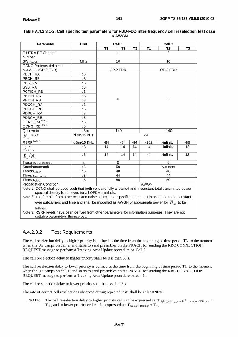
3GPP
101Release 8 3GPP TS 36.133 V8.9.0 (2010-03)
Table A.4.2.3.1-2: Cell specific test parameters for FDD-FDD inter-frequency cell reselection test case in AWGN
Parameter Unit Cell 1 Cell 2 T1 T2 T3 T1 T2 T3
E-UTRA RF Channel number
1 2
BWchannel MHz 10 10 OCNG Patterns defined in A.3.2.1.1 (OP.2 FDD)
OP.2 FDD
OP.2 FDD
PBCH_RA dB
0
0
PBCH_RB dB PSS_RA dB SSS_RA dB PCFICH_RB dB PHICH_RA dB PHICH_RB dB PDCCH_RA dB PDCCH_RB dB PDSCH_RA dB PDSCH_RB dB OCNG_RANote 1 dB OCNG_RBNote 1 dB Qrxlevmin dBm -140 -140
ocN Note 2 dBm/15 kHz -98
RSRP Note 3 dBm/15 KHz -84 -84 -84 -102 -infinity -86
ots IÊ dB 14 14 14 -4 -infinity 12
ocs NÊ dB 14 14 14 -4 -infinity 12
TreselectionEUTRAN s 0 0 Snonintrasearch dB 50 Not sent Threshx, high dB 48 48 Threshserving, low dB 44 44 Threshx, low dB 50 50 Propagation Condition AWGN Note 1: OCNG shall be used such that both cells are fully allocated and a constant total transmitted power
spectral density is achieved for all OFDM symbols. Note 2: Interference from other cells and noise sources not specified in the test is assumed to be constant
over subcarriers and time and shall be modelled as AWGN of appropriate power for ocN to be fulfilled.
Note 3: RSRP levels have been derived from other parameters for information purposes. They are not settable parameters themselves.
A.4.2.3.2 Test Requirements
The cell reselection delay to higher priority is defined as the time from the beginning of time period T3, to the moment when the UE camps on cell 2, and starts to send preambles on the PRACH for sending the RRC CONNECTION REQUEST message to perform a Tracking Area Update procedure on Cell 2.
The cell re-selection delay to higher priority shall be less than 68 s.
The cell reselection delay to lower priority is defined as the time from the beginning of time period T1, to the moment when the UE camps on cell 1, and starts to send preambles on the PRACH for sending the RRC CONNECTION REQUEST message to perform a Tracking Area Update procedure on cell 1.
The cell re-selection delay to lower priority shall be less than 8 s.
The rate of correct cell reselections observed during repeated tests shall be at least 90%.
NOTE: The cell re-selection delay to higher priority cell can be expressed as: Thigher_priority_search + TevaluateFDD,intra + TSI , and to lower priority cell can be expressed as: TevaluateFDD,intra + TSI,
3GPP
102Release 8 3GPP TS 36.133 V8.9.0 (2010-03)
Where:
Thigher_priority_search See section 4.2.2
TevaluateFDD,inter See Table 4.2.2.4-1 in section 4.2.2.4
TSI Maximum repetition period of relevant system info blocks that needs to be received by the UE to camp on a cell; 1280 ms is assumed in this test case.
This gives a total of 67.68 s for higher priority cell search and 7.68 s for lower priority cell search, allow 68 s for higher priority cell and 8 s for lower priority cell in the test case.
A.4.2.4 E-UTRAN FDD – TDD Inter frequency case
A.4.2.5 E-UTRAN TDD – FDD Inter frequency case
A.4.2.6 E-UTRAN TDD – TDD: Inter frequency case
A.4.2.6.1 Test Purpose and Environment
This test is to verify the requirement for the TDD-TDD inter-frequency cell reselection requirements specified in section 4.2.2.4.
The test scenario comprises of 2 E-UTRA TDD cells on 2 different carriers as given in tables A.4.2.6.1-1 and A.4.2.6.1-2. The test consists of three successive time periods, with time duration of T1, T2, and T3 respectively. Both cell 1 and cell 2 are already identified by the UE prior to the start of the test. Cell 1 and cell 2 belong to different tracking areas and cell 2 is of higher priority than cell 1. Furthermore, UE has not registered with network for the tracking area containing cell 2.
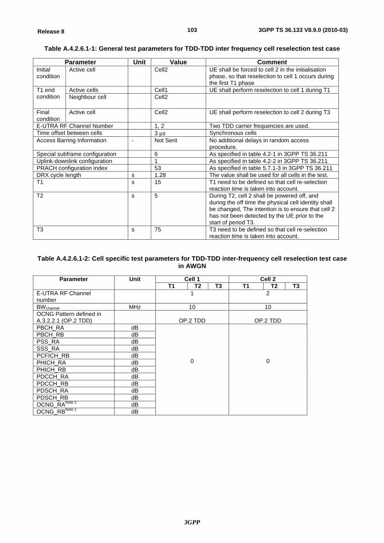
3GPP
103Release 8 3GPP TS 36.133 V8.9.0 (2010-03)
Table A.4.2.6.1-1: General test parameters for TDD-TDD inter frequency cell reselection test case
Parameter Unit Value Comment Initial condition
Active cell Cell2 UE shall be forced to cell 2 in the initialisation phase, so that reselection to cell 1 occurs during the first T1 phase
T1 end condition
Active cells Cell1 UE shall perform reselection to cell 1 during T1 Neighbour cell Cell2
Final condition
Active cell Cell2 UE shall perform reselection to cell 2 during T3
E-UTRA RF Channel Number 1, 2 Two TDD carrier frequencies are used. Time offset between cells 3 ms Synchronous cells Access Barring Information - Not Sent No additional delays in random access
procedure. Special subframe configuration 6 As specified in table 4.2-1 in 3GPP TS 36.211 Uplink-downlink configuration 1 As specified in table 4.2-2 in 3GPP TS 36.211 PRACH configuration index 53 As specified in table 5.7.1-3 in 3GPP TS 36.211 DRX cycle length s 1.28 The value shall be used for all cells in the test. T1 s 15 T1 need to be defined so that cell re-selection
reaction time is taken into account. T2 s 5 During T2, cell 2 shall be powered off, and
during the off time the physical cell identity shall be changed, The intention is to ensure that cell 2 has not been detected by the UE prior to the start of period T3.
T3 s 75 T3 need to be defined so that cell re-selection reaction time is taken into account.
Table A.4.2.6.1-2: Cell specific test parameters for TDD-TDD inter-frequency cell reselection test case in AWGN
Parameter Unit Cell 1 Cell 2 T1 T2 T3 T1 T2 T3
E-UTRA RF Channel number
1 2
BWchannel MHz 10 10 OCNG Pattern defined in A.3.2.2.1 (OP.2 TDD)
OP.2 TDD
OP.2 TDD
PBCH_RA dB
0
0
PBCH_RB dB PSS_RA dB SSS_RA dB PCFICH_RB dB PHICH_RA dB PHICH_RB dB PDCCH_RA dB PDCCH_RB dB PDSCH_RA dB PDSCH_RB dB OCNG_RANote 1 dB OCNG_RBNote 1 dB
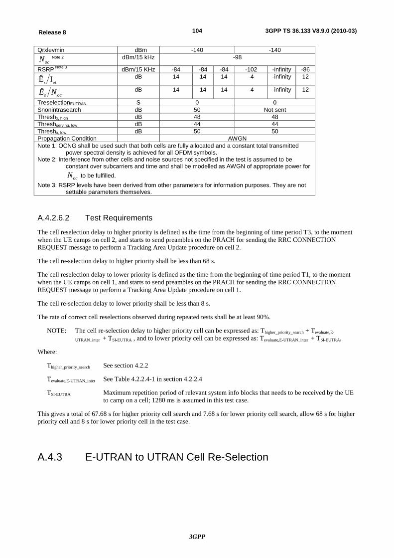
3GPP
104Release 8 3GPP TS 36.133 V8.9.0 (2010-03)
Qrxlevmin dBm -140 -140
ocN Note 2 dBm/15 kHz -98
RSRP Note 3 dBm/15 KHz -84 -84 -84 -102 -infinity -86
ots IÊ dB 14 14 14 -4 -infinity 12
ocs NÊ dB 14 14 14 -4 -infinity 12
TreselectionEUTRAN S 0 0 Snonintrasearch dB 50 Not sent Threshx, high dB 48 48 Threshserving, low dB 44 44 Threshx, low dB 50 50 Propagation Condition AWGN Note 1: OCNG shall be used such that both cells are fully allocated and a constant total transmitted
power spectral density is achieved for all OFDM symbols. Note 2: Interference from other cells and noise sources not specified in the test is assumed to be
constant over subcarriers and time and shall be modelled as AWGN of appropriate power for
ocN to be fulfilled. Note 3: RSRP levels have been derived from other parameters for information purposes. They are not
settable parameters themselves.
A.4.2.6.2 Test Requirements
The cell reselection delay to higher priority is defined as the time from the beginning of time period T3, to the moment when the UE camps on cell 2, and starts to send preambles on the PRACH for sending the RRC CONNECTION REQUEST message to perform a Tracking Area Update procedure on cell 2.
The cell re-selection delay to higher priority shall be less than 68 s.
The cell reselection delay to lower priority is defined as the time from the beginning of time period T1, to the moment when the UE camps on cell 1, and starts to send preambles on the PRACH for sending the RRC CONNECTION REQUEST message to perform a Tracking Area Update procedure on cell 1.
The cell re-selection delay to lower priority shall be less than 8 s.
The rate of correct cell reselections observed during repeated tests shall be at least 90%.
NOTE: The cell re-selection delay to higher priority cell can be expressed as: Thigher_priority_search + Tevaluate,E-
UTRAN_inter + TSI-EUTRA , and to lower priority cell can be expressed as: Tevaluate,E-UTRAN_inter + TSI-EUTRA,
Where:
Thigher_priority_search See section 4.2.2
Tevaluate,E-UTRAN_inter See Table 4.2.2.4-1 in section 4.2.2.4
TSI-EUTRA Maximum repetition period of relevant system info blocks that needs to be received by the UE to camp on a cell; 1280 ms is assumed in this test case.
This gives a total of 67.68 s for higher priority cell search and 7.68 s for lower priority cell search, allow 68 s for higher priority cell and 8 s for lower priority cell in the test case.
A.4.3 E-UTRAN to UTRAN Cell Re-Selection
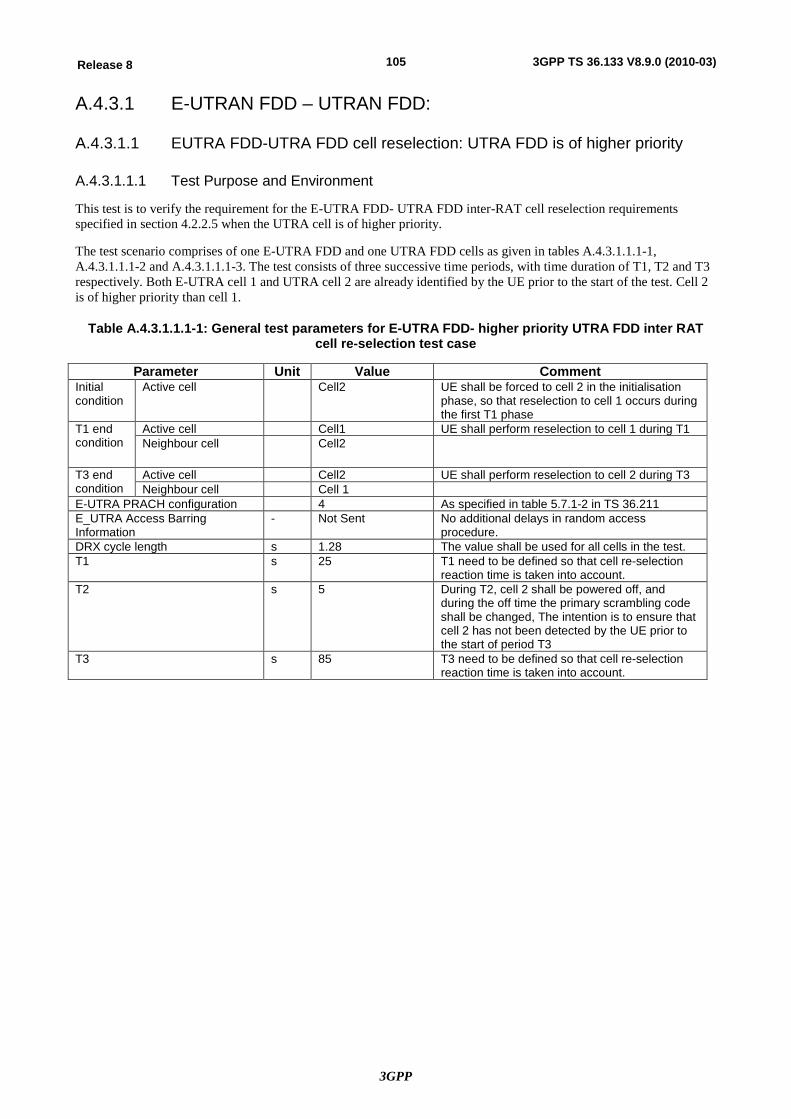
3GPP
105Release 8 3GPP TS 36.133 V8.9.0 (2010-03)
A.4.3.1 E-UTRAN FDD – UTRAN FDD:
A.4.3.1.1 EUTRA FDD-UTRA FDD cell reselection: UTRA FDD is of higher priority
A.4.3.1.1.1 Test Purpose and Environment
This test is to verify the requirement for the E-UTRA FDD- UTRA FDD inter-RAT cell reselection requirements specified in section 4.2.2.5 when the UTRA cell is of higher priority.
The test scenario comprises of one E-UTRA FDD and one UTRA FDD cells as given in tables A.4.3.1.1.1-1, A.4.3.1.1.1-2 and A.4.3.1.1.1-3. The test consists of three successive time periods, with time duration of T1, T2 and T3 respectively. Both E-UTRA cell 1 and UTRA cell 2 are already identified by the UE prior to the start of the test. Cell 2 is of higher priority than cell 1.
Table A.4.3.1.1.1-1: General test parameters for E-UTRA FDD- higher priority UTRA FDD inter RAT cell re-selection test case
Parameter Unit Value Comment Initial condition
Active cell Cell2 UE shall be forced to cell 2 in the initialisation phase, so that reselection to cell 1 occurs during the first T1 phase
T1 end condition
Active cell Cell1 UE shall perform reselection to cell 1 during T1 Neighbour cell Cell2
T3 end condition
Active cell Cell2 UE shall perform reselection to cell 2 during T3 Neighbour cell Cell 1
E-UTRA PRACH configuration 4 As specified in table 5.7.1-2 in TS 36.211 E_UTRA Access Barring Information
- Not Sent No additional delays in random access procedure.
DRX cycle length s 1.28 The value shall be used for all cells in the test. T1 s 25 T1 need to be defined so that cell re-selection
reaction time is taken into account. T2 s 5 During T2, cell 2 shall be powered off, and
during the off time the primary scrambling code shall be changed, The intention is to ensure that cell 2 has not been detected by the UE prior to the start of period T3
T3 s 85 T3 need to be defined so that cell re-selection reaction time is taken into account.
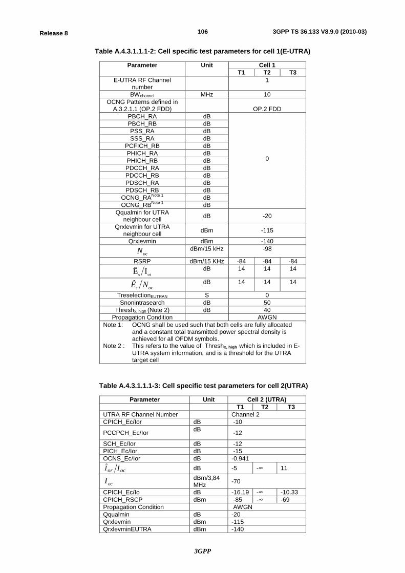
3GPP
106Release 8 3GPP TS 36.133 V8.9.0 (2010-03)
Table A.4.3.1.1.1-2: Cell specific test parameters for cell 1(E-UTRA)
Parameter Unit Cell 1 T1 T2 T3
E-UTRA RF Channel number
1
BWchannel MHz 10 OCNG Patterns defined in
A.3.2.1.1 (OP.2 FDD)
OP.2 FDD PBCH_RA dB
0
PBCH_RB dB PSS_RA dB SSS_RA dB
PCFICH_RB dB PHICH_RA dB PHICH_RB dB PDCCH_RA dB PDCCH_RB dB PDSCH_RA dB PDSCH_RB dB
OCNG_RANote 1 dB OCNG_RBNote 1 dB
Qqualmin for UTRA neighbour cell dB -20
Qrxlevmin for UTRA neighbour cell dBm -115
Qrxlevmin dBm -140
ocN dBm/15 kHz -98
RSRP dBm/15 KHz -84 -84 -84
ots IÊ dB 14 14 14
ocs NÊ dB 14 14 14
TreselectionEUTRAN S 0 Snonintrasearch dB 50
Threshx, high (Note 2) dB 40 Propagation Condition AWGN
Note 1: OCNG shall be used such that both cells are fully allocated and a constant total transmitted power spectral density is achieved for all OFDM symbols.
Note 2 : This refers to the value of Threshx, high which is included in E-UTRA system information, and is a threshold for the UTRA target cell
Table A.4.3.1.1.1-3: Cell specific test parameters for cell 2(UTRA)
Parameter Unit Cell 2 (UTRA) T1 T2 T3
UTRA RF Channel Number Channel 2 CPICH_Ec/Ior dB -10
PCCPCH_Ec/Ior dB -12
SCH_Ec/Ior dB -12 PICH_Ec/Ior dB -15 OCNS_Ec/Ior dB -0.941
ocor II dB -5 -∞ 11
ocI dBm/3,84 MHz -70
CPICH_Ec/Io dB -16.19 -∞ -10.33 CPICH_RSCP dBm -85 -∞ -69 Propagation Condition AWGN Qqualmin dB -20 Qrxlevmin dBm -115 QrxlevminEUTRA dBm -140
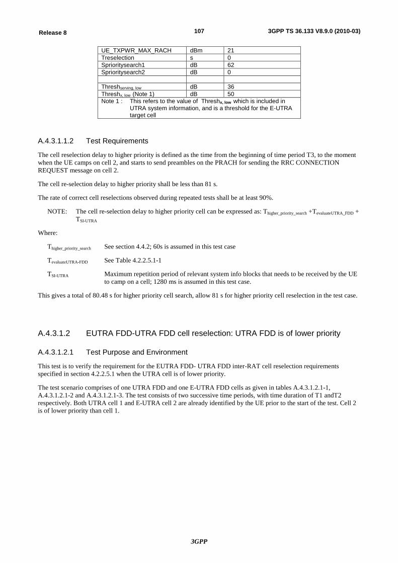
3GPP
107Release 8 3GPP TS 36.133 V8.9.0 (2010-03)
UE_TXPWR_MAX_RACH dBm 21 Treselection s 0 Sprioritysearch1 dB 62 Sprioritysearch2 dB 0 Threshserving, low dB 36 Threshx, low (Note 1) dB 50 Note 1 : This refers to the value of Threshx, low which is included in
UTRA system information, and is a threshold for the E-UTRA target cell
A.4.3.1.1.2 Test Requirements
The cell reselection delay to higher priority is defined as the time from the beginning of time period T3, to the moment when the UE camps on cell 2, and starts to send preambles on the PRACH for sending the RRC CONNECTION REQUEST message on cell 2.
The cell re-selection delay to higher priority shall be less than 81 s.
The rate of correct cell reselections observed during repeated tests shall be at least 90%.
NOTE: The cell re-selection delay to higher priority cell can be expressed as: Thigher_priority_search +TevaluateUTRA_FDD + TSI-UTRA
Where:
Thigher_priority_search See section 4.4.2; 60s is assumed in this test case
TevaluateUTRA-FDD See Table 4.2.2.5.1-1
TSI-UTRA Maximum repetition period of relevant system info blocks that needs to be received by the UE to camp on a cell; 1280 ms is assumed in this test case.
This gives a total of 80.48 s for higher priority cell search, allow 81 s for higher priority cell reselection in the test case.
A.4.3.1.2 EUTRA FDD-UTRA FDD cell reselection: UTRA FDD is of lower priority
A.4.3.1.2.1 Test Purpose and Environment
This test is to verify the requirement for the EUTRA FDD- UTRA FDD inter-RAT cell reselection requirements specified in section 4.2.2.5.1 when the UTRA cell is of lower priority.
The test scenario comprises of one UTRA FDD and one E-UTRA FDD cells as given in tables A.4.3.1.2.1-1, A.4.3.1.2.1-2 and A.4.3.1.2.1-3. The test consists of two successive time periods, with time duration of T1 andT2 respectively. Both UTRA cell 1 and E-UTRA cell 2 are already identified by the UE prior to the start of the test. Cell 2 is of lower priority than cell 1.
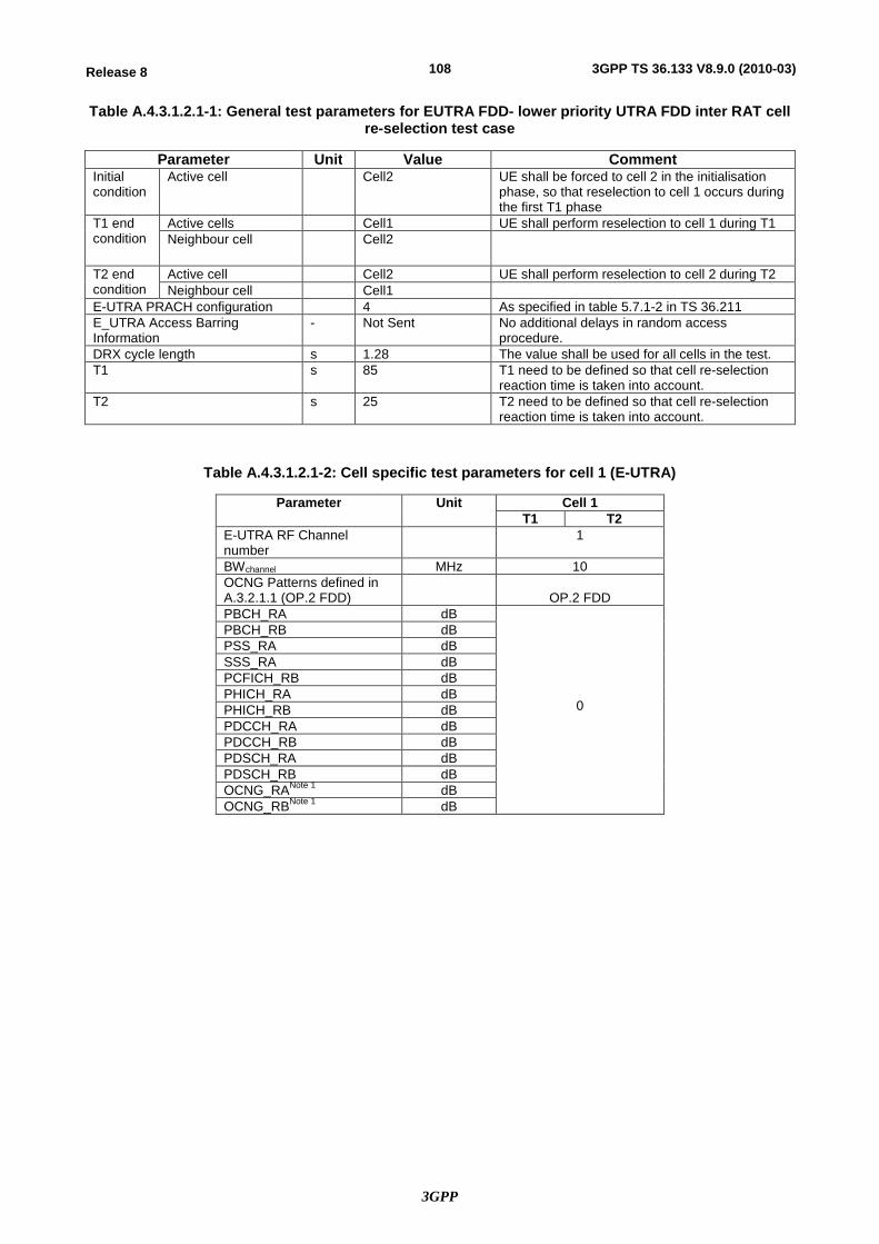
3GPP
108Release 8 3GPP TS 36.133 V8.9.0 (2010-03)
Table A.4.3.1.2.1-1: General test parameters for EUTRA FDD- lower priority UTRA FDD inter RAT cell re-selection test case
Parameter Unit Value Comment Initial condition
Active cell Cell2 UE shall be forced to cell 2 in the initialisation phase, so that reselection to cell 1 occurs during the first T1 phase
T1 end condition
Active cells Cell1 UE shall perform reselection to cell 1 during T1 Neighbour cell Cell2
T2 end condition
Active cell Cell2 UE shall perform reselection to cell 2 during T2 Neighbour cell Cell1
E-UTRA PRACH configuration 4 As specified in table 5.7.1-2 in TS 36.211 E_UTRA Access Barring Information
- Not Sent No additional delays in random access procedure.
DRX cycle length s 1.28 The value shall be used for all cells in the test. T1 s 85 T1 need to be defined so that cell re-selection
reaction time is taken into account. T2 s 25 T2 need to be defined so that cell re-selection
reaction time is taken into account.
Table A.4.3.1.2.1-2: Cell specific test parameters for cell 1 (E-UTRA)
Parameter Unit Cell 1 T1 T2
E-UTRA RF Channel number
1
BWchannel MHz 10 OCNG Patterns defined in A.3.2.1.1 (OP.2 FDD)
OP.2 FDD
PBCH_RA dB
0
PBCH_RB dB PSS_RA dB SSS_RA dB PCFICH_RB dB PHICH_RA dB PHICH_RB dB PDCCH_RA dB PDCCH_RB dB PDSCH_RA dB PDSCH_RB dB OCNG_RANote 1 dB OCNG_RBNote 1 dB
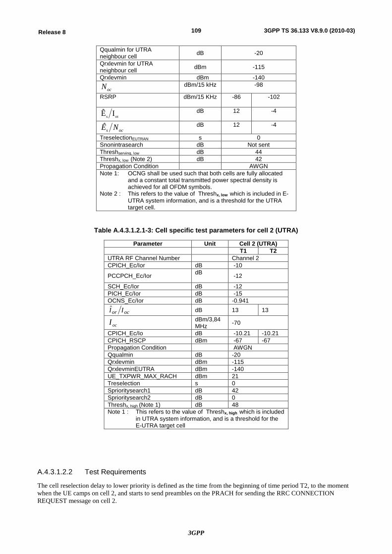
3GPP
109Release 8 3GPP TS 36.133 V8.9.0 (2010-03)
Qqualmin for UTRA neighbour cell dB -20
Qrxlevmin for UTRA neighbour cell dBm -115
Qrxlevmin dBm -140
ocN dBm/15 kHz -98
RSRP dBm/15 KHz -86 -102
ots IÊ dB 12 -4
ocs NÊ dB 12 -4
TreselectionEUTRAN s 0 Snonintrasearch dB Not sent Threshserving, low dB 44 Threshx, low (Note 2) dB 42 Propagation Condition AWGN Note 1: OCNG shall be used such that both cells are fully allocated
and a constant total transmitted power spectral density is achieved for all OFDM symbols.
Note 2 : This refers to the value of Threshx, low which is included in E-UTRA system information, and is a threshold for the UTRA target cell.
Table A.4.3.1.2.1-3: Cell specific test parameters for cell 2 (UTRA)
Parameter Unit Cell 2 (UTRA) T1 T2
UTRA RF Channel Number Channel 2 CPICH_Ec/Ior dB -10
PCCPCH_Ec/Ior dB -12
SCH_Ec/Ior dB -12 PICH_Ec/Ior dB -15 OCNS_Ec/Ior dB -0.941
ocor II dB 13 13
ocI dBm/3,84 MHz -70
CPICH_Ec/Io dB -10.21 -10.21 CPICH_RSCP dBm -67 -67 Propagation Condition AWGN Qqualmin dB -20 Qrxlevmin dBm -115 QrxlevminEUTRA dBm -140 UE_TXPWR_MAX_RACH dBm 21 Treselection s 0 Sprioritysearch1 dB 42 Sprioritysearch2 dB 0 Threshx, high (Note 1) dB 48 Note 1 : This refers to the value of Threshx, high which is included
in UTRA system information, and is a threshold for the E-UTRA target cell
A.4.3.1.2.2 Test Requirements
The cell reselection delay to lower priority is defined as the time from the beginning of time period T2, to the moment when the UE camps on cell 2, and starts to send preambles on the PRACH for sending the RRC CONNECTION REQUEST message on cell 2.
3GPP
110Release 8 3GPP TS 36.133 V8.9.0 (2010-03)
The cell re-selection delay to lower priority shall be less than 21 s.
The rate of correct cell reselections observed during repeated tests shall be at least 90%.
NOTE: The cell re-selection delay to lower priority cell can be expressed as: TevaluateUTRA_FDD + TSI-UTRA
Where:
TevaluateUTRA-FDD See Table 4.2.2.5.1-1
TSI-UTRA Maximum repetition period of relevant system info blocks that needs to be received by the UE to camp on a cell; 1280 ms is assumed in this test case.
This gives a total of 20.48 s for lower priority cell reselection, allow 21 s.
A.4.3.1.3 EUTRA FDD-UTRA FDD cell reselection in fading propagation conditions: UTRA FDD is of lower priority
A.4.3.1.3.1 Test Purpose and Environment
This test is to verify the requirement for the EUTRA FDD- UTRA FDD inter-RAT cell reselection requirements specified in section 4.2.2.5.1 when the UTRA cell is of lower priority, and to verify the robustness of the UE measurement filtering in a fading environment. The E-UTRA cell is in fading propagation conditions and the UTRA cell is in AWGN propagation conditions.
The test scenario comprises of one UTRA FDD and one E-UTRA FDD cells as given in tables A.4.3.1.3.1-1, A.4.3.1.3.1-2 and A.4.3.1.3.1-3. The test consists of four successive time periods, with time duration of T1 T2, T3 and T4 respectively. Both UTRA cell 1 and E-UTRA cell 2 are already identified by the UE prior to the start of the test. Cell 2 is of lower priority than cell 1.
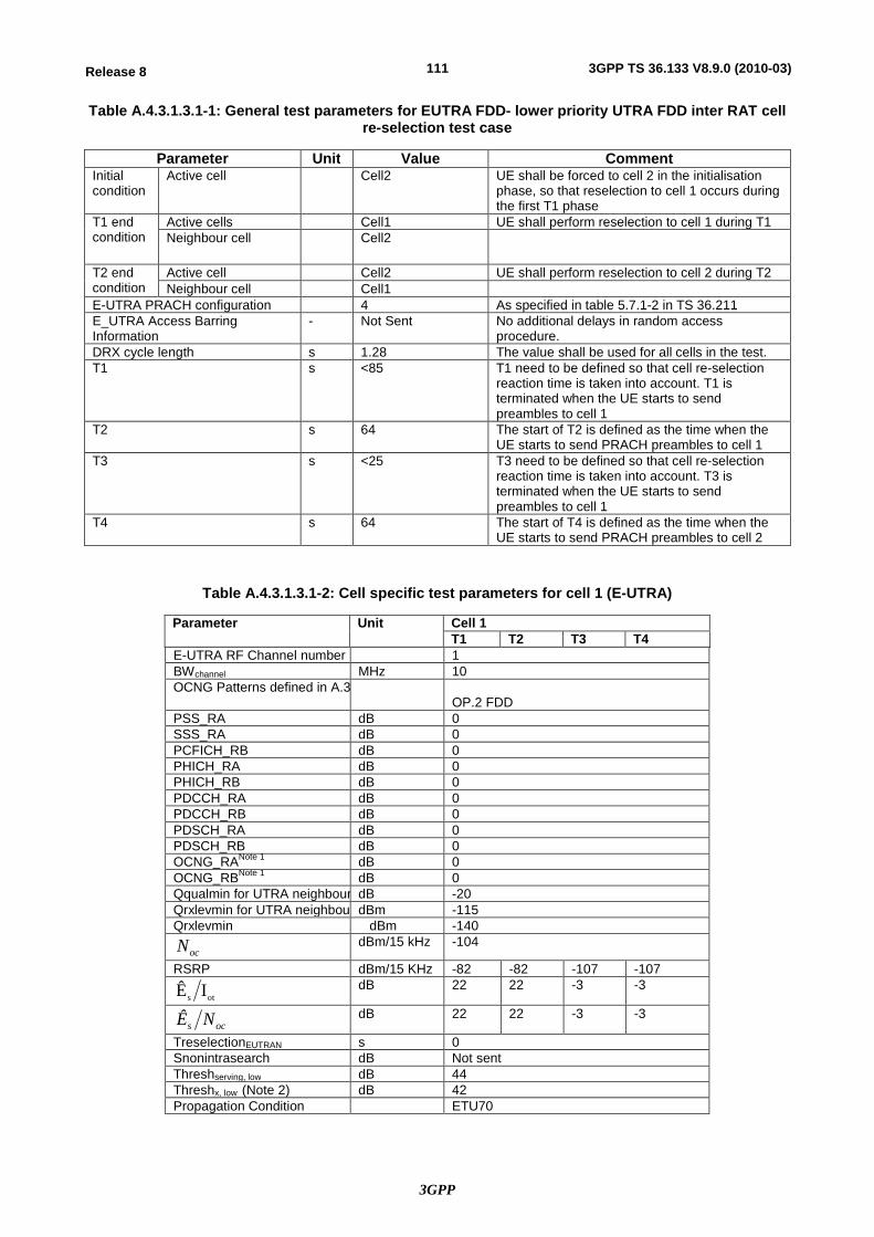
3GPP
111Release 8 3GPP TS 36.133 V8.9.0 (2010-03)
Table A.4.3.1.3.1-1: General test parameters for EUTRA FDD- lower priority UTRA FDD inter RAT cell re-selection test case
Parameter Unit Value Comment Initial condition
Active cell Cell2 UE shall be forced to cell 2 in the initialisation phase, so that reselection to cell 1 occurs during the first T1 phase
T1 end condition
Active cells Cell1 UE shall perform reselection to cell 1 during T1 Neighbour cell Cell2
T2 end condition
Active cell Cell2 UE shall perform reselection to cell 2 during T2 Neighbour cell Cell1
E-UTRA PRACH configuration 4 As specified in table 5.7.1-2 in TS 36.211 E_UTRA Access Barring Information
- Not Sent No additional delays in random access procedure.
DRX cycle length s 1.28 The value shall be used for all cells in the test. T1 s <85 T1 need to be defined so that cell re-selection
reaction time is taken into account. T1 is terminated when the UE starts to send preambles to cell 1
T2 s 64 The start of T2 is defined as the time when the UE starts to send PRACH preambles to cell 1
T3 s <25 T3 need to be defined so that cell re-selection reaction time is taken into account. T3 is terminated when the UE starts to send preambles to cell 1
T4 s 64 The start of T4 is defined as the time when the UE starts to send PRACH preambles to cell 2
Table A.4.3.1.3.1-2: Cell specific test parameters for cell 1 (E-UTRA)
Parameter Unit Cell 1 T1 T2 T3 T4
E-UTRA RF Channel number 1 BWchannel MHz 10 OCNG Patterns defined in A.3.
OP.2 FDD PSS_RA dB 0 SSS_RA dB 0 PCFICH_RB dB 0 PHICH_RA dB 0 PHICH_RB dB 0 PDCCH_RA dB 0 PDCCH_RB dB 0 PDSCH_RA dB 0 PDSCH_RB dB 0 OCNG_RANote 1 dB 0 OCNG_RBNote 1 dB 0 Qqualmin for UTRA neighbour celldB -20 Qrxlevmin for UTRA neighbour celldBm -115 Qrxlevmin dBm -140
ocN dBm/15 kHz -104
RSRP dBm/15 KHz -82 -82 -107 -107
ots IÊ dB 22 22 -3 -3
ocs NÊ dB 22 22 -3 -3
TreselectionEUTRAN s 0 Snonintrasearch dB Not sent Threshserving, low dB 44 Threshx, low (Note 2) dB 42 Propagation Condition ETU70
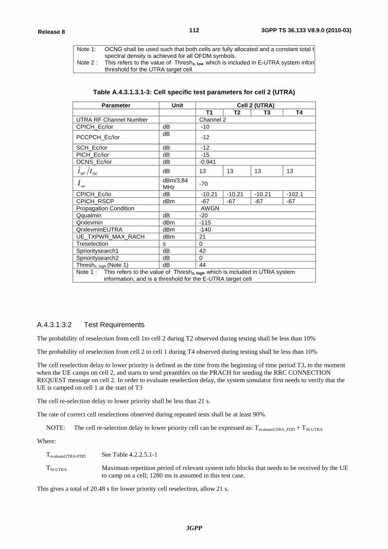
3GPP
112Release 8 3GPP TS 36.133 V8.9.0 (2010-03)
Note 1: OCNG shall be used such that both cells are fully allocated and a constant total transmitted power spectral density is achieved for all OFDM symbols.
Note 2 : This refers to the value of Threshx, low which is included in E-UTRA system information, and is a threshold for the UTRA target cell.
Table A.4.3.1.3.1-3: Cell specific test parameters for cell 2 (UTRA)
Parameter Unit Cell 2 (UTRA) T1 T2 T3 T4
UTRA RF Channel Number Channel 2 CPICH_Ec/Ior dB -10
PCCPCH_Ec/Ior dB -12
SCH_Ec/Ior dB -12 PICH_Ec/Ior dB -15 OCNS_Ec/Ior dB -0.941
ocor II dB 13 13 13 13
ocI dBm/3,84 MHz -70
CPICH_Ec/Io dB -10.21 -10.21 -10.21 -102.1 CPICH_RSCP dBm -67 -67 -67 -67 Propagation Condition AWGN Qqualmin dB -20 Qrxlevmin dBm -115 QrxlevminEUTRA dBm -140 UE_TXPWR_MAX_RACH dBm 21 Treselection s 0 Sprioritysearch1 dB 42 Sprioritysearch2 dB 0 Threshx, high (Note 1) dB 44 Note 1 : This refers to the value of Threshx, high which is included in UTRA system
information, and is a threshold for the E-UTRA target cell
A.4.3.1.3.2 Test Requirements
The probability of reselection from cell 1to cell 2 during T2 observed during testing shall be less than 10%
The probability of reselection from cell 2 to cell 1 during T4 observed during testing shall be less than 10%
The cell reselection delay to lower priority is defined as the time from the beginning of time period T3, to the moment when the UE camps on cell 2, and starts to send preambles on the PRACH for sending the RRC CONNECTION REQUEST message on cell 2. In order to evaluate reselection delay, the system simulator first needs to verify that the UE is camped on cell 1 at the start of T3
The cell re-selection delay to lower priority shall be less than 21 s.
The rate of correct cell reselections observed during repeated tests shall be at least 90%.
NOTE: The cell re-selection delay to lower priority cell can be expressed as: TevaluateUTRA_FDD + TSI-UTRA
Where:
TevaluateUTRA-FDD See Table 4.2.2.5.1-1
TSI-UTRA Maximum repetition period of relevant system info blocks that needs to be received by the UE to camp on a cell; 1280 ms is assumed in this test case.
This gives a total of 20.48 s for lower priority cell reselection, allow 21 s.
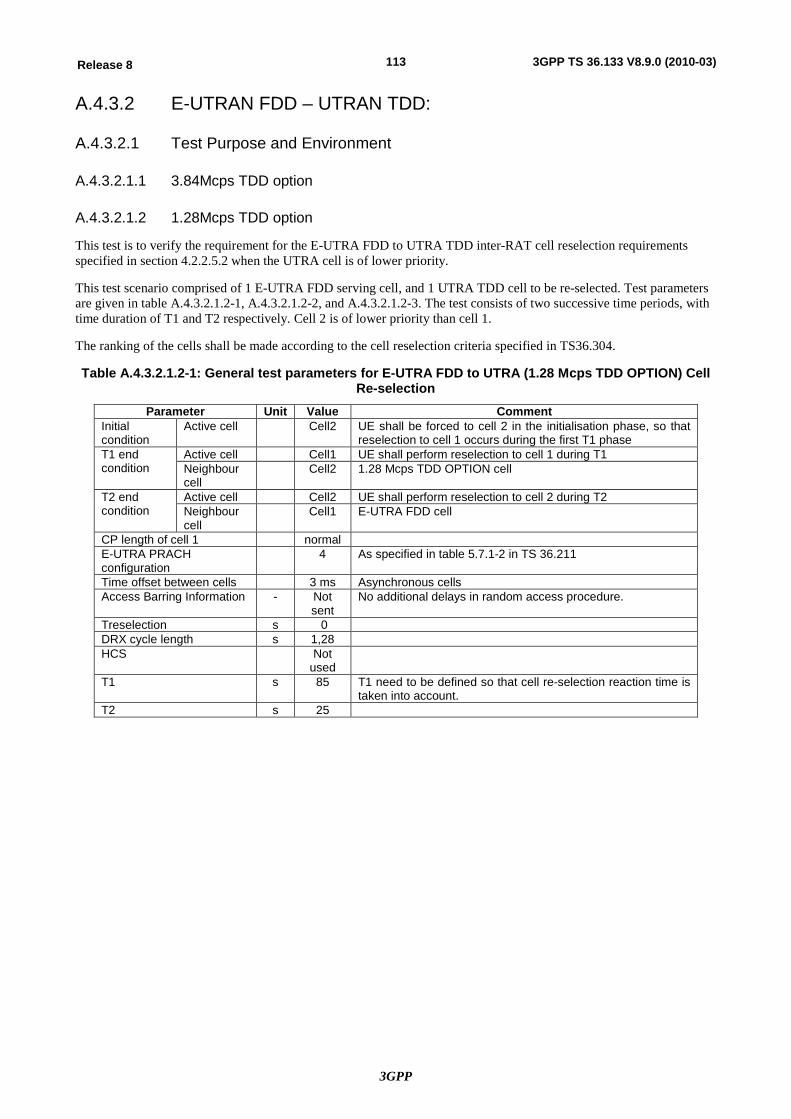
3GPP
113Release 8 3GPP TS 36.133 V8.9.0 (2010-03)
A.4.3.2 E-UTRAN FDD – UTRAN TDD:
A.4.3.2.1 Test Purpose and Environment
A.4.3.2.1.1 3.84Mcps TDD option
A.4.3.2.1.2 1.28Mcps TDD option
This test is to verify the requirement for the E-UTRA FDD to UTRA TDD inter-RAT cell reselection requirements specified in section 4.2.2.5.2 when the UTRA cell is of lower priority.
This test scenario comprised of 1 E-UTRA FDD serving cell, and 1 UTRA TDD cell to be re-selected. Test parameters are given in table A.4.3.2.1.2-1, A.4.3.2.1.2-2, and A.4.3.2.1.2-3. The test consists of two successive time periods, with time duration of T1 and T2 respectively. Cell 2 is of lower priority than cell 1.
The ranking of the cells shall be made according to the cell reselection criteria specified in TS36.304.
Table A.4.3.2.1.2-1: General test parameters for E-UTRA FDD to UTRA (1.28 Mcps TDD OPTION) Cell Re-selection
Parameter Unit Value Comment Initial condition
Active cell Cell2 UE shall be forced to cell 2 in the initialisation phase, so that reselection to cell 1 occurs during the first T1 phase
T1 end condition
Active cell Cell1 UE shall perform reselection to cell 1 during T1 Neighbour cell
Cell2 1.28 Mcps TDD OPTION cell
T2 end condition
Active cell Cell2 UE shall perform reselection to cell 2 during T2 Neighbour cell
Cell1 E-UTRA FDD cell
CP length of cell 1 normal E-UTRA PRACH configuration
4 As specified in table 5.7.1-2 in TS 36.211
Time offset between cells 3 ms Asynchronous cells Access Barring Information - Not
sent No additional delays in random access procedure.
Treselection s 0 DRX cycle length s 1,28 HCS Not
used
T1 s 85 T1 need to be defined so that cell re-selection reaction time is taken into account.
T2 s 25
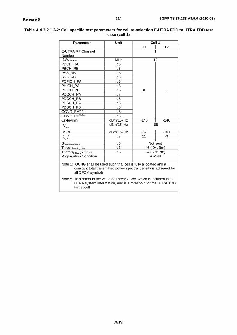
3GPP
114Release 8 3GPP TS 36.133 V8.9.0 (2010-03)
Table A.4.3.2.1.2-2: Cell specific test parameters for cell re-selection E-UTRA FDD to UTRA TDD test case (cell 1)
Parameter Unit Cell 1 T1 T2
E-UTRA RF Channel Number
1
BWchannel MHz 10 PBCH_RA dB
0 0
PBCH_RB dB PSS_RB dB SSS_RB dB PCFICH_PA dB PHICH_PA dB PHICH_PB dB PDCCH_PA dB PDCCH_PB dB PDSCH_PA dB PDSCH_PB dB OCNG_RANote1 dB OCNG_RBNote1 dB Qrxlevmin dBm/15kHz -140 -140
ocN dBm/15kHz -98
RSRP dBm/15kHz -87 -101
ots IÊ dB 11 -3
Snonintrasearch dB Not sent Threshserving, low dB 46 (-94dBm) Threshx, low (Note2) dB 24 (-79dBm) Propagation Condition AWGN
Note 1: OCNG shall be used such that cell is fully allocated and a constant total transmitted power spectral density is achieved for all OFDM symbols.
Note2: This refers to the value of Threshx, low which is included in E-UTRA system information, and is a threshold for the UTRA TDD target cell
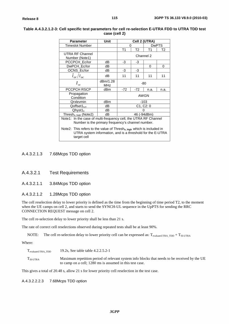
3GPP
115Release 8 3GPP TS 36.133 V8.9.0 (2010-03)
Table A.4.3.2.1.2-3: Cell specific test parameters for cell re-selection E-UTRA FDD to UTRA TDD test case (cell 2)
Parameter Unit Cell 2 (UTRA) Timeslot Number 0 DwPTS
T1 T2 T1 T2 UTRA RF Channel
Number (Note1) Channel 2
PCCPCH_Ec/Ior dB -3 -3 DwPCH_Ec/Ior dB 0 0 OCNS_Ec/Ior dB -3 -3
ocor II dB 11 11 11 11
ocI dBm/1.28 MHz -80
PCCPCH RSCP dBm -72 -72 n.a. n.a. Propagation
Condition AWGN
Qrxlevmin dBm -103 Qoffset1s,n dB C1, C2: 0
Qhyst1s dB 0 Threshx, high (Note2) dB 46 (-94dBm)
Note1: In the case of multi-frequency cell, the UTRA RF Channel Number is the primary frequency’s channel number.
Note2: This refers to the value of Threshx, high which is included in UTRA system information, and is a threshold for the E-UTRA target cell
A.4.3.2.1.3 7.68Mcps TDD option
A.4.3.2.1 Test Requirements
A.4.3.2.1.1 3.84Mcps TDD option
A.4.3.2.1.2 1.28Mcps TDD option
The cell reselection delay to lower priority is defined as the time from the beginning of time period T2, to the moment when the UE camps on cell 2, and starts to send the SYNCH-UL sequence in the UpPTS for sending the RRC CONNECTION REQUEST message on cell 2.
The cell re-selection delay to lower priority shall be less than 21 s.
The rate of correct cell reselections observed during repeated tests shall be at least 90%.
NOTE: The cell re-selection delay to lower priority cell can be expressed as: TevaluateUTRA_TDD + TSI-UTRA
Where:
TevaluateUTRA_TDD 19.2s, See table table 4.2.2.5.2-1
TSI-UTRA Maximum repetition period of relevant system info blocks that needs to be received by the UE to camp on a cell; 1280 ms is assumed in this test case.
This gives a total of 20.48 s, allow 21 s for lower priority cell reselection in the test case.
A.4.3.2.2.2.3 7.68Mcps TDD option
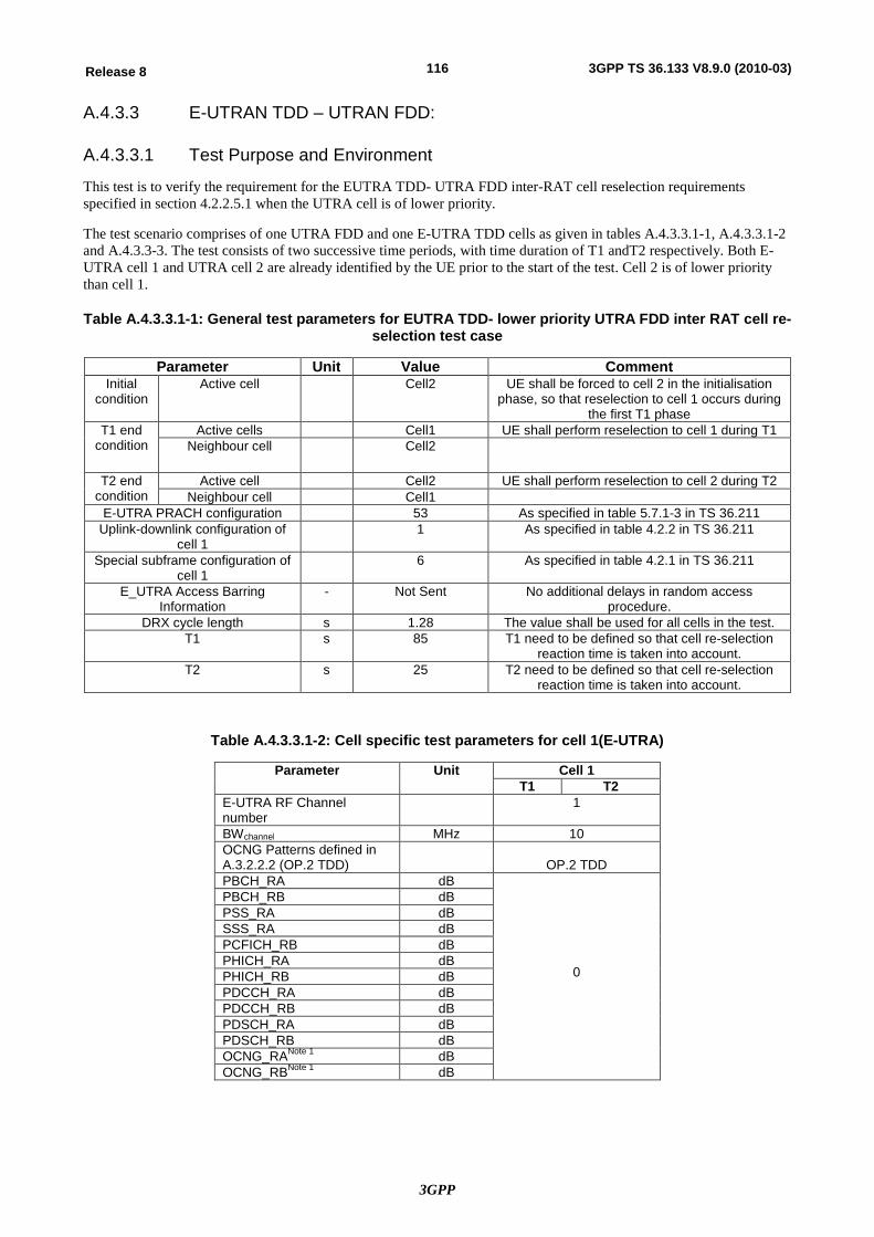
3GPP
116Release 8 3GPP TS 36.133 V8.9.0 (2010-03)
A.4.3.3 E-UTRAN TDD – UTRAN FDD:
A.4.3.3.1 Test Purpose and Environment
This test is to verify the requirement for the EUTRA TDD- UTRA FDD inter-RAT cell reselection requirements specified in section 4.2.2.5.1 when the UTRA cell is of lower priority.
The test scenario comprises of one UTRA FDD and one E-UTRA TDD cells as given in tables A.4.3.3.1-1, A.4.3.3.1-2 and A.4.3.3-3. The test consists of two successive time periods, with time duration of T1 andT2 respectively. Both E-UTRA cell 1 and UTRA cell 2 are already identified by the UE prior to the start of the test. Cell 2 is of lower priority than cell 1.
Table A.4.3.3.1-1: General test parameters for EUTRA TDD- lower priority UTRA FDD inter RAT cell re-selection test case
Parameter Unit Value Comment Initial
condition Active cell Cell2 UE shall be forced to cell 2 in the initialisation
phase, so that reselection to cell 1 occurs during the first T1 phase
T1 end condition
Active cells Cell1 UE shall perform reselection to cell 1 during T1 Neighbour cell Cell2
T2 end condition
Active cell Cell2 UE shall perform reselection to cell 2 during T2 Neighbour cell Cell1
E-UTRA PRACH configuration 53 As specified in table 5.7.1-3 in TS 36.211 Uplink-downlink configuration of
cell 1 1 As specified in table 4.2.2 in TS 36.211
Special subframe configuration of cell 1
6 As specified in table 4.2.1 in TS 36.211
E_UTRA Access Barring Information
- Not Sent No additional delays in random access procedure.
DRX cycle length s 1.28 The value shall be used for all cells in the test. T1 s 85 T1 need to be defined so that cell re-selection
reaction time is taken into account. T2 s 25 T2 need to be defined so that cell re-selection
reaction time is taken into account.
Table A.4.3.3.1-2: Cell specific test parameters for cell 1(E-UTRA)
Parameter Unit Cell 1 T1 T2
E-UTRA RF Channel number
1
BWchannel MHz 10 OCNG Patterns defined in A.3.2.2.2 (OP.2 TDD)
OP.2 TDD
PBCH_RA dB
0
PBCH_RB dB PSS_RA dB SSS_RA dB PCFICH_RB dB PHICH_RA dB PHICH_RB dB PDCCH_RA dB PDCCH_RB dB PDSCH_RA dB PDSCH_RB dB OCNG_RANote 1 dB OCNG_RBNote 1 dB
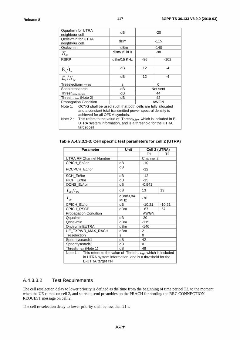
3GPP
117Release 8 3GPP TS 36.133 V8.9.0 (2010-03)
Qqualmin for UTRA neighbour cell dB -20
Qrxlevmin for UTRA neighbour cell dBm -115
Qrxlevmin dBm -140
ocN dBm/15 kHz -98
RSRP dBm/15 KHz -86 -102
ots IÊ dB 12 -4
ocs NÊ dB 12 -4
TreselectionEUTRAN s 0 Snonintrasearch dB Not sent Threshserving, low dB 44 Threshx, low (Note 2) dB 42 Propagation Condition AWGN Note 1: OCNG shall be used such that both cells are fully allocated
and a constant total transmitted power spectral density is achieved for all OFDM symbols.
Note 2 : This refers to the value of Threshx, low which is included in E-UTRA system information, and is a threshold for the UTRA target cell
Table A.4.3.3.1-3: Cell specific test parameters for cell 2 (UTRA)
Parameter Unit Cell 2 (UTRA) T1 T2
UTRA RF Channel Number Channel 2 CPICH_Ec/Ior dB -10
PCCPCH_Ec/Ior dB -12
SCH_Ec/Ior dB -12 PICH_Ec/Ior dB -15 OCNS_Ec/Ior dB -0.941
ocor II dB 13 13
ocI dBm/3,84 MHz -70
CPICH_Ec/Io dB -10.21 -10.21 CPICH_RSCP dBm -67 -67 Propagation Condition AWGN Qqualmin dB -20 Qrxlevmin dBm -115 QrxlevminEUTRA dBm -140 UE_TXPWR_MAX_RACH dBm 21 Treselection s 0 Sprioritysearch1 dB 42 Sprioritysearch2 dB 0 Threshx, high (Note 1) dB 48 Note 1 : This refers to the value of Threshx, high which is included
in UTRA system information, and is a threshold for the E-UTRA target cell
A.4.3.3.2 Test Requirements
The cell reselection delay to lower priority is defined as the time from the beginning of time period T2, to the moment when the UE camps on cell 2, and starts to send preambles on the PRACH for sending the RRC CONNECTION REQUEST message on cell 2.
The cell re-selection delay to lower priority shall be less than 21 s.
3GPP
118Release 8 3GPP TS 36.133 V8.9.0 (2010-03)
The rate of correct cell reselections observed during repeated tests shall be at least 90%.
NOTE: The cell re-selection delay to lower priority cell can be expressed as: TevaluateUTRA_FDD + TSI-UTRA
Where:
TevaluateUTRA-FDD See Table 4.2.2.5.1-1
TSI-UTRA Maximum repetition period of relevant system info blocks that needs to be received by the UE to camp on a cell; 1280 ms is assumed in this test case.
This gives a total of 20.48 s for lower priority cell reselection, allow 21 s.
A.4.3.4 E-UTRAN TDD – UTRAN TDD:
A.4.3.4.1 E-UTRA to UTRA TDD cell re-selection: UTRA is of higher priority
A.4.3.4.1.1 Test Purpose and Environment
A.4.3.4.1.1.1 3.84 Mcps TDD option
A.4.3.4.1.1.2 1.28 Mcps TDD option
This test is to verify the requirement for the E-UTRA TDD to UTRA TDD inter-RAT cell re-selection requirements specified in section 4.2.2.5 when the UTRA cell is of higher priority.
This test scenario comprised of 1 E-UTRA TDD serving cell, and 1 UTRA TDD cell to be re-selected. Test parameters are given in table A.4.3.4.1.1.2-1, A.4.3.4.1.1.2-2, and A.4.3.4.1.1.2-3. The test consists of three successive time periods, with time duration of T1, T2 and T3 respectively. Both UTRA cell 1 and E-UTRA cell 2 are already identified by the UE prior to the start of the test. Cell 2 is of higher priority than cell 1.
The ranking of the cells shall be made according to the cell reselection criteria specified in TS36.304.
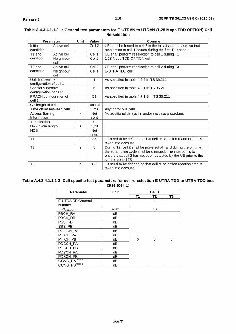
3GPP
119Release 8 3GPP TS 36.133 V8.9.0 (2010-03)
Table A.4.3.4.1.1.2-1: General test parameters for E-UTRAN to UTRAN (1.28 Mcps TDD OPTION) Cell Re-selection
Parameter Unit Value Comment Initial condition
Active cell Cell 2 UE shall be forced to cell 2 in the initialisation phase, so that reselection to cell 1 occurs during the first T1 phase
T1 end condition
Active cell Cell1 UE shall perform reselection to cell 1 during T1 Neighbour cell
Cell2 1.28 Mcps TDD OPTION cell
T3 end condition
Active cell Cell2 UE shall perform reselection to cell 2 during T3 Neighbour cell
Cell1 E-UTRA TDD cell
Uplink-downlink configuration of cell 1
1 As specified in table 4.2.2 in TS 36.211
Special subframe configuration of cell 1
6 As specified in table 4.2.1 in TS 36.211
PRACH configuration of cell 1
53 As specified in table 4.7.1-3 in TS 36.211
CP length of cell 1 Normal Time offset between cells 3 ms Asynchronous cells Access Barring Information
- Not sent
No additional delays in random access procedure.
Treselection s 0 DRX cycle length s 1,28 HCS Not
used
T1 s 25 T1 need to be defined so that cell re-selection reaction time is taken into account.
T2 s 5 During T2, cell 2 shall be powered off, and during the off time the scrambling code shall be changed, The intention is to ensure that cell 2 has not been detected by the UE prior to the start of period T3
T3 s 85 T3 need to be defined so that cell re-selection reaction time is taken into account.
Table A.4.3.4.1.1.2-2: Cell specific test parameters for cell re-selection E-UTRA TDD to UTRA TDD test case (cell 1)
Parameter Unit Cell 1 T1 T2 T3
E-UTRA RF Channel Number
1
BWchannel MHz 10 PBCH_RA dB
0 0 0
PBCH_RB dB PSS_RB dB SSS_RB dB PCFICH_PA dB PHICH_PA dB PHICH_PB dB PDCCH_PA dB PDCCH_PB dB PDSCH_PA dB PDSCH_PB dB OCNG_RANote 1 dB OCNG_RBNote 1 dB
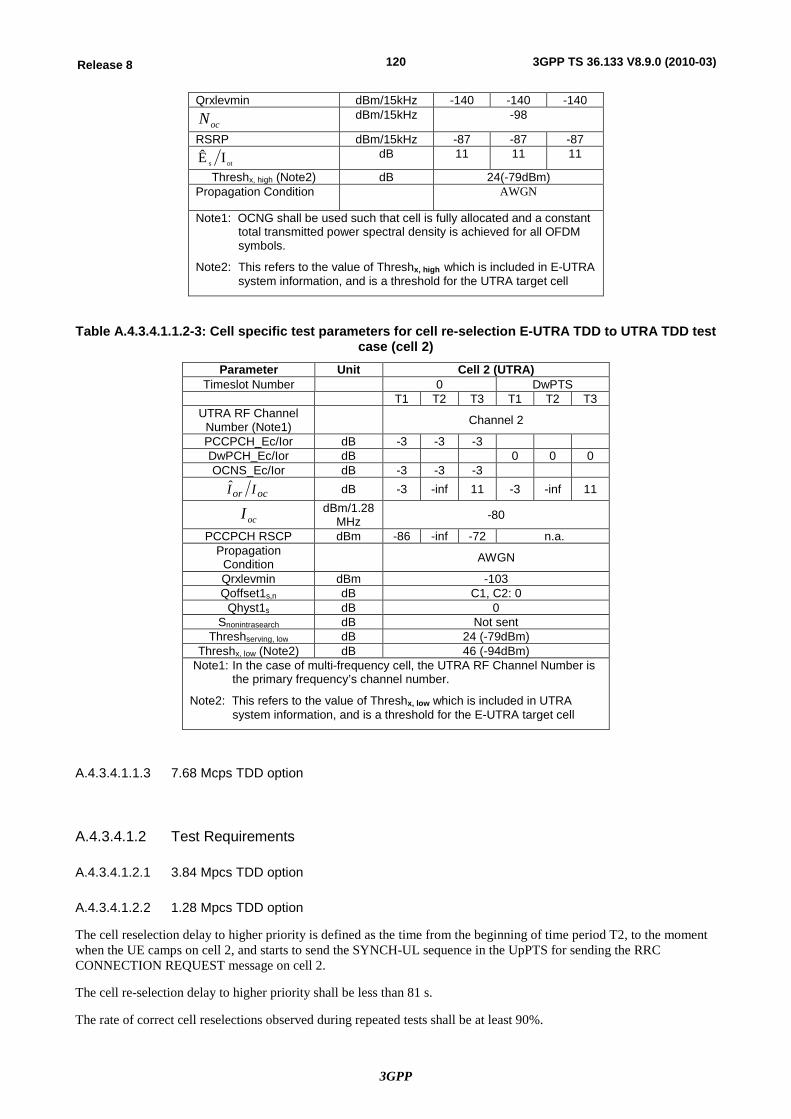
3GPP
120Release 8 3GPP TS 36.133 V8.9.0 (2010-03)
Qrxlevmin dBm/15kHz -140 -140 -140
ocN dBm/15kHz -98
RSRP dBm/15kHz -87 -87 -87
ots IÊ dB 11 11 11
Threshx, high (Note2) dB 24(-79dBm) Propagation Condition AWGN
Note1: OCNG shall be used such that cell is fully allocated and a constant total transmitted power spectral density is achieved for all OFDM symbols.
Note2: This refers to the value of Threshx, high which is included in E-UTRA system information, and is a threshold for the UTRA target cell
Table A.4.3.4.1.1.2-3: Cell specific test parameters for cell re-selection E-UTRA TDD to UTRA TDD test case (cell 2)
Parameter Unit Cell 2 (UTRA) Timeslot Number 0 DwPTS
T1 T2 T3 T1 T2 T3 UTRA RF Channel
Number (Note1) Channel 2
PCCPCH_Ec/Ior dB -3 -3 -3 DwPCH_Ec/Ior dB 0 0 0 OCNS_Ec/Ior dB -3 -3 -3
ocor II dB -3 -inf 11 -3 -inf 11
ocI dBm/1.28 MHz -80
PCCPCH RSCP dBm -86 -inf -72 n.a. Propagation
Condition AWGN
Qrxlevmin dBm -103 Qoffset1s,n dB C1, C2: 0
Qhyst1s dB 0 Snonintrasearch dB Not sent
Threshserving, low dB 24 (-79dBm) Threshx, low (Note2) dB 46 (-94dBm)
Note1: In the case of multi-frequency cell, the UTRA RF Channel Number is the primary frequency’s channel number.
Note2: This refers to the value of Threshx, low which is included in UTRA system information, and is a threshold for the E-UTRA target cell
A.4.3.4.1.1.3 7.68 Mcps TDD option
A.4.3.4.1.2 Test Requirements
A.4.3.4.1.2.1 3.84 Mpcs TDD option
A.4.3.4.1.2.2 1.28 Mpcs TDD option
The cell reselection delay to higher priority is defined as the time from the beginning of time period T2, to the moment when the UE camps on cell 2, and starts to send the SYNCH-UL sequence in the UpPTS for sending the RRC CONNECTION REQUEST message on cell 2.
The cell re-selection delay to higher priority shall be less than 81 s.
The rate of correct cell reselections observed during repeated tests shall be at least 90%.
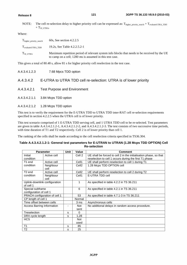
3GPP
121Release 8 3GPP TS 36.133 V8.9.0 (2010-03)
NOTE: The cell re-selection delay to higher priority cell can be expressed as: Thigher_priority_search + TevaluateUTRA_TDD + TSI_UTRA,
Where:
Thigher_priority_search 60s, See section 4.2.2.5
TevaluateUTRA_TDD 19.2s, See Table 4.2.2.5.2-1
TSI_UTRA Maximum repetition period of relevant system info blocks that needs to be received by the UE to camp on a cell; 1280 ms is assumed in this test case.
This gives a total of 80.48 s, allow 81 s for higher priority cell reselection in the test case.
A.4.3.4.1.2.3 7.68 Mpcs TDD option
A.4.3.4.2 E-UTRA to UTRA TDD cell re-selection: UTRA is of lower priority
A.4.3.4.2.1 Test Purpose and Environment
A.4.3.4.2.1.1 3.84 Mcps TDD option
A.4.3.4.2.1.2 1.28 Mcps TDD option
This test is to verify the requirement for the E-UTRA TDD to UTRA TDD inter-RAT cell re-selection requirements specified in section 4.2.2.5 when the UTRA cell is of lower priority.
This test scenario comprised of 1 E-UTRA TDD serving cell, and 1 UTRA TDD cell to be re-selected. Test parameters are given in table A.4.3.4.2.1.2-1, A.4.3.4.2.1.2-2, and A.4.3.4.2.1.2-3. The test consists of two successive time periods, with time duration of T1 and T2 respectively. Cell 2 is of lower priority than cell 1.
The ranking of the cells shall be made according to the cell reselection criteria specified in TS36.304.
Table A.4.3.4.2.1.2-1: General test parameters for E-UTRAN to UTRAN (1.28 Mcps TDD OPTION) Cell Re-selection
Parameter Unit Value Comment Initial condition
Active cell Cell 2 UE shall be forced to cell 2 in the initialisation phase, so that reselection to cell 1 occurs during the first T1 phase
T1 end condition
Active cell Cell1 UE shall perform reselection to cell 1 during T1 Neighbour cell
Cell2 1.28 Mcps TDD OPTION cell
T2 end condition
Active cell Cell2 UE shall perform reselection to cell 2 during T2 Neighbour cell
Cell1 E-UTRA TDD cell
Uplink-downlink configuration of cell 1
1 As specified in table 4.2.2 in TS 36.211
Special subframe configuration of cell 1
6 As specified in table 4.2.1 in TS 36.211
PRACH configuration of cell 1 53 As specified in table 4.7.1-3 in TS 36.211 CP length of cell 1 Normal Time offset between cells 3 ms Asynchronous cells Access Barring Information - Not
sent No additional delays in random access procedure.
Treselection s 0 DRX cycle length s 1,28 HCS Not
used
T1 s 85 T2 s 25
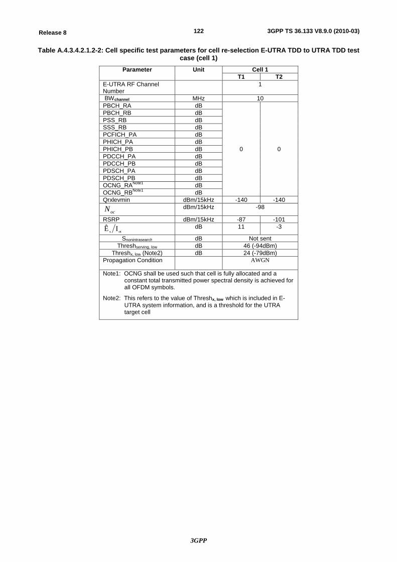
3GPP
122Release 8 3GPP TS 36.133 V8.9.0 (2010-03)
Table A.4.3.4.2.1.2-2: Cell specific test parameters for cell re-selection E-UTRA TDD to UTRA TDD test case (cell 1)
Parameter Unit Cell 1 T1 T2
E-UTRA RF Channel Number
1
BWchannel MHz 10 PBCH_RA dB
0 0
PBCH_RB dB PSS_RB dB SSS_RB dB PCFICH_PA dB PHICH_PA dB PHICH_PB dB PDCCH_PA dB PDCCH_PB dB PDSCH_PA dB PDSCH_PB dB OCNG_RANote1 dB OCNG_RBNote1 dB Qrxlevmin dBm/15kHz -140 -140
ocN dBm/15kHz -98
RSRP dBm/15kHz -87 -101
ots IÊ dB 11 -3
Snonintrasearch dB Not sent Threshserving, low dB 46 (-94dBm)
Threshx, low (Note2) dB 24 (-79dBm) Propagation Condition AWGN
Note1: OCNG shall be used such that cell is fully allocated and a constant total transmitted power spectral density is achieved for all OFDM symbols.
Note2: This refers to the value of Threshx, low which is included in E-UTRA system information, and is a threshold for the UTRA target cell
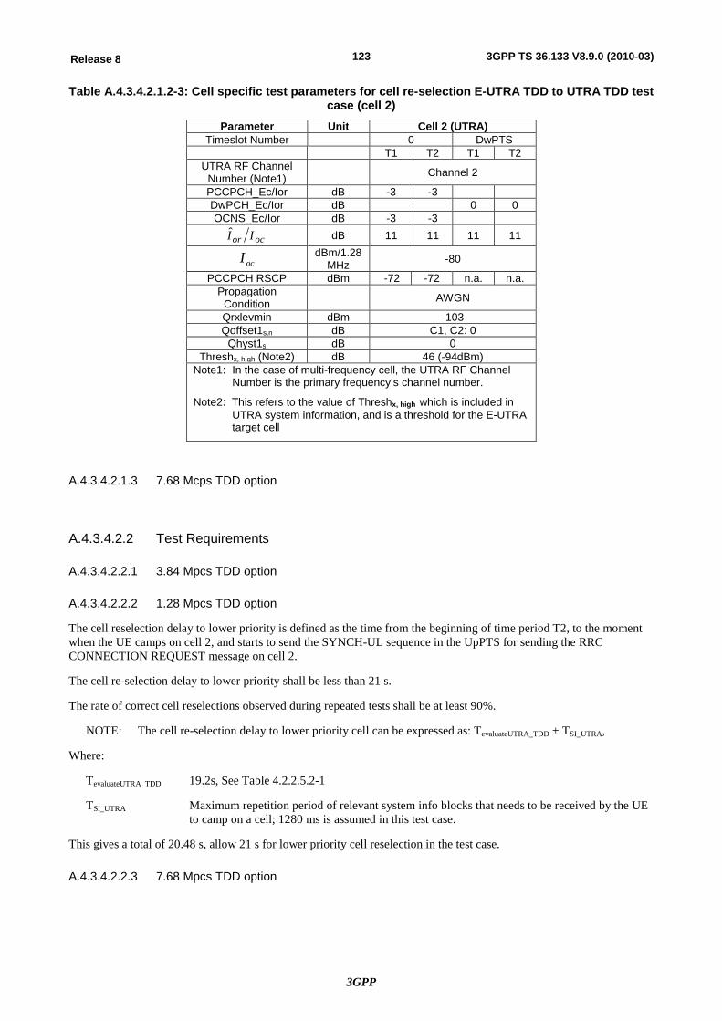
3GPP
123Release 8 3GPP TS 36.133 V8.9.0 (2010-03)
Table A.4.3.4.2.1.2-3: Cell specific test parameters for cell re-selection E-UTRA TDD to UTRA TDD test case (cell 2)
Parameter Unit Cell 2 (UTRA) Timeslot Number 0 DwPTS
T1 T2 T1 T2 UTRA RF Channel
Number (Note1) Channel 2
PCCPCH_Ec/Ior dB -3 -3 DwPCH_Ec/Ior dB 0 0 OCNS_Ec/Ior dB -3 -3
ocor II dB 11 11 11 11
ocI dBm/1.28 MHz -80
PCCPCH RSCP dBm -72 -72 n.a. n.a. Propagation
Condition AWGN
Qrxlevmin dBm -103 Qoffset1s,n dB C1, C2: 0
Qhyst1s dB 0 Threshx, high (Note2) dB 46 (-94dBm)
Note1: In the case of multi-frequency cell, the UTRA RF Channel Number is the primary frequency’s channel number.
Note2: This refers to the value of Threshx, high which is included in UTRA system information, and is a threshold for the E-UTRA target cell
A.4.3.4.2.1.3 7.68 Mcps TDD option
A.4.3.4.2.2 Test Requirements
A.4.3.4.2.2.1 3.84 Mpcs TDD option
A.4.3.4.2.2.2 1.28 Mpcs TDD option
The cell reselection delay to lower priority is defined as the time from the beginning of time period T2, to the moment when the UE camps on cell 2, and starts to send the SYNCH-UL sequence in the UpPTS for sending the RRC CONNECTION REQUEST message on cell 2.
The cell re-selection delay to lower priority shall be less than 21 s.
The rate of correct cell reselections observed during repeated tests shall be at least 90%.
NOTE: The cell re-selection delay to lower priority cell can be expressed as: TevaluateUTRA_TDD + TSI_UTRA,
Where:
TevaluateUTRA_TDD 19.2s, See Table 4.2.2.5.2-1
TSI_UTRA Maximum repetition period of relevant system info blocks that needs to be received by the UE to camp on a cell; 1280 ms is assumed in this test case.
This gives a total of 20.48 s, allow 21 s for lower priority cell reselection in the test case.
A.4.3.4.2.2.3 7.68 Mpcs TDD option
3GPP
124Release 8 3GPP TS 36.133 V8.9.0 (2010-03)
A.4.4 E-UTRAN to GSM Cell Re-Selection
A.4.4.1 E-UTRAN FDD – GSM:
A.4.4.1.1 Test Purpose and Environment
This test is to verify the requirement for the E-UTRAN FDD to GSM cell re-selection delay reported in section 4.2.2.5.
This scenario implies the presence of 1 E-UTRAN serving cell, and 1 GSM cell to be re-selected. The UE is requested to monitor neighbouring cells on 1 E-UTRA carrier and 12 GSM cells. Test parameters are given in Table, A.4.4.1-1, A.4.4.1-2, A.4.4.1-3. E-UTRA FDD cell (Cell 1) and GSM cell (cell 2) shall belong to different Location Areas. The test comprises two successive time periods, T1 and T2. During initialization before the start of the test, the UE is camped on cell 1. By the end of T1, the UE has identified BSIC on the GSM BCCH carrier of cell 2 but the signal levels do not meet the reselection criterion during T1. At the start of T2, the signal levels change such that cell 2 satisfies reselection criterion. The GSM layer is configured at a lower priority than the serving E-UTRA FDD layer.
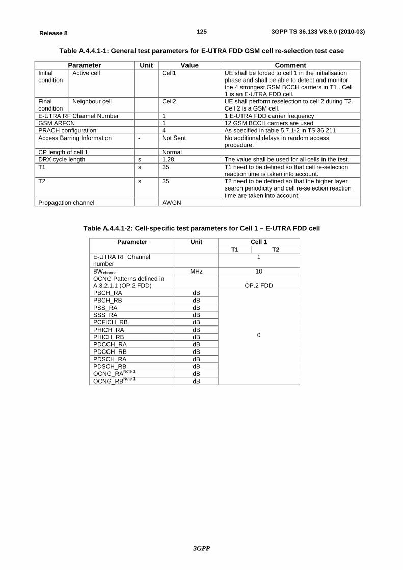
3GPP
125Release 8 3GPP TS 36.133 V8.9.0 (2010-03)
Table A.4.4.1-1: General test parameters for E-UTRA FDD GSM cell re-selection test case
Parameter Unit Value Comment Initial condition
Active cell Cell1 UE shall be forced to cell 1 in the initialisation phase and shall be able to detect and monitor the 4 strongest GSM BCCH carriers in T1 . Cell 1 is an E-UTRA FDD cell.
Final condition
Neighbour cell Cell2 UE shall perform reselection to cell 2 during T2. Cell 2 is a GSM cell.
E-UTRA RF Channel Number 1 1 E-UTRA FDD carrier frequency GSM ARFCN 1 12 GSM BCCH carriers are used PRACH configuration 4 As specified in table 5.7.1-2 in TS 36.211 Access Barring Information - Not Sent No additional delays in random access
procedure. CP length of cell 1 Normal DRX cycle length s 1.28 The value shall be used for all cells in the test. T1 s 35 T1 need to be defined so that cell re-selection
reaction time is taken into account. T2 s 35 T2 need to be defined so that the higher layer
search periodicity and cell re-selection reaction time are taken into account.
Propagation channel AWGN
Table A.4.4.1-2: Cell-specific test parameters for Cell 1 – E-UTRA FDD cell
Parameter Unit Cell 1 T1 T2
E-UTRA RF Channel number
1
BWchannel MHz 10 OCNG Patterns defined in A.3.2.1.1 (OP.2 FDD)
OP.2 FDD
PBCH_RA dB
0
PBCH_RB dB PSS_RA dB SSS_RA dB PCFICH_RB dB PHICH_RA dB PHICH_RB dB PDCCH_RA dB PDCCH_RB dB PDSCH_RA dB PDSCH_RB dB OCNG_RANote 1 dB OCNG_RBNote 1 dB
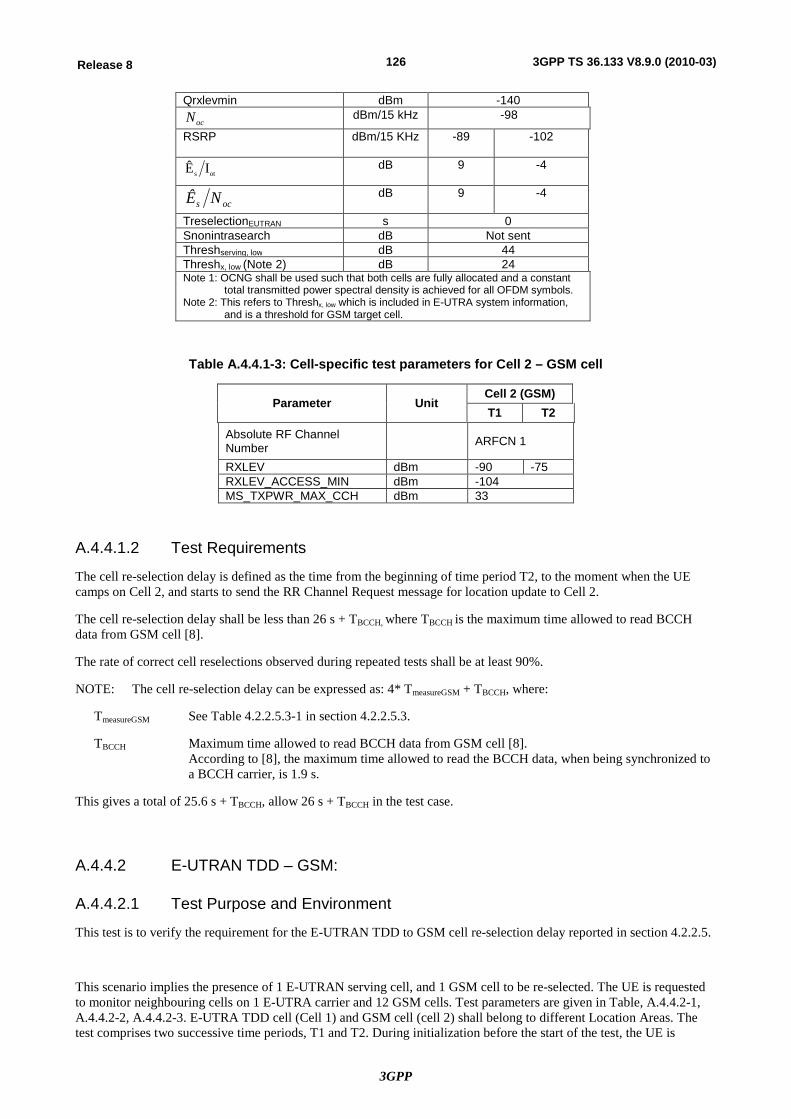
3GPP
126Release 8 3GPP TS 36.133 V8.9.0 (2010-03)
Qrxlevmin dBm -140
ocN dBm/15 kHz -98
RSRP dBm/15 KHz -89 -102
ots IÊ dB 9 -4
ocs NÊ dB 9 -4
TreselectionEUTRAN s 0 Snonintrasearch dB Not sent Threshserving, low dB 44 Threshx, low (Note 2) dB 24 Note 1: OCNG shall be used such that both cells are fully allocated and a constant
total transmitted power spectral density is achieved for all OFDM symbols. Note 2: This refers to Threshx, low which is included in E-UTRA system information,
and is a threshold for GSM target cell.
Table A.4.4.1-3: Cell-specific test parameters for Cell 2 – GSM cell
Parameter Unit Cell 2 (GSM) T1 T2
Absolute RF Channel Number ARFCN 1
RXLEV dBm -90 -75 RXLEV_ACCESS_MIN dBm -104 MS_TXPWR_MAX_CCH dBm 33
A.4.4.1.2 Test Requirements
The cell re-selection delay is defined as the time from the beginning of time period T2, to the moment when the UE camps on Cell 2, and starts to send the RR Channel Request message for location update to Cell 2.
The cell re-selection delay shall be less than 26 s + TBCCH, where TBCCH is the maximum time allowed to read BCCH data from GSM cell [8].
The rate of correct cell reselections observed during repeated tests shall be at least 90%.
NOTE: The cell re-selection delay can be expressed as: 4* TmeasureGSM + TBCCH, where:
TmeasureGSM See Table 4.2.2.5.3-1 in section 4.2.2.5.3.
TBCCH Maximum time allowed to read BCCH data from GSM cell [8]. According to [8], the maximum time allowed to read the BCCH data, when being synchronized to a BCCH carrier, is 1.9 s.
This gives a total of 25.6 s + TBCCH, allow 26 s + TBCCH in the test case.
A.4.4.2 E-UTRAN TDD – GSM:
A.4.4.2.1 Test Purpose and Environment
This test is to verify the requirement for the E-UTRAN TDD to GSM cell re-selection delay reported in section 4.2.2.5.
This scenario implies the presence of 1 E-UTRAN serving cell, and 1 GSM cell to be re-selected. The UE is requested to monitor neighbouring cells on 1 E-UTRA carrier and 12 GSM cells. Test parameters are given in Table, A.4.4.2-1, A.4.4.2-2, A.4.4.2-3. E-UTRA TDD cell (Cell 1) and GSM cell (cell 2) shall belong to different Location Areas. The test comprises two successive time periods, T1 and T2. During initialization before the start of the test, the UE is
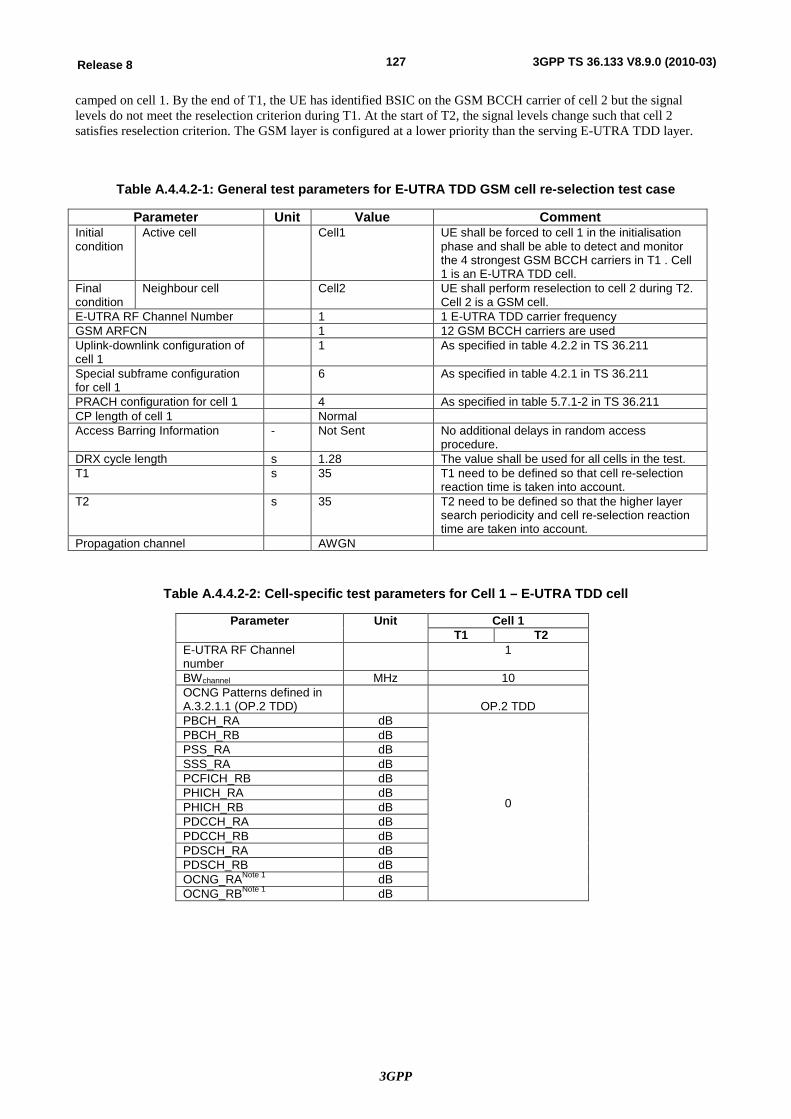
3GPP
127Release 8 3GPP TS 36.133 V8.9.0 (2010-03)
camped on cell 1. By the end of T1, the UE has identified BSIC on the GSM BCCH carrier of cell 2 but the signal levels do not meet the reselection criterion during T1. At the start of T2, the signal levels change such that cell 2 satisfies reselection criterion. The GSM layer is configured at a lower priority than the serving E-UTRA TDD layer.
Table A.4.4.2-1: General test parameters for E-UTRA TDD GSM cell re-selection test case
Parameter Unit Value Comment Initial condition
Active cell Cell1 UE shall be forced to cell 1 in the initialisation phase and shall be able to detect and monitor the 4 strongest GSM BCCH carriers in T1 . Cell 1 is an E-UTRA TDD cell.
Final condition
Neighbour cell Cell2 UE shall perform reselection to cell 2 during T2. Cell 2 is a GSM cell.
E-UTRA RF Channel Number 1 1 E-UTRA TDD carrier frequency GSM ARFCN 1 12 GSM BCCH carriers are used Uplink-downlink configuration of cell 1
1 As specified in table 4.2.2 in TS 36.211
Special subframe configuration for cell 1
6 As specified in table 4.2.1 in TS 36.211
PRACH configuration for cell 1 4 As specified in table 5.7.1-2 in TS 36.211 CP length of cell 1 Normal Access Barring Information - Not Sent No additional delays in random access
procedure. DRX cycle length s 1.28 The value shall be used for all cells in the test. T1 s 35 T1 need to be defined so that cell re-selection
reaction time is taken into account. T2 s 35 T2 need to be defined so that the higher layer
search periodicity and cell re-selection reaction time are taken into account.
Propagation channel AWGN
Table A.4.4.2-2: Cell-specific test parameters for Cell 1 – E-UTRA TDD cell
Parameter Unit Cell 1 T1 T2
E-UTRA RF Channel number
1
BWchannel MHz 10 OCNG Patterns defined in A.3.2.1.1 (OP.2 TDD)
OP.2 TDD
PBCH_RA dB
0
PBCH_RB dB PSS_RA dB SSS_RA dB PCFICH_RB dB PHICH_RA dB PHICH_RB dB PDCCH_RA dB PDCCH_RB dB PDSCH_RA dB PDSCH_RB dB OCNG_RANote 1 dB OCNG_RBNote 1 dB
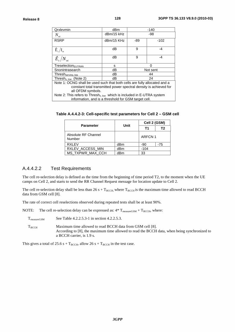
3GPP
128Release 8 3GPP TS 36.133 V8.9.0 (2010-03)
Qrxlevmin dBm -140
ocN dBm/15 kHz -98
RSRP dBm/15 KHz -89 -102
ots IÊ dB 9 -4
ocs NÊ dB 9 -4
TreselectionEUTRAN s 0 Snonintrasearch dB Not sent Threshserving, low dB 44 Threshx, low (Note 2) dB 24 Note 1: OCNG shall be used such that both cells are fully allocated and a
constant total transmitted power spectral density is achieved for all OFDM symbols.
Note 2: This refers to Threshx, low which is included in E-UTRA system information, and is a threshold for GSM target cell.
Table A.4.4.2-3: Cell-specific test parameters for Cell 2 – GSM cell
Parameter Unit Cell 2 (GSM) T1 T2
Absolute RF Channel Number ARFCN 1
RXLEV dBm -90 -75 RXLEV_ACCESS_MIN dBm -104 MS_TXPWR_MAX_CCH dBm 33
A.4.4.2.2 Test Requirements
The cell re-selection delay is defined as the time from the beginning of time period T2, to the moment when the UE camps on Cell 2, and starts to send the RR Channel Request message for location update to Cell 2.
The cell re-selection delay shall be less than 26 s + TBCCH, where TBCCH is the maximum time allowed to read BCCH data from GSM cell [8].
The rate of correct cell reselections observed during repeated tests shall be at least 90%.
NOTE: The cell re-selection delay can be expressed as: 4* TmeasureGSM + TBCCH, where:
TmeasureGSM See Table 4.2.2.5.3-1 in section 4.2.2.5.3.
TBCCH Maximum time allowed to read BCCH data from GSM cell [8]. According to [8], the maximum time allowed to read the BCCH data, when being synchronized to a BCCH carrier, is 1.9 s.
This gives a total of 25.6 s + TBCCH, allow 26 s + TBCCH in the test case.
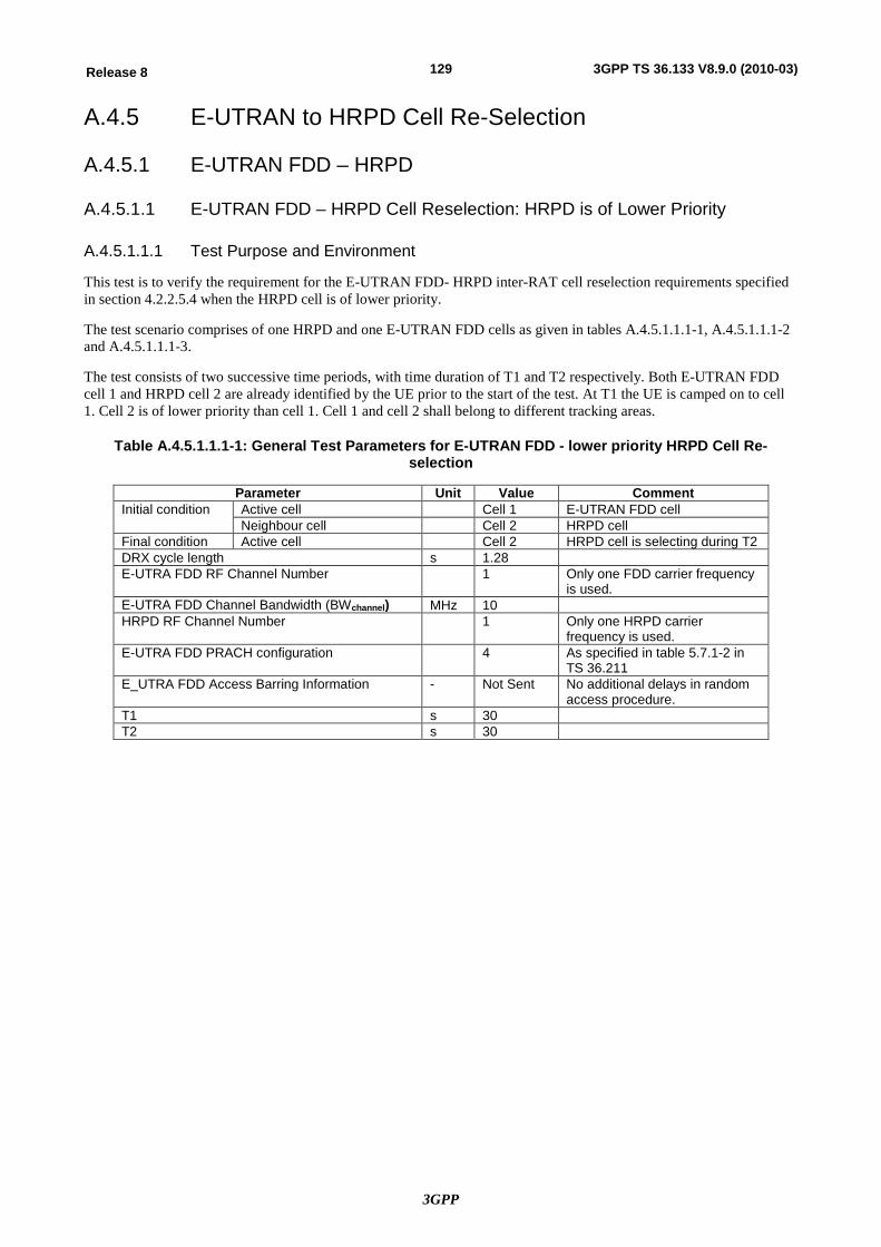
3GPP
129Release 8 3GPP TS 36.133 V8.9.0 (2010-03)
A.4.5 E-UTRAN to HRPD Cell Re-Selection
A.4.5.1 E-UTRAN FDD – HRPD
A.4.5.1.1 E-UTRAN FDD – HRPD Cell Reselection: HRPD is of Lower Priority
A.4.5.1.1.1 Test Purpose and Environment
This test is to verify the requirement for the E-UTRAN FDD- HRPD inter-RAT cell reselection requirements specified in section 4.2.2.5.4 when the HRPD cell is of lower priority.
The test scenario comprises of one HRPD and one E-UTRAN FDD cells as given in tables A.4.5.1.1.1-1, A.4.5.1.1.1-2 and A.4.5.1.1.1-3.
The test consists of two successive time periods, with time duration of T1 and T2 respectively. Both E-UTRAN FDD cell 1 and HRPD cell 2 are already identified by the UE prior to the start of the test. At T1 the UE is camped on to cell 1. Cell 2 is of lower priority than cell 1. Cell 1 and cell 2 shall belong to different tracking areas.
Table A.4.5.1.1.1-1: General Test Parameters for E-UTRAN FDD - lower priority HRPD Cell Re-selection
Parameter Unit Value Comment Initial condition Active cell Cell 1 E-UTRAN FDD cell
Neighbour cell Cell 2 HRPD cell Final condition Active cell Cell 2 HRPD cell is selecting during T2 DRX cycle length s 1.28 E-UTRA FDD RF Channel Number 1 Only one FDD carrier frequency
is used. E-UTRA FDD Channel Bandwidth (BWchannel) MHz 10 HRPD RF Channel Number 1 Only one HRPD carrier
frequency is used. E-UTRA FDD PRACH configuration 4 As specified in table 5.7.1-2 in
TS 36.211 E_UTRA FDD Access Barring Information - Not Sent No additional delays in random
access procedure. T1 s 30 T2 s 30
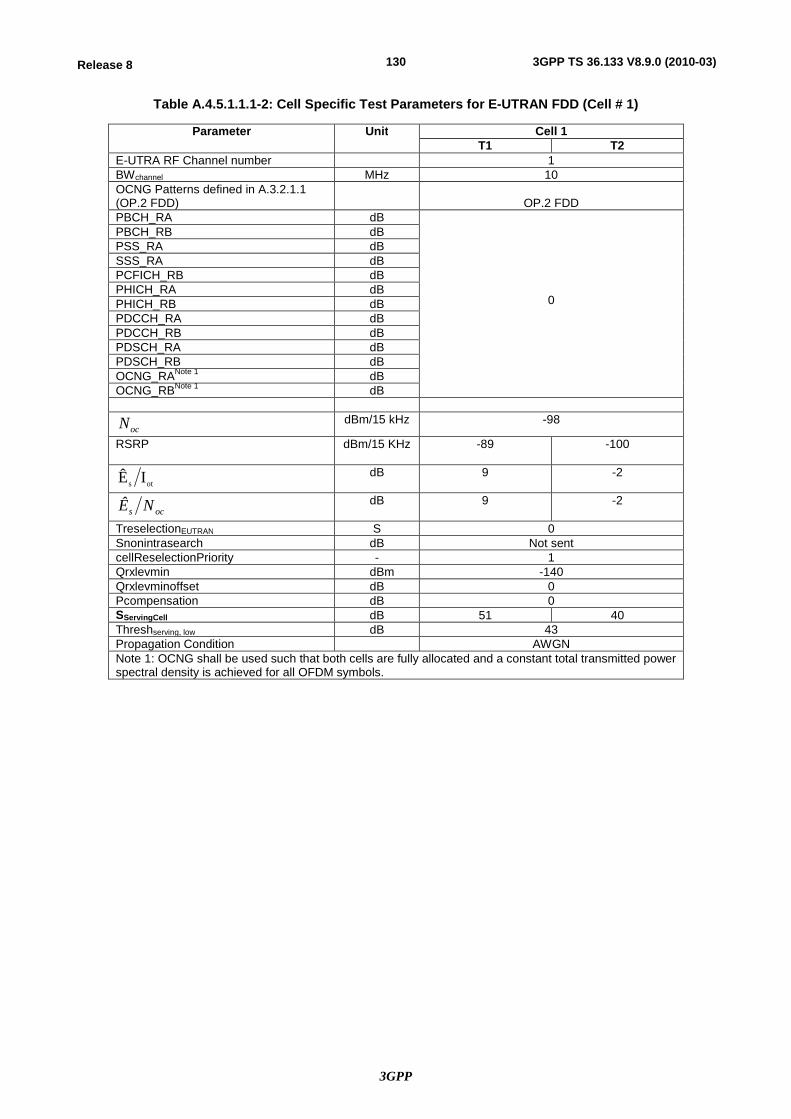
3GPP
130Release 8 3GPP TS 36.133 V8.9.0 (2010-03)
Table A.4.5.1.1.1-2: Cell Specific Test Parameters for E-UTRAN FDD (Cell # 1)
Parameter Unit Cell 1 T1 T2
E-UTRA RF Channel number 1 BWchannel MHz 10 OCNG Patterns defined in A.3.2.1.1 (OP.2 FDD)
OP.2 FDD
PBCH_RA dB
0
PBCH_RB dB PSS_RA dB SSS_RA dB PCFICH_RB dB PHICH_RA dB PHICH_RB dB PDCCH_RA dB PDCCH_RB dB PDSCH_RA dB PDSCH_RB dB OCNG_RANote 1 dB OCNG_RBNote 1 dB
ocN dBm/15 kHz -98
RSRP dBm/15 KHz -89 -100
ots IÊ dB 9 -2
ocs NÊ dB 9 -2
TreselectionEUTRAN S 0 Snonintrasearch dB Not sent cellReselectionPriority - 1 Qrxlevmin dBm -140 Qrxlevminoffset dB 0 Pcompensation dB 0 SServingCell dB 51 40 Threshserving, low dB 43 Propagation Condition AWGN Note 1: OCNG shall be used such that both cells are fully allocated and a constant total transmitted power spectral density is achieved for all OFDM symbols.
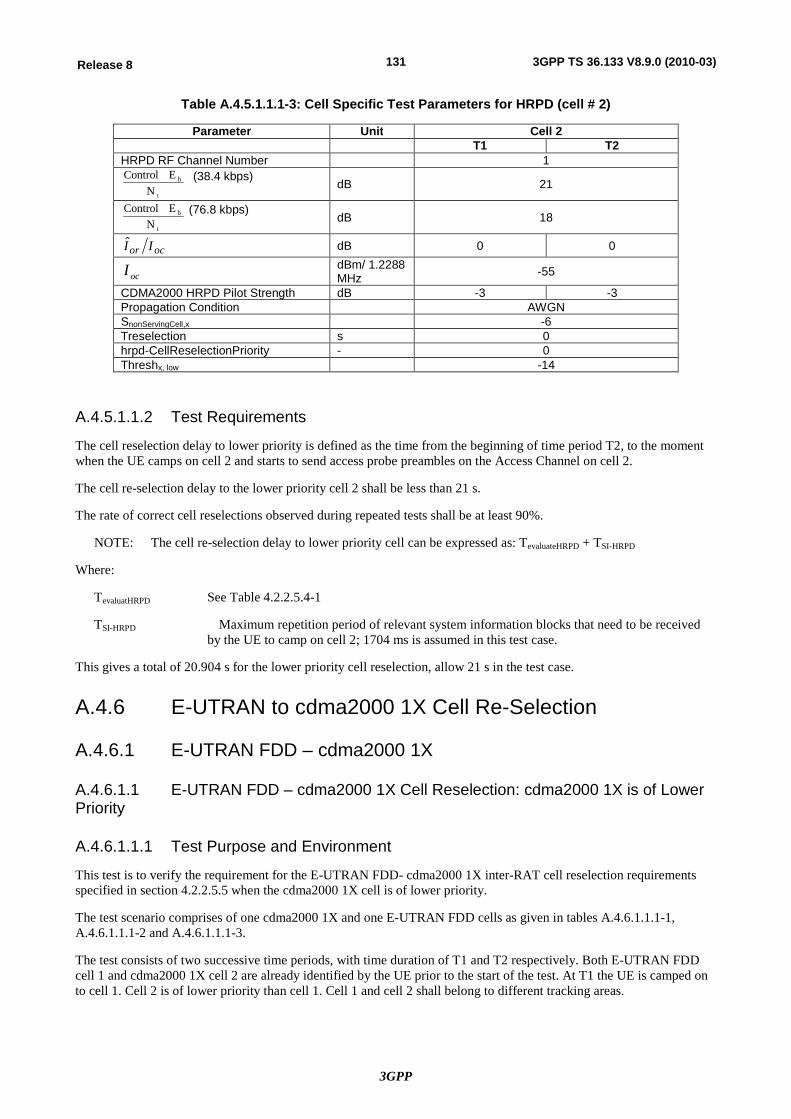
3GPP
131Release 8 3GPP TS 36.133 V8.9.0 (2010-03)
Table A.4.5.1.1.1-3: Cell Specific Test Parameters for HRPD (cell # 2)
Parameter Unit Cell 2 T1 T2
HRPD RF Channel Number 1
t
b
NE Control (38.4 kbps)
dB 21
t
b
NE Control (76.8 kbps)
dB 18
ocor II dB 0 0
ocI dBm/ 1.2288 MHz -55
CDMA2000 HRPD Pilot Strength dB -3 -3 Propagation Condition AWGN SnonServingCell,x -6 Treselection s 0 hrpd-CellReselectionPriority - 0 Threshx, low -14
A.4.5.1.1.2 Test Requirements
The cell reselection delay to lower priority is defined as the time from the beginning of time period T2, to the moment when the UE camps on cell 2 and starts to send access probe preambles on the Access Channel on cell 2.
The cell re-selection delay to the lower priority cell 2 shall be less than 21 s.
The rate of correct cell reselections observed during repeated tests shall be at least 90%.
NOTE: The cell re-selection delay to lower priority cell can be expressed as: TevaluateHRPD + TSI-HRPD
Where:
TevaluatHRPD See Table 4.2.2.5.4-1
TSI-HRPD Maximum repetition period of relevant system information blocks that need to be received by the UE to camp on cell 2; 1704 ms is assumed in this test case.
This gives a total of 20.904 s for the lower priority cell reselection, allow 21 s in the test case.
A.4.6 E-UTRAN to cdma2000 1X Cell Re-Selection
A.4.6.1 E-UTRAN FDD – cdma2000 1X
A.4.6.1.1 E-UTRAN FDD – cdma2000 1X Cell Reselection: cdma2000 1X is of Lower Priority
A.4.6.1.1.1 Test Purpose and Environment
This test is to verify the requirement for the E-UTRAN FDD- cdma2000 1X inter-RAT cell reselection requirements specified in section 4.2.2.5.5 when the cdma2000 1X cell is of lower priority.
The test scenario comprises of one cdma2000 1X and one E-UTRAN FDD cells as given in tables A.4.6.1.1.1-1, A.4.6.1.1.1-2 and A.4.6.1.1.1-3.
The test consists of two successive time periods, with time duration of T1 and T2 respectively. Both E-UTRAN FDD cell 1 and cdma2000 1X cell 2 are already identified by the UE prior to the start of the test. At T1 the UE is camped on to cell 1. Cell 2 is of lower priority than cell 1. Cell 1 and cell 2 shall belong to different tracking areas.
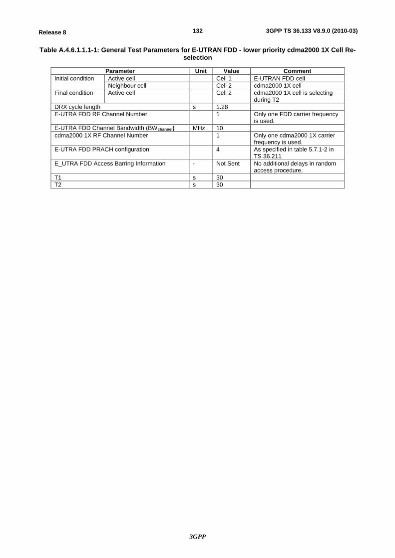
3GPP
132Release 8 3GPP TS 36.133 V8.9.0 (2010-03)
Table A.4.6.1.1.1-1: General Test Parameters for E-UTRAN FDD - lower priority cdma2000 1X Cell Re-selection
Parameter Unit Value Comment Initial condition Active cell Cell 1 E-UTRAN FDD cell
Neighbour cell Cell 2 cdma2000 1X cell Final condition Active cell Cell 2 cdma2000 1X cell is selecting
during T2 DRX cycle length s 1.28 E-UTRA FDD RF Channel Number 1 Only one FDD carrier frequency
is used. E-UTRA FDD Channel Bandwidth (BWchannel) MHz 10 cdma2000 1X RF Channel Number 1 Only one cdma2000 1X carrier
frequency is used. E-UTRA FDD PRACH configuration 4 As specified in table 5.7.1-2 in
TS 36.211 E_UTRA FDD Access Barring Information - Not Sent No additional delays in random
access procedure. T1 s 30 T2 s 30
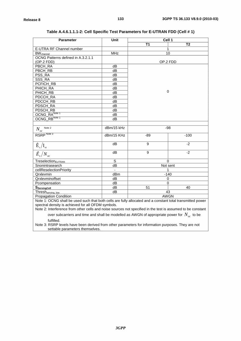
3GPP
133Release 8 3GPP TS 36.133 V8.9.0 (2010-03)
Table A.4.6.1.1.1-2: Cell Specific Test Parameters for E-UTRAN FDD (Cell # 1)
Parameter Unit Cell 1 T1 T2
E-UTRA RF Channel number 1 BWchannel MHz 10 OCNG Patterns defined in A.3.2.1.1 (OP.2 FDD)
OP.2 FDD
PBCH_RA dB
0
PBCH_RB dB PSS_RA dB SSS_RA dB PCFICH_RB dB PHICH_RA dB PHICH_RB dB PDCCH_RA dB PDCCH_RB dB PDSCH_RA dB PDSCH_RB dB OCNG_RANote 1 dB OCNG_RBNote 1 dB
ocN Note 2 dBm/15 kHz -98
RSRP Note 3 dBm/15 KHz -89 -100
ots IÊ dB 9 -2
ocs NÊ dB 9 -2
TreselectionEUTRAN S 0 Snonintrasearch dB Not sent cellReselectionPriority - 1 Qrxlevmin dBm -140 Qrxlevminoffset dB 0 Pcompensation dB 0 SServingCell dB 51 40 Threshserving, low dB 43 Propagation Condition AWGN Note 1: OCNG shall be used such that both cells are fully allocated and a constant total transmitted power spectral density is achieved for all OFDM symbols. Note 2: Interference from other cells and noise sources not specified in the test is assumed to be constant
over subcarriers and time and shall be modelled as AWGN of appropriate power for ocN to be fulfilled.
Note 3: RSRP levels have been derived from other parameters for information purposes. They are not settable parameters themselves.
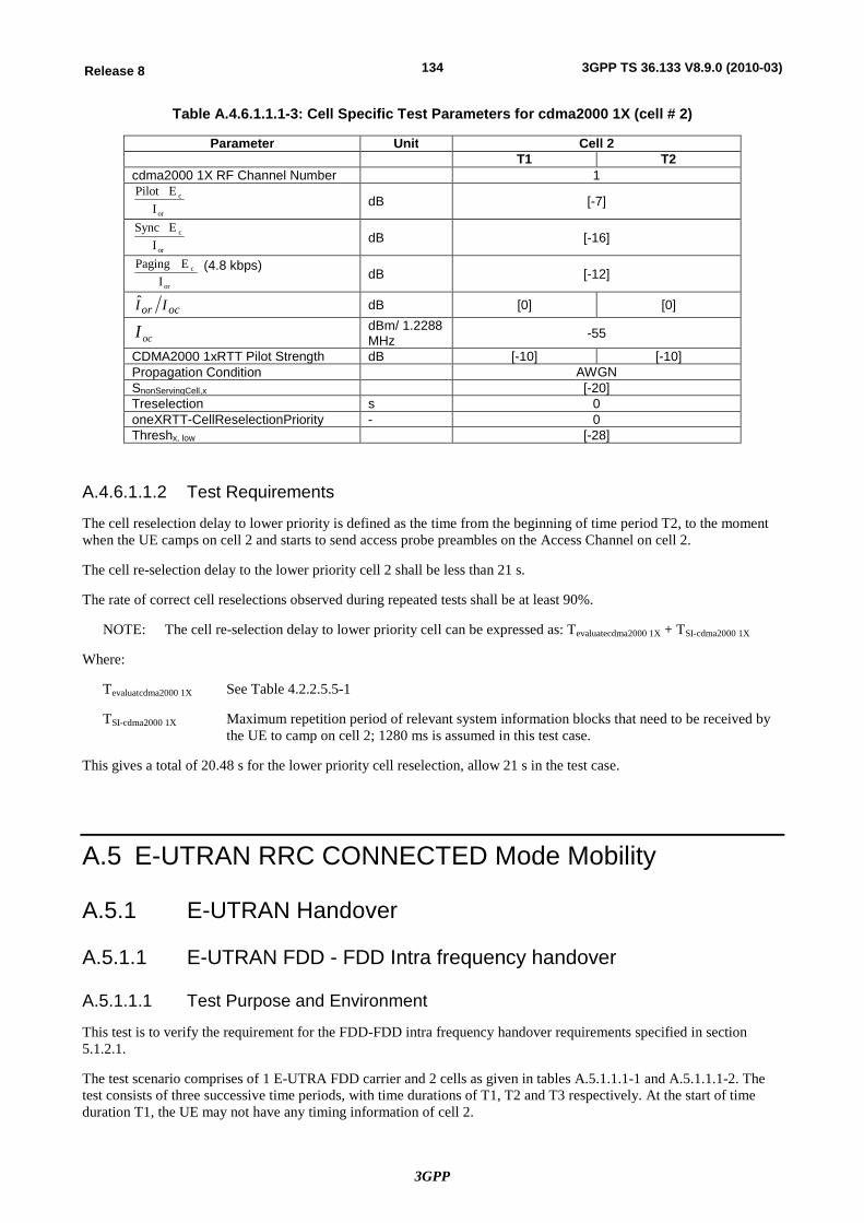
3GPP
134Release 8 3GPP TS 36.133 V8.9.0 (2010-03)
Table A.4.6.1.1.1-3: Cell Specific Test Parameters for cdma2000 1X (cell # 2)
Parameter Unit Cell 2 T1 T2
cdma2000 1X RF Channel Number 1
or
c
IEPilot
dB [-7]
or
c
IE Sync
dB [-16]
or
c
IE Paging (4.8 kbps)
dB [-12]
ocor II dB [0] [0]
ocI dBm/ 1.2288 MHz -55
CDMA2000 1xRTT Pilot Strength dB [-10] [-10] Propagation Condition AWGN SnonServingCell,x [-20] Treselection s 0 oneXRTT-CellReselectionPriority - 0 Threshx, low [-28]
A.4.6.1.1.2 Test Requirements
The cell reselection delay to lower priority is defined as the time from the beginning of time period T2, to the moment when the UE camps on cell 2 and starts to send access probe preambles on the Access Channel on cell 2.
The cell re-selection delay to the lower priority cell 2 shall be less than 21 s.
The rate of correct cell reselections observed during repeated tests shall be at least 90%.
NOTE: The cell re-selection delay to lower priority cell can be expressed as: Tevaluatecdma2000 1X + TSI-cdma2000 1X
Where:
Tevaluatcdma2000 1X See Table 4.2.2.5.5-1
TSI-cdma2000 1X Maximum repetition period of relevant system information blocks that need to be received by the UE to camp on cell 2; 1280 ms is assumed in this test case.
This gives a total of 20.48 s for the lower priority cell reselection, allow 21 s in the test case.
A.5 E-UTRAN RRC CONNECTED Mode Mobility
A.5.1 E-UTRAN Handover
A.5.1.1 E-UTRAN FDD - FDD Intra frequency handover
A.5.1.1.1 Test Purpose and Environment
This test is to verify the requirement for the FDD-FDD intra frequency handover requirements specified in section 5.1.2.1.
The test scenario comprises of 1 E-UTRA FDD carrier and 2 cells as given in tables A.5.1.1.1-1 and A.5.1.1.1-2. The test consists of three successive time periods, with time durations of T1, T2 and T3 respectively. At the start of time duration T1, the UE may not have any timing information of cell 2.
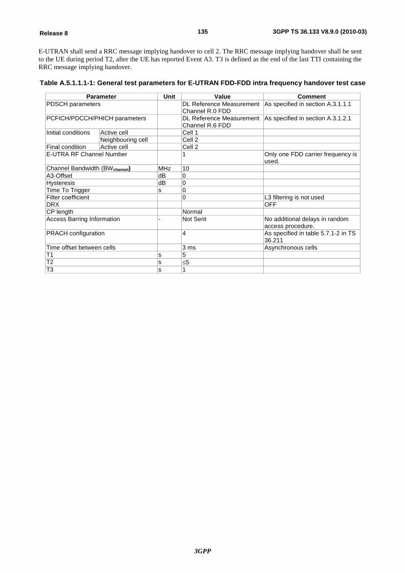
3GPP
135Release 8 3GPP TS 36.133 V8.9.0 (2010-03)
E-UTRAN shall send a RRC message implying handover to cell 2. The RRC message implying handover shall be sent to the UE during period T2, after the UE has reported Event A3. T3 is defined as the end of the last TTI containing the RRC message implying handover.
Table A.5.1.1.1-1: General test parameters for E-UTRAN FDD-FDD intra frequency handover test case
Parameter Unit Value Comment PDSCH parameters DL Reference Measurement
Channel R.0 FDD As specified in section A.3.1.1.1
PCFICH/PDCCH/PHICH parameters DL Reference Measurement Channel R.6 FDD
As specified in section A.3.1.2.1
Initial conditions Active cell Cell 1 Neighbouring cell Cell 2
Final condition Active cell Cell 2 E-UTRA RF Channel Number 1 Only one FDD carrier frequency is
used. Channel Bandwidth (BWchannel) MHz 10 A3-Offset dB 0 Hysteresis dB 0 Time To Trigger s 0 Filter coefficient 0 L3 filtering is not used DRX OFF CP length Normal Access Barring Information - Not Sent No additional delays in random
access procedure. PRACH configuration 4 As specified in table 5.7.1-2 in TS
36.211 Time offset between cells 3 ms Asynchronous cells T1 s 5 T2 s £5 T3 s 1
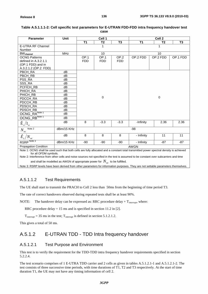
3GPP
136Release 8 3GPP TS 36.133 V8.9.0 (2010-03)
Table A.5.1.1.1-2: Cell specific test parameters for E-UTRAN FDD-FDD intra frequency handover test case
Parameter Unit Cell 1 Cell 2 T1 T2 T3 T1 T2 T3
E-UTRA RF Channel Number
1 1
BWchannel MHz 10 10 OCNG Patterns defined in A.3.2.1.1 (OP.1 FDD) and in A.3.2.1.2 (OP.2 FDD)
OP.1 FDD
OP.1 FDD
OP.2 FDD
OP.2 FDD OP.2 FDD OP.1 FDD
PBCH_RA dB
0
0
PBCH_RB dB PSS_RA dB SSS_RA dB PCFICH_RB dB PHICH_RA dB PHICH_RB dB PDCCH_RA dB PDCCH_RB dB PDSCH_RA dB PDSCH_RB dB OCNG_RANote 1 dB OCNG_RBNote 1 dB
ots IÊ dB 8 -3.3 -3.3 -Infinity 2.36 2.36
ocN Note 2 dBm/15 KHz -98
ocs NÊ dB 8 8 8 - Infinity 11 11
RSRP Note 3 dBm/15 KHz -90 -90 -90 - Infinity -87 -87 Propagation Condition AWGN Note 1: OCNG shall be used such that both cells are fully allocated and a constant total transmitted power spectral density is achieved
for all OFDM symbols. Note 2: Interference from other cells and noise sources not specified in the test is assumed to be constant over subcarriers and time
and shall be modelled as AWGN of appropriate power for ocN to be fulfilled. Note 3: RSRP levels have been derived from other parameters for information purposes. They are not settable parameters themselves.
A.5.1.1.2 Test Requirements
The UE shall start to transmit the PRACH to Cell 2 less than 50ms from the beginning of time period T3.
The rate of correct handovers observed during repeated tests shall be at least 90%.
NOTE: The handover delay can be expressed as: RRC procedure delay + Tinterrupt, where:
RRC procedure delay = 15 ms and is specified in section 11.2 in [2].
Tinterrupt = 35 ms in the test; Tinterrupt is defined in section 5.1.2.1.2.
This gives a total of 50 ms.
A.5.1.2 E-UTRAN TDD - TDD Intra frequency handover
A.5.1.2.1 Test Purpose and Environment
This test is to verify the requirement for the TDD-TDD intra frequency handover requirements specified in section 5.2.2.4.
The test scenario comprises of 1 E-UTRA TDD carrier and 2 cells as given in tables A.5.1.2.1-1 and A.5.1.2.1-2. The test consists of three successive time periods, with time durations of T1, T2 and T3 respectively. At the start of time duration T1, the UE may not have any timing information of cell 2.
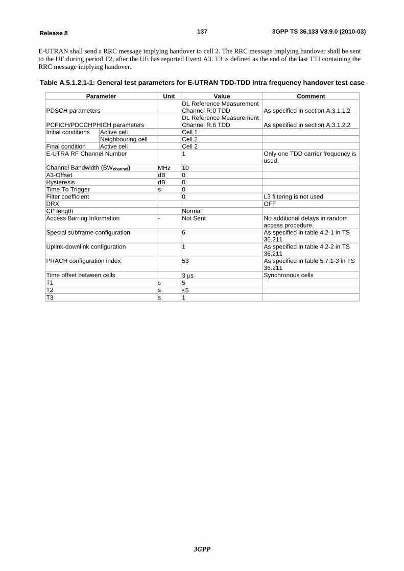
3GPP
137Release 8 3GPP TS 36.133 V8.9.0 (2010-03)
E-UTRAN shall send a RRC message implying handover to cell 2. The RRC message implying handover shall be sent to the UE during period T2, after the UE has reported Event A3. T3 is defined as the end of the last TTI containing the RRC message implying handover.
Table A.5.1.2.1-1: General test parameters for E-UTRAN TDD-TDD Intra frequency handover test case
Parameter Unit Value Comment PDSCH parameters
DL Reference Measurement Channel R.0 TDD
As specified in section A.3.1.1.2
PCFICH/PDCCHPHICH parameters
DL Reference Measurement Channel R.6 TDD
As specified in section A.3.1.2.2
Initial conditions Active cell Cell 1 Neighbouring cell Cell 2
Final condition Active cell Cell 2 E-UTRA RF Channel Number 1 Only one TDD carrier frequency is
used. Channel Bandwidth (BWchannel) MHz 10 A3-Offset dB 0 Hysteresis dB 0 Time To Trigger s 0 Filter coefficient 0 L3 filtering is not used DRX OFF CP length Normal Access Barring Information - Not Sent No additional delays in random
access procedure. Special subframe configuration 6 As specified in table 4.2-1 in TS
36.211 Uplink-downlink configuration 1 As specified in table 4.2-2 in TS
36.211 PRACH configuration index 53 As specified in table 5.7.1-3 in TS
36.211 Time offset between cells 3 ms Synchronous cells T1 s 5 T2 s £5 T3 s 1
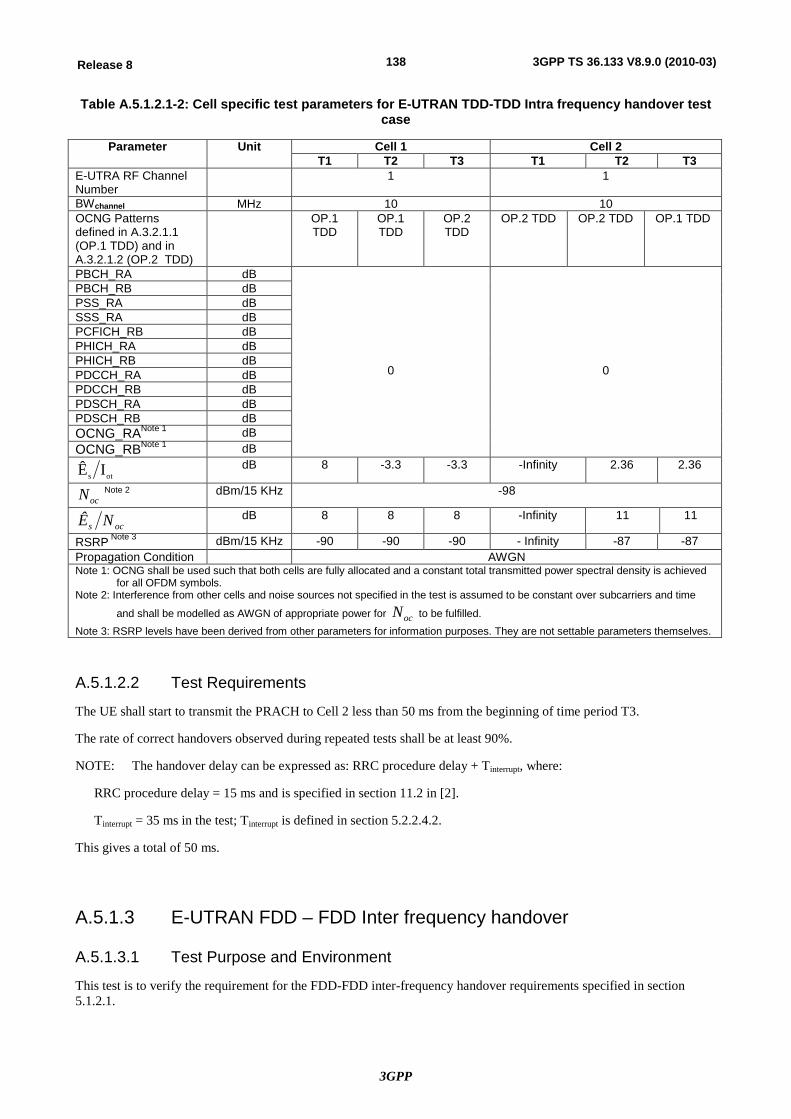
3GPP
138Release 8 3GPP TS 36.133 V8.9.0 (2010-03)
Table A.5.1.2.1-2: Cell specific test parameters for E-UTRAN TDD-TDD Intra frequency handover test case
Parameter Unit Cell 1 Cell 2 T1 T2 T3 T1 T2 T3
E-UTRA RF Channel Number
1 1
BWchannel MHz 10 10 OCNG Patterns defined in A.3.2.1.1 (OP.1 TDD) and in A.3.2.1.2 (OP.2 TDD)
OP.1 TDD
OP.1 TDD
OP.2 TDD
OP.2 TDD OP.2 TDD OP.1 TDD
PBCH_RA dB
0
0
PBCH_RB dB PSS_RA dB SSS_RA dB PCFICH_RB dB PHICH_RA dB PHICH_RB dB PDCCH_RA dB PDCCH_RB dB PDSCH_RA dB PDSCH_RB dB OCNG_RANote 1 dB OCNG_RBNote 1 dB
ots IÊ dB 8 -3.3 -3.3 -Infinity 2.36 2.36
ocN Note 2 dBm/15 KHz -98
ocs NÊ dB 8 8 8 -Infinity 11 11
RSRP Note 3 dBm/15 KHz -90 -90 -90 - Infinity -87 -87 Propagation Condition AWGN Note 1: OCNG shall be used such that both cells are fully allocated and a constant total transmitted power spectral density is achieved
for all OFDM symbols. Note 2: Interference from other cells and noise sources not specified in the test is assumed to be constant over subcarriers and time
and shall be modelled as AWGN of appropriate power for ocN to be fulfilled. Note 3: RSRP levels have been derived from other parameters for information purposes. They are not settable parameters themselves.
A.5.1.2.2 Test Requirements
The UE shall start to transmit the PRACH to Cell 2 less than 50 ms from the beginning of time period T3.
The rate of correct handovers observed during repeated tests shall be at least 90%.
NOTE: The handover delay can be expressed as: RRC procedure delay + Tinterrupt, where:
RRC procedure delay = 15 ms and is specified in section 11.2 in [2].
Tinterrupt = 35 ms in the test; Tinterrupt is defined in section 5.2.2.4.2.
This gives a total of 50 ms.
A.5.1.3 E-UTRAN FDD – FDD Inter frequency handover
A.5.1.3.1 Test Purpose and Environment
This test is to verify the requirement for the FDD-FDD inter-frequency handover requirements specified in section 5.1.2.1.
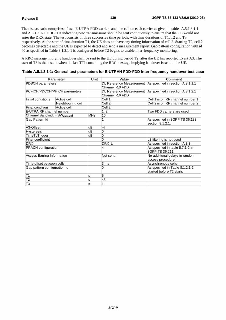
3GPP
139Release 8 3GPP TS 36.133 V8.9.0 (2010-03)
The test scenario comprises of two E-UTRA FDD carriers and one cell on each carrier as given in tables A.5.1.3.1-1 and A.5.1.3.1-2. PDCCHs indicating new transmissions should be sent continuously to ensure that the UE would not enter the DRX state. The test consists of three successive time periods, with time durations of T1, T2 and T3 respectively. At the start of time duration T1, the UE does not have any timing information of cell 2. Starting T2, cell 2 becomes detectable and the UE is expected to detect and send a measurement report. Gap pattern configuration with id #0 as specified in Table 8.1.2.1-1 is configured before T2 begins to enable inter-frequency monitoring.
A RRC message implying handover shall be sent to the UE during period T2, after the UE has reported Event A3. The start of T3 is the instant when the last TTI containing the RRC message implying handover is sent to the UE.
Table A.5.1.3.1-1: General test parameters for E-UTRAN FDD-FDD Inter frequency handover test case
Parameter Unit Value Comment PDSCH parameters DL Reference Measurement
Channel R.0 FDD As specified in section A.3.1.1.1
PCFICH/PDCCH/PHICH parameters DL Reference Measurement Channel R.6 FDD
As specified in section A.3.1.2.1
Initial conditions Active cell Cell 1 Cell 1 is on RF channel number 1 Neighbouring cell Cell 2 Cell 2 is on RF channel number 2
Final condition Active cell Cell 2 E-UTRA RF channel number 1, 2 Two FDD carriers are used Channel Bandwidth (BWchannel) MHz 10 Gap Pattern Id 1 As specified in 3GPP TS 36.133
section 8.1.2.1. A3-Offset dB -4 Hysteresis dB 0 TimeToTrigger dB 0 Filter coefficient 0 L3 filtering is not used DRX DRX_L As specified in section A.3.3 PRACH configuration 4 As specified in table 5.7.1-2 in
3GPP TS 36.211 Access Barring Information - Not sent No additional delays in random
access procedure Time offset between cells 3 ms Asynchronous cells Gap pattern configuration Id 0 As specified in Table 8.1.2.1-1
started before T2 starts T1 s 5 T2 s £5 T3 s 1
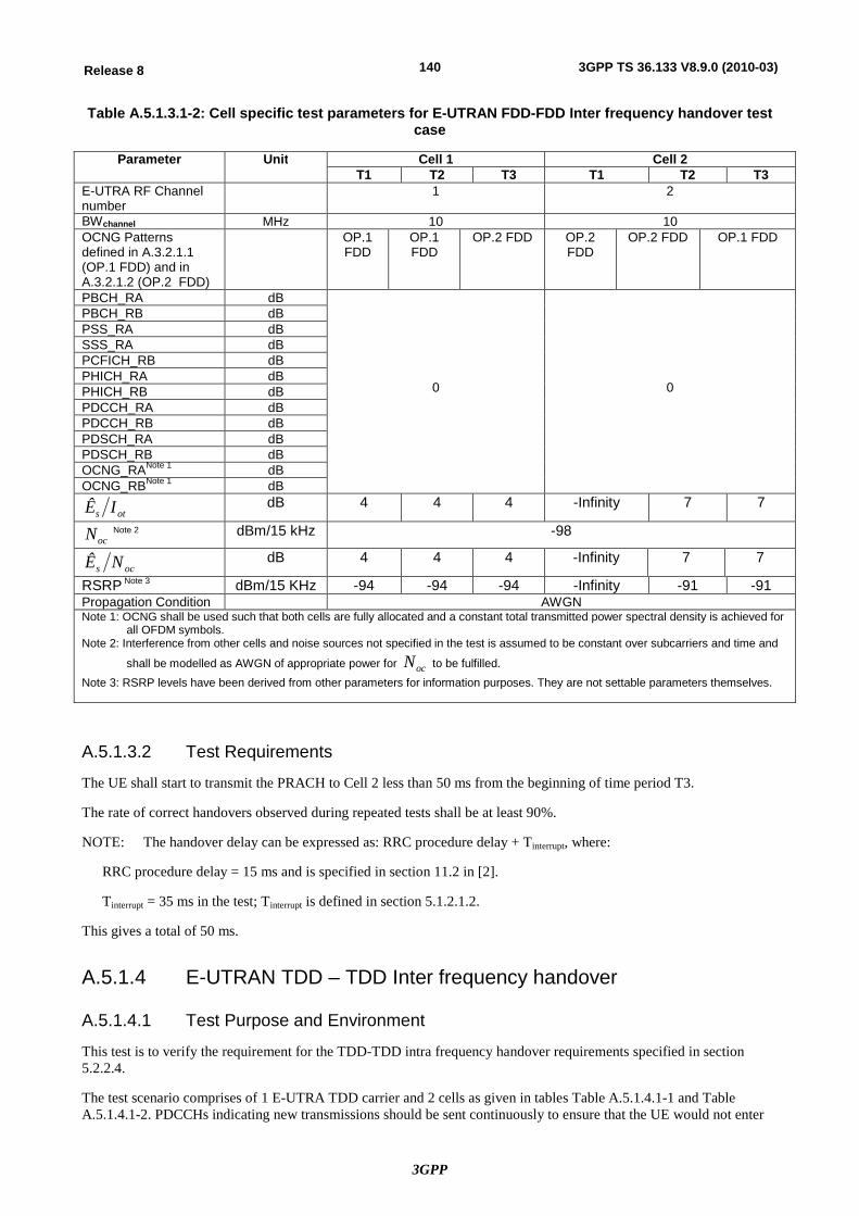
3GPP
140Release 8 3GPP TS 36.133 V8.9.0 (2010-03)
Table A.5.1.3.1-2: Cell specific test parameters for E-UTRAN FDD-FDD Inter frequency handover test case
Parameter Unit Cell 1 Cell 2 T1 T2 T3 T1 T2 T3
E-UTRA RF Channel number
1 2
BWchannel MHz 10 10 OCNG Patterns defined in A.3.2.1.1 (OP.1 FDD) and in A.3.2.1.2 (OP.2 FDD)
OP.1 FDD
OP.1 FDD
OP.2 FDD OP.2 FDD
OP.2 FDD OP.1 FDD
PBCH_RA dB
0
0
PBCH_RB dB PSS_RA dB SSS_RA dB PCFICH_RB dB PHICH_RA dB PHICH_RB dB PDCCH_RA dB PDCCH_RB dB PDSCH_RA dB PDSCH_RB dB OCNG_RANote 1 dB OCNG_RBNote 1 dB
ots IÊ dB 4 4 4 -Infinity 7 7
ocN Note 2 dBm/15 kHz -98
ocs NÊ dB 4 4 4 -Infinity 7 7
RSRP Note 3 dBm/15 KHz -94 -94 -94 -Infinity -91 -91 Propagation Condition AWGN Note 1: OCNG shall be used such that both cells are fully allocated and a constant total transmitted power spectral density is achieved for
all OFDM symbols. Note 2: Interference from other cells and noise sources not specified in the test is assumed to be constant over subcarriers and time and
shall be modelled as AWGN of appropriate power for ocN to be fulfilled. Note 3: RSRP levels have been derived from other parameters for information purposes. They are not settable parameters themselves.
A.5.1.3.2 Test Requirements
The UE shall start to transmit the PRACH to Cell 2 less than 50 ms from the beginning of time period T3.
The rate of correct handovers observed during repeated tests shall be at least 90%.
NOTE: The handover delay can be expressed as: RRC procedure delay + Tinterrupt, where:
RRC procedure delay = 15 ms and is specified in section 11.2 in [2].
Tinterrupt = 35 ms in the test; Tinterrupt is defined in section 5.1.2.1.2.
This gives a total of 50 ms.
A.5.1.4 E-UTRAN TDD – TDD Inter frequency handover
A.5.1.4.1 Test Purpose and Environment
This test is to verify the requirement for the TDD-TDD intra frequency handover requirements specified in section 5.2.2.4.
The test scenario comprises of 1 E-UTRA TDD carrier and 2 cells as given in tables Table A.5.1.4.1-1 and Table A.5.1.4.1-2. PDCCHs indicating new transmissions should be sent continuously to ensure that the UE would not enter
3GPP
141Release 8 3GPP TS 36.133 V8.9.0 (2010-03)
the DRX state. The test consists of three successive time periods, with time durations of T1, T2 and T3 respectively. At the start of time duration T1, the UE may not have any timing information of cell 2.
E-UTRAN shall send a RRC message implying handover to cell 2. The RRC message implying handover shall be sent to the UE during period T2, after the UE has reported Event A3.
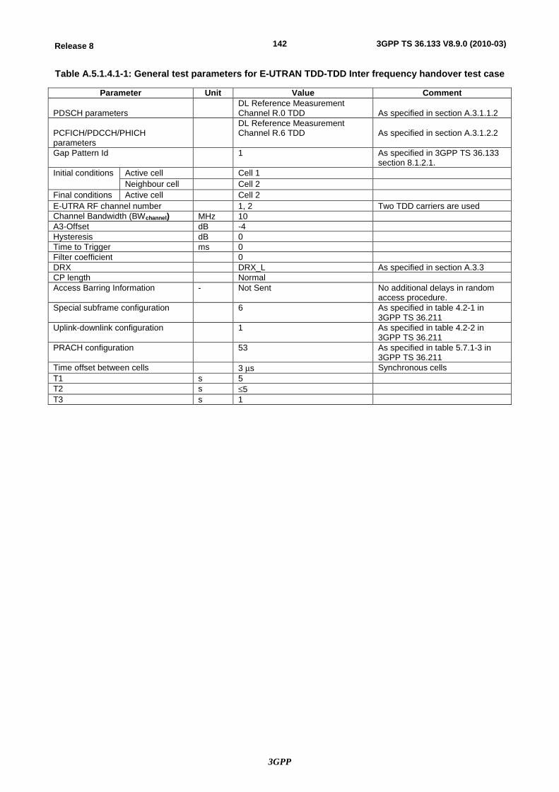
3GPP
142Release 8 3GPP TS 36.133 V8.9.0 (2010-03)
Table A.5.1.4.1-1: General test parameters for E-UTRAN TDD-TDD Inter frequency handover test case
Parameter Unit Value Comment PDSCH parameters
DL Reference Measurement Channel R.0 TDD
As specified in section A.3.1.1.2
PCFICH/PDCCH/PHICH parameters
DL Reference Measurement Channel R.6 TDD
As specified in section A.3.1.2.2
Gap Pattern Id 1 As specified in 3GPP TS 36.133 section 8.1.2.1.
Initial conditions Active cell Cell 1 Neighbour cell Cell 2
Final conditions Active cell Cell 2 E-UTRA RF channel number 1, 2 Two TDD carriers are used Channel Bandwidth (BWchannel) MHz 10 A3-Offset dB -4 Hysteresis dB 0 Time to Trigger ms 0 Filter coefficient 0 DRX DRX_L As specified in section A.3.3 CP length Normal Access Barring Information - Not Sent No additional delays in random
access procedure. Special subframe configuration 6 As specified in table 4.2-1 in
3GPP TS 36.211 Uplink-downlink configuration 1 As specified in table 4.2-2 in
3GPP TS 36.211 PRACH configuration 53 As specified in table 5.7.1-3 in
3GPP TS 36.211 Time offset between cells 3 ms Synchronous cells T1 s 5 T2 s £5 T3 s 1
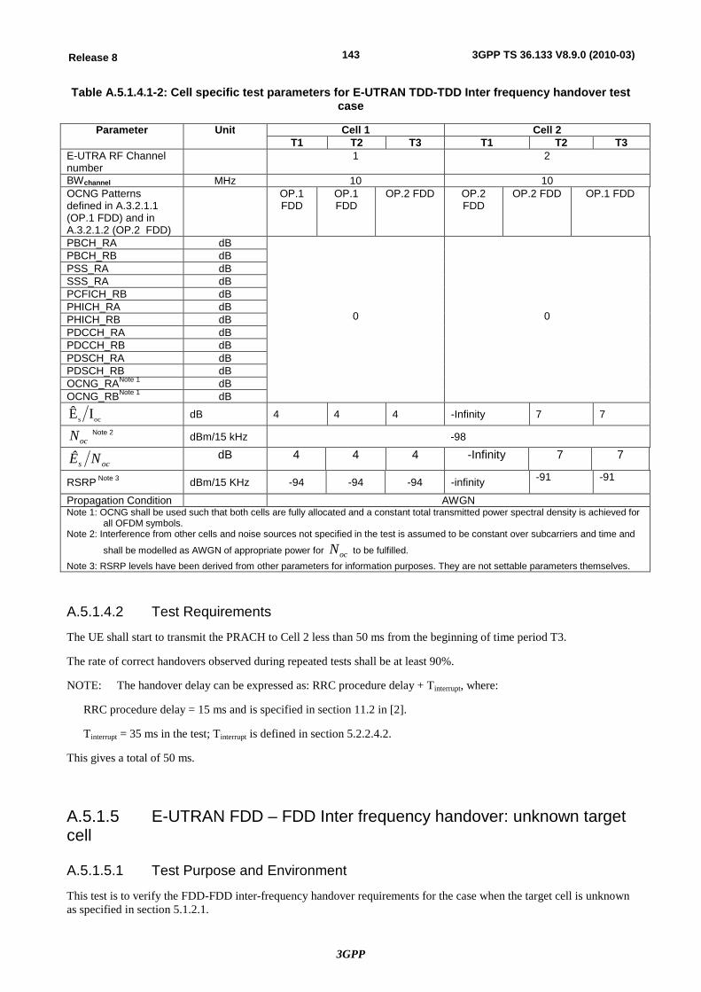
3GPP
143Release 8 3GPP TS 36.133 V8.9.0 (2010-03)
Table A.5.1.4.1-2: Cell specific test parameters for E-UTRAN TDD-TDD Inter frequency handover test case
Parameter Unit Cell 1 Cell 2 T1 T2 T3 T1 T2 T3
E-UTRA RF Channel number
1 2
BWchannel MHz 10 10 OCNG Patterns defined in A.3.2.1.1 (OP.1 FDD) and in A.3.2.1.2 (OP.2 FDD)
OP.1 FDD
OP.1 FDD
OP.2 FDD OP.2 FDD
OP.2 FDD OP.1 FDD
PBCH_RA dB
0
0
PBCH_RB dB PSS_RA dB SSS_RA dB PCFICH_RB dB PHICH_RA dB PHICH_RB dB PDCCH_RA dB PDCCH_RB dB PDSCH_RA dB PDSCH_RB dB OCNG_RANote 1 dB OCNG_RBNote 1 dB
ocs IÊ dB 4 4 4 -Infinity 7 7
ocN Note 2 dBm/15 kHz -98
ocs NÊ dB 4 4 4 -Infinity 7 7
RSRP Note 3 dBm/15 KHz -94 -94 -94 -infinity -91 -91
Propagation Condition AWGN Note 1: OCNG shall be used such that both cells are fully allocated and a constant total transmitted power spectral density is achieved for
all OFDM symbols. Note 2: Interference from other cells and noise sources not specified in the test is assumed to be constant over subcarriers and time and
shall be modelled as AWGN of appropriate power for ocN to be fulfilled. Note 3: RSRP levels have been derived from other parameters for information purposes. They are not settable parameters themselves.
A.5.1.4.2 Test Requirements
The UE shall start to transmit the PRACH to Cell 2 less than 50 ms from the beginning of time period T3.
The rate of correct handovers observed during repeated tests shall be at least 90%.
NOTE: The handover delay can be expressed as: RRC procedure delay + Tinterrupt, where:
RRC procedure delay = 15 ms and is specified in section 11.2 in [2].
Tinterrupt = 35 ms in the test; Tinterrupt is defined in section 5.2.2.4.2.
This gives a total of 50 ms.
A.5.1.5 E-UTRAN FDD – FDD Inter frequency handover: unknown target cell
A.5.1.5.1 Test Purpose and Environment
This test is to verify the FDD-FDD inter-frequency handover requirements for the case when the target cell is unknown as specified in section 5.1.2.1.
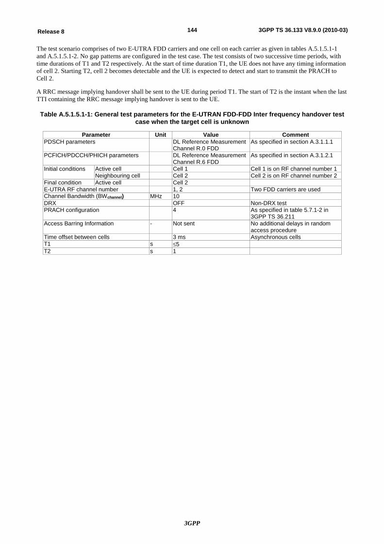
3GPP
144Release 8 3GPP TS 36.133 V8.9.0 (2010-03)
The test scenario comprises of two E-UTRA FDD carriers and one cell on each carrier as given in tables A.5.1.5.1-1 and A.5.1.5.1-2. No gap patterns are configured in the test case. The test consists of two successive time periods, with time durations of T1 and T2 respectively. At the start of time duration T1, the UE does not have any timing information of cell 2. Starting T2, cell 2 becomes detectable and the UE is expected to detect and start to transmit the PRACH to Cell 2.
A RRC message implying handover shall be sent to the UE during period T1. The start of T2 is the instant when the last TTI containing the RRC message implying handover is sent to the UE.
Table A.5.1.5.1-1: General test parameters for the E-UTRAN FDD-FDD Inter frequency handover test case when the target cell is unknown
Parameter Unit Value Comment PDSCH parameters DL Reference Measurement
Channel R.0 FDD As specified in section A.3.1.1.1
PCFICH/PDCCH/PHICH parameters DL Reference Measurement Channel R.6 FDD
As specified in section A.3.1.2.1
Initial conditions Active cell Cell 1 Cell 1 is on RF channel number 1 Neighbouring cell Cell 2 Cell 2 is on RF channel number 2
Final condition Active cell Cell 2 E-UTRA RF channel number 1, 2 Two FDD carriers are used Channel Bandwidth (BWchannel) MHz 10 DRX OFF Non-DRX test PRACH configuration 4 As specified in table 5.7.1-2 in
3GPP TS 36.211 Access Barring Information - Not sent No additional delays in random
access procedure Time offset between cells 3 ms Asynchronous cells T1 s £5 T2 s 1
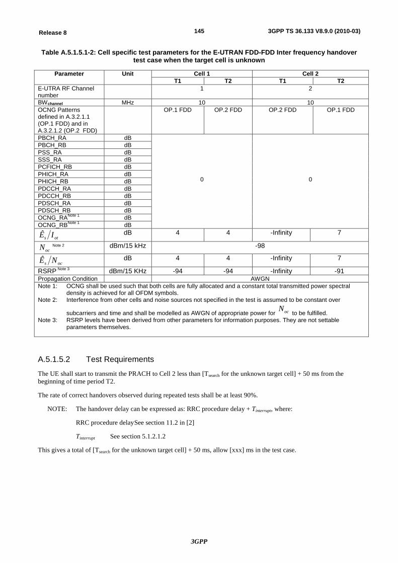
3GPP
145Release 8 3GPP TS 36.133 V8.9.0 (2010-03)
Table A.5.1.5.1-2: Cell specific test parameters for the E-UTRAN FDD-FDD Inter frequency handover test case when the target cell is unknown
Parameter Unit Cell 1 Cell 2 T1 T2 T1 T2
E-UTRA RF Channel number
1 2
BWchannel MHz 10 10 OCNG Patterns defined in A.3.2.1.1 (OP.1 FDD) and in A.3.2.1.2 (OP.2 FDD)
OP.1 FDD OP.2 FDD OP.2 FDD OP.1 FDD
PBCH_RA dB
0
0
PBCH_RB dB PSS_RA dB SSS_RA dB PCFICH_RB dB PHICH_RA dB PHICH_RB dB PDCCH_RA dB PDCCH_RB dB PDSCH_RA dB PDSCH_RB dB OCNG_RANote 1 dB OCNG_RBNote 1 dB
ots IÊ dB 4 4 -Infinity 7
ocN Note 2 dBm/15 kHz -98
ocs NÊ dB 4 4 -Infinity 7
RSRP Note 3 dBm/15 KHz -94 -94 -Infinity -91 Propagation Condition AWGN Note 1: OCNG shall be used such that both cells are fully allocated and a constant total transmitted power spectral
density is achieved for all OFDM symbols. Note 2: Interference from other cells and noise sources not specified in the test is assumed to be constant over
subcarriers and time and shall be modelled as AWGN of appropriate power for ocN to be fulfilled.
Note 3: RSRP levels have been derived from other parameters for information purposes. They are not settable parameters themselves.
A.5.1.5.2 Test Requirements
The UE shall start to transmit the PRACH to Cell 2 less than [Tsearch for the unknown target cell] + 50 ms from the beginning of time period T2.
The rate of correct handovers observed during repeated tests shall be at least 90%.
NOTE: The handover delay can be expressed as: RRC procedure delay + Tinterrupt, where:
RRC procedure delay See section 11.2 in [2]
Tinterrupt See section 5.1.2.1.2
This gives a total of [Tsearch for the unknown target cell] + 50 ms, allow [xxx] ms in the test case.
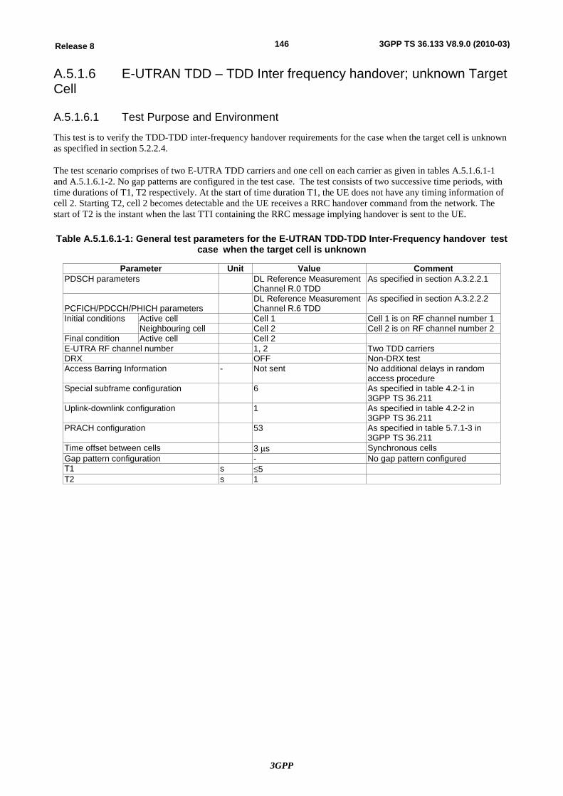
3GPP
146Release 8 3GPP TS 36.133 V8.9.0 (2010-03)
A.5.1.6 E-UTRAN TDD – TDD Inter frequency handover; unknown Target Cell
A.5.1.6.1 Test Purpose and Environment
This test is to verify the TDD-TDD inter-frequency handover requirements for the case when the target cell is unknown as specified in section 5.2.2.4.
The test scenario comprises of two E-UTRA TDD carriers and one cell on each carrier as given in tables A.5.1.6.1-1 and A.5.1.6.1-2. No gap patterns are configured in the test case. The test consists of two successive time periods, with time durations of T1, T2 respectively. At the start of time duration T1, the UE does not have any timing information of cell 2. Starting T2, cell 2 becomes detectable and the UE receives a RRC handover command from the network. The start of T2 is the instant when the last TTI containing the RRC message implying handover is sent to the UE. Table A.5.1.6.1-1: General test parameters for the E-UTRAN TDD-TDD Inter-Frequency handover test
case when the target cell is unknown
Parameter Unit Value Comment PDSCH parameters DL Reference Measurement
Channel R.0 TDD As specified in section A.3.2.2.1
PCFICH/PDCCH/PHICH parameters
DL Reference Measurement Channel R.6 TDD
As specified in section A.3.2.2.2
Initial conditions Active cell Cell 1 Cell 1 is on RF channel number 1 Neighbouring cell Cell 2 Cell 2 is on RF channel number 2
Final condition Active cell Cell 2 E-UTRA RF channel number 1, 2 Two TDD carriers DRX OFF Non-DRX test Access Barring Information - Not sent No additional delays in random
access procedure Special subframe configuration 6 As specified in table 4.2-1 in
3GPP TS 36.211 Uplink-downlink configuration 1 As specified in table 4.2-2 in
3GPP TS 36.211 PRACH configuration 53 As specified in table 5.7.1-3 in
3GPP TS 36.211 Time offset between cells 3 ms Synchronous cells Gap pattern configuration - No gap pattern configured T1 s £5 T2 s 1
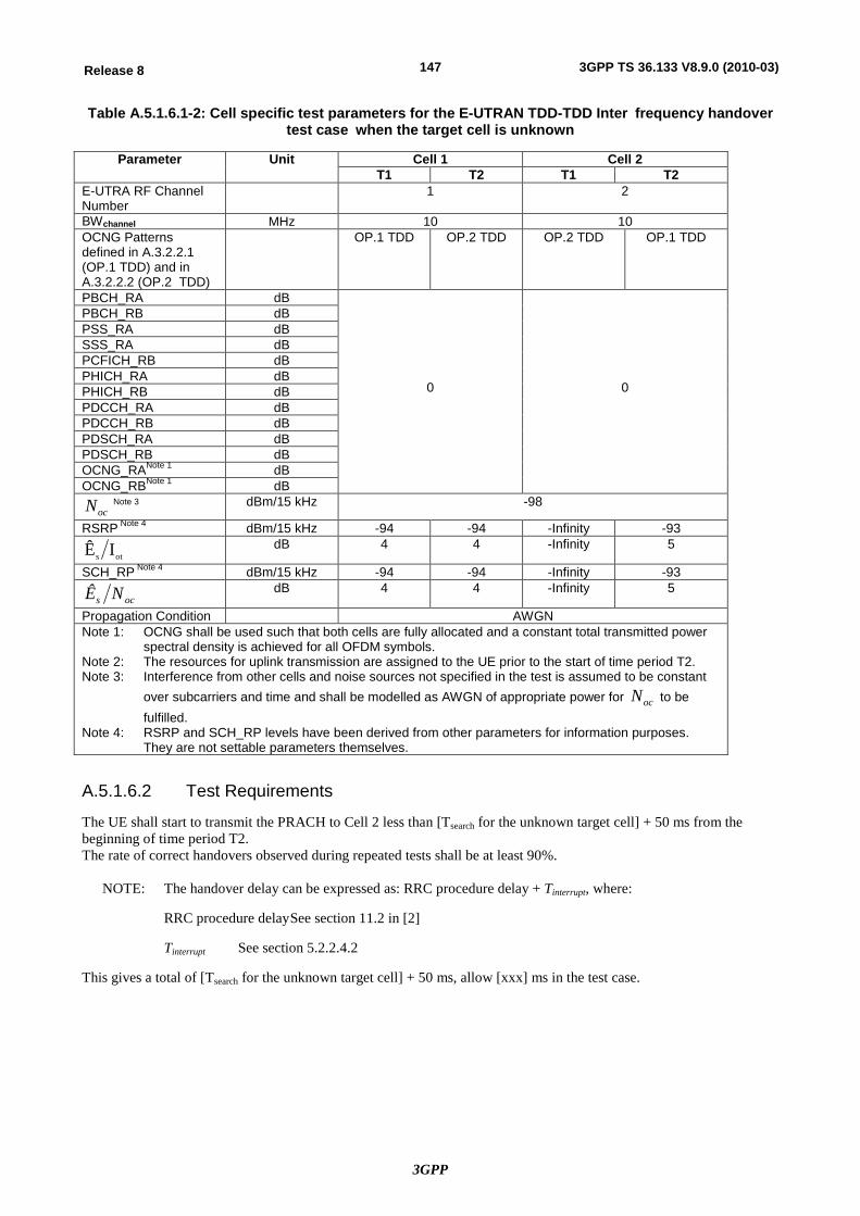
3GPP
147Release 8 3GPP TS 36.133 V8.9.0 (2010-03)
Table A.5.1.6.1-2: Cell specific test parameters for the E-UTRAN TDD-TDD Inter frequency handover test case when the target cell is unknown
Parameter Unit Cell 1 Cell 2 T1 T2 T1 T2
E-UTRA RF Channel Number
1 2
BWchannel MHz 10 10 OCNG Patterns defined in A.3.2.2.1 (OP.1 TDD) and in A.3.2.2.2 (OP.2 TDD)
OP.1 TDD OP.2 TDD OP.2 TDD OP.1 TDD
PBCH_RA dB
0
0
PBCH_RB dB PSS_RA dB SSS_RA dB PCFICH_RB dB PHICH_RA dB PHICH_RB dB PDCCH_RA dB PDCCH_RB dB PDSCH_RA dB PDSCH_RB dB OCNG_RANote 1 dB OCNG_RBNote 1 dB
ocN Note 3 dBm/15 kHz -98
RSRP Note 4 dBm/15 kHz -94 -94 -Infinity -93
ots IÊ dB 4 4 -Infinity 5
SCH_RP Note 4 dBm/15 kHz -94 -94 -Infinity -93
ocs NÊ dB 4 4 -Infinity 5
Propagation Condition AWGN Note 1: OCNG shall be used such that both cells are fully allocated and a constant total transmitted power
spectral density is achieved for all OFDM symbols. Note 2: The resources for uplink transmission are assigned to the UE prior to the start of time period T2. Note 3: Interference from other cells and noise sources not specified in the test is assumed to be constant
over subcarriers and time and shall be modelled as AWGN of appropriate power for ocN to be fulfilled.
Note 4: RSRP and SCH_RP levels have been derived from other parameters for information purposes. They are not settable parameters themselves.
A.5.1.6.2 Test Requirements
The UE shall start to transmit the PRACH to Cell 2 less than [Tsearch for the unknown target cell] + 50 ms from the beginning of time period T2. The rate of correct handovers observed during repeated tests shall be at least 90%.
NOTE: The handover delay can be expressed as: RRC procedure delay + Tinterrupt, where:
RRC procedure delay See section 11.2 in [2]
Tinterrupt See section 5.2.2.4.2
This gives a total of [Tsearch for the unknown target cell] + 50 ms, allow [xxx] ms in the test case.
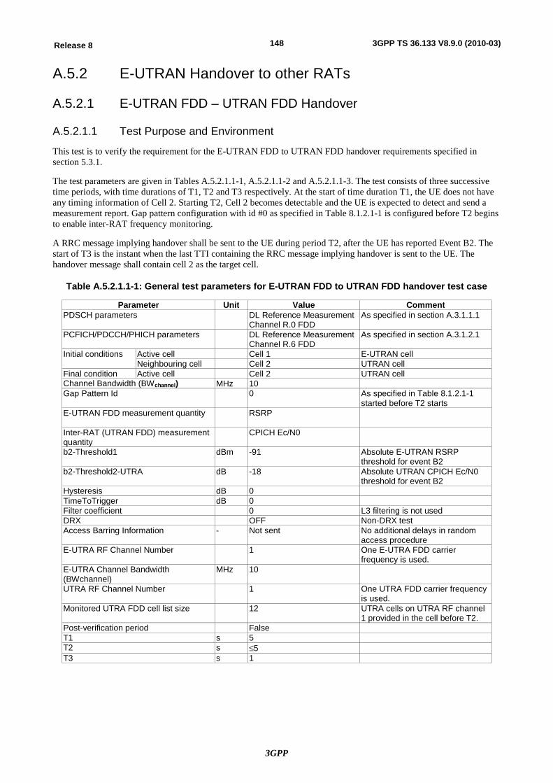
3GPP
148Release 8 3GPP TS 36.133 V8.9.0 (2010-03)
A.5.2 E-UTRAN Handover to other RATs
A.5.2.1 E-UTRAN FDD – UTRAN FDD Handover
A.5.2.1.1 Test Purpose and Environment
This test is to verify the requirement for the E-UTRAN FDD to UTRAN FDD handover requirements specified in section 5.3.1.
The test parameters are given in Tables A.5.2.1.1-1, A.5.2.1.1-2 and A.5.2.1.1-3. The test consists of three successive time periods, with time durations of T1, T2 and T3 respectively. At the start of time duration T1, the UE does not have any timing information of Cell 2. Starting T2, Cell 2 becomes detectable and the UE is expected to detect and send a measurement report. Gap pattern configuration with id #0 as specified in Table 8.1.2.1-1 is configured before T2 begins to enable inter-RAT frequency monitoring.
A RRC message implying handover shall be sent to the UE during period T2, after the UE has reported Event B2. The start of T3 is the instant when the last TTI containing the RRC message implying handover is sent to the UE. The handover message shall contain cell 2 as the target cell.
Table A.5.2.1.1-1: General test parameters for E-UTRAN FDD to UTRAN FDD handover test case
Parameter Unit Value Comment PDSCH parameters DL Reference Measurement
Channel R.0 FDD As specified in section A.3.1.1.1
PCFICH/PDCCH/PHICH parameters DL Reference Measurement Channel R.6 FDD
As specified in section A.3.1.2.1
Initial conditions Active cell Cell 1 E-UTRAN cell Neighbouring cell Cell 2 UTRAN cell
Final condition Active cell Cell 2 UTRAN cell Channel Bandwidth (BWchannel) MHz 10 Gap Pattern Id 0 As specified in Table 8.1.2.1-1
started before T2 starts E-UTRAN FDD measurement quantity
RSRP
Inter-RAT (UTRAN FDD) measurement quantity
CPICH Ec/N0
b2-Threshold1 dBm -91 Absolute E-UTRAN RSRP threshold for event B2
b2-Threshold2-UTRA dB -18 Absolute UTRAN CPICH Ec/N0 threshold for event B2
Hysteresis dB 0 TimeToTrigger dB 0 Filter coefficient 0 L3 filtering is not used DRX OFF Non-DRX test Access Barring Information - Not sent No additional delays in random
access procedure E-UTRA RF Channel Number 1 One E-UTRA FDD carrier
frequency is used. E-UTRA Channel Bandwidth (BWchannel)
MHz 10
UTRA RF Channel Number 1 One UTRA FDD carrier frequency is used.
Monitored UTRA FDD cell list size 12 UTRA cells on UTRA RF channel 1 provided in the cell before T2.
Post-verification period False T1 s 5 T2 s £5 T3 s 1
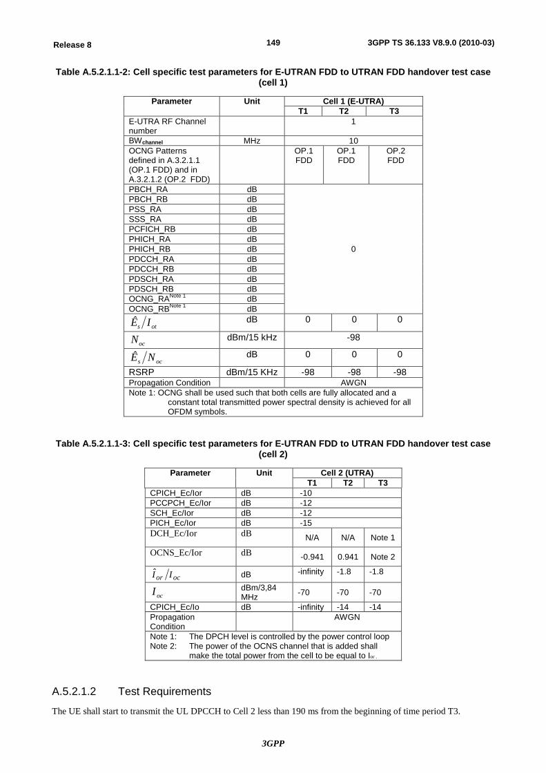
3GPP
149Release 8 3GPP TS 36.133 V8.9.0 (2010-03)
Table A.5.2.1.1-2: Cell specific test parameters for E-UTRAN FDD to UTRAN FDD handover test case (cell 1)
Parameter Unit Cell 1 (E-UTRA) T1 T2 T3
E-UTRA RF Channel number
1
BWchannel MHz 10 OCNG Patterns defined in A.3.2.1.1 (OP.1 FDD) and in A.3.2.1.2 (OP.2 FDD)
OP.1 FDD
OP.1 FDD
OP.2 FDD
PBCH_RA dB
0
PBCH_RB dB PSS_RA dB SSS_RA dB PCFICH_RB dB PHICH_RA dB PHICH_RB dB PDCCH_RA dB PDCCH_RB dB PDSCH_RA dB PDSCH_RB dB OCNG_RANote 1 dB OCNG_RBNote 1 dB
ots IÊ dB 0 0 0
ocN dBm/15 kHz -98
ocs NÊ dB 0 0 0
RSRP dBm/15 KHz -98 -98 -98 Propagation Condition AWGN Note 1: OCNG shall be used such that both cells are fully allocated and a
constant total transmitted power spectral density is achieved for all OFDM symbols.
Table A.5.2.1.1-3: Cell specific test parameters for E-UTRAN FDD to UTRAN FDD handover test case (cell 2)
Parameter Unit Cell 2 (UTRA) T1 T2 T3
CPICH_Ec/Ior dB -10 PCCPCH_Ec/Ior dB -12 SCH_Ec/Ior dB -12 PICH_Ec/Ior dB -15 DCH_Ec/Ior dB N/A N/A Note 1
OCNS_Ec/Ior dB -0.941 0.941 Note 2
ocor II dB -infinity -1.8 -1.8
ocI dBm/3,84 MHz -70 -70 -70
CPICH_Ec/Io dB -infinity -14 -14 Propagation Condition AWGN
Note 1: The DPCH level is controlled by the power control loop Note 2: The power of the OCNS channel that is added shall
make the total power from the cell to be equal to Ior .
A.5.2.1.2 Test Requirements
The UE shall start to transmit the UL DPCCH to Cell 2 less than 190 ms from the beginning of time period T3.
3GPP
150Release 8 3GPP TS 36.133 V8.9.0 (2010-03)
The rate of correct handovers observed during repeated tests shall be at least 90%.
NOTE: The handover delay can be expressed as: RRC procedure delay + Tinterrupt, where:
RRC procedure delay = 50 ms, which is specified in section 5.3.1.1.1.
Tinterrupt = 140 ms in the test; Tinterrupt is defined in section 5.3.1.1.2.
This gives a total of 190 ms.
A.5.2.2 E-UTRAN TDD - UTRAN FDD Handover
A.5.2.2.1 Test Purpose and Environment
This test is to verify the E-UTRAN TDD – UTRAN FDD handover requirements specified in section 5.3.1.
The test scenario comprises of one E-UTRAN TDD cell and one UTRAN FDD cell as given in the tables A.5.2.2.1-1, A5.2.2.1-2 and A.5.2.2.1-3. The test consists of three successive time periods, with time duration of T1, T2 and T3 respectively. At start of time duration T1, the UE does not have any timing information of cell 2. Gap pattern configuration with id #0 as specified in Table 8.1.2.1-1 is configured before the start of T2 to enable the monitoring of UTRAN FDD. A neighbouring cell list, including the UTRAN cell (cell2), shall be sent to the UE before T2 starts. During the time T2 cell 2 becomes detectable and the UE is expected to detect and send the measurement report. A RRC message implying handover shall be sent to the UE during T2, after the UE has reported event B2. The start of T3 is the instant when the last TTI containing the RRC message implying handover is sent to the UE. The handover message shall contain cell 2 as the target cell.
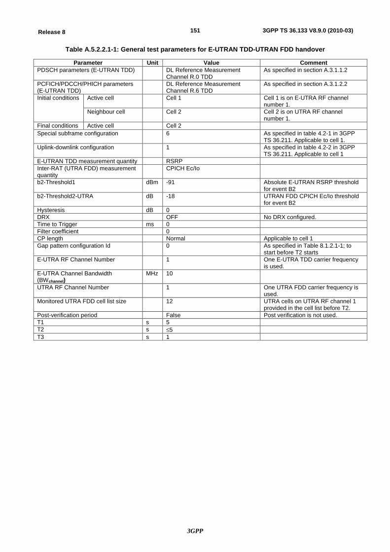
3GPP
151Release 8 3GPP TS 36.133 V8.9.0 (2010-03)
Table A.5.2.2.1-1: General test parameters for E-UTRAN TDD-UTRAN FDD handover
Parameter Unit Value Comment PDSCH parameters (E-UTRAN TDD) DL Reference Measurement
Channel R.0 TDD As specified in section A.3.1.1.2
PCFICH/PDCCH/PHICH parameters (E-UTRAN TDD)
DL Reference Measurement Channel R.6 TDD
As specified in section A.3.1.2.2
Initial conditions Active cell Cell 1 Cell 1 is on E-UTRA RF channel number 1.
Neighbour cell Cell 2 Cell 2 is on UTRA RF channel number 1.
Final conditions Active cell Cell 2 Special subframe configuration 6 As specified in table 4.2-1 in 3GPP
TS 36.211. Applicable to cell 1. Uplink-downlink configuration 1 As specified in table 4.2-2 in 3GPP
TS 36.211. Applicable to cell 1 E-UTRAN TDD measurement quantity RSRP Inter-RAT (UTRA FDD) measurement quantity
CPICH Ec/Io
b2-Threshold1 dBm -91 Absolute E-UTRAN RSRP threshold for event B2
b2-Threshold2-UTRA dB -18 UTRAN FDD CPICH Ec/Io threshold for event B2
Hysteresis dB 0 DRX OFF No DRX configured. Time to Trigger ms 0 Filter coefficient 0 CP length Normal Applicable to cell 1 Gap pattern configuration Id 0 As specified in Table 8.1.2.1-1; to
start before T2 starts E-UTRA RF Channel Number 1 One E-UTRA TDD carrier frequency
is used. E-UTRA Channel Bandwidth (BWchannel)
MHz 10
UTRA RF Channel Number 1 One UTRA FDD carrier frequency is used.
Monitored UTRA FDD cell list size 12 UTRA cells on UTRA RF channel 1 provided in the cell list before T2.
Post-verification period False Post verification is not used. T1 s 5 T2 s £5 T3 s 1
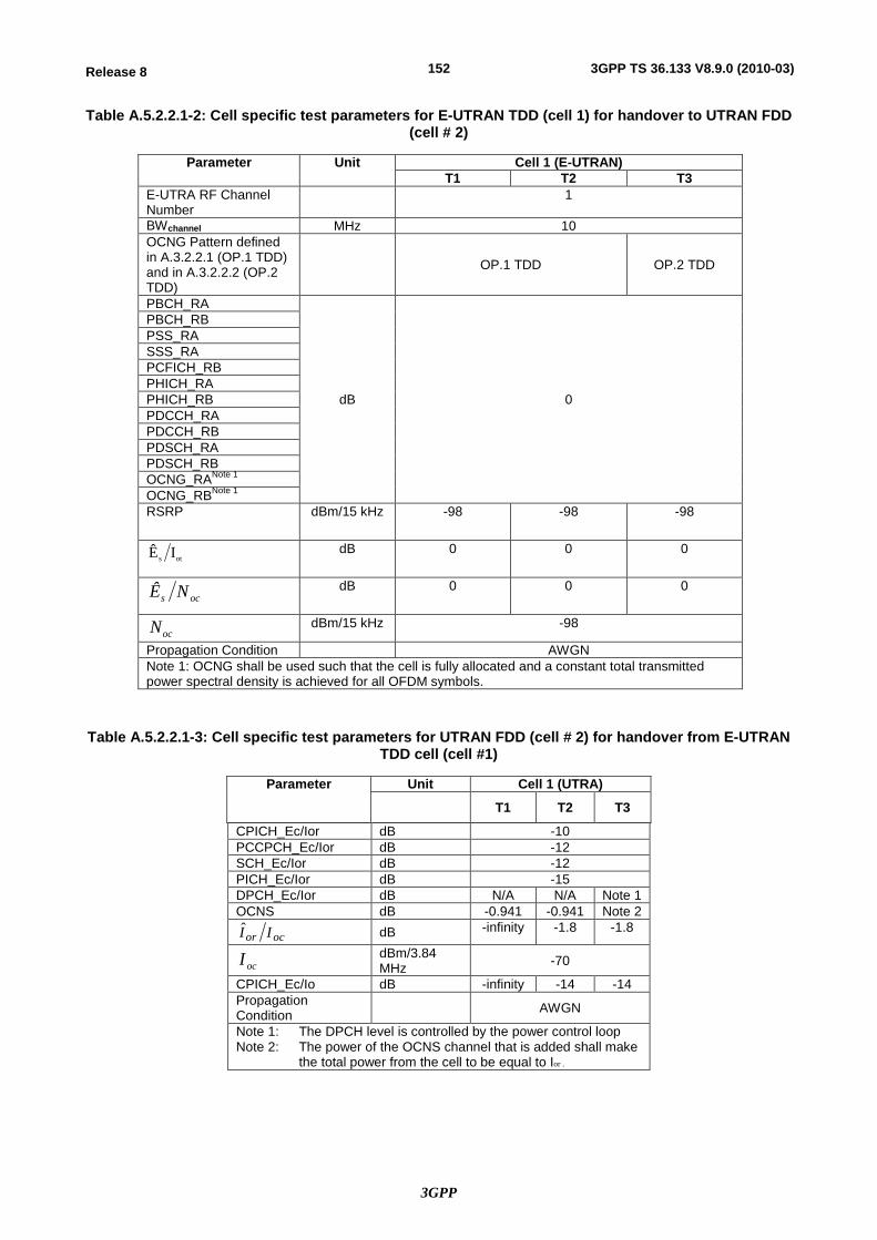
3GPP
152Release 8 3GPP TS 36.133 V8.9.0 (2010-03)
Table A.5.2.2.1-2: Cell specific test parameters for E-UTRAN TDD (cell 1) for handover to UTRAN FDD (cell # 2)
Parameter Unit Cell 1 (E-UTRAN) T1 T2 T3
E-UTRA RF Channel Number
1
BWchannel MHz 10 OCNG Pattern defined in A.3.2.2.1 (OP.1 TDD) and in A.3.2.2.2 (OP.2 TDD)
OP.1 TDD OP.2 TDD
PBCH_RA
dB 0
PBCH_RB PSS_RA SSS_RA PCFICH_RB PHICH_RA PHICH_RB PDCCH_RA PDCCH_RB PDSCH_RA PDSCH_RB OCNG_RANote 1 OCNG_RBNote 1 RSRP dBm/15 kHz -98 -98 -98
ots IÊ dB 0 0 0
ocs NÊ dB 0 0 0
ocN dBm/15 kHz -98
Propagation Condition AWGN Note 1: OCNG shall be used such that the cell is fully allocated and a constant total transmitted power spectral density is achieved for all OFDM symbols.
Table A.5.2.2.1-3: Cell specific test parameters for UTRAN FDD (cell # 2) for handover from E-UTRAN TDD cell (cell #1)
Parameter Unit Cell 1 (UTRA) T1 T2 T3
CPICH_Ec/Ior dB -10 PCCPCH_Ec/Ior dB -12 SCH_Ec/Ior dB -12 PICH_Ec/Ior dB -15 DPCH_Ec/Ior dB N/A N/A Note 1 OCNS dB -0.941 -0.941 Note 2
ocor II dB -infinity -1.8 -1.8
ocI dBm/3.84 MHz -70
CPICH_Ec/Io dB -infinity -14 -14 Propagation Condition AWGN
Note 1: The DPCH level is controlled by the power control loop Note 2: The power of the OCNS channel that is added shall make
the total power from the cell to be equal to Ior .
3GPP
153Release 8 3GPP TS 36.133 V8.9.0 (2010-03)
A.5.2.2.2 Test Requirements
The UE shall start to transmit the UL DPCCH to Cell 2 less than 190 ms from the beginning of time period T3.
The rate of correct handovers observed during repeated tests shall be at least 90%.
NOTE: The handover delay can be expressed as: RRC procedure delay + Tinterrupt, where:
RRC procedure delay = 50 ms, which is specified in section 5.1.1.1.1.
Tinterrupt = 140 ms in the test; Tinterrupt is defined in section 5.3.1.1.2.
This gives a total of 190 ms.
A.5.2.3 E-UTRAN FDD- GSM Handover
A.5.2.3.1 Test Purpose and Environment
This test is to verify the requirement for the E-UTRAN to GSM cell handover delay specified in section 5.3.3.
The test parameters are given in Table A.5.2.3.1 -1, A.5.2.3.1 -2 and A.5.2.3.1 -3 below. In the measurement control information it is indicated to the UE that event-triggered reporting with Event B1 shall be used. The test consists of three successive time periods, with time duration of T1, T2 and T3 respectively. At the start of time duration T1, the UE may not have any timing information of cell 2.
The RRC message implying handover to cell 2 shall be sent to the UE during period T2, after the UE has reported Event B1. The start of T3 is defined as the end of last E-UTRAN TTI containing the RRC message implying handover.
The requirements are also applicable for a UE not requiring measurement gap, in which case no measurement gap pattern should be sent for the parameters specified in Table A.5.2.3.1 -1.
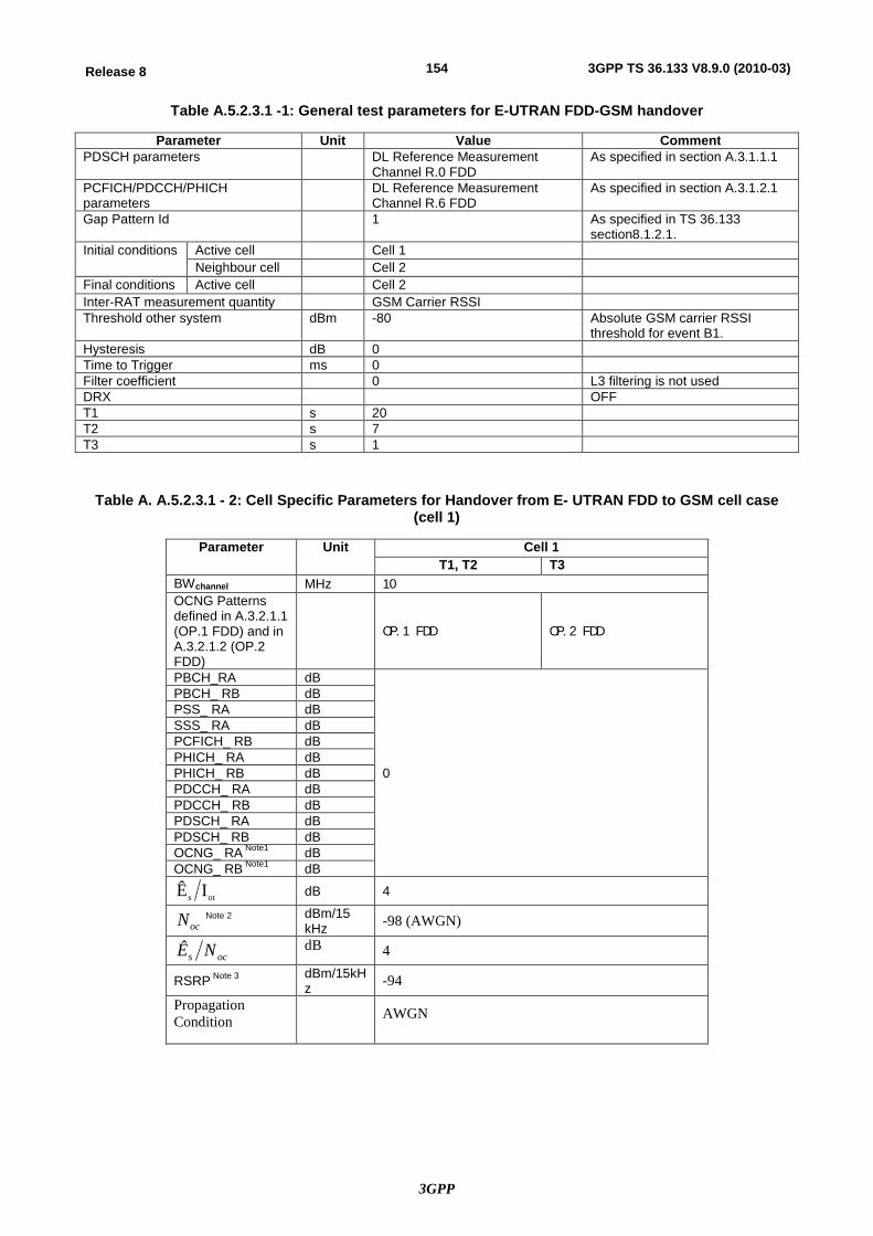
3GPP
154Release 8 3GPP TS 36.133 V8.9.0 (2010-03)
Table A.5.2.3.1 -1: General test parameters for E-UTRAN FDD-GSM handover
Parameter Unit Value Comment PDSCH parameters DL Reference Measurement
Channel R.0 FDD As specified in section A.3.1.1.1
PCFICH/PDCCH/PHICH parameters
DL Reference Measurement Channel R.6 FDD
As specified in section A.3.1.2.1
Gap Pattern Id 1 As specified in TS 36.133 section8.1.2.1.
Initial conditions Active cell Cell 1 Neighbour cell Cell 2
Final conditions Active cell Cell 2 Inter-RAT measurement quantity GSM Carrier RSSI Threshold other system dBm -80 Absolute GSM carrier RSSI
threshold for event B1. Hysteresis dB 0 Time to Trigger ms 0 Filter coefficient 0 L3 filtering is not used DRX OFF T1 s 20 T2 s 7 T3 s 1
Table A. A.5.2.3.1 - 2: Cell Specific Parameters for Handover from E- UTRAN FDD to GSM cell case (cell 1)
Parameter Unit Cell 1 T1, T2 T3
BWchannel MHz 10 OCNG Patterns defined in A.3.2.1.1 (OP.1 FDD) and in A.3.2.1.2 (OP.2 FDD)
OP.1 FDD OP.2 FDD
PBCH_RA dB
0
PBCH_ RB dB PSS_ RA dB SSS_ RA dB PCFICH_ RB dB PHICH_ RA dB PHICH_ RB dB PDCCH_ RA dB PDCCH_ RB dB PDSCH_ RA dB PDSCH_ RB dB OCNG_ RA Note1 dB OCNG_ RB Note1 dB
ots IÊ dB 4
ocN Note 2 dBm/15 kHz -98 (AWGN)
ocs NÊ dB 4
RSRP Note 3 dBm/15kHz -94
Propagation Condition AWGN
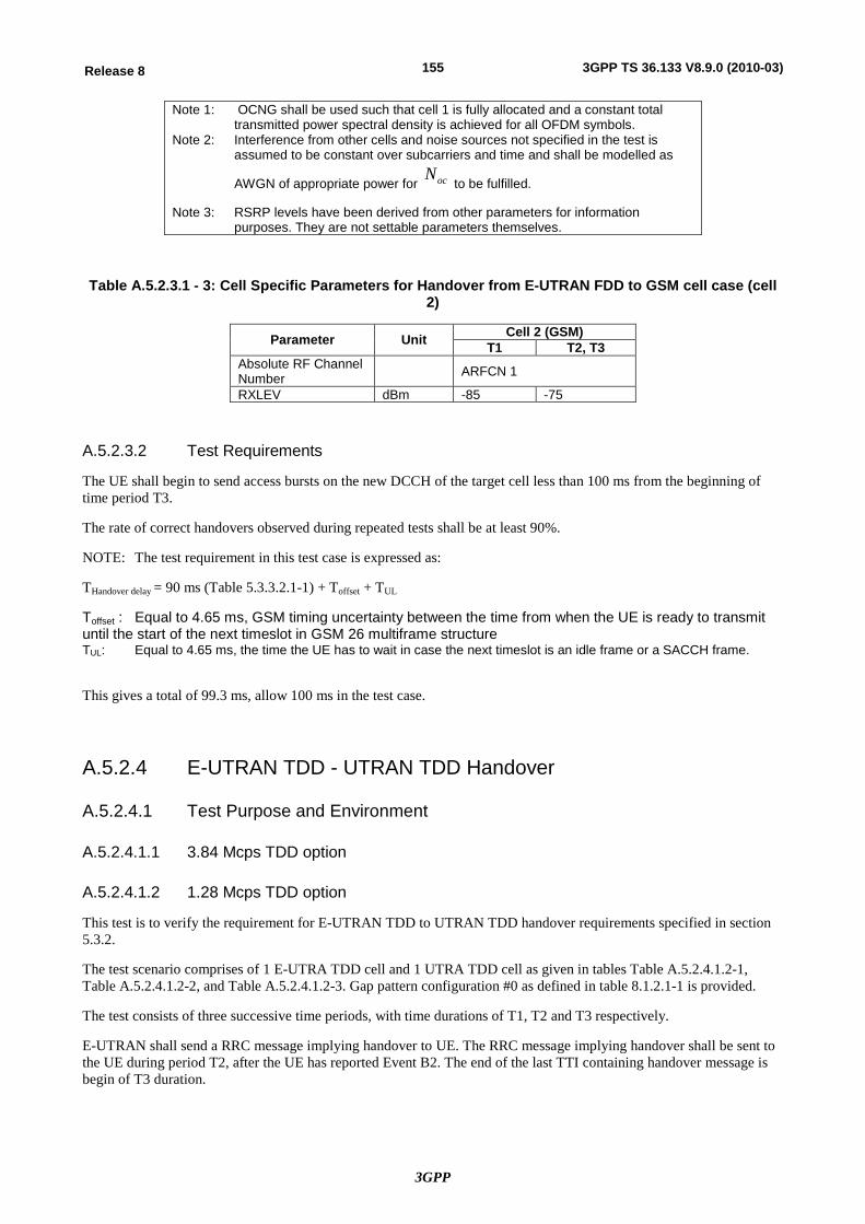
3GPP
155Release 8 3GPP TS 36.133 V8.9.0 (2010-03)
Note 1: OCNG shall be used such that cell 1 is fully allocated and a constant total transmitted power spectral density is achieved for all OFDM symbols.
Note 2: Interference from other cells and noise sources not specified in the test is assumed to be constant over subcarriers and time and shall be modelled as
AWGN of appropriate power for ocN to be fulfilled.
Note 3: RSRP levels have been derived from other parameters for information
purposes. They are not settable parameters themselves.
Table A.5.2.3.1 - 3: Cell Specific Parameters for Handover from E-UTRAN FDD to GSM cell case (cell 2)
Parameter Unit Cell 2 (GSM) T1 T2, T3
Absolute RF Channel Number ARFCN 1
RXLEV dBm -85 -75
A.5.2.3.2 Test Requirements
The UE shall begin to send access bursts on the new DCCH of the target cell less than 100 ms from the beginning of time period T3.
The rate of correct handovers observed during repeated tests shall be at least 90%.
NOTE: The test requirement in this test case is expressed as:
THandover delay = 90 ms (Table 5.3.3.2.1-1) + Toffset + TUL
Toffset : Equal to 4.65 ms, GSM timing uncertainty between the time from when the UE is ready to transmit until the start of the next timeslot in GSM 26 multiframe structure TUL: Equal to 4.65 ms, the time the UE has to wait in case the next timeslot is an idle frame or a SACCH frame.
This gives a total of 99.3 ms, allow 100 ms in the test case.
A.5.2.4 E-UTRAN TDD - UTRAN TDD Handover
A.5.2.4.1 Test Purpose and Environment
A.5.2.4.1.1 3.84 Mcps TDD option
A.5.2.4.1.2 1.28 Mcps TDD option
This test is to verify the requirement for E-UTRAN TDD to UTRAN TDD handover requirements specified in section 5.3.2.
The test scenario comprises of 1 E-UTRA TDD cell and 1 UTRA TDD cell as given in tables Table A.5.2.4.1.2-1, Table A.5.2.4.1.2-2, and Table A.5.2.4.1.2-3. Gap pattern configuration #0 as defined in table 8.1.2.1-1 is provided.
The test consists of three successive time periods, with time durations of T1, T2 and T3 respectively.
E-UTRAN shall send a RRC message implying handover to UE. The RRC message implying handover shall be sent to the UE during period T2, after the UE has reported Event B2. The end of the last TTI containing handover message is begin of T3 duration.
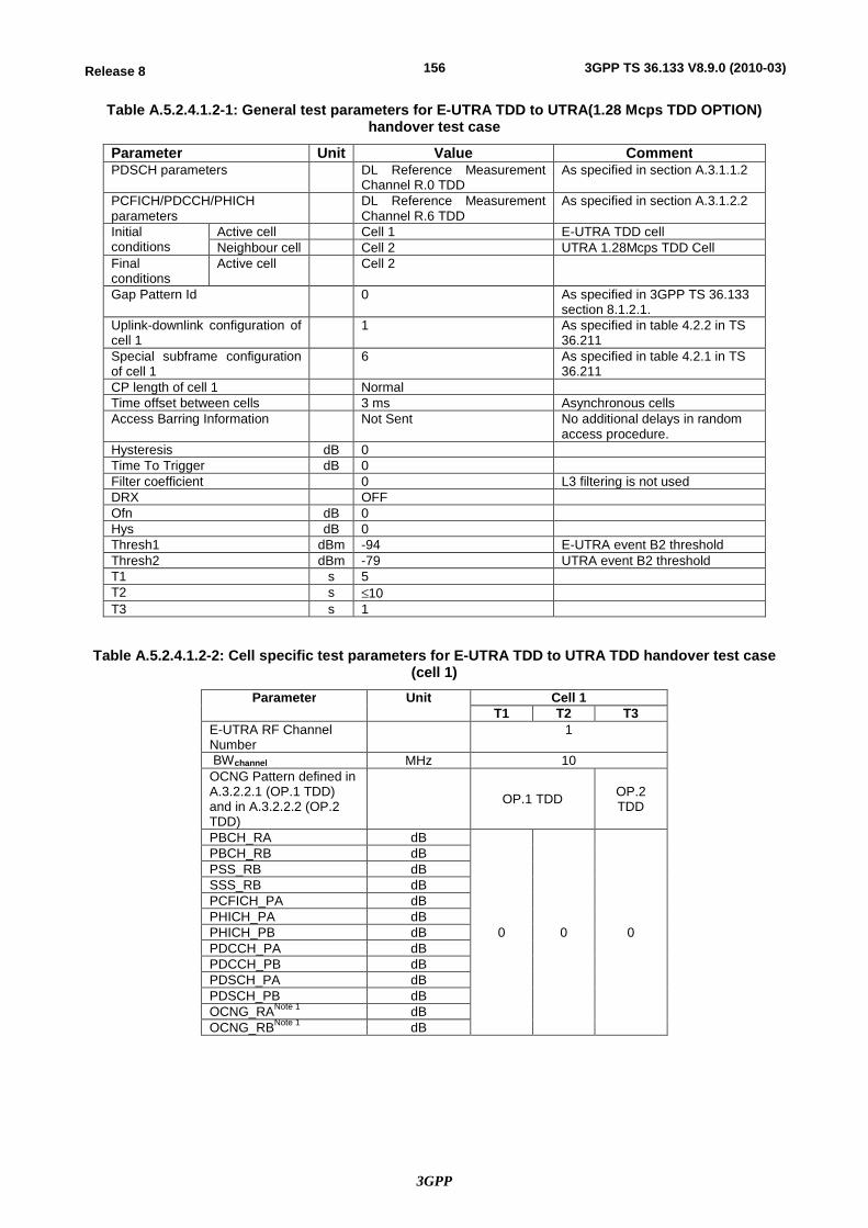
3GPP
156Release 8 3GPP TS 36.133 V8.9.0 (2010-03)
Table A.5.2.4.1.2-1: General test parameters for E-UTRA TDD to UTRA(1.28 Mcps TDD OPTION) handover test case
Parameter Unit Value Comment PDSCH parameters DL Reference Measurement
Channel R.0 TDD As specified in section A.3.1.1.2
PCFICH/PDCCH/PHICH parameters
DL Reference Measurement Channel R.6 TDD
As specified in section A.3.1.2.2
Initial conditions
Active cell Cell 1 E-UTRA TDD cell Neighbour cell Cell 2 UTRA 1.28Mcps TDD Cell
Final conditions
Active cell Cell 2
Gap Pattern Id 0 As specified in 3GPP TS 36.133 section 8.1.2.1.
Uplink-downlink configuration of cell 1
1 As specified in table 4.2.2 in TS 36.211
Special subframe configuration of cell 1
6 As specified in table 4.2.1 in TS 36.211
CP length of cell 1 Normal Time offset between cells 3 ms Asynchronous cells Access Barring Information Not Sent No additional delays in random
access procedure. Hysteresis dB 0 Time To Trigger dB 0 Filter coefficient 0 L3 filtering is not used DRX OFF Ofn dB 0 Hys dB 0 Thresh1 dBm -94 E-UTRA event B2 threshold Thresh2 dBm -79 UTRA event B2 threshold T1 s 5 T2 s £10 T3 s 1
Table A.5.2.4.1.2-2: Cell specific test parameters for E-UTRA TDD to UTRA TDD handover test case (cell 1)
Parameter Unit Cell 1 T1 T2 T3
E-UTRA RF Channel Number
1
BWchannel MHz 10 OCNG Pattern defined in A.3.2.2.1 (OP.1 TDD) and in A.3.2.2.2 (OP.2 TDD)
OP.1 TDD OP.2 TDD
PBCH_RA dB
0 0 0
PBCH_RB dB PSS_RB dB SSS_RB dB PCFICH_PA dB PHICH_PA dB PHICH_PB dB PDCCH_PA dB PDCCH_PB dB PDSCH_PA dB PDSCH_PB dB OCNG_RANote 1 dB OCNG_RBNote 1 dB
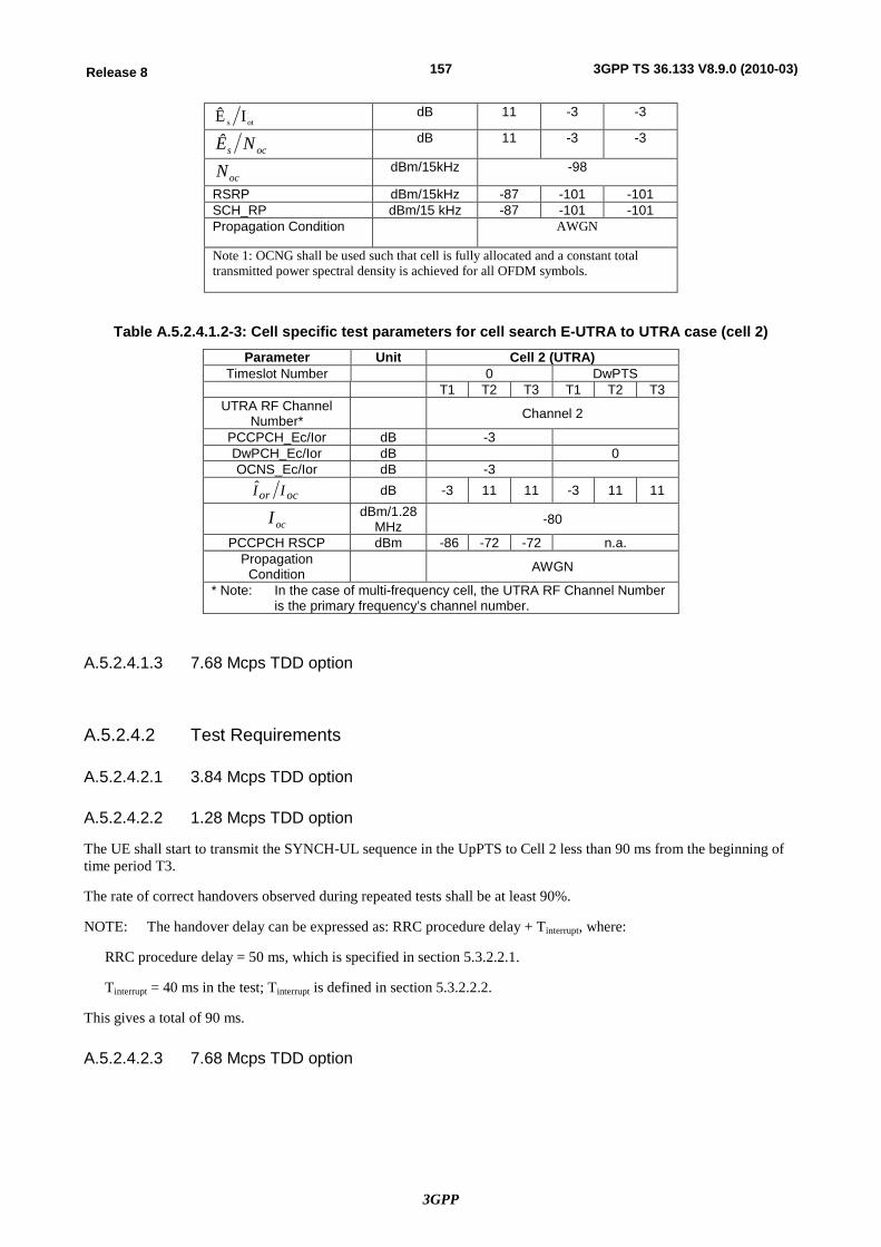
3GPP
157Release 8 3GPP TS 36.133 V8.9.0 (2010-03)
ots IÊ dB 11 -3 -3
ocs NÊ dB 11 -3 -3
ocN dBm/15kHz -98
RSRP dBm/15kHz -87 -101 -101 SCH_RP dBm/15 kHz -87 -101 -101 Propagation Condition AWGN
Note 1: OCNG shall be used such that cell is fully allocated and a constant total transmitted power spectral density is achieved for all OFDM symbols.
Table A.5.2.4.1.2-3: Cell specific test parameters for cell search E-UTRA to UTRA case (cell 2) Parameter Unit Cell 2 (UTRA)
Timeslot Number 0 DwPTS T1 T2 T3 T1 T2 T3
UTRA RF Channel Number* Channel 2
PCCPCH_Ec/Ior dB -3 DwPCH_Ec/Ior dB 0 OCNS_Ec/Ior dB -3
ocor II dB -3 11 11 -3 11 11
ocI dBm/1.28 MHz -80
PCCPCH RSCP dBm -86 -72 -72 n.a. Propagation
Condition AWGN
* Note: In the case of multi-frequency cell, the UTRA RF Channel Number is the primary frequency’s channel number.
A.5.2.4.1.3 7.68 Mcps TDD option
A.5.2.4.2 Test Requirements
A.5.2.4.2.1 3.84 Mcps TDD option
A.5.2.4.2.2 1.28 Mcps TDD option
The UE shall start to transmit the SYNCH-UL sequence in the UpPTS to Cell 2 less than 90 ms from the beginning of time period T3.
The rate of correct handovers observed during repeated tests shall be at least 90%.
NOTE: The handover delay can be expressed as: RRC procedure delay + Tinterrupt, where:
RRC procedure delay = 50 ms, which is specified in section 5.3.2.2.1.
Tinterrupt = 40 ms in the test; Tinterrupt is defined in section 5.3.2.2.2.
This gives a total of 90 ms.
A.5.2.4.2.3 7.68 Mcps TDD option
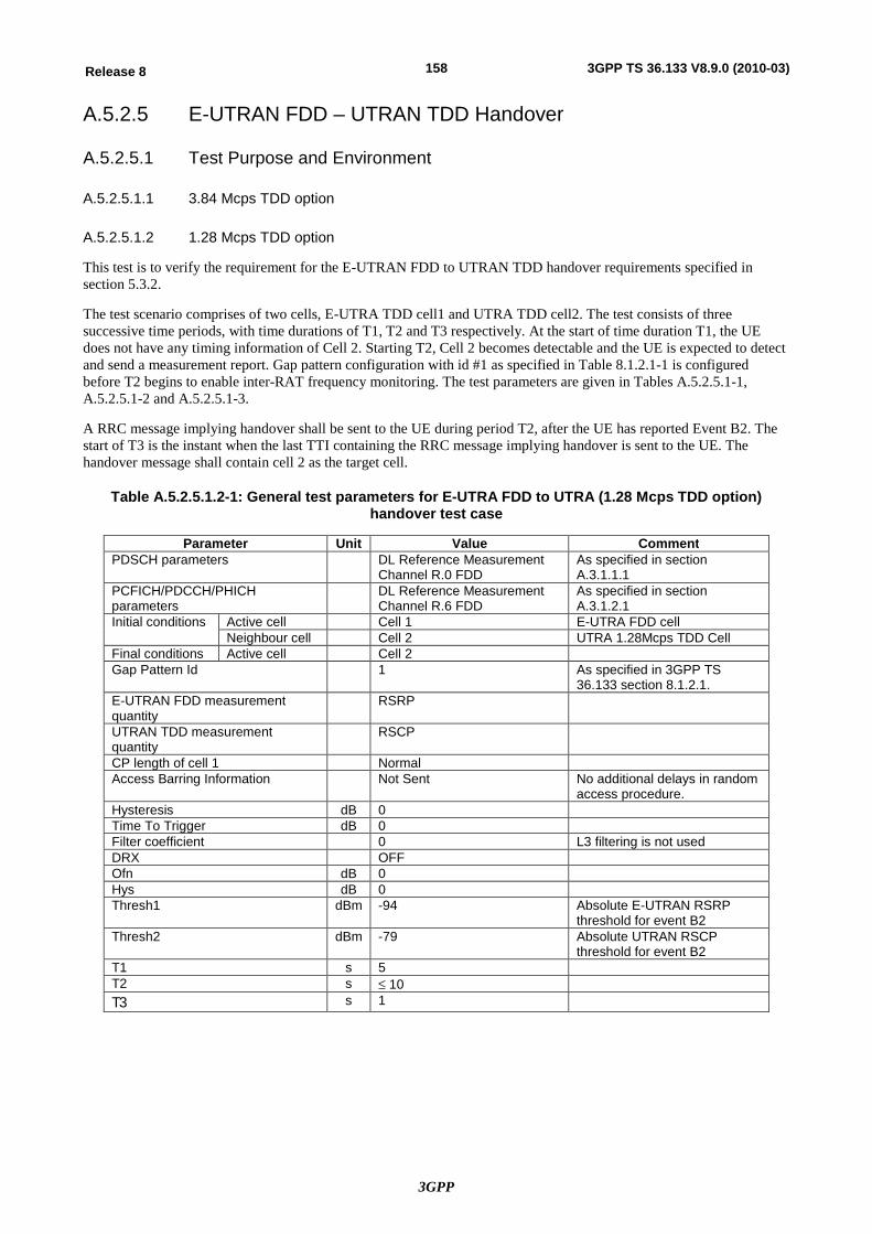
3GPP
158Release 8 3GPP TS 36.133 V8.9.0 (2010-03)
A.5.2.5 E-UTRAN FDD – UTRAN TDD Handover
A.5.2.5.1 Test Purpose and Environment
A.5.2.5.1.1 3.84 Mcps TDD option
A.5.2.5.1.2 1.28 Mcps TDD option
This test is to verify the requirement for the E-UTRAN FDD to UTRAN TDD handover requirements specified in section 5.3.2.
The test scenario comprises of two cells, E-UTRA TDD cell1 and UTRA TDD cell2. The test consists of three successive time periods, with time durations of T1, T2 and T3 respectively. At the start of time duration T1, the UE does not have any timing information of Cell 2. Starting T2, Cell 2 becomes detectable and the UE is expected to detect and send a measurement report. Gap pattern configuration with id #1 as specified in Table 8.1.2.1-1 is configured before T2 begins to enable inter-RAT frequency monitoring. The test parameters are given in Tables A.5.2.5.1-1, A.5.2.5.1-2 and A.5.2.5.1-3.
A RRC message implying handover shall be sent to the UE during period T2, after the UE has reported Event B2. The start of T3 is the instant when the last TTI containing the RRC message implying handover is sent to the UE. The handover message shall contain cell 2 as the target cell.
Table A.5.2.5.1.2-1: General test parameters for E-UTRA FDD to UTRA (1.28 Mcps TDD option) handover test case
Parameter Unit Value Comment PDSCH parameters DL Reference Measurement
Channel R.0 FDD As specified in section A.3.1.1.1
PCFICH/PDCCH/PHICH parameters
DL Reference Measurement Channel R.6 FDD
As specified in section A.3.1.2.1
Initial conditions Active cell Cell 1 E-UTRA FDD cell Neighbour cell Cell 2 UTRA 1.28Mcps TDD Cell
Final conditions Active cell Cell 2 Gap Pattern Id 1 As specified in 3GPP TS
36.133 section 8.1.2.1. E-UTRAN FDD measurement quantity
RSRP
UTRAN TDD measurement quantity
RSCP
CP length of cell 1 Normal Access Barring Information Not Sent No additional delays in random
access procedure. Hysteresis dB 0 Time To Trigger dB 0 Filter coefficient 0 L3 filtering is not used DRX OFF Ofn dB 0 Hys dB 0 Thresh1 dBm -94 Absolute E-UTRAN RSRP
threshold for event B2 Thresh2 dBm -79 Absolute UTRAN RSCP
threshold for event B2 T1 s 5 T2 s £ 10 T3 s 1
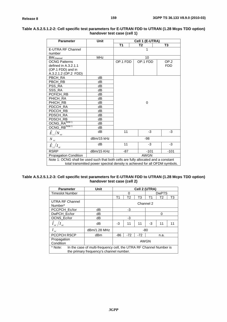
3GPP
159Release 8 3GPP TS 36.133 V8.9.0 (2010-03)
Table A.5.2.5.1.2-2: Cell specific test parameters for E-UTRAN FDD to UTRAN (1.28 Mcps TDD option) handover test case (cell 1)
Parameter Unit Cell 1 (E-UTRA) T1 T2 T3
E-UTRA RF Channel number
1
BWchannel MHz 10 OCNG Patterns defined in A.3.2.1.1 (OP.1 FDD) and in A.3.2.1.2 (OP.2 FDD)
OP.1 FDD OP.1 FDD OP.2 FDD
PBCH_RA dB
0
PBCH_RB dB PSS_RA dB SSS_RA dB PCFICH_RB dB PHICH_RA dB PHICH_RB dB PDCCH_RA dB PDCCH_RB dB PDSCH_RA dB PDSCH_RB dB OCNG_RANote 1 dB OCNG_RBNote 1 dB
ocs NE dB 11 -3 -3
ocN dBm/15 kHz -98
ots IE dB 11 -3 -3
RSRP dBm/15 KHz -87 -101 -101 Propagation Condition AWGN Note 1: OCNG shall be used such that both cells are fully allocated and a constant
total transmitted power spectral density is achieved for all OFDM symbols.
Table A.5.2.5.1.2-3: Cell specific test parameters for E-UTRAN FDD to UTRAN (1.28 Mcps TDD option) handover test case (cell 2)
Parameter Unit Cell 2 (UTRA) Timeslot Number 0 DwPTS T1 T2 T3 T1 T2 T3 UTRA RF Channel Number* Channel 2
PCCPCH_Ec/Ior dB -3 DwPCH_Ec/Ior dB 0 OCNS_Ec/Ior dB -3
ocor II dB -3 11 11 -3 11 11
ocI dBm/1.28 MHz -80 PCCPCH RSCP dBm -86 -72 -72 n.a. Propagation Condition AWGN
* Note: In the case of multi-frequency cell, the UTRA RF Channel Number is the primary frequency’s channel number.
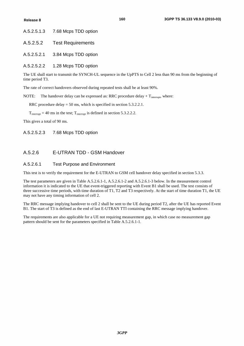
3GPP
160Release 8 3GPP TS 36.133 V8.9.0 (2010-03)
A.5.2.5.1.3 7.68 Mcps TDD option
A.5.2.5.2 Test Requirements
A.5.2.5.2.1 3.84 Mcps TDD option
A.5.2.5.2.2 1.28 Mcps TDD option
The UE shall start to transmit the SYNCH-UL sequence in the UpPTS to Cell 2 less than 90 ms from the beginning of time period T3.
The rate of correct handovers observed during repeated tests shall be at least 90%.
NOTE: The handover delay can be expressed as: RRC procedure delay + Tinterrupt, where:
RRC procedure delay = 50 ms, which is specified in section 5.3.2.2.1.
Tinterrupt = 40 ms in the test; Tinterrupt is defined in section 5.3.2.2.2.
This gives a total of 90 ms.
A.5.2.5.2.3 7.68 Mcps TDD option
A.5.2.6 E-UTRAN TDD - GSM Handover
A.5.2.6.1 Test Purpose and Environment
This test is to verify the requirement for the E-UTRAN to GSM cell handover delay specified in section 5.3.3.
The test parameters are given in Table A.5.2.6.1-1, A.5.2.6.1-2 and A.5.2.6.1-3 below. In the measurement control information it is indicated to the UE that event-triggered reporting with Event B1 shall be used. The test consists of three successive time periods, with time duration of T1, T2 and T3 respectively. At the start of time duration T1, the UE may not have any timing information of cell 2.
The RRC message implying handover to cell 2 shall be sent to the UE during period T2, after the UE has reported Event B1. The start of T3 is defined as the end of last E-UTRAN TTI containing the RRC message implying handover.
The requirements are also applicable for a UE not requiring measurement gap, in which case no measurement gap pattern should be sent for the parameters specified in Table A.5.2.6.1-1.
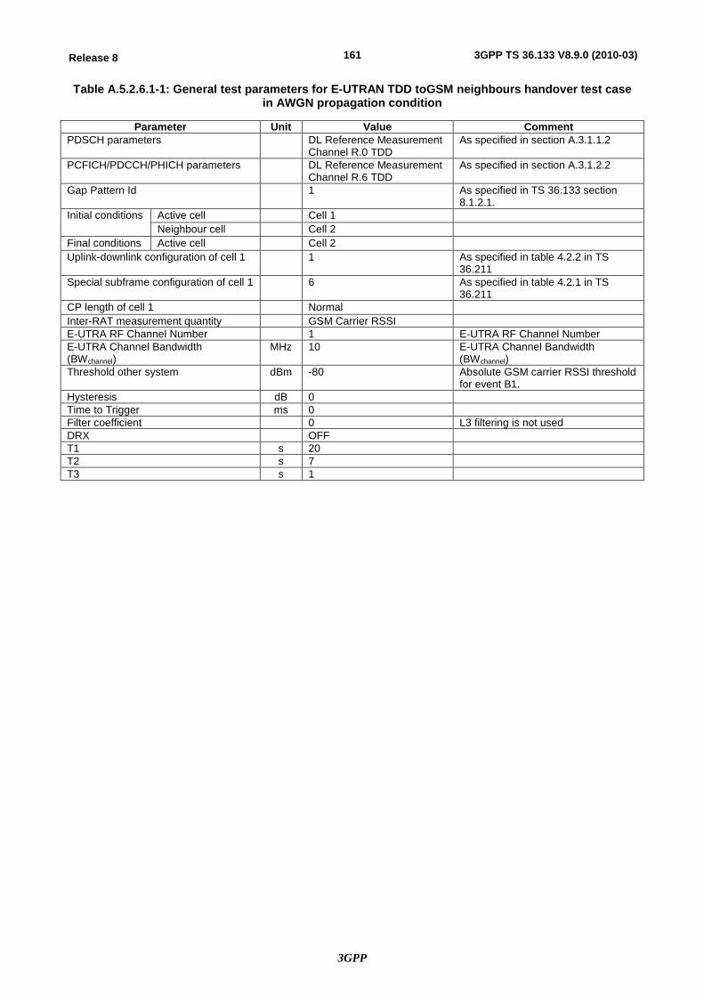
3GPP
161Release 8 3GPP TS 36.133 V8.9.0 (2010-03)
Table A.5.2.6.1-1: General test parameters for E-UTRAN TDD toGSM neighbours handover test case in AWGN propagation condition
Parameter Unit Value Comment PDSCH parameters DL Reference Measurement
Channel R.0 TDD As specified in section A.3.1.1.2
PCFICH/PDCCH/PHICH parameters DL Reference Measurement Channel R.6 TDD
As specified in section A.3.1.2.2
Gap Pattern Id 1 As specified in TS 36.133 section 8.1.2.1.
Initial conditions Active cell Cell 1 Neighbour cell Cell 2
Final conditions Active cell Cell 2 Uplink-downlink configuration of cell 1 1 As specified in table 4.2.2 in TS
36.211 Special subframe configuration of cell 1 6 As specified in table 4.2.1 in TS
36.211 CP length of cell 1 Normal Inter-RAT measurement quantity GSM Carrier RSSI E-UTRA RF Channel Number 1 E-UTRA RF Channel Number E-UTRA Channel Bandwidth (BWchannel)
MHz 10 E-UTRA Channel Bandwidth (BWchannel)
Threshold other system dBm -80 Absolute GSM carrier RSSI threshold for event B1.
Hysteresis dB 0 Time to Trigger ms 0 Filter coefficient 0 L3 filtering is not used DRX OFF T1 s 20 T2 s 7 T3 s 1
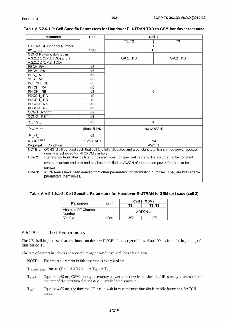
3GPP
162Release 8 3GPP TS 36.133 V8.9.0 (2010-03)
Table A.5.2.6.1-2: Cell Specific Parameters for Handover E- UTRAN TDD to GSM handover test case
Parameter Unit Cell 1 T1, T2 T3
E-UTRA RF Channel Number 1 BWchannel MHz 10 OCNG Patterns defined in A.3.2.2.1 (OP.1 TDD) and in A.3.2.2.2 (OP.2 TDD)
OP.1 TDD OP.2 TDD
PBCH_RA dB
0
PBCH_ RB dB PSS_ RA dB SSS_ RA dB PCFICH_ RB dB PHICH_ RA dB PHICH_ RB dB PDCCH_ RA dB PDCCH_ RB dB PDSCH_ RA dB PDSCH_ RB dB OCNG_ RA Note1 dB OCNG_ RB Note1 dB
ocs NE dB 4
ocN Note 2 dBm/15 kHz -98 (AWGN)
ots IE dB 4 RSRP Note 3 dBm/15kHz -94 Propagation Condition AWGN NOTE 1: OCNG shall be used such that cell 1 is fully allocated and a constant total transmitted power spectral
density is achieved for all OFDM symbols. Note 2: Interference from other cells and noise sources not specified in the test is assumed to be constant
over subcarriers and time and shall be modelled as AWGN of appropriate power for ocN to be fulfilled.
Note 3: RSRP levels have been derived from other parameters for information purposes. They are not settable parameters themselves.
Table A A.5.2.6.1-3: Cell Specific Parameters for Handover E-UTRAN to GSM cell case (cell 2)
Parameter Unit Cell 2 (GSM) T1 T2, T3
Absolute RF Channel Number ARFCN 1
RXLEV dBm -85 -75
A.5.2.6.2 Test Requirements
The UE shall begin to send access bursts on the new DCCH of the target cell less than 100 ms from the beginning of time period T3.
The rate of correct handovers observed during repeated tests shall be at least 90%.
NOTE: The test requirement in this test case is expressed as:
THandover delay = 90 ms (Table 5.3.3.2.1-1) + Toffset + TUL
Toffset: Equal to 4.65 ms, GSM timing uncertainty between the time from when the UE is ready to transmit until the start of the next timeslot in GSM 26 multiframe structure
TUL: Equal to 4.65 ms, the time the UE has to wait in case the next timeslot is an idle frame or a SACCH frame.
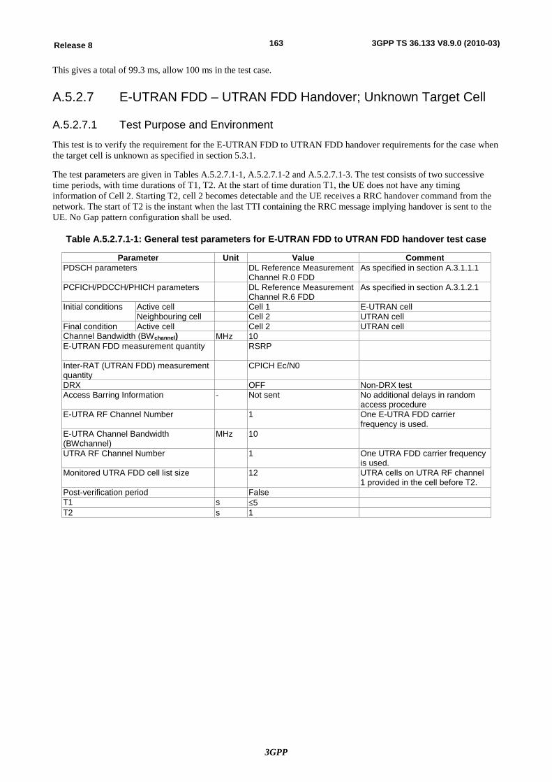
3GPP
163Release 8 3GPP TS 36.133 V8.9.0 (2010-03)
This gives a total of 99.3 ms, allow 100 ms in the test case.
A.5.2.7 E-UTRAN FDD – UTRAN FDD Handover; Unknown Target Cell
A.5.2.7.1 Test Purpose and Environment
This test is to verify the requirement for the E-UTRAN FDD to UTRAN FDD handover requirements for the case when the target cell is unknown as specified in section 5.3.1.
The test parameters are given in Tables A.5.2.7.1-1, A.5.2.7.1-2 and A.5.2.7.1-3. The test consists of two successive time periods, with time durations of T1, T2. At the start of time duration T1, the UE does not have any timing information of Cell 2. Starting T2, cell 2 becomes detectable and the UE receives a RRC handover command from the network. The start of T2 is the instant when the last TTI containing the RRC message implying handover is sent to the UE. No Gap pattern configuration shall be used.
Table A.5.2.7.1-1: General test parameters for E-UTRAN FDD to UTRAN FDD handover test case
Parameter Unit Value Comment PDSCH parameters DL Reference Measurement
Channel R.0 FDD As specified in section A.3.1.1.1
PCFICH/PDCCH/PHICH parameters DL Reference Measurement Channel R.6 FDD
As specified in section A.3.1.2.1
Initial conditions Active cell Cell 1 E-UTRAN cell Neighbouring cell Cell 2 UTRAN cell
Final condition Active cell Cell 2 UTRAN cell Channel Bandwidth (BWchannel) MHz 10 E-UTRAN FDD measurement quantity
RSRP
Inter-RAT (UTRAN FDD) measurement quantity
CPICH Ec/N0
DRX OFF Non-DRX test Access Barring Information - Not sent No additional delays in random
access procedure E-UTRA RF Channel Number 1 One E-UTRA FDD carrier
frequency is used. E-UTRA Channel Bandwidth (BWchannel)
MHz 10
UTRA RF Channel Number 1 One UTRA FDD carrier frequency is used.
Monitored UTRA FDD cell list size 12 UTRA cells on UTRA RF channel 1 provided in the cell before T2.
Post-verification period False T1 s £5 T2 s 1

3GPP
164Release 8 3GPP TS 36.133 V8.9.0 (2010-03)
Table A.5.2.7.1-2: Cell specific test parameters for E-UTRAN FDD to UTRAN FDD handover test case (cell 1)
Parameter Unit Cell 1 (E-UTRA) T1 T2
E-UTRA RF Channel number
1
BWchannel MHz 10 OCNG Patterns defined in A.3.2.1.1 (OP.1 FDD) and in A.3.2.1.2 (OP.2 FDD)
OP.1 FDD OP.2 FDD
PBCH_RA dB
0
PBCH_RB dB PSS_RA dB SSS_RA dB PCFICH_RB dB PHICH_RA dB PHICH_RB dB PDCCH_RA dB PDCCH_RB dB PDSCH_RA dB PDSCH_RB dB OCNG_RANote 1 dB OCNG_RBNote 1 dB
ots IÊ dB 0 0
ocN Note 2 dBm/15 kHz -98
ocs NÊ dB 0 0
RSRP Note 3 dBm/15 KHz -98 -98 Propagation Condition AWGN Note 1: OCNG shall be used such that both cells are fully allocated and
a constant total transmitted power spectral density is achieved for all OFDM symbols.
Note 2: Interference from other cells and noise sources not specified in the test is assumed to be constant over subcarriers and time
and shall be modelled as AWGN of appropriate power for ocN
to be fulfilled. Note 3: RSRP levels have been derived from other parameters for
information purposes. They are not settable parameters themselves.
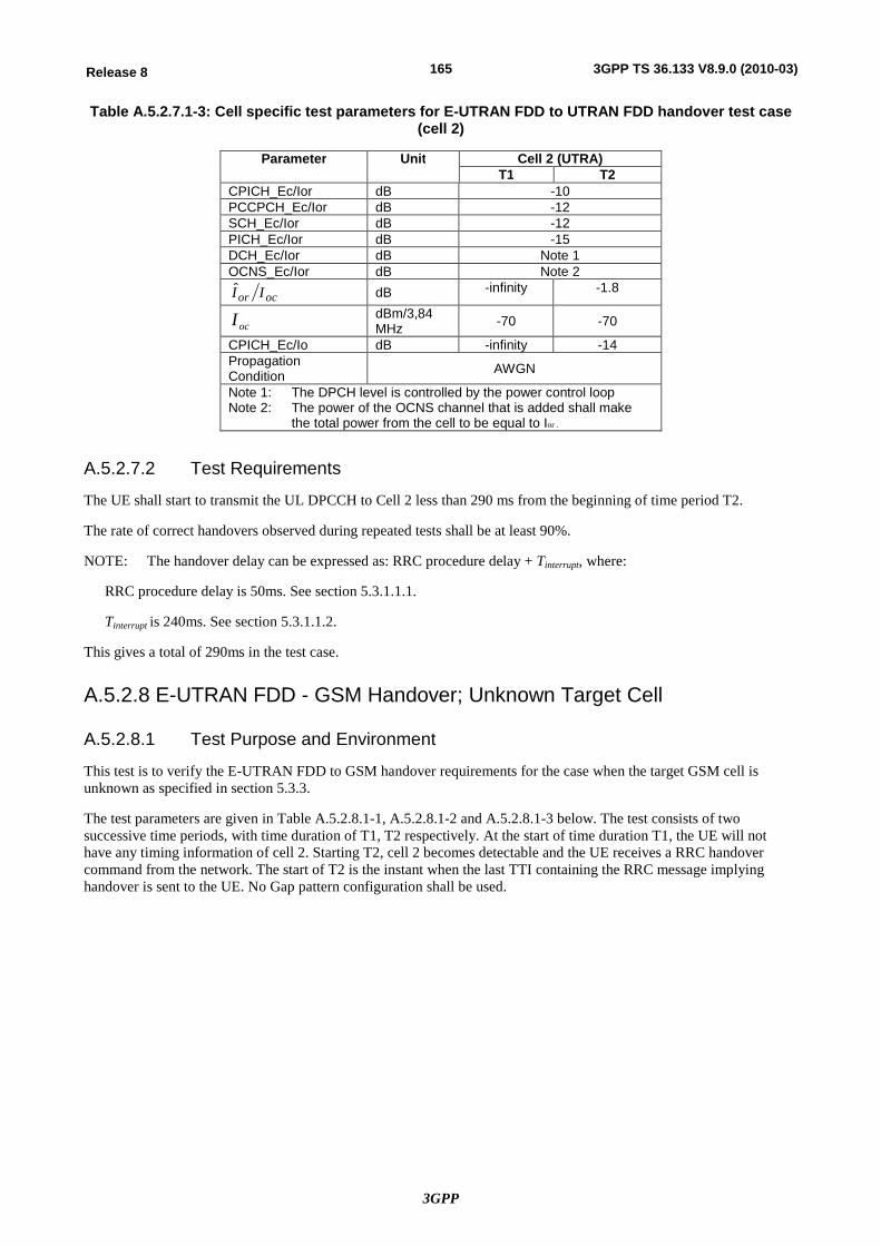
3GPP
165Release 8 3GPP TS 36.133 V8.9.0 (2010-03)
Table A.5.2.7.1-3: Cell specific test parameters for E-UTRAN FDD to UTRAN FDD handover test case (cell 2)
Parameter Unit Cell 2 (UTRA) T1 T2
CPICH_Ec/Ior dB -10 PCCPCH_Ec/Ior dB -12 SCH_Ec/Ior dB -12 PICH_Ec/Ior dB -15 DCH_Ec/Ior dB Note 1 OCNS_Ec/Ior dB Note 2
ocor II dB -infinity -1.8
ocI dBm/3,84 MHz -70 -70
CPICH_Ec/Io dB -infinity -14 Propagation Condition AWGN
Note 1: The DPCH level is controlled by the power control loop Note 2: The power of the OCNS channel that is added shall make
the total power from the cell to be equal to Ior .
A.5.2.7.2 Test Requirements
The UE shall start to transmit the UL DPCCH to Cell 2 less than 290 ms from the beginning of time period T2.
The rate of correct handovers observed during repeated tests shall be at least 90%.
NOTE: The handover delay can be expressed as: RRC procedure delay + Tinterrupt, where:
RRC procedure delay is 50ms. See section 5.3.1.1.1.
Tinterrupt is 240ms. See section 5.3.1.1.2.
This gives a total of 290ms in the test case.
A.5.2.8 E-UTRAN FDD - GSM Handover; Unknown Target Cell
A.5.2.8.1 Test Purpose and Environment
This test is to verify the E-UTRAN FDD to GSM handover requirements for the case when the target GSM cell is unknown as specified in section 5.3.3.
The test parameters are given in Table A.5.2.8.1-1, A.5.2.8.1-2 and A.5.2.8.1-3 below. The test consists of two successive time periods, with time duration of T1, T2 respectively. At the start of time duration T1, the UE will not have any timing information of cell 2. Starting T2, cell 2 becomes detectable and the UE receives a RRC handover command from the network. The start of T2 is the instant when the last TTI containing the RRC message implying handover is sent to the UE. No Gap pattern configuration shall be used.
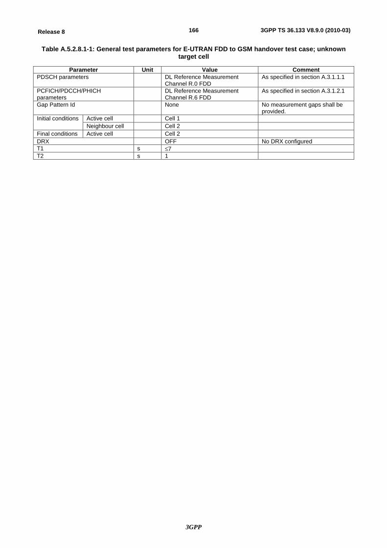
3GPP
166Release 8 3GPP TS 36.133 V8.9.0 (2010-03)
Table A.5.2.8.1-1: General test parameters for E-UTRAN FDD to GSM handover test case; unknown target cell
Parameter Unit Value Comment PDSCH parameters DL Reference Measurement
Channel R.0 FDD As specified in section A.3.1.1.1
PCFICH/PDCCH/PHICH parameters
DL Reference Measurement Channel R.6 FDD
As specified in section A.3.1.2.1
Gap Pattern Id None No measurement gaps shall be provided.
Initial conditions Active cell Cell 1 Neighbour cell Cell 2
Final conditions Active cell Cell 2 DRX OFF No DRX configured T1 s £7 T2 s 1
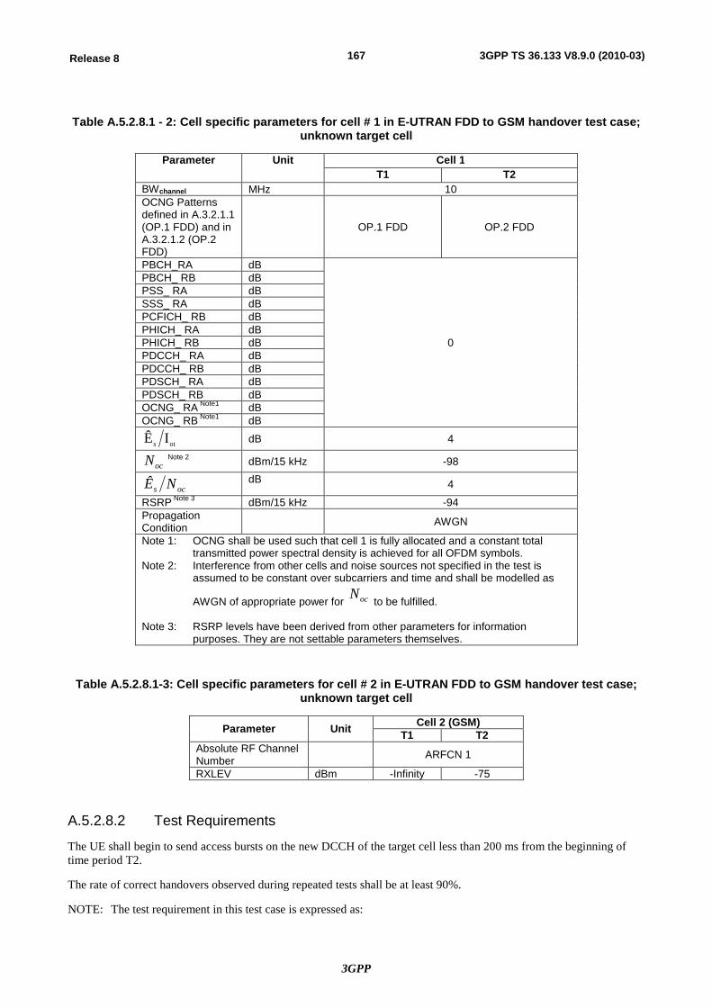
3GPP
167Release 8 3GPP TS 36.133 V8.9.0 (2010-03)
Table A.5.2.8.1 - 2: Cell specific parameters for cell # 1 in E-UTRAN FDD to GSM handover test case; unknown target cell
Parameter Unit Cell 1 T1 T2
BWchannel MHz 10 OCNG Patterns defined in A.3.2.1.1 (OP.1 FDD) and in A.3.2.1.2 (OP.2 FDD)
OP.1 FDD OP.2 FDD
PBCH_RA dB
0
PBCH_ RB dB PSS_ RA dB SSS_ RA dB PCFICH_ RB dB PHICH_ RA dB PHICH_ RB dB PDCCH_ RA dB PDCCH_ RB dB PDSCH_ RA dB PDSCH_ RB dB OCNG_ RA Note1 dB OCNG_ RB Note1 dB
ots IÊ dB 4
ocN Note 2 dBm/15 kHz -98
ocs NÊ dB 4
RSRP Note 3 dBm/15 kHz -94 Propagation Condition
AWGN
Note 1: OCNG shall be used such that cell 1 is fully allocated and a constant total transmitted power spectral density is achieved for all OFDM symbols.
Note 2: Interference from other cells and noise sources not specified in the test is assumed to be constant over subcarriers and time and shall be modelled as
AWGN of appropriate power for ocN to be fulfilled.
Note 3: RSRP levels have been derived from other parameters for information
purposes. They are not settable parameters themselves.
Table A.5.2.8.1-3: Cell specific parameters for cell # 2 in E-UTRAN FDD to GSM handover test case; unknown target cell
Parameter Unit Cell 2 (GSM) T1 T2
Absolute RF Channel Number ARFCN 1
RXLEV dBm -Infinity -75
A.5.2.8.2 Test Requirements
The UE shall begin to send access bursts on the new DCCH of the target cell less than 200 ms from the beginning of time period T2.
The rate of correct handovers observed during repeated tests shall be at least 90%.
NOTE: The test requirement in this test case is expressed as:
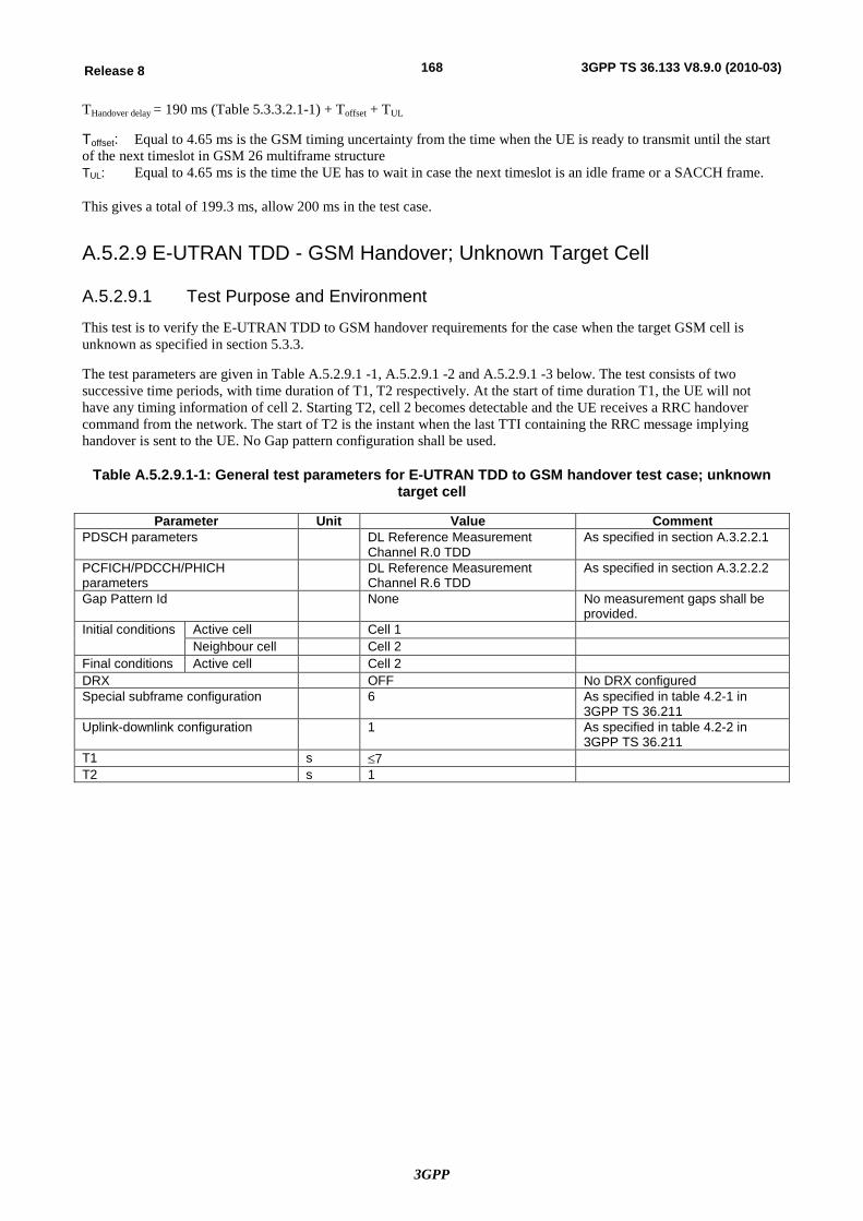
3GPP
168Release 8 3GPP TS 36.133 V8.9.0 (2010-03)
THandover delay = 190 ms (Table 5.3.3.2.1-1) + Toffset + TUL
Toffset: Equal to 4.65 ms is the GSM timing uncertainty from the time when the UE is ready to transmit until the start of the next timeslot in GSM 26 multiframe structure TUL: Equal to 4.65 ms is the time the UE has to wait in case the next timeslot is an idle frame or a SACCH frame.
This gives a total of 199.3 ms, allow 200 ms in the test case.
A.5.2.9 E-UTRAN TDD - GSM Handover; Unknown Target Cell
A.5.2.9.1 Test Purpose and Environment
This test is to verify the E-UTRAN TDD to GSM handover requirements for the case when the target GSM cell is unknown as specified in section 5.3.3.
The test parameters are given in Table A.5.2.9.1 -1, A.5.2.9.1 -2 and A.5.2.9.1 -3 below. The test consists of two successive time periods, with time duration of T1, T2 respectively. At the start of time duration T1, the UE will not have any timing information of cell 2. Starting T2, cell 2 becomes detectable and the UE receives a RRC handover command from the network. The start of T2 is the instant when the last TTI containing the RRC message implying handover is sent to the UE. No Gap pattern configuration shall be used.
Table A.5.2.9.1-1: General test parameters for E-UTRAN TDD to GSM handover test case; unknown target cell
Parameter Unit Value Comment PDSCH parameters DL Reference Measurement
Channel R.0 TDD As specified in section A.3.2.2.1
PCFICH/PDCCH/PHICH parameters
DL Reference Measurement Channel R.6 TDD
As specified in section A.3.2.2.2
Gap Pattern Id None No measurement gaps shall be provided.
Initial conditions Active cell Cell 1 Neighbour cell Cell 2
Final conditions Active cell Cell 2 DRX OFF No DRX configured Special subframe configuration 6 As specified in table 4.2-1 in
3GPP TS 36.211 Uplink-downlink configuration 1 As specified in table 4.2-2 in
3GPP TS 36.211 T1 s £7 T2 s 1
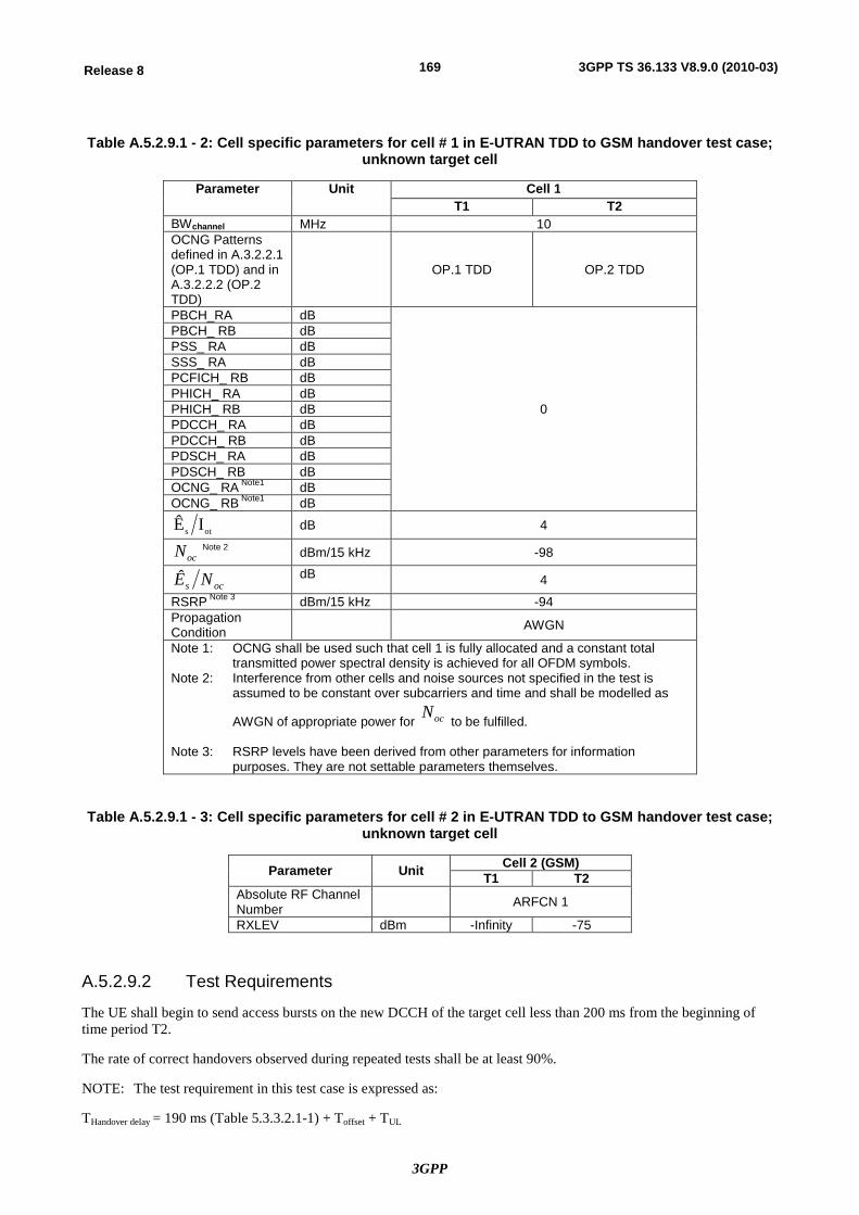
3GPP
169Release 8 3GPP TS 36.133 V8.9.0 (2010-03)
Table A.5.2.9.1 - 2: Cell specific parameters for cell # 1 in E-UTRAN TDD to GSM handover test case; unknown target cell
Parameter Unit Cell 1 T1 T2
BWchannel MHz 10 OCNG Patterns defined in A.3.2.2.1 (OP.1 TDD) and in A.3.2.2.2 (OP.2 TDD)
OP.1 TDD OP.2 TDD
PBCH_RA dB
0
PBCH_ RB dB PSS_ RA dB SSS_ RA dB PCFICH_ RB dB PHICH_ RA dB PHICH_ RB dB PDCCH_ RA dB PDCCH_ RB dB PDSCH_ RA dB PDSCH_ RB dB OCNG_ RA Note1 dB OCNG_ RB Note1 dB
ots IÊ dB 4
ocN Note 2 dBm/15 kHz -98
ocs NÊ dB 4
RSRP Note 3 dBm/15 kHz -94 Propagation Condition
AWGN
Note 1: OCNG shall be used such that cell 1 is fully allocated and a constant total transmitted power spectral density is achieved for all OFDM symbols.
Note 2: Interference from other cells and noise sources not specified in the test is assumed to be constant over subcarriers and time and shall be modelled as
AWGN of appropriate power for ocN to be fulfilled.
Note 3: RSRP levels have been derived from other parameters for information
purposes. They are not settable parameters themselves.
Table A.5.2.9.1 - 3: Cell specific parameters for cell # 2 in E-UTRAN TDD to GSM handover test case; unknown target cell
Parameter Unit Cell 2 (GSM) T1 T2
Absolute RF Channel Number ARFCN 1
RXLEV dBm -Infinity -75
A.5.2.9.2 Test Requirements
The UE shall begin to send access bursts on the new DCCH of the target cell less than 200 ms from the beginning of time period T2.
The rate of correct handovers observed during repeated tests shall be at least 90%.
NOTE: The test requirement in this test case is expressed as:
THandover delay = 190 ms (Table 5.3.3.2.1-1) + Toffset + TUL
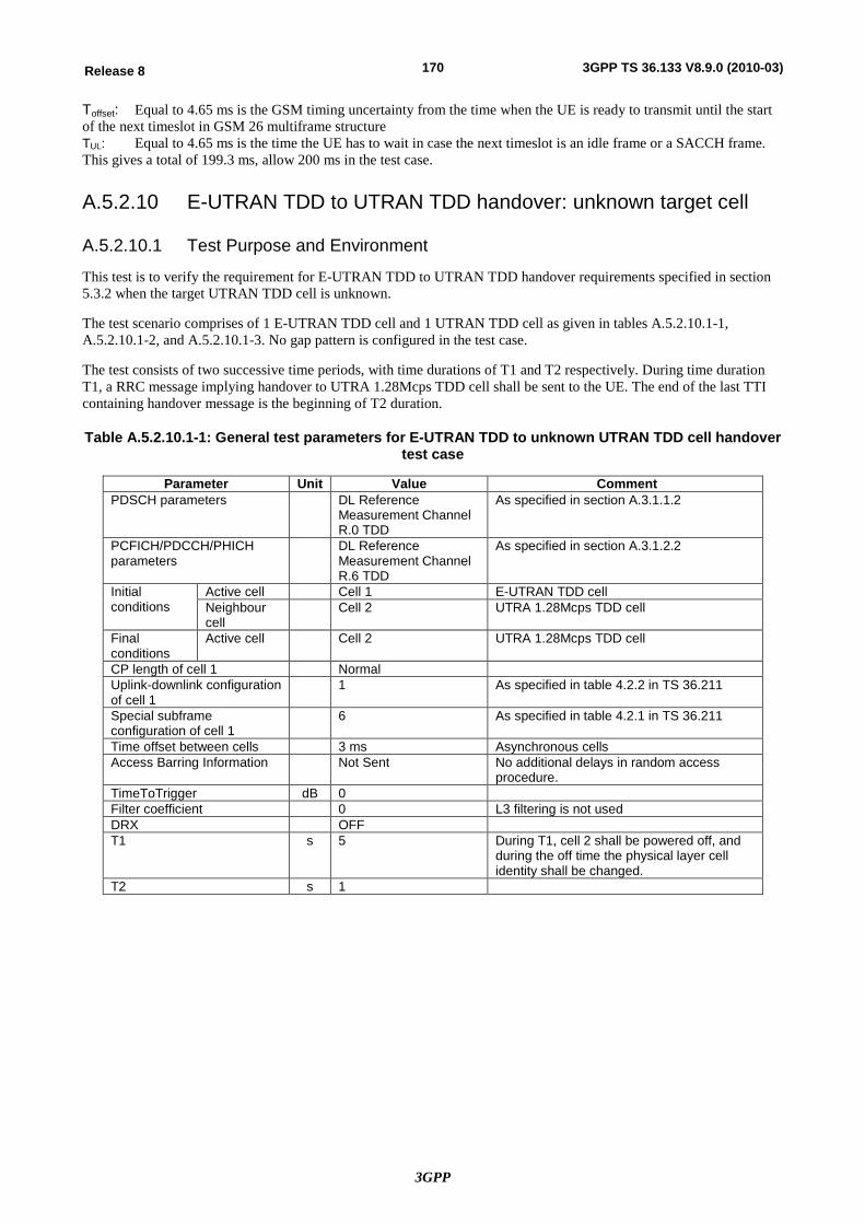
3GPP
170Release 8 3GPP TS 36.133 V8.9.0 (2010-03)
Toffset: Equal to 4.65 ms is the GSM timing uncertainty from the time when the UE is ready to transmit until the start of the next timeslot in GSM 26 multiframe structure TUL: Equal to 4.65 ms is the time the UE has to wait in case the next timeslot is an idle frame or a SACCH frame. This gives a total of 199.3 ms, allow 200 ms in the test case.
A.5.2.10 E-UTRAN TDD to UTRAN TDD handover: unknown target cell
A.5.2.10.1 Test Purpose and Environment
This test is to verify the requirement for E-UTRAN TDD to UTRAN TDD handover requirements specified in section 5.3.2 when the target UTRAN TDD cell is unknown.
The test scenario comprises of 1 E-UTRAN TDD cell and 1 UTRAN TDD cell as given in tables A.5.2.10.1-1, A.5.2.10.1-2, and A.5.2.10.1-3. No gap pattern is configured in the test case.
The test consists of two successive time periods, with time durations of T1 and T2 respectively. During time duration T1, a RRC message implying handover to UTRA 1.28Mcps TDD cell shall be sent to the UE. The end of the last TTI containing handover message is the beginning of T2 duration.
Table A.5.2.10.1-1: General test parameters for E-UTRAN TDD to unknown UTRAN TDD cell handover test case
Parameter Unit Value Comment PDSCH parameters DL Reference
Measurement Channel R.0 TDD
As specified in section A.3.1.1.2
PCFICH/PDCCH/PHICH parameters
DL Reference Measurement Channel R.6 TDD
As specified in section A.3.1.2.2
Initial conditions
Active cell Cell 1 E-UTRAN TDD cell Neighbour cell
Cell 2 UTRA 1.28Mcps TDD cell
Final conditions
Active cell Cell 2 UTRA 1.28Mcps TDD cell
CP length of cell 1 Normal Uplink-downlink configuration of cell 1
1 As specified in table 4.2.2 in TS 36.211
Special subframe configuration of cell 1
6 As specified in table 4.2.1 in TS 36.211
Time offset between cells 3 ms Asynchronous cells Access Barring Information Not Sent No additional delays in random access
procedure. TimeToTrigger dB 0 Filter coefficient 0 L3 filtering is not used DRX OFF T1 s 5 During T1, cell 2 shall be powered off, and
during the off time the physical layer cell identity shall be changed.
T2 s 1
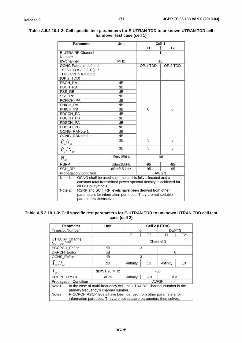
3GPP
171Release 8 3GPP TS 36.133 V8.9.0 (2010-03)
Table A.5.2.10.1-2: Cell specific test parameters for E-UTRAN TDD to unknown UTRAN TDD cell handover test case (cell 1)
Parameter Unit Cell 1 T1 T2
E-UTRA RF Channel Number
1
BWchannel MHz 10 OCNG Patterns defined in TS36.133 A.3.2.2.1 (OP.1 TDD) and in A.3.2.2.2 (OP.2 TDD)
OP.1 TDD OP.2 TDD
PBCH_RA dB
0 0
PBCH_RB dB PSS_RB dB SSS_RB dB PCFICH_PA dB PHICH_PA dB PHICH_PB dB PDCCH_PA dB PDCCH_PB dB PDSCH_PA dB PDSCH_PB dB OCNG_RANote 1 dB OCNG_RBNote 1 dB
ots IÊ
dB 3 3
ocs NÊ dB 3 3
ocN
dBm/15kHz -98
RSRP dBm/15kHz -95 -95 SCH_RP dBm/15 kHz -95 -95 Propagation Condition AWGN Note 1: OCNG shall be used such that cell is fully allocated and a
constant total transmitted power spectral density is achieved for all OFDM symbols.
Note 2: RSRP and SCH_RP levels have been derived from other parameters for information purposes. They are not settable parameters themselves.
Table A.5.2.10.1-3: Cell specific test parameters for E-UTRAN TDD to unknown UTRAN TDD cell test case (cell 2)
Parameter Unit Cell 2 (UTRA) Timeslot Number 0 DwPTS T1 T2 T1 T2 UTRA RF Channel NumberNote1 Channel 2
PCCPCH_Ec/Ior dB -3 DwPCH_Ec/Ior dB 0 OCNS_Ec/Ior dB -3
ocor II
dB -infinity 13 -infinity 13
ocI dBm/1.28 MHz -80
PCCPCH RSCP dBm -infinity -70 n.a. Propagation Condition AWGN Note1: In the case of multi-frequency cell, the UTRA RF Channel Number is the
primary frequency’s channel number. Note2: P-CCPCH RSCP levels have been derived from other parameters for
information purposes. They are not settable parameters themselves.
3GPP
172Release 8 3GPP TS 36.133 V8.9.0 (2010-03)
A.5.2.10.2 Test Requirements
The UE shall start to transmit the SYNCH-UL sequence in the UpPTS to Cell 2 less than [280] ms from the beginning of time period T2.
The rate of correct handovers observed during repeated tests shall be at least 90%.
A.5.3 E-UTRAN Handover to Non-3GPP RATs
A.5.3.1 E-UTRAN FDD – HRPD Handover
A.5.3.1.1 Test Purpose and Environment
This test is to verify the requirement for the E-UTRAN FDD to HRPD handover requirements specified in section 5.4.1.
The test parameters are given in Tables A.5.3.1.1-1, A.5.3.1.1-2 and A.5.3.1.1-3. The test consists of three successive time periods, with time durations of T1, T2 and T3 respectively. At the start of time duration T1, the UE does not have any timing information of Cell 2. Starting T2, Cell 2 becomes detectable and the UE is expected to detect and send a measurement report. Gap pattern configuration with id #0 as specified in Table 8.1.2.1-1 is configured before T2 begins to enable inter-RAT frequency monitoring.
A RRC message implying handover shall be sent to the UE during period T2, after the UE has reported Event B2. The start of T3 is the instant when the last TTI containing the RRC message implying handover is sent to the UE. The handover message shall contain cell 2 as the target cell.
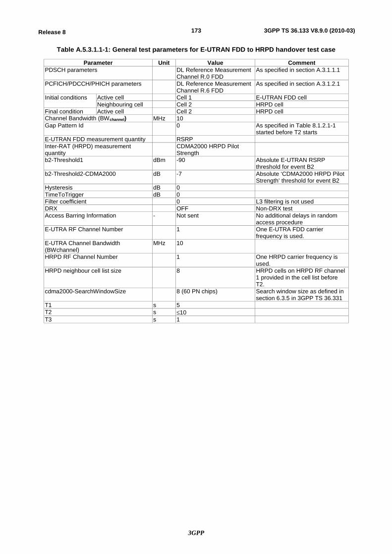
3GPP
173Release 8 3GPP TS 36.133 V8.9.0 (2010-03)
Table A.5.3.1.1-1: General test parameters for E-UTRAN FDD to HRPD handover test case
Parameter Unit Value Comment PDSCH parameters DL Reference Measurement
Channel R.0 FDD As specified in section A.3.1.1.1
PCFICH/PDCCH/PHICH parameters DL Reference Measurement Channel R.6 FDD
As specified in section A.3.1.2.1
Initial conditions Active cell Cell 1 E-UTRAN FDD cell Neighbouring cell Cell 2 HRPD cell
Final condition Active cell Cell 2 HRPD cell Channel Bandwidth (BWchannel) MHz 10 Gap Pattern Id 0 As specified in Table 8.1.2.1-1
started before T2 starts E-UTRAN FDD measurement quantity RSRP Inter-RAT (HRPD) measurement quantity
CDMA2000 HRPD Pilot Strength
b2-Threshold1 dBm -90 Absolute E-UTRAN RSRP threshold for event B2
b2-Threshold2-CDMA2000 dB -7 Absolute ‘CDMA2000 HRPD Pilot Strength’ threshold for event B2
Hysteresis dB 0 TimeToTrigger dB 0 Filter coefficient 0 L3 filtering is not used DRX OFF Non-DRX test Access Barring Information - Not sent No additional delays in random
access procedure E-UTRA RF Channel Number 1 One E-UTRA FDD carrier
frequency is used. E-UTRA Channel Bandwidth (BWchannel)
MHz 10
HRPD RF Channel Number 1 One HRPD carrier frequency is used.
HRPD neighbour cell list size 8 HRPD cells on HRPD RF channel 1 provided in the cell list before T2.
cdma2000-SearchWindowSize 8 (60 PN chips) Search window size as defined in section 6.3.5 in 3GPP TS 36.331
T1 s 5 T2 s £10 T3 s 1

3GPP
174Release 8 3GPP TS 36.133 V8.9.0 (2010-03)
Table A.5.3.1.1-2: Cell specific test parameters for E-UTRAN FDD cell#1 for handover to HRPD cell # 2
Parameter Unit Cell 1 (E-UTRA) T1 T2 T3
E-UTRA RF Channel number
1
BWchannel MHz 10 OCNG Patterns defined in A.3.2.1.1 (OP.1 FDD) and in A.3.2.1.2 (OP.2 FDD)
OP.1 FDD OP.2 FDD
PBCH_RA dB
0
PBCH_RB dB PSS_RA dB SSS_RA dB PCFICH_RB dB PHICH_RA dB PHICH_RB dB PDCCH_RA dB PDCCH_RB dB PDSCH_RA dB PDSCH_RB dB OCNG_RANote 1 dB OCNG_RBNote 1 dB
ocN Note 2 dBm/15 kHz
-98
RSRP Note 3 dBm/15 KHz
-98 -98 -98
ocs NÊ dB 0 0 0
ots IÊ dB 0 0 0
Propagation Condition AWGN Note 1: OCNG shall be used such that both cells are fully allocated and a
constant total transmitted power spectral density is achieved for all OFDM symbols.
Note 2: Interference from other cells and noise sources not specified in the test is assumed to be constant over subcarriers and time and shall
be modelled as AWGN of appropriate power for ocN to be fulfilled.
Note 3: RSRP levels have been derived from other parameters for information purposes. They are not settable parameters themselves.
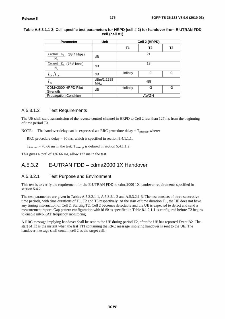
3GPP
175Release 8 3GPP TS 36.133 V8.9.0 (2010-03)
Table A.5.3.1.1-3: Cell specific test parameters for HRPD (cell # 2) for handover from E-UTRAN FDD cell (cell #1)
Parameter Unit Cell 2 (HRPD) T1 T2 T3
t
b
NE Control (38.4 kbps)
dB 21
t
b
NE Control (76.8 kbps)
dB 18
ocor II dB -infinity 0 0
ocI dBm/1.2288 MHz -55
CDMA2000 HRPD Pilot Strength dB -infinity -3 -3
Propagation Condition AWGN
A.5.3.1.2 Test Requirements
The UE shall start transmission of the reverse control channel in HRPD to Cell 2 less than 127 ms from the beginning of time period T3.
NOTE: The handover delay can be expressed as: RRC procedure delay + Tinterrupt, where:
RRC procedure delay = 50 ms, which is specified in section 5.4.1.1.1.
Tinterrupt = 76.66 ms in the test; Tinterrupt is defined in section 5.4.1.1.2.
This gives a total of 126.66 ms, allow 127 ms in the test.
A.5.3.2 E-UTRAN FDD – cdma2000 1X Handover
A.5.3.2.1 Test Purpose and Environment
This test is to verify the requirement for the E-UTRAN FDD to cdma2000 1X handover requirements specified in section 5.4.2.
The test parameters are given in Tables A.5.3.2.1-1, A.5.3.2.1-2 and A.5.3.2.1-3. The test consists of three successive time periods, with time durations of T1, T2 and T3 respectively. At the start of time duration T1, the UE does not have any timing information of Cell 2. Starting T2, Cell 2 becomes detectable and the UE is expected to detect and send a measurement report. Gap pattern configuration with id #0 as specified in Table 8.1.2.1-1 is configured before T2 begins to enable inter-RAT frequency monitoring.
A RRC message implying handover shall be sent to the UE during period T2, after the UE has reported Event B2. The start of T3 is the instant when the last TTI containing the RRC message implying handover is sent to the UE. The handover message shall contain cell 2 as the target cell.
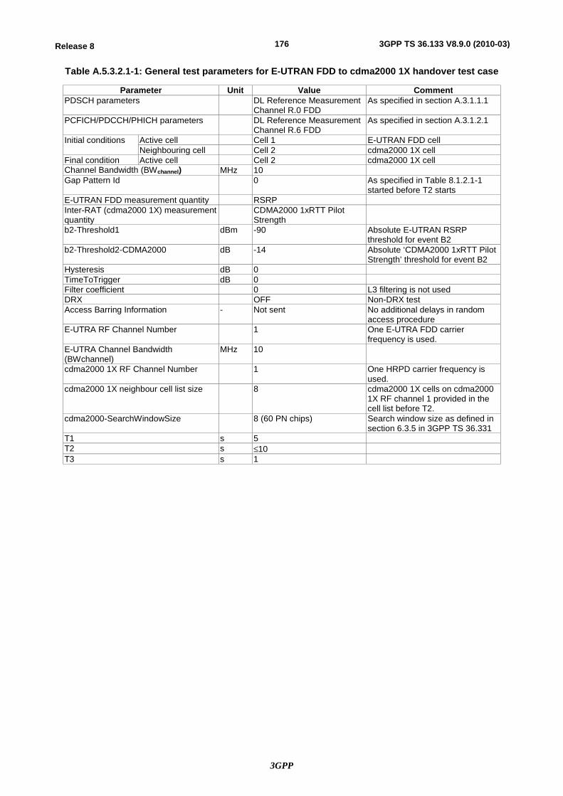
3GPP
176Release 8 3GPP TS 36.133 V8.9.0 (2010-03)
Table A.5.3.2.1-1: General test parameters for E-UTRAN FDD to cdma2000 1X handover test case
Parameter Unit Value Comment PDSCH parameters DL Reference Measurement
Channel R.0 FDD As specified in section A.3.1.1.1
PCFICH/PDCCH/PHICH parameters DL Reference Measurement Channel R.6 FDD
As specified in section A.3.1.2.1
Initial conditions Active cell Cell 1 E-UTRAN FDD cell Neighbouring cell Cell 2 cdma2000 1X cell
Final condition Active cell Cell 2 cdma2000 1X cell Channel Bandwidth (BWchannel) MHz 10 Gap Pattern Id 0 As specified in Table 8.1.2.1-1
started before T2 starts E-UTRAN FDD measurement quantity RSRP Inter-RAT (cdma2000 1X) measurement quantity
CDMA2000 1xRTT Pilot Strength
b2-Threshold1 dBm -90 Absolute E-UTRAN RSRP threshold for event B2
b2-Threshold2-CDMA2000 dB -14 Absolute ‘CDMA2000 1xRTT Pilot Strength’ threshold for event B2
Hysteresis dB 0 TimeToTrigger dB 0 Filter coefficient 0 L3 filtering is not used DRX OFF Non-DRX test Access Barring Information - Not sent No additional delays in random
access procedure E-UTRA RF Channel Number 1 One E-UTRA FDD carrier
frequency is used. E-UTRA Channel Bandwidth (BWchannel)
MHz 10
cdma2000 1X RF Channel Number 1 One HRPD carrier frequency is used.
cdma2000 1X neighbour cell list size 8 cdma2000 1X cells on cdma2000 1X RF channel 1 provided in the cell list before T2.
cdma2000-SearchWindowSize 8 (60 PN chips) Search window size as defined in section 6.3.5 in 3GPP TS 36.331
T1 s 5 T2 s £10 T3 s 1
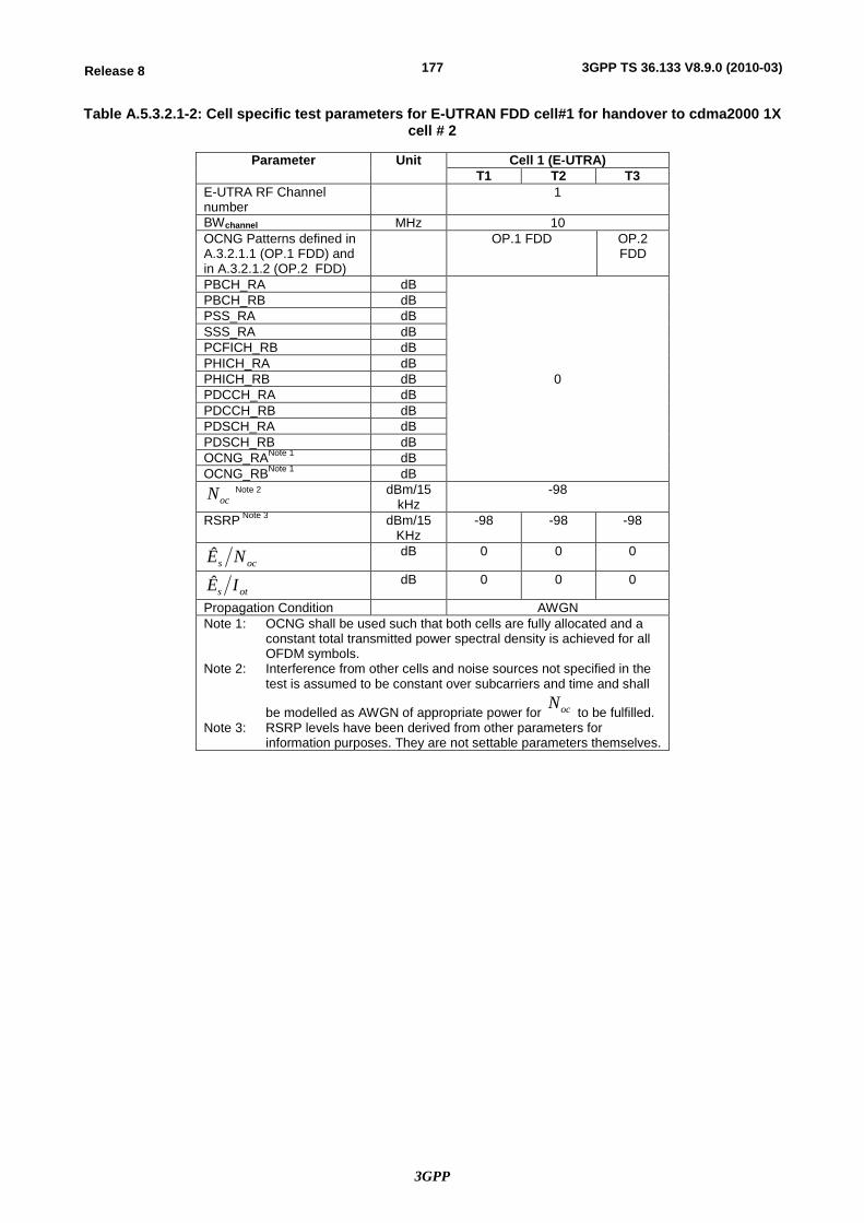
3GPP
177Release 8 3GPP TS 36.133 V8.9.0 (2010-03)
Table A.5.3.2.1-2: Cell specific test parameters for E-UTRAN FDD cell#1 for handover to cdma2000 1X cell # 2
Parameter Unit Cell 1 (E-UTRA) T1 T2 T3
E-UTRA RF Channel number
1
BWchannel MHz 10 OCNG Patterns defined in A.3.2.1.1 (OP.1 FDD) and in A.3.2.1.2 (OP.2 FDD)
OP.1 FDD OP.2 FDD
PBCH_RA dB
0
PBCH_RB dB PSS_RA dB SSS_RA dB PCFICH_RB dB PHICH_RA dB PHICH_RB dB PDCCH_RA dB PDCCH_RB dB PDSCH_RA dB PDSCH_RB dB OCNG_RANote 1 dB OCNG_RBNote 1 dB
ocN Note 2 dBm/15 kHz
-98
RSRP Note 3 dBm/15 KHz
-98 -98 -98
ocs NÊ dB 0 0 0
ots IÊ dB 0 0 0
Propagation Condition AWGN Note 1: OCNG shall be used such that both cells are fully allocated and a
constant total transmitted power spectral density is achieved for all OFDM symbols.
Note 2: Interference from other cells and noise sources not specified in the test is assumed to be constant over subcarriers and time and shall
be modelled as AWGN of appropriate power for ocN to be fulfilled.
Note 3: RSRP levels have been derived from other parameters for information purposes. They are not settable parameters themselves.
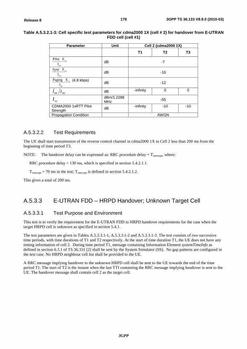
3GPP
178Release 8 3GPP TS 36.133 V8.9.0 (2010-03)
Table A.5.3.2.1-3: Cell specific test parameters for cdma2000 1X (cell # 2) for handover from E-UTRAN FDD cell (cell #1)
Parameter Unit Cell 2 (cdma2000 1X) T1 T2 T3
or
c
IEPilot
dB -7
or
c
IE Sync
dB -16
or
c
IE Paging (4.8 kbps)
dB -12
ocor II dB -infinity 0 0
ocI dBm/1.2288 MHz -55
CDMA2000 1xRTT Pilot Strength dB -infinity -10 -10
Propagation Condition AWGN
A.5.3.2.2 Test Requirements
The UE shall start transmission of the reverse control channel in cdma2000 1X to Cell 2 less than 200 ms from the beginning of time period T3.
NOTE: The handover delay can be expressed as: RRC procedure delay + Tinterrupt, where:
RRC procedure delay = 130 ms, which is specified in section 5.4.2.1.1.
Tinterrupt = 70 ms in the test; Tinterrupt is defined in section 5.4.2.1.2.
This gives a total of 200 ms.
A.5.3.3 E-UTRAN FDD – HRPD Handover; Unknown Target Cell
A.5.3.3.1 Test Purpose and Environment
This test is to verify the requirement for the E-UTRAN FDD to HRPD handover requirements for the case when the target HRPD cell is unknown as specified in section 5.4.1.
The test parameters are given in Tables A.5.3.3.1-1, A.5.3.3.1-2 and A.5.3.3.1-3. The test consists of two successive time periods, with time durations of T1 and T2 respectively. At the start of time duration T1, the UE does not have any timing information of cell 2. During time period T1, message containing Information Element systemTimeInfo as defined in section 6.3.1 of TS 36.331 [2] shall be sent by the System Simulator (SS). No gap patterns are configured in the test case. No HRPD neighbour cell list shall be provided to the UE.
A RRC message implying handover to the unknown HRPD cell shall be sent to the UE towards the end of the time period T1. The start of T2 is the instant when the last TTI containing the RRC message implying handover is sent to the UE. The handover message shall contain cell 2 as the target cell.
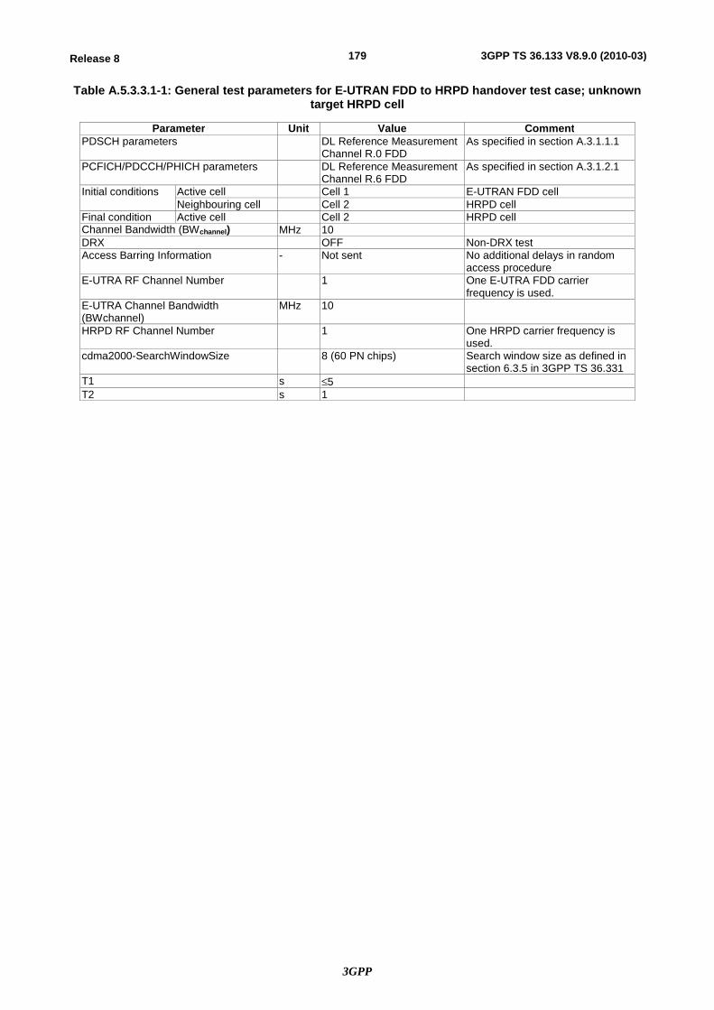
3GPP
179Release 8 3GPP TS 36.133 V8.9.0 (2010-03)
Table A.5.3.3.1-1: General test parameters for E-UTRAN FDD to HRPD handover test case; unknown target HRPD cell
Parameter Unit Value Comment PDSCH parameters DL Reference Measurement
Channel R.0 FDD As specified in section A.3.1.1.1
PCFICH/PDCCH/PHICH parameters DL Reference Measurement Channel R.6 FDD
As specified in section A.3.1.2.1
Initial conditions Active cell Cell 1 E-UTRAN FDD cell Neighbouring cell Cell 2 HRPD cell
Final condition Active cell Cell 2 HRPD cell Channel Bandwidth (BWchannel) MHz 10 DRX OFF Non-DRX test Access Barring Information - Not sent No additional delays in random
access procedure E-UTRA RF Channel Number 1 One E-UTRA FDD carrier
frequency is used. E-UTRA Channel Bandwidth (BWchannel)
MHz 10
HRPD RF Channel Number 1 One HRPD carrier frequency is used.
cdma2000-SearchWindowSize 8 (60 PN chips) Search window size as defined in section 6.3.5 in 3GPP TS 36.331
T1 s £5 T2 s 1
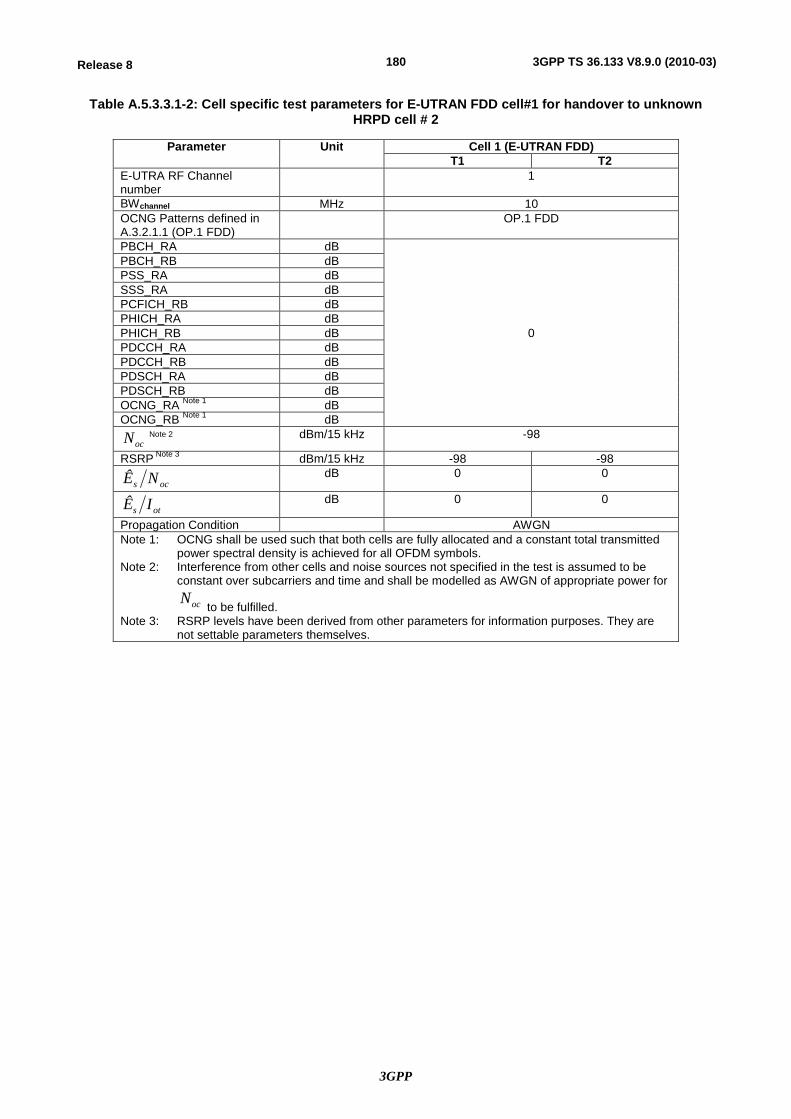
3GPP
180Release 8 3GPP TS 36.133 V8.9.0 (2010-03)
Table A.5.3.3.1-2: Cell specific test parameters for E-UTRAN FDD cell#1 for handover to unknown HRPD cell # 2
Parameter Unit Cell 1 (E-UTRAN FDD) T1 T2
E-UTRA RF Channel number
1
BWchannel MHz 10 OCNG Patterns defined in A.3.2.1.1 (OP.1 FDD)
OP.1 FDD
PBCH_RA dB
0
PBCH_RB dB PSS_RA dB SSS_RA dB PCFICH_RB dB PHICH_RA dB PHICH_RB dB PDCCH_RA dB PDCCH_RB dB PDSCH_RA dB PDSCH_RB dB OCNG_RA Note 1 dB OCNG_RB Note 1 dB
ocN Note 2 dBm/15 kHz -98
RSRP Note 3 dBm/15 kHz -98 -98
ocs NÊ dB 0 0
ots IÊ dB 0 0
Propagation Condition AWGN Note 1: OCNG shall be used such that both cells are fully allocated and a constant total transmitted
power spectral density is achieved for all OFDM symbols. Note 2: Interference from other cells and noise sources not specified in the test is assumed to be
constant over subcarriers and time and shall be modelled as AWGN of appropriate power for
ocN to be fulfilled.
Note 3: RSRP levels have been derived from other parameters for information purposes. They are not settable parameters themselves.
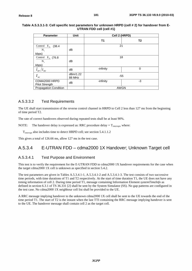
3GPP
181Release 8 3GPP TS 36.133 V8.9.0 (2010-03)
Table A.5.3.3.1-3: Cell specific test parameters for unknown HRPD (cell # 2) for handover from E-UTRAN FDD cell (cell #1)
Parameter Unit Cell 2 (HRPD) T1 T2
t
b
NE Control (38.4
kbps) dB
21
t
b
NE Control (76.8
kbps) dB
18
ocor II dB -infinity 0
ocI dBm/1.2288 MHz -55
CDMA2000 HRPD Pilot Strength dB -infinity -3
Propagation Condition AWGN
A.5.3.3.2 Test Requirements
The UE shall start transmission of the reverse control channel in HRPD to Cell 2 less than 127 ms from the beginning of time period T2.
The rate of correct handovers observed during repeated tests shall be at least 90%.
NOTE: The handover delay is expressed as: RRC procedure delay + Tinterrupt, where:
Tinterrupt also includes time to detect HRPD cell; see section 5.4.1.1.2
This gives a total of 126.66 ms, allow 127 ms in the test case.
A.5.3.4 E-UTRAN FDD – cdma2000 1X Handover; Unknown Target cell
A.5.3.4.1 Test Purpose and Environment
This test is to verify the requirement for the E-UTRAN FDD to cdma2000 1X handover requirements for the case when the target cdma2000 1X cell is unknown as specified in section 5.4.2.
The test parameters are given in Tables A.5.3.4.1-1, A.5.3.4.1-2 and A.5.3.4.1-3. The test consists of two successive time periods, with time durations of T1 and T2 respectively. At the start of time duration T1, the UE does not have any timing information of cell 2. During time period T1, message containing Information Element systemTimeInfo as defined in section 6.3.1 of TS 36.331 [2] shall be sent by the System Simulator (SS). No gap patterns are configured in the test case. No cdma2000 1X neighbour cell list shall be provided to the UE.
A RRC message implying handover to the unknown cdma2000 1X cell shall be sent to the UE towards the end of the time period T1. The start of T2 is the instant when the last TTI containing the RRC message implying handover is sent to the UE. The handover message shall contain cell 2 as the target cell.
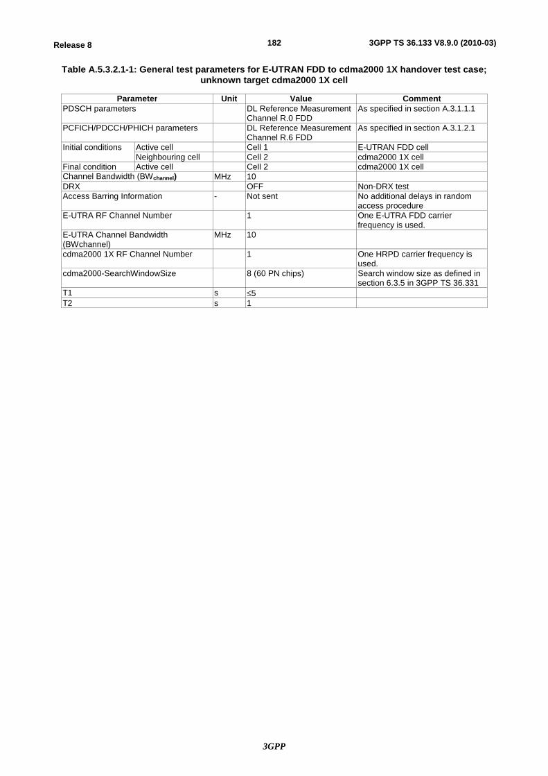
3GPP
182Release 8 3GPP TS 36.133 V8.9.0 (2010-03)
Table A.5.3.2.1-1: General test parameters for E-UTRAN FDD to cdma2000 1X handover test case; unknown target cdma2000 1X cell
Parameter Unit Value Comment PDSCH parameters DL Reference Measurement
Channel R.0 FDD As specified in section A.3.1.1.1
PCFICH/PDCCH/PHICH parameters DL Reference Measurement Channel R.6 FDD
As specified in section A.3.1.2.1
Initial conditions Active cell Cell 1 E-UTRAN FDD cell Neighbouring cell Cell 2 cdma2000 1X cell
Final condition Active cell Cell 2 cdma2000 1X cell Channel Bandwidth (BWchannel) MHz 10 DRX OFF Non-DRX test Access Barring Information - Not sent No additional delays in random
access procedure E-UTRA RF Channel Number 1 One E-UTRA FDD carrier
frequency is used. E-UTRA Channel Bandwidth (BWchannel)
MHz 10
cdma2000 1X RF Channel Number 1 One HRPD carrier frequency is used.
cdma2000-SearchWindowSize 8 (60 PN chips) Search window size as defined in section 6.3.5 in 3GPP TS 36.331
T1 s £5 T2 s 1
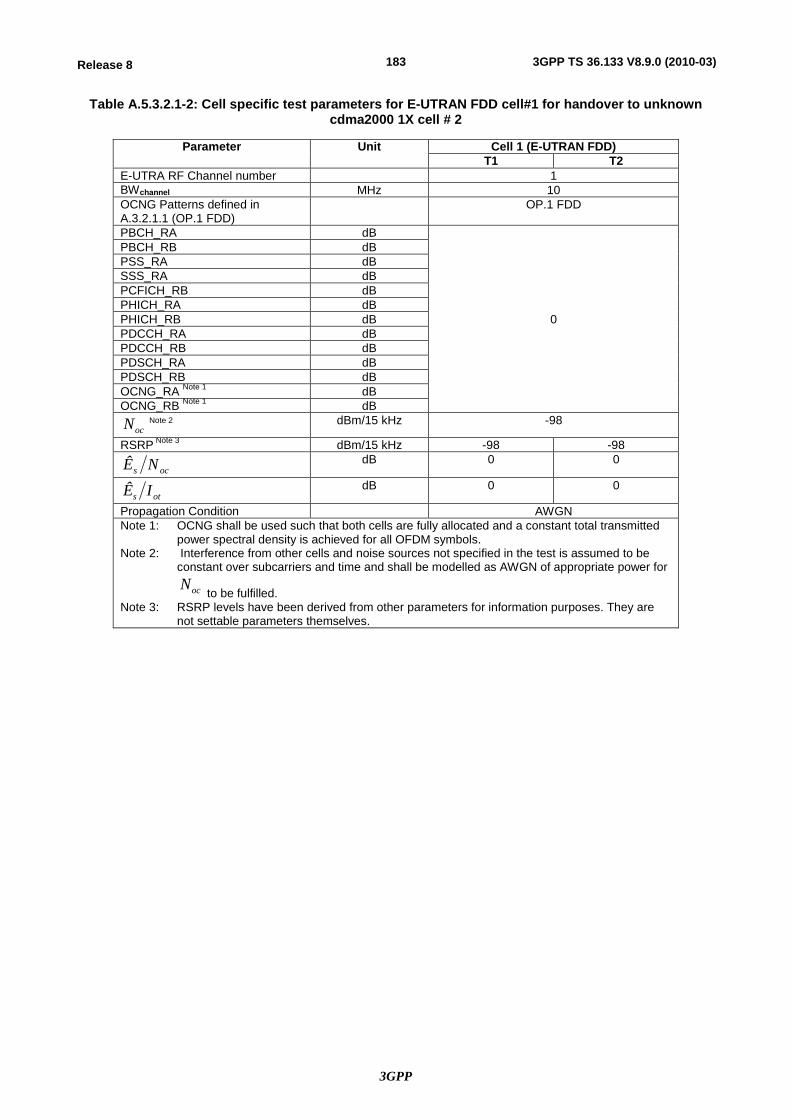
3GPP
183Release 8 3GPP TS 36.133 V8.9.0 (2010-03)
Table A.5.3.2.1-2: Cell specific test parameters for E-UTRAN FDD cell#1 for handover to unknown cdma2000 1X cell # 2
Parameter Unit Cell 1 (E-UTRAN FDD) T1 T2
E-UTRA RF Channel number 1 BWchannel MHz 10 OCNG Patterns defined in A.3.2.1.1 (OP.1 FDD)
OP.1 FDD
PBCH_RA dB
0
PBCH_RB dB PSS_RA dB SSS_RA dB PCFICH_RB dB PHICH_RA dB PHICH_RB dB PDCCH_RA dB PDCCH_RB dB PDSCH_RA dB PDSCH_RB dB OCNG_RA Note 1 dB OCNG_RB Note 1 dB
ocN Note 2 dBm/15 kHz -98
RSRP Note 3 dBm/15 kHz -98 -98
ocs NÊ dB 0 0
ots IÊ dB 0 0
Propagation Condition AWGN Note 1: OCNG shall be used such that both cells are fully allocated and a constant total transmitted
power spectral density is achieved for all OFDM symbols. Note 2: Interference from other cells and noise sources not specified in the test is assumed to be
constant over subcarriers and time and shall be modelled as AWGN of appropriate power for
ocN to be fulfilled.
Note 3: RSRP levels have been derived from other parameters for information purposes. They are not settable parameters themselves.
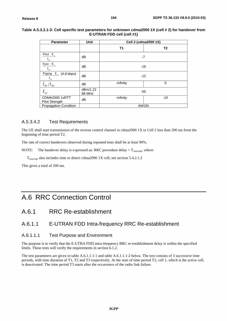
3GPP
184Release 8 3GPP TS 36.133 V8.9.0 (2010-03)
Table A.5.3.2.1-3: Cell specific test parameters for unknown cdma2000 1X (cell # 2) for handover from E-UTRAN FDD cell (cell #1)
Parameter Unit Cell 2 (cdma2000 1X) T1 T2
or
c
IEPilot
dB -7
or
c
IE Sync
dB -16
or
c
IE Paging (4.8 kbps)
dB -12
ocor II dB -infinity 0
ocI dBm/1.2288 MHz -55
CDMA2000 1xRTT Pilot Strength dB -infinity -10
Propagation Condition AWGN
A.5.3.4.2 Test Requirements
The UE shall start transmission of the reverse control channel in cdma2000 1X to Cell 2 less than 200 ms from the beginning of time period T2.
The rate of correct handovers observed during repeated tests shall be at least 90%.
NOTE: The handover delay is expressed as: RRC procedure delay + Tinterrupt, where:
Tinterrupt also includes time to detect cdma2000 1X cell; see section 5.4.2.1.2
This gives a total of 200 ms.
A.6 RRC Connection Control
A.6.1 RRC Re-establishment
A.6.1.1 E-UTRAN FDD Intra-frequency RRC Re-establishment
A.6.1.1.1 Test Purpose and Environment
The purpose is to verify that the E-UTRA FDD intra-frequency RRC re-establishment delay is within the specified limits. These tests will verify the requirements in section 6.1.2.
The test parameters are given in table A.6.1.1.1-1 and table A.6.1.1.1-2 below. The test consists of 3 successive time periods, with time duration of T1, T2 and T3 respectively. At the start of time period T2, cell 1, which is the active cell, is deactivated. The time period T3 starts after the occurrence of the radio link failure.
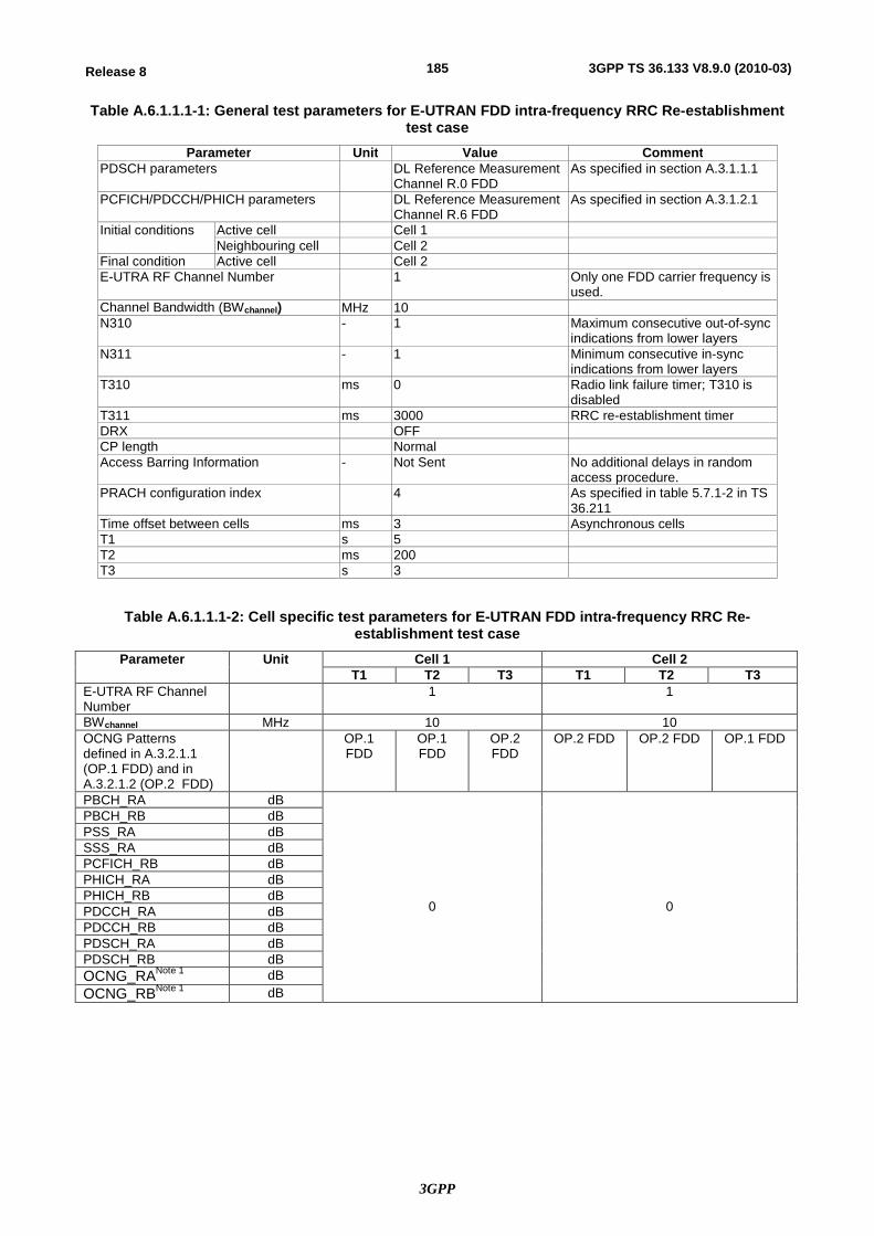
3GPP
185Release 8 3GPP TS 36.133 V8.9.0 (2010-03)
Table A.6.1.1.1-1: General test parameters for E-UTRAN FDD intra-frequency RRC Re-establishment test case
Parameter Unit Value Comment PDSCH parameters DL Reference Measurement
Channel R.0 FDD As specified in section A.3.1.1.1
PCFICH/PDCCH/PHICH parameters DL Reference Measurement Channel R.6 FDD
As specified in section A.3.1.2.1
Initial conditions Active cell Cell 1 Neighbouring cell Cell 2
Final condition Active cell Cell 2 E-UTRA RF Channel Number 1 Only one FDD carrier frequency is
used. Channel Bandwidth (BWchannel) MHz 10 N310 - 1 Maximum consecutive out-of-sync
indications from lower layers N311 - 1 Minimum consecutive in-sync
indications from lower layers T310 ms 0 Radio link failure timer; T310 is
disabled T311 ms 3000 RRC re-establishment timer DRX OFF CP length Normal Access Barring Information - Not Sent No additional delays in random
access procedure. PRACH configuration index 4 As specified in table 5.7.1-2 in TS
36.211 Time offset between cells ms 3 Asynchronous cells T1 s 5 T2 ms 200 T3 s 3
Table A.6.1.1.1-2: Cell specific test parameters for E-UTRAN FDD intra-frequency RRC Re-establishment test case
Parameter Unit Cell 1 Cell 2 T1 T2 T3 T1 T2 T3
E-UTRA RF Channel Number
1 1
BWchannel MHz 10 10 OCNG Patterns defined in A.3.2.1.1 (OP.1 FDD) and in A.3.2.1.2 (OP.2 FDD)
OP.1 FDD
OP.1 FDD
OP.2 FDD
OP.2 FDD OP.2 FDD OP.1 FDD
PBCH_RA dB
0
0
PBCH_RB dB PSS_RA dB SSS_RA dB PCFICH_RB dB PHICH_RA dB PHICH_RB dB PDCCH_RA dB PDCCH_RB dB PDSCH_RA dB PDSCH_RB dB OCNG_RANote 1 dB OCNG_RBNote 1 dB
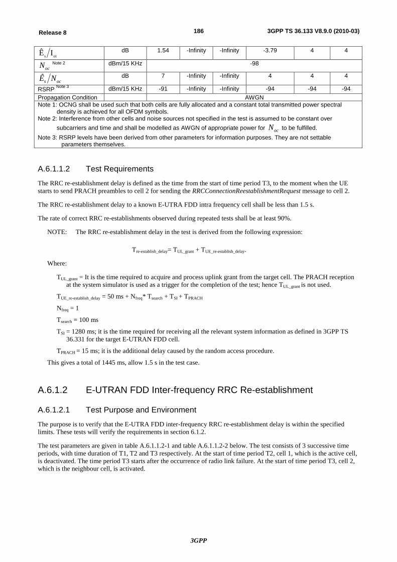
3GPP
186Release 8 3GPP TS 36.133 V8.9.0 (2010-03)
ots IÊ dB 1.54 -Infinity -Infinity -3.79 4 4
ocN Note 2 dBm/15 KHz -98
ocs NÊ dB 7 -Infinity -Infinity 4 4 4
RSRP Note 3 dBm/15 KHz -91 -Infinity -Infinity -94 -94 -94 Propagation Condition AWGN Note 1: OCNG shall be used such that both cells are fully allocated and a constant total transmitted power spectral
density is achieved for all OFDM symbols. Note 2: Interference from other cells and noise sources not specified in the test is assumed to be constant over
subcarriers and time and shall be modelled as AWGN of appropriate power for ocN to be fulfilled. Note 3: RSRP levels have been derived from other parameters for information purposes. They are not settable
parameters themselves.
A.6.1.1.2 Test Requirements
The RRC re-establishment delay is defined as the time from the start of time period T3, to the moment when the UE starts to send PRACH preambles to cell 2 for sending the RRCConnectionReestablishmentRequest message to cell 2.
The RRC re-establishment delay to a known E-UTRA FDD intra frequency cell shall be less than 1.5 s.
The rate of correct RRC re-establishments observed during repeated tests shall be at least 90%.
NOTE: The RRC re-establishment delay in the test is derived from the following expression:
Tre-establish_delay= TUL_grant + TUE_re-establish_delay.
Where:
TUL_grant = It is the time required to acquire and process uplink grant from the target cell. The PRACH reception at the system simulator is used as a trigger for the completion of the test; hence TUL_grant is not used.
TUE_re-establish_delay = 50 ms + Nfreq* Tsearch + TSI + TPRACH
Nfreq = 1
Tsearch = 100 ms
TSI = 1280 ms; it is the time required for receiving all the relevant system information as defined in 3GPP TS 36.331 for the target E-UTRAN FDD cell.
TPRACH = 15 ms; it is the additional delay caused by the random access procedure.
This gives a total of 1445 ms, allow 1.5 s in the test case.
A.6.1.2 E-UTRAN FDD Inter-frequency RRC Re-establishment
A.6.1.2.1 Test Purpose and Environment
The purpose is to verify that the E-UTRA FDD inter-frequency RRC re-establishment delay is within the specified limits. These tests will verify the requirements in section 6.1.2.
The test parameters are given in table A.6.1.1.2-1 and table A.6.1.1.2-2 below. The test consists of 3 successive time periods, with time duration of T1, T2 and T3 respectively. At the start of time period T2, cell 1, which is the active cell, is deactivated. The time period T3 starts after the occurrence of radio link failure. At the start of time period T3, cell 2, which is the neighbour cell, is activated.
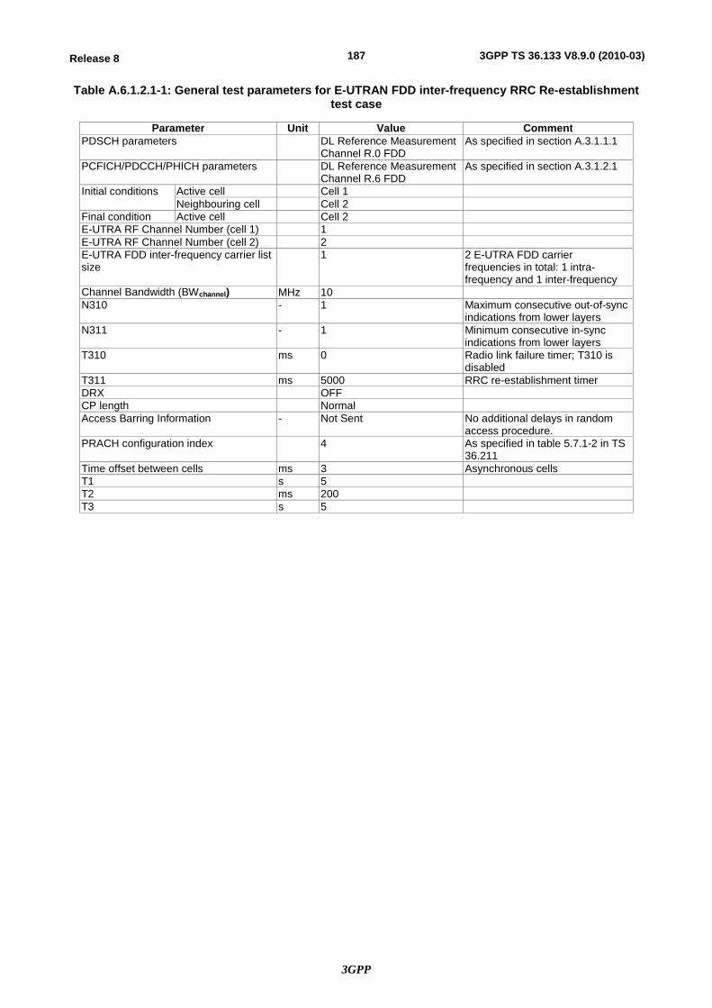
3GPP
187Release 8 3GPP TS 36.133 V8.9.0 (2010-03)
Table A.6.1.2.1-1: General test parameters for E-UTRAN FDD inter-frequency RRC Re-establishment test case
Parameter Unit Value Comment PDSCH parameters DL Reference Measurement
Channel R.0 FDD As specified in section A.3.1.1.1
PCFICH/PDCCH/PHICH parameters DL Reference Measurement Channel R.6 FDD
As specified in section A.3.1.2.1
Initial conditions Active cell Cell 1 Neighbouring cell Cell 2
Final condition Active cell Cell 2 E-UTRA RF Channel Number (cell 1) 1 E-UTRA RF Channel Number (cell 2) 2 E-UTRA FDD inter-frequency carrier list size
1 2 E-UTRA FDD carrier frequencies in total: 1 intra-frequency and 1 inter-frequency
Channel Bandwidth (BWchannel) MHz 10 N310 - 1 Maximum consecutive out-of-sync
indications from lower layers N311 - 1 Minimum consecutive in-sync
indications from lower layers T310 ms 0 Radio link failure timer; T310 is
disabled T311 ms 5000 RRC re-establishment timer DRX OFF CP length Normal Access Barring Information - Not Sent No additional delays in random
access procedure. PRACH configuration index 4 As specified in table 5.7.1-2 in TS
36.211 Time offset between cells ms 3 Asynchronous cells T1 s 5 T2 ms 200 T3 s 5
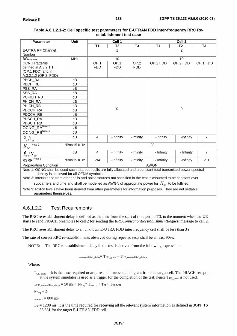
3GPP
188Release 8 3GPP TS 36.133 V8.9.0 (2010-03)
Table A.6.1.2.1-2: Cell specific test parameters for E-UTRAN FDD inter-frequency RRC Re-establishment test case
Parameter Unit Cell 1 Cell 2 T1 T2 T3 T1 T2 T3
E-UTRA RF Channel Number
1 2
BWchannel MHz 10 10 OCNG Patterns defined in A.3.2.1.1 (OP.1 FDD) and in A.3.2.1.2 (OP.2 FDD)
OP.1 FDD
OP.1 FDD
OP.2 FDD
OP.2 FDD OP.2 FDD OP.1 FDD
PBCH_RA dB
0
0
PBCH_RB dB PSS_RA dB SSS_RA dB PCFICH_RB dB PHICH_RA dB PHICH_RB dB PDCCH_RA dB PDCCH_RB dB PDSCH_RA dB PDSCH_RB dB OCNG_RANote 1 dB OCNG_RBNote 1 dB
ots IÊ dB 4 -Infinity -Infinity -Infinity -Infinity 7
ocN Note 2 dBm/15 KHz -98
ocs NÊ dB 4 -Infinity -Infinity - Infinity - Infinity 7
RSRP Note 3 dBm/15 KHz -94 -Infinity -Infinity - Infinity -Infinity -91 Propagation Condition AWGN Note 1: OCNG shall be used such that both cells are fully allocated and a constant total transmitted power spectral
density is achieved for all OFDM symbols. Note 2: Interference from other cells and noise sources not specified in the test is assumed to be constant over
subcarriers and time and shall be modelled as AWGN of appropriate power for ocN to be fulfilled. Note 3: RSRP levels have been derived from other parameters for information purposes. They are not settable
parameters themselves.
A.6.1.2.2 Test Requirements
The RRC re-establishment delay is defined as the time from the start of time period T3, to the moment when the UE starts to send PRACH preambles to cell 2 for sending the RRCConnectionReestablishmentRequest message to cell 2.
The RRC re-establishment delay to an unknown E-UTRA FDD inter frequency cell shall be less than 3 s.
The rate of correct RRC re-establishments observed during repeated tests shall be at least 90%.
NOTE: The RRC re-establishment delay in the test is derived from the following expression:
Tre-establish_delay= TUL_grant + TUE_re-establish_delay.
Where:
TUL_grant = It is the time required to acquire and process uplink grant from the target cell. The PRACH reception at the system simulator is used as a trigger for the completion of the test; hence TUL_grant is not used.
TUE_re-establish_delay = 50 ms + Nfreq* Tsearch + TSI + TPRACH
Nfreq = 2
Tsearch = 800 ms
TSI = 1280 ms; it is the time required for receiving all the relevant system information as defined in 3GPP TS 36.331 for the target E-UTRAN FDD cell.
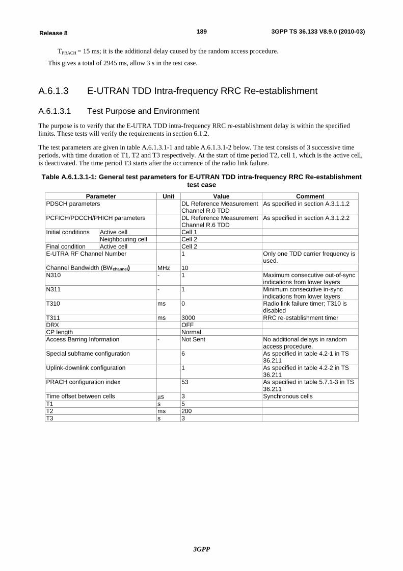
3GPP
189Release 8 3GPP TS 36.133 V8.9.0 (2010-03)
TPRACH = 15 ms; it is the additional delay caused by the random access procedure.
This gives a total of 2945 ms, allow 3 s in the test case.
A.6.1.3 E-UTRAN TDD Intra-frequency RRC Re-establishment
A.6.1.3.1 Test Purpose and Environment
The purpose is to verify that the E-UTRA TDD intra-frequency RRC re-establishment delay is within the specified limits. These tests will verify the requirements in section 6.1.2.
The test parameters are given in table A.6.1.3.1-1 and table A.6.1.3.1-2 below. The test consists of 3 successive time periods, with time duration of T1, T2 and T3 respectively. At the start of time period T2, cell 1, which is the active cell, is deactivated. The time period T3 starts after the occurrence of the radio link failure.
Table A.6.1.3.1-1: General test parameters for E-UTRAN TDD intra-frequency RRC Re-establishment test case
Parameter Unit Value Comment PDSCH parameters DL Reference Measurement
Channel R.0 TDD As specified in section A.3.1.1.2
PCFICH/PDCCH/PHICH parameters DL Reference Measurement Channel R.6 TDD
As specified in section A.3.1.2.2
Initial conditions Active cell Cell 1 Neighbouring cell Cell 2
Final condition Active cell Cell 2 E-UTRA RF Channel Number 1 Only one TDD carrier frequency is
used. Channel Bandwidth (BWchannel) MHz 10 N310 - 1 Maximum consecutive out-of-sync
indications from lower layers N311 - 1 Minimum consecutive in-sync
indications from lower layers T310 ms 0 Radio link failure timer; T310 is
disabled T311 ms 3000 RRC re-establishment timer DRX OFF CP length Normal Access Barring Information - Not Sent No additional delays in random
access procedure. Special subframe configuration 6 As specified in table 4.2-1 in TS
36.211 Uplink-downlink configuration 1 As specified in table 4.2-2 in TS
36.211 PRACH configuration index 53 As specified in table 5.7.1-3 in TS
36.211 Time offset between cells ms 3 Synchronous cells T1 s 5 T2 ms 200 T3 s 3
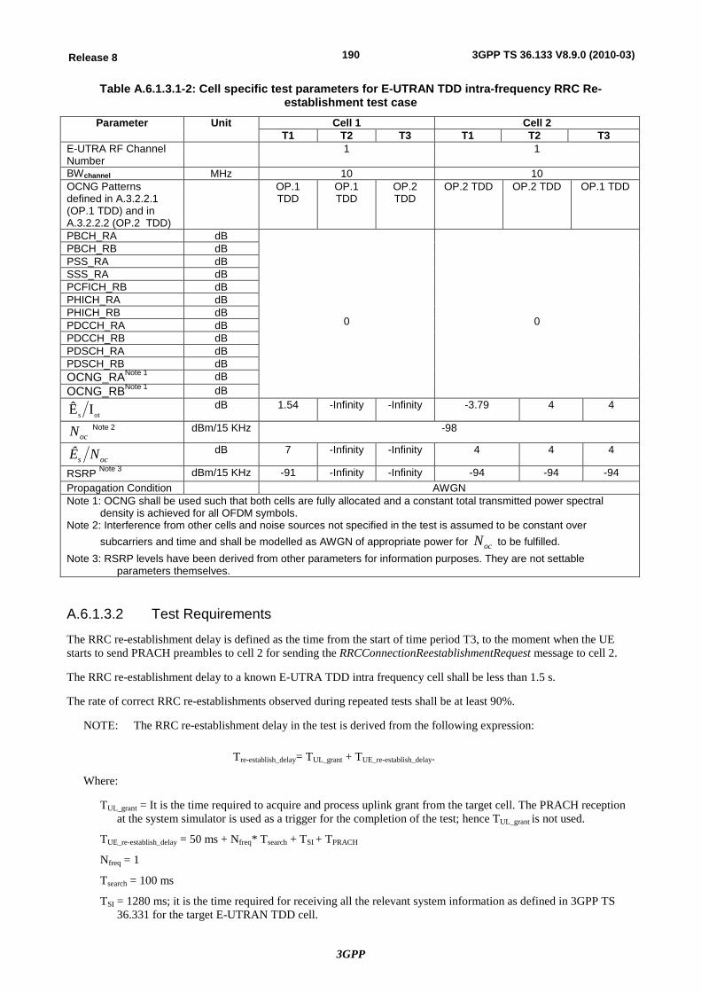
3GPP
190Release 8 3GPP TS 36.133 V8.9.0 (2010-03)
Table A.6.1.3.1-2: Cell specific test parameters for E-UTRAN TDD intra-frequency RRC Re-establishment test case
Parameter Unit Cell 1 Cell 2 T1 T2 T3 T1 T2 T3
E-UTRA RF Channel Number
1 1
BWchannel MHz 10 10 OCNG Patterns defined in A.3.2.2.1 (OP.1 TDD) and in A.3.2.2.2 (OP.2 TDD)
OP.1 TDD
OP.1 TDD
OP.2 TDD
OP.2 TDD OP.2 TDD OP.1 TDD
PBCH_RA dB
0
0
PBCH_RB dB PSS_RA dB SSS_RA dB PCFICH_RB dB PHICH_RA dB PHICH_RB dB PDCCH_RA dB PDCCH_RB dB PDSCH_RA dB PDSCH_RB dB OCNG_RANote 1 dB OCNG_RBNote 1 dB
ots IÊ dB 1.54 -Infinity -Infinity -3.79 4 4
ocN Note 2 dBm/15 KHz -98
ocs NÊ dB 7 -Infinity -Infinity 4 4 4
RSRP Note 3 dBm/15 KHz -91 -Infinity -Infinity -94 -94 -94 Propagation Condition AWGN Note 1: OCNG shall be used such that both cells are fully allocated and a constant total transmitted power spectral
density is achieved for all OFDM symbols. Note 2: Interference from other cells and noise sources not specified in the test is assumed to be constant over
subcarriers and time and shall be modelled as AWGN of appropriate power for ocN to be fulfilled. Note 3: RSRP levels have been derived from other parameters for information purposes. They are not settable
parameters themselves.
A.6.1.3.2 Test Requirements
The RRC re-establishment delay is defined as the time from the start of time period T3, to the moment when the UE starts to send PRACH preambles to cell 2 for sending the RRCConnectionReestablishmentRequest message to cell 2.
The RRC re-establishment delay to a known E-UTRA TDD intra frequency cell shall be less than 1.5 s.
The rate of correct RRC re-establishments observed during repeated tests shall be at least 90%.
NOTE: The RRC re-establishment delay in the test is derived from the following expression:
Tre-establish_delay= TUL_grant + TUE_re-establish_delay.
Where:
TUL_grant = It is the time required to acquire and process uplink grant from the target cell. The PRACH reception at the system simulator is used as a trigger for the completion of the test; hence TUL_grant is not used.
TUE_re-establish_delay = 50 ms + Nfreq* Tsearch + TSI + TPRACH
Nfreq = 1
Tsearch = 100 ms
TSI = 1280 ms; it is the time required for receiving all the relevant system information as defined in 3GPP TS 36.331 for the target E-UTRAN TDD cell.
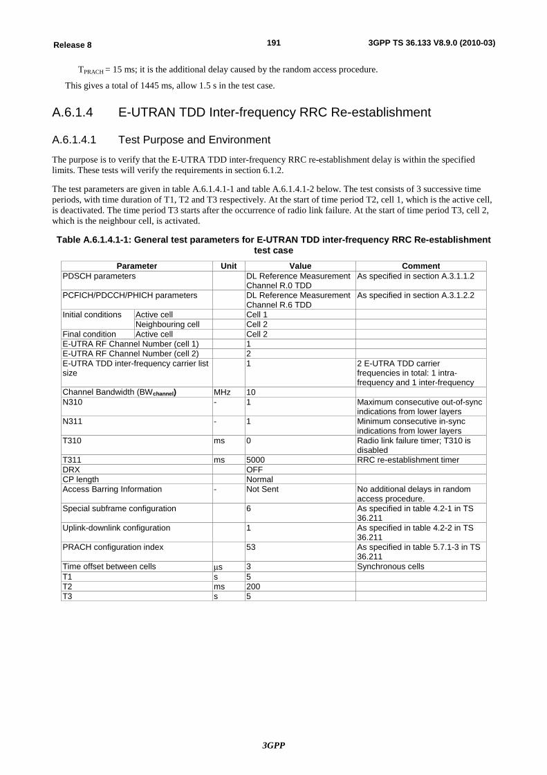
3GPP
191Release 8 3GPP TS 36.133 V8.9.0 (2010-03)
TPRACH = 15 ms; it is the additional delay caused by the random access procedure.
This gives a total of 1445 ms, allow 1.5 s in the test case.
A.6.1.4 E-UTRAN TDD Inter-frequency RRC Re-establishment
A.6.1.4.1 Test Purpose and Environment
The purpose is to verify that the E-UTRA TDD inter-frequency RRC re-establishment delay is within the specified limits. These tests will verify the requirements in section 6.1.2.
The test parameters are given in table A.6.1.4.1-1 and table A.6.1.4.1-2 below. The test consists of 3 successive time periods, with time duration of T1, T2 and T3 respectively. At the start of time period T2, cell 1, which is the active cell, is deactivated. The time period T3 starts after the occurrence of radio link failure. At the start of time period T3, cell 2, which is the neighbour cell, is activated.
Table A.6.1.4.1-1: General test parameters for E-UTRAN TDD inter-frequency RRC Re-establishment test case
Parameter Unit Value Comment PDSCH parameters DL Reference Measurement
Channel R.0 TDD As specified in section A.3.1.1.2
PCFICH/PDCCH/PHICH parameters DL Reference Measurement Channel R.6 TDD
As specified in section A.3.1.2.2
Initial conditions Active cell Cell 1 Neighbouring cell Cell 2
Final condition Active cell Cell 2 E-UTRA RF Channel Number (cell 1) 1 E-UTRA RF Channel Number (cell 2) 2 E-UTRA TDD inter-frequency carrier list size
1 2 E-UTRA TDD carrier frequencies in total: 1 intra-frequency and 1 inter-frequency
Channel Bandwidth (BWchannel) MHz 10 N310 - 1 Maximum consecutive out-of-sync
indications from lower layers N311 - 1 Minimum consecutive in-sync
indications from lower layers T310 ms 0 Radio link failure timer; T310 is
disabled T311 ms 5000 RRC re-establishment timer DRX OFF CP length Normal Access Barring Information - Not Sent No additional delays in random
access procedure. Special subframe configuration 6 As specified in table 4.2-1 in TS
36.211 Uplink-downlink configuration 1 As specified in table 4.2-2 in TS
36.211 PRACH configuration index 53 As specified in table 5.7.1-3 in TS
36.211 Time offset between cells ms 3 Synchronous cells T1 s 5 T2 ms 200 T3 s 5
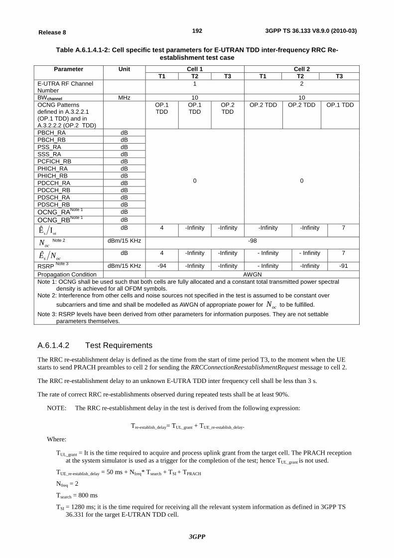
3GPP
192Release 8 3GPP TS 36.133 V8.9.0 (2010-03)
Table A.6.1.4.1-2: Cell specific test parameters for E-UTRAN TDD inter-frequency RRC Re-establishment test case
Parameter Unit Cell 1 Cell 2 T1 T2 T3 T1 T2 T3
E-UTRA RF Channel Number
1 2
BWchannel MHz 10 10 OCNG Patterns defined in A.3.2.2.1 (OP.1 TDD) and in A.3.2.2.2 (OP.2 TDD)
OP.1 TDD
OP.1 TDD
OP.2 TDD
OP.2 TDD OP.2 TDD OP.1 TDD
PBCH_RA dB
0
0
PBCH_RB dB PSS_RA dB SSS_RA dB PCFICH_RB dB PHICH_RA dB PHICH_RB dB PDCCH_RA dB PDCCH_RB dB PDSCH_RA dB PDSCH_RB dB OCNG_RANote 1 dB OCNG_RBNote 1 dB
ots IÊ dB 4 -Infinity -Infinity -Infinity -Infinity 7
ocN Note 2 dBm/15 KHz -98
ocs NÊ dB 4 -Infinity -Infinity - Infinity - Infinity 7
RSRP Note 3 dBm/15 KHz -94 -Infinity -Infinity - Infinity -Infinity -91 Propagation Condition AWGN Note 1: OCNG shall be used such that both cells are fully allocated and a constant total transmitted power spectral
density is achieved for all OFDM symbols. Note 2: Interference from other cells and noise sources not specified in the test is assumed to be constant over
subcarriers and time and shall be modelled as AWGN of appropriate power for ocN to be fulfilled. Note 3: RSRP levels have been derived from other parameters for information purposes. They are not settable
parameters themselves.
A.6.1.4.2 Test Requirements
The RRC re-establishment delay is defined as the time from the start of time period T3, to the moment when the UE starts to send PRACH preambles to cell 2 for sending the RRCConnectionReestablishmentRequest message to cell 2.
The RRC re-establishment delay to an unknown E-UTRA TDD inter frequency cell shall be less than 3 s.
The rate of correct RRC re-establishments observed during repeated tests shall be at least 90%.
NOTE: The RRC re-establishment delay in the test is derived from the following expression:
Tre-establish_delay= TUL_grant + TUE_re-establish_delay.
Where:
TUL_grant = It is the time required to acquire and process uplink grant from the target cell. The PRACH reception at the system simulator is used as a trigger for the completion of the test; hence TUL_grant is not used.
TUE_re-establish_delay = 50 ms + Nfreq* Tsearch + TSI + TPRACH
Nfreq = 2
Tsearch = 800 ms
TSI = 1280 ms; it is the time required for receiving all the relevant system information as defined in 3GPP TS 36.331 for the target E-UTRAN TDD cell.
3GPP
193Release 8 3GPP TS 36.133 V8.9.0 (2010-03)
TPRACH = 15 ms; it is the additional delay caused by the random access procedure.
This gives a total of 2945 ms, allow 3 s in the test case.
A.6.2 Random Access
A.6.2.1 E-UTRAN FDD – Contention Based Random Access Test
A.6.2.1.1 Test Purpose and Environment
The purpose of this test is to verify that the behavior of the random access procedure is according to the requirements and that the PRACH power settings and timing are within specified limits. This test will verify the requirements in Section 6.2.2 and Section 7.1.2 in an AWGN model.
For this test a single cell is used. The test parameters are given in tables A.6.2.1.1-1 and A.6.2.1.1-2.
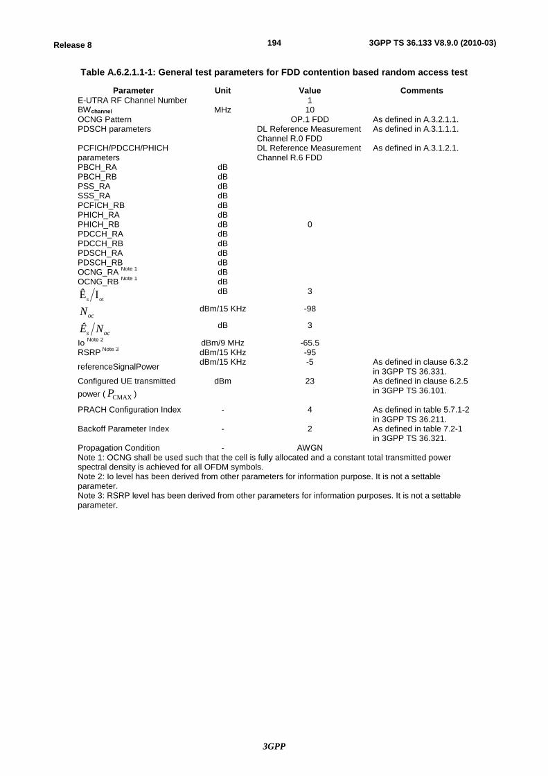
3GPP
194Release 8 3GPP TS 36.133 V8.9.0 (2010-03)
Table A.6.2.1.1-1: General test parameters for FDD contention based random access test
Parameter Unit Value Comments E-UTRA RF Channel Number 1 BWchannel MHz 10 OCNG Pattern OP.1 FDD As defined in A.3.2.1.1. PDSCH parameters DL Reference Measurement
Channel R.0 FDD As defined in A.3.1.1.1.
PCFICH/PDCCH/PHICH parameters
DL Reference Measurement Channel R.6 FDD
As defined in A.3.1.2.1.
PBCH_RA dB
0
PBCH_RB dB PSS_RA dB SSS_RA dB PCFICH_RB dB PHICH_RA dB PHICH_RB dB PDCCH_RA dB PDCCH_RB dB PDSCH_RA dB PDSCH_RB dB OCNG_RA Note 1 dB OCNG_RB Note 1 dB
ots IÊ dB 3
ocN dBm/15 KHz -98
ocs NÊ dB 3
Io Note 2 dBm/9 MHz -65.5 RSRP Note 3 dBm/15 KHz -95
referenceSignalPower dBm/15 KHz -5 As defined in clause 6.3.2 in 3GPP TS 36.331.
Configured UE transmitted power ( CMAXP )
dBm 23 As defined in clause 6.2.5 in 3GPP TS 36.101.
PRACH Configuration Index - 4 As defined in table 5.7.1-2 in 3GPP TS 36.211.
Backoff Parameter Index - 2 As defined in table 7.2-1 in 3GPP TS 36.321.
Propagation Condition - AWGN Note 1: OCNG shall be used such that the cell is fully allocated and a constant total transmitted power spectral density is achieved for all OFDM symbols. Note 2: Io level has been derived from other parameters for information purpose. It is not a settable parameter. Note 3: RSRP level has been derived from other parameters for information purposes. It is not a settable parameter.
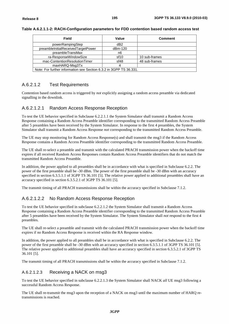
3GPP
195Release 8 3GPP TS 36.133 V8.9.0 (2010-03)
Table A.6.2.1.1-2: RACH-Configuration parameters for FDD contention based random access test
Field Value Comment powerRampingStep dB2
preambleInitialReceivedTargetPower dBm-120 preambleTransMax n6
ra-ResponseWindowSize sf10 10 sub-frames mac-ContentionResolutionTimer sf48 48 sub-frames
maxHARQ-Msg3Tx 4 Note: For further information see Section 6.3.2 in 3GPP TS 36.331.
A.6.2.1.2 Test Requirements
Contention based random access is triggered by not explicitly assigning a random access preamble via dedicated signalling in the downlink.
A.6.2.1.2.1 Random Access Response Reception
To test the UE behavior specified in Subclause 6.2.2.1.1 the System Simulator shall transmit a Random Access Response containing a Random Access Preamble identifier corresponding to the transmitted Random Access Preamble after 5 preambles have been received by the System Simulator. In response to the first 4 preambles, the System Simulator shall transmit a Random Access Response not corresponding to the transmitted Random Access Preamble.
The UE may stop monitoring for Random Access Response(s) and shall transmit the msg3 if the Random Access Response contains a Random Access Preamble identifier corresponding to the transmitted Random Access Preamble.
The UE shall re-select a preamble and transmit with the calculated PRACH transmission power when the backoff time expires if all received Random Access Responses contain Random Access Preamble identifiers that do not match the transmitted Random Access Preamble.
In addition, the power applied to all preambles shall be in accordance with what is specified in Subclause 6.2.2. The power of the first preamble shall be -30 dBm. The power of the first preamble shall be -30 dBm with an accuracy specified in section 6.3.5.1.1 of 3GPP TS 36.101 [5]. The relative power applied to additional preambles shall have an accuracy specified in section 6.3.5.2.1 of 3GPP TS 36.101 [5].
The transmit timing of all PRACH transmissions shall be within the accuracy specified in Subclause 7.1.2.
A.6.2.1.2.2 No Random Access Response Reception
To test the UE behavior specified in subclause 6.2.2.1.2 the System Simulator shall transmit a Random Access Response containing a Random Access Preamble identifier corresponding to the transmitted Random Access Preamble after 5 preambles have been received by the System Simulator. The System Simulator shall not respond to the first 4 preambles.
The UE shall re-select a preamble and transmit with the calculated PRACH transmission power when the backoff time expires if no Random Access Response is received within the RA Response window.
In addition, the power applied to all preambles shall be in accordance with what is specified in Subclause 6.2.2. The power of the first preamble shall be -30 dBm with an accuracy specified in section 6.3.5.1.1 of 3GPP TS 36.101 [5]. The relative power applied to additional preambles shall have an accuracy specified in section 6.3.5.2.1 of 3GPP TS 36.101 [5].
The transmit timing of all PRACH transmissions shall be within the accuracy specified in Subclause 7.1.2.
A.6.2.1.2.3 Receiving a NACK on msg3
To test the UE behavior specified in subclause 6.2.2.1.3 the System Simulator shall NACK all UE msg3 following a successful Random Access Response.
The UE shall re-transmit the msg3 upon the reception of a NACK on msg3 until the maximum number of HARQ re-transmissions is reached.
3GPP
196Release 8 3GPP TS 36.133 V8.9.0 (2010-03)
A.6.2.1.2.4 Reception of an Incorrect Message over Temporary C-RNTI
To test the UE behavior specified in Subclause 6.2.2.1.5 the System Simulator shall send a message addressed to the temporary C-RNTI with a UE Contention Resolution Identity included in the MAC control element not matching the CCCH SDU transmitted in msg3 uplink message.
The UE shall re-select a preamble and transmit with the calculated PRACH transmission power when the backoff time expires unless the received message includes a UE Contention Resolution Identity MAC control element and the UE Contention Resolution Identity included in the MAC control element matches the CCCH SDU transmitted in the uplink message.
A.6.2.1.2.5 Reception of a Correct Message over Temporary C-RNTI
To test the UE behavior specified in Subclause 6.2.2.1.5 the System Simulator shall send a message addressed to the temporary C-RNTI with a UE Contention Resolution Identity included in the MAC control element matching the CCCH SDU transmitted in the msg3 uplink message.
The UE shall send ACK if the Contention Resolution is successful.
A.6.2.1.2.6 Contention Resolution Timer expiry
To test the UE behavior specified in Subclause 6.2.2.1.6 the System Simulator shall not send a response to a msg3.
The UE shall re-select a preamble and transmit with the calculated PRACH transmission power when the backoff time expires if the Contention Resolution Timer expires.
A.6.2.2 E-UTRAN FDD – Non-Contention Based Random Access Test
A.6.2.2.1 Test Purpose and Environment
The purpose of this test is to verify that the behavior of the random access procedure is according to the requirements and that the PRACH power settings and timing are within specified limits. This test will verify the requirements in Section 6.2.2 and Section 7.1.2 in an AWGN model.
For this test a single cell is used. The test parameters are given in tables A.6.2.2.1-1 and A.6.2.2.1-2.
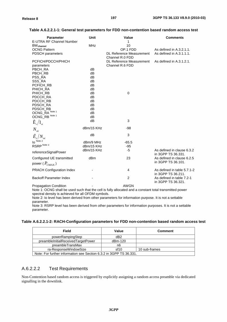
3GPP
197Release 8 3GPP TS 36.133 V8.9.0 (2010-03)
Table A.6.2.2.1-1: General test parameters for FDD non-contention based random access test
Parameter Unit Value Comments E-UTRA RF Channel Number 1 BWchannel MHz 10 OCNG Pattern OP.1 FDD As defined in A.3.2.1.1. PDSCH parameters DL Reference Measurement
Channel R.0 FDD As defined in A.3.1.1.1.
PCFICH/PDCCH/PHICH parameters
DL Reference Measurement Channel R.6 FDD
As defined in A.3.1.2.1.
PBCH_RA dB
0
PBCH_RB dB PSS_RA dB SSS_RA dB PCFICH_RB dB PHICH_RA dB PHICH_RB dB PDCCH_RA dB PDCCH_RB dB PDSCH_RA dB PDSCH_RB dB OCNG_RA Note 1 dB OCNG_RB Note 1 dB
ots IÊ dB 3
ocN dBm/15 KHz -98
ocs NÊ dB 3
Io Note 2 dBm/9 MHz -65.5 RSRP Note 3 dBm/15 KHz -95
referenceSignalPower dBm/15 KHz -5 As defined in clause 6.3.2 in 3GPP TS 36.331.
Configured UE transmitted power ( CMAXP )
dBm 23 As defined in clause 6.2.5 in 3GPP TS 36.101.
PRACH Configuration Index - 4 As defined in table 5.7.1-2 in 3GPP TS 36.211.
Backoff Parameter Index - 2 As defined in table 7.2-1 in 3GPP TS 36.321.
Propagation Condition - AWGN Note 1: OCNG shall be used such that the cell is fully allocated and a constant total transmitted power spectral density is achieved for all OFDM symbols. Note 2: Io level has been derived from other parameters for information purpose. It is not a settable parameter. Note 3: RSRP level has been derived from other parameters for information purposes. It is not a settable parameter.
Table A.6.2.2.1-2: RACH-Configuration parameters for FDD non-contention based random access test
Field Value Comment powerRampingStep dB2
preambleInitialReceivedTargetPower dBm-120 preambleTransMax n6
ra-ResponseWindowSize sf10 10 sub-frames Note: For further information see Section 6.3.2 in 3GPP TS 36.331.
A.6.2.2.2 Test Requirements
Non-Contention based random access is triggered by explicitly assigning a random access preamble via dedicated signalling in the downlink.
3GPP
198Release 8 3GPP TS 36.133 V8.9.0 (2010-03)
A.6.2.2.2.1 Random Access Response Reception
To test the UE behavior specified in Subclause 6.2.2.2.1 the System Simulator shall transmit a Random Access Response containing a Random Access Preamble identifier corresponding to the transmitted Random Access Preamble after 5 preambles have been received by the System Simulator. In response to the first 4 preambles, the System Simulator shall transmit a Random Access Response not corresponding to the transmitted Random Access Preamble.
The UE may stop monitoring for Random Access Response(s) if the Random Access Response contains a Random Access Preamble identifier corresponding to the transmitted Random Access Preamble.
The UE shall re-transmit the preamble with the calculated PRACH transmission power if all received Random Access Responses contain Random Access Preamble identifiers that do not match the transmitted Random Access Preamble.
In addition, the power applied to all preambles shall be in accordance with what is specified in Subclause 6.2.2. The power of the first preamble shall be -30 dBm with an accuracy specified in section 6.3.5.1.1 of 3GPP TS 36.101 [5]. The relative power applied to additional preambles shall have an accuracy specified in section 6.3.5.2.1 of 3GPP TS 36.101 [5].
The transmit timing of all PRACH transmissions shall be within the accuracy specified in Subclause 7.1.2.
A.6.2.2.2.2 No Random Access Response Reception
To test the UE behavior specified in subclause 6.2.2.2.2 the System Simulator shall transmit a Random Access Response containing a Random Access Preamble identifier corresponding to the transmitted Random Access Preamble after 5 preambles have been received by the System Simulator. The System Simulator shall not respond to the first 4 preambles.
The UE shall re-transmit the preamble with the calculated PRACH transmission power.
In addition, the power applied to all preambles shall be in accordance with what is specified in Subclause 6.2.2. The power of the first preamble shall be -30 dBm with an accuracy specified in section 6.3.5.1.1 of 3GPP TS 36.101 [5]. The relative power applied to additional preambles shall have an accuracy specified in section 6.3.5.2.1 of 3GPP TS 36.101 [5].
The transmit timing of all PRACH transmissions shall be within the accuracy specified in Subclause 7.1.2.
A.6.2.3 E-UTRAN TDD – Contention Based Random Access Test
A.6.2.3.1 Test Purpose and Environment
The purpose of this test is to verify that the behavior of the random access procedure is according to the requirements and that the PRACH power settings and timing are within specified limits. This test will verify the requirements in Section 6.2.2 and Section 7.1.2 in an AWGN model.
For this test a single cell is used. The test parameters are given in tables A.6.2.3.1-1 and A.6.2.3.1-2.
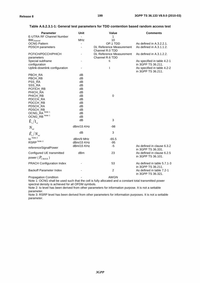
3GPP
199Release 8 3GPP TS 36.133 V8.9.0 (2010-03)
Table A.6.2.3.1-1: General test parameters for TDD contention based random access test
Parameter Unit Value Comments E-UTRA RF Channel Number - 1 BWchannel MHz 10 OCNG Pattern - OP.1 TDD As defined in A.3.2.2.1. PDSCH parameters - DL Reference Measurement
Channel R.0 TDD As defined in A.3.1.1.2.
PCFICH/PDCCH/PHICH parameters
- DL Reference Measurement Channel R.6 TDD
As defined in A.3.1.2.2.
Special subframe configuration
- 6 As specified in table 4.2-1 in 3GPP TS 36.211.
Uplink-downlink configuration - 1 As specified in table 4.2-2 in 3GPP TS 36.211.
PBCH_RA dB
0
PBCH_RB dB PSS_RA dB SSS_RA dB PCFICH_RB dB PHICH_RA dB PHICH_RB dB PDCCH_RA dB PDCCH_RB dB PDSCH_RA dB PDSCH_RB dB OCNG_RA Note 1 dB OCNG_RB Note 1 dB
ots IÊ dB 3
ocN dBm/15 KHz -98
ocs NÊ dB 3
Io Note 2 dBm/9 MHz -65.5 RSRP Note 3 dBm/15 KHz -95
referenceSignalPower dBm/15 KHz -5 As defined in clause 6.3.2 in 3GPP TS 36.331.
Configured UE transmitted power ( CMAXP )
dBm 23 As defined in clause 6.2.5 in 3GPP TS 36.101.
PRACH Configuration Index - 53 As defined in table 5.7.1-3 in 3GPP TS 36.211.
Backoff Parameter Index - 2 As defined in table 7.2-1 in 3GPP TS 36.321.
Propagation Condition - AWGN Note 1: OCNG shall be used such that the cell is fully allocated and a constant total transmitted power spectral density is achieved for all OFDM symbols. Note 2: Io level has been derived from other parameters for information purpose. It is not a settable parameter. Note 3: RSRP level has been derived from other parameters for information purposes. It is not a settable parameter.
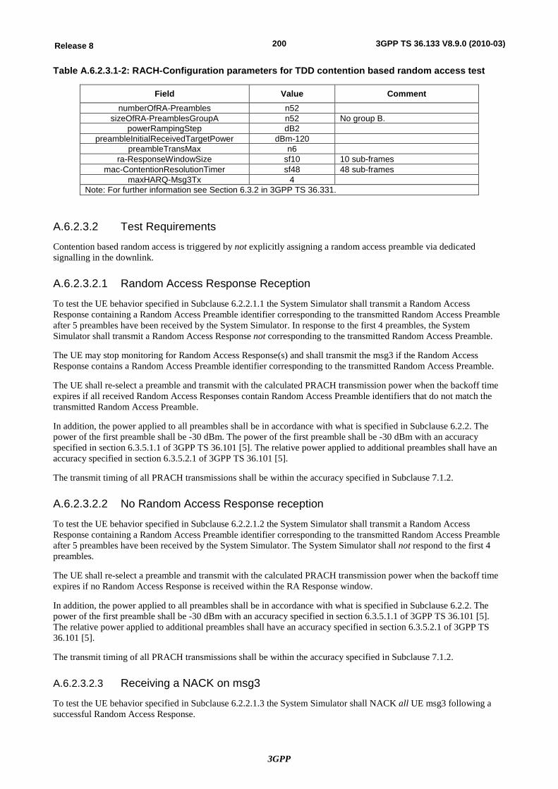
3GPP
200Release 8 3GPP TS 36.133 V8.9.0 (2010-03)
Table A.6.2.3.1-2: RACH-Configuration parameters for TDD contention based random access test
Field Value Comment numberOfRA-Preambles n52
sizeOfRA-PreamblesGroupA n52 No group B. powerRampingStep dB2
preambleInitialReceivedTargetPower dBm-120 preambleTransMax n6
ra-ResponseWindowSize sf10 10 sub-frames mac-ContentionResolutionTimer sf48 48 sub-frames
maxHARQ-Msg3Tx 4 Note: For further information see Section 6.3.2 in 3GPP TS 36.331.
A.6.2.3.2 Test Requirements
Contention based random access is triggered by not explicitly assigning a random access preamble via dedicated signalling in the downlink.
A.6.2.3.2.1 Random Access Response Reception
To test the UE behavior specified in Subclause 6.2.2.1.1 the System Simulator shall transmit a Random Access Response containing a Random Access Preamble identifier corresponding to the transmitted Random Access Preamble after 5 preambles have been received by the System Simulator. In response to the first 4 preambles, the System Simulator shall transmit a Random Access Response not corresponding to the transmitted Random Access Preamble.
The UE may stop monitoring for Random Access Response(s) and shall transmit the msg3 if the Random Access Response contains a Random Access Preamble identifier corresponding to the transmitted Random Access Preamble.
The UE shall re-select a preamble and transmit with the calculated PRACH transmission power when the backoff time expires if all received Random Access Responses contain Random Access Preamble identifiers that do not match the transmitted Random Access Preamble.
In addition, the power applied to all preambles shall be in accordance with what is specified in Subclause 6.2.2. The power of the first preamble shall be -30 dBm. The power of the first preamble shall be -30 dBm with an accuracy specified in section 6.3.5.1.1 of 3GPP TS 36.101 [5]. The relative power applied to additional preambles shall have an accuracy specified in section 6.3.5.2.1 of 3GPP TS 36.101 [5].
The transmit timing of all PRACH transmissions shall be within the accuracy specified in Subclause 7.1.2.
A.6.2.3.2.2 No Random Access Response reception
To test the UE behavior specified in Subclause 6.2.2.1.2 the System Simulator shall transmit a Random Access Response containing a Random Access Preamble identifier corresponding to the transmitted Random Access Preamble after 5 preambles have been received by the System Simulator. The System Simulator shall not respond to the first 4 preambles.
The UE shall re-select a preamble and transmit with the calculated PRACH transmission power when the backoff time expires if no Random Access Response is received within the RA Response window.
In addition, the power applied to all preambles shall be in accordance with what is specified in Subclause 6.2.2. The power of the first preamble shall be -30 dBm with an accuracy specified in section 6.3.5.1.1 of 3GPP TS 36.101 [5]. The relative power applied to additional preambles shall have an accuracy specified in section 6.3.5.2.1 of 3GPP TS 36.101 [5].
The transmit timing of all PRACH transmissions shall be within the accuracy specified in Subclause 7.1.2.
A.6.2.3.2.3 Receiving a NACK on msg3
To test the UE behavior specified in Subclause 6.2.2.1.3 the System Simulator shall NACK all UE msg3 following a successful Random Access Response.
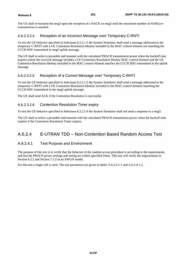
3GPP
201Release 8 3GPP TS 36.133 V8.9.0 (2010-03)
The UE shall re-transmit the msg3 upon the reception of a NACK on msg3 until the maximum number of HARQ re-transmissions is reached.
A.6.2.3.2.4 Reception of an Incorrect Message over Temporary C-RNTI
To test the UE behavior specified in Subclause 6.2.2.1.5 the System Simulator shall send a message addressed to the temporary C-RNTI with a UE Contention Resolution Identity included in the MAC control element not matching the CCCH SDU transmitted in msg3 uplink message.
The UE shall re-select a preamble and transmit with the calculated PRACH transmission power when the backoff time expires unless the received message includes a UE Contention Resolution Identity MAC control element and the UE Contention Resolution Identity included in the MAC control element matches the CCCH SDU transmitted in the uplink message.
A.6.2.3.2.5 Reception of a Correct Message over Temporary C-RNTI
To test the UE behavior specified in Subclause 6.2.2.1.5 the System Simulator shall send a message addressed to the temporary C-RNTI with a UE Contention Resolution Identity included in the MAC control element matching the CCCH SDU transmitted in the msg3 uplink message.
The UE shall send ACK if the Contention Resolution is successful.
A.6.2.3.2.6 Contention Resolution Timer expiry
To test the UE behavior specified in Subclause 6.2.2.1.6 the System Simulator shall not send a response to a msg3.
The UE shall re-select a preamble and transmit with the calculated PRACH transmission power when the backoff time expires if the Contention Resolution Timer expires.
A.6.2.4 E-UTRAN TDD – Non-Contention Based Random Access Test
A.6.2.4.1 Test Purpose and Environment
The purpose of this test is to verify that the behavior of the random access procedure is according to the requirements and that the PRACH power settings and timing are within specified limits. This test will verify the requirements in Section 6.2.2 and Section 7.1.2 in an AWGN model.
For this test a single cell is used. The test parameters are given in tables A.6.2.4.1-1 and A.6.2.4.1-2.
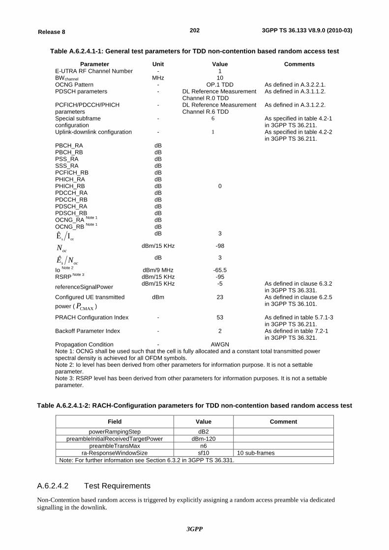
3GPP
202Release 8 3GPP TS 36.133 V8.9.0 (2010-03)
Table A.6.2.4.1-1: General test parameters for TDD non-contention based random access test
Parameter Unit Value Comments E-UTRA RF Channel Number - 1 BWchannel MHz 10 OCNG Pattern - OP.1 TDD As defined in A.3.2.2.1. PDSCH parameters - DL Reference Measurement
Channel R.0 TDD As defined in A.3.1.1.2.
PCFICH/PDCCH/PHICH parameters
- DL Reference Measurement Channel R.6 TDD
As defined in A.3.1.2.2.
Special subframe configuration
- 6 As specified in table 4.2-1 in 3GPP TS 36.211.
Uplink-downlink configuration - 1 As specified in table 4.2-2 in 3GPP TS 36.211.
PBCH_RA dB
0
PBCH_RB dB PSS_RA dB SSS_RA dB PCFICH_RB dB PHICH_RA dB PHICH_RB dB PDCCH_RA dB PDCCH_RB dB PDSCH_RA dB PDSCH_RB dB OCNG_RA Note 1 dB OCNG_RB Note 1 dB
ots IÊ dB 3
ocN dBm/15 KHz -98
ocs NÊ dB 3
Io Note 2 dBm/9 MHz -65.5 RSRP Note 3 dBm/15 KHz -95
referenceSignalPower dBm/15 KHz -5 As defined in clause 6.3.2 in 3GPP TS 36.331.
Configured UE transmitted power ( CMAXP )
dBm 23 As defined in clause 6.2.5 in 3GPP TS 36.101.
PRACH Configuration Index - 53 As defined in table 5.7.1-3 in 3GPP TS 36.211.
Backoff Parameter Index - 2 As defined in table 7.2-1 in 3GPP TS 36.321.
Propagation Condition - AWGN Note 1: OCNG shall be used such that the cell is fully allocated and a constant total transmitted power spectral density is achieved for all OFDM symbols. Note 2: Io level has been derived from other parameters for information purpose. It is not a settable parameter. Note 3: RSRP level has been derived from other parameters for information purposes. It is not a settable parameter.
Table A.6.2.4.1-2: RACH-Configuration parameters for TDD non-contention based random access test
Field Value Comment powerRampingStep dB2
preambleInitialReceivedTargetPower dBm-120 preambleTransMax n6
ra-ResponseWindowSize sf10 10 sub-frames Note: For further information see Section 6.3.2 in 3GPP TS 36.331.
A.6.2.4.2 Test Requirements
Non-Contention based random access is triggered by explicitly assigning a random access preamble via dedicated signalling in the downlink.
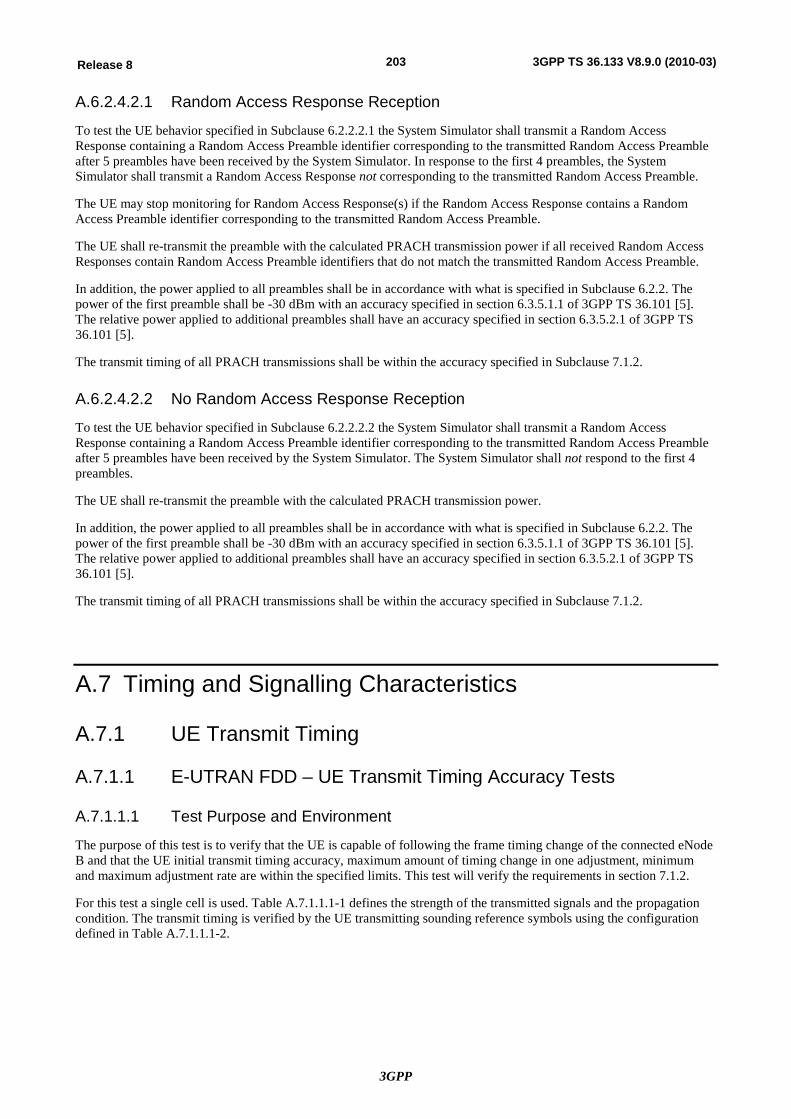
3GPP
203Release 8 3GPP TS 36.133 V8.9.0 (2010-03)
A.6.2.4.2.1 Random Access Response Reception
To test the UE behavior specified in Subclause 6.2.2.2.1 the System Simulator shall transmit a Random Access Response containing a Random Access Preamble identifier corresponding to the transmitted Random Access Preamble after 5 preambles have been received by the System Simulator. In response to the first 4 preambles, the System Simulator shall transmit a Random Access Response not corresponding to the transmitted Random Access Preamble.
The UE may stop monitoring for Random Access Response(s) if the Random Access Response contains a Random Access Preamble identifier corresponding to the transmitted Random Access Preamble.
The UE shall re-transmit the preamble with the calculated PRACH transmission power if all received Random Access Responses contain Random Access Preamble identifiers that do not match the transmitted Random Access Preamble.
In addition, the power applied to all preambles shall be in accordance with what is specified in Subclause 6.2.2. The power of the first preamble shall be -30 dBm with an accuracy specified in section 6.3.5.1.1 of 3GPP TS 36.101 [5]. The relative power applied to additional preambles shall have an accuracy specified in section 6.3.5.2.1 of 3GPP TS 36.101 [5].
The transmit timing of all PRACH transmissions shall be within the accuracy specified in Subclause 7.1.2.
A.6.2.4.2.2 No Random Access Response Reception
To test the UE behavior specified in Subclause 6.2.2.2.2 the System Simulator shall transmit a Random Access Response containing a Random Access Preamble identifier corresponding to the transmitted Random Access Preamble after 5 preambles have been received by the System Simulator. The System Simulator shall not respond to the first 4 preambles.
The UE shall re-transmit the preamble with the calculated PRACH transmission power.
In addition, the power applied to all preambles shall be in accordance with what is specified in Subclause 6.2.2. The power of the first preamble shall be -30 dBm with an accuracy specified in section 6.3.5.1.1 of 3GPP TS 36.101 [5]. The relative power applied to additional preambles shall have an accuracy specified in section 6.3.5.2.1 of 3GPP TS 36.101 [5].
The transmit timing of all PRACH transmissions shall be within the accuracy specified in Subclause 7.1.2.
A.7 Timing and Signalling Characteristics
A.7.1 UE Transmit Timing
A.7.1.1 E-UTRAN FDD – UE Transmit Timing Accuracy Tests
A.7.1.1.1 Test Purpose and Environment
The purpose of this test is to verify that the UE is capable of following the frame timing change of the connected eNode B and that the UE initial transmit timing accuracy, maximum amount of timing change in one adjustment, minimum and maximum adjustment rate are within the specified limits. This test will verify the requirements in section 7.1.2.
For this test a single cell is used. Table A.7.1.1.1-1 defines the strength of the transmitted signals and the propagation condition. The transmit timing is verified by the UE transmitting sounding reference symbols using the configuration defined in Table A.7.1.1.1-2.
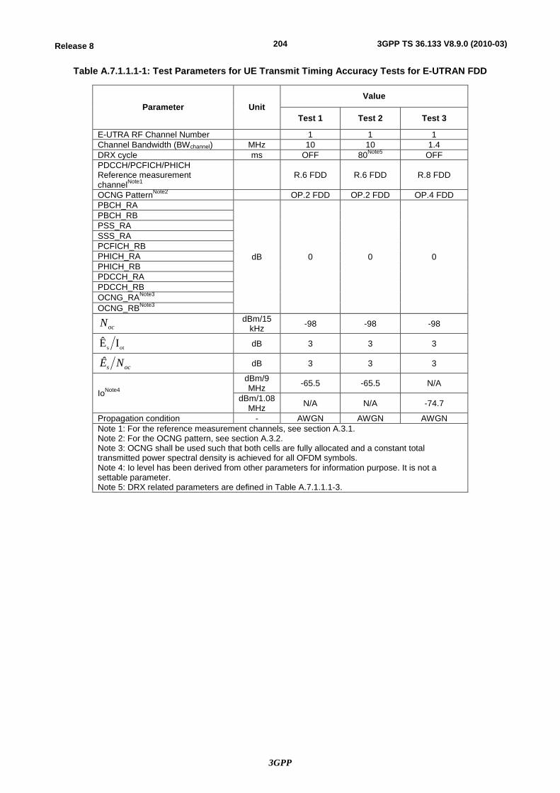
3GPP
204Release 8 3GPP TS 36.133 V8.9.0 (2010-03)
Table A.7.1.1.1-1: Test Parameters for UE Transmit Timing Accuracy Tests for E-UTRAN FDD
Parameter Unit Value
Test 1 Test 2 Test 3
E-UTRA RF Channel Number 1 1 1 Channel Bandwidth (BWchannel) MHz 10 10 1.4 DRX cycle ms OFF 80Note5 OFF PDCCH/PCFICH/PHICH Reference measurement channelNote1
R.6 FDD R.6 FDD R.8 FDD
OCNG PatternNote2 OP.2 FDD OP.2 FDD OP.4 FDD PBCH_RA
dB 0 0 0
PBCH_RB PSS_RA SSS_RA PCFICH_RB PHICH_RA PHICH_RB PDCCH_RA PDCCH_RB OCNG_RANote3 OCNG_RBNote3
ocN dBm/15 kHz -98 -98 -98
ots IÊ dB 3 3 3
ocs NÊ dB 3 3 3
IoNote4
dBm/9 MHz -65.5 -65.5 N/A
dBm/1.08 MHz N/A N/A -74.7
Propagation condition - AWGN AWGN AWGN Note 1: For the reference measurement channels, see section A.3.1. Note 2: For the OCNG pattern, see section A.3.2. Note 3: OCNG shall be used such that both cells are fully allocated and a constant total transmitted power spectral density is achieved for all OFDM symbols. Note 4: Io level has been derived from other parameters for information purpose. It is not a settable parameter. Note 5: DRX related parameters are defined in Table A.7.1.1.1-3.
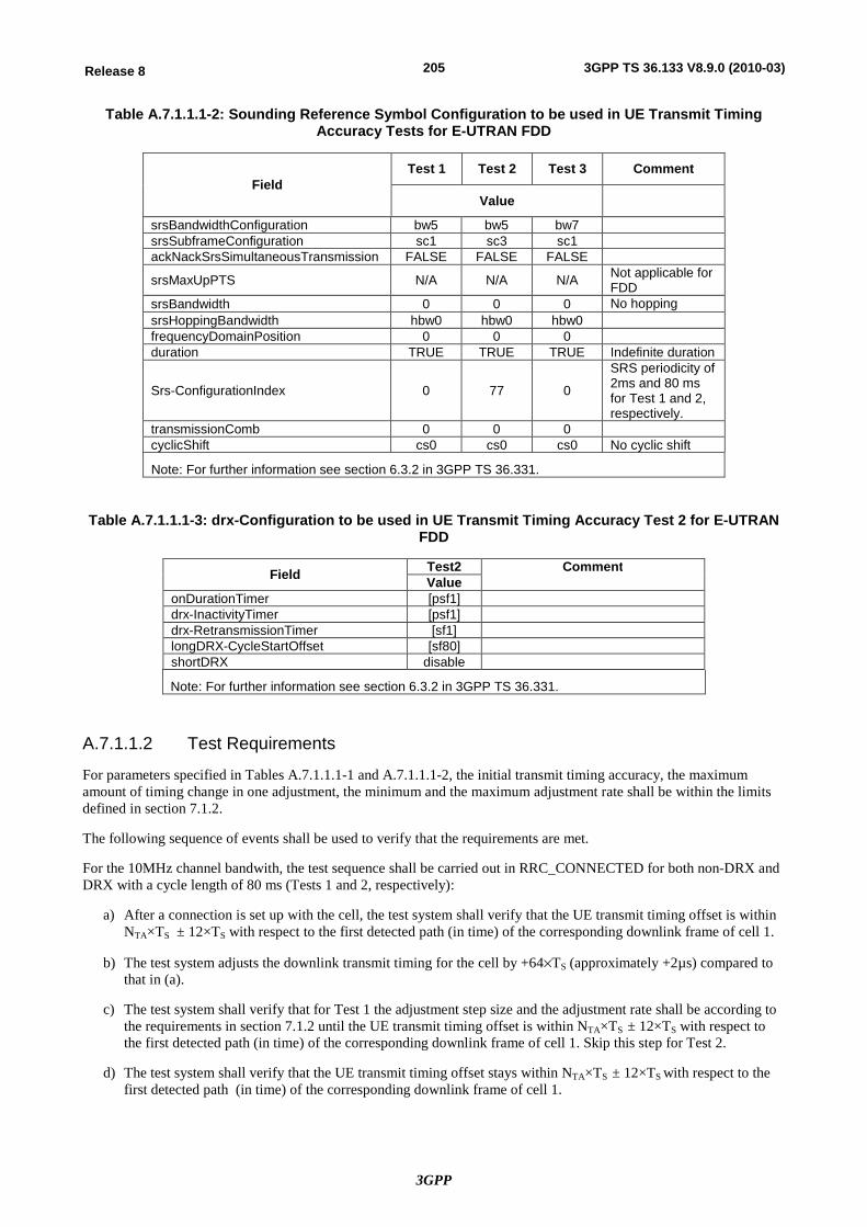
3GPP
205Release 8 3GPP TS 36.133 V8.9.0 (2010-03)
Table A.7.1.1.1-2: Sounding Reference Symbol Configuration to be used in UE Transmit Timing Accuracy Tests for E-UTRAN FDD
Field Test 1 Test 2 Test 3 Comment
Value
srsBandwidthConfiguration bw5 bw5 bw7 srsSubframeConfiguration sc1 sc3 sc1 ackNackSrsSimultaneousTransmission FALSE FALSE FALSE
srsMaxUpPTS N/A N/A N/A Not applicable for FDD
srsBandwidth 0 0 0 No hopping srsHoppingBandwidth hbw0 hbw0 hbw0 frequencyDomainPosition 0 0 0 duration TRUE TRUE TRUE Indefinite duration
Srs-ConfigurationIndex 0 77 0
SRS periodicity of 2ms and 80 ms for Test 1 and 2, respectively.
transmissionComb 0 0 0 cyclicShift cs0 cs0 cs0 No cyclic shift
Note: For further information see section 6.3.2 in 3GPP TS 36.331.
Table A.7.1.1.1-3: drx-Configuration to be used in UE Transmit Timing Accuracy Test 2 for E-UTRAN FDD
Field Test2 Comment Value
onDurationTimer [psf1] drx-InactivityTimer [psf1] drx-RetransmissionTimer [sf1] longDRX-CycleStartOffset [sf80] shortDRX disable
Note: For further information see section 6.3.2 in 3GPP TS 36.331.
A.7.1.1.2 Test Requirements
For parameters specified in Tables A.7.1.1.1-1 and A.7.1.1.1-2, the initial transmit timing accuracy, the maximum amount of timing change in one adjustment, the minimum and the maximum adjustment rate shall be within the limits defined in section 7.1.2.
The following sequence of events shall be used to verify that the requirements are met.
For the 10MHz channel bandwith, the test sequence shall be carried out in RRC_CONNECTED for both non-DRX and DRX with a cycle length of 80 ms (Tests 1 and 2, respectively):
a) After a connection is set up with the cell, the test system shall verify that the UE transmit timing offset is within NTA×TS ± 12×TS with respect to the first detected path (in time) of the corresponding downlink frame of cell 1.
b) The test system adjusts the downlink transmit timing for the cell by +64´TS (approximately +2µs) compared to that in (a).
c) The test system shall verify that for Test 1 the adjustment step size and the adjustment rate shall be according to the requirements in section 7.1.2 until the UE transmit timing offset is within NTA×TS ± 12×TS with respect to the first detected path (in time) of the corresponding downlink frame of cell 1. Skip this step for Test 2.
d) The test system shall verify that the UE transmit timing offset stays within NTA×TS ± 12×TS with respect to the first detected path (in time) of the corresponding downlink frame of cell 1.
3GPP
206Release 8 3GPP TS 36.133 V8.9.0 (2010-03)
For the 1.4MHz channel bandwith, the test sequence shall be carried out in RRC_CONNECTED for non-DRX (Tests 3):
a) After a connection is set up with the cell, the test system shall verify that the UE transmit timing offset is within NTA×TS ± 24×TS with respect to the first detected path (in time) of the corresponding downlink frame of cell 1.
b) The test system adjusts the downlink transmit timing for the cell by +128´TS (approximately +4µs) compared to that in (a).
c) The test system shall verify that the adjustment step size and the adjustment rate shall be according to the requirements in section 7.1.2 until the UE transmit timing offset is within NTA×TS ± 24×TS with respect to the first detected path (in time) of the corresponding downlink frame of cell 1.
d) The test system shall verify that the UE transmit timing offset stays within NTA×TS ± 24×TS with respect to the first detected path (in time) of the corresponding downlink frame of cell 1.
A.7.1.2 E-UTRAN TDD - UE Transmit Timing Accuracy Tests
A.7.1.2.1 Test Purpose and Environment
The purpose of this test is to verify that the UE is capable of following the frame timing change of the connected eNode B and that the UE initial transmit timing accuracy, maximum amount of timing change in one adjustment, minimum and maximum adjustment rate are within the specified limits. This test will verify the requirements in section 7.1.2.
For this test a single cell is used. Table A.7.1.2.1-1 defines the strength of the transmitted signals and the propagation condition. The transmit timing is verified by the UE transmitting sounding reference symbols using the configuration defined in Table A.7.1.2.1-2.
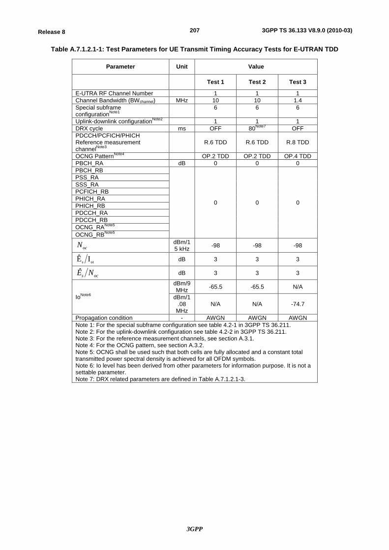
3GPP
207Release 8 3GPP TS 36.133 V8.9.0 (2010-03)
Table A.7.1.2.1-1: Test Parameters for UE Transmit Timing Accuracy Tests for E-UTRAN TDD
Parameter Unit Value
Test 1 Test 2 Test 3
E-UTRA RF Channel Number 1 1 1 Channel Bandwidth (BWchannel) MHz 10 10 1.4 Special subframe configurationNote1
6 6 6
Uplink-downlink configurationNote2 1 1 1 DRX cycle ms OFF 80Note7 OFF PDCCH/PCFICH/PHICH Reference measurement channelNote3
R.6 TDD R.6 TDD R.8 TDD
OCNG PatternNote4 OP.2 TDD OP.2 TDD OP.4 TDD PBCH_RA dB 0 0 0 PBCH_RB
0 0 0
PSS_RA SSS_RA PCFICH_RB PHICH_RA PHICH_RB PDCCH_RA PDCCH_RB OCNG_RANote5 OCNG_RBNote5
ocN dBm/15 kHz -98 -98 -98
ots IÊ dB 3 3 3
ocs NÊ dB 3 3 3
IoNote6
dBm/9 MHz -65.5 -65.5 N/A
dBm/1.08
MHz N/A N/A -74.7
Propagation condition - AWGN AWGN AWGN Note 1: For the special subframe configuration see table 4.2-1 in 3GPP TS 36.211. Note 2: For the uplink-downlink configuration see table 4.2-2 in 3GPP TS 36.211. Note 3: For the reference measurement channels, see section A.3.1. Note 4: For the OCNG pattern, see section A.3.2. Note 5: OCNG shall be used such that both cells are fully allocated and a constant total transmitted power spectral density is achieved for all OFDM symbols. Note 6: Io level has been derived from other parameters for information purpose. It is not a settable parameter. Note 7: DRX related parameters are defined in Table A.7.1.2.1-3.
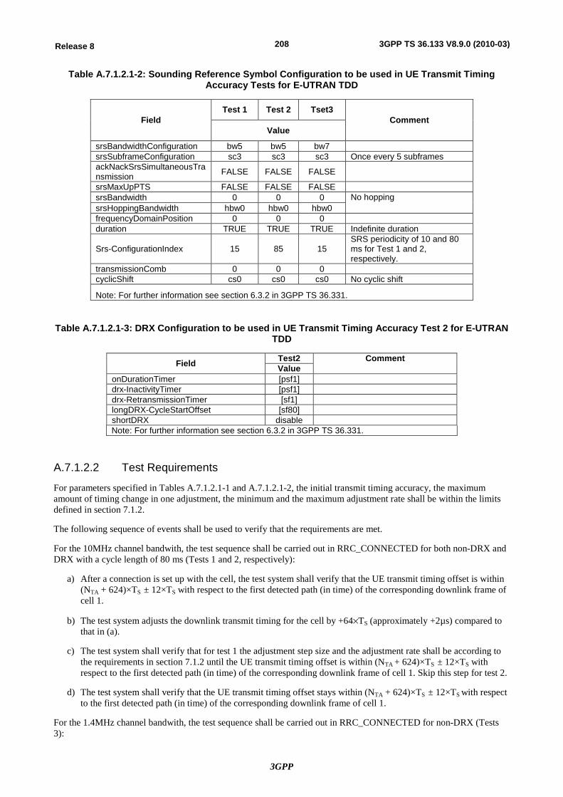
3GPP
208Release 8 3GPP TS 36.133 V8.9.0 (2010-03)
Table A.7.1.2.1-2: Sounding Reference Symbol Configuration to be used in UE Transmit Timing Accuracy Tests for E-UTRAN TDD
Field Test 1 Test 2 Tset3
Comment Value
srsBandwidthConfiguration bw5 bw5 bw7 srsSubframeConfiguration sc3 sc3 sc3 Once every 5 subframes ackNackSrsSimultaneousTransmission FALSE FALSE FALSE
srsMaxUpPTS FALSE FALSE FALSE srsBandwidth 0 0 0 No hopping srsHoppingBandwidth hbw0 hbw0 hbw0 frequencyDomainPosition 0 0 0 duration TRUE TRUE TRUE Indefinite duration
Srs-ConfigurationIndex 15 85 15 SRS periodicity of 10 and 80 ms for Test 1 and 2, respectively.
transmissionComb 0 0 0 cyclicShift cs0 cs0 cs0 No cyclic shift
Note: For further information see section 6.3.2 in 3GPP TS 36.331.
Table A.7.1.2.1-3: DRX Configuration to be used in UE Transmit Timing Accuracy Test 2 for E-UTRAN TDD
Field Test2 Comment Value
onDurationTimer [psf1] drx-InactivityTimer [psf1] drx-RetransmissionTimer [sf1] longDRX-CycleStartOffset [sf80] shortDRX disable Note: For further information see section 6.3.2 in 3GPP TS 36.331.
A.7.1.2.2 Test Requirements
For parameters specified in Tables A.7.1.2.1-1 and A.7.1.2.1-2, the initial transmit timing accuracy, the maximum amount of timing change in one adjustment, the minimum and the maximum adjustment rate shall be within the limits defined in section 7.1.2.
The following sequence of events shall be used to verify that the requirements are met.
For the 10MHz channel bandwith, the test sequence shall be carried out in RRC_CONNECTED for both non-DRX and DRX with a cycle length of 80 ms (Tests 1 and 2, respectively):
a) After a connection is set up with the cell, the test system shall verify that the UE transmit timing offset is within (NTA + 624)×TS ± 12×TS with respect to the first detected path (in time) of the corresponding downlink frame of cell 1.
b) The test system adjusts the downlink transmit timing for the cell by +64´TS (approximately +2µs) compared to that in (a).
c) The test system shall verify that for test 1 the adjustment step size and the adjustment rate shall be according to the requirements in section 7.1.2 until the UE transmit timing offset is within (NTA + 624)×TS ± 12×TS with respect to the first detected path (in time) of the corresponding downlink frame of cell 1. Skip this step for test 2.
d) The test system shall verify that the UE transmit timing offset stays within (NTA + 624)×TS ± 12×TS with respect to the first detected path (in time) of the corresponding downlink frame of cell 1.
For the 1.4MHz channel bandwith, the test sequence shall be carried out in RRC_CONNECTED for non-DRX (Tests 3):
3GPP
209Release 8 3GPP TS 36.133 V8.9.0 (2010-03)
a) After a connection is set up with the cell, the test system shall verify that the UE transmit timing offset is within (NTA +624)×TS ± 24×TS with respect to the first detected path (in time) of the corresponding downlink frame of cell 1.
b) The test system adjusts the downlink transmit timing for the cell by +128´TS (approximately +4µs) compared to that in (a).
c) The test system shall verify that the adjustment step size and the adjustment rate shall be according to the requirements in section 7.1.2 until the UE transmit timing offset is within (NTA +624)×TS ± 24×TS with respect to the first detected path (in time) of the corresponding downlink frame of cell 1.
d) The test system shall verify that the UE transmit timing offset stays within (NTA +624)×TS ± 24×TS with respect to the first detected path (in time) of the corresponding downlink frame of cell 1.
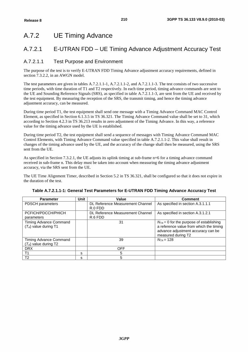
3GPP
210Release 8 3GPP TS 36.133 V8.9.0 (2010-03)
A.7.2 UE Timing Advance
A.7.2.1 E-UTRAN FDD – UE Timing Advance Adjustment Accuracy Test
A.7.2.1.1 Test Purpose and Environment
The purpose of the test is to verify E-UTRAN FDD Timing Advance adjustment accuracy requirements, defined in section 7.3.2.2, in an AWGN model.
The test parameters are given in tables A.7.2.1.1-1, A.7.2.1.1-2, and A.7.2.1.1-3. The test consists of two successive time periods, with time duration of T1 and T2 respectively. In each time period, timing advance commands are sent to the UE and Sounding Reference Signals (SRS), as specified in table A.7.2.1.1-3, are sent from the UE and received by the test equipment. By measuring the reception of the SRS, the transmit timing, and hence the timing advance adjustment accuracy, can be measured.
During time period T1, the test equipment shall send one message with a Timing Advance Command MAC Control Element, as specified in Section 6.1.3.5 in TS 36.321. The Timing Advance Command value shall be set to 31, which according to Section 4.2.3 in TS 36.213 results in zero adjustment of the Timing Advance. In this way, a reference value for the timing advance used by the UE is established.
During time period T2, the test equipment shall send a sequence of messages with Timing Advance Command MAC Control Elements, with Timing Advance Command value specified in table A.7.2.1.1-2. This value shall result in changes of the timing advance used by the UE, and the accuracy of the change shall then be measured, using the SRS sent from the UE.
As specified in Section 7.3.2.1, the UE adjusts its uplink timing at sub-frame n+6 for a timing advance command received in sub-frame n. This delay must be taken into account when measuring the timing advance adjustment accuracy, via the SRS sent from the UE.
The UE Time Alignment Timer, described in Section 5.2 in TS 36.321, shall be configured so that it does not expire in the duration of the test.
Table A.7.2.1.1-1: General Test Parameters for E-UTRAN FDD Timing Advance Accuracy Test
Parameter Unit Value Comment PDSCH parameters DL Reference Measurement Channel
R.0 FDD As specified in section A.3.1.1.1
PCFICH/PDCCH/PHICH parameters
DL Reference Measurement Channel R.6 FDD
As specified in section A.3.1.2.1
Timing Advance Command (TA) value during T1
31 NTA = 0 for the purpose of establishing a reference value from which the timing advance adjustment accuracy can be measured during T2
Timing Advance Command (TA) value during T2
39 NTA = 128
DRX OFF T1 s 5 T2 s 5
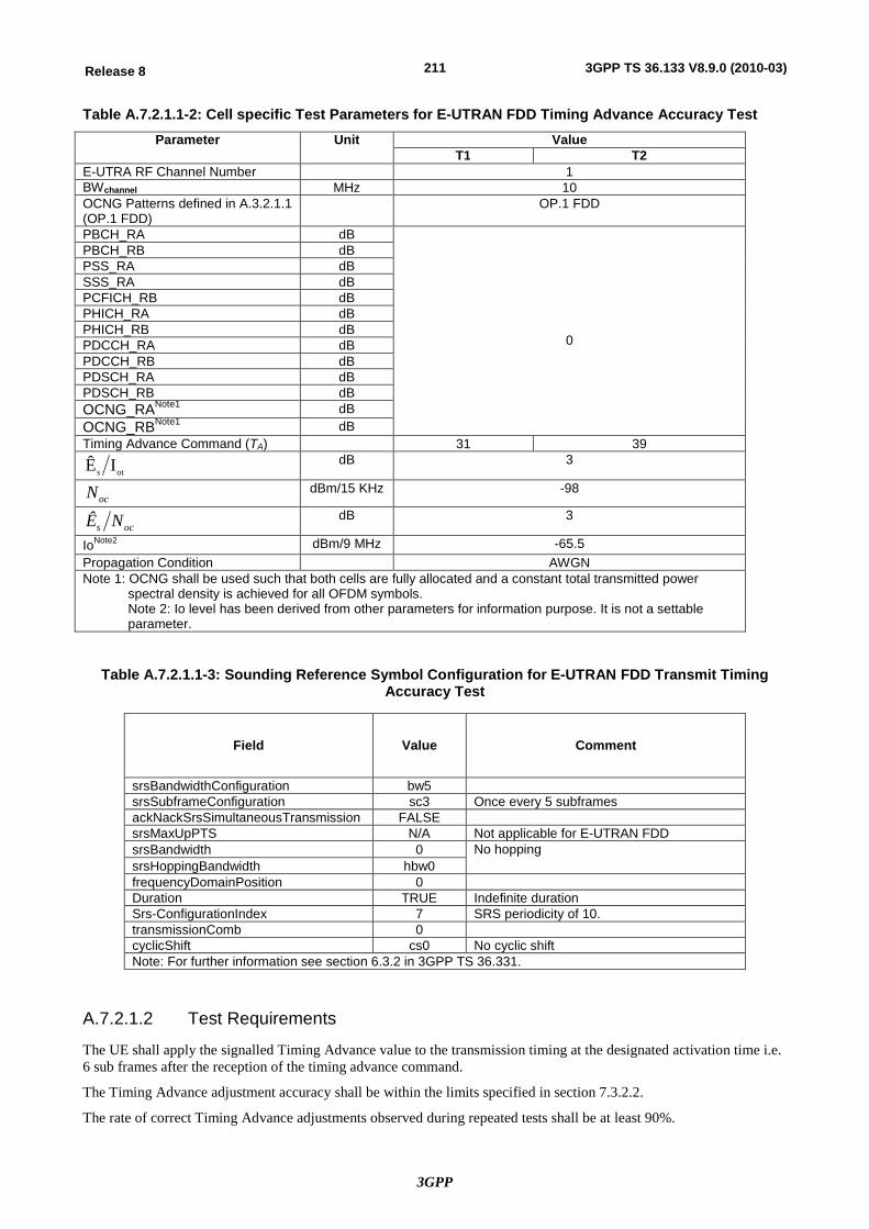
3GPP
211Release 8 3GPP TS 36.133 V8.9.0 (2010-03)
Table A.7.2.1.1-2: Cell specific Test Parameters for E-UTRAN FDD Timing Advance Accuracy Test Parameter Unit Value
T1 T2 E-UTRA RF Channel Number 1 BWchannel MHz 10 OCNG Patterns defined in A.3.2.1.1 (OP.1 FDD)
OP.1 FDD
PBCH_RA dB
0
PBCH_RB dB PSS_RA dB SSS_RA dB PCFICH_RB dB PHICH_RA dB PHICH_RB dB PDCCH_RA dB PDCCH_RB dB PDSCH_RA dB PDSCH_RB dB OCNG_RANote1 dB OCNG_RBNote1 dB Timing Advance Command (TA) 31 39
ots IÊ dB 3
ocN dBm/15 KHz -98
ocs NÊ dB 3
IoNote2 dBm/9 MHz -65.5 Propagation Condition AWGN Note 1: OCNG shall be used such that both cells are fully allocated and a constant total transmitted power
spectral density is achieved for all OFDM symbols. Note 2: Io level has been derived from other parameters for information purpose. It is not a settable parameter.
Table A.7.2.1.1-3: Sounding Reference Symbol Configuration for E-UTRAN FDD Transmit Timing Accuracy Test
Field Value Comment
srsBandwidthConfiguration bw5 srsSubframeConfiguration sc3 Once every 5 subframes ackNackSrsSimultaneousTransmission FALSE srsMaxUpPTS N/A Not applicable for E-UTRAN FDD srsBandwidth 0 No hopping srsHoppingBandwidth hbw0 frequencyDomainPosition 0 Duration TRUE Indefinite duration Srs-ConfigurationIndex 7 SRS periodicity of 10. transmissionComb 0 cyclicShift cs0 No cyclic shift Note: For further information see section 6.3.2 in 3GPP TS 36.331.
A.7.2.1.2 Test Requirements
The UE shall apply the signalled Timing Advance value to the transmission timing at the designated activation time i.e. 6 sub frames after the reception of the timing advance command.
The Timing Advance adjustment accuracy shall be within the limits specified in section 7.3.2.2.
The rate of correct Timing Advance adjustments observed during repeated tests shall be at least 90%.
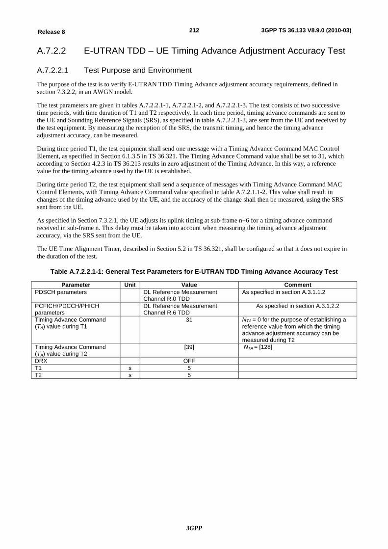
3GPP
212Release 8 3GPP TS 36.133 V8.9.0 (2010-03)
A.7.2.2 E-UTRAN TDD – UE Timing Advance Adjustment Accuracy Test
A.7.2.2.1 Test Purpose and Environment
The purpose of the test is to verify E-UTRAN TDD Timing Advance adjustment accuracy requirements, defined in section 7.3.2.2, in an AWGN model.
The test parameters are given in tables A.7.2.2.1-1, A.7.2.2.1-2, and A.7.2.2.1-3. The test consists of two successive time periods, with time duration of T1 and T2 respectively. In each time period, timing advance commands are sent to the UE and Sounding Reference Signals (SRS), as specified in table A.7.2.2.1-3, are sent from the UE and received by the test equipment. By measuring the reception of the SRS, the transmit timing, and hence the timing advance adjustment accuracy, can be measured.
During time period T1, the test equipment shall send one message with a Timing Advance Command MAC Control Element, as specified in Section 6.1.3.5 in TS 36.321. The Timing Advance Command value shall be set to 31, which according to Section 4.2.3 in TS 36.213 results in zero adjustment of the Timing Advance. In this way, a reference value for the timing advance used by the UE is established.
During time period T2, the test equipment shall send a sequence of messages with Timing Advance Command MAC Control Elements, with Timing Advance Command value specified in table A.7.2.1.1-2. This value shall result in changes of the timing advance used by the UE, and the accuracy of the change shall then be measured, using the SRS sent from the UE.
As specified in Section 7.3.2.1, the UE adjusts its uplink timing at sub-frame n+6 for a timing advance command received in sub-frame n. This delay must be taken into account when measuring the timing advance adjustment accuracy, via the SRS sent from the UE.
The UE Time Alignment Timer, described in Section 5.2 in TS 36.321, shall be configured so that it does not expire in the duration of the test.
Table A.7.2.2.1-1: General Test Parameters for E-UTRAN TDD Timing Advance Accuracy Test
Parameter Unit Value Comment PDSCH parameters DL Reference Measurement
Channel R.0 TDD As specified in section A.3.1.1.2
PCFICH/PDCCH/PHICH parameters
DL Reference Measurement Channel R.6 TDD
As specified in section A.3.1.2.2
Timing Advance Command (TA) value during T1
31 NTA = 0 for the purpose of establishing a reference value from which the timing advance adjustment accuracy can be measured during T2
Timing Advance Command (TA) value during T2
[39] NTA = [128]
DRX OFF T1 s 5 T2 s 5
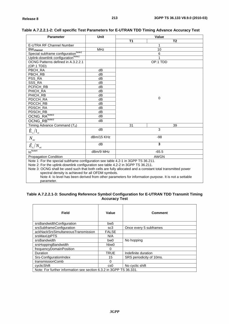
3GPP
213Release 8 3GPP TS 36.133 V8.9.0 (2010-03)
Table A.7.2.2.1-2: Cell specific Test Parameters for E-UTRAN TDD Timing Advance Accuracy Test Parameter Unit Value
T1 T2 E-UTRA RF Channel Number 1 BWchannel MHz 10 Special subframe configurationNote1 6 Uplink-downlink configurationNote2 1 OCNG Patterns defined in A.3.2.2.1 (OP.1 TDD)
OP.1 TDD
PBCH_RA dB
0
PBCH_RB dB PSS_RA dB SSS_RA dB PCFICH_RB dB PHICH_RA dB PHICH_RB dB PDCCH_RA dB PDCCH_RB dB PDSCH_RA dB PDSCH_RB dB OCNG_RANote3 dB OCNG_RBNote3 dB Timing Advance Command (TA) 31 39
ots IÊ dB 3
ocN dBm/15 KHz -98
ocs NÊ dB 3
IoNote4 dBm/9 MHz -65.5 Propagation Condition AWGN Note 1: For the special subframe configuration see table 4.2-1 in 3GPP TS 36.211. Note 2: For the uplink-downlink configuration see table 4.2-2 in 3GPP TS 36.211. Note 3: OCNG shall be used such that both cells are fully allocated and a constant total transmitted power
spectral density is achieved for all OFDM symbols. Note 4: Io level has been derived from other parameters for information purpose. It is not a settable parameter.
Table A.7.2.2.1-3: Sounding Reference Symbol Configuration for E-UTRAN TDD Transmit Timing Accuracy Test
Field Value Comment
srsBandwidthConfiguration bw5 srsSubframeConfiguration sc3 Once every 5 subframes ackNackSrsSimultaneousTransmission FALSE srsMaxUpPTS N/A srsBandwidth bw0 No hopping srsHoppingBandwidth hbw0 frequencyDomainPosition 0 Duration TRUE Indefinite duration Srs-ConfigurationIndex 15 SRS periodicity of 10ms. transmissionComb 0 cyclicShift cs0 No cyclic shift Note: For further information see section 6.3.2 in 3GPP TS 36.331.
3GPP
214Release 8 3GPP TS 36.133 V8.9.0 (2010-03)
A.7.2.2.2 Test Requirements The UE shall apply the signalled Timing Advance value to the transmission timing at the designated activation time i.e. 6 sub frames after the reception of the timing advance command.
The Timing Advance adjustment accuracy shall be within the limits specified in section 7.3.2.2.
A.7.3 Radio Link Monitoring
A.7.3.1 E-UTRAN FDD Radio Link Monitoring Test for Out-of-sync
A.7.3.1.1 Test Purpose and Environment
The purpose of this test is to verify that the UE properly detects the out of sync and in sync for the purpose of monitoring downlink radio link quality of the serving cell. This test will partly verify the E-UTRAN FDD radio link monitoring requirements in section 7.6.
The test parameters are given in Tables A.7.3.1.1-1, A.7.3.1.1-2 and A.7.3.1.1-3 below. There is one cell (cell 1), which is the active cell, in the test. The test consists of three successive time periods, with time duration of T1, T2 and T3 respectively. Figure A.7.3.1.1-4 shows the variation of the downlink SNR in the active cell to emulate out-of-sync and in-sync states. Prior to the start of the time duration T1, the UE shall be fully synchronized to cell 1. The UE shall be configured for periodic CQI reporting in PUCCH 1-0 mode with a reporting periodicity of 2 ms.
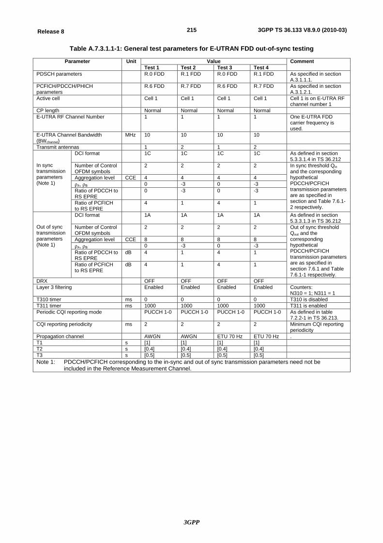
3GPP
215Release 8 3GPP TS 36.133 V8.9.0 (2010-03)
Table A.7.3.1.1-1: General test parameters for E-UTRAN FDD out-of-sync testing
Parameter Unit Value Comment Test 1 Test 2 Test 3 Test 4
PDSCH parameters R.0 FDD R.1 FDD R.0 FDD R.1 FDD As specified in section A.3.1.1.1.
PCFICH/PDCCH/PHICH parameters
R.6 FDD R.7 FDD R.6 FDD R.7 FDD As specified in section A.3.1.2.1.
Active cell Cell 1 Cell 1 Cell 1 Cell 1 Cell 1 is on E-UTRA RF channel number 1
CP length Normal Normal Normal Normal E-UTRA RF Channel Number 1 1 1 1 One E-UTRA FDD
carrier frequency is used.
E-UTRA Channel Bandwidth (BWchannel)
MHz 10 10 10 10
Transmit antennas 1 2 1 2 In sync transmission parameters (Note 1)
DCI format 1C 1C 1C 1C As defined in section 5.3.3.1.4 in TS 36.212
Number of Control OFDM symbols
2 2 2 2 In sync threshold Qin and the corresponding hypothetical PDCCH/PCFICH transmission parameters are as specified in section and Table 7.6.1-2 respectively.
Aggregation level CCE 4 4 4 4 rA, rB 0 -3 0 -3 Ratio of PDCCH to RS EPRE
0 -3 0 -3
Ratio of PCFICH to RS EPRE
4 1 4 1
Out of sync transmission parameters (Note 1)
DCI format 1A 1A 1A 1A As defined in section 5.3.3.1.3 in TS 36.212
Number of Control OFDM symbols
2 2 2 2 Out of sync threshold Qout and the corresponding hypothetical PDCCH/PCFICH transmission parameters are as specified in section 7.6.1 and Table 7.6.1-1 respectively.
Aggregation level CCE 8 8 8 8 rA, rB 0 -3 0 -3 Ratio of PDCCH to RS EPRE
dB 4 1 4 1
Ratio of PCFICH to RS EPRE
dB 4 1 4 1
DRX OFF OFF OFF OFF Layer 3 filtering Enabled Enabled Enabled Enabled Counters:
N310 = 1; N311 = 1 T310 timer ms 0 0 0 0 T310 is disabled T311 timer ms 1000 1000 1000 1000 T311 is enabled Periodic CQI reporting mode PUCCH 1-0 PUCCH 1-0 PUCCH 1-0 PUCCH 1-0 As defined in table
7.2.2-1 in TS 36.213. CQI reporting periodicity ms 2 2 2 2 Minimum CQI reporting
periodicity Propagation channel AWGN AWGN ETU 70 Hz ETU 70 Hz . T1 s [1] [1] [1] [1] T2 s [0.4] [0.4] [0.4] [0.4] T3 s [0.5] [0.5] [0.5] [0.5] Note 1: PDCCH/PCFICH corresponding to the in-sync and out of sync transmission parameters need not be
included in the Reference Measurement Channel.
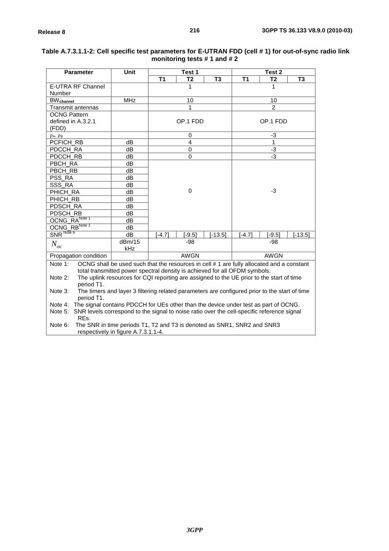
3GPP
216Release 8 3GPP TS 36.133 V8.9.0 (2010-03)
Table A.7.3.1.1-2: Cell specific test parameters for E-UTRAN FDD (cell # 1) for out-of-sync radio link monitoring tests # 1 and # 2
Parameter Unit Test 1 Test 2 T1 T2 T3 T1 T2 T3
E-UTRA RF Channel Number
1 1
BWchannel MHz 10 10 Transmit antennas 1 2 OCNG Pattern defined in A.3.2.1 (FDD)
OP.1 FDD
OP.1 FDD
rA, rB 0 -3 PCFICH_RB dB 4 1 PDCCH_RA dB 0 -3 PDCCH_RB dB 0 -3 PBCH_RA dB
0
-3
PBCH_RB dB PSS_RA dB SSS_RA dB PHICH_RA dB PHICH_RB dB PDSCH_RA dB PDSCH_RB dB OCNG_RANote 1 dB OCNG_RBNote 1 dB SNR Note 6 dB [-4.7] [-9.5] [-13.5] [-4.7] [-9.5] [-13.5]
ocN dBm/15 kHz
-98 -98
Propagation condition AWGN AWGN Note 1: OCNG shall be used such that the resources in cell # 1 are fully allocated and a constant
total transmitted power spectral density is achieved for all OFDM symbols. Note 2: The uplink resources for CQI reporting are assigned to the UE prior to the start of time
period T1. Note 3: The timers and layer 3 filtering related parameters are configured prior to the start of time
period T1. Note 4: The signal contains PDCCH for UEs other than the device under test as part of OCNG. Note 5: SNR levels correspond to the signal to noise ratio over the cell-specific reference signal
REs. Note 6: The SNR in time periods T1, T2 and T3 is denoted as SNR1, SNR2 and SNR3
respectively in figure A.7.3.1.1-4.
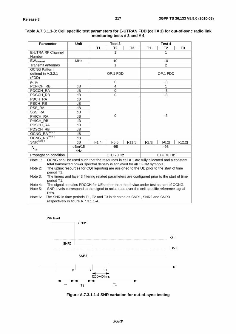
3GPP
217Release 8 3GPP TS 36.133 V8.9.0 (2010-03)
Table A.7.3.1.1-3: Cell specific test parameters for E-UTRAN FDD (cell # 1) for out-of-sync radio link monitoring tests # 3 and # 4
Parameter Unit Test 3 Test 4 T1 T2 T3 T1 T2 T3
E-UTRA RF Channel Number
1 1
BWchannel MHz 10 10 Transmit antennas 1 2 OCNG Pattern defined in A.3.2.1 (FDD)
OP.1 FDD
OP.1 FDD
rA, rB 0 -3 PCFICH_RB dB 4 1 PDCCH_RA dB 0 -3 PDCCH_RB dB 0 -3 PBCH_RA dB
0
-3
PBCH_RB dB PSS_RA dB SSS_RA dB PHICH_RA dB PHICH_RB dB PDSCH_RA dB PDSCH_RB dB OCNG_RANote 1 dB OCNG_RBNote 1 dB SNR Note 6 dB [-1.4] [-5.5] [-11.5] [-2.3] [-6.2] [-12.2]
ocN dBm/15 kHz
-98 -98
Propagation condition ETU 70 Hz ETU 70 Hz Note 1: OCNG shall be used such that the resources in cell # 1 are fully allocated and a constant
total transmitted power spectral density is achieved for all OFDM symbols. Note 2: The uplink resources for CQI reporting are assigned to the UE prior to the start of time
period T1. Note 3: The timers and layer 3 filtering related parameters are configured prior to the start of time
period T1. Note 4: The signal contains PDCCH for UEs other than the device under test as part of OCNG. Note 5: SNR levels correspond to the signal to noise ratio over the cell-specific reference signal
REs. Note 6: The SNR in time periods T1, T2 and T3 is denoted as SNR1, SNR2 and SNR3
respectively in figure A.7.3.1.1-4.
Figure A.7.3.1.1-4 SNR variation for out-of-sync testing
3GPP
218Release 8 3GPP TS 36.133 V8.9.0 (2010-03)
(Editor’s note: Behaviours of continuing the transmissions of PUCHH when T310 timer is running could be verified in the tests for in-sync.)
A.7.3.1.2 Test Requirements
The UE behaviour in each test during time durations T1, T2 and T3 shall be as follows:
During time duration T1 and T2 the UE shall continuously report CQI according to the configured CQI mode (PUCCH 1-0) with a periodicity of 2 ms.
The UE shall stop reporting the CQI within [200 + 40] ms from the start of the time duration T3.
The rate of correct events observed during repeated tests shall be at least 90%.
A.7.3.2 E-UTRAN FDD Radio Link Monitoring Test for In-sync
A.7.3.2.1 Test Purpose and Environment
The purpose of this test is to verify that the UE properly detects the out of sync and in sync for the purpose of monitoring downlink radio link quality of the serving cell. This test will partly verify the E-UTRAN FDD radio link monitoring requirements in section 7.6.
The test parameters are given in Tables A.7.3.2.1-1 and A.7.3.2.1-2 below. There is one cell (cell 1), which is the active cell, in the test. The test consists of five successive time periods, with time duration of T1, T2, T3, T4 and T5 respectively. Figure A.7.3.2.1-3 shows the variation of the downlink SNR in the active cell to emulate out-of-sync and in-sync states. Prior to the start of the time duration T1, the UE shall be fully synchronized to cell 1. The UE shall be configured for periodic CQI reporting in PUCCH 1-0 mode with a reporting periodicity of 2 ms.

3GPP
219Release 8 3GPP TS 36.133 V8.9.0 (2010-03)
Table A.7.3.2.1-1: General test parameters for E-UTRAN FDD in-sync testing
Parameter Unit Value Comment Test 1 Test 2
PDSCH parameters R.0 FDD R.1 FDD As specified in section A.3.1.1.1.
PCFICH/PDCCH/PHICH parameters
R.6 FDD R.7 FDD As specified in section A.3.1.2.1.
Active cell Cell 1 Cell 1 Cell 1 is on E-UTRA RF channel number 1
CP length Normal Normal E-UTRA RF Channel Number 1 1 One E-UTRA FDD carrier
frequency is used. E-UTRA Channel Bandwidth (BWchannel)
MHz 10 10
Transmit antennas 1 2 In sync transmission parameters (Note 1)
DCI format 1C 1C As defined in section 5.3.3.1.4 in TS 36.212
Number of Control OFDM symbols
2 2 In sync threshold Qin and the corresponding hypothetical PDCCH/PCFICH transmission parameters are as specified in section and Table 7.6.1-2 respectively.
Aggregation level CCE 4 4 rA, rB 0 -3 Ratio of PDCCH to RS EPRE
0 -3
Ratio of PCFICH to RS EPRE
4 1
Out of sync transmission parameters (Note 1)
DCI format 1A 1A As defined in section 5.3.3.1.3 in TS 36.212
Number of Control OFDM symbols
2 2 Out of sync threshold Qout and the corresponding hypothetical PDCCH/PCFICH transmission parameters are as specified in section 7.6.1 and Table 7.6.1-1 respectively.
Aggregation level CCE 8 8 rA, rB 0 -3
Ratio of PDCCH to RS EPRE
dB 4 1
Ratio of PCFICH to RS EPRE
dB 4 1
DRX OFF OFF Layer 3 filtering Enabled Enabled Counters:
N310 = 1; N311 = 1 T310 timer ms [2000] [2000] T310 is enabled T311 timer ms 1000 1000 T311 is enabled Periodic CQI reporting mode PUCCH 1-0 PUCCH 1-0 As defined in table 7.2.2-1
in TS 36.213. CQI reporting periodicity ms 2 2 Minimum CQI reporting
periodicity Propagation channel ETU 70 Hz ETU 70 Hz T1 s [0.5] [0.5] T2 s [0.4] [0.4] T3 s [1.46] [1.46] T4 s [0.4] [0.4] T5 s [1] [1] Note 1: PDCCH/PCFICH corresponding to the in-sync and out of sync transmission
parameters need not be included in the Reference Measurement Channel.
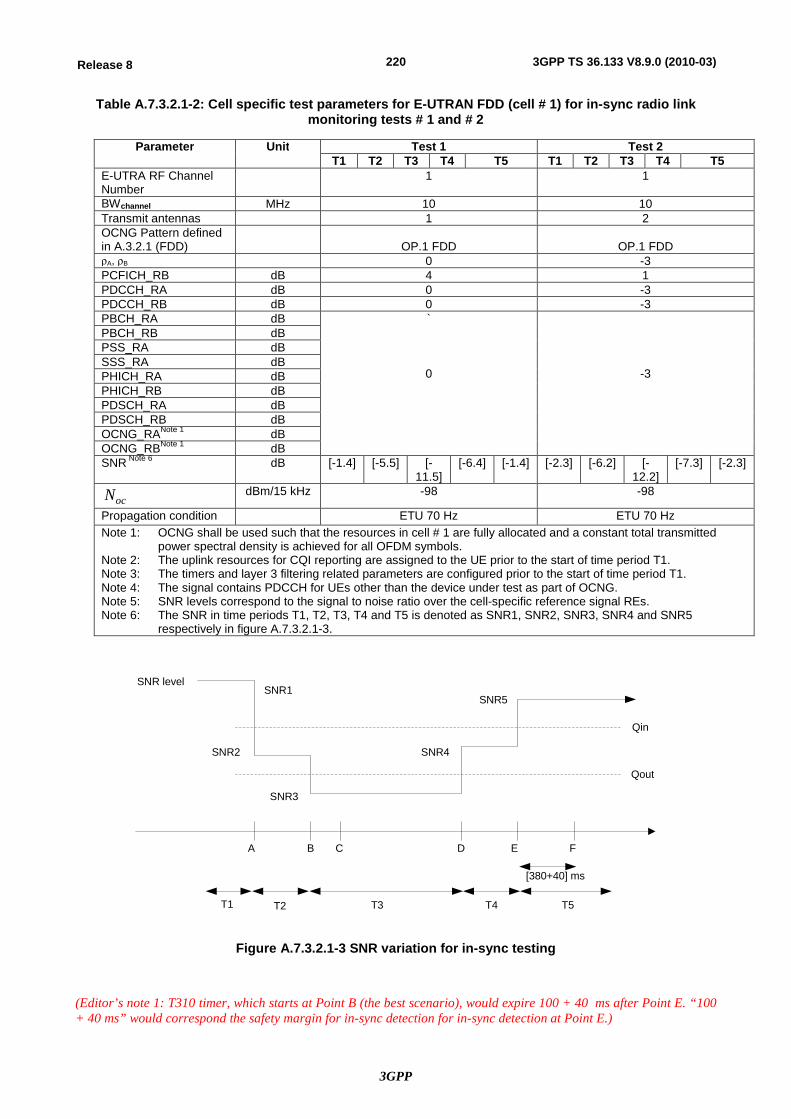
3GPP
220Release 8 3GPP TS 36.133 V8.9.0 (2010-03)
Table A.7.3.2.1-2: Cell specific test parameters for E-UTRAN FDD (cell # 1) for in-sync radio link monitoring tests # 1 and # 2
Parameter Unit Test 1 Test 2 T1 T2 T3 T4 T5 T1 T2 T3 T4 T5
E-UTRA RF Channel Number
1 1
BWchannel MHz 10 10 Transmit antennas 1 2 OCNG Pattern defined in A.3.2.1 (FDD)
OP.1 FDD
OP.1 FDD
rA, rB 0 -3 PCFICH_RB dB 4 1 PDCCH_RA dB 0 -3 PDCCH_RB dB 0 -3 PBCH_RA dB `
0
-3
PBCH_RB dB PSS_RA dB SSS_RA dB PHICH_RA dB PHICH_RB dB PDSCH_RA dB PDSCH_RB dB OCNG_RANote 1 dB OCNG_RBNote 1 dB SNR Note 6 dB [-1.4] [-5.5] [-
11.5] [-6.4] [-1.4] [-2.3] [-6.2] [-
12.2] [-7.3] [-2.3]
ocN dBm/15 kHz -98 -98
Propagation condition ETU 70 Hz ETU 70 Hz Note 1: OCNG shall be used such that the resources in cell # 1 are fully allocated and a constant total transmitted
power spectral density is achieved for all OFDM symbols. Note 2: The uplink resources for CQI reporting are assigned to the UE prior to the start of time period T1. Note 3: The timers and layer 3 filtering related parameters are configured prior to the start of time period T1. Note 4: The signal contains PDCCH for UEs other than the device under test as part of OCNG. Note 5: SNR levels correspond to the signal to noise ratio over the cell-specific reference signal REs. Note 6: The SNR in time periods T1, T2, T3, T4 and T5 is denoted as SNR1, SNR2, SNR3, SNR4 and SNR5
respectively in figure A.7.3.2.1-3.
Qin
Qout
SNR level
A B C D E F
T1 T2 T3 T4 T5
[380+40] ms
SNR1
SNR2
SNR3
SNR4
SNR5
Figure A.7.3.2.1-3 SNR variation for in-sync testing
(Editor’s note 1: T310 timer, which starts at Point B (the best scenario), would expire 100 + 40 ms after Point E. “100 + 40 ms” would correspond the safety margin for in-sync detection for in-sync detection at Point E.)
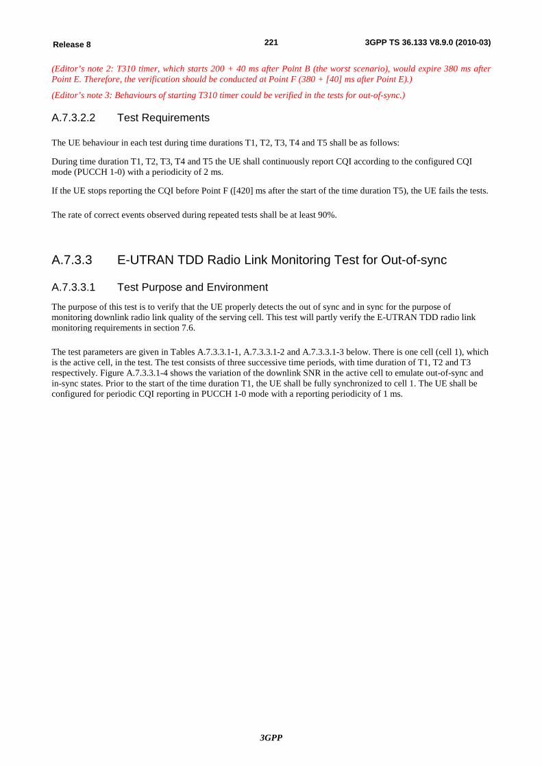
3GPP
221Release 8 3GPP TS 36.133 V8.9.0 (2010-03)
(Editor’s note 2: T310 timer, which starts 200 + 40 ms after Point B (the worst scenario), would expire 380 ms after Point E. Therefore, the verification should be conducted at Point F (380 + [40] ms after Point E).)
(Editor’s note 3: Behaviours of starting T310 timer could be verified in the tests for out-of-sync.)
A.7.3.2.2 Test Requirements
The UE behaviour in each test during time durations T1, T2, T3, T4 and T5 shall be as follows:
During time duration T1, T2, T3, T4 and T5 the UE shall continuously report CQI according to the configured CQI mode (PUCCH 1-0) with a periodicity of 2 ms.
If the UE stops reporting the CQI before Point F ([420] ms after the start of the time duration T5), the UE fails the tests.
The rate of correct events observed during repeated tests shall be at least 90%.
A.7.3.3 E-UTRAN TDD Radio Link Monitoring Test for Out-of-sync
A.7.3.3.1 Test Purpose and Environment
The purpose of this test is to verify that the UE properly detects the out of sync and in sync for the purpose of monitoring downlink radio link quality of the serving cell. This test will partly verify the E-UTRAN TDD radio link monitoring requirements in section 7.6.
The test parameters are given in Tables A.7.3.3.1-1, A.7.3.3.1-2 and A.7.3.3.1-3 below. There is one cell (cell 1), which is the active cell, in the test. The test consists of three successive time periods, with time duration of T1, T2 and T3 respectively. Figure A.7.3.3.1-4 shows the variation of the downlink SNR in the active cell to emulate out-of-sync and in-sync states. Prior to the start of the time duration T1, the UE shall be fully synchronized to cell 1. The UE shall be configured for periodic CQI reporting in PUCCH 1-0 mode with a reporting periodicity of 1 ms.
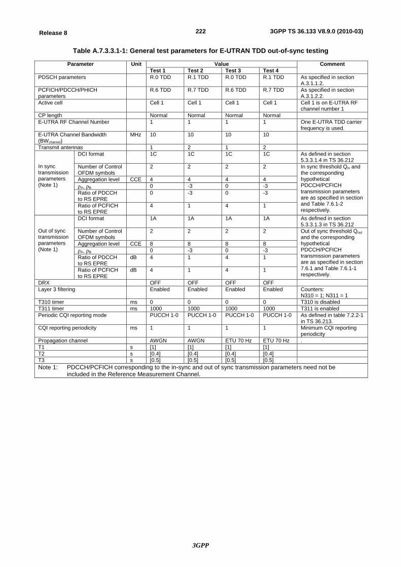
3GPP
222Release 8 3GPP TS 36.133 V8.9.0 (2010-03)
Table A.7.3.3.1-1: General test parameters for E-UTRAN TDD out-of-sync testing
Parameter Unit Value Comment Test 1 Test 2 Test 3 Test 4
PDSCH parameters R.0 TDD R.1 TDD R.0 TDD R.1 TDD As specified in section A.3.1.1.2.
PCFICH/PDCCH/PHICH parameters
R.6 TDD R.7 TDD R.6 TDD R.7 TDD As specified in section A.3.1.2.2.
Active cell Cell 1 Cell 1 Cell 1 Cell 1 Cell 1 is on E-UTRA RF channel number 1
CP length Normal Normal Normal Normal E-UTRA RF Channel Number 1 1 1 1 One E-UTRA TDD carrier
frequency is used. E-UTRA Channel Bandwidth (BWchannel)
MHz 10 10 10 10
Transmit antennas 1 2 1 2 In sync transmission parameters (Note 1)
DCI format 1C 1C 1C 1C As defined in section 5.3.3.1.4 in TS 36.212
Number of Control OFDM symbols
2 2 2 2 In sync threshold Qin and the corresponding hypothetical PDCCH/PCFICH transmission parameters are as specified in section and Table 7.6.1-2 respectively.
Aggregation level CCE 4 4 4 4 rA, rB 0 -3 0 -3 Ratio of PDCCH to RS EPRE
0 -3 0 -3
Ratio of PCFICH to RS EPRE
4 1 4 1
Out of sync transmission parameters (Note 1)
DCI format 1A 1A 1A 1A As defined in section 5.3.3.1.3 in TS 36.212
Number of Control OFDM symbols
2 2 2 2 Out of sync threshold Qout and the corresponding hypothetical PDCCH/PCFICH transmission parameters are as specified in section 7.6.1 and Table 7.6.1-1 respectively.
Aggregation level CCE 8 8 8 8 rA, rB 0 -3 0 -3 Ratio of PDCCH to RS EPRE
dB 4 1 4 1
Ratio of PCFICH to RS EPRE
dB 4 1 4 1
DRX OFF OFF OFF OFF Layer 3 filtering Enabled Enabled Enabled Enabled Counters:
N310 = 1; N311 = 1 T310 timer ms 0 0 0 0 T310 is disabled T311 timer ms 1000 1000 1000 1000 T311 is enabled Periodic CQI reporting mode PUCCH 1-0 PUCCH 1-0 PUCCH 1-0 PUCCH 1-0 As defined in table 7.2.2-1
in TS 36.213. CQI reporting periodicity ms 1 1 1 1 Minimum CQI reporting
periodicity Propagation channel AWGN AWGN ETU 70 Hz ETU 70 Hz . T1 s [1] [1] [1] [1] T2 s [0.4] [0.4] [0.4] [0.4] T3 s [0.5] [0.5] [0.5] [0.5] Note 1: PDCCH/PCFICH corresponding to the in-sync and out of sync transmission parameters need not be
included in the Reference Measurement Channel.

3GPP
223Release 8 3GPP TS 36.133 V8.9.0 (2010-03)
Table A.7.3.3.1-2: Cell specific test parameters for E-UTRAN TDD (cell # 1) for out-of-sync radio link monitoring tests # 1 and # 2
Parameter Unit Test 1 Test 2 T1 T2 T3 T1 T2 T3
E-UTRA RF Channel Number
1 1
BWchannel MHz 10 10 Transmit antennas 1 2 Special subframe configurationNote1
6 6
Uplink-downlink configurationNote2
1 1
OCNG Pattern defined in A.3.2.2 (TDD)
OP.1 TDD
OP.1 TDD
rA, rB 0 -3 PCFICH_RB dB 4 1 PDCCH_RA dB 0 -3 PDCCH_RB dB 0 -3 PBCH_RA dB
0
-3
PBCH_RB dB PSS_RA dB SSS_RA dB PHICH_RA dB PHICH_RB dB PDSCH_RA dB PDSCH_RB dB OCNG_RANote 3 dB OCNG_RBNote 3 dB SNR Note 8 dB [-5.1] [-9.1] [-13.1] [-5.2] [-9.2] [-13.2]
ocN dBm/15 kHz
-98 -98
Propagation condition AWGN AWGN Note 1: For the special subframe configuration see table 4.2-1 in 3GPP TS 36.211. Note 2: For the uplink-downlink configuration see table 4.2-2 in 3GPP TS 36.211. Note 3: OCNG shall be used such that the resources in cell # 1 are fully allocated and a constant
total transmitted power spectral density is achieved for all OFDM symbols. Note 4: The uplink resources for CQI reporting are assigned to the UE prior to the start of time
period T1. Note 5: The timers and layer 3 filtering related parameters are configured prior to the start of time
period T1. Note 6: The signal contains PDCCH for UEs other than the device under test as part of OCNG. Note 7: SNR levels correspond to the signal to noise ratio over the cell-specific reference signal
REs. Note 8: The SNR in time periods T1, T2 and T3 is denoted as SNR1, SNR2 and SNR3
respectively in figure A.7.3.3.1-4.
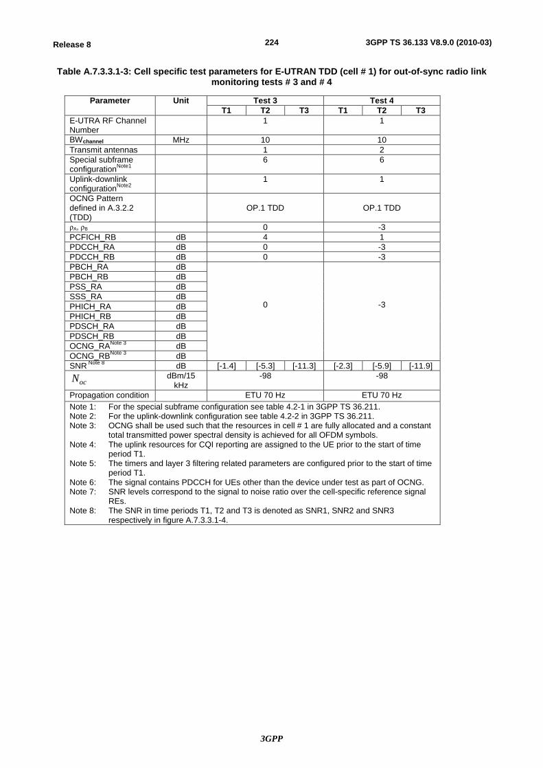
3GPP
224Release 8 3GPP TS 36.133 V8.9.0 (2010-03)
Table A.7.3.3.1-3: Cell specific test parameters for E-UTRAN TDD (cell # 1) for out-of-sync radio link monitoring tests # 3 and # 4
Parameter Unit Test 3 Test 4 T1 T2 T3 T1 T2 T3
E-UTRA RF Channel Number
1 1
BWchannel MHz 10 10 Transmit antennas 1 2 Special subframe configurationNote1
6 6
Uplink-downlink configurationNote2
1 1
OCNG Pattern defined in A.3.2.2 (TDD)
OP.1 TDD
OP.1 TDD
rA, rB 0 -3 PCFICH_RB dB 4 1 PDCCH_RA dB 0 -3 PDCCH_RB dB 0 -3 PBCH_RA dB
0
-3
PBCH_RB dB PSS_RA dB SSS_RA dB PHICH_RA dB PHICH_RB dB PDSCH_RA dB PDSCH_RB dB OCNG_RANote 3 dB OCNG_RBNote 3 dB SNR Note 8 dB [-1.4] [-5.3] [-11.3] [-2.3] [-5.9] [-11.9]
ocN dBm/15 kHz
-98 -98
Propagation condition ETU 70 Hz ETU 70 Hz Note 1: For the special subframe configuration see table 4.2-1 in 3GPP TS 36.211. Note 2: For the uplink-downlink configuration see table 4.2-2 in 3GPP TS 36.211. Note 3: OCNG shall be used such that the resources in cell # 1 are fully allocated and a constant
total transmitted power spectral density is achieved for all OFDM symbols. Note 4: The uplink resources for CQI reporting are assigned to the UE prior to the start of time
period T1. Note 5: The timers and layer 3 filtering related parameters are configured prior to the start of time
period T1. Note 6: The signal contains PDCCH for UEs other than the device under test as part of OCNG. Note 7: SNR levels correspond to the signal to noise ratio over the cell-specific reference signal
REs. Note 8: The SNR in time periods T1, T2 and T3 is denoted as SNR1, SNR2 and SNR3
respectively in figure A.7.3.3.1-4.
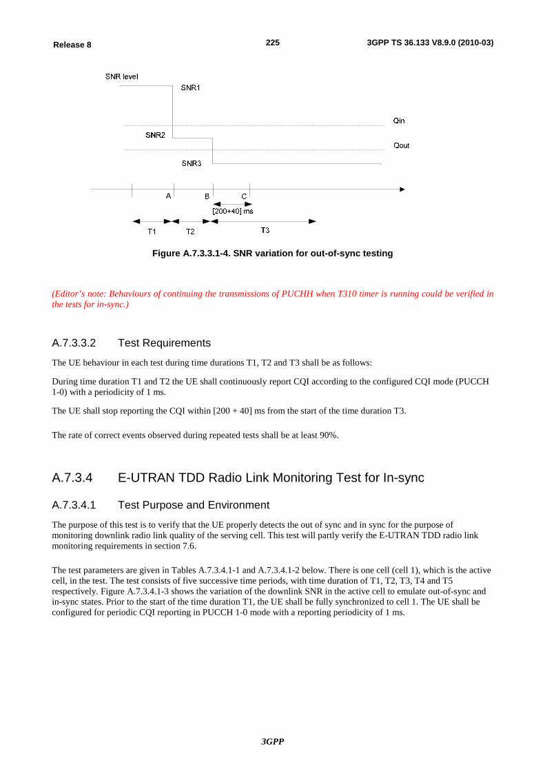
3GPP
225Release 8 3GPP TS 36.133 V8.9.0 (2010-03)
Figure A.7.3.3.1-4. SNR variation for out-of-sync testing
(Editor’s note: Behaviours of continuing the transmissions of PUCHH when T310 timer is running could be verified in the tests for in-sync.)
A.7.3.3.2 Test Requirements
The UE behaviour in each test during time durations T1, T2 and T3 shall be as follows:
During time duration T1 and T2 the UE shall continuously report CQI according to the configured CQI mode (PUCCH 1-0) with a periodicity of 1 ms.
The UE shall stop reporting the CQI within [200 + 40] ms from the start of the time duration T3.
The rate of correct events observed during repeated tests shall be at least 90%.
A.7.3.4 E-UTRAN TDD Radio Link Monitoring Test for In-sync
A.7.3.4.1 Test Purpose and Environment
The purpose of this test is to verify that the UE properly detects the out of sync and in sync for the purpose of monitoring downlink radio link quality of the serving cell. This test will partly verify the E-UTRAN TDD radio link monitoring requirements in section 7.6.
The test parameters are given in Tables A.7.3.4.1-1 and A.7.3.4.1-2 below. There is one cell (cell 1), which is the active cell, in the test. The test consists of five successive time periods, with time duration of T1, T2, T3, T4 and T5 respectively. Figure A.7.3.4.1-3 shows the variation of the downlink SNR in the active cell to emulate out-of-sync and in-sync states. Prior to the start of the time duration T1, the UE shall be fully synchronized to cell 1. The UE shall be configured for periodic CQI reporting in PUCCH 1-0 mode with a reporting periodicity of 1 ms.
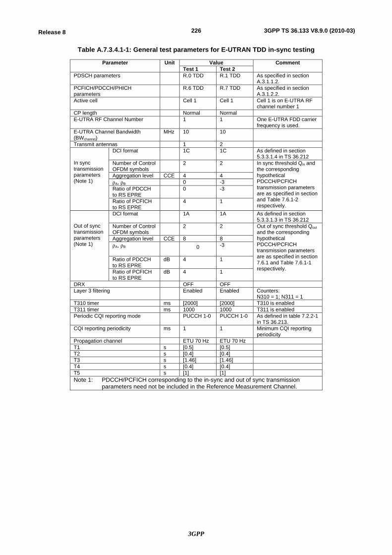
3GPP
226Release 8 3GPP TS 36.133 V8.9.0 (2010-03)
Table A.7.3.4.1-1: General test parameters for E-UTRAN TDD in-sync testing
Parameter Unit Value Comment Test 1 Test 2
PDSCH parameters R.0 TDD R.1 TDD As specified in section A.3.1.1.2.
PCFICH/PDCCH/PHICH parameters
R.6 TDD R.7 TDD As specified in section A.3.1.2.2.
Active cell Cell 1 Cell 1 Cell 1 is on E-UTRA RF channel number 1
CP length Normal Normal E-UTRA RF Channel Number 1 1 One E-UTRA FDD carrier
frequency is used. E-UTRA Channel Bandwidth (BWchannel)
MHz 10 10
Transmit antennas 1 2 In sync transmission parameters (Note 1)
DCI format 1C 1C As defined in section 5.3.3.1.4 in TS 36.212
Number of Control OFDM symbols
2 2 In sync threshold Qin and the corresponding hypothetical PDCCH/PCFICH transmission parameters are as specified in section and Table 7.6.1-2 respectively.
Aggregation level CCE 4 4 rA, rB 0 -3 Ratio of PDCCH to RS EPRE
0 -3
Ratio of PCFICH to RS EPRE
4 1
Out of sync transmission parameters (Note 1)
DCI format 1A 1A As defined in section 5.3.3.1.3 in TS 36.212
Number of Control OFDM symbols
2 2 Out of sync threshold Qout and the corresponding hypothetical PDCCH/PCFICH transmission parameters are as specified in section 7.6.1 and Table 7.6.1-1 respectively.
Aggregation level CCE 8 8 rA, rB 0 -3
Ratio of PDCCH to RS EPRE
dB 4 1
Ratio of PCFICH to RS EPRE
dB 4 1
DRX OFF OFF Layer 3 filtering Enabled Enabled Counters:
N310 = 1; N311 = 1 T310 timer ms [2000] [2000] T310 is enabled T311 timer ms 1000 1000 T311 is enabled Periodic CQI reporting mode PUCCH 1-0 PUCCH 1-0 As defined in table 7.2.2-1
in TS 36.213. CQI reporting periodicity ms 1 1 Minimum CQI reporting
periodicity Propagation channel ETU 70 Hz ETU 70 Hz T1 s [0.5] [0.5] T2 s [0.4] [0.4] T3 s [1.46] [1.46] T4 s [0.4] [0.4] T5 s [1] [1] Note 1: PDCCH/PCFICH corresponding to the in-sync and out of sync transmission
parameters need not be included in the Reference Measurement Channel.
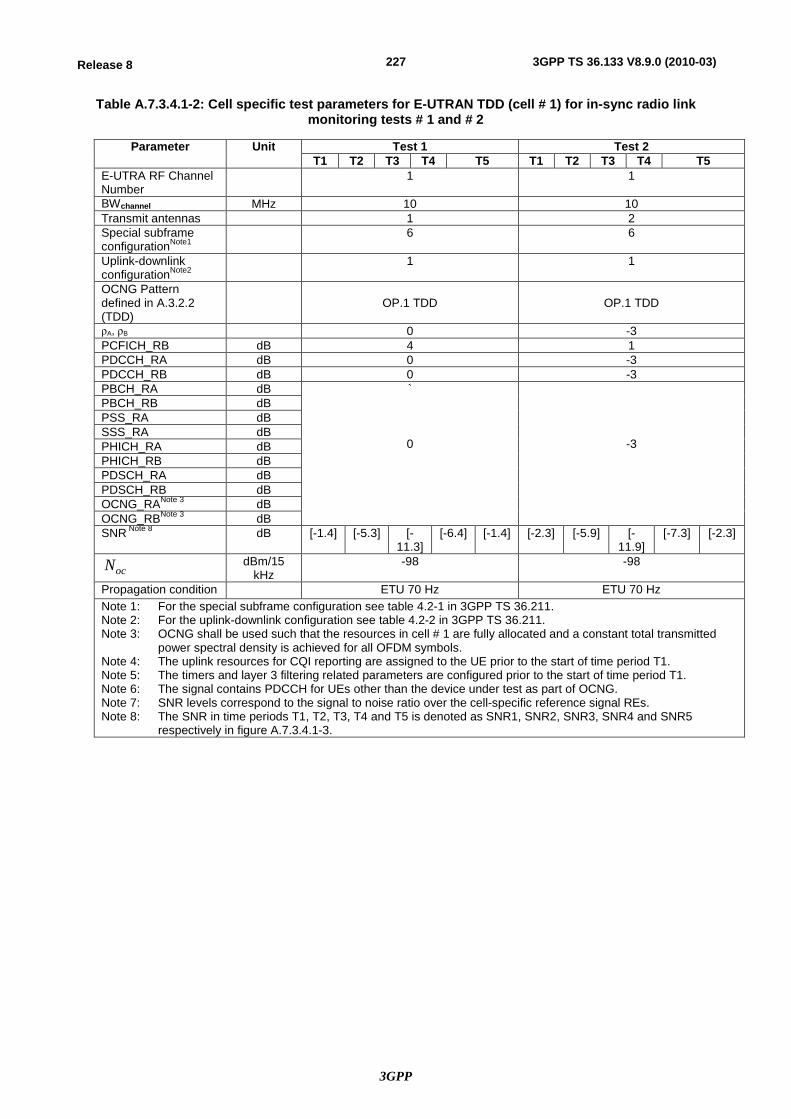
3GPP
227Release 8 3GPP TS 36.133 V8.9.0 (2010-03)
Table A.7.3.4.1-2: Cell specific test parameters for E-UTRAN TDD (cell # 1) for in-sync radio link monitoring tests # 1 and # 2
Parameter Unit Test 1 Test 2 T1 T2 T3 T4 T5 T1 T2 T3 T4 T5
E-UTRA RF Channel Number
1 1
BWchannel MHz 10 10 Transmit antennas 1 2 Special subframe configurationNote1
6 6
Uplink-downlink configurationNote2
1 1
OCNG Pattern defined in A.3.2.2 (TDD)
OP.1 TDD
OP.1 TDD
rA, rB 0 -3 PCFICH_RB dB 4 1 PDCCH_RA dB 0 -3 PDCCH_RB dB 0 -3 PBCH_RA dB `
0
-3
PBCH_RB dB PSS_RA dB SSS_RA dB PHICH_RA dB PHICH_RB dB PDSCH_RA dB PDSCH_RB dB OCNG_RANote 3 dB OCNG_RBNote 3 dB SNR Note 8 dB [-1.4] [-5.3] [-
11.3] [-6.4] [-1.4] [-2.3] [-5.9] [-
11.9] [-7.3] [-2.3]
ocN dBm/15 kHz
-98 -98
Propagation condition ETU 70 Hz ETU 70 Hz Note 1: For the special subframe configuration see table 4.2-1 in 3GPP TS 36.211. Note 2: For the uplink-downlink configuration see table 4.2-2 in 3GPP TS 36.211. Note 3: OCNG shall be used such that the resources in cell # 1 are fully allocated and a constant total transmitted
power spectral density is achieved for all OFDM symbols. Note 4: The uplink resources for CQI reporting are assigned to the UE prior to the start of time period T1. Note 5: The timers and layer 3 filtering related parameters are configured prior to the start of time period T1. Note 6: The signal contains PDCCH for UEs other than the device under test as part of OCNG. Note 7: SNR levels correspond to the signal to noise ratio over the cell-specific reference signal REs. Note 8: The SNR in time periods T1, T2, T3, T4 and T5 is denoted as SNR1, SNR2, SNR3, SNR4 and SNR5
respectively in figure A.7.3.4.1-3.
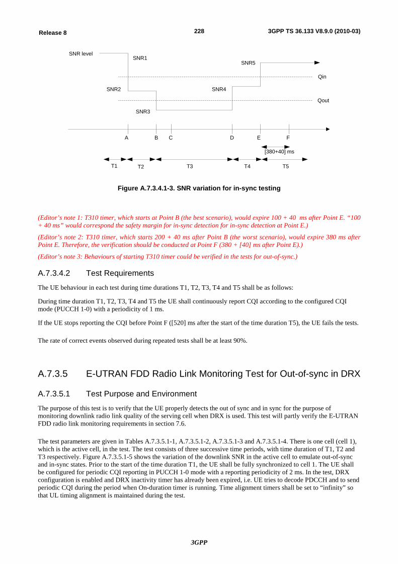
3GPP
228Release 8 3GPP TS 36.133 V8.9.0 (2010-03)
Qin
Qout
SNR level
A B C D E F
T1 T2 T3 T4 T5
[380+40] ms
SNR1
SNR2
SNR3
SNR4
SNR5
Figure A.7.3.4.1-3. SNR variation for in-sync testing
(Editor’s note 1: T310 timer, which starts at Point B (the best scenario), would expire 100 + 40 ms after Point E. “100 + 40 ms” would correspond the safety margin for in-sync detection for in-sync detection at Point E.)
(Editor’s note 2: T310 timer, which starts 200 + 40 ms after Point B (the worst scenario), would expire 380 ms after Point E. Therefore, the verification should be conducted at Point F (380 + [40] ms after Point E).)
(Editor’s note 3: Behaviours of starting T310 timer could be verified in the tests for out-of-sync.)
A.7.3.4.2 Test Requirements
The UE behaviour in each test during time durations T1, T2, T3, T4 and T5 shall be as follows:
During time duration T1, T2, T3, T4 and T5 the UE shall continuously report CQI according to the configured CQI mode (PUCCH 1-0) with a periodicity of 1 ms.
If the UE stops reporting the CQI before Point F ([520] ms after the start of the time duration T5), the UE fails the tests.
The rate of correct events observed during repeated tests shall be at least 90%.
A.7.3.5 E-UTRAN FDD Radio Link Monitoring Test for Out-of-sync in DRX
A.7.3.5.1 Test Purpose and Environment
The purpose of this test is to verify that the UE properly detects the out of sync and in sync for the purpose of monitoring downlink radio link quality of the serving cell when DRX is used. This test will partly verify the E-UTRAN FDD radio link monitoring requirements in section 7.6.
The test parameters are given in Tables A.7.3.5.1-1, A.7.3.5.1-2, A.7.3.5.1-3 and A.7.3.5.1-4. There is one cell (cell 1), which is the active cell, in the test. The test consists of three successive time periods, with time duration of T1, T2 and T3 respectively. Figure A.7.3.5.1-5 shows the variation of the downlink SNR in the active cell to emulate out-of-sync and in-sync states. Prior to the start of the time duration T1, the UE shall be fully synchronized to cell 1. The UE shall be configured for periodic CQI reporting in PUCCH 1-0 mode with a reporting periodicity of 2 ms. In the test, DRX configuration is enabled and DRX inactivity timer has already been expired, i.e. UE tries to decode PDCCH and to send periodic CQI during the period when On-duration timer is running. Time alignment timers shall be set to “infinity” so that UL timing alignment is maintained during the test.

3GPP
229Release 8 3GPP TS 36.133 V8.9.0 (2010-03)
Table A.7.3.5.1-1: General test parameters for E-UTRAN FDD out-of-sync tests in DRX
Parameter Unit Value Comment Test 1 Test 2
PDSCH parameters R.1 FDD R.0 FDD As specified in section A.3.1.1.1.
PCFICH/PDCCH/PHICH parameters
R.7 FDD R.6 FDD As specified in section A.3.1.2.1.
Active cell Cell 1 Cell 1 Cell 1 is on E-UTRA RF channel number 1
CP length Normal Normal
E-UTRA RF Channel Number 1 1 One E-UTRA FDD carrier frequency is used.
E-UTRA Channel Bandwidth (BWchannel)
MHz 10 10
Transmit antennas 2 1
In sync transmission parameters (Note 1)
DCI format 1C 1C As defined in section 5.3.3.1.4 in TS 36.212
Number of Control OFDM symbols
2 2 In sync threshold Qin and the corresponding hypothetical PDCCH/PCFICH transmission parameters are as specified in section and Table 7.6.1-2 respectively.
Aggregation level
CCE 4 4
rA, rB -3 0
Ratio of PDCCH to RS EPRE
-3 0
Ratio of PCFICH to RS EPRE
1 4
Out of sync transmission parameters (Note 1)
DCI format 1A 1A As defined in section 5.3.3.1.3 in TS 36.212
Number of Control OFDM symbols
2 2 Out of sync threshold Qout and the corresponding hypothetical PDCCH/PCFICH transmission parameters are as specified in section 7.6.1 and Table 7.6.1-1 respectively.
Aggregation level
CCE 8 8
rA, rB -3 0
Ratio of PDCCH to RS EPRE
dB 1 4
Ratio of PCFICH to RS EPRE
dB 1 4
DRX cycle ms 40 1280 See Table A.7.3.5.1-3
Layer 3 filtering Enabled Enabled Counters: N310 = 1; N311 = 1
T310 timer ms 0 0 T310 is disabled T311 timer ms 1000 1000 T311 is enabled
Periodic CQI reporting mode PUCCH 1-0 PUCCH 1-0 As defined in table 7.2.2-1 in TS 36.213.
CQI reporting periodicity ms 2 2 Minimum CQI reporting periodicity
Propagation channel ETU 70 Hz AWGN .
T1 s [4] [32]
T2 s [1.6] [12.8]
T3 s [1.8] [13]
Note 1: PDCCH/PCFICH corresponding to the in-sync and out of sync transmission parameters need not be included in the Reference Measurement Channel.
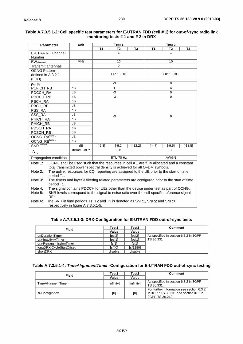
3GPP
230Release 8 3GPP TS 36.133 V8.9.0 (2010-03)
Table A.7.3.5.1-2: Cell specific test parameters for E-UTRAN FDD (cell # 1) for out-of-sync radio link monitoring tests # 1 and # 2 in DRX
Parameter Unit Test 1 Test 2 T1 T2 T3 T1 T2 T3
E-UTRA RF Channel Number
1 1
BWchannel MHz 10 10 Transmit antennas 2 1 OCNG Pattern defined in A.3.2.1 (FDD)
OP.1 FDD
OP.1 FDD
rA, rB -3 0 PCFICH_RB dB 1 4 PDCCH_RA dB -3 0 PDCCH_RB dB -3 0 PBCH_RA dB
-3
0
PBCH_RB dB PSS_RA dB SSS_RA dB PHICH_RA dB PHICH_RB dB PDSCH_RA dB PDSCH_RB dB OCNG_RANote1 dB OCNG_RBNote1 dB SNR Note 6 dB [-2.3] [-6.2] [-12.2] [-4.7] [-9.5] [-13.5]
ocN dBm/15 kHz -98 -98
Propagation condition ETU 70 Hz AWGN
Note 1: OCNG shall be used such that the resources in cell # 1 are fully allocated and a constant total transmitted power spectral density is achieved for all OFDM symbols.
Note 2: The uplink resources for CQI reporting are assigned to the UE prior to the start of time period T1.
Note 3: The timers and layer 3 filtering related parameters are configured prior to the start of time period T1.
Note 4: The signal contains PDCCH for UEs other than the device under test as part of OCNG. Note 5: SNR levels correspond to the signal to noise ratio over the cell-specific reference signal
REs. Note 6: The SNR in time periods T1, T2 and T3 is denoted as SNR1, SNR2 and SNR3
respectively in figure A.7.3.5.1-5.
Table A.7.3.5.1-3: DRX-Configuration for E-UTRAN FDD out-of-sync tests
Field Test1 Test2 Comment Value Value
onDurationTimer [psf2] [psf2] As specified in section 6.3.2 in 3GPP TS 36.331 drx-InactivityTimer [psf1] [psf1]
drx-RetransmissionTimer [sf1] [sf1] longDRX-CycleStartOffset [sf40] [sf1280] shortDRX disable disable
Table A.7.3.5.1-4: TimeAlignmentTimer -Configuration for E-UTRAN FDD out-of-sync testing
Field Test1 Test2 Comment Value Value
TimeAlignmentTimer [infinity] [infinity] As specified in section 6.3.2 in 3GPP TS 36.331
sr-ConfigIndex [0] [0] For further information see section 6.3.2 in 3GPP TS 36.331 and section10.1 in 3GPP TS 36.213.
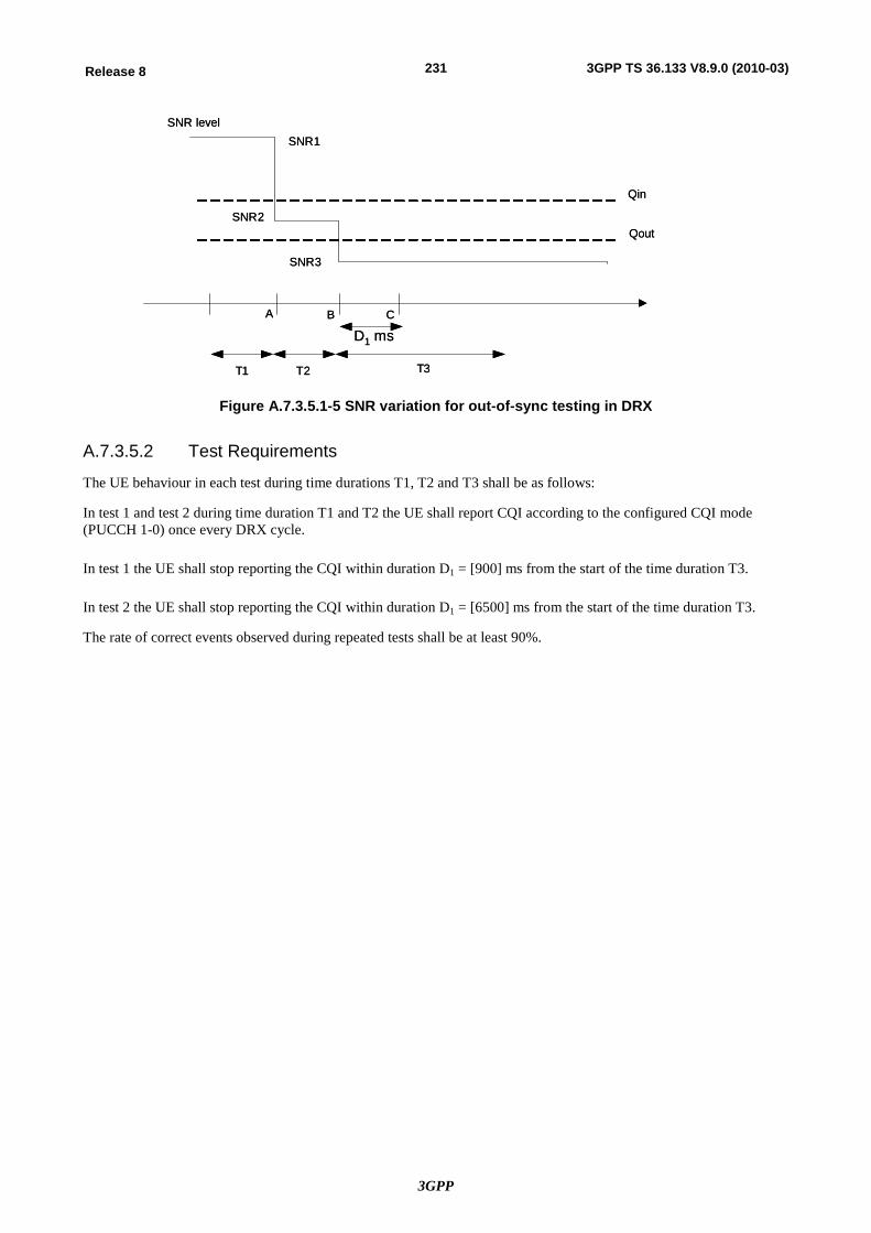
3GPP
231Release 8 3GPP TS 36.133 V8.9.0 (2010-03)
Qin
Qout
SNR level
A B
T1 T2 T3
C
SNR1
SNR2
SNR3
D1 ms
Qin
Qout
SNR level
A B
T1 T2 T3
C
SNR1
SNR2
SNR3
D1 ms
Figure A.7.3.5.1-5 SNR variation for out-of-sync testing in DRX
A.7.3.5.2 Test Requirements
The UE behaviour in each test during time durations T1, T2 and T3 shall be as follows:
In test 1 and test 2 during time duration T1 and T2 the UE shall report CQI according to the configured CQI mode (PUCCH 1-0) once every DRX cycle.
In test 1 the UE shall stop reporting the CQI within duration D1 = [900] ms from the start of the time duration T3.
In test 2 the UE shall stop reporting the CQI within duration D1 = [6500] ms from the start of the time duration T3.
The rate of correct events observed during repeated tests shall be at least 90%.
3GPP
232Release 8 3GPP TS 36.133 V8.9.0 (2010-03)
A.7.3.6 E-UTRAN FDD Radio Link Monitoring Test for In-sync in DRX
A.7.3.6.1 Test Purpose and Environment
The purpose of this test is to verify that the UE properly detects the out of sync and in sync for the purpose of monitoring downlink radio link quality of the serving cell when DRX is used. This test will partly verify the E-UTRAN FDD radio link monitoring requirements in section 7.6.
The test parameters are given in Tables A.7.3.6.1-1, A.7.3.6.1-2, A.7.3.6.1-3 and A.7.3.6.1-4. There is one cell (cell 1), which is the active cell, in the test. The test consists of five successive time periods, with time duration of T1, T2, T3, T4 and T5 respectively. Figure A.7.3.6.1-5 shows the variation of the downlink SNR in the active cell to emulate out-of-sync and in-sync states. Prior to the start of the time duration T1, the UE shall be fully synchronized to cell 1. The UE shall be configured for periodic CQI reporting in PUCCH 1-0 mode with a reporting periodicity of 2 ms. In the test, DRX configuration is enabled and DRX inactivity timer has already been expired, i.e. UE tries to decode PDCCH and to send periodic CQI during the period when On-duration timer is running. Time alignment timers shall be set to “infinity” so that UL timing alignment is maintained during the test.
Table A.7.3.6.1-1: General test parameters for E-UTRAN FDD in-sync test in DRX
Parameter Unit Value Comment
PDSCH parameters R.0 FDD As specified in section A.3.1.1.1. PCFICH/PDCCH/PHICH parameters R.6 FDD As specified in section A.3.1.2.1. Active cell Cell 1 Cell 1 is on E-UTRA RF channel
number 1 CP length Normal E-UTRA RF Channel Number 1 One E-UTRA FDD carrier
frequency is used. E-UTRA Channel Bandwidth (BWchannel) MHz 10 Transmit antennas 1 In sync transmission parameters (Note 1)
DCI format 1C As defined in section 5.3.3.1.4 in TS 36.212
Number of Control OFDM symbols
2 In sync threshold Qin and the corresponding hypothetical PDCCH/PCFICH transmission parameters are as specified in section and Table 7.6.1-2 respectively.
Aggregation level CCE 4 rA, rB 0 Ratio of PDCCH to RS EPRE
0
Ratio of PCFICH to RS EPRE
4
Out of sync transmission parameters (Note 1)
DCI format 1A As defined in section 5.3.3.1.3 in TS 36.212
Number of Control OFDM symbols
2 Out of sync threshold Qout and the corresponding hypothetical PDCCH/PCFICH transmission parameters are as specified in section 7.6.1 and Table 7.6.1-1 respectively.
Aggregation level CCE 8 rA, rB 0
Ratio of PDCCH to RS EPRE
dB 4
Ratio of PCFICH to RS EPRE
dB 4
DRX cycle ms 40 See Table A.7.3.6.1-3 Layer 3 filtering Enabled Counters:
N310 = 1; N311 = 1 T310 timer ms [2000] T310 is enabled T311 timer ms 1000 T311 is enabled Periodic CQI reporting mode PUCCH 1-0 As defined in table 7.2.2-1 in TS
36.213. CQI reporting periodicity ms 2 Minimum CQI reporting periodicity Propagation channel AWGN T1 s [4] T2 s [1.6] T3 s [1.46] T4 s [0.4] T5 s [4] Note 1: PDCCH/PCFICH corresponding to the in-sync and out of sync transmission
parameters need not be included in the Reference Measurement Channel.
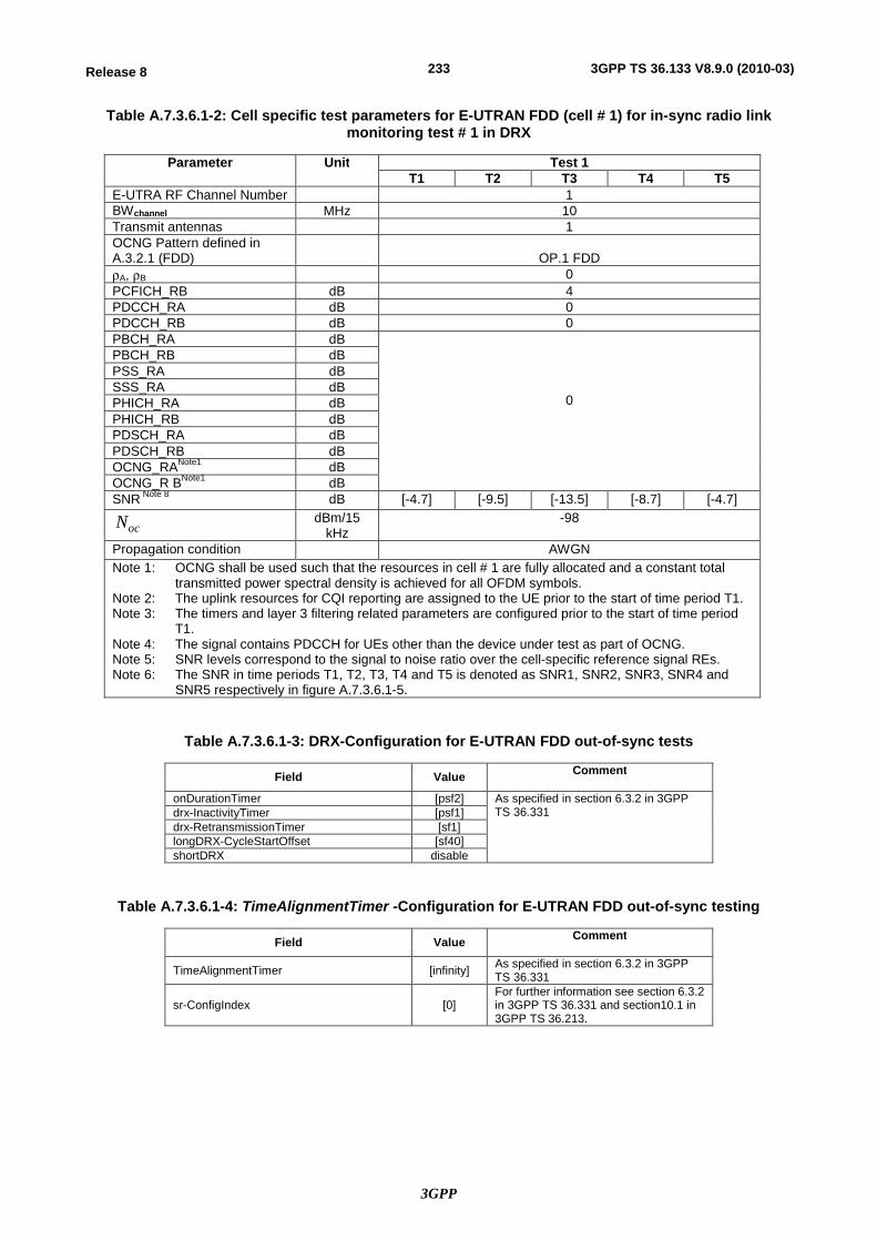
3GPP
233Release 8 3GPP TS 36.133 V8.9.0 (2010-03)
Table A.7.3.6.1-2: Cell specific test parameters for E-UTRAN FDD (cell # 1) for in-sync radio link monitoring test # 1 in DRX
Parameter Unit Test 1 T1 T2 T3 T4 T5
E-UTRA RF Channel Number 1 BWchannel MHz 10 Transmit antennas 1 OCNG Pattern defined in A.3.2.1 (FDD)
OP.1 FDD
rA, rB 0 PCFICH_RB dB 4 PDCCH_RA dB 0 PDCCH_RB dB 0 PBCH_RA dB
0
PBCH_RB dB PSS_RA dB SSS_RA dB PHICH_RA dB PHICH_RB dB PDSCH_RA dB PDSCH_RB dB OCNG_RANote1 dB OCNG_R BNote1 dB SNR Note 8 dB [-4.7] [-9.5] [-13.5] [-8.7] [-4.7]
ocN dBm/15 kHz
-98
Propagation condition AWGN Note 1: OCNG shall be used such that the resources in cell # 1 are fully allocated and a constant total
transmitted power spectral density is achieved for all OFDM symbols. Note 2: The uplink resources for CQI reporting are assigned to the UE prior to the start of time period T1. Note 3: The timers and layer 3 filtering related parameters are configured prior to the start of time period
T1. Note 4: The signal contains PDCCH for UEs other than the device under test as part of OCNG. Note 5: SNR levels correspond to the signal to noise ratio over the cell-specific reference signal REs. Note 6: The SNR in time periods T1, T2, T3, T4 and T5 is denoted as SNR1, SNR2, SNR3, SNR4 and
SNR5 respectively in figure A.7.3.6.1-5.
Table A.7.3.6.1-3: DRX-Configuration for E-UTRAN FDD out-of-sync tests
Field Value Comment
onDurationTimer [psf2] As specified in section 6.3.2 in 3GPP TS 36.331 drx-InactivityTimer [psf1]
drx-RetransmissionTimer [sf1] longDRX-CycleStartOffset [sf40] shortDRX disable
Table A.7.3.6.1-4: TimeAlignmentTimer -Configuration for E-UTRAN FDD out-of-sync testing
Field Value Comment
TimeAlignmentTimer [infinity] As specified in section 6.3.2 in 3GPP TS 36.331
sr-ConfigIndex [0] For further information see section 6.3.2 in 3GPP TS 36.331 and section10.1 in 3GPP TS 36.213.
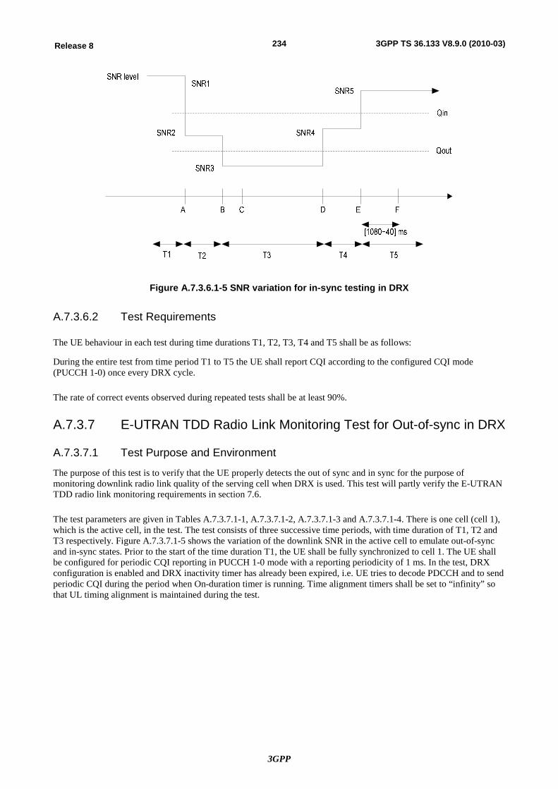
3GPP
234Release 8 3GPP TS 36.133 V8.9.0 (2010-03)
Figure A.7.3.6.1-5 SNR variation for in-sync testing in DRX
A.7.3.6.2 Test Requirements
The UE behaviour in each test during time durations T1, T2, T3, T4 and T5 shall be as follows:
During the entire test from time period T1 to T5 the UE shall report CQI according to the configured CQI mode (PUCCH 1-0) once every DRX cycle.
The rate of correct events observed during repeated tests shall be at least 90%.
A.7.3.7 E-UTRAN TDD Radio Link Monitoring Test for Out-of-sync in DRX
A.7.3.7.1 Test Purpose and Environment
The purpose of this test is to verify that the UE properly detects the out of sync and in sync for the purpose of monitoring downlink radio link quality of the serving cell when DRX is used. This test will partly verify the E-UTRAN TDD radio link monitoring requirements in section 7.6.
The test parameters are given in Tables A.7.3.7.1-1, A.7.3.7.1-2, A.7.3.7.1-3 and A.7.3.7.1-4. There is one cell (cell 1), which is the active cell, in the test. The test consists of three successive time periods, with time duration of T1, T2 and T3 respectively. Figure A.7.3.7.1-5 shows the variation of the downlink SNR in the active cell to emulate out-of-sync and in-sync states. Prior to the start of the time duration T1, the UE shall be fully synchronized to cell 1. The UE shall be configured for periodic CQI reporting in PUCCH 1-0 mode with a reporting periodicity of 1 ms. In the test, DRX configuration is enabled and DRX inactivity timer has already been expired, i.e. UE tries to decode PDCCH and to send periodic CQI during the period when On-duration timer is running. Time alignment timers shall be set to “infinity” so that UL timing alignment is maintained during the test.
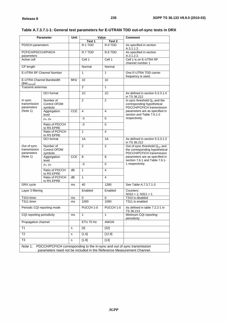
3GPP
235Release 8 3GPP TS 36.133 V8.9.0 (2010-03)
Table A.7.3.7.1-1: General test parameters for E-UTRAN TDD out-of-sync tests in DRX
Parameter Unit Value Comment Test 1 Test 2
PDSCH parameters R.1 TDD R.0 TDD As specified in section A.3.1.1.2.
PCFICH/PDCCH/PHICH parameters
R.7 TDD R.6 TDD As specified in section A.3.1.2.2.
Active cell Cell 1 Cell 1 Cell 1 is on E-UTRA RF channel number 1
CP length Normal Normal
E-UTRA RF Channel Number 1 1 One E-UTRA TDD carrier frequency is used.
E-UTRA Channel Bandwidth (BWchannel)
MHz 10 10
Transmit antennas 2 1
In sync transmission parameters (Note 1)
DCI format 1C 1C As defined in section 5.3.3.1.4 in TS 36.212
Number of Control OFDM symbols
2 2 In sync threshold Qin and the corresponding hypothetical PDCCH/PCFICH transmission parameters are as specified in section and Table 7.6.1-2 respectively.
Aggregation level
CCE 4 4
rA, rB -3 0
Ratio of PDCCH to RS EPRE
-3 0
Ratio of PCFICH to RS EPRE
1 4
Out of sync transmission parameters (Note 1)
DCI format 1A 1A As defined in section 5.3.3.1.3 in TS 36.212
Number of Control OFDM symbols
2 2 Out of sync threshold Qout and the corresponding hypothetical PDCCH/PCFICH transmission parameters are as specified in section 7.6.1 and Table 7.6.1-1 respectively.
Aggregation level
CCE 8 8
rA, rB -3 0
Ratio of PDCCH to RS EPRE
dB 1 4
Ratio of PCFICH to RS EPRE
dB 1 4
DRX cycle ms 40 1280 See Table A.7.3.7.1-3
Layer 3 filtering Enabled Enabled Counters: N310 = 1; N311 = 1
T310 timer ms 0 0 T310 is disabled T311 timer ms 1000 1000 T311 is enabled
Periodic CQI reporting mode PUCCH 1-0 PUCCH 1-0 As defined in table 7.2.2-1 in TS 36.213.
CQI reporting periodicity ms 1 1 Minimum CQI reporting periodicity
Propagation channel ETU 70 Hz AWGN .
T1 s [4] [32]
T2 s [1.6] [12.8]
T3 s [1.8] [13]
Note 1: PDCCH/PCFICH corresponding to the in-sync and out of sync transmission parameters need not be included in the Reference Measurement Channel.
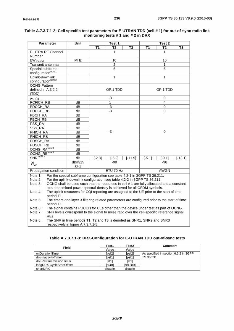
3GPP
236Release 8 3GPP TS 36.133 V8.9.0 (2010-03)
Table A.7.3.7.1-2: Cell specific test parameters for E-UTRAN TDD (cell # 1) for out-of-sync radio link monitoring tests # 1 and # 2 in DRX
Parameter Unit Test 1 Test 2 T1 T2 T3 T1 T2 T3
E-UTRA RF Channel Number
1 1
BWchannel MHz 10 10 Transmit antennas 2 1 Special subframe configurationNote1
6 6
Uplink-downlink configurationNote2
1 1
OCNG Pattern defined in A.3.2.2 (TDD)
OP.1 TDD
OP.1 TDD
rA, rB -3 0 PCFICH_RB dB 1 4 PDCCH_RA dB -3 0 PDCCH_RB dB -3 0 PBCH_RA dB
-3
0
PBCH_RB dB PSS_RA dB SSS_RA dB PHICH_RA dB PHICH_RB dB PDSCH_RA dB PDSCH_RB dB OCNG_RANote3 dB OCNG_RBNote3 dB SNR Note 8 dB [-2.3] [-5.9] [-11.9] [-5.1] [-9.1] [-13.1]
ocN dBm/15 kHz
-98 -98
Propagation condition ETU 70 Hz AWGN Note 1: For the special subframe configuration see table 4.2-1 in 3GPP TS 36.211. Note 2: For the uplink-downlink configuration see table 4.2-2 in 3GPP TS 36.211. Note 3: OCNG shall be used such that the resources in cell # 1 are fully allocated and a constant
total transmitted power spectral density is achieved for all OFDM symbols. Note 4: The uplink resources for CQI reporting are assigned to the UE prior to the start of time
period T1. Note 5: The timers and layer 3 filtering related parameters are configured prior to the start of time
period T1. Note 6: The signal contains PDCCH for UEs other than the device under test as part of OCNG. Note 7: SNR levels correspond to the signal to noise ratio over the cell-specific reference signal
REs. Note 8: The SNR in time periods T1, T2 and T3 is denoted as SNR1, SNR2 and SNR3
respectively in figure A.7.3.7.1-5.
Table A.7.3.7.1-3: DRX-Configuration for E-UTRAN TDD out-of-sync tests
Field Test1 Test2 Comment Value Value
onDurationTimer [psf2] [psf2] As specified in section 6.3.2 in 3GPP TS 36.331 drx-InactivityTimer [psf1] [psf1]
drx-RetransmissionTimer [sf1] [sf1] longDRX-CycleStartOffset [sf40] [sf1280] shortDRX disable disable
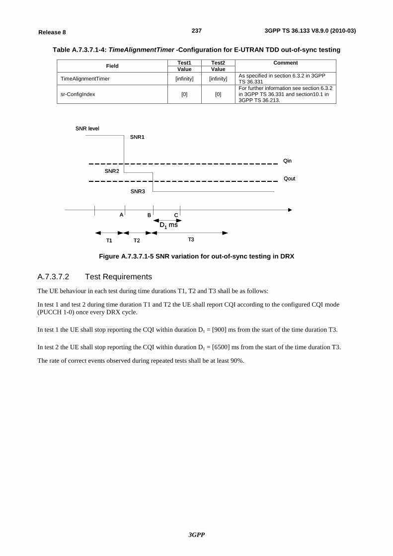
3GPP
237Release 8 3GPP TS 36.133 V8.9.0 (2010-03)
Table A.7.3.7.1-4: TimeAlignmentTimer -Configuration for E-UTRAN TDD out-of-sync testing
Field Test1 Test2 Comment Value Value
TimeAlignmentTimer [infinity] [infinity] As specified in section 6.3.2 in 3GPP TS 36.331
sr-ConfigIndex [0] [0] For further information see section 6.3.2 in 3GPP TS 36.331 and section10.1 in 3GPP TS 36.213.
Qin
Qout
SNR level
A B
T1 T2 T3
C
SNR1
SNR2
SNR3
D1 ms
Qin
Qout
SNR level
A B
T1 T2 T3
C
SNR1
SNR2
SNR3
D1 ms
Figure A.7.3.7.1-5 SNR variation for out-of-sync testing in DRX
A.7.3.7.2 Test Requirements
The UE behaviour in each test during time durations T1, T2 and T3 shall be as follows:
In test 1 and test 2 during time duration T1 and T2 the UE shall report CQI according to the configured CQI mode (PUCCH 1-0) once every DRX cycle.
In test 1 the UE shall stop reporting the CQI within duration D1 = [900] ms from the start of the time duration T3.
In test 2 the UE shall stop reporting the CQI within duration D1 = [6500] ms from the start of the time duration T3.
The rate of correct events observed during repeated tests shall be at least 90%.

3GPP
238Release 8 3GPP TS 36.133 V8.9.0 (2010-03)
A.7.3.8 E-UTRAN TDD Radio Link Monitoring Test for In-sync in DRX
A.7.3.8.1 Test Purpose and Environment
The purpose of this test is to verify that the UE properly detects the out of sync and in sync for the purpose of monitoring downlink radio link quality of the serving cell when DRX is used. This test will partly verify the E-UTRAN TDD radio link monitoring requirements in section 7.6.
The test parameters are given in Tables A.7.3.8.1-1, A.7.3.8.1-2, A.7.3.8.1-3 and A.7.3.8.1-4. There is one cell (cell 1), which is the active cell, in the test. The test consists of five successive time periods, with time duration of T1, T2, T3, T4 and T5 respectively. Figure A.7.3.8.1-5 shows the variation of the downlink SNR in the active cell to emulate out-of-sync and in-sync states. Prior to the start of the time duration T1, the UE shall be fully synchronized to cell 1. The UE shall be configured for periodic CQI reporting in PUCCH 1-0 mode with a reporting periodicity of 1 ms. In the test, DRX configuration is enabled and DRX inactivity timer has already been expired, i.e. UE tries to decode PDCCH and to send periodic CQI during the period when On-duration timer is running. Time alignment timers shall be set to “infinity” so that UL timing alignment is maintained during the test.
Table A.7.3.8.1-1: General test parameters for E-UTRAN TDD in-sync test in DRX
Parameter Unit Value Comment
PDSCH parameters R.0 TDD As specified in section A.3.1.1.2. PCFICH/PDCCH/PHICH parameters R.6 TDD As specified in section A.3.1.2.2. Active cell Cell 1 Cell 1 is on E-UTRA RF channel
number 1 CP length Normal E-UTRA RF Channel Number 1 One E-UTRA TDD carrier
frequency is used. E-UTRA Channel Bandwidth (BWchannel) MHz 10 Transmit antennas 1 In sync transmission parameters (Note 1)
DCI format 1C As defined in section 5.3.3.1.4 in TS 36.212
Number of Control OFDM symbols
2 In sync threshold Qin and the corresponding hypothetical PDCCH/PCFICH transmission parameters are as specified in section and Table 7.6.1-2 respectively.
Aggregation level CCE 4 rA, rB 0 Ratio of PDCCH to RS EPRE
0
Ratio of PCFICH to RS EPRE
4
Out of sync transmission parameters (Note 1)
DCI format 1A As defined in section 5.3.3.1.3 in TS 36.212
Number of Control OFDM symbols
2 Out of sync threshold Qout and the corresponding hypothetical PDCCH/PCFICH transmission parameters are as specified in section 7.6.1 and Table 7.6.1-1 respectively.
Aggregation level CCE 8 rA, rB 0
Ratio of PDCCH to RS EPRE
dB 4
Ratio of PCFICH to RS EPRE
dB 4
DRX cycle ms 40 See Table A.7.3.8.1-3 Layer 3 filtering Enabled Counters:
N310 = 1; N311 = 1 T310 timer ms [2000] T310 is enabled T311 timer ms 1000 T311 is enabled Periodic CQI reporting mode PUCCH 1-0 As defined in table 7.2.2-1 in TS
36.213. CQI reporting periodicity ms 1 Minimum CQI reporting periodicity Propagation channel AWGN T1 s [4] T2 s [1.6] T3 s [1.46] T4 s [0.4] T5 s [4] Note 1: PDCCH/PCFICH corresponding to the in-sync and out of sync transmission
parameters need not be included in the Reference Measurement Channel.
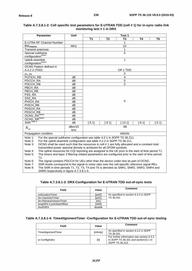
3GPP
239Release 8 3GPP TS 36.133 V8.9.0 (2010-03)
Table A.7.3.8.1-2: Cell specific test parameters for E-UTRAN TDD (cell # 1) for in-sync radio link monitoring test # 1 in DRX
Parameter Unit Test 1 T1 T2 T3 T4 T5
E-UTRA RF Channel Number 1 BWchannel MHz 10 Transmit antennas 1 Special subframe configurationNote1
6
Uplink-downlink configurationNote2 1
OCNG Pattern defined in A.3.2.2 (TDD)
OP.1 TDD
rA, rB 0 PCFICH_RB dB 4 PDCCH_RA dB 0 PDCCH_RB dB 0 PBCH_RA dB
0
PBCH_RB dB PSS_RA dB SSS_RA dB PHICH_RA dB PHICH_RB dB PDSCH_RA dB PDSCH_RB dB OCNG_RANote3 dB OCNG_RBNote3 dB SNR Note 8 dB [-5.1] [-9.1] [-13.1] [-9.1] [-5.1]
ocN dBm/15 kHz
-98
Propagation condition AWGN Note 1: For the special subframe configuration see table 4.2-1 in 3GPP TS 36.211. Note 2: For the uplink-downlink configuration see table 4.2-2 in 3GPP TS 36.211. Note 3: OCNG shall be used such that the resources in cell # 1 are fully allocated and a constant total
transmitted power spectral density is achieved for all OFDM symbols. Note 4: The uplink resources for CQI reporting are assigned to the UE prior to the start of time period T1. Note 5: The timers and layer 3 filtering related parameters are configured prior to the start of time period
T1. Note 6: The signal contains PDCCH for UEs other than the device under test as part of OCNG. Note 7: SNR levels correspond to the signal to noise ratio over the cell-specific reference signal REs. Note 8: The SNR in time periods T1, T2, T3, T4 and T5 is denoted as SNR1, SNR2, SNR3, SNR4 and
SNR5 respectively in figure A.7.3.8.1-5.
Table A.7.3.8.1-3: DRX-Configuration for E-UTRAN TDD out-of-sync tests
Field Value Comment
onDurationTimer [psf2] As specified in section 6.3.2 in 3GPP TS 36.331 drx-InactivityTimer [psf1]
drx-RetransmissionTimer [sf1] longDRX-CycleStartOffset [sf40] shortDRX disable
Table A.7.3.8.1-4: TimeAlignmentTimer -Configuration for E-UTRAN TDD out-of-sync testing
Field Value Comment
TimeAlignmentTimer [infinity] As specified in section 6.3.2 in 3GPP TS 36.331
sr-ConfigIndex [0] For further information see section 6.3.2 in 3GPP TS 36.331 and section10.1 in 3GPP TS 36.213.
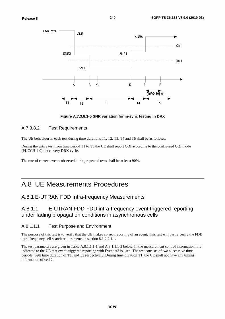
3GPP
240Release 8 3GPP TS 36.133 V8.9.0 (2010-03)
Figure A.7.3.8.1-5 SNR variation for in-sync testing in DRX
A.7.3.8.2 Test Requirements
The UE behaviour in each test during time durations T1, T2, T3, T4 and T5 shall be as follows:
During the entire test from time period T1 to T5 the UE shall report CQI according to the configured CQI mode (PUCCH 1-0) once every DRX cycle.
The rate of correct events observed during repeated tests shall be at least 90%.
A.8 UE Measurements Procedures
A.8.1 E-UTRAN FDD Intra-frequency Measurements
A.8.1.1 E-UTRAN FDD-FDD intra-frequency event triggered reporting under fading propagation conditions in asynchronous cells
A.8.1.1.1 Test Purpose and Environment
The purpose of this test is to verify that the UE makes correct reporting of an event. This test will partly verify the FDD intra-frequency cell search requirements in section 8.1.2.2.1.1.
The test parameters are given in Table A.8.1.1.1-1 and A.8.1.1.1-2 below. In the measurement control information it is indicated to the UE that event-triggered reporting with Event A3 is used. The test consists of two successive time periods, with time duration of T1, and T2 respectively. During time duration T1, the UE shall not have any timing information of cell 2.
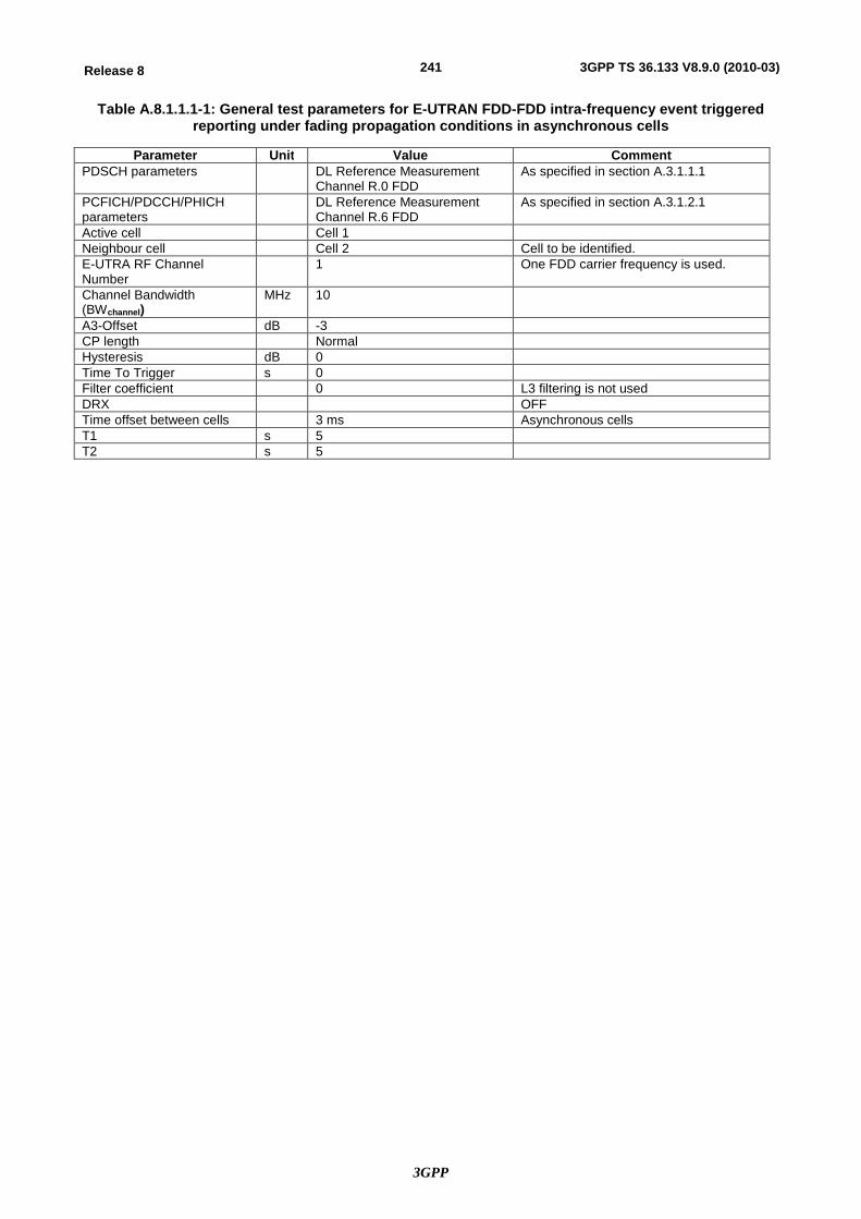
3GPP
241Release 8 3GPP TS 36.133 V8.9.0 (2010-03)
Table A.8.1.1.1-1: General test parameters for E-UTRAN FDD-FDD intra-frequency event triggered reporting under fading propagation conditions in asynchronous cells
Parameter Unit Value Comment PDSCH parameters DL Reference Measurement
Channel R.0 FDD As specified in section A.3.1.1.1
PCFICH/PDCCH/PHICH parameters
DL Reference Measurement Channel R.6 FDD
As specified in section A.3.1.2.1
Active cell Cell 1 Neighbour cell Cell 2 Cell to be identified. E-UTRA RF Channel Number
1 One FDD carrier frequency is used.
Channel Bandwidth (BWchannel)
MHz 10
A3-Offset dB -3 CP length Normal Hysteresis dB 0 Time To Trigger s 0 Filter coefficient 0 L3 filtering is not used DRX OFF Time offset between cells 3 ms Asynchronous cells T1 s 5 T2 s 5
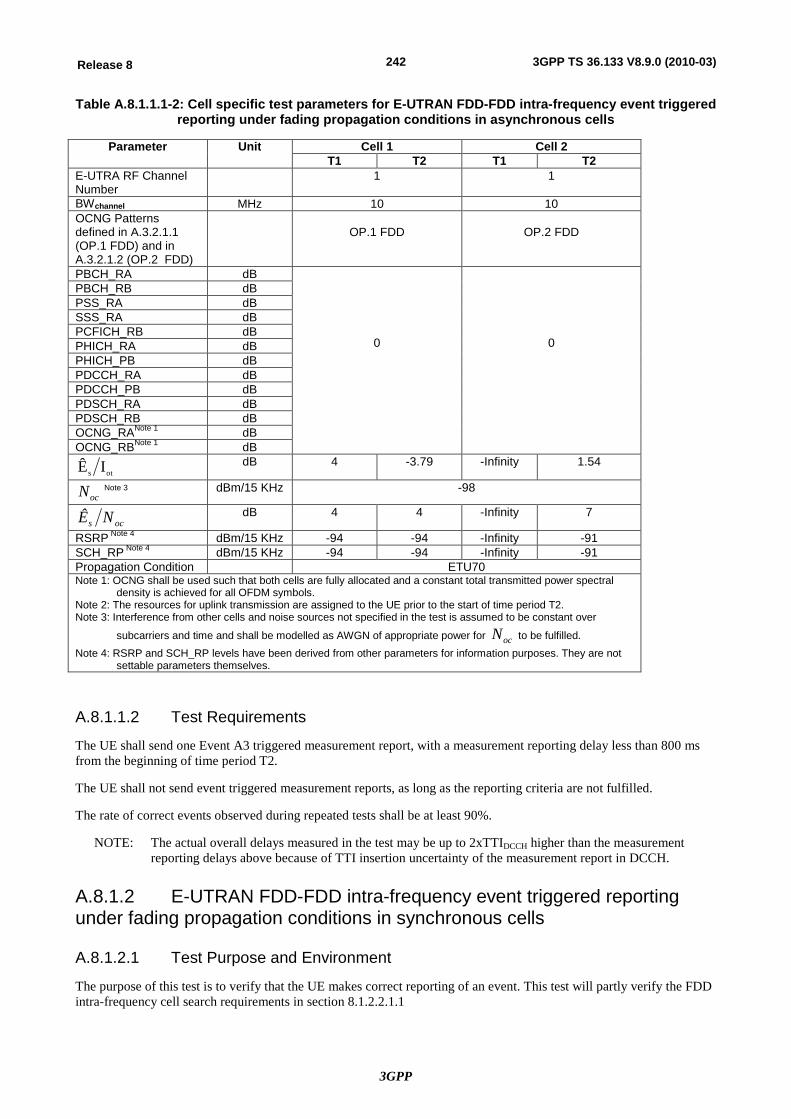
3GPP
242Release 8 3GPP TS 36.133 V8.9.0 (2010-03)
Table A.8.1.1.1-2: Cell specific test parameters for E-UTRAN FDD-FDD intra-frequency event triggered reporting under fading propagation conditions in asynchronous cells
Parameter Unit Cell 1 Cell 2 T1 T2 T1 T2
E-UTRA RF Channel Number
1 1
BWchannel MHz 10 10 OCNG Patterns defined in A.3.2.1.1 (OP.1 FDD) and in A.3.2.1.2 (OP.2 FDD)
OP.1 FDD
OP.2 FDD
PBCH_RA dB
0
0
PBCH_RB dB PSS_RA dB SSS_RA dB PCFICH_RB dB PHICH_RA dB PHICH_PB dB PDCCH_RA dB PDCCH_PB dB PDSCH_RA dB PDSCH_RB dB OCNG_RANote 1 dB OCNG_RBNote 1 dB
ots IÊ dB 4 -3.79 -Infinity 1.54
ocN Note 3 dBm/15 KHz -98
ocs NÊ dB 4 4 -Infinity 7
RSRP Note 4 dBm/15 KHz -94 -94 -Infinity -91 SCH_RP Note 4 dBm/15 KHz -94 -94 -Infinity -91 Propagation Condition ETU70 Note 1: OCNG shall be used such that both cells are fully allocated and a constant total transmitted power spectral
density is achieved for all OFDM symbols. Note 2: The resources for uplink transmission are assigned to the UE prior to the start of time period T2. Note 3: Interference from other cells and noise sources not specified in the test is assumed to be constant over
subcarriers and time and shall be modelled as AWGN of appropriate power for ocN to be fulfilled. Note 4: RSRP and SCH_RP levels have been derived from other parameters for information purposes. They are not
settable parameters themselves.
A.8.1.1.2 Test Requirements
The UE shall send one Event A3 triggered measurement report, with a measurement reporting delay less than 800 ms from the beginning of time period T2.
The UE shall not send event triggered measurement reports, as long as the reporting criteria are not fulfilled.
The rate of correct events observed during repeated tests shall be at least 90%.
NOTE: The actual overall delays measured in the test may be up to 2xTTIDCCH higher than the measurement reporting delays above because of TTI insertion uncertainty of the measurement report in DCCH.
A.8.1.2 E-UTRAN FDD-FDD intra-frequency event triggered reporting under fading propagation conditions in synchronous cells
A.8.1.2.1 Test Purpose and Environment
The purpose of this test is to verify that the UE makes correct reporting of an event. This test will partly verify the FDD intra-frequency cell search requirements in section 8.1.2.2.1.1
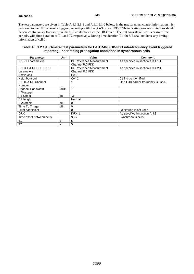
3GPP
243Release 8 3GPP TS 36.133 V8.9.0 (2010-03)
The test parameters are given in Table A.8.1.2.1-1 and A.8.1.2.1-2 below. In the measurement control information it is indicated to the UE that event-triggered reporting with Event A3 is used. PDCCHs indicating new transmissions should be sent continuously to ensure that the UE would not enter the DRX state. The test consists of two successive time periods, with time duration of T1, and T2 respectively. During time duration T1, the UE shall not have any timing information of cell 2.
Table A.8.1.2.1-1: General test parameters for E-UTRAN FDD-FDD intra-frequency event triggered reporting under fading propagation conditions in synchronous cells
Parameter Unit Value Comment PDSCH parameters DL Reference Measurement
Channel R.0 FDD As specified in section A.3.1.1.1
PCFICH/PDCCH/PHICH parameters
DL Reference Measurement Channel R.6 FDD
As specified in section A.3.1.2.1
Active cell Cell 1 Neighbour cell Cell 2 Cell to be identified. E-UTRA RF Channel Number
1 One FDD carrier frequency is used.
Channel Bandwidth (BWchannel)
MHz 10
A3-Offset dB -3 CP length Normal Hysteresis dB 0 Time To Trigger dB 0 Filter coefficient 0 L3 filtering is not used DRX DRX_L As specified in section A.3.3 Time offset between cells 3 ms Synchronous cells T1 s 5 T2 s 5
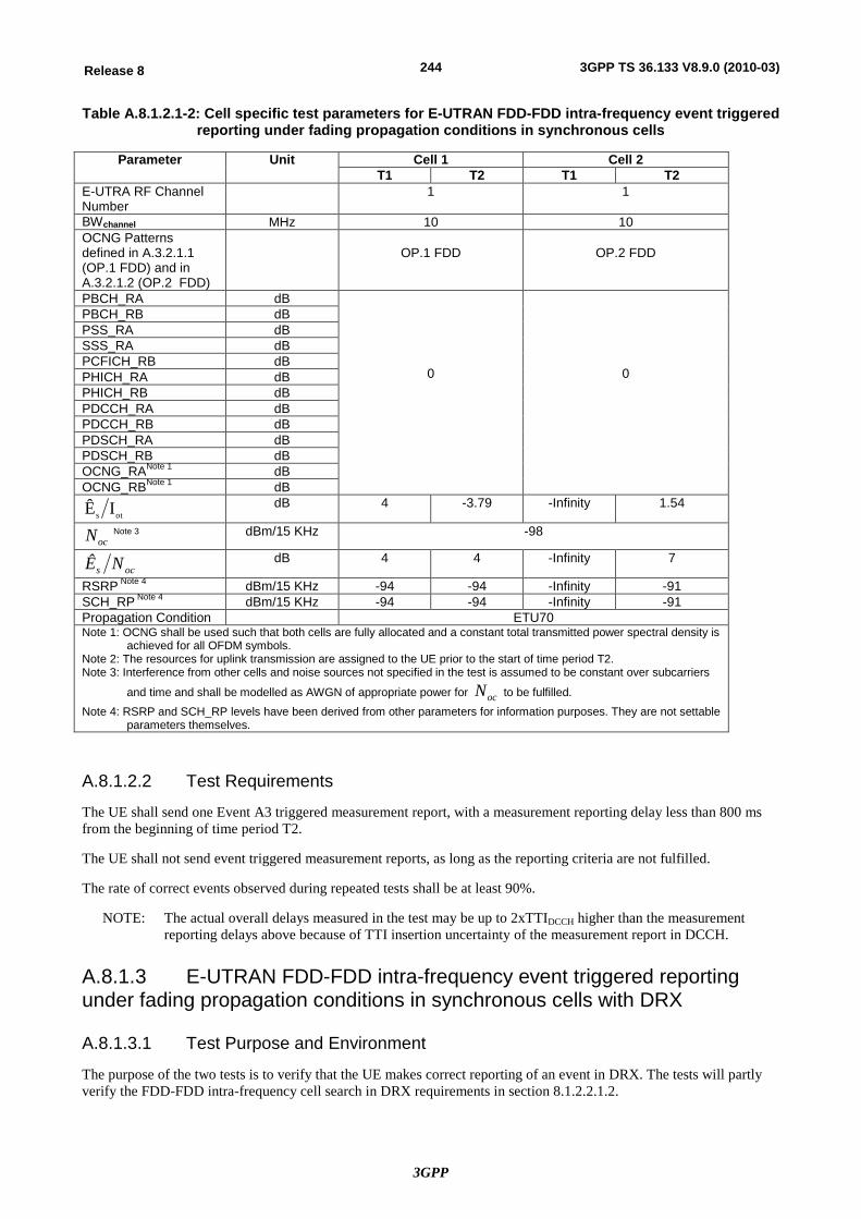
3GPP
244Release 8 3GPP TS 36.133 V8.9.0 (2010-03)
Table A.8.1.2.1-2: Cell specific test parameters for E-UTRAN FDD-FDD intra-frequency event triggered reporting under fading propagation conditions in synchronous cells
Parameter Unit Cell 1 Cell 2 T1 T2 T1 T2
E-UTRA RF Channel Number
1 1
BWchannel MHz 10 10 OCNG Patterns defined in A.3.2.1.1 (OP.1 FDD) and in A.3.2.1.2 (OP.2 FDD)
OP.1 FDD
OP.2 FDD
PBCH_RA dB
0
0
PBCH_RB dB PSS_RA dB SSS_RA dB PCFICH_RB dB PHICH_RA dB PHICH_RB dB PDCCH_RA dB PDCCH_RB dB PDSCH_RA dB PDSCH_RB dB OCNG_RANote 1 dB OCNG_RBNote 1 dB
ots IÊ dB 4 -3.79 -Infinity 1.54
ocN Note 3 dBm/15 KHz -98
ocs NÊ dB 4 4 -Infinity 7
RSRP Note 4 dBm/15 KHz -94 -94 -Infinity -91 SCH_RP Note 4 dBm/15 KHz -94 -94 -Infinity -91 Propagation Condition ETU70 Note 1: OCNG shall be used such that both cells are fully allocated and a constant total transmitted power spectral density is
achieved for all OFDM symbols. Note 2: The resources for uplink transmission are assigned to the UE prior to the start of time period T2. Note 3: Interference from other cells and noise sources not specified in the test is assumed to be constant over subcarriers
and time and shall be modelled as AWGN of appropriate power for ocN to be fulfilled. Note 4: RSRP and SCH_RP levels have been derived from other parameters for information purposes. They are not settable
parameters themselves.
A.8.1.2.2 Test Requirements
The UE shall send one Event A3 triggered measurement report, with a measurement reporting delay less than 800 ms from the beginning of time period T2.
The UE shall not send event triggered measurement reports, as long as the reporting criteria are not fulfilled.
The rate of correct events observed during repeated tests shall be at least 90%.
NOTE: The actual overall delays measured in the test may be up to 2xTTIDCCH higher than the measurement reporting delays above because of TTI insertion uncertainty of the measurement report in DCCH.
A.8.1.3 E-UTRAN FDD-FDD intra-frequency event triggered reporting under fading propagation conditions in synchronous cells with DRX
A.8.1.3.1 Test Purpose and Environment
The purpose of the two tests is to verify that the UE makes correct reporting of an event in DRX. The tests will partly verify the FDD-FDD intra-frequency cell search in DRX requirements in section 8.1.2.2.1.2.
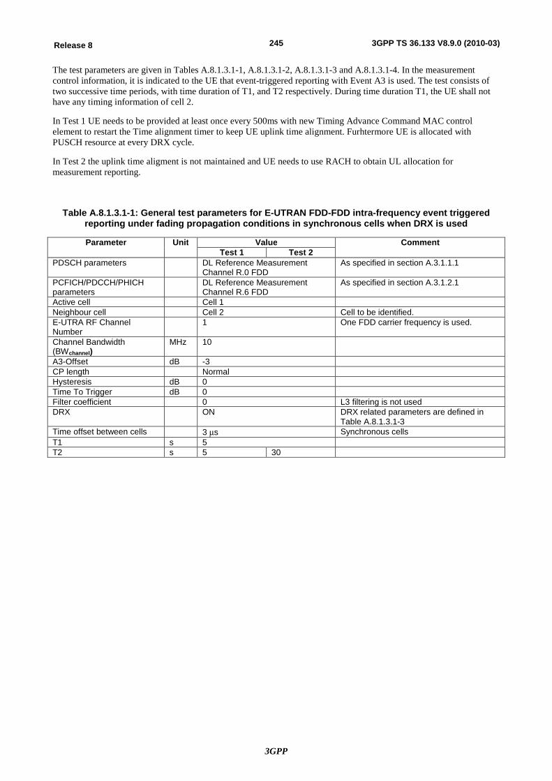
3GPP
245Release 8 3GPP TS 36.133 V8.9.0 (2010-03)
The test parameters are given in Tables A.8.1.3.1-1, A.8.1.3.1-2, A.8.1.3.1-3 and A.8.1.3.1-4. In the measurement control information, it is indicated to the UE that event-triggered reporting with Event A3 is used. The test consists of two successive time periods, with time duration of T1, and T2 respectively. During time duration T1, the UE shall not have any timing information of cell 2.
In Test 1 UE needs to be provided at least once every 500ms with new Timing Advance Command MAC control element to restart the Time alignment timer to keep UE uplink time alignment. Furhtermore UE is allocated with PUSCH resource at every DRX cycle.
In Test 2 the uplink time aligment is not maintained and UE needs to use RACH to obtain UL allocation for measurement reporting.
Table A.8.1.3.1-1: General test parameters for E-UTRAN FDD-FDD intra-frequency event triggered reporting under fading propagation conditions in synchronous cells when DRX is used
Parameter Unit Value Comment Test 1 Test 2
PDSCH parameters DL Reference Measurement Channel R.0 FDD
As specified in section A.3.1.1.1
PCFICH/PDCCH/PHICH parameters
DL Reference Measurement Channel R.6 FDD
As specified in section A.3.1.2.1
Active cell Cell 1 Neighbour cell Cell 2 Cell to be identified. E-UTRA RF Channel Number
1 One FDD carrier frequency is used.
Channel Bandwidth (BWchannel)
MHz 10
A3-Offset dB -3 CP length Normal Hysteresis dB 0 Time To Trigger dB 0 Filter coefficient 0 L3 filtering is not used DRX ON DRX related parameters are defined in
Table A.8.1.3.1-3 Time offset between cells 3 ms Synchronous cells T1 s 5 T2 s 5 30
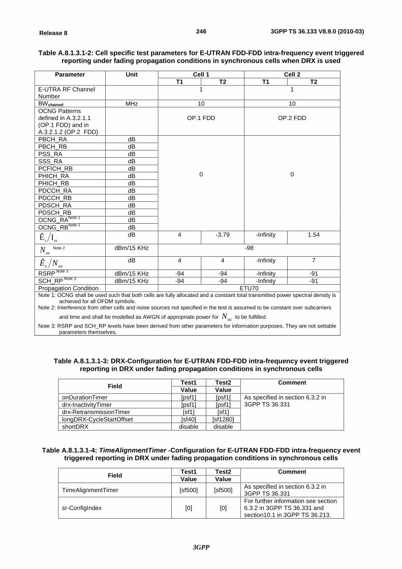
3GPP
246Release 8 3GPP TS 36.133 V8.9.0 (2010-03)
Table A.8.1.3.1-2: Cell specific test parameters for E-UTRAN FDD-FDD intra-frequency event triggered reporting under fading propagation conditions in synchronous cells when DRX is used
Parameter Unit Cell 1 Cell 2 T1 T2 T1 T2
E-UTRA RF Channel Number
1 1
BWchannel MHz 10 10 OCNG Patterns defined in A.3.2.1.1 (OP.1 FDD) and in A.3.2.1.2 (OP.2 FDD)
OP.1 FDD
OP.2 FDD
PBCH_RA dB
0
0
PBCH_RB dB PSS_RA dB SSS_RA dB PCFICH_RB dB PHICH_RA dB PHICH_RB dB PDCCH_RA dB PDCCH_RB dB PDSCH_RA dB PDSCH_RB dB OCNG_RANote 1 dB OCNG_RBNote 1 dB
ots IÊ dB 4 -3.79 -Infinity 1.54
ocN Note 2 dBm/15 KHz -98
ocs NÊ dB 4 4 -Infinity 7
RSRP Note 3 dBm/15 KHz -94 -94 -Infinity -91 SCH_RP Note 3 dBm/15 KHz -94 -94 -Infinity -91 Propagation Condition ETU70 Note 1: OCNG shall be used such that both cells are fully allocated and a constant total transmitted power spectral density is
achieved for all OFDM symbols. Note 2: Interference from other cells and noise sources not specified in the test is assumed to be constant over subcarriers
and time and shall be modelled as AWGN of appropriate power for ocN to be fulfilled. Note 3: RSRP and SCH_RP levels have been derived from other parameters for information purposes. They are not settable
parameters themselves.
Table A.8.1.3.1-3: DRX-Configuration for E-UTRAN FDD-FDD intra-frequency event triggered reporting in DRX under fading propagation conditions in synchronous cells
Field Test1 Test2 Comment Value Value
onDurationTimer [psf1] [psf1] As specified in section 6.3.2 in 3GPP TS 36.331 drx-InactivityTimer [psf1] [psf1]
drx-RetransmissionTimer [sf1] [sf1] longDRX-CycleStartOffset [sf40] [sf1280] shortDRX disable disable
Table A.8.1.3.1-4: TimeAlignmentTimer -Configuration for E-UTRAN FDD-FDD intra-frequency event triggered reporting in DRX under fading propagation conditions in synchronous cells
Field Test1 Test2 Comment Value Value
TimeAlignmentTimer [sf500] [sf500] As specified in section 6.3.2 in 3GPP TS 36.331
sr-ConfigIndex [0] [0] For further information see section 6.3.2 in 3GPP TS 36.331 and section10.1 in 3GPP TS 36.213.
3GPP
247Release 8 3GPP TS 36.133 V8.9.0 (2010-03)
A.8.1.3.2 Test Requirements
In Test 1, the UE shall send one Event A3 triggered measurement report, with a measurement reporting delay less than 800 ms from the beginning of time period T2. The measurement reporting delay is defined as the time from the beginning of time period T2 to the moment when the UE send the measurement report on PUSCH.
In Test 2, the UE shall send one Event A3 triggered measurement report, with a measurement reporting delay less than 25600 ms from the beginning of time period T2. The measurement reporting delay is defined as the time from the beginning of time period T2 to the moment when the UE starts to send preambles on the PRACH for scheduling request (SR) to obtain allocation to send the measurement report on PUSCH.
The UE shall not send event triggered measurement reports, as long as the reporting criteria are not fulfilled.
The rate of correct events observed during repeated tests shall be at least 90%.
NOTE 1: The actual overall delays measured in the test may be up to one DRX cycle higher than the measurement reporting delays above because UE is allowed to delay the initiation of the measurement reporting procedure to the next until the Active Time.
NOTE 2: In order to calculate the rate of correct events the system simulator shall verify that it has received correct Event A3 measurement report.
A.8.1.4 E-UTRAN FDD-FDD inter-frequency event triggered reporting under AWGN propagation conditions in asynchronous cells with DRX when L3 filtering is used
A.8.1.4.1 Test Purpose and Environment
The purpose of this test is to verify that the UE makes correct reporting of an event in DRX when L3 filtering is used. This test will partly verify the FDD-FDD inter-frequency cell search in DRX requirements in section 8.1.2.3.1.2 and the UE behaviour with the filterCoefficent defined in [2].
The test parameters are given in Tables A.8.1.4.1-1, A.8.1.4.1-2, A.8.1.4.1-3 and A.8.1.4.1-4. In the measurement control information, it is indicated to the UE that event-triggered reporting with Event A3 and the filter coefficient is used. The test consists of two successive time periods, with time duration of T1, and T2 respectively.
The uplink time aligment is not maintained and UE needs to use RACH to obtain UL allocation for measurement reporting.
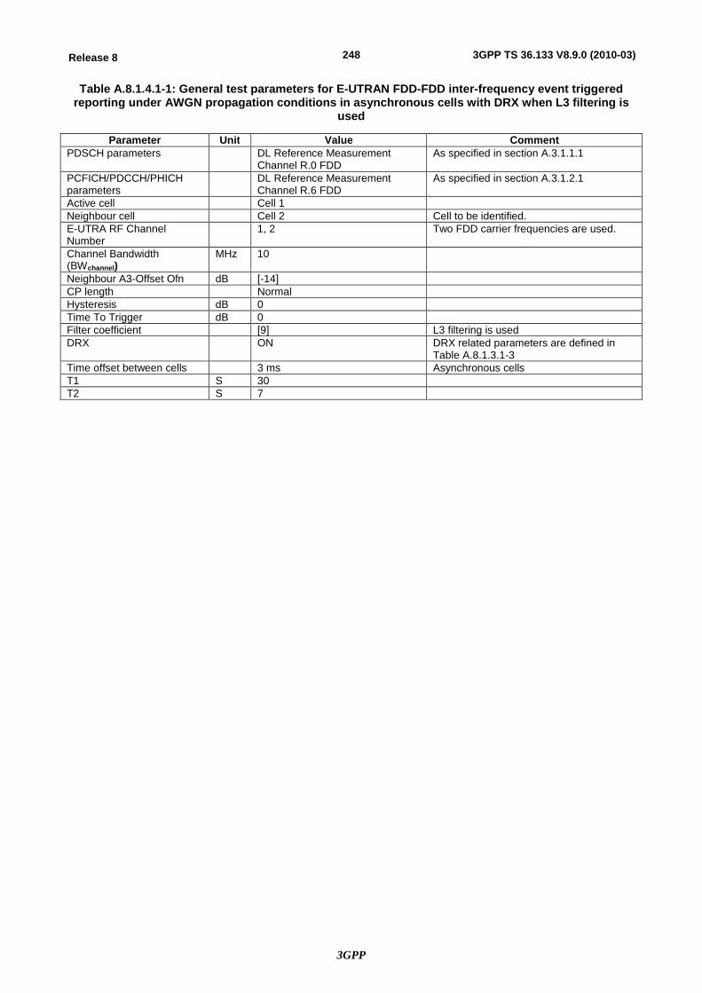
3GPP
248Release 8 3GPP TS 36.133 V8.9.0 (2010-03)
Table A.8.1.4.1-1: General test parameters for E-UTRAN FDD-FDD inter-frequency event triggered reporting under AWGN propagation conditions in asynchronous cells with DRX when L3 filtering is
used
Parameter Unit Value Comment PDSCH parameters DL Reference Measurement
Channel R.0 FDD As specified in section A.3.1.1.1
PCFICH/PDCCH/PHICH parameters
DL Reference Measurement Channel R.6 FDD
As specified in section A.3.1.2.1
Active cell Cell 1 Neighbour cell Cell 2 Cell to be identified. E-UTRA RF Channel Number
1, 2 Two FDD carrier frequencies are used.
Channel Bandwidth (BWchannel)
MHz 10
Neighbour A3-Offset Ofn dB [-14] CP length Normal Hysteresis dB 0 Time To Trigger dB 0 Filter coefficient [9] L3 filtering is used DRX ON DRX related parameters are defined in
Table A.8.1.3.1-3 Time offset between cells 3 ms Asynchronous cells T1 S 30 T2 S 7
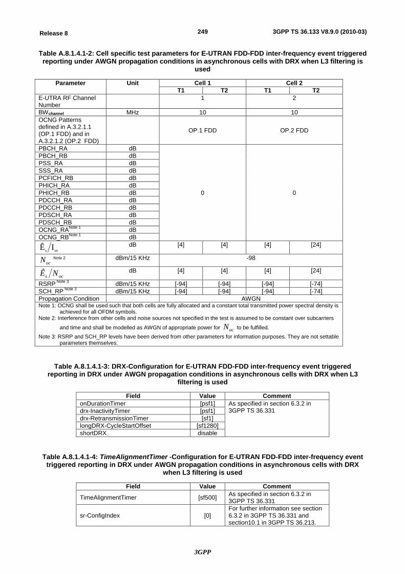
3GPP
249Release 8 3GPP TS 36.133 V8.9.0 (2010-03)
Table A.8.1.4.1-2: Cell specific test parameters for E-UTRAN FDD-FDD inter-frequency event triggered reporting under AWGN propagation conditions in asynchronous cells with DRX when L3 filtering is
used
Parameter Unit Cell 1 Cell 2 T1 T2 T1 T2
E-UTRA RF Channel Number
1 2
BWchannel MHz 10 10 OCNG Patterns defined in A.3.2.1.1 (OP.1 FDD) and in A.3.2.1.2 (OP.2 FDD)
OP.1 FDD OP.2 FDD
PBCH_RA dB
0 0
PBCH_RB dB PSS_RA dB SSS_RA dB PCFICH_RB dB PHICH_RA dB PHICH_RB dB PDCCH_RA dB PDCCH_RB dB PDSCH_RA dB PDSCH_RB dB OCNG_RANote 1 dB OCNG_RBNote 1 dB
ots IÊ dB [4] [4] [4] [24]
ocN Note 2 dBm/15 KHz -98
ocs NÊ dB [4] [4] [4] [24]
RSRP Note 3 dBm/15 KHz [-94] [-94] [-94] [-74] SCH_RP Note 3 dBm/15 KHz [-94] [-94] [-94] [-74] Propagation Condition AWGN Note 1: OCNG shall be used such that both cells are fully allocated and a constant total transmitted power spectral density is
achieved for all OFDM symbols. Note 2: Interference from other cells and noise sources not specified in the test is assumed to be constant over subcarriers
and time and shall be modelled as AWGN of appropriate power for ocN to be fulfilled. Note 3: RSRP and SCH_RP levels have been derived from other parameters for information purposes. They are not settable
parameters themselves.
Table A.8.1.4.1-3: DRX-Configuration for E-UTRAN FDD-FDD inter-frequency event triggered reporting in DRX under AWGN propagation conditions in asynchronous cells with DRX when L3
filtering is used
Field Value Comment onDurationTimer [psf1] As specified in section 6.3.2 in
3GPP TS 36.331 drx-InactivityTimer [psf1] drx-RetransmissionTimer [sf1] longDRX-CycleStartOffset [sf1280] shortDRX disable
Table A.8.1.4.1-4: TimeAlignmentTimer -Configuration for E-UTRAN FDD-FDD inter-frequency event triggered reporting in DRX under AWGN propagation conditions in asynchronous cells with DRX
when L3 filtering is used
Field Value Comment
TimeAlignmentTimer [sf500] As specified in section 6.3.2 in 3GPP TS 36.331
sr-ConfigIndex [0] For further information see section 6.3.2 in 3GPP TS 36.331 and section10.1 in 3GPP TS 36.213.
3GPP
250Release 8 3GPP TS 36.133 V8.9.0 (2010-03)
A.8.1.4.2 Test Requirements
The UE shall send one Event A3 triggered measurement report, with a measurement reporting delay less than 6400 ms from the beginning of time period T2. The measurement reporting delay is defined as the time from the beginning of time period T2 to the moment when the UE starts to send preambles on the PRACH for scheduling request (SR) to obtain allocation to send the measurement report on PUSCH.
The UE shall not send event triggered measurement reports, as long as the reporting criteria are not fulfilled.
The rate of correct events observed during repeated tests shall be at least 90%.
NOTE 1: The actual overall delays measured in the test may be up to one DRX cycle higher than the measurement reporting delays above because UE is allowed to delay the initiation of the measurement reporting procedure to the next until the Active Time.
NOTE 2: In order to calculate the rate of correct events the system simulator shall verify that it has received correct Event A3 measurement report.
A.8.2 E-UTRAN TDD Intra-frequency Measurements
A.8.2.1 E-UTRAN TDD-TDD intra-frequency event triggered reporting under fading propagation conditions in synchronous cells
A.8.2.1.1 Test Purpose and Environment
The purpose of this test is to verify that the UE makes correct reporting of an event. This test will partly verify the TDD intra-frequency cell search requirements in section 8.1.2.2.2.1.
The test parameters are given in Table A.8.2.1.1-1 and A.8.2.1.1-2 below. In the measurement control information it is indicated to the UE that event-triggered reporting with Event A3 is used. PDCCHs indicating new transmissions should be sent continuously to ensure that the UE would not enter the DRX state. The test consists of two successive time periods, with time duration of T1, and T2 respectively. During time duration T1, the UE shall not have any timing information of cell 2.
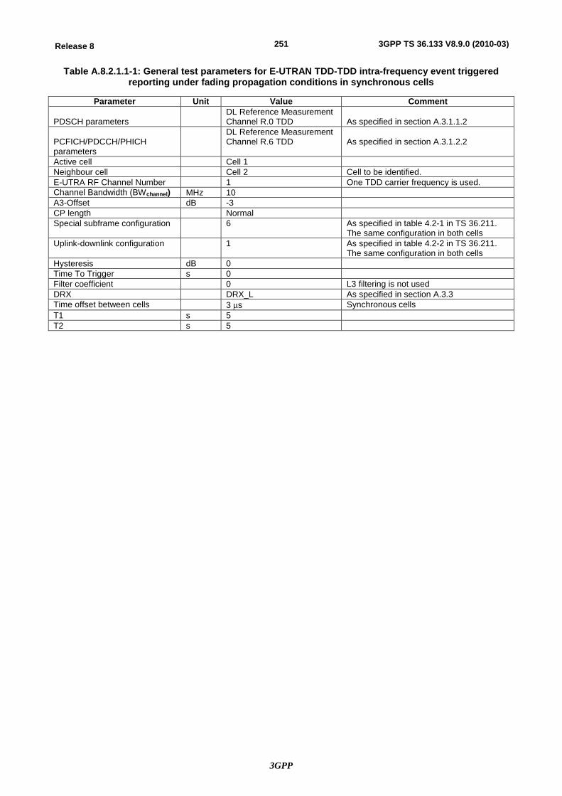
3GPP
251Release 8 3GPP TS 36.133 V8.9.0 (2010-03)
Table A.8.2.1.1-1: General test parameters for E-UTRAN TDD-TDD intra-frequency event triggered reporting under fading propagation conditions in synchronous cells
Parameter Unit Value Comment PDSCH parameters
DL Reference Measurement Channel R.0 TDD
As specified in section A.3.1.1.2
PCFICH/PDCCH/PHICH parameters
DL Reference Measurement Channel R.6 TDD
As specified in section A.3.1.2.2
Active cell Cell 1 Neighbour cell Cell 2 Cell to be identified. E-UTRA RF Channel Number 1 One TDD carrier frequency is used. Channel Bandwidth (BWchannel) MHz 10 A3-Offset dB -3 CP length Normal Special subframe configuration 6 As specified in table 4.2-1 in TS 36.211.
The same configuration in both cells Uplink-downlink configuration 1 As specified in table 4.2-2 in TS 36.211.
The same configuration in both cells Hysteresis dB 0 Time To Trigger s 0 Filter coefficient 0 L3 filtering is not used DRX DRX_L As specified in section A.3.3 Time offset between cells 3 ms Synchronous cells T1 s 5 T2 s 5
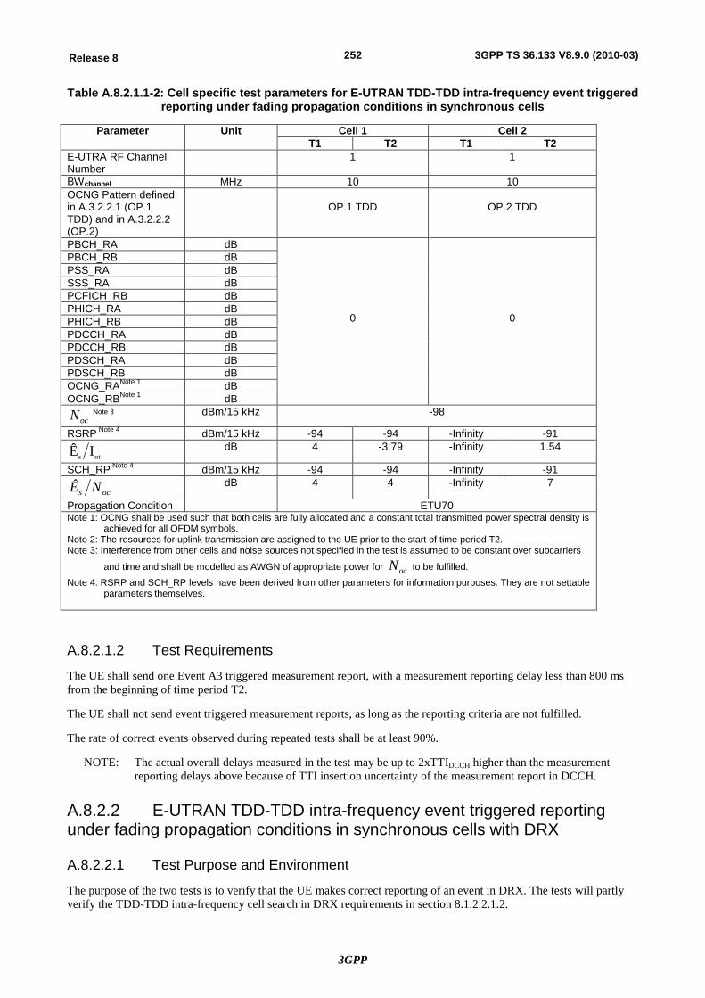
3GPP
252Release 8 3GPP TS 36.133 V8.9.0 (2010-03)
Table A.8.2.1.1-2: Cell specific test parameters for E-UTRAN TDD-TDD intra-frequency event triggered reporting under fading propagation conditions in synchronous cells
Parameter Unit Cell 1 Cell 2 T1 T2 T1 T2
E-UTRA RF Channel Number
1 1
BWchannel MHz 10 10 OCNG Pattern defined in A.3.2.2.1 (OP.1 TDD) and in A.3.2.2.2 (OP.2)
OP.1 TDD
OP.2 TDD
PBCH_RA dB
0
0
PBCH_RB dB PSS_RA dB SSS_RA dB PCFICH_RB dB PHICH_RA dB PHICH_RB dB PDCCH_RA dB PDCCH_RB dB PDSCH_RA dB PDSCH_RB dB OCNG_RANote 1 dB OCNG_RBNote 1 dB
ocN Note 3 dBm/15 kHz -98
RSRP Note 4 dBm/15 kHz -94 -94 -Infinity -91
ots IÊ dB 4 -3.79 -Infinity 1.54
SCH_RP Note 4 dBm/15 kHz -94 -94 -Infinity -91
ocs NÊ dB 4 4 -Infinity 7
Propagation Condition ETU70 Note 1: OCNG shall be used such that both cells are fully allocated and a constant total transmitted power spectral density is
achieved for all OFDM symbols. Note 2: The resources for uplink transmission are assigned to the UE prior to the start of time period T2. Note 3: Interference from other cells and noise sources not specified in the test is assumed to be constant over subcarriers
and time and shall be modelled as AWGN of appropriate power for ocN to be fulfilled. Note 4: RSRP and SCH_RP levels have been derived from other parameters for information purposes. They are not settable
parameters themselves.
A.8.2.1.2 Test Requirements
The UE shall send one Event A3 triggered measurement report, with a measurement reporting delay less than 800 ms from the beginning of time period T2.
The UE shall not send event triggered measurement reports, as long as the reporting criteria are not fulfilled.
The rate of correct events observed during repeated tests shall be at least 90%.
NOTE: The actual overall delays measured in the test may be up to 2xTTIDCCH higher than the measurement reporting delays above because of TTI insertion uncertainty of the measurement report in DCCH.
A.8.2.2 E-UTRAN TDD-TDD intra-frequency event triggered reporting under fading propagation conditions in synchronous cells with DRX
A.8.2.2.1 Test Purpose and Environment
The purpose of the two tests is to verify that the UE makes correct reporting of an event in DRX. The tests will partly verify the TDD-TDD intra-frequency cell search in DRX requirements in section 8.1.2.2.1.2.
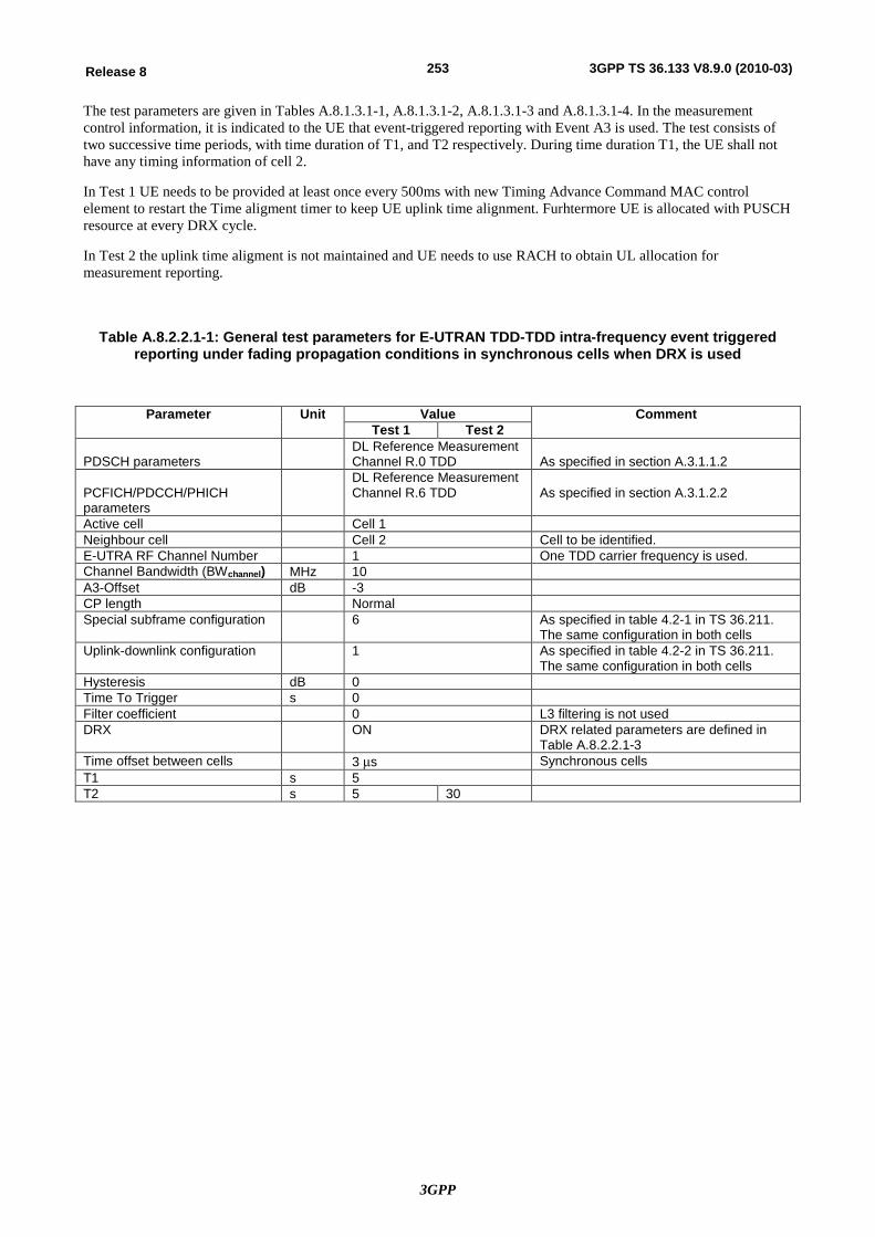
3GPP
253Release 8 3GPP TS 36.133 V8.9.0 (2010-03)
The test parameters are given in Tables A.8.1.3.1-1, A.8.1.3.1-2, A.8.1.3.1-3 and A.8.1.3.1-4. In the measurement control information, it is indicated to the UE that event-triggered reporting with Event A3 is used. The test consists of two successive time periods, with time duration of T1, and T2 respectively. During time duration T1, the UE shall not have any timing information of cell 2.
In Test 1 UE needs to be provided at least once every 500ms with new Timing Advance Command MAC control element to restart the Time aligment timer to keep UE uplink time alignment. Furhtermore UE is allocated with PUSCH resource at every DRX cycle.
In Test 2 the uplink time aligment is not maintained and UE needs to use RACH to obtain UL allocation for measurement reporting.
Table A.8.2.2.1-1: General test parameters for E-UTRAN TDD-TDD intra-frequency event triggered reporting under fading propagation conditions in synchronous cells when DRX is used
Parameter Unit Value Comment Test 1 Test 2
PDSCH parameters
DL Reference Measurement Channel R.0 TDD
As specified in section A.3.1.1.2
PCFICH/PDCCH/PHICH parameters
DL Reference Measurement Channel R.6 TDD
As specified in section A.3.1.2.2
Active cell Cell 1 Neighbour cell Cell 2 Cell to be identified. E-UTRA RF Channel Number 1 One TDD carrier frequency is used. Channel Bandwidth (BWchannel) MHz 10 A3-Offset dB -3 CP length Normal Special subframe configuration 6 As specified in table 4.2-1 in TS 36.211.
The same configuration in both cells Uplink-downlink configuration 1 As specified in table 4.2-2 in TS 36.211.
The same configuration in both cells Hysteresis dB 0 Time To Trigger s 0 Filter coefficient 0 L3 filtering is not used DRX ON DRX related parameters are defined in
Table A.8.2.2.1-3 Time offset between cells 3 ms Synchronous cells T1 s 5 T2 s 5 30
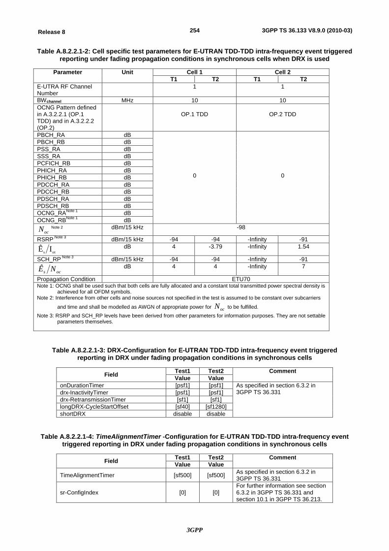
3GPP
254Release 8 3GPP TS 36.133 V8.9.0 (2010-03)
Table A.8.2.2.1-2: Cell specific test parameters for E-UTRAN TDD-TDD intra-frequency event triggered reporting under fading propagation conditions in synchronous cells when DRX is used
Parameter Unit Cell 1 Cell 2 T1 T2 T1 T2
E-UTRA RF Channel Number
1 1
BWchannel MHz 10 10 OCNG Pattern defined in A.3.2.2.1 (OP.1 TDD) and in A.3.2.2.2 (OP.2)
OP.1 TDD
OP.2 TDD
PBCH_RA dB
0
0
PBCH_RB dB PSS_RA dB SSS_RA dB PCFICH_RB dB PHICH_RA dB PHICH_RB dB PDCCH_RA dB PDCCH_RB dB PDSCH_RA dB PDSCH_RB dB OCNG_RANote 1 dB OCNG_RBNote 1 dB
ocN Note 2 dBm/15 kHz -98
RSRP Note 3 dBm/15 kHz -94 -94 -Infinity -91
ots IÊ dB 4 -3.79 -Infinity 1.54
SCH_RP Note 3 dBm/15 kHz -94 -94 -Infinity -91
ocs NÊ dB 4 4 -Infinity 7
Propagation Condition ETU70 Note 1: OCNG shall be used such that both cells are fully allocated and a constant total transmitted power spectral density is
achieved for all OFDM symbols. Note 2: Interference from other cells and noise sources not specified in the test is assumed to be constant over subcarriers
and time and shall be modelled as AWGN of appropriate power for ocN to be fulfilled. Note 3: RSRP and SCH_RP levels have been derived from other parameters for information purposes. They are not settable
parameters themselves.
Table A.8.2.2.1-3: DRX-Configuration for E-UTRAN TDD-TDD intra-frequency event triggered reporting in DRX under fading propagation conditions in synchronous cells
Field Test1 Test2 Comment Value Value
onDurationTimer [psf1] [psf1] As specified in section 6.3.2 in 3GPP TS 36.331 drx-InactivityTimer [psf1] [psf1]
drx-RetransmissionTimer [sf1] [sf1] longDRX-CycleStartOffset [sf40] [sf1280] shortDRX disable disable
Table A.8.2.2.1-4: TimeAlignmentTimer -Configuration for E-UTRAN TDD-TDD intra-frequency event triggered reporting in DRX under fading propagation conditions in synchronous cells
Field Test1 Test2 Comment Value Value
TimeAlignmentTimer [sf500] [sf500] As specified in section 6.3.2 in 3GPP TS 36.331
sr-ConfigIndex [0] [0] For further information see section 6.3.2 in 3GPP TS 36.331 and section 10.1 in 3GPP TS 36.213.
3GPP
255Release 8 3GPP TS 36.133 V8.9.0 (2010-03)
A.8.2.2.2 Test Requirements
In Test 1, the UE shall send one Event A3 triggered measurement report, with a measurement reporting delay less than 800 ms from the beginning of time period T2. The measurement reporting delay is defined as the time from the beginning of time period T2 to the moment when the UE send the measurement report on PUSCH.
In Test 2, the UE shall send one Event A3 triggered measurement report, with a measurement reporting delay less than 25600 ms from the beginning of time period T2. The measurement reporting delay is defined as the time from the beginning of time period T2 to the moment when the UE starts to send preambles on the PRACH for scheduling request (SR) to obtain allocation to send the measurement report on PUSCH.
The UE shall not send event triggered measurement reports, as long as the reporting criteria are not fulfilled.
The rate of correct events observed during repeated tests shall be at least 90%.
NOTE: The actual overall delays measured in the test may be up to one DRX cycle higher than the measurement reporting delays above because UE is allowed to delay the initiation of the measurement reporting procedure to the next until the Active Time.
NOTE 2: In order to calculate the rate of correct events the system simulator shall verify that it has received correct Event A3 measurement report.
A.8.3 E-UTRAN FDD - FDD Inter-frequency Measurements
A.8.3.1 E-UTRAN FDD-FDD Inter-frequency event triggered reporting under fading propagation conditions in asynchronous cells
A.8.3.1.1 Test Purpose and Environment
The purpose of this test is to verify that the UE makes correct reporting of an event. This test will partly verify the FDD-FDD inter-frequency cell search requirements in section 8.1.2.3.
The test parameters are given in Tables A.8.3.1.1-1 and A.8.3.1.1-2. In this test, there are two cells on different carrier frequencies and gap pattern configuration # 0 as defined in Table 8.1.2.1-1 is provided.
In the measurement control information, it is indicated to the UE that event-triggered reporting with Event A3 is used. The test consists of two successive time periods, with time duration of T1, and T2 respectively. During time duration T1, the UE shall not have any timing information of cell 2.
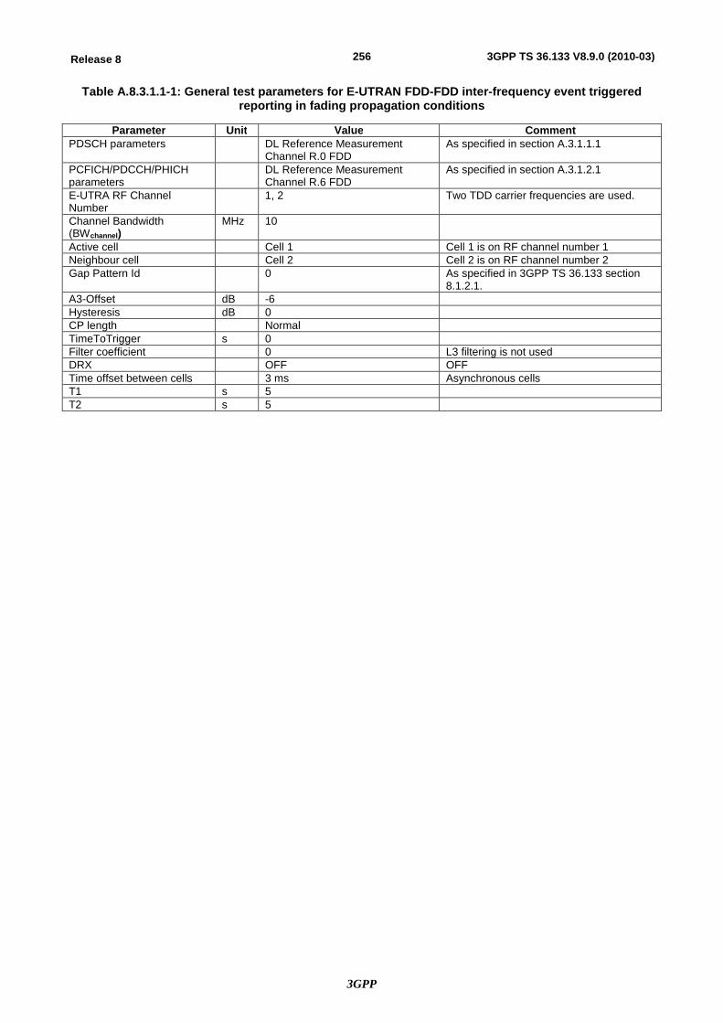
3GPP
256Release 8 3GPP TS 36.133 V8.9.0 (2010-03)
Table A.8.3.1.1-1: General test parameters for E-UTRAN FDD-FDD inter-frequency event triggered reporting in fading propagation conditions
Parameter Unit Value Comment PDSCH parameters DL Reference Measurement
Channel R.0 FDD As specified in section A.3.1.1.1
PCFICH/PDCCH/PHICH parameters
DL Reference Measurement Channel R.6 FDD
As specified in section A.3.1.2.1
E-UTRA RF Channel Number
1, 2 Two TDD carrier frequencies are used.
Channel Bandwidth (BWchannel)
MHz 10
Active cell Cell 1 Cell 1 is on RF channel number 1 Neighbour cell Cell 2 Cell 2 is on RF channel number 2 Gap Pattern Id 0 As specified in 3GPP TS 36.133 section
8.1.2.1. A3-Offset dB -6 Hysteresis dB 0 CP length Normal TimeToTrigger s 0 Filter coefficient 0 L3 filtering is not used DRX OFF OFF Time offset between cells 3 ms Asynchronous cells T1 s 5 T2 s 5

3GPP
257Release 8 3GPP TS 36.133 V8.9.0 (2010-03)
Table A.8.3.1.1-2: Cell specific test parameters for E-UTRAN FDD-FDD inter-frequency event triggered reporting under fading propagation conditions in synchronous cells
Parameter Unit Cell 1 Cell 2 T1 T2 T1 T2
E-UTRA RF Channel Number
1 2
BWchannel MHz 10 10 OCNG Patterns defined in A.3.2.1.1 (OP.1 FDD) and in A.3.2.1.2 (OP.2 FDD)
OP.1 FDD
OP.2 FDD
PBCH_RA dB
0
0
PBCH_RB dB PSS_RA dB SSS_RA dB PCFICH_RB dB PHICH_RA dB PHICH_RB dB PDCCH_RA dB PDCCH_RB dB PDSCH_RA dB PDSCH_RB dB OCNG_RANote 1 dB OCNG_RBNote 1 dB
ocN Note 3 dBm/15 kHz -98
RSRP Note 4 dBm/15 kHz -94 -94 -Infinity -91
ots IÊ dB 4 4 -Infinity 7
SCH_RP Note 4 dBm/15 kHz -94 -94 -Infinity -91
ocs NÊ dB 4 4 -Infinity 7
Propagation Condition ETU70 Note 1: OCNG shall be used such that both cells are fully allocated and a constant total transmitted power spectral density is
achieved for all OFDM symbols. Note 2: The resources for uplink transmission are assigned to the UE prior to the start of time period T2. Note 3: Interference from other cells and noise sources not specified in the test is assumed to be constant over subcarriers
and time and shall be modelled as AWGN of appropriate power for ocN to be fulfilled. Note 4: RSRP and SCH_RP levels have been derived from other parameters for information purposes. They are not settable
parameters themselves.
A.8.3.1.2 Test Requirements
The UE shall send one Event A3 triggered measurement report, with a measurement reporting delay less than 3840 ms from the beginning of time period T2.
The UE shall not send event triggered measurement reports, as long as the reporting criteria are not fulfilled.
The rate of correct events observed during repeated tests shall be at least 90%.
NOTE: The actual overall delays measured in the test may be up to 2xTTIDCCH higher than the measurement reporting delays above because of TTI insertion uncertainty of the measurement report in DCCH.
A.8.3.2 E-UTRAN FDD-FDD Inter-frequency event triggered reporting when DRX is used under fading propagation conditions in asynchronous cells
A.8.3.2.1 Test Purpose and Environment
The purpose of these tests is to verify that the UE makes correct reporting of an event in DRX. These test will partly verify the FDD-FDD inter-frequency cell search requirements when DRX is used in section 8.1.2.3.
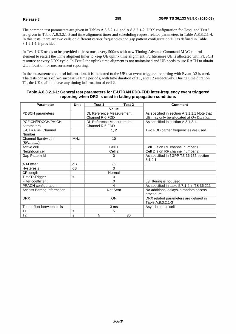
3GPP
258Release 8 3GPP TS 36.133 V8.9.0 (2010-03)
The common test parameters are given in Tables A.8.3.2.1-1 and A.8.3.2.1-2. DRX configuration for Test1 and Test2 are given in Table A.8.3.2.1-3 and time alignment timer and scheduling request related parameters in Table A.8.3.2.1-4. In this tests, there are two cells on different carrier frequencies and gap pattern configuration # 0 as defined in Table 8.1.2.1-1 is provided.
In Test 1 UE needs to be provided at least once every 500ms with new Timing Advance Command MAC control element to restart the Time aligment timer to keep UE uplink time alignment. Furhtermore UE is allocated with PUSCH resource at every DRX cycle. In Test 2 the uplink time aligment is not maintained and UE needs to use RACH to obtain UL allocation for measurement reporting.
In the measurement control information, it is indicated to the UE that event-triggered reporting with Event A3 is used. The tests consists of two successive time periods, with time duration of T1, and T2 respectively. During time duration T1, the UE shall not have any timing information of cell 2.
Table A.8.3.2.1-1: General test parameters for E-UTRAN FDD-FDD inter-frequency event triggered reporting when DRX is used in fading propagation conditions
Parameter Unit Test 1 Test 2 Comment Value
PDSCH parameters DL Reference Measurement Channel R.0 FDD
As specified in section A.3.1.1.1 Note that UE may only be allocated at On Duration
PCFICH/PDCCH/PHICH parameters
DL Reference Measurement Channel R.6 FDD
As specified in section A.3.1.2.1.
E-UTRA RF Channel Number
1, 2 Two FDD carrier frequencies are used.
Channel Bandwidth (BWchannel)
MHz 10
Active cell Cell 1 Cell 1 is on RF channel number 1 Neighbour cell Cell 2 Cell 2 is on RF channel number 2 Gap Pattern Id 0 As specified in 3GPP TS 36.133 section
8.1.2.1. A3-Offset dB -6 Hysteresis dB 0 CP length Normal TimeToTrigger s 0 Filter coefficient 0 L3 filtering is not used PRACH configuration 4 As specified in table 5.7.1-2 in TS 36.211 Access Barring Information - Not Sent No additional delays in random access
procedure. DRX ON DRX related parameters are defined in
Table A.8.3.2.1-3 Time offset between cells 3 ms Asynchronous cells T1 s 5 T2 s 5 30
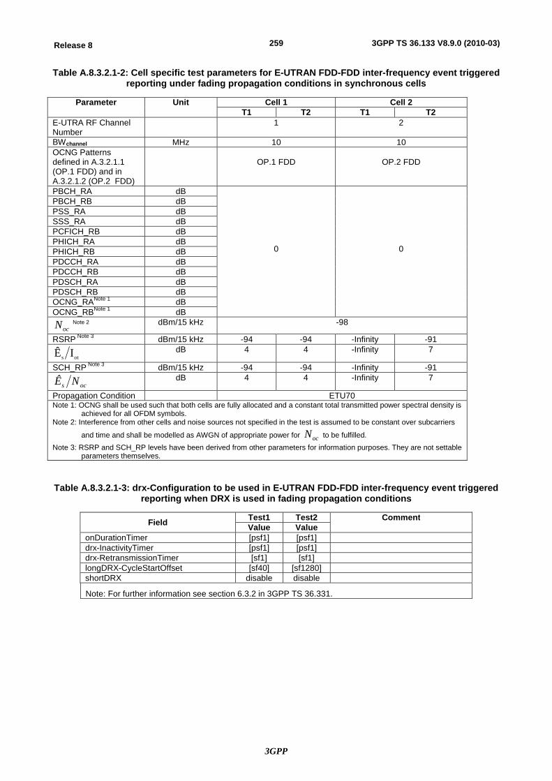
3GPP
259Release 8 3GPP TS 36.133 V8.9.0 (2010-03)
Table A.8.3.2.1-2: Cell specific test parameters for E-UTRAN FDD-FDD inter-frequency event triggered reporting under fading propagation conditions in synchronous cells
Parameter Unit Cell 1 Cell 2 T1 T2 T1 T2
E-UTRA RF Channel Number
1 2
BWchannel MHz 10 10 OCNG Patterns defined in A.3.2.1.1 (OP.1 FDD) and in A.3.2.1.2 (OP.2 FDD)
OP.1 FDD
OP.2 FDD
PBCH_RA dB
0
0
PBCH_RB dB PSS_RA dB SSS_RA dB PCFICH_RB dB PHICH_RA dB PHICH_RB dB PDCCH_RA dB PDCCH_RB dB PDSCH_RA dB PDSCH_RB dB OCNG_RANote 1 dB OCNG_RBNote 1 dB
ocN Note 2 dBm/15 kHz -98
RSRP Note 3 dBm/15 kHz -94 -94 -Infinity -91
ots IÊ dB 4 4 -Infinity 7
SCH_RP Note 3 dBm/15 kHz -94 -94 -Infinity -91
ocs NÊ dB 4 4 -Infinity 7
Propagation Condition ETU70 Note 1: OCNG shall be used such that both cells are fully allocated and a constant total transmitted power spectral density is
achieved for all OFDM symbols. Note 2: Interference from other cells and noise sources not specified in the test is assumed to be constant over subcarriers
and time and shall be modelled as AWGN of appropriate power for ocN to be fulfilled. Note 3: RSRP and SCH_RP levels have been derived from other parameters for information purposes. They are not settable
parameters themselves.
Table A.8.3.2.1-3: drx-Configuration to be used in E-UTRAN FDD-FDD inter-frequency event triggered reporting when DRX is used in fading propagation conditions
Field Test1 Test2 Comment Value Value
onDurationTimer [psf1] [psf1] drx-InactivityTimer [psf1] [psf1] drx-RetransmissionTimer [sf1] [sf1] longDRX-CycleStartOffset [sf40] [sf1280] shortDRX disable disable
Note: For further information see section 6.3.2 in 3GPP TS 36.331.
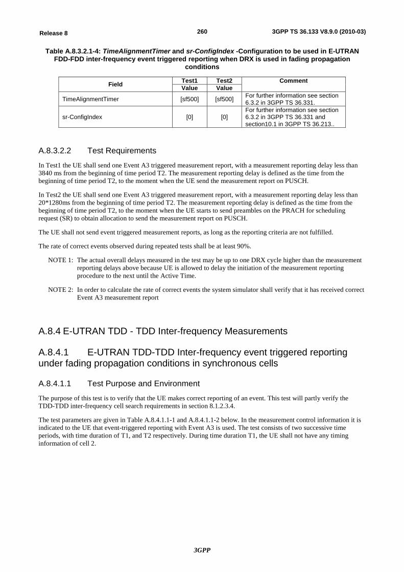
3GPP
260Release 8 3GPP TS 36.133 V8.9.0 (2010-03)
Table A.8.3.2.1-4: TimeAlignmentTimer and sr-ConfigIndex -Configuration to be used in E-UTRAN FDD-FDD inter-frequency event triggered reporting when DRX is used in fading propagation
conditions
Field Test1 Test2 Comment Value Value
TimeAlignmentTimer [sf500] [sf500] For further information see section 6.3.2 in 3GPP TS 36.331.
sr-ConfigIndex [0] [0] For further information see section 6.3.2 in 3GPP TS 36.331 and section10.1 in 3GPP TS 36.213..
A.8.3.2.2 Test Requirements
In Test1 the UE shall send one Event A3 triggered measurement report, with a measurement reporting delay less than 3840 ms from the beginning of time period T2. The measurement reporting delay is defined as the time from the beginning of time period T2, to the moment when the UE send the measurement report on PUSCH.
In Test2 the UE shall send one Event A3 triggered measurement report, with a measurement reporting delay less than 20*1280ms from the beginning of time period T2. The measurement reporting delay is defined as the time from the beginning of time period T2, to the moment when the UE starts to send preambles on the PRACH for scheduling request (SR) to obtain allocation to send the measurement report on PUSCH.
The UE shall not send event triggered measurement reports, as long as the reporting criteria are not fulfilled.
The rate of correct events observed during repeated tests shall be at least 90%.
NOTE 1: The actual overall delays measured in the test may be up to one DRX cycle higher than the measurement reporting delays above because UE is allowed to delay the initiation of the measurement reporting procedure to the next until the Active Time.
NOTE 2: In order to calculate the rate of correct events the system simulator shall verify that it has received correct Event A3 measurement report
A.8.4 E-UTRAN TDD - TDD Inter-frequency Measurements
A.8.4.1 E-UTRAN TDD-TDD Inter-frequency event triggered reporting under fading propagation conditions in synchronous cells
A.8.4.1.1 Test Purpose and Environment
The purpose of this test is to verify that the UE makes correct reporting of an event. This test will partly verify the TDD-TDD inter-frequency cell search requirements in section 8.1.2.3.4.
The test parameters are given in Table A.8.4.1.1-1 and A.8.4.1.1-2 below. In the measurement control information it is indicated to the UE that event-triggered reporting with Event A3 is used. The test consists of two successive time periods, with time duration of T1, and T2 respectively. During time duration T1, the UE shall not have any timing information of cell 2.
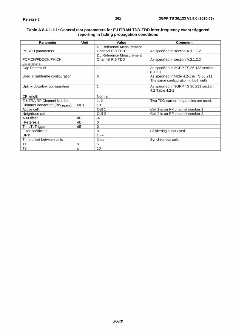
3GPP
261Release 8 3GPP TS 36.133 V8.9.0 (2010-03)
Table A.8.4.1.1-1: General test parameters for E-UTRAN TDD-TDD inter-frequency event triggered reporting in fading propagation conditions
Parameter Unit Value Comment PDSCH parameters
DL Reference Measurement Channel R.0 TDD
As specified in section A.3.1.1.2
PCFICH/PDCCH/PHICH parameters
DL Reference Measurement Channel R.6 TDD
As specified in section A.3.1.2.2
Gap Pattern Id 1 As specified in 3GPP TS 36.133 section 8.1.2.1.
Special subframe configuration 6 As specified in table 4.2-1 in TS 36.211. The same configuration in both cells
Uplink-downlink configuration 1 As specified in 3GPP TS 36.211 section 4.2 Table 4.2-2
CP length Normal E-UTRA RF Channel Number 1, 2 Two TDD carrier frequencies are used. Channel Bandwidth (BWchannel) MHz 10 Active cell Cell 1 Cell 1 is on RF channel number 1 Neighbour cell Cell 2 Cell 2 is on RF channel number 2 A3-Offset dB -6 Hysteresis dB 0 TimeToTrigger dB 0 Filter coefficient 0 L3 filtering is not used DRX OFF Time offset between cells 3 ms Synchronous cells T1 s 5 T2 s 10
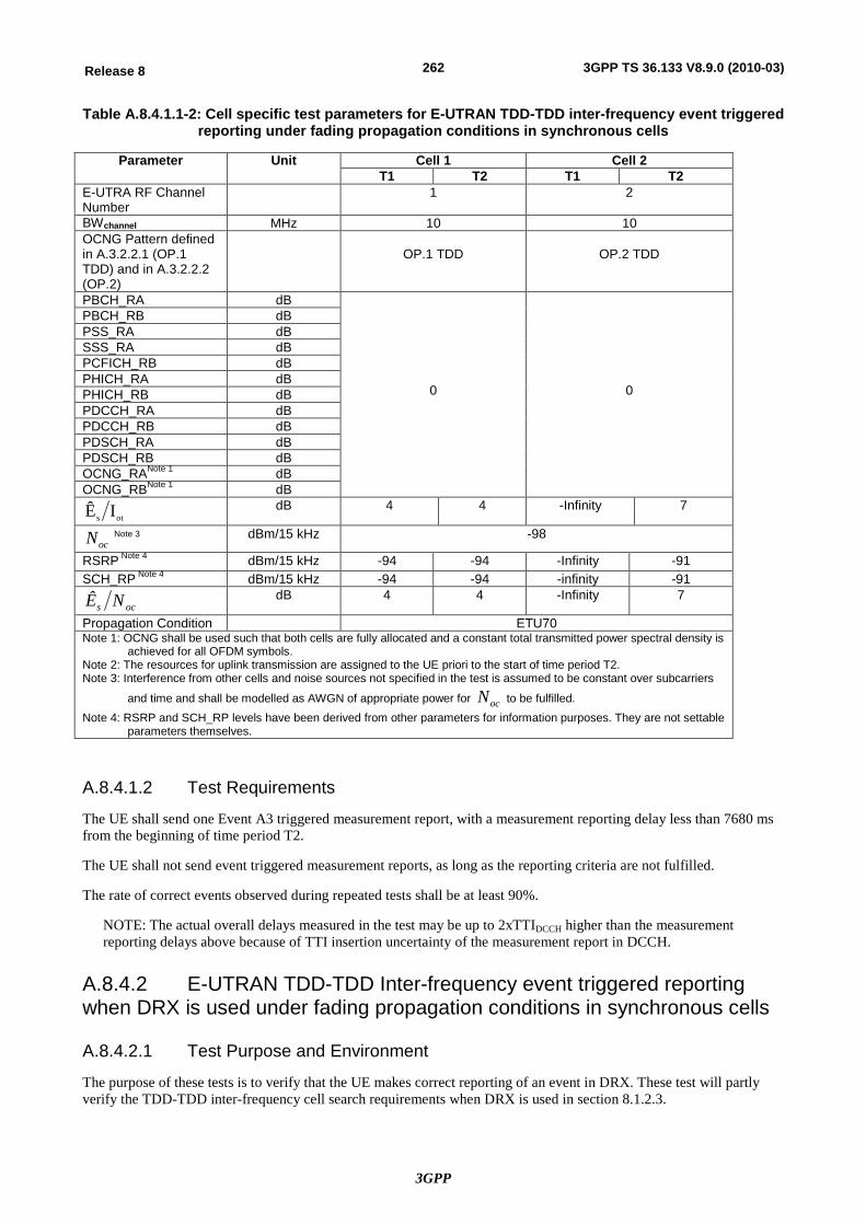
3GPP
262Release 8 3GPP TS 36.133 V8.9.0 (2010-03)
Table A.8.4.1.1-2: Cell specific test parameters for E-UTRAN TDD-TDD inter-frequency event triggered reporting under fading propagation conditions in synchronous cells
Parameter Unit Cell 1 Cell 2 T1 T2 T1 T2
E-UTRA RF Channel Number
1 2
BWchannel MHz 10 10 OCNG Pattern defined in A.3.2.2.1 (OP.1 TDD) and in A.3.2.2.2 (OP.2)
OP.1 TDD
OP.2 TDD
PBCH_RA dB
0
0
PBCH_RB dB PSS_RA dB SSS_RA dB PCFICH_RB dB PHICH_RA dB PHICH_RB dB PDCCH_RA dB PDCCH_RB dB PDSCH_RA dB PDSCH_RB dB OCNG_RANote 1 dB OCNG_RBNote 1 dB
ots IÊ dB 4 4 -Infinity 7
ocN Note 3 dBm/15 kHz -98
RSRP Note 4 dBm/15 kHz -94 -94 -Infinity -91 SCH_RP Note 4 dBm/15 kHz -94 -94 -infinity -91
ocs NÊ dB 4 4 -Infinity 7
Propagation Condition ETU70 Note 1: OCNG shall be used such that both cells are fully allocated and a constant total transmitted power spectral density is
achieved for all OFDM symbols. Note 2: The resources for uplink transmission are assigned to the UE priori to the start of time period T2. Note 3: Interference from other cells and noise sources not specified in the test is assumed to be constant over subcarriers
and time and shall be modelled as AWGN of appropriate power for ocN to be fulfilled. Note 4: RSRP and SCH_RP levels have been derived from other parameters for information purposes. They are not settable
parameters themselves.
A.8.4.1.2 Test Requirements
The UE shall send one Event A3 triggered measurement report, with a measurement reporting delay less than 7680 ms from the beginning of time period T2.
The UE shall not send event triggered measurement reports, as long as the reporting criteria are not fulfilled.
The rate of correct events observed during repeated tests shall be at least 90%.
NOTE: The actual overall delays measured in the test may be up to 2xTTIDCCH higher than the measurement reporting delays above because of TTI insertion uncertainty of the measurement report in DCCH.
A.8.4.2 E-UTRAN TDD-TDD Inter-frequency event triggered reporting when DRX is used under fading propagation conditions in synchronous cells
A.8.4.2.1 Test Purpose and Environment
The purpose of these tests is to verify that the UE makes correct reporting of an event in DRX. These test will partly verify the TDD-TDD inter-frequency cell search requirements when DRX is used in section 8.1.2.3.
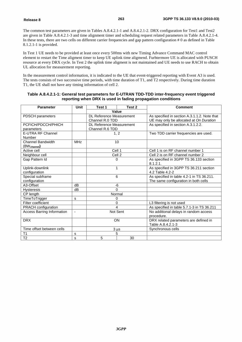
3GPP
263Release 8 3GPP TS 36.133 V8.9.0 (2010-03)
The common test parameters are given in Tables A.8.4.2.1-1 and A.8.4.2.1-2. DRX configuration for Test1 and Test2 are given in Table A.8.4.2.1-3 and time alignment timer and scheduling request related parameters in Table A.8.4.2.1-4. In these tests, there are two cells on different carrier frequencies and gap pattern configuration # 0 as defined in Table 8.1.2.1-1 is provided.
In Test 1 UE needs to be provided at least once every 500ms with new Timing Advance Command MAC control element to restart the Time aligment timer to keep UE uplink time aligmend. Furhtermore UE is allocated with PUSCH resource at every DRX cycle. In Test 2 the uplink time aligment is not maintained and UE needs to use RACH to obtain UL allocation for measurement reporting.
In the measurement control information, it is indicated to the UE that event-triggered reporting with Event A3 is used. The tests consists of two successive time periods, with time duration of T1, and T2 respectively. During time duration T1, the UE shall not have any timing information of cell 2.
Table A.8.4.2.1-1: General test parameters for E-UTRAN TDD-TDD inter-frequency event triggered reporting when DRX is used in fading propagation conditions
Parameter Unit Test 1 Test 2 Comment Value
PDSCH parameters DL Reference Measurement Channel R.0 TDD
As specified in section A.3.1.1.2. Note that UE may only be allocated at On Duration
PCFICH/PDCCH/PHICH parameters
DL Reference Measurement Channel R.6 TDD
As specified in section A.3.1.2.2.
E-UTRA RF Channel Number
1, 2 Two TDD carrier frequencies are used.
Channel Bandwidth (BWchannel)
MHz 10
Active cell Cell 1 Cell 1 is on RF channel number 1 Neighbour cell Cell 2 Cell 2 is on RF channel number 2 Gap Pattern Id 0 As specified in 3GPP TS 36.133 section
8.1.2.1. Uplink-downlink configuration
1 As specified in 3GPP TS 36.211 section 4.2 Table 4.2-2
Special subframe configuration
6 As specified in table 4.2-1 in TS 36.211. The same configuration in both cells
A3-Offset dB -6 Hysteresis dB 0 CP length Normal TimeToTrigger s 0 Filter coefficient 0 L3 filtering is not used PRACH configuration 4 As specified in table 5.7.1-3 in TS 36.211 Access Barring Information - Not Sent No additional delays in random access
procedure. DRX ON DRX related parameters are defined in
Table A.8.4.2.1-3 Time offset between cells 3 ms Synchronous cells T1 s 5 T2 s 5 30
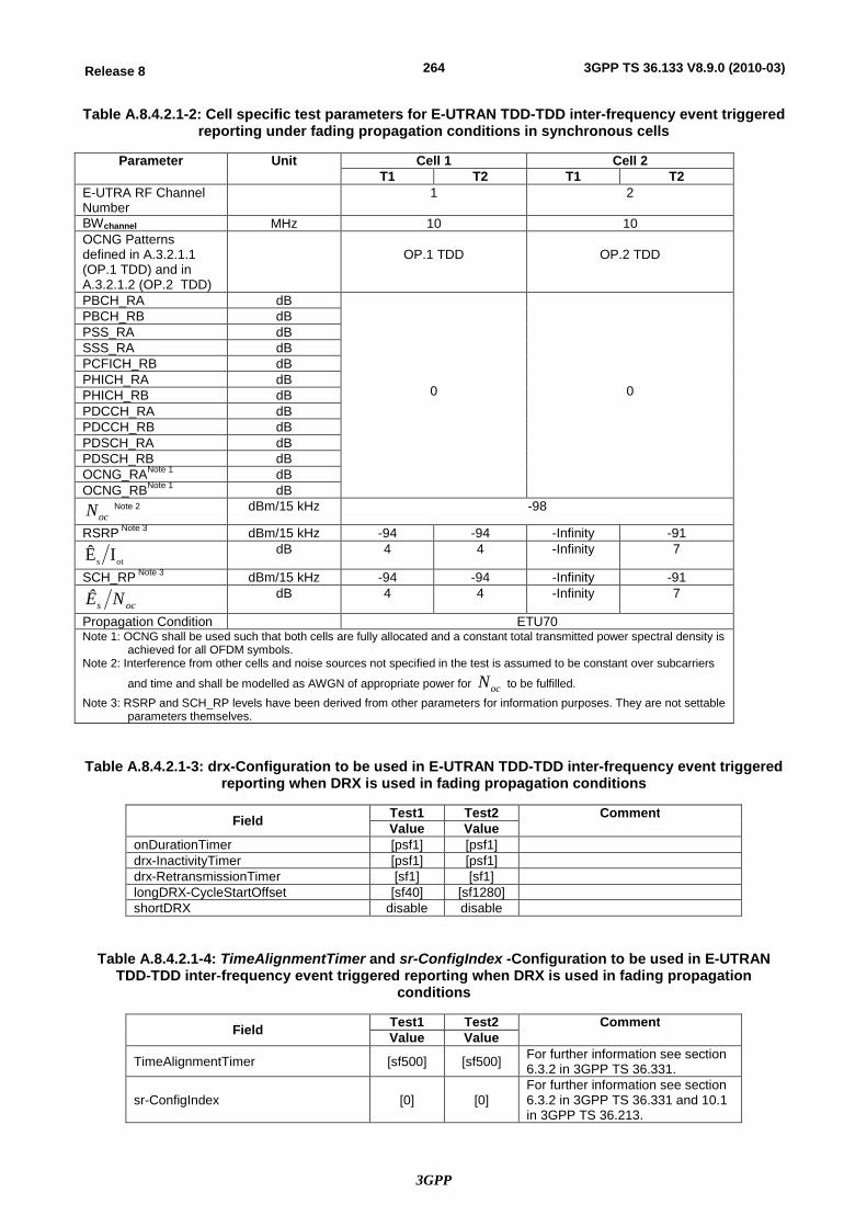
3GPP
264Release 8 3GPP TS 36.133 V8.9.0 (2010-03)
Table A.8.4.2.1-2: Cell specific test parameters for E-UTRAN TDD-TDD inter-frequency event triggered reporting under fading propagation conditions in synchronous cells
Parameter Unit Cell 1 Cell 2 T1 T2 T1 T2
E-UTRA RF Channel Number
1 2
BWchannel MHz 10 10 OCNG Patterns defined in A.3.2.1.1 (OP.1 TDD) and in A.3.2.1.2 (OP.2 TDD)
OP.1 TDD
OP.2 TDD
PBCH_RA dB
0
0
PBCH_RB dB PSS_RA dB SSS_RA dB PCFICH_RB dB PHICH_RA dB PHICH_RB dB PDCCH_RA dB PDCCH_RB dB PDSCH_RA dB PDSCH_RB dB OCNG_RANote 1 dB OCNG_RBNote 1 dB
ocN Note 2 dBm/15 kHz -98
RSRP Note 3 dBm/15 kHz -94 -94 -Infinity -91
ots IÊ dB 4 4 -Infinity 7
SCH_RP Note 3 dBm/15 kHz -94 -94 -Infinity -91
ocs NÊ dB 4 4 -Infinity 7
Propagation Condition ETU70 Note 1: OCNG shall be used such that both cells are fully allocated and a constant total transmitted power spectral density is
achieved for all OFDM symbols. Note 2: Interference from other cells and noise sources not specified in the test is assumed to be constant over subcarriers
and time and shall be modelled as AWGN of appropriate power for ocN to be fulfilled. Note 3: RSRP and SCH_RP levels have been derived from other parameters for information purposes. They are not settable
parameters themselves.
Table A.8.4.2.1-3: drx-Configuration to be used in E-UTRAN TDD-TDD inter-frequency event triggered reporting when DRX is used in fading propagation conditions
Field Test1 Test2 Comment Value Value
onDurationTimer [psf1] [psf1] drx-InactivityTimer [psf1] [psf1] drx-RetransmissionTimer [sf1] [sf1] longDRX-CycleStartOffset [sf40] [sf1280] shortDRX disable disable
Table A.8.4.2.1-4: TimeAlignmentTimer and sr-ConfigIndex -Configuration to be used in E-UTRAN TDD-TDD inter-frequency event triggered reporting when DRX is used in fading propagation
conditions
Field Test1 Test2 Comment Value Value
TimeAlignmentTimer [sf500] [sf500] For further information see section 6.3.2 in 3GPP TS 36.331.
sr-ConfigIndex [0] [0] For further information see section 6.3.2 in 3GPP TS 36.331 and 10.1 in 3GPP TS 36.213.
3GPP
265Release 8 3GPP TS 36.133 V8.9.0 (2010-03)
A.8.4.2.2 Test Requirements
In Test1 the UE shall send one Event A3 triggered measurement report, with a measurement reporting delay less than 3840 ms from the beginning of time period T2. The measurement reporting delay is defined as the time from the beginning of time period T2, to the moment when the UE send the measurement report on PUSCH.
In Test2 the UE shall send one Event A3 triggered measurement report, with a measurement reporting delay less than 20*1280ms from the beginning of time period T2. The measurement reporting delay is defined as the time from the beginning of time period T2, to the moment when the UE starts to send preambles on the PRACH for scheduling request (SR) to obtain allocation to send the measurement report on PUSCH.
The UE shall not send event triggered measurement reports, as long as the reporting criteria are not fulfilled.
The rate of correct events observed during repeated tests shall be at least 90%.
NOTE 1: The actual overall delays measured in the test may be up to one DRX cycle higher than the measurement reporting delays above because UE is allowed to delay the initiation of the measurement reporting procedure to the next until the Active Time.
NOTE 2: In order to calculate the rate of correct events the system simulator shall verify that it has received correct Event A3 measurement report
A.8.5 E-UTRAN FDD - UTRAN FDD Measurements
A.8.5.1 E-UTRAN FDD - UTRAN FDD event triggered reporting under fading propagation conditions
A.8.5.1.1 Test Purpose and Environment
The purpose of this test is to verify that the UE makes correct reporting of an event. This test will partly verify the E-UTRAN FDD- UTRAN FDD cell search requirements in section 8.1.2.4.1.
The test parameters are given in Tables A.8.5.1.1-1, A.8.5.1.1-2 and A.8.5.1.1-3 below. In the measurement control information it is indicated to the UE that event-triggered reporting with Event B1 is used. The test consists of two successive time periods, with time duration of T1, and T2 respectively. During time duration T1, the UE shall not have any timing information of cell 2.
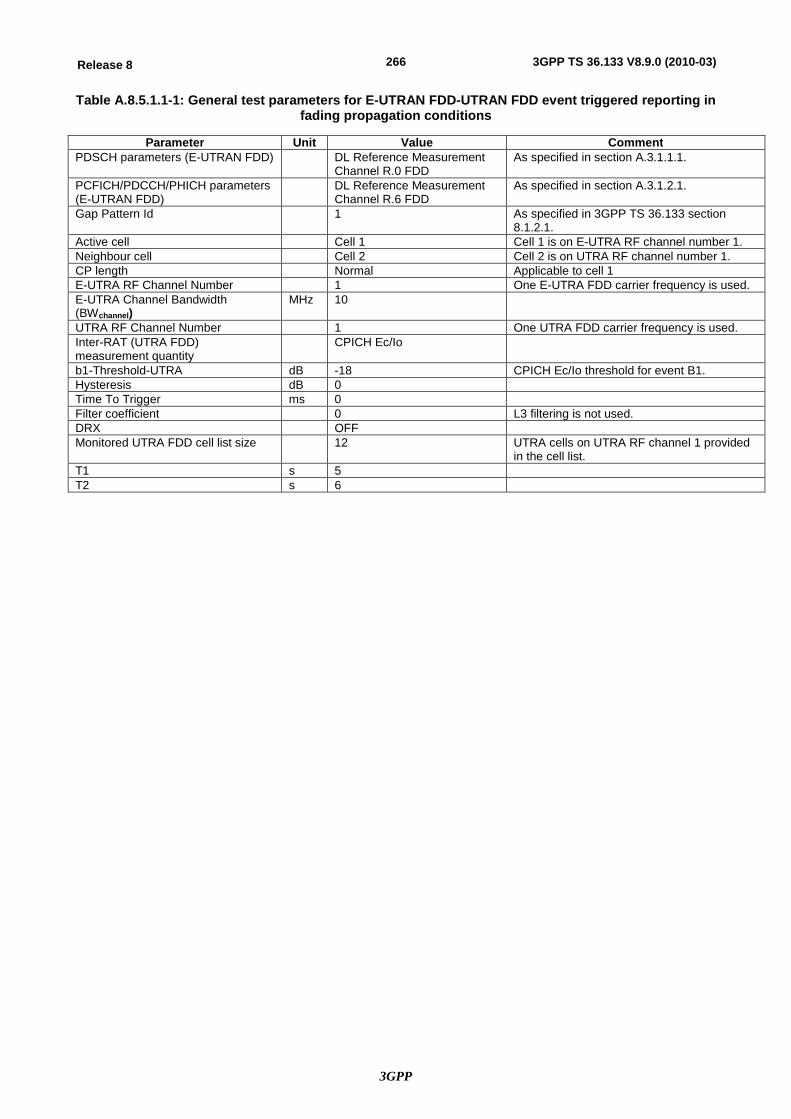
3GPP
266Release 8 3GPP TS 36.133 V8.9.0 (2010-03)
Table A.8.5.1.1-1: General test parameters for E-UTRAN FDD-UTRAN FDD event triggered reporting in fading propagation conditions
Parameter Unit Value Comment PDSCH parameters (E-UTRAN FDD) DL Reference Measurement
Channel R.0 FDD As specified in section A.3.1.1.1.
PCFICH/PDCCH/PHICH parameters (E-UTRAN FDD)
DL Reference Measurement Channel R.6 FDD
As specified in section A.3.1.2.1.
Gap Pattern Id 1 As specified in 3GPP TS 36.133 section 8.1.2.1.
Active cell Cell 1 Cell 1 is on E-UTRA RF channel number 1. Neighbour cell Cell 2 Cell 2 is on UTRA RF channel number 1. CP length Normal Applicable to cell 1 E-UTRA RF Channel Number 1 One E-UTRA FDD carrier frequency is used. E-UTRA Channel Bandwidth (BWchannel)
MHz 10
UTRA RF Channel Number 1 One UTRA FDD carrier frequency is used. Inter-RAT (UTRA FDD) measurement quantity
CPICH Ec/Io
b1-Threshold-UTRA dB -18 CPICH Ec/Io threshold for event B1. Hysteresis dB 0 Time To Trigger ms 0 Filter coefficient 0 L3 filtering is not used. DRX OFF Monitored UTRA FDD cell list size 12 UTRA cells on UTRA RF channel 1 provided
in the cell list. T1 s 5 T2 s 6

3GPP
267Release 8 3GPP TS 36.133 V8.9.0 (2010-03)
Table A.8.5.1.1-2: Cell specific test parameters for E-UTRAN FDD (cell # 1) for event triggered reporting of UTRAN FDD cell under fading propagation conditions
Parameter Unit Cell 1 T1 T2
E-UTRA RF Channel Number 1 BWchannel MHz 10 OCNG Pattern defined in A.3.2.1.1 (OP.1 FDD)
OP.1 FDD
PBCH_RA dB
0
PBCH_RB dB PSS_RA dB SSS_RA dB PCFICH_RB dB PHICH_RA dB PHICH_RB dB PDCCH_RA dB PDCCH_RB dB PDSCH_RA dB PDSCH_RB dB OCNG_RANote 1 dB OCNG_RBNote 1 dB
ots IÊ dB 4 4
ocs NÊ dB 4 4
ocN dBm/15 kHz -98
RSRP dBm/15 kHz -94 -94 SCH_RP dBm/15 kHz -94 -94 Propagation Condition ETU70 Note 1: OCNG shall be used such that both cells are fully allocated and a constant total transmitted power
spectral density is achieved for all OFDM symbols. Note 2: The resources for uplink transmission are assigned to the UE prior to the start of time period T2.
Table A.8.5.1.1-3: Cell specific test parameters for UTRAN FDD (cell # 2) for event triggered reporting of UTRAN FDD cell under fading propagation conditions
Parameter Unit Cell 2
T1 T2 UTRA RF Channel Number 1 CPICH_Ec/Ior dB -10 PCCPCH_Ec/Ior dB -12 SCH_Ec/Ior dB -12 PICH_Ec/Ior dB -15 DPCH_Ec/Ior dB N/A OCNS -0.941
ocor II dB -Infinity -1.8
ocI dBm/3.84 MHz -70
CPICH_Ec/Io dB -Infinity -14 Propagation Condition Case 5 (Note 3) Note 1: The DPCH level is controlled by the power control loop. Note 2: The power of the OCNS channel that is added shall make the total power from the cell to be equal
to Ior.
Note 3: Case 5 propagation conditions are defined in Annex A of 3GPP TS 25.101.
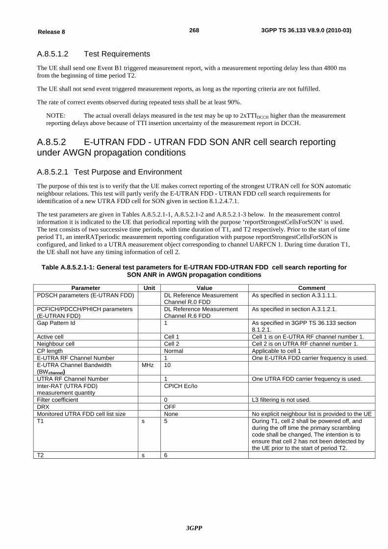
3GPP
268Release 8 3GPP TS 36.133 V8.9.0 (2010-03)
A.8.5.1.2 Test Requirements
The UE shall send one Event B1 triggered measurement report, with a measurement reporting delay less than 4800 ms from the beginning of time period T2.
The UE shall not send event triggered measurement reports, as long as the reporting criteria are not fulfilled.
The rate of correct events observed during repeated tests shall be at least 90%.
NOTE: The actual overall delays measured in the test may be up to 2xTTIDCCH higher than the measurement reporting delays above because of TTI insertion uncertainty of the measurement report in DCCH.
A.8.5.2 E-UTRAN FDD - UTRAN FDD SON ANR cell search reporting under AWGN propagation conditions
A.8.5.2.1 Test Purpose and Environment
The purpose of this test is to verify that the UE makes correct reporting of the strongest UTRAN cell for SON automatic neighbour relations. This test will partly verify the E-UTRAN FDD - UTRAN FDD cell search requirements for identification of a new UTRA FDD cell for SON given in section 8.1.2.4.7.1.
The test parameters are given in Tables A.8.5.2.1-1, A.8.5.2.1-2 and A.8.5.2.1-3 below. In the measurement control information it is indicated to the UE that periodical reporting with the purpose ‘reportStrongestCellsForSON’ is used. The test consists of two successive time periods, with time duration of T1, and T2 respectively. Prior to the start of time period T1, an interRATperiodic measurement reporting configuration with purpose reportStrongestCellsForSON is configured, and linked to a UTRA measurement object corresponding to channel UARFCN 1. During time duration T1, the UE shall not have any timing information of cell 2.
Table A.8.5.2.1-1: General test parameters for E-UTRAN FDD-UTRAN FDD cell search reporting for SON ANR in AWGN propagation conditions
Parameter Unit Value Comment PDSCH parameters (E-UTRAN FDD) DL Reference Measurement
Channel R.0 FDD As specified in section A.3.1.1.1.
PCFICH/PDCCH/PHICH parameters (E-UTRAN FDD)
DL Reference Measurement Channel R.6 FDD
As specified in section A.3.1.2.1.
Gap Pattern Id 1 As specified in 3GPP TS 36.133 section 8.1.2.1.
Active cell Cell 1 Cell 1 is on E-UTRA RF channel number 1. Neighbour cell Cell 2 Cell 2 is on UTRA RF channel number 1. CP length Normal Applicable to cell 1 E-UTRA RF Channel Number 1 One E-UTRA FDD carrier frequency is used. E-UTRA Channel Bandwidth (BWchannel)
MHz 10
UTRA RF Channel Number 1 One UTRA FDD carrier frequency is used. Inter-RAT (UTRA FDD) measurement quantity
CPICH Ec/Io
Filter coefficient 0 L3 filtering is not used. DRX OFF Monitored UTRA FDD cell list size None No explicit neighbour list is provided to the UE T1 s 5 During T1, cell 2 shall be powered off, and
during the off time the primary scrambling code shall be changed, The intention is to ensure that cell 2 has not been detected by the UE prior to the start of period T2.
T2 s 6
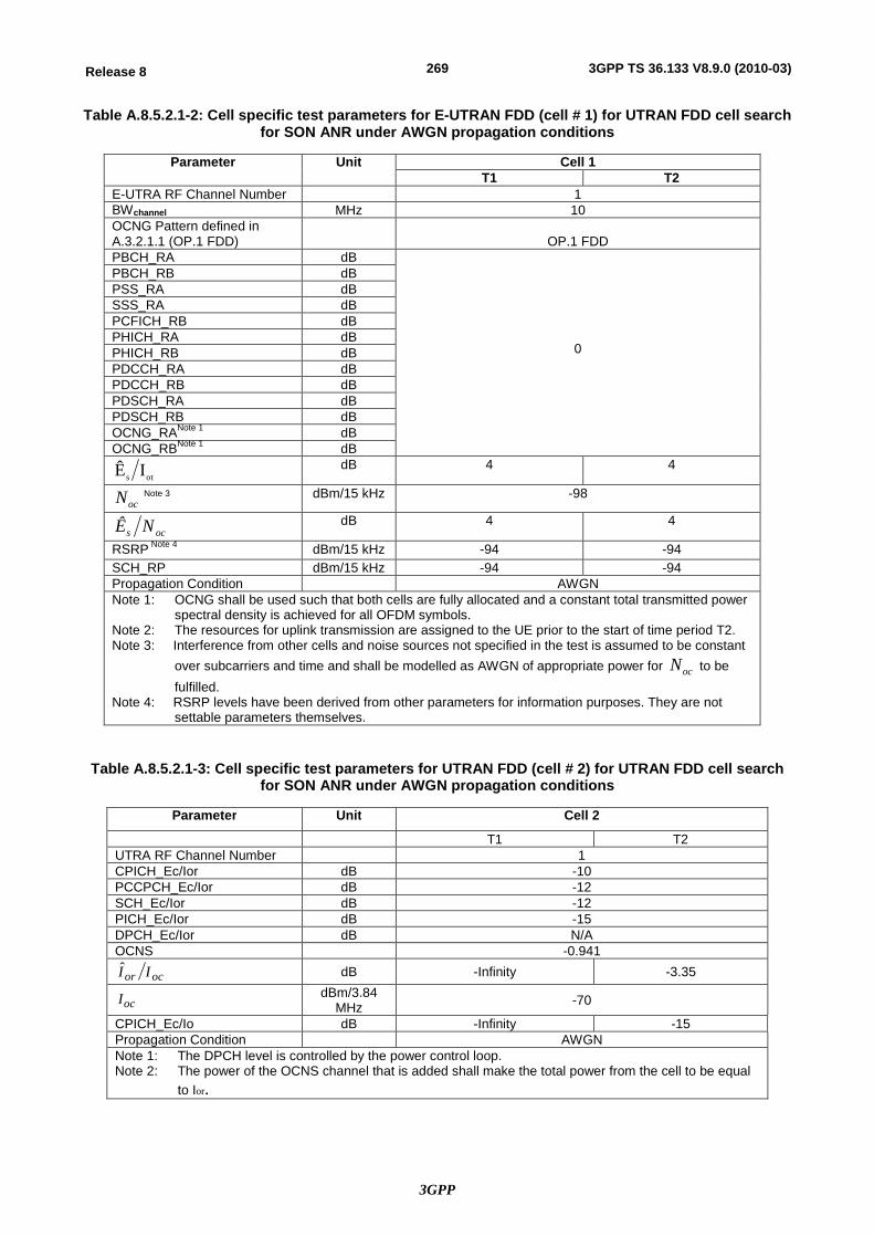
3GPP
269Release 8 3GPP TS 36.133 V8.9.0 (2010-03)
Table A.8.5.2.1-2: Cell specific test parameters for E-UTRAN FDD (cell # 1) for UTRAN FDD cell search for SON ANR under AWGN propagation conditions
Parameter Unit Cell 1 T1 T2
E-UTRA RF Channel Number 1 BWchannel MHz 10 OCNG Pattern defined in A.3.2.1.1 (OP.1 FDD)
OP.1 FDD
PBCH_RA dB
0
PBCH_RB dB PSS_RA dB SSS_RA dB PCFICH_RB dB PHICH_RA dB PHICH_RB dB PDCCH_RA dB PDCCH_RB dB PDSCH_RA dB PDSCH_RB dB OCNG_RANote 1 dB OCNG_RBNote 1 dB
ots IÊ dB 4 4
ocN Note 3 dBm/15 kHz -98
ocs NÊ dB 4 4
RSRP Note 4 dBm/15 kHz -94 -94 SCH_RP dBm/15 kHz -94 -94 Propagation Condition AWGN Note 1: OCNG shall be used such that both cells are fully allocated and a constant total transmitted power
spectral density is achieved for all OFDM symbols. Note 2: The resources for uplink transmission are assigned to the UE prior to the start of time period T2. Note 3: Interference from other cells and noise sources not specified in the test is assumed to be constant
over subcarriers and time and shall be modelled as AWGN of appropriate power for ocN to be fulfilled.
Note 4: RSRP levels have been derived from other parameters for information purposes. They are not settable parameters themselves.
Table A.8.5.2.1-3: Cell specific test parameters for UTRAN FDD (cell # 2) for UTRAN FDD cell search for SON ANR under AWGN propagation conditions
Parameter Unit Cell 2
T1 T2 UTRA RF Channel Number 1 CPICH_Ec/Ior dB -10 PCCPCH_Ec/Ior dB -12 SCH_Ec/Ior dB -12 PICH_Ec/Ior dB -15 DPCH_Ec/Ior dB N/A OCNS -0.941
ocor II dB -Infinity -3.35
ocI dBm/3.84 MHz -70
CPICH_Ec/Io dB -Infinity -15 Propagation Condition AWGN Note 1: The DPCH level is controlled by the power control loop. Note 2: The power of the OCNS channel that is added shall make the total power from the cell to be equal
to Ior.
3GPP
270Release 8 3GPP TS 36.133 V8.9.0 (2010-03)
A.8.5.2.2 Test Requirements
The UE shall send the first measurement report containing the primary scrambling code of cell 2, with a measurement reporting delay less than 4800 ms from the beginning of time period T2.
The rate of correct measurement reports observed with this delay during repeated tests shall be at least 90%.
NOTE: The actual overall delays measured in the test may be up to 2xTTIDCCH higher than the measurement reporting delays above because of TTI insertion uncertainty of the measurement report in DCCH.
A.8.5.3 E-UTRAN FDD-UTRAN FDD event triggered reporting when DRX is used under fading propagation conditions
A.8.5.3.1 Test Purpose and Environment
The purpose of these tests is to verify that the UE makes correct reporting of an event in DRX. These tests will partly verify the E-UTRAN FDD-UTRAN FDD cell search requirements when DRX is used in section 8.1.2.4.1.2.
In these tests, there are two cells, one E-UTRAN cell and one UTRAN cell, and gap pattern configuration # 0 as defined in Table 8.1.2.1-1 is provided.
The common test parameters are given in Table A.8.5.3.1-1. Cell specific test parameters are given in Table A.8.5.3.1-2 for E-UTRAN and in Table A.8.5.3.1-5 for UTRAN. DRX configuration for Test1 and Test2 are given in Table A.8.5.2.1-3 and time alignment timer and scheduling request related parameters in Table A.8.5.2.1-4.
In Test 1 UE needs to be provided at least once every 500ms with new Timing Advance Command MAC control element to restart the Time aligment timer to keep UE uplink time alignment. Furhtermore UE is allocated with PUSCH resource at every DRX cycle. In Test 2 the uplink time alignment is not maintained and UE needs to use RACH to obtain UL allocation for measurement reporting.
In the measurement control information, it is indicated to the UE that event-triggered reporting with Event B1 is used. The tests consist of two successive time periods, with time duration of T1, and T2 respectively. During time duration T1, the UE shall not have any timing information of cell 2.
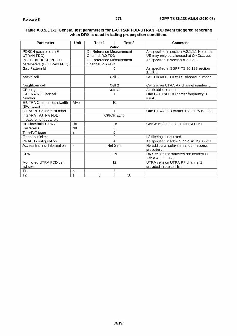
3GPP
271Release 8 3GPP TS 36.133 V8.9.0 (2010-03)
Table A.8.5.3.1-1: General test parameters for E-UTRAN FDD-UTRAN FDD event triggered reporting when DRX is used in fading propagation conditions
Parameter Unit Test 1 Test 2 Comment Value
PDSCH parameters (E-UTRAN FDD)
DL Reference Measurement Channel R.0 FDD
As specified in section A.3.1.1.1 Note that UE may only be allocated at On Duration
PCFICH/PDCCH/PHICH parameters (E-UTRAN FDD)
DL Reference Measurement Channel R.6 FDD
As specified in section A.3.1.2.1.
Gap Pattern Id 0 As specified in 3GPP TS 36.133 section 8.1.2.1.
Active cell Cell 1 Cell 1 is on E-UTRA RF channel number 1.
Neighbour cell Cell 2 Cell 2 is on UTRA RF channel number 1. CP length Normal Applicable to cell 1 E-UTRA RF Channel Number
1 One E-UTRA FDD carrier frequency is used.
E-UTRA Channel Bandwidth (BWchannel)
MHz 10
UTRA RF Channel Number 1 One UTRA FDD carrier frequency is used. Inter-RAT (UTRA FDD) measurement quantity
CPICH Ec/Io
b1-Threshold-UTRA dB -18 CPICH Ec/Io threshold for event B1. Hysteresis dB 0 TimeToTrigger s 0 Filter coefficient 0 L3 filtering is not used PRACH configuration 4 As specified in table 5.7.1-2 in TS 36.211 Access Barring Information - Not Sent No additional delays in random access
procedure. DRX ON DRX related parameters are defined in
Table A.8.5.3.1-3 Monitored UTRA FDD cell list size
12 UTRA cells on UTRA RF channel 1 provided in the cell list.
T1 s 5 T2 s 6 30
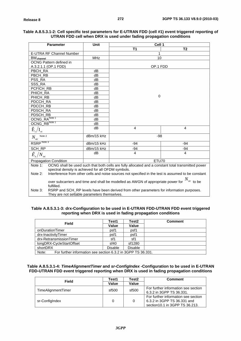
3GPP
272Release 8 3GPP TS 36.133 V8.9.0 (2010-03)
Table A.8.5.3.1-2: Cell specific test parameters for E-UTRAN FDD (cell #1) event triggered reporting of UTRAN FDD cell when DRX is used under fading propagation conditions
Parameter Unit Cell 1 T1 T2
E-UTRA RF Channel Number 1 BWchannel MHz 10 OCNG Pattern defined in A.3.2.1.1 (OP.1 FDD)
OP.1 FDD
PBCH_RA dB
0
PBCH_RB dB PSS_RA dB SSS_RA dB PCFICH_RB dB PHICH_RA dB PHICH_RB dB PDCCH_RA dB PDCCH_RB dB PDSCH_RA dB PDSCH_RB dB OCNG_RANote 1 dB OCNG_RBNote 1 dB
ots IÊ dB 4 4
ocN Note 2 dBm/15 kHz -98
RSRP Note 3 dBm/15 kHz -94 -94 SCH_RP dBm/15 kHz -94 -94
ocs NÊ dB 4 4
Propagation Condition ETU70 Note 1: OCNG shall be used such that both cells are fully allocated and a constant total transmitted power
spectral density is achieved for all OFDM symbols. Note 2: Interference from other cells and noise sources not specified in the test is assumed to be constant
over subcarriers and time and shall be modelled as AWGN of appropriate power for ocN to be
fulfilled. Note 3: RSRP and SCH_RP levels have been derived from other parameters for information purposes.
They are not settable parameters themselves.
Table A.8.5.3.1-3: drx-Configuration to be used in E-UTRAN FDD-UTRAN FDD event triggered reporting when DRX is used in fading propagation conditions
Field Test1 Test2 Comment Value Value
onDurationTimer psf1 psf1 drx-InactivityTimer psf1 psf1 drx-RetransmissionTimer sf1 sf1 longDRX-CycleStartOffset sf40 sf1280 shortDRX Disable Disable Note: For further information see section 6.3.2 in 3GPP TS 36.331.
Table A.8.5.3.1-4: TimeAlignmentTimer and sr-ConfigIndex -Configuration to be used in E-UTRAN FDD-UTRAN FDD event triggered reporting when DRX is used in fading propagation conditions
Field Test1 Test2 Comment Value Value
TimeAlignmentTimer sf500 sf500 For further information see section 6.3.2 in 3GPP TS 36.331.
sr-ConfigIndex 0 0 For further information see section 6.3.2 in 3GPP TS 36.331 and section10.1 in 3GPP TS 36.213.
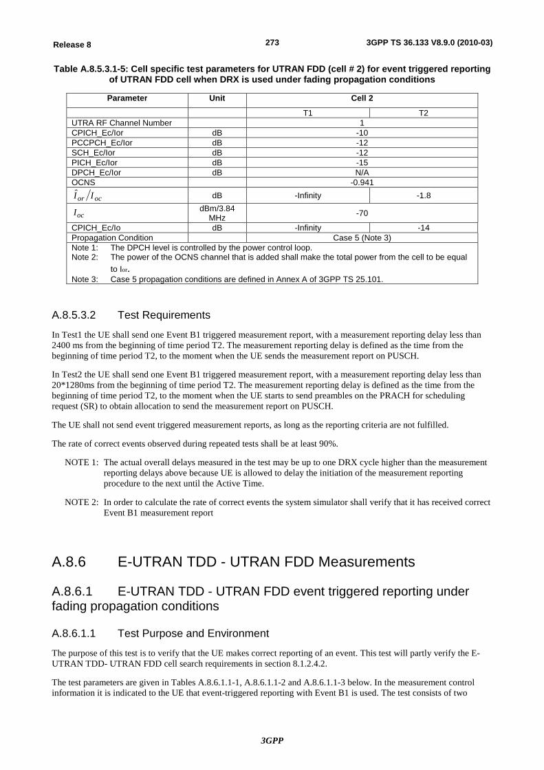
3GPP
273Release 8 3GPP TS 36.133 V8.9.0 (2010-03)
Table A.8.5.3.1-5: Cell specific test parameters for UTRAN FDD (cell # 2) for event triggered reporting of UTRAN FDD cell when DRX is used under fading propagation conditions
Parameter Unit Cell 2
T1 T2 UTRA RF Channel Number 1 CPICH_Ec/Ior dB -10 PCCPCH_Ec/Ior dB -12 SCH_Ec/Ior dB -12 PICH_Ec/Ior dB -15 DPCH_Ec/Ior dB N/A OCNS -0.941
ocor II dB -Infinity -1.8
ocI dBm/3.84 MHz -70
CPICH_Ec/Io dB -Infinity -14 Propagation Condition Case 5 (Note 3) Note 1: The DPCH level is controlled by the power control loop. Note 2: The power of the OCNS channel that is added shall make the total power from the cell to be equal
to Ior.
Note 3: Case 5 propagation conditions are defined in Annex A of 3GPP TS 25.101.
A.8.5.3.2 Test Requirements
In Test1 the UE shall send one Event B1 triggered measurement report, with a measurement reporting delay less than 2400 ms from the beginning of time period T2. The measurement reporting delay is defined as the time from the beginning of time period T2, to the moment when the UE sends the measurement report on PUSCH.
In Test2 the UE shall send one Event B1 triggered measurement report, with a measurement reporting delay less than 20*1280ms from the beginning of time period T2. The measurement reporting delay is defined as the time from the beginning of time period T2, to the moment when the UE starts to send preambles on the PRACH for scheduling request (SR) to obtain allocation to send the measurement report on PUSCH.
The UE shall not send event triggered measurement reports, as long as the reporting criteria are not fulfilled.
The rate of correct events observed during repeated tests shall be at least 90%.
NOTE 1: The actual overall delays measured in the test may be up to one DRX cycle higher than the measurement reporting delays above because UE is allowed to delay the initiation of the measurement reporting procedure to the next until the Active Time.
NOTE 2: In order to calculate the rate of correct events the system simulator shall verify that it has received correct Event B1 measurement report
A.8.6 E-UTRAN TDD - UTRAN FDD Measurements
A.8.6.1 E-UTRAN TDD - UTRAN FDD event triggered reporting under fading propagation conditions
A.8.6.1.1 Test Purpose and Environment
The purpose of this test is to verify that the UE makes correct reporting of an event. This test will partly verify the E-UTRAN TDD- UTRAN FDD cell search requirements in section 8.1.2.4.2.
The test parameters are given in Tables A.8.6.1.1-1, A.8.6.1.1-2 and A.8.6.1.1-3 below. In the measurement control information it is indicated to the UE that event-triggered reporting with Event B1 is used. The test consists of two
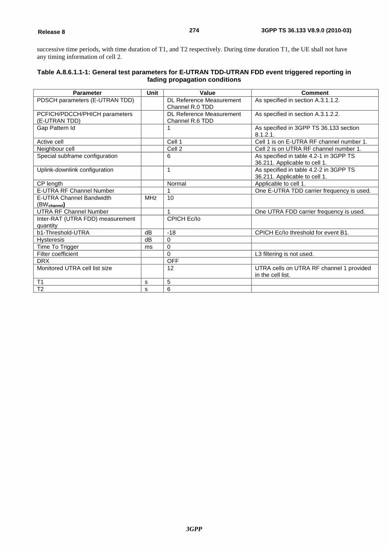
3GPP
274Release 8 3GPP TS 36.133 V8.9.0 (2010-03)
successive time periods, with time duration of T1, and T2 respectively. During time duration T1, the UE shall not have any timing information of cell 2.
Table A.8.6.1.1-1: General test parameters for E-UTRAN TDD-UTRAN FDD event triggered reporting in fading propagation conditions
Parameter Unit Value Comment PDSCH parameters (E-UTRAN TDD) DL Reference Measurement
Channel R.0 TDD As specified in section A.3.1.1.2.
PCFICH/PDCCH/PHICH parameters (E-UTRAN TDD)
DL Reference Measurement Channel R.6 TDD
As specified in section A.3.1.2.2.
Gap Pattern Id 1 As specified in 3GPP TS 36.133 section 8.1.2.1.
Active cell Cell 1 Cell 1 is on E-UTRA RF channel number 1. Neighbour cell Cell 2 Cell 2 is on UTRA RF channel number 1. Special subframe configuration 6 As specified in table 4.2-1 in 3GPP TS
36.211. Applicable to cell 1. Uplink-downlink configuration 1 As specified in table 4.2-2 in 3GPP TS
36.211. Applicable to cell 1. CP length Normal Applicable to cell 1. E-UTRA RF Channel Number 1 One E-UTRA TDD carrier frequency is used. E-UTRA Channel Bandwidth (BWchannel)
MHz 10
UTRA RF Channel Number 1 One UTRA FDD carrier frequency is used. Inter-RAT (UTRA FDD) measurement quantity
CPICH Ec/Io
b1-Threshold-UTRA dB -18 CPICH Ec/Io threshold for event B1. Hysteresis dB 0 Time To Trigger ms 0 Filter coefficient 0 L3 filtering is not used. DRX OFF Monitored UTRA cell list size 12 UTRA cells on UTRA RF channel 1 provided
in the cell list. T1 s 5 T2 s 6
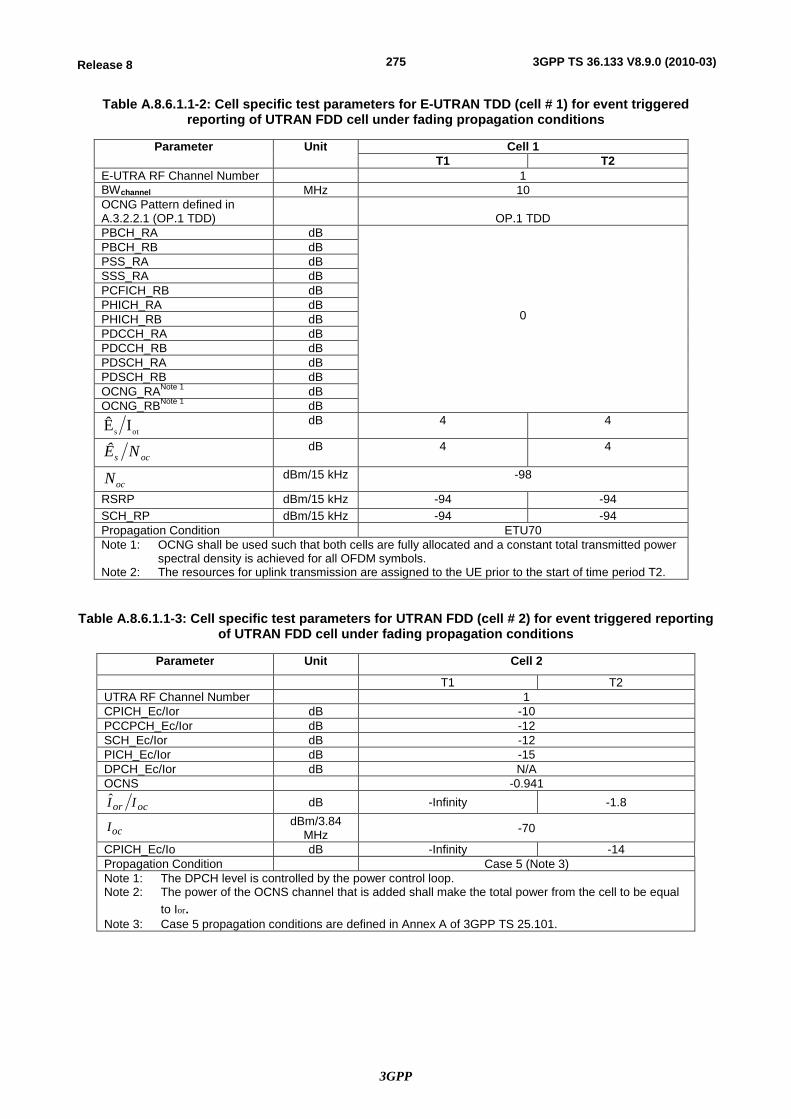
3GPP
275Release 8 3GPP TS 36.133 V8.9.0 (2010-03)
Table A.8.6.1.1-2: Cell specific test parameters for E-UTRAN TDD (cell # 1) for event triggered reporting of UTRAN FDD cell under fading propagation conditions
Parameter Unit Cell 1 T1 T2
E-UTRA RF Channel Number 1 BWchannel MHz 10 OCNG Pattern defined in A.3.2.2.1 (OP.1 TDD)
OP.1 TDD
PBCH_RA dB
0
PBCH_RB dB PSS_RA dB SSS_RA dB PCFICH_RB dB PHICH_RA dB PHICH_RB dB PDCCH_RA dB PDCCH_RB dB PDSCH_RA dB PDSCH_RB dB OCNG_RANote 1 dB OCNG_RBNote 1 dB
ots IÊ dB 4 4
ocs NÊ dB 4 4
ocN dBm/15 kHz -98
RSRP dBm/15 kHz -94 -94 SCH_RP dBm/15 kHz -94 -94 Propagation Condition ETU70 Note 1: OCNG shall be used such that both cells are fully allocated and a constant total transmitted power
spectral density is achieved for all OFDM symbols. Note 2: The resources for uplink transmission are assigned to the UE prior to the start of time period T2.
Table A.8.6.1.1-3: Cell specific test parameters for UTRAN FDD (cell # 2) for event triggered reporting of UTRAN FDD cell under fading propagation conditions
Parameter Unit Cell 2
T1 T2 UTRA RF Channel Number 1 CPICH_Ec/Ior dB -10 PCCPCH_Ec/Ior dB -12 SCH_Ec/Ior dB -12 PICH_Ec/Ior dB -15 DPCH_Ec/Ior dB N/A OCNS -0.941
ocor II dB -Infinity -1.8
ocI dBm/3.84 MHz -70
CPICH_Ec/Io dB -Infinity -14 Propagation Condition Case 5 (Note 3) Note 1: The DPCH level is controlled by the power control loop. Note 2: The power of the OCNS channel that is added shall make the total power from the cell to be equal
to Ior.
Note 3: Case 5 propagation conditions are defined in Annex A of 3GPP TS 25.101.
3GPP
276Release 8 3GPP TS 36.133 V8.9.0 (2010-03)
A.8.6.1.2 Test Requirements
The UE shall send one Event B1 triggered measurement report, with a measurement reporting delay less than 4800 ms from the beginning of time period T2.
The UE shall not send event triggered measurement reports, as long as the reporting criteria are not fulfilled.
The rate of correct events observed during repeated tests shall be at least 90%.
NOTE: The actual overall delays measured in the test may be up to 2xTTIDCCH higher than the measurement reporting delays above because of TTI insertion uncertainty of the measurement report in DCCH.
A.8.7 E-UTRAN TDD – UTRAN TDD Measurements
A.8.7.1 E-UTRAN TDD to UTRAN TDD cell search under fading propagation conditions
A.8.7.1.1 Test Purpose and Environment
A.8.7.1.1.1 3.84 Mcps TDD option
A.8.7.1.1.2 1.28 Mcps TDD option
The purpose of this test is to verify that the UE makes correct reporting of an event. This test will partly verify the E-UTRA TDD to UTRA TDD cell search requirements in section 8.1.2.4.3 under fading propagation conditions.
This test scenario comprised of 1 E-UTRA TDD serving cell, and 1 UTRA TDD cell to be searched. Test parameters are given in Table A.8.7.1.1.2-1, A.8.7.1.1.2-2, and A.8.7.1.1.2-3. Gap pattern configuration #0 as defined in table 8.1.2.1-1 is provided.
In the measurement control information, it is indicated to the UE that event-triggered reporting with Event B1 is used. The test consists of two successive time periods, with time duration of T1 and T2 respectively. During time duration T1, the UE shall not have any timing information of cell 2.
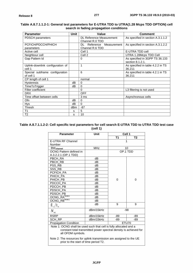
3GPP
277Release 8 3GPP TS 36.133 V8.9.0 (2010-03)
Table A.8.7.1.1.2-1: General test parameters for E-UTRA TDD to UTRA(1.28 Mcps TDD OPTION) cell search in fading propagation conditions
Parameter Unit Value Comment PDSCH parameters DL Reference Measurement
Channel R.0 TDD As specified in section A.3.1.1.2
PCFICH/PDCCH/PHICH parameters
DL Reference Measurement Channel R.6 TDD
As specified in section A.3.1.2.2
Active cell Cell 1 E-UTRA TDD cell Neighbour cell Cell 2 UTRA 1.28Mcps TDD Cell Gap Pattern Id 0 As specified in 3GPP TS 36.133
section 8.1.2.1. Uplink-downlink configuration of cell 1
1 As specified in table 4.2.2 in TS 36.211
Special subframe configuration of cell 1
6 As specified in table 4.2.1 in TS 36.211
CP length of cell 1 normal Hysteresis dB 0 TimeToTrigger dB 0 Filter coefficient 0 L3 filtering is not used DRX OFF Time offset between cells 3 ms Asynchronous cells Ofn dB 0 Hys dB 0 Thresh dBm -87 T1 s 5 T2 s 10
Table A.8.7.1.1.2-2: Cell specific test parameters for cell search E-UTRA TDD to UTRA TDD test case (cell 1)
Parameter Unit Cell 1 T1 T2
E-UTRA RF Channel Number
1
BWchannel MHz 10 OCNG Pattern defined in A.3.2.2.1 (OP.1 TDD)
OP.1 TDD
PBCH_RA dB
0 0
PBCH_RB dB PSS_RB dB SSS_RB dB PCFICH_PA dB PHICH_PA dB PHICH_PB dB PDCCH_PA dB PDCCH_PB dB PDSCH_PA dB PDSCH_PB dB OCNG_RANote1 dB OCNG_RBNote1 dB
ots IÊ dB 9 9
ocN dBm/15kHz -98
RSRP dBm/15kHz -89 -89 SCH_RP dBm/15kHz -89 -89 Propagation Condition ETU70 Note 1: OCNG shall be used such that cell is fully allocated and a
constant total transmitted power spectral density is achieved for all OFDM symbols.
Note 2: The resources for uplink transmission are assigned to the UE prior to the start of time period T2.
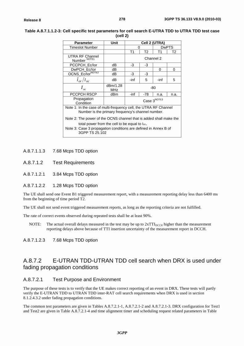
3GPP
278Release 8 3GPP TS 36.133 V8.9.0 (2010-03)
Table A.8.7.1.1.2-3: Cell specific test parameters for cell search E-UTRA TDD to UTRA TDD test case (cell 2)
Parameter Unit Cell 2 (UTRA) Timeslot Number 0 DwPTS
T1 T2 T1 T2 UTRA RF Channel
Number NOTE1 Channel 2
PCCPCH_Ec/Ior dB -3 -3 DwPCH_Ec/Ior dB 0 0
OCNS_Ec/IorNOTE2 dB -3 -3
ocor II dB -inf 5 -inf 5
ocI dBm/1.28 MHz -80
PCCPCH RSCP dBm -inf -78 n.a. n.a. Propagation
Condition Case 3NOTE3
Note 1: In the case of multi-frequency cell, the UTRA RF Channel Number is the primary frequency’s channel number.
Note 2: The power of the OCNS channel that is added shall make the total power from the cell to be equal to Ior.
Note 3: Case 3 propagation conditions are defined in Annex B of 3GPP TS 25.102
A.8.7.1.1.3 7.68 Mcps TDD option
A.8.7.1.2 Test Requirements
A.8.7.1.2.1 3.84 Mcps TDD option
A.8.7.1.2.2 1.28 Mcps TDD option
The UE shall send one Event B1 triggered measurement report, with a measurement reporting delay less than 6400 ms from the beginning of time period T2.
The UE shall not send event triggered measurement reports, as long as the reporting criteria are not fulfilled.
The rate of correct events observed during repeated tests shall be at least 90%.
NOTE: The actual overall delays measured in the test may be up to 2xTTIDCCH higher than the measurement reporting delays above because of TTI insertion uncertainty of the measurement report in DCCH.
A.8.7.1.2.3 7.68 Mcps TDD option
A.8.7.2 E-UTRAN TDD-UTRAN TDD cell search when DRX is used under fading propagation conditions
A.8.7.2.1 Test Purpose and Environment
The purpose of these tests is to verify that the UE makes correct reporting of an event in DRX. These tests will partly verify the E-UTRAN TDD to UTRAN TDD inter-RAT cell search requirements when DRX is used in section 8.1.2.4.3.2 under fading propagation conditions.
The common test parameters are given in Tables A.8.7.2.1-1, A.8.7.2.1-2 and A.8.7.2.1-3. DRX configuration for Test1 and Test2 are given in Table A.8.7.2.1-4 and time alignment timer and scheduling request related parameters in Table
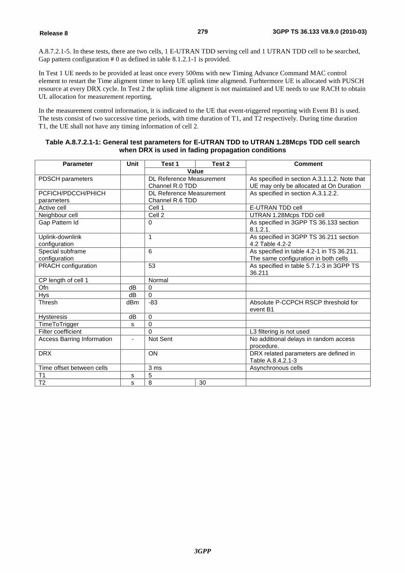
3GPP
279Release 8 3GPP TS 36.133 V8.9.0 (2010-03)
A.8.7.2.1-5. In these tests, there are two cells, 1 E-UTRAN TDD serving cell and 1 UTRAN TDD cell to be searched, Gap pattern configuration # 0 as defined in table 8.1.2.1-1 is provided.
In Test 1 UE needs to be provided at least once every 500ms with new Timing Advance Command MAC control element to restart the Time aligment timer to keep UE uplink time aligmend. Furhtermore UE is allocated with PUSCH resource at every DRX cycle. In Test 2 the uplink time aligment is not maintained and UE needs to use RACH to obtain UL allocation for measurement reporting.
In the measurement control information, it is indicated to the UE that event-triggered reporting with Event B1 is used. The tests consist of two successive time periods, with time duration of T1, and T2 respectively. During time duration T1, the UE shall not have any timing information of cell 2.
Table A.8.7.2.1-1: General test parameters for E-UTRAN TDD to UTRAN 1.28Mcps TDD cell search when DRX is used in fading propagation conditions
Parameter Unit Test 1 Test 2 Comment Value
PDSCH parameters DL Reference Measurement Channel R.0 TDD
As specified in section A.3.1.1.2. Note that UE may only be allocated at On Duration
PCFICH/PDCCH/PHICH parameters
DL Reference Measurement Channel R.6 TDD
As specified in section A.3.1.2.2.
Active cell Cell 1 E-UTRAN TDD cell Neighbour cell Cell 2 UTRAN 1.28Mcps TDD cell Gap Pattern Id 0 As specified in 3GPP TS 36.133 section
8.1.2.1. Uplink-downlink configuration
1 As specified in 3GPP TS 36.211 section 4.2 Table 4.2-2
Special subframe configuration
6 As specified in table 4.2-1 in TS 36.211. The same configuration in both cells
PRACH configuration 53 As specified in table 5.7.1-3 in 3GPP TS 36.211
CP length of cell 1 Normal Ofn dB 0 Hys dB 0 Thresh dBm -83 Absolute P-CCPCH RSCP threshold for
event B1 Hysteresis dB 0 TimeToTrigger s 0 Filter coefficient 0 L3 filtering is not used Access Barring Information - Not Sent No additional delays in random access
procedure. DRX ON DRX related parameters are defined in
Table A.8.4.2.1-3 Time offset between cells 3 ms Asynchronous cells T1 s 5 T2 s 8 30
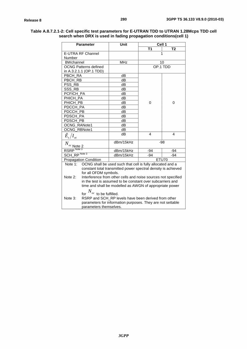
3GPP
280Release 8 3GPP TS 36.133 V8.9.0 (2010-03)
Table A.8.7.2.1-2: Cell specific test parameters for E-UTRAN TDD to UTRAN 1.28Mcps TDD cell search when DRX is used in fading propagation conditions(cell 1)
Parameter Unit Cell 1 T1 T2
E-UTRA RF Channel Number
1
BWchannel MHz 10 OCNG Patterns defined in A.3.2.1.1 (OP.1 TDD)
OP.1 TDD
PBCH_RA dB
0 0
PBCH_RB dB PSS_RB dB SSS_RB dB PCFICH_PA dB PHICH_PA dB PHICH_PB dB PDCCH_PA dB PDCCH_PB dB PDSCH_PA dB PDSCH_PB dB OCNG_RANote1 dB OCNG_RBNote1 dB
ots IÊ
dB 4 4
ocNNote 2
dBm/15kHz -98
RSRP Note 3 dBm/15kHz -94 -94 SCH_RP Note 3 dBm/15kHz -94 -94 Propagation Condition ETU70 Note 1: OCNG shall be used such that cell is fully allocated and a
constant total transmitted power spectral density is achieved for all OFDM symbols.
Note 2: Interference from other cells and noise sources not specified in the test is assumed to be constant over subcarriers and time and shall be modelled as AWGN of appropriate power
for ocN to be fulfilled.
Note 3: RSRP and SCH_RP levels have been derived from other parameters for information purposes. They are not settable parameters themselves.
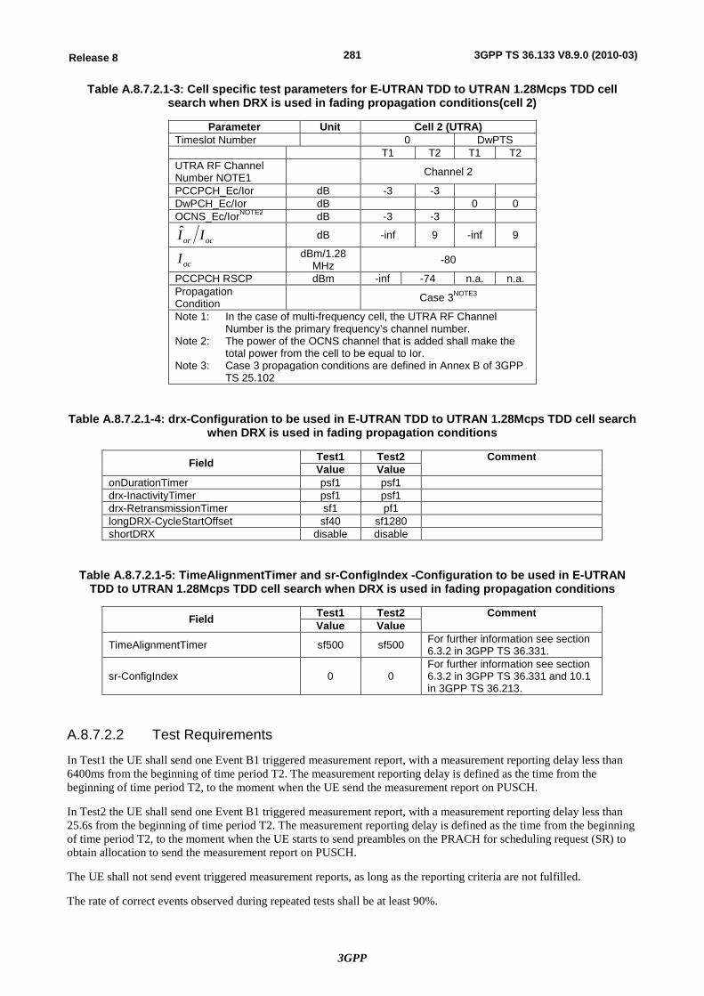
3GPP
281Release 8 3GPP TS 36.133 V8.9.0 (2010-03)
Table A.8.7.2.1-3: Cell specific test parameters for E-UTRAN TDD to UTRAN 1.28Mcps TDD cell search when DRX is used in fading propagation conditions(cell 2)
Parameter Unit Cell 2 (UTRA) Timeslot Number 0 DwPTS T1 T2 T1 T2 UTRA RF Channel Number NOTE1 Channel 2
PCCPCH_Ec/Ior dB -3 -3 DwPCH_Ec/Ior dB 0 0 OCNS_Ec/IorNOTE2 dB -3 -3
ocor II
dB -inf 9 -inf 9
ocI
dBm/1.28 MHz -80
PCCPCH RSCP dBm -inf -74 n.a. n.a. Propagation Condition Case 3NOTE3
Note 1: In the case of multi-frequency cell, the UTRA RF Channel Number is the primary frequency’s channel number.
Note 2: The power of the OCNS channel that is added shall make the total power from the cell to be equal to Ior.
Note 3: Case 3 propagation conditions are defined in Annex B of 3GPP TS 25.102
Table A.8.7.2.1-4: drx-Configuration to be used in E-UTRAN TDD to UTRAN 1.28Mcps TDD cell search when DRX is used in fading propagation conditions
Field Test1 Test2 Comment Value Value
onDurationTimer psf1 psf1 drx-InactivityTimer psf1 psf1 drx-RetransmissionTimer sf1 pf1 longDRX-CycleStartOffset sf40 sf1280 shortDRX disable disable
Table A.8.7.2.1-5: TimeAlignmentTimer and sr-ConfigIndex -Configuration to be used in E-UTRAN TDD to UTRAN 1.28Mcps TDD cell search when DRX is used in fading propagation conditions
Field Test1 Test2 Comment Value Value
TimeAlignmentTimer sf500 sf500 For further information see section 6.3.2 in 3GPP TS 36.331.
sr-ConfigIndex 0 0 For further information see section 6.3.2 in 3GPP TS 36.331 and 10.1 in 3GPP TS 36.213.
A.8.7.2.2 Test Requirements
In Test1 the UE shall send one Event B1 triggered measurement report, with a measurement reporting delay less than 6400ms from the beginning of time period T2. The measurement reporting delay is defined as the time from the beginning of time period T2, to the moment when the UE send the measurement report on PUSCH.
In Test2 the UE shall send one Event B1 triggered measurement report, with a measurement reporting delay less than 25.6s from the beginning of time period T2. The measurement reporting delay is defined as the time from the beginning of time period T2, to the moment when the UE starts to send preambles on the PRACH for scheduling request (SR) to obtain allocation to send the measurement report on PUSCH.
The UE shall not send event triggered measurement reports, as long as the reporting criteria are not fulfilled.
The rate of correct events observed during repeated tests shall be at least 90%.
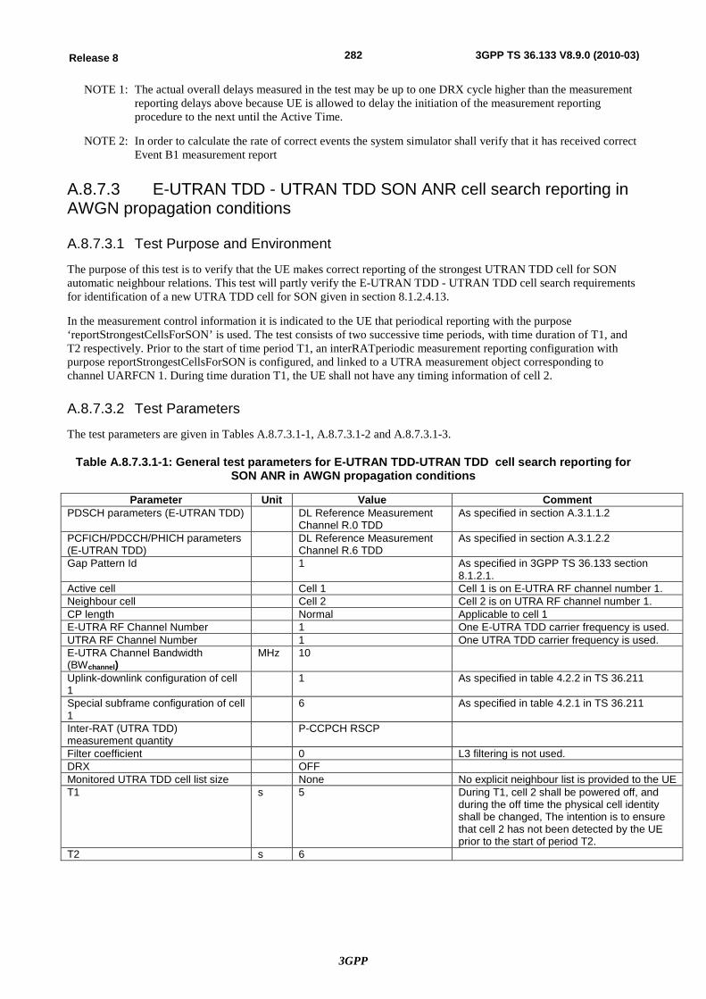
3GPP
282Release 8 3GPP TS 36.133 V8.9.0 (2010-03)
NOTE 1: The actual overall delays measured in the test may be up to one DRX cycle higher than the measurement reporting delays above because UE is allowed to delay the initiation of the measurement reporting procedure to the next until the Active Time.
NOTE 2: In order to calculate the rate of correct events the system simulator shall verify that it has received correct Event B1 measurement report
A.8.7.3 E-UTRAN TDD - UTRAN TDD SON ANR cell search reporting in AWGN propagation conditions
A.8.7.3.1 Test Purpose and Environment
The purpose of this test is to verify that the UE makes correct reporting of the strongest UTRAN TDD cell for SON automatic neighbour relations. This test will partly verify the E-UTRAN TDD - UTRAN TDD cell search requirements for identification of a new UTRA TDD cell for SON given in section 8.1.2.4.13.
In the measurement control information it is indicated to the UE that periodical reporting with the purpose ‘reportStrongestCellsForSON’ is used. The test consists of two successive time periods, with time duration of T1, and T2 respectively. Prior to the start of time period T1, an interRATperiodic measurement reporting configuration with purpose reportStrongestCellsForSON is configured, and linked to a UTRA measurement object corresponding to channel UARFCN 1. During time duration T1, the UE shall not have any timing information of cell 2.
A.8.7.3.2 Test Parameters
The test parameters are given in Tables A.8.7.3.1-1, A.8.7.3.1-2 and A.8.7.3.1-3.
Table A.8.7.3.1-1: General test parameters for E-UTRAN TDD-UTRAN TDD cell search reporting for SON ANR in AWGN propagation conditions
Parameter Unit Value Comment PDSCH parameters (E-UTRAN TDD) DL Reference Measurement
Channel R.0 TDD As specified in section A.3.1.1.2
PCFICH/PDCCH/PHICH parameters (E-UTRAN TDD)
DL Reference Measurement Channel R.6 TDD
As specified in section A.3.1.2.2
Gap Pattern Id 1 As specified in 3GPP TS 36.133 section 8.1.2.1.
Active cell Cell 1 Cell 1 is on E-UTRA RF channel number 1. Neighbour cell Cell 2 Cell 2 is on UTRA RF channel number 1. CP length Normal Applicable to cell 1 E-UTRA RF Channel Number 1 One E-UTRA TDD carrier frequency is used. UTRA RF Channel Number 1 One UTRA TDD carrier frequency is used. E-UTRA Channel Bandwidth (BWchannel)
MHz 10
Uplink-downlink configuration of cell 1
1 As specified in table 4.2.2 in TS 36.211
Special subframe configuration of cell 1
6 As specified in table 4.2.1 in TS 36.211
Inter-RAT (UTRA TDD) measurement quantity
P-CCPCH RSCP
Filter coefficient 0 L3 filtering is not used. DRX OFF Monitored UTRA TDD cell list size None No explicit neighbour list is provided to the UE T1 s 5 During T1, cell 2 shall be powered off, and
during the off time the physical cell identity shall be changed, The intention is to ensure that cell 2 has not been detected by the UE prior to the start of period T2.
T2 s 6
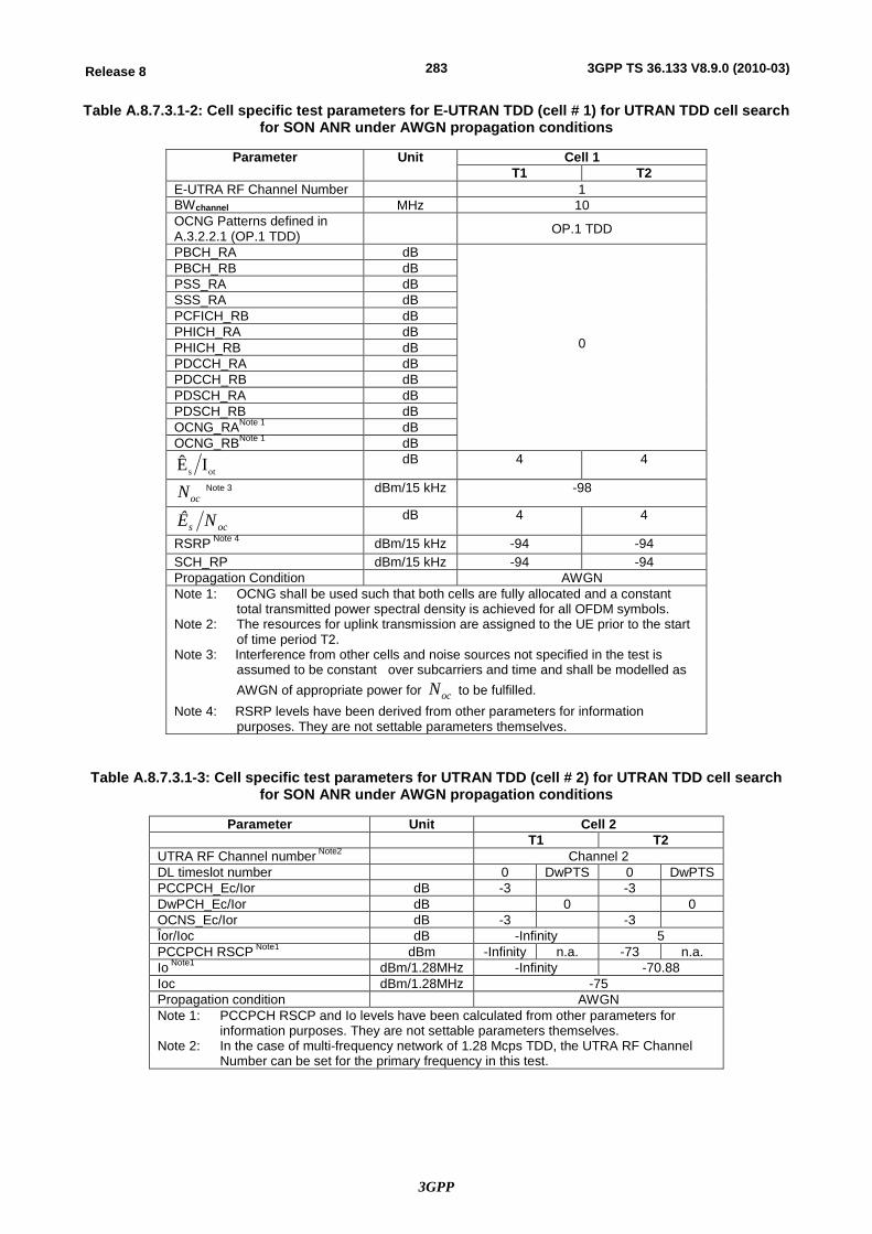
3GPP
283Release 8 3GPP TS 36.133 V8.9.0 (2010-03)
Table A.8.7.3.1-2: Cell specific test parameters for E-UTRAN TDD (cell # 1) for UTRAN TDD cell search for SON ANR under AWGN propagation conditions
Parameter Unit Cell 1 T1 T2
E-UTRA RF Channel Number 1 BWchannel MHz 10 OCNG Patterns defined in A.3.2.2.1 (OP.1 TDD) OP.1 TDD
PBCH_RA dB
0
PBCH_RB dB PSS_RA dB SSS_RA dB PCFICH_RB dB PHICH_RA dB PHICH_RB dB PDCCH_RA dB PDCCH_RB dB PDSCH_RA dB PDSCH_RB dB OCNG_RANote 1 dB OCNG_RBNote 1 dB
ots IÊ dB 4 4
ocN Note 3 dBm/15 kHz -98
ocs NÊ dB 4 4
RSRP Note 4 dBm/15 kHz -94 -94 SCH_RP dBm/15 kHz -94 -94 Propagation Condition AWGN Note 1: OCNG shall be used such that both cells are fully allocated and a constant
total transmitted power spectral density is achieved for all OFDM symbols. Note 2: The resources for uplink transmission are assigned to the UE prior to the start
of time period T2. Note 3: Interference from other cells and noise sources not specified in the test is
assumed to be constant over subcarriers and time and shall be modelled as AWGN of appropriate power for ocN to be fulfilled.
Note 4: RSRP levels have been derived from other parameters for information purposes. They are not settable parameters themselves.
Table A.8.7.3.1-3: Cell specific test parameters for UTRAN TDD (cell # 2) for UTRAN TDD cell search for SON ANR under AWGN propagation conditions
Parameter Unit Cell 2 T1 T2
UTRA RF Channel number Note2 Channel 2 DL timeslot number 0 DwPTS 0 DwPTS PCCPCH_Ec/Ior dB -3 -3 DwPCH_Ec/Ior dB 0 0 OCNS_Ec/Ior dB -3 -3 Îor/Ioc dB -Infinity 5 PCCPCH RSCP Note1 dBm -Infinity n.a. -73 n.a. Io Note1 dBm/1.28MHz -Infinity -70.88 Ioc dBm/1.28MHz -75 Propagation condition AWGN Note 1: PCCPCH RSCP and Io levels have been calculated from other parameters for
information purposes. They are not settable parameters themselves. Note 2: In the case of multi-frequency network of 1.28 Mcps TDD, the UTRA RF Channel
Number can be set for the primary frequency in this test.
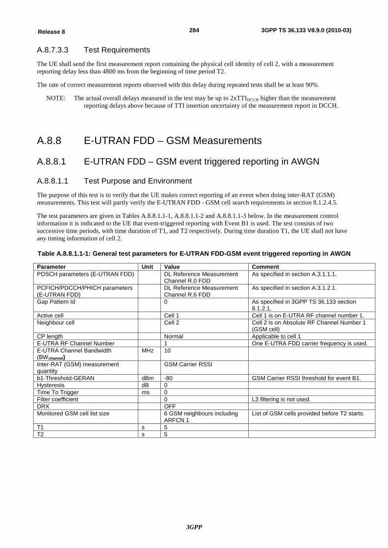
3GPP
284Release 8 3GPP TS 36.133 V8.9.0 (2010-03)
A.8.7.3.3 Test Requirements
The UE shall send the first measurement report containing the physical cell identity of cell 2, with a measurement reporting delay less than 4800 ms from the beginning of time period T2.
The rate of correct measurement reports observed with this delay during repeated tests shall be at least 90%.
NOTE: The actual overall delays measured in the test may be up to 2xTTIDCCH higher than the measurement reporting delays above because of TTI insertion uncertainty of the measurement report in DCCH.
A.8.8 E-UTRAN FDD – GSM Measurements
A.8.8.1 E-UTRAN FDD – GSM event triggered reporting in AWGN
A.8.8.1.1 Test Purpose and Environment
The purpose of this test is to verify that the UE makes correct reporting of an event when doing inter-RAT (GSM) measurements. This test will partly verify the E-UTRAN FDD - GSM cell search requirements in section 8.1.2.4.5.
The test parameters are given in Tables A.8.8.1.1-1, A.8.8.1.1-2 and A.8.8.1.1-3 below. In the measurement control information it is indicated to the UE that event-triggered reporting with Event B1 is used. The test consists of two successive time periods, with time duration of T1, and T2 respectively. During time duration T1, the UE shall not have any timing information of cell 2.
Table A.8.8.1.1-1: General test parameters for E-UTRAN FDD-GSM event triggered reporting in AWGN
Parameter Unit Value Comment PDSCH parameters (E-UTRAN FDD) DL Reference Measurement
Channel R.0 FDD As specified in section A.3.1.1.1.
PCFICH/PDCCH/PHICH parameters (E-UTRAN FDD)
DL Reference Measurement Channel R.6 FDD
As specified in section A.3.1.2.1.
Gap Pattern Id 0 As specified in 3GPP TS 36.133 section 8.1.2.1.
Active cell Cell 1 Cell 1 is on E-UTRA RF channel number 1. Neighbour cell Cell 2 Cell 2 is on Absolute RF Channel Number 1
(GSM cell) CP length Normal Applicable to cell 1 E-UTRA RF Channel Number 1 One E-UTRA FDD carrier frequency is used. E-UTRA Channel Bandwidth (BWchannel)
MHz 10
Inter-RAT (GSM) measurement quantity
GSM Carrier RSSI
b1-Threshold-GERAN dBm -80 GSM Carrier RSSI threshold for event B1. Hysteresis dB 0 Time To Trigger ms 0 Filter coefficient 0 L3 filtering is not used. DRX OFF Monitored GSM cell list size 6 GSM neighbours including
ARFCN 1 List of GSM cells provided before T2 starts.
T1 s 5 T2 s 5
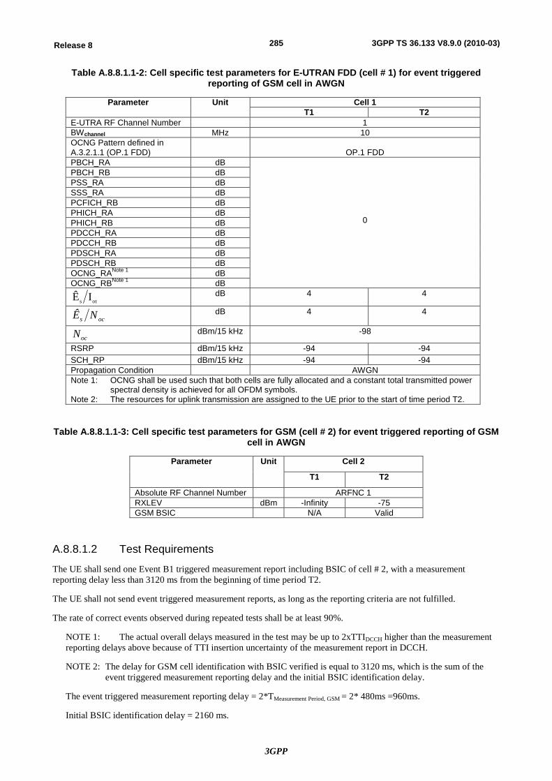
3GPP
285Release 8 3GPP TS 36.133 V8.9.0 (2010-03)
Table A.8.8.1.1-2: Cell specific test parameters for E-UTRAN FDD (cell # 1) for event triggered reporting of GSM cell in AWGN
Parameter Unit Cell 1 T1 T2
E-UTRA RF Channel Number 1 BWchannel MHz 10 OCNG Pattern defined in A.3.2.1.1 (OP.1 FDD)
OP.1 FDD
PBCH_RA dB
0
PBCH_RB dB PSS_RA dB SSS_RA dB PCFICH_RB dB PHICH_RA dB PHICH_RB dB PDCCH_RA dB PDCCH_RB dB PDSCH_RA dB PDSCH_RB dB OCNG_RANote 1 dB OCNG_RBNote 1 dB
ots IÊ dB 4 4
ocs NÊ dB 4 4
ocN dBm/15 kHz -98
RSRP dBm/15 kHz -94 -94 SCH_RP dBm/15 kHz -94 -94 Propagation Condition AWGN Note 1: OCNG shall be used such that both cells are fully allocated and a constant total transmitted power
spectral density is achieved for all OFDM symbols. Note 2: The resources for uplink transmission are assigned to the UE prior to the start of time period T2.
Table A.8.8.1.1-3: Cell specific test parameters for GSM (cell # 2) for event triggered reporting of GSM cell in AWGN
Parameter Unit Cell 2
T1 T2
Absolute RF Channel Number ARFNC 1 RXLEV dBm -Infinity -75 GSM BSIC N/A Valid
A.8.8.1.2 Test Requirements
The UE shall send one Event B1 triggered measurement report including BSIC of cell # 2, with a measurement reporting delay less than 3120 ms from the beginning of time period T2.
The UE shall not send event triggered measurement reports, as long as the reporting criteria are not fulfilled.
The rate of correct events observed during repeated tests shall be at least 90%.
NOTE 1: The actual overall delays measured in the test may be up to 2xTTIDCCH higher than the measurement reporting delays above because of TTI insertion uncertainty of the measurement report in DCCH.
NOTE 2: The delay for GSM cell identification with BSIC verified is equal to 3120 ms, which is the sum of the event triggered measurement reporting delay and the initial BSIC identification delay.
The event triggered measurement reporting delay = 2*TMeasurement Period, GSM = 2* 480ms =960ms.
Initial BSIC identification delay = 2160 ms.
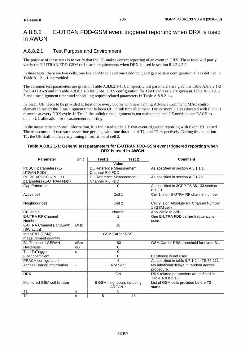
3GPP
286Release 8 3GPP TS 36.133 V8.9.0 (2010-03)
A.8.8.2 E-UTRAN FDD-GSM event triggered reporting when DRX is used in AWGN
A.8.8.2.1 Test Purpose and Environment
The purpose of these tests is to verify that the UE makes correct reporting of an event in DRX. These tests will partly verify the E-UTRAN FDD-GSM cell search requirements when DRX is used in section 8.1.2.4.5.2.
In these tests, there are two cells, one E-UTRAN cell and one GSM cell, and gap pattern configuration # 0 as defined in Table 8.1.2.1-1 is provided.
The common test parameters are given in Table A.8.8.2.1-1. Cell specific test parameters are given in Table A.8.8.2.1-2 for E-UTRAN and in Table A.8.8.2.1-5 for GSM. DRX configuration for Test1 and Test2 are given in Table A.8.8.2.1-3 and time alignment timer and scheduling request related parameters in Table A.8.8.2.1-4.
In Test 1 UE needs to be provided at least once every 500ms with new Timing Advance Command MAC control element to restart the Time aligment timer to keep UE uplink time alignment. Furhtermore UE is allocated with PUSCH resource at every DRX cycle. In Test 2 the uplink time alignment is not maintained and UE needs to use RACH to obtain UL allocation for measurement reporting.
In the measurement control information, it is indicated to the UE that event-triggered reporting with Event B1 is used. The tests consist of two successive time periods, with time duration of T1, and T2 respectively. During time duration T1, the UE shall not have any timing information of cell 2.
Table A.8.8.2.1-1: General test parameters for E-UTRAN FDD-GSM event triggered reporting when DRX is used in AWGN
Parameter Unit Test 1 Test 2 Comment Value
PDSCH parameters (E-UTRAN FDD)
DL Reference Measurement Channel R.0 FDD
As specified in section A.3.1.1.1.
PCFICH/PDCCH/PHICH parameters (E-UTRAN FDD)
DL Reference Measurement Channel R.6 FDD
As specified in section A.3.1.2.1.
Gap Pattern Id 0 As specified in 3GPP TS 36.133 section 8.1.2.1.
Active cell Cell 1 Cell 1 is on E-UTRA RF channel number 1.
Neighbour cell Cell 2 Cell 2 is on Absolute RF Channel Number 1 (GSM cell)
CP length Normal Applicable to cell 1 E-UTRA RF Channel Number
1 One E-UTRA FDD carrier frequency is used.
E-UTRA Channel Bandwidth (BWchannel)
MHz 10
Inter-RAT (GSM) measurement quantity
GSM Carrier RSSI
B1-Threshold-GERAN dBm -80 GSM Carrier RSSI threshold for event B1. Hysteresis dB 0 TimeToTrigger s 0 Filter coefficient 0 L3 filtering is not used PRACH configuration 4 As specified in table 5.7.1-2 in TS 36.211 Access Barring Information - Not Sent No additional delays in random access
procedure. DRX ON DRX related parameters are defined in
Table A.8.8.2.1-3 Monitored GSM cell list size 6 GSM neighbours including
ARFCN 1 List of GSM cells provided before T2 starts.
T1 s 5 T2 s 5 45
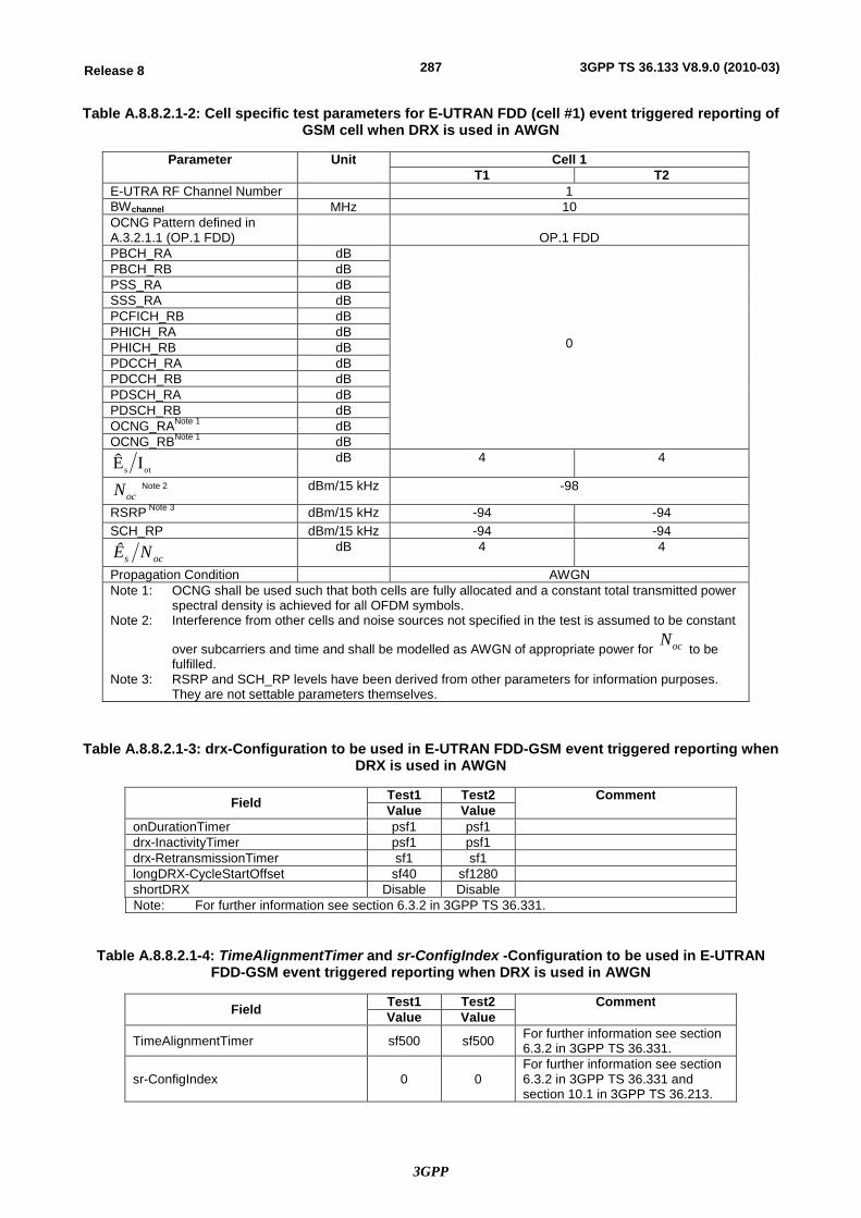
3GPP
287Release 8 3GPP TS 36.133 V8.9.0 (2010-03)
Table A.8.8.2.1-2: Cell specific test parameters for E-UTRAN FDD (cell #1) event triggered reporting of GSM cell when DRX is used in AWGN
Parameter Unit Cell 1 T1 T2
E-UTRA RF Channel Number 1 BWchannel MHz 10 OCNG Pattern defined in A.3.2.1.1 (OP.1 FDD)
OP.1 FDD
PBCH_RA dB
0
PBCH_RB dB PSS_RA dB SSS_RA dB PCFICH_RB dB PHICH_RA dB PHICH_RB dB PDCCH_RA dB PDCCH_RB dB PDSCH_RA dB PDSCH_RB dB OCNG_RANote 1 dB OCNG_RBNote 1 dB
ots IÊ dB 4 4
ocN Note 2 dBm/15 kHz -98
RSRP Note 3 dBm/15 kHz -94 -94 SCH_RP dBm/15 kHz -94 -94
ocs NÊ dB 4 4
Propagation Condition AWGN Note 1: OCNG shall be used such that both cells are fully allocated and a constant total transmitted power
spectral density is achieved for all OFDM symbols. Note 2: Interference from other cells and noise sources not specified in the test is assumed to be constant
over subcarriers and time and shall be modelled as AWGN of appropriate power for ocN to be
fulfilled. Note 3: RSRP and SCH_RP levels have been derived from other parameters for information purposes.
They are not settable parameters themselves.
Table A.8.8.2.1-3: drx-Configuration to be used in E-UTRAN FDD-GSM event triggered reporting when DRX is used in AWGN
Field Test1 Test2 Comment Value Value
onDurationTimer psf1 psf1 drx-InactivityTimer psf1 psf1 drx-RetransmissionTimer sf1 sf1 longDRX-CycleStartOffset sf40 sf1280 shortDRX Disable Disable Note: For further information see section 6.3.2 in 3GPP TS 36.331.
Table A.8.8.2.1-4: TimeAlignmentTimer and sr-ConfigIndex -Configuration to be used in E-UTRAN FDD-GSM event triggered reporting when DRX is used in AWGN
Field Test1 Test2 Comment Value Value
TimeAlignmentTimer sf500 sf500 For further information see section 6.3.2 in 3GPP TS 36.331.
sr-ConfigIndex 0 0 For further information see section 6.3.2 in 3GPP TS 36.331 and section 10.1 in 3GPP TS 36.213.
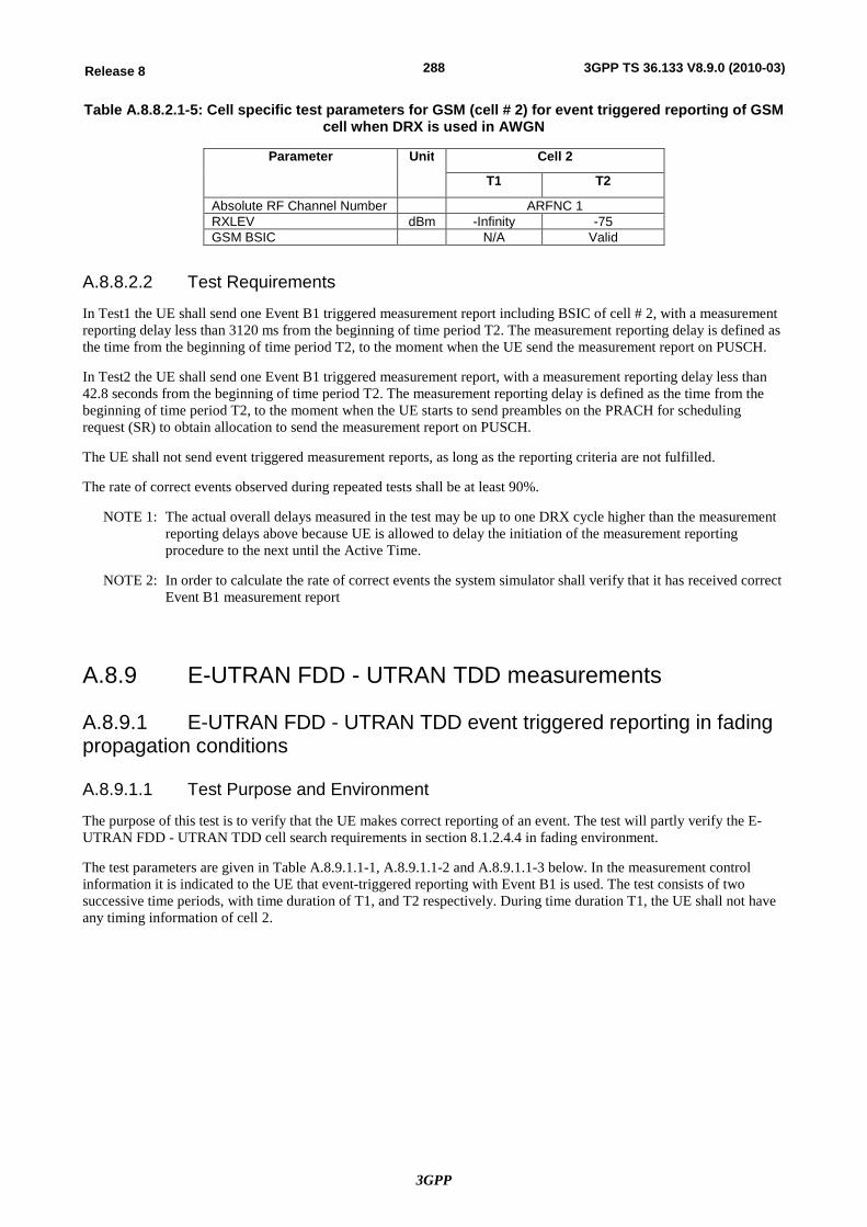
3GPP
288Release 8 3GPP TS 36.133 V8.9.0 (2010-03)
Table A.8.8.2.1-5: Cell specific test parameters for GSM (cell # 2) for event triggered reporting of GSM cell when DRX is used in AWGN
Parameter Unit Cell 2
T1 T2
Absolute RF Channel Number ARFNC 1 RXLEV dBm -Infinity -75 GSM BSIC N/A Valid
A.8.8.2.2 Test Requirements
In Test1 the UE shall send one Event B1 triggered measurement report including BSIC of cell # 2, with a measurement reporting delay less than 3120 ms from the beginning of time period T2. The measurement reporting delay is defined as the time from the beginning of time period T2, to the moment when the UE send the measurement report on PUSCH.
In Test2 the UE shall send one Event B1 triggered measurement report, with a measurement reporting delay less than 42.8 seconds from the beginning of time period T2. The measurement reporting delay is defined as the time from the beginning of time period T2, to the moment when the UE starts to send preambles on the PRACH for scheduling request (SR) to obtain allocation to send the measurement report on PUSCH.
The UE shall not send event triggered measurement reports, as long as the reporting criteria are not fulfilled.
The rate of correct events observed during repeated tests shall be at least 90%.
NOTE 1: The actual overall delays measured in the test may be up to one DRX cycle higher than the measurement reporting delays above because UE is allowed to delay the initiation of the measurement reporting procedure to the next until the Active Time.
NOTE 2: In order to calculate the rate of correct events the system simulator shall verify that it has received correct Event B1 measurement report
A.8.9 E-UTRAN FDD - UTRAN TDD measurements
A.8.9.1 E-UTRAN FDD - UTRAN TDD event triggered reporting in fading propagation conditions
A.8.9.1.1 Test Purpose and Environment
The purpose of this test is to verify that the UE makes correct reporting of an event. The test will partly verify the E-UTRAN FDD - UTRAN TDD cell search requirements in section 8.1.2.4.4 in fading environment.
The test parameters are given in Table A.8.9.1.1-1, A.8.9.1.1-2 and A.8.9.1.1-3 below. In the measurement control information it is indicated to the UE that event-triggered reporting with Event B1 is used. The test consists of two successive time periods, with time duration of T1, and T2 respectively. During time duration T1, the UE shall not have any timing information of cell 2.
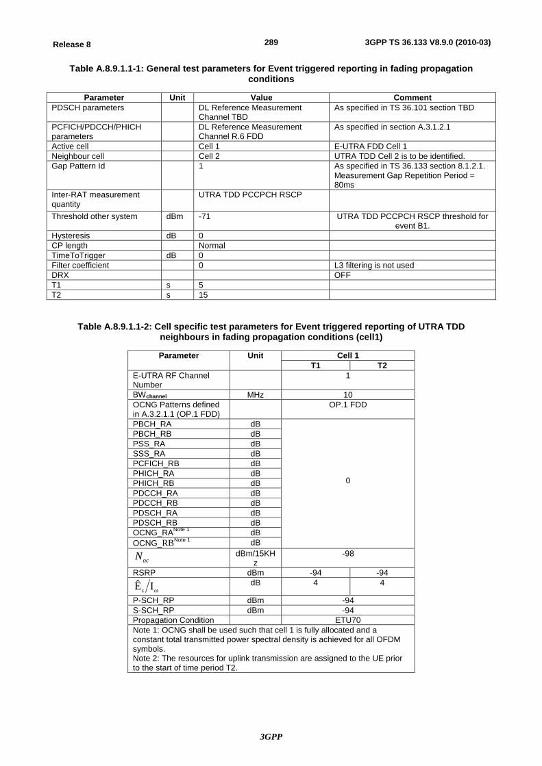
3GPP
289Release 8 3GPP TS 36.133 V8.9.0 (2010-03)
Table A.8.9.1.1-1: General test parameters for Event triggered reporting in fading propagation conditions
Parameter Unit Value Comment PDSCH parameters DL Reference Measurement
Channel TBD As specified in TS 36.101 section TBD
PCFICH/PDCCH/PHICH parameters
DL Reference Measurement Channel R.6 FDD
As specified in section A.3.1.2.1
Active cell Cell 1 E-UTRA FDD Cell 1 Neighbour cell Cell 2 UTRA TDD Cell 2 is to be identified. Gap Pattern Id 1 As specified in TS 36.133 section 8.1.2.1.
Measurement Gap Repetition Period = 80ms
Inter-RAT measurement quantity
UTRA TDD PCCPCH RSCP
Threshold other system dBm -71 UTRA TDD PCCPCH RSCP threshold for event B1.
Hysteresis dB 0 CP length Normal TimeToTrigger dB 0 Filter coefficient 0 L3 filtering is not used DRX OFF T1 s 5 T2 s 15
Table A.8.9.1.1-2: Cell specific test parameters for Event triggered reporting of UTRA TDD neighbours in fading propagation conditions (cell1)
Parameter Unit Cell 1 T1 T2
E-UTRA RF Channel Number
1
BWchannel MHz 10 OCNG Patterns defined in A.3.2.1.1 (OP.1 FDD)
OP.1 FDD
PBCH_RA dB
0
PBCH_RB dB PSS_RA dB SSS_RA dB PCFICH_RB dB PHICH_RA dB PHICH_RB dB PDCCH_RA dB PDCCH_RB dB PDSCH_RA dB PDSCH_RB dB OCNG_RANote 1 dB OCNG_RBNote 1 dB
ocN dBm/15KHz
-98
RSRP dBm -94 -94
ots IÊ dB 4 4
P-SCH_RP dBm -94 S-SCH_RP dBm -94 Propagation Condition ETU70 Note 1: OCNG shall be used such that cell 1 is fully allocated and a constant total transmitted power spectral density is achieved for all OFDM symbols. Note 2: The resources for uplink transmission are assigned to the UE prior to the start of time period T2.
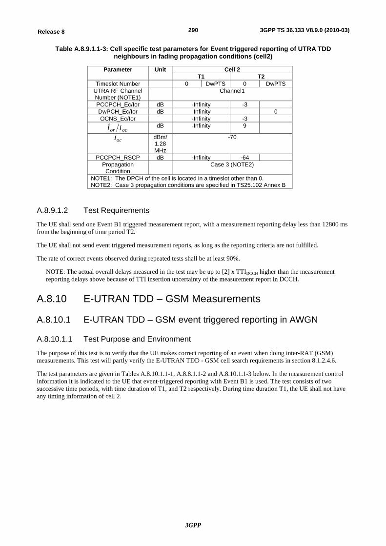
3GPP
290Release 8 3GPP TS 36.133 V8.9.0 (2010-03)
Table A.8.9.1.1-3: Cell specific test parameters for Event triggered reporting of UTRA TDD neighbours in fading propagation conditions (cell2)
Parameter Unit Cell 2 T1 T2
Timeslot Number 0 DwPTS 0 DwPTS UTRA RF Channel Number (NOTE1)
Channel1
PCCPCH_Ec/Ior dB -Infinity -3 DwPCH_Ec/Ior dB -Infinity 0 OCNS_Ec/Ior -Infinity -3
ocor II dB -Infinity 9
ocI dBm/1.28 MHz
-70
PCCPCH_RSCP dB -Infinity -64 Propagation
Condition Case 3 (NOTE2)
NOTE1: The DPCH of the cell is located in a timeslot other than 0. NOTE2: Case 3 propagation conditions are specified in TS25.102 Annex B
A.8.9.1.2 Test Requirements
The UE shall send one Event B1 triggered measurement report, with a measurement reporting delay less than 12800 ms from the beginning of time period T2.
The UE shall not send event triggered measurement reports, as long as the reporting criteria are not fulfilled.
The rate of correct events observed during repeated tests shall be at least 90%.
NOTE: The actual overall delays measured in the test may be up to [2] x TTIDCCH higher than the measurement reporting delays above because of TTI insertion uncertainty of the measurement report in DCCH.
A.8.10 E-UTRAN TDD – GSM Measurements
A.8.10.1 E-UTRAN TDD – GSM event triggered reporting in AWGN
A.8.10.1.1 Test Purpose and Environment
The purpose of this test is to verify that the UE makes correct reporting of an event when doing inter-RAT (GSM) measurements. This test will partly verify the E-UTRAN TDD - GSM cell search requirements in section 8.1.2.4.6.
The test parameters are given in Tables A.8.10.1.1-1, A.8.8.1.1-2 and A.8.10.1.1-3 below. In the measurement control information it is indicated to the UE that event-triggered reporting with Event B1 is used. The test consists of two successive time periods, with time duration of T1, and T2 respectively. During time duration T1, the UE shall not have any timing information of cell 2.
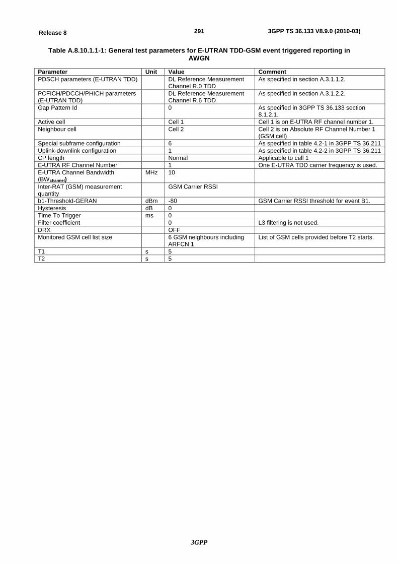
3GPP
291Release 8 3GPP TS 36.133 V8.9.0 (2010-03)
Table A.8.10.1.1-1: General test parameters for E-UTRAN TDD-GSM event triggered reporting in AWGN
Parameter Unit Value Comment PDSCH parameters (E-UTRAN TDD) DL Reference Measurement
Channel R.0 TDD As specified in section A.3.1.1.2.
PCFICH/PDCCH/PHICH parameters (E-UTRAN TDD)
DL Reference Measurement Channel R.6 TDD
As specified in section A.3.1.2.2.
Gap Pattern Id 0 As specified in 3GPP TS 36.133 section 8.1.2.1.
Active cell Cell 1 Cell 1 is on E-UTRA RF channel number 1. Neighbour cell Cell 2 Cell 2 is on Absolute RF Channel Number 1
(GSM cell) Special subframe configuration 6 As specified in table 4.2-1 in 3GPP TS 36.211 Uplink-downlink configuration 1 As specified in table 4.2-2 in 3GPP TS 36.211 CP length Normal Applicable to cell 1 E-UTRA RF Channel Number 1 One E-UTRA TDD carrier frequency is used. E-UTRA Channel Bandwidth (BWchannel)
MHz 10
Inter-RAT (GSM) measurement quantity
GSM Carrier RSSI
b1-Threshold-GERAN dBm -80 GSM Carrier RSSI threshold for event B1. Hysteresis dB 0 Time To Trigger ms 0 Filter coefficient 0 L3 filtering is not used. DRX OFF Monitored GSM cell list size 6 GSM neighbours including
ARFCN 1 List of GSM cells provided before T2 starts.
T1 s 5 T2 s 5
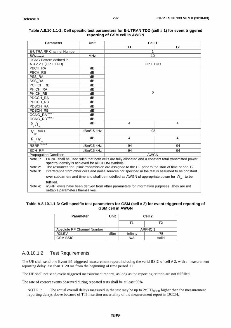
3GPP
292Release 8 3GPP TS 36.133 V8.9.0 (2010-03)
Table A.8.10.1.1-2: Cell specific test parameters for E-UTRAN TDD (cell # 1) for event triggered reporting of GSM cell in AWGN
Parameter Unit Cell 1 T1 T2
E-UTRA RF Channel Number 1 BWchannel MHz 10 OCNG Pattern defined in A.3.2.2.1 (OP.1 TDD)
OP.1 TDD
PBCH_RA dB
0
PBCH_RB dB PSS_RA dB SSS_RA dB PCFICH_RB dB PHICH_RA dB PHICH_RB dB PDCCH_RA dB PDCCH_RB dB PDSCH_RA dB PDSCH_RB dB OCNG_RANote 1 dB OCNG_RBNote 1 dB
ots IÊ dB 4 4
ocN Note 3 dBm/15 kHz -98
ocs NÊ dB 4 4
RSRP Note 4 dBm/15 kHz -94 -94 SCH_RP dBm/15 kHz -94 -94 Propagation Condition AWGN Note 1: OCNG shall be used such that both cells are fully allocated and a constant total transmitted power
spectral density is achieved for all OFDM symbols. Note 2: The resources for uplink transmission are assigned to the UE prior to the start of time period T2. Note 3: Interference from other cells and noise sources not specified in the test is assumed to be constant
over subcarriers and time and shall be modelled as AWGN of appropriate power for ocN to be fulfilled.
Note 4: RSRP levels have been derived from other parameters for information purposes. They are not settable parameters themselves.
Table A.8.10.1.1-3: Cell specific test parameters for GSM (cell # 2) for event triggered reporting of GSM cell in AWGN
Parameter Unit Cell 2
T1 T2
Absolute RF Channel Number ARFNC 1 RXLEV dBm -Infinity -75 GSM BSIC N/A Valid
A.8.10.1.2 Test Requirements
The UE shall send one Event B1 triggered measurement report including the valid BSIC of cell # 2, with a measurement reporting delay less than 3120 ms from the beginning of time period T2.
The UE shall not send event triggered measurement reports, as long as the reporting criteria are not fulfilled.
The rate of correct events observed during repeated tests shall be at least 90%.
NOTE 1: The actual overall delays measured in the test may be up to 2xTTIDCCH higher than the measurement reporting delays above because of TTI insertion uncertainty of the measurement report in DCCH.
3GPP
293Release 8 3GPP TS 36.133 V8.9.0 (2010-03)
NOTE 2: The delay for GSM cell identification with BSIC verified is equal to 3120 ms, which is the sum of the event triggered measurement reporting delay and the initial BSIC identification delay.
The event triggered measurement reporting delay = 2*TMeasurement Period, GSM = 2* 480ms =960ms.
Initial BSIC identification delay = 2160 ms.
A.8.10.2 E-UTRAN TDD-GSM event triggered reporting when DRX is used in AWGN
A.8.10.2.1 Test Purpose and Environment
The purpose of these tests is to verify that the UE makes correct reporting of an event in DRX. These tests will partly verify the E-UTRAN TDD-GSM cell search requirements when DRX is used in section 8.1.2.4.6.
In these tests, there are two cells, one E-UTRAN cell and one GSM cell, and gap pattern configuration # 0 as defined in Table 8.1.2.1-1 is provided.
The common test parameters are given in Table A.8.10.2.1-1. Cell specific test parameters are given in Table A.8.10.2.1-2 for E-UTRAN and in Table A.8.10.2.1-5 for GSM. DRX configuration for Test1 and Test2 are given in Table A.8.10.2.1-3 and time alignment timer and scheduling request related parameters in Table A.8.10.2.1-4.
In Test 1 UE needs to be provided at least once every 500ms with new Timing Advance Command MAC control element to restart the Time aligment timer to keep UE uplink time alignment. Furhtermore UE is allocated with PUSCH resource at every DRX cycle. In Test 2 the uplink time alignment is not maintained and UE needs to use RACH to obtain UL allocation for measurement reporting.
In the measurement control information, it is indicated to the UE that event-triggered reporting with Event B1 is used. The tests consist of two successive time periods, with time duration of T1, and T2 respectively. During time duration T1, the UE shall not have any timing information of cell 2.
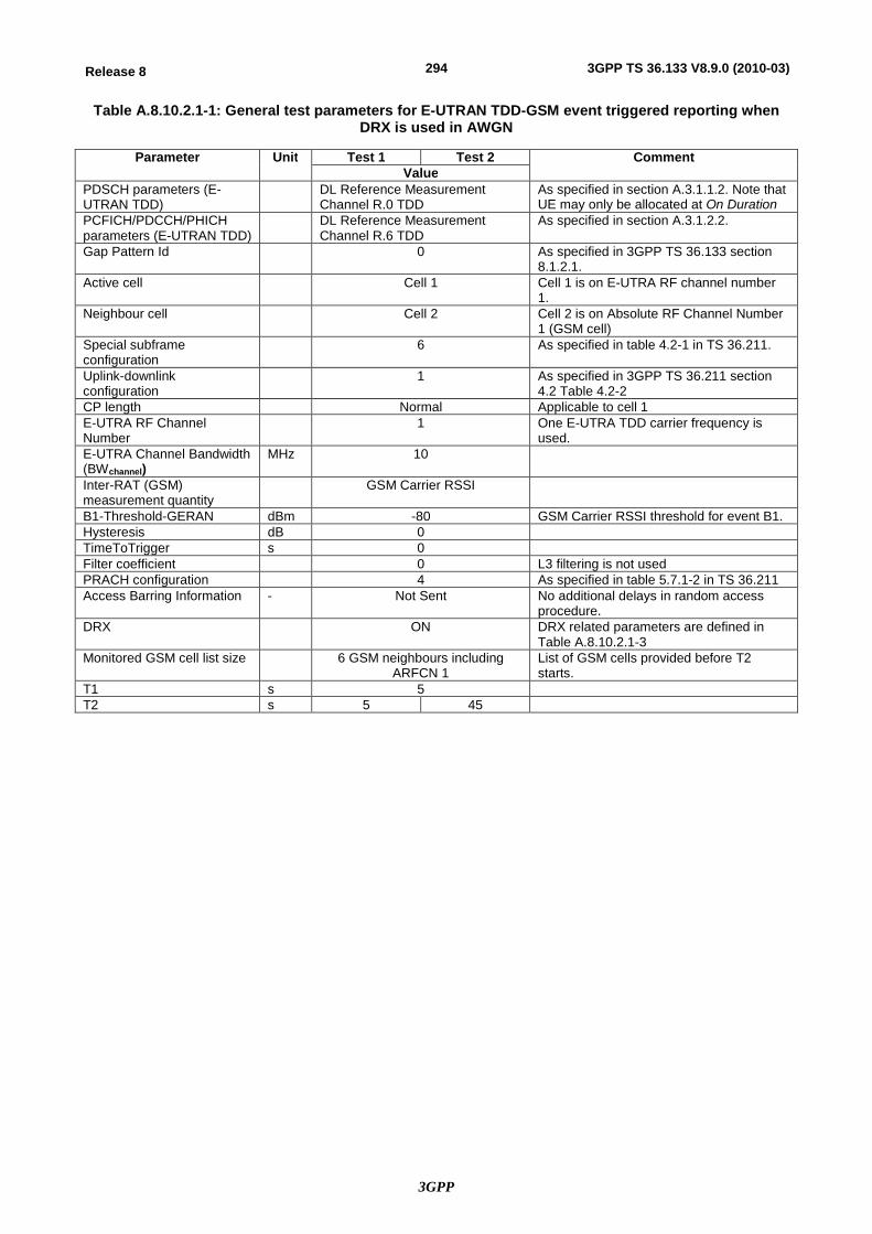
3GPP
294Release 8 3GPP TS 36.133 V8.9.0 (2010-03)
Table A.8.10.2.1-1: General test parameters for E-UTRAN TDD-GSM event triggered reporting when DRX is used in AWGN
Parameter Unit Test 1 Test 2 Comment Value
PDSCH parameters (E-UTRAN TDD)
DL Reference Measurement Channel R.0 TDD
As specified in section A.3.1.1.2. Note that UE may only be allocated at On Duration
PCFICH/PDCCH/PHICH parameters (E-UTRAN TDD)
DL Reference Measurement Channel R.6 TDD
As specified in section A.3.1.2.2.
Gap Pattern Id 0 As specified in 3GPP TS 36.133 section 8.1.2.1.
Active cell Cell 1 Cell 1 is on E-UTRA RF channel number 1.
Neighbour cell Cell 2 Cell 2 is on Absolute RF Channel Number 1 (GSM cell)
Special subframe configuration
6 As specified in table 4.2-1 in TS 36.211.
Uplink-downlink configuration
1 As specified in 3GPP TS 36.211 section 4.2 Table 4.2-2
CP length Normal Applicable to cell 1 E-UTRA RF Channel Number
1 One E-UTRA TDD carrier frequency is used.
E-UTRA Channel Bandwidth (BWchannel)
MHz 10
Inter-RAT (GSM) measurement quantity
GSM Carrier RSSI
B1-Threshold-GERAN dBm -80 GSM Carrier RSSI threshold for event B1. Hysteresis dB 0 TimeToTrigger s 0 Filter coefficient 0 L3 filtering is not used PRACH configuration 4 As specified in table 5.7.1-2 in TS 36.211 Access Barring Information - Not Sent No additional delays in random access
procedure. DRX ON DRX related parameters are defined in
Table A.8.10.2.1-3 Monitored GSM cell list size 6 GSM neighbours including
ARFCN 1 List of GSM cells provided before T2 starts.
T1 s 5 T2 s 5 45

3GPP
295Release 8 3GPP TS 36.133 V8.9.0 (2010-03)
Table A.8.10.2.1-2: Cell specific test parameters for E-UTRAN TDD (cell #1) event triggered reporting of GSM cell when DRX is used in AWGN
Parameter Unit Cell 1 T1 T2
E-UTRA RF Channel Number 1 BWchannel MHz 10 OCNG Patterns defined in A.3.2.2.1 (OP.1 TDD)
OP.1 TDD
PBCH_RA dB
0
PBCH_RB dB PSS_RA dB SSS_RA dB PCFICH_RB dB PHICH_RA dB PHICH_RB dB PDCCH_RA dB PDCCH_RB dB PDSCH_RA dB PDSCH_RB dB OCNG_RANote 1 dB OCNG_RBNote 1 dB
ots IÊ dB 4 4
ocN Note 2 dBm/15 kHz -98
RSRP Note 3 dBm/15 kHz -94 -94 SCH_RP dBm/15 kHz -94 -94
ocs NÊ dB 4 4
Propagation Condition AWGN Note 1: OCNG shall be used such that both cells are fully allocated and a constant total transmitted power
spectral density is achieved for all OFDM symbols. Note 2: Interference from other cells and noise sources not specified in the test is assumed to be constant
over subcarriers and time and shall be modelled as AWGN of appropriate power for ocN to be
fulfilled. Note 3: RSRP and SCH_RP levels have been derived from other parameters for information purposes.
They are not settable parameters themselves.
Table A.8.10.2.1-3: drx-Configuration to be used in E-UTRAN TDD-GSM event triggered reporting when DRX is used in AWGN
Field Test1 Test2 Comment Value Value
onDurationTimer psf1 psf1 drx-InactivityTimer psf1 psf1 drx-RetransmissionTimer sf1 sf1 longDRX-CycleStartOffset sf40 sf1280 shortDRX Disable Disable
Note: For further information see section 6.3.2 in 3GPP TS 36.331.
Table A.8.10.2.1-4: TimeAlignmentTimer and sr-ConfigIndex -Configuration to be used in E-UTRAN TDD-GSM event triggered reporting when DRX is used in AWGN
Field Test1 Test2 Comment Value Value
TimeAlignmentTimer sf500 sf500 For further information see section 6.3.2 in 3GPP TS 36.331.
sr-ConfigIndex 0 0 For further information see section 6.3.2 in 3GPP TS 36.331 and section 10.1 in 3GPP TS 36.213.
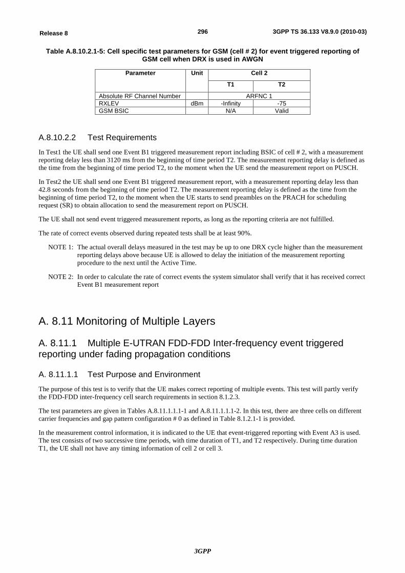
3GPP
296Release 8 3GPP TS 36.133 V8.9.0 (2010-03)
Table A.8.10.2.1-5: Cell specific test parameters for GSM (cell # 2) for event triggered reporting of GSM cell when DRX is used in AWGN
Parameter Unit Cell 2
T1 T2
Absolute RF Channel Number ARFNC 1 RXLEV dBm -Infinity -75 GSM BSIC N/A Valid
A.8.10.2.2 Test Requirements
In Test1 the UE shall send one Event B1 triggered measurement report including BSIC of cell # 2, with a measurement reporting delay less than 3120 ms from the beginning of time period T2. The measurement reporting delay is defined as the time from the beginning of time period T2, to the moment when the UE send the measurement report on PUSCH.
In Test2 the UE shall send one Event B1 triggered measurement report, with a measurement reporting delay less than 42.8 seconds from the beginning of time period T2. The measurement reporting delay is defined as the time from the beginning of time period T2, to the moment when the UE starts to send preambles on the PRACH for scheduling request (SR) to obtain allocation to send the measurement report on PUSCH.
The UE shall not send event triggered measurement reports, as long as the reporting criteria are not fulfilled.
The rate of correct events observed during repeated tests shall be at least 90%.
NOTE 1: The actual overall delays measured in the test may be up to one DRX cycle higher than the measurement reporting delays above because UE is allowed to delay the initiation of the measurement reporting procedure to the next until the Active Time.
NOTE 2: In order to calculate the rate of correct events the system simulator shall verify that it has received correct Event B1 measurement report
A. 8.11 Monitoring of Multiple Layers
A. 8.11.1 Multiple E-UTRAN FDD-FDD Inter-frequency event triggered reporting under fading propagation conditions
A. 8.11.1.1 Test Purpose and Environment
The purpose of this test is to verify that the UE makes correct reporting of multiple events. This test will partly verify the FDD-FDD inter-frequency cell search requirements in section 8.1.2.3.
The test parameters are given in Tables A.8.11.1.1.1-1 and A.8.11.1.1.1-2. In this test, there are three cells on different carrier frequencies and gap pattern configuration # 0 as defined in Table 8.1.2.1-1 is provided.
In the measurement control information, it is indicated to the UE that event-triggered reporting with Event A3 is used. The test consists of two successive time periods, with time duration of T1, and T2 respectively. During time duration T1, the UE shall not have any timing information of cell 2 or cell 3.
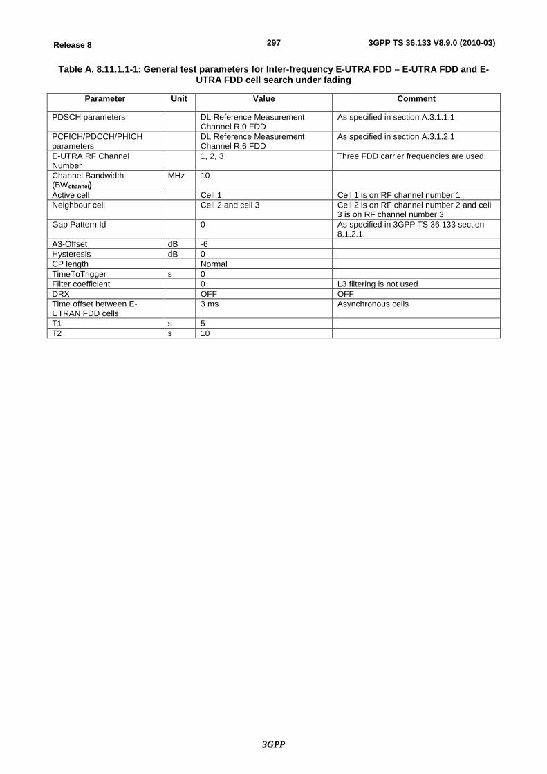
3GPP
297Release 8 3GPP TS 36.133 V8.9.0 (2010-03)
Table A. 8.11.1.1-1: General test parameters for Inter-frequency E-UTRA FDD – E-UTRA FDD and E-UTRA FDD cell search under fading
Parameter Unit Value Comment
PDSCH parameters DL Reference Measurement Channel R.0 FDD
As specified in section A.3.1.1.1
PCFICH/PDCCH/PHICH parameters
DL Reference Measurement Channel R.6 FDD
As specified in section A.3.1.2.1
E-UTRA RF Channel Number
1, 2, 3 Three FDD carrier frequencies are used.
Channel Bandwidth (BWchannel)
MHz 10
Active cell Cell 1 Cell 1 is on RF channel number 1 Neighbour cell Cell 2 and cell 3 Cell 2 is on RF channel number 2 and cell
3 is on RF channel number 3 Gap Pattern Id 0 As specified in 3GPP TS 36.133 section
8.1.2.1. A3-Offset dB -6 Hysteresis dB 0 CP length Normal TimeToTrigger s 0 Filter coefficient 0 L3 filtering is not used DRX OFF OFF Time offset between E-UTRAN FDD cells
3 ms Asynchronous cells
T1 s 5 T2 s 10
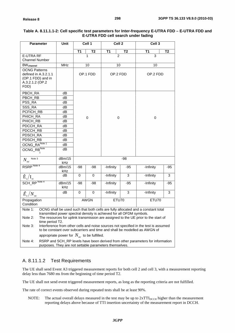
3GPP
298Release 8 3GPP TS 36.133 V8.9.0 (2010-03)
Table A. 8.11.1.1-2: Cell specific test parameters for Inter-frequency E-UTRA FDD – E-UTRA FDD and E-UTRA FDD cell search under fading
Parameter Unit Cell 1 Cell 2 Cell 3
T1 T2 T1 T2 T1 T2 E-UTRA RF Channel Number
1 2 3
BWchannel MHz 10 10 10 OCNG Patterns defined in A.3.2.1.1 (OP.1 FDD) and in A.3.2.1.2 (OP.2 FDD)
OP.1 FDD
OP.2 FDD
OP.2 FDD
PBCH_RA dB
0
0
0
PBCH_RB dB PSS_RA dB SSS_RA dB PCFICH_RB dB PHICH_RA dB PHICH_RB dB PDCCH_RA dB PDCCH_RB dB PDSCH_RA dB PDSCH_RB dB OCNG_RANote 1 dB OCNG_RBNote
1 dB
ocN Note 3 dBm/15 kHz
-98
RSRP Note 4 dBm/15 kHz
-98 -98 -Infinity -95 -Infinity -95
ots IÊ dB 0 0 -Infinity 3 -Infinity 3
SCH_RP Note 4 dBm/15 kHz
-98 -98 -Infinity -95 -Infinity -95
ocs NÊ dB 0 0 -Infinity 3 -Infinity 3
Propagation Condition
AWGN ETU70 ETU70
Note 1: OCNG shall be used such that both cells are fully allocated and a constant total transmitted power spectral density is achieved for all OFDM symbols.
Note 2: The resources for uplink transmission are assigned to the UE prior to the start of time period T2.
Note 3: Interference from other cells and noise sources not specified in the test is assumed to be constant over subcarriers and time and shall be modelled as AWGN of appropriate power for ocN to be fulfilled.
Note 4: RSRP and SCH_RP levels have been derived from other parameters for information purposes. They are not settable parameters themselves.
A. 8.11.1.2 Test Requirements
The UE shall send Event A3 triggered measurement reports for both cell 2 and cell 3, with a measurement reporting delay less than 7680 ms from the beginning of time period T2.
The UE shall not send event triggered measurement reports, as long as the reporting criteria are not fulfilled.
The rate of correct events observed during repeated tests shall be at least 90%.
NOTE: The actual overall delays measured in the test may be up to 2xTTIDCCH higher than the measurement reporting delays above because of TTI insertion uncertainty of the measurement report in DCCH.
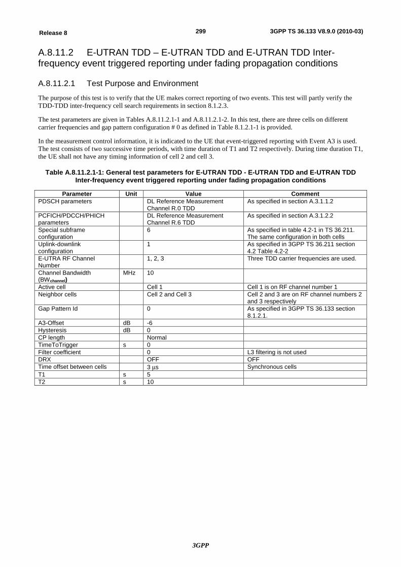
3GPP
299Release 8 3GPP TS 36.133 V8.9.0 (2010-03)
A.8.11.2 E-UTRAN TDD – E-UTRAN TDD and E-UTRAN TDD Inter-frequency event triggered reporting under fading propagation conditions
A.8.11.2.1 Test Purpose and Environment
The purpose of this test is to verify that the UE makes correct reporting of two events. This test will partly verify the TDD-TDD inter-frequency cell search requirements in section 8.1.2.3.
The test parameters are given in Tables A.8.11.2.1-1 and A.8.11.2.1-2. In this test, there are three cells on different carrier frequencies and gap pattern configuration # 0 as defined in Table 8.1.2.1-1 is provided.
In the measurement control information, it is indicated to the UE that event-triggered reporting with Event A3 is used. The test consists of two successive time periods, with time duration of T1 and T2 respectively. During time duration T1, the UE shall not have any timing information of cell 2 and cell 3.
Table A.8.11.2.1-1: General test parameters for E-UTRAN TDD - E-UTRAN TDD and E-UTRAN TDD Inter-frequency event triggered reporting under fading propagation conditions
Parameter Unit Value Comment PDSCH parameters DL Reference Measurement
Channel R.0 TDD As specified in section A.3.1.1.2
PCFICH/PDCCH/PHICH parameters
DL Reference Measurement Channel R.6 TDD
As specified in section A.3.1.2.2
Special subframe configuration
6 As specified in table 4.2-1 in TS 36.211. The same configuration in both cells
Uplink-downlink configuration
1 As specified in 3GPP TS 36.211 section 4.2 Table 4.2-2
E-UTRA RF Channel Number
1, 2, 3 Three TDD carrier frequencies are used.
Channel Bandwidth (BWchannel)
MHz 10
Active cell Cell 1 Cell 1 is on RF channel number 1 Neighbor cells Cell 2 and Cell 3 Cell 2 and 3 are on RF channel numbers 2
and 3 respectively Gap Pattern Id 0 As specified in 3GPP TS 36.133 section
8.1.2.1. A3-Offset dB -6 Hysteresis dB 0 CP length Normal TimeToTrigger s 0 Filter coefficient 0 L3 filtering is not used DRX OFF OFF Time offset between cells 3 ms Synchronous cells T1 s 5 T2 s 10
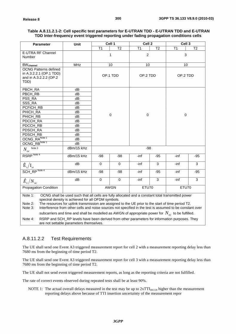
3GPP
300Release 8 3GPP TS 36.133 V8.9.0 (2010-03)
Table A.8.11.2.1-2: Cell specific test parameters for E-UTRAN TDD - E-UTRAN TDD and E-UTRAN TDD Inter-frequency event triggered reporting under fading propagation conditions cells
Parameter Unit Cell 1 Cell 2 Cell 3 T1 T2 T1 T2 T1 T2
E-UTRA RF Channel Number 1 2 3
BWchannel MHz 10 10 10 OCNG Patterns defined in A.3.2.2.1 (OP.1 TDD) and in A.3.2.2.2 (OP.2 TDD)
OP.1 TDD OP.2 TDD OP.2 TDD
PBCH_RA dB
0 0 0
PBCH_RB dB PSS_RA dB SSS_RA dB PCFICH_RB dB PHICH_RA dB PHICH_RB dB PDCCH_RA dB PDCCH_RB dB PDSCH_RA dB PDSCH_RB dB OCNG_RANote 1 dB OCNG_RBNote 1 dB
ocN Note 3 dBm/15 kHz -98
RSRP Note 4 dBm/15 kHz -98 -98 -inf -95 -inf -95
ots IÊ dB 0 0 -inf 3 -inf 3
SCH_RP Note 4 dBm/15 kHz -98 -98 -inf -95 -inf -95
ocs NÊ dB 0 0 -inf 3 -inf 3
Propagation Condition AWGN ETU70 ETU70
Note 1: OCNG shall be used such that all cells are fully allocated and a constant total transmitted power spectral density is achieved for all OFDM symbols.
Note 2: The resources for uplink transmission are assigned to the UE prior to the start of time period T2. Note 3: Interference from other cells and noise sources not specified in the test is assumed to be constant over
subcarriers and time and shall be modelled as AWGN of appropriate power for ocN to be fulfilled. Note 4: RSRP and SCH_RP levels have been derived from other parameters for information purposes. They
are not settable parameters themselves.
A.8.11.2.2 Test Requirements
The UE shall send one Event A3 triggered measurement report for cell 2 with a measurement reporting delay less than 7680 ms from the beginning of time period T2.
The UE shall send one Event A3 triggered measurement report for cell 3 with a measurement reporting delay less than 7680 ms from the beginning of time period T2.
The UE shall not send event triggered measurement reports, as long as the reporting criteria are not fulfilled.
The rate of correct events observed during repeated tests shall be at least 90%.
NOTE 1: The actual overall delays measured in the test may be up to 2xTTIDCCH higher than the measurement reporting delays above because of TTI insertion uncertainty of the measurement repor
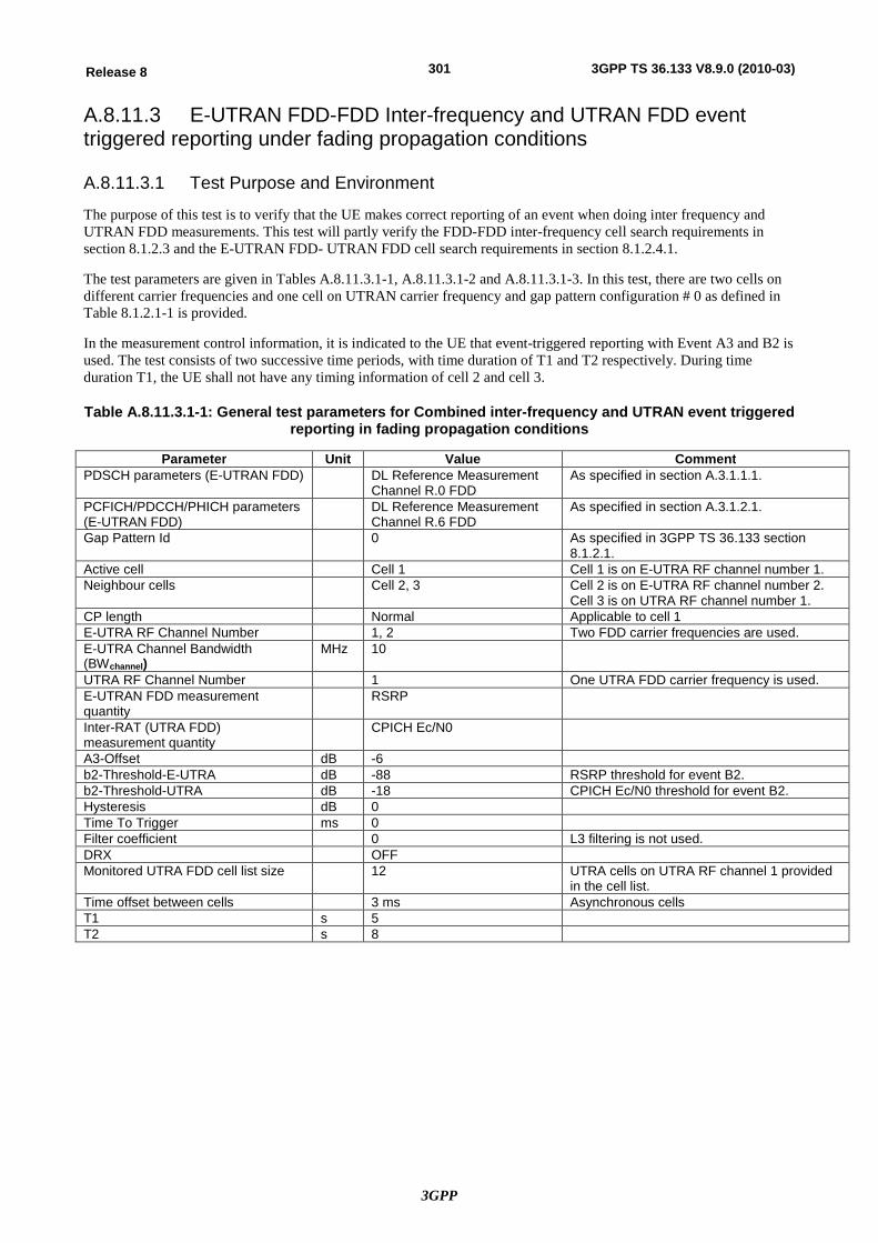
3GPP
301Release 8 3GPP TS 36.133 V8.9.0 (2010-03)
A.8.11.3 E-UTRAN FDD-FDD Inter-frequency and UTRAN FDD event triggered reporting under fading propagation conditions
A.8.11.3.1 Test Purpose and Environment
The purpose of this test is to verify that the UE makes correct reporting of an event when doing inter frequency and UTRAN FDD measurements. This test will partly verify the FDD-FDD inter-frequency cell search requirements in section 8.1.2.3 and the E-UTRAN FDD- UTRAN FDD cell search requirements in section 8.1.2.4.1.
The test parameters are given in Tables A.8.11.3.1-1, A.8.11.3.1-2 and A.8.11.3.1-3. In this test, there are two cells on different carrier frequencies and one cell on UTRAN carrier frequency and gap pattern configuration # 0 as defined in Table 8.1.2.1-1 is provided.
In the measurement control information, it is indicated to the UE that event-triggered reporting with Event A3 and B2 is used. The test consists of two successive time periods, with time duration of T1 and T2 respectively. During time duration T1, the UE shall not have any timing information of cell 2 and cell 3.
Table A.8.11.3.1-1: General test parameters for Combined inter-frequency and UTRAN event triggered reporting in fading propagation conditions
Parameter Unit Value Comment PDSCH parameters (E-UTRAN FDD) DL Reference Measurement
Channel R.0 FDD As specified in section A.3.1.1.1.
PCFICH/PDCCH/PHICH parameters (E-UTRAN FDD)
DL Reference Measurement Channel R.6 FDD
As specified in section A.3.1.2.1.
Gap Pattern Id 0 As specified in 3GPP TS 36.133 section 8.1.2.1.
Active cell Cell 1 Cell 1 is on E-UTRA RF channel number 1. Neighbour cells Cell 2, 3 Cell 2 is on E-UTRA RF channel number 2.
Cell 3 is on UTRA RF channel number 1. CP length Normal Applicable to cell 1 E-UTRA RF Channel Number 1, 2 Two FDD carrier frequencies are used. E-UTRA Channel Bandwidth (BWchannel)
MHz 10
UTRA RF Channel Number 1 One UTRA FDD carrier frequency is used. E-UTRAN FDD measurement quantity
RSRP
Inter-RAT (UTRA FDD) measurement quantity
CPICH Ec/N0
A3-Offset dB -6 b2-Threshold-E-UTRA dB -88 RSRP threshold for event B2. b2-Threshold-UTRA dB -18 CPICH Ec/N0 threshold for event B2. Hysteresis dB 0 Time To Trigger ms 0 Filter coefficient 0 L3 filtering is not used. DRX OFF Monitored UTRA FDD cell list size 12 UTRA cells on UTRA RF channel 1 provided
in the cell list. Time offset between cells 3 ms Asynchronous cells T1 s 5 T2 s 8
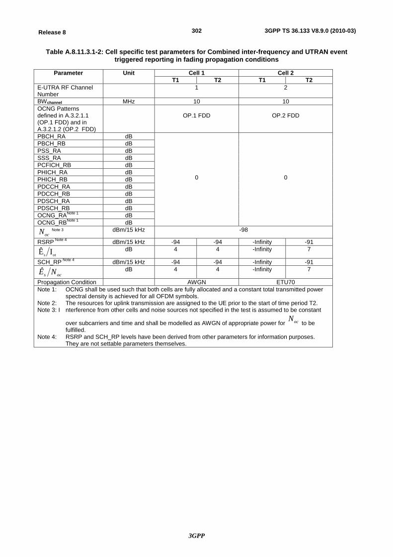
3GPP
302Release 8 3GPP TS 36.133 V8.9.0 (2010-03)
Table A.8.11.3.1-2: Cell specific test parameters for Combined inter-frequency and UTRAN event triggered reporting in fading propagation conditions
Parameter Unit Cell 1 Cell 2 T1 T2 T1 T2
E-UTRA RF Channel Number
1 2
BWchannel MHz 10 10 OCNG Patterns defined in A.3.2.1.1 (OP.1 FDD) and in A.3.2.1.2 (OP.2 FDD)
OP.1 FDD
OP.2 FDD
PBCH_RA dB
0
0
PBCH_RB dB PSS_RA dB SSS_RA dB PCFICH_RB dB PHICH_RA dB PHICH_RB dB PDCCH_RA dB PDCCH_RB dB PDSCH_RA dB PDSCH_RB dB OCNG_RANote 1 dB OCNG_RBNote 1 dB
ocN Note 3 dBm/15 kHz -98
RSRP Note 4 dBm/15 kHz -94 -94 -Infinity -91
ots IÊ dB 4 4 -Infinity 7
SCH_RP Note 4 dBm/15 kHz -94 -94 -Infinity -91
ocs NÊ dB 4 4 -Infinity 7
Propagation Condition AWGN ETU70 Note 1: OCNG shall be used such that both cells are fully allocated and a constant total transmitted power
spectral density is achieved for all OFDM symbols. Note 2: The resources for uplink transmission are assigned to the UE prior to the start of time period T2. Note 3: I nterference from other cells and noise sources not specified in the test is assumed to be constant
over subcarriers and time and shall be modelled as AWGN of appropriate power for ocN to be
fulfilled. Note 4: RSRP and SCH_RP levels have been derived from other parameters for information purposes.
They are not settable parameters themselves.
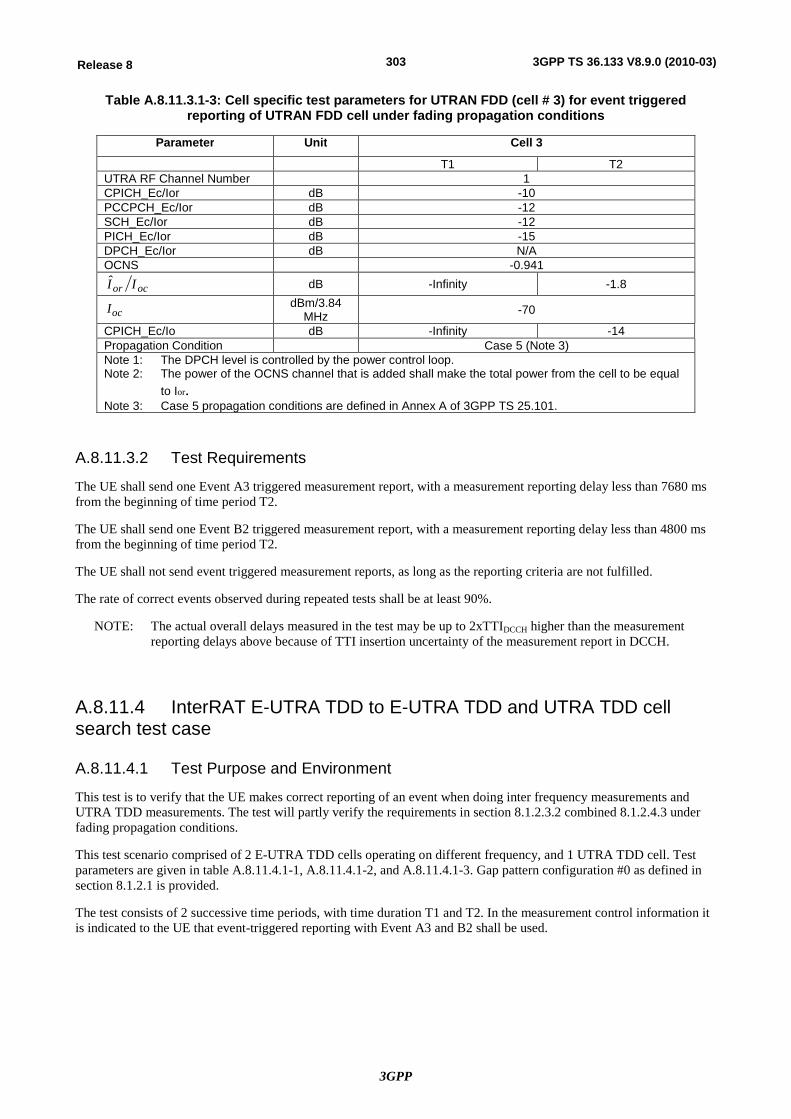
3GPP
303Release 8 3GPP TS 36.133 V8.9.0 (2010-03)
Table A.8.11.3.1-3: Cell specific test parameters for UTRAN FDD (cell # 3) for event triggered reporting of UTRAN FDD cell under fading propagation conditions
Parameter Unit Cell 3
T1 T2 UTRA RF Channel Number 1 CPICH_Ec/Ior dB -10 PCCPCH_Ec/Ior dB -12 SCH_Ec/Ior dB -12 PICH_Ec/Ior dB -15 DPCH_Ec/Ior dB N/A OCNS -0.941
ocor II dB -Infinity -1.8
ocI dBm/3.84 MHz -70
CPICH_Ec/Io dB -Infinity -14 Propagation Condition Case 5 (Note 3) Note 1: The DPCH level is controlled by the power control loop. Note 2: The power of the OCNS channel that is added shall make the total power from the cell to be equal
to Ior.
Note 3: Case 5 propagation conditions are defined in Annex A of 3GPP TS 25.101.
A.8.11.3.2 Test Requirements
The UE shall send one Event A3 triggered measurement report, with a measurement reporting delay less than 7680 ms from the beginning of time period T2.
The UE shall send one Event B2 triggered measurement report, with a measurement reporting delay less than 4800 ms from the beginning of time period T2.
The UE shall not send event triggered measurement reports, as long as the reporting criteria are not fulfilled.
The rate of correct events observed during repeated tests shall be at least 90%.
NOTE: The actual overall delays measured in the test may be up to 2xTTIDCCH higher than the measurement reporting delays above because of TTI insertion uncertainty of the measurement report in DCCH.
A.8.11.4 InterRAT E-UTRA TDD to E-UTRA TDD and UTRA TDD cell search test case
A.8.11.4.1 Test Purpose and Environment
This test is to verify that the UE makes correct reporting of an event when doing inter frequency measurements and UTRA TDD measurements. The test will partly verify the requirements in section 8.1.2.3.2 combined 8.1.2.4.3 under fading propagation conditions.
This test scenario comprised of 2 E-UTRA TDD cells operating on different frequency, and 1 UTRA TDD cell. Test parameters are given in table A.8.11.4.1-1, A.8.11.4.1-2, and A.8.11.4.1-3. Gap pattern configuration #0 as defined in section 8.1.2.1 is provided.
The test consists of 2 successive time periods, with time duration T1 and T2. In the measurement control information it is indicated to the UE that event-triggered reporting with Event A3 and B2 shall be used.
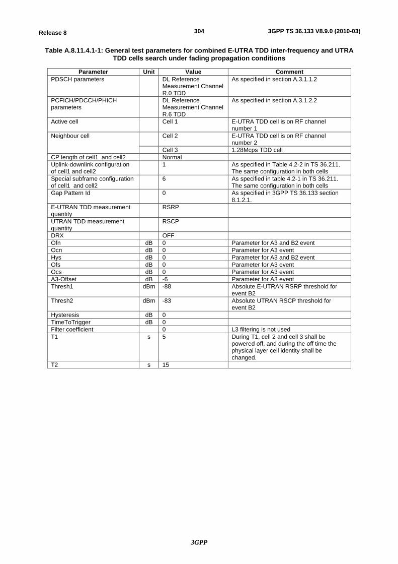
3GPP
304Release 8 3GPP TS 36.133 V8.9.0 (2010-03)
Table A.8.11.4.1-1: General test parameters for combined E-UTRA TDD inter-frequency and UTRA TDD cells search under fading propagation conditions
Parameter Unit Value Comment PDSCH parameters DL Reference
Measurement Channel R.0 TDD
As specified in section A.3.1.1.2
PCFICH/PDCCH/PHICH parameters
DL Reference Measurement Channel R.6 TDD
As specified in section A.3.1.2.2
Active cell Cell 1 E-UTRA TDD cell is on RF channel number 1
Neighbour cell Cell 2 E-UTRA TDD cell is on RF channel number 2
Cell 3 1.28Mcps TDD cell CP length of cell1 and cell2 Normal Uplink-downlink configuration of cell1 and cell2
1 As specified in Table 4.2-2 in TS 36.211. The same configuration in both cells
Special subframe configuration of cell1 and cell2
6 As specified in table 4.2-1 in TS 36.211. The same configuration in both cells
Gap Pattern Id 0 As specified in 3GPP TS 36.133 section 8.1.2.1.
E-UTRAN TDD measurement quantity
RSRP
UTRAN TDD measurement quantity
RSCP
DRX OFF Ofn dB 0 Parameter for A3 and B2 event Ocn dB 0 Parameter for A3 event Hys dB 0 Parameter for A3 and B2 event Ofs dB 0 Parameter for A3 event Ocs dB 0 Parameter for A3 event A3-Offset dB -6 Parameter for A3 event Thresh1 dBm -88 Absolute E-UTRAN RSRP threshold for
event B2 Thresh2 dBm -83 Absolute UTRAN RSCP threshold for
event B2 Hysteresis dB 0 TimeToTrigger dB 0 Filter coefficient 0 L3 filtering is not used T1 s 5 During T1, cell 2 and cell 3 shall be
powered off, and during the off time the physical layer cell identity shall be changed.
T2 s 15
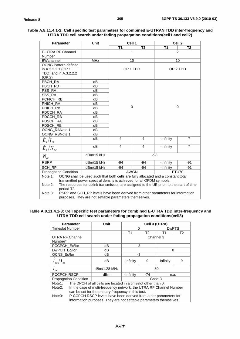
3GPP
305Release 8 3GPP TS 36.133 V8.9.0 (2010-03)
Table A.8.11.4.1-2: Cell specific test parameters for combined E-UTRAN TDD inter-frequency and UTRA TDD cell search under fading propagation conditions(cell1 and cell2)
Parameter Unit Cell 1 Cell 2 T1 T2 T1 T2
E-UTRA RF Channel Number
1 2
BWchannel MHz 10 10 OCNG Pattern defined in A.3.2.2.1 (OP.1 TDD) and in A.3.2.2.2 (OP.2)
OP.1 TDD
OP.2 TDD
PBCH_RA dB
0
0
PBCH_RB dB PSS_RA dB SSS_RA dB PCFICH_RB dB PHICH_RA dB PHICH_RB dB PDCCH_RA dB PDCCH_RB dB PDSCH_RA dB PDSCH_RB dB OCNG_RANote 1 dB OCNG_RBNote 1 dB
ots IÊ
dB 4 4 -Infinity 7
ocs NÊ dB 4 4
-Infinity 7
ocN
dBm/15 kHz -98
RSRP dBm/15 kHz -94 -94 -Infinity -91 SCH_RP dBm/15 kHz -94 -94 -infinity -91 Propagation Condition AWGN ETU70 Note 1: OCNG shall be used such that both cells are fully allocated and a constant total
transmitted power spectral density is achieved for all OFDM symbols. Note 2: The resources for uplink transmission are assigned to the UE priori to the start of time
period T2. Note 3: RSRP and SCH_RP levels have been derived from other parameters for information
purposes. They are not settable parameters themselves.
Table A.8.11.4.1-3: Cell specific test parameters for combined E-UTRA TDD inter-frequency and UTRA TDD cell search under fading propagation conditions(cell3)
Parameter Unit Cell 3 (UTRA) Timeslot Number 0 DwPTS T1 T2 T1 T2 UTRA RF Channel Number* Channel 3
PCCPCH_Ec/Ior dB -3 DwPCH_Ec/Ior dB 0 OCNS_Ec/Ior dB -3
ocor II
dB -Infinity 9 -Infinity 9
ocI dBm/1.28 MHz -80
PCCPCH RSCP dBm -Infinity -74 n.a. Propagation Condition Case 3 Note1: The DPCH of all cells are located in a timeslot other than 0. Note2: In the case of multi-frequency network, the UTRA RF Channel Number
can be set for the primary frequency in this test. Note3: P-CCPCH RSCP levels have been derived from other parameters for
information purposes. They are not settable parameters themselves.
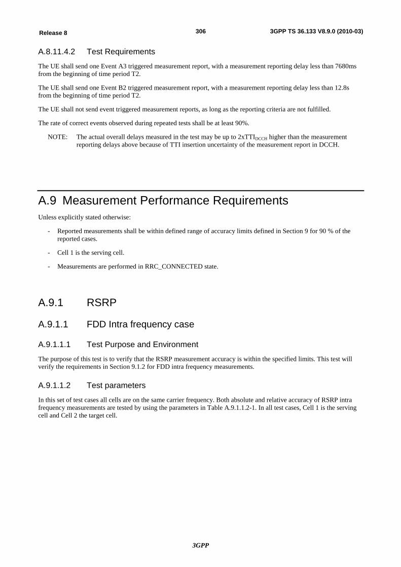
3GPP
306Release 8 3GPP TS 36.133 V8.9.0 (2010-03)
A.8.11.4.2 Test Requirements
The UE shall send one Event A3 triggered measurement report, with a measurement reporting delay less than 7680ms from the beginning of time period T2.
The UE shall send one Event B2 triggered measurement report, with a measurement reporting delay less than 12.8s from the beginning of time period T2.
The UE shall not send event triggered measurement reports, as long as the reporting criteria are not fulfilled.
The rate of correct events observed during repeated tests shall be at least 90%.
NOTE: The actual overall delays measured in the test may be up to 2xTTIDCCH higher than the measurement reporting delays above because of TTI insertion uncertainty of the measurement report in DCCH.
A.9 Measurement Performance Requirements Unless explicitly stated otherwise:
- Reported measurements shall be within defined range of accuracy limits defined in Section 9 for 90 % of the reported cases.
- Cell 1 is the serving cell.
- Measurements are performed in RRC_CONNECTED state.
A.9.1 RSRP
A.9.1.1 FDD Intra frequency case
A.9.1.1.1 Test Purpose and Environment
The purpose of this test is to verify that the RSRP measurement accuracy is within the specified limits. This test will verify the requirements in Section 9.1.2 for FDD intra frequency measurements.
A.9.1.1.2 Test parameters
In this set of test cases all cells are on the same carrier frequency. Both absolute and relative accuracy of RSRP intra frequency measurements are tested by using the parameters in Table A.9.1.1.2-1. In all test cases, Cell 1 is the serving cell and Cell 2 the target cell.
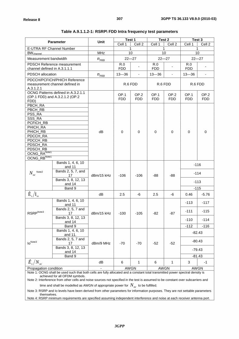
3GPP
307Release 8 3GPP TS 36.133 V8.9.0 (2010-03)
Table A.9.1.1.2-1: RSRP\ FDD Intra frequency test parameters
Parameter Unit Test 1 Test 2 Test 3 Cell 1 Cell 2 Cell 1 Cell 2 Cell 1 Cell 2
E-UTRA RF Channel Number 1 1 1 BWchannel MHz 10 10 10 Measurement bandwidth PRBn 22—27 22—27 22—27 PDSCH Reference measurement channel defined in A.3.1.1.1 R.0
FDD - R.0 FDD - R.0
FDD -
PDSCH allocation PRBn 13—36 - 13—36 - 13—36 - PDCCH/PCFICH/PHICH Reference measurement channel defined in A.3.1.2.1
R.6 FDD R.6 FDD R.6 FDD
OCNG Patterns defined in A.3.2.1.1 (OP.1 FDD) and A.3.2.1.2 (OP.2 FDD)
OP.1 FDD
OP.2 FDD
OP.1 FDD
OP.2 FDD
OP.1 FDD
OP.2 FDD
PBCH_RA
dB 0 0 0 0 0 0
PBCH_RB PSS_RA SSS_RA PCFICH_RB PHICH_RA PHICH_RB PDCCH_RA PDCCH_RB PDSCH_RA PDSCH_RB OCNG_RANote1 OCNG_RBNote1
ocN Note2
Bands 1, 4, 6, 10 and 11
dBm/15 kHz -106 -106 -88 -88
-116
Bands 2, 5, 7, and 17 -114
Bands 3, 8, 12, 13 and 14 -113
Band 9 -115
ots IÊ dB 2.5 -6 2.5 -6 0.46 -5.76
RSRPNote3
Bands 1, 4, 6, 10 and 11
dBm/15 kHz -100 -105 -82 -87
-113 -117
Bands 2, 5, 7 and 17 -111 -115
Bands 3, 8, 12, 13 and 14 -110 -114
Band 9 -112 -116
IoNote3
Bands 1, 4, 6, 10 and 11.
dBm/9 MHz -70 -70 -52 -52
-82.43
Bands 2, 5, 7 and 17 -80.43
Bands 3, 8, 12, 13 and 14 -79.43
Band 9 -81.43
ocs NÊ dB 6 1 6 1 3 -1
Propagation condition - AWGN AWGN AWGN Note 1: OCNG shall be used such that both cells are fully allocated and a constant total transmitted power spectral density is
achieved for all OFDM symbols. Note 2: Interference from other cells and noise sources not specified in the test is assumed to be constant over subcarriers and
time and shall be modelled as AWGN of appropriate power for ocN to be fulfilled. Note 3: RSRP and Io levels have been derived from other parameters for information purposes. They are not settable parameters
themselves. Note 4: RSRP minimum requirements are specified assuming independent interference and noise at each receiver antenna port.
3GPP
308Release 8 3GPP TS 36.133 V8.9.0 (2010-03)
A.9.1.1.3 Test Requirements
The RSRP measurement accuracy shall fulfil the requirements in section 9.1.2.
A.9.1.2 TDD Intra frequency case
A.9.1.2.1 Test Purpose and Environment
The purpose of this test is to verify that the RSRP measurement accuracy is within the specified limits. This test will verify the requirements in Section 9.1.2 for TDD intra frequency measurements.
A.9.1.2.2 Test parameters
In this set of test cases all cells are on the same carrier frequency. Both absolute and relative accuracy of RSRP intra frequency measurements are tested by using the parameters in Table A.9.1.2.2-1. In all test cases, Cell 1 is the serving cell and Cell 2 the target cell.
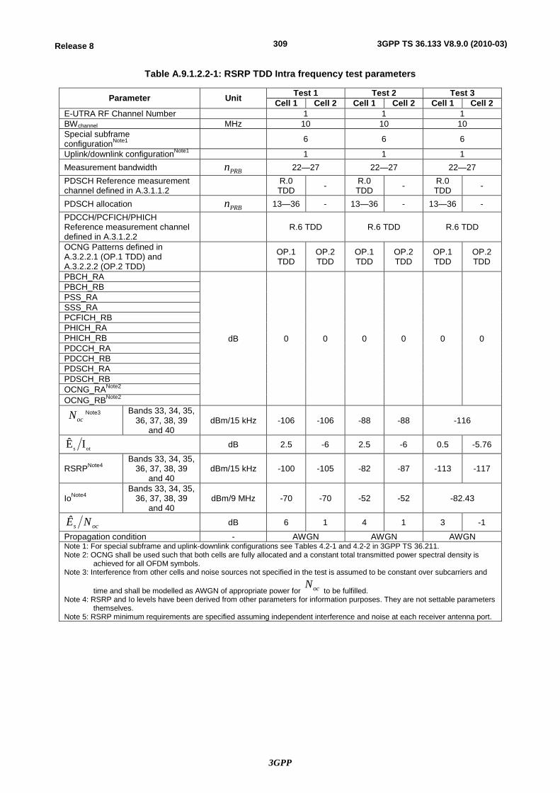
3GPP
309Release 8 3GPP TS 36.133 V8.9.0 (2010-03)
Table A.9.1.2.2-1: RSRP TDD Intra frequency test parameters
Parameter Unit Test 1 Test 2 Test 3 Cell 1 Cell 2 Cell 1 Cell 2 Cell 1 Cell 2
E-UTRA RF Channel Number 1 1 1 BWchannel MHz 10 10 10 Special subframe configurationNote1 6 6 6
Uplink/downlink configurationNote1 1 1 1 Measurement bandwidth PRBn 22—27 22—27 22—27 PDSCH Reference measurement channel defined in A.3.1.1.2 R.0
TDD - R.0 TDD - R.0
TDD -
PDSCH allocation PRBn 13—36 - 13—36 - 13—36 - PDCCH/PCFICH/PHICH Reference measurement channel defined in A.3.1.2.2
R.6 TDD R.6 TDD R.6 TDD
OCNG Patterns defined in A.3.2.2.1 (OP.1 TDD) and A.3.2.2.2 (OP.2 TDD)
OP.1 TDD
OP.2 TDD
OP.1 TDD
OP.2 TDD
OP.1 TDD
OP.2 TDD
PBCH_RA
dB 0 0 0 0 0 0
PBCH_RB PSS_RA SSS_RA PCFICH_RB PHICH_RA PHICH_RB PDCCH_RA PDCCH_RB PDSCH_RA PDSCH_RB OCNG_RANote2 OCNG_RBNote2
ocN Note3
Bands 33, 34, 35, 36, 37, 38, 39
and 40 dBm/15 kHz -106 -106 -88 -88 -116
ots IÊ dB 2.5 -6 2.5 -6 0.5 -5.76
RSRPNote4 Bands 33, 34, 35,
36, 37, 38, 39 and 40
dBm/15 kHz -100 -105 -82 -87 -113 -117
IoNote4 Bands 33, 34, 35,
36, 37, 38, 39 and 40
dBm/9 MHz -70 -70 -52 -52 -82.43
ocs NÊ dB 6 1 4 1 3 -1
Propagation condition - AWGN AWGN AWGN Note 1: For special subframe and uplink-downlink configurations see Tables 4.2-1 and 4.2-2 in 3GPP TS 36.211. Note 2: OCNG shall be used such that both cells are fully allocated and a constant total transmitted power spectral density is
achieved for all OFDM symbols. Note 3: Interference from other cells and noise sources not specified in the test is assumed to be constant over subcarriers and
time and shall be modelled as AWGN of appropriate power for ocN to be fulfilled.
Note 4: RSRP and Io levels have been derived from other parameters for information purposes. They are not settable parameters themselves.
Note 5: RSRP minimum requirements are specified assuming independent interference and noise at each receiver antenna port.
3GPP
310Release 8 3GPP TS 36.133 V8.9.0 (2010-03)
A.9.1.2.3 Test Requirements
The RSRP measurement accuracy shall fulfil the requirements in section 9.1.2.
A.9.1.3 FDD—FDD Inter frequency case
A.9.1.3.1 Test Purpose and Environment
The purpose of this test is to verify that the RSRP measurement accuracy is within the specified limits. This test will verify the requirements in Section 9.1.3 for FDD—FDD inter frequency measurements.
A.9.1.3.2 Test parameters
In this set of test cases the cells are on different carrier frequencies. Both absolute and relative accuracy of RSRP intra frequency measurements are tested by using the parameters in Table A.9.1.3.2-1 In all test cases, Cell 1 is the serving cell and Cell 2 the target cell. The inter frequency measurements are supported by a measurement gap.
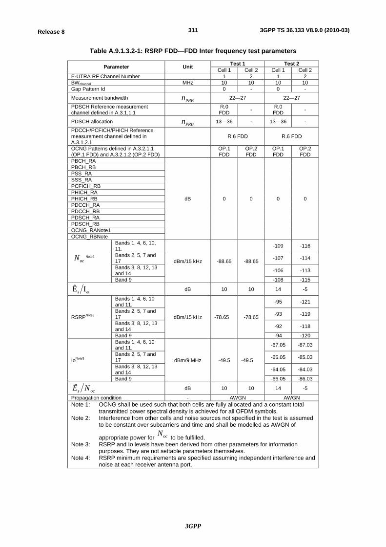
3GPP
311Release 8 3GPP TS 36.133 V8.9.0 (2010-03)
Table A.9.1.3.2-1: RSRP FDD—FDD Inter frequency test parameters
Parameter Unit Test 1 Test 2 Cell 1 Cell 2 Cell 1 Cell 2
E-UTRA RF Channel Number 1 2 1 2 BWchannel MHz 10 10 10 10 Gap Pattern Id 0 - 0 -
Measurement bandwidth PRBn 22—27 22—27
PDSCH Reference measurement channel defined in A.3.1.1.1 R.0
FDD - R.0 FDD -
PDSCH allocation PRBn 13—36 - 13—36 -
PDCCH/PCFICH/PHICH Reference measurement channel defined in A.3.1.2.1
R.6 FDD R.6 FDD
OCNG Patterns defined in A.3.2.1.1 (OP.1 FDD) and A.3.2.1.2 (OP.2 FDD) OP.1
FDD OP.2 FDD
OP.1 FDD
OP.2 FDD
PBCH_RA
dB 0 0 0 0
PBCH_RB PSS_RA SSS_RA PCFICH_RB PHICH_RA PHICH_RB PDCCH_RA PDCCH_RB PDSCH_RA PDSCH_RB OCNG_RANote1 OCNG_RBNote
ocN Note2
Bands 1, 4, 6, 10, 11.
dBm/15 kHz -88.65 -88.65
-109 -116
Bands 2, 5, 7 and 17 -107 -114
Bands 3, 8, 12, 13 and 14 -106 -113
Band 9 -108 -115
ots IÊ dB 10 10 14 -5
RSRPNote3
Bands 1, 4, 6, 10 and 11.
dBm/15 kHz -78.65 -78.65
-95 -121
Bands 2, 5, 7 and 17 -93 -119
Bands 3, 8, 12, 13 and 14 -92 -118
Band 9 -94 -120
IoNote3
Bands 1, 4, 6, 10 and 11.
dBm/9 MHz -49.5 -49.5
-67.05 -87.03
Bands 2, 5, 7 and 17 -65.05 -85.03
Bands 3, 8, 12, 13 and 14 -64.05 -84.03
Band 9 -66.05 -86.03
ocs NÊ dB 10 10 14 -5
Propagation condition - AWGN AWGN Note 1: OCNG shall be used such that both cells are fully allocated and a constant total
transmitted power spectral density is achieved for all OFDM symbols. Note 2: Interference from other cells and noise sources not specified in the test is assumed
to be constant over subcarriers and time and shall be modelled as AWGN of
appropriate power for ocN to be fulfilled.
Note 3: RSRP and Io levels have been derived from other parameters for information purposes. They are not settable parameters themselves.
Note 4: RSRP minimum requirements are specified assuming independent interference and noise at each receiver antenna port.

3GPP
312Release 8 3GPP TS 36.133 V8.9.0 (2010-03)
A.9.1.3.3 Test Requirements
The RSRP measurement accuracy shall fulfil the requirements in section 9.1.3.
A.9.1.4 TDD—TDD Inter frequency case
A.9.1.4.1 Test Purpose and Environment
The purpose of this test is to verify that the RSRP measurement accuracy is within the specified limits. This test will verify the requirements in Section 9.1.3 for TDD—TDD inter frequency measurements.
A.9.1.4.2 Test parameters
In this set of test cases the cells are on different carrier frequencies. Both absolute and relative accuracy of RSRP intra frequency measurements are tested by using the parameters in Table A.9.1.4.2-1. In all test cases, Cell 1 is the serving cell and Cell 2 the target cell. The inter frequency measurements are supported by a measurement gap.
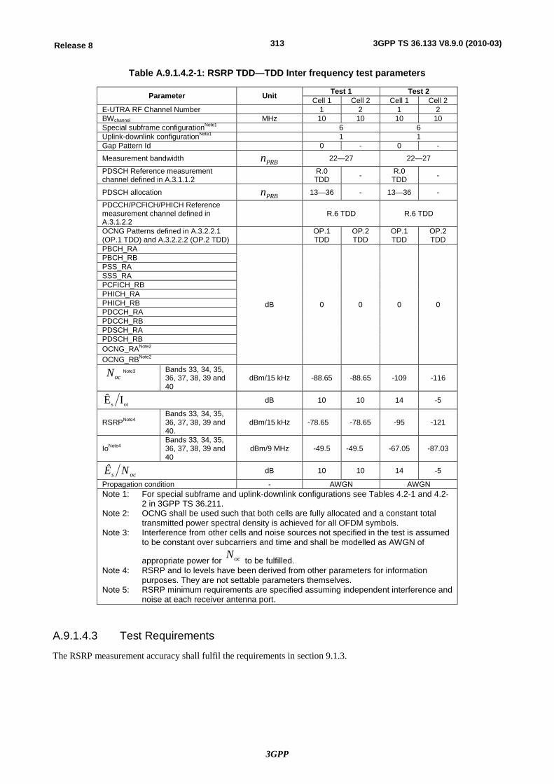
3GPP
313Release 8 3GPP TS 36.133 V8.9.0 (2010-03)
Table A.9.1.4.2-1: RSRP TDD—TDD Inter frequency test parameters
Parameter Unit Test 1 Test 2 Cell 1 Cell 2 Cell 1 Cell 2
E-UTRA RF Channel Number 1 2 1 2 BWchannel MHz 10 10 10 10 Special subframe configurationNote1 6 6 Uplink-downlink configurationNote1 1 1 Gap Pattern Id 0 - 0 -
Measurement bandwidth PRBn 22—27 22—27
PDSCH Reference measurement channel defined in A.3.1.1.2 R.0
TDD - R.0 TDD -
PDSCH allocation PRBn 13—36 - 13—36 -
PDCCH/PCFICH/PHICH Reference measurement channel defined in A.3.1.2.2
R.6 TDD R.6 TDD
OCNG Patterns defined in A.3.2.2.1 (OP.1 TDD) and A.3.2.2.2 (OP.2 TDD) OP.1
TDD OP.2 TDD
OP.1 TDD
OP.2 TDD
PBCH_RA
dB 0 0 0 0
PBCH_RB PSS_RA SSS_RA PCFICH_RB PHICH_RA PHICH_RB PDCCH_RA PDCCH_RB PDSCH_RA PDSCH_RB OCNG_RANote2 OCNG_RBNote2
ocN Note3
Bands 33, 34, 35, 36, 37, 38, 39 and 40
dBm/15 kHz -88.65 -88.65 -109 -116
ots IÊ dB 10 10 14 -5
RSRPNote4 Bands 33, 34, 35, 36, 37, 38, 39 and 40.
dBm/15 kHz -78.65 -78.65 -95 -121
IoNote4 Bands 33, 34, 35, 36, 37, 38, 39 and 40
dBm/9 MHz -49.5 -49.5 -67.05 -87.03
ocs NÊ dB 10 10 14 -5
Propagation condition - AWGN AWGN Note 1: For special subframe and uplink-downlink configurations see Tables 4.2-1 and 4.2-
2 in 3GPP TS 36.211. Note 2: OCNG shall be used such that both cells are fully allocated and a constant total
transmitted power spectral density is achieved for all OFDM symbols. Note 3: Interference from other cells and noise sources not specified in the test is assumed
to be constant over subcarriers and time and shall be modelled as AWGN of
appropriate power for ocN to be fulfilled.
Note 4: RSRP and Io levels have been derived from other parameters for information purposes. They are not settable parameters themselves.
Note 5: RSRP minimum requirements are specified assuming independent interference and noise at each receiver antenna port.
A.9.1.4.3 Test Requirements
The RSRP measurement accuracy shall fulfil the requirements in section 9.1.3.
3GPP
314Release 8 3GPP TS 36.133 V8.9.0 (2010-03)
A.9.2 RSRQ
A.9.2.1 FDD Intra frequency case
A.9.2.1.1 Test Purpose and Environment
The purpose of this test is to verify that the RSRQ measurement accuracy is within the specified limits. This test will verify the requirements in Section 9.1.5.
A.9.2.1.2 Test parameters
In this test case all cells are on the same carrier frequency. The absolute accuracy of RSRQ intra frequency measurement is tested by using the parameters in Table A.9.2.1.2-1. In all test cases, Cell 1 is the serving cell and Cell 2 the target cell.
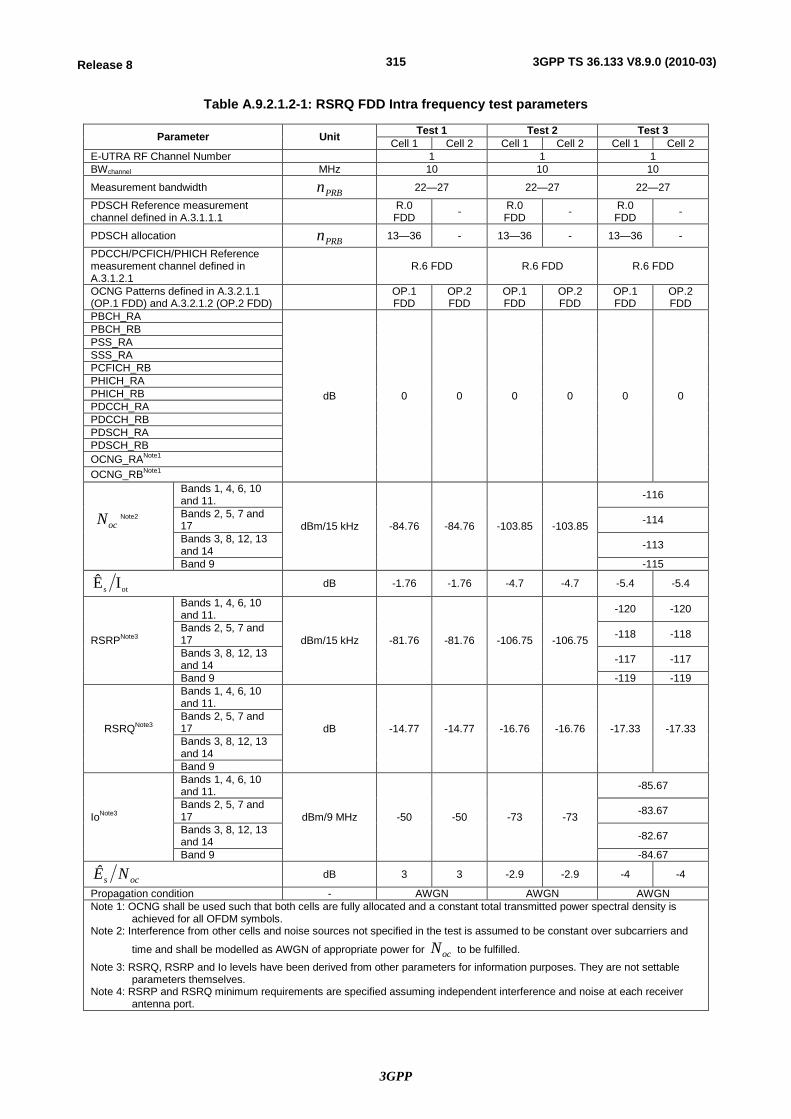
3GPP
315Release 8 3GPP TS 36.133 V8.9.0 (2010-03)
Table A.9.2.1.2-1: RSRQ FDD Intra frequency test parameters
Parameter Unit Test 1 Test 2 Test 3 Cell 1 Cell 2 Cell 1 Cell 2 Cell 1 Cell 2
E-UTRA RF Channel Number 1 1 1 BWchannel MHz 10 10 10
Measurement bandwidth PRBn 22—27 22—27 22—27
PDSCH Reference measurement channel defined in A.3.1.1.1 R.0
FDD - R.0 FDD - R.0
FDD -
PDSCH allocation PRBn 13—36 - 13—36 - 13—36 -
PDCCH/PCFICH/PHICH Reference measurement channel defined in A.3.1.2.1
R.6 FDD R.6 FDD R.6 FDD
OCNG Patterns defined in A.3.2.1.1 (OP.1 FDD) and A.3.2.1.2 (OP.2 FDD) OP.1
FDD OP.2 FDD
OP.1 FDD
OP.2 FDD
OP.1 FDD
OP.2 FDD
PBCH_RA
dB 0 0 0 0 0 0
PBCH_RB PSS_RA SSS_RA PCFICH_RB PHICH_RA PHICH_RB PDCCH_RA PDCCH_RB PDSCH_RA PDSCH_RB OCNG_RANote1 OCNG_RBNote1
ocN Note2
Bands 1, 4, 6, 10 and 11.
dBm/15 kHz -84.76 -84.76 -103.85 -103.85
-116
Bands 2, 5, 7 and 17 -114
Bands 3, 8, 12, 13 and 14 -113
Band 9 -115
ots IÊ dB -1.76 -1.76 -4.7 -4.7 -5.4 -5.4
RSRPNote3
Bands 1, 4, 6, 10 and 11.
dBm/15 kHz -81.76 -81.76 -106.75 -106.75
-120 -120
Bands 2, 5, 7 and 17 -118 -118
Bands 3, 8, 12, 13 and 14 -117 -117
Band 9 -119 -119
RSRQNote3
Bands 1, 4, 6, 10 and 11.
dB -14.77 -14.77 -16.76 -16.76 -17.33 -17.33 Bands 2, 5, 7 and 17 Bands 3, 8, 12, 13 and 14 Band 9
IoNote3
Bands 1, 4, 6, 10 and 11.
dBm/9 MHz -50 -50 -73 -73
-85.67
Bands 2, 5, 7 and 17 -83.67
Bands 3, 8, 12, 13 and 14 -82.67
Band 9 -84.67
ocs NÊ dB 3 3 -2.9 -2.9 -4 -4
Propagation condition - AWGN AWGN AWGN Note 1: OCNG shall be used such that both cells are fully allocated and a constant total transmitted power spectral density is
achieved for all OFDM symbols. Note 2: Interference from other cells and noise sources not specified in the test is assumed to be constant over subcarriers and
time and shall be modelled as AWGN of appropriate power for ocN to be fulfilled. Note 3: RSRQ, RSRP and Io levels have been derived from other parameters for information purposes. They are not settable
parameters themselves. Note 4: RSRP and RSRQ minimum requirements are specified assuming independent interference and noise at each receiver
antenna port.

3GPP
316Release 8 3GPP TS 36.133 V8.9.0 (2010-03)
A.9.2.1.3 Test Requirements
The RSRQ measurement accuracy shall fulfil the requirements in Section 9.1.5.
A.9.2.2 TDD Intra frequency case
A.9.2.2.1 Test Purpose and Environment
The purpose of this test is to verify that the RSRQ measurement accuracy is within the specified limits. This test will verify the requirements in Section 9.1.5.
A.9.2.2.2 Test parameters
In this test case all cells are on the same carrier frequency. The absolute accuracy of RSRQ intra frequency measurement is tested by using the parameters in Table A.9.2.2.2-1. In all test cases, Cell 1 is the serving cell and Cell 2 the target cell.
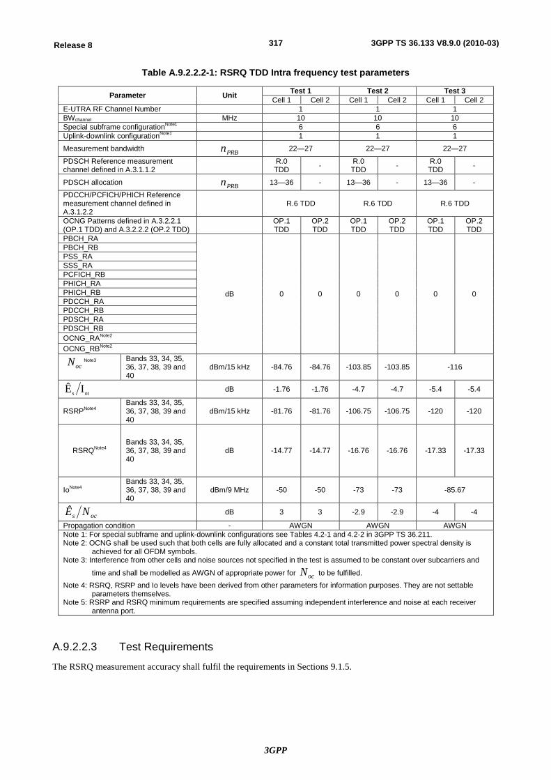
3GPP
317Release 8 3GPP TS 36.133 V8.9.0 (2010-03)
Table A.9.2.2.2-1: RSRQ TDD Intra frequency test parameters
Parameter Unit Test 1 Test 2 Test 3 Cell 1 Cell 2 Cell 1 Cell 2 Cell 1 Cell 2
E-UTRA RF Channel Number 1 1 1 BWchannel MHz 10 10 10 Special subframe configurationNote1 6 6 6 Uplink-downlink configurationNote1 1 1 1
Measurement bandwidth PRBn 22—27 22—27 22—27
PDSCH Reference measurement channel defined in A.3.1.1.2 R.0
TDD - R.0 TDD - R.0
TDD -
PDSCH allocation PRBn 13—36 - 13—36 - 13—36 -
PDCCH/PCFICH/PHICH Reference measurement channel defined in A.3.1.2.2
R.6 TDD R.6 TDD R.6 TDD
OCNG Patterns defined in A.3.2.2.1 (OP.1 TDD) and A.3.2.2.2 (OP.2 TDD) OP.1
TDD OP.2 TDD
OP.1 TDD
OP.2 TDD
OP.1 TDD
OP.2 TDD
PBCH_RA
dB 0 0 0 0 0 0
PBCH_RB PSS_RA SSS_RA PCFICH_RB PHICH_RA PHICH_RB PDCCH_RA PDCCH_RB PDSCH_RA PDSCH_RB OCNG_RANote2 OCNG_RBNote2
ocN Note3
Bands 33, 34, 35, 36, 37, 38, 39 and 40
dBm/15 kHz -84.76 -84.76 -103.85 -103.85 -116
ots IÊ dB -1.76 -1.76 -4.7 -4.7 -5.4 -5.4
RSRPNote4 Bands 33, 34, 35, 36, 37, 38, 39 and 40
dBm/15 kHz -81.76 -81.76 -106.75 -106.75 -120 -120
RSRQNote4 Bands 33, 34, 35, 36, 37, 38, 39 and 40
dB -14.77 -14.77 -16.76 -16.76 -17.33 -17.33
IoNote4 Bands 33, 34, 35, 36, 37, 38, 39 and 40
dBm/9 MHz -50 -50 -73 -73 -85.67
ocs NÊ dB 3 3 -2.9 -2.9 -4 -4
Propagation condition - AWGN AWGN AWGN Note 1: For special subframe and uplink-downlink configurations see Tables 4.2-1 and 4.2-2 in 3GPP TS 36.211. Note 2: OCNG shall be used such that both cells are fully allocated and a constant total transmitted power spectral density is
achieved for all OFDM symbols. Note 3: Interference from other cells and noise sources not specified in the test is assumed to be constant over subcarriers and
time and shall be modelled as AWGN of appropriate power for ocN to be fulfilled. Note 4: RSRQ, RSRP and Io levels have been derived from other parameters for information purposes. They are not settable
parameters themselves. Note 5: RSRP and RSRQ minimum requirements are specified assuming independent interference and noise at each receiver
antenna port.
A.9.2.2.3 Test Requirements
The RSRQ measurement accuracy shall fulfil the requirements in Sections 9.1.5.
3GPP
318Release 8 3GPP TS 36.133 V8.9.0 (2010-03)
A.9.2.3 FDD—FDD Inter frequency case
A.9.2.3.1 Test Purpose and Environment
The purpose of this test is to verify that the RSRQ measurement accuracy is within the specified limits. This test will verify the requirements in Section 9.1.6.
A.9.2.3.2 Test parameters
In this test case the two cells are on different carrier frequencies and measurement gaps are provided. Both RSRQ inter frequency absolute and relative accuracy requirements are tested by using test parameters in Table A.9.2.3.2-1. In all tests, Cell 1 is the serving cell and Cell 2 the target cell.
3GPP
319Release 8 3GPP TS 36.133 V8.9.0 (2010-03)
Table A.9.2.3.2-1: RSRQ FDD—FDD Inter frequency test parameters
Parameter Unit Test 1 Test 2 Test 3 Cell 1 Cell 2 Cell 1 Cell 2 Cell 1 Cell 2
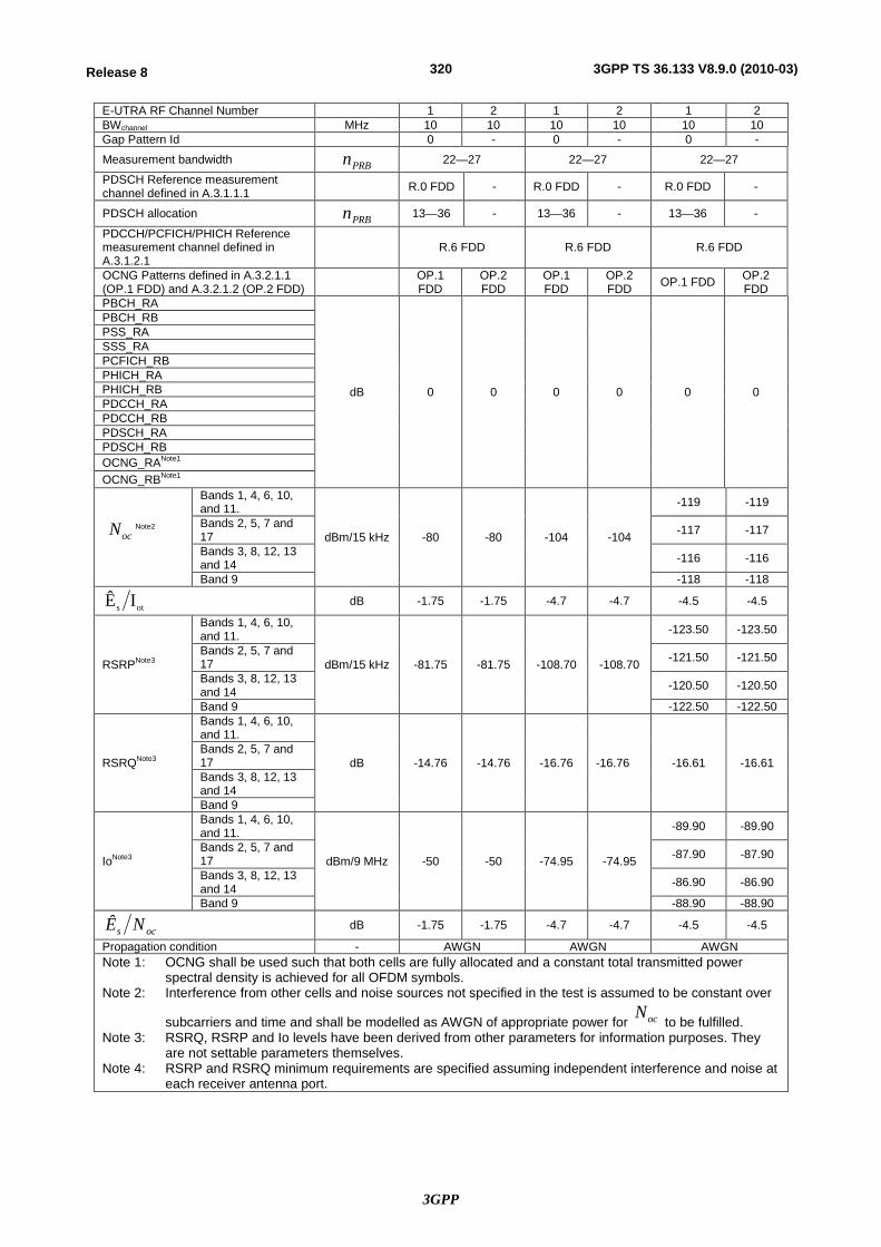
3GPP
320Release 8 3GPP TS 36.133 V8.9.0 (2010-03)
E-UTRA RF Channel Number 1 2 1 2 1 2 BWchannel MHz 10 10 10 10 10 10 Gap Pattern Id 0 - 0 - 0 -
Measurement bandwidth PRBn 22—27 22—27 22—27
PDSCH Reference measurement channel defined in A.3.1.1.1 R.0 FDD - R.0 FDD - R.0 FDD -
PDSCH allocation PRBn 13—36 - 13—36 - 13—36 -
PDCCH/PCFICH/PHICH Reference measurement channel defined in A.3.1.2.1
R.6 FDD R.6 FDD R.6 FDD
OCNG Patterns defined in A.3.2.1.1 (OP.1 FDD) and A.3.2.1.2 (OP.2 FDD) OP.1
FDD OP.2 FDD
OP.1 FDD
OP.2 FDD OP.1 FDD OP.2
FDD PBCH_RA
dB 0 0 0 0 0 0
PBCH_RB PSS_RA SSS_RA PCFICH_RB PHICH_RA PHICH_RB PDCCH_RA PDCCH_RB PDSCH_RA PDSCH_RB OCNG_RANote1 OCNG_RBNote1
ocN Note2
Bands 1, 4, 6, 10, and 11.
dBm/15 kHz -80 -80 -104 -104
-119 -119
Bands 2, 5, 7 and 17 -117 -117
Bands 3, 8, 12, 13 and 14 -116 -116
Band 9 -118 -118
ots IÊ dB -1.75 -1.75 -4.7 -4.7 -4.5 -4.5
RSRPNote3
Bands 1, 4, 6, 10, and 11.
dBm/15 kHz -81.75 -81.75 -108.70 -108.70
-123.50 -123.50
Bands 2, 5, 7 and 17 -121.50 -121.50
Bands 3, 8, 12, 13 and 14 -120.50 -120.50
Band 9 -122.50 -122.50
RSRQNote3
Bands 1, 4, 6, 10, and 11.
dB -14.76 -14.76 -16.76 -16.76 -16.61 -16.61 Bands 2, 5, 7 and 17 Bands 3, 8, 12, 13 and 14 Band 9
IoNote3
Bands 1, 4, 6, 10, and 11.
dBm/9 MHz -50 -50 -74.95 -74.95
-89.90 -89.90
Bands 2, 5, 7 and 17 -87.90 -87.90
Bands 3, 8, 12, 13 and 14 -86.90 -86.90
Band 9 -88.90 -88.90
ocs NÊ dB -1.75 -1.75 -4.7 -4.7 -4.5 -4.5
Propagation condition - AWGN AWGN AWGN Note 1: OCNG shall be used such that both cells are fully allocated and a constant total transmitted power
spectral density is achieved for all OFDM symbols. Note 2: Interference from other cells and noise sources not specified in the test is assumed to be constant over
subcarriers and time and shall be modelled as AWGN of appropriate power for ocN to be fulfilled.
Note 3: RSRQ, RSRP and Io levels have been derived from other parameters for information purposes. They are not settable parameters themselves.
Note 4: RSRP and RSRQ minimum requirements are specified assuming independent interference and noise at each receiver antenna port.
3GPP
321Release 8 3GPP TS 36.133 V8.9.0 (2010-03)
A.9.2.3.3 Test Requirements
The RSRQ measurement accuracy shall fulfil the requirements in Section 9.1.6.
A.9.2.4 TDD—TDD Inter frequency case
A.9.2.4.1 Test Purpose and Environment
The purpose of this test is to verify that the RSRQ measurement accuracy is within the specified limits. This test will verify the requirements in Section 9.1.6.
A.9.2.4.2 Test parameters
In this test case the two cells are on different carrier frequencies and measurement gaps are provided. Both RSRQ inter frequency absolute and relative accuracy requirements are tested by using test parameters in Table A.9.2.4.2-1. In all tests, Cell 1 is the serving cell and Cell 2 the target cell.
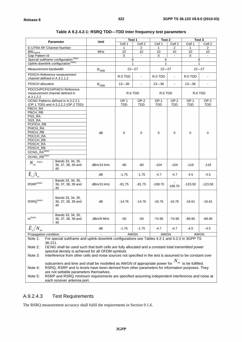
3GPP
322Release 8 3GPP TS 36.133 V8.9.0 (2010-03)
Table A 9.2.4.2-1: RSRQ TDD—TDD Inter frequency test parameters
Parameter Unit Test 1 Test 2 Test 3 Cell 1 Cell 2 Cell 1 Cell 2 Cell 1 Cell 2
E-UTRA RF Channel Number 1 2 1 2 1 2 BWchannel MHz 10 10 10 10 10 10 Gap Pattern Id 0 - 0 - 0 - Special subframe configuration Note1 6 6 6 Uplink-downlink configuration Note1 1 1 1
Measurement bandwidth PRBn 22—27 22—27 22—27
PDSCH Reference measurement channel defined in A.3.1.1.2 R.0 TDD - R.0 TDD - R.0 TDD -
PDSCH allocation PRBn 13—36 - 13—36 - 13—36 -
PDCCH/PCFICH/PHICH Reference measurement channel defined in A.3.1.2.2
R.6 TDD R.6 TDD R.6 TDD
OCNG Patterns defined in A.3.2.2.1 (OP.1 TDD) and A.3.2.2.2 (OP.2 TDD) OP.1
TDD OP.2 TDD
OP.1 TDD
OP.2 TDD
OP.1 TDD
OP.2 TDD
PBCH_RA
dB 0 0 0 0 0 0
PBCH_RB PSS_RA SSS_RA PCFICH_RB PHICH_RA PHICH_RB PDCCH_RA PDCCH_RB PDSCH_RA PDSCH_RB OCNG_RANote2 OCNG_RBNote2
ocN Note3
Bands 33, 34, 35, 36, 37, 38, 39 and 40
dBm/15 kHz -80 -80 -104 -104 -119 -119
ots IÊ dB -1.75 -1.75 -4.7 -4.7 -4.5 -4.5
RSRPNote4 Bands 33, 34, 35, 36, 37, 38, 39 and 40
dBm/15 kHz -81.75 -81.75 -108.70 -108.70 -123.50 -123.50
RSRQNote4 Bands 33, 34, 35, 36, 37, 38, 39 and 40
dB -14.76 -14.76 -16.76 -16.76 -16.61 -16.61
IoNote4 Bands 33, 34, 35, 36, 37, 38, 39 and 40
dBm/9 MHz -50 -50 -74.95 -74.95 -89.90 -89.90
ocs NÊ dB -1.75 -1.75 -4.7 -4.7 -4.5 -4.5
Propagation condition - AWGN AWGN AWGN Note 1: For special subframe and uplink-downlink configurations see Tables 4.2-1 and 4.2-2 in 3GPP TS
36.211. Note 2: OCNG shall be used such that both cells are fully allocated and a constant total transmitted power
spectral density is achieved for all OFDM symbols. Note 3: Interference from other cells and noise sources not specified in the test is assumed to be constant over
subcarriers and time and shall be modelled as AWGN of appropriate power for ocN to be fulfilled.
Note 4: RSRQ, RSRP and Io levels have been derived from other parameters for information purposes. They are not settable parameters themselves.
Note 5: RSRP and RSRQ minimum requirements are specified assuming independent interference and noise at each receiver antenna port.
A.9.2.4.3 Test Requirements
The RSRQ measurement accuracy shall fulfil the requirements in Section 9.1.6.
3GPP
323Release 8 3GPP TS 36.133 V8.9.0 (2010-03)
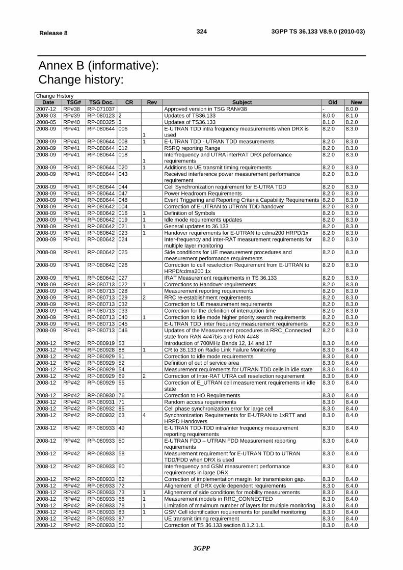
3GPP
324Release 8 3GPP TS 36.133 V8.9.0 (2010-03)
Annex B (informative): Change history:
Change History Date TSG# TSG Doc. CR Rev Subject Old New
2007-12 RP#38 RP-071037 Approved version in TSG RAN#38 - 8.0.0 2008-03 RP#39 RP-080123 2 Updates of TS36.133 8.0.0 8.1.0 2008-05 RP#40 RP-080325 3 Updates of TS36.133 8.1.0 8.2.0 2008-09 RP#41 RP-080644 006
1 E-UTRAN TDD intra frequency measurements when DRX is used
8.2.0 8.3.0
2008-09 RP#41 RP-080644 008 1 E-UTRAN TDD - UTRAN TDD measurements 8.2.0 8.3.0 2008-09 RP#41 RP-080644 012 RSRQ reporting Range 8.2.0 8.3.0 2008-09 RP#41 RP-080644 018
1 Interfrequency and UTRA interRAT DRX peformance requirements
8.2.0 8.3.0
2008-09 RP#41 RP-080644 020 1 Additions to UE transmit timing requirements 8.2.0 8.3.0 2008-09 RP#41 RP-080644 043
Received interference power measurement performance requirement
8.2.0 8.3.0
2008-09 RP#41 RP-080644 044 Cell Synchronization requirement for E-UTRA TDD 8.2.0 8.3.0 2008-09 RP#41 RP-080644 047 Power Headroom Requirements 8.2.0 8.3.0 2008-09 RP#41 RP-080644 048 Event Triggering and Reporting Criteria Capability Requirements 8.2.0 8.3.0 2008-09 RP#41 RP-080642 004 Correction of E-UTRAN to UTRAN TDD handover 8.2.0 8.3.0 2008-09 RP#41 RP-080642 016 1 Definition of Symbols 8.2.0 8.3.0 2008-09 RP#41 RP-080642 019 1 Idle mode requirements updates 8.2.0 8.3.0 2008-09 RP#41 RP-080642 021 1 General updates to 36.133 8.2.0 8.3.0 2008-09 RP#41 RP-080642 023 1 Handover requirements for E-UTRAN to cdma200 HRPD/1x 8.2.0 8.3.0 2008-09 RP#41 RP-080642 024
Inter-frequency and inter-RAT measurement requirements for multiple layer monitoring
8.2.0 8.3.0
2008-09 RP#41 RP-080642 025
Side conditions for UE measurement procedures and measurement performance requirements
8.2.0 8.3.0
2008-09 RP#41 RP-080642 026
Correction to cell reselection Requirement from E-UTRAN to HRPD/cdma200 1x
8.2.0 8.3.0
2008-09 RP#41 RP-080642 027 IRAT Measurement requirements in TS 36.133 8.2.0 8.3.0 2008-09 RP#41 RP-080713 022 1 Corrections to Handover requirements 8.2.0 8.3.0 2008-09 RP#41 RP-080713 028 Measurement reporting requirements 8.2.0 8.3.0 2008-09 RP#41 RP-080713 029 2 RRC re-establishment requirements 8.2.0 8.3.0 2008-09 RP#41 RP-080713 032 Correction to UE measurement requirements 8.2.0 8.3.0 2008-09 RP#41 RP-080713 033 Correction for the definition of interruption time 8.2.0 8.3.0 2008-09 RP#41 RP-080713 040 1 Correction to idle mode higher priority search requirements 8.2.0 8.3.0 2008-09 RP#41 RP-080713 045 E-UTRAN TDD inter frequency measurement requirements 8.2.0 8.3.0 2008-09 RP#41 RP-080713 046
Updates of the Measurement procedures in RRC_Connected state from RAN 4#47bis and RAN 4#48
8.2.0 8.3.0
2008-12 RP#42 RP-080919 53 Introduction of 700MHz Bands 12, 14 and 17 8.3.0 8.4.0 2008-12 RP#42 RP-080928 88 1 CR to 36.133 on Radio Link Failure Monitoring 8.3.0 8.4.0 2008-12 RP#42 RP-080929 51 Correction to idle mode requirements 8.3.0 8.4.0 2008-12 RP#42 RP-080929 52 Definition of out of service area 8.3.0 8.4.0 2008-12 RP#42 RP-080929 54 Measurement requirements for UTRAN TDD cells in idle state 8.3.0 8.4.0 2008-12 RP#42 RP-080929 69 2 Correction of Inter-RAT UTRA cell reselection requirement 8.3.0 8.4.0 2008-12 RP#42 RP-080929 55 Correction of E_UTRAN cell measurement requirements in idle
state 8.3.0 8.4.0
2008-12 RP#42 RP-080930 76 Correction to HO Requirements 8.3.0 8.4.0 2008-12 RP#42 RP-080931 71 Random access requirements 8.3.0 8.4.0 2008-12 RP#42 RP-080932 85 Cell phase synchronization error for large cell 8.3.0 8.4.0 2008-12 RP#42 RP-080932 63 4 Synchronization Requirements for E-UTRAN to 1xRTT and
HRPD Handovers 8.3.0 8.4.0
2008-12 RP#42 RP-080933 49 E-UTRAN TDD-TDD intra/inter frequency measurement reporting requirements
8.3.0 8.4.0
2008-12 RP#42 RP-080933 50 E-UTRAN FDD – UTRAN FDD Measurement reporting requirements
8.3.0 8.4.0
2008-12 RP#42 RP-080933 58 Measurement requirement for E-UTRAN TDD to UTRAN TDD/FDD when DRX is used
8.3.0 8.4.0
2008-12 RP#42 RP-080933 60 Interfrequency and GSM measurement performance requirements in large DRX
8.3.0 8.4.0
2008-12 RP#42 RP-080933 62 Correction of implementation margin for transmission gap. 8.3.0 8.4.0 2008-12 RP#42 RP-080933 72 Alignement of DRX cycle dependent requirements 8.3.0 8.4.0 2008-12 RP#42 RP-080933 73 1 Alignement of side conditions for mobility measurements 8.3.0 8.4.0 2008-12 RP#42 RP-080933 66 1 Measurement models in RRC_CONNECTED 8.3.0 8.4.0 2008-12 RP#42 RP-080933 78 1 Limitation of maximum number of layers for multiple monitoring 8.3.0 8.4.0 2008-12 RP#42 RP-080933 83 1 GSM Cell identification requirements for parallel monitoring 8.3.0 8.4.0 2008-12 RP#42 RP-080933 87 UE transmit timing requirement 8.3.0 8.4.0 2008-12 RP#42 RP-080933 56 Correction of TS 36.133 section 8.1.2.1.1. 8.3.0 8.4.0
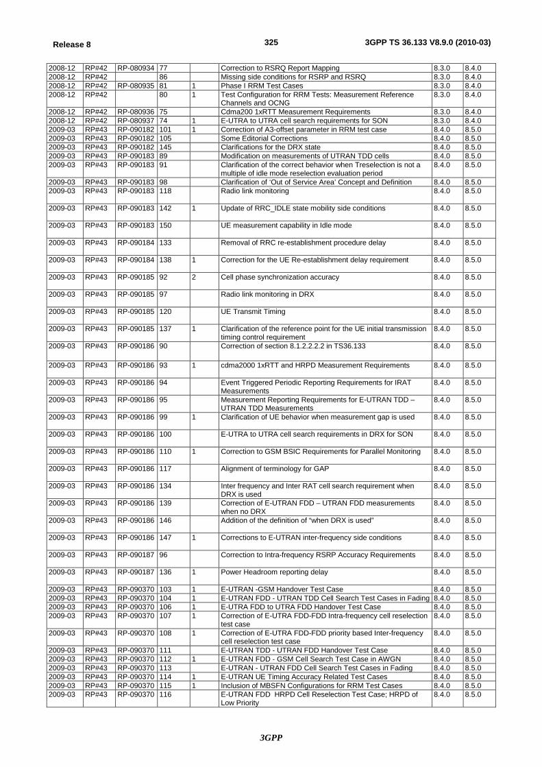
3GPP
325Release 8 3GPP TS 36.133 V8.9.0 (2010-03)
2008-12 RP#42 RP-080934 77 Correction to RSRQ Report Mapping 8.3.0 8.4.0 2008-12 RP#42 86 Missing side conditions for RSRP and RSRQ 8.3.0 8.4.0 2008-12 RP#42 RP-080935 81 1 Phase I RRM Test Cases 8.3.0 8.4.0 2008-12 RP#42 80 1 Test Configuration for RRM Tests: Measurement Reference
Channels and OCNG 8.3.0 8.4.0
2008-12 RP#42 RP-080936 75 Cdma200 1xRTT Measurement Requirements 8.3.0 8.4.0 2008-12 RP#42 RP-080937 74 1 E-UTRA to UTRA cell search requirements for SON 8.3.0 8.4.0 2009-03 RP#43 RP-090182 101 1 Correction of A3-offset parameter in RRM test case 8.4.0 8.5.0 2009-03 RP#43 RP-090182 105 Some Editorial Corrections 8.4.0 8.5.0 2009-03 RP#43 RP-090182 145 Clarifications for the DRX state 8.4.0 8.5.0 2009-03 RP#43 RP-090183 89 Modification on measurements of UTRAN TDD cells 8.4.0 8.5.0 2009-03 RP#43 RP-090183 91 Clarification of the correct behavior when Treselection is not a
multiple of idle mode reselection evaluation period 8.4.0 8.5.0
2009-03 RP#43 RP-090183 98 Clarification of ‘Out of Service Area’ Concept and Definition 8.4.0 8.5.0 2009-03 RP#43 RP-090183 118
Radio link monitoring 8.4.0 8.5.0
2009-03 RP#43 RP-090183 142
1 Update of RRC_IDLE state mobility side conditions 8.4.0 8.5.0
2009-03 RP#43 RP-090183 150
UE measurement capability in Idle mode 8.4.0 8.5.0
2009-03 RP#43 RP-090184 133
Removal of RRC re-establishment procedure delay 8.4.0 8.5.0
2009-03 RP#43 RP-090184 138
1 Correction for the UE Re-establishment delay requirement 8.4.0 8.5.0
2009-03 RP#43 RP-090185 92
2 Cell phase synchronization accuracy 8.4.0 8.5.0
2009-03 RP#43 RP-090185 97
Radio link monitoring in DRX 8.4.0 8.5.0
2009-03 RP#43 RP-090185 120
UE Transmit Timing 8.4.0 8.5.0
2009-03 RP#43 RP-090185 137
1 Clarification of the reference point for the UE initial transmission timing control requirement
8.4.0 8.5.0
2009-03 RP#43 RP-090186 90
Correction of section 8.1.2.2.2.2 in TS36.133 8.4.0 8.5.0
2009-03 RP#43 RP-090186 93
1 cdma2000 1xRTT and HRPD Measurement Requirements 8.4.0 8.5.0
2009-03 RP#43 RP-090186 94
Event Triggered Periodic Reporting Requirements for IRAT Measurements
8.4.0 8.5.0
2009-03 RP#43 RP-090186 95
Measurement Reporting Requirements for E-UTRAN TDD – UTRAN TDD Measurements
8.4.0 8.5.0
2009-03 RP#43 RP-090186 99
1 Clarification of UE behavior when measurement gap is used 8.4.0 8.5.0
2009-03 RP#43 RP-090186 100
E-UTRA to UTRA cell search requirements in DRX for SON 8.4.0 8.5.0
2009-03 RP#43 RP-090186 110
1 Correction to GSM BSIC Requirements for Parallel Monitoring 8.4.0 8.5.0
2009-03 RP#43 RP-090186 117
Alignment of terminology for GAP 8.4.0 8.5.0
2009-03 RP#43 RP-090186 134
Inter frequency and Inter RAT cell search requirement when DRX is used
8.4.0 8.5.0
2009-03 RP#43 RP-090186 139
Correction of E-UTRAN FDD – UTRAN FDD measurements when no DRX
8.4.0 8.5.0
2009-03 RP#43 RP-090186 146
Addition of the definition of “when DRX is used” 8.4.0 8.5.0
2009-03 RP#43 RP-090186 147
1 Corrections to E-UTRAN inter-frequency side conditions 8.4.0 8.5.0
2009-03 RP#43 RP-090187 96
Correction to Intra-frequency RSRP Accuracy Requirements 8.4.0 8.5.0
2009-03 RP#43 RP-090187 136
1 Power Headroom reporting delay 8.4.0 8.5.0
2009-03 RP#43 RP-090370 103 1 E-UTRAN -GSM Handover Test Case 8.4.0 8.5.0 2009-03 RP#43 RP-090370 104 1 E-UTRAN FDD - UTRAN TDD Cell Search Test Cases in Fading 8.4.0 8.5.0 2009-03 RP#43 RP-090370 106 1 E-UTRA FDD to UTRA FDD Handover Test Case 8.4.0 8.5.0 2009-03 RP#43 RP-090370 107 1 Correction of E-UTRA FDD-FDD Intra-frequency cell reselection
test case 8.4.0 8.5.0
2009-03 RP#43 RP-090370 108 1 Correction of E-UTRA FDD-FDD priority based Inter-frequency cell reselection test case
8.4.0 8.5.0
2009-03 RP#43 RP-090370 111 E-UTRAN TDD - UTRAN FDD Handover Test Case 8.4.0 8.5.0 2009-03 RP#43 RP-090370 112 1 E-UTRAN FDD - GSM Cell Search Test Case in AWGN 8.4.0 8.5.0 2009-03 RP#43 RP-090370 113 E-UTRAN - UTRAN FDD Cell Search Test Cases in Fading 8.4.0 8.5.0 2009-03 RP#43 RP-090370 114 1 E-UTRAN UE Timing Accuracy Related Test Cases 8.4.0 8.5.0 2009-03 RP#43 RP-090370 115 1 Inclusion of MBSFN Configurations for RRM Test Cases 8.4.0 8.5.0 2009-03 RP#43 RP-090370 116 E-UTRAN FDD HRPD Cell Reselection Test Case; HRPD of
Low Priority 8.4.0 8.5.0
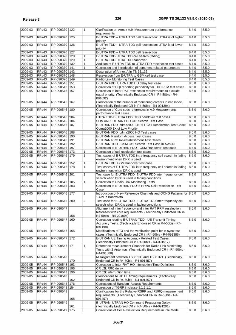
3GPP
326Release 8 3GPP TS 36.133 V8.9.0 (2010-03)
2009-03 RP#43 RP-090370 122 1 Clarification on Annex A.9: Measurement performance requirements
8.4.0 8.5.0
2009-03 RP#43 RP-090370 125 E-UTRA TDD – UTRA TDD cell reselection: UTRA is of higher priority
8.4.0 8.5.0
2009-03 RP#43 RP-090370 126 E-UTRA TDD – UTRA TDD cell reselection: UTRA is of lower priority
8.4.0 8.5.0
2009-03 RP#43 RP-090370 127 E-UTRA FDD – UTRA TDD cell reselection 8.4.0 8.5.0 2009-03 RP#43 RP-090370 128 1 E-UTRA TDD-UTRA TDD cell search (fading) 8.4.0 8.5.0 2009-03 RP#43 RP-090370 129 1 E-UTRA TDD-UTRA TDD handover 8.4.0 8.5.0 2009-03 RP#43 RP-090370 132 1 Addition of E-UTRA FDD to UTRA FDD reselection test cases 8.4.0 8.5.0 2009-03 RP#43 RP-090370 141 1 Correction and introduction of some test related parameters 8.4.0 8.5.0 2009-03 RP#43 RP-090370 143 Description of Annex A in TS 36.133 8.4.0 8.5.0 2009-03 RP#43 RP-090370 148 Reselection from E-UTRA to GSM cell test case 8.4.0 8.5.0 2009-03 RP#43 RP-090370 149 Radio Link Monitoring Test Cases 8.4.0 8.5.0 2009-05 RP#44 RP-090546 151 E-UTRA FDD UTRA TDD HO delay test case 8.5.0 8.6.0 2009-05 RP#44 RP-090546 153 Correction of CQI reporting periodicity for TDD RLM test cases 8.5.0 8.6.0 2009-05 RP#44 RP-090546 157 Correction to inter RAT reselection requirements to exclude
equal priority. (Technically Endorsed CR in R4-50bis - R4-091092)
8.5.0 8.6.0
2009-05 RP#44 RP-090546 167 Clarification of the number of monitoring carriers in idle mode. (Technically Endorsed CR in R4-50bis - R4-091394)
8.5.0 8.6.0
2009-05 RP#44 RP-090546 180 Correction of Core spec references in A.9 Measurements performance test cases
8.5.0 8.6.0
2009-05 RP#44 RP-090546 984 UTRA FDD-E-UTRA FDD/ TDD handover test cases 8.5.0 8.6.0 2009-05 RP#44 RP-090546 184 SON ANR UTRAN FDD Cell Search Test Case 8.5.0 8.6.0 2009-05 RP#44 RP-090546 187 E-UTRAN FDD cdma2000 1x RTT Cell Reselection Test Case;
Cdma2000 1X of Low Priority 8.5.0 8.6.0
2009-05 RP#44 RP-090546 188 E-UTRAN FDD cdma2000 HO Test cases 8.5.0 8.6.0 2009-05 RP#44 RP-090546 190 E-UTRAN Random Access Test Cases 8.5.0 8.6.0 2009-05 RP#44 RP-090546 191 E-UTRAN RRC Re-establishment Test Cases 8.5.0 8.6.0 2009-05 RP#44 RP-090546 192 E-UTRAN TDD - GSM Cell Search Test Case in AWGN 8.5.0 8.6.0 2009-05 RP#44 RP-090546 197 Correction to E-UTRAN FDD - GSM Handover Test case 8.5.0 8.6.0 2009-05 RP#44 RP-090546 173 1 Correction of cell reselection test cases 8.5.0 8.6.0 2009-05 RP#44 RP-090546 179 1 Test cases of E-UTRA TDD intra-frequency cell search in fading
environment when DRX is used 8.5.0 8.6.0
2009-05 RP#44 RP-090546 152 1 E-UTRA TDD GSM handover test case 8.5.0 8.6.0 2009-05 RP#44 RP-090546 178 1 Test cases of E-UTRA FDD intra-frequency cell search in fading
environment when DRX is used 8.5.0 8.6.0
2009-05 RP#44 RP-090546 201 1 Test case for E-UTRA FDD E-UTRA FDD inter frequency cell search when DRX is used in fading conditions
8.5.0 8.6.0
2009-05 RP#44 RP-090546 185 1 Correction to Radio Link Monitoring Tests 8.5.0 8.6.0 2009-05 RP#44 RP-090546 203 Correction to E-UTRAN FDD to HRPD Cell Reselection Test
Case 8.5.0 8.6.0
2009-05 RP#44 RP-090546 177 1 Introduction of New Reference Channels and OCNG Patterns for 1.4MHz Bandwidth
8.5.0 8.6.0
2009-05 RP#44 RP-090546 200 2 Test case for E-UTRA TDD E-UTRA TDD inter frequency cell search when DRX is used in fading conditions
8.5.0 8.6.0
2009-05 RP#44 RP-090547
158
Alignment of inter frequency and inter RAT RRM reselection testcases with core requirements. (Technically Endorsed CR in R4-50bis - R4-091094)
8.5.0 8.6.0
2009-05 RP#44 RP-090547 160 Correction relating E-UTRAN TDD - UE Transmit Timing Accuracy Tests. (Technically Endorsed CR in R4-50bis - R4-091198)
8.5.0 8.6.0
2009-05 RP#44 RP-090547 165 Modifications of T3 and the verification point for in-sync test cases. (Technically Endorsed CR in R4-50bis - R4-091386)
8.5.0 8.6.0
2009-05 RP#44 RP-090547 172 E-UTRAN UE Timing Accuracy Related Test Cases. (Technically Endorsed CR in R4-50bis - R4-091517)
8.5.0 8.6.0
2009-05 RP#44 RP-090547 171 1 Reference measurement Channels for Radio Link Monitoring Tests with 2 Antennas. (Technically Endorsed CR in R4-50bis - R4-091508)
8.5.0 8.6.0
2009-05 RP#44 RP-090548 170
Misalignment between TS36.133 and TS36.321. (Technically Endorsed CR in R4-50bis - R4-091457)
8.5.0 8.6.0
2009-05 RP#44 RP-090548 193 Correction to Inter-RAT HO Interruption Time Definition 8.5.0 8.6.0 2009-05 RP#44 RP-090548 195 CR c2k RRC delay 8.5.0 8.6.0 2009-05 RP#44 RP-090548 196 CR c2k interruption time 8.5.0 8.6.0 2009-05 RP#44 RP-090548
162 Clarifications to UE UL timing requirements. (Technically
Endorsed CR in R4-50bis - R4-091357) 8.5.0 8.6.0
2009-05 RP#44 RP-090548 176 Corrections of Random Access Requirements 8.5.0 8.6.0 2009-05 RP#44 RP-090548 154 Correction of TGRP in clause 8.1.2.1.1 8.5.0 8.6.0 2009-05 RP#44 RP-090548
168
Clarifications for the Relative RSRP and RSRQ measurement requirements. (Technically Endorsed CR in R4-50bis - R4-091407)
8.5.0 8.6.0
2009-05 RP#44 RP-090549 161
E-UTRAN UTRAN HO Command Processing Delay. (Technically Endorsed CR in R4-50bis - R4-091291)
8.5.0 8.6.0
2009-05 RP#44 RP-090549 175 Corrections of Cell Reselection Requirements in Idle Mode 8.5.0 8.6.0
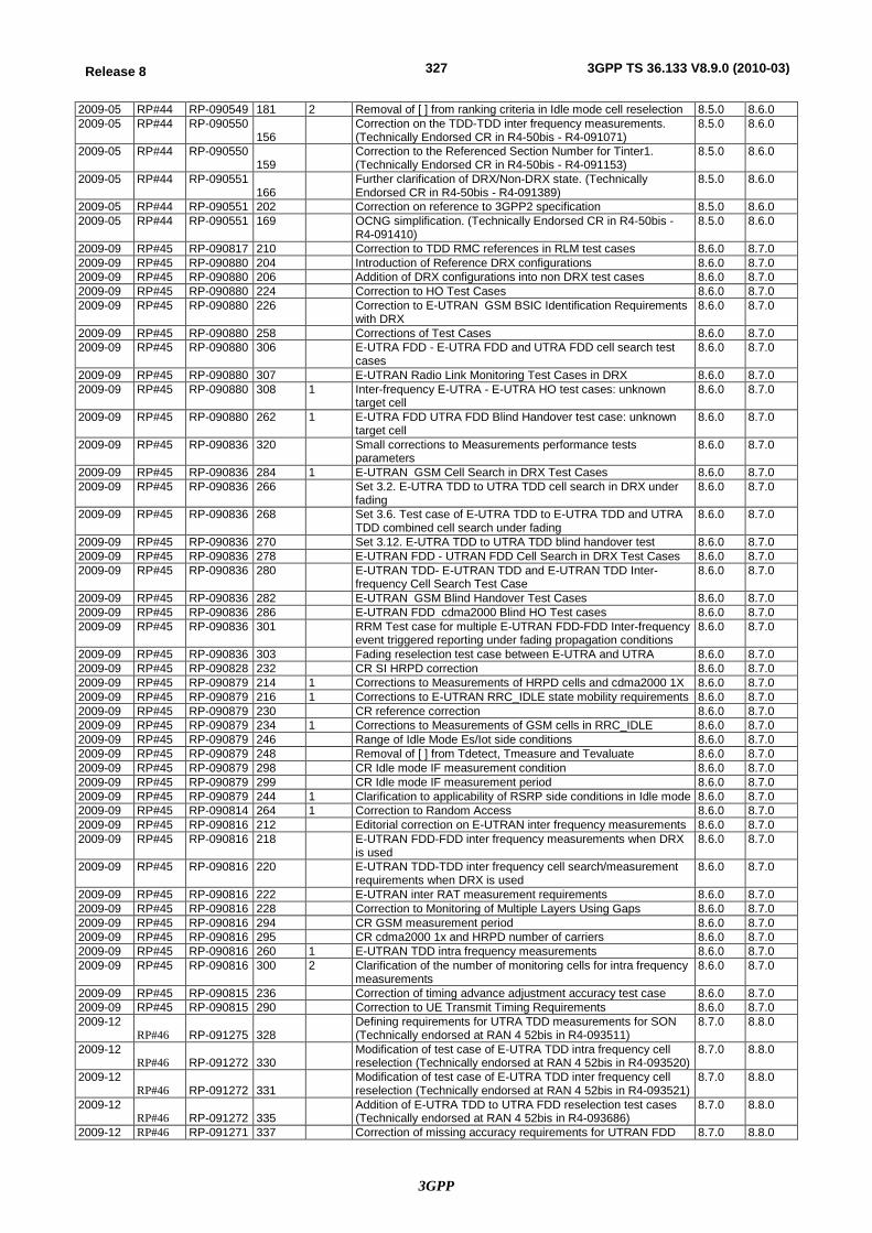
3GPP
327Release 8 3GPP TS 36.133 V8.9.0 (2010-03)
2009-05 RP#44 RP-090549 181 2 Removal of [ ] from ranking criteria in Idle mode cell reselection 8.5.0 8.6.0 2009-05 RP#44 RP-090550
156 Correction on the TDD-TDD inter frequency measurements.
(Technically Endorsed CR in R4-50bis - R4-091071) 8.5.0 8.6.0
2009-05 RP#44 RP-090550 159
Correction to the Referenced Section Number for Tinter1. (Technically Endorsed CR in R4-50bis - R4-091153)
8.5.0 8.6.0
2009-05 RP#44 RP-090551 166
Further clarification of DRX/Non-DRX state. (Technically Endorsed CR in R4-50bis - R4-091389)
8.5.0 8.6.0
2009-05 RP#44 RP-090551 202 Correction on reference to 3GPP2 specification 8.5.0 8.6.0 2009-05 RP#44 RP-090551 169 OCNG simplification. (Technically Endorsed CR in R4-50bis -
R4-091410) 8.5.0 8.6.0
2009-09 RP#45 RP-090817 210 Correction to TDD RMC references in RLM test cases 8.6.0 8.7.0 2009-09 RP#45 RP-090880 204 Introduction of Reference DRX configurations 8.6.0 8.7.0 2009-09 RP#45 RP-090880 206 Addition of DRX configurations into non DRX test cases 8.6.0 8.7.0 2009-09 RP#45 RP-090880 224 Correction to HO Test Cases 8.6.0 8.7.0 2009-09 RP#45 RP-090880 226 Correction to E-UTRAN GSM BSIC Identification Requirements
with DRX 8.6.0 8.7.0
2009-09 RP#45 RP-090880 258 Corrections of Test Cases 8.6.0 8.7.0 2009-09 RP#45 RP-090880 306 E-UTRA FDD - E-UTRA FDD and UTRA FDD cell search test
cases 8.6.0 8.7.0
2009-09 RP#45 RP-090880 307 E-UTRAN Radio Link Monitoring Test Cases in DRX 8.6.0 8.7.0 2009-09 RP#45 RP-090880 308 1 Inter-frequency E-UTRA - E-UTRA HO test cases: unknown
target cell 8.6.0 8.7.0
2009-09 RP#45 RP-090880 262 1 E-UTRA FDD UTRA FDD Blind Handover test case: unknown target cell
8.6.0 8.7.0
2009-09 RP#45 RP-090836 320 Small corrections to Measurements performance tests parameters
8.6.0 8.7.0
2009-09 RP#45 RP-090836 284 1 E-UTRAN GSM Cell Search in DRX Test Cases 8.6.0 8.7.0 2009-09 RP#45 RP-090836 266 Set 3.2. E-UTRA TDD to UTRA TDD cell search in DRX under
fading 8.6.0 8.7.0
2009-09 RP#45 RP-090836 268 Set 3.6. Test case of E-UTRA TDD to E-UTRA TDD and UTRA TDD combined cell search under fading
8.6.0 8.7.0
2009-09 RP#45 RP-090836 270 Set 3.12. E-UTRA TDD to UTRA TDD blind handover test 8.6.0 8.7.0 2009-09 RP#45 RP-090836 278 E-UTRAN FDD - UTRAN FDD Cell Search in DRX Test Cases 8.6.0 8.7.0 2009-09 RP#45 RP-090836 280 E-UTRAN TDD- E-UTRAN TDD and E-UTRAN TDD Inter-
frequency Cell Search Test Case 8.6.0 8.7.0
2009-09 RP#45 RP-090836 282 E-UTRAN GSM Blind Handover Test Cases 8.6.0 8.7.0 2009-09 RP#45 RP-090836 286 E-UTRAN FDD cdma2000 Blind HO Test cases 8.6.0 8.7.0 2009-09 RP#45 RP-090836 301 RRM Test case for multiple E-UTRAN FDD-FDD Inter-frequency
event triggered reporting under fading propagation conditions 8.6.0 8.7.0
2009-09 RP#45 RP-090836 303 Fading reselection test case between E-UTRA and UTRA 8.6.0 8.7.0 2009-09 RP#45 RP-090828 232 CR SI HRPD correction 8.6.0 8.7.0 2009-09 RP#45 RP-090879 214 1 Corrections to Measurements of HRPD cells and cdma2000 1X 8.6.0 8.7.0 2009-09 RP#45 RP-090879 216 1 Corrections to E-UTRAN RRC_IDLE state mobility requirements 8.6.0 8.7.0 2009-09 RP#45 RP-090879 230 CR reference correction 8.6.0 8.7.0 2009-09 RP#45 RP-090879 234 1 Corrections to Measurements of GSM cells in RRC_IDLE 8.6.0 8.7.0 2009-09 RP#45 RP-090879 246 Range of Idle Mode Es/Iot side conditions 8.6.0 8.7.0 2009-09 RP#45 RP-090879 248 Removal of [ ] from Tdetect, Tmeasure and Tevaluate 8.6.0 8.7.0 2009-09 RP#45 RP-090879 298 CR Idle mode IF measurement condition 8.6.0 8.7.0 2009-09 RP#45 RP-090879 299 CR Idle mode IF measurement period 8.6.0 8.7.0 2009-09 RP#45 RP-090879 244 1 Clarification to applicability of RSRP side conditions in Idle mode 8.6.0 8.7.0 2009-09 RP#45 RP-090814 264 1 Correction to Random Access 8.6.0 8.7.0 2009-09 RP#45 RP-090816 212 Editorial correction on E-UTRAN inter frequency measurements 8.6.0 8.7.0 2009-09 RP#45 RP-090816 218 E-UTRAN FDD-FDD inter frequency measurements when DRX
is used 8.6.0 8.7.0
2009-09 RP#45 RP-090816 220 E-UTRAN TDD-TDD inter frequency cell search/measurement requirements when DRX is used
8.6.0 8.7.0
2009-09 RP#45 RP-090816 222 E-UTRAN inter RAT measurement requirements 8.6.0 8.7.0 2009-09 RP#45 RP-090816 228 Correction to Monitoring of Multiple Layers Using Gaps 8.6.0 8.7.0 2009-09 RP#45 RP-090816 294 CR GSM measurement period 8.6.0 8.7.0 2009-09 RP#45 RP-090816 295 CR cdma2000 1x and HRPD number of carriers 8.6.0 8.7.0 2009-09 RP#45 RP-090816 260 1 E-UTRAN TDD intra frequency measurements 8.6.0 8.7.0 2009-09 RP#45 RP-090816 300 2 Clarification of the number of monitoring cells for intra frequency
measurements 8.6.0 8.7.0
2009-09 RP#45 RP-090815 236 Correction of timing advance adjustment accuracy test case 8.6.0 8.7.0 2009-09 RP#45 RP-090815 290 Correction to UE Transmit Timing Requirements 8.6.0 8.7.0 2009-12
RP#46 RP-091275 328 Defining requirements for UTRA TDD measurements for SON (Technically endorsed at RAN 4 52bis in R4-093511)
8.7.0 8.8.0
2009-12 RP#46 RP-091272 330
Modification of test case of E-UTRA TDD intra frequency cell reselection (Technically endorsed at RAN 4 52bis in R4-093520)
8.7.0 8.8.0
2009-12 RP#46 RP-091272 331
Modification of test case of E-UTRA TDD inter frequency cell reselection (Technically endorsed at RAN 4 52bis in R4-093521)
8.7.0 8.8.0
2009-12 RP#46 RP-091272 335
Addition of E-UTRA TDD to UTRA FDD reselection test cases (Technically endorsed at RAN 4 52bis in R4-093686)
8.7.0 8.8.0
2009-12 RP#46 RP-091271 337 Correction of missing accuracy requirements for UTRAN FDD 8.7.0 8.8.0
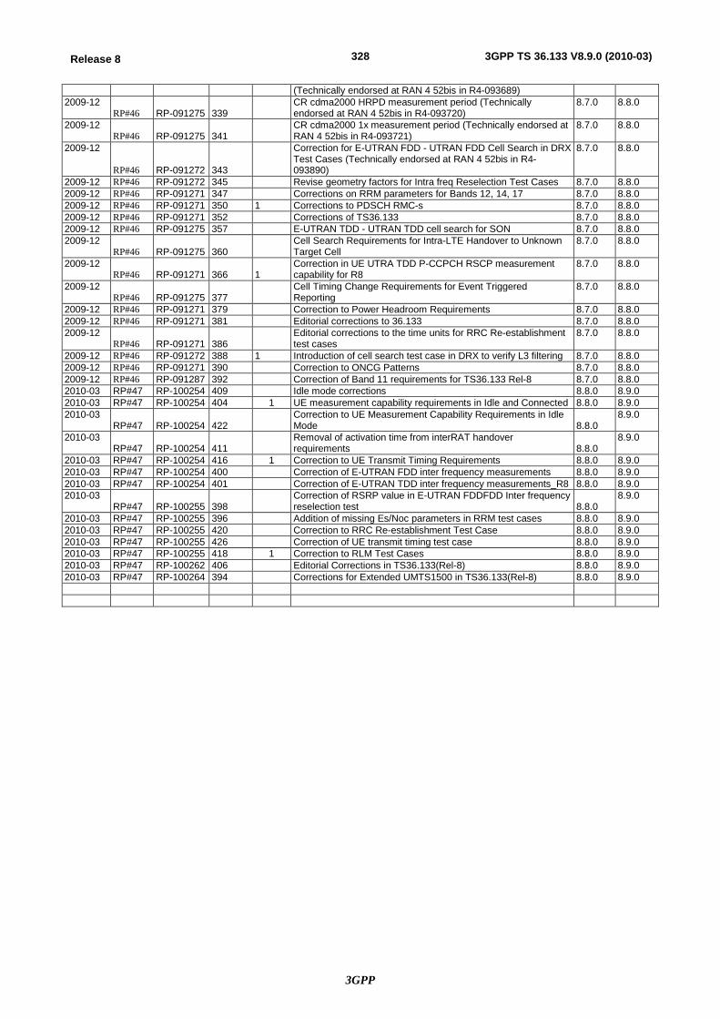
3GPP
328Release 8 3GPP TS 36.133 V8.9.0 (2010-03)
(Technically endorsed at RAN 4 52bis in R4-093689) 2009-12
RP#46 RP-091275 339 CR cdma2000 HRPD measurement period (Technically endorsed at RAN 4 52bis in R4-093720)
8.7.0 8.8.0
2009-12 RP#46 RP-091275 341
CR cdma2000 1x measurement period (Technically endorsed at RAN 4 52bis in R4-093721)
8.7.0 8.8.0
2009-12
RP#46 RP-091272 343
Correction for E-UTRAN FDD - UTRAN FDD Cell Search in DRX Test Cases (Technically endorsed at RAN 4 52bis in R4-093890)
8.7.0 8.8.0
2009-12 RP#46 RP-091272 345 Revise geometry factors for Intra freq Reselection Test Cases 8.7.0 8.8.0 2009-12 RP#46 RP-091271 347 Corrections on RRM parameters for Bands 12, 14, 17 8.7.0 8.8.0 2009-12 RP#46 RP-091271 350 1 Corrections to PDSCH RMC-s 8.7.0 8.8.0 2009-12 RP#46 RP-091271 352 Corrections of TS36.133 8.7.0 8.8.0 2009-12 RP#46 RP-091275 357 E-UTRAN TDD - UTRAN TDD cell search for SON 8.7.0 8.8.0 2009-12
RP#46 RP-091275 360 Cell Search Requirements for Intra-LTE Handover to Unknown Target Cell
8.7.0 8.8.0
2009-12 RP#46 RP-091271 366 1
Correction in UE UTRA TDD P-CCPCH RSCP measurement capability for R8
8.7.0 8.8.0
2009-12 RP#46 RP-091275 377
Cell Timing Change Requirements for Event Triggered Reporting
8.7.0 8.8.0
2009-12 RP#46 RP-091271 379 Correction to Power Headroom Requirements 8.7.0 8.8.0 2009-12 RP#46 RP-091271 381 Editorial corrections to 36.133 8.7.0 8.8.0 2009-12
RP#46 RP-091271 386 Editorial corrections to the time units for RRC Re-establishment test cases
8.7.0 8.8.0
2009-12 RP#46 RP-091272 388 1 Introduction of cell search test case in DRX to verify L3 filtering 8.7.0 8.8.0 2009-12 RP#46 RP-091271 390 Correction to ONCG Patterns 8.7.0 8.8.0 2009-12 RP#46 RP-091287 392 Correction of Band 11 requirements for TS36.133 Rel-8 8.7.0 8.8.0 2010-03 RP#47 RP-100254 409 Idle mode corrections 8.8.0 8.9.0 2010-03 RP#47 RP-100254 404 1 UE measurement capability requirements in Idle and Connected 8.8.0 8.9.0 2010-03
RP#47 RP-100254 422 Correction to UE Measurement Capability Requirements in Idle Mode 8.8.0
8.9.0
2010-03 RP#47 RP-100254 411
Removal of activation time from interRAT handover requirements 8.8.0
8.9.0
2010-03 RP#47 RP-100254 416 1 Correction to UE Transmit Timing Requirements 8.8.0 8.9.0 2010-03 RP#47 RP-100254 400 Correction of E-UTRAN FDD inter frequency measurements 8.8.0 8.9.0 2010-03 RP#47 RP-100254 401 Correction of E-UTRAN TDD inter frequency measurements_R8 8.8.0 8.9.0 2010-03
RP#47 RP-100255 398 Correction of RSRP value in E-UTRAN FDDFDD Inter frequency reselection test 8.8.0
8.9.0
2010-03 RP#47 RP-100255 396 Addition of missing Es/Noc parameters in RRM test cases 8.8.0 8.9.0 2010-03 RP#47 RP-100255 420 Correction to RRC Re-establishment Test Case 8.8.0 8.9.0 2010-03 RP#47 RP-100255 426 Correction of UE transmit timing test case 8.8.0 8.9.0 2010-03 RP#47 RP-100255 418 1 Correction to RLM Test Cases 8.8.0 8.9.0 2010-03 RP#47 RP-100262 406 Editorial Corrections in TS36.133(Rel-8) 8.8.0 8.9.0 2010-03 RP#47 RP-100264 394 Corrections for Extended UMTS1500 in TS36.133(Rel-8) 8.8.0 8.9.0