
12_v5_gpsfordesigner_ws_12_030402
24
WS12-1 WORKSHOP 12 FLAT PLATE COLUMN BUCKLING CAT509, Workshop 12, March 2002
description
Work 12
Transcript of 12_v5_gpsfordesigner_ws_12_030402

WS12-1
WORKSHOP 12
FLAT PLATE COLUMN BUCKLING
CAT509, Workshop 12, March 2002

WS12-2CAT509, Workshop 12, March 2002
WS12-3CAT509, Workshop 12, March 2002
Fre
e
Fre
e
Simplysupported
Simplysupported
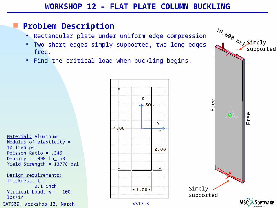
WORKSHOP 12 – FLAT PLATE COLUMN BUCKLING
Material: AluminumModulus of elasticity = 10.15e6 psiPoisson Ratio = .346Density = .098 lb_in3Yield Strength = 13778 psi
Design requirements:Thickness, t = 0.1 inchVertical Load, w = 100 lbs/in
Problem Description Rectangular plate under uniform edge compression Two short edges simply supported, two long edges free. Find the critical load when buckling begins.
10,000 psi

WS12-4CAT509, Workshop 12, March 2002
WORKSHOP 12 – FLAT PLATE COLUMN BUCKLING
Hand calculations
Critical load of a long slender column:
Verify model by checking deflection using the standard formula for a simply supported beam at both ends with uniform load over the entire span using a pressure of 100 psi (3D).
100 lbs/in (2D)
4.0 inch

WS12-5CAT509, Workshop 12, March 2002
Suggested Exercise Steps
1. Create a new CATIA analysis document (.CATAnalysis).2. Mesh globally with parabolic elements.3. Create virtual parts and apply advanced restraints (simply
supported).4. Apply a force. 5. Insert a Buckling Case.6. Setup static and buckling parameters.7. Compute all (the static and buckling analysis).8. Check global and local precision (animate deformation, adaptive
boxes and extremas).9. Visualize final results.10. Save the analysis document.
WORKSHOP 12 – FLAT PLATE COLUMN BUCKLING

WS12-6CAT509, Workshop 12, March 2002
Step 1. Create a new CATIA analysis document
Steps:
1. Open the existing ws12columnPlateBuck .CATPart from the training directory.
2. Apply aluminum material properties to the part as required.
3. Launch the Generative Structural Analysis workbench for a Static Analysis case.
4. Specify the Computations and Results storage locations as shown.
4
2
1
3

WS12-7CAT509, Workshop 12, March 2002
Step 2. Mesh globally with parabolic elements
Steps:
1. Globally mesh as shown
Thin gauge sheet problems are very sensitive to the mesh parameters. Parabolic elements are highly recommended for this because they are formulated with a parabolic displacement field within the element, which agrees with basic bending theory.
1

WS12-8CAT509, Workshop 12, March 2002
Step 3. Create virtual parts
1
2Steps:
1. Select the Rigid Virtual Part icon, select the upper face, select OK.
2. Repeat the process to create a second rigid virtual part on the bottom face.

WS12-9CAT509, Workshop 12, March 2002
Step 3. Apply advanced restraints
1
2
Steps:
1. Select the Advanced Restraint icon, select virtual part 1 at the top of the plate
2. Select Restrain Translation 1, select OK.

WS12-10CAT509, Workshop 12, March 2002
Step 3. Apply advanced restraints
1
2
Steps:
1. Select the Advanced Restraint icon again, select virtual part 2 at the bottom of the plate
2. Restrain all directions except Rotation 2, select OK.

WS12-11CAT509, Workshop 12, March 2002
Step 4. Apply a force
1
Apply force to the top face
Steps:
1. Select the Surface Force Density icon and select the top face.
2. Enter -10000 in the z direction and select OK.
2

WS12-12CAT509, Workshop 12, March 2002
Step 5. Insert a Buckling Case
Steps:
1. Rename the Static Case Solution.1 to ColumnPlateSolution.
2. From the menu select Insert then Buckling Case.
3. Select ColumnPlateSolution from the features tree as your reference solution.
For clarity and organization it’s a good idea to start uniquely identifying cases.
1
2
3

WS12-13CAT509, Workshop 12, March 2002
Step 6. Setup static and buckling parameters
Steps:
1. Double click ColumnPlateSolution in the features tree to verify parameters. Click OK.
2. Double click Buckling Case Solution in the features tree to verify parameters. Click OK.
You should be aware of what calculation methods will be used.
1
2

WS12-14CAT509, Workshop 12, March 2002
Step 7. Compute all
1
Save first.
Steps:
1. Compute all objects.
WS12-15CAT509, Workshop 12, March 2002
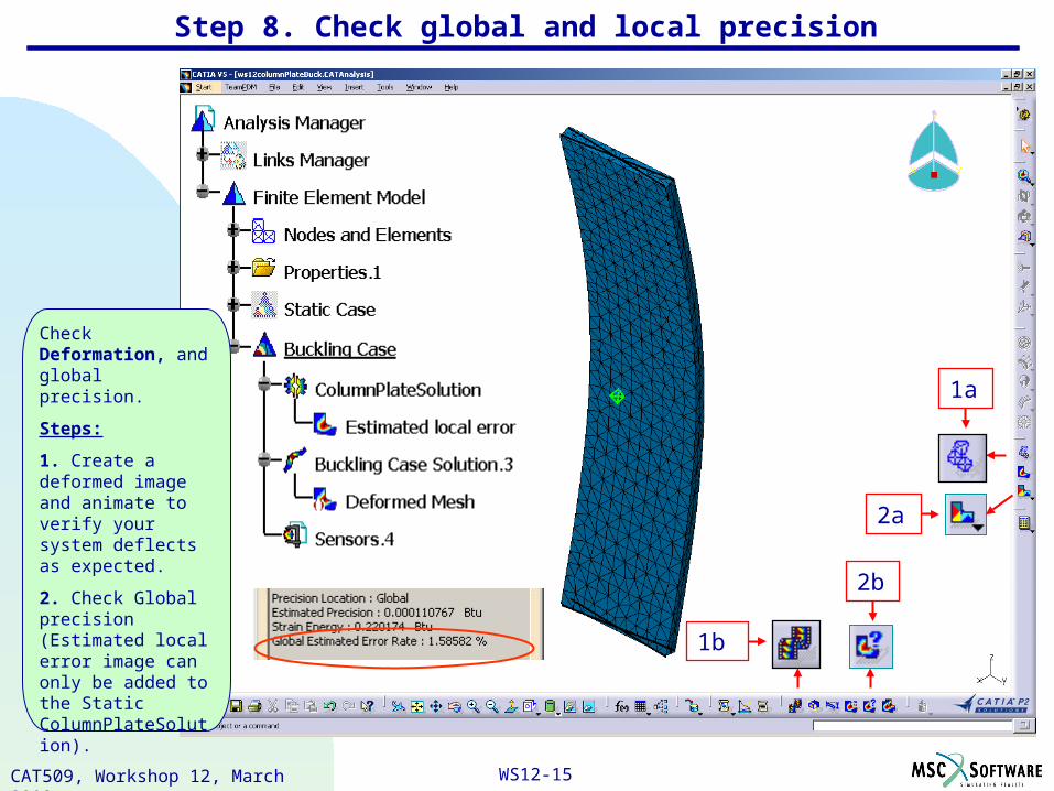
Check Deformation, and global precision.
Steps:
1. Create a deformed image and animate to verify your system deflects as expected.
2. Check Global precision (Estimated local error image can only be added to the Static ColumnPlateSolution).
Step 8. Check global and local precision
1a
1b
2a
2b

WS12-16CAT509, Workshop 12, March 2002
Step 8. Check global and local precision
Find the global element with the highest estimated error.
Find local precision.
Steps:
1. Use the Search Image Extrema icon.
2. Local precision is found using the adaptivity box icon.
Local error shows energy balanced in the plate center, our area of most concern. We have a precise model.
2
1

WS12-17CAT509, Workshop 12, March 2002
Step 9. Visualize final results
Find the critical load when this plate will fail.
Steps
1. Make sure the Buckling Case is “Set As Current Case”.
2. Right click Sensors in the features tree then select Create Sensor.
3. Click to highlight bucklingfactors in the Sensor Creation window. Click OK.
4. Double click this sensor “Buckling Factors” in the features tree.
1
2
4
Critical Load = (.519)(10,000 psi) = 5190 psi
Compare with hand calculations:Critical Load = (5190 psi)(0.1 inch2) = 519 lbs.Hand calculations = 522 lbs.
3

WS12-18CAT509, Workshop 12, March 2002
Step 9. Visualize final results
Add a different Static Case: Beam simply supported at both ends, uniform load over entire area.
Steps
1. From the menu select Insert then Static Case.
2. Select existing restraints to save setup time.
3. Rename Simply Supported Beam.
We are doing this to verify that the beam is deflecting properly.
Also introducing multiple load cases.
1
2
3

WS12-19CAT509, Workshop 12, March 2002
Step 9. Visualize final results
Load 100 psi and compute.
Steps
1. Use the surface force density icon.
2. Select the face as shown.
3. Compute all.
1
3
2

WS12-20CAT509, Workshop 12, March 2002
Step 9. Visualize final results
Compare hand calculation displacements.
Steps
1. Select the Displacement icon.
Hand calc’s = .394 in.
FEA = .398 in.
Looks good.
1

WS12-21CAT509, Workshop 12, March 2002
Step 9. Visualize final results
Hand Calculations .1 inch Parabolic Global Mesh, .01 inch sag
Global % Precision error
Local % Precision error
NA
NA
1.58 %
0 %
Error Estimate NA 1.44e-9 Btu global
Critical Load 522 lbs 519 lbs
Model verification using simply supported beam displacement
0.394 inch 0.398 inch
Conclusions CATIA V5 GSA workbench is validated for a flat plate
column buckling scenario.

WS12-22CAT509, Workshop 12, March 2002
Step 10. Save the analysis document
Save your documents

WS12-23CAT509, Workshop 12, March 2002
WORKSHOP 12…
FLAT PLATE BUCKLING,PINNED ALL FOUR EDGESFIXED ALL FOUR EDGES
PINNED TWO EDGES, FIXED TWO EDGES
CANTILEVER PLATE LATERAL BUCKLING
CAT509, Workshop 12, March 2002

WS12-24CAT509, Workshop 12, March 2002


