指導教授 : 王明賢
40
Study on maximum torque generation for sensorless controlled brushless DC motor with trapezoidal back EMF 指指指指:指指指 指 指:指指指 指指指指指指指
description
Study on maximum torque generation for sensorless controlled brushless DC motor with trapezoidal back EMF. 指導教授 : 王明賢. 學 生 : 楊政達 . 南台科大電機系 . OUTLINE. Abstract Introduction Generation torque analysis of brushless DC motor - PowerPoint PPT Presentation
Transcript of 指導教授 : 王明賢
Study on maximum torque generation for sensorless controlled brushless DC motor with trapezoidal back EMF
指導教授:王明賢學 生:楊政達
南台科大電機系
2
OUTLINE Abstract Introduction Generation torque analysis of brushless DC
motor Controller for maximum torque generation Simulation and experimental results Conclusion
Abstract The sensorless controlled brushless DC motor with trapezoidal back
EMF has been studied. Since the detected position information on the sensorless rotor has some uncertainty, the brushless DC motor cannot be driven with a maximum torque.
To investigate the nature of torque in the sensorless controlled brushless DC motor, the torque characteristics as a function of commutation delay (or commutation timing error) have been analysed. It shows that the generation torque is influenced by the commutation delay and has a single maximum point. This maximum point is changed by the rotating speed and load conditions.
An iterative learning algorithm and a fuzzy logic controller are employed to drive the brushless DC motor with maximum torque.
3
Introduction
Permanent magnet brushless DC motors are appealing candidates for many high performance applications because of their attractive characteristics in such key categories as power density, torque-to-inertia ratio, power efficiency, robustness and reliability
The motor drive system requires a rotor position sensor to provide the proper commutation sequence. The position sensors such as resolvers, absolute position encorders and Hall sensors increase the cost and size of the motor.
The position detection algorithm using back EMF is a practical method for a position sensorless controlled brushless DC motor.
4
Introduction The rotor position detection errors can be divided into the error
deviation and group delay (average error). The error deviation increases the torque pulsation since it causes commutation imbalances. The group delay influences the average torque because it makes the commutation delay.
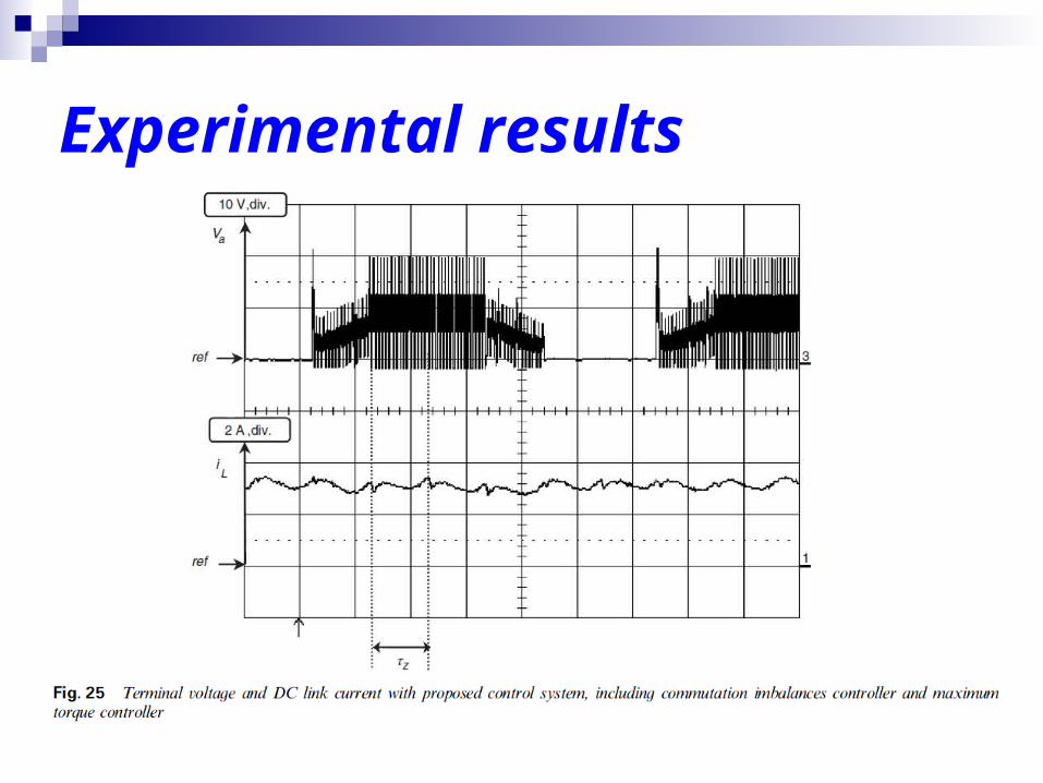
The results show that the commutation imbalances can be regulated and the firing angle is well adjusted to the position of the maximum torque in any case. It is well demonstrated from these results that the proposed control scheme provides the desirable performance of a sensorless controlled brushless DC motor.
5
Generation torque analysis of brushless DC motor
The generation torque and the phase currents in a brushless DC motor with trapezoidal back EMF are strongly influenced by the rotor position detection error since it cannot commutate the phase current at an optimal point.
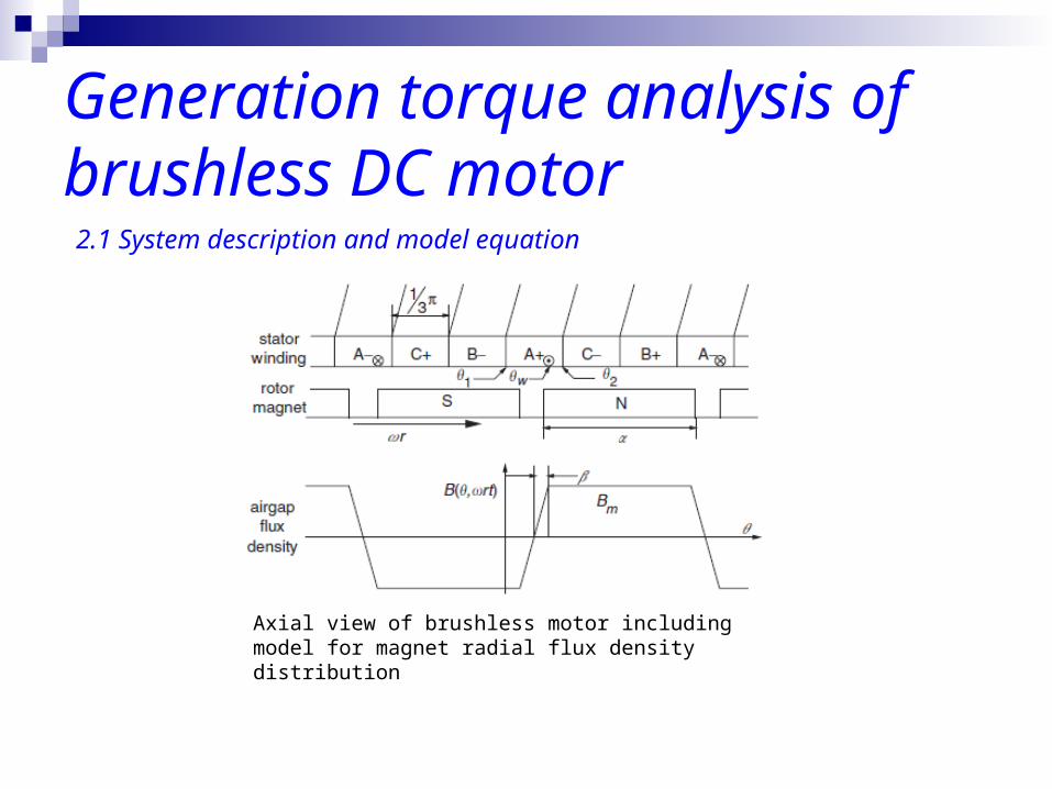
As illustrated in this Figure, it is assumed that three stator phases
occupy consecutive nonoverlapping 60° (elec.) phase belts along the stator airgap surface.
6
2.1 System description and model equation
Generation torque analysis of brushless DC motor2.1 System description and model equation
Axial view of brushless motor including model for magnet radial flux density distribution
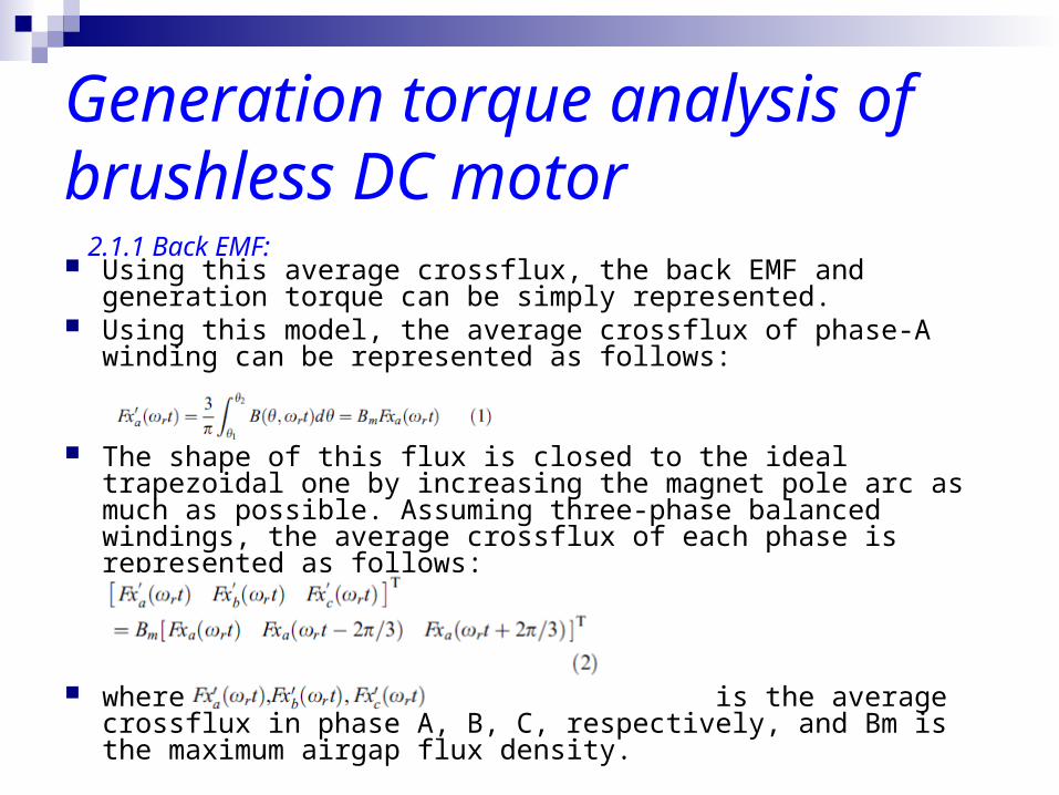
Using this average crossflux, the back EMF and generation torque can be simply represented.
Using this model, the average crossflux of phase-A winding can be represented as follows:
The shape of this flux is closed to the ideal trapezoidal one by increasing the magnet pole arc as much as possible. Assuming three-phase balanced windings, the average crossflux of each phase is represented as follows:
where is the average crossflux in phase A, B, C, respectively, and Bm is the maximum airgap flux density.
Generation torque analysis of brushless DC motor
2.1.1 Back EMF:
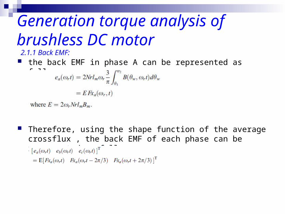
Generation torque analysis of brushless DC motor the back EMF in phase A can be represented as follows:
Therefore, using the shape function of the average crossflux , the back EMF of each phase can be represented as follows:
2.1.1 Back EMF:
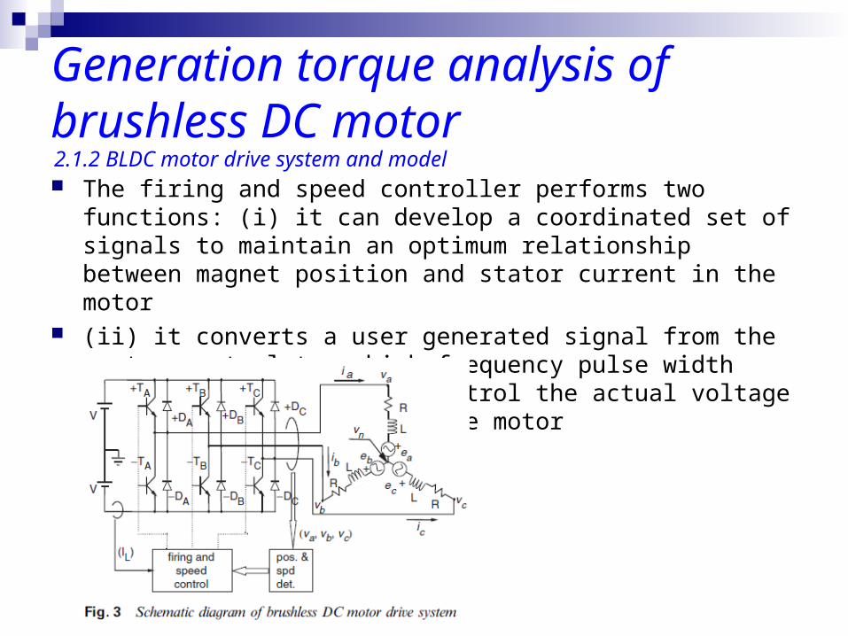
Generation torque analysis of brushless DC motor The firing and speed controller performs two functions: (i) it can
develop a coordinated set of signals to maintain an optimum relationship between magnet position and stator current in the motor
(ii) it converts a user generated signal from the system control to a high frequency pulse width modulation (PWM) one to control the actual voltage and current delivered to the motor
2.1.2 BLDC motor drive system and model
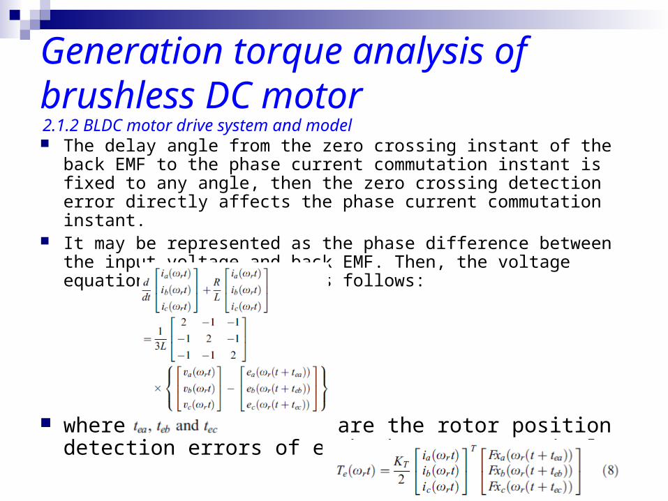
Generation torque analysis of brushless DC motor The delay angle from the zero crossing instant of the back EMF to
the phase current commutation instant is fixed to any angle, then the zero crossing detection error directly affects the phase current commutation instant.
It may be represented as the phase difference between the input voltage and back EMF. Then, the voltage equation can be written as follows:
where are the rotor position detection errors of each phase, respectively.
2.1.2 BLDC motor drive system and model
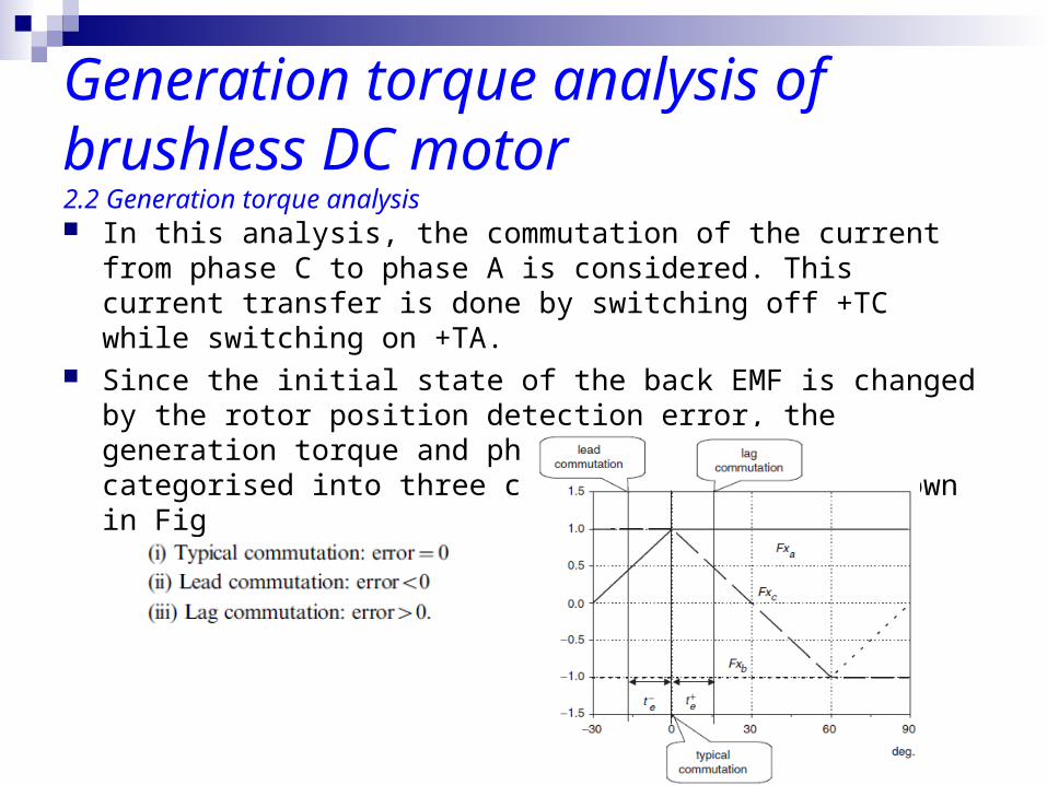
Generation torque analysis of brushless DC motor In this analysis, the commutation of the current from phase C to
phase A is considered. This current transfer is done by switching off +TC while switching on +TA.
Since the initial state of the back EMF is changed by the rotor position detection error, the generation torque and phase current are categorised into three commutation modes as shown in Fig
2.2 Generation torque analysis
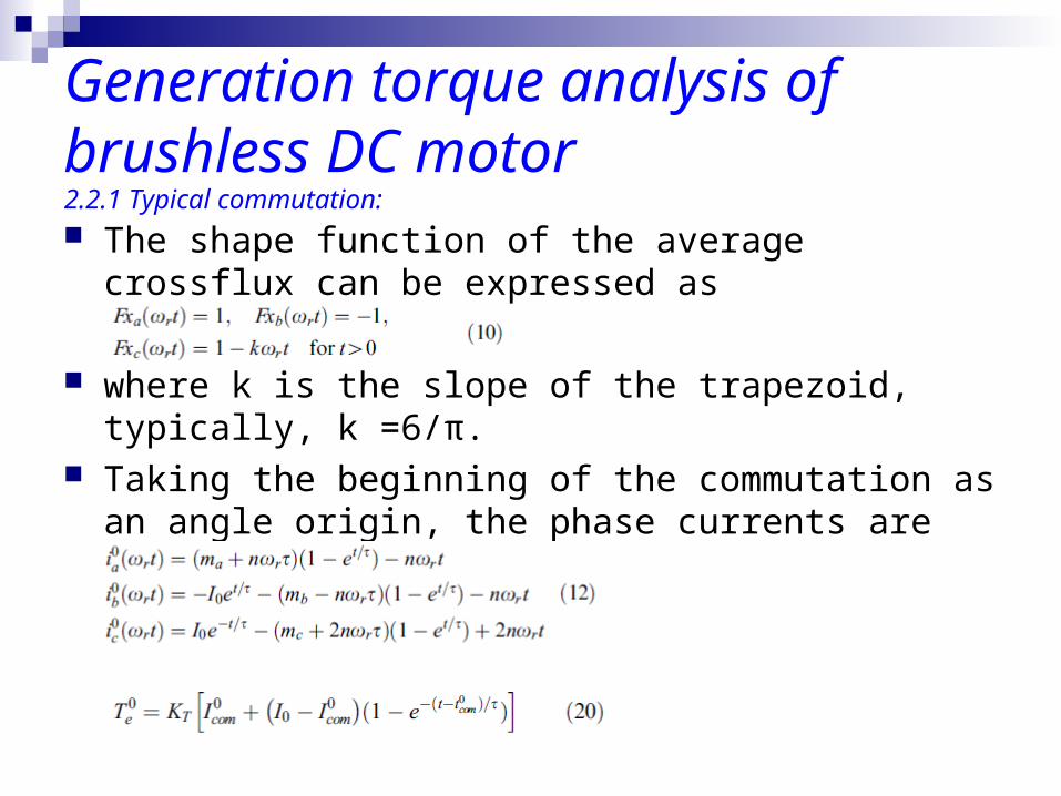
Generation torque analysis of brushless DC motor The shape function of the average crossflux can be
expressed as
where k is the slope of the trapezoid, typically, k =6/π. Taking the beginning of the commutation as an angle
origin, the phase currents are represented as follows
2.2.1 Typical commutation:
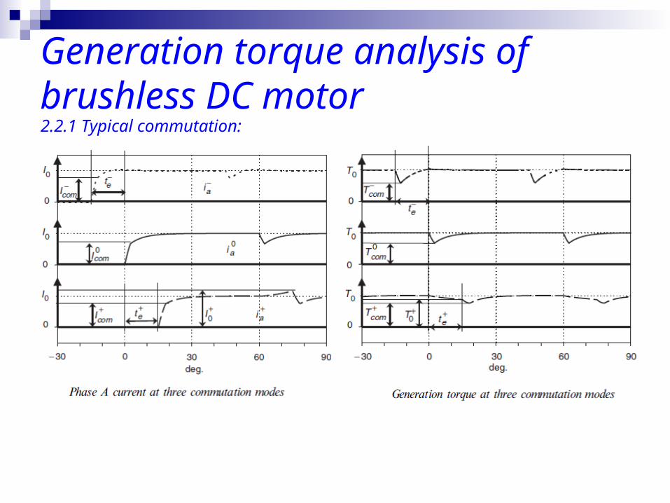
Generation torque analysis of brushless DC motor2.2.1 Typical commutation:
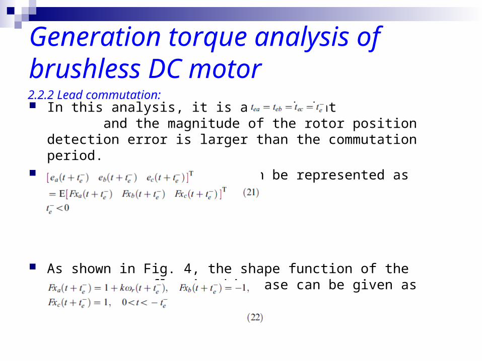
Generation torque analysis of brushless DC motor In this analysis, it is assumed that and the magnitude
of the rotor position detection error is larger than the commutation period.
Therefore, the back EMF can be represented as follows:
As shown in Fig. 4, the shape function of the average crossflux in this case can be given as
2.2.2 Lead commutation:
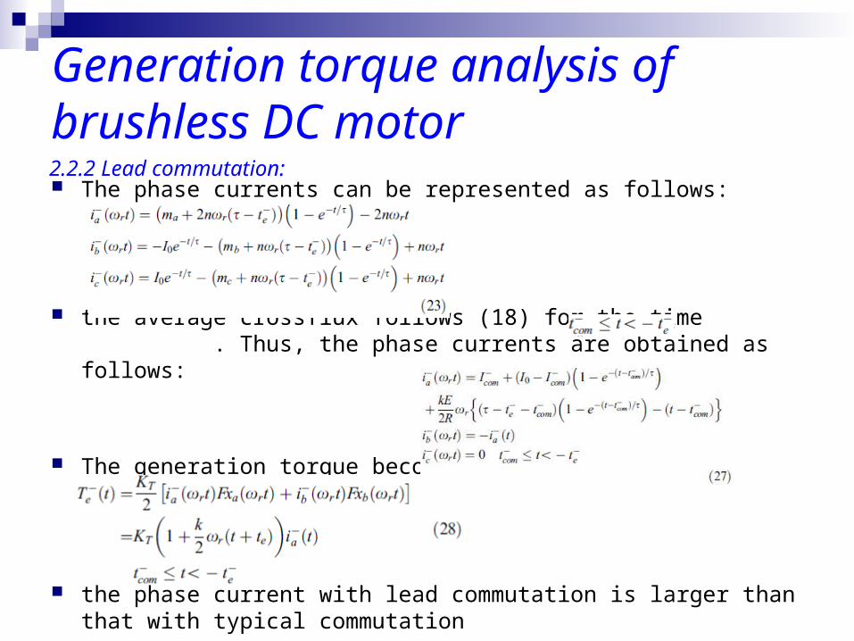
Generation torque analysis of brushless DC motor The phase currents can be represented as follows:
the average crossflux follows (18) for the time . Thus, the phase currents are obtained as follows:
The generation torque becomes
the phase current with lead commutation is larger than that with typical commutation
2.2.2 Lead commutation:
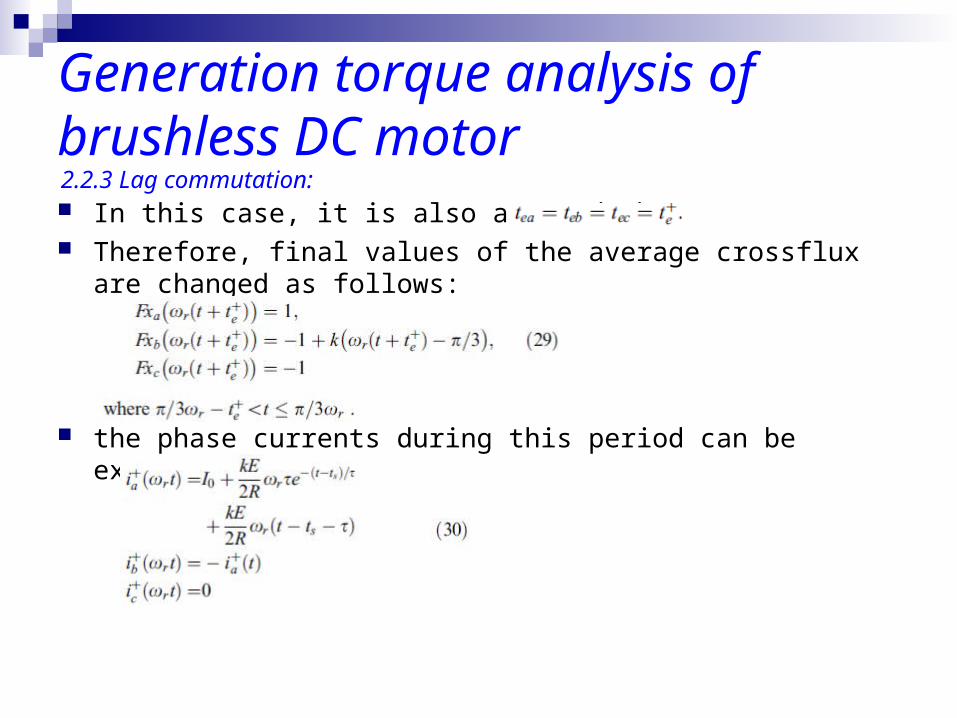
Generation torque analysis of brushless DC motor In this case, it is also assumed that Therefore, final values of the average crossflux are changed as
follows:
the phase currents during this period can be expressed as follows:
2.2.3 Lag commutation:
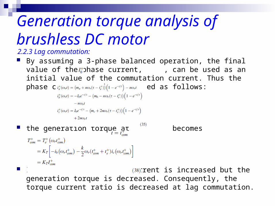
Generation torque analysis of brushless DC motor By assuming a 3-phase balanced operation, the final value of the
phase current, , can be used as an initial value of the commutation current. Thus the phase current can be expressed as follows:
the generation torque at becomes
It shows that the phase current is increased but the generation torque is decreased. Consequently, the torque current ratio is decreased at lag commutation.
2.2.3 Lag commutation:
Generation torque analysis of brushless DC motor The torque–current ratio is changed with a rotor position detection
error in a brushless DC motor.
In this analysis, the torque–current ratio as a function of the delay timing will be analysed to find out a maximum torque operating condition.
The detailed torque–current ratio calculation for a brushless DC motor requires current equations and torque equations including the effects of motor parameter.
2.3 Torque–current ratio
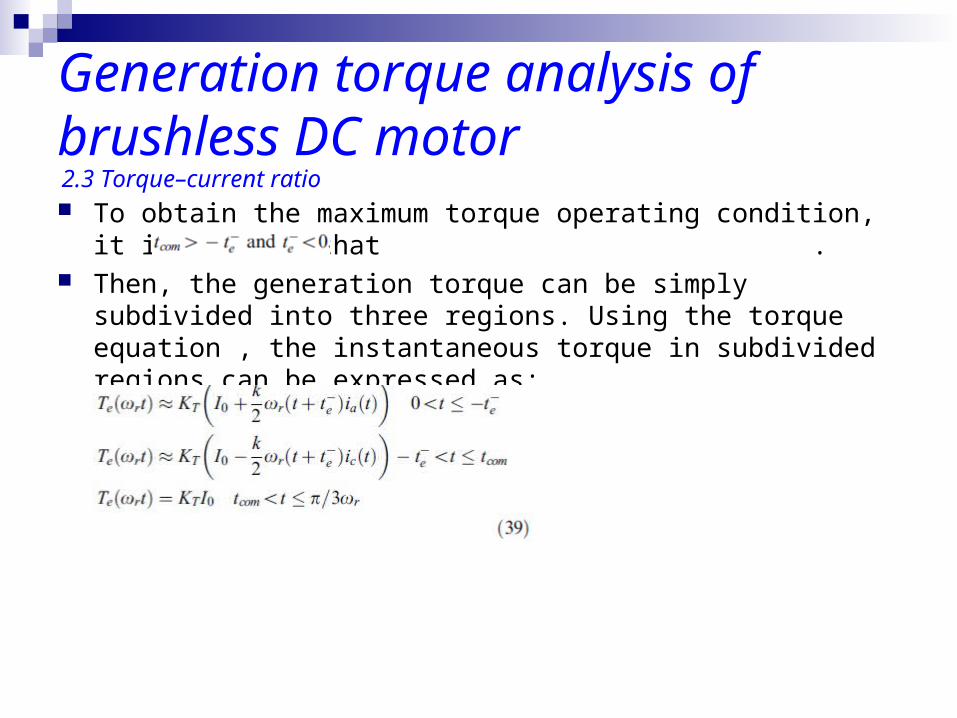
Generation torque analysis of brushless DC motor To obtain the maximum torque operating condition, it is assumed
that . Then, the generation torque can be simply subdivided into three
regions. Using the torque equation , the instantaneous torque in subdivided regions can be expressed as:
2.3 Torque–current ratio
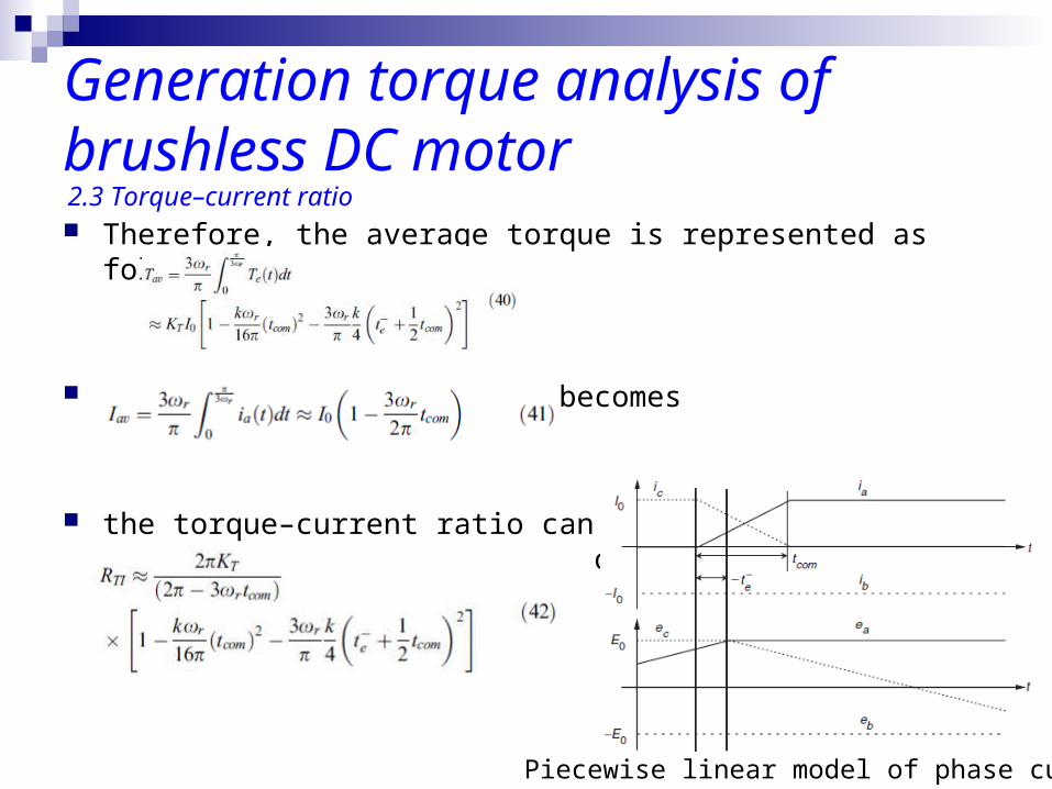
Generation torque analysis of brushless DC motor Therefore, the average torque is represented as follows:
The average input current becomes
the torque–current ratio can be obtained as follows:
2.3 Torque–current ratio
Piecewise linear model of phase current
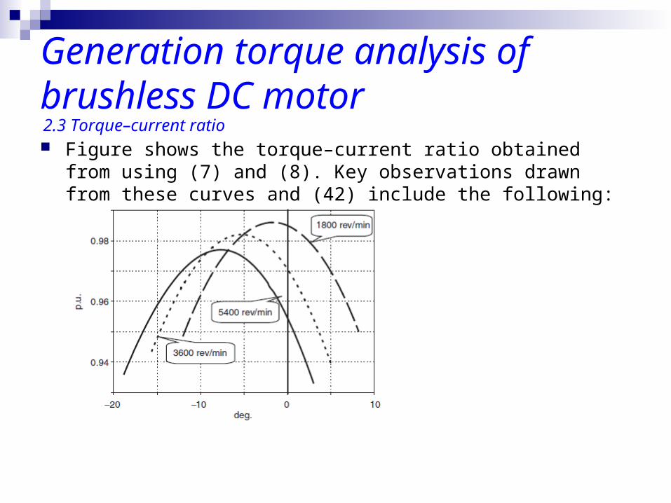
Generation torque analysis of brushless DC motor Figure shows the torque–current ratio obtained from using (7) and
(8). Key observations drawn from these curves and (42) include the following:
2.3 Torque–current ratio
Generation torque analysis of brushless DC motor Increasing the rotor position detection error has the effect of
reducing the average torque.
The average torque will be maximised by lead commutation with about half the phase current commutation time
The delay time for the maximum torque can be defined uniquely. Thus, the delay time can be controlled to maximise the generation torque.
The delay time for the maximum torque should be controlled to increase the efficiency of a total drive system.
2.3 Torque–current ratio
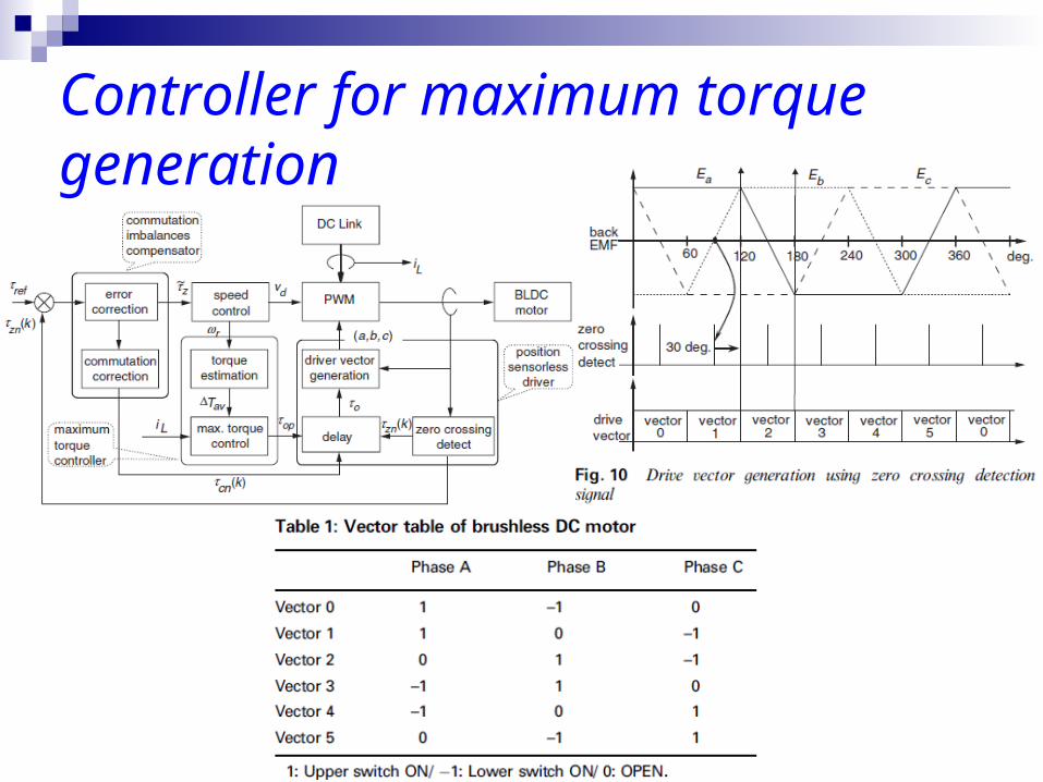
Controller for maximum torque generation The position sensorless driver contains rotor position detection,
drive vector generation and delay block.
The rotor position is estimated from the zero crossing point of back EMF.
The drive vector is generated by the zero crossing detection signal, and this generation scheme is shown in Fig. 10.
The drive vector can be summarised as shown in Table 1.
Controller for maximum torque generation
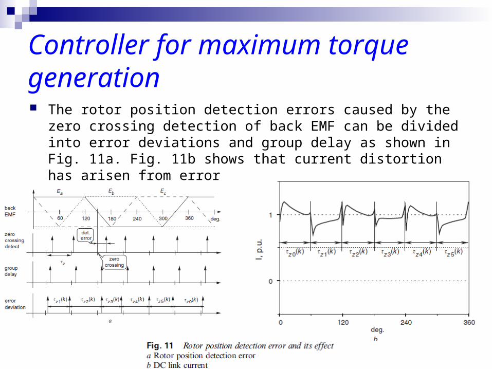
Controller for maximum torque generation The rotor position detection errors caused by the zero crossing
detection of back EMF can be divided into error deviations and group delay as shown in Fig. 11a. Fig. 11b shows that current distortion has arisen from error
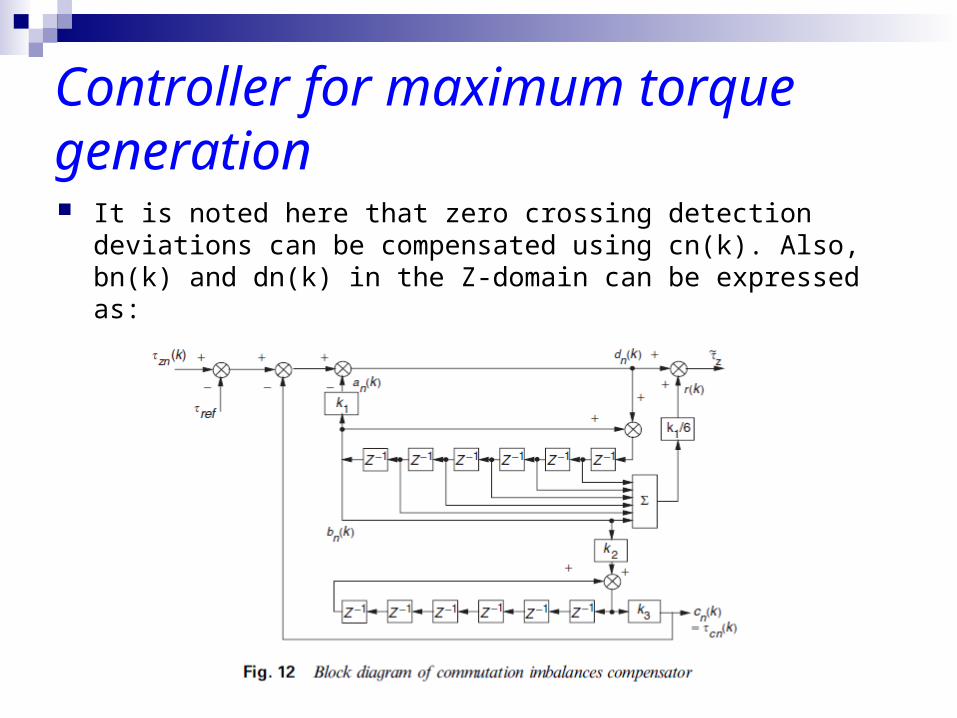
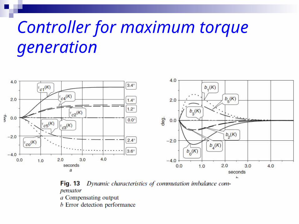
Controller for maximum torque generation It is noted here that zero crossing detection deviations can be
compensated using cn(k). Also, bn(k) and dn(k) in the Z-domain can be expressed as:
Controller for maximum torque generation
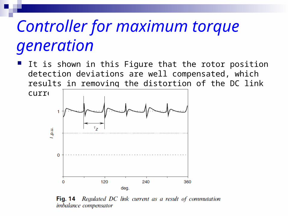
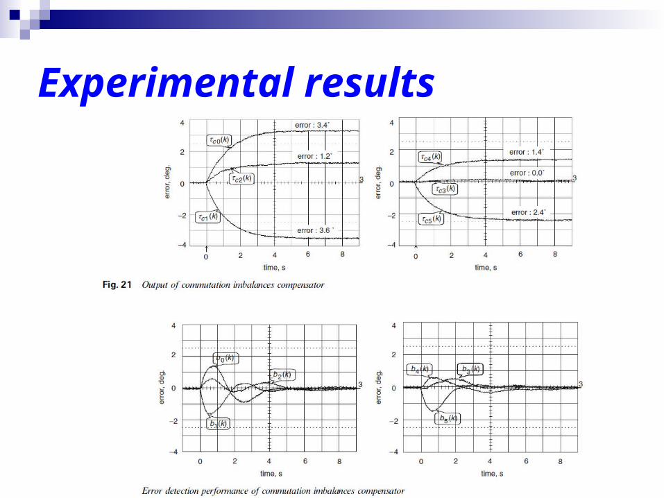
Controller for maximum torque generation It is shown in this Figure that the rotor position detection deviations
are well compensated, which results in removing the distortion of the DC link current as shown in Fig. 14.
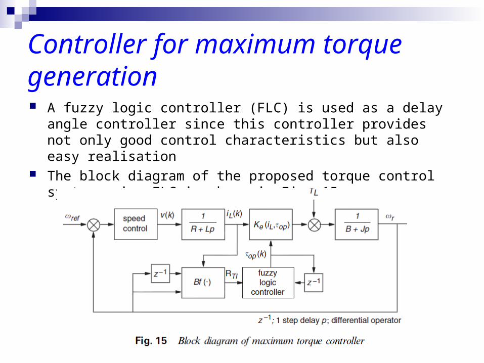
Controller for maximum torque generation A fuzzy logic controller (FLC) is used as a delay angle controller
since this controller provides not only good control characteristics but also easy realisation
The block diagram of the proposed torque control system using FLC is shown in Fig. 15.
Controller for maximum torque generation The FLC is basically composed of four principle components.
These are the fuzzification interface, knowledge base, inference engine and defuzzification interface.
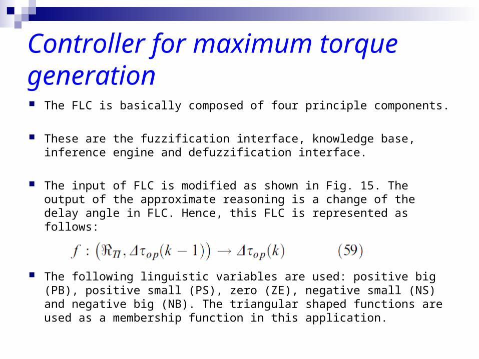
The input of FLC is modified as shown in Fig. 15. The output of the approximate reasoning is a change of the delay angle in FLC. Hence, this FLC is represented as follows:
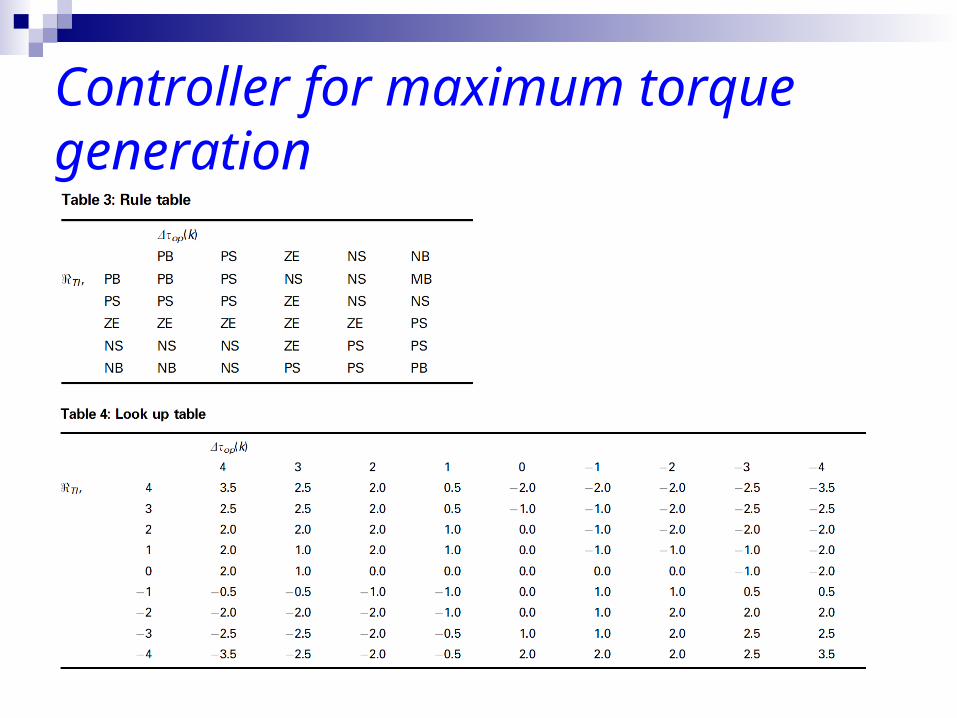
The following linguistic variables are used: positive big (PB), positive small (PS), zero (ZE), negative small (NS) and negative big (NB). The triangular shaped functions are used as a membership function in this application.
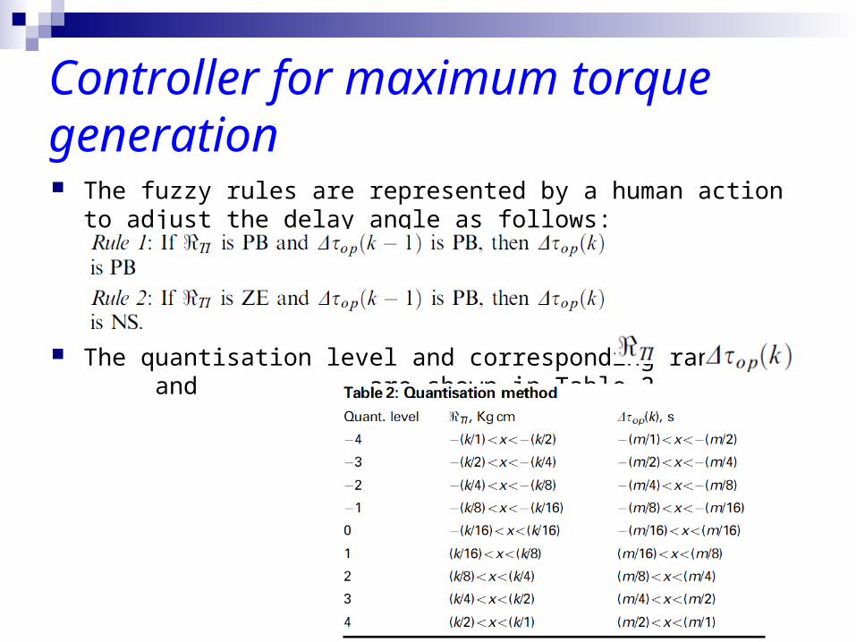
Controller for maximum torque generation The fuzzy rules are represented by a human action to adjust the
delay angle as follows:
The quantisation level and corresponding range of and are shown in Table 2,
Controller for maximum torque generation
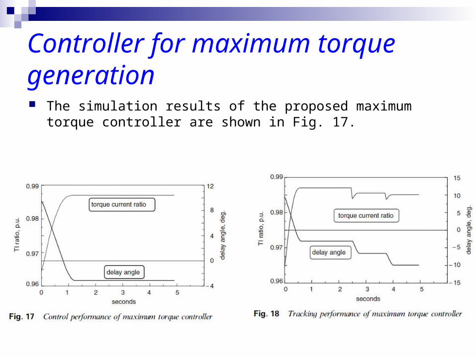
Controller for maximum torque generation The simulation results of the proposed maximum torque controller
are shown in Fig. 17.
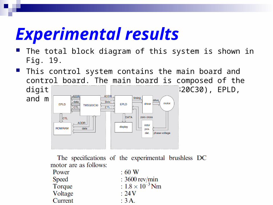
Experimental results The total block diagram of this system is shown in Fig. 19. This control system contains the main board and control board. The
main board is composed of the digital signal processor (DSP,TMS320C30), EPLD, and memories.
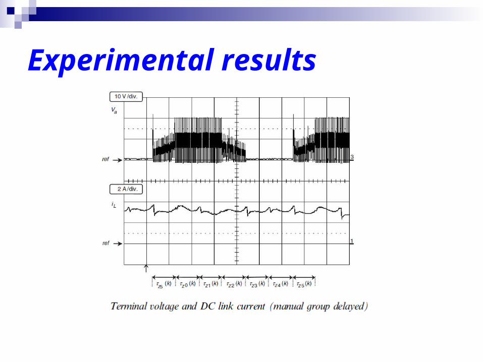
Experimental results
Experimental results
Experimental results
Experimental results
Conclusions The torque characteristics as a function of the rotor position detection
error have been analysed. Key investigation results are summarised in the following:
1. Increasing the rotor position detection error makes the average torque decrease and the torque pulsation increase.
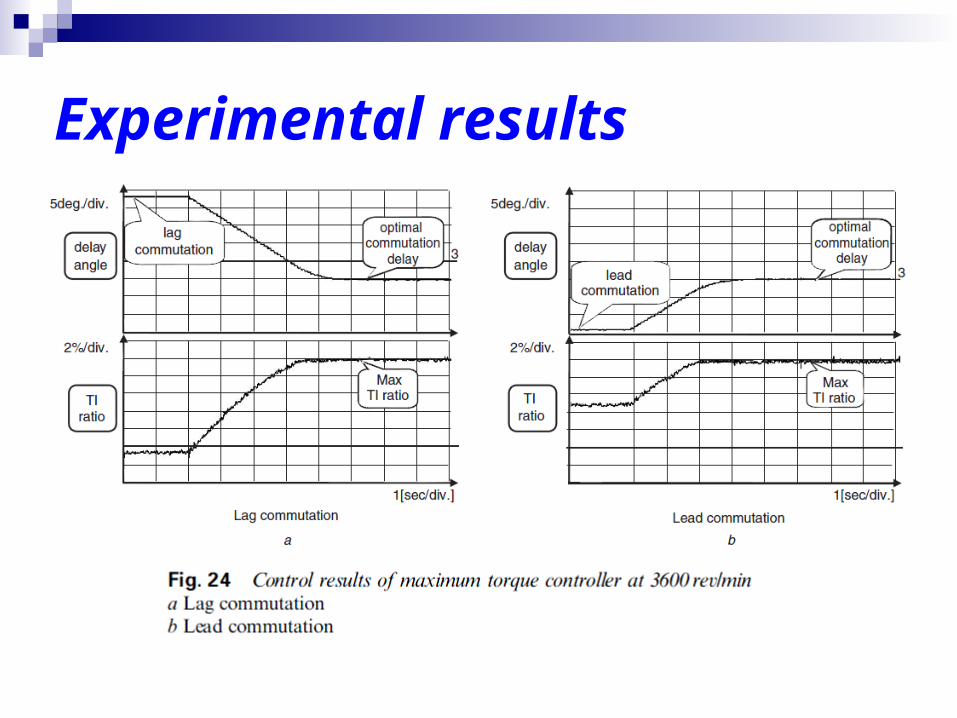
2. The average torque will be maximised by a lead commutation with about half the phase current commutation time.
3. The commutation time is a function of machine parameters and directly affects the rotating speed. Therefore, the timing to generate the maximum torque is changed by the operating speed.
4. The delay angle should be controlled to overcome the adverse effect of the rotor position detection error.
5. The delay angle for the maximum torque can be defined uniquely. Therefore, the delay angle can be controlled to maximise the generation torque.