


Languages
Pages
Legal


Self-priming Pump
Etaprime L
Type Series Booklet

Legal information/Copyright
Type Series Booklet Etaprime L
All rights reserved. The contents provided herein must neither be distributed, copied, reproduced,edited or processed for any other purpose, nor otherwise transmitted, published or made available toa third party without the manufacturer's express written consent.
Subject to technical modification without prior notice.
© KSB Aktiengesellschaft, Frankenthal 17.12.2015

Contents
Self-priming Pump .............................................................................................................................................4
Volute Casing Pumps ...................................................................................................................................................... 4
Etaprime L .................................................................................................................................................................. 4
Main applications ................................................................................................................................................ 4
Fluids handled ...................................................................................................................................................... 4
Operating data .................................................................................................................................................... 4
Designation .......................................................................................................................................................... 4
Further information on the designation ...................................................................................................... 5
Design details ....................................................................................................................................................... 5
Product benefits .................................................................................................................................................. 5
Certifications ........................................................................................................................................................ 5
Overview of fluids handled ................................................................................................................................. 6
Overview of type series ....................................................................................................................................... 7
Priming time ........................................................................................................................................................ 7
Pressure limits ...................................................................................................................................................... 8
Materials .............................................................................................................................................................. 9
Selection charts ................................................................................................................................................. 10
Etaprime L/B, n = 2900 rpm ......................................................................................................................... 10
Etaprime L/B, n = 1450 rpm ......................................................................................................................... 10
Etaprime L/B, n = 3500 rpm ......................................................................................................................... 11
Etaprime L/B, n = 1750 rpm ......................................................................................................................... 11
Dimensions and connections ............................................................................................................................ 12
Sizes 025-025-100 to 040-040-110 (shaft unit 17) – pump ......................................................................... 12
Sizes 025-025-100 to 040-040-110 (shaft unit 17) – pump set ................................................................... 13
Sizes 040-040-140 to 125-125-260 (shaft unit 25 / 35) – pump .................................................................. 14
Sizes 040-040-140 to 125-125-260 (shaft unit 25 / 35) – pump set with coupling .................................... 16
Sizes 040-040-140 to 125-125-260 (shaft unit 25 / 35) – pump set with spacer-type coupling ................ 18
Flange connections ............................................................................................................................................ 20
Interchangeability of Etaprime L and Etaprime B pump components ........................................................... 21
Scope of supply .................................................................................................................................................. 21
Sectional drawing and list of components ...................................................................................................... 22
Etaprime G and C, threaded connection, with bearing housing (SU 17) ................................................. 22
Etaprime G and C, flanged connection, with bearing bracket/grease lubrication (SU 25 and SU 35) ... 24
Etaprime G and C, flanged connection, with bearing bracket/oil lubrication (SU 25 and SU 35) .......... 27
Detailed designation ......................................................................................................................................... 28
Contents
3

Self-priming Pump
Volute Casing Pumps
Etaprime L
Main applications
▪ Spray irrigation systems
▪ Service water supply systems
▪ Drainage
▪ Drainage systems
▪ Fire-fighting systems
▪ Lowering groundwater levels
▪ Domestic water supply
▪ Air-conditioning systems
▪ Cooling circuits
▪ Swimming pools
▪ Water supply systems
Fluids handled
▪ Drinking water
▪ Swimming pool water (0.4 to 1.4 mg/l free chlorine,max. 0.6 mg/l combined chlorine, pH value 6.9 to 7.7,water hardness 10 to 30 °dH, max. salt content 7 g/l)
▪ Fire-fighting water
▪ Seawater
▪ River, lake and groundwater
▪ Brackish water
▪ Condensate
▪ Brine
▪ Oil
▪ Service water
▪ Cleaning agents
▪ Cooling water
Operating data
Operating properties
Characteristic Value
50 Hz 60 HzFlow rate Q [m3/h] ≤ 180 ≤ 150
Q [l/s] ≤ 50 ≤ 41Head H [m] ≤ 85 ≤ 105Fluid temperature T [°C] -30 to +90Operating pressure p [bar] ≤ 10Static suction lift HGeo [m] ≤ 9
Designation
Example: ETPL080-080-200 GCXI10D3
Designation key
Code DescriptionETPL Type series
ETPL Etaprime L080 Nominal suction nozzle diameter [mm]080 Nominal discharge nozzle diameter [mm]200 Nominal impeller diameter [mm]G Casing material
C Stainless steelG Grey cast iron
C Impeller material if different from casingmaterialC Stainless steelG Grey cast iron
X Design- StandardX Special design
I Sealing systemI Single mechanical sealD Double mechanical seal in back-to-
back arrangementT Double mechanical seal in tandem
arrangement10 Seal code
01 Q1Q1VGG08 AQ1VGG1)
09 U3U3VGG10 Q1Q1X4GG11 BQ1EGG
D Scope of supplyA Pump (without motor)B Pump with baseplateC Pump with baseplate, coupling and
coupling guardD Pump with baseplate, coupling,
coupling guard and motor3 Shaft unit
1 SU 172 SU 253 SU 35
1) BQVGG for shaft unit 17
Self-priming PumpVolute Casing Pumps
4 Etaprime L

Further information on the designation
(⇨ Page 28)
Design details
Design
▪ Volute casing pump
▪ Back pull-out design (from size 40-40-140)
▪ Horizontal installation
▪ Self-priming
▪ Single-stage
▪ Single-entry
Pump casing
▪ Radially split volute casing
▪ Volute casing with integrally cast pump feet (from pumpsize 40-40-140)
Impeller type
▪ Open multi-channel impeller
Bearings
▪ Floating bearings: deep groove ball bearings
Shaft seal
▪ The shaft is fitted with a replaceable shaft sleeve in theshaft seal area (from pump size 40-40-140).
▪ Single and double mechanical seals to EN 12756
Bearings used
Standard bearings
Version Bearingbracket
Rolling element bearing
Pump end Drive endStandardbearings(greaselubrication)
SU 17 3203 C3 6203 2RSSU 25 6305 2Z C3 6305 2Z C3SU 35 6307 2Z C3 6307 2Z C3
Standardbearings (oillubrication)
SU 17 - -SU 25 6305 C3 6305 C3SU 35 6307 C3 6307 C3
Lubrication:
▪ Grease lubrication
▪ Oil lubrication
Drive
▪ KSB IEC frame standardised IE3 motor (from 0.75 kW)
▪ 230/400 V up to 2.2 kW and 400/690 V from 3 kW
▪ 60 Hz winding, 440 - 480 V
▪ Type of construction B3
▪ IP55 enclosure
▪ Thermal class F with temperature sensor, 3 PTC thermistors
▪ Mode of operation: continuous operation S1
Product benefits
▪ Maintenance-free mechanical seal ensures operatingreliability
▪ Easy to dismantle due to back pull-out design; no need toremove the pump casing from the piping
▪ Good suction performance, self-priming up to 9 m suctionlift, also suitable for applications with relatively poor inletconditions (i.e. low or negative inlet pressure) and forhandling fluids with entrained gas.
▪ Optimised hydraulic components for high efficiency helpreduce energy consumption
Certifications
Overview
Label Effective in: NoteAll countries Certified quality management
to ISO 9001
Self-priming PumpVolute Casing Pumps
Etaprime L 5

Overview of fluids handled
Table of fluids handled and associated material combinations ✘ = standard
Fluid handled Temperature Materials Shaft seal
Mec
han
ical
sea
ld
esig
n c
od
e
Comments
Casing / impeller Mechanical seal
Gre
y ca
st ir
on
/gre
y ca
st ir
on
Gre
y ca
st ir
on
/C
r-N
i-M
o c
ast
stee
l C
rNiM
o c
ast
stee
l/C
rNiM
o c
ast
stee
l
Q1Q
1VG
G
AQ
1VG
G2)
BQ
VG
G3)
U3U
3VG
G
Q1Q
1X4G
G
BQ
1EG
G2)
Q12
Q1M
1GG
Design code
[°C] G GC C 01 8 9 10 11 704)
Water Industrial waste water Analysis of the fluid
handled requiredAmmonia water (ammoniasolution)
≤ 40; conc. ≤ 10 % ✘ ✘ Tandem seal Q1Q1EGGrequired.Quench liquid: usedsuitable water.
Brackish water ≤ 25 ✘ ✘ 10 Fire-fighting water5) ≤ 60 ✘ ✘ 10 Condensate2) ≤ 90 ✘ ✘ 11 Condensate, not conditioned ≤ 90 ✘ ✘ 11 Cooling water (withoutantifreeze)5)
≤ 60 ✘ ✘ 10 Open circuit: CL 10required
Cooling water pH ≥ 7.5 (with antifreeze)5)6)
≥ -30 p ≤ 10 bar≤ 90
✘ ✘ 11 Open circuit: CL 11required
Slightly contaminated water5) ≤ 60 ✘ ✘ 10 Seawater ≤ 25 ✘ ✘ 10 Surface water5) ≤ 40 ✘ ✘ 8 Analysis of the fluids
handled requiredPure water7) ≤ 60 ✘ ✘ 11 Untreated water5) ≤ 60 ✘ ✘ 10 Swimming pool water (freshwater)5)
≤ 60 ✘ ✘ 10 Also applies torequirements as perDIN 19643
Dam water5) ≤ 60 ✘ ✘ 10 If solids are contained,contact KSB.
Drinking water ≤ 60 ✘ 11 Partly desalinated water2) ≤ 90 ✘ ✘ 11 Fully desalinated water ≤ 90 ✘ ✘ 11 Requirements for ultra-
pure water cannot bemet.
Fully desalinated water asboiler feed water2)
≤ 90 ✘ ✘ 11 Refrigerants, cooling brines Cooling brine; inorganic, pH value > 7.5, inhibited
≥ -30 ≤ 25
✘ ✘ 11 Water with antifreeze,pH value > 7.55)6)
≥ -30 ≤ 90
✘ ✘ 11 Oils/emulsions Drilling/grinding emulsion ≤ 60 ✘ ✘ 9 Oil-water emulsion ≤ 60 ✘ ✘ 9 Cleaning agents Lyes for bottle rinsers8) ≤ 90 ✘ ✘ 10 EPDM only if oil-free
2) Treatment to VdTÜV 1466; additional requirement: O2 ≤ 0.02 mg/l3) Only applies to shaft unit 17.4) Special mechanical seal design5) General criteria for results of water analysis: pH value ≥ 7; chloride content (Cl) ≤ 250 mg/kg. Chlorine (Cl2) ≤ 0.6 mg/kg.6) Antifreeze on ethylene glycol basis with inhibitors. Content: 20 % to 50 % (e.g. Antifrogen N)7) No ultra-pure water! Conductivity at 25 °C: ≤ 800 μS/cm
Self-priming PumpVolute Casing Pumps
6 Etaprime L

Fluid handled Temperature Materials Shaft seal
Mec
han
ical
sea
ld
esig
n c
od
e
Comments
Casing / impeller Mechanical seal
Gre
y ca
st ir
on
/gre
y ca
st ir
on
Gre
y ca
st ir
on
/C
r-N
i-M
o c
ast
stee
l C
rNiM
o c
ast
stee
l/C
rNiM
o c
ast
stee
l
Q1Q
1VG
G
AQ
1VG
G2)
BQ
VG
G3)
U3U
3VG
G
Q1Q
1X4G
G
BQ
1EG
G2)
Q12
Q1M
1GG
Design code
[°C] G GC C 01 8 9 10 11 704)
Acids Acetic acid ≤ 60; conc. ≤ 5 %
≤ 60; conc. ≤ 10 % ✘ ✘ 11
Alum, potassium aluminiumsulphate up to 3 %
≤ 80 ✘ ✘ 01
Overview of type series
Available sizes and designs
Size Shaft unit Etaprime L Etaprime B
G GC, C G GC, C032-032-100 17 S / T - S / T -032-032-120 17 S / T S / T S / T S / T040-040-110 17 S / T S / T S / T S / T040-040-140 25 S / T / B S / T / B S / T / B S / T / B050-050-130 25 S / T / B S / T / B S / T / B S / T / B050-050-160 25 S / T / B S / T / B S / T / B S / T / B065-065-150 25 S / T / B S / T / B S / T / B S / T / B065-065-180 35 S / T / B S / T / B S / T / B S / T / B080-080-170 35 S / T / B S / T / B S / T / B S / T / B080-080-190 35 S / T / B - S / T / B -080-080-200 35 S / T / B S / T / B S / T / B S / T / B100-100-240.1 35 S / T / B - S / T / B -100-100-240 35 S / T / B - - -125-125-260 35 S / T / B - - -
E = Single mechanical seal (standard design)T = Available with double mechanical seal in tandem arrangementB = Available with double mechanical seal in back-to-back arrangement- = Size not available
Priming time
For a 1-metre horizontal length of the suction line and DNsuction line = DN pump, the priming times are as follows.
When handling gaseous fluids, fluids which tend to froth orwater with a temperature T > 60 °C, the pump will not be self-priming. In such cases, a check valve must be installed in thesuction line.
2) Treatment to VdTÜV 1466; additional requirement: O2 ≤ 0.02 mg/l3) Only applies to shaft unit 17.4) Special mechanical seal design8) With 2 % sodium hydroxide
Self-priming PumpVolute Casing Pumps
Etaprime L 7

0,5 - 1 m
H1geo
≤ 1 m
Distances of suction line and discharge line
Size9)
Shaf
t u
nit
Priming time [sec]
at a speed n = 2900 rpm
at a static suction lift H1geo of ... m
2 m 4 m 5 m 6 m 7 m 8 m025-025-100 17 40 145 415 - - -032-032-120 30 90 135 190 255 360040-040-110 60 100 215 420 - -040-040-140 25 30 70 125 220 355 600050-050-130 50 120 195 260 345 440050-050-160 30 70 105 170 265 430065-065-150 60 120 165 260 375 570065-065-180 35 30 50 75 100 145 200080-080-170 50 100 135 180 225 310080-080-190 40 70 105 160 185 240080-080-200 30 50 75 105 155 200
100-100-240.1 30 70 95 120 150 190100-100-240 35 70 85 110 160 -125-125-260 35 80 105 130 160 190
Size9)
Shaf
t u
nit
Priming time [sec]
at a speed n = 3500 rpm
at a static suction lift H1geo of ... m
2 m 4 m 5 m 6 m 7 m 8 m025-025-100 17 30 85 135 - - -032-032-120 20 60 105 140 175 250040-040-110 30 85 125 200 265 470040-040-140 25 25 50 85 120 145 230050-050-130 30 90 140 190 245 300050-050-160 25 55 75 150 215 280065-065-150 40 80 125 170 225 370
Size9)
Shaf
t u
nit
Priming time [sec]
at a speed n = 3500 rpm
at a static suction lift H1geo of ... m
2 m 4 m 5 m 6 m 7 m 8 m065-065-180 35 20 40 65 90 105 150080-080-170 30 80 105 130 165 220080-080-190 30 55 75 100 125 160080-080-200 25 40 55 80 125 160
100-100-240.1 25 60 85 115 145 180100-100-240 25 70 85 100 155 360
Size9)
Shaf
t u
nit
Priming time [sec]
at a speed n = 1450 rpm
at a static suction lift H1geo of ... m
1 m 2 m 3 m 4 m 5 m 6 m 7 m 8 m025-025-100 17 130 - - - - - - -032-032-120 100 210 - - - - - -040-040-110 120 - - - - - - -040-040-140 25 130 - - - - - - -050-050-130 210 410 - - - - - -050-050-160 210 430 - - - - - -065-065-150 190 350 540 - - - - -065-065-180 35 90 140 220 370 - - - -080-080-170 110 180 280 480 - - - -080-080-190 100 110 200 310 - - - -080-080-200 70 110 190 270 320 420 - -
100-100-240.1 130 150 220 300 440 - - -100-100-240 110 160 270 480 - - - -125-125-260 60 70 110 160 200 330 430 610
Size9)
Shaf
t u
nit
Priming time [sec]
at a speed n = 1750 rpm
at a static suction lift H1geo of ... m
1 m 2 m 3 m 4 m 5 m 6 m 7 m 8 m025-025-100 17 70 170 - - - - - -032-032-120 80 150 260 - - - - -040-040-110 90 180 - - - - - -040-040-140 25 80 150 200 - - - - -050-050-130 130 240 380 - - - - -050-050-160 130 260 480 - - - - -065-065-150 140 260 350 430 - - - -065-065-180 35 80 110 170 220 330 - - -080-080-170 90 130 200 320 480 - - -080-080-190 80 100 130 160 210 390 - -080-080-200 60 100 160 230 280 350 - -
100-100-240.1 90 110 140 210 260 400 - -100-100-240 80 100 140 200 300 - - -125-125-260 50 60 80 115 170 220 300 400
Pressure limits
Size Dischargepressure p 2
10)
[bar]
Test pressure11)
[bar]
All sizes 10,0 15,0
9) Stainless steel variant not available for all pump sizes.10) The sum of inlet pressure and shut-off head must not exceed the values indicated.11) The casing components are checked for leakage by means of internal pressure tests to ZN 1650 with water.
Self-priming PumpVolute Casing Pumps
8 Etaprime L
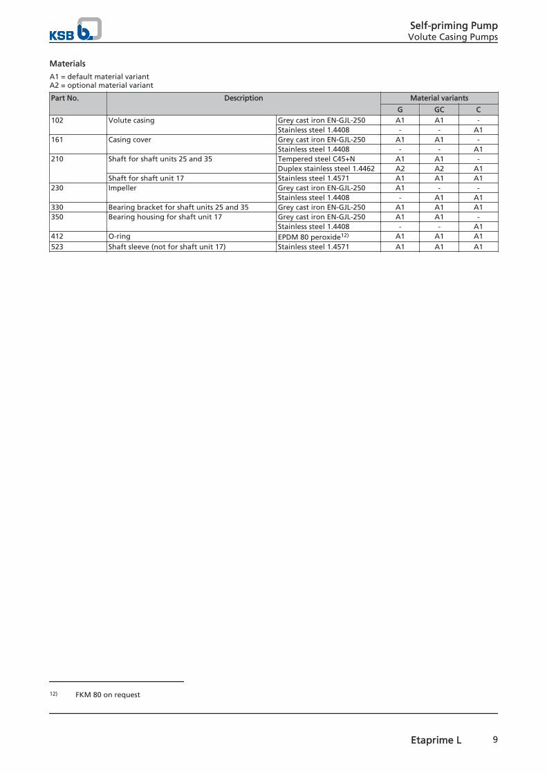
Materials
A1 = default material variantA2 = optional material variant
Part No. Description Material variants
G GC C102 Volute casing Grey cast iron EN-GJL-250 A1 A1 -
Stainless steel 1.4408 - - A1161 Casing cover Grey cast iron EN-GJL-250 A1 A1 -
Stainless steel 1.4408 - - A1210 Shaft for shaft units 25 and 35 Tempered steel C45+N A1 A1 -
Duplex stainless steel 1.4462 A2 A2 A1Shaft for shaft unit 17 Stainless steel 1.4571 A1 A1 A1
230 Impeller Grey cast iron EN-GJL-250 A1 - -Stainless steel 1.4408 - A1 A1
330 Bearing bracket for shaft units 25 and 35 Grey cast iron EN-GJL-250 A1 A1 A1350 Bearing housing for shaft unit 17 Grey cast iron EN-GJL-250 A1 A1 -
Stainless steel 1.4408 - - A1412 O-ring EPDM 80 peroxide12) A1 A1 A1523 Shaft sleeve (not for shaft unit 17) Stainless steel 1.4571 A1 A1 A1
12) FKM 80 on request
Self-priming PumpVolute Casing Pumps
Etaprime L 9

Selection charts
Etaprime L/B, n = 2900 rpm
H[m]
Q[m³/h]5 10 20 30 40 50 100 200Q[m³/h]
30 40 50 100 200 300 400 500US.gpm
20 30 40 50 100 200 300 400 500IM.gpm
3
4
5
10
20
30
40
50
90
H[m]
10
20
30
40
50
100
200
ft
2 3 4 5 10 20 30 40 50l/s
25-25-100 L/B
32-32-120 L/B *
40-40-110 L/B *
40-40-140 L/B *
50-50-130 L/B *
50-50-160 L/B *
65-65-150 L/B *
65-65-180 L/B *
80-80-170 L/B *
80-80-190 L/B
80-80-200 L/B *
100-100-240 L
100-100-240.1 L/B
125-125-260 L
* Also available in stainless steel material variant
Etaprime L/B, n = 1450 rpm
H[m]
Q[m³/h]2 3 4 5 10 20 30 40 50 90Q[m³/h]
10 20 30 40 50 100 200 300US.gpm
10 20 30 40 50 100 200 300IM.gpm
1
2
3
4
5
10
20
25
H[m]
4
5
10
20
30
40
50
ft
1 2 3 4 5 10 20l/s
25-25-100 L/B
32-32-120 L/B *
40-40-110 L/B *
40-40-140 L/B *
50-50-130 L/B *
50-50-160 L/B *
65-65-150 L/B *
65-65-180 L/B *
80-80-170 L/B *
80-80-190 L/B
80-80-200 L/B *
100-100-240 L
100-100-240.1 L/B
125-125-260 L
* Also available in stainless steel material variant
Self-priming PumpVolute Casing Pumps
10 Etaprime L

Etaprime L/B, n = 3500 rpm
H[m]
Q[m³/h]10 20 30 40 50 1007 160Q[m³/h]
40 50 100 200 300 400 500US.gpm
30 40 50 100 200 300 400 500IM.gpm
5
10
20
30
40
50
100
4.5
120
H[m]
20
30
40
50
100
200
300
ft
2 3 4 5 10 20 30 40l/s
25-25-100 L/B
32-32-120 L/B *
40-40-110 L/B *
40-40-140 L/B *
50-50-130 L/B *
50-50-160 L/B *
65-65-150 L/B *
65-65-180 L/B *
80-80-170 L/B *
80-80-190 L/B
80-80-200 L/B *
100-100-240 L
100-100-240.1 L/B
* Also available in stainless steel material variant
Etaprime L/B, n = 1750 rpm
H[m]
Q[m³/h]3 4 5 10 20 30 40 50 100 120Q[m³/h]
20 30 40 50 100 200 300 400 500US.gpm
20 30 40 50 100 200 300 400IM.gpm
1
2
3
4
5
10
20
30
35
H[m]
4
5
10
20
30
40
50
100
ft
1 2 3 4 5 10 20 30l/s
25-25-100 L/B
32-32-120 L/B *
40-40-110 L/B *
40-40-140 L/B *
50-50-130 L/B *
50-50-160 L/B *
65-65-150 L/B *
65-65-180 L/B *
80-80-170 L/B *
80-80-190 L/B
80-80-200 L/B *
100-100-240 L
100-100-240.1 L/B
125-125-260 L
* Also available in stainless steel material variant
Self-priming PumpVolute Casing Pumps
Etaprime L 11

Dimensions and connections
Sizes 025-025-100 to 040-040-110 (shaft unit 17) – pump
5
16
14k6
b1 b2
6B
6D6DDN
DN
a f
h2
h1
h3
80
25
11
80w
60
35 12
65105
UG
1564
710_
CD
2_D
01 /0
1
Dimensions of sizes 025-025-100 to 040-040-110 (shaft unit 17) – pump
6B Fluid drain 6D Fluid priming and venting
Connections
Size 6 B13) 6D13)
025-025-100 G 1/8 G 3/8032-032-120 G 1/8 G 3/8040-040-110 G 1/8 G 3/8
Pump dimensions [mm]
Size Connection Pump
Standard Optional a b1 b2 f h1 h2 h3 w
DN14) DN15)
020-025-100 Rp 1 NPT 1 70 104 95 169 220 38 265 89032-032-120 Rp 1 1/4 NPT 1 1/4 95 118 95 165 229 46 286 85040-040-110 Rp 1 1/2 NPT 1 1/2 105 118 110 171 235 55 312 91
13) G = ISO 228/114) Standard connection to ISO 7/115) Optional connection to ASME B1.20.1
Self-priming PumpVolute Casing Pumps
12 Etaprime L

Sizes 025-025-100 to 040-040-110 (shaft unit 17) – pump set
150
b1
b2
6B
6D6DDN
DN
a f
h2
h1
80
4
M12×25080
i
UG
1564
702_
CD
2_D
01 /0
1
b3
l1
l2
l3
Dimensions of sizes 025-025-100 to 040-040-110 (shaft unit 17) – pump set
6B Fluid drain 6D Fluid priming and venting
Pump set dimensions [mm]
Size n PN
IEC
mo
tor
Connection Pump set
1450
1750
2900
3500
Stan
dar
d
Op
tio
nal a f h1 h2 b1 b2 b3 i l1 l2 l3
[rpm] [kW] DN16) DN17)
025-025-100 ✘ ✘ - - 0,37 71 Rp 1 NPT 1 70 169 295 38 350 160 200 41,5 570 360 420025-025-100 ✘ ✘ - - 0,55 80M Rp 1 NPT 1 70 169 295 38 350 160 200 41,5 570 360 420025-025-100 - - ✘ - 0,55 71 Rp 1 NPT 1 70 169 295 38 350 160 200 41,5 570 360 420025-025-100 - - - ✘ 0,75 80M Rp 1 NPT 1 70 169 295 38 350 160 200 41,5 570 360 420025-025-100 - - - ✘ 1,10 80M Rp 1 NPT 1 70 169 295 38 350 160 200 41,5 570 360 420 032-032-120 ✘ ✘ - - 0,37 71 R 1 1/4 NPT 1 1/4 95 165 304 46 350 160 200 41,5 570 360 420032-032-120 ✘ ✘ - - 0,55 80M R 1 1/4 NPT 1 1/4 95 165 304 46 350 160 200 41,5 570 360 420032-032-120 - - ✘ - 1,10 80M R 1 1/4 NPT 1 1/4 95 165 304 46 350 160 200 41,5 570 360 420032-032-120 - - - ✘ 2,20 90L R 1 1/4 NPT 1 1/4 95 165 314 46 350 160 200 41,5 570 360 420 040-040-110 ✘ ✘ - - 0,37 71 Rp 1 1/2 NPT 1 1/2 105 171 310 55 350 160 200 41,5 570 360 420040-040-110 ✘ ✘ - - 0,55 80M Rp 1 1/2 NPT 1 1/2 105 171 310 55 350 160 200 41,5 570 360 420040-040-110 - - ✘ - 1,10 80M Rp 1 1/2 NPT 1 1/2 105 171 310 55 350 160 200 41,5 570 360 420040-040-110 - - - ✘ 1,50 90S Rp 1 1/2 NPT 1 1/2 105 171 320 55 350 160 200 41,5 570 360 420
16) Standard connection to ISO 7/117) Optional connection to ASME B1.20.1
Self-priming PumpVolute Casing Pumps
Etaprime L 13
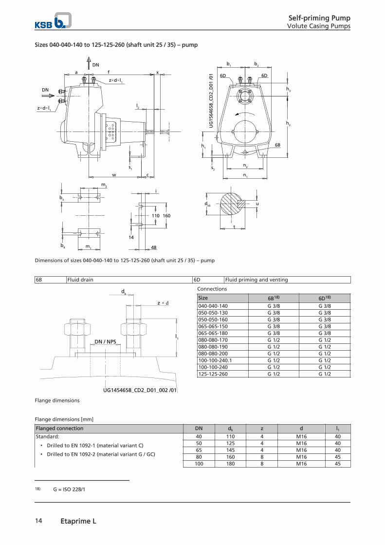
Sizes 040-040-140 to 125-125-260 (shaft unit 25 / 35) – pump
s2
n2
6B
6D6D
DN
DN
a f
h2
h1
w
z×d×l1
i
UG
1564
658_
CD
2_D
01 /0
1
n1c
h3
s1
b4
b3
m1
m2
b2b1
z×d×l1
udk6
t
l2
110 160
48
14
x
Dimensions of sizes 040-040-140 to 125-125-260 (shaft unit 25 / 35) – pump
6B Fluid drain 6D Fluid priming and venting
l1DN / NPS
dk
z × d
UG1454658_CD2_D01_002 /01
Flange dimensions
Connections
Size 6B18) 6D18)
040-040-140 G 3/8 G 3/8050-050-130 G 3/8 G 3/8050-050-160 G 3/8 G 3/8065-065-150 G 3/8 G 3/8065-065-180 G 3/8 G 3/8080-080-170 G 1/2 G 1/2080-080-190 G 1/2 G 1/2080-080-200 G 1/2 G 1/2100-100-240.1 G 1/2 G 1/2100-100-240 G 1/2 G 1/2125-125-260 G 1/2 G 1/2
Flange dimensions [mm]
Flanged connection DN dk z d l1Standard:
▪ Drilled to EN 1092-1 (material variant C)
▪ Drilled to EN 1092-2 (material variant G / GC)
40 110 4 M16 4050 125 4 M16 4065 145 4 M16 4080 160 8 M16 45100 180 8 M16 45
18) G = ISO 228/1
Self-priming PumpVolute Casing Pumps
14 Etaprime L

Flanged connection DN dk z d l1125 210 8 M16 45
Optional:
▪ Drilled to ASME B16.1 (material variant G / GC)
▪ Drilled to ASME B16.5 (material variant C)
NPS 1 1/2 98,6 4 UNC 1/2-13 40NPS 2 120,7 4 UNC 5/8-11 40
NPS 2 1/2 139,7 4 UNC 5/8-11 40NPS 3 152,4 4 UNC 5/8-11 40NPS 4 190,5 8 UNC 5/8-11 45NPS 5 215,9 8 UNC 3/4-10 45
Pump dimensions [mm]
Size Pump
DN a b1 b2 b3 b4 c dK6 f h1 h2 h3 i l2 m1 m2 n1 n2 s1 s2 t u w
040-040-140 40 115 115 128 57 16 100 24 370 112 284 73 23 50 100 70 220 160 4 13 27 8 270050-050-130 50 130 138 128 55 16 100 24 370 132 317 78 23 50 100 70 250 190 4 17 27 8 270050-050-160 50 130 145 126 55 16 100 24 370 132 327 75 23 50 100 70 250 190 4 17 27 8 270065-065-150 65 140 155 149 55 16 100 24 370 160 370 85 25 50 125 95 270 212 6 20 27 8 270065-065-180 65 140 158 138 55 16 130 32 490 160 376 89 23 80 125 95 270 212 4 18 35 10 360080-080-170 80 156 173 168 65 18 130 32 490 160 380 104 23 80 140 106 310 240 4 18 35 10 360080-080-190 80 170 188 181 65 20 130 32 490 180 420 107 24 80 160 120 345 280 6 22 35 10 360080-080-200 80 154 172 152 65 20 130 32 490 160 378 107 24 80 140 100 285 220 4 22 35 10 360100-100-240.1 100 182 203 178 68 20 130 32 478 200 457 127 24 80 140 100 330 260 6 18 35 10 348100-100-240 100 182 203 178 68 20 130 32 478 200 457 127 24 80 140 100 330 260 6 18 35 10 348125-125-260 125 204 227 197 70 20 130 32 478 200 486 142 24 80 140 100 340 270 6 18 35 10 348
Self-priming PumpVolute Casing Pumps
Etaprime L 15
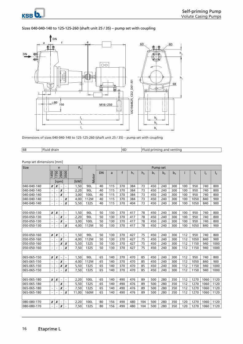
Sizes 040-040-140 to 125-125-260 (shaft unit 25 / 35) – pump set with coupling
l2
6B
6D 6D
DN
DN
a f
h2
h1
UG
1564
625_
CD
2_D
01 /0
1
l3
b1
b3
4
M16×250
b2
l1
80
i
150
Dimensions of sizes 040-040-140 to 125-125-260 (shaft unit 25 / 35) – pump set with coupling
6B Fluid drain 6D Fluid priming and venting
Pump set dimensions [mm]
Size n PN
Mo
tor
Pump set
1450
1750
2900
3500 DN a f h1 h2 b1 b2 b3 i l1 l2 l3
[rpm] [kW]040-040-140 ✘ ✘ - - 1,50 90L 40 115 370 384 73 450 240 300 100 950 740 800040-040-140 - - ✘ - 2,20 90L 40 115 370 384 73 450 240 300 100 950 740 800040-040-140 - - ✘ - 3,00 100L 40 115 370 384 73 450 240 300 100 950 740 800040-040-140 - - - ✘ 4,00 112M 40 115 370 384 73 450 240 300 100 1050 840 900040-040-140 - - - ✘ 5,50 132S 40 115 370 404 73 450 240 300 100 1050 840 900 050-050-130 ✘ ✘ - - 1,50 90L 50 130 370 417 78 450 240 300 100 950 740 800050-050-130 - - ✘ - 2,20 90L 50 130 370 417 78 450 240 300 100 950 740 800050-050-130 - - ✘ - 3,00 100L 50 130 370 417 78 450 240 300 100 950 740 800050-050-130 - - - ✘ 4,00 112M 50 130 370 417 78 450 240 300 100 1050 840 900 050-050-160 ✘ ✘ - - 1,50 90L 50 130 370 427 75 450 240 300 112 950 740 800050-050-160 - - ✘ - 4,00 112M 50 130 370 427 75 450 240 300 112 1050 840 900050-050-160 - - ✘ ✘ 5,50 132S 50 130 370 427 75 450 240 300 112 1150 940 1000050-050-160 - - - ✘ 7,50 132S 50 130 370 427 75 450 240 300 112 1150 940 1000 065-065-150 ✘ ✘ - - 1,50 90L 65 140 370 470 85 450 240 300 112 950 740 800065-065-150 - - ✘ - 4,00 112M 65 140 370 470 85 450 240 300 112 1050 840 900065-065-150 - - ✘ ✘ 5,50 132S 65 140 370 470 85 450 240 300 112 1150 940 1000065-065-150 - - - ✘ 7,50 132S 65 140 370 470 85 450 240 300 112 1150 940 1000 065-065-180 ✘ ✘ - - 2,20 100L 65 140 490 476 89 500 280 350 112 1270 1060 1120065-065-180 - - ✘ - 5,50 132S 65 140 490 476 89 500 280 350 112 1270 1060 1120065-065-180 - - ✘ - 7,50 132S 65 140 490 476 89 500 280 350 112 1270 1060 1120065-065-180 - - - ✘ 11,00 160M 65 140 490 476 89 500 280 350 112 1270 1060 1120 080-080-170 ✘ ✘ - - 2,20 100L 80 156 490 480 104 500 280 350 120 1270 1060 1120080-080-170 - - ✘ - 7,50 132S 80 156 490 480 104 500 280 350 120 1270 1060 1120
Self-priming PumpVolute Casing Pumps
16 Etaprime L

Size n PN
Mo
tor
Pump set
1450
1750
2900
3500 DN a f h1 h2 b1 b2 b3 i l1 l2 l3
[rpm] [kW]080-080-170 - - - ✘ 11,00 160M 80 156 490 480 104 500 280 350 120 1270 1060 1120080-080-170 - - - ✘ 15,00 160M 80 156 490 480 104 500 280 350 120 1270 1060 1120 080-080-190 ✘ ✘ - - 2,20 100L 80 170 490 520 107 500 280 350 130 1270 1060 1120080-080-190 ✘ ✘ - - 3,00 100L 80 170 490 520 107 500 280 350 130 1270 1060 1120080-080-190 - - ✘ - 11,00 160M 80 170 490 520 107 500 280 350 130 1400 1190 1250080-080-190 - - - ✘ 15,00 160M 80 170 490 520 107 500 280 350 130 1400 1190 1250080-080-190 - - - ✘ 18,50 160L 80 170 490 520 107 500 280 350 130 1400 1190 1250 080-080-200 ✘ ✘ - - 2,20 100L 80 154 490 478 107 500 280 350 120 1270 1060 1120080-080-200 - - ✘ - 11,00 160M 80 154 490 478 107 500 280 350 120 1400 1190 1250080-080-200 - - - ✘ 15,00 160M 80 154 490 478 107 500 280 350 120 1400 1190 1250080-080-200 - - - ✘ 18,50 160L 80 154 490 478 107 500 280 350 120 1400 1190 1250 100-100-240.1 ✘ ✘ - - 2,20 100L 100 182 478 557 127 500 280 350 120 1270 1060 1120100-100-240.1 ✘ ✘ - - 3,00 100L 100 182 478 557 127 500 280 350 120 1270 1060 1120100-100-240.1 ✘ ✘ - - 4,00 112M 100 182 478 557 127 500 280 350 120 1270 1060 1120100-100-240.1 - - ✘ - 15,00 160M 100 182 478 557 127 500 280 350 120 1270 1060 1120100-100-240.1 - - ✘ - 18,50 160L 100 182 478 557 127 500 280 350 120 1400 1190 1250100-100-240.1 - - - ✘ 22,00 180M 100 182 478 567 127 550 320 400 120 1400 1190 1250100-100-240.1 - - - ✘ 30,00 200L 100 182 478 567 127 550 320 400 120 1400 1190 1250 100-100-240 ✘ ✘ - - 3,00 100L 100 182 478 557 127 500 280 350 120 1270 1060 1120100-100-240 ✘ ✘ - - 4,00 112M 100 182 478 557 127 500 280 350 120 1270 1060 1120100-100-240 ✘ ✘ - - 5,50 132S 100 182 478 557 127 500 280 350 120 1270 1060 1120100-100-240 - - ✘ - 22,00 180M 100 182 478 567 127 550 320 400 120 1400 1190 1250100-100-240 - - ✘ - 30,00 200L 100 182 478 567 127 550 320 400 120 1400 1190 1250100-100-240 - - - ✘ 37,00 200L 100 182 478 567 127 550 320 400 120 1400 1190 1250 125-125-260 ✘ ✘ - - 5,50 132S 125 204 478 586 142 500 280 350 120 1270 1060 1120125-125-260 ✘ ✘ - - 7,50 132M 125 204 478 586 142 500 280 350 120 1270 1060 1120125-125-260 ✘ ✘ - - 11,00 160M 125 204 478 596 142 550 320 400 120 1400 1190 1250125-125-260 - - ✘ - 30,00 200L 125 204 478 596 142 550 320 400 120 1400 1190 1250125-125-260 - - ✘ - 37,00 200L 125 204 478 596 142 550 320 400 120 1400 1190 1250
Self-priming PumpVolute Casing Pumps
Etaprime L 17

Sizes 040-040-140 to 125-125-260 (shaft unit 25 / 35) – pump set with spacer-type coupling
l2
6B
6D 6DDN
DN
a f
h2
h1
UG
1564
651_
CD
2_D
01 /0
1
l3
b1
b3
4
M16×250150
b2
l1
80
i
x
Dimensions of sizes 040-040-140 to 125-125-260 (shaft unit 25 / 35) – pump set with spacer-type coupling
6B Fluid drain 6D Fluid priming and venting
Pump set dimensions [mm]
Size n PN
Mo
tor
Pump set
1450
1750
2900
3500 DN a f h1 h2 b1 b2 b3 i l1 l2 l3 x
[rpm] [kW]040-040-140 ✘ ✘ - - 1,50 90L 40 115 370 384 73 450 240 300 100 1050 840 900 100040-040-140 - - ✘ - 2,20 90L 40 115 370 384 73 450 240 300 100 1050 840 900 100040-040-140 - - ✘ - 3,00 100L 40 115 370 384 73 450 240 300 100 1050 840 900 100040-040-140 - - - ✘ 4,00 112M 40 115 370 384 73 450 240 300 100 1150 940 1000 100040-040-140 - - - ✘ 5,50 132S 40 115 370 404 73 450 240 300 100 1150 940 1000 100 050-050-130 ✘ ✘ - - 1,50 90L 50 130 370 417 78 450 240 300 100 1050 840 900 100050-050-130 - - ✘ - 2,20 90L 50 130 370 417 78 450 240 300 100 1050 840 900 100050-050-130 - - ✘ - 3,00 100L 50 130 370 417 78 450 240 300 100 1050 840 900 100050-050-130 - - - ✘ 4,00 112M 50 130 370 417 78 450 240 300 100 1150 940 1000 100 050-050-160 ✘ ✘ - - 1,50 90L 50 130 370 427 75 450 240 300 112 1050 840 900 100050-050-160 - - ✘ - 4,00 112M 50 130 370 427 75 450 240 300 112 1150 940 1000 100050-050-160 - - ✘ ✘ 5,50 132S 50 130 370 427 75 500 280 350 112 1270 1060 1120 100050-050-160 - - - ✘ 7,50 132S 50 130 370 427 75 500 280 350 112 1270 1060 1120 100 065-065-150 ✘ ✘ - - 1,50 90L 65 140 370 470 85 450 240 300 112 1050 840 900 100065-065-150 - - ✘ - 4,00 112M 65 140 370 470 85 450 240 300 112 1150 940 1000 100065-065-150 - - ✘ ✘ 5,50 132S 65 140 370 470 85 500 280 350 112 1270 1060 1120 100065-065-150 - - - ✘ 7,50 132S 65 140 370 470 85 500 280 350 112 1270 1060 1120 100 065-065-180 ✘ ✘ - - 2,20 100L 65 140 490 476 89 500 280 350 112 1400 1190 1250 140065-065-180 - - ✘ - 5,50 132S 65 140 490 476 89 500 280 350 112 1400 1190 1250 140065-065-180 - - ✘ - 7,50 132S 65 140 490 476 89 500 280 350 112 1400 1190 1250 140065-065-180 - - - ✘ 11,00 160M 65 140 490 476 89 500 280 350 112 1400 1190 1250 140 080-080-170 ✘ ✘ - - 2,20 100L 80 156 490 480 104 500 280 350 120 1400 1190 1250 140080-080-170 - - ✘ - 7,50 132S 80 156 490 480 104 500 280 350 120 1400 1190 1250 140
Self-priming PumpVolute Casing Pumps
18 Etaprime L

Size n PN
Mo
tor
Pump set
1450
1750
2900
3500 DN a f h1 h2 b1 b2 b3 i l1 l2 l3 x
[rpm] [kW]080-080-170 - - - ✘ 11,00 160M 80 156 490 480 104 500 280 350 120 1400 1190 1250 140080-080-170 - - - ✘ 15,00 160M 80 156 490 480 104 500 280 350 120 1400 1190 1250 140 080-080-190 ✘ ✘ - - 2,20 100L 80 170 490 520 107 550 280 350 120 1400 1190 1250 140080-080-190 ✘ ✘ - - 3,00 100L 80 170 490 520 107 550 280 350 120 1400 1190 1250 140080-080-190 - - ✘ - 11,00 160M 80 170 490 530 107 550 320 400 130 1570 1360 1420 140080-080-190 - - - ✘ 15,00 160M 80 170 490 530 107 550 320 400 130 1570 1360 1420 140080-080-190 - - - ✘ 18,50 160L 80 170 490 530 107 550 320 400 130 1570 1360 1420 140 080-080-200 ✘ ✘ - - 2,20 100L 80 154 490 478 107 500 280 350 120 1400 1190 1250 140080-080-200 - - ✘ - 11,00 160M 80 154 490 488 107 550 320 400 120 1570 1360 1420 140080-080-200 - - - ✘ 15,00 160M 80 154 490 488 107 550 320 400 120 1570 1360 1420 140080-080-200 - - - ✘ 18,50 160L 80 154 490 488 107 550 320 400 120 1570 1360 1420 140 100-100-240.1 ✘ ✘ - - 2,20 100L 100 182 478 557 127 500 280 350 120 1400 1190 1250 140100-100-240.1 ✘ ✘ - - 3,00 100L 100 182 478 557 127 500 280 350 120 1400 1190 1250 140100-100-240.1 ✘ ✘ - - 4,00 112M 100 182 478 557 127 500 280 350 120 1400 1190 1250 140100-100-240.1 - - ✘ - 15,00 160M 100 182 478 557 127 500 280 350 120 1400 1190 1250 140100-100-240.1 - - ✘ - 18,50 160L 100 182 478 567 127 550 320 400 120 1570 1360 1420 140100-100-240.1 - - - ✘ 22,00 180M 100 182 478 567 127 550 320 400 120 1570 1360 1420 140100-100-240.1 - - - ✘ 30,00 200L 100 182 478 567 127 550 320 400 120 1570 1360 1420 140 100-100-240 ✘ ✘ - - 3,00 100L 100 182 478 557 127 500 280 350 120 1400 1190 1250 140100-100-240 ✘ ✘ - - 4,00 112M 100 182 478 557 127 500 280 350 120 1400 1190 1250 140100-100-240 ✘ ✘ - - 5,50 132S 100 182 478 557 127 500 280 350 120 1400 1190 1250 140100-100-240 - - ✘ - 22,00 180M 100 182 478 567 127 550 320 400 120 1570 1360 1420 140100-100-240 - - ✘ - 30,00 200L 100 182 478 567 127 550 320 400 120 1570 1360 1420 140100-100-240 - - - ✘ 37,00 200L 100 182 478 567 127 550 320 400 120 1570 1360 1420 140 125-125-260 ✘ ✘ - - 5,50 132S 125 204 478 596 142 550 320 400 120 1570 1360 1420 140125-125-260 ✘ ✘ - - 7,50 132M 125 204 478 596 142 550 320 400 120 1570 1360 1420 140125-125-260 ✘ ✘ - - 11,00 160M 125 204 478 596 142 550 320 400 120 1570 1360 1420 140125-125-260 - - ✘ - 30,00 200L 125 204 478 596 142 550 320 400 120 1570 1360 1420 140125-125-260 - - ✘ - 37,00 200L 125 204 478 596 142 550 320 400 120 1570 1360 1420 140
Self-priming PumpVolute Casing Pumps
Etaprime L 19
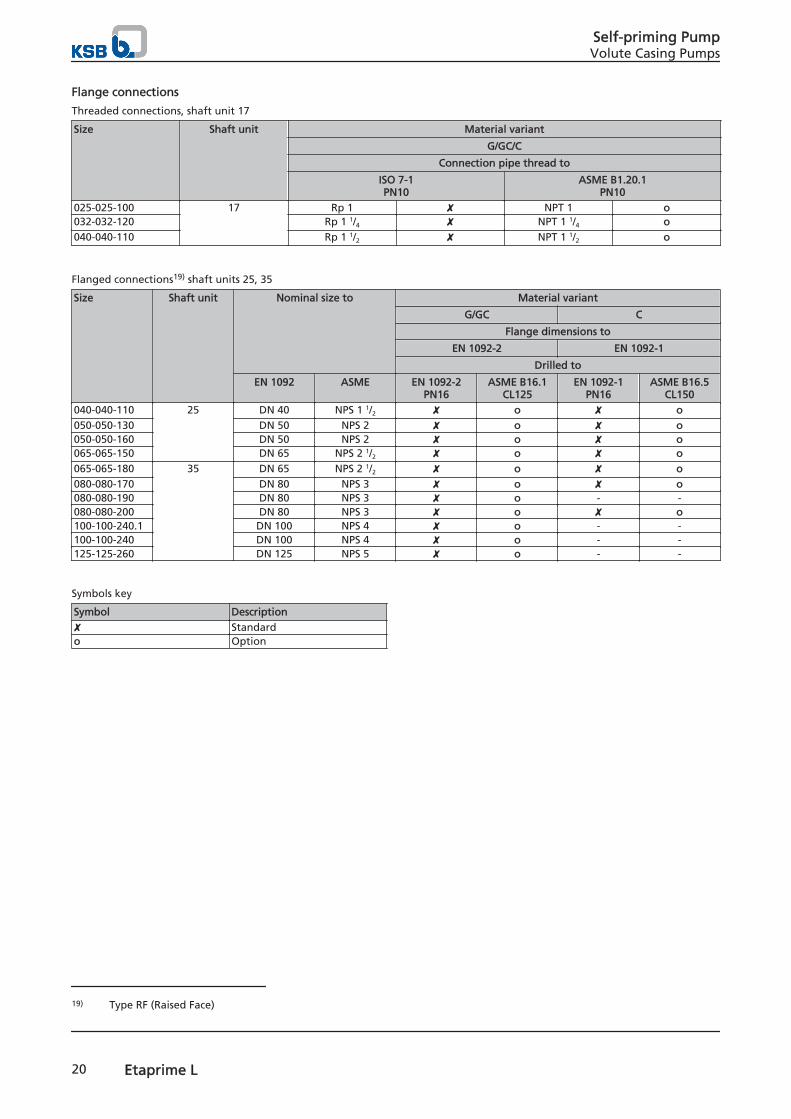
Flange connections
Threaded connections, shaft unit 17
Size Shaft unit Material variant
G/GC/C
Connection pipe thread to
ISO 7-1PN10
ASME B1.20.1PN10
025-025-100 17 Rp 1 ✘ NPT 1 o032-032-120 Rp 1 1/4 ✘ NPT 1 1/4 o040-040-110 Rp 1 1/2 ✘ NPT 1 1/2 o
Flanged connections19) shaft units 25, 35
Size Shaft unit Nominal size to Material variant
G/GC C
Flange dimensions to
EN 1092-2 EN 1092-1
Drilled to
EN 1092 ASME EN 1092-2PN16
ASME B16.1CL125
EN 1092-1PN16
ASME B16.5CL150
040-040-110 25 DN 40 NPS 1 1/2 ✘ o ✘ o050-050-130 DN 50 NPS 2 ✘ o ✘ o050-050-160 DN 50 NPS 2 ✘ o ✘ o065-065-150 DN 65 NPS 2 1/2 ✘ o ✘ o065-065-180 35 DN 65 NPS 2 1/2 ✘ o ✘ o080-080-170 DN 80 NPS 3 ✘ o ✘ o080-080-190 DN 80 NPS 3 ✘ o - -080-080-200 DN 80 NPS 3 ✘ o ✘ o100-100-240.1 DN 100 NPS 4 ✘ o - -100-100-240 DN 100 NPS 4 ✘ o - -125-125-260 DN 125 NPS 5 ✘ o - -
Symbols key
Symbol Description✘ Standardo Option
19) Type RF (Raised Face)
Self-priming PumpVolute Casing Pumps
20 Etaprime L
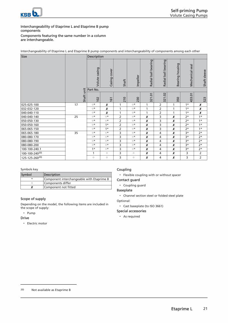
Interchangeability of Etaprime L and Etaprime B pumpcomponents
Components featuring the same number in a columnare interchangeable.
Interchangeability of Etaprime L and Etaprime B pump components and interchangeability of components among each other
Size
Shaf
t u
nit
Description
Vo
lute
cas
ing
Cas
ing
co
ver
Shaf
t
Imp
elle
r
Rad
ial b
all b
eari
ng
Rad
ial b
all b
eari
ng
Bea
rin
g h
ou
sin
g
Mec
han
ical
sea
l
Shaf
t sl
eeve
Part No.
102
161
210
230
321.
01
321.
02
350
433.
01
523
025-025-100 17 ○* ✘ 1 ○* 1 2 1 1* ✘032-032-120 ○* ✘ 1 ○* 1 2 1 1* ✘040-040-110 ○* ✘ 1 ○* 1 2 1 1* ✘040-040-140 25 ○* ○* 2 ○* ✘ 3 ✘ 2* 1*050-050-130 ○* ○* 2 ○* ✘ 3 ✘ 2* 1*050-050-160 ○* 1* 2 ○* ✘ 3 ✘ 2* 1*065-065-150 ○* 1* 2 ○* ✘ 3 ✘ 2* 1*065-065-180 35 ○* ○* 3 ○* ✘ 4 ✘ 3* 2*080-080-170 ○* ○* 3 ○* ✘ 4 ✘ 3* 2*080-080-190 ○* ○* 3 ○* ✘ 4 ✘ 3* 2*080-080-200 ○* ○* 3 ○* ✘ 4 ✘ 3* 2*100-100-240.1 1* ○* 3 ○* ✘ 4 ✘ 3* 2*100-100-24020) 1 ○ 3 ○ ✘ 4 ✘ 3 2
125-125-26020) ○ ○ 3 ○ ✘ 4 ✘ 3 2
Symbols key
Symbol Description* Component interchangeable with Etaprime B○ Components differ✘ Component not fitted
Scope of supply
Depending on the model, the following items are included inthe scope of supply:
▪ Pump
Drive
▪ Electric motor
Coupling
▪ Flexible coupling with or without spacer
Contact guard
▪ Coupling guard
Baseplate
▪ Channel section steel or folded steel plate
Optional:
▪ Cast baseplate (to ISO 3661)
Special accessories
▪ As required
20) Not available as Etaprime B
Self-priming PumpVolute Casing Pumps
Etaprime L 21

Sectional drawing and list of components
Etaprime G and C, threaded connection, with bearing housing (SU 17)
Model with single mechanical seal
[Supplied in packaging units only
List of components
Part No. Description102 Volute casing210 Shaft230 Impeller321.01/.02 Radial ball bearing350 Bearing housing411.01/.03 Joint ring412.35 O-ring433 Mechanical seal504 Spacer ring507.01/.02 Thrower550.02/.03/.04 Disc902.01 Stud903.01/.03/.06/.08 Screw plug920.01/.95 Nut932.02 Circlip940.01/.02 Key Auxiliary connections:6 B Fluid drain6 D Fluid priming and venting
Self-priming PumpVolute Casing Pumps
22 Etaprime L

Model with double mechanical seal in tandem arrangement(SU 17)
List of components
Part number Description433.01/.02 Mechanical seal473 Primary ring carrier550.02/.04 Disc720.13/.14 Barrel nipple916.97 Plug Auxiliary connections:24A Quench liquid outlet24E Quench liquid inlet
Self-priming PumpVolute Casing Pumps
Etaprime L 23

Etaprime G and C, flanged connection, with bearing bracket/grease lubrication (SU 25 and SU 35)
Model with single mechanical seal
a) b) c)
a) Clamped casing cover, b) impeller fastening elements for shaft unit 25, c) position of forcing screws
Self-priming PumpVolute Casing Pumps
24 Etaprime L

List of components
Part number Description Part number Description102 Volute casing 550.9521) Disc161 Casing cover 554.98 Lock washer164.01 Inspection cover 81-92.01/.02 Cover plate183 Support foot 901.04/.30/.31/.98 Hexagon head bolt210 Shaft 902.01/.15/.17/.18/.19 Stud230 Impeller 903.01/.03 Screw plug321.01/.02 Radial ball bearing 914.02 Pan head screw330 Bearing bracket 920.01/.05/.15/.17/.18/.19/.95 Nut360.01/.02 Bearing cover 930.95 Safety device400.75 Gasket 932.01/.02 Circlip411.01/.03/.77/.78 Joint ring 940.01/.02 Key412.35/.65 O-ring 433 Mechanical seal 523 Shaft sleeve Auxiliary connections:525 22) Spacer sleeve 6B Fluid drain550.02/.04/.17/.74 Disc 6D Fluid priming and venting
Model with double mechanical seal in tandem arrangement(SU 25/35)
List of components
Part number Description161 Casing cover400.75 Gasket412.15 O-ring411.13/.14 Joint ring433.01/.02 Mechanical seal471 Seal cover509 Intermediate ring523 Shaft sleeve52524) Spacer sleeve562.25 Parallel pin720.13/.14 Fitting902.02 Stud920.02 Hexagon nut Auxiliary connections:
21) For SU 25 only; shaft unit see data sheet.22) For SU 35 only; shaft unit see data sheet.
Self-priming PumpVolute Casing Pumps
Etaprime L 25

Part number Description24A Quench liquid outlet24E Quench liquid inlet
Model with double mechanical seal in back-to-backarrangement (SU 25/35)
List of components
Part No. Description161 Casing cover400.1523)/.75 Gasket411.13/.14 Joint ring433.01/.02 Mechanical seal471 Seal cover523 Shaft sleeve52524) Spacer sleeve720.13/.14 Fitting902.02 Stud920.02 Hexagon nut932.05 Circlip Auxiliary connections:10A Barrier fluid outlet10E Barrier fluid inlet
23) For shaft unit 25: joint ring 411.15 (shaft unit see data sheet)24) For SU 35 only; shaft unit see data sheet.
Self-priming PumpVolute Casing Pumps
26 Etaprime L

Etaprime G and C, flanged connection, with bearingbracket/oil lubrication (SU 25 and SU 35)
Design of pump and mechanical seal as described in (⇨ Page24) .Difference: oil-lubricated bearing bracket instead of grease-lubricated bearing bracket.
Model with oil lubrication and constant level oiler
[Supplied in packaging units only
List of components25)
Part No. Description Part No. Description183 Support foot 672 Vent210 Shaft 731.21 Pipe union330 Bearing bracket 901.01/.02/.04/.31 Hexagon head bolt321.01/.02 Deep groove ball bearing 903.46 Screw plug360.01/.02 Bearing cover 920.95 Hexagon nut400.01/.02 Gasket 930.95 Spring washer411.46 Joint ring 940.01/.02/.09 26) Key421.01/.02 Lip seal Connections:507.01 Thrower 8B Leakage drain550.95 27) Disc 13B Oil drain638 Constant level oiler 13D Oil filling and venting
25) Some individual components might not be applicable, depending on the size and shaft material.26) For shaft units 55 and 60 only27) For shaft unit 25 only
Self-priming PumpVolute Casing Pumps
Etaprime L 27

Detailed designation
Designation example
Position
1 2 3 4 5 6 7 8 9 10 11 12 13 14 15 16 17 18 19 20 21 22 23 24 25 26 27 28 29 30 31 32
E T P L 0 8 0 - 0 8 0 - 2 0 0 G C X I 1 0 D 3 0 1 8 5 2 B
See name plate and data sheet See data sheet
Designation key
Position Code Description1-4 Pump type
ETPL Etaprime with bearing bracket
5-16 Size 080 Nominal suction nozzle diameter [mm]
080 Nominal discharge nozzle diameter [mm]200 Nominal impeller diameter [mm]
17 Pump casing material G Cast iron
C Stainless steel18 Impeller material if different from casing material
G Cast ironC Stainless steel
19 Special design -28) Standard
X Special design20 Seal options
I Single mechanical sealD Double mechanical seal in back-to-back arrangementT Double mechanical seal in tandem arrangement
21-22 Seal code 01 Q1Q1VGG
08 AQ1VGG29)
09 U3U3VGG10 Q1Q1X4GG11 BQ1EGG
23 Scope of supply A Pump only (Fig. 0)
B Pump, baseplateC Pump, baseplate, coupling, coupling guardD Pump, baseplate, coupling, coupling guard, motor
24 Shaft unit 1 Shaft unit 17
2 Shaft unit 253 Shaft unit 35
25-28 Motor rating 0011 1,1 kW
0075 7,5 kW0185 18,5 kW
29 Number of poles 2 2 poles
4 4 poles30-31 Explosion protection
-28) Without explosion-proof motorex Explosion-proof motor
32 Product generation B Product generation Global Etaprime
28) Blank29) BQVGG for shaft unit 17
Self-priming PumpVolute Casing Pumps
28 Etaprime L


2753
.51/
01-EN
17.1
2.20
15
KSB ITUR Spain, S.A.Camino de Urteta, s/n • 20800 ZARAUTZ (Gipuzkoa) SPAINTel. +34 943 899 899 • Fax +34 943 130 710www.ksb.com
Top Related