
WINA COLOR TD1.5(A4)-ENG - YUDO Mobile...
10
)NQDCN PGVYQTM www.yudo.com Any question? Access to http://qna.yudo.com Portugal Korea Tokyo Dongguan Taiwan Hongkong Qingdao China India Thailand Singapore Indonesia Vietnam France UK Brazil Romania Suzhou Bangladesh Spain Italy Malaysia Australia South Africa New Zealand Israel Egypt Iran Netherlands Germany Czech Finland Peru Chile Colombia Argentina Philippines Headquarters Plant Subsidiary Sales office Agency Slovakia Poland Nagoya Japan Ohio Kunshan Weihai U S A Turkey Syria Mexico Russia 䯝 We reserve the right to change specifications without notice. Ver. 1.5 WINA COLOR TD (2012. Jun) Premium nozzle series WINA COLOR
Transcript of WINA COLOR TD1.5(A4)-ENG - YUDO Mobile...
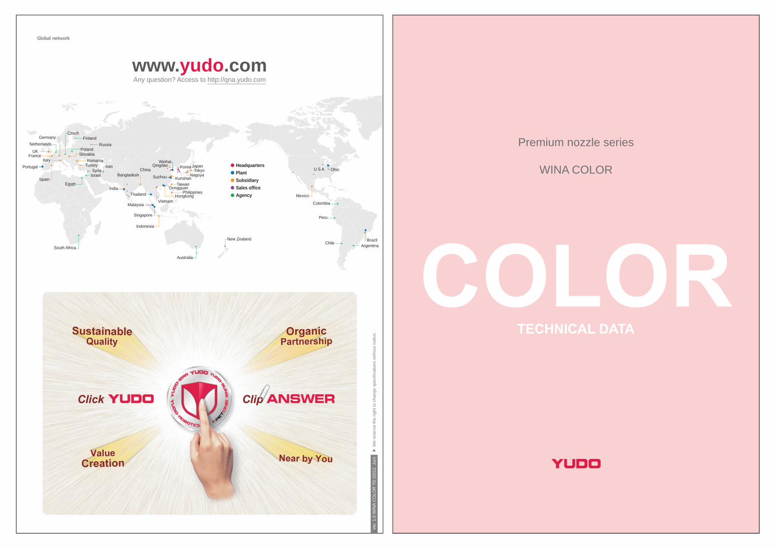
www.yudo.comAny question? Access to http://qna.yudo.com
Portugal KoreaTokyo
DongguanTaiwan
Hongkong
QingdaoChina
IndiaThailand
Singapore
Indonesia
Vietnam
FranceUK
Brazil
Romania
SuzhouBangladeshSpain
Italy
Malaysia
Australia
South Africa
New Zealand
Israel
Egypt
Iran
NetherlandsGermany
CzechFinland
Peru
Chile
Colombia
Argentina
Philippines
HeadquartersPlantSubsidiarySales officeAgency
SlovakiaPoland
Nagoya
JapanOhio
Kunshan
Weihai
U S ATurkey
Syria
Mexico
Russia
We
rese
rve
the
right
to c
hang
e sp
ecifi
catio
ns w
ithou
t not
ice.
Ver.
1.5
WIN
A C
OLO
R T
D (2
012.
Jun
)
Premium nozzle series
WINA COLOR

Packaging
General
Glass fiber(additive)
Enpla
Super
Resin
ItemHA Automobile Mobile Precision
MICRO
SUPLA
ENPLA
TIMOCOLOR
Packaging
General
Glass fiber(additive)
Enpla
Super
Resin
ItemHA Automobile Mobile Precision
YUENMASS
BALA
WINA concept
Existing YUDO product focused on commodity resin application. With increase in types of resin, requirement for special and optimizes hot runner system is necessary.
With WINA series, YUDO incorporated the best-in-class nozzle series to cater for specific resin application. There are seven series of nozzle ranging from general purpose to highly specialized super engineering plastic application.
COLOR
ENPLA
SUPLA
TIMO
CLEAR
MICRO
BIGMO
Premium hot runner solution - WINA series
The best solution for color changing mold
Hot runner for engineering plastic
Ultimate solution for super engineering plastic
Transparent application
Precise & long nozzle for reverse mold
Micro pitch valve gate for multi cavity mold
Multi-purpose system for medium & large mold

What is WINA COLOR?WINA COLOR is optimum solution for color change application.
Application COLOR is suitable for demanding color change application such as home appliance and packaging products. The home appliance world leading companies, Samsung Electronics and LG specifies COLOR on all (over 1000/year) mold development project.
Features of WINA COLOR The diagonal structure of nozzle's melting channel minimizes the resistance of resin passing through the pin guide bush. The melting channel structure of WINA COLOR not only reduce the shear stress, but also get rid of possible the dead spot in the channel.
WINA COLOR nozzle is machined in seamless one piece. One-body type of tip and nozzle eliminates potential plastic leakage between components and it's robustness provides less dimensional variation caused by high injection pressure and thermal expansion.
WINA COLOR nozzle heater newly developed provides accuracy of less than 5% variation within the length of the nozzle. A patent pending 'Insulation flange bush' without additional heating minimizes the heat conductivity and meet the required temperature. As a result, it will reduce the resistance of melting channel and result in a quick color change. An additional processes, Super horning and Ultra-sonic cleaning, improve the channel surface as the mirror surface level. Thus eliminating dead spot and reducing shear heat for optimum molding process. WINA COLOR includes various enhanced design & construction features to become the best-in-class hot runner system for color change application.
Application product : Packaging, Home appliance, Mobile phone etc, Variable color mold.Resin : PP, PE, PS, ABS, PMMA, PC etc.
INDEXNozzle data
COLOR application note / 01 / Terminology of COLOR system / 02 / Specification of COLOR system / 03 /Model number of COLOR nozzle / 04 / Long size COLOR nozzle / 05 /
Cylinder data
Pneumatic cylinder specification of COLOR / 06 / Hydraulic cylinder specification of COLOR / 07 /Pin specification of COLOR / 08 / Section of mold machining in COLOR / 09 /Gate area machining of COLOR / 10 / Cylinder area machining of COLOR / 11 / Flange area machining of COLOR / 13 /
Option
Gate bush of COLOR / 14 /
WINA COLOR nozzle

COLOR application noteCOLOR application noteSize of nozzles
Minimum gate pitch by nozzle type
Material compatibility
Unit : gram
Unit : mm
Unit : mm
: Possible: Good : Contact YUDO : Not recommended
Injection volume varies to the resin used, thickness of the product, injection speed and gate diameter.The following figures are the reference for helping to understand the various type of gate system.Please contact YUDO representative or agency for an actual application.
Size
32
42
Manifold
Channel dia.(mm)
Channel dia.(mm)
Valve pin dia.(mm)
Dia.(mm)
Area(mm2)
Area(mm2)
Nozzle Gate
12
15
4 5150822
113
177
9
12 6 85
18 10 176
1.2 / 1.5 / 2.0 / 2.5
3.0 / 3.5 / 4.0 / 4.5
5.0 / 6.0 / 7.0 / 8.0
223242
SizeViscosity Product thickness Materials
High(Low mI)
Low(High mI)
Thin( 2mm )
Thick(2mm )Medium Engineering General
~70~350350~
~120~600600~
~240~10001000~
~120~100~600
~240~1000~1000
~70~350350~
~120~600600~
Gate type
Gatingmethod Amorphous materials
VV
Additives
Flameretardants
Glassfiber filled
Stabilizerfilled
ColorchangeABS PC PMMA
(Acryl) PPO PS PUR PVC SAN PA PBT PE PET POM(Acetal) PP PPS LCP PEEK
Crystalline materials
Injection volume by nozzle size
WINA COLOR
1
Cylinder minimum pitch
ELS- rectangle
ELS- parallel
CPS- square (50, 70, 90)
A
B A
BB
A
Nozzle size
F
Nozzletype Type Square(A) Rectangle(A,B) Parallel(A,B) Center to gate(a) Gate to gate(b)
Minimum cylinder pitch Minimum nozzle pitch
COLOR 22
COLOR 32
COLOR 42
50
66
78
ValveELS 50CPS 50CPS 50CPS 70CPS 70CPS 90
-59 / 5959 / 5979 / 7979 / 7999 / 99
35 / 99-----
50 / 81-----
455560707080
525968798099
Valve
Valve
Minimum gate pitch
a
b
Nozzleflange bush
size( F)
Part by name
Terminology of COLOR system
WINA COLOR
2
Manifold unit Nozzle locator Thermocouple (Pin) Tube heater Socket head cap bolt C.P.S ring Cooling pipe Manifold block Sheath heater Thermocouple (Surface) Dowel pin Dowel pad
Cylinder unit Cylinder cover Flat head cap screw Cylinder housing Piston Glyd ring O-ring Piston in Valve pin
MODU system unit Locating ring Clamping plate Spacer plate Holding plate Cavity plate Center pin Socket head cap bolt
Nozzle unit Nozzle body Seal ring Pin guide bush Nozzle lock pin Insulation flange Tube heater Thermocouple Snap ring
Connecting unit Connector (Signal) Solenoid valve Air nipple Sol manifold Silencer Connector (Power + T/C)
WINA COLOR
3
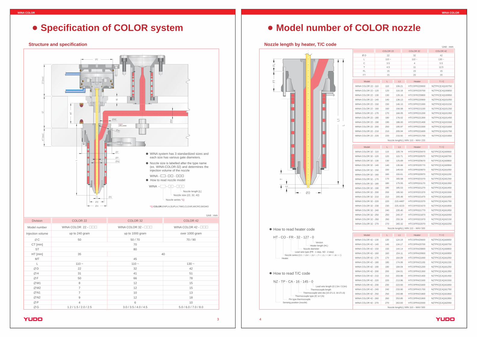
Specification of COLOR system
Unit : mm
WINA system has 3 standardized sizes and each size has various gate diameters.
Nozzle size is labelled after the type name (ex. WINA-COLOR-32) and determines the injection volume of the nozzle
How to read nozzle modelWINA - - -
Nozzle size (22, 32, 42)
Nozzle series *1)
Nozzle length [L]
*1) COLOR,ENPLA,SUPLA,TIMO,CLEAR,MICRO,BIGMO
50 / 70
110 ~324166121210
70
45
COLOR 32 COLOR 42
over 1000 gram
70 / 90
130 ~ 425178151513
up to 240 gram up to 1000 gram
50
110 ~223150877
12 1896 104
3.0 / 3.5 / 4.0 / 4.5 5.0 / 6.0 / 7.0 / 8.01.2 / 1.5 / 2.0 / 2.5
COLOR 22
WINA COLOR 42 - WINA COLOR 32 - WINA COLOR 22 - Model number
Division
Injection volume
MT
C
L
CT [min]
3580
40ST
HT [min]
DHFM1M2N1N2PG
Structure and specification
WINA - - -
C
P
N2
N1
CT [m
in]
HT
[min
]ST
M2
L
G
D
H
F
MT
15
M1
WINA COLOR
4
Model number of COLOR nozzle
How to read heater code
HT - CO - FR - 32 - 127 - 0Version
Heater length (HL)
Lead wire type (FR - 1 step, SD - 2 step)
HeaterNozzle series (COLOR,ENPLA,SUPLA,TIMO,CLEAR,MICRO,BIGMO)
Nozzle diameter
How to read T/C code
NZ - TP - CA - 16 - 145 - 0
Thermocouple lengthThermocouple wire dia (10: 1.0, 16: 1.6)
Pin type thermocoupleSensing position (nozzle)
Thermocouple type (IC or CA)
Unit : mm
WINA COLOR 42 - 130
WINA COLOR 42 - 140
WINA COLOR 42 - 150
WINA COLOR 42 - 160
WINA COLOR 42 - 170
WINA COLOR 42 - 180
WINA COLOR 42 - 190
WINA COLOR 42 - 200
WINA COLOR 42 - 210
WINA COLOR 42 - 220
WINA COLOR 42 - 230
WINA COLOR 42 - 240
WINA COLOR 42 - 250
WINA COLOR 42 - 260
210
130
140
150
160
170
180
190
200
220
230
240
250
260
270
203.98
124.19
134.17
144.14
154.11
164.09
174.06
184.04
194.01
213.96
223.93
233.90
243.88
253.85
263.83
HTCOFR420600
HTCOFR420700
HTCOFR420800
HTCOFR420900
HTCOFR421000
HTCOFR421100
HTCOFR421200
HTCOFR421300
HTCOFR421400
HTCOFR421500
HTCOFR421600
HTCOFR421700
HTCOFR421800
HTCOFR421900
HTCOFR422000
NZTPIC[CA]160650
NZTPIC[CA]160750
NZTPIC[CA]160850
NZTPIC[CA]160950
NZTPIC[CA]161050
NZTPIC[CA]161150
NZTPIC[CA]161250
NZTPIC[CA]161350
NZTPIC[CA]161450
NZTPIC[CA]161550
NZTPIC[CA]161650
NZTPIC[CA]161750
NZTPIC[CA]161850
NZTPIC[CA]161950
NZTPIC[CA]162050WINA COLOR 42 - 270
L1L Heater T / CModel
Nozzle length(L) MIN 110 ~ MAX 500
Nozzle length(L) MIN 110 ~ MAX 500
Nozzle length(L) MIN 110 ~ MAX 220
Model
110 HTCOFR320470 NZTPIC[CA]160650WINA COLOR 32 - 110
120 HTCOFR320570 NZTPIC[CA]160750WINA COLOR 32 - 120
130 HTCOFR320670 NZTPIC[CA]160850WINA COLOR 32 - 130
140 HTCOFR320770 NZTPIC[CA]160950WINA COLOR 32 - 140
150 HTCOFR320870 NZTPIC[CA]161050WINA COLOR 32 - 150
160 HTCOFR320970 NZTPIC[CA]161150WINA COLOR 32 - 160
170 HTCOFR321070 NZTPIC[CA]161250WINA COLOR 32 - 170
180 HTCOFR321170 NZTPIC[CA]161350WINA COLOR 32 - 180
190 HTCOFR321270 NZTPIC[CA]161450WINA COLOR 32 - 190
200 HTCOFR321370 NZTPIC[CA]161550WINA COLOR 32 - 200
210 HTCOFR321470 NZTPIC[CA]161650WINA COLOR 32 - 210
220 HTCOFR321570 NZTPIC[CA]161750WINA COLOR 32 - 220
106.21 HTCOFR220600 NZTPIC[CA]100750WINA COLOR 22 - 110
116.18 HTCOFR220700 NZTPIC[CA]100850WINA COLOR 22 - 120
126.16 HTCOFR220800 NZTPIC[CA]100950WINA COLOR 22 - 130
136.13 HTCOFR220900 NZTPIC[CA]101050WINA COLOR 22 - 140
146.10 HTCOFR221000 NZTPIC[CA]101150WINA COLOR 22 - 150
156.08 HTCOFR221100 NZTPIC[CA]101250WINA COLOR 22 - 160
166.05 HTCOFR221200 NZTPIC[CA]101350WINA COLOR 22 - 170
176.02 HTCOFR221300 NZTPIC[CA]101450WINA COLOR 22 - 180
186.00 HTCOFR221400 NZTPIC[CA]101550WINA COLOR 22 - 190
195.97 HTCOFR221500 NZTPIC[CA]101650WINA COLOR 22 - 200
205.94 HTCOFR221600 NZTPIC[CA]101750WINA COLOR 22 - 210
215.92 HTCOFR221700 NZTPIC[CA]101850WINA COLOR 22 - 220
110
120
130
140
150
160
170
180
190
200
210
220
230 HTCOFR321670 NZTPIC[CA]161850WINA COLOR 32 - 230
240 HTCOFR321770 NZTPIC[CA]161950WINA COLOR 32 - 240
250 HTCOFR321870 NZTPIC[CA]162050WINA COLOR 32 - 250
260 HTCOFR321970 NZTPIC[CA]162150WINA COLOR 32 - 260
270
105.74
115.71
125.69
135.66
145.63
155.61
165.58
175.55
185.53
195.50
205.48
215.4487
225.4223
235.40
245.37
255.34
265.32 HTCOFR322070 NZTPIC[CA]162250WINA COLOR 32 - 270
L1L Heater T / C
Model L1L Heater T / C
T
L
C
COLOR 22 COLOR 32 COLOR 42
FT
22
110 ~
15
15
D 32
110 ~
42
130 ~
4 5.5
11
3.5
4.5 12.5
15 15
20 20
FL
Nozzle length by heater, T/C code
Lead wire length (0:1.5m / 3:3m)
D
L
L1
FLFT
T
C

WINA COLOR
Unit : mm
L LL
Heater 1
1 step heater
2
2 step heater 3 step heater
Heater 2 Heater 3
COLOR 22
COLOR 32
COLOR 42
110 ~ 220
110 ~ 270
130 ~ 270
280 ~ 390
280 ~ 390
400 ~
- -
400 ~
1 1 2 1 3
Long size COLOR nozzleStep heater application
5
L120
Unit : mm
R13R20
FLN
100
Long size COLOR nozzle
FLN 23.5
COLOR 32
28.5
COLOR 42
Model
WINA COLOR 32-280 280 HTCOFR320720 NZTPIC[CA]162450
WINA COLOR 32-290 290 HTCOFR320820 HTCOSD321050 NZTPIC[CA]162550
WINA COLOR 32-300 300 HTCOFR320920 NZTPIC[CA]162650
WINA COLOR 32-310 310 HTCOFR320820 NZTPIC[CA]162750
WINA COLOR 32-320 320 HTCOFR320920 NZTPIC[CA]162850
WINA COLOR 32-330 330 HTCOFR321020 NZTPIC[CA]162950
WINA COLOR 32-340 340 HTCOFR321120 NZTPIC[CA]163050
WINA COLOR 32-350 350 HTCOFR321220 NZTPIC[CA]163150
WINA COLOR 32-360 360 HTCOFR321320 NZTPIC[CA]163250
WINA COLOR 32-370 370 HTCOFR321420 NZTPIC[CA]163350
WINA COLOR 32-380 380 HTCOFR321520 NZTPIC[CA]163450
WINA COLOR 32-390 390 HTCOFR321620 NZTPIC[CA]160750 NZTPIC[CA]163550
WINA COLOR 32-400 400
HTCOSD321050
HTCOMD320570 NZTPIC[CA]162450
WINA COLOR 32-410 410 NZTPIC[CA]162550
WINA COLOR 32-420 420 NZTPIC[CA]162650
WINA COLOR 32-430 430 NZTPIC[CA]162750
WINA COLOR 32-440 440 NZTPIC[CA]162850
WINA COLOR 32-450 450 HTCOFR320720 NZTPIC[CA]162950
WINA COLOR 32-460 460 NZTPIC[CA]163050
WINA COLOR 32-470 470 NZTPIC[CA]163150
WINA COLOR 32-480 480 NZTPIC[CA]163250
WINA COLOR 32-490 490 NZTPIC[CA]163350
WINA COLOR 32-500 500 NZTPIC[CA]163450
HTCOMD320670
HTCOMD320770
HTCOMD320870
HTCOMD320970
HTCOMD321070
HTCOMD321170
HTCOMD321270
HTCOMD321370
HTCOMD321470
HTCOMD321570
T/C 2T/C 1 Heater 2L Heater 1
NZTPIC[CA]164150
NZTPIC[CA]164250
NZTPIC[CA]164350
NZTPIC[CA]164450
NZTPIC[CA]164550
HTCOSD321250 NZTPIC[CA]164650
NZTPIC[CA]164750
NZTPIC[CA]164850
NZTPIC[CA]164950
NZTPIC[CA]165050
NZTPIC[CA]165150
T/C 3Heater 3
WINA COLOR 42-280 280 HTCOFR420650HTCOSD421050
NZTPIC[CA]162650
WINA COLOR 42-290 290 HTCOFR420750 NZTPIC[CA]162750
WINA COLOR 42-300 300 HTCOFR420650 NZTPIC[CA]162850
WINA COLOR 42-310 310 HTCOFR420750 NZTPIC[CA]162950
WINA COLOR 42-320 320 HTCOFR420850 NZTPIC[CA]163050
WINA COLOR 42-330 330 HTCOFR420950 NZTPIC[CA]163150
WINA COLOR 42-340 340 HTCOFR421050HTCOSD421250
NZTPIC[CA]163250
WINA COLOR 42-350 350 HTCOFR421150 NZTPIC[CA]163350
WINA COLOR 42-360 360 HTCOFR421250 NZTPIC[CA]163450
WINA COLOR 42-370 370 HTCOFR421350 NZTPIC[CA]163550
WINA COLOR 42-380 380 HTCOFR421450 NZTPIC[CA]163650
WINA COLOR 42-390 390 HTCOFR421550 NZTPIC[CA]160750 NZTPIC[CA]163750
WINA COLOR 42-400 400HTCOFR320650
HTCOMD320800 NZTPIC[CA]162750
WINA COLOR 42-410 410 HTCOMD320900 NZTPIC[CA]162850
WINA COLOR 42-420 420
HTCOFR320950
HTCOMD320700 NZTPIC[CA]162950
WINA COLOR 42-430 430 HTCOMD320800 NZTPIC[CA]163050
WINA COLOR 42-440 440 HTCOMD320900 NZTPIC[CA]163150
WINA COLOR 42-450 450 HTCOMD321000 NZTPIC[CA]163250
WINA COLOR 42-460 460 HTCOMD321100 NZTPIC[CA]163350
WINA COLOR 42-470 470 HTCOMD321200 NZTPIC[CA]163450
WINA COLOR 42-480 480 HTCOMD321300 NZTPIC[CA]163550
WINA COLOR 42-490 490 HTCOMD321400 NZTPIC[CA]163650
WINA COLOR 42-500 500 HTCOMD321500 NZTPIC[CA]163750
Model T/C 2T/C 1 Heater 2
NZTPIC[CA]164150
NZTPIC[CA]164250
NZTPIC[CA]164350
NZTPIC[CA]164450
NZTPIC[CA]164550
HTCOSD321050 NZTPIC[CA]164650
NZTPIC[CA]164750
NZTPIC[CA]164850
NZTPIC[CA]164950
NZTPIC[CA]165050
T/C 3Heater 3L Heater 1
WINA COLOR
- Output power must be the same as the voltage for solenoid valve.- Relay must be installed between injection machine and solenoid valve for valve gate hot runner system in case of using AC 220V.
- Solenoid valve for valve gate hot runner system (2-Position single)
CPS - 50 - 04
Valve cylinder type (CPS, ELS)
Valve pin diameter (04,06,10)
Cylinder size ( C : 50,70,90)
Pneumatic solenoid valve input voltage : DC 24V or AC220(YUDO STD)
Signal
Injection machine
- AC 220V
AC 220V
DC 24V
Solenoid valve magnetic
Solenoid valve
Air compressor
Relay
R1
R1 - A1
R T Input power(220V)
R1 - A2
Down strokeCylinder
Up stroke
R1 R2P
B A
CPS ELS
Output power (AC 220V)
Pneumatic circuit
3 ACRRAV352220 ACRRAV261300ACRRAV352280 ACRRAV533360
2 ACRGSO440500 ACRGSO460500ACRGSO440700 ACRGSO440900
1 Cover ACRRAV261350 ACRRAV352310 ACRRAV352370 ACRRAV261350
PistonUpper side
4 ACRRAV352231 ACRRAV352231ACRRAV352301 ACRRAV352361Lower side
5 ACRRAV261350
ACRRAV261160 ACRRAV261200 ACRRAV261200
Bottom
6 -
ACRRAV261360 ACRRAV352320 ACRRAV352380
Housing
NO. Position CPS50 GP code CPS70 GP code CPS90 GP code ELS50 GP code
Cylinder model Valve pin Nozzle model
CPS5004
ELS5004
CPS5006
CPS7006
CPS7010
CPS9010
COLOR 22
COLOR 22
COLOR 32
COLOR 32
COLOR 42
COLOR 42
4
4
6
6
10
10
Pneumatic cylinder specification of COLORPneumatic cylinder O-ring code name
Pneumatic cylinder by valve pin size
6
How to read pneumatic cylinder model
Unit : mm

WINA COLOR
Unit : mm
- Output power must be the same as the voltage for solenoid valve.- Relay must be installed between Injection machine and solenoid valve for valve gate hot runner system in case of using AC 220V.- Sequence controller for hydraulic solenoid valve has fixed voltage on manufacturing and can't be changed after the setting.
Solenoid valve for valve gate hot runner system (2-Position single)
- Hydraulic pressure into the cylinder can be controlled by a relief valve. (Recommendable pressure : 30 bar)
Hydraulic solenoid valve input voltage :DC 24V or AC220 (YUDO STD)
Down stroke
Up strokeB
B
P T
A
Solenoid valve
Cylinder
VCH 70 S is cylinder with piston position signal.
Signal
Injection machine
- AC 220V
AC 220V
DC 24V
Solenoid valve magneticRelay
R1
R1 - A1
R T Input power(220V)
R1 - A2
Output power (AC 220V)
Hydraulic cylinder O-ring code name
Hydraulic circuit
Hydraulic cylinder specification of COLOR
1 2 3 4 5 6
7
8
9
10
11
1213
14
7
Hydraulic cylinder by valve pin sizeCylinder model Valve pin
6
6
10
10
COLOR 32
COLOR 32
COLOR 42
COLOR 42
1
2
6
3
4
5
7
9
10
11
12
13
14
NO.
8
VCH 70 GH O-ring code
ACQRAR042200
ACRBU3200350
ACRRAV352250
ACROBU352300
ACROBU352140
ACROBU352250
ACRRAV352300
ACROBU352290
ACRRAV352290
ACRBU4900382
ACQRAR043250
ACRBU3200200
ACQRAR042110
ACRRAV352140
Nozzle model
VCH 70 06
VCH 70 06 S
VCH 70 10
VCH 70 10 S
WINA COLOR
Unit : mm
L2L3
R0.1
60
Gate
LL1
H
D
15
Straight type valve pin(VPS type)
How to calculate the length of valve pin
Pin specification of COLOR
8
Nozzle model
COLOR 22
COLOR 42
COLOR 32
1.2 / 1.5 / 2.0 / 2.5
5.0 / 6.0 / 7.0 / 8.0
3.0 / 3.5 / 4.0 / 4.5 6 9 4 3 5
4 7 4 2 4.5
10 15 6 4 6.5
L1 L3L2Gate HD
How to calculate the length of valve pin
- Cavity plate thickness + Holding plate thickness + Spacer plate thickness + Clamping plate thickness + Allowance in valve pin length 0.5mm + Pin protrusion 0.5mm - A - Heat expansion
- In case of hydraulic cylinder, no allowance in valve pin length will be added. CPS 50
CPS 70
CPS 90
ELS 50
VCH 78
28.5
34
34
31.3
46
52
52.5
47
41.5
ACylinder standard
AD pistonGeneral cylinder
A
A
General cylinder AD piston Hydraulic cylinder
A

WINA COLOR
9
Flange area
Gate area
Cylinder area
MODU (Hot half)
TypeMold area Cylinder Flange
Customer
YUDO
Gate
CustomerYUDO
Customer CustomerHRS (M/F + Nozzle)
Section of mold machining in COLORSection area
The core plate needs to be partially heat treated (HrC 50~52) to prevent from abrasion.
WINA COLOR
10
LVF gate
LVA gate
* T = H6 - H5
* T = H6 - H5
Gate area machining of COLORUnit : mm
Unit : mm
H1
H2
H3
H4 H5
0.02
+ -
0.02
+ -
G
D3D2D1
+0.015
+0.0
60
60
Gate bush machining
Gate area machining
1
3.0 / 3.5 / 4.0 / 4.5
14.16
32
47
4
14.5
17.5
19
0.5
1.2 / 1.5 / 2.0 / 2.5
11.96
22
37
3.5
7.5
10
12
COLOR 32
2
18
40
58
64
8.61
10.51
12
35
2
16
2
15
28
48
54
5.91
7.81
9
28
2
12
COLOR 32
COLOR 22
COLOR 22
G
D1
D2
D3
H1
H3
H4
H5
H2
G
D1
D2
D3
H1
H2
H3
H4
H5
R1
FH
1
5.0 / 6.0 / 7.0 / 8.0
19.7
42
57
5.5
17.5
20.5
22
COLOR 42
2
25
48
68
74
8.91
14.5
16
45
6040H6 80
2.5
20
COLOR 42
2
18
40
58
64
8.61
10.51
12
35
2
2
15
28
48
54
5.91
7.81
9
28
2
COLOR 32COLOR 22
G
D1
D2
D3
H1
H2
H3
H4
H5
R1
2
25
48
68
74
8.91
14.5
16
45
6040H6 80
2.5
COLOR 42
R1
H1
H2 H3
H5
0.01
+ -H
6
H4
T
FH
G
D3D2
D1+0.05 0
+0.05 0
+0.1 0
+0.015 0
20
118
118
0 -0.0
2T
0 -0.0
2
R1
H1
H2 H3
H5
0.01
+ -H
6
H4
G
D3D2
D1+0.05 0
+0.05 0
+0.1 0
+0.015 0
20
118
118
WINA COLOR
11
Clamping plate T
CT(min)
CPS 50 CPS 70 CPS 90
Unit : mm
120120
120
P.C
.D
P.C.D
3-M6 TAP DP15
R4
R3R2R1
60T 70T 75T
3-M6 TAP DP15
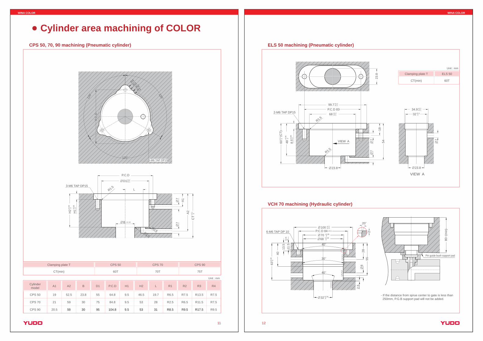
CPS 50, 70, 90 machining (Pneumatic cylinder)
7
CT
+0.1
0
7
A1
A2
R0.5R1.5
R1.5
B 0.10
D1
L
+0.0
5 0+0
.05
0
+0.2+0.1
H1
H2
Cylinder area machining of COLOR
Cylindermodel D1 P.C.D H1 H2 R1 R2 R3 R4B L
CPS 50
CPS 70
A1 A2
55 64.8 9.5 46.5 R6.5 R7.5 R13.5 R7.523.8 19.719 52.5
75 84.8 9.5 53 R2.5 R6.5 R11.5 R7.530 2821 59
95 104.8 9.5 53 R8.5 R9.5 R17.5 R9.530 3120.5 59 95 104.8 9.5 53 R8.5 R9.5 R17.530 3159CPS 90
WINA COLOR
12
- If the distance from sprue center to gate is less than 250mm, P.G.B support pad will not be added.
Unit : mm
Clamping plate T
CT(min)
ELS 50
60T
VIEW A
VIEW A
99.7+0.2+0.1
68 +0.2+0.1
(CT)
60+0
.1 0
48+0
.05
0
8.5+0
.05
0
P.C.D 832-M6 TAP DP15
23.8
77 7
5418
23.8
23.8
ELS 50 machining (Pneumatic cylinder)
VCH 70 machining (Hydraulic cylinder)
R1.5
R1.5
34.9+0.2+0.1
32+0.1 0
6-M6 TAP DP 10
13.5
11.5
40
63+0
.05
0
+0.0
50
32+0.050
40
30
40
20
828
2.5
552P.C.D 84 0.1
100 +0.2+0.1
70 +0.050
68 +0.050 80
~(m
in)
Pin guide bush support pad

WINA COLOR
13
Unit : mm
Unit : mm
Lead wire slot
Holding plate (Top side)
Lead wire slot is machined on bottom side
16
Holding plate (Bottom side)
DP62
C2
W+4W
16
R10
28
Lead wire slot
H2
H3
DP
2
3
H1
Hol
ding
pla
te(H
T)
100
DP
DP
1
45
D1
C1C1C1
D2D3
+0.02 0.00 0
.00
- 0.0
2
Flange area machining of COLOR
The dimension (H2 / H3) is changeable according to the mold thickness.
Nozzle model
COLOR 22
COLOR 32
COLOR 42
9
6
6
3
3
3
6
6
7
-
-
-
10
10
10
51
68
80
50
66
78
40
51
63
D1 D2 D3 DP DP2 H1 H2 H3 DP1
HT - H3 + H1
W
16
26
46
10
10
20
15
15
DP
1
1 ~ 2
5 ~ 6
9 ~ 12
3 ~ 4
5 ~ 8
Zone Q'ty
20
Flange area machining
WINA COLOR
14
WINA COLOR system has 1-type of gate method basically. The below pictures show gate bush options which are subjected to be applied at customer request.
Gate bush type
S - type
L - type
F - type
S - type is simply designed to protect core and easy to apply.
L - type is manufactured by adding the extension ring to the S-type or F-type gate bush and it can be adjusted to the height of mold core.
F - type is easy to control the temperature of bush by using cool or hot water.
Gate bush of COLOR (Option)
Cooling line