Software Requirements. 2 n Descriptions and specifications of a system.
72
Software Requirements
-
Upload
ferdinand-farmer -
Category
Documents
-
view
233 -
download
11
Transcript of Software Requirements. 2 n Descriptions and specifications of a system.

Software RequirementsSoftware Requirements
2
Software RequirementsSoftware Requirements
Descriptions and specifications of a system
3
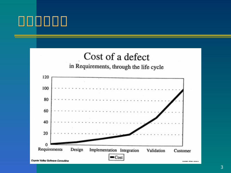
需求的重要性需求的重要性

4
对需求的要求对需求的要求
–唯一地标识需求各个语句的能力标识
– 以多种方式对需求的各个语句的分类能力 按重要性分类 按类型分类(例如功能、性能、约束、安全性) 按紧急程度分类
分类
– 跟踪每个需求语句状态的能力,以支持多个过程;例如:
– 评审状态;满足状态;鉴定状态 跟踪
其他
•以多种方式详细描述需求的能力:• 性能信息,鉴定,测试准则,根本原因,注释详细描述
• 在文档总体背景下研究需求描述的能力,即考虑与其相关的描述• 根据具体分类或背景,浏览整个需求文档并找出需求的能力• 跟踪任何单个需求语句的能力
5
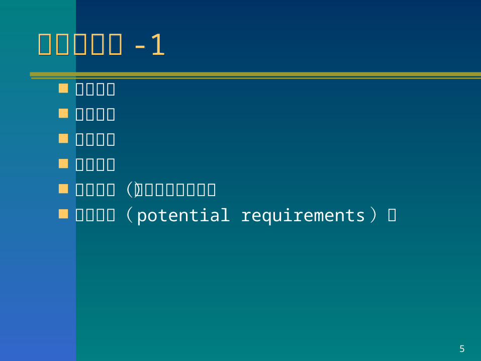
需求的分类 -1需求的分类 -1 功能需求 性能需求 界面需求 接口需求 资源需求(管理方面的需求) 潜在需求( potential requirements )等
6
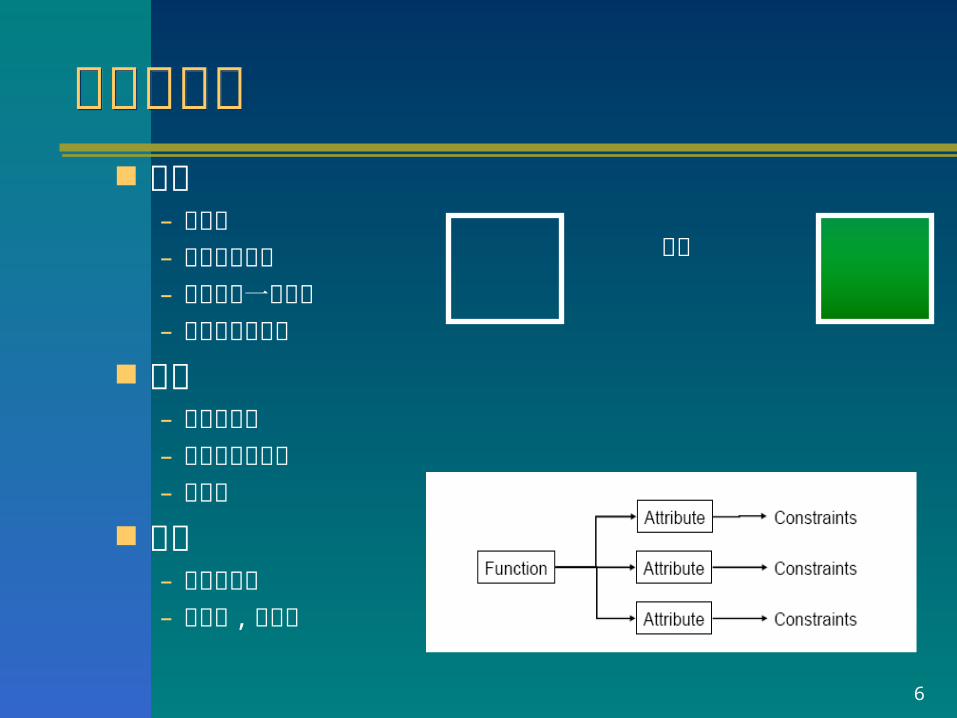
功能性需求功能性需求 功能
– 做什么– 采用动词描述– 存在也是一种功能– 可观察不可度量
属性– 功能的特征– 形容词或者副词– 可度量
约束– 属性的边界– 可度量 , 可测试
绿色

7
Non-functional requirement types
Performancerequirements
Spacerequirements
Usabilityrequirements
Efficiencyrequirements
Reliabilityrequirements
Portabilityrequirements
Interoperabilityrequirements
Ethicalrequirements
Legislativerequirements
Implementationrequirements
Standardsrequirements
Deliveryrequirements
Safetyrequirements
Privacyrequirements
Productrequirements
Organizationalrequirements
Externalrequirements
Non-functionalrequirements
8
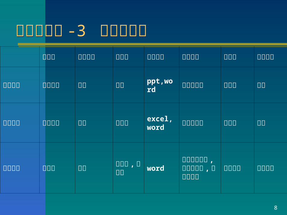
需求的分类 -3 需求的层次需求的分类 -3 需求的层次 提出者 获取方法 文档量 文档形式 评审方式 稳定性 返工影
响
目标需求 高层经理 访谈 几页 ppt,word 正规评审会 最稳定 最大
业务需求 中层经理 访谈 几十页 excel,word 正规评审会 较稳定 次之
操作需求 操作员 原型 几十页 ,上百页 word
非正式评审会 , 正规评审会 , 分多次评审
最易变化
局部影响

9
需求的分类 -4 需求的层次需求的分类 -4 需求的层次

10
需求的分类 -5 客户、产品及产品构件的需求需求的分类 -5 客户、产品及产品构件的需求
市场
最终用户
合作经理及 管理部门
客户
可操作概念及场景
产品及产品 构件的需求客户
功能分析
导出的需求
客户需求
项目相关人员

11
需求的分类 -6客户、产品及产品构件的需求需求的分类 -6客户、产品及产品构件的需求
市场
最终用户
合作经理及 管理部门
客户
客户
客户需求
项目相关人员
机械工程
软件工程
硬件工程
分配给硬件等的产品需求
其他组
产品及产品 构件的需求
12
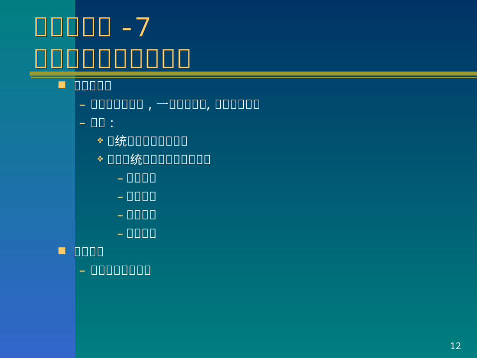
需求的分类 -7全局性需求与局部需求需求的分类 -7全局性需求与局部需求
全局性需求– 影响的面比较广 , 一旦发生变更 , 工作量比较大– 例如 :
系统中物料的编码规则 整个系统对操作员权限的限定
– 数据权限– 功能权限– 时间权限– 部门权限
局部需求– 影响的范围比较小

13
需求的分类 -8需求的分类 -8 易见性
– 明显的– 隐藏的
迫切性– 必须的– 希望的– 装饰性的

14
Requirements Engineering
Establishes the services the customer requires from a system and the constraints under which it operates and is developed
Requirements are descriptions of the system services and constraints generated during requirements engineering
Collection ofStakeholder Needs
RequirementsSpecification
!?
!?
?!!?
RequirementsEngineering

15
需求工程的内容需求工程的内容

16
需求获取需求获取 需求获取的指导原则 ( 针对信息系统 )
– 深入浅出– 以流程为主线 , 贯串功能
需求获取的步骤– 了解概况 , 收集资料– 识别合格的提供者– 准备问题– 调查或着访谈– 总结归纳 , 准备新的问题 , 迭代
注意– 要从系统的整个生命周期过程来考虑需求

17
Requirements ReadersClient managersSystem end-usersClient engineersContractor managersSystem architects
System end-usersClient engineersSystem architectsSoftware developers
Client engineers (perhaps)System architectsSoftware developers
User requirements
System requirements
Software designspecification

18
需求分析需求分析 需求分析的思维方式
– 穷举 : 确保无遗漏– 分类 : 去除冗余的需求– 分层 : 结构化表达– 抽象 : 识别最稳定的成分
需求分析的方法– 结构化方法– OO 的方法

19
需求描述需求描述 需求描述的方面 ( 针对信息系统 ):
– 组织结构与职责分配 业务流程– 功能 : 可以采用 USE CASE 描述 界面原型– 数据 处理规则– 其他约束等 及上述 7 个方面的关系
需求描述的文档格式– PPT EXCEL– WORD ROSE
注意– 需求描述详细到什么程度 ?

20
需求验证需求验证 分层次评审 正式评审与非正式评审结合 分阶段评审 精心挑选评审员 对评审员进行培训 充分利用需求评审检查单 充分准备评审 定义评审结束的条件 做好评审后的跟踪工作 建立标准的评审流程

21
Requirements MeasuresProperty MeasureSpeed Processed transactions/second
User/Event response timeScreen refresh time
Size K BytesNumber of RAM chips
Ease of use Training timeNumber of help frames
Reliability Mean time to failureProbability of unavailabilityRate of failure occurrenceAvailability
Robustness Time to restart after failurePercentage of events causing failureProbability of data corruption on failure
Portability Percentage of target dependent statementsNumber of target systems

22
需求管理需求管理 需求的变化是永恒的 需求的变化是积少成多的 需求管理的基本原则
– 需求必须划分优先级– 需求变更的成本谁来承担 ?– 小的需求变更也要纳入正规的流程– 不同层次的需求变更流程不同– 需求变更后

23
需求开发与需求管理的关系需求开发与需求管理的关系
图 2-3

24
StakeholdersStakeholders
Use the requirements todevelop validation tests forthe system
Use the requirementsdocument to plan a bid forthe system and to plan thesystem development process
Use the requirements tounderstand what system is tobe developed
System testengineers
Managers
System engineers
Specify the requirements andread them to check that theymeet their needs. Theyspecify changes to therequirements
System customers
Use the requirements to helpunderstand the system andthe relationships between itsparts
Systemmaintenance
engineers

25
练习:需求评审练习:需求评审
目标管理系统的客户需求文档

26
Required COTS Approach
Simultaneous Definition
and Tradeoffs
Marketplace
System Context
Architecture & Design
Traditional Approach(Waterfall Development)
System Context
Architecture & Design
Implementation
How does COTS change things?How does COTS change things?
Build from Scratch Buy, Integrate, Continuously Refresh
• COTS products• NDI• standards
• Strongly influenced by products
• requirements• cost• schedule• business
processes• operational
procedures, etc.
27
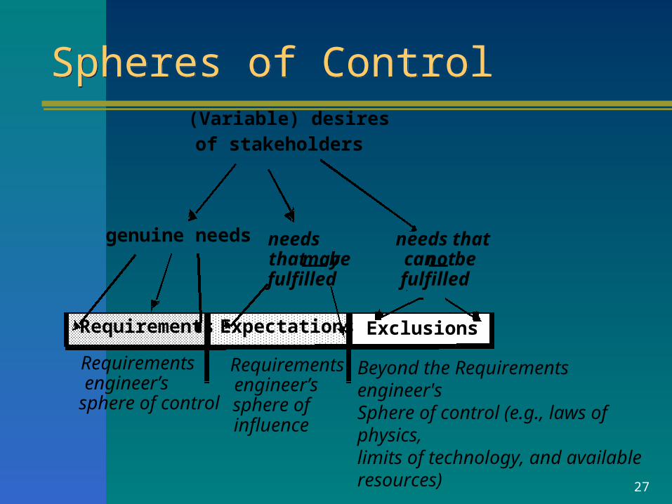
Spheres of ControlSpheres of Control
genuine needs needs
(Variable) desiresof stakeholders
Requirements
needs thatcannot befulfilled
that may befulfilled
Requirements engineer’s
Requirementsengineer’ssphere of sphere of control
Beyond the Requirements engineer's Sphere of control (e.g., laws of physics,limits of technology, and available resources)
influence
Expectations Exclusions
28
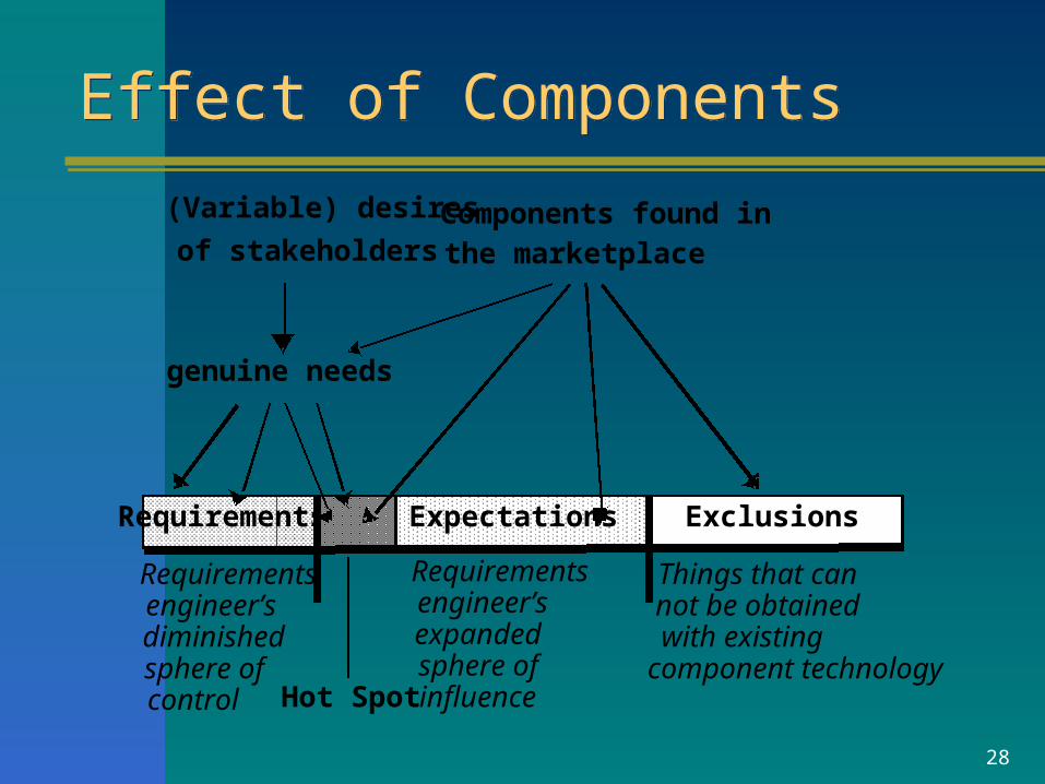
Effect of ComponentsEffect of Components
genuine needs
(Variable) desires
of stakeholders
Requirements Expectations Exclusions
Components found inthe marketplace
Requirements engineer’s diminishedsphere ofcontrol
Requirements engineer’s expandedsphere ofinfluence
Things that cannot be obtainedwith existingcomponent technology
Hot Spot
29
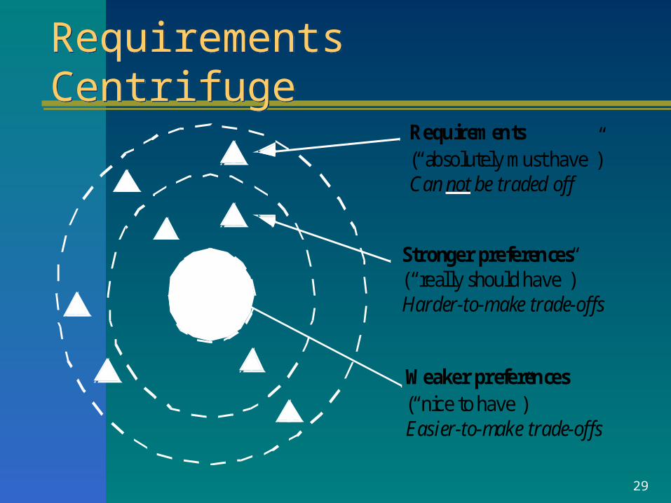
Requirements CentrifugeRequirements CentrifugeRequirements(“absolutely must have”)Can not be traded off
Stronger preferences(“really should have”)Harder-to-make trade-offs
Weaker preferences(“nice to have”)Easier-to-make trade-offs

30
Key Points 1 Requirements set out what the system should do
and define constraints on its operation and implementation
Functional requirements specify services the system should provide
Non-functional requirements constrain the system being developed or the development process
User requirements are high-level statements of what the system should do

31
Key Points 2 User requirements should be written in natural language,
tables and diagrams System requirements
– are intended to communicate the functions that the system should provide
– may be written in structured natural language PDL formal language
A software requirements document is an agreed statement of the system requirements

System ModelsSystem Models

33
System ModelsSystem Models
Abstract descriptions of systems whose requirements are being analyzed

34
Objectives
Explain why the context of a system should be modeled as part of the requirements engineering process
Describe – behavioral modeling– data modeling – object modeling
Show how CASE workbenches support system modeling

35
Topics Covered
Context models Behavioral models Data models Object models CASE workbenches

36
System Modeling System modeling
– helps the analyst understand the functionality of the system
– models are used to communicate with customers Different models present the system from different
perspectives– External - shows the system’s context or environment– Behavioral - shows the behavior of the system– Structural - shows the system or data architecture

37
Structured MethodsStructured Methods
Structured methods incorporate system modeling as an inherent part of the method
Methods define – a set of models– a process for deriving these models– rules and guidelines that apply to the models
CASE tools support system modeling as part of a structured method

38
#Method Weaknesses#Method Weaknesses
Do not model non-functional system requirements
Do not usually include information about whether a method is appropriate for a given problem
May produce too much documentation System models are sometimes too detailed
and difficult for users to understand

39
Model TypesModel Types
Data processing model showing how the data is processed at different stages
Composition model showing how entities are composed of other entities
Architectural model showing principal sub-systems Classification model showing how entities have
common characteristics Stimulus/response model showing the system’s
reaction to events

40
Context modelsContext models
Context models are used to illustrate the boundaries of a system
Social and organizational concerns may affect the decision on where to position system boundaries
Architectural models show the a system and its relationship with other systems

41
#The context of an ATM system#The context of an ATM system
Auto-tellersystem
Securitysystem
Maintenancesystem
Accountdatabase
Usagedatabase
Branchaccounting
system
Branchcountersystem
42
Process modelsProcess models
Process models show the overall process and the processes that are supported by the system
Data flow models may be used to show the processes and the flow of information from one process to another

43
Get costestimates
Acceptdelivery ofequipment
Checkdelivered
items
Validatespecification
Specifyequipmentrequired
Choosesupplier
Placeequipment
order
Installequipment
Findsuppliers
Supplierdatabase
Acceptdelivered
equipment
Equipmentdatabase
Equipmentspec.
Checkedspec.
Deliverynote
Deliverynote
Ordernotification
Installationinstructions
Installationacceptance
Equipmentdetails
Checked andsigned order form
Orderdetails +
Blank orderform
Spec. +supplier +estimate
Supplier listEquipment
spec.
Equipment Procurement Process

44
Behavioral ModelsBehavioral Models
Behavioral models are used to describe the overall behavior of a system
Two types of behavioral model are shown here– Data processing models that show how data is
processed as it moves through the system– State machine models that show the systems
response to events Both of these models are required for a
description of the system’s behavior

45
Data-processing Models
Data flow diagrams (DFDs) are used to model the system’s data processing
These show the processing steps as data flows through a system
Intrinsic part of many analysis methods Simple and intuitive notation that customers
can understand Show end-to-end processing of data

46
Order Processing DFD
Completeorder form
Orderdetails +
blankorder form
Valida teorder
Recordorder
Send tosupplier
Adjustavailablebudget
Budgetfile
Ordersfile
Completedorder form
Signedorder form
Signedorder form
Checked andsigned order
+ ordernotification
Orderamount
+ accountdetails
Signedorder form
Orderdetails

47
Data Flow DiagramsData Flow Diagrams
DFDs model the system from a functional perspective
Tracking and documenting how the data associated with a process is helpful to develop an overall understanding of the system
Data flow diagrams may also be used in showing the data exchange between a system and other systems in its environment

48
CASE Toolset DFD
Designeditor
Designcross checker
Designanalyser
Reportgenerator
Designdatabase
Code skeletongenerator
Designdatabase
Inputdesign
Validdesign
Checkeddesign
Designanalysis
Userreport
and
Referenceddesigns
Checkeddesign Output
code
49
#State Machine Models#State Machine Models
These model the behavior of the system in response to external and internal events
They show the system’s responses to stimuli so are often used for modeling real-time systems
State machine models show system states as nodes and events as arcs between these nodes. – When an event occurs, the system moves
from one state to another– State charts are an integral part of the UML

50
Microwave Oven ModelMicrowave Oven ModelFull power
Enabled
do: operateoven
Fullpower
Halfpower
Halfpower
Fullpower
Number
TimerDooropen
Doorclosed
Doorclosed
Dooropen
Start
do: set power = 600
Half powerdo: set power = 300
Set time
do: get numberexit: set time
Disabled
Operation
Timer
Cancel
Waiting
do: display time
Waiting
do: display time
do: display 'Ready'
do: display 'Waiting'

51
Microwave Oven State DescriptionMicrowave Oven State Description

52
Microwave oven stimuliMicrowave oven stimuli

53
State ChartsState Charts
Allow the decomposition of a model into sub-models (see following slide)
A brief description of the actions is included following the ‘do’ in each state
Can be complemented by tables describing the states and the stimuli
54
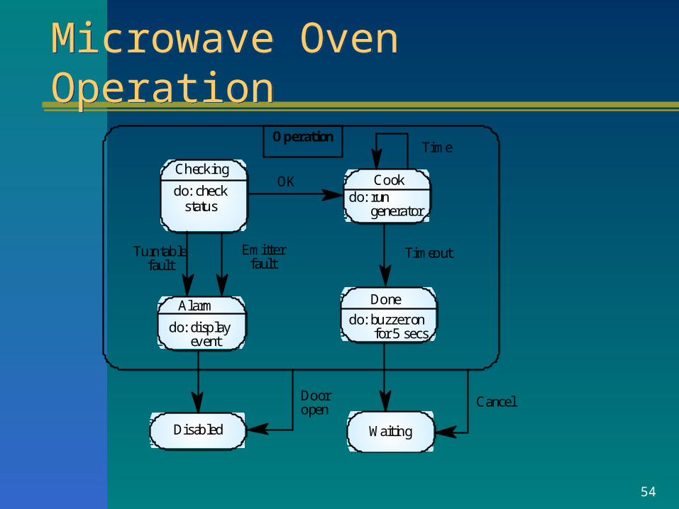
Microwave Oven OperationMicrowave Oven Operation
Cookdo: run generator
Done
do: buzzer on for 5 secs.
Waiting
Alarm
do: display event
do: checkstatus
Checking
Turntablefault
Emitterfault
Disabled
OK
Timeout
TimeOperation
Dooropen
Cancel

55
Semantic Data Models
Used to describe the logical structure of data processed by the system
Entity-relation-attribute model – entities in the system– relationships between these entities – entity attributes
Widely used in database design. – readily implemented using relational databases
No specific notation provided in the UML but objects and associations can be used

56
Software Design Semantic Model
Design
namedescriptionC-dateM-date
Link
nametype
Node
nametype
links
has-links
12
1 n
Label
nametexticon
has-labelshas-labels
1
n
1
n
has-linkshas-nodes is-a
1
n
1
n1
1

57
Data DictionariesData Dictionaries
Data dictionaries are lists of all of the names used in the system models including descriptions of – Entities– Relationships – Attributes
Advantages– Support name management and avoid duplication– Store of organizational knowledge linking analysis,
design and implementation Many CASE workbenches support data dictionaries

58
Data Dictionary EntriesData Dictionary Entries

59
Object Models
Object models describe the system in terms of object classes
An object class is an abstraction over a set of objects with common attributes and the services (operations) provided by each object
Various object models may be produced
– Inheritance
– Aggregation
– Interaction

60
Object Models
Natural ways of reflecting the real-world entities manipulated by the system
More abstract entities are more difficult to model using this approach
Object class identification is recognized as a difficult process requiring a deep understanding of the application domain
Object classes reflecting domain entities are reusable across systems

61
Inheritance Models
Organize the domain object classes into a hierarchy
Classes at the top of the hierarchy reflect the common features of all classes
Object classes inherit their attributes and services from one or more super-classes. these may then be specialized as necessary
Class hierarchy design is a difficult process if duplication in different branches is to be avoided

62
Multiple Inheritance
Rather than inheriting the attributes and services from a single parent class, a system which supports multiple inheritance allows object classes to inherit from several super-classes
Can lead to semantic conflicts where attributes/services with the same name in different super-classes have different semantics
Makes class hierarchy reorganization more complex

63
Multiple Inheritance
# Tapes
Talking book
AuthorEditionPublication dateISBN
Book
SpeakerDurationRecording date
Voice recording
64
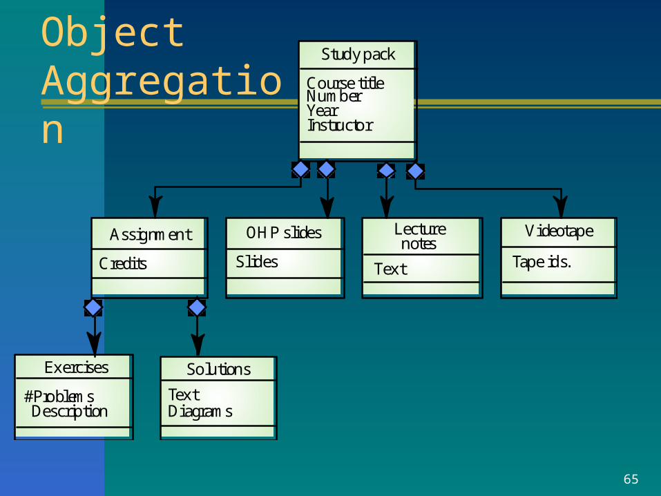
Object Aggregation
Aggregation model shows how classes which are collections are composed of other classes
Similar to the part-of relationship in semantic data models
65
Videotape
Tape ids.
Lecturenotes
Text
OHP slides
Slides
Assignment
Credits
Solutions
TextDiagrams
Exercises
#Problems Description
Course titleNumberYearInstructor
Study pack
Object Aggregation

66
Object Behavior ModelingObject Behavior Modeling
A behavioral model shows the interactions between objects to produce some particular system behavior that is specified as a use-case
Sequence diagrams (or collaboration diagrams) in the UML are used to model interaction between objects

67
Issue of Electronic ItemsIssue of Electronic Items
:Library User
Ecat:Catalog
Lookup
Issue
Display
:Library Item Lib1:NetServer
Issue licence
Accept licence
Compress
Deliver

68
CASE WorkbenchesCASE Workbenches
A coherent set of tools that is designed to support related software process activities such as analysis, design or testing
Analysis and design workbenches support system modeling during both requirements engineering and system design
These workbenches may support a specific design method or may provide support for a creating several different types of system model

69
An Analysis and Design Workbench
Centralinformationrepository
Codegenerator
Querylanguagefacilities
Structureddiagramming
tools
Datadictionary
Reportgenerationfacilities
Design, analysisand checking
tools
Formscreation
tools
Import/exportfacilities

70
Analysis Workbench ComponentsAnalysis Workbench Components
Diagram editors Model analysis and checking tools Repository and associated query language Data dictionary Report definition and generation tools Forms definition tools Import/export translators Code generation tools

71
Key Points 1
A model is an abstract system view. Complementary types of models provide different
system information– Context models show the position of a system in
its environment with other systems and processes– Data flow models may be used to model the data
processing in a system– State machine models model the system’s
behavior in response to internal or external events

72
Key Points 2
Semantic data models describe the logical structure of data which is imported to or exported by the systems
Object models describe logical system entities, their classification and aggregation
Object models describe the logical system entities and their classification and aggregation
CASE workbenches support the development of system models