Restricted for the - 首页-yeec维修网 - Powered by … · 2007-07-30 · DIAGNOSTICS. 30JUL07...
326
Confidential Restricted Information © Carestream Health, Inc., 2007 {Diagnostics}{Production}{Health Group}{ExternalAndInternal} Publication No. 8F2919 30JUL07 DIAGNOSTICS for the Kodak DryView 6800 LASER IMAGER Service Code: 1649 Important Qualified personnel must repair this equipment. H210_0800GC
-
Upload
truongcong -
Category
Documents
-
view
258 -
download
0
Transcript of Restricted for the - 首页-yeec维修网 - Powered by … · 2007-07-30 · DIAGNOSTICS. 30JUL07...
ConfidentialRestricted
Information
© Carestream Health, Inc., 2007
{Diagnostics}{Production}{Health Group}{ExternalAndInternal} Publication No. 8F291930JUL07
DIAGNOSTICSfor the
Kodak DryView 6800 LASER IMAGERService Code: 1649
ImportantQualified personnel must repair this equipment.
H210_0800GC
~DOCVIEW /Fit
~BKMK_FILE (Library) (../../library.pdf) /F
~BKMK_FILE (Manual Contents) (../contents.pdf) /F
~BKMK_FILE (Table of Contents) (8E5983.pdf) /G1241980
~DOCINFO (DIAGNOSTICSfor theKodak DryView 8900 LASER IMAGER) (8E5983 22DEC03) (Kodak Service and Support) (FrameMaker+SGML 7.0.0 MSWindows)
DIAGNOSTICS
30JUL078F2919 Page
2 of 326
PLEASE NOTE The information contained herein is based on the experience and knowledge relating to the subject matter gained by Carestream Health, Inc., prior to publication.
No patent license is granted by this information.
Carestream Health, Inc., reserves the right to change this information without notice, and makes no warranty, express or implied, with respect to this information. Carestream Health, Inc., shall not be liable for any loss or damage, including consequential or special damages, resulting from any use of this information, even if loss or damage is caused by Carestream Health, Inc., negligence or other fault.
This equipment includes parts and assemblies sensitive to damage from electrostaticdischarge. Use caution to prevent damage during all service procedures.
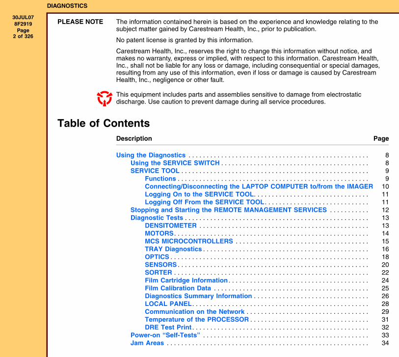
Description Page
Table of Contents
Using the Diagnostics . . . . . . . . . . . . . . . . . . . . . . . . . . . . . . . . . . . . . . . . . . . . . . . . . . 8Using the SERVICE SWITCH . . . . . . . . . . . . . . . . . . . . . . . . . . . . . . . . . . . . . . . . . 8SERVICE TOOL . . . . . . . . . . . . . . . . . . . . . . . . . . . . . . . . . . . . . . . . . . . . . . . . . . . . 9
Functions . . . . . . . . . . . . . . . . . . . . . . . . . . . . . . . . . . . . . . . . . . . . . . . . . . . . . 9Connecting/Disconnecting the LAPTOP COMPUTER to/from the IMAGER 10Logging On to the SERVICE TOOL. . . . . . . . . . . . . . . . . . . . . . . . . . . . . . . . 11Logging Off From the SERVICE TOOL . . . . . . . . . . . . . . . . . . . . . . . . . . . . . 11
Stopping and Starting the REMOTE MANAGEMENT SERVICES . . . . . . . . . . . 12Diagnostic Tests . . . . . . . . . . . . . . . . . . . . . . . . . . . . . . . . . . . . . . . . . . . . . . . . . . . 13
DENSITOMETER . . . . . . . . . . . . . . . . . . . . . . . . . . . . . . . . . . . . . . . . . . . . . . . 13MOTORS . . . . . . . . . . . . . . . . . . . . . . . . . . . . . . . . . . . . . . . . . . . . . . . . . . . . . . 14MCS MICROCONTROLLERS . . . . . . . . . . . . . . . . . . . . . . . . . . . . . . . . . . . . . 15TRAY Diagnostics . . . . . . . . . . . . . . . . . . . . . . . . . . . . . . . . . . . . . . . . . . . . . . 16OPTICS . . . . . . . . . . . . . . . . . . . . . . . . . . . . . . . . . . . . . . . . . . . . . . . . . . . . . . . 18SENSORS . . . . . . . . . . . . . . . . . . . . . . . . . . . . . . . . . . . . . . . . . . . . . . . . . . . . . 20SORTER . . . . . . . . . . . . . . . . . . . . . . . . . . . . . . . . . . . . . . . . . . . . . . . . . . . . . . 22Film Cartridge Information . . . . . . . . . . . . . . . . . . . . . . . . . . . . . . . . . . . . . . . 24Film Calibration Data . . . . . . . . . . . . . . . . . . . . . . . . . . . . . . . . . . . . . . . . . . . 25Diagnostics Summary Information . . . . . . . . . . . . . . . . . . . . . . . . . . . . . . . . 26LOCAL PANEL. . . . . . . . . . . . . . . . . . . . . . . . . . . . . . . . . . . . . . . . . . . . . . . . . 28Communication on the Network . . . . . . . . . . . . . . . . . . . . . . . . . . . . . . . . . . 29Temperature of the PROCESSOR . . . . . . . . . . . . . . . . . . . . . . . . . . . . . . . . . 31DRE Test Print . . . . . . . . . . . . . . . . . . . . . . . . . . . . . . . . . . . . . . . . . . . . . . . . . 32
Power-on “Self-Tests” . . . . . . . . . . . . . . . . . . . . . . . . . . . . . . . . . . . . . . . . . . . . . . 33Jam Areas . . . . . . . . . . . . . . . . . . . . . . . . . . . . . . . . . . . . . . . . . . . . . . . . . . . . . . . . 34
DIAGNOSTICS
30JUL078F2919 Page
3 of 326
Status Messages and Error Codes . . . . . . . . . . . . . . . . . . . . . . . . . . . . . . . . . . . . . . . . 35Overview. . . . . . . . . . . . . . . . . . . . . . . . . . . . . . . . . . . . . . . . . . . . . . . . . . . . . . . . . . 35DICOM Status Messages . . . . . . . . . . . . . . . . . . . . . . . . . . . . . . . . . . . . . . . . . . . . 35PRINTER Status Messages . . . . . . . . . . . . . . . . . . . . . . . . . . . . . . . . . . . . . . . . . . 37FILM TRAY Status Messages . . . . . . . . . . . . . . . . . . . . . . . . . . . . . . . . . . . . . . . . 40JOB MANAGER Status Messages. . . . . . . . . . . . . . . . . . . . . . . . . . . . . . . . . . . . . 41Error Codes . . . . . . . . . . . . . . . . . . . . . . . . . . . . . . . . . . . . . . . . . . . . . . . . . . . . . . . 41
Subsystems in the 6800 LASER IMAGER . . . . . . . . . . . . . . . . . . . . . . . . . . 41Error “Severity” Level. . . . . . . . . . . . . . . . . . . . . . . . . . . . . . . . . . . . . . . . . . . 43Error 01-000: General CONFIGURATION AND CONTROL SUBSYSTEM Error45Error 01-001: Maximum Number of Restarts Exceeded . . . . . . . . . . . . . . . 46Error 01-002: Error Reading Configuration Information . . . . . . . . . . . . . . . 47Error 01-004: Error Starting a Subsystem . . . . . . . . . . . . . . . . . . . . . . . . . . 48Error 01-005: Error Stopping a Subsystem . . . . . . . . . . . . . . . . . . . . . . . . . 49Error 01-007: General Subsystem Communication Error. . . . . . . . . . . . . . 50Error 01-008: All Subsystems Started . . . . . . . . . . . . . . . . . . . . . . . . . . . . . 51Error 01-009: OPERATING SYSTEM Could Not Be Shut Down. . . . . . . . . 52Error 01-010: Subsystem Terminated Abnormally . . . . . . . . . . . . . . . . . . . 53Error 04-000: General DICOM INPUT PRINT SCP SUBSYSTEM Error . . . 54Error 04-100: Limit on Number of Associations Exceeded . . . . . . . . . . . . 55Error 04-101: AE Title does not Correspond to a Recognized PRINTER. 56Error 04-110: Invalid Association Request . . . . . . . . . . . . . . . . . . . . . . . . . 57Error 04-200: DISK Full. . . . . . . . . . . . . . . . . . . . . . . . . . . . . . . . . . . . . . . . . . 58Error 04-201: Keep-Alive Message Failure . . . . . . . . . . . . . . . . . . . . . . . . . . 59Error 04-202: Connection Is Lost . . . . . . . . . . . . . . . . . . . . . . . . . . . . . . . . . 60Error 04-300: PLUT is Missing. . . . . . . . . . . . . . . . . . . . . . . . . . . . . . . . . . . . 61Error 04-301: Missing Necessary Attribute . . . . . . . . . . . . . . . . . . . . . . . . . 62Error 04-302: Invalid Attribute . . . . . . . . . . . . . . . . . . . . . . . . . . . . . . . . . . . . 63Error 05-000: Error Unknown. . . . . . . . . . . . . . . . . . . . . . . . . . . . . . . . . . . . . 64Error 05-001: Error Reading Configuration Information . . . . . . . . . . . . . . . 65Error 05-002: Study Reclamation Initiated . . . . . . . . . . . . . . . . . . . . . . . . . . 66Error 05-003: Low-Water Mark Cannot be Reached . . . . . . . . . . . . . . . . . . 67Error 05-004: Low-Water Mark Reached. . . . . . . . . . . . . . . . . . . . . . . . . . . . 68Error 05-005: Study Reclamation Shutting Down . . . . . . . . . . . . . . . . . . . . 69Error 06-000: General DELIVERY SUBSYSTEM Error. . . . . . . . . . . . . . . . . 70Error 06-001: General Start UP Error . . . . . . . . . . . . . . . . . . . . . . . . . . . . . . 71Error 06-002: Bad or Missing Configuration Data. . . . . . . . . . . . . . . . . . . . 72Error 06-101: Internal Job Processing Error . . . . . . . . . . . . . . . . . . . . . . . . 73Error 06-102: PRINTER Not Ready . . . . . . . . . . . . . . . . . . . . . . . . . . . . . . . . 74Error 06-103: Invalid Media . . . . . . . . . . . . . . . . . . . . . . . . . . . . . . . . . . . . . . 75Error 06-104: Media Not Available . . . . . . . . . . . . . . . . . . . . . . . . . . . . . . . . 76Error 06-105: Page Delivery Success . . . . . . . . . . . . . . . . . . . . . . . . . . . . . . 77
DIAGNOSTICS
30JUL078F2919 Page
4 of 326
Error 06-106: Job Delivery Success . . . . . . . . . . . . . . . . . . . . . . . . . . . . . . . 78Error 06-200: MIM Data Component Error . . . . . . . . . . . . . . . . . . . . . . . . . . 79Error 06-300: Destination Business Logic Error . . . . . . . . . . . . . . . . . . . . . 80Error 06-400: General Page Builder Error . . . . . . . . . . . . . . . . . . . . . . . . . . 81Error 06-410: Rendering Error . . . . . . . . . . . . . . . . . . . . . . . . . . . . . . . . . . . . 82Error 06-411: Bad Image Data . . . . . . . . . . . . . . . . . . . . . . . . . . . . . . . . . . . . 84Error 06-412: Abort Requested . . . . . . . . . . . . . . . . . . . . . . . . . . . . . . . . . . . 85Error 06-420: Invalid Data or Data Access Error. . . . . . . . . . . . . . . . . . . . . 86Error 06-430: Chain-Building Error . . . . . . . . . . . . . . . . . . . . . . . . . . . . . . . . 88Error 06-500: Internal PAGE DELIVERY Component Error . . . . . . . . . . . . 89Error 06-501: Media Not Loaded . . . . . . . . . . . . . . . . . . . . . . . . . . . . . . . . . . 90Error 06-502: Media Needs Calibration. . . . . . . . . . . . . . . . . . . . . . . . . . . . . 91Error 06-503: Media is Calibrating . . . . . . . . . . . . . . . . . . . . . . . . . . . . . . . . 92Error 06-504: Calibration Error . . . . . . . . . . . . . . . . . . . . . . . . . . . . . . . . . . . 93Error 06-505: Media is Empty . . . . . . . . . . . . . . . . . . . . . . . . . . . . . . . . . . . . 94Error 06-506: Jam in Media . . . . . . . . . . . . . . . . . . . . . . . . . . . . . . . . . . . . . . 95Error 06-600: General Delivery Engine Error . . . . . . . . . . . . . . . . . . . . . . . . 96Error 10-001: Internal Software Error in MIS . . . . . . . . . . . . . . . . . . . . . . . . 97Error 10-003: Image Buffer Error in MIS. . . . . . . . . . . . . . . . . . . . . . . . . . . . 98Error 10-015: Database Error in MIS. . . . . . . . . . . . . . . . . . . . . . . . . . . . . . . 99Error 10-910: No Communications with the MCS . . . . . . . . . . . . . . . . . . . . 100Error 12-075: LOCAL PANEL Error . . . . . . . . . . . . . . . . . . . . . . . . . . . . . . . . 101Error 12-080: Software Update Error . . . . . . . . . . . . . . . . . . . . . . . . . . . . . . 102Error 12-085: LOCAL PANEL Flash Error . . . . . . . . . . . . . . . . . . . . . . . . . . 103Error 13-001: SERVICE TOOL Internal Error . . . . . . . . . . . . . . . . . . . . . . . . 104Error 13-002: SERVICE TOOL Database Error. . . . . . . . . . . . . . . . . . . . . . . 105Error 20-004: USB Did Not initialize . . . . . . . . . . . . . . . . . . . . . . . . . . . . . . . 106Error 20-154: MCS HARD DRIVE Failure . . . . . . . . . . . . . . . . . . . . . . . . . . . 107Error 20-156: Incompatible Software Versions Installed . . . . . . . . . . . . . . 108Error 20-209: LASER IMAGER Opened During Self-Test . . . . . . . . . . . . . . 110Error 20-550: Preventive Maintenance Necessary . . . . . . . . . . . . . . . . . . . 112Error 20-551: PROCESSOR FILTER Maintenance Necessary . . . . . . . . . . 113Error 20-913: DRE Data Transfer Error Notification . . . . . . . . . . . . . . . . . . 114Error 20-915: DRE Data Transfer Fatal Error Detected . . . . . . . . . . . . . . . 115Error 20-917: DRE Data Transfer Timing Error Notification. . . . . . . . . . . . 117Error 20-918: DRE Data Transfer Too Slow. Fatal Timing Error Detected 118Error 20-919: DRE Image Render Not Complete . . . . . . . . . . . . . . . . . . . . . 120Error 21-116, 22-116, or 23-116: Film Pickup Failure . . . . . . . . . . . . . . . . . 122Error 21-117, 22-117, or 23-117: Film Pickup Retry . . . . . . . . . . . . . . . . . . 125Error 21-118, 22-118, or 23-118: PICKUP Did Not Go Home . . . . . . . . . . . 126Error 21-119, 22-119, or 23-119: Film Contact Failure . . . . . . . . . . . . . . . . 128Error 21-120, 22-120, or 23-120: CUPS Engaged Failure . . . . . . . . . . . . . . 131
DIAGNOSTICS
30JUL078F2919 Page
5 of 326
Error 21-125, 22-125, or 23-125: FEED ROLLER Nip Failure . . . . . . . . . . 133Error 21-126, 22-126, or 23-126: Jam at Feeder . . . . . . . . . . . . . . . . . . . . . 135Error 21-139, 22-139, or 23-139: Unable to Read or Write to RF TAG . . . 137Error 21-145, 22-145, or 23-145: Unsupported Media Type . . . . . . . . . . . . 139Error 21-146, 22-146, or 23-146: Unsupported Media Size . . . . . . . . . . . . . 141Error 21-154, 22-154, or 23-154: Supply CONTROLLER NVRAM Failure . 143Error 21-175, 22-175, or 23-175: ROLLBACK Did Not Engage CARTRIDGE 145Error 21-176, 22-176, or 23-176: FILM CARTRIDGE Did Not Open Fully . 147Error 21-177, 22-177, or 23-177: FILM CARTRIDGE Did Not Close . . . . . . 149Error 21-178, 22-178, or 23-178: ROLLBACK Did Not Leave Home . . . . . 152Error 21-179, 22-179, or 23-179: ROLLBACK Did Not Move From Open . 155Error 21-320, 22-320, or 23-320: Jam Entering the ACCUMULATOR . . . . 158Error 21-624, 22-624, or 23-624: Bad DENSITOMETER Data . . . . . . . . . . . 160Error 21-631, 22-631, or 23-631: Dmin Not Met . . . . . . . . . . . . . . . . . . . . . 162Error 21-632, 22-632, or 23-632: Dmax Not Met. . . . . . . . . . . . . . . . . . . . . . 164Error 21-922, 22-922, or 23-922: RF TAG Diagnostics Failure . . . . . . . . . . 166Error 21-931, 22-931, or 23-931: SUPPLY CONTROLLER Communications
Failure . . . . . . . . . . . . . . . . . . . . . . . . . . . . . . . . . . . . . . . . . . . . . . . . . . . . . . 168Error 21-932, 22-932, or 23-932: SUPPLY CONTROLLER Communications
Retry . . . . . . . . . . . . . . . . . . . . . . . . . . . . . . . . . . . . . . . . . . . . . . . . . . . . . . . 170Error 26-321: Jam Exiting ACCUMULATOR . . . . . . . . . . . . . . . . . . . . . . . . . 171Error 26-325: Jam Entering EXPOSURE TRANSPORT . . . . . . . . . . . . . . . . 173Error 26-326: Jam Exiting EXPOSURE TRANSPORT . . . . . . . . . . . . . . . . . 175Error 26-543: Jam Before the DENSITOMETER. . . . . . . . . . . . . . . . . . . . . . 177Error 26-544: Jam at DENSITOMETER . . . . . . . . . . . . . . . . . . . . . . . . . . . . . 179Error 27-121: ATTENUATOR MOTOR Home Error . . . . . . . . . . . . . . . . . . . 181Error 27-123: POLYGON MOTOR Error . . . . . . . . . . . . . . . . . . . . . . . . . . . . 183Error 27-154: OPTICS NVRAM Failure . . . . . . . . . . . . . . . . . . . . . . . . . . . . . 185Error 27-601: Invalid POWER MONITOR Offset . . . . . . . . . . . . . . . . . . . . . . 187Error 27-602: Invalid POWER MONITOR Range with ATTENUATOR Open 189Error 27-603: Invalid ATTENUATOR Optical Density Range . . . . . . . . . . . 191Error 27-604: Unable to Adjust LASER Dynamic Range . . . . . . . . . . . . . . 193Error 27-605: POWER MONITOR Saturation . . . . . . . . . . . . . . . . . . . . . . . . 195Error 27-606: ATTENUATOR Calibration Failed (Non-Monotonic) . . . . . . 197Error 27-607: OPTICS Exceeded Maximum LASER Power . . . . . . . . . . . . 199Error 27-608: Invalid LASER Dynamic Range . . . . . . . . . . . . . . . . . . . . . . . 201Error 27-609: OPTICS Approaching Maximum LASER Power. . . . . . . . . . 202Error 27-611: OPTICS LASER Gain Adjustment Failed . . . . . . . . . . . . . . . 203Error 27-646: Start of Page Error . . . . . . . . . . . . . . . . . . . . . . . . . . . . . . . . . 205Error 27-647: START OF PAGE SENSOR Failure . . . . . . . . . . . . . . . . . . . . 207Error 27-648: LASER Scan Correction DAC Failure . . . . . . . . . . . . . . . . . . 209Error 27-650: Exposure Timeout Error . . . . . . . . . . . . . . . . . . . . . . . . . . . . . 211
DIAGNOSTICS
30JUL078F2919 Page
6 of 326
Error 27-651: Exposure Timeout Notification . . . . . . . . . . . . . . . . . . . . . . . 213Error 27-931: OPTICS Communications Failure . . . . . . . . . . . . . . . . . . . . . 214Error 27-932: OPTICS Communications Retry. . . . . . . . . . . . . . . . . . . . . . . 216Error 28-154: PROCESSOR NVRAM Failure . . . . . . . . . . . . . . . . . . . . . . . . 217Error 28-155: Bad PROCESSOR NVRAM Parameters. . . . . . . . . . . . . . . . . 219Error 28-501: PROCESSOR RTD Short Circuit . . . . . . . . . . . . . . . . . . . . . . 221Error 28-509: PROCESSOR Did Not Complete Warm Up. . . . . . . . . . . . . . 223Error 28-551: PROCESSOR HEATER Failure . . . . . . . . . . . . . . . . . . . . . . . . 225Error 28-554: Temperature Error . . . . . . . . . . . . . . . . . . . . . . . . . . . . . . . . . . 227Error 28-931: PROCESSOR Communications Failure . . . . . . . . . . . . . . . . 229Error 28-932: PROCESSOR Communications Retry . . . . . . . . . . . . . . . . . . 231Error 29-154: DENSITOMETER NVRAM Failure . . . . . . . . . . . . . . . . . . . . . . 232Error 29-924: DENSITOMETER Failed Offset Reading Diagnostics . . . . . 234Error 29-925: DENSITOMETER Reference Reading Failed Diagnostics . . 236Error 29-926: DENSITOMETER Fiducial Failed Offset Diagnostics. . . . . . 238Error 29-927: DENSITOMETER Fiducial Failed Reference Diagnostics . . 240Error 29-931: DENSITOMETER Communications Failure . . . . . . . . . . . . . . 242Error 29-932: DENSITOMETER Communications Retry . . . . . . . . . . . . . . 244Error 29-945: DENSITOMETER Reference Reading Diagnostics Warning 245Error 29-947: DENSITOMETER Fiducial Reference Diagnostics Warning 246Error 30-154: SORTER NVRAM Failure . . . . . . . . . . . . . . . . . . . . . . . . . . . . 247Error 30-931: SORTER Communications Failure . . . . . . . . . . . . . . . . . . . . 249Error 30-932: SORTER Communications Retry . . . . . . . . . . . . . . . . . . . . . 251Error 30-935: SORTER DIVERTER #1 Failure . . . . . . . . . . . . . . . . . . . . . . . 252Error 30-936: SORTER DIVERTER #2 Failure . . . . . . . . . . . . . . . . . . . . . . . 254Error 30-937: SORTER DIVERTER #3 Failure . . . . . . . . . . . . . . . . . . . . . . . 256Error 30-938: SORTER DIVERTER #4 Failure . . . . . . . . . . . . . . . . . . . . . . . 258Error 32-154: FILM REGISTRATION NVRAM Failure. . . . . . . . . . . . . . . . . . 260Error 32-301: FILM REGISTRATION Centering Failure . . . . . . . . . . . . . . . . 262Error 32-302: FILM REGISTRATION Clamping Failure . . . . . . . . . . . . . . . . 264Error 32-304: Internal Temperature/Humidity SENSOR Failure . . . . . . . . . 266Error 32-931: FILM REGISTRATION Communications Failure. . . . . . . . . . 267Error 32-932: FILM REGISTRATION Communications Retry . . . . . . . . . . . 269Error 33-154: EXPOSURE TRANSPORT NVRAM Failure . . . . . . . . . . . . . . 270Error 33-311: EXPOSURE TRANSPORT ENTRANCE FEED ROLLER Failure272Error 33-312: EXPOSURE TRANSPORT EXIT FEED ROLLER Failure . . . 274Error 33-354: EXPOSURE TRANSPORT DSP NVRAM Error . . . . . . . . . . . 276Error 33-355: EXPOSURE TRANSPORT DSP Communications Failure . . 278Error 33-356: EXPOSURE TRANSPORT DSP Communications Retry . . . 280Error 33-380: EXPOSURE TRANSPORT MOTOR Overcurrent Failure . . . 281Error 33-381: EXPOSURE TRANSPORT MOTOR Power Failure . . . . . . . . 283Error 33-385: EXPOSURE TRANSPORT MOTOR Start Up Failure . . . . . . 285
DIAGNOSTICS
30JUL078F2919 Page
7 of 326
Error 33-386: EXPOSURE TRANSPORT MOTOR Speed Control Failure . 287Error 33-387: EXPOSURE TRANSPORT MOTOR Speed Control Warning 289Error 33-931: EXPOSURE TRANSPORT Communications Failure . . . . . . 290Error 33-932: EXPOSURE TRANSPORT Communications Retry . . . . . . . 292Error 34-154: PDB NVRAM Failure . . . . . . . . . . . . . . . . . . . . . . . . . . . . . . . . 293Error 34-207: LATCH Unlock Failure . . . . . . . . . . . . . . . . . . . . . . . . . . . . . . 294Error 34-208: LATCH Lock Failure . . . . . . . . . . . . . . . . . . . . . . . . . . . . . . . . 296Error 34-931: PDB Communications Failure . . . . . . . . . . . . . . . . . . . . . . . . 298Error 34-932: PDB Communications Retry . . . . . . . . . . . . . . . . . . . . . . . . . 299Error 35-931: PROCESSOR Transport Communications Failure . . . . . . . 300Error 35-932: Processor Transport Communications Retry . . . . . . . . . . . 302
Troubleshooting . . . . . . . . . . . . . . . . . . . . . . . . . . . . . . . . . . . . . . . . . . . . . . . . . . . . . . . 303System Problems . . . . . . . . . . . . . . . . . . . . . . . . . . . . . . . . . . . . . . . . . . . . . . . . . . 303POWER SUPPLY Problems . . . . . . . . . . . . . . . . . . . . . . . . . . . . . . . . . . . . . . . . . . 304Functions of the MICRO BOARD LEDs, Test Points and SWITCHES . . . . . . . 305
“Happy” LEDs on the MICRO BOARDS . . . . . . . . . . . . . . . . . . . . . . . . . . . . 305POWER DISTRIBUTION BOARD (PDB). . . . . . . . . . . . . . . . . . . . . . . . . . . . . 306FILM SUPPLY BOARD (FSB) . . . . . . . . . . . . . . . . . . . . . . . . . . . . . . . . . . . . . 307FILM REGISTRATION BOARD (FRB) . . . . . . . . . . . . . . . . . . . . . . . . . . . . . . 308EXPOSURE TRANSPORT BOARD (ETB) . . . . . . . . . . . . . . . . . . . . . . . . . . . 309PROCESSOR CONTROL BOARD (PCB) . . . . . . . . . . . . . . . . . . . . . . . . . . . . 312SORTER CONTROL BOARD (SCB) . . . . . . . . . . . . . . . . . . . . . . . . . . . . . . . . 313
Using the Logs . . . . . . . . . . . . . . . . . . . . . . . . . . . . . . . . . . . . . . . . . . . . . . . . . . . . . . . . 314Types of Log . . . . . . . . . . . . . . . . . . . . . . . . . . . . . . . . . . . . . . . . . . . . . . . . . . . . . . 314APPLICATION Log . . . . . . . . . . . . . . . . . . . . . . . . . . . . . . . . . . . . . . . . . . . . . . . . . 315
Using the APPLICATION Log . . . . . . . . . . . . . . . . . . . . . . . . . . . . . . . . . . . . 315Log “Keying” Functions. . . . . . . . . . . . . . . . . . . . . . . . . . . . . . . . . . . . . . . . . 316Using Advanced “Filtering” . . . . . . . . . . . . . . . . . . . . . . . . . . . . . . . . . . . . . . 318Contents of the Log . . . . . . . . . . . . . . . . . . . . . . . . . . . . . . . . . . . . . . . . . . . . 319Log Levels . . . . . . . . . . . . . . . . . . . . . . . . . . . . . . . . . . . . . . . . . . . . . . . . . . . . 320
DICOM Log. . . . . . . . . . . . . . . . . . . . . . . . . . . . . . . . . . . . . . . . . . . . . . . . . . . . . . . . 322ERROR TALLY Log . . . . . . . . . . . . . . . . . . . . . . . . . . . . . . . . . . . . . . . . . . . . . . . . . 322IIS Log . . . . . . . . . . . . . . . . . . . . . . . . . . . . . . . . . . . . . . . . . . . . . . . . . . . . . . . . . . . 323LOCAL PANEL Log . . . . . . . . . . . . . . . . . . . . . . . . . . . . . . . . . . . . . . . . . . . . . . . . . 323MCS Log. . . . . . . . . . . . . . . . . . . . . . . . . . . . . . . . . . . . . . . . . . . . . . . . . . . . . . . . . . 323NT EVENT Log (Application) . . . . . . . . . . . . . . . . . . . . . . . . . . . . . . . . . . . . . . . . . 323NT EVENT Log (System) . . . . . . . . . . . . . . . . . . . . . . . . . . . . . . . . . . . . . . . . . . . . 324PRINT DELIVERY Log. . . . . . . . . . . . . . . . . . . . . . . . . . . . . . . . . . . . . . . . . . . . . . . 324
Publication History . . . . . . . . . . . . . . . . . . . . . . . . . . . . . . . . . . . . . . . . . . . . . . . . . . . . . 325
DIAGNOSTICS Using the Diagnostics
30JUL078F2919 Page
8 of 326
Section 1: Using the Diagnostics
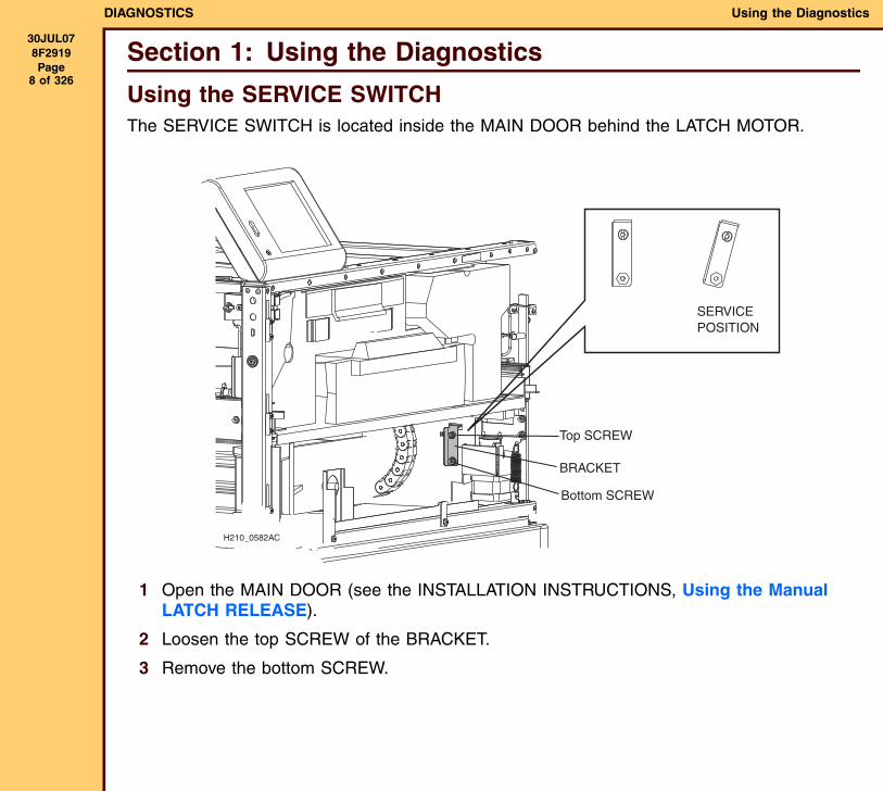
Using the SERVICE SWITCHThe SERVICE SWITCH is located inside the MAIN DOOR behind the LATCH MOTOR.
1 Open the MAIN DOOR (see the INSTALLATION INSTRUCTIONS, Using the Manual LATCH RELEASE).
2 Loosen the top SCREW of the BRACKET.
3 Remove the bottom SCREW.
H210_0582AC
SERVICEPOSITION
Top SCREW
BRACKET
Bottom SCREW
DIAGNOSTICS Using the Diagnostics
30JUL078F2919 Page
9 of 326
SERVICE TOOLFunctionsThe SERVICE TOOL provides the following functions.
• Configuration - Provides tools for configuration of the IMAGER.
• Diagnostics - Provides tools to test the components of the IMAGER.
• Hardware Data - Provides
• Logs - Provides access to logs of “events” that occur in the IMAGER.
• Monitoring and Control - Provides information about the DRE, print counts, SENSORS, and PROCESSOR temperatures.
• System Information - Provides information about the IMAGER, the service user, and software versions.
• Upgrade - Provides the ability to upgrade the DRE software and the MICROCONTROLLER applications of the MCS.
• Utilities - Provides the functions of Log Off, Restart, Shutdown, Backup and Restore, and Image File Transfer.
DIAGNOSTICS Using the Diagnostics
30JUL078F2919 Page
10 of 326
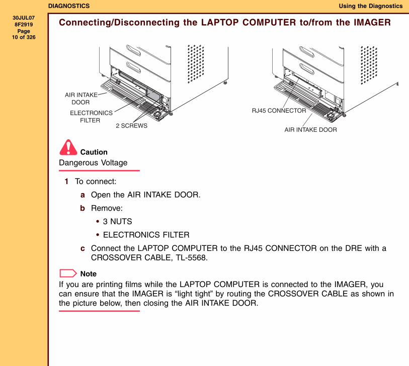
Connecting/Disconnecting the LAPTOP COMPUTER to/from the IMAGER
CautionDangerous Voltage
1 To connect:
a Open the AIR INTAKE DOOR.
b Remove:
• 3 NUTS
• ELECTRONICS FILTER
c Connect the LAPTOP COMPUTER to the RJ45 CONNECTOR on the DRE with a CROSSOVER CABLE, TL-5568.
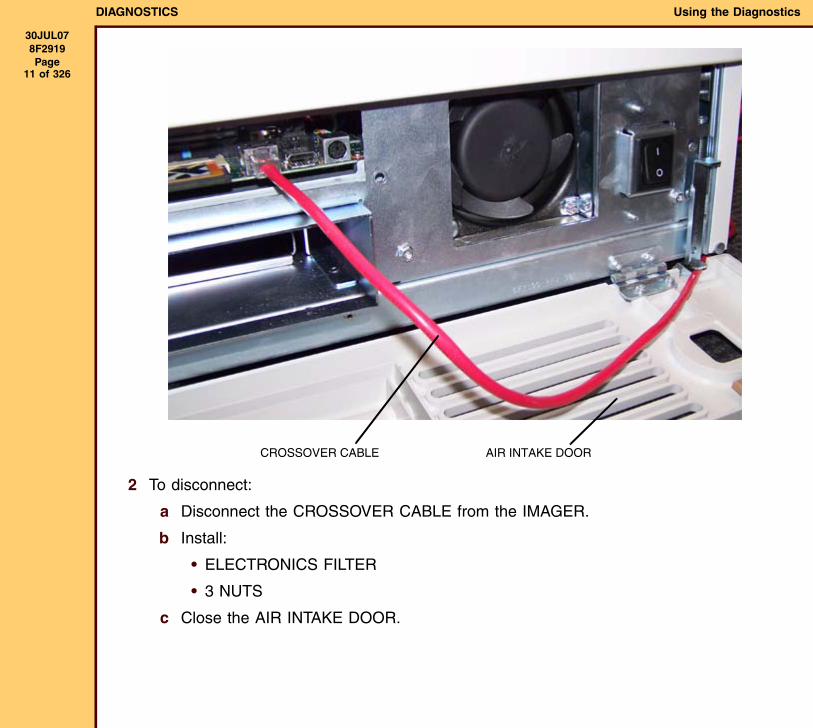
NoteIf you are printing films while the LAPTOP COMPUTER is connected to the IMAGER, you can ensure that the IMAGER is “light tight” by routing the CROSSOVER CABLE as shown in the picture below, then closing the AIR INTAKE DOOR.
AIR INTAKE DOOR
ELECTRONICS FILTER
2 SCREWS
RJ45 CONNECTOR
AIR INTAKE DOOR
DIAGNOSTICS Using the Diagnostics
30JUL078F2919 Page
11 of 326
2 To disconnect:
a Disconnect the CROSSOVER CABLE from the IMAGER.
b Install:
• ELECTRONICS FILTER
• 3 NUTS
c Close the AIR INTAKE DOOR.
CROSSOVER CABLE AIR INTAKE DOOR
DIAGNOSTICS Using the Diagnostics
30JUL078F2919 Page
12 of 326
Logging On to the SERVICE TOOL
ImportantYou must have the SECURE LINK CLIENT SOFTWARE, Version 2.1 or higher and the Service WebLink Client Software, Version 2.0 or higher installed and configured on your LAPTOP COMPUTER. Both of these are located on the Intranet at: http://know.us.kodak.com/audience_fe001/stage/global/en/Health-Medical/Service_Systems/index.shtml.
1 Connect the LAPTOP COMPUTER to the IMAGER (see Connecting/Disconnecting the LAPTOP COMPUTER to/from the IMAGER).
2 Energize the LAPTOP COMPUTER.
3 Select Start>Programs>Kodak>SecureLink.
4 Type your password.
5 Click [OK].
6 Type the IP address of the SERVICE PORT: 192.168.000.001
7 Click [Connect].
8 Select Start>Programs>Kodak>Service WebLink.
The main menu of the SERVICE TOOL displays.
Logging Off From the SERVICE TOOL1 In the upper right corner of the SERVICE TOOL, click [Log Off].
2 At the “Kodak Service WebLink” screen, click [Log Off].
3 Close the “WebLink” Client Software.
4 At the “Kodak Secure Link 2.1” screen:
• click [Disconnect]
• close the screen
5 Disconnect the LAPTOP COMPUTER from the IMAGER (see Connecting/Disconnecting the LAPTOP COMPUTER to/from the IMAGER).
DIAGNOSTICS Using the Diagnostics
30JUL078F2919 Page
13 of 326
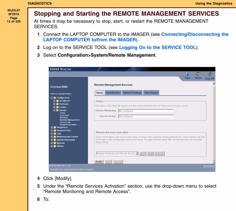
Stopping and Starting the REMOTE MANAGEMENT SERVICESAt times it may be necessary to stop, start, or restart the REMOTE MANAGEMENT SERVICES.
1 Connect the LAPTOP COMPUTER to the IMAGER (see Connecting/Disconnecting the LAPTOP COMPUTER to/from the IMAGER).
2 Log on to the SERVICE TOOL (see Logging On to the SERVICE TOOL).
3 Select Configuration>System/Remote Management.
4 Click [Modify].
5 Under the “Remote Services Activation” section, use the drop-down menu to select “Remote Monitoring and Remote Access”.
6 To:
DIAGNOSTICS Using the Diagnostics
30JUL078F2919 Page
14 of 326
• stop the agent, click [Stop]
• start the agent, click [Start]
• restart the agent, click [Restart]
7 Click [Save].
Diagnostic TestsDENSITOMETER
1 Select Diagnostics>MCS>Densitometer.
2 Click [Run].
NoteThis is the same test run at power ON for the DENSITOMETER. The test ends with a “Pass” or “Fail” indication and displays diagnostic data. The test sequence:
• De-energizes the DENSITY and FIDUCIAL LAMPS, then reads A to D counts for offset light values for the LAMPS 8 times and calculates an average. The average value must be 4096 + 400.
• De-energizes the DENSITY LAMP, then reads the A to D counts for reference brightness 8 times and averages the values. If the average A to D count is not between 750,000 and 850,000, software adjusts the count.
• De-energizes the DENSITY LAMP and energizes the FIDUCIAL LAMP. Reads the Reference brightness value 8 times and averages the values. If the average value is not between 250,000 and 550,000, software adjusts the brightness.
3 To display the results of the last DENSITOMETER test, click [Current Diagnostic Data].
4 To save the test results to a file on your LAPTOP COMPUTER, click [Export Data].
DIAGNOSTICS Using the Diagnostics
30JUL078F2919 Page
15 of 326
MOTORS
ImportantThis test is not for the ROLLBACK AY or PICKUP AY. To test these MOTORS see TRAY Diagnostics.
1 Select Diagnostics>MCS>Motors Diagnostics.
2 Set the SERVICE SWITCH in the service position.
3 From the “Select Operation” drop-down menu, select the MOTOR you want to test.
4 Click [Run].
When the test is completed, either “Pass”or “Fail” will be indicated and test status will display.
5 Click the bottom line of the screen to display test results data.
6 After completing the test, set the SERVICE SWITCH to the user position and restart the IMAGER.
DIAGNOSTICS Using the Diagnostics
30JUL078F2919 Page
16 of 326
MCS MICROCONTROLLERS
ImportantThis test is not for the ROLLBACK AY or PICKUP AY. To test these MICROCONTROLLERS see TRAY Diagnostics.
1 To test any of the MICROCONTROLLERS on the I2C bus, select Diagnostics>MCS>MCS Diagnostics.
2 From the “Select Diagnostic” drop-down menu, select the type of test. The test types include:
• “Micro Controllers” - This diagnostic runs the same tests on the MICROCONTROLLERS that are run normally during “self-test”.
• “Memory” - This diagnostic checks image memory by writing to the memory and then reading it back.
• “Reset” - This function resets the selected MICROCONTROLLER to the original condition.
NoteIf you select “Memory”, from the “Cycle” drop-down menu, select if the test should be run for “One Cycle” or “Continuous”.
3 From the “Select Operation” drop-down menu, select the MICROCONTROLLER you want to test:
NoteIf you select either “Optics” or “Sorter” from the “Select Microcontroller” menu, you must set the SERVICE SWITCH to the service position before running the test.
4 Click [Run].
Tests will run once (except if “Continuous” was selected) and display “Pass ”or “Fail.”
5 Click the bottom line of the screen to display test results data.
DIAGNOSTICS Using the Diagnostics
30JUL078F2919 Page
17 of 326
TRAY Diagnostics1 Select Diagnostics>MCS>Tray Diagnostics.
2 Set the SERVICE SWITCH in the service position.
3 From the “Select Diagnostic” drop-down menu, select “Upper Tray,” “Middle Tray,” or “Lower Tray.”
4 From the “Select Operation” drop-down menu, select the type of test. The test types include:
• “Micro Controller Test” - This test does a checksum of the MICRO code and NVRAM.
• “Reset Micro Controller” - This test esets the FILM TRAY microcontroller.
• “Open Cartridge” - This test opens the cartridge.
• “Close Cartridge” - This test closes the cartridge.
• “Pickup”- This test checks the PICKUP MOTOR and PICKUP HOME SENSOR.
• “Feed Roller Close” - This test checks the FEED ROLLER OPEN/CLOSE MOTOR and SENSOR.
• “Feed Roller Open” - This test checks the FEED ROLLER OPEN/CLOSE MOTOR and SENSOR.
• “Feed Motor” - This test checks the PICKUP FEED ROLLER DRIVE MOTOR.
• “Vacuum Pump and Valve” - This test checks the VACUUM PUMP and VALVE.
• “RF Tag” - This test causes the MCS to send a command to read data from the RF TAG. The only data returned is the Serial Number of the TAG.
• “Film Transport to Platen” - This test transports film to (TBD).
• “Film Transport to Vert. Transport” - This test transports film to (TBD).
• “Film Transport to Sorter Bin 1” - This test transports film to BIN1.
• “Film Transport to Sorter Bin 2” - This test transports film to BIN2.
• “Film Transport to Sorter Bin 3” - This test transports film to BIN3.
• “Film Transport to Sorter Bin 4” - This test transports film to BIN4.
• “Film Transport to Sorter Bin 5” - This test transports film to BIN5.
DIAGNOSTICS Using the Diagnostics
30JUL078F2919 Page
18 of 326
5 From the “Cycle” drop-down menu, select the test option, “One Cycle” or “Continuous”.
NoteIf “Continuous” is selected, the test will run until “Stop” is selected. Continuous should only be used for test and film transport to a sorter bin.
6 Click [Run].
After the test completes, “Pass”or “Fail” will be indicated and status will display.
7 Click on the bottom line of the screen to display test results.
8 After completing the test, set the SERVICE SWITCH to the user position and restart the IMAGER.
DIAGNOSTICS Using the Diagnostics
30JUL078F2919 Page
19 of 326
OPTICS
Starting the Tests
1 Select Diagnostics>MCS>Optics.
OPTICS Calibration
This calibration of the OPTICS is the same that occurs before a calibration print or when the IMAGER is energized. The calibration:
• Sets the SPINNER MOTOR to full speed and checks that it is at full speed.
• Checks laser offset and gain, and adjusts if necessary.
• Initializes the POWER MONITOR by measuring offset and “range”.
• Does calibration of the ATTENUATOR by measuring it at the full “range”.
• Does calibration of the LASER by measuring the “range” and maximum power.
1 To do a calibration of the OPTICS, select “Calibrate Optics” from the “Optics Calibration and Diagnostics” menu.
2 Click [Run].
When the calibration completes, the SCREEN will display “Status” and a “Summary” of the Calibration.
Displaying Current Calibration Data
This function displays the data from the last calibration.
1 Select “Display Current Calibration Data.”
2 Click [Run].
“Exporting” Calibration Data
This procedure allows you to send calibration data to your LAPTOP COMPUTER.
1 Select “Export Calibration Data.”
2 To format the data, click [Run].
3 To save the data to a folder on your LAPTOP COMPUTER:
DIAGNOSTICS Using the Diagnostics
30JUL078F2919 Page
20 of 326
a From the Main Menu of the SERVICE TOOL, select Diagnostics>Diag Summary.
b From the diagnostics “Summary” screen, select “Test Results.”
c From the “Diagnostic” drop-down menu, select “SDSFilmCalibDiagnostics - getFilmCalibData.”
d Click [Save].
e Store the data in a folder on the HARD DRIVE of your LAPTOP COMPUTER.
OPTICS MOTORS Tests
This diagnostic includes tests of the ATTENUATOR MOTOR and TRANSLATION MOTOR. Each test commands the MOTOR to move a preset distance, and then checks results
1 Set the SERVICE SWITCH in the service position.
2 Select “Test Optics Motors.”
3 From the “Assembly Name” drop-down menu, select the MOTOR you want to test, either “attenuator” or “translation.”
4 Click [Run].
5 Check the “Summary” window for test results.
6 When the test completes, set the SERVICE SWITCH in the user position and restart the IMAGER.
DIAGNOSTICS Using the Diagnostics
30JUL078F2919 Page
21 of 326
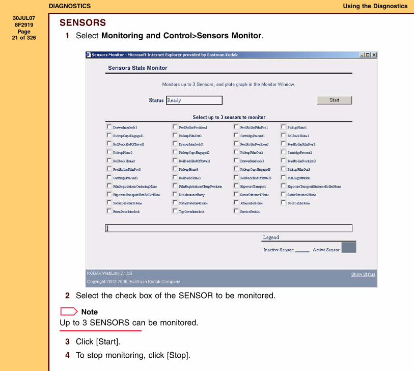
SENSORS1 Select Monitoring and Control>Sensors Monitor.
2 Select the check box of the SENSOR to be monitored.
NoteUp to 3 SENSORS can be monitored.
3 Click [Start].
4 To stop monitoring, click [Stop].
DIAGNOSTICS Using the Diagnostics
30JUL078F2919 Page
22 of 326
5 To “pause” monitoring:
• Click [Pause] to stop.
• Click [Resume] to continue.
6 To monitor the SENSORS when film is moving through the system:
a From the Main Menu of the SERVICE TOOL, select Diagnostics>DRE>Test Print.
b Select an image to print from the drop-down menu.
c Click [Run].
d Observe the “Monitor Sensors” screen to see changes in condition of the SENSORS
7 To see a “plot” of the operation of up to 3 selected SENSORS on the “Graph Sensors” screen:
a Start a test print.
b When the print is running, return to the “Monitor Sensors” screen and select the SENSORS you want to monitor.
c Click the “Graph Sensors” tab.
d Click [Run].
e Observe the screen.
DIAGNOSTICS Using the Diagnostics
30JUL078F2919 Page
23 of 326
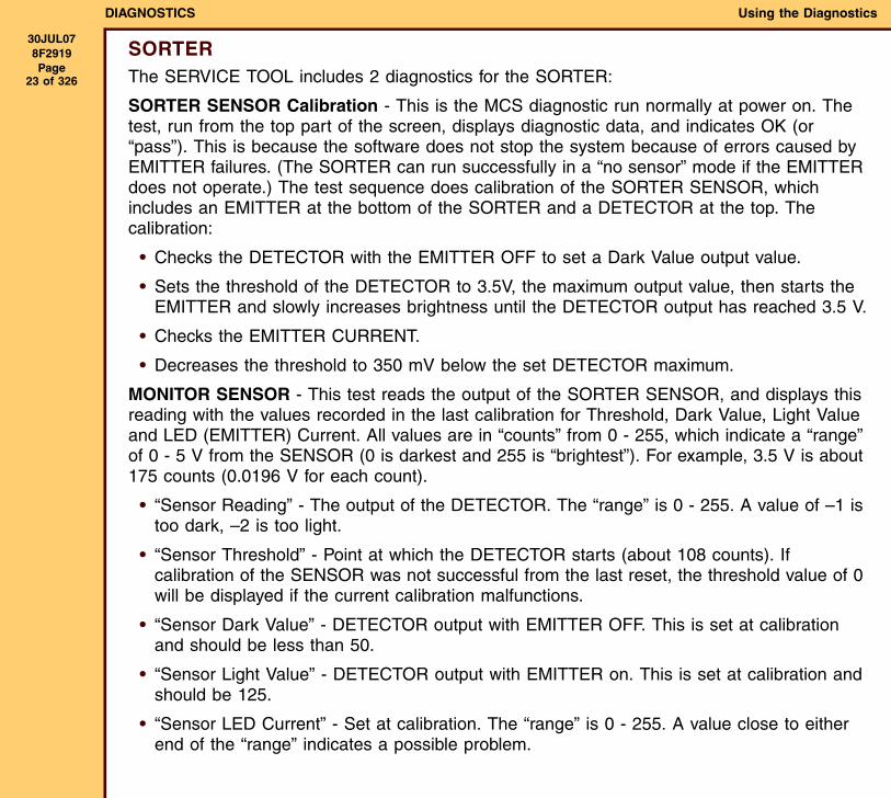
SORTERThe SERVICE TOOL includes 2 diagnostics for the SORTER:
SORTER SENSOR Calibration - This is the MCS diagnostic run normally at power on. The test, run from the top part of the screen, displays diagnostic data, and indicates OK (or “pass”). This is because the software does not stop the system because of errors caused by EMITTER failures. (The SORTER can run successfully in a “no sensor” mode if the EMITTER does not operate.) The test sequence does calibration of the SORTER SENSOR, which includes an EMITTER at the bottom of the SORTER and a DETECTOR at the top. The calibration:
• Checks the DETECTOR with the EMITTER OFF to set a Dark Value output value.
• Sets the threshold of the DETECTOR to 3.5V, the maximum output value, then starts the EMITTER and slowly increases brightness until the DETECTOR output has reached 3.5 V.
• Checks the EMITTER CURRENT.
• Decreases the threshold to 350 mV below the set DETECTOR maximum.
MONITOR SENSOR - This test reads the output of the SORTER SENSOR, and displays this reading with the values recorded in the last calibration for Threshold, Dark Value, Light Value and LED (EMITTER) Current. All values are in “counts” from 0 - 255, which indicate a “range” of 0 - 5 V from the SENSOR (0 is darkest and 255 is “brightest”). For example, 3.5 V is about 175 counts (0.0196 V for each count).
• “Sensor Reading” - The output of the DETECTOR. The “range” is 0 - 255. A value of –1 is too dark, –2 is too light.
• “Sensor Threshold” - Point at which the DETECTOR starts (about 108 counts). If calibration of the SENSOR was not successful from the last reset, the threshold value of 0 will be displayed if the current calibration malfunctions.
• “Sensor Dark Value” - DETECTOR output with EMITTER OFF. This is set at calibration and should be less than 50.
• “Sensor Light Value” - DETECTOR output with EMITTER on. This is set at calibration and should be 125.
• “Sensor LED Current” - Set at calibration. The “range” is 0 - 255. A value close to either end of the “range” indicates a possible problem.
DIAGNOSTICS Using the Diagnostics
30JUL078F2919 Page
24 of 326
1 To check operation of the SORTER SENSOR, select Diagnostics>MCS>Sorter.
2 To do calibration of the SORTER SENSOR:
a Set the SERVICE SWITCH in the “Service” mode.
b In the top right corner of the screen, click [Run].
The calibration will run and indicate OK. The results will display on the “Monitor Sensor Charts”. You must use the “charts” to determine if a failure occurred. For example, if the EMITTER does not cause enough light at the DETECTOR, the “Sensor Reading” will be -1 and the “Sensor LED Current” will be 255.
c To end monitoring, on the lower part of the screen, click [Stop].
3 To display the output of the SORTER SENSOR with the results of the last calibration:
a On the “Monitor Sensor” area of the screen, click [Run].
b To stop monitoring, click [Stop].
4 After completing the diagnostic, set the SERVICE SWITCH in the user position and restart the IMAGER.
DIAGNOSTICS Using the Diagnostics
30JUL078F2919 Page
25 of 326
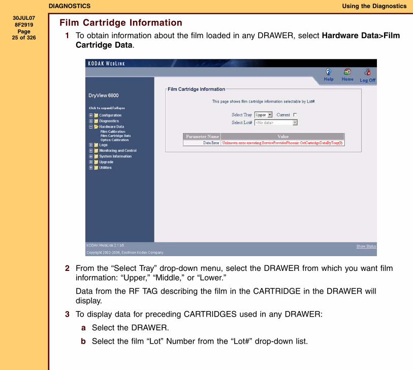
Film Cartridge Information1 To obtain information about the film loaded in any DRAWER, select Hardware Data>Film
Cartridge Data.
2 From the “Select Tray” drop-down menu, select the DRAWER from which you want film information: “Upper,” “Middle,” or “Lower.”
Data from the RF TAG describing the film in the CARTRIDGE in the DRAWER will display.
3 To display data for preceding CARTRIDGES used in any DRAWER:
a Select the DRAWER.
b Select the film “Lot” Number from the “Lot#” drop-down list.
DIAGNOSTICS Using the Diagnostics
30JUL078F2919 Page
26 of 326
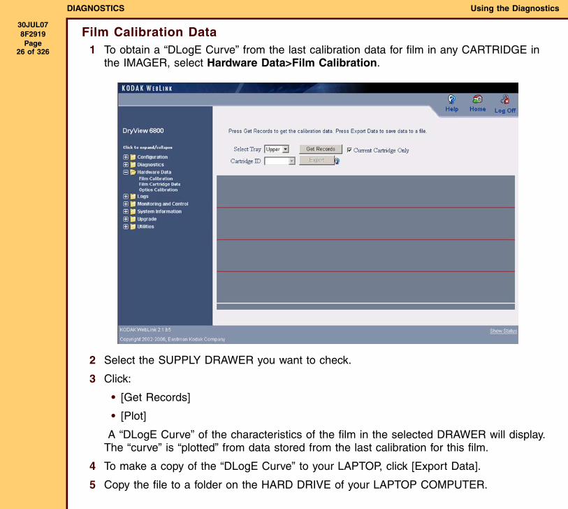
Film Calibration Data1 To obtain a “DLogE Curve” from the last calibration data for film in any CARTRIDGE in
the IMAGER, select Hardware Data>Film Calibration.
2 Select the SUPPLY DRAWER you want to check.
3 Click:
• [Get Records]
• [Plot]
A “DLogE Curve” of the characteristics of the film in the selected DRAWER will display. The “curve” is “plotted” from data stored from the last calibration for this film.
4 To make a copy of the “DLogE Curve” to your LAPTOP, click [Export Data].
5 Copy the file to a folder on the HARD DRIVE of your LAPTOP COMPUTER.
DIAGNOSTICS Using the Diagnostics
30JUL078F2919 Page
27 of 326
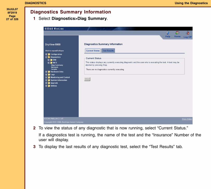
Diagnostics Summary Information1 Select Diagnostics>Diag Summary.
2 To view the status of any diagnostic that is now running, select “Current Status.”
If a diagnostics test is running, the name of the test and the “Insurance” Number of the user will display.
3 To display the last results of any diagnostic test, select the “Test Results” tab.
DIAGNOSTICS Using the Diagnostics
30JUL078F2919 Page
28 of 326
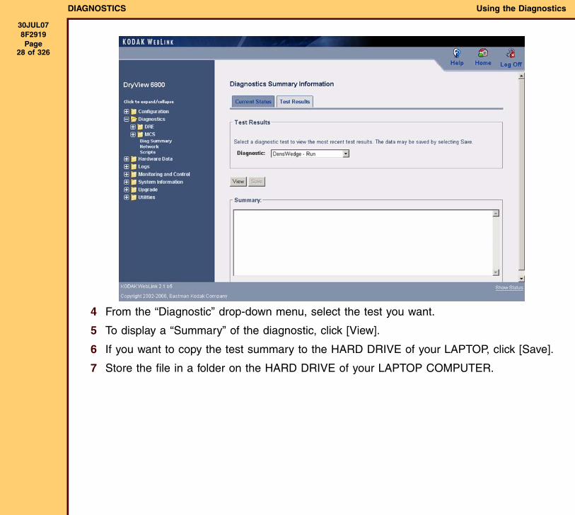
4 From the “Diagnostic” drop-down menu, select the test you want.
5 To display a “Summary” of the diagnostic, click [View].
6 If you want to copy the test summary to the HARD DRIVE of your LAPTOP, click [Save].
7 Store the file in a folder on the HARD DRIVE of your LAPTOP COMPUTER.
DIAGNOSTICS Using the Diagnostics
30JUL078F2919 Page
29 of 326
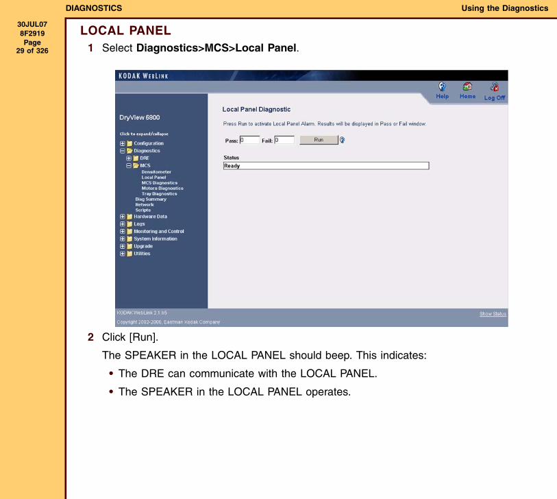
LOCAL PANEL1 Select Diagnostics>MCS>Local Panel.
2 Click [Run].
The SPEAKER in the LOCAL PANEL should beep. This indicates:
• The DRE can communicate with the LOCAL PANEL.
• The SPEAKER in the LOCAL PANEL operates.
DIAGNOSTICS Using the Diagnostics
30JUL078F2919 Page
30 of 326
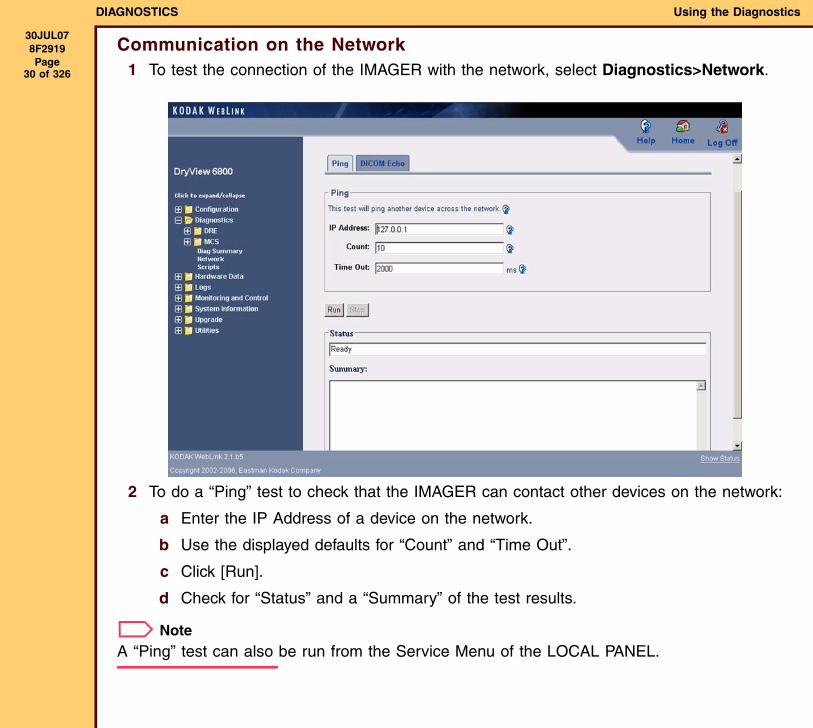
Communication on the Network1 To test the connection of the IMAGER with the network, select Diagnostics>Network.
2 To do a “Ping” test to check that the IMAGER can contact other devices on the network:
a Enter the IP Address of a device on the network.
b Use the displayed defaults for “Count” and “Time Out”.
c Click [Run].
d Check for “Status” and a “Summary” of the test results.
NoteA “Ping” test can also be run from the Service Menu of the LOCAL PANEL.
DIAGNOSTICS Using the Diagnostics
30JUL078F2919 Page
31 of 326
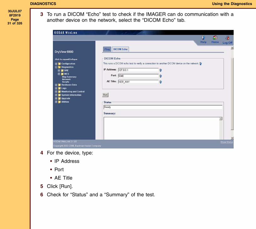
3 To run a DICOM “Echo” test to check if the IMAGER can do communication with a another device on the network, select the “DICOM Echo” tab.
4 For the device, type:
• IP Address
• Port
• AE Title
5 Click [Run].
6 Check for “Status” and a “Summary” of the test.
DIAGNOSTICS Using the Diagnostics
30JUL078F2919 Page
32 of 326
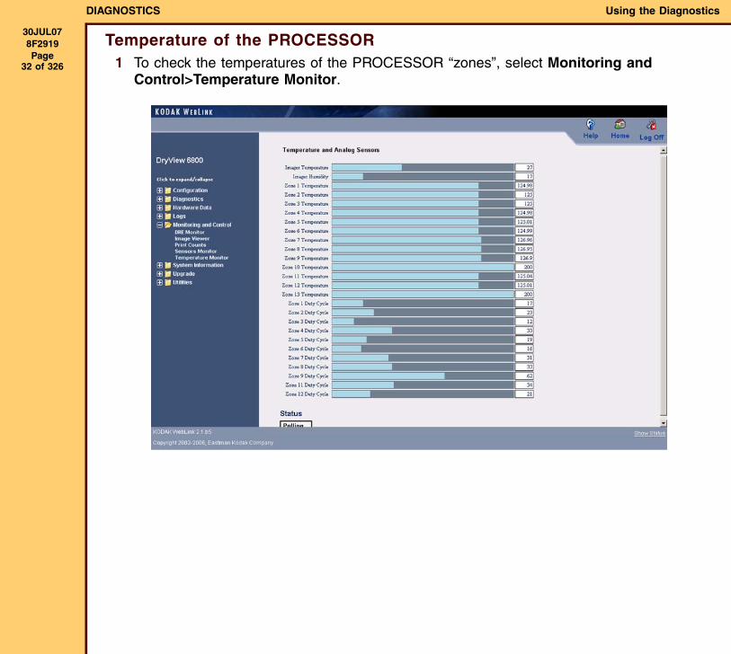
Temperature of the PROCESSOR1 To check the temperatures of the PROCESSOR “zones”, select Monitoring and
Control>Temperature Monitor.
DIAGNOSTICS Using the Diagnostics
30JUL078F2919 Page
33 of 326
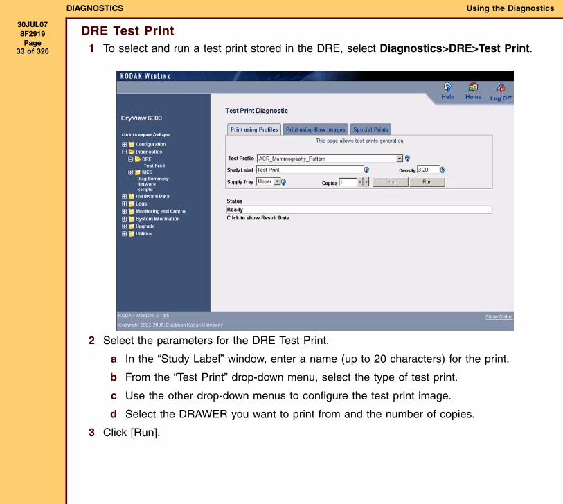
DRE Test Print1 To select and run a test print stored in the DRE, select Diagnostics>DRE>Test Print.
2 Select the parameters for the DRE Test Print.
a In the “Study Label” window, enter a name (up to 20 characters) for the print.
b From the “Test Print” drop-down menu, select the type of test print.
c Use the other drop-down menus to configure the test print image.
d Select the DRAWER you want to print from and the number of copies.
3 Click [Run].
DIAGNOSTICS Using the Diagnostics
30JUL078F2919 Page
34 of 326
Power-on “Self-Tests”“Self-test” and calibration are automatically run by the system when power is applied. If an error occurs, an error code is displayed on the LOCAL PANEL. Under control of the MCS MASTER CPU, tests and calibration are run by MICROCONTROLLERS that control the other BOARDS on the I2C bus of the MCS. After the PROCESSOR tests are run, the MCS MASTER CPU starts 3 tracks of diagnostics. In 1 track, diagnostics are run for the closed SUPPLY DRAWERS, 1 at a time, until the test has run for all DRAWERS. In the other 2 tracks, the MCS starts diagnostics for the remaining MICROCONTROLLERS in the system. The tests in the 3 tracks are run at the same time.
The “self-tests” and calibration run by the system are:
• MCS Diagnostics
• MCS Clear Films
• PROCESSOR Diagnostics
• RF TAG Diagnostics
• DENSITOMETER Diagnostics
• SORTER Diagnostics
• SUPPLY DRAWER Diagnostics - CARTRIDGE CONTROLLER
• SUPPLY DRAWER Diagnostics - TRAY Diagnostics
• OPTICS Diagnostics
• OPTICS Calibration
DIAGNOSTICS Using the Diagnostics
30JUL078F2919 Page
35 of 326
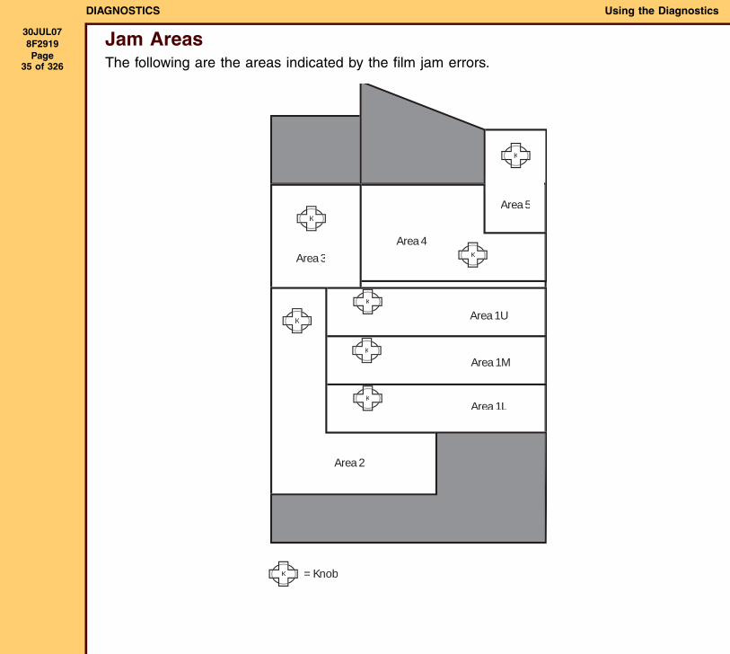
Jam AreasThe following are the areas indicated by the film jam errors.
K
K
K
K
K
K
K
K
= Knob
Area 1L
Area 1M
Area 1U
Area 2
Area 3
Area 4
Area 5
DIAGNOSTICS Status Messages and Error Codes
30JUL078F2919 Page
36 of 326
Section 2: Status Messages and Error Codes
OverviewThis section provides information about 5 types of system messages:
• DICOM status messages from the LASER IMAGER to the SCU
• PRINTER status messages displayed on the LOCAL PANEL
• FILM TRAY status messages displayed on the LOCAL PANEL
• JOB MANAGER status messages displayed on the LOCAL PANEL
• LASER IMAGER error codes and messages displayed on the LOCAL PANEL and status messages written to the system log
DICOM Status MessagesA PRINTER Status Message and a PRINTER STATUS INFO message are returned to the “requesting” SERVICE CLASS USER (SCU) in response to a DICOM PRINTER N-GET status “request”.
Every error has an “associated” DICOM PRINTER STATUS INFO message (some errors have the same PRINTER STATUS INFO message).
• If no errors occur when a PRINTER N-GET “request” is received, a PRINTER STATUS INFO message of “NORMAL” is returned.
• If only one error occurs, a PRINTER STATUS INFO message corresponding to that error is sent back in response.
• If more than one error occurs when a PRINTER N-GET “request” is received, a PRINTER STATUS INFO message is selected by the following priority:
1. errors returned in the same order generated
2. “non-normal” PRINTER status
3. empty film
4. normal status
DIAGNOSTICS Status Messages and Error Codes
30JUL078F2919 Page
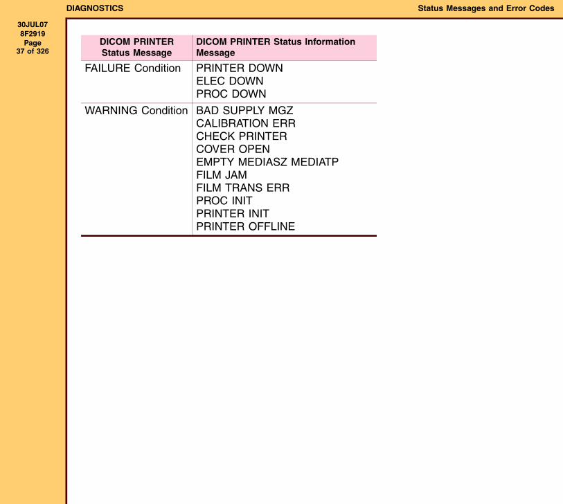
37 of 326DICOM PRINTER Status Message
DICOM PRINTER Status Information Message
FAILURE Condition PRINTER DOWNELEC DOWNPROC DOWN
WARNING Condition BAD SUPPLY MGZCALIBRATION ERRCHECK PRINTERCOVER OPENEMPTY MEDIASZ MEDIATPFILM JAMFILM TRANS ERRPROC INITPRINTER INITPRINTER OFFLINE
DIAGNOSTICS Status Messages and Error Codes
30JUL078F2919 Page
38 of 326
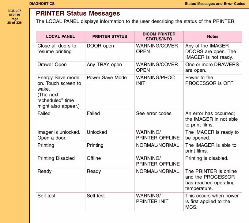
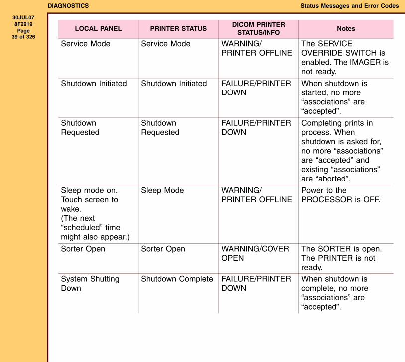
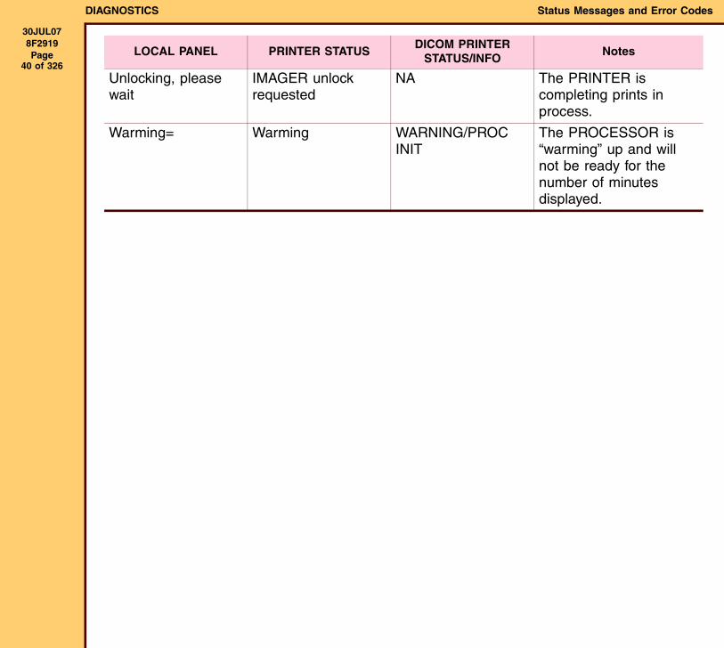
PRINTER Status MessagesThe LOCAL PANEL displays information to the user describing the status of the PRINTER.
LOCAL PANEL PRINTER STATUSDICOM PRINTER
STATUS/INFONotes
Close all doors to resume printing
DOOR open WARNING/COVER OPEN
Any of the IMAGER DOORS are open. The IMAGER is not ready.
Drawer Open Any TRAY open WARNING/COVER OPEN
One or more DRAWERS are open.
Energy Save mode on. Touch screen to wake. (The next “scheduled” time might also appear.)
Power Save Mode WARNING/PROC INIT
Power to the PROCESSOR is OFF.
Failed Failed See error codes An error has occurred; the IMAGER in not able to print films.
Imager is unlocked. Open a door.
Unlocked WARNING/PRINTER OFFLINE
The IMAGER is ready to be opened.
Printing Printing NORMAL/NORMAL The IMAGER is able to print films.
Printing Disabled Offline WARNING/PRINTER OFFLINE
Printing is disabled.
Ready Ready NORMAL/NORMAL The PRINTER is online and the PROCESSOR has reached operating temperature.
Self-test Self-test WARNING/PRINTER INIT
This occurs when power is first applied to the MCS.
DIAGNOSTICS Status Messages and Error Codes
30JUL078F2919 Page
39 of 326Service Mode Service Mode WARNING/
PRINTER OFFLINEThe SERVICE OVERRIDE SWITCH is enabled. The IMAGER is not ready.
Shutdown Initiated Shutdown Initiated FAILURE/PRINTER DOWN
When shutdown is started, no more “associations” are “accepted”.
Shutdown Requested
Shutdown Requested
FAILURE/PRINTER DOWN
Completing prints in process. When shutdown is asked for, no more “associations” are “accepted” and existing “associations” are “aborted”.
Sleep mode on. Touch screen to wake. (The next “scheduled” time might also appear.)
Sleep Mode WARNING/PRINTER OFFLINE
Power to the PROCESSOR is OFF.
Sorter Open Sorter Open WARNING/COVER OPEN
The SORTER is open. The PRINTER is not ready.
System Shutting Down
Shutdown Complete FAILURE/PRINTER DOWN
When shutdown is complete, no more “associations” are “accepted”.
LOCAL PANEL PRINTER STATUSDICOM PRINTER
STATUS/INFONotes
DIAGNOSTICS Status Messages and Error Codes
30JUL078F2919 Page
40 of 326Unlocking, please wait
IMAGER unlock requested
NA The PRINTER is completing prints in process.
Warming= Warming WARNING/PROC INIT
The PROCESSOR is “warming” up and will not be ready for the number of minutes displayed.
LOCAL PANEL PRINTER STATUSDICOM PRINTER
STATUS/INFONotes
DIAGNOSTICS Status Messages and Error Codes
30JUL078F2919 Page
41 of 326
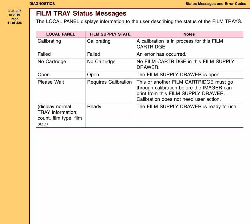
FILM TRAY Status MessagesThe LOCAL PANEL displays information to the user describing the status of the FILM TRAYS.
LOCAL PANEL FILM SUPPLY STATE Notes
Calibrating Calibrating A calibration is in process for this FILM CARTRIDGE.
Failed Failed An error has occurred.
No Cartridge No Cartridge No FILM CARTRIDGE in this FILM SUPPLY DRAWER.
Open Open The FILM SUPPLY DRAWER is open.
Please Wait Requires Calibration This or another FILM CARTRIDGE must go through calibration before the IMAGER can print from this FILM SUPPLY DRAWER. Calibration does not need user action.
(display normal TRAY information; count, film type, film size)
Ready The FILM SUPPLY DRAWER is ready to use.
DIAGNOSTICS Status Messages and Error Codes
30JUL078F2919 Page
42 of 326
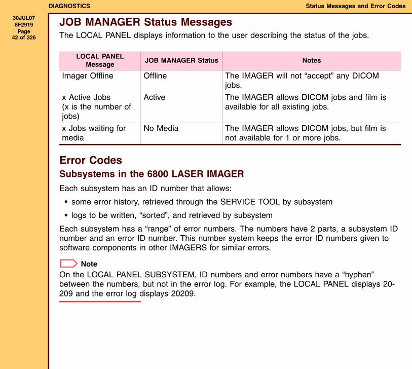
JOB MANAGER Status MessagesThe LOCAL PANEL displays information to the user describing the status of the jobs.
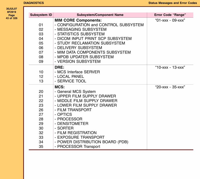
Error CodesSubsystems in the 6800 LASER IMAGEREach subsystem has an ID number that allows:
• some error history, retrieved through the SERVICE TOOL by subsystem
• logs to be written, “sorted”, and retrieved by subsystem
Each subsystem has a “range” of error numbers. The numbers have 2 parts, a subsystem ID number and an error ID number. This number system keeps the error ID numbers given to software components in other IMAGERS for similar errors.
NoteOn the LOCAL PANEL SUBSYSTEM, ID numbers and error numbers have a “hyphen” between the numbers, but not in the error log. For example, the LOCAL PANEL displays 20-209 and the error log displays 20209.
LOCAL PANEL Message
JOB MANAGER Status Notes
Imager Offline Offline The IMAGER will not “accept” any DICOM jobs.
x Active Jobs(x is the number of jobs)
Active The IMAGER allows DICOM jobs and film is available for all existing jobs.
x Jobs waiting for media
No Media The IMAGER allows DICOM jobs, but film is not available for 1 or more jobs.
DIAGNOSTICS Status Messages and Error Codes
30JUL078F2919 Page
43 of 326Subsystem ID Subsystem/Component Name Error Code “Range”
010203040506070809
MIM CORE Components:- CONFIGURATION and CONTROL SUBSYSTEM- MESSAGING SUBSYSTEM- STATISTICS SUBSYSTEM- DICOM INPUT PRINT SCP SUBSYSTEM- STUDY RECLAMATION SUBSYSTEM- DELIVERY SUBSYSTEM- MIM DATA COMPONENTS SUBSYSTEM- MPDB UPDATER SUBSYSTEM- VERSION SUBSYSTEM
“01-xxx - 09-xxx”
101213
DRE:- MCS Interface SERVER- LOCAL PANEL- SERVICE TOOL
“10-xxx - 13-xxx”
20212223262728293032333435
MCS:- General MCS System- UPPER FILM SUPPLY DRAWER- MIDDLE FILM SUPPLY DRAWER- LOWER FILM SUPPLY DRAWER- FILM TRANSPORT- OPTICS- PROCESSOR- DENSITOMETER- SORTER- FILM REGISTRATION- EXPOSURE TRANSPORT- POWER DISTRIBUTION BOARD (PDB)- PROCESSOR Transport
“20-xxx - 35-xxx”
DIAGNOSTICS Status Messages and Error Codes
30JUL078F2919 Page
44 of 326
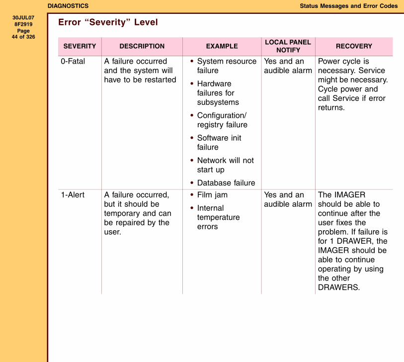
Error “Severity” Level
SEVERITY DESCRIPTION EXAMPLELOCAL PANEL
NOTIFYRECOVERY
0-Fatal A failure occurred and the system will have to be restarted
• System resource failure
• Hardware failures for subsystems
• Configuration/registry failure
• Software init failure
• Network will not start up
• Database failure
Yes and an audible alarm
Power cycle is necessary. Service might be necessary. Cycle power and call Service if error returns.
1-Alert A failure occurred, but it should be temporary and can be repaired by the user.
• Film jam
• Internal temperature errors
Yes and an audible alarm
The IMAGER should be able to continue after the user fixes the problem. If failure is for 1 DRAWER, the IMAGER should be able to continue operating by using the other DRAWERS.
DIAGNOSTICS Status Messages and Error Codes
30JUL078F2919 Page
45 of 326
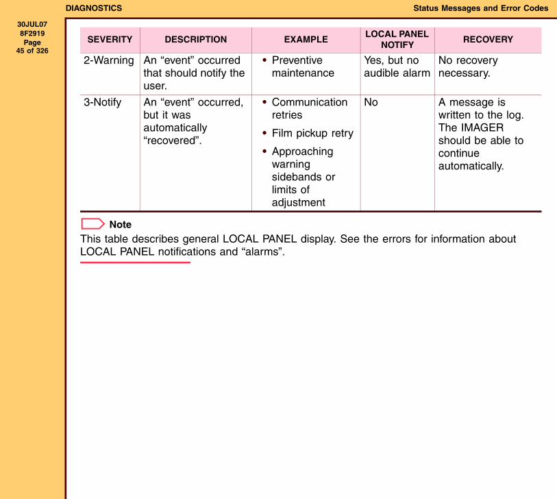
NoteThis table describes general LOCAL PANEL display. See the errors for information about LOCAL PANEL notifications and “alarms”.
2-Warning An “event” occurred that should notify the user.
• Preventive maintenance
Yes, but no audible alarm
No recovery necessary.
3-Notify An “event” occurred, but it was automatically “recovered”.
• Communication retries
• Film pickup retry
• Approaching warning sidebands or limits of adjustment
No A message is written to the log. The IMAGER should be able to continue automatically.
SEVERITY DESCRIPTION EXAMPLELOCAL PANEL
NOTIFYRECOVERY
DIAGNOSTICS Status Messages and Error Codes
30JUL078F2919 Page
46 of 326
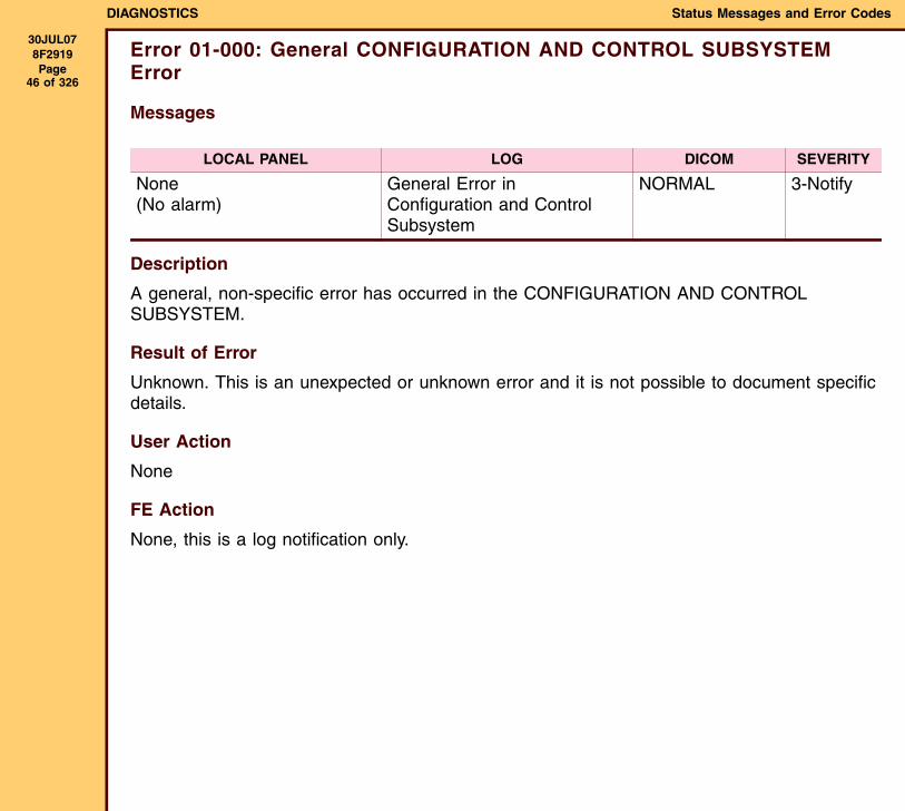
Error 01-000: General CONFIGURATION AND CONTROL SUBSYSTEM Error
Messages
Description
A general, non-specific error has occurred in the CONFIGURATION AND CONTROL SUBSYSTEM.
Result of Error
Unknown. This is an unexpected or unknown error and it is not possible to document specific details.
User Action
None
FE Action
None, this is a log notification only.
LOCAL PANEL LOG DICOM SEVERITY
None(No alarm)
General Error in Configuration and Control Subsystem
NORMAL 3-Notify
DIAGNOSTICS Status Messages and Error Codes
30JUL078F2919 Page
47 of 326
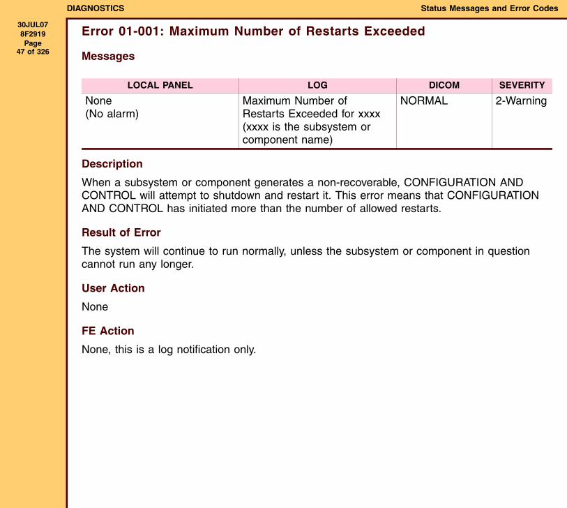
Error 01-001: Maximum Number of Restarts Exceeded
Messages
Description
When a subsystem or component generates a non-recoverable, CONFIGURATION AND CONTROL will attempt to shutdown and restart it. This error means that CONFIGURATION AND CONTROL has initiated more than the number of allowed restarts.
Result of Error
The system will continue to run normally, unless the subsystem or component in question cannot run any longer.
User Action
None
FE Action
None, this is a log notification only.
LOCAL PANEL LOG DICOM SEVERITY
None(No alarm)
Maximum Number of Restarts Exceeded for xxxx (xxxx is the subsystem or component name)
NORMAL 2-Warning
DIAGNOSTICS Status Messages and Error Codes
30JUL078F2919 Page
48 of 326
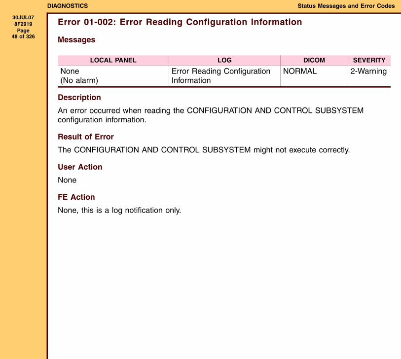
Error 01-002: Error Reading Configuration Information
Messages
Description
An error occurred when reading the CONFIGURATION AND CONTROL SUBSYSTEM configuration information.
Result of Error
The CONFIGURATION AND CONTROL SUBSYSTEM might not execute correctly.
User Action
None
FE Action
None, this is a log notification only.
LOCAL PANEL LOG DICOM SEVERITY
None(No alarm)
Error Reading Configuration Information
NORMAL 2-Warning
DIAGNOSTICS Status Messages and Error Codes
30JUL078F2919 Page
49 of 326
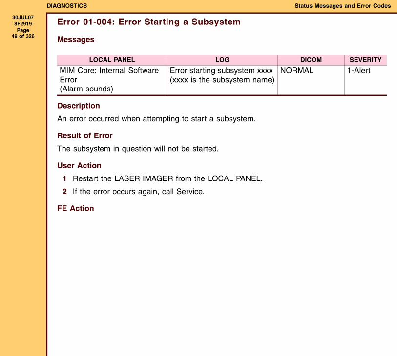
Error 01-004: Error Starting a Subsystem
Messages
Description
An error occurred when attempting to start a subsystem.
Result of Error
The subsystem in question will not be started.
User Action
1 Restart the LASER IMAGER from the LOCAL PANEL.
2 If the error occurs again, call Service.
FE Action
LOCAL PANEL LOG DICOM SEVERITY
MIM Core: Internal Software Error(Alarm sounds)
Error starting subsystem xxxx (xxxx is the subsystem name)
NORMAL 1-Alert
DIAGNOSTICS Status Messages and Error Codes
30JUL078F2919 Page
50 of 326
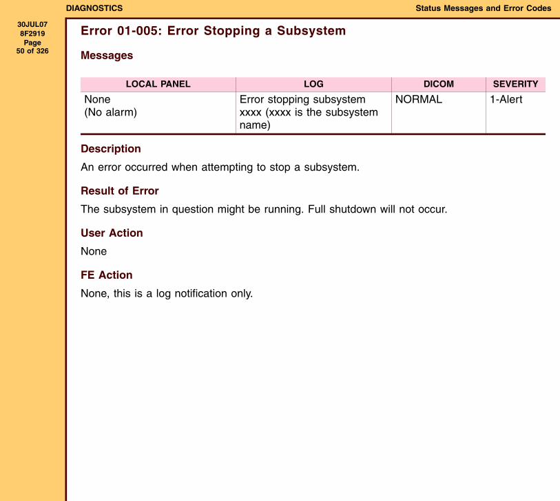
Error 01-005: Error Stopping a Subsystem
Messages
Description
An error occurred when attempting to stop a subsystem.
Result of Error
The subsystem in question might be running. Full shutdown will not occur.
User Action
None
FE Action
None, this is a log notification only.
LOCAL PANEL LOG DICOM SEVERITY
None(No alarm)
Error stopping subsystem xxxx (xxxx is the subsystem name)
NORMAL 1-Alert
DIAGNOSTICS Status Messages and Error Codes
30JUL078F2919 Page
51 of 326
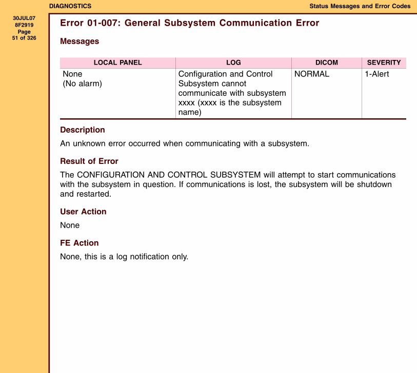
Error 01-007: General Subsystem Communication Error
Messages
Description
An unknown error occurred when communicating with a subsystem.
Result of Error
The CONFIGURATION AND CONTROL SUBSYSTEM will attempt to start communications with the subsystem in question. If communications is lost, the subsystem will be shutdown and restarted.
User Action
None
FE Action
None, this is a log notification only.
LOCAL PANEL LOG DICOM SEVERITY
None(No alarm)
Configuration and Control Subsystem cannot communicate with subsystem xxxx (xxxx is the subsystem name)
NORMAL 1-Alert
DIAGNOSTICS Status Messages and Error Codes
30JUL078F2919 Page
52 of 326
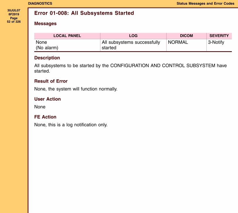
Error 01-008: All Subsystems Started
Messages
Description
All subsystems to be started by the CONFIGURATION AND CONTROL SUBSYSTEM have started.
Result of Error
None, the system will function normally.
User Action
None
FE Action
None, this is a log notification only.
LOCAL PANEL LOG DICOM SEVERITY
None(No alarm)
All subsystems successfully started
NORMAL 3-Notify
DIAGNOSTICS Status Messages and Error Codes
30JUL078F2919 Page
53 of 326
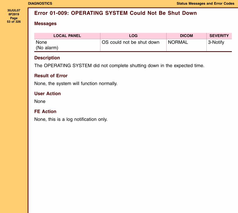
Error 01-009: OPERATING SYSTEM Could Not Be Shut Down
Messages
Description
The OPERATING SYSTEM did not complete shutting down in the expected time.
Result of Error
None, the system will function normally.
User Action
None
FE Action
None, this is a log notification only.
LOCAL PANEL LOG DICOM SEVERITY
None(No alarm)
OS could not be shut down NORMAL 3-Notify
DIAGNOSTICS Status Messages and Error Codes
30JUL078F2919 Page
54 of 326
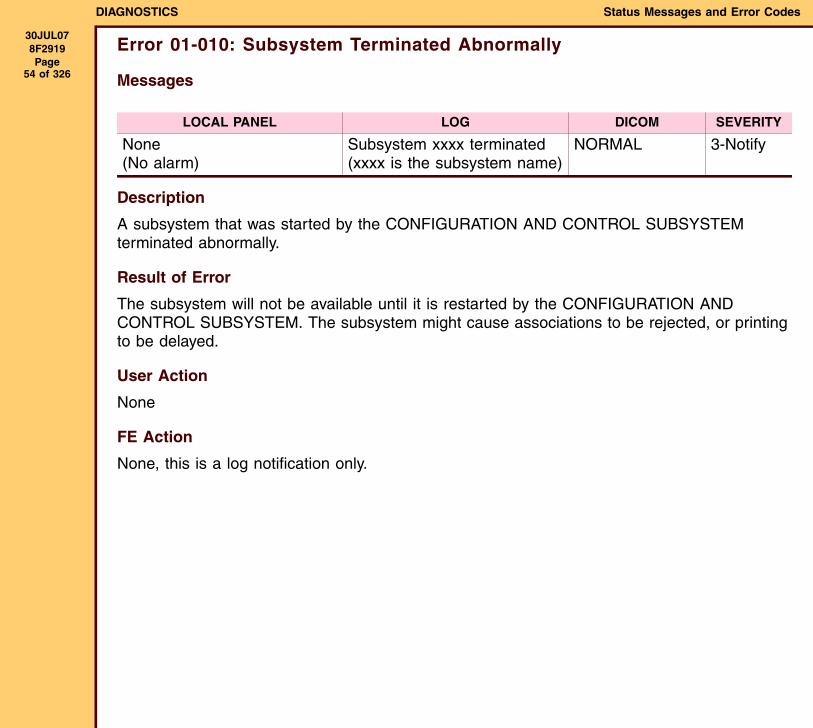
Error 01-010: Subsystem Terminated Abnormally
Messages
Description
A subsystem that was started by the CONFIGURATION AND CONTROL SUBSYSTEM terminated abnormally.
Result of Error
The subsystem will not be available until it is restarted by the CONFIGURATION AND CONTROL SUBSYSTEM. The subsystem might cause associations to be rejected, or printing to be delayed.
User Action
None
FE Action
None, this is a log notification only.
LOCAL PANEL LOG DICOM SEVERITY
None(No alarm)
Subsystem xxxx terminated (xxxx is the subsystem name)
NORMAL 3-Notify
DIAGNOSTICS Status Messages and Error Codes
30JUL078F2919 Page
55 of 326
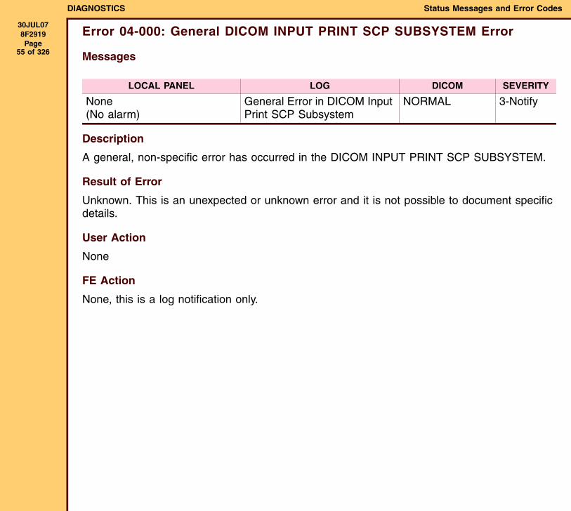
Error 04-000: General DICOM INPUT PRINT SCP SUBSYSTEM Error
Messages
Description
A general, non-specific error has occurred in the DICOM INPUT PRINT SCP SUBSYSTEM.
Result of Error
Unknown. This is an unexpected or unknown error and it is not possible to document specific details.
User Action
None
FE Action
None, this is a log notification only.
LOCAL PANEL LOG DICOM SEVERITY
None(No alarm)
General Error in DICOM Input Print SCP Subsystem
NORMAL 3-Notify
DIAGNOSTICS Status Messages and Error Codes
30JUL078F2919 Page
56 of 326
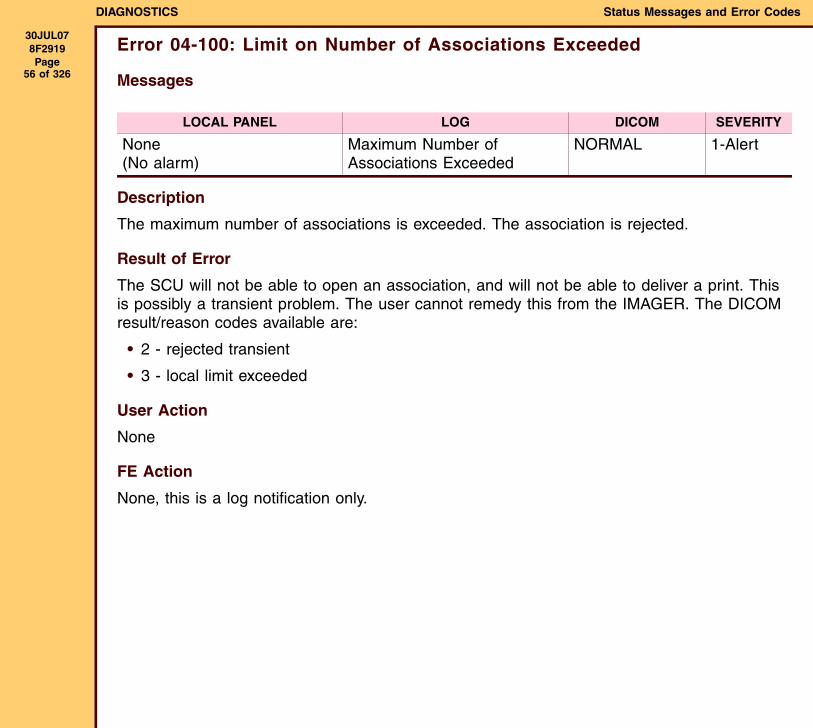
Error 04-100: Limit on Number of Associations Exceeded
Messages
Description
The maximum number of associations is exceeded. The association is rejected.
Result of Error
The SCU will not be able to open an association, and will not be able to deliver a print. This is possibly a transient problem. The user cannot remedy this from the IMAGER. The DICOM result/reason codes available are:
• 2 - rejected transient
• 3 - local limit exceeded
User Action
None
FE Action
None, this is a log notification only.
LOCAL PANEL LOG DICOM SEVERITY
None(No alarm)
Maximum Number of Associations Exceeded
NORMAL 1-Alert
DIAGNOSTICS Status Messages and Error Codes
30JUL078F2919 Page
57 of 326
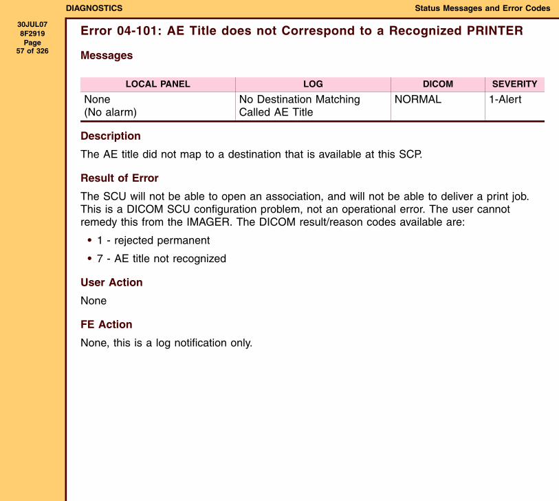
Error 04-101: AE Title does not Correspond to a Recognized PRINTER
Messages
Description
The AE title did not map to a destination that is available at this SCP.
Result of Error
The SCU will not be able to open an association, and will not be able to deliver a print job. This is a DICOM SCU configuration problem, not an operational error. The user cannot remedy this from the IMAGER. The DICOM result/reason codes available are:
• 1 - rejected permanent
• 7 - AE title not recognized
User Action
None
FE Action
None, this is a log notification only.
LOCAL PANEL LOG DICOM SEVERITY
None(No alarm)
No Destination Matching Called AE Title
NORMAL 1-Alert
DIAGNOSTICS Status Messages and Error Codes
30JUL078F2919 Page
58 of 326
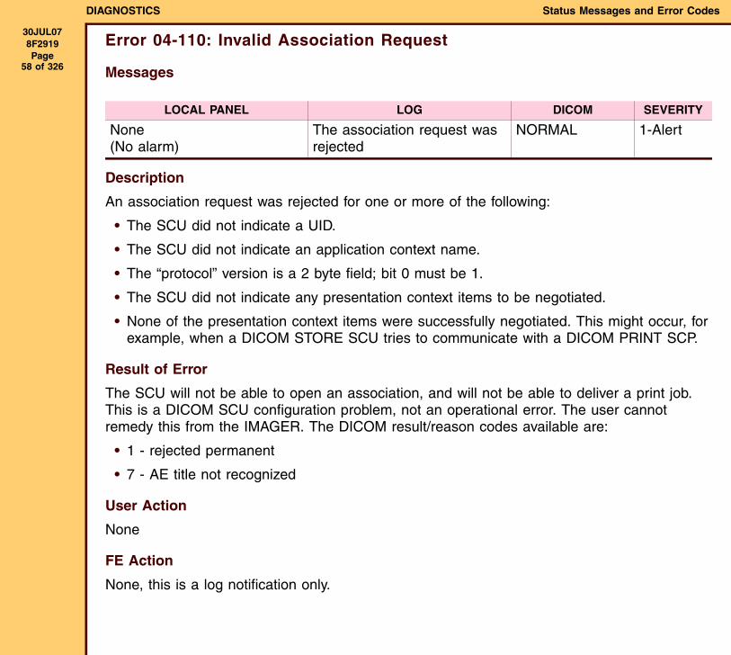
Error 04-110: Invalid Association Request
Messages
Description
An association request was rejected for one or more of the following:
• The SCU did not indicate a UID.
• The SCU did not indicate an application context name.
• The “protocol” version is a 2 byte field; bit 0 must be 1.
• The SCU did not indicate any presentation context items to be negotiated.
• None of the presentation context items were successfully negotiated. This might occur, for example, when a DICOM STORE SCU tries to communicate with a DICOM PRINT SCP.
Result of Error
The SCU will not be able to open an association, and will not be able to deliver a print job. This is a DICOM SCU configuration problem, not an operational error. The user cannot remedy this from the IMAGER. The DICOM result/reason codes available are:
• 1 - rejected permanent
• 7 - AE title not recognized
User Action
None
FE Action
None, this is a log notification only.
LOCAL PANEL LOG DICOM SEVERITY
None(No alarm)
The association request was rejected
NORMAL 1-Alert
DIAGNOSTICS Status Messages and Error Codes
30JUL078F2919 Page
59 of 326
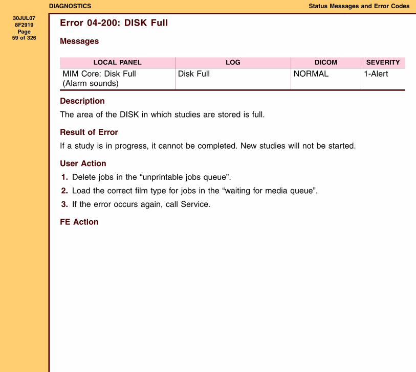
Error 04-200: DISK Full
Messages
Description
The area of the DISK in which studies are stored is full.
Result of Error
If a study is in progress, it cannot be completed. New studies will not be started.
User Action
1. Delete jobs in the “unprintable jobs queue”.
2. Load the correct film type for jobs in the “waiting for media queue”.
3. If the error occurs again, call Service.
FE Action
LOCAL PANEL LOG DICOM SEVERITY
MIM Core: Disk Full(Alarm sounds)
Disk Full NORMAL 1-Alert
DIAGNOSTICS Status Messages and Error Codes
30JUL078F2919 Page
60 of 326
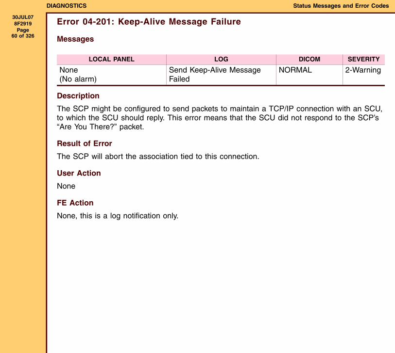
Error 04-201: Keep-Alive Message Failure
Messages
Description
The SCP might be configured to send packets to maintain a TCP/IP connection with an SCU, to which the SCU should reply. This error means that the SCU did not respond to the SCP’s “Are You There?” packet.
Result of Error
The SCP will abort the association tied to this connection.
User Action
None
FE Action
None, this is a log notification only.
LOCAL PANEL LOG DICOM SEVERITY
None (No alarm)
Send Keep-Alive Message Failed
NORMAL 2-Warning
DIAGNOSTICS Status Messages and Error Codes
30JUL078F2919 Page
61 of 326
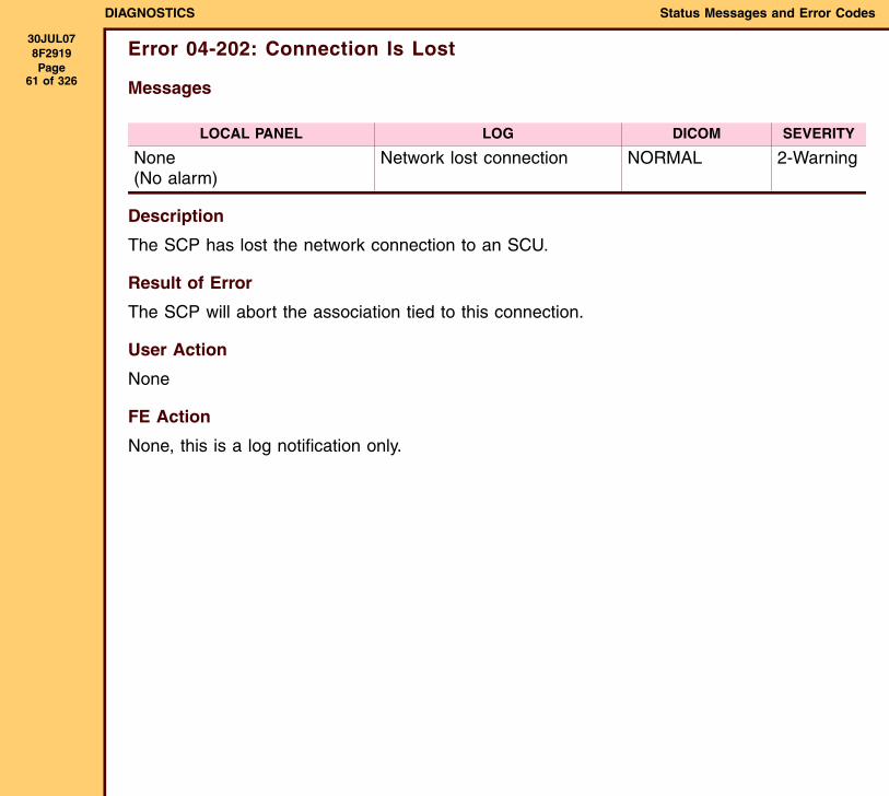
Error 04-202: Connection Is Lost
Messages
Description
The SCP has lost the network connection to an SCU.
Result of Error
The SCP will abort the association tied to this connection.
User Action
None
FE Action
None, this is a log notification only.
LOCAL PANEL LOG DICOM SEVERITY
None(No alarm)
Network lost connection NORMAL 2-Warning
DIAGNOSTICS Status Messages and Error Codes
30JUL078F2919 Page
62 of 326
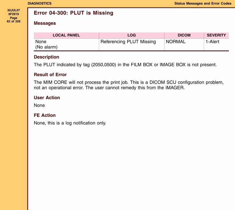
Error 04-300: PLUT is Missing
Messages
Description
The PLUT indicated by tag (2050,0500) in the FILM BOX or IMAGE BOX is not present.
Result of Error
The MIM CORE will not process the print job. This is a DICOM SCU configuration problem, not an operational error. The user cannot remedy this from the IMAGER.
User Action
None
FE Action
None, this is a log notification only.
LOCAL PANEL LOG DICOM SEVERITY
None(No alarm)
Referencing PLUT Missing NORMAL 1-Alert
DIAGNOSTICS Status Messages and Error Codes
30JUL078F2919 Page
63 of 326
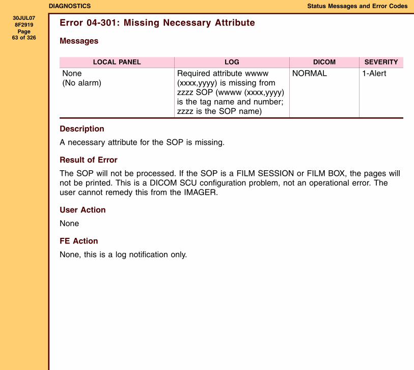
Error 04-301: Missing Necessary Attribute
Messages
Description
A necessary attribute for the SOP is missing.
Result of Error
The SOP will not be processed. If the SOP is a FILM SESSION or FILM BOX, the pages will not be printed. This is a DICOM SCU configuration problem, not an operational error. The user cannot remedy this from the IMAGER.
User Action
None
FE Action
None, this is a log notification only.
LOCAL PANEL LOG DICOM SEVERITY
None(No alarm)
Required attribute wwww (xxxx,yyyy) is missing from zzzz SOP (wwww (xxxx,yyyy) is the tag name and number; zzzz is the SOP name)
NORMAL 1-Alert
DIAGNOSTICS Status Messages and Error Codes
30JUL078F2919 Page
64 of 326
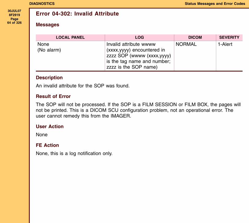
Error 04-302: Invalid Attribute
Messages
Description
An invalid attribute for the SOP was found.
Result of Error
The SOP will not be processed. If the SOP is a FILM SESSION or FILM BOX, the pages will not be printed. This is a DICOM SCU configuration problem, not an operational error. The user cannot remedy this from the IMAGER.
User Action
None
FE Action
None, this is a log notification only.
LOCAL PANEL LOG DICOM SEVERITY
None(No alarm)
Invalid attribute wwww (xxxx,yyyy) encountered in zzzz SOP (wwww (xxxx,yyyy) is the tag name and number; zzzz is the SOP name)
NORMAL 1-Alert
DIAGNOSTICS Status Messages and Error Codes
30JUL078F2919 Page
65 of 326
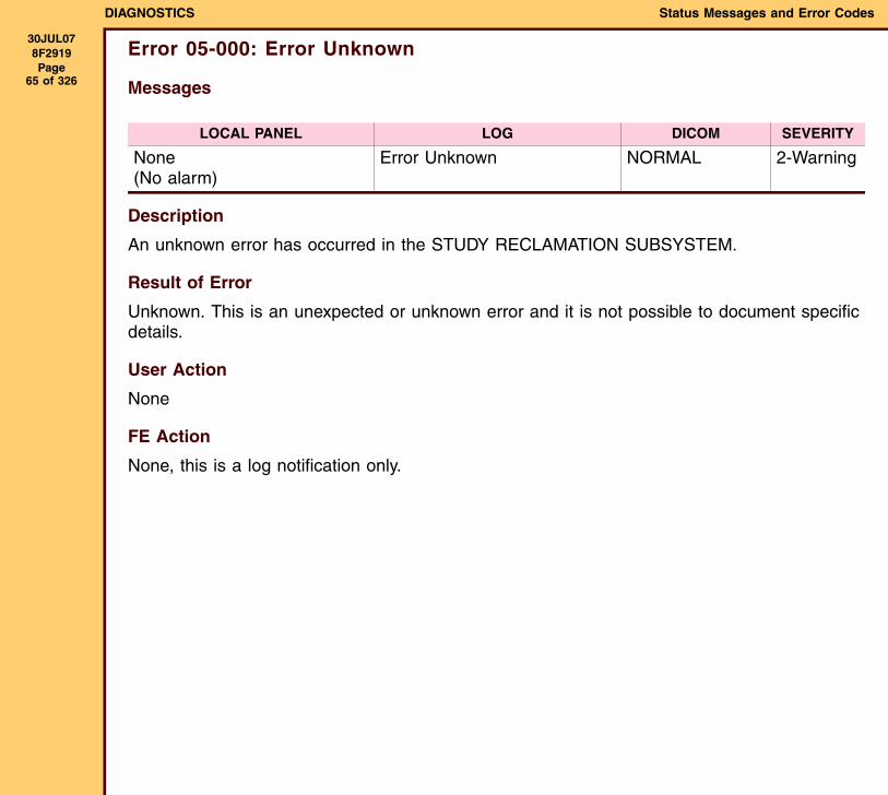
Error 05-000: Error Unknown
Messages
Description
An unknown error has occurred in the STUDY RECLAMATION SUBSYSTEM.
Result of Error
Unknown. This is an unexpected or unknown error and it is not possible to document specific details.
User Action
None
FE Action
None, this is a log notification only.
LOCAL PANEL LOG DICOM SEVERITY
None(No alarm)
Error Unknown NORMAL 2-Warning
DIAGNOSTICS Status Messages and Error Codes
30JUL078F2919 Page
66 of 326
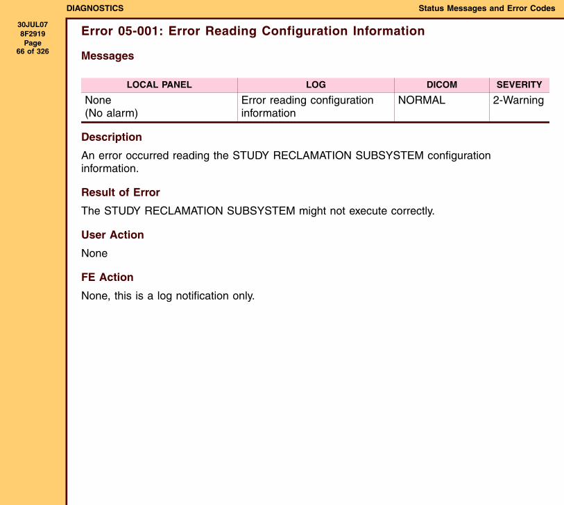
Error 05-001: Error Reading Configuration Information
Messages
Description
An error occurred reading the STUDY RECLAMATION SUBSYSTEM configuration information.
Result of Error
The STUDY RECLAMATION SUBSYSTEM might not execute correctly.
User Action
None
FE Action
None, this is a log notification only.
LOCAL PANEL LOG DICOM SEVERITY
None(No alarm)
Error reading configuration information
NORMAL 2-Warning
DIAGNOSTICS Status Messages and Error Codes
30JUL078F2919 Page
67 of 326
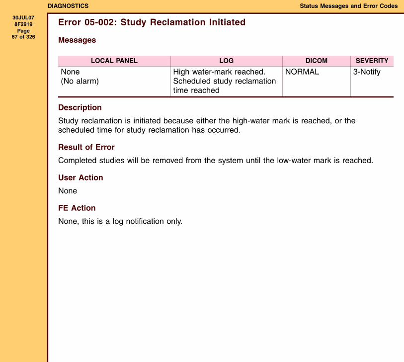
Error 05-002: Study Reclamation Initiated
Messages
Description
Study reclamation is initiated because either the high-water mark is reached, or the scheduled time for study reclamation has occurred.
Result of Error
Completed studies will be removed from the system until the low-water mark is reached.
User Action
None
FE Action
None, this is a log notification only.
LOCAL PANEL LOG DICOM SEVERITY
None(No alarm)
High water-mark reached. Scheduled study reclamation time reached
NORMAL 3-Notify
DIAGNOSTICS Status Messages and Error Codes
30JUL078F2919 Page
68 of 326
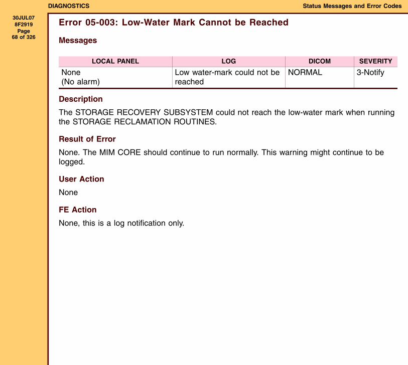
Error 05-003: Low-Water Mark Cannot be Reached
Messages
Description
The STORAGE RECOVERY SUBSYSTEM could not reach the low-water mark when running the STORAGE RECLAMATION ROUTINES.
Result of Error
None. The MIM CORE should continue to run normally. This warning might continue to be logged.
User Action
None
FE Action
None, this is a log notification only.
LOCAL PANEL LOG DICOM SEVERITY
None(No alarm)
Low water-mark could not be reached
NORMAL 3-Notify
DIAGNOSTICS Status Messages and Error Codes
30JUL078F2919 Page
69 of 326
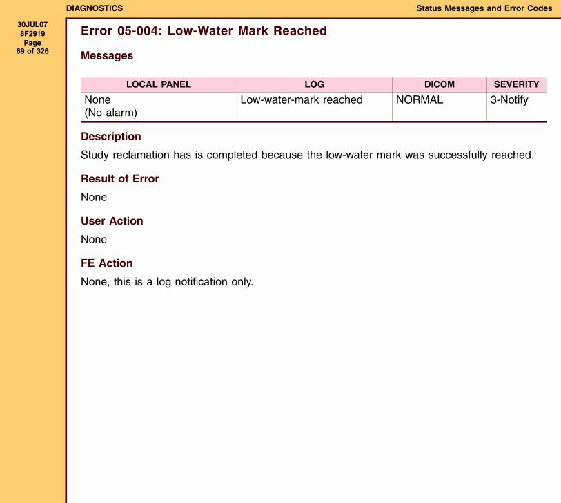
Error 05-004: Low-Water Mark Reached
Messages
Description
Study reclamation has is completed because the low-water mark was successfully reached.
Result of Error
None
User Action
None
FE Action
None, this is a log notification only.
LOCAL PANEL LOG DICOM SEVERITY
None(No alarm)
Low-water-mark reached NORMAL 3-Notify
DIAGNOSTICS Status Messages and Error Codes
30JUL078F2919 Page
70 of 326
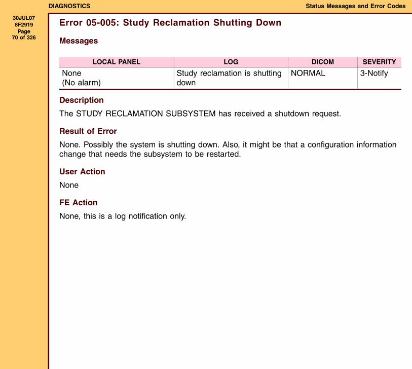
Error 05-005: Study Reclamation Shutting Down
Messages
Description
The STUDY RECLAMATION SUBSYSTEM has received a shutdown request.
Result of Error
None. Possibly the system is shutting down. Also, it might be that a configuration information change that needs the subsystem to be restarted.
User Action
None
FE Action
None, this is a log notification only.
LOCAL PANEL LOG DICOM SEVERITY
None(No alarm)
Study reclamation is shutting down
NORMAL 3-Notify
DIAGNOSTICS Status Messages and Error Codes
30JUL078F2919 Page
71 of 326
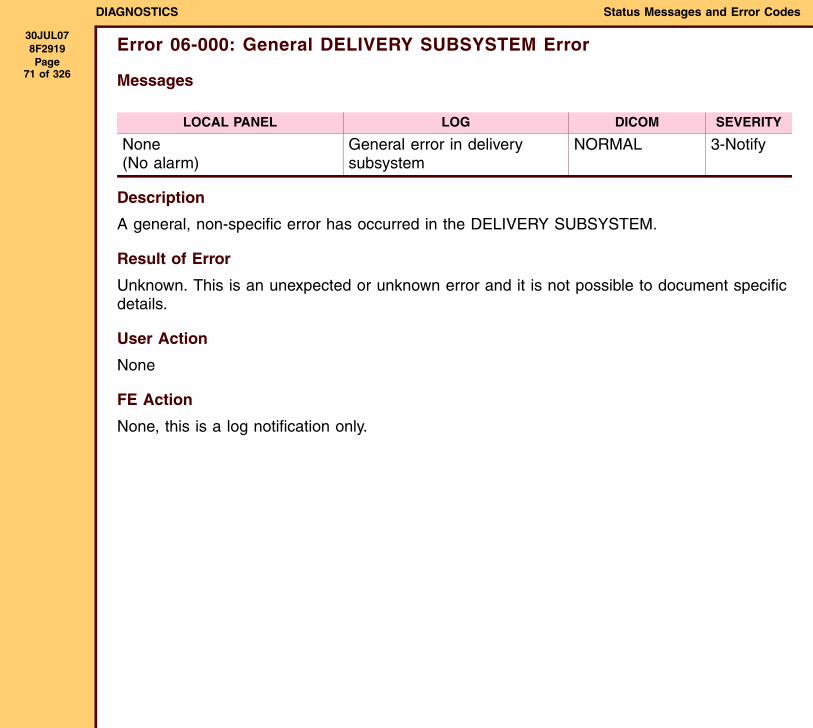
Error 06-000: General DELIVERY SUBSYSTEM Error
Messages
Description
A general, non-specific error has occurred in the DELIVERY SUBSYSTEM.
Result of Error
Unknown. This is an unexpected or unknown error and it is not possible to document specific details.
User Action
None
FE Action
None, this is a log notification only.
LOCAL PANEL LOG DICOM SEVERITY
None(No alarm)
General error in delivery subsystem
NORMAL 3-Notify
DIAGNOSTICS Status Messages and Error Codes
30JUL078F2919 Page
72 of 326
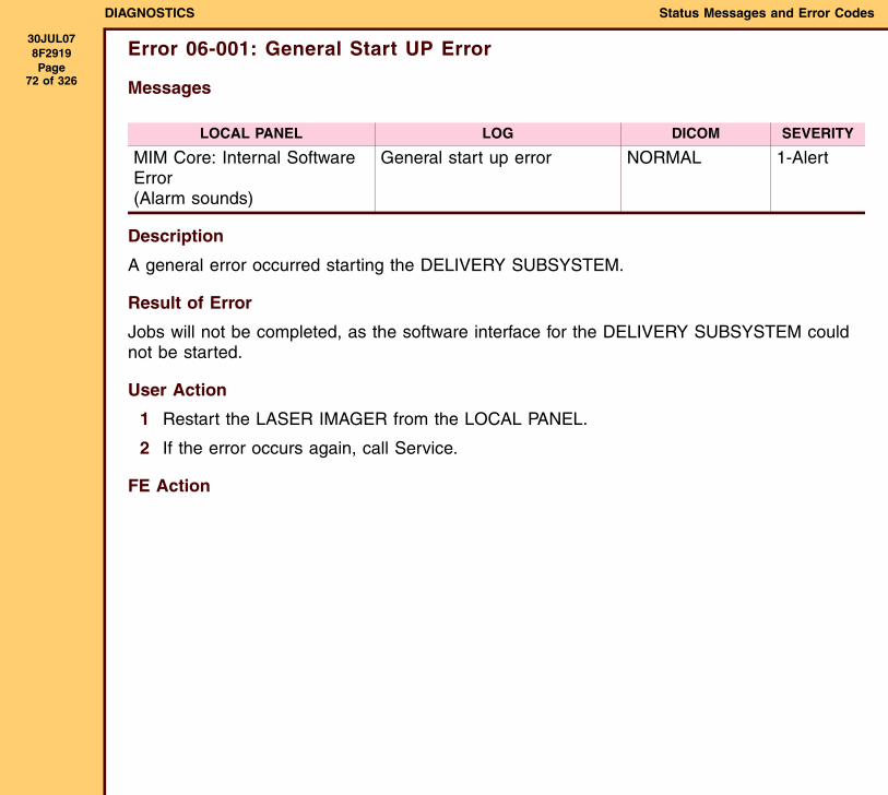
Error 06-001: General Start UP Error
Messages
Description
A general error occurred starting the DELIVERY SUBSYSTEM.
Result of Error
Jobs will not be completed, as the software interface for the DELIVERY SUBSYSTEM could not be started.
User Action
1 Restart the LASER IMAGER from the LOCAL PANEL.
2 If the error occurs again, call Service.
FE Action
LOCAL PANEL LOG DICOM SEVERITY
MIM Core: Internal Software Error(Alarm sounds)
General start up error NORMAL 1-Alert
DIAGNOSTICS Status Messages and Error Codes
30JUL078F2919 Page
73 of 326
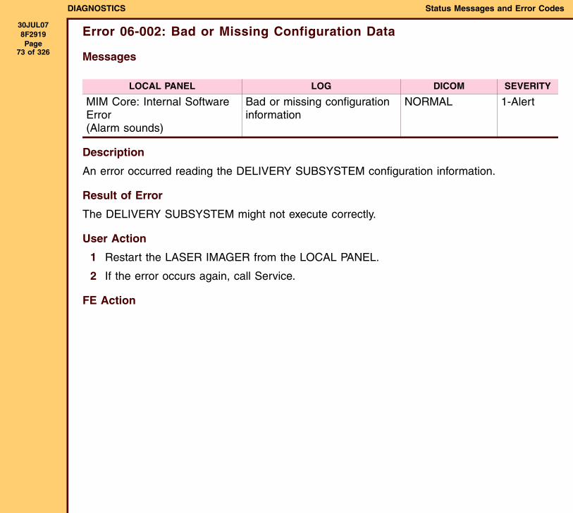
Error 06-002: Bad or Missing Configuration Data
Messages
Description
An error occurred reading the DELIVERY SUBSYSTEM configuration information.
Result of Error
The DELIVERY SUBSYSTEM might not execute correctly.
User Action
1 Restart the LASER IMAGER from the LOCAL PANEL.
2 If the error occurs again, call Service.
FE Action
LOCAL PANEL LOG DICOM SEVERITY
MIM Core: Internal Software Error(Alarm sounds)
Bad or missing configuration information
NORMAL 1-Alert
DIAGNOSTICS Status Messages and Error Codes
30JUL078F2919 Page
74 of 326
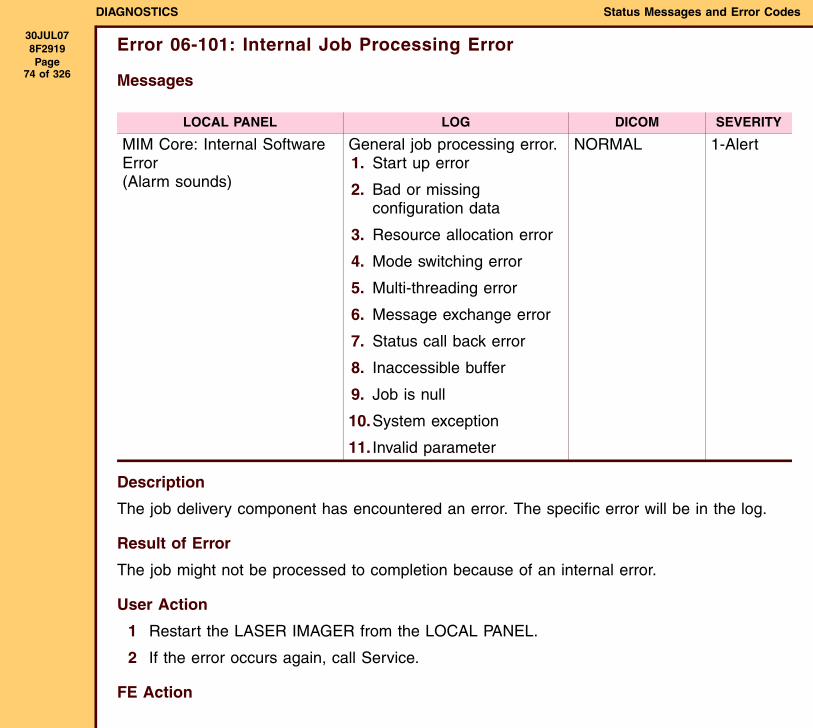
Error 06-101: Internal Job Processing Error
Messages
Description
The job delivery component has encountered an error. The specific error will be in the log.
Result of Error
The job might not be processed to completion because of an internal error.
User Action
1 Restart the LASER IMAGER from the LOCAL PANEL.
2 If the error occurs again, call Service.
FE Action
LOCAL PANEL LOG DICOM SEVERITY
MIM Core: Internal Software Error(Alarm sounds)
General job processing error.1. Start up error
2. Bad or missing configuration data
3. Resource allocation error
4. Mode switching error
5. Multi-threading error
6. Message exchange error
7. Status call back error
8. Inaccessible buffer
9. Job is null
10.System exception
11. Invalid parameter
NORMAL 1-Alert
DIAGNOSTICS Status Messages and Error Codes
30JUL078F2919 Page
75 of 326
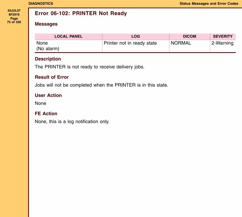
Error 06-102: PRINTER Not Ready
Messages
Description
The PRINTER is not ready to receive delivery jobs.
Result of Error
Jobs will not be completed when the PRINTER is in this state.
User Action
None
FE Action
None, this is a log notification only.
LOCAL PANEL LOG DICOM SEVERITY
None(No alarm)
Printer not in ready state NORMAL 2-Warning
DIAGNOSTICS Status Messages and Error Codes
30JUL078F2919 Page
76 of 326
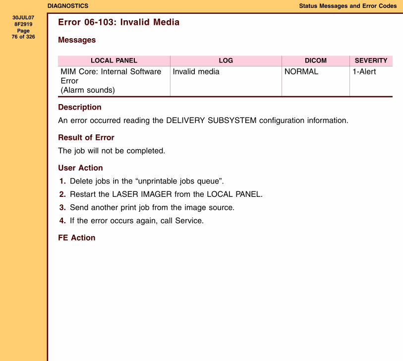
Error 06-103: Invalid Media
Messages
Description
An error occurred reading the DELIVERY SUBSYSTEM configuration information.
Result of Error
The job will not be completed.
User Action
1. Delete jobs in the “unprintable jobs queue”.
2. Restart the LASER IMAGER from the LOCAL PANEL.
3. Send another print job from the image source.
4. If the error occurs again, call Service.
FE Action
LOCAL PANEL LOG DICOM SEVERITY
MIM Core: Internal Software Error(Alarm sounds)
Invalid media NORMAL 1-Alert
DIAGNOSTICS Status Messages and Error Codes
30JUL078F2919 Page
77 of 326
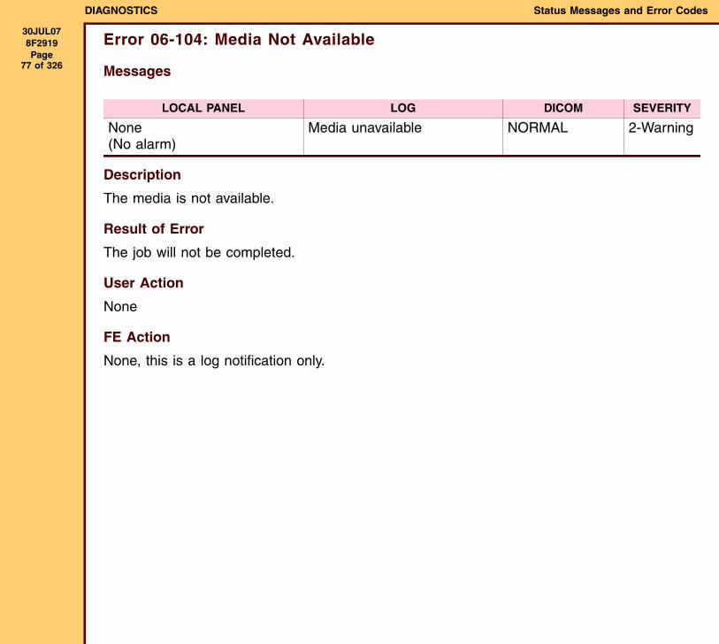
Error 06-104: Media Not Available
Messages
Description
The media is not available.
Result of Error
The job will not be completed.
User Action
None
FE Action
None, this is a log notification only.
LOCAL PANEL LOG DICOM SEVERITY
None(No alarm)
Media unavailable NORMAL 2-Warning
DIAGNOSTICS Status Messages and Error Codes
30JUL078F2919 Page
78 of 326
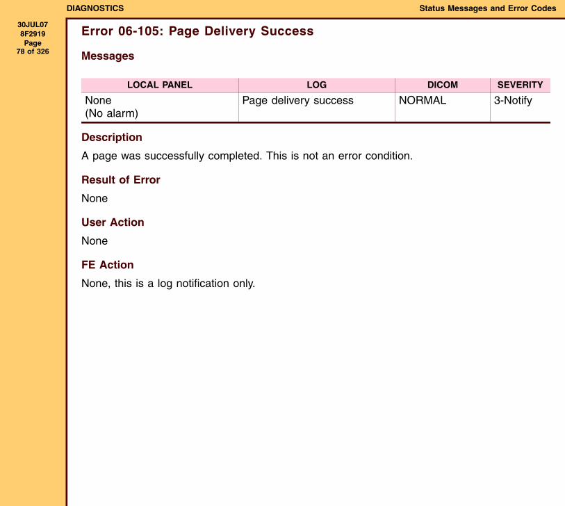
Error 06-105: Page Delivery Success
Messages
Description
A page was successfully completed. This is not an error condition.
Result of Error
None
User Action
None
FE Action
None, this is a log notification only.
LOCAL PANEL LOG DICOM SEVERITY
None(No alarm)
Page delivery success NORMAL 3-Notify
DIAGNOSTICS Status Messages and Error Codes
30JUL078F2919 Page
79 of 326
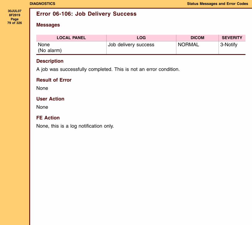
Error 06-106: Job Delivery Success
Messages
Description
A job was successfully completed. This is not an error condition.
Result of Error
None
User Action
None
FE Action
None, this is a log notification only.
LOCAL PANEL LOG DICOM SEVERITY
None(No alarm)
Job delivery success NORMAL 3-Notify
DIAGNOSTICS Status Messages and Error Codes
30JUL078F2919 Page
80 of 326
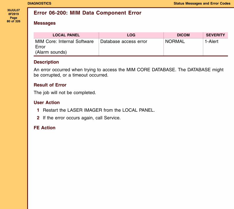
Error 06-200: MIM Data Component Error
Messages
Description
An error occurred when trying to access the MIM CORE DATABASE. The DATABASE might be corrupted, or a timeout occurred.
Result of Error
The job will not be completed.
User Action
1 Restart the LASER IMAGER from the LOCAL PANEL.
2 If the error occurs again, call Service.
FE Action
LOCAL PANEL LOG DICOM SEVERITY
MIM Core: Internal Software Error(Alarm sounds)
Database access error NORMAL 1-Alert
DIAGNOSTICS Status Messages and Error Codes
30JUL078F2919 Page
81 of 326
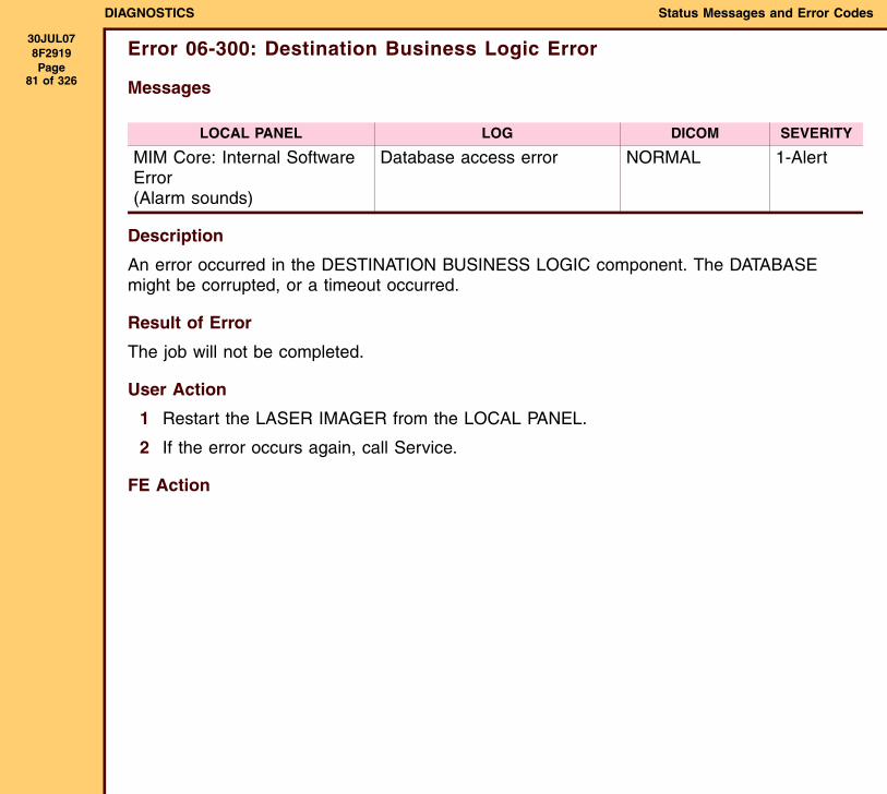
Error 06-300: Destination Business Logic Error
Messages
Description
An error occurred in the DESTINATION BUSINESS LOGIC component. The DATABASE might be corrupted, or a timeout occurred.
Result of Error
The job will not be completed.
User Action
1 Restart the LASER IMAGER from the LOCAL PANEL.
2 If the error occurs again, call Service.
FE Action
LOCAL PANEL LOG DICOM SEVERITY
MIM Core: Internal Software Error(Alarm sounds)
Database access error NORMAL 1-Alert
DIAGNOSTICS Status Messages and Error Codes
30JUL078F2919 Page
82 of 326
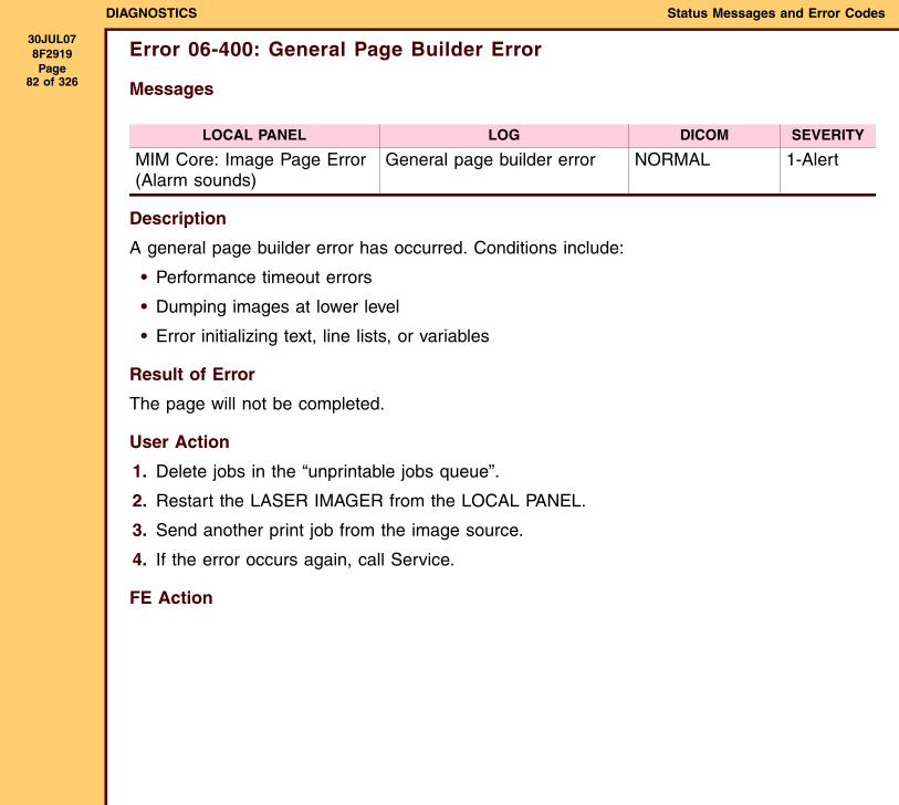
Error 06-400: General Page Builder Error
Messages
Description
A general page builder error has occurred. Conditions include:
• Performance timeout errors
• Dumping images at lower level
• Error initializing text, line lists, or variables
Result of Error
The page will not be completed.
User Action
1. Delete jobs in the “unprintable jobs queue”.
2. Restart the LASER IMAGER from the LOCAL PANEL.
3. Send another print job from the image source.
4. If the error occurs again, call Service.
FE Action
LOCAL PANEL LOG DICOM SEVERITY
MIM Core: Image Page Error(Alarm sounds)
General page builder error NORMAL 1-Alert
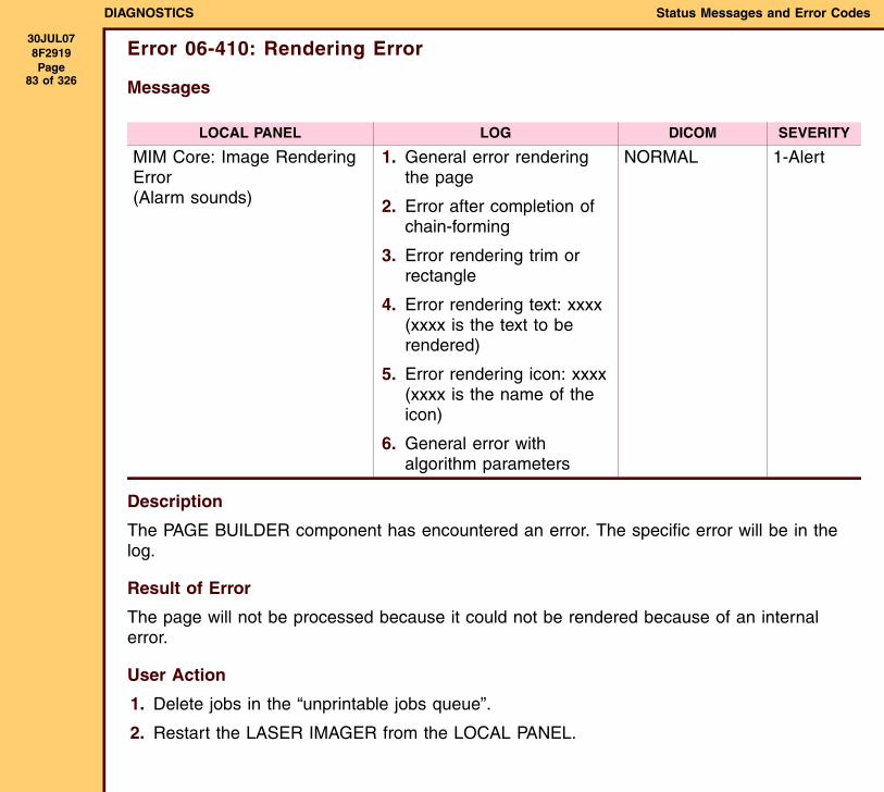
DIAGNOSTICS Status Messages and Error Codes
30JUL078F2919 Page
83 of 326
Error 06-410: Rendering Error
Messages
Description
The PAGE BUILDER component has encountered an error. The specific error will be in the log.
Result of Error
The page will not be processed because it could not be rendered because of an internal error.
User Action
1. Delete jobs in the “unprintable jobs queue”.
2. Restart the LASER IMAGER from the LOCAL PANEL.
LOCAL PANEL LOG DICOM SEVERITY
MIM Core: Image Rendering Error(Alarm sounds)
1. General error rendering the page
2. Error after completion of chain-forming
3. Error rendering trim or rectangle
4. Error rendering text: xxxx (xxxx is the text to be rendered)
5. Error rendering icon: xxxx (xxxx is the name of the icon)
6. General error with algorithm parameters
NORMAL 1-Alert
DIAGNOSTICS Status Messages and Error Codes
30JUL078F2919 Page
84 of 326
3. Send another print job from the image source.
4. If the error occurs again, call Service.
FE Action
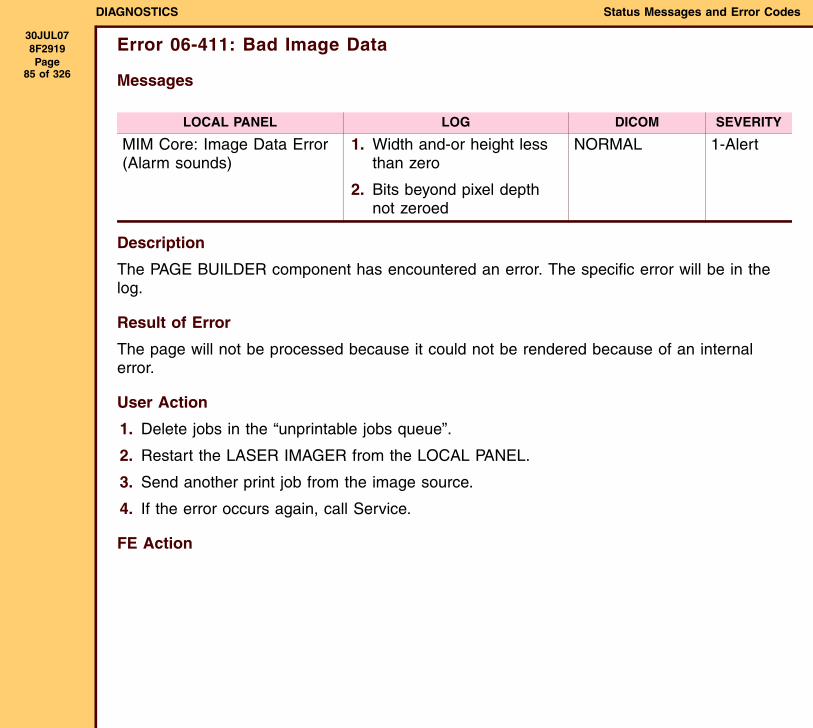
DIAGNOSTICS Status Messages and Error Codes
30JUL078F2919 Page
85 of 326
Error 06-411: Bad Image Data
Messages
Description
The PAGE BUILDER component has encountered an error. The specific error will be in the log.
Result of Error
The page will not be processed because it could not be rendered because of an internal error.
User Action
1. Delete jobs in the “unprintable jobs queue”.
2. Restart the LASER IMAGER from the LOCAL PANEL.
3. Send another print job from the image source.
4. If the error occurs again, call Service.
FE Action
LOCAL PANEL LOG DICOM SEVERITY
MIM Core: Image Data Error(Alarm sounds)
1. Width and-or height less than zero
2. Bits beyond pixel depth not zeroed
NORMAL 1-Alert
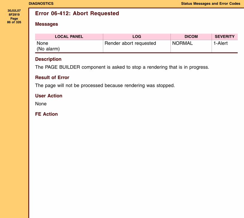
DIAGNOSTICS Status Messages and Error Codes
30JUL078F2919 Page
86 of 326
Error 06-412: Abort Requested
Messages
Description
The PAGE BUILDER component is asked to stop a rendering that is in progress.
Result of Error
The page will not be processed because rendering was stopped.
User Action
None
FE Action
LOCAL PANEL LOG DICOM SEVERITY
None(No alarm)
Render abort requested NORMAL 1-Alert
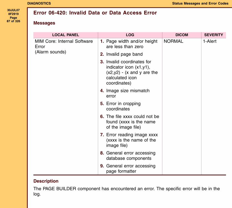
DIAGNOSTICS Status Messages and Error Codes
30JUL078F2919 Page
87 of 326
Error 06-420: Invalid Data or Data Access Error
Messages
Description
The PAGE BUILDER component has encountered an error. The specific error will be in the log.
LOCAL PANEL LOG DICOM SEVERITY
MIM Core: Internal Software Error(Alarm sounds)
1. Page width and/or height are less than zero
2. Invalid page band
3. Invalid coordinates for indicator icon (x1,y1), (x2,y2) - (x and y are the calculated icon coordinates)
4. Image size mismatch error
5. Error in cropping coordinates
6. The file xxxx could not be found (xxxx is the name of the image file)
7. Error reading image xxxx (xxxx is the name of the image file)
8. General error accessing database components
9. General error accessing page formatter
NORMAL 1-Alert
DIAGNOSTICS Status Messages and Error Codes
30JUL078F2919 Page
88 of 326
Result of Error
The page will not be processed because it could not be rendered because of an internal error.
User Action
1. Delete jobs in the “unprintable jobs queue”.
2. Restart the LASER IMAGER from the LOCAL PANEL.
3. Send another print job from the image source.
4. If the error occurs again, call Service.
FE Action
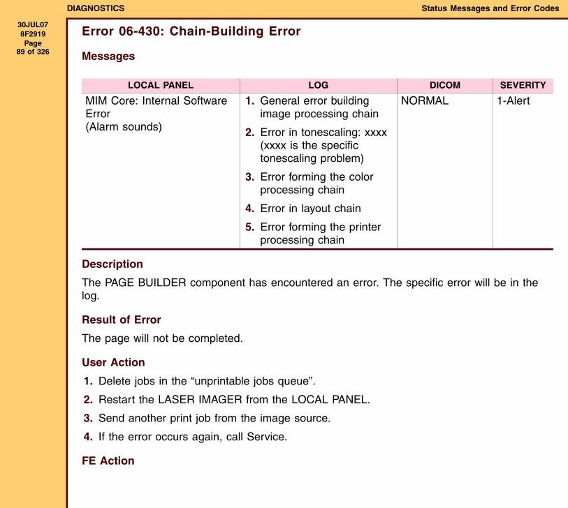
DIAGNOSTICS Status Messages and Error Codes
30JUL078F2919 Page
89 of 326
Error 06-430: Chain-Building Error
Messages
Description
The PAGE BUILDER component has encountered an error. The specific error will be in the log.
Result of Error
The page will not be completed.
User Action
1. Delete jobs in the “unprintable jobs queue”.
2. Restart the LASER IMAGER from the LOCAL PANEL.
3. Send another print job from the image source.
4. If the error occurs again, call Service.
FE Action
LOCAL PANEL LOG DICOM SEVERITY
MIM Core: Internal Software Error(Alarm sounds)
1. General error building image processing chain
2. Error in tonescaling: xxxx (xxxx is the specific tonescaling problem)
3. Error forming the color processing chain
4. Error in layout chain
5. Error forming the printer processing chain
NORMAL 1-Alert
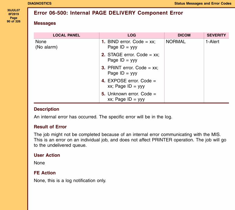
DIAGNOSTICS Status Messages and Error Codes
30JUL078F2919 Page
90 of 326
Error 06-500: Internal PAGE DELIVERY Component Error
Messages
Description
An internal error has occurred. The specific error will be in the log.
Result of Error
The job might not be completed because of an internal error communicating with the MIS. This is an error on an individual job, and does not affect PRINTER operation. The job will go to the undelivered queue.
User Action
None
FE Action
None, this is a log notification only.
LOCAL PANEL LOG DICOM SEVERITY
None(No alarm)
1. BIND error. Code = xx; Page ID = yyy
2. STAGE error. Code = xx; Page ID = yyy
3. PRINT error. Code = xx; Page ID = yyy
4. EXPOSE error. Code = xx; Page ID = yyy
5. Unknown error. Code = xx; Page ID = yyy
NORMAL 1-Alert
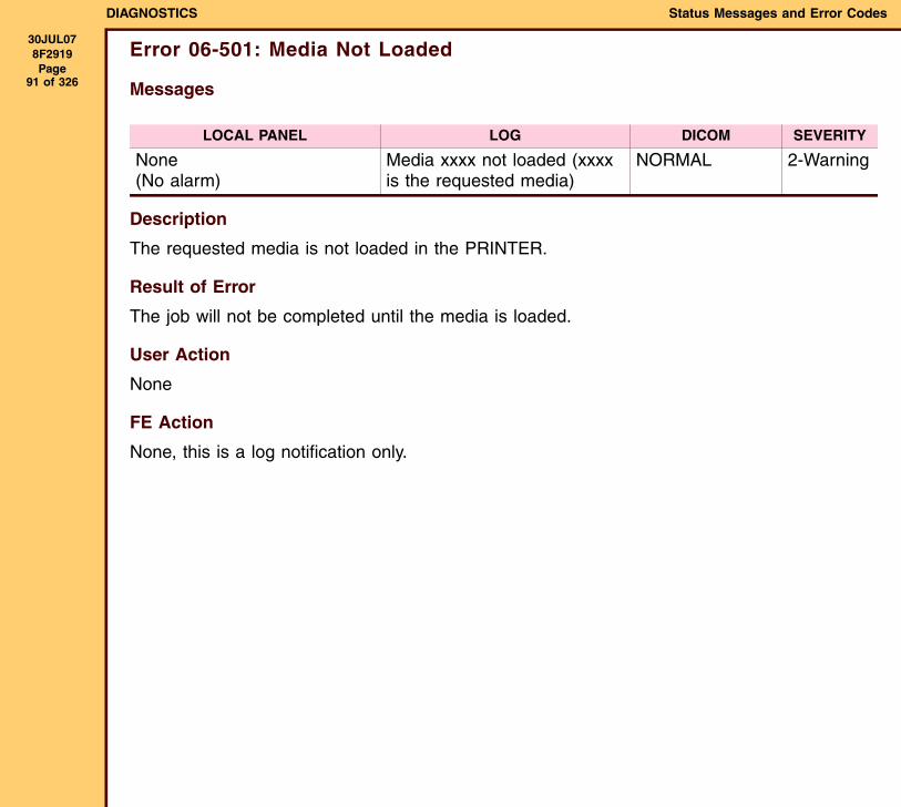
DIAGNOSTICS Status Messages and Error Codes
30JUL078F2919 Page
91 of 326
Error 06-501: Media Not Loaded
Messages
Description
The requested media is not loaded in the PRINTER.
Result of Error
The job will not be completed until the media is loaded.
User Action
None
FE Action
None, this is a log notification only.
LOCAL PANEL LOG DICOM SEVERITY
None(No alarm)
Media xxxx not loaded (xxxx is the requested media)
NORMAL 2-Warning
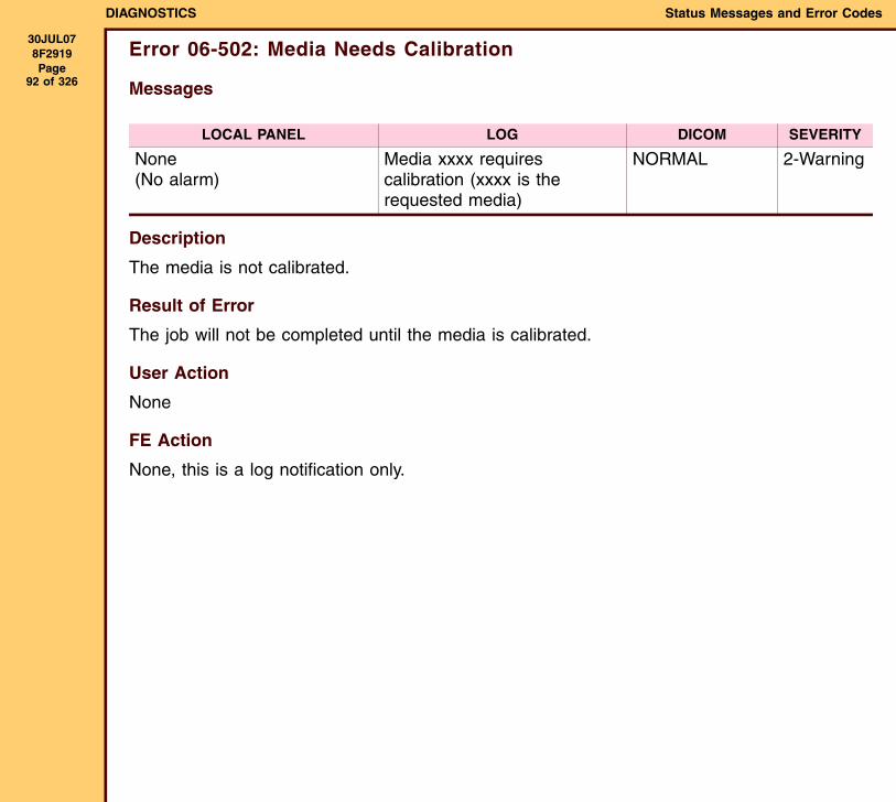
DIAGNOSTICS Status Messages and Error Codes
30JUL078F2919 Page
92 of 326
Error 06-502: Media Needs Calibration
Messages
Description
The media is not calibrated.
Result of Error
The job will not be completed until the media is calibrated.
User Action
None
FE Action
None, this is a log notification only.
LOCAL PANEL LOG DICOM SEVERITY
None(No alarm)
Media xxxx requires calibration (xxxx is the requested media)
NORMAL 2-Warning
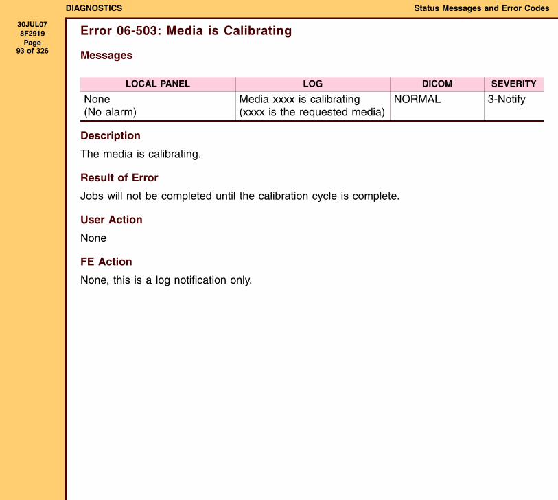
DIAGNOSTICS Status Messages and Error Codes
30JUL078F2919 Page
93 of 326
Error 06-503: Media is Calibrating
Messages
Description
The media is calibrating.
Result of Error
Jobs will not be completed until the calibration cycle is complete.
User Action
None
FE Action
None, this is a log notification only.
LOCAL PANEL LOG DICOM SEVERITY
None(No alarm)
Media xxxx is calibrating (xxxx is the requested media)
NORMAL 3-Notify
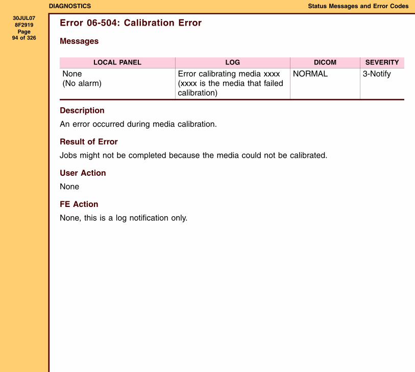
DIAGNOSTICS Status Messages and Error Codes
30JUL078F2919 Page
94 of 326
Error 06-504: Calibration Error
Messages
Description
An error occurred during media calibration.
Result of Error
Jobs might not be completed because the media could not be calibrated.
User Action
None
FE Action
None, this is a log notification only.
LOCAL PANEL LOG DICOM SEVERITY
None(No alarm)
Error calibrating media xxxx (xxxx is the media that failed calibration)
NORMAL 3-Notify
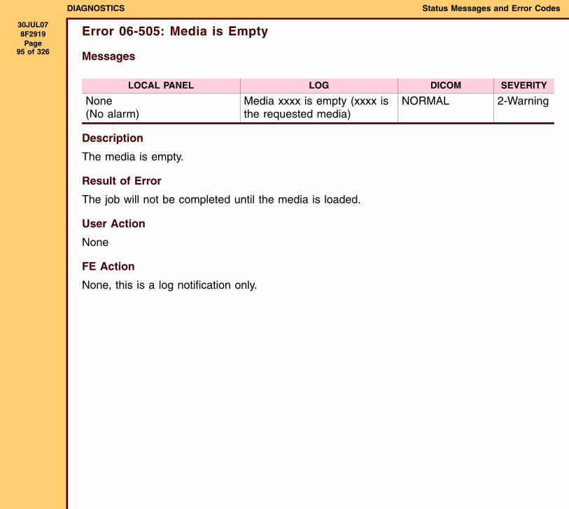
DIAGNOSTICS Status Messages and Error Codes
30JUL078F2919 Page
95 of 326
Error 06-505: Media is Empty
Messages
Description
The media is empty.
Result of Error
The job will not be completed until the media is loaded.
User Action
None
FE Action
None, this is a log notification only.
LOCAL PANEL LOG DICOM SEVERITY
None(No alarm)
Media xxxx is empty (xxxx is the requested media)
NORMAL 2-Warning
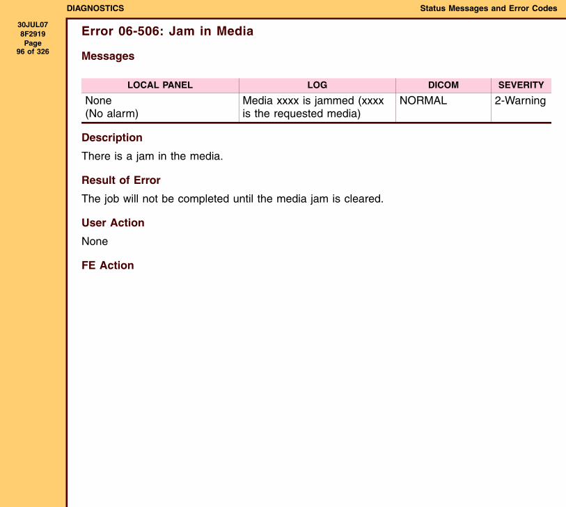
DIAGNOSTICS Status Messages and Error Codes
30JUL078F2919 Page
96 of 326
Error 06-506: Jam in Media
Messages
Description
There is a jam in the media.
Result of Error
The job will not be completed until the media jam is cleared.
User Action
None
FE Action
LOCAL PANEL LOG DICOM SEVERITY
None(No alarm)
Media xxxx is jammed (xxxx is the requested media)
NORMAL 2-Warning
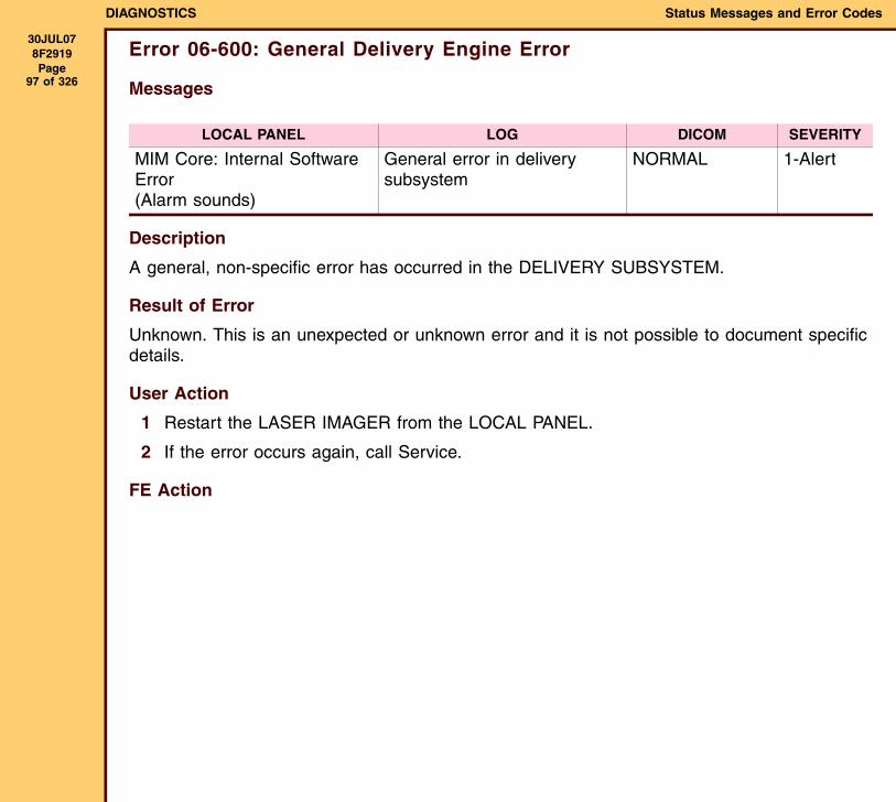
DIAGNOSTICS Status Messages and Error Codes
30JUL078F2919 Page
97 of 326
Error 06-600: General Delivery Engine Error
Messages
Description
A general, non-specific error has occurred in the DELIVERY SUBSYSTEM.
Result of Error
Unknown. This is an unexpected or unknown error and it is not possible to document specific details.
User Action
1 Restart the LASER IMAGER from the LOCAL PANEL.
2 If the error occurs again, call Service.
FE Action
LOCAL PANEL LOG DICOM SEVERITY
MIM Core: Internal Software Error(Alarm sounds)
General error in delivery subsystem
NORMAL 1-Alert
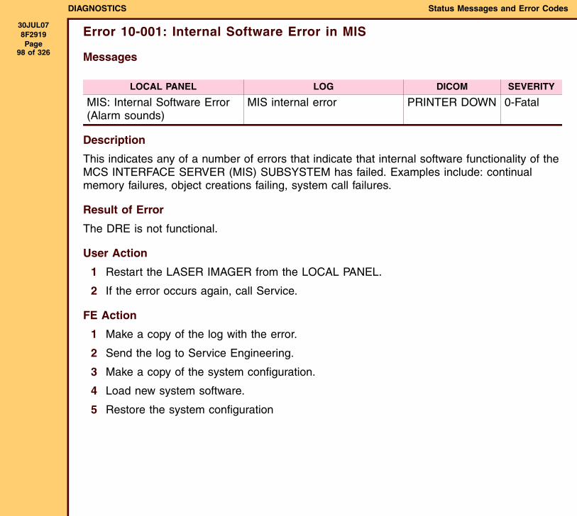
DIAGNOSTICS Status Messages and Error Codes
30JUL078F2919 Page
98 of 326
Error 10-001: Internal Software Error in MIS
Messages
Description
This indicates any of a number of errors that indicate that internal software functionality of the MCS INTERFACE SERVER (MIS) SUBSYSTEM has failed. Examples include: continual memory failures, object creations failing, system call failures.
Result of Error
The DRE is not functional.
User Action
1 Restart the LASER IMAGER from the LOCAL PANEL.
2 If the error occurs again, call Service.
FE Action
1 Make a copy of the log with the error.
2 Send the log to Service Engineering.
3 Make a copy of the system configuration.
4 Load new system software.
5 Restore the system configuration
LOCAL PANEL LOG DICOM SEVERITY
MIS: Internal Software Error (Alarm sounds)
MIS internal error PRINTER DOWN 0-Fatal
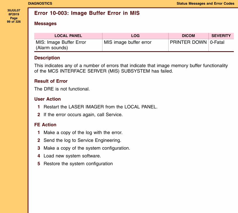
DIAGNOSTICS Status Messages and Error Codes
30JUL078F2919 Page
99 of 326
Error 10-003: Image Buffer Error in MIS
Messages
Description
This indicates any of a number of errors that indicate that image memory buffer functionality of the MCS INTERFACE SERVER (MIS) SUBSYSTEM has failed.
Result of Error
The DRE is not functional.
User Action
1 Restart the LASER IMAGER from the LOCAL PANEL.
2 If the error occurs again, call Service.
FE Action
1 Make a copy of the log with the error.
2 Send the log to Service Engineering.
3 Make a copy of the system configuration.
4 Load new system software.
5 Restore the system configuration
LOCAL PANEL LOG DICOM SEVERITY
MIS: Image Buffer Error (Alarm sounds)
MIS image buffer error PRINTER DOWN 0-Fatal
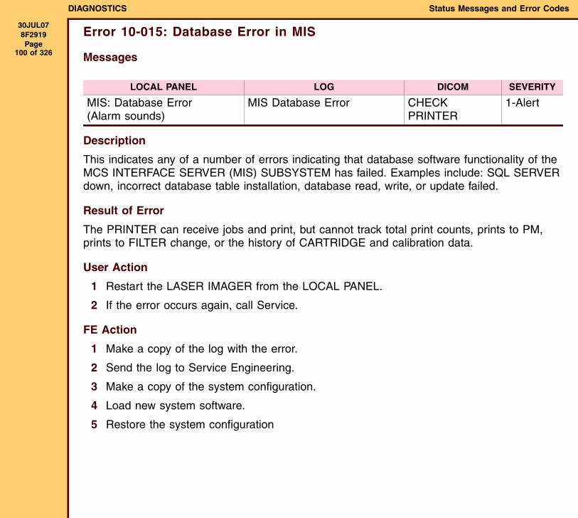
DIAGNOSTICS Status Messages and Error Codes
30JUL078F2919 Page
100 of 326
Error 10-015: Database Error in MIS
Messages
Description
This indicates any of a number of errors indicating that database software functionality of the MCS INTERFACE SERVER (MIS) SUBSYSTEM has failed. Examples include: SQL SERVER down, incorrect database table installation, database read, write, or update failed.
Result of Error
The PRINTER can receive jobs and print, but cannot track total print counts, prints to PM, prints to FILTER change, or the history of CARTRIDGE and calibration data.
User Action
1 Restart the LASER IMAGER from the LOCAL PANEL.
2 If the error occurs again, call Service.
FE Action
1 Make a copy of the log with the error.
2 Send the log to Service Engineering.
3 Make a copy of the system configuration.
4 Load new system software.
5 Restore the system configuration
LOCAL PANEL LOG DICOM SEVERITY
MIS: Database Error (Alarm sounds)
MIS Database Error CHECK PRINTER
1-Alert
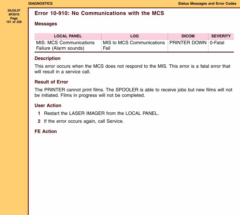
DIAGNOSTICS Status Messages and Error Codes
30JUL078F2919 Page
101 of 326
Error 10-910: No Communications with the MCS
Messages
Description
This error occurs when the MCS does not respond to the MIS. This error is a fatal error that will result in a service call.
Result of Error
The PRINTER cannot print films. The SPOOLER is able to receive jobs but new films will not be initiated. Films in progress will not be completed.
User Action
1 Restart the LASER IMAGER from the LOCAL PANEL.
2 If the error occurs again, call Service.
FE Action
LOCAL PANEL LOG DICOM SEVERITY
MIS: MCS Communications Failure (Alarm sounds)
MIS to MCS Communications Fail
PRINTER DOWN 0-Fatal
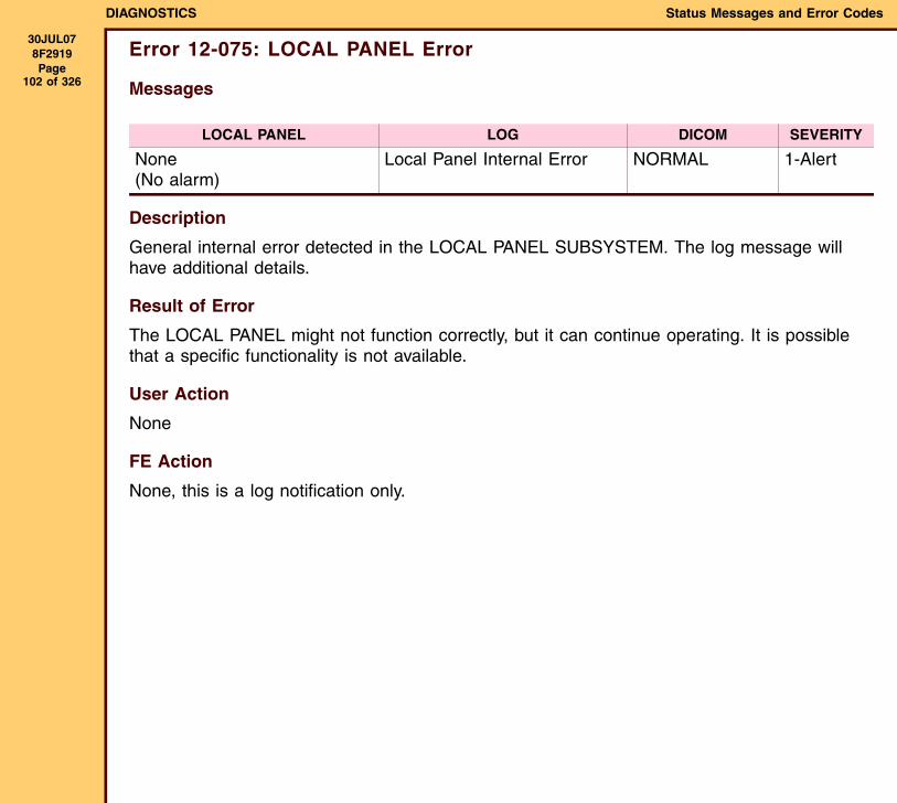
DIAGNOSTICS Status Messages and Error Codes
30JUL078F2919 Page
102 of 326
Error 12-075: LOCAL PANEL Error
Messages
Description
General internal error detected in the LOCAL PANEL SUBSYSTEM. The log message will have additional details.
Result of Error
The LOCAL PANEL might not function correctly, but it can continue operating. It is possible that a specific functionality is not available.
User Action
None
FE Action
None, this is a log notification only.
LOCAL PANEL LOG DICOM SEVERITY
None (No alarm)
Local Panel Internal Error NORMAL 1-Alert
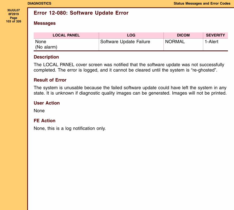
DIAGNOSTICS Status Messages and Error Codes
30JUL078F2919 Page
103 of 326
Error 12-080: Software Update Error
Messages
Description
The LOCAL PANEL cover screen was notified that the software update was not successfully completed. The error is logged, and it cannot be cleared until the system is “re-ghosted”.
Result of Error
The system is unusable because the failed software update could have left the system in any state. It is unknown if diagnostic quality images can be generated. Images will not be printed.
User Action
None
FE Action
None, this is a log notification only.
LOCAL PANEL LOG DICOM SEVERITY
None (No alarm)
Software Update Failure NORMAL 1-Alert
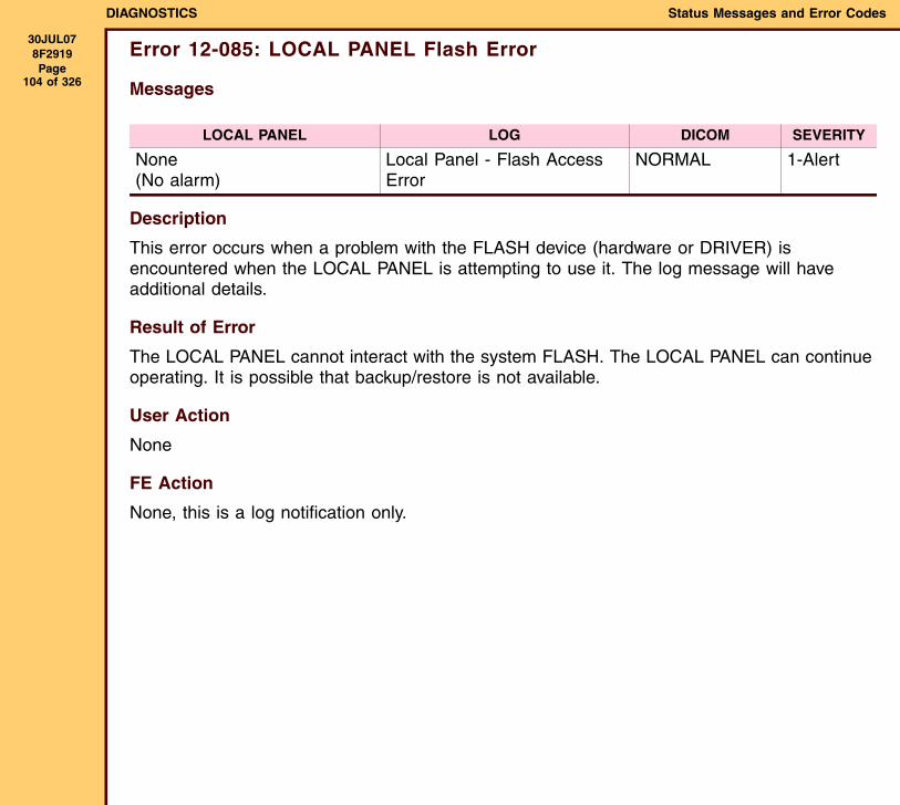
DIAGNOSTICS Status Messages and Error Codes
30JUL078F2919 Page
104 of 326
Error 12-085: LOCAL PANEL Flash Error
Messages
Description
This error occurs when a problem with the FLASH device (hardware or DRIVER) is encountered when the LOCAL PANEL is attempting to use it. The log message will have additional details.
Result of Error
The LOCAL PANEL cannot interact with the system FLASH. The LOCAL PANEL can continue operating. It is possible that backup/restore is not available.
User Action
None
FE Action
None, this is a log notification only.
LOCAL PANEL LOG DICOM SEVERITY
None (No alarm)
Local Panel - Flash Access Error
NORMAL 1-Alert
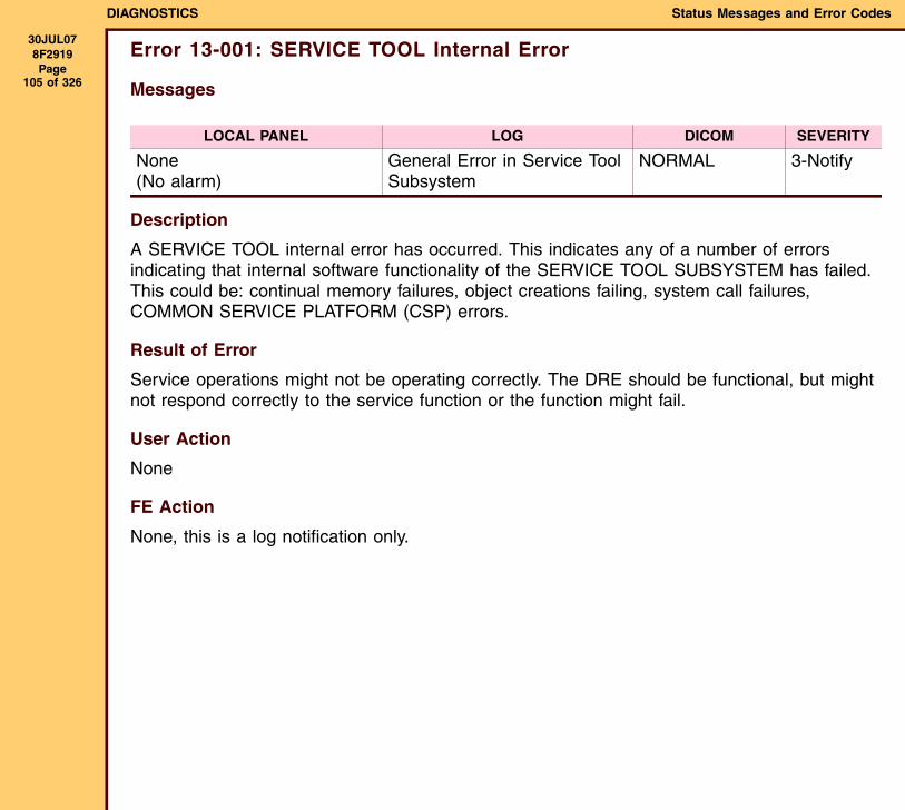
DIAGNOSTICS Status Messages and Error Codes
30JUL078F2919 Page
105 of 326
Error 13-001: SERVICE TOOL Internal Error
Messages
Description
A SERVICE TOOL internal error has occurred. This indicates any of a number of errors indicating that internal software functionality of the SERVICE TOOL SUBSYSTEM has failed. This could be: continual memory failures, object creations failing, system call failures, COMMON SERVICE PLATFORM (CSP) errors.
Result of Error
Service operations might not be operating correctly. The DRE should be functional, but might not respond correctly to the service function or the function might fail.
User Action
None
FE Action
None, this is a log notification only.
LOCAL PANEL LOG DICOM SEVERITY
None (No alarm)
General Error in Service Tool Subsystem
NORMAL 3-Notify
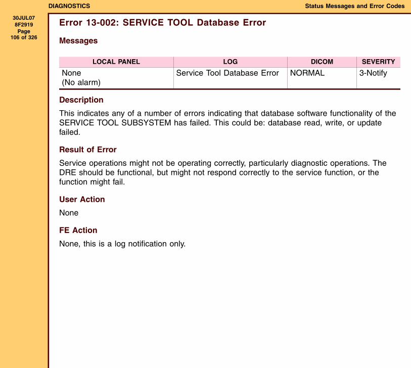
DIAGNOSTICS Status Messages and Error Codes
30JUL078F2919 Page
106 of 326
Error 13-002: SERVICE TOOL Database Error
Messages
Description
This indicates any of a number of errors indicating that database software functionality of the SERVICE TOOL SUBSYSTEM has failed. This could be: database read, write, or update failed.
Result of Error
Service operations might not be operating correctly, particularly diagnostic operations. The DRE should be functional, but might not respond correctly to the service function, or the function might fail.
User Action
None
FE Action
None, this is a log notification only.
LOCAL PANEL LOG DICOM SEVERITY
None (No alarm)
Service Tool Database Error NORMAL 3-Notify
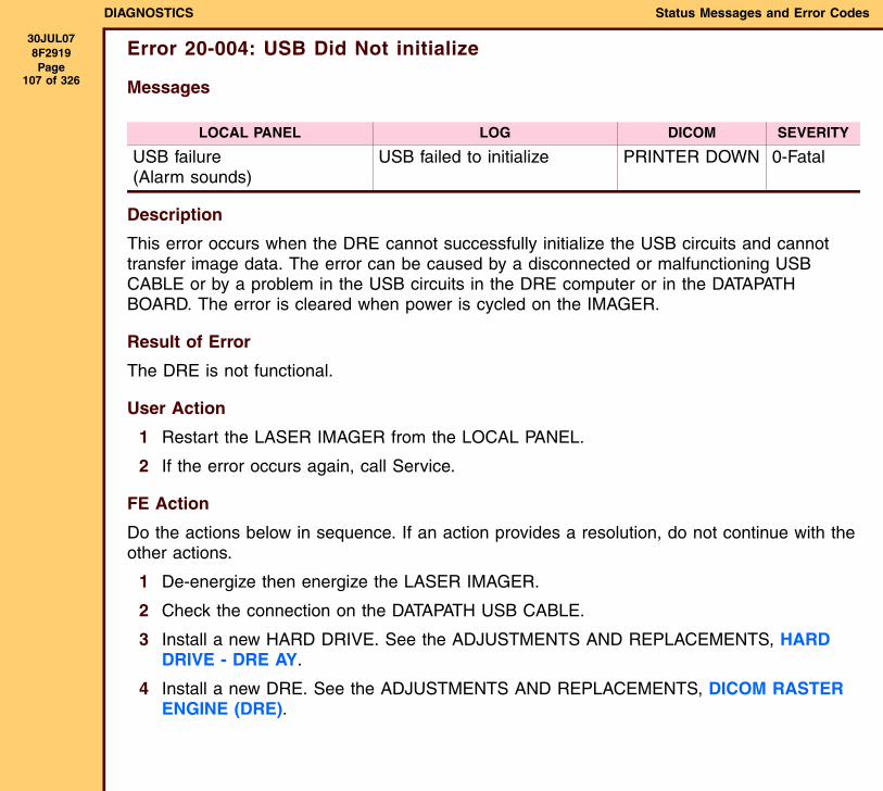
DIAGNOSTICS Status Messages and Error Codes
30JUL078F2919 Page
107 of 326
Error 20-004: USB Did Not initialize
Messages
Description
This error occurs when the DRE cannot successfully initialize the USB circuits and cannot transfer image data. The error can be caused by a disconnected or malfunctioning USB CABLE or by a problem in the USB circuits in the DRE computer or in the DATAPATH BOARD. The error is cleared when power is cycled on the IMAGER.
Result of Error
The DRE is not functional.
User Action
1 Restart the LASER IMAGER from the LOCAL PANEL.
2 If the error occurs again, call Service.
FE Action
Do the actions below in sequence. If an action provides a resolution, do not continue with the other actions.
1 De-energize then energize the LASER IMAGER.
2 Check the connection on the DATAPATH USB CABLE.
3 Install a new HARD DRIVE. See the ADJUSTMENTS AND REPLACEMENTS, HARD DRIVE - DRE AY.
4 Install a new DRE. See the ADJUSTMENTS AND REPLACEMENTS, DICOM RASTER ENGINE (DRE).
LOCAL PANEL LOG DICOM SEVERITY
USB failure(Alarm sounds)
USB failed to initialize PRINTER DOWN 0-Fatal
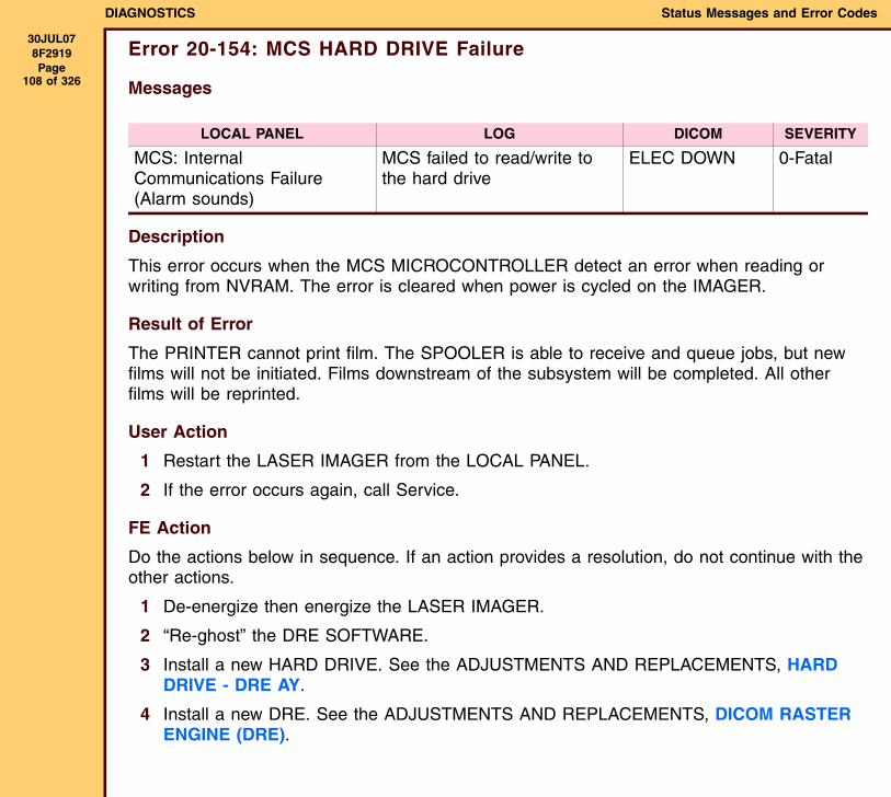
DIAGNOSTICS Status Messages and Error Codes
30JUL078F2919 Page
108 of 326
Error 20-154: MCS HARD DRIVE Failure
Messages
Description
This error occurs when the MCS MICROCONTROLLER detect an error when reading or writing from NVRAM. The error is cleared when power is cycled on the IMAGER.
Result of Error
The PRINTER cannot print film. The SPOOLER is able to receive and queue jobs, but new films will not be initiated. Films downstream of the subsystem will be completed. All other films will be reprinted.
User Action
1 Restart the LASER IMAGER from the LOCAL PANEL.
2 If the error occurs again, call Service.
FE Action
Do the actions below in sequence. If an action provides a resolution, do not continue with the other actions.
1 De-energize then energize the LASER IMAGER.
2 “Re-ghost” the DRE SOFTWARE.
3 Install a new HARD DRIVE. See the ADJUSTMENTS AND REPLACEMENTS, HARD DRIVE - DRE AY.
4 Install a new DRE. See the ADJUSTMENTS AND REPLACEMENTS, DICOM RASTER ENGINE (DRE).
LOCAL PANEL LOG DICOM SEVERITY
MCS: Internal Communications Failure(Alarm sounds)
MCS failed to read/write to the hard drive
ELEC DOWN 0-Fatal
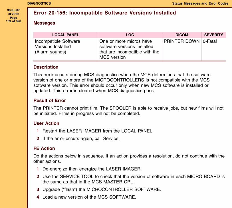
DIAGNOSTICS Status Messages and Error Codes
30JUL078F2919 Page
109 of 326
Error 20-156: Incompatible Software Versions Installed
Messages
Description
This error occurs during MCS diagnostics when the MCS determines that the software version of one or more of the MICROCONTROLLERS is not compatible with the MCS software version. This error should occur only when new MCS software is installed or updated. This error is cleared when MCS diagnostics pass.
Result of Error
The PRINTER cannot print film. The SPOOLER is able to receive jobs, but new films will not be initiated. Films in progress will not be completed.
User Action
1 Restart the LASER IMAGER from the LOCAL PANEL.
2 If the error occurs again, call Service.
FE Action
Do the actions below in sequence. If an action provides a resolution, do not continue with the other actions.
1 De-energize then energize the LASER IMAGER.
2 Use the SERVICE TOOL to check that the version of software in each MICRO BOARD is the same as that in the MCS MASTER CPU.
3 Upgrade (“flash”) the MICROCONTROLLER SOFTWARE.
4 Load a new version of the MCS SOFTWARE.
LOCAL PANEL LOG DICOM SEVERITY
Incompatible Software Versions Installed(Alarm sounds)
One or more micros have software versions installed that are incompatible with the MCS version
PRINTER DOWN 0-Fatal
DIAGNOSTICS Status Messages and Error Codes
30JUL078F2919 Page
110 of 326
5 Install a new MICRO BOARD.
6 Install a new HARD DRIVE. See the ADJUSTMENTS AND REPLACEMENTS, HARD DRIVE - DRE AY.
7 Install a new DRE. See the ADJUSTMENTS AND REPLACEMENTS, DICOM RASTER ENGINE (DRE).
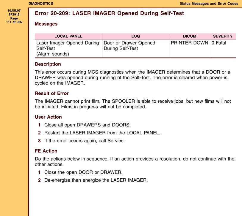
DIAGNOSTICS Status Messages and Error Codes
30JUL078F2919 Page
111 of 326
Error 20-209: LASER IMAGER Opened During Self-Test
Messages
Description
This error occurs during MCS diagnostics when the IMAGER determines that a DOOR or a DRAWER was opened during running of the Self-Test. The error is cleared when power is cycled on the IMAGER.
Result of Error
The IMAGER cannot print film. The SPOOLER is able to receive jobs, but new films will not be initiated. Films in progress will not be completed.
User Action
1 Close all open DRAWERS and DOORS.
2 Restart the LASER IMAGER from the LOCAL PANEL.
3 If the error occurs again, call Service.
FE Action
Do the actions below in sequence. If an action provides a resolution, do not continue with the other actions.
1 Close the open DOOR or DRAWER.
2 De-energize then energize the LASER IMAGER.
LOCAL PANEL LOG DICOM SEVERITY
Laser Imager Opened During Self-Test(Alarm sounds)
Door or Drawer Opened During Self-Test
PRINTER DOWN 0-Fatal
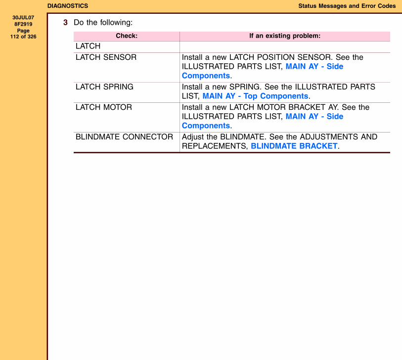
DIAGNOSTICS Status Messages and Error Codes
30JUL078F2919 Page
112 of 326
3 Do the following:
Check: If an existing problem:
LATCHLATCH SENSOR Install a new LATCH POSITION SENSOR. See the
ILLUSTRATED PARTS LIST, MAIN AY - Side Components.
LATCH SPRING Install a new SPRING. See the ILLUSTRATED PARTS LIST, MAIN AY - Top Components.
LATCH MOTOR Install a new LATCH MOTOR BRACKET AY. See the ILLUSTRATED PARTS LIST, MAIN AY - Side Components.
BLINDMATE CONNECTOR Adjust the BLINDMATE. See the ADJUSTMENTS AND REPLACEMENTS, BLINDMATE BRACKET.
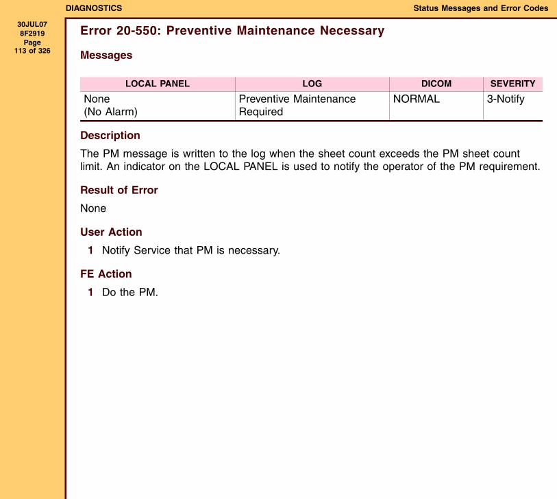
DIAGNOSTICS Status Messages and Error Codes
30JUL078F2919 Page
113 of 326
Error 20-550: Preventive Maintenance Necessary
Messages
Description
The PM message is written to the log when the sheet count exceeds the PM sheet count limit. An indicator on the LOCAL PANEL is used to notify the operator of the PM requirement.
Result of Error
None
User Action
1 Notify Service that PM is necessary.
FE Action
1 Do the PM.
LOCAL PANEL LOG DICOM SEVERITY
None(No Alarm)
Preventive Maintenance Required
NORMAL 3-Notify
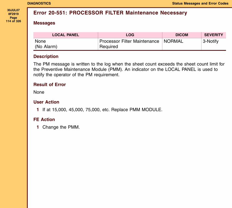
DIAGNOSTICS Status Messages and Error Codes
30JUL078F2919 Page
114 of 326
Error 20-551: PROCESSOR FILTER Maintenance Necessary
Messages
Description
The PM message is written to the log when the sheet count exceeds the sheet count limit for the Preventive Maintenance Module (PMM). An indicator on the LOCAL PANEL is used to notify the operator of the PM requirement.
Result of Error
None
User Action
1 If at 15,000, 45,000, 75,000, etc. Replace PMM MODULE.
FE Action
1 Change the PMM.
LOCAL PANEL LOG DICOM SEVERITY
None(No Alarm)
Processor Filter Maintenance Required
NORMAL 3-Notify
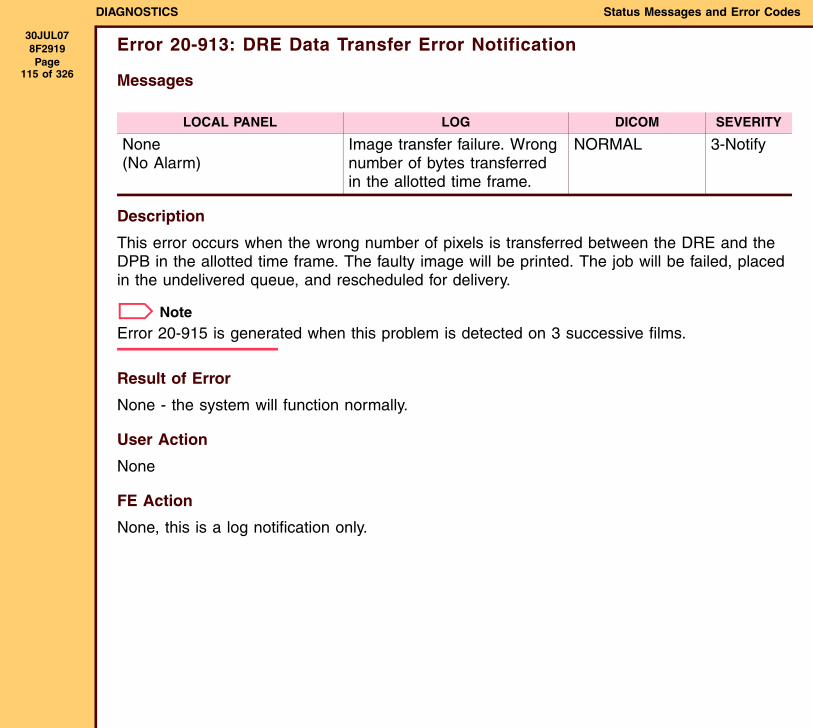
DIAGNOSTICS Status Messages and Error Codes
30JUL078F2919 Page
115 of 326
Error 20-913: DRE Data Transfer Error Notification
Messages
Description
This error occurs when the wrong number of pixels is transferred between the DRE and the DPB in the allotted time frame. The faulty image will be printed. The job will be failed, placed in the undelivered queue, and rescheduled for delivery.
NoteError 20-915 is generated when this problem is detected on 3 successive films.
Result of Error
None - the system will function normally.
User Action
None
FE Action
None, this is a log notification only.
LOCAL PANEL LOG DICOM SEVERITY
None(No Alarm)
Image transfer failure. Wrong number of bytes transferred in the allotted time frame.
NORMAL 3-Notify
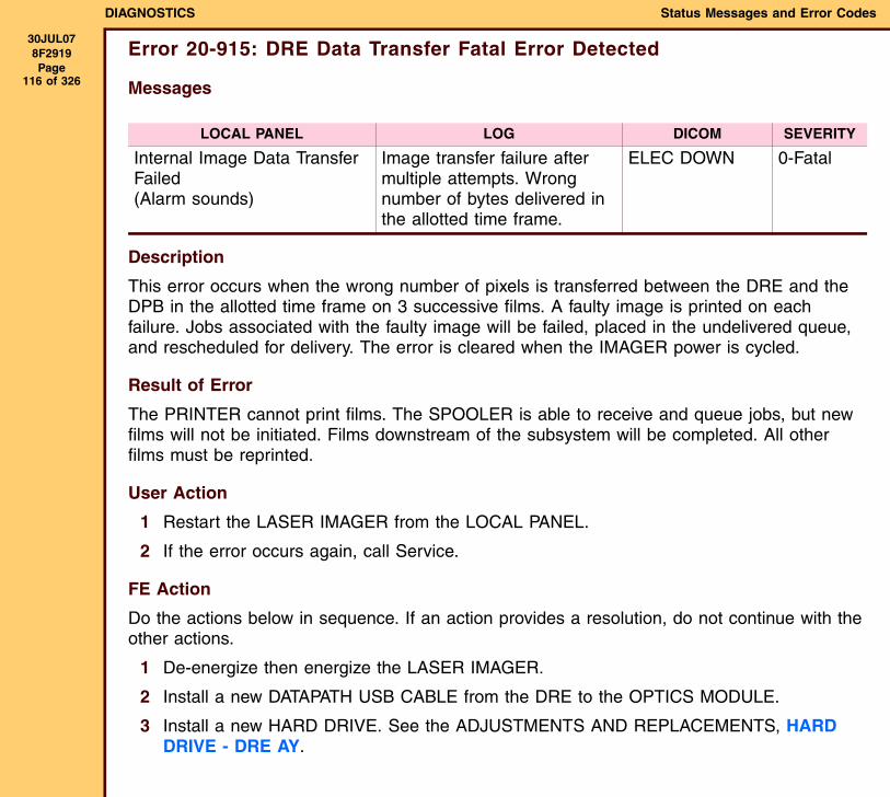
DIAGNOSTICS Status Messages and Error Codes
30JUL078F2919 Page
116 of 326
Error 20-915: DRE Data Transfer Fatal Error Detected
Messages
Description
This error occurs when the wrong number of pixels is transferred between the DRE and the DPB in the allotted time frame on 3 successive films. A faulty image is printed on each failure. Jobs associated with the faulty image will be failed, placed in the undelivered queue, and rescheduled for delivery. The error is cleared when the IMAGER power is cycled.
Result of Error
The PRINTER cannot print films. The SPOOLER is able to receive and queue jobs, but new films will not be initiated. Films downstream of the subsystem will be completed. All other films must be reprinted.
User Action
1 Restart the LASER IMAGER from the LOCAL PANEL.
2 If the error occurs again, call Service.
FE Action
Do the actions below in sequence. If an action provides a resolution, do not continue with the other actions.
1 De-energize then energize the LASER IMAGER.
2 Install a new DATAPATH USB CABLE from the DRE to the OPTICS MODULE.
3 Install a new HARD DRIVE. See the ADJUSTMENTS AND REPLACEMENTS, HARD DRIVE - DRE AY.
LOCAL PANEL LOG DICOM SEVERITY
Internal Image Data Transfer Failed(Alarm sounds)
Image transfer failure after multiple attempts. Wrong number of bytes delivered in the allotted time frame.
ELEC DOWN 0-Fatal

DIAGNOSTICS Status Messages and Error Codes
30JUL078F2919 Page
117 of 326
4 Install a new DRE. See the ADJUSTMENTS AND REPLACEMENTS, DICOM RASTER ENGINE (DRE).
5 Install a new OPTICS AY. See the ADJUSTMENTS AND REPLACEMENTS, OPTICS AY and EXPOSURE TRANSPORT AY.
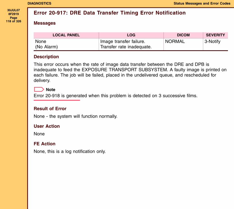
DIAGNOSTICS Status Messages and Error Codes
30JUL078F2919 Page
118 of 326
Error 20-917: DRE Data Transfer Timing Error Notification
Messages
Description
This error occurs when the rate of image data transfer between the DRE and DPB is inadequate to feed the EXPOSURE TRANSPORT SUBSYSTEM. A faulty image is printed on each failure. The job will be failed, placed in the undelivered queue, and rescheduled for delivery.
NoteError 20-918 is generated when this problem is detected on 3 successive films.
Result of Error
None - the system will function normally.
User Action
None
FE Action
None, this is a log notification only.
LOCAL PANEL LOG DICOM SEVERITY
None(No Alarm)
Image transfer failure. Transfer rate inadequate.
NORMAL 3-Notify
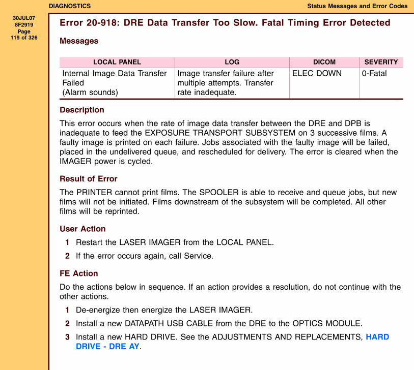
DIAGNOSTICS Status Messages and Error Codes
30JUL078F2919 Page
119 of 326
Error 20-918: DRE Data Transfer Too Slow. Fatal Timing Error Detected
Messages
Description
This error occurs when the rate of image data transfer between the DRE and DPB is inadequate to feed the EXPOSURE TRANSPORT SUBSYSTEM on 3 successive films. A faulty image is printed on each failure. Jobs associated with the faulty image will be failed, placed in the undelivered queue, and rescheduled for delivery. The error is cleared when the IMAGER power is cycled.
Result of Error
The PRINTER cannot print films. The SPOOLER is able to receive and queue jobs, but new films will not be initiated. Films downstream of the subsystem will be completed. All other films will be reprinted.
User Action
1 Restart the LASER IMAGER from the LOCAL PANEL.
2 If the error occurs again, call Service.
FE Action
Do the actions below in sequence. If an action provides a resolution, do not continue with the other actions.
1 De-energize then energize the LASER IMAGER.
2 Install a new DATAPATH USB CABLE from the DRE to the OPTICS MODULE.
3 Install a new HARD DRIVE. See the ADJUSTMENTS AND REPLACEMENTS, HARD DRIVE - DRE AY.
LOCAL PANEL LOG DICOM SEVERITY
Internal Image Data Transfer Failed(Alarm sounds)
Image transfer failure after multiple attempts. Transfer rate inadequate.
ELEC DOWN 0-Fatal
DIAGNOSTICS Status Messages and Error Codes
30JUL078F2919 Page
120 of 326
4 Install a new DRE. See the ADJUSTMENTS AND REPLACEMENTS, DICOM RASTER ENGINE (DRE).
5 Install a new OPTICS AY. See the ADJUSTMENTS AND REPLACEMENTS, OPTICS AY and EXPOSURE TRANSPORT AY.
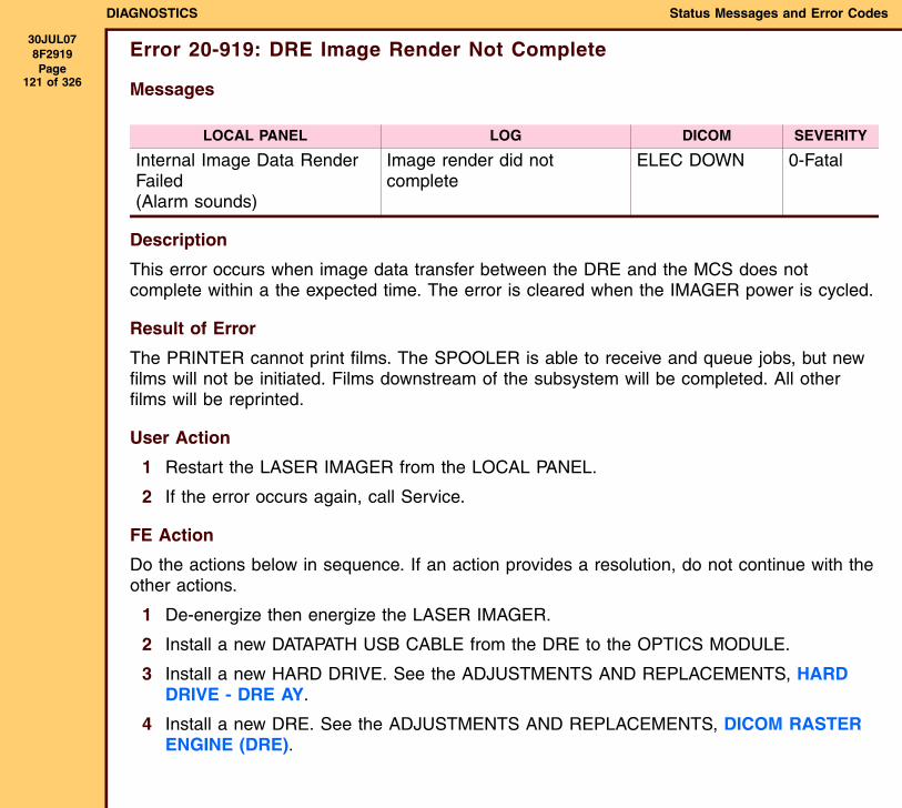
DIAGNOSTICS Status Messages and Error Codes
30JUL078F2919 Page
121 of 326
Error 20-919: DRE Image Render Not Complete
Messages
Description
This error occurs when image data transfer between the DRE and the MCS does not complete within a the expected time. The error is cleared when the IMAGER power is cycled.
Result of Error
The PRINTER cannot print films. The SPOOLER is able to receive and queue jobs, but new films will not be initiated. Films downstream of the subsystem will be completed. All other films will be reprinted.
User Action
1 Restart the LASER IMAGER from the LOCAL PANEL.
2 If the error occurs again, call Service.
FE Action
Do the actions below in sequence. If an action provides a resolution, do not continue with the other actions.
1 De-energize then energize the LASER IMAGER.
2 Install a new DATAPATH USB CABLE from the DRE to the OPTICS MODULE.
3 Install a new HARD DRIVE. See the ADJUSTMENTS AND REPLACEMENTS, HARD DRIVE - DRE AY.
4 Install a new DRE. See the ADJUSTMENTS AND REPLACEMENTS, DICOM RASTER ENGINE (DRE).
LOCAL PANEL LOG DICOM SEVERITY
Internal Image Data Render Failed(Alarm sounds)
Image render did not complete
ELEC DOWN 0-Fatal
DIAGNOSTICS Status Messages and Error Codes
30JUL078F2919 Page
122 of 326
5 Install a new OPTICS AY. See the ADJUSTMENTS AND REPLACEMENTS, OPTICS AY and EXPOSURE TRANSPORT AY.
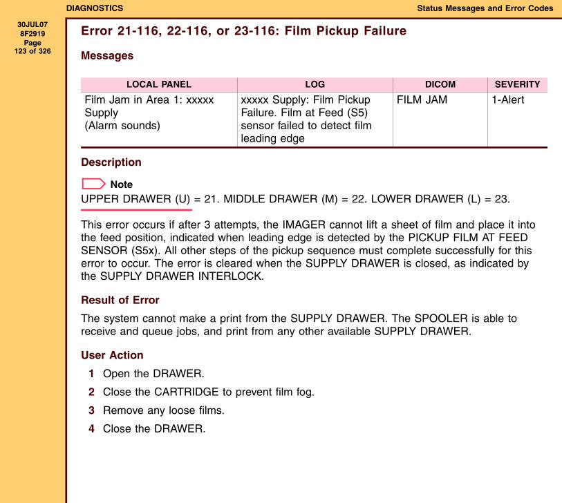
DIAGNOSTICS Status Messages and Error Codes
30JUL078F2919 Page
123 of 326
Error 21-116, 22-116, or 23-116: Film Pickup Failure
Messages
Description
NoteUPPER DRAWER (U) = 21. MIDDLE DRAWER (M) = 22. LOWER DRAWER (L) = 23.
This error occurs if after 3 attempts, the IMAGER cannot lift a sheet of film and place it into the feed position, indicated when leading edge is detected by the PICKUP FILM AT FEED SENSOR (S5x). All other steps of the pickup sequence must complete successfully for this error to occur. The error is cleared when the SUPPLY DRAWER is closed, as indicated by the SUPPLY DRAWER INTERLOCK.
Result of Error
The system cannot make a print from the SUPPLY DRAWER. The SPOOLER is able to receive and queue jobs, and print from any other available SUPPLY DRAWER.
User Action
1 Open the DRAWER.
2 Close the CARTRIDGE to prevent film fog.
3 Remove any loose films.
4 Close the DRAWER.
LOCAL PANEL LOG DICOM SEVERITY
Film Jam in Area 1: xxxxx Supply(Alarm sounds)
xxxxx Supply: Film Pickup Failure. Film at Feed (S5) sensor failed to detect film leading edge
FILM JAM 1-Alert
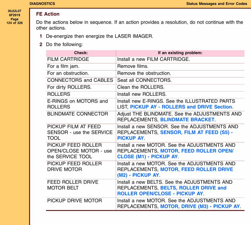
DIAGNOSTICS Status Messages and Error Codes
30JUL078F2919 Page
124 of 326
FE Action
Do the actions below in sequence. If an action provides a resolution, do not continue with the other actions.
1 De-energize then energize the LASER IMAGER.
2 Do the following:
Check: If an existing problem:
FILM CARTRIDGE Install a new FILM CARTRIDGE.For a film jam. Remove films.For an obstruction. Remove the obstruction.CONNECTORS and CABLES Seat all CONNECTORS.For dirty ROLLERS. Clean the ROLLERS.ROLLERS Install new ROLLERS.E-RINGS on MOTORS and ROLLERS
Install new E-RINGS. See the ILLUSTRATED PARTS LIST, PICKUP AY - ROLLERS and DRIVE Section.
BLINDMATE CONNECTOR Adjust THE BLINDMATE. See the ADJUSTMENTS AND REPLACEMENTS, BLINDMATE BRACKET.
PICKUP FILM AT FEED SENSOR - use the SERVICE TOOL
Install a new SENSOR. See the ADJUSTMENTS AND REPLACEMENTS, SENSOR, FILM AT FEED (S5) - PICKUP AY.
PICKUP FEED ROLLER OPEN/CLOSE MOTOR - use the SERVICE TOOL
Install a new MOTOR. See the ADJUSTMENTS AND REPLACEMENTS, MOTOR, FEED ROLLER OPEN/CLOSE (M1) - PICKUP AY.
PICKUP FEED ROLLER DRIVE MOTOR
Install a new MOTOR. See the ADJUSTMENTS AND REPLACEMENTS, MOTOR, FEED ROLLER DRIVE (M2) - PICKUP AY.
FEED ROLLER DRIVE MOTOR BELT
Install a new BELTS. See the ADJUSTMENTS AND REPLACEMENTS, BELTS, ROLLER DRIVE and ROLLER OPEN/CLOSE - PICKUP AY.
PICKUP DRIVE MOTOR Install a new MOTOR. See the ADJUSTMENTS AND REPLACEMENTS, MOTOR, DRIVE (M3) - PICKUP AY.
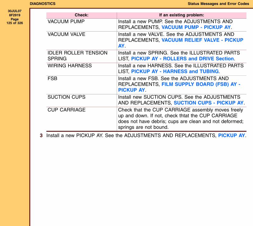
DIAGNOSTICS Status Messages and Error Codes
30JUL078F2919 Page
125 of 326
3 Install a new PICKUP AY. See the ADJUSTMENTS AND REPLACEMENTS, PICKUP AY.
VACUUM PUMP Install a new PUMP. See the ADJUSTMENTS AND REPLACEMENTS, VACUUM PUMP - PICKUP AY.
VACUUM VALVE Install a new VALVE. See the ADJUSTMENTS AND REPLACEMENTS, VACUUM RELIEF VALVE - PICKUP AY.
IDLER ROLLER TENSION SPRING
Install a new SPRING. See the ILLUSTRATED PARTS LIST, PICKUP AY - ROLLERS and DRIVE Section.
WIRING HARNESS Install a new HARNESS. See the ILLUSTRATED PARTS LIST, PICKUP AY - HARNESS and TUBING.
FSB Install a new FSB. See the ADJUSTMENTS AND REPLACEMENTS, FILM SUPPLY BOARD (FSB) AY - PICKUP AY.
SUCTION CUPS Install new SUCTION CUPS. See the ADJUSTMENTS AND REPLACEMENTS, SUCTION CUPS - PICKUP AY.
CUP CARRIAGE Check that the CUP CARRIAGE assembly moves freely up and down. If not, check thtat the CUP CARRIAGE does not have debris; cups are clean and not deformed; springs are not bound.
Check: If an existing problem:
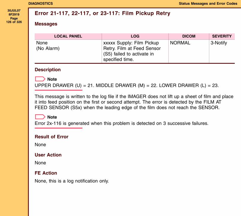
DIAGNOSTICS Status Messages and Error Codes
30JUL078F2919 Page
126 of 326
Error 21-117, 22-117, or 23-117: Film Pickup Retry
Messages
Description
NoteUPPER DRAWER (U) = 21. MIDDLE DRAWER (M) = 22. LOWER DRAWER (L) = 23.
This message is written to the log file if the IMAGER does not lift up a sheet of film and place it into feed position on the first or second attempt. The error is detected by the FILM AT FEED SENSOR (S5x) when the leading edge of the film does not reach the SENSOR.
NoteError 2x-116 is generated when this problem is detected on 3 successive failures.
Result of Error
None
User Action
None
FE Action
None, this is a log notification only.
LOCAL PANEL LOG DICOM SEVERITY
None(No Alarm)
xxxxx Supply: Film Pickup Retry. Film at Feed Sensor (S5) failed to activate in specified time.
NORMAL 3-Notify
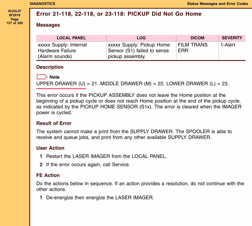
DIAGNOSTICS Status Messages and Error Codes
30JUL078F2919 Page
127 of 326
Error 21-118, 22-118, or 23-118: PICKUP Did Not Go Home
Messages
Description
NoteUPPER DRAWER (U) = 21. MIDDLE DRAWER (M) = 22. LOWER DRAWER (L) = 23.
This error occurs if the PICKUP ASSEMBLY does not leave the Home position at the beginning of a pickup cycle or does not reach Home position at the end of the pickup cycle, as indicated by the PICKUP HOME SENSOR (S1x). The error is cleared when the IMAGER power is cycled.
Result of Error
The system cannot make a print from the SUPPLY DRAWER. The SPOOLER is able to receive and queue jobs, and print from any other available SUPPLY DRAWER.
User Action
1 Restart the LASER IMAGER from the LOCAL PANEL.
2 If the error occurs again, call Service.
FE Action
Do the actions below in sequence. If an action provides a resolution, do not continue with the other actions.
1 De-energize then energize the LASER IMAGER.
LOCAL PANEL LOG DICOM SEVERITY
xxxxx Supply: Internal Hardware Failure(Alarm sounds)
xxxxx Supply: Pickup Home Sensor (S1) failed to sense pickup assembly.
FILM TRANS ERR
1-Alert
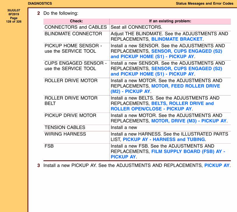
DIAGNOSTICS Status Messages and Error Codes
30JUL078F2919 Page
128 of 326
2 Do the following:
3 Install a new PICKUP AY. See the ADJUSTMENTS AND REPLACEMENTS, PICKUP AY.
Check: If an existing problem:
CONNECTORS and CABLES Seat all CONNECTORS.BLINDMATE CONNECTOR Adjust THE BLINDMATE. See the ADJUSTMENTS AND
REPLACEMENTS, BLINDMATE BRACKET.PICKUP HOME SENSOR - use the SERVICE TOOL
Install a new SENSOR. See the ADJUSTMENTS AND REPLACEMENTS, SENSOR, CUPS ENGAGED (S2) and PICKUP HOME (S1) - PICKUP AY.
CUPS ENGAGED SENSOR - use the SERVICE TOOL
Install a new SENSOR. See the ADJUSTMENTS AND REPLACEMENTS, SENSOR, CUPS ENGAGED (S2) and PICKUP HOME (S1) - PICKUP AY.
ROLLER DRIVE MOTOR Install a new MOTOR. See the ADJUSTMENTS AND REPLACEMENTS, MOTOR, FEED ROLLER DRIVE (M2) - PICKUP AY.
ROLLER DRIVE MOTOR BELT
Install a new BELTS. See the ADJUSTMENTS AND REPLACEMENTS, BELTS, ROLLER DRIVE and ROLLER OPEN/CLOSE - PICKUP AY.
PICKUP DRIVE MOTOR Install a new MOTOR. See the ADJUSTMENTS AND REPLACEMENTS, MOTOR, DRIVE (M3) - PICKUP AY.
TENSION CABLES Install a new WIRING HARNESS Install a new HARNESS. See the ILLUSTRATED PARTS
LIST, PICKUP AY - HARNESS and TUBING.FSB Install a new FSB. See the ADJUSTMENTS AND
REPLACEMENTS, FILM SUPPLY BOARD (FSB) AY - PICKUP AY.
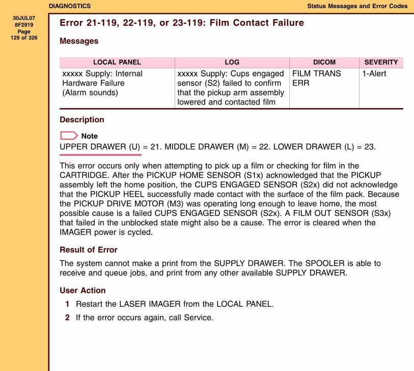
DIAGNOSTICS Status Messages and Error Codes
30JUL078F2919 Page
129 of 326
Error 21-119, 22-119, or 23-119: Film Contact Failure
Messages
Description
NoteUPPER DRAWER (U) = 21. MIDDLE DRAWER (M) = 22. LOWER DRAWER (L) = 23.
This error occurs only when attempting to pick up a film or checking for film in the CARTRIDGE. After the PICKUP HOME SENSOR (S1x) acknowledged that the PICKUP assembly left the home position, the CUPS ENGAGED SENSOR (S2x) did not acknowledge that the PICKUP HEEL successfully made contact with the surface of the film pack. Because the PICKUP DRIVE MOTOR (M3) was operating long enough to leave home, the most possible cause is a failed CUPS ENGAGED SENSOR (S2x). A FILM OUT SENSOR (S3x) that failed in the unblocked state might also be a cause. The error is cleared when the IMAGER power is cycled.
Result of Error
The system cannot make a print from the SUPPLY DRAWER. The SPOOLER is able to receive and queue jobs, and print from any other available SUPPLY DRAWER.
User Action
1 Restart the LASER IMAGER from the LOCAL PANEL.
2 If the error occurs again, call Service.
LOCAL PANEL LOG DICOM SEVERITY
xxxxx Supply: Internal Hardware Failure(Alarm sounds)
xxxxx Supply: Cups engaged sensor (S2) failed to confirm that the pickup arm assembly lowered and contacted film
FILM TRANS ERR
1-Alert
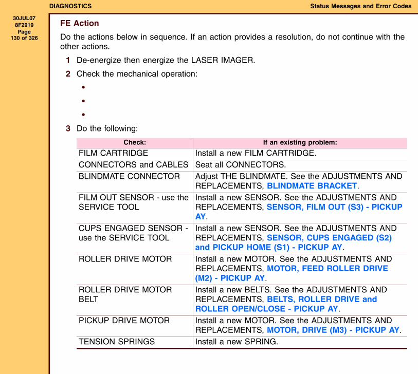
DIAGNOSTICS Status Messages and Error Codes
30JUL078F2919 Page
130 of 326
FE Action
Do the actions below in sequence. If an action provides a resolution, do not continue with the other actions.
1 De-energize then energize the LASER IMAGER.
2 Check the mechanical operation:
•
•
•
3 Do the following:
Check: If an existing problem:
FILM CARTRIDGE Install a new FILM CARTRIDGE.CONNECTORS and CABLES Seat all CONNECTORS.BLINDMATE CONNECTOR Adjust THE BLINDMATE. See the ADJUSTMENTS AND
REPLACEMENTS, BLINDMATE BRACKET.FILM OUT SENSOR - use the SERVICE TOOL
Install a new SENSOR. See the ADJUSTMENTS AND REPLACEMENTS, SENSOR, FILM OUT (S3) - PICKUP AY.
CUPS ENGAGED SENSOR - use the SERVICE TOOL
Install a new SENSOR. See the ADJUSTMENTS AND REPLACEMENTS, SENSOR, CUPS ENGAGED (S2) and PICKUP HOME (S1) - PICKUP AY.
ROLLER DRIVE MOTOR Install a new MOTOR. See the ADJUSTMENTS AND REPLACEMENTS, MOTOR, FEED ROLLER DRIVE (M2) - PICKUP AY.
ROLLER DRIVE MOTOR BELT
Install a new BELTS. See the ADJUSTMENTS AND REPLACEMENTS, BELTS, ROLLER DRIVE and ROLLER OPEN/CLOSE - PICKUP AY.
PICKUP DRIVE MOTOR Install a new MOTOR. See the ADJUSTMENTS AND REPLACEMENTS, MOTOR, DRIVE (M3) - PICKUP AY.
TENSION SPRINGS Install a new SPRING.
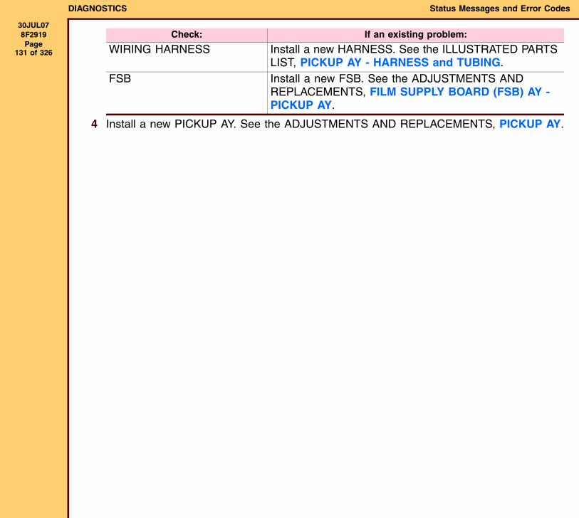
DIAGNOSTICS Status Messages and Error Codes
30JUL078F2919 Page
131 of 326
4 Install a new PICKUP AY. See the ADJUSTMENTS AND REPLACEMENTS, PICKUP AY.
WIRING HARNESS Install a new HARNESS. See the ILLUSTRATED PARTS LIST, PICKUP AY - HARNESS and TUBING.
FSB Install a new FSB. See the ADJUSTMENTS AND REPLACEMENTS, FILM SUPPLY BOARD (FSB) AY - PICKUP AY.
Check: If an existing problem:
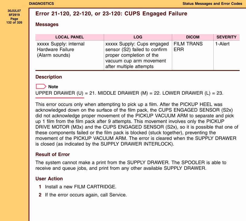
DIAGNOSTICS Status Messages and Error Codes
30JUL078F2919 Page
132 of 326
Error 21-120, 22-120, or 23-120: CUPS Engaged Failure
Messages
Description
NoteUPPER DRAWER (U) = 21. MIDDLE DRAWER (M) = 22. LOWER DRAWER (L) = 23.
This error occurs only when attempting to pick up a film. After the PICKUP HEEL was acknowledged down on the surface of the film pack, the CUPS ENGAGED SENSOR (S2x) did not acknowledge proper movement of the PICKUP VACUUM ARM to separate and pick up 1 film from the film pack after 9 attempts. This movement involves only the PICKUP DRIVE MOTOR (M3x) and the CUPS ENGAGED SENSOR (S2x), so it is possible that one of these components failed or the film pack is blocked (stuck together), preventing the movement of the PICKUP VACUUM ARM. The error is cleared when the SUPPLY DRAWER is closed (as indicated by the SUPPLY DRAWER INTERLOCK).
Result of Error
The system cannot make a print from the SUPPLY DRAWER. The SPOOLER is able to receive and queue jobs, and print from any other available SUPPLY DRAWER.
User Action
1 Install a new FILM CARTRIDGE.
2 If the error occurs again, call Service.
LOCAL PANEL LOG DICOM SEVERITY
xxxxx Supply: internal Hardware Failure(Alarm sounds)
xxxxx Supply: Cups engaged sensor (S2) failed to confirm proper completion of the vacuum cup arm movement after multiple attempts
FILM TRANS ERR
1-Alert
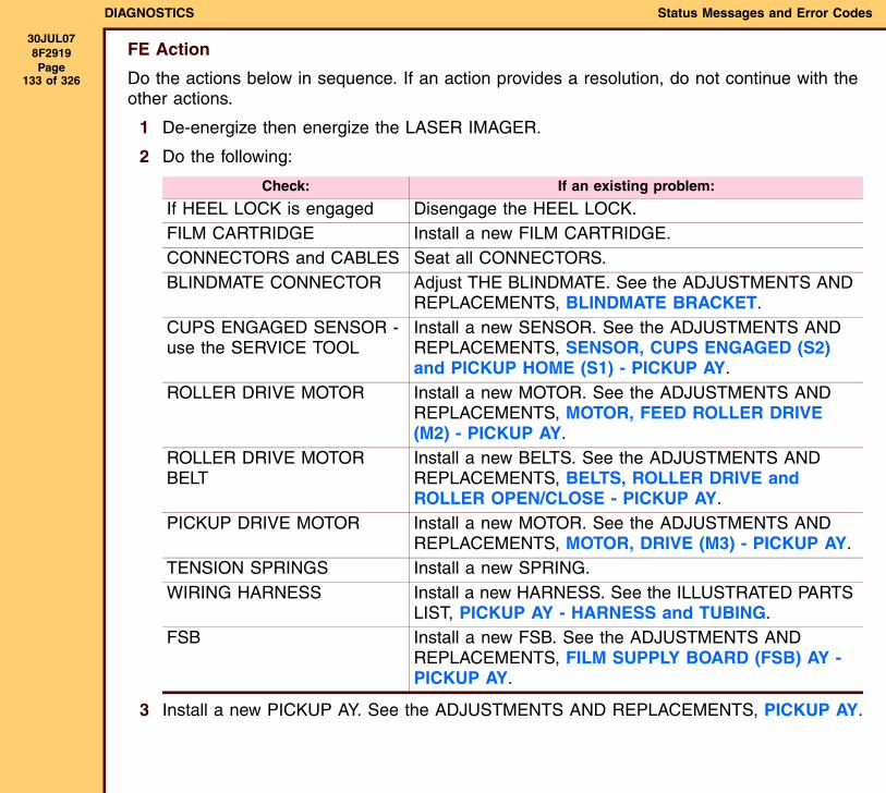
DIAGNOSTICS Status Messages and Error Codes
30JUL078F2919 Page
133 of 326
FE Action
Do the actions below in sequence. If an action provides a resolution, do not continue with the other actions.
1 De-energize then energize the LASER IMAGER.
2 Do the following:
3 Install a new PICKUP AY. See the ADJUSTMENTS AND REPLACEMENTS, PICKUP AY.
Check: If an existing problem:
If HEEL LOCK is engaged Disengage the HEEL LOCK.FILM CARTRIDGE Install a new FILM CARTRIDGE.CONNECTORS and CABLES Seat all CONNECTORS.BLINDMATE CONNECTOR Adjust THE BLINDMATE. See the ADJUSTMENTS AND
REPLACEMENTS, BLINDMATE BRACKET.CUPS ENGAGED SENSOR - use the SERVICE TOOL
Install a new SENSOR. See the ADJUSTMENTS AND REPLACEMENTS, SENSOR, CUPS ENGAGED (S2) and PICKUP HOME (S1) - PICKUP AY.
ROLLER DRIVE MOTOR Install a new MOTOR. See the ADJUSTMENTS AND REPLACEMENTS, MOTOR, FEED ROLLER DRIVE (M2) - PICKUP AY.
ROLLER DRIVE MOTOR BELT
Install a new BELTS. See the ADJUSTMENTS AND REPLACEMENTS, BELTS, ROLLER DRIVE and ROLLER OPEN/CLOSE - PICKUP AY.
PICKUP DRIVE MOTOR Install a new MOTOR. See the ADJUSTMENTS AND REPLACEMENTS, MOTOR, DRIVE (M3) - PICKUP AY.
TENSION SPRINGS Install a new SPRING.WIRING HARNESS Install a new HARNESS. See the ILLUSTRATED PARTS
LIST, PICKUP AY - HARNESS and TUBING.FSB Install a new FSB. See the ADJUSTMENTS AND
REPLACEMENTS, FILM SUPPLY BOARD (FSB) AY - PICKUP AY.
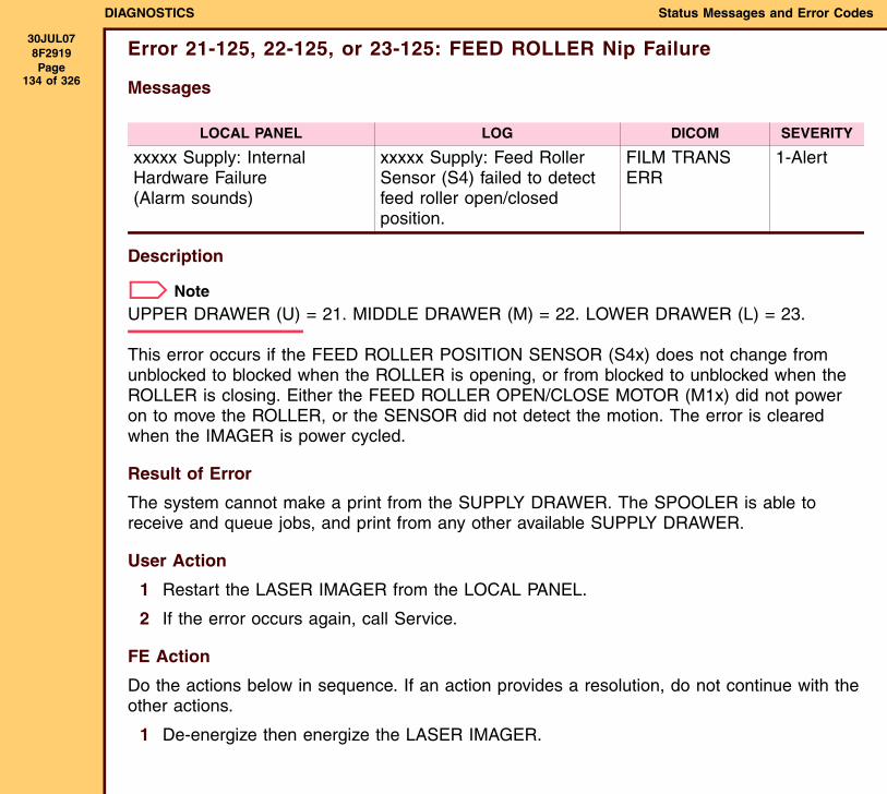
DIAGNOSTICS Status Messages and Error Codes
30JUL078F2919 Page
134 of 326
Error 21-125, 22-125, or 23-125: FEED ROLLER Nip Failure
Messages
Description
NoteUPPER DRAWER (U) = 21. MIDDLE DRAWER (M) = 22. LOWER DRAWER (L) = 23.
This error occurs if the FEED ROLLER POSITION SENSOR (S4x) does not change from unblocked to blocked when the ROLLER is opening, or from blocked to unblocked when the ROLLER is closing. Either the FEED ROLLER OPEN/CLOSE MOTOR (M1x) did not power on to move the ROLLER, or the SENSOR did not detect the motion. The error is cleared when the IMAGER is power cycled.
Result of Error
The system cannot make a print from the SUPPLY DRAWER. The SPOOLER is able to receive and queue jobs, and print from any other available SUPPLY DRAWER.
User Action
1 Restart the LASER IMAGER from the LOCAL PANEL.
2 If the error occurs again, call Service.
FE Action
Do the actions below in sequence. If an action provides a resolution, do not continue with the other actions.
1 De-energize then energize the LASER IMAGER.
LOCAL PANEL LOG DICOM SEVERITY
xxxxx Supply: Internal Hardware Failure(Alarm sounds)
xxxxx Supply: Feed Roller Sensor (S4) failed to detect feed roller open/closed position.
FILM TRANS ERR
1-Alert
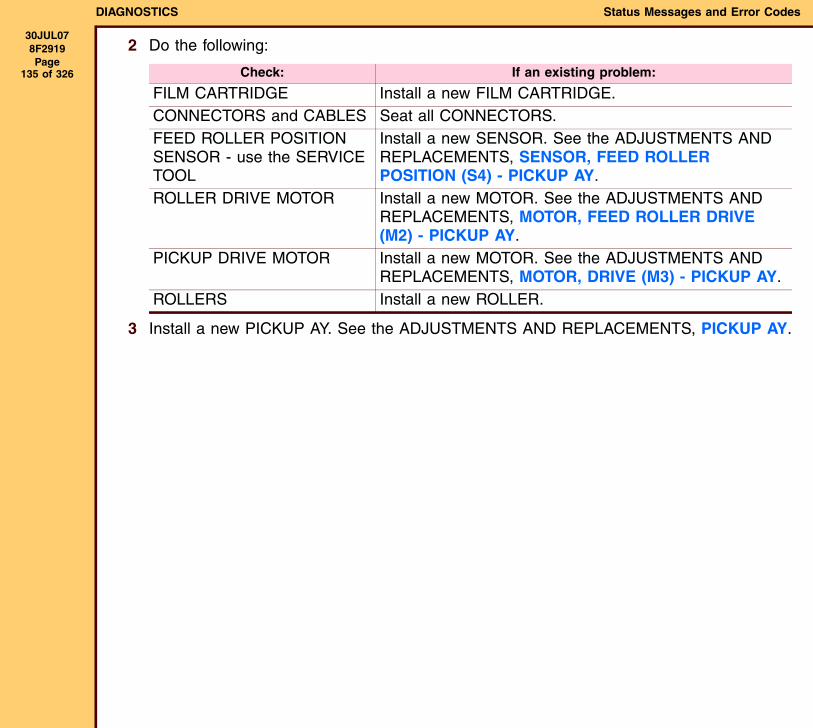
DIAGNOSTICS Status Messages and Error Codes
30JUL078F2919 Page
135 of 326
2 Do the following:
3 Install a new PICKUP AY. See the ADJUSTMENTS AND REPLACEMENTS, PICKUP AY.
Check: If an existing problem:
FILM CARTRIDGE Install a new FILM CARTRIDGE.CONNECTORS and CABLES Seat all CONNECTORS.FEED ROLLER POSITION SENSOR - use the SERVICE TOOL
Install a new SENSOR. See the ADJUSTMENTS AND REPLACEMENTS, SENSOR, FEED ROLLER POSITION (S4) - PICKUP AY.
ROLLER DRIVE MOTOR Install a new MOTOR. See the ADJUSTMENTS AND REPLACEMENTS, MOTOR, FEED ROLLER DRIVE (M2) - PICKUP AY.
PICKUP DRIVE MOTOR Install a new MOTOR. See the ADJUSTMENTS AND REPLACEMENTS, MOTOR, DRIVE (M3) - PICKUP AY.
ROLLERS Install a new ROLLER.
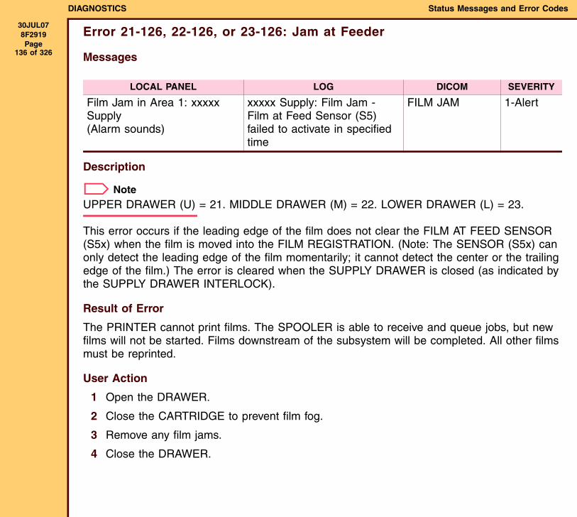
DIAGNOSTICS Status Messages and Error Codes
30JUL078F2919 Page
136 of 326
Error 21-126, 22-126, or 23-126: Jam at Feeder
Messages
Description
NoteUPPER DRAWER (U) = 21. MIDDLE DRAWER (M) = 22. LOWER DRAWER (L) = 23.
This error occurs if the leading edge of the film does not clear the FILM AT FEED SENSOR (S5x) when the film is moved into the FILM REGISTRATION. (Note: The SENSOR (S5x) can only detect the leading edge of the film momentarily; it cannot detect the center or the trailing edge of the film.) The error is cleared when the SUPPLY DRAWER is closed (as indicated by the SUPPLY DRAWER INTERLOCK).
Result of Error
The PRINTER cannot print films. The SPOOLER is able to receive and queue jobs, but new films will not be started. Films downstream of the subsystem will be completed. All other films must be reprinted.
User Action
1 Open the DRAWER.
2 Close the CARTRIDGE to prevent film fog.
3 Remove any film jams.
4 Close the DRAWER.
LOCAL PANEL LOG DICOM SEVERITY
Film Jam in Area 1: xxxxx Supply(Alarm sounds)
xxxxx Supply: Film Jam - Film at Feed Sensor (S5) failed to activate in specified time
FILM JAM 1-Alert
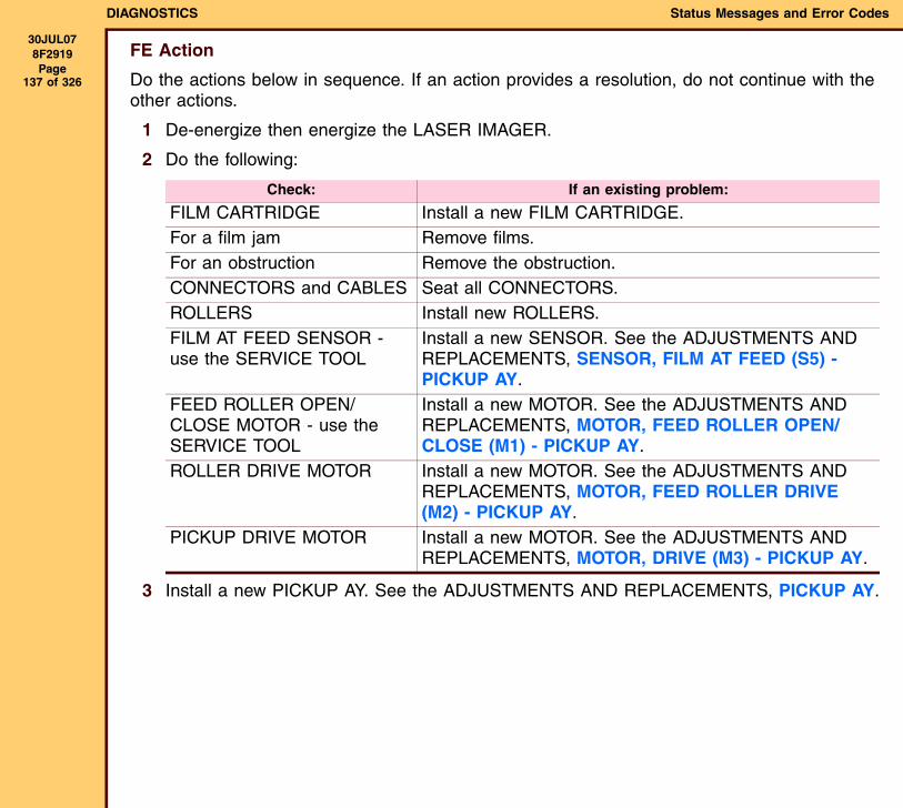
DIAGNOSTICS Status Messages and Error Codes
30JUL078F2919 Page
137 of 326
FE Action
Do the actions below in sequence. If an action provides a resolution, do not continue with the other actions.
1 De-energize then energize the LASER IMAGER.
2 Do the following:
3 Install a new PICKUP AY. See the ADJUSTMENTS AND REPLACEMENTS, PICKUP AY.
Check: If an existing problem:
FILM CARTRIDGE Install a new FILM CARTRIDGE.For a film jam Remove films.For an obstruction Remove the obstruction.CONNECTORS and CABLES Seat all CONNECTORS.ROLLERS Install new ROLLERS.FILM AT FEED SENSOR - use the SERVICE TOOL
Install a new SENSOR. See the ADJUSTMENTS AND REPLACEMENTS, SENSOR, FILM AT FEED (S5) - PICKUP AY.
FEED ROLLER OPEN/CLOSE MOTOR - use the SERVICE TOOL
Install a new MOTOR. See the ADJUSTMENTS AND REPLACEMENTS, MOTOR, FEED ROLLER OPEN/CLOSE (M1) - PICKUP AY.
ROLLER DRIVE MOTOR Install a new MOTOR. See the ADJUSTMENTS AND REPLACEMENTS, MOTOR, FEED ROLLER DRIVE (M2) - PICKUP AY.
PICKUP DRIVE MOTOR Install a new MOTOR. See the ADJUSTMENTS AND REPLACEMENTS, MOTOR, DRIVE (M3) - PICKUP AY.
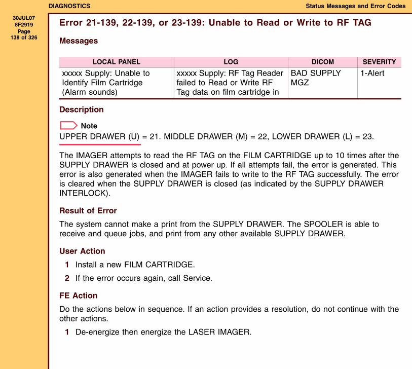
DIAGNOSTICS Status Messages and Error Codes
30JUL078F2919 Page
138 of 326
Error 21-139, 22-139, or 23-139: Unable to Read or Write to RF TAG
Messages
Description
NoteUPPER DRAWER (U) = 21. MIDDLE DRAWER (M) = 22, LOWER DRAWER (L) = 23.
The IMAGER attempts to read the RF TAG on the FILM CARTRIDGE up to 10 times after the SUPPLY DRAWER is closed and at power up. If all attempts fail, the error is generated. This error is also generated when the IMAGER fails to write to the RF TAG successfully. The error is cleared when the SUPPLY DRAWER is closed (as indicated by the SUPPLY DRAWER INTERLOCK).
Result of Error
The system cannot make a print from the SUPPLY DRAWER. The SPOOLER is able to receive and queue jobs, and print from any other available SUPPLY DRAWER.
User Action
1 Install a new FILM CARTRIDGE.
2 If the error occurs again, call Service.
FE Action
Do the actions below in sequence. If an action provides a resolution, do not continue with the other actions.
1 De-energize then energize the LASER IMAGER.
LOCAL PANEL LOG DICOM SEVERITY
xxxxx Supply: Unable to Identify Film Cartridge(Alarm sounds)
xxxxx Supply: RF Tag Reader failed to Read or Write RF Tag data on film cartridge in
BAD SUPPLY MGZ
1-Alert

DIAGNOSTICS Status Messages and Error Codes
30JUL078F2919 Page
139 of 326
2 Do the following:
Check: If an existing problem:
FILM CARTRIDGE Install a new FILM CARTRIDGE.CONNECTORS and CABLES Seat all CONNECTORS.BLINDMATE CONNECTOR Adjust THE BLINDMATE. See the ADJUSTMENTS AND
REPLACEMENTS, BLINDMATE BRACKET.RF TAG ANTENNA CABLE 1. Seat the CONNECTOR.
2. Install a new HARNESS. See the ADJUSTMENTS AND REPLACEMENTS, HARNESS - ROLLBACK AY.
RF ANTENNA BOARD Install a new BOARD. See the ADJUSTMENTS AND REPLACEMENTS, RF ANTENNA BOARD AY - ROLLBACK AY.
FSB Install a new FSB. See the ADJUSTMENTS AND REPLACEMENTS, FILM SUPPLY BOARD (FSB) AY - PICKUP AY.
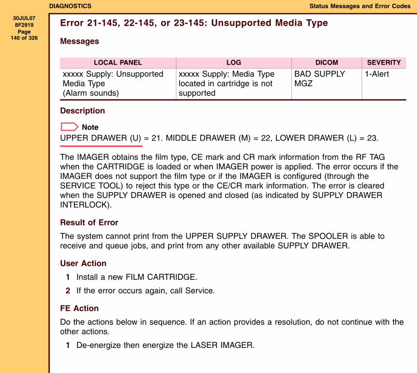
DIAGNOSTICS Status Messages and Error Codes
30JUL078F2919 Page
140 of 326
Error 21-145, 22-145, or 23-145: Unsupported Media Type
Messages
Description
NoteUPPER DRAWER (U) = 21. MIDDLE DRAWER (M) = 22, LOWER DRAWER (L) = 23.
The IMAGER obtains the film type, CE mark and CR mark information from the RF TAG when the CARTRIDGE is loaded or when IMAGER power is applied. The error occurs if the IMAGER does not support the film type or if the IMAGER is configured (through the SERVICE TOOL) to reject this type or the CE/CR mark information. The error is cleared when the SUPPLY DRAWER is opened and closed (as indicated by SUPPLY DRAWER INTERLOCK).
Result of Error
The system cannot print from the UPPER SUPPLY DRAWER. The SPOOLER is able to receive and queue jobs, and print from any other available SUPPLY DRAWER.
User Action
1 Install a new FILM CARTRIDGE.
2 If the error occurs again, call Service.
FE Action
Do the actions below in sequence. If an action provides a resolution, do not continue with the other actions.
1 De-energize then energize the LASER IMAGER.
LOCAL PANEL LOG DICOM SEVERITY
xxxxx Supply: Unsupported Media Type(Alarm sounds)
xxxxx Supply: Media Type located in cartridge is not supported
BAD SUPPLY MGZ
1-Alert

DIAGNOSTICS Status Messages and Error Codes
30JUL078F2919 Page
141 of 326
2 Do the following:
Check: If an existing problem:
FILM CARTRIDGE Install a new FILM CARTRIDGE.CONNECTORS and CABLES Seat all CONNECTORS.BLINDMATE CONNECTOR Adjust THE BLINDMATE. See the ADJUSTMENTS AND
REPLACEMENTS, BLINDMATE BRACKET.RF TAG ANTENNA CABLE 1. Seat the CONNECTOR.
2. Install a new HARNESS. See the ADJUSTMENTS AND REPLACEMENTS, HARNESS - ROLLBACK AY.
RF ANTENNA BOARD Install a new BOARD. See the ADJUSTMENTS AND REPLACEMENTS, RF ANTENNA BOARD AY - ROLLBACK AY.
FSB Install a new FSB. See the ADJUSTMENTS AND REPLACEMENTS, FILM SUPPLY BOARD (FSB) AY - PICKUP AY.
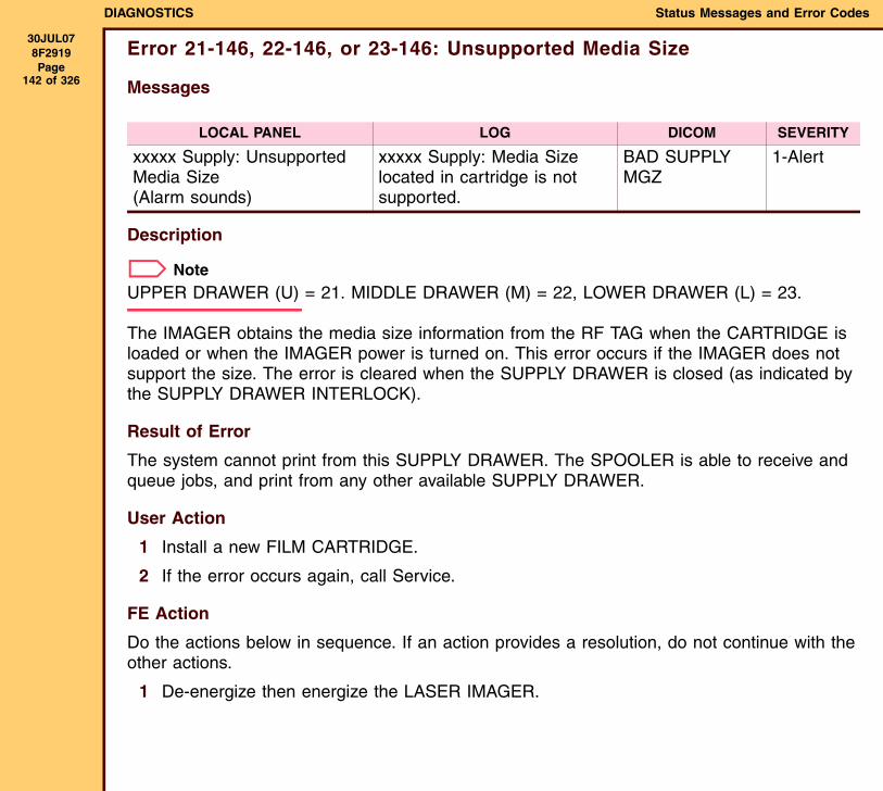
DIAGNOSTICS Status Messages and Error Codes
30JUL078F2919 Page
142 of 326
Error 21-146, 22-146, or 23-146: Unsupported Media Size
Messages
Description
NoteUPPER DRAWER (U) = 21. MIDDLE DRAWER (M) = 22, LOWER DRAWER (L) = 23.
The IMAGER obtains the media size information from the RF TAG when the CARTRIDGE is loaded or when the IMAGER power is turned on. This error occurs if the IMAGER does not support the size. The error is cleared when the SUPPLY DRAWER is closed (as indicated by the SUPPLY DRAWER INTERLOCK).
Result of Error
The system cannot print from this SUPPLY DRAWER. The SPOOLER is able to receive and queue jobs, and print from any other available SUPPLY DRAWER.
User Action
1 Install a new FILM CARTRIDGE.
2 If the error occurs again, call Service.
FE Action
Do the actions below in sequence. If an action provides a resolution, do not continue with the other actions.
1 De-energize then energize the LASER IMAGER.
LOCAL PANEL LOG DICOM SEVERITY
xxxxx Supply: Unsupported Media Size(Alarm sounds)
xxxxx Supply: Media Size located in cartridge is not supported.
BAD SUPPLY MGZ
1-Alert
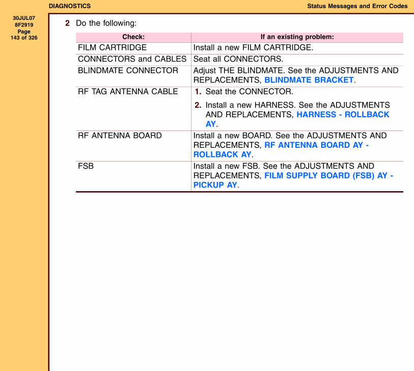
DIAGNOSTICS Status Messages and Error Codes
30JUL078F2919 Page
143 of 326
2 Do the following:
Check: If an existing problem:
FILM CARTRIDGE Install a new FILM CARTRIDGE.CONNECTORS and CABLES Seat all CONNECTORS.BLINDMATE CONNECTOR Adjust THE BLINDMATE. See the ADJUSTMENTS AND
REPLACEMENTS, BLINDMATE BRACKET.RF TAG ANTENNA CABLE 1. Seat the CONNECTOR.
2. Install a new HARNESS. See the ADJUSTMENTS AND REPLACEMENTS, HARNESS - ROLLBACK AY.
RF ANTENNA BOARD Install a new BOARD. See the ADJUSTMENTS AND REPLACEMENTS, RF ANTENNA BOARD AY - ROLLBACK AY.
FSB Install a new FSB. See the ADJUSTMENTS AND REPLACEMENTS, FILM SUPPLY BOARD (FSB) AY - PICKUP AY.
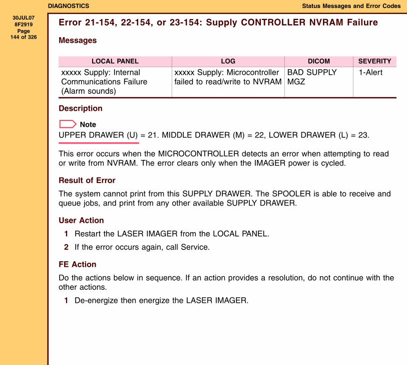
DIAGNOSTICS Status Messages and Error Codes
30JUL078F2919 Page
144 of 326
Error 21-154, 22-154, or 23-154: Supply CONTROLLER NVRAM Failure
Messages
Description
NoteUPPER DRAWER (U) = 21. MIDDLE DRAWER (M) = 22, LOWER DRAWER (L) = 23.
This error occurs when the MICROCONTROLLER detects an error when attempting to read or write from NVRAM. The error clears only when the IMAGER power is cycled.
Result of Error
The system cannot print from this SUPPLY DRAWER. The SPOOLER is able to receive and queue jobs, and print from any other available SUPPLY DRAWER.
User Action
1 Restart the LASER IMAGER from the LOCAL PANEL.
2 If the error occurs again, call Service.
FE Action
Do the actions below in sequence. If an action provides a resolution, do not continue with the other actions.
1 De-energize then energize the LASER IMAGER.
LOCAL PANEL LOG DICOM SEVERITY
xxxxx Supply: Internal Communications Failure(Alarm sounds)
xxxxx Supply: Microcontroller failed to read/write to NVRAM
BAD SUPPLY MGZ
1-Alert

DIAGNOSTICS Status Messages and Error Codes
30JUL078F2919 Page
145 of 326
2 Do the following:
Check: If an existing problem:
FILM CARTRIDGE Install a new FILM CARTRIDGE.CONNECTORS and CABLES Seat all CONNECTORS.BLINDMATE CONNECTOR Adjust THE BLINDMATE. See the ADJUSTMENTS AND
REPLACEMENTS, BLINDMATE BRACKET.RF TAG ANTENNA CABLE 1. Seat the CONNECTOR.
2. Install a new HARNESS. See the ADJUSTMENTS AND REPLACEMENTS, HARNESS - ROLLBACK AY.
RF ANTENNA BOARD Install a new BOARD. See the ADJUSTMENTS AND REPLACEMENTS, RF ANTENNA BOARD AY - ROLLBACK AY.
FSB Install a new FSB. See the ADJUSTMENTS AND REPLACEMENTS, FILM SUPPLY BOARD (FSB) AY - PICKUP AY.
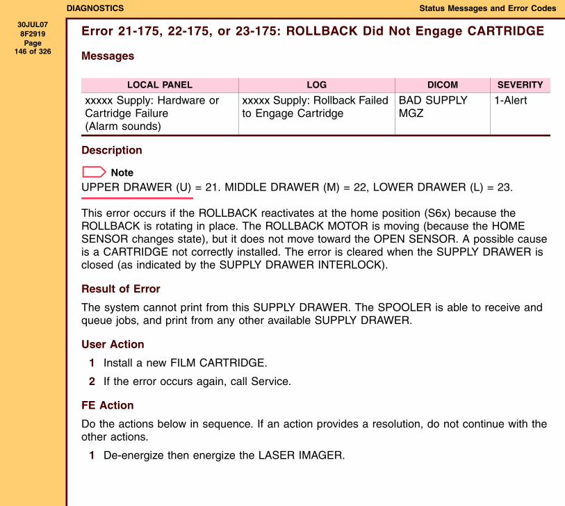
DIAGNOSTICS Status Messages and Error Codes
30JUL078F2919 Page
146 of 326
Error 21-175, 22-175, or 23-175: ROLLBACK Did Not Engage CARTRIDGE
Messages
Description
NoteUPPER DRAWER (U) = 21. MIDDLE DRAWER (M) = 22, LOWER DRAWER (L) = 23.
This error occurs if the ROLLBACK reactivates at the home position (S6x) because the ROLLBACK is rotating in place. The ROLLBACK MOTOR is moving (because the HOME SENSOR changes state), but it does not move toward the OPEN SENSOR. A possible cause is a CARTRIDGE not correctly installed. The error is cleared when the SUPPLY DRAWER is closed (as indicated by the SUPPLY DRAWER INTERLOCK).
Result of Error
The system cannot print from this SUPPLY DRAWER. The SPOOLER is able to receive and queue jobs, and print from any other available SUPPLY DRAWER.
User Action
1 Install a new FILM CARTRIDGE.
2 If the error occurs again, call Service.
FE Action
Do the actions below in sequence. If an action provides a resolution, do not continue with the other actions.
1 De-energize then energize the LASER IMAGER.
LOCAL PANEL LOG DICOM SEVERITY
xxxxx Supply: Hardware or Cartridge Failure (Alarm sounds)
xxxxx Supply: Rollback Failed to Engage Cartridge
BAD SUPPLY MGZ
1-Alert
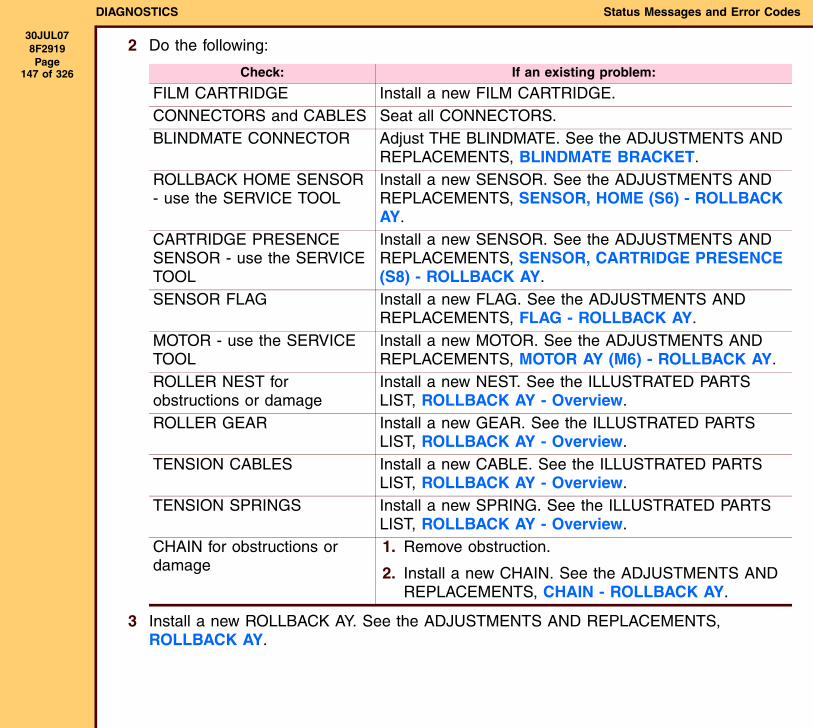
DIAGNOSTICS Status Messages and Error Codes
30JUL078F2919 Page
147 of 326
2 Do the following:
3 Install a new ROLLBACK AY. See the ADJUSTMENTS AND REPLACEMENTS, ROLLBACK AY.
Check: If an existing problem:
FILM CARTRIDGE Install a new FILM CARTRIDGE.CONNECTORS and CABLES Seat all CONNECTORS.BLINDMATE CONNECTOR Adjust THE BLINDMATE. See the ADJUSTMENTS AND
REPLACEMENTS, BLINDMATE BRACKET.ROLLBACK HOME SENSOR - use the SERVICE TOOL
Install a new SENSOR. See the ADJUSTMENTS AND REPLACEMENTS, SENSOR, HOME (S6) - ROLLBACK AY.
CARTRIDGE PRESENCE SENSOR - use the SERVICE TOOL
Install a new SENSOR. See the ADJUSTMENTS AND REPLACEMENTS, SENSOR, CARTRIDGE PRESENCE (S8) - ROLLBACK AY.
SENSOR FLAG Install a new FLAG. See the ADJUSTMENTS AND REPLACEMENTS, FLAG - ROLLBACK AY.
MOTOR - use the SERVICE TOOL
Install a new MOTOR. See the ADJUSTMENTS AND REPLACEMENTS, MOTOR AY (M6) - ROLLBACK AY.
ROLLER NEST for obstructions or damage
Install a new NEST. See the ILLUSTRATED PARTS LIST, ROLLBACK AY - Overview.
ROLLER GEAR Install a new GEAR. See the ILLUSTRATED PARTS LIST, ROLLBACK AY - Overview.
TENSION CABLES Install a new CABLE. See the ILLUSTRATED PARTS LIST, ROLLBACK AY - Overview.
TENSION SPRINGS Install a new SPRING. See the ILLUSTRATED PARTS LIST, ROLLBACK AY - Overview.
CHAIN for obstructions or damage
1. Remove obstruction.
2. Install a new CHAIN. See the ADJUSTMENTS AND REPLACEMENTS, CHAIN - ROLLBACK AY.
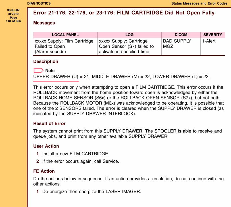
DIAGNOSTICS Status Messages and Error Codes
30JUL078F2919 Page
148 of 326
Error 21-176, 22-176, or 23-176: FILM CARTRIDGE Did Not Open Fully
Messages
Description
NoteUPPER DRAWER (U) = 21. MIDDLE DRAWER (M) = 22, LOWER DRAWER (L) = 23.
This error occurs only when attempting to open a FILM CARTRIDGE. This error occurs if the ROLLBACK movement from the home position toward open is acknowledged by either the ROLLBACK HOME SENSOR (S6x) or the ROLLBACK OPEN SENSOR (S7x), but not both. Because the ROLLBACK MOTOR (M6x) was acknowledged to be operating, it is possible that one of the 2 SENSORS failed. The error is cleared when the SUPPLY DRAWER is closed (as indicated by the SUPPLY DRAWER INTERLOCK).
Result of Error
The system cannot print from this SUPPLY DRAWER. The SPOOLER is able to receive and queue jobs, and print from any other available SUPPLY DRAWER.
User Action
1 Install a new FILM CARTRIDGE.
2 If the error occurs again, call Service.
FE Action
Do the actions below in sequence. If an action provides a resolution, do not continue with the other actions.
1 De-energize then energize the LASER IMAGER.
LOCAL PANEL LOG DICOM SEVERITY
xxxxx Supply: Film Cartridge Failed to Open (Alarm sounds)
xxxxx Supply: Cartridge Open Sensor (S7) failed to activate in specified time
BAD SUPPLY MGZ
1-Alert
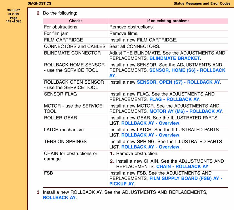
DIAGNOSTICS Status Messages and Error Codes
30JUL078F2919 Page
149 of 326
2 Do the following:
3 Install a new ROLLBACK AY. See the ADJUSTMENTS AND REPLACEMENTS, ROLLBACK AY.
Check: If an existing problem:
For obstructions Remove obstructions.For film jam Remove films.FILM CARTRIDGE Install a new FILM CARTRIDGE.CONNECTORS and CABLES Seat all CONNECTORS.BLINDMATE CONNECTOR Adjust THE BLINDMATE. See the ADJUSTMENTS AND
REPLACEMENTS, BLINDMATE BRACKET.ROLLBACK HOME SENSOR - use the SERVICE TOOL
Install a new SENSOR. See the ADJUSTMENTS AND REPLACEMENTS, SENSOR, HOME (S6) - ROLLBACK AY.
ROLLBACK OPEN SENSOR - use the SERVICE TOOL
Install a new SENSOR, OPEN (S7) - ROLLBACK AY.
SENSOR FLAG Install a new FLAG. See the ADJUSTMENTS AND REPLACEMENTS, FLAG - ROLLBACK AY.
MOTOR - use the SERVICE TOOL
Install a new MOTOR. See the ADJUSTMENTS AND REPLACEMENTS, MOTOR AY (M6) - ROLLBACK AY.
ROLLER GEAR Install a new GEAR. See the ILLUSTRATED PARTS LIST, ROLLBACK AY - Overview.
LATCH mechanism Install a new LATCH. See the ILLUSTRATED PARTS LIST, ROLLBACK AY - Overview.
TENSION SPRINGS Install a new SPRING. See the ILLUSTRATED PARTS LIST, ROLLBACK AY - Overview.
CHAIN for obstructions or damage
1. Remove obstruction.
2. Install a new CHAIN. See the ADJUSTMENTS AND REPLACEMENTS, CHAIN - ROLLBACK AY.
FSB Install a new FSB. See the ADJUSTMENTS AND REPLACEMENTS, FILM SUPPLY BOARD (FSB) AY - PICKUP AY.
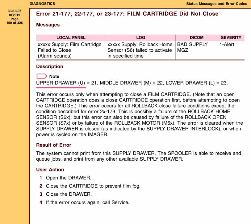
DIAGNOSTICS Status Messages and Error Codes
30JUL078F2919 Page
150 of 326
Error 21-177, 22-177, or 23-177: FILM CARTRIDGE Did Not Close
Messages
Description
NoteUPPER DRAWER (U) = 21. MIDDLE DRAWER (M) = 22, LOWER DRAWER (L) = 23.
This error occurs only when attempting to close a FILM CARTRIDGE. (Note that an open CARTRIDGE operation does a close CARTRIDGE operation first, before attempting to open the CARTRIDGE.) This error occurs for all ROLLBACK close failure conditions except the condition described for error 2x-179. This is possibly a failure of the ROLLBACK HOME SENSOR (S6x), but this error can also be caused by failure of the ROLLBACK OPEN SENSOR (S7x) or by failure of the ROLLBACK MOTOR (M6x). The error is cleared when the SUPPLY DRAWER is closed (as indicated by the SUPPLY DRAWER INTERLOCK), or when power is cycled on the IMAGER.
Result of Error
The system cannot print from this SUPPLY DRAWER. The SPOOLER is able to receive and queue jobs, and print from any other available SUPPLY DRAWER.
User Action
1 Open the DRAWER.
2 Close the CARTRIDGE to prevent film fog.
3 Close the DRAWER.
4 If the error occurs again, call Service.
LOCAL PANEL LOG DICOM SEVERITY
xxxxx Supply: Film Cartridge Failed to Close (Alarm sounds)
xxxxx Supply: Rollback Home Sensor (S6) failed to activate in specified time
BAD SUPPLY MGZ
1-Alert
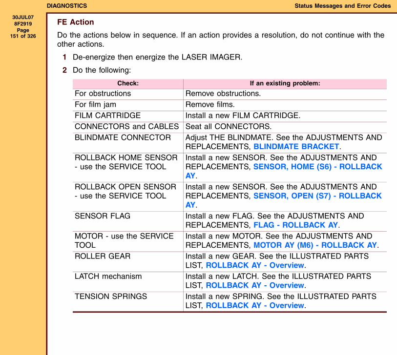
DIAGNOSTICS Status Messages and Error Codes
30JUL078F2919 Page
151 of 326
FE Action
Do the actions below in sequence. If an action provides a resolution, do not continue with the other actions.
1 De-energize then energize the LASER IMAGER.
2 Do the following:
Check: If an existing problem:
For obstructions Remove obstructions.For film jam Remove films.FILM CARTRIDGE Install a new FILM CARTRIDGE.CONNECTORS and CABLES Seat all CONNECTORS.BLINDMATE CONNECTOR Adjust THE BLINDMATE. See the ADJUSTMENTS AND
REPLACEMENTS, BLINDMATE BRACKET.ROLLBACK HOME SENSOR - use the SERVICE TOOL
Install a new SENSOR. See the ADJUSTMENTS AND REPLACEMENTS, SENSOR, HOME (S6) - ROLLBACK AY.
ROLLBACK OPEN SENSOR - use the SERVICE TOOL
Install a new SENSOR. See the ADJUSTMENTS AND REPLACEMENTS, SENSOR, OPEN (S7) - ROLLBACK AY.
SENSOR FLAG Install a new FLAG. See the ADJUSTMENTS AND REPLACEMENTS, FLAG - ROLLBACK AY.
MOTOR - use the SERVICE TOOL
Install a new MOTOR. See the ADJUSTMENTS AND REPLACEMENTS, MOTOR AY (M6) - ROLLBACK AY.
ROLLER GEAR Install a new GEAR. See the ILLUSTRATED PARTS LIST, ROLLBACK AY - Overview.
LATCH mechanism Install a new LATCH. See the ILLUSTRATED PARTS LIST, ROLLBACK AY - Overview.
TENSION SPRINGS Install a new SPRING. See the ILLUSTRATED PARTS LIST, ROLLBACK AY - Overview.
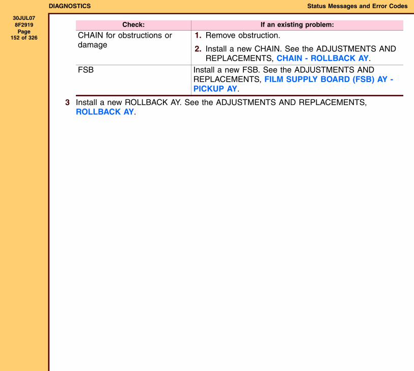
DIAGNOSTICS Status Messages and Error Codes
30JUL078F2919 Page
152 of 326
3 Install a new ROLLBACK AY. See the ADJUSTMENTS AND REPLACEMENTS, ROLLBACK AY.
CHAIN for obstructions or damage
1. Remove obstruction.
2. Install a new CHAIN. See the ADJUSTMENTS AND REPLACEMENTS, CHAIN - ROLLBACK AY.
FSB Install a new FSB. See the ADJUSTMENTS AND REPLACEMENTS, FILM SUPPLY BOARD (FSB) AY - PICKUP AY.
Check: If an existing problem:
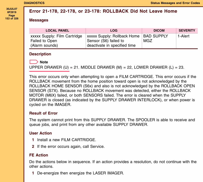
DIAGNOSTICS Status Messages and Error Codes
30JUL078F2919 Page
153 of 326
Error 21-178, 22-178, or 23-178: ROLLBACK Did Not Leave Home
Messages
Description
NoteUPPER DRAWER (U) = 21. MIDDLE DRAWER (M) = 22, LOWER DRAWER (L) = 23.
This error occurs only when attempting to open a FILM CARTRIDGE. This error occurs if the ROLLBACK movement from the home position toward open is not acknowledged by the ROLLBACK HOME SENSOR (S6x) and also is not acknowledged by the ROLLBACK OPEN SENSOR (S7X). Because no ROLLBACK movement was detected, either the ROLLBACK MOTOR (M6X) failed, or both SENSORS failed. The error is cleared when the SUPPLY DRAWER is closed (as indicated by the SUPPLY DRAWER INTERLOCK), or when power is cycled on the IMAGER.
Result of Error
The system cannot print from this SUPPLY DRAWER. The SPOOLER is able to receive and queue jobs, and print from any other available SUPPLY DRAWER.
User Action
1 Install a new FILM CARTRIDGE.
2 If the error occurs again, call Service.
FE Action
Do the actions below in sequence. If an action provides a resolution, do not continue with the other actions.
1 De-energize then energize the LASER IMAGER.
LOCAL PANEL LOG DICOM SEVERITY
xxxxx Supply: Film Cartridge Failed to Open (Alarm sounds)
xxxxx Supply: Rollback Home Sensor (S6) failed to deactivate in specified time
BAD SUPPLY MGZ
1-Alert
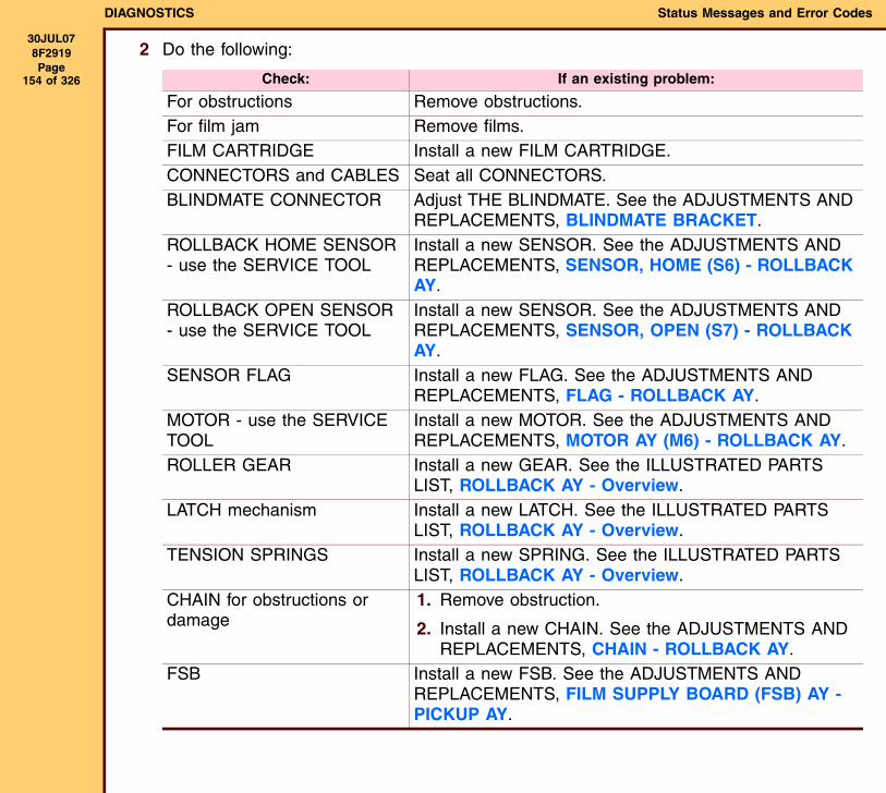
DIAGNOSTICS Status Messages and Error Codes
30JUL078F2919 Page
154 of 326
2 Do the following:
Check: If an existing problem:
For obstructions Remove obstructions.For film jam Remove films.FILM CARTRIDGE Install a new FILM CARTRIDGE.CONNECTORS and CABLES Seat all CONNECTORS.BLINDMATE CONNECTOR Adjust THE BLINDMATE. See the ADJUSTMENTS AND
REPLACEMENTS, BLINDMATE BRACKET.ROLLBACK HOME SENSOR - use the SERVICE TOOL
Install a new SENSOR. See the ADJUSTMENTS AND REPLACEMENTS, SENSOR, HOME (S6) - ROLLBACK AY.
ROLLBACK OPEN SENSOR - use the SERVICE TOOL
Install a new SENSOR. See the ADJUSTMENTS AND REPLACEMENTS, SENSOR, OPEN (S7) - ROLLBACK AY.
SENSOR FLAG Install a new FLAG. See the ADJUSTMENTS AND REPLACEMENTS, FLAG - ROLLBACK AY.
MOTOR - use the SERVICE TOOL
Install a new MOTOR. See the ADJUSTMENTS AND REPLACEMENTS, MOTOR AY (M6) - ROLLBACK AY.
ROLLER GEAR Install a new GEAR. See the ILLUSTRATED PARTS LIST, ROLLBACK AY - Overview.
LATCH mechanism Install a new LATCH. See the ILLUSTRATED PARTS LIST, ROLLBACK AY - Overview.
TENSION SPRINGS Install a new SPRING. See the ILLUSTRATED PARTS LIST, ROLLBACK AY - Overview.
CHAIN for obstructions or damage
1. Remove obstruction.
2. Install a new CHAIN. See the ADJUSTMENTS AND REPLACEMENTS, CHAIN - ROLLBACK AY.
FSB Install a new FSB. See the ADJUSTMENTS AND REPLACEMENTS, FILM SUPPLY BOARD (FSB) AY - PICKUP AY.
DIAGNOSTICS Status Messages and Error Codes
30JUL078F2919 Page
155 of 326
3 Install a new ROLLBACK AY. See the ADJUSTMENTS AND REPLACEMENTS, ROLLBACK AY.
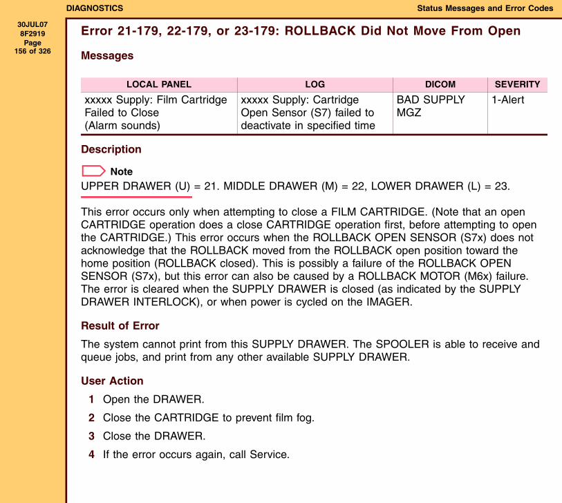
DIAGNOSTICS Status Messages and Error Codes
30JUL078F2919 Page
156 of 326
Error 21-179, 22-179, or 23-179: ROLLBACK Did Not Move From Open
Messages
Description
NoteUPPER DRAWER (U) = 21. MIDDLE DRAWER (M) = 22, LOWER DRAWER (L) = 23.
This error occurs only when attempting to close a FILM CARTRIDGE. (Note that an open CARTRIDGE operation does a close CARTRIDGE operation first, before attempting to open the CARTRIDGE.) This error occurs when the ROLLBACK OPEN SENSOR (S7x) does not acknowledge that the ROLLBACK moved from the ROLLBACK open position toward the home position (ROLLBACK closed). This is possibly a failure of the ROLLBACK OPEN SENSOR (S7x), but this error can also be caused by a ROLLBACK MOTOR (M6x) failure. The error is cleared when the SUPPLY DRAWER is closed (as indicated by the SUPPLY DRAWER INTERLOCK), or when power is cycled on the IMAGER.
Result of Error
The system cannot print from this SUPPLY DRAWER. The SPOOLER is able to receive and queue jobs, and print from any other available SUPPLY DRAWER.
User Action
1 Open the DRAWER.
2 Close the CARTRIDGE to prevent film fog.
3 Close the DRAWER.
4 If the error occurs again, call Service.
LOCAL PANEL LOG DICOM SEVERITY
xxxxx Supply: Film Cartridge Failed to Close (Alarm sounds)
xxxxx Supply: Cartridge Open Sensor (S7) failed to deactivate in specified time
BAD SUPPLY MGZ
1-Alert

DIAGNOSTICS Status Messages and Error Codes
30JUL078F2919 Page
157 of 326
FE Action
Do the actions below in sequence. If an action provides a resolution, do not continue with the other actions.
1 De-energize then energize the LASER IMAGER.
2 Do the following:
Check: If an existing problem:
For obstructions Remove obstructions.For film jam Remove films.FILM CARTRIDGE Install a new FILM CARTRIDGE.CONNECTORS and CABLES Seat all CONNECTORS.BLINDMATE CONNECTOR Adjust THE BLINDMATE. See the ADJUSTMENTS AND
REPLACEMENTS, BLINDMATE BRACKET.ROLLBACK HOME SENSOR - use the SERVICE TOOL
Install a new SENSOR. See the ADJUSTMENTS AND REPLACEMENTS, SENSOR, HOME (S6) - ROLLBACK AY.
ROLLBACK OPEN SENSOR - use the SERVICE TOOL
Install a new SENSOR. See the ADJUSTMENTS AND REPLACEMENTS, SENSOR, OPEN (S7) - ROLLBACK AY.
SENSOR FLAG Install a new FLAG. See the ADJUSTMENTS AND REPLACEMENTS, FLAG - ROLLBACK AY.
MOTOR - use the SERVICE TOOL
Install a new MOTOR. See the ADJUSTMENTS AND REPLACEMENTS, MOTOR AY (M6) - ROLLBACK AY.
ROLLER GEAR Install a new GEAR. See the ILLUSTRATED PARTS LIST, ROLLBACK AY - Overview.
LATCH mechanism Install a new LATCH. See the ILLUSTRATED PARTS LIST, ROLLBACK AY - Overview.
TENSION SPRINGS Install a new SPRING. See the ILLUSTRATED PARTS LIST, ROLLBACK AY - Overview.

DIAGNOSTICS Status Messages and Error Codes
30JUL078F2919 Page
158 of 326
3 Install a new ROLLBACK AY. See the ADJUSTMENTS AND REPLACEMENTS, ROLLBACK AY.
CHAIN for obstructions or damage
1. Remove obstruction.
2. Install a new CHAIN. See the ADJUSTMENTS AND REPLACEMENTS, CHAIN - ROLLBACK AY.
FSB Install a new FSB. See the ADJUSTMENTS AND REPLACEMENTS, FILM SUPPLY BOARD (FSB) AY - PICKUP AY.
Check: If an existing problem:
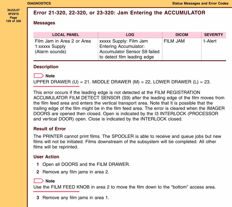
DIAGNOSTICS Status Messages and Error Codes
30JUL078F2919 Page
159 of 326
Error 21-320, 22-320, or 23-320: Jam Entering the ACCUMULATOR
Messages
Description
NoteUPPER DRAWER (U) = 21. MIDDLE DRAWER (M) = 22, LOWER DRAWER (L) = 23.
This error occurs if the leading edge is not detected at the FILM REGISTRATION ACCUMULATOR FILM DETECT SENSOR (S9) after the leading edge of the film moves from the film feed area and enters the vertical transport area. Note that it is possible that the trailing edge of the film might be in the film feed area. The error is cleared when the IMAGER DOORS are opened then closed. Open is indicated by the I3 INTERLOCK (PROCESSOR and vertical DOOR) open. Close is indicated by the INTERLOCK closed.
Result of Error
The PRINTER cannot print films. The SPOOLER is able to receive and queue jobs but new films will not be initiated. Films downstream of the subsystem will be completed. All other films will be reprinted.
User Action
1 Open all DOORS and the FILM DRAWER.
2 Remove any film jams in area 2.
NoteUse the FILM FEED KNOB in area 2 to move the film down to the “bottom” access area.
3 Remove any film jams in area 1.
LOCAL PANEL LOG DICOM SEVERITY
Film Jam in Area 2 or Area 1:xxxxx Supply (Alarm sounds)
xxxxx Supply: Film Jam Entering Accumulator: Accumulator Sensor S9 failed to detect film leading edge
FILM JAM 1-Alert
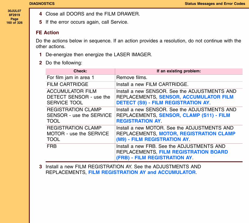
DIAGNOSTICS Status Messages and Error Codes
30JUL078F2919 Page
160 of 326
4 Close all DOORS and the FILM DRAWER.
5 If the error occurs again, call Service.
FE Action
Do the actions below in sequence. If an action provides a resolution, do not continue with the other actions.
1 De-energize then energize the LASER IMAGER.
2 Do the following:
3 Install a new FILM REGISTRATION AY. See the ADJUSTMENTS AND REPLACEMENTS, FILM REGISTRATION AY and ACCUMULATOR.
Check: If an existing problem:
For film jam in area 1 Remove films.FILM CARTRIDGE Install a new FILM CARTRIDGE.ACCUMULATOR FILM DETECT SENSOR - use the SERVICE TOOL
Install a new SENSOR. See the ADJUSTMENTS AND REPLACEMENTS, SENSOR, ACCUMULATOR FILM DETECT (S9) - FILM REGISTRATION AY.
REGISTRATION CLAMP SENSOR - use the SERVICE TOOL
Install a new SENSOR. See the ADJUSTMENTS AND REPLACEMENTS, SENSOR, CLAMP (S11) - FILM REGISTRATION AY.
REGISTRATION CLAMP MOTOR - use the SERVICE TOOL
Install a new MOTOR. See the ADJUSTMENTS AND REPLACEMENTS, MOTOR, REGISTRATION CLAMP (M9) - FILM REGISTRATION AY.
FRB Install a new FRB. See the ADJUSTMENTS AND REPLACEMENTS, FILM REGISTRATION BOARD (FRB) - FILM REGISTRATION AY.
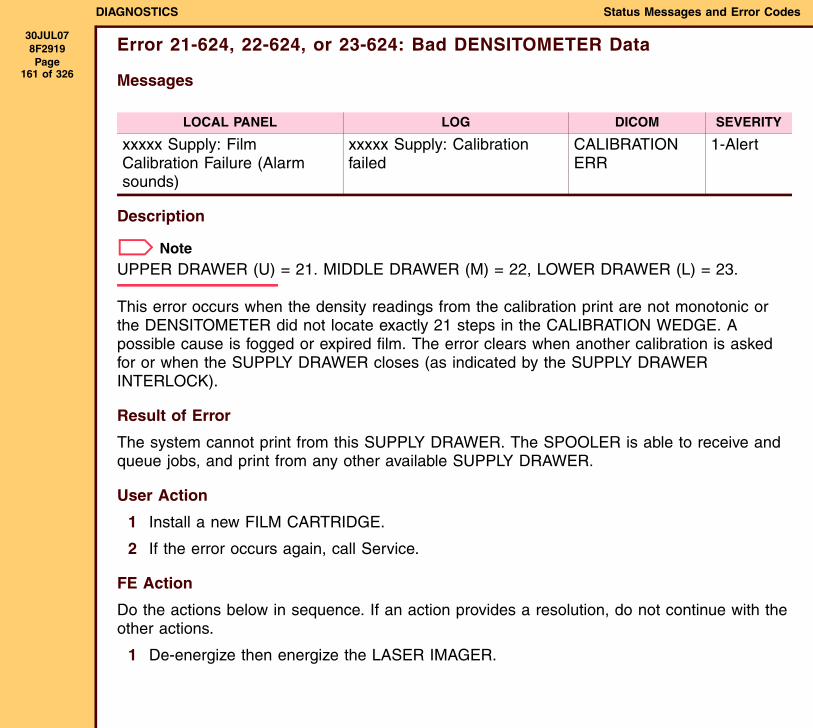
DIAGNOSTICS Status Messages and Error Codes
30JUL078F2919 Page
161 of 326
Error 21-624, 22-624, or 23-624: Bad DENSITOMETER Data
Messages
Description
NoteUPPER DRAWER (U) = 21. MIDDLE DRAWER (M) = 22, LOWER DRAWER (L) = 23.
This error occurs when the density readings from the calibration print are not monotonic or the DENSITOMETER did not locate exactly 21 steps in the CALIBRATION WEDGE. A possible cause is fogged or expired film. The error clears when another calibration is asked for or when the SUPPLY DRAWER closes (as indicated by the SUPPLY DRAWER INTERLOCK).
Result of Error
The system cannot print from this SUPPLY DRAWER. The SPOOLER is able to receive and queue jobs, and print from any other available SUPPLY DRAWER.
User Action
1 Install a new FILM CARTRIDGE.
2 If the error occurs again, call Service.
FE Action
Do the actions below in sequence. If an action provides a resolution, do not continue with the other actions.
1 De-energize then energize the LASER IMAGER.
LOCAL PANEL LOG DICOM SEVERITY
xxxxx Supply: Film Calibration Failure (Alarm sounds)
xxxxx Supply: Calibration failed
CALIBRATION ERR
1-Alert
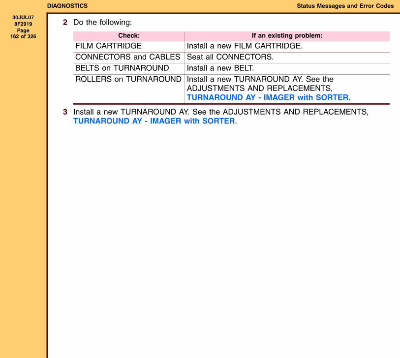
DIAGNOSTICS Status Messages and Error Codes
30JUL078F2919 Page
162 of 326
2 Do the following:
3 Install a new TURNAROUND AY. See the ADJUSTMENTS AND REPLACEMENTS, TURNAROUND AY - IMAGER with SORTER.
Check: If an existing problem:
FILM CARTRIDGE Install a new FILM CARTRIDGE.CONNECTORS and CABLES Seat all CONNECTORS.BELTS on TURNAROUND Install a new BELT.ROLLERS on TURNAROUND Install a new TURNAROUND AY. See the
ADJUSTMENTS AND REPLACEMENTS, TURNAROUND AY - IMAGER with SORTER.
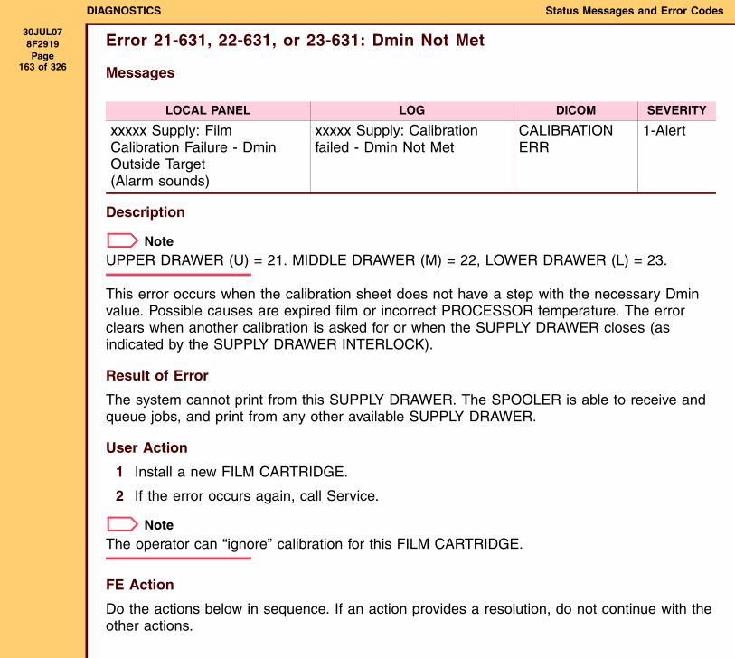
DIAGNOSTICS Status Messages and Error Codes
30JUL078F2919 Page
163 of 326
Error 21-631, 22-631, or 23-631: Dmin Not Met
Messages
Description
NoteUPPER DRAWER (U) = 21. MIDDLE DRAWER (M) = 22, LOWER DRAWER (L) = 23.
This error occurs when the calibration sheet does not have a step with the necessary Dmin value. Possible causes are expired film or incorrect PROCESSOR temperature. The error clears when another calibration is asked for or when the SUPPLY DRAWER closes (as indicated by the SUPPLY DRAWER INTERLOCK).
Result of Error
The system cannot print from this SUPPLY DRAWER. The SPOOLER is able to receive and queue jobs, and print from any other available SUPPLY DRAWER.
User Action
1 Install a new FILM CARTRIDGE.
2 If the error occurs again, call Service.
NoteThe operator can “ignore” calibration for this FILM CARTRIDGE.
FE Action
Do the actions below in sequence. If an action provides a resolution, do not continue with the other actions.
LOCAL PANEL LOG DICOM SEVERITY
xxxxx Supply: Film Calibration Failure - Dmin Outside Target(Alarm sounds)
xxxxx Supply: Calibration failed - Dmin Not Met
CALIBRATION ERR
1-Alert
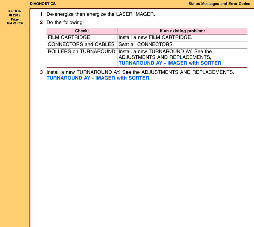
DIAGNOSTICS Status Messages and Error Codes
30JUL078F2919 Page
164 of 326
1 De-energize then energize the LASER IMAGER.
2 Do the following:
3 Install a new TURNAROUND AY. See the ADJUSTMENTS AND REPLACEMENTS, TURNAROUND AY - IMAGER with SORTER.
Check: If an existing problem:
FILM CARTRIDGE Install a new FILM CARTRIDGE.CONNECTORS and CABLES Seat all CONNECTORS.ROLLERS on TURNAROUND Install a new TURNAROUND AY. See the
ADJUSTMENTS AND REPLACEMENTS, TURNAROUND AY - IMAGER with SORTER.
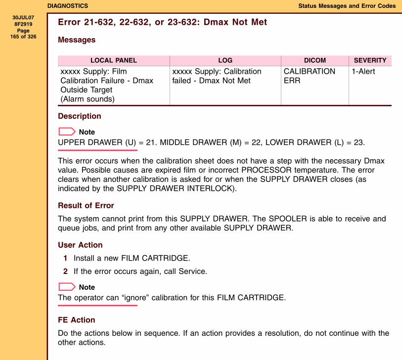
DIAGNOSTICS Status Messages and Error Codes
30JUL078F2919 Page
165 of 326
Error 21-632, 22-632, or 23-632: Dmax Not Met
Messages
Description
NoteUPPER DRAWER (U) = 21. MIDDLE DRAWER (M) = 22, LOWER DRAWER (L) = 23.
This error occurs when the calibration sheet does not have a step with the necessary Dmax value. Possible causes are expired film or incorrect PROCESSOR temperature. The error clears when another calibration is asked for or when the SUPPLY DRAWER closes (as indicated by the SUPPLY DRAWER INTERLOCK).
Result of Error
The system cannot print from this SUPPLY DRAWER. The SPOOLER is able to receive and queue jobs, and print from any other available SUPPLY DRAWER.
User Action
1 Install a new FILM CARTRIDGE.
2 If the error occurs again, call Service.
NoteThe operator can “ignore” calibration for this FILM CARTRIDGE.
FE Action
Do the actions below in sequence. If an action provides a resolution, do not continue with the other actions.
LOCAL PANEL LOG DICOM SEVERITY
xxxxx Supply: Film Calibration Failure - Dmax Outside Target (Alarm sounds)
xxxxx Supply: Calibration failed - Dmax Not Met
CALIBRATION ERR
1-Alert

DIAGNOSTICS Status Messages and Error Codes
30JUL078F2919 Page
166 of 326
1 De-energize then energize the LASER IMAGER.
2 Do the following:
3 Install a new TURNAROUND AY. See the ADJUSTMENTS AND REPLACEMENTS, TURNAROUND AY - IMAGER with SORTER.
Check: If an existing problem:
FILM CARTRIDGE Install a new FILM CARTRIDGE.CONNECTORS and CABLES Seat all CONNECTORS.ROLLERS on TURNAROUND Install a new TURNAROUND AY. See the
ADJUSTMENTS AND REPLACEMENTS, TURNAROUND AY - IMAGER with SORTER.
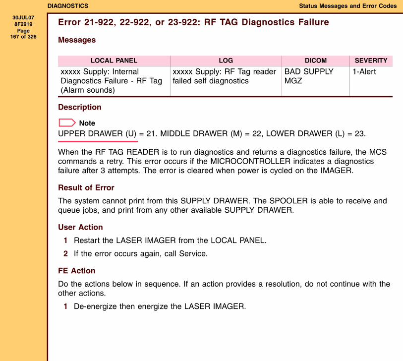
DIAGNOSTICS Status Messages and Error Codes
30JUL078F2919 Page
167 of 326
Error 21-922, 22-922, or 23-922: RF TAG Diagnostics Failure
Messages
Description
NoteUPPER DRAWER (U) = 21. MIDDLE DRAWER (M) = 22, LOWER DRAWER (L) = 23.
When the RF TAG READER is to run diagnostics and returns a diagnostics failure, the MCS commands a retry. This error occurs if the MICROCONTROLLER indicates a diagnostics failure after 3 attempts. The error is cleared when power is cycled on the IMAGER.
Result of Error
The system cannot print from this SUPPLY DRAWER. The SPOOLER is able to receive and queue jobs, and print from any other available SUPPLY DRAWER.
User Action
1 Restart the LASER IMAGER from the LOCAL PANEL.
2 If the error occurs again, call Service.
FE Action
Do the actions below in sequence. If an action provides a resolution, do not continue with the other actions.
1 De-energize then energize the LASER IMAGER.
LOCAL PANEL LOG DICOM SEVERITY
xxxxx Supply: Internal Diagnostics Failure - RF Tag (Alarm sounds)
xxxxx Supply: RF Tag reader failed self diagnostics
BAD SUPPLY MGZ
1-Alert
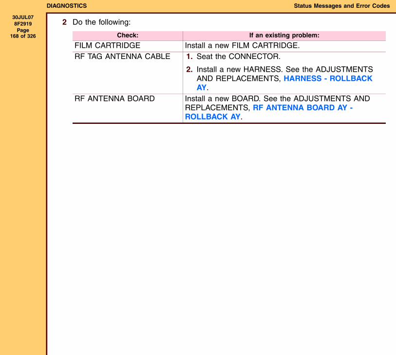
DIAGNOSTICS Status Messages and Error Codes
30JUL078F2919 Page
168 of 326
2 Do the following:
Check: If an existing problem:
FILM CARTRIDGE Install a new FILM CARTRIDGE.RF TAG ANTENNA CABLE 1. Seat the CONNECTOR.
2. Install a new HARNESS. See the ADJUSTMENTS AND REPLACEMENTS, HARNESS - ROLLBACK AY.
RF ANTENNA BOARD Install a new BOARD. See the ADJUSTMENTS AND REPLACEMENTS, RF ANTENNA BOARD AY - ROLLBACK AY.
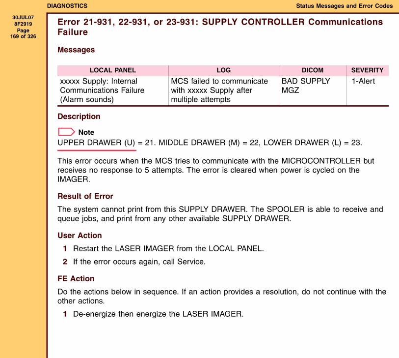
DIAGNOSTICS Status Messages and Error Codes
30JUL078F2919 Page
169 of 326
Error 21-931, 22-931, or 23-931: SUPPLY CONTROLLER Communications Failure
Messages
Description
NoteUPPER DRAWER (U) = 21. MIDDLE DRAWER (M) = 22, LOWER DRAWER (L) = 23.
This error occurs when the MCS tries to communicate with the MICROCONTROLLER but receives no response to 5 attempts. The error is cleared when power is cycled on the IMAGER.
Result of Error
The system cannot print from this SUPPLY DRAWER. The SPOOLER is able to receive and queue jobs, and print from any other available SUPPLY DRAWER.
User Action
1 Restart the LASER IMAGER from the LOCAL PANEL.
2 If the error occurs again, call Service.
FE Action
Do the actions below in sequence. If an action provides a resolution, do not continue with the other actions.
1 De-energize then energize the LASER IMAGER.
LOCAL PANEL LOG DICOM SEVERITY
xxxxx Supply: Internal Communications Failure (Alarm sounds)
MCS failed to communicate with xxxxx Supply after multiple attempts
BAD SUPPLY MGZ
1-Alert
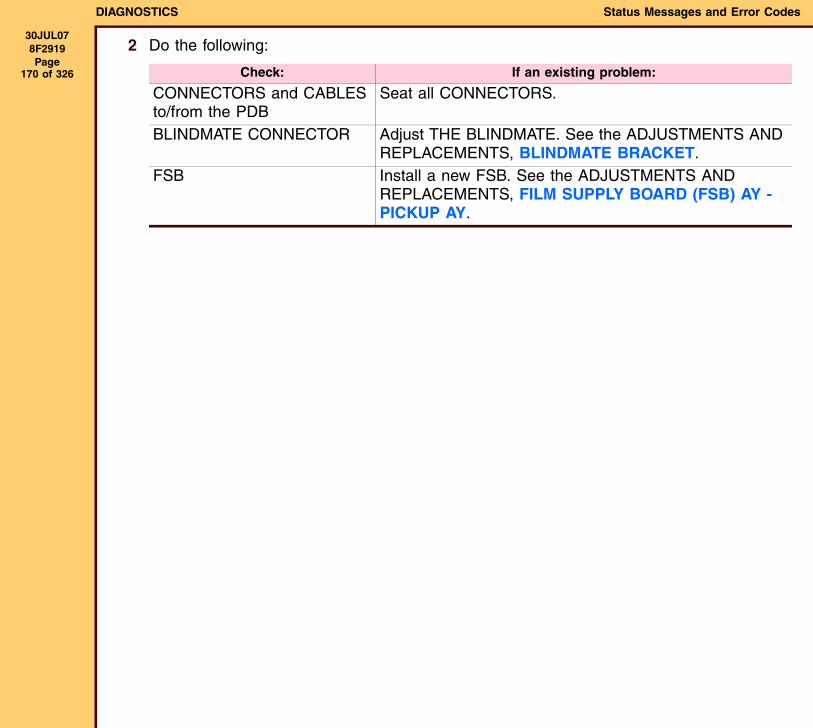
DIAGNOSTICS Status Messages and Error Codes
30JUL078F2919 Page
170 of 326
2 Do the following:
Check: If an existing problem:
CONNECTORS and CABLES to/from the PDB
Seat all CONNECTORS.
BLINDMATE CONNECTOR Adjust THE BLINDMATE. See the ADJUSTMENTS AND REPLACEMENTS, BLINDMATE BRACKET.
FSB Install a new FSB. See the ADJUSTMENTS AND REPLACEMENTS, FILM SUPPLY BOARD (FSB) AY - PICKUP AY.
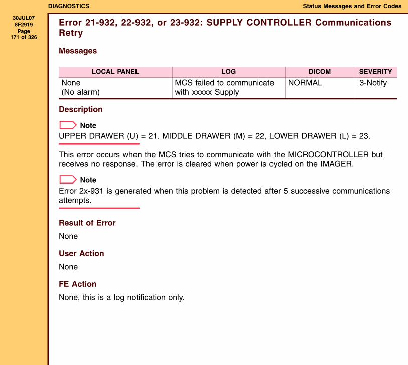
DIAGNOSTICS Status Messages and Error Codes
30JUL078F2919 Page
171 of 326
Error 21-932, 22-932, or 23-932: SUPPLY CONTROLLER Communications Retry
Messages
Description
NoteUPPER DRAWER (U) = 21. MIDDLE DRAWER (M) = 22, LOWER DRAWER (L) = 23.
This error occurs when the MCS tries to communicate with the MICROCONTROLLER but receives no response. The error is cleared when power is cycled on the IMAGER.
NoteError 2x-931 is generated when this problem is detected after 5 successive communications attempts.
Result of Error
None
User Action
None
FE Action
None, this is a log notification only.
LOCAL PANEL LOG DICOM SEVERITY
None(No alarm)
MCS failed to communicate with xxxxx Supply
NORMAL 3-Notify
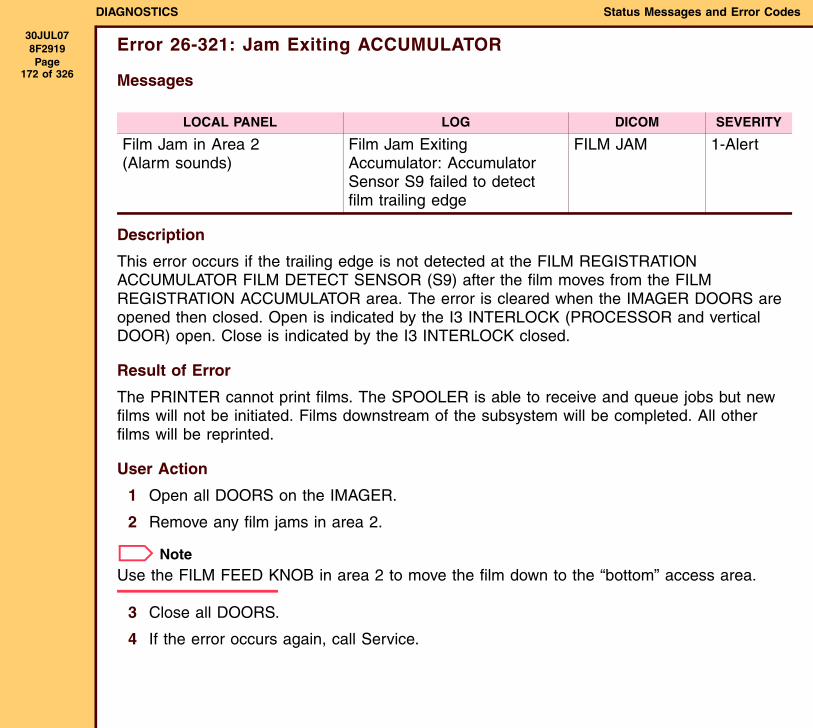
DIAGNOSTICS Status Messages and Error Codes
30JUL078F2919 Page
172 of 326
Error 26-321: Jam Exiting ACCUMULATOR
Messages
Description
This error occurs if the trailing edge is not detected at the FILM REGISTRATION ACCUMULATOR FILM DETECT SENSOR (S9) after the film moves from the FILM REGISTRATION ACCUMULATOR area. The error is cleared when the IMAGER DOORS are opened then closed. Open is indicated by the I3 INTERLOCK (PROCESSOR and vertical DOOR) open. Close is indicated by the I3 INTERLOCK closed.
Result of Error
The PRINTER cannot print films. The SPOOLER is able to receive and queue jobs but new films will not be initiated. Films downstream of the subsystem will be completed. All other films will be reprinted.
User Action
1 Open all DOORS on the IMAGER.
2 Remove any film jams in area 2.
NoteUse the FILM FEED KNOB in area 2 to move the film down to the “bottom” access area.
3 Close all DOORS.
4 If the error occurs again, call Service.
LOCAL PANEL LOG DICOM SEVERITY
Film Jam in Area 2(Alarm sounds)
Film Jam Exiting Accumulator: Accumulator Sensor S9 failed to detect film trailing edge
FILM JAM 1-Alert
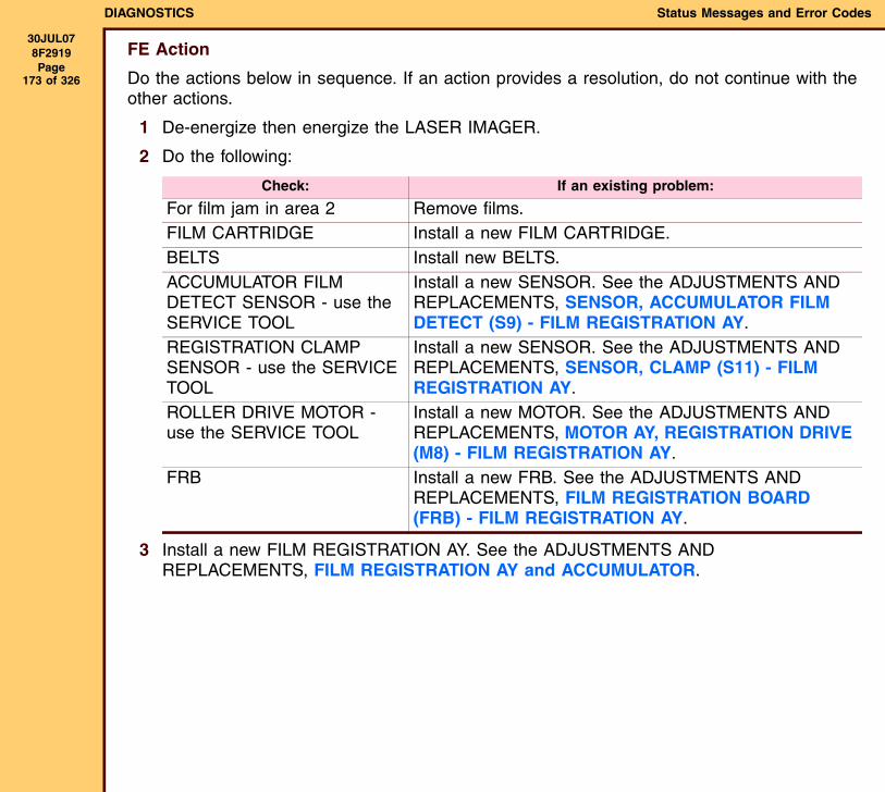
DIAGNOSTICS Status Messages and Error Codes
30JUL078F2919 Page
173 of 326
FE Action
Do the actions below in sequence. If an action provides a resolution, do not continue with the other actions.
1 De-energize then energize the LASER IMAGER.
2 Do the following:
3 Install a new FILM REGISTRATION AY. See the ADJUSTMENTS AND REPLACEMENTS, FILM REGISTRATION AY and ACCUMULATOR.
Check: If an existing problem:
For film jam in area 2 Remove films.FILM CARTRIDGE Install a new FILM CARTRIDGE.BELTS Install new BELTS.ACCUMULATOR FILM DETECT SENSOR - use the SERVICE TOOL
Install a new SENSOR. See the ADJUSTMENTS AND REPLACEMENTS, SENSOR, ACCUMULATOR FILM DETECT (S9) - FILM REGISTRATION AY.
REGISTRATION CLAMP SENSOR - use the SERVICE TOOL
Install a new SENSOR. See the ADJUSTMENTS AND REPLACEMENTS, SENSOR, CLAMP (S11) - FILM REGISTRATION AY.
ROLLER DRIVE MOTOR - use the SERVICE TOOL
Install a new MOTOR. See the ADJUSTMENTS AND REPLACEMENTS, MOTOR AY, REGISTRATION DRIVE (M8) - FILM REGISTRATION AY.
FRB Install a new FRB. See the ADJUSTMENTS AND REPLACEMENTS, FILM REGISTRATION BOARD (FRB) - FILM REGISTRATION AY.
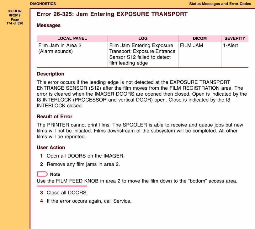
DIAGNOSTICS Status Messages and Error Codes
30JUL078F2919 Page
174 of 326
Error 26-325: Jam Entering EXPOSURE TRANSPORT
Messages
Description
This error occurs if the leading edge is not detected at the EXPOSURE TRANSPORT ENTRANCE SENSOR (S12) after the film moves from the FILM REGISTRATION area. The error is cleared when the IMAGER DOORS are opened then closed. Open is indicated by the I3 INTERLOCK (PROCESSOR and vertical DOOR) open. Close is indicated by the I3 INTERLOCK closed.
Result of Error
The PRINTER cannot print films. The SPOOLER is able to receive and queue jobs but new films will not be initiated. Films downstream of the subsystem will be completed. All other films will be reprinted.
User Action
1 Open all DOORS on the IMAGER.
2 Remove any film jams in area 2.
NoteUse the FILM FEED KNOB in area 2 to move the film down to the “bottom” access area.
3 Close all DOORS.
4 If the error occurs again, call Service.
LOCAL PANEL LOG DICOM SEVERITY
Film Jam in Area 2(Alarm sounds)
Film Jam Entering Exposure Transport: Exposure Entrance Sensor S12 failed to detect film leading edge
FILM JAM 1-Alert
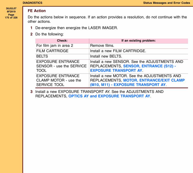
DIAGNOSTICS Status Messages and Error Codes
30JUL078F2919 Page
175 of 326
FE Action
Do the actions below in sequence. If an action provides a resolution, do not continue with the other actions.
1 De-energize then energize the LASER IMAGER.
2 Do the following:
3 Install a new EXPOSURE TRANSPORT AY. See the ADJUSTMENTS AND REPLACEMENTS, OPTICS AY and EXPOSURE TRANSPORT AY.
Check: If an existing problem:
For film jam in area 2 Remove films.FILM CARTRIDGE Install a new FILM CARTRIDGE.BELTS Install new BELTS.EXPOSURE ENTRANCE SENSOR - use the SERVICE TOOL
Install a new SENSOR. See the ADJUSTMENTS AND REPLACEMENTS, SENSOR, ENTRANCE (S12) - EXPOSURE TRANSPORT AY.
EXPOSURE ENTRANCE CLAMP MOTOR - use the SERVICE TOOL
Install a new MOTOR. See the ADJUSTMENTS AND REPLACEMENTS, MOTOR, ENTRANCE/EXIT CLAMP (M10, M11) - EXPOSURE TRANSPORT AY.
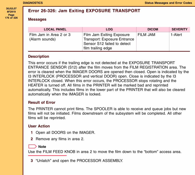
DIAGNOSTICS Status Messages and Error Codes
30JUL078F2919 Page
176 of 326
Error 26-326: Jam Exiting EXPOSURE TRANSPORT
Messages
Description
This error occurs if the trailing edge is not detected at the EXPOSURE TRANSPORT ENTRANCE SENSOR (S12) after the film moves from the FILM REGISTRATION area. The error is cleared when the IMAGER DOORS are opened then closed. Open is indicated by the I3 INTERLOCK (PROCESSOR and vertical DOOR) open. Close is indicated by the I3 INTERLOCK closed. When this error occurs, the PROCESSOR stops rotating and the HEATER is turned off. All films in the PRINTER will be marked bad and reprinted automatically. This includes films in the lower part of the PRINTER that will also be cleared automatically when the IMAGER is locked.
Result of Error
The PRINTER cannot print films. The SPOOLER is able to receive and queue jobs but new films will not be initiated. Films downstream of the subsystem will be completed. All other films will be reprinted.
User Action
1 Open all DOORS on the IMAGER.
2 Remove any films in area 2.
NoteUse the FILM FEED KNOB in area 2 to move the film down to the “bottom” access area.
3 “Unlatch” and open the PROCESSOR ASSEMBLY.
LOCAL PANEL LOG DICOM SEVERITY
Film Jam in Area 2 or 3(Alarm sounds)
Film Jam Exiting Exposure Transport: Exposure Entrance Sensor S12 failed to detect film trailing edge
FILM JAM 1-Alert
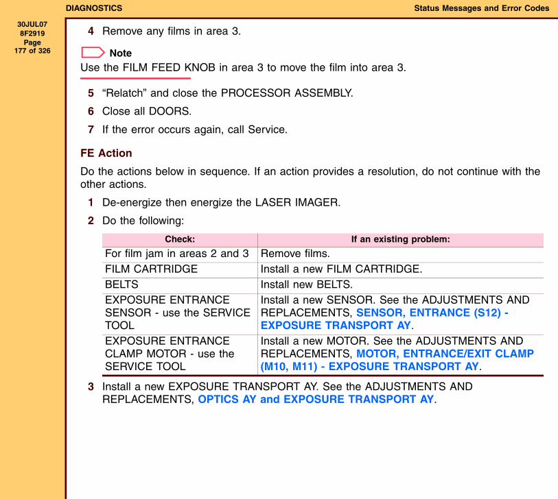
DIAGNOSTICS Status Messages and Error Codes
30JUL078F2919 Page
177 of 326
4 Remove any films in area 3.
NoteUse the FILM FEED KNOB in area 3 to move the film into area 3.
5 “Relatch” and close the PROCESSOR ASSEMBLY.
6 Close all DOORS.
7 If the error occurs again, call Service.
FE Action
Do the actions below in sequence. If an action provides a resolution, do not continue with the other actions.
1 De-energize then energize the LASER IMAGER.
2 Do the following:
3 Install a new EXPOSURE TRANSPORT AY. See the ADJUSTMENTS AND REPLACEMENTS, OPTICS AY and EXPOSURE TRANSPORT AY.
Check: If an existing problem:
For film jam in areas 2 and 3 Remove films.FILM CARTRIDGE Install a new FILM CARTRIDGE.BELTS Install new BELTS.EXPOSURE ENTRANCE SENSOR - use the SERVICE TOOL
Install a new SENSOR. See the ADJUSTMENTS AND REPLACEMENTS, SENSOR, ENTRANCE (S12) - EXPOSURE TRANSPORT AY.
EXPOSURE ENTRANCE CLAMP MOTOR - use the SERVICE TOOL
Install a new MOTOR. See the ADJUSTMENTS AND REPLACEMENTS, MOTOR, ENTRANCE/EXIT CLAMP (M10, M11) - EXPOSURE TRANSPORT AY.
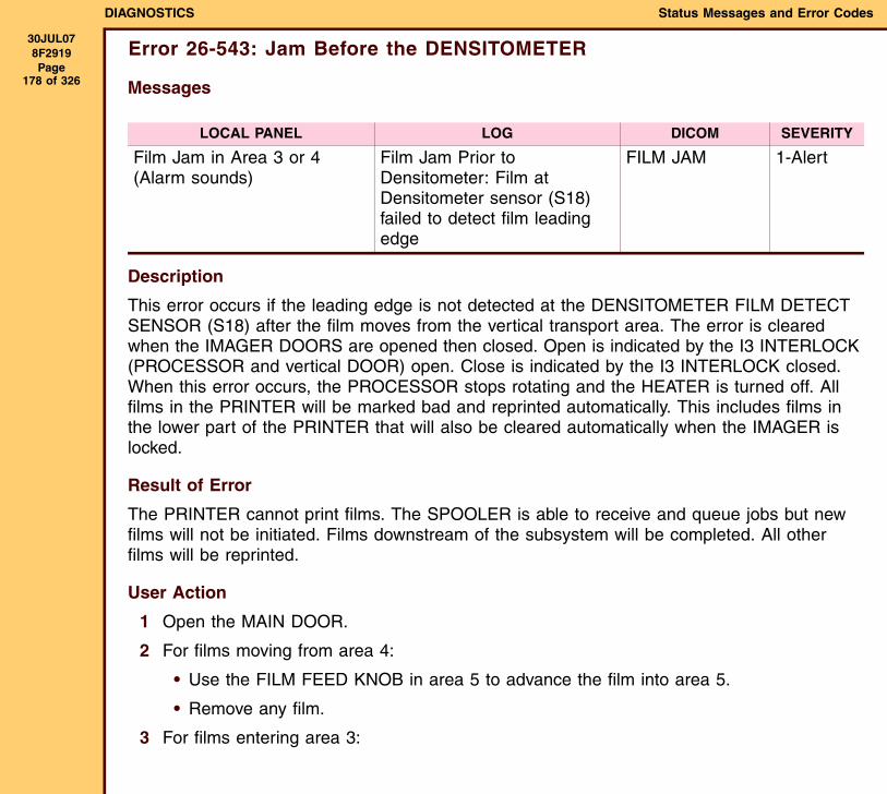
DIAGNOSTICS Status Messages and Error Codes
30JUL078F2919 Page
178 of 326
Error 26-543: Jam Before the DENSITOMETER
Messages
Description
This error occurs if the leading edge is not detected at the DENSITOMETER FILM DETECT SENSOR (S18) after the film moves from the vertical transport area. The error is cleared when the IMAGER DOORS are opened then closed. Open is indicated by the I3 INTERLOCK (PROCESSOR and vertical DOOR) open. Close is indicated by the I3 INTERLOCK closed. When this error occurs, the PROCESSOR stops rotating and the HEATER is turned off. All films in the PRINTER will be marked bad and reprinted automatically. This includes films in the lower part of the PRINTER that will also be cleared automatically when the IMAGER is locked.
Result of Error
The PRINTER cannot print films. The SPOOLER is able to receive and queue jobs but new films will not be initiated. Films downstream of the subsystem will be completed. All other films will be reprinted.
User Action
1 Open the MAIN DOOR.
2 For films moving from area 4:
• Use the FILM FEED KNOB in area 5 to advance the film into area 5.
• Remove any film.
3 For films entering area 3:
LOCAL PANEL LOG DICOM SEVERITY
Film Jam in Area 3 or 4(Alarm sounds)
Film Jam Prior to Densitometer: Film at Densitometer sensor (S18) failed to detect film leading edge
FILM JAM 1-Alert
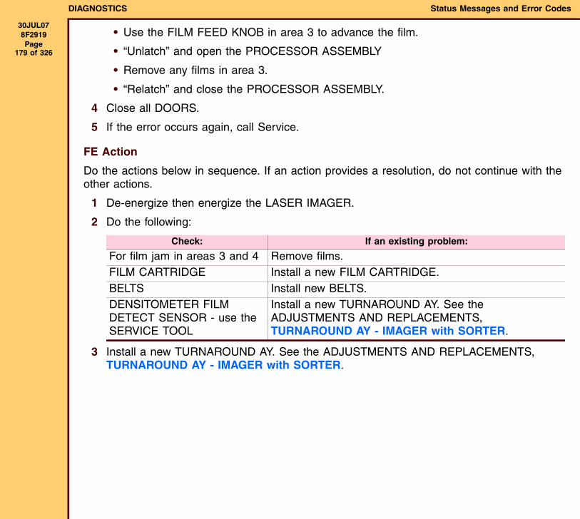
DIAGNOSTICS Status Messages and Error Codes
30JUL078F2919 Page
179 of 326
• Use the FILM FEED KNOB in area 3 to advance the film.
• “Unlatch” and open the PROCESSOR ASSEMBLY
• Remove any films in area 3.
• “Relatch” and close the PROCESSOR ASSEMBLY.
4 Close all DOORS.
5 If the error occurs again, call Service.
FE Action
Do the actions below in sequence. If an action provides a resolution, do not continue with the other actions.
1 De-energize then energize the LASER IMAGER.
2 Do the following:
3 Install a new TURNAROUND AY. See the ADJUSTMENTS AND REPLACEMENTS, TURNAROUND AY - IMAGER with SORTER.
Check: If an existing problem:
For film jam in areas 3 and 4 Remove films.FILM CARTRIDGE Install a new FILM CARTRIDGE.BELTS Install new BELTS.DENSITOMETER FILM DETECT SENSOR - use the SERVICE TOOL
Install a new TURNAROUND AY. See the ADJUSTMENTS AND REPLACEMENTS, TURNAROUND AY - IMAGER with SORTER.
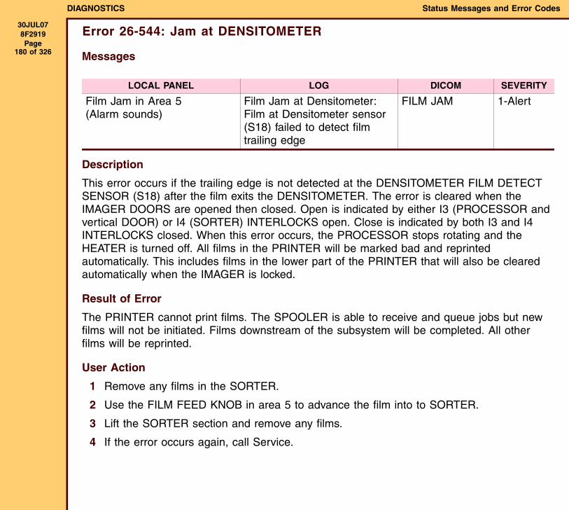
DIAGNOSTICS Status Messages and Error Codes
30JUL078F2919 Page
180 of 326
Error 26-544: Jam at DENSITOMETER
Messages
Description
This error occurs if the trailing edge is not detected at the DENSITOMETER FILM DETECT SENSOR (S18) after the film exits the DENSITOMETER. The error is cleared when the IMAGER DOORS are opened then closed. Open is indicated by either I3 (PROCESSOR and vertical DOOR) or I4 (SORTER) INTERLOCKS open. Close is indicated by both I3 and I4 INTERLOCKS closed. When this error occurs, the PROCESSOR stops rotating and the HEATER is turned off. All films in the PRINTER will be marked bad and reprinted automatically. This includes films in the lower part of the PRINTER that will also be cleared automatically when the IMAGER is locked.
Result of Error
The PRINTER cannot print films. The SPOOLER is able to receive and queue jobs but new films will not be initiated. Films downstream of the subsystem will be completed. All other films will be reprinted.
User Action
1 Remove any films in the SORTER.
2 Use the FILM FEED KNOB in area 5 to advance the film into to SORTER.
3 Lift the SORTER section and remove any films.
4 If the error occurs again, call Service.
LOCAL PANEL LOG DICOM SEVERITY
Film Jam in Area 5(Alarm sounds)
Film Jam at Densitometer: Film at Densitometer sensor (S18) failed to detect film trailing edge
FILM JAM 1-Alert
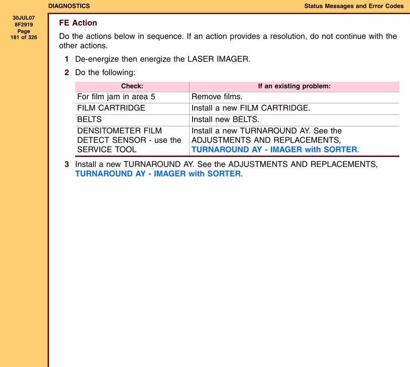
DIAGNOSTICS Status Messages and Error Codes
30JUL078F2919 Page
181 of 326
FE Action
Do the actions below in sequence. If an action provides a resolution, do not continue with the other actions.
1 De-energize then energize the LASER IMAGER.
2 Do the following:
3 Install a new TURNAROUND AY. See the ADJUSTMENTS AND REPLACEMENTS, TURNAROUND AY - IMAGER with SORTER.
Check: If an existing problem:
For film jam in area 5 Remove films.FILM CARTRIDGE Install a new FILM CARTRIDGE.BELTS Install new BELTS.DENSITOMETER FILM DETECT SENSOR - use the SERVICE TOOL
Install a new TURNAROUND AY. See the ADJUSTMENTS AND REPLACEMENTS, TURNAROUND AY - IMAGER with SORTER.
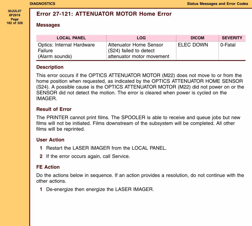
DIAGNOSTICS Status Messages and Error Codes
30JUL078F2919 Page
182 of 326
Error 27-121: ATTENUATOR MOTOR Home Error
Messages
Description
This error occurs if the OPTICS ATTENUATOR MOTOR (M22) does not move to or from the home position when requested, as indicated by the OPTICS ATTENUATOR HOME SENSOR (S24). A possible cause is the OPTICS ATTENUATOR MOTOR (M22) did not power on or the SENSOR did not detect the motion. The error is cleared when power is cycled on the IMAGER.
Result of Error
The PRINTER cannot print films. The SPOOLER is able to receive and queue jobs but new films will not be initiated. Films downstream of the subsystem will be completed. All other films will be reprinted.
User Action
1 Restart the LASER IMAGER from the LOCAL PANEL.
2 If the error occurs again, call Service.
FE Action
Do the actions below in sequence. If an action provides a resolution, do not continue with the other actions.
1 De-energize then energize the LASER IMAGER.
LOCAL PANEL LOG DICOM SEVERITY
Optics: Internal Hardware Failure(Alarm sounds)
Attenuator Home Sensor (S24) failed to detect attenuator motor movement
ELEC DOWN 0-Fatal
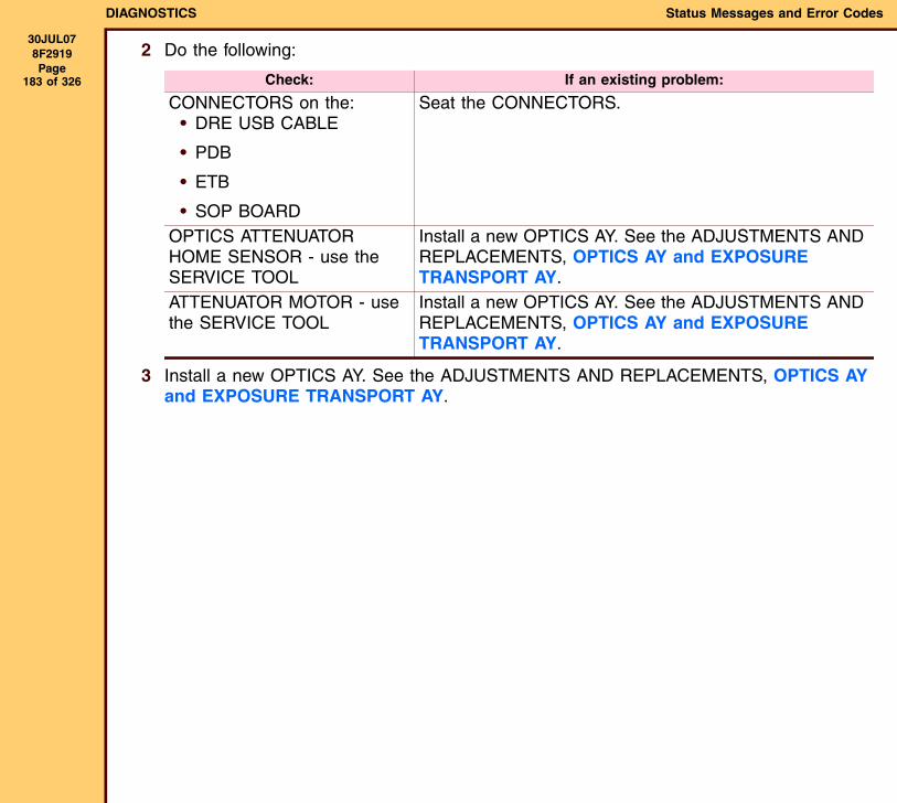
DIAGNOSTICS Status Messages and Error Codes
30JUL078F2919 Page
183 of 326
2 Do the following:
3 Install a new OPTICS AY. See the ADJUSTMENTS AND REPLACEMENTS, OPTICS AY and EXPOSURE TRANSPORT AY.
Check: If an existing problem:
CONNECTORS on the:• DRE USB CABLE
• PDB
• ETB
• SOP BOARD
Seat the CONNECTORS.
OPTICS ATTENUATOR HOME SENSOR - use the SERVICE TOOL
Install a new OPTICS AY. See the ADJUSTMENTS AND REPLACEMENTS, OPTICS AY and EXPOSURE TRANSPORT AY.
ATTENUATOR MOTOR - use the SERVICE TOOL
Install a new OPTICS AY. See the ADJUSTMENTS AND REPLACEMENTS, OPTICS AY and EXPOSURE TRANSPORT AY.
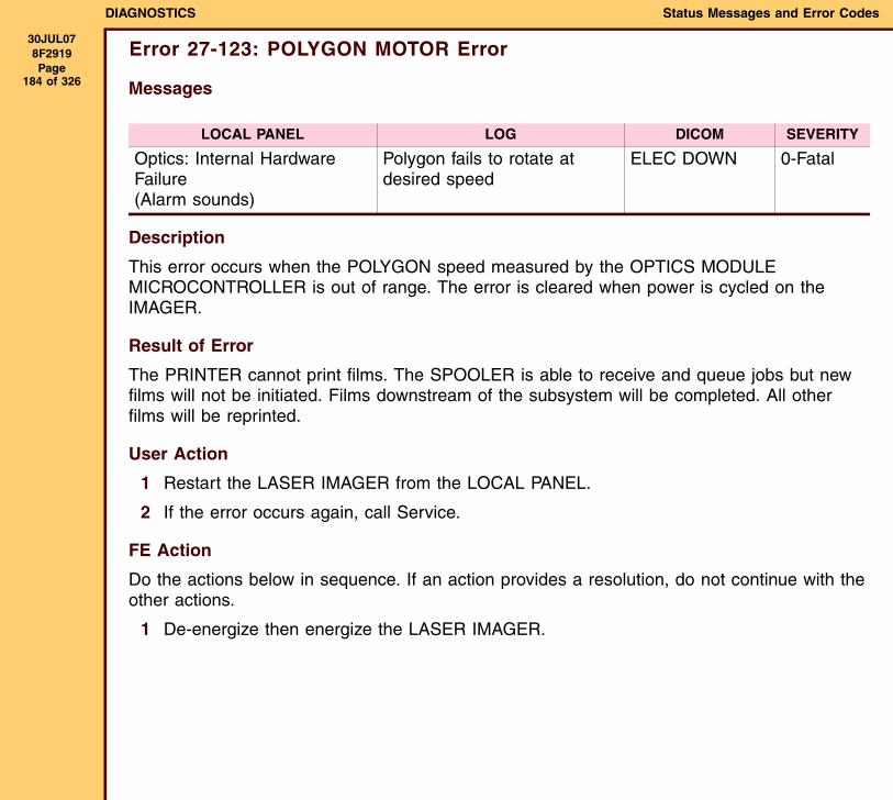
DIAGNOSTICS Status Messages and Error Codes
30JUL078F2919 Page
184 of 326
Error 27-123: POLYGON MOTOR Error
Messages
Description
This error occurs when the POLYGON speed measured by the OPTICS MODULE MICROCONTROLLER is out of range. The error is cleared when power is cycled on the IMAGER.
Result of Error
The PRINTER cannot print films. The SPOOLER is able to receive and queue jobs but new films will not be initiated. Films downstream of the subsystem will be completed. All other films will be reprinted.
User Action
1 Restart the LASER IMAGER from the LOCAL PANEL.
2 If the error occurs again, call Service.
FE Action
Do the actions below in sequence. If an action provides a resolution, do not continue with the other actions.
1 De-energize then energize the LASER IMAGER.
LOCAL PANEL LOG DICOM SEVERITY
Optics: Internal Hardware Failure(Alarm sounds)
Polygon fails to rotate at desired speed
ELEC DOWN 0-Fatal
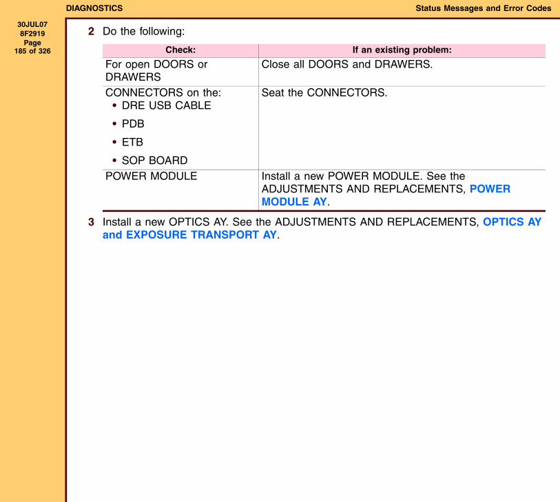
DIAGNOSTICS Status Messages and Error Codes
30JUL078F2919 Page
185 of 326
2 Do the following:
3 Install a new OPTICS AY. See the ADJUSTMENTS AND REPLACEMENTS, OPTICS AY and EXPOSURE TRANSPORT AY.
Check: If an existing problem:
For open DOORS or DRAWERS
Close all DOORS and DRAWERS.
CONNECTORS on the:• DRE USB CABLE
• PDB
• ETB
• SOP BOARD
Seat the CONNECTORS.
POWER MODULE Install a new POWER MODULE. See the ADJUSTMENTS AND REPLACEMENTS, POWER MODULE AY.
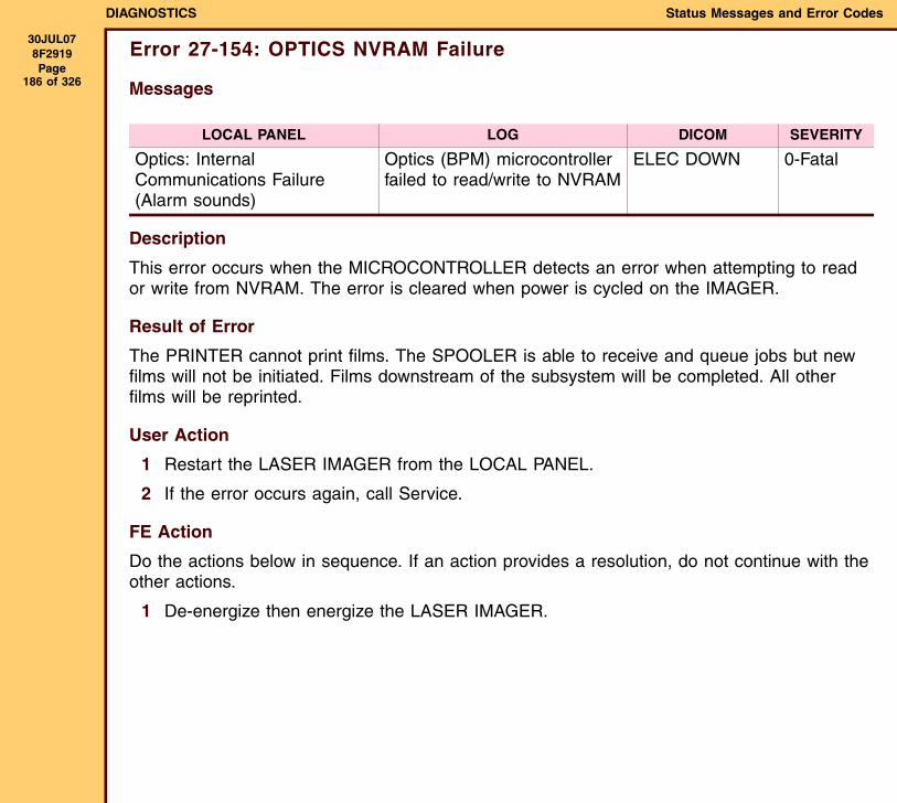
DIAGNOSTICS Status Messages and Error Codes
30JUL078F2919 Page
186 of 326
Error 27-154: OPTICS NVRAM Failure
Messages
Description
This error occurs when the MICROCONTROLLER detects an error when attempting to read or write from NVRAM. The error is cleared when power is cycled on the IMAGER.
Result of Error
The PRINTER cannot print films. The SPOOLER is able to receive and queue jobs but new films will not be initiated. Films downstream of the subsystem will be completed. All other films will be reprinted.
User Action
1 Restart the LASER IMAGER from the LOCAL PANEL.
2 If the error occurs again, call Service.
FE Action
Do the actions below in sequence. If an action provides a resolution, do not continue with the other actions.
1 De-energize then energize the LASER IMAGER.
LOCAL PANEL LOG DICOM SEVERITY
Optics: Internal Communications Failure(Alarm sounds)
Optics (BPM) microcontroller failed to read/write to NVRAM
ELEC DOWN 0-Fatal
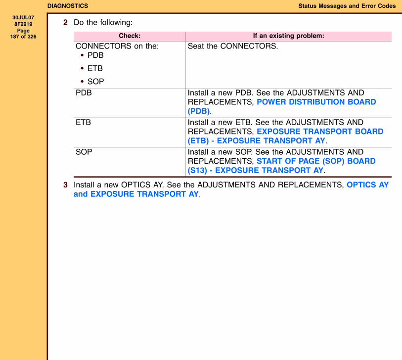
DIAGNOSTICS Status Messages and Error Codes
30JUL078F2919 Page
187 of 326
2 Do the following:
3 Install a new OPTICS AY. See the ADJUSTMENTS AND REPLACEMENTS, OPTICS AY and EXPOSURE TRANSPORT AY.
Check: If an existing problem:
CONNECTORS on the:• PDB
• ETB
• SOP
Seat the CONNECTORS.
PDB Install a new PDB. See the ADJUSTMENTS AND REPLACEMENTS, POWER DISTRIBUTION BOARD (PDB).
ETB Install a new ETB. See the ADJUSTMENTS AND REPLACEMENTS, EXPOSURE TRANSPORT BOARD (ETB) - EXPOSURE TRANSPORT AY.
SOP Install a new SOP. See the ADJUSTMENTS AND REPLACEMENTS, START OF PAGE (SOP) BOARD (S13) - EXPOSURE TRANSPORT AY.
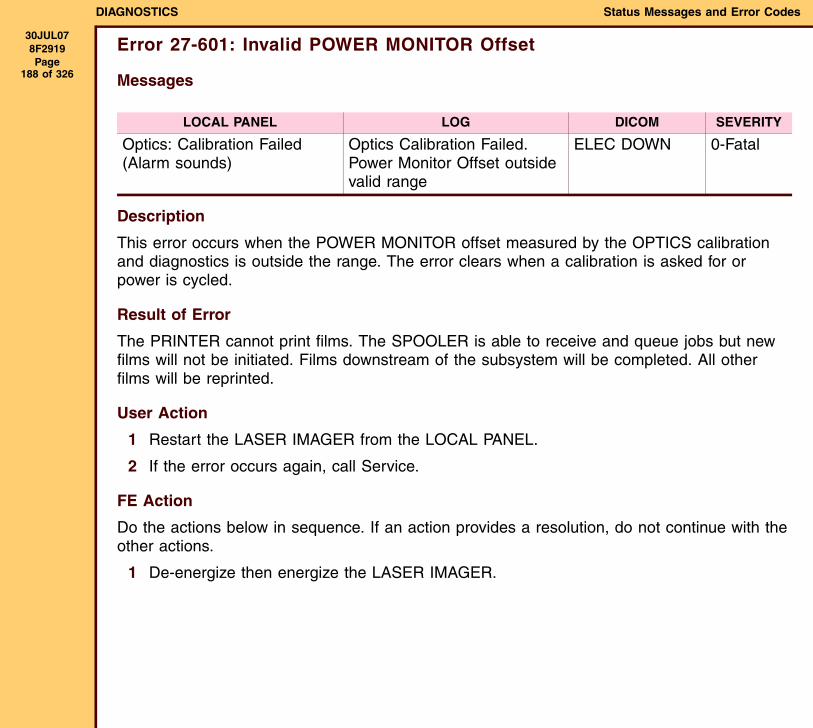
DIAGNOSTICS Status Messages and Error Codes
30JUL078F2919 Page
188 of 326
Error 27-601: Invalid POWER MONITOR Offset
Messages
Description
This error occurs when the POWER MONITOR offset measured by the OPTICS calibration and diagnostics is outside the range. The error clears when a calibration is asked for or power is cycled.
Result of Error
The PRINTER cannot print films. The SPOOLER is able to receive and queue jobs but new films will not be initiated. Films downstream of the subsystem will be completed. All other films will be reprinted.
User Action
1 Restart the LASER IMAGER from the LOCAL PANEL.
2 If the error occurs again, call Service.
FE Action
Do the actions below in sequence. If an action provides a resolution, do not continue with the other actions.
1 De-energize then energize the LASER IMAGER.
LOCAL PANEL LOG DICOM SEVERITY
Optics: Calibration Failed(Alarm sounds)
Optics Calibration Failed. Power Monitor Offset outside valid range
ELEC DOWN 0-Fatal
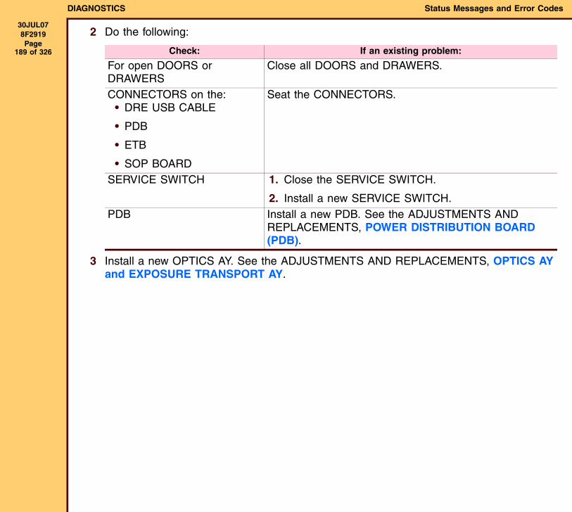
DIAGNOSTICS Status Messages and Error Codes
30JUL078F2919 Page
189 of 326
2 Do the following:
3 Install a new OPTICS AY. See the ADJUSTMENTS AND REPLACEMENTS, OPTICS AY and EXPOSURE TRANSPORT AY.
Check: If an existing problem:
For open DOORS or DRAWERS
Close all DOORS and DRAWERS.
CONNECTORS on the:• DRE USB CABLE
• PDB
• ETB
• SOP BOARD
Seat the CONNECTORS.
SERVICE SWITCH 1. Close the SERVICE SWITCH.
2. Install a new SERVICE SWITCH.PDB Install a new PDB. See the ADJUSTMENTS AND
REPLACEMENTS, POWER DISTRIBUTION BOARD (PDB).
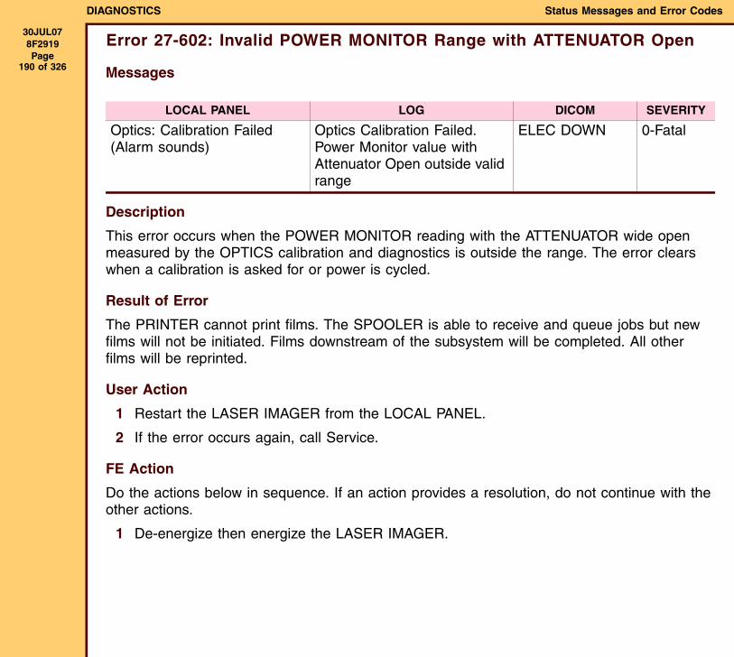
DIAGNOSTICS Status Messages and Error Codes
30JUL078F2919 Page
190 of 326
Error 27-602: Invalid POWER MONITOR Range with ATTENUATOR Open
Messages
Description
This error occurs when the POWER MONITOR reading with the ATTENUATOR wide open measured by the OPTICS calibration and diagnostics is outside the range. The error clears when a calibration is asked for or power is cycled.
Result of Error
The PRINTER cannot print films. The SPOOLER is able to receive and queue jobs but new films will not be initiated. Films downstream of the subsystem will be completed. All other films will be reprinted.
User Action
1 Restart the LASER IMAGER from the LOCAL PANEL.
2 If the error occurs again, call Service.
FE Action
Do the actions below in sequence. If an action provides a resolution, do not continue with the other actions.
1 De-energize then energize the LASER IMAGER.
LOCAL PANEL LOG DICOM SEVERITY
Optics: Calibration Failed(Alarm sounds)
Optics Calibration Failed. Power Monitor value with Attenuator Open outside valid range
ELEC DOWN 0-Fatal
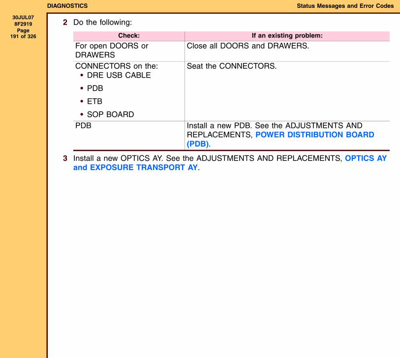
DIAGNOSTICS Status Messages and Error Codes
30JUL078F2919 Page
191 of 326
2 Do the following:
3 Install a new OPTICS AY. See the ADJUSTMENTS AND REPLACEMENTS, OPTICS AY and EXPOSURE TRANSPORT AY.
Check: If an existing problem:
For open DOORS or DRAWERS
Close all DOORS and DRAWERS.
CONNECTORS on the:• DRE USB CABLE
• PDB
• ETB
• SOP BOARD
Seat the CONNECTORS.
PDB Install a new PDB. See the ADJUSTMENTS AND REPLACEMENTS, POWER DISTRIBUTION BOARD (PDB).
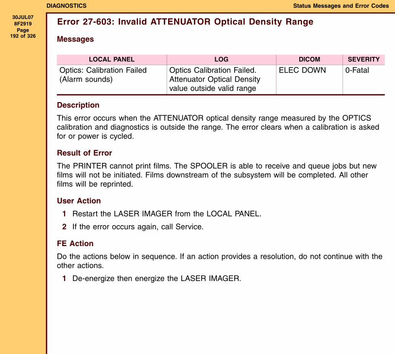
DIAGNOSTICS Status Messages and Error Codes
30JUL078F2919 Page
192 of 326
Error 27-603: Invalid ATTENUATOR Optical Density Range
Messages
Description
This error occurs when the ATTENUATOR optical density range measured by the OPTICS calibration and diagnostics is outside the range. The error clears when a calibration is asked for or power is cycled.
Result of Error
The PRINTER cannot print films. The SPOOLER is able to receive and queue jobs but new films will not be initiated. Films downstream of the subsystem will be completed. All other films will be reprinted.
User Action
1 Restart the LASER IMAGER from the LOCAL PANEL.
2 If the error occurs again, call Service.
FE Action
Do the actions below in sequence. If an action provides a resolution, do not continue with the other actions.
1 De-energize then energize the LASER IMAGER.
LOCAL PANEL LOG DICOM SEVERITY
Optics: Calibration Failed(Alarm sounds)
Optics Calibration Failed. Attenuator Optical Density value outside valid range
ELEC DOWN 0-Fatal

DIAGNOSTICS Status Messages and Error Codes
30JUL078F2919 Page
193 of 326
2 Do the following:
3 Install a new OPTICS AY. See the ADJUSTMENTS AND REPLACEMENTS, OPTICS AY and EXPOSURE TRANSPORT AY.
Check: If an existing problem:
For open DOORS or DRAWERS
Close all DOORS and DRAWERS.
CONNECTORS on the:• DRE USB CABLE
• PDB
• ETB
• SOP BOARD
Seat the CONNECTORS.
PDB Install a new PDB. See the ADJUSTMENTS AND REPLACEMENTS, POWER DISTRIBUTION BOARD (PDB).
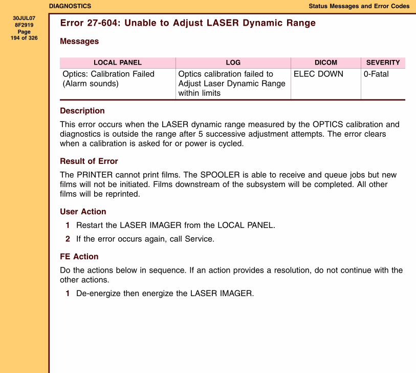
DIAGNOSTICS Status Messages and Error Codes
30JUL078F2919 Page
194 of 326
Error 27-604: Unable to Adjust LASER Dynamic Range
Messages
Description
This error occurs when the LASER dynamic range measured by the OPTICS calibration and diagnostics is outside the range after 5 successive adjustment attempts. The error clears when a calibration is asked for or power is cycled.
Result of Error
The PRINTER cannot print films. The SPOOLER is able to receive and queue jobs but new films will not be initiated. Films downstream of the subsystem will be completed. All other films will be reprinted.
User Action
1 Restart the LASER IMAGER from the LOCAL PANEL.
2 If the error occurs again, call Service.
FE Action
Do the actions below in sequence. If an action provides a resolution, do not continue with the other actions.
1 De-energize then energize the LASER IMAGER.
LOCAL PANEL LOG DICOM SEVERITY
Optics: Calibration Failed(Alarm sounds)
Optics calibration failed to Adjust Laser Dynamic Range within limits
ELEC DOWN 0-Fatal

DIAGNOSTICS Status Messages and Error Codes
30JUL078F2919 Page
195 of 326
2 Do the following:
3 Install a new OPTICS AY. See the ADJUSTMENTS AND REPLACEMENTS, OPTICS AY and EXPOSURE TRANSPORT AY.
Check: If an existing problem:
For open DOORS or DRAWERS
Close all DOORS and DRAWERS.
CONNECTORS on the:• DRE USB CABLE
• PDB
• ETB
• SOP BOARD
Seat the CONNECTORS.
PDB Install a new PDB. See the ADJUSTMENTS AND REPLACEMENTS, POWER DISTRIBUTION BOARD (PDB).
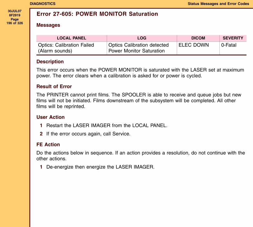
DIAGNOSTICS Status Messages and Error Codes
30JUL078F2919 Page
196 of 326
Error 27-605: POWER MONITOR Saturation
Messages
Description
This error occurs when the POWER MONITOR is saturated with the LASER set at maximum power. The error clears when a calibration is asked for or power is cycled.
Result of Error
The PRINTER cannot print films. The SPOOLER is able to receive and queue jobs but new films will not be initiated. Films downstream of the subsystem will be completed. All other films will be reprinted.
User Action
1 Restart the LASER IMAGER from the LOCAL PANEL.
2 If the error occurs again, call Service.
FE Action
Do the actions below in sequence. If an action provides a resolution, do not continue with the other actions.
1 De-energize then energize the LASER IMAGER.
LOCAL PANEL LOG DICOM SEVERITY
Optics: Calibration Failed(Alarm sounds)
Optics Calibration detected Power Monitor Saturation
ELEC DOWN 0-Fatal

DIAGNOSTICS Status Messages and Error Codes
30JUL078F2919 Page
197 of 326
2 Do the following:
3 Install a new OPTICS AY. See the ADJUSTMENTS AND REPLACEMENTS, OPTICS AY and EXPOSURE TRANSPORT AY.
Check: If an existing problem:
For open DOORS or DRAWERS
Close all DOORS and DRAWERS.
CONNECTORS on the:• DRE USB CABLE
• PDB
• ETB
• SOP BOARD
Seat the CONNECTORS.
PDB Install a new PDB. See the ADJUSTMENTS AND REPLACEMENTS, POWER DISTRIBUTION BOARD (PDB).
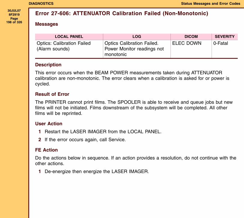
DIAGNOSTICS Status Messages and Error Codes
30JUL078F2919 Page
198 of 326
Error 27-606: ATTENUATOR Calibration Failed (Non-Monotonic)
Messages
Description
This error occurs when the BEAM POWER measurements taken during ATTENUATOR calibration are non-monotonic. The error clears when a calibration is asked for or power is cycled.
Result of Error
The PRINTER cannot print films. The SPOOLER is able to receive and queue jobs but new films will not be initiated. Films downstream of the subsystem will be completed. All other films will be reprinted.
User Action
1 Restart the LASER IMAGER from the LOCAL PANEL.
2 If the error occurs again, call Service.
FE Action
Do the actions below in sequence. If an action provides a resolution, do not continue with the other actions.
1 De-energize then energize the LASER IMAGER.
LOCAL PANEL LOG DICOM SEVERITY
Optics: Calibration Failed(Alarm sounds)
Optics Calibration Failed. Power Monitor readings not monotonic
ELEC DOWN 0-Fatal

DIAGNOSTICS Status Messages and Error Codes
30JUL078F2919 Page
199 of 326
2 Do the following:
3 Install a new OPTICS AY. See the ADJUSTMENTS AND REPLACEMENTS, OPTICS AY and EXPOSURE TRANSPORT AY.
Check: If an existing problem:
For open DOORS or DRAWERS
Close all DOORS and DRAWERS.
CONNECTORS on the:• DRE USB CABLE
• PDB
• ETB
• SOP BOARD
Seat the CONNECTORS.
PDB Install a new PDB. See the ADJUSTMENTS AND REPLACEMENTS, POWER DISTRIBUTION BOARD (PDB).
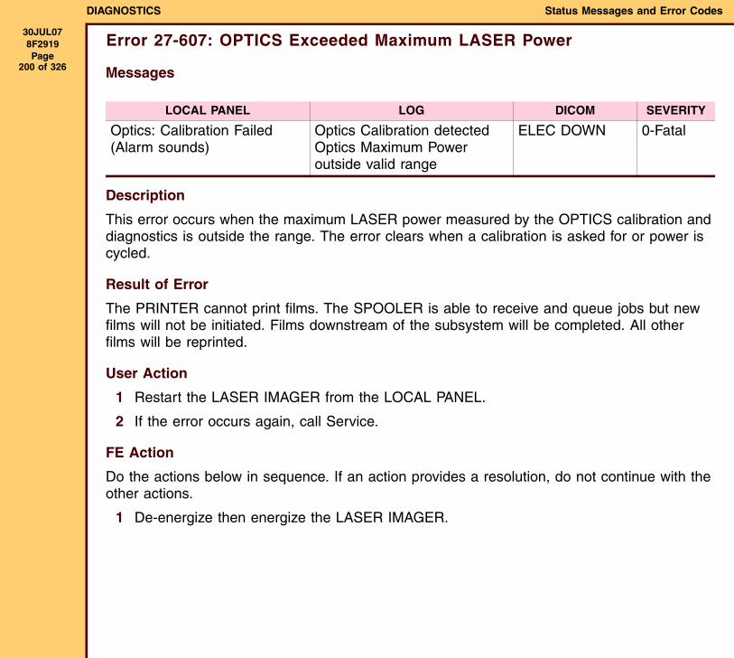
DIAGNOSTICS Status Messages and Error Codes
30JUL078F2919 Page
200 of 326
Error 27-607: OPTICS Exceeded Maximum LASER Power
Messages
Description
This error occurs when the maximum LASER power measured by the OPTICS calibration and diagnostics is outside the range. The error clears when a calibration is asked for or power is cycled.
Result of Error
The PRINTER cannot print films. The SPOOLER is able to receive and queue jobs but new films will not be initiated. Films downstream of the subsystem will be completed. All other films will be reprinted.
User Action
1 Restart the LASER IMAGER from the LOCAL PANEL.
2 If the error occurs again, call Service.
FE Action
Do the actions below in sequence. If an action provides a resolution, do not continue with the other actions.
1 De-energize then energize the LASER IMAGER.
LOCAL PANEL LOG DICOM SEVERITY
Optics: Calibration Failed(Alarm sounds)
Optics Calibration detected Optics Maximum Power outside valid range
ELEC DOWN 0-Fatal

DIAGNOSTICS Status Messages and Error Codes
30JUL078F2919 Page
201 of 326
2 Do the following:
3 Install a new OPTICS AY. See the ADJUSTMENTS AND REPLACEMENTS, OPTICS AY and EXPOSURE TRANSPORT AY.
Check: If an existing problem:
For open DOORS or DRAWERS
Close all DOORS and DRAWERS.
CONNECTORS on the:• DRE USB CABLE
• PDB
• ETB
• SOP BOARD
Seat the CONNECTORS.
PDB Install a new PDB. See the ADJUSTMENTS AND REPLACEMENTS, POWER DISTRIBUTION BOARD (PDB).
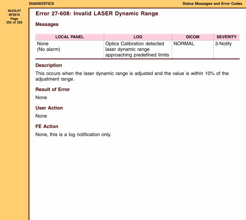
DIAGNOSTICS Status Messages and Error Codes
30JUL078F2919 Page
202 of 326
Error 27-608: Invalid LASER Dynamic Range
Messages
Description
This occurs when the laser dynamic range is adjusted and the value is within 10% of the adjustment range.
Result of Error
None
User Action
None
FE Action
None, this is a log notification only.
LOCAL PANEL LOG DICOM SEVERITY
None(No alarm)
Optics Calibration detected laser dynamic range approaching predefined limits
NORMAL 3-Notify
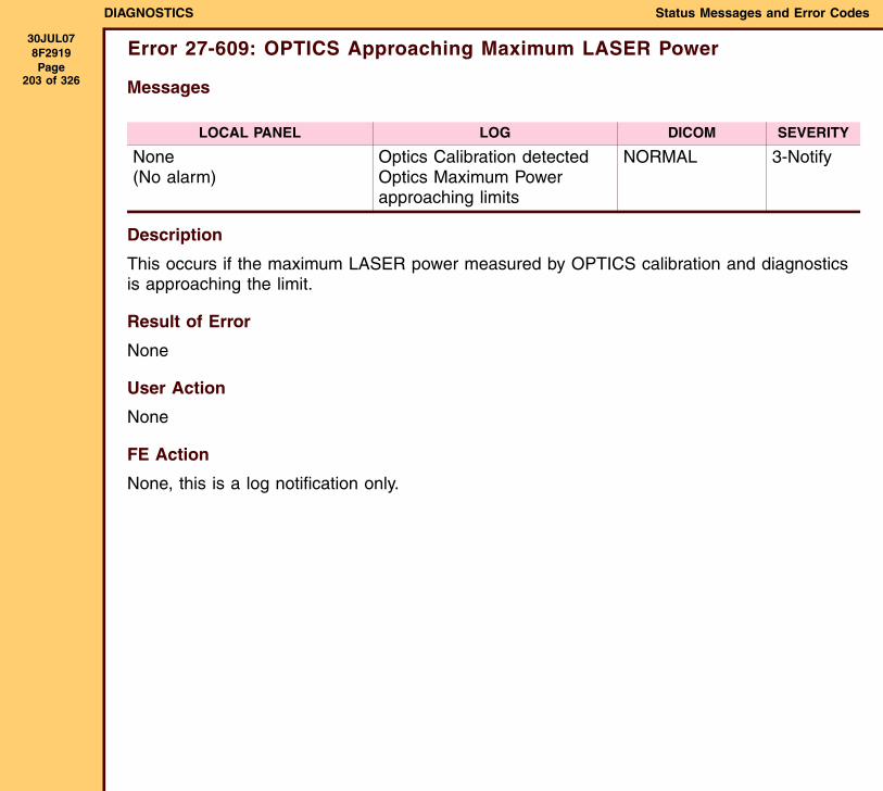
DIAGNOSTICS Status Messages and Error Codes
30JUL078F2919 Page
203 of 326
Error 27-609: OPTICS Approaching Maximum LASER Power
Messages
Description
This occurs if the maximum LASER power measured by OPTICS calibration and diagnostics is approaching the limit.
Result of Error
None
User Action
None
FE Action
None, this is a log notification only.
LOCAL PANEL LOG DICOM SEVERITY
None(No alarm)
Optics Calibration detected Optics Maximum Power approaching limits
NORMAL 3-Notify
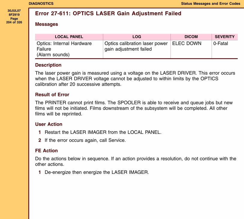
DIAGNOSTICS Status Messages and Error Codes
30JUL078F2919 Page
204 of 326
Error 27-611: OPTICS LASER Gain Adjustment Failed
Messages
Description
The laser power gain is measured using a voltage on the LASER DRIVER. This error occurs when the LASER DRIVER voltage cannot be adjusted to within limits by the OPTICS calibration after 20 successive attempts.
Result of Error
The PRINTER cannot print films. The SPOOLER is able to receive and queue jobs but new films will not be initiated. Films downstream of the subsystem will be completed. All other films will be reprinted.
User Action
1 Restart the LASER IMAGER from the LOCAL PANEL.
2 If the error occurs again, call Service.
FE Action
Do the actions below in sequence. If an action provides a resolution, do not continue with the other actions.
1 De-energize then energize the LASER IMAGER.
LOCAL PANEL LOG DICOM SEVERITY
Optics: Internal Hardware Failure(Alarm sounds)
Optics calibration laser power gain adjustment failed
ELEC DOWN 0-Fatal

DIAGNOSTICS Status Messages and Error Codes
30JUL078F2919 Page
205 of 326
2 Do the following:
3 Install a new OPTICS AY. See the ADJUSTMENTS AND REPLACEMENTS, OPTICS AY and EXPOSURE TRANSPORT AY.
Check: If an existing problem:
For open DOORS or DRAWERS
Close all DOORS and DRAWERS.
CONNECTORS on the:• DRE USB CABLE
• PDB
• ETB
• SOP BOARD
Seat the CONNECTORS.
PDB Install a new PDB. See the ADJUSTMENTS AND REPLACEMENTS, POWER DISTRIBUTION BOARD (PDB).
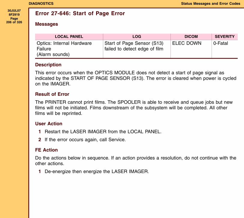
DIAGNOSTICS Status Messages and Error Codes
30JUL078F2919 Page
206 of 326
Error 27-646: Start of Page Error
Messages
Description
This error occurs when the OPTICS MODULE does not detect a start of page signal as indicated by the START OF PAGE SENSOR (S13). The error is cleared when power is cycled on the IMAGER.
Result of Error
The PRINTER cannot print films. The SPOOLER is able to receive and queue jobs but new films will not be initiated. Films downstream of the subsystem will be completed. All other films will be reprinted.
User Action
1 Restart the LASER IMAGER from the LOCAL PANEL.
2 If the error occurs again, call Service.
FE Action
Do the actions below in sequence. If an action provides a resolution, do not continue with the other actions.
1 De-energize then energize the LASER IMAGER.
LOCAL PANEL LOG DICOM SEVERITY
Optics: Internal Hardware Failure (Alarm sounds)
Start of Page Sensor (S13) failed to detect edge of film
ELEC DOWN 0-Fatal
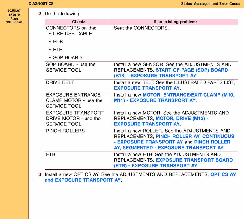
DIAGNOSTICS Status Messages and Error Codes
30JUL078F2919 Page
207 of 326
2 Do the following:
3 Install a new OPTICS AY. See the ADJUSTMENTS AND REPLACEMENTS, OPTICS AY and EXPOSURE TRANSPORT AY.
Check: If an existing problem:
CONNECTORS on the:• DRE USB CABLE
• PDB
• ETB
• SOP BOARD
Seat the CONNECTORS.
SOP BOARD - use the SERVICE TOOL
Install a new SENSOR. See the ADJUSTMENTS AND REPLACEMENTS, START OF PAGE (SOP) BOARD (S13) - EXPOSURE TRANSPORT AY.
DRIVE BELT Install a new BELT. See the ILLUSTRATED PARTS LIST, EXPOSURE TRANSPORT AY.
EXPOSURE ENTRANCE CLAMP MOTOR - use the SERVICE TOOL
Install a new MOTOR, ENTRANCE/EXIT CLAMP (M10, M11) - EXPOSURE TRANSPORT AY.
EXPOSURE TRANSPORT DRIVE MOTOR - use the SERVICE TOOL
Install a new MOTOR. See the ADJUSTMENTS AND REPLACEMENTS, MOTOR, DRIVE (M12) - EXPOSURE TRANSPORT AY.
PINCH ROLLERS Install a new ROLLER. See the ADJUSTMENTS AND REPLACEMENTS, PINCH ROLLER AY, CONTINUOUS - EXPOSURE TRANSPORT AY and PINCH ROLLER AY, SEGMENTED - EXPOSURE TRANSPORT AY.
ETB Install a new ETB. See the ADJUSTMENTS AND REPLACEMENTS, EXPOSURE TRANSPORT BOARD (ETB) - EXPOSURE TRANSPORT AY.
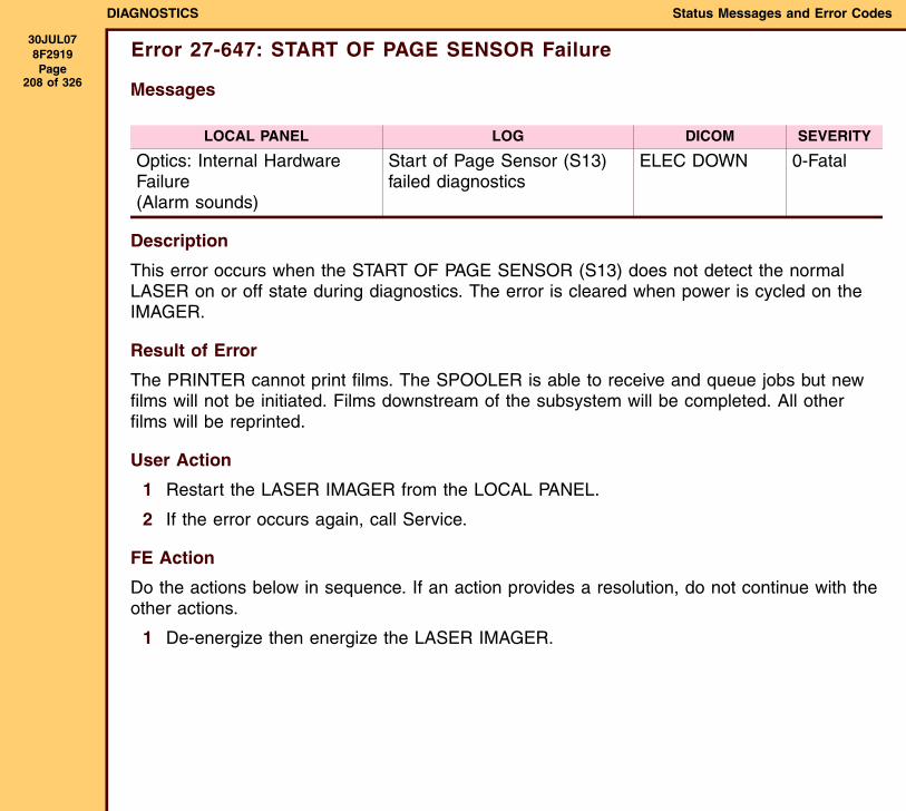
DIAGNOSTICS Status Messages and Error Codes
30JUL078F2919 Page
208 of 326
Error 27-647: START OF PAGE SENSOR Failure
Messages
Description
This error occurs when the START OF PAGE SENSOR (S13) does not detect the normal LASER on or off state during diagnostics. The error is cleared when power is cycled on the IMAGER.
Result of Error
The PRINTER cannot print films. The SPOOLER is able to receive and queue jobs but new films will not be initiated. Films downstream of the subsystem will be completed. All other films will be reprinted.
User Action
1 Restart the LASER IMAGER from the LOCAL PANEL.
2 If the error occurs again, call Service.
FE Action
Do the actions below in sequence. If an action provides a resolution, do not continue with the other actions.
1 De-energize then energize the LASER IMAGER.
LOCAL PANEL LOG DICOM SEVERITY
Optics: Internal Hardware Failure (Alarm sounds)
Start of Page Sensor (S13) failed diagnostics
ELEC DOWN 0-Fatal
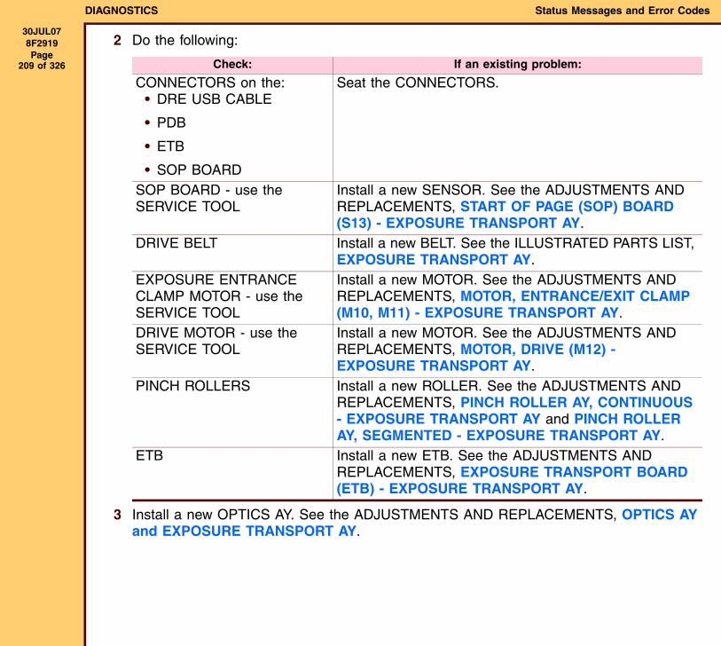
DIAGNOSTICS Status Messages and Error Codes
30JUL078F2919 Page
209 of 326
2 Do the following:
3 Install a new OPTICS AY. See the ADJUSTMENTS AND REPLACEMENTS, OPTICS AY and EXPOSURE TRANSPORT AY.
Check: If an existing problem:
CONNECTORS on the:• DRE USB CABLE
• PDB
• ETB
• SOP BOARD
Seat the CONNECTORS.
SOP BOARD - use the SERVICE TOOL
Install a new SENSOR. See the ADJUSTMENTS AND REPLACEMENTS, START OF PAGE (SOP) BOARD (S13) - EXPOSURE TRANSPORT AY.
DRIVE BELT Install a new BELT. See the ILLUSTRATED PARTS LIST, EXPOSURE TRANSPORT AY.
EXPOSURE ENTRANCE CLAMP MOTOR - use the SERVICE TOOL
Install a new MOTOR. See the ADJUSTMENTS AND REPLACEMENTS, MOTOR, ENTRANCE/EXIT CLAMP (M10, M11) - EXPOSURE TRANSPORT AY.
DRIVE MOTOR - use the SERVICE TOOL
Install a new MOTOR. See the ADJUSTMENTS AND REPLACEMENTS, MOTOR, DRIVE (M12) - EXPOSURE TRANSPORT AY.
PINCH ROLLERS Install a new ROLLER. See the ADJUSTMENTS AND REPLACEMENTS, PINCH ROLLER AY, CONTINUOUS - EXPOSURE TRANSPORT AY and PINCH ROLLER AY, SEGMENTED - EXPOSURE TRANSPORT AY.
ETB Install a new ETB. See the ADJUSTMENTS AND REPLACEMENTS, EXPOSURE TRANSPORT BOARD (ETB) - EXPOSURE TRANSPORT AY.
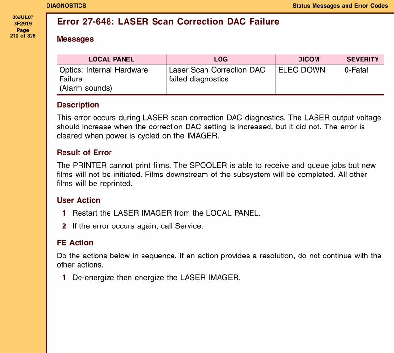
DIAGNOSTICS Status Messages and Error Codes
30JUL078F2919 Page
210 of 326
Error 27-648: LASER Scan Correction DAC Failure
Messages
Description
This error occurs during LASER scan correction DAC diagnostics. The LASER output voltage should increase when the correction DAC setting is increased, but it did not. The error is cleared when power is cycled on the IMAGER.
Result of Error
The PRINTER cannot print films. The SPOOLER is able to receive and queue jobs but new films will not be initiated. Films downstream of the subsystem will be completed. All other films will be reprinted.
User Action
1 Restart the LASER IMAGER from the LOCAL PANEL.
2 If the error occurs again, call Service.
FE Action
Do the actions below in sequence. If an action provides a resolution, do not continue with the other actions.
1 De-energize then energize the LASER IMAGER.
LOCAL PANEL LOG DICOM SEVERITY
Optics: Internal Hardware Failure (Alarm sounds)
Laser Scan Correction DAC failed diagnostics
ELEC DOWN 0-Fatal
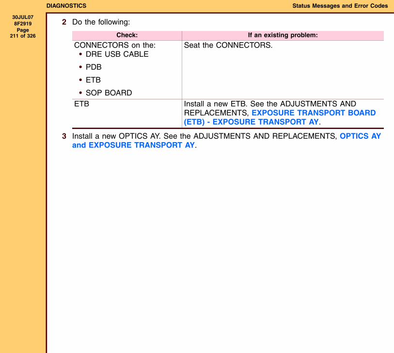
DIAGNOSTICS Status Messages and Error Codes
30JUL078F2919 Page
211 of 326
2 Do the following:
3 Install a new OPTICS AY. See the ADJUSTMENTS AND REPLACEMENTS, OPTICS AY and EXPOSURE TRANSPORT AY.
Check: If an existing problem:
CONNECTORS on the:• DRE USB CABLE
• PDB
• ETB
• SOP BOARD
Seat the CONNECTORS.
ETB Install a new ETB. See the ADJUSTMENTS AND REPLACEMENTS, EXPOSURE TRANSPORT BOARD (ETB) - EXPOSURE TRANSPORT AY.
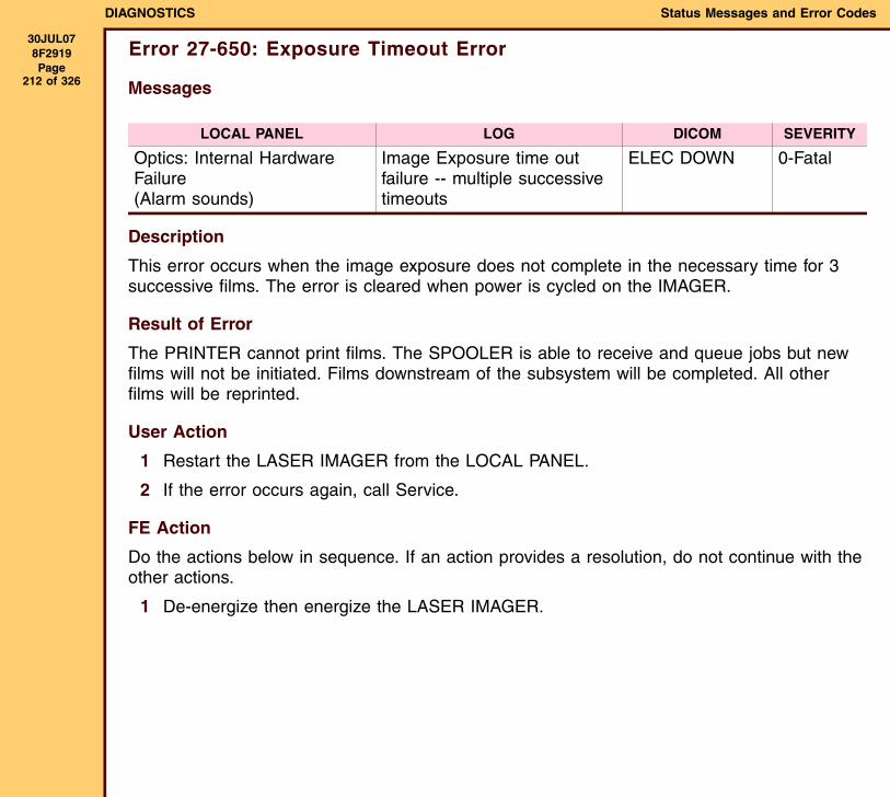
DIAGNOSTICS Status Messages and Error Codes
30JUL078F2919 Page
212 of 326
Error 27-650: Exposure Timeout Error
Messages
Description
This error occurs when the image exposure does not complete in the necessary time for 3 successive films. The error is cleared when power is cycled on the IMAGER.
Result of Error
The PRINTER cannot print films. The SPOOLER is able to receive and queue jobs but new films will not be initiated. Films downstream of the subsystem will be completed. All other films will be reprinted.
User Action
1 Restart the LASER IMAGER from the LOCAL PANEL.
2 If the error occurs again, call Service.
FE Action
Do the actions below in sequence. If an action provides a resolution, do not continue with the other actions.
1 De-energize then energize the LASER IMAGER.
LOCAL PANEL LOG DICOM SEVERITY
Optics: Internal Hardware Failure(Alarm sounds)
Image Exposure time out failure -- multiple successive timeouts
ELEC DOWN 0-Fatal

DIAGNOSTICS Status Messages and Error Codes
30JUL078F2919 Page
213 of 326
2 Do the following:
3 Install a new OPTICS AY. See the ADJUSTMENTS AND REPLACEMENTS, OPTICS AY and EXPOSURE TRANSPORT AY.
Check: If an existing problem:
CONNECTORS on the:• DRE USB CABLE
• PDB
• ETB
• SOP BOARD
Seat the CONNECTORS.
ETB Install a new ETB. See the ADJUSTMENTS AND REPLACEMENTS, EXPOSURE TRANSPORT BOARD (ETB) - EXPOSURE TRANSPORT AY.
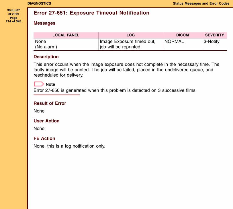
DIAGNOSTICS Status Messages and Error Codes
30JUL078F2919 Page
214 of 326
Error 27-651: Exposure Timeout Notification
Messages
Description
This error occurs when the image exposure does not complete in the necessary time. The faulty image will be printed. The job will be failed, placed in the undelivered queue, and rescheduled for delivery.
NoteError 27-650 is generated when this problem is detected on 3 successive films.
Result of Error
None
User Action
None
FE Action
None, this is a log notification only.
LOCAL PANEL LOG DICOM SEVERITY
None(No alarm)
Image Exposure timed out, job will be reprinted
NORMAL 3-Notify
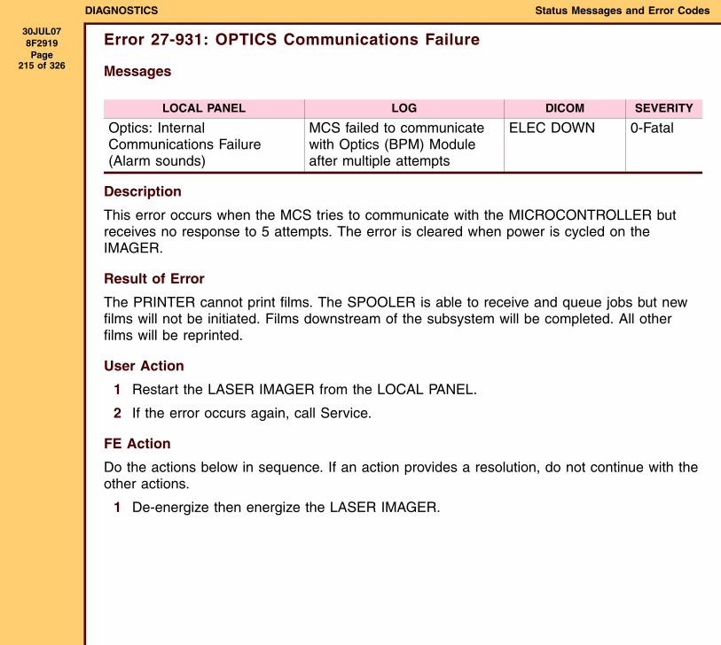
DIAGNOSTICS Status Messages and Error Codes
30JUL078F2919 Page
215 of 326
Error 27-931: OPTICS Communications Failure
Messages
Description
This error occurs when the MCS tries to communicate with the MICROCONTROLLER but receives no response to 5 attempts. The error is cleared when power is cycled on the IMAGER.
Result of Error
The PRINTER cannot print films. The SPOOLER is able to receive and queue jobs but new films will not be initiated. Films downstream of the subsystem will be completed. All other films will be reprinted.
User Action
1 Restart the LASER IMAGER from the LOCAL PANEL.
2 If the error occurs again, call Service.
FE Action
Do the actions below in sequence. If an action provides a resolution, do not continue with the other actions.
1 De-energize then energize the LASER IMAGER.
LOCAL PANEL LOG DICOM SEVERITY
Optics: Internal Communications Failure(Alarm sounds)
MCS failed to communicate with Optics (BPM) Module after multiple attempts
ELEC DOWN 0-Fatal
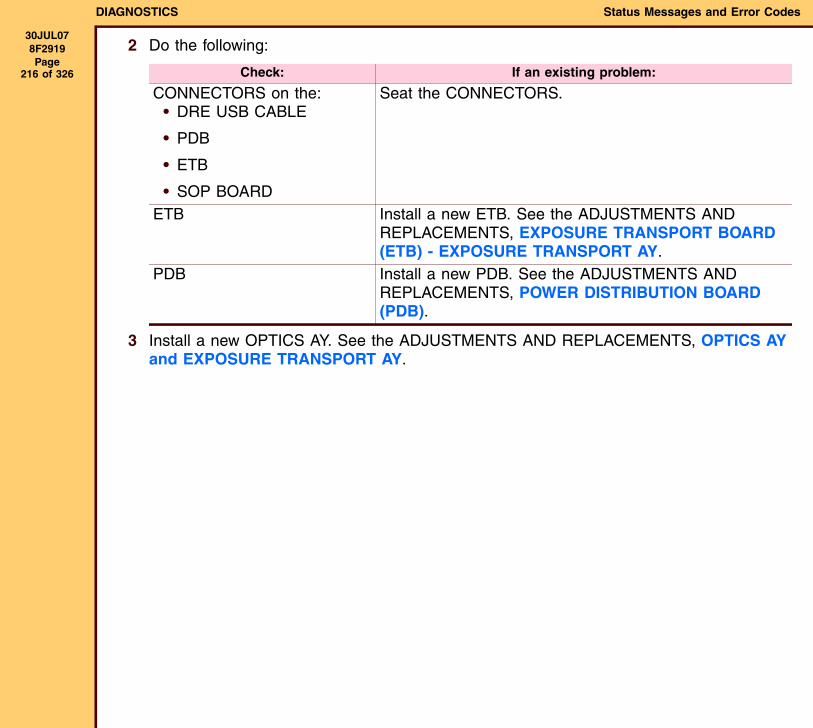
DIAGNOSTICS Status Messages and Error Codes
30JUL078F2919 Page
216 of 326
2 Do the following:
3 Install a new OPTICS AY. See the ADJUSTMENTS AND REPLACEMENTS, OPTICS AY and EXPOSURE TRANSPORT AY.
Check: If an existing problem:
CONNECTORS on the:• DRE USB CABLE
• PDB
• ETB
• SOP BOARD
Seat the CONNECTORS.
ETB Install a new ETB. See the ADJUSTMENTS AND REPLACEMENTS, EXPOSURE TRANSPORT BOARD (ETB) - EXPOSURE TRANSPORT AY.
PDB Install a new PDB. See the ADJUSTMENTS AND REPLACEMENTS, POWER DISTRIBUTION BOARD (PDB).
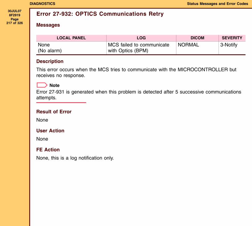
DIAGNOSTICS Status Messages and Error Codes
30JUL078F2919 Page
217 of 326
Error 27-932: OPTICS Communications Retry
Messages
Description
This error occurs when the MCS tries to communicate with the MICROCONTROLLER but receives no response.
NoteError 27-931 is generated when this problem is detected after 5 successive communications attempts.
Result of Error
None
User Action
None
FE Action
None, this is a log notification only.
LOCAL PANEL LOG DICOM SEVERITY
None(No alarm)
MCS failed to communicate with Optics (BPM)
NORMAL 3-Notify

DIAGNOSTICS Status Messages and Error Codes
30JUL078F2919 Page
218 of 326
Error 28-154: PROCESSOR NVRAM Failure
Messages
Description
This error occurs when the MICROCONTROLLER detect an error when attempting to read or write from NVRAM. The error is cleared when power is cycled on the IMAGER.
Result of Error
The PRINTER cannot print films. The SPOOLER is able to receive and queue jobs but new films will not be initiated. Films downstream of the subsystem will be completed. All other films will be reprinted.
User Action
1 Restart the LASER IMAGER from the LOCAL PANEL.
2 If the error occurs again, call Service.
FE Action
Do the actions below in sequence. If an action provides a resolution, do not continue with the other actions.
1 De-energize then energize the LASER IMAGER.
LOCAL PANEL LOG DICOM SEVERITY
Processor: Internal Communications Failure (A beep occurs)
Processor microcontroller failed to read/write to NVRAM
ELEC DOWN 0-Fatal
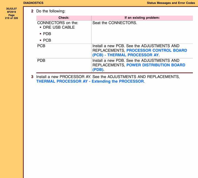
DIAGNOSTICS Status Messages and Error Codes
30JUL078F2919 Page
219 of 326
2 Do the following:
3 Install a new PROCESSOR AY. See the ADJUSTMENTS AND REPLACEMENTS, THERMAL PROCESSOR AY - Extending the PROCESSOR.
Check: If an existing problem:
CONNECTORS on the:• DRE USB CABLE
• PDB
• PCB
Seat the CONNECTORS.
PCB Install a new PCB. See the ADJUSTMENTS AND REPLACEMENTS, PROCESSOR CONTROL BOARD (PCB) - THERMAL PROCESSOR AY.
PDB Install a new PDB. See the ADJUSTMENTS AND REPLACEMENTS, POWER DISTRIBUTION BOARD (PDB).
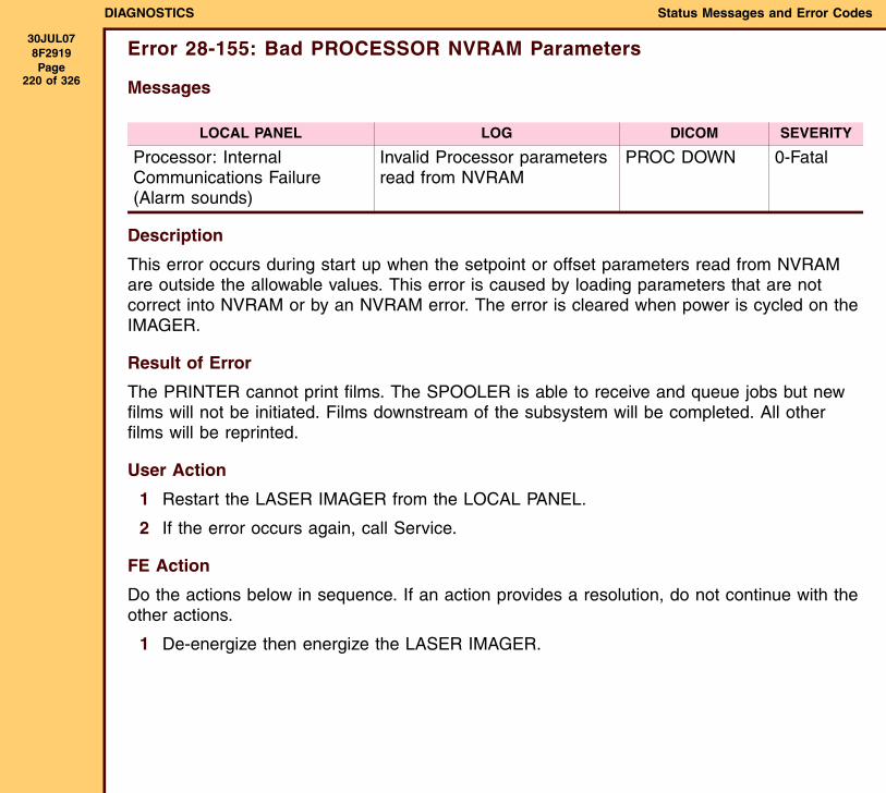
DIAGNOSTICS Status Messages and Error Codes
30JUL078F2919 Page
220 of 326
Error 28-155: Bad PROCESSOR NVRAM Parameters
Messages
Description
This error occurs during start up when the setpoint or offset parameters read from NVRAM are outside the allowable values. This error is caused by loading parameters that are not correct into NVRAM or by an NVRAM error. The error is cleared when power is cycled on the IMAGER.
Result of Error
The PRINTER cannot print films. The SPOOLER is able to receive and queue jobs but new films will not be initiated. Films downstream of the subsystem will be completed. All other films will be reprinted.
User Action
1 Restart the LASER IMAGER from the LOCAL PANEL.
2 If the error occurs again, call Service.
FE Action
Do the actions below in sequence. If an action provides a resolution, do not continue with the other actions.
1 De-energize then energize the LASER IMAGER.
LOCAL PANEL LOG DICOM SEVERITY
Processor: Internal Communications Failure(Alarm sounds)
Invalid Processor parameters read from NVRAM
PROC DOWN 0-Fatal
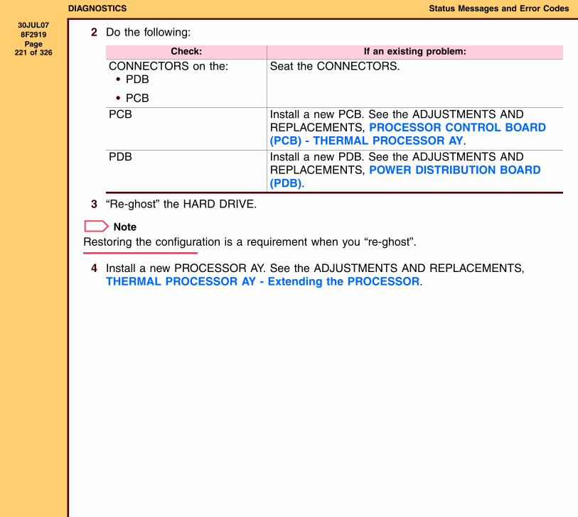
DIAGNOSTICS Status Messages and Error Codes
30JUL078F2919 Page
221 of 326
2 Do the following:
3 “Re-ghost” the HARD DRIVE.
NoteRestoring the configuration is a requirement when you “re-ghost”.
4 Install a new PROCESSOR AY. See the ADJUSTMENTS AND REPLACEMENTS, THERMAL PROCESSOR AY - Extending the PROCESSOR.
Check: If an existing problem:
CONNECTORS on the:• PDB
• PCB
Seat the CONNECTORS.
PCB Install a new PCB. See the ADJUSTMENTS AND REPLACEMENTS, PROCESSOR CONTROL BOARD (PCB) - THERMAL PROCESSOR AY.
PDB Install a new PDB. See the ADJUSTMENTS AND REPLACEMENTS, POWER DISTRIBUTION BOARD (PDB).
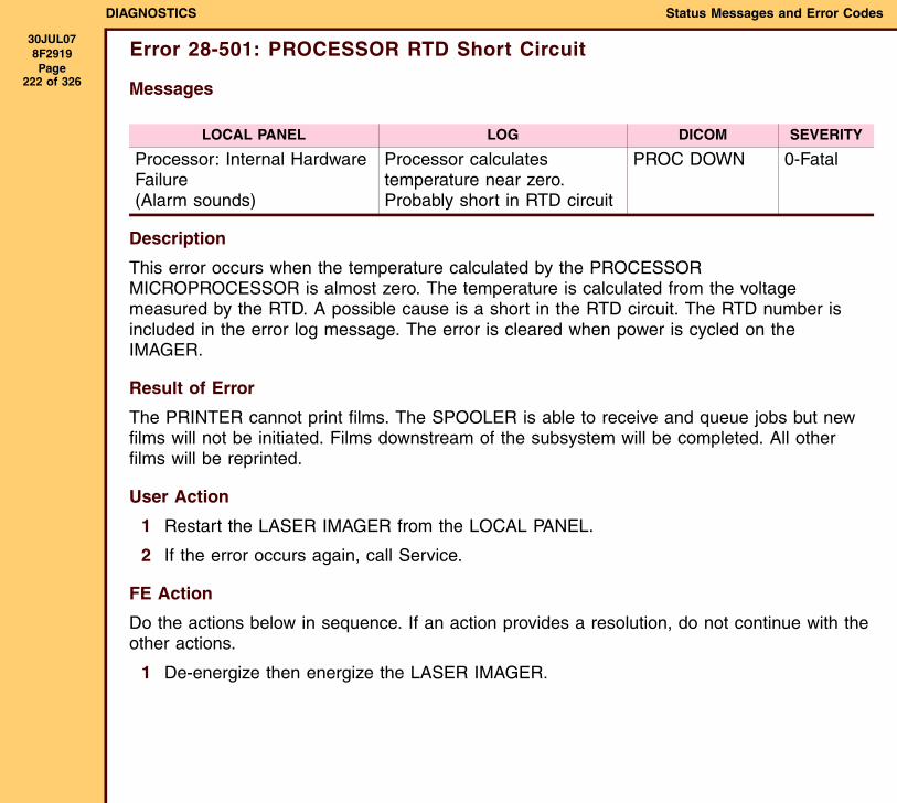
DIAGNOSTICS Status Messages and Error Codes
30JUL078F2919 Page
222 of 326
Error 28-501: PROCESSOR RTD Short Circuit
Messages
Description
This error occurs when the temperature calculated by the PROCESSOR MICROPROCESSOR is almost zero. The temperature is calculated from the voltage measured by the RTD. A possible cause is a short in the RTD circuit. The RTD number is included in the error log message. The error is cleared when power is cycled on the IMAGER.
Result of Error
The PRINTER cannot print films. The SPOOLER is able to receive and queue jobs but new films will not be initiated. Films downstream of the subsystem will be completed. All other films will be reprinted.
User Action
1 Restart the LASER IMAGER from the LOCAL PANEL.
2 If the error occurs again, call Service.
FE Action
Do the actions below in sequence. If an action provides a resolution, do not continue with the other actions.
1 De-energize then energize the LASER IMAGER.
LOCAL PANEL LOG DICOM SEVERITY
Processor: Internal Hardware Failure(Alarm sounds)
Processor calculates temperature near zero. Probably short in RTD circuit
PROC DOWN 0-Fatal

DIAGNOSTICS Status Messages and Error Codes
30JUL078F2919 Page
223 of 326
2 Do the following:
3 Install a new PROCESSOR AY. See the ADJUSTMENTS AND REPLACEMENTS, THERMAL PROCESSOR AY - Extending the PROCESSOR.
Check: If an existing problem:
CONNECTORS on the:• PDB
• PCB
Seat the CONNECTORS.
CIRCUIT BREAKER on the POWER SUPPLY
Engage the CIRCUIT BREAKER.
RTD settings - use the SERVICE TOOL
Install a new PROCESSOR AY. See the ADJUSTMENTS AND REPLACEMENTS, THERMAL PROCESSOR AY - Extending the PROCESSOR.
DRUM Install a new DRUM. See the ADJUSTMENTS AND REPLACEMENTS, DRUM AY - THERMAL PROCESSOR AY.
PCB Install a new PCB. See the ADJUSTMENTS AND REPLACEMENTS, PROCESSOR CONTROL BOARD (PCB) - THERMAL PROCESSOR AY.
PDB Install a new PDB. See the ADJUSTMENTS AND REPLACEMENTS, POWER DISTRIBUTION BOARD (PDB).
POWER MODULE Install a new POWER MODULE. See the ADJUSTMENTS AND REPLACEMENTS, POWER MODULE AY.
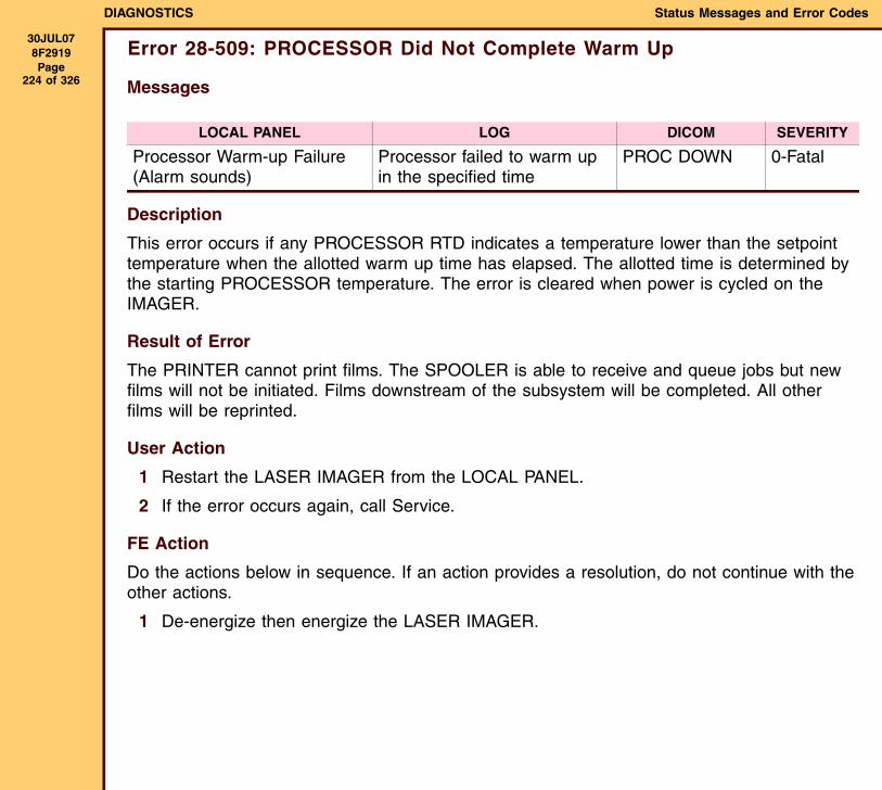
DIAGNOSTICS Status Messages and Error Codes
30JUL078F2919 Page
224 of 326
Error 28-509: PROCESSOR Did Not Complete Warm Up
Messages
Description
This error occurs if any PROCESSOR RTD indicates a temperature lower than the setpoint temperature when the allotted warm up time has elapsed. The allotted time is determined by the starting PROCESSOR temperature. The error is cleared when power is cycled on the IMAGER.
Result of Error
The PRINTER cannot print films. The SPOOLER is able to receive and queue jobs but new films will not be initiated. Films downstream of the subsystem will be completed. All other films will be reprinted.
User Action
1 Restart the LASER IMAGER from the LOCAL PANEL.
2 If the error occurs again, call Service.
FE Action
Do the actions below in sequence. If an action provides a resolution, do not continue with the other actions.
1 De-energize then energize the LASER IMAGER.
LOCAL PANEL LOG DICOM SEVERITY
Processor Warm-up Failure(Alarm sounds)
Processor failed to warm up in the specified time
PROC DOWN 0-Fatal

DIAGNOSTICS Status Messages and Error Codes
30JUL078F2919 Page
225 of 326
2 Do the following:
3 Install a new PROCESSOR AY. See the ADJUSTMENTS AND REPLACEMENTS, THERMAL PROCESSOR AY - Extending the PROCESSOR.
Check: If an existing problem:
CONNECTORS on the:• PDB
• PCB
Seat the CONNECTORS.
CIRCUIT BREAKER on the POWER SUPPLY
Engage the CIRCUIT BREAKER.
RTD settings - use the SERVICE TOOL
Install a new PROCESSOR AY. See the ADJUSTMENTS AND REPLACEMENTS, THERMAL PROCESSOR AY - Extending the PROCESSOR.
DRUM Install a new DRUM. See the ADJUSTMENTS AND REPLACEMENTS, DRUM AY - THERMAL PROCESSOR AY.
PCB Install a new PCB. See the ADJUSTMENTS AND REPLACEMENTS, PROCESSOR CONTROL BOARD (PCB) - THERMAL PROCESSOR AY.
PDB Install a new PDB. See the ADJUSTMENTS AND REPLACEMENTS, POWER DISTRIBUTION BOARD (PDB).
POWER MODULE Install a new POWER MODULE. See the ADJUSTMENTS AND REPLACEMENTS, POWER MODULE AY.
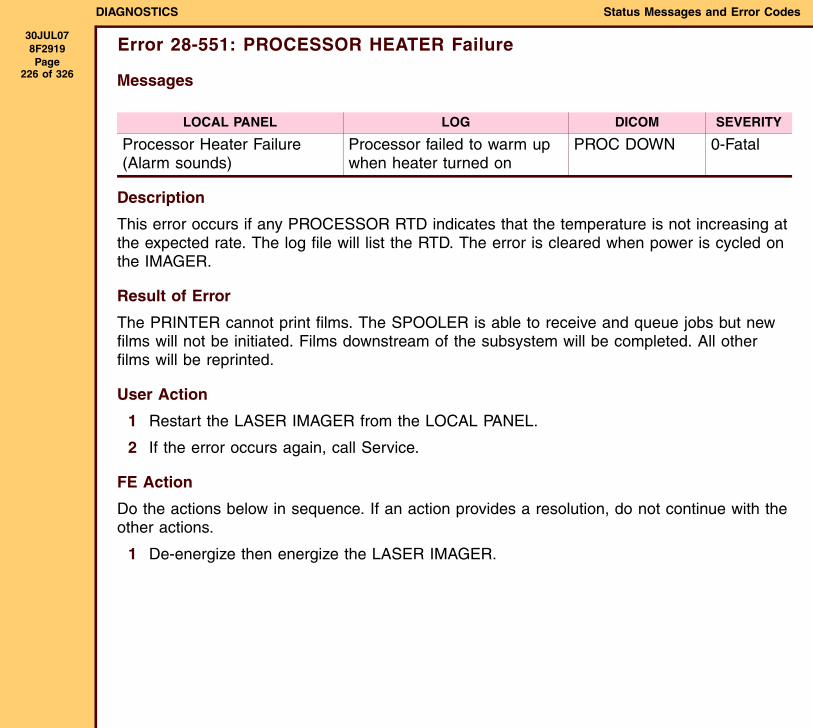
DIAGNOSTICS Status Messages and Error Codes
30JUL078F2919 Page
226 of 326
Error 28-551: PROCESSOR HEATER Failure
Messages
Description
This error occurs if any PROCESSOR RTD indicates that the temperature is not increasing at the expected rate. The log file will list the RTD. The error is cleared when power is cycled on the IMAGER.
Result of Error
The PRINTER cannot print films. The SPOOLER is able to receive and queue jobs but new films will not be initiated. Films downstream of the subsystem will be completed. All other films will be reprinted.
User Action
1 Restart the LASER IMAGER from the LOCAL PANEL.
2 If the error occurs again, call Service.
FE Action
Do the actions below in sequence. If an action provides a resolution, do not continue with the other actions.
1 De-energize then energize the LASER IMAGER.
LOCAL PANEL LOG DICOM SEVERITY
Processor Heater Failure(Alarm sounds)
Processor failed to warm up when heater turned on
PROC DOWN 0-Fatal
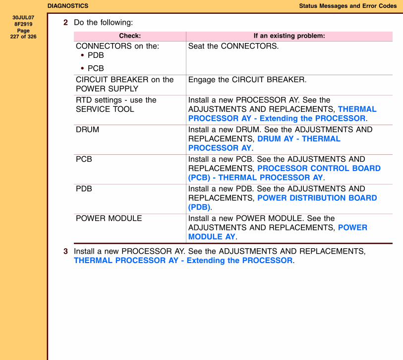
DIAGNOSTICS Status Messages and Error Codes
30JUL078F2919 Page
227 of 326
2 Do the following:
3 Install a new PROCESSOR AY. See the ADJUSTMENTS AND REPLACEMENTS, THERMAL PROCESSOR AY - Extending the PROCESSOR.
Check: If an existing problem:
CONNECTORS on the:• PDB
• PCB
Seat the CONNECTORS.
CIRCUIT BREAKER on the POWER SUPPLY
Engage the CIRCUIT BREAKER.
RTD settings - use the SERVICE TOOL
Install a new PROCESSOR AY. See the ADJUSTMENTS AND REPLACEMENTS, THERMAL PROCESSOR AY - Extending the PROCESSOR.
DRUM Install a new DRUM. See the ADJUSTMENTS AND REPLACEMENTS, DRUM AY - THERMAL PROCESSOR AY.
PCB Install a new PCB. See the ADJUSTMENTS AND REPLACEMENTS, PROCESSOR CONTROL BOARD (PCB) - THERMAL PROCESSOR AY.
PDB Install a new PDB. See the ADJUSTMENTS AND REPLACEMENTS, POWER DISTRIBUTION BOARD (PDB).
POWER MODULE Install a new POWER MODULE. See the ADJUSTMENTS AND REPLACEMENTS, POWER MODULE AY.
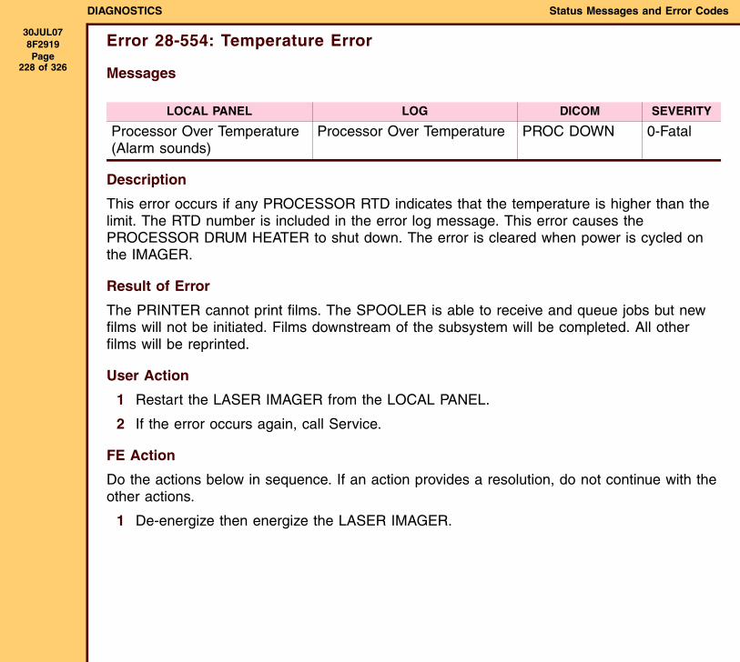
DIAGNOSTICS Status Messages and Error Codes
30JUL078F2919 Page
228 of 326
Error 28-554: Temperature Error
Messages
Description
This error occurs if any PROCESSOR RTD indicates that the temperature is higher than the limit. The RTD number is included in the error log message. This error causes the PROCESSOR DRUM HEATER to shut down. The error is cleared when power is cycled on the IMAGER.
Result of Error
The PRINTER cannot print films. The SPOOLER is able to receive and queue jobs but new films will not be initiated. Films downstream of the subsystem will be completed. All other films will be reprinted.
User Action
1 Restart the LASER IMAGER from the LOCAL PANEL.
2 If the error occurs again, call Service.
FE Action
Do the actions below in sequence. If an action provides a resolution, do not continue with the other actions.
1 De-energize then energize the LASER IMAGER.
LOCAL PANEL LOG DICOM SEVERITY
Processor Over Temperature(Alarm sounds)
Processor Over Temperature PROC DOWN 0-Fatal
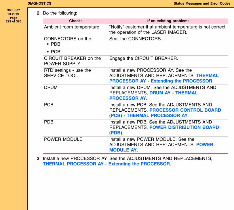
DIAGNOSTICS Status Messages and Error Codes
30JUL078F2919 Page
229 of 326
2 Do the following:
3 Install a new PROCESSOR AY. See the ADJUSTMENTS AND REPLACEMENTS, THERMAL PROCESSOR AY - Extending the PROCESSOR.
Check: If an existing problem:
Ambient room temperature “Notify” customer that ambient temperature is not correct the operation of the LASER IMAGER.
CONNECTORS on the:• PDB
• PCB
Seat the CONNECTORS.
CIRCUIT BREAKER on the POWER SUPPLY
Engage the CIRCUIT BREAKER.
RTD settings - use the SERVICE TOOL
Install a new PROCESSOR AY. See the ADJUSTMENTS AND REPLACEMENTS, THERMAL PROCESSOR AY - Extending the PROCESSOR.
DRUM Install a new DRUM. See the ADJUSTMENTS AND REPLACEMENTS, DRUM AY - THERMAL PROCESSOR AY.
PCB Install a new PCB. See the ADJUSTMENTS AND REPLACEMENTS, PROCESSOR CONTROL BOARD (PCB) - THERMAL PROCESSOR AY.
PDB Install a new PDB. See the ADJUSTMENTS AND REPLACEMENTS, POWER DISTRIBUTION BOARD (PDB).
POWER MODULE Install a new POWER MODULE. See the ADJUSTMENTS AND REPLACEMENTS, POWER MODULE AY.

DIAGNOSTICS Status Messages and Error Codes
30JUL078F2919 Page
230 of 326
Error 28-931: PROCESSOR Communications Failure
Messages
Description
This error occurs when the MCS tries to communicate with the MICROCONTROLLER but receives no response to 5 attempts. The error is cleared when power is cycled on the IMAGER.
Result of Error
The PRINTER cannot print films. The SPOOLER is able to receive and queue jobs but new films will not be initiated. Films downstream of the subsystem will be completed. All other films will be reprinted.
User Action
1 Restart the LASER IMAGER from the LOCAL PANEL.
2 If the error occurs again, call Service.
FE Action
Do the actions below in sequence. If an action provides a resolution, do not continue with the other actions.
1 De-energize then energize the LASER IMAGER.
LOCAL PANEL LOG DICOM SEVERITY
Processor: Internal Communications Failure(Alarm sounds)
MCS failed to communicate with the processor module after multiple attempts
ELEC DOWN 0-Fatal
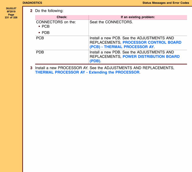
DIAGNOSTICS Status Messages and Error Codes
30JUL078F2919 Page
231 of 326
2 Do the following:
3 Install a new PROCESSOR AY. See the ADJUSTMENTS AND REPLACEMENTS, THERMAL PROCESSOR AY - Extending the PROCESSOR.
Check: If an existing problem:
CONNECTORS on the:• PCB
• PDB
Seat the CONNECTORS.
PCB Install a new PCB. See the ADJUSTMENTS AND REPLACEMENTS, PROCESSOR CONTROL BOARD (PCB) - THERMAL PROCESSOR AY.
PDB Install a new PDB. See the ADJUSTMENTS AND REPLACEMENTS, POWER DISTRIBUTION BOARD (PDB).
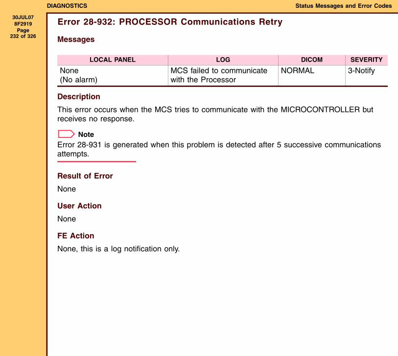
DIAGNOSTICS Status Messages and Error Codes
30JUL078F2919 Page
232 of 326
Error 28-932: PROCESSOR Communications Retry
Messages
Description
This error occurs when the MCS tries to communicate with the MICROCONTROLLER but receives no response.
NoteError 28-931 is generated when this problem is detected after 5 successive communications attempts.
Result of Error
None
User Action
None
FE Action
None, this is a log notification only.
LOCAL PANEL LOG DICOM SEVERITY
None(No alarm)
MCS failed to communicate with the Processor
NORMAL 3-Notify
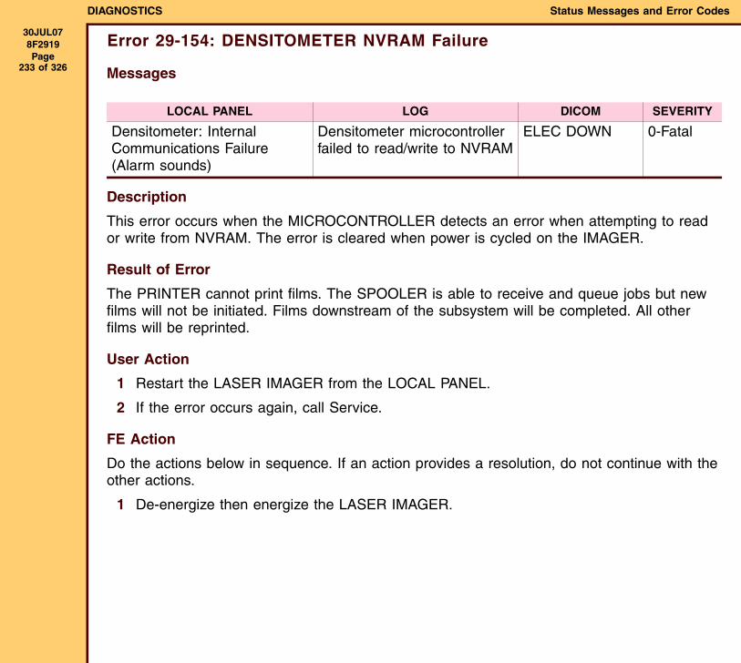
DIAGNOSTICS Status Messages and Error Codes
30JUL078F2919 Page
233 of 326
Error 29-154: DENSITOMETER NVRAM Failure
Messages
Description
This error occurs when the MICROCONTROLLER detects an error when attempting to read or write from NVRAM. The error is cleared when power is cycled on the IMAGER.
Result of Error
The PRINTER cannot print films. The SPOOLER is able to receive and queue jobs but new films will not be initiated. Films downstream of the subsystem will be completed. All other films will be reprinted.
User Action
1 Restart the LASER IMAGER from the LOCAL PANEL.
2 If the error occurs again, call Service.
FE Action
Do the actions below in sequence. If an action provides a resolution, do not continue with the other actions.
1 De-energize then energize the LASER IMAGER.
LOCAL PANEL LOG DICOM SEVERITY
Densitometer: Internal Communications Failure(Alarm sounds)
Densitometer microcontroller failed to read/write to NVRAM
ELEC DOWN 0-Fatal

DIAGNOSTICS Status Messages and Error Codes
30JUL078F2919 Page
234 of 326
2 Do the following:
3 Install a new TURNAROUND AY. See the ADJUSTMENTS AND REPLACEMENTS, TURNAROUND AY - IMAGER with SORTER.
Check: If an existing problem:
CONNECTORS on the:• PCB
• PDB
Seat the CONNECTORS.
PCB Install a new PCB. See the ADJUSTMENTS AND REPLACEMENTS, PROCESSOR CONTROL BOARD (PCB) - THERMAL PROCESSOR AY.
PDB Install a new PDB. See the ADJUSTMENTS AND REPLACEMENTS, POWER DISTRIBUTION BOARD (PDB).

DIAGNOSTICS Status Messages and Error Codes
30JUL078F2919 Page
235 of 326
Error 29-924: DENSITOMETER Failed Offset Reading Diagnostics
Messages
Description
During a calibration print and during DENSITOMETER diagnostics, a reading from the DENSITY SENSOR (S16) is taken with the light source turned off. The error is indicated if the reading out of range. The error is cleared when power is cycled on the IMAGER.
Result of Error
The PRINTER cannot print films. The SPOOLER is able to receive and queue jobs but new films will not be initiated. Films downstream of the subsystem will be completed. All other films will be reprinted.
User Action
1 Restart the LASER IMAGER from the LOCAL PANEL.
2 If the error occurs again, call Service.
FE Action
Do the actions below in sequence. If an action provides a resolution, do not continue with the other actions.
1 De-energize then energize the LASER IMAGER.
LOCAL PANEL LOG DICOM SEVERITY
Densitometer: Internal Diagnostics Failure(Alarm sounds)
Densitometer offset reading out of range with light source off
ELEC DOWN 0-Fatal
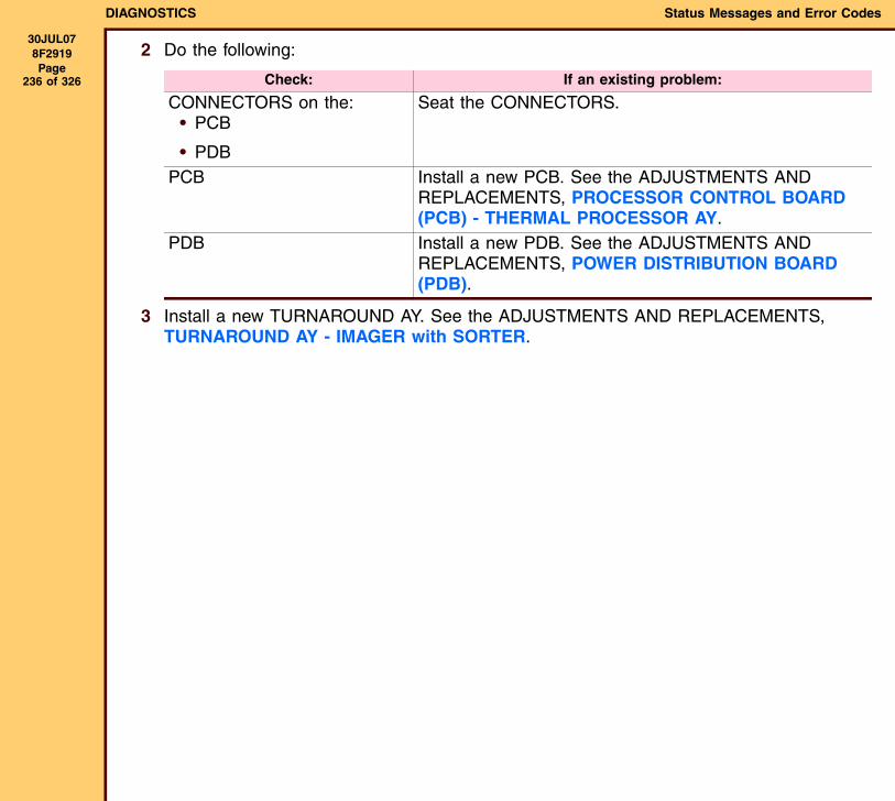
DIAGNOSTICS Status Messages and Error Codes
30JUL078F2919 Page
236 of 326
2 Do the following:
3 Install a new TURNAROUND AY. See the ADJUSTMENTS AND REPLACEMENTS, TURNAROUND AY - IMAGER with SORTER.
Check: If an existing problem:
CONNECTORS on the:• PCB
• PDB
Seat the CONNECTORS.
PCB Install a new PCB. See the ADJUSTMENTS AND REPLACEMENTS, PROCESSOR CONTROL BOARD (PCB) - THERMAL PROCESSOR AY.
PDB Install a new PDB. See the ADJUSTMENTS AND REPLACEMENTS, POWER DISTRIBUTION BOARD (PDB).
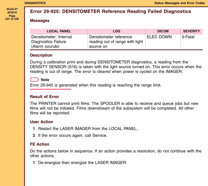
DIAGNOSTICS Status Messages and Error Codes
30JUL078F2919 Page
237 of 326
Error 29-925: DENSITOMETER Reference Reading Failed Diagnostics
Messages
Description
During a calibration print and during DENSITOMETER diagnostics, a reading from the DENSITY SENSOR (S16) is taken with the light source turned on. This error occurs when the reading is out of range. The error is cleared when power is cycled on the IMAGER.
NoteError 29-945 is generated when this reading is reaching the range limit.
Result of Error
The PRINTER cannot print films. The SPOOLER is able to receive and queue jobs but new films will not be initiated. Films downstream of the subsystem will be completed. All other films will be reprinted.
User Action
1 Restart the LASER IMAGER from the LOCAL PANEL.
2 If the error occurs again, call Service.
FE Action
Do the actions below in sequence. If an action provides a resolution, do not continue with the other actions.
1 De-energize then energize the LASER IMAGER.
LOCAL PANEL LOG DICOM SEVERITY
Densitometer: Internal Diagnostics Failure(Alarm sounds)
Densitometer reference reading out of range with light source on
ELEC DOWN 0-Fatal
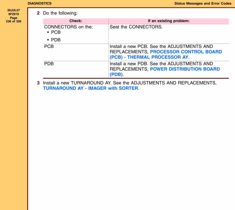
DIAGNOSTICS Status Messages and Error Codes
30JUL078F2919 Page
238 of 326
2 Do the following:
3 Install a new TURNAROUND AY. See the ADJUSTMENTS AND REPLACEMENTS, TURNAROUND AY - IMAGER with SORTER.
Check: If an existing problem:
CONNECTORS on the:• PCB
• PDB
Seat the CONNECTORS.
PCB Install a new PCB. See the ADJUSTMENTS AND REPLACEMENTS, PROCESSOR CONTROL BOARD (PCB) - THERMAL PROCESSOR AY.
PDB Install a new PDB. See the ADJUSTMENTS AND REPLACEMENTS, POWER DISTRIBUTION BOARD (PDB).
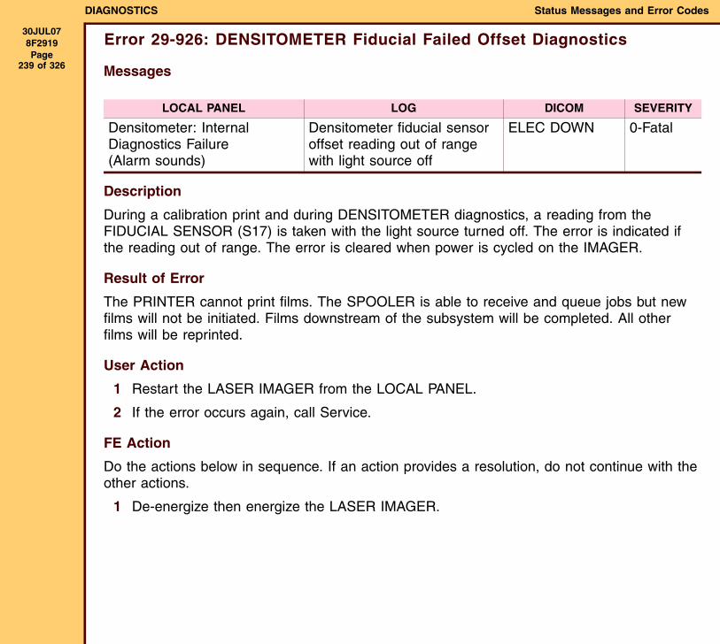
DIAGNOSTICS Status Messages and Error Codes
30JUL078F2919 Page
239 of 326
Error 29-926: DENSITOMETER Fiducial Failed Offset Diagnostics
Messages
Description
During a calibration print and during DENSITOMETER diagnostics, a reading from the FIDUCIAL SENSOR (S17) is taken with the light source turned off. The error is indicated if the reading out of range. The error is cleared when power is cycled on the IMAGER.
Result of Error
The PRINTER cannot print films. The SPOOLER is able to receive and queue jobs but new films will not be initiated. Films downstream of the subsystem will be completed. All other films will be reprinted.
User Action
1 Restart the LASER IMAGER from the LOCAL PANEL.
2 If the error occurs again, call Service.
FE Action
Do the actions below in sequence. If an action provides a resolution, do not continue with the other actions.
1 De-energize then energize the LASER IMAGER.
LOCAL PANEL LOG DICOM SEVERITY
Densitometer: Internal Diagnostics Failure(Alarm sounds)
Densitometer fiducial sensor offset reading out of range with light source off
ELEC DOWN 0-Fatal

DIAGNOSTICS Status Messages and Error Codes
30JUL078F2919 Page
240 of 326
2 Do the following:
3 Install a new TURNAROUND AY. See the ADJUSTMENTS AND REPLACEMENTS, TURNAROUND AY - IMAGER with SORTER.
Check: If an existing problem:
CONNECTORS on the:• PCB
• PDB
Seat the CONNECTORS.
PCB Install a new PCB. See the ADJUSTMENTS AND REPLACEMENTS, PROCESSOR CONTROL BOARD (PCB) - THERMAL PROCESSOR AY.
PDB Install a new PDB. See the ADJUSTMENTS AND REPLACEMENTS, POWER DISTRIBUTION BOARD (PDB).
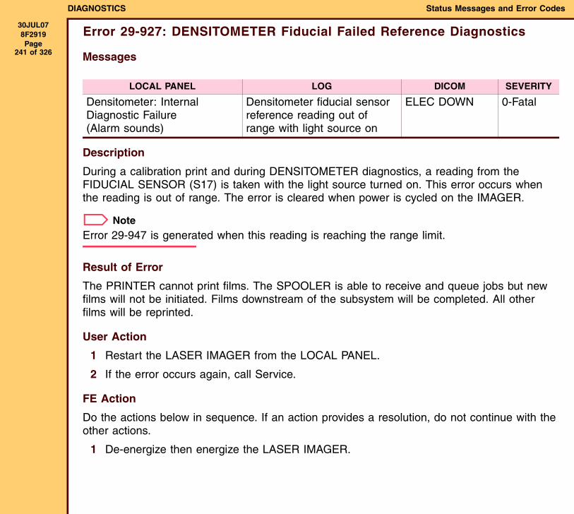
DIAGNOSTICS Status Messages and Error Codes
30JUL078F2919 Page
241 of 326
Error 29-927: DENSITOMETER Fiducial Failed Reference Diagnostics
Messages
Description
During a calibration print and during DENSITOMETER diagnostics, a reading from the FIDUCIAL SENSOR (S17) is taken with the light source turned on. This error occurs when the reading is out of range. The error is cleared when power is cycled on the IMAGER.
NoteError 29-947 is generated when this reading is reaching the range limit.
Result of Error
The PRINTER cannot print films. The SPOOLER is able to receive and queue jobs but new films will not be initiated. Films downstream of the subsystem will be completed. All other films will be reprinted.
User Action
1 Restart the LASER IMAGER from the LOCAL PANEL.
2 If the error occurs again, call Service.
FE Action
Do the actions below in sequence. If an action provides a resolution, do not continue with the other actions.
1 De-energize then energize the LASER IMAGER.
LOCAL PANEL LOG DICOM SEVERITY
Densitometer: Internal Diagnostic Failure(Alarm sounds)
Densitometer fiducial sensor reference reading out of range with light source on
ELEC DOWN 0-Fatal

DIAGNOSTICS Status Messages and Error Codes
30JUL078F2919 Page
242 of 326
2 Do the following:
3 Install a new TURNAROUND AY. See the ADJUSTMENTS AND REPLACEMENTS, TURNAROUND AY - IMAGER with SORTER.
Check: If an existing problem:
CONNECTORS on the:• PCB
• PDB
Seat the CONNECTORS.
PCB Install a new PCB. See the ADJUSTMENTS AND REPLACEMENTS, PROCESSOR CONTROL BOARD (PCB) - THERMAL PROCESSOR AY.
PDB Install a new PDB. See the ADJUSTMENTS AND REPLACEMENTS, POWER DISTRIBUTION BOARD (PDB).
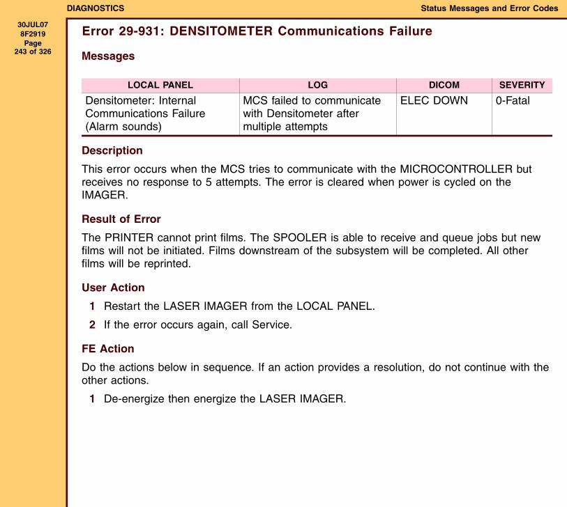
DIAGNOSTICS Status Messages and Error Codes
30JUL078F2919 Page
243 of 326
Error 29-931: DENSITOMETER Communications Failure
Messages
Description
This error occurs when the MCS tries to communicate with the MICROCONTROLLER but receives no response to 5 attempts. The error is cleared when power is cycled on the IMAGER.
Result of Error
The PRINTER cannot print films. The SPOOLER is able to receive and queue jobs but new films will not be initiated. Films downstream of the subsystem will be completed. All other films will be reprinted.
User Action
1 Restart the LASER IMAGER from the LOCAL PANEL.
2 If the error occurs again, call Service.
FE Action
Do the actions below in sequence. If an action provides a resolution, do not continue with the other actions.
1 De-energize then energize the LASER IMAGER.
LOCAL PANEL LOG DICOM SEVERITY
Densitometer: Internal Communications Failure(Alarm sounds)
MCS failed to communicate with Densitometer after multiple attempts
ELEC DOWN 0-Fatal

DIAGNOSTICS Status Messages and Error Codes
30JUL078F2919 Page
244 of 326
2 Do the following:
3 Install a new TURNAROUND AY. See the ADJUSTMENTS AND REPLACEMENTS, TURNAROUND AY - IMAGER with SORTER.
Check: If an existing problem:
CONNECTORS on the:• PCB
• PDB
Seat the CONNECTORS.
PCB Install a new PCB. See the ADJUSTMENTS AND REPLACEMENTS, PROCESSOR CONTROL BOARD (PCB) - THERMAL PROCESSOR AY.
PDB Install a new PDB. See the ADJUSTMENTS AND REPLACEMENTS, POWER DISTRIBUTION BOARD (PDB).
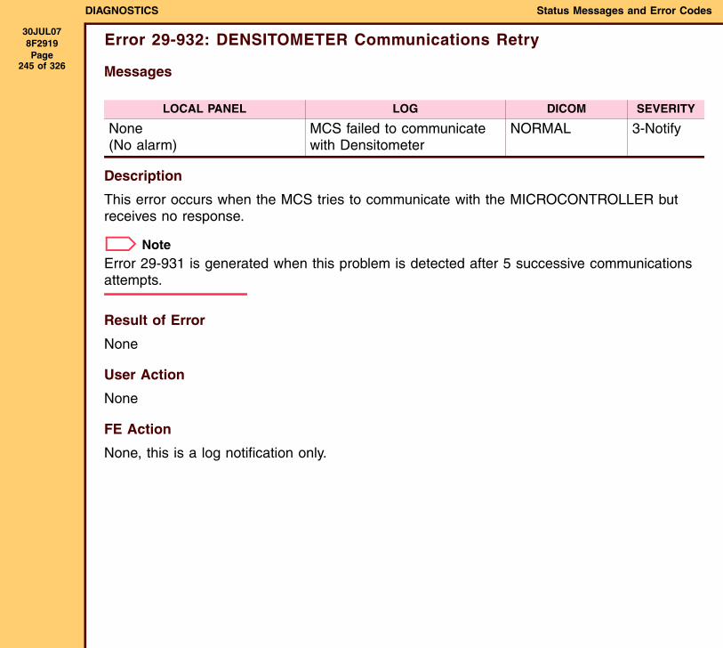
DIAGNOSTICS Status Messages and Error Codes
30JUL078F2919 Page
245 of 326
Error 29-932: DENSITOMETER Communications Retry
Messages
Description
This error occurs when the MCS tries to communicate with the MICROCONTROLLER but receives no response.
NoteError 29-931 is generated when this problem is detected after 5 successive communications attempts.
Result of Error
None
User Action
None
FE Action
None, this is a log notification only.
LOCAL PANEL LOG DICOM SEVERITY
None(No alarm)
MCS failed to communicate with Densitometer
NORMAL 3-Notify
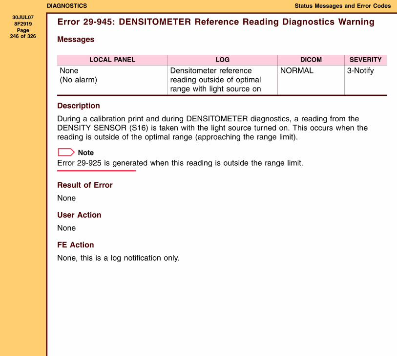
DIAGNOSTICS Status Messages and Error Codes
30JUL078F2919 Page
246 of 326
Error 29-945: DENSITOMETER Reference Reading Diagnostics Warning
Messages
Description
During a calibration print and during DENSITOMETER diagnostics, a reading from the DENSITY SENSOR (S16) is taken with the light source turned on. This occurs when the reading is outside of the optimal range (approaching the range limit).
NoteError 29-925 is generated when this reading is outside the range limit.
Result of Error
None
User Action
None
FE Action
None, this is a log notification only.
LOCAL PANEL LOG DICOM SEVERITY
None(No alarm)
Densitometer reference reading outside of optimal range with light source on
NORMAL 3-Notify
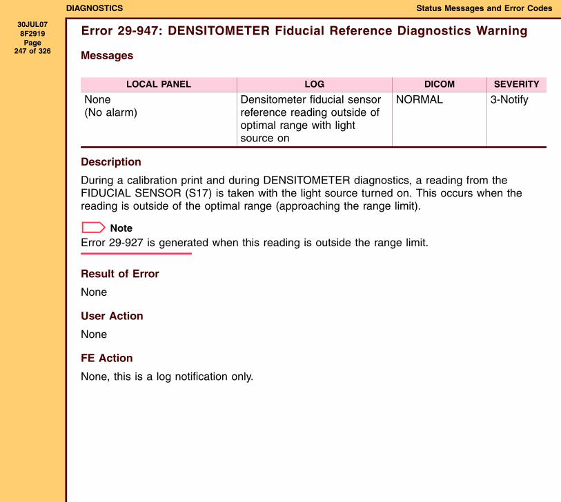
DIAGNOSTICS Status Messages and Error Codes
30JUL078F2919 Page
247 of 326
Error 29-947: DENSITOMETER Fiducial Reference Diagnostics Warning
Messages
Description
During a calibration print and during DENSITOMETER diagnostics, a reading from the FIDUCIAL SENSOR (S17) is taken with the light source turned on. This occurs when the reading is outside of the optimal range (approaching the range limit).
NoteError 29-927 is generated when this reading is outside the range limit.
Result of Error
None
User Action
None
FE Action
None, this is a log notification only.
LOCAL PANEL LOG DICOM SEVERITY
None(No alarm)
Densitometer fiducial sensor reference reading outside of optimal range with light source on
NORMAL 3-Notify
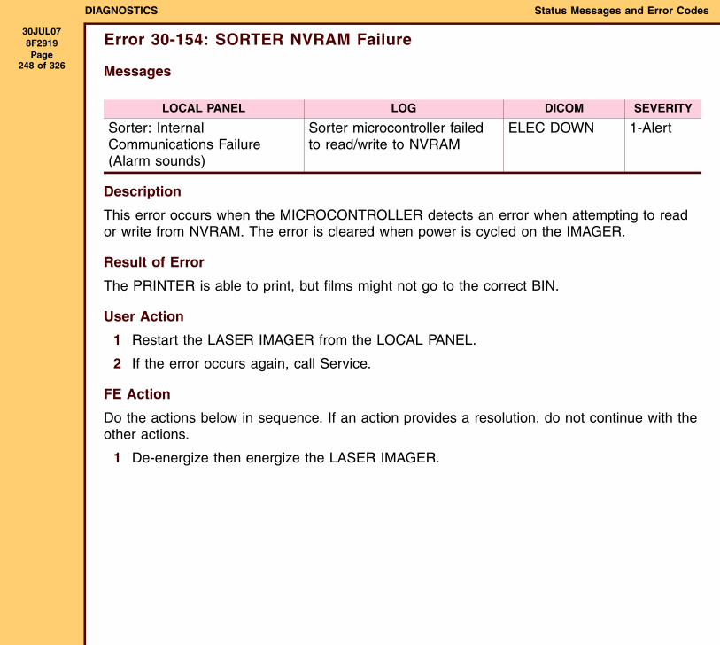
DIAGNOSTICS Status Messages and Error Codes
30JUL078F2919 Page
248 of 326
Error 30-154: SORTER NVRAM Failure
Messages
Description
This error occurs when the MICROCONTROLLER detects an error when attempting to read or write from NVRAM. The error is cleared when power is cycled on the IMAGER.
Result of Error
The PRINTER is able to print, but films might not go to the correct BIN.
User Action
1 Restart the LASER IMAGER from the LOCAL PANEL.
2 If the error occurs again, call Service.
FE Action
Do the actions below in sequence. If an action provides a resolution, do not continue with the other actions.
1 De-energize then energize the LASER IMAGER.
LOCAL PANEL LOG DICOM SEVERITY
Sorter: Internal Communications Failure(Alarm sounds)
Sorter microcontroller failed to read/write to NVRAM
ELEC DOWN 1-Alert
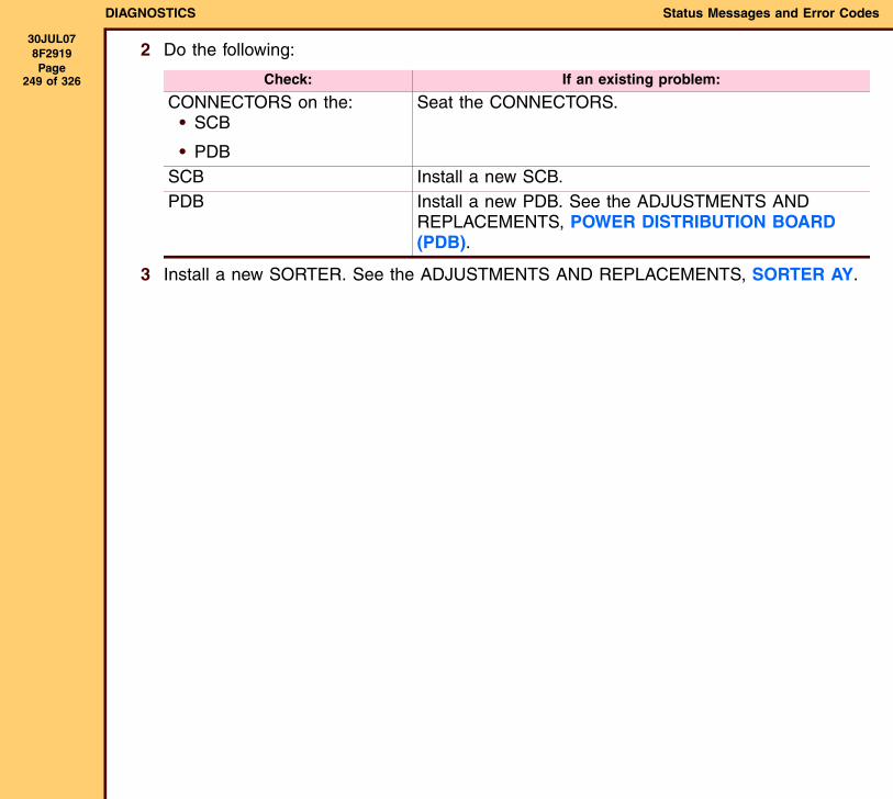
DIAGNOSTICS Status Messages and Error Codes
30JUL078F2919 Page
249 of 326
2 Do the following:
3 Install a new SORTER. See the ADJUSTMENTS AND REPLACEMENTS, SORTER AY.
Check: If an existing problem:
CONNECTORS on the:• SCB
• PDB
Seat the CONNECTORS.
SCB Install a new SCB.PDB Install a new PDB. See the ADJUSTMENTS AND
REPLACEMENTS, POWER DISTRIBUTION BOARD (PDB).
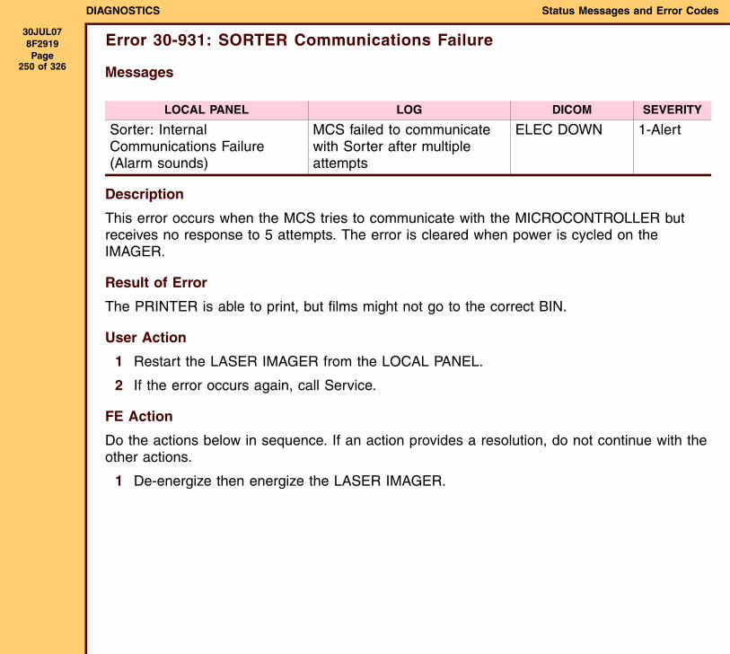
DIAGNOSTICS Status Messages and Error Codes
30JUL078F2919 Page
250 of 326
Error 30-931: SORTER Communications Failure
Messages
Description
This error occurs when the MCS tries to communicate with the MICROCONTROLLER but receives no response to 5 attempts. The error is cleared when power is cycled on the IMAGER.
Result of Error
The PRINTER is able to print, but films might not go to the correct BIN.
User Action
1 Restart the LASER IMAGER from the LOCAL PANEL.
2 If the error occurs again, call Service.
FE Action
Do the actions below in sequence. If an action provides a resolution, do not continue with the other actions.
1 De-energize then energize the LASER IMAGER.
LOCAL PANEL LOG DICOM SEVERITY
Sorter: Internal Communications Failure(Alarm sounds)
MCS failed to communicate with Sorter after multiple attempts
ELEC DOWN 1-Alert

DIAGNOSTICS Status Messages and Error Codes
30JUL078F2919 Page
251 of 326
2 Do the following:
3 Install a new SORTER. See the ADJUSTMENTS AND REPLACEMENTS, SORTER AY.
Check: If an existing problem:
CONNECTORS on the:• SCB
• PDB
Seat the CONNECTORS.
SCB Install a new SCB.PDB Install a new PDB. See the ADJUSTMENTS AND
REPLACEMENTS, POWER DISTRIBUTION BOARD (PDB).
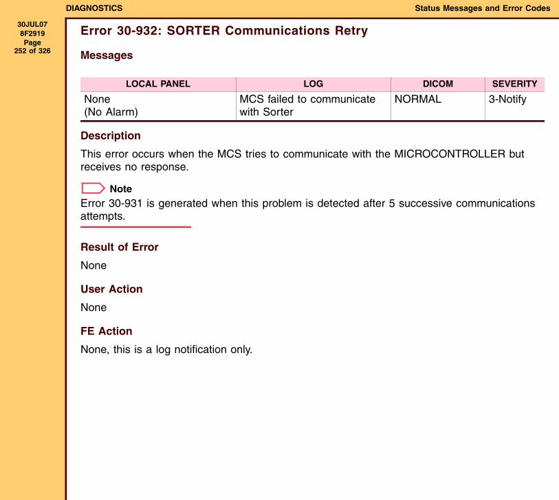
DIAGNOSTICS Status Messages and Error Codes
30JUL078F2919 Page
252 of 326
Error 30-932: SORTER Communications Retry
Messages
Description
This error occurs when the MCS tries to communicate with the MICROCONTROLLER but receives no response.
NoteError 30-931 is generated when this problem is detected after 5 successive communications attempts.
Result of Error
None
User Action
None
FE Action
None, this is a log notification only.
LOCAL PANEL LOG DICOM SEVERITY
None(No Alarm)
MCS failed to communicate with Sorter
NORMAL 3-Notify

DIAGNOSTICS Status Messages and Error Codes
30JUL078F2919 Page
253 of 326
Error 30-935: SORTER DIVERTER #1 Failure
Messages
Description
This error occurs when the SORTER DIVERTER ARM does not move, as determined by the DIVERTER BIN 1 POSITION SENSOR (S20). The error is cleared when power is cycled on the IMAGER.
Result of Error
The PRINTER is able to print, but films might not go to the correct BIN.
User Action
1 Restart the LASER IMAGER from the LOCAL PANEL.
2 If the error occurs again, call Service.
FE Action
Do the actions below in sequence. If an action provides a resolution, do not continue with the other actions.
1 De-energize then energize the LASER IMAGER.
LOCAL PANEL LOG DICOM SEVERITY
Sorter: Internal Hardware Failure(Alarm sounds)
Sorter Diverter #1 failed to operate
ELEC DOWN 1-Alert

DIAGNOSTICS Status Messages and Error Codes
30JUL078F2919 Page
254 of 326
2 Do the following:
3 Install a new SORTER. See the ADJUSTMENTS AND REPLACEMENTS, SORTER AY.
Check: If an existing problem:
CONNECTORS on the:• DIVERTER MOTOR
• SCB
• PDB
Seat the CONNECTORS.
DIVERTER MOTOR Install a new MOTOR. See the ADJUSTMENTS AND REPLACEMENTS, MOTOR (M16 - M19) - SORTER AY.
SCB Install a new SCB.PDB Install a new PDB. See the ADJUSTMENTS AND
REPLACEMENTS, POWER DISTRIBUTION BOARD (PDB).

DIAGNOSTICS Status Messages and Error Codes
30JUL078F2919 Page
255 of 326
Error 30-936: SORTER DIVERTER #2 Failure
Messages
Description
This error occurs when the SORTER DIVERTER ARM does not move, as determined by DIVERTER BIN 2 POSITION SENSOR (S21). The error is cleared when power is cycled on the IMAGER.
Result of Error
The PRINTER is able to print, but films might not go to the correct BIN.
User Action
1 Restart the LASER IMAGER from the LOCAL PANEL.
2 If the error occurs again, call Service.
FE Action
Do the actions below in sequence. If an action provides a resolution, do not continue with the other actions.
1 De-energize then energize the LASER IMAGER.
LOCAL PANEL LOG DICOM SEVERITY
Sorter: Internal Hardware Failure(Alarm sounds)
Sorter Diverter #2 failed to operate
ELEC DOWN 1-Alert

DIAGNOSTICS Status Messages and Error Codes
30JUL078F2919 Page
256 of 326
2 Do the following:
3 Install a new SORTER. See the ADJUSTMENTS AND REPLACEMENTS, SORTER AY.
Check: If an existing problem:
CONNECTORS on the:• DIVERTER MOTOR
• SCB
• PDB
Seat the CONNECTORS.
DIVERTER MOTOR Install a new MOTOR. See the ADJUSTMENTS AND REPLACEMENTS, MOTOR (M16 - M19) - SORTER AY
SCB Install a new SCB.PDB Install a new PDB. See the ADJUSTMENTS AND
REPLACEMENTS, POWER DISTRIBUTION BOARD (PDB).

DIAGNOSTICS Status Messages and Error Codes
30JUL078F2919 Page
257 of 326
Error 30-937: SORTER DIVERTER #3 Failure
Messages
Description
This error occurs when the SORTER DIVERTER ARM does not move, as determined by DIVERTER BIN 3 POSITION SENSOR (S22). The error is cleared when power is cycled on the IMAGER.
Result of Error
The PRINTER is able to print, but films might not go to the correct BIN.
User Action
1 Restart the LASER IMAGER from the LOCAL PANEL.
2 If the error occurs again, call Service.
FE Action
Do the actions below in sequence. If an action provides a resolution, do not continue with the other actions.
1 De-energize then energize the LASER IMAGER.
LOCAL PANEL LOG DICOM SEVERITY
Sorter: Internal Hardware Failure(Alarm sounds)
Sorter Diverter #3 failed to operate
ELEC DOWN 1-Alert
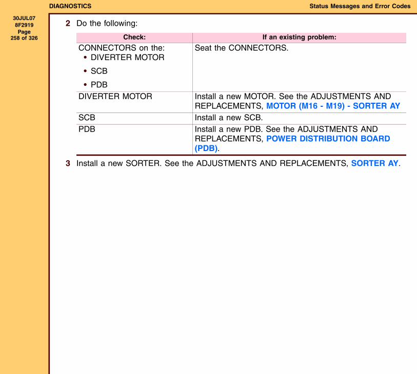
DIAGNOSTICS Status Messages and Error Codes
30JUL078F2919 Page
258 of 326
2 Do the following:
3 Install a new SORTER. See the ADJUSTMENTS AND REPLACEMENTS, SORTER AY.
Check: If an existing problem:
CONNECTORS on the:• DIVERTER MOTOR
• SCB
• PDB
Seat the CONNECTORS.
DIVERTER MOTOR Install a new MOTOR. See the ADJUSTMENTS AND REPLACEMENTS, MOTOR (M16 - M19) - SORTER AY
SCB Install a new SCB.PDB Install a new PDB. See the ADJUSTMENTS AND
REPLACEMENTS, POWER DISTRIBUTION BOARD (PDB).
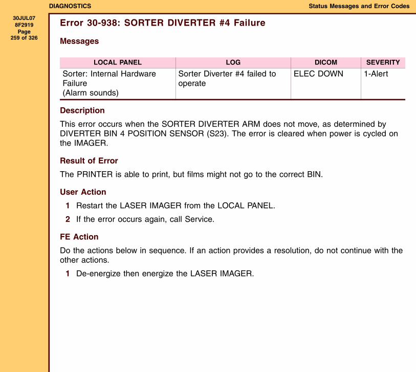
DIAGNOSTICS Status Messages and Error Codes
30JUL078F2919 Page
259 of 326
Error 30-938: SORTER DIVERTER #4 Failure
Messages
Description
This error occurs when the SORTER DIVERTER ARM does not move, as determined by DIVERTER BIN 4 POSITION SENSOR (S23). The error is cleared when power is cycled on the IMAGER.
Result of Error
The PRINTER is able to print, but films might not go to the correct BIN.
User Action
1 Restart the LASER IMAGER from the LOCAL PANEL.
2 If the error occurs again, call Service.
FE Action
Do the actions below in sequence. If an action provides a resolution, do not continue with the other actions.
1 De-energize then energize the LASER IMAGER.
LOCAL PANEL LOG DICOM SEVERITY
Sorter: Internal Hardware Failure(Alarm sounds)
Sorter Diverter #4 failed to operate
ELEC DOWN 1-Alert

DIAGNOSTICS Status Messages and Error Codes
30JUL078F2919 Page
260 of 326
2 Do the following:
3 Install a new SORTER. See the ADJUSTMENTS AND REPLACEMENTS, SORTER AY.
Check: If an existing problem:
CONNECTORS on the:• DIVERTER MOTOR
• SCB
• PDB
Seat the CONNECTORS.
DIVERTER MOTOR Install a new MOTOR. See the ADJUSTMENTS AND REPLACEMENTS, MOTOR (M16 - M19) - SORTER AY
SCB Install a new SCB.PDB Install a new PDB. See the ADJUSTMENTS AND
REPLACEMENTS, POWER DISTRIBUTION BOARD (PDB).
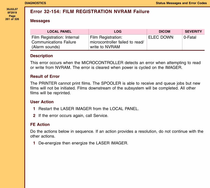
DIAGNOSTICS Status Messages and Error Codes
30JUL078F2919 Page
261 of 326
Error 32-154: FILM REGISTRATION NVRAM Failure
Messages
Description
This error occurs when the MICROCONTROLLER detects an error when attempting to read or write from NVRAM. The error is cleared when power is cycled on the IMAGER.
Result of Error
The PRINTER cannot print films. The SPOOLER is able to receive and queue jobs but new films will not be initiated. Films downstream of the subsystem will be completed. All other films will be reprinted.
User Action
1 Restart the LASER IMAGER from the LOCAL PANEL.
2 If the error occurs again, call Service.
FE Action
Do the actions below in sequence. If an action provides a resolution, do not continue with the other actions.
1 De-energize then energize the LASER IMAGER.
LOCAL PANEL LOG DICOM SEVERITY
Film Registration: Internal Communications Failure(Alarm sounds)
Film Registration: microcontroller failed to read/write to NVRAM
ELEC DOWN 0-Fatal
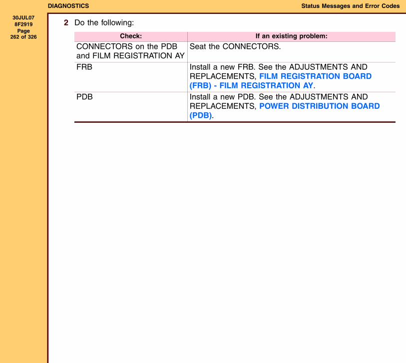
DIAGNOSTICS Status Messages and Error Codes
30JUL078F2919 Page
262 of 326
2 Do the following:
Check: If an existing problem:
CONNECTORS on the PDB and FILM REGISTRATION AY
Seat the CONNECTORS.
FRB Install a new FRB. See the ADJUSTMENTS AND REPLACEMENTS, FILM REGISTRATION BOARD (FRB) - FILM REGISTRATION AY.
PDB Install a new PDB. See the ADJUSTMENTS AND REPLACEMENTS, POWER DISTRIBUTION BOARD (PDB).

DIAGNOSTICS Status Messages and Error Codes
30JUL078F2919 Page
263 of 326
Error 32-301: FILM REGISTRATION Centering Failure
Messages
Description
This error occurs when the REGISTRATION CENTERING HOME SENSOR (S10) does not detect successful position of the CENTERING ARMS by the CENTERING MOTOR (M7). This error can occur at multiple points in the FILM REGISTRATION. The film will not be exposed, but will be moved out of the IMAGER. The error is cleared when power is cycled on the IMAGER.
Result of Error
The PRINTER cannot print films. The SPOOLER is able to receive and queue jobs but new films will not be initiated. Films downstream of the subsystem will be completed. All other films will be reprinted.
User Action
1 Restart the LASER IMAGER from the LOCAL PANEL.
2 If the error occurs again, call Service.
FE Action
Do the actions below in sequence. If an action provides a resolution, do not continue with the other actions.
1 De-energize then energize the LASER IMAGER.
LOCAL PANEL LOG DICOM SEVERITY
Film Registration Failure(Alarm sounds)
Film Registration Centering Failure: Centering Home sensor S10 indicates Centering motor M7 failure
FILM TRANS ERR
1-Alert
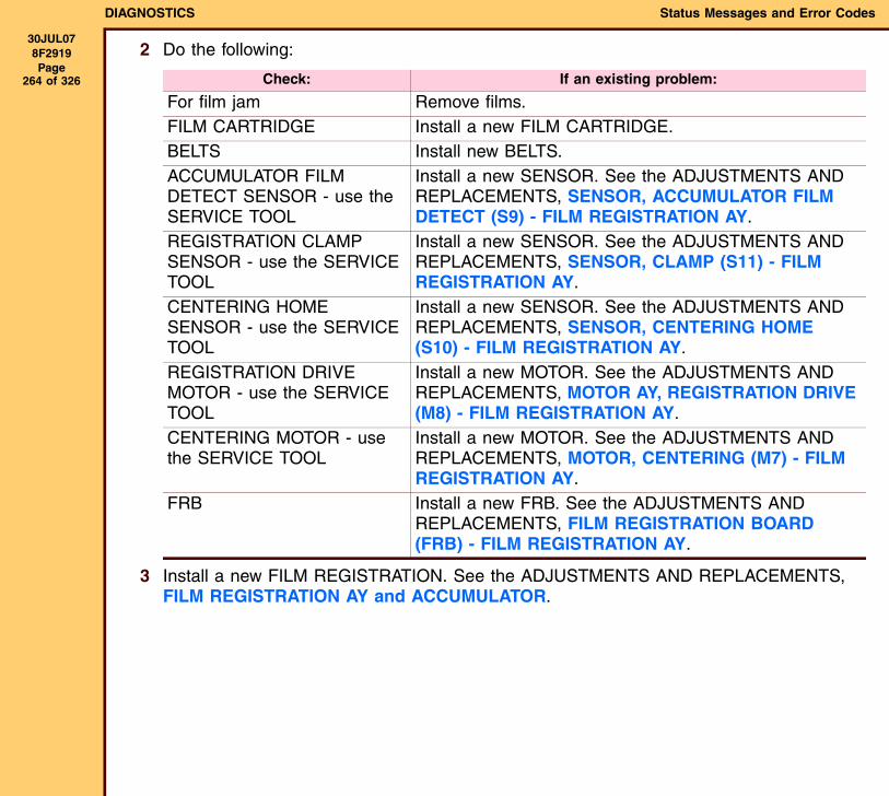
DIAGNOSTICS Status Messages and Error Codes
30JUL078F2919 Page
264 of 326
2 Do the following:
3 Install a new FILM REGISTRATION. See the ADJUSTMENTS AND REPLACEMENTS, FILM REGISTRATION AY and ACCUMULATOR.
Check: If an existing problem:
For film jam Remove films.FILM CARTRIDGE Install a new FILM CARTRIDGE.BELTS Install new BELTS.ACCUMULATOR FILM DETECT SENSOR - use the SERVICE TOOL
Install a new SENSOR. See the ADJUSTMENTS AND REPLACEMENTS, SENSOR, ACCUMULATOR FILM DETECT (S9) - FILM REGISTRATION AY.
REGISTRATION CLAMP SENSOR - use the SERVICE TOOL
Install a new SENSOR. See the ADJUSTMENTS AND REPLACEMENTS, SENSOR, CLAMP (S11) - FILM REGISTRATION AY.
CENTERING HOME SENSOR - use the SERVICE TOOL
Install a new SENSOR. See the ADJUSTMENTS AND REPLACEMENTS, SENSOR, CENTERING HOME (S10) - FILM REGISTRATION AY.
REGISTRATION DRIVE MOTOR - use the SERVICE TOOL
Install a new MOTOR. See the ADJUSTMENTS AND REPLACEMENTS, MOTOR AY, REGISTRATION DRIVE (M8) - FILM REGISTRATION AY.
CENTERING MOTOR - use the SERVICE TOOL
Install a new MOTOR. See the ADJUSTMENTS AND REPLACEMENTS, MOTOR, CENTERING (M7) - FILM REGISTRATION AY.
FRB Install a new FRB. See the ADJUSTMENTS AND REPLACEMENTS, FILM REGISTRATION BOARD (FRB) - FILM REGISTRATION AY.
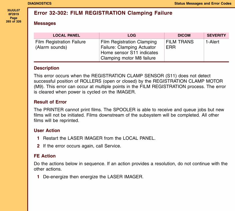
DIAGNOSTICS Status Messages and Error Codes
30JUL078F2919 Page
265 of 326
Error 32-302: FILM REGISTRATION Clamping Failure
Messages
Description
This error occurs when the REGISTRATION CLAMP SENSOR (S11) does not detect successful position of ROLLERS (open or closed) by the REGISTRATION CLAMP MOTOR (M9). This error can occur at multiple points in the FILM REGISTRATION process. The error is cleared when power is cycled on the IMAGER.
Result of Error
The PRINTER cannot print films. The SPOOLER is able to receive and queue jobs but new films will not be initiated. Films downstream of the subsystem will be completed. All other films will be reprinted.
User Action
1 Restart the LASER IMAGER from the LOCAL PANEL.
2 If the error occurs again, call Service.
FE Action
Do the actions below in sequence. If an action provides a resolution, do not continue with the other actions.
1 De-energize then energize the LASER IMAGER.
LOCAL PANEL LOG DICOM SEVERITY
Film Registration Failure(Alarm sounds)
Film Registration Clamping Failure: Clamping Actuator Home sensor S11 indicates Clamping motor M8 failure
FILM TRANS ERR
1-Alert
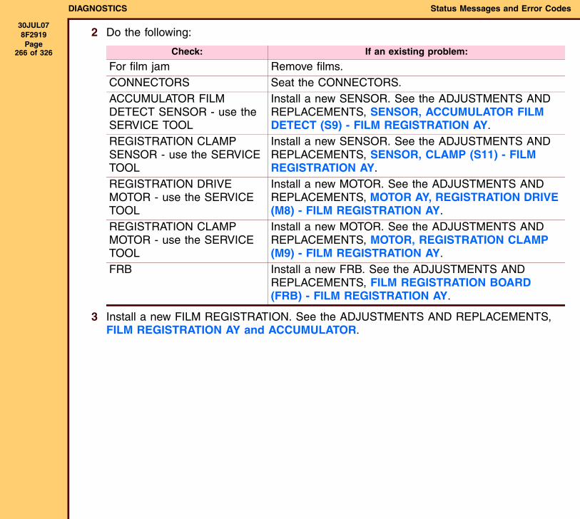
DIAGNOSTICS Status Messages and Error Codes
30JUL078F2919 Page
266 of 326
2 Do the following:
3 Install a new FILM REGISTRATION. See the ADJUSTMENTS AND REPLACEMENTS, FILM REGISTRATION AY and ACCUMULATOR.
Check: If an existing problem:
For film jam Remove films.CONNECTORS Seat the CONNECTORS.ACCUMULATOR FILM DETECT SENSOR - use the SERVICE TOOL
Install a new SENSOR. See the ADJUSTMENTS AND REPLACEMENTS, SENSOR, ACCUMULATOR FILM DETECT (S9) - FILM REGISTRATION AY.
REGISTRATION CLAMP SENSOR - use the SERVICE TOOL
Install a new SENSOR. See the ADJUSTMENTS AND REPLACEMENTS, SENSOR, CLAMP (S11) - FILM REGISTRATION AY.
REGISTRATION DRIVE MOTOR - use the SERVICE TOOL
Install a new MOTOR. See the ADJUSTMENTS AND REPLACEMENTS, MOTOR AY, REGISTRATION DRIVE (M8) - FILM REGISTRATION AY.
REGISTRATION CLAMP MOTOR - use the SERVICE TOOL
Install a new MOTOR. See the ADJUSTMENTS AND REPLACEMENTS, MOTOR, REGISTRATION CLAMP (M9) - FILM REGISTRATION AY.
FRB Install a new FRB. See the ADJUSTMENTS AND REPLACEMENTS, FILM REGISTRATION BOARD (FRB) - FILM REGISTRATION AY.
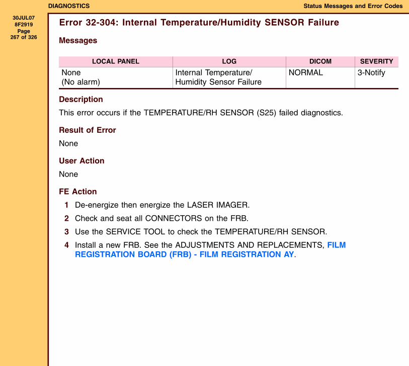
DIAGNOSTICS Status Messages and Error Codes
30JUL078F2919 Page
267 of 326
Error 32-304: Internal Temperature/Humidity SENSOR Failure
Messages
Description
This error occurs if the TEMPERATURE/RH SENSOR (S25) failed diagnostics.
Result of Error
None
User Action
None
FE Action
1 De-energize then energize the LASER IMAGER.
2 Check and seat all CONNECTORS on the FRB.
3 Use the SERVICE TOOL to check the TEMPERATURE/RH SENSOR.
4 Install a new FRB. See the ADJUSTMENTS AND REPLACEMENTS, FILM REGISTRATION BOARD (FRB) - FILM REGISTRATION AY.
LOCAL PANEL LOG DICOM SEVERITY
None(No alarm)
Internal Temperature/Humidity Sensor Failure
NORMAL 3-Notify
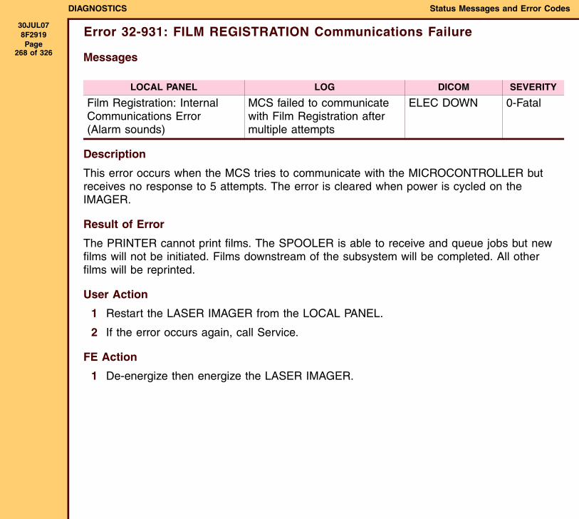
DIAGNOSTICS Status Messages and Error Codes
30JUL078F2919 Page
268 of 326
Error 32-931: FILM REGISTRATION Communications Failure
Messages
Description
This error occurs when the MCS tries to communicate with the MICROCONTROLLER but receives no response to 5 attempts. The error is cleared when power is cycled on the IMAGER.
Result of Error
The PRINTER cannot print films. The SPOOLER is able to receive and queue jobs but new films will not be initiated. Films downstream of the subsystem will be completed. All other films will be reprinted.
User Action
1 Restart the LASER IMAGER from the LOCAL PANEL.
2 If the error occurs again, call Service.
FE Action
1 De-energize then energize the LASER IMAGER.
LOCAL PANEL LOG DICOM SEVERITY
Film Registration: Internal Communications Error(Alarm sounds)
MCS failed to communicate with Film Registration after multiple attempts
ELEC DOWN 0-Fatal

DIAGNOSTICS Status Messages and Error Codes
30JUL078F2919 Page
269 of 326
2 Do the following:
Check: If an existing problem:
CONNECTORS on the PDB and FILM REGISTRATION AY
Seat the CONNECTORS.
FRB Install a new FRB. See the ADJUSTMENTS AND REPLACEMENTS, FILM REGISTRATION BOARD (FRB) - FILM REGISTRATION AY.
PDB Install a new PDB. See the ADJUSTMENTS AND REPLACEMENTS, POWER DISTRIBUTION BOARD (PDB).
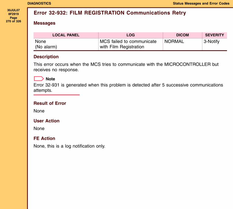
DIAGNOSTICS Status Messages and Error Codes
30JUL078F2919 Page
270 of 326
Error 32-932: FILM REGISTRATION Communications Retry
Messages
Description
This error occurs when the MCS tries to communicate with the MICROCONTROLLER but receives no response.
NoteError 32-931 is generated when this problem is detected after 5 successive communications attempts.
Result of Error
None
User Action
None
FE Action
None, this is a log notification only.
LOCAL PANEL LOG DICOM SEVERITY
None(No alarm)
MCS failed to communicate with Film Registration
NORMAL 3-Notify
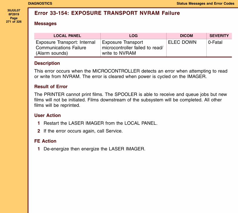
DIAGNOSTICS Status Messages and Error Codes
30JUL078F2919 Page
271 of 326
Error 33-154: EXPOSURE TRANSPORT NVRAM Failure
Messages
Description
This error occurs when the MICROCONTROLLER detects an error when attempting to read or write from NVRAM. The error is cleared when power is cycled on the IMAGER.
Result of Error
The PRINTER cannot print films. The SPOOLER is able to receive and queue jobs but new films will not be initiated. Films downstream of the subsystem will be completed. All other films will be reprinted.
User Action
1 Restart the LASER IMAGER from the LOCAL PANEL.
2 If the error occurs again, call Service.
FE Action
1 De-energize then energize the LASER IMAGER.
LOCAL PANEL LOG DICOM SEVERITY
Exposure Transport: Internal Communications Failure(Alarm sounds)
Exposure Transport microcontroller failed to read/write to NVRAM
ELEC DOWN 0-Fatal
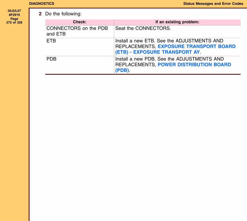
DIAGNOSTICS Status Messages and Error Codes
30JUL078F2919 Page
272 of 326
2 Do the following:
Check: If an existing problem:
CONNECTORS on the PDB and ETB
Seat the CONNECTORS.
ETB Install a new ETB. See the ADJUSTMENTS AND REPLACEMENTS, EXPOSURE TRANSPORT BOARD (ETB) - EXPOSURE TRANSPORT AY.
PDB Install a new PDB. See the ADJUSTMENTS AND REPLACEMENTS, POWER DISTRIBUTION BOARD (PDB).
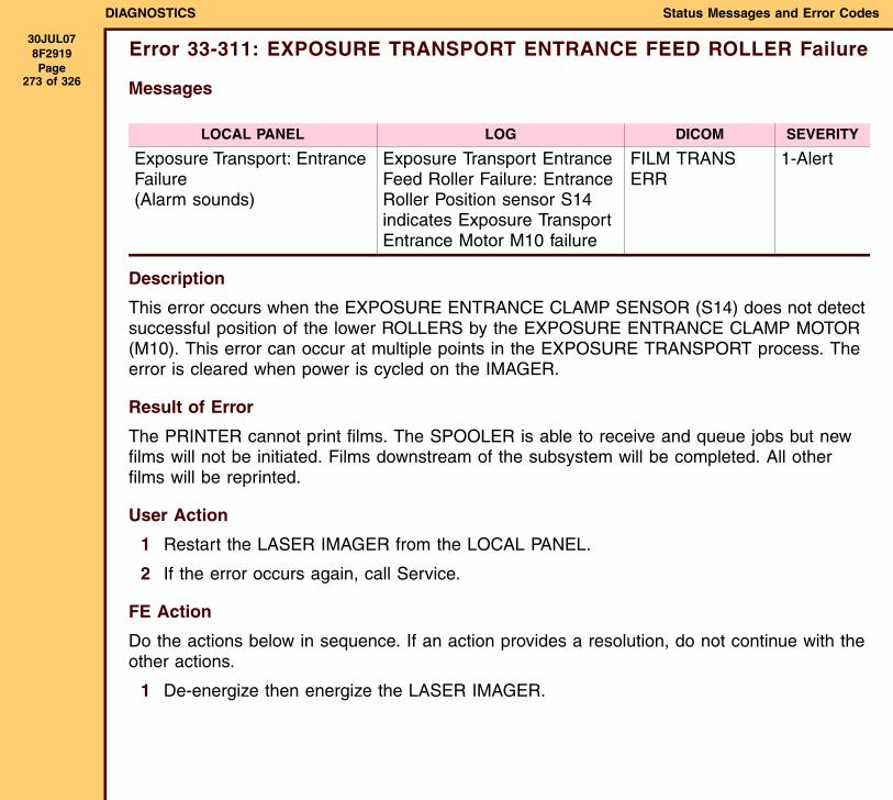
DIAGNOSTICS Status Messages and Error Codes
30JUL078F2919 Page
273 of 326
Error 33-311: EXPOSURE TRANSPORT ENTRANCE FEED ROLLER Failure
Messages
Description
This error occurs when the EXPOSURE ENTRANCE CLAMP SENSOR (S14) does not detect successful position of the lower ROLLERS by the EXPOSURE ENTRANCE CLAMP MOTOR (M10). This error can occur at multiple points in the EXPOSURE TRANSPORT process. The error is cleared when power is cycled on the IMAGER.
Result of Error
The PRINTER cannot print films. The SPOOLER is able to receive and queue jobs but new films will not be initiated. Films downstream of the subsystem will be completed. All other films will be reprinted.
User Action
1 Restart the LASER IMAGER from the LOCAL PANEL.
2 If the error occurs again, call Service.
FE Action
Do the actions below in sequence. If an action provides a resolution, do not continue with the other actions.
1 De-energize then energize the LASER IMAGER.
LOCAL PANEL LOG DICOM SEVERITY
Exposure Transport: Entrance Failure(Alarm sounds)
Exposure Transport Entrance Feed Roller Failure: Entrance Roller Position sensor S14 indicates Exposure Transport Entrance Motor M10 failure
FILM TRANS ERR
1-Alert
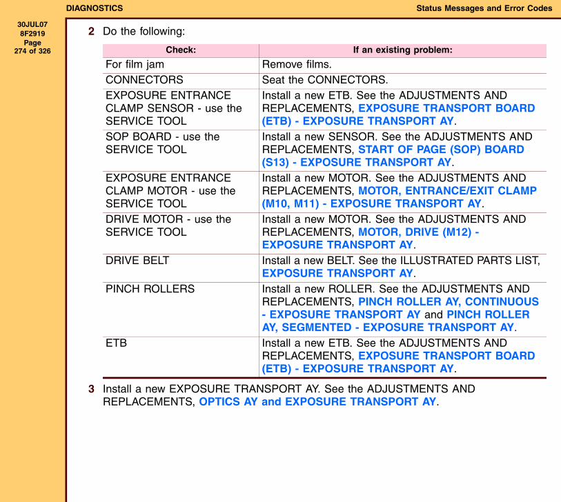
DIAGNOSTICS Status Messages and Error Codes
30JUL078F2919 Page
274 of 326
2 Do the following:
3 Install a new EXPOSURE TRANSPORT AY. See the ADJUSTMENTS AND REPLACEMENTS, OPTICS AY and EXPOSURE TRANSPORT AY.
Check: If an existing problem:
For film jam Remove films.CONNECTORS Seat the CONNECTORS.EXPOSURE ENTRANCE CLAMP SENSOR - use the SERVICE TOOL
Install a new ETB. See the ADJUSTMENTS AND REPLACEMENTS, EXPOSURE TRANSPORT BOARD (ETB) - EXPOSURE TRANSPORT AY.
SOP BOARD - use the SERVICE TOOL
Install a new SENSOR. See the ADJUSTMENTS AND REPLACEMENTS, START OF PAGE (SOP) BOARD (S13) - EXPOSURE TRANSPORT AY.
EXPOSURE ENTRANCE CLAMP MOTOR - use the SERVICE TOOL
Install a new MOTOR. See the ADJUSTMENTS AND REPLACEMENTS, MOTOR, ENTRANCE/EXIT CLAMP (M10, M11) - EXPOSURE TRANSPORT AY.
DRIVE MOTOR - use the SERVICE TOOL
Install a new MOTOR. See the ADJUSTMENTS AND REPLACEMENTS, MOTOR, DRIVE (M12) - EXPOSURE TRANSPORT AY.
DRIVE BELT Install a new BELT. See the ILLUSTRATED PARTS LIST, EXPOSURE TRANSPORT AY.
PINCH ROLLERS Install a new ROLLER. See the ADJUSTMENTS AND REPLACEMENTS, PINCH ROLLER AY, CONTINUOUS - EXPOSURE TRANSPORT AY and PINCH ROLLER AY, SEGMENTED - EXPOSURE TRANSPORT AY.
ETB Install a new ETB. See the ADJUSTMENTS AND REPLACEMENTS, EXPOSURE TRANSPORT BOARD (ETB) - EXPOSURE TRANSPORT AY.
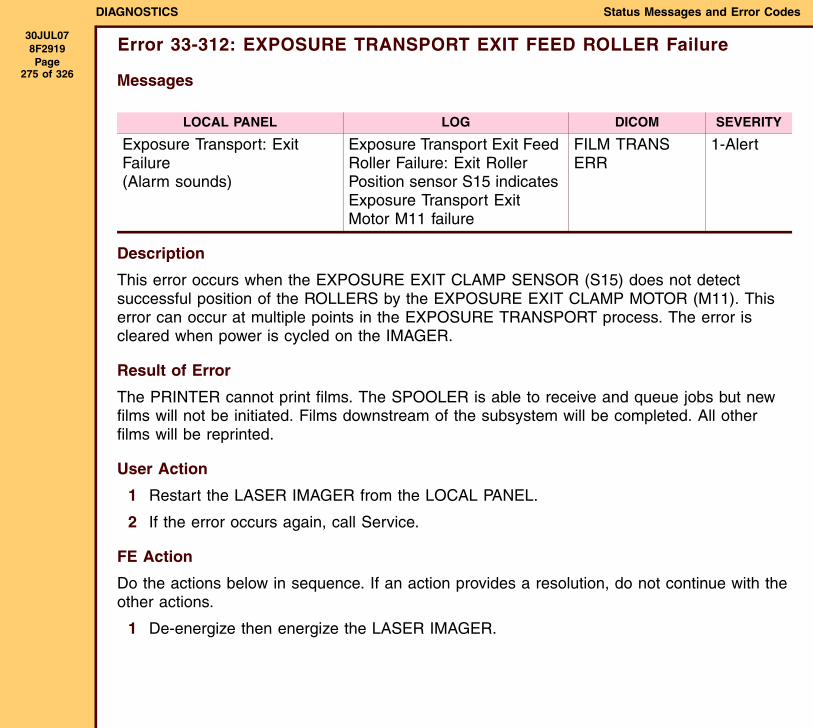
DIAGNOSTICS Status Messages and Error Codes
30JUL078F2919 Page
275 of 326
Error 33-312: EXPOSURE TRANSPORT EXIT FEED ROLLER Failure
Messages
Description
This error occurs when the EXPOSURE EXIT CLAMP SENSOR (S15) does not detect successful position of the ROLLERS by the EXPOSURE EXIT CLAMP MOTOR (M11). This error can occur at multiple points in the EXPOSURE TRANSPORT process. The error is cleared when power is cycled on the IMAGER.
Result of Error
The PRINTER cannot print films. The SPOOLER is able to receive and queue jobs but new films will not be initiated. Films downstream of the subsystem will be completed. All other films will be reprinted.
User Action
1 Restart the LASER IMAGER from the LOCAL PANEL.
2 If the error occurs again, call Service.
FE Action
Do the actions below in sequence. If an action provides a resolution, do not continue with the other actions.
1 De-energize then energize the LASER IMAGER.
LOCAL PANEL LOG DICOM SEVERITY
Exposure Transport: Exit Failure(Alarm sounds)
Exposure Transport Exit Feed Roller Failure: Exit Roller Position sensor S15 indicates Exposure Transport Exit Motor M11 failure
FILM TRANS ERR
1-Alert
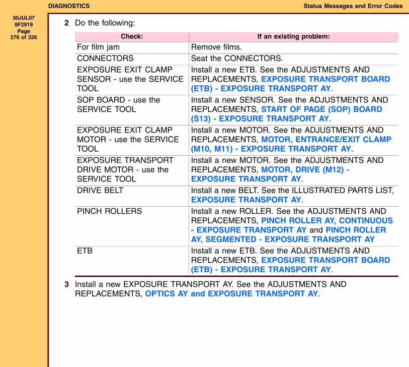
DIAGNOSTICS Status Messages and Error Codes
30JUL078F2919 Page
276 of 326
2 Do the following:
3 Install a new EXPOSURE TRANSPORT AY. See the ADJUSTMENTS AND REPLACEMENTS, OPTICS AY and EXPOSURE TRANSPORT AY.
Check: If an existing problem:
For film jam Remove films.CONNECTORS Seat the CONNECTORS.EXPOSURE EXIT CLAMP SENSOR - use the SERVICE TOOL
Install a new ETB. See the ADJUSTMENTS AND REPLACEMENTS, EXPOSURE TRANSPORT BOARD (ETB) - EXPOSURE TRANSPORT AY.
SOP BOARD - use the SERVICE TOOL
Install a new SENSOR. See the ADJUSTMENTS AND REPLACEMENTS, START OF PAGE (SOP) BOARD (S13) - EXPOSURE TRANSPORT AY.
EXPOSURE EXIT CLAMP MOTOR - use the SERVICE TOOL
Install a new MOTOR. See the ADJUSTMENTS AND REPLACEMENTS, MOTOR, ENTRANCE/EXIT CLAMP (M10, M11) - EXPOSURE TRANSPORT AY.
EXPOSURE TRANSPORT DRIVE MOTOR - use the SERVICE TOOL
Install a new MOTOR. See the ADJUSTMENTS AND REPLACEMENTS, MOTOR, DRIVE (M12) - EXPOSURE TRANSPORT AY.
DRIVE BELT Install a new BELT. See the ILLUSTRATED PARTS LIST, EXPOSURE TRANSPORT AY.
PINCH ROLLERS Install a new ROLLER. See the ADJUSTMENTS AND REPLACEMENTS, PINCH ROLLER AY, CONTINUOUS - EXPOSURE TRANSPORT AY and PINCH ROLLER AY, SEGMENTED - EXPOSURE TRANSPORT AY
ETB Install a new ETB. See the ADJUSTMENTS AND REPLACEMENTS, EXPOSURE TRANSPORT BOARD (ETB) - EXPOSURE TRANSPORT AY.
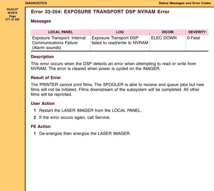
DIAGNOSTICS Status Messages and Error Codes
30JUL078F2919 Page
277 of 326
Error 33-354: EXPOSURE TRANSPORT DSP NVRAM Error
Messages
Description
This error occurs when the DSP detects an error when attempting to read or write from NVRAM. The error is cleared when power is cycled on the IMAGER.
Result of Error
The PRINTER cannot print films. The SPOOLER is able to receive and queue jobs but new films will not be initiated. Films downstream of the subsystem will be completed. All other films will be reprinted.
User Action
1 Restart the LASER IMAGER from the LOCAL PANEL.
2 If the error occurs again, call Service.
FE Action
1 De-energize then energize the LASER IMAGER.
LOCAL PANEL LOG DICOM SEVERITY
Exposure Transport: Internal Communications Failure(Alarm sounds)
Exposure Transport DSP failed to read/write to NVRAM
ELEC DOWN 0-Fatal

DIAGNOSTICS Status Messages and Error Codes
30JUL078F2919 Page
278 of 326
2 Do the following:
3 Install a new EXPOSURE TRANSPORT AY. See the ADJUSTMENTS AND REPLACEMENTS, OPTICS AY and EXPOSURE TRANSPORT AY.
Check: If an existing problem:
CONNECTORS on the PDB and ETB
Seat the CONNECTORS.
ETB Install a new ETB. See the ADJUSTMENTS AND REPLACEMENTS, EXPOSURE TRANSPORT BOARD (ETB) - EXPOSURE TRANSPORT AY.
PDB Install a new PDB. See the ADJUSTMENTS AND REPLACEMENTS, POWER DISTRIBUTION BOARD (PDB).
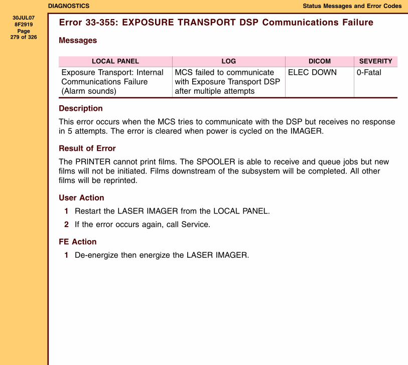
DIAGNOSTICS Status Messages and Error Codes
30JUL078F2919 Page
279 of 326
Error 33-355: EXPOSURE TRANSPORT DSP Communications Failure
Messages
Description
This error occurs when the MCS tries to communicate with the DSP but receives no response in 5 attempts. The error is cleared when power is cycled on the IMAGER.
Result of Error
The PRINTER cannot print films. The SPOOLER is able to receive and queue jobs but new films will not be initiated. Films downstream of the subsystem will be completed. All other films will be reprinted.
User Action
1 Restart the LASER IMAGER from the LOCAL PANEL.
2 If the error occurs again, call Service.
FE Action
1 De-energize then energize the LASER IMAGER.
LOCAL PANEL LOG DICOM SEVERITY
Exposure Transport: Internal Communications Failure(Alarm sounds)
MCS failed to communicate with Exposure Transport DSP after multiple attempts
ELEC DOWN 0-Fatal
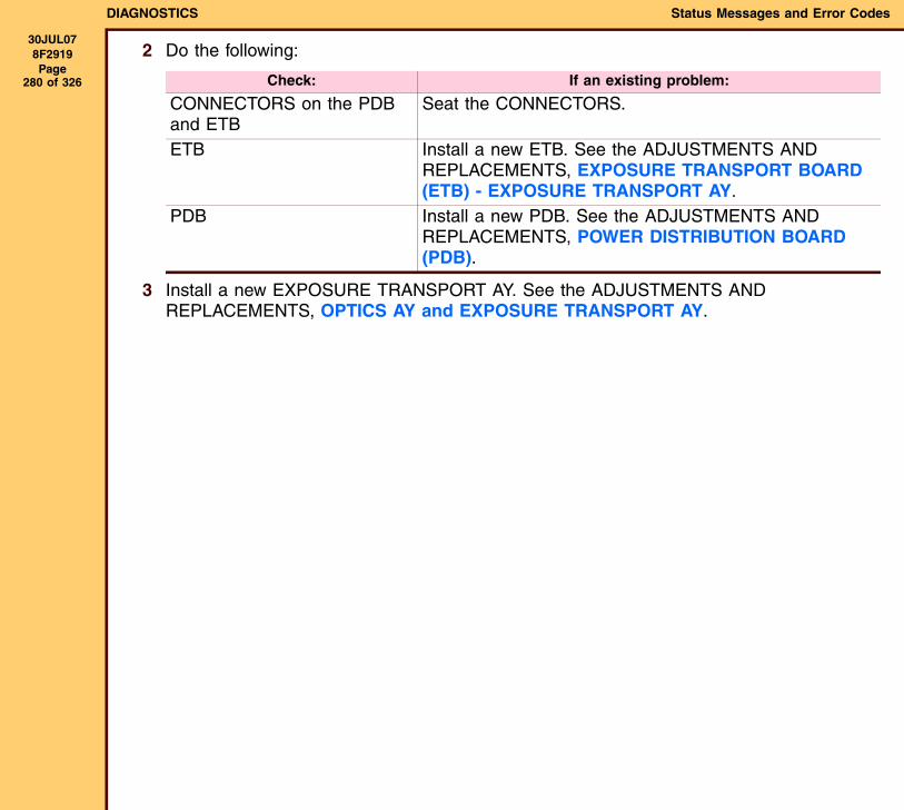
DIAGNOSTICS Status Messages and Error Codes
30JUL078F2919 Page
280 of 326
2 Do the following:
3 Install a new EXPOSURE TRANSPORT AY. See the ADJUSTMENTS AND REPLACEMENTS, OPTICS AY and EXPOSURE TRANSPORT AY.
Check: If an existing problem:
CONNECTORS on the PDB and ETB
Seat the CONNECTORS.
ETB Install a new ETB. See the ADJUSTMENTS AND REPLACEMENTS, EXPOSURE TRANSPORT BOARD (ETB) - EXPOSURE TRANSPORT AY.
PDB Install a new PDB. See the ADJUSTMENTS AND REPLACEMENTS, POWER DISTRIBUTION BOARD (PDB).
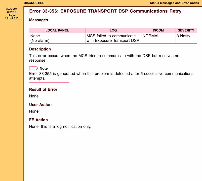
DIAGNOSTICS Status Messages and Error Codes
30JUL078F2919 Page
281 of 326
Error 33-356: EXPOSURE TRANSPORT DSP Communications Retry
Messages
Description
This error occurs when the MCS tries to communicate with the DSP but receives no response.
NoteError 33-355 is generated when this problem is detected after 5 successive communications attempts.
Result of Error
None
User Action
None
FE Action
None, this is a log notification only.
LOCAL PANEL LOG DICOM SEVERITY
None(No alarm)
MCS failed to communicate with Exposure Transport DSP
NORMAL 3-Notify
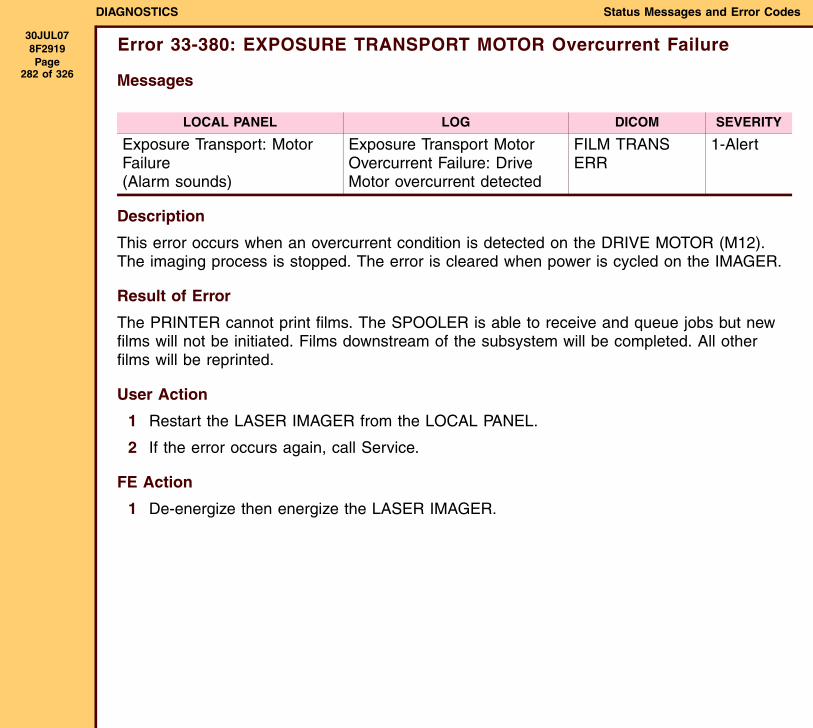
DIAGNOSTICS Status Messages and Error Codes
30JUL078F2919 Page
282 of 326
Error 33-380: EXPOSURE TRANSPORT MOTOR Overcurrent Failure
Messages
Description
This error occurs when an overcurrent condition is detected on the DRIVE MOTOR (M12). The imaging process is stopped. The error is cleared when power is cycled on the IMAGER.
Result of Error
The PRINTER cannot print films. The SPOOLER is able to receive and queue jobs but new films will not be initiated. Films downstream of the subsystem will be completed. All other films will be reprinted.
User Action
1 Restart the LASER IMAGER from the LOCAL PANEL.
2 If the error occurs again, call Service.
FE Action
1 De-energize then energize the LASER IMAGER.
LOCAL PANEL LOG DICOM SEVERITY
Exposure Transport: Motor Failure(Alarm sounds)
Exposure Transport Motor Overcurrent Failure: Drive Motor overcurrent detected
FILM TRANS ERR
1-Alert
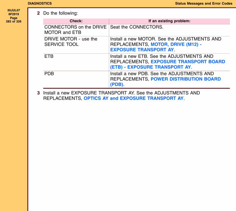
DIAGNOSTICS Status Messages and Error Codes
30JUL078F2919 Page
283 of 326
2 Do the following:
3 Install a new EXPOSURE TRANSPORT AY. See the ADJUSTMENTS AND REPLACEMENTS, OPTICS AY and EXPOSURE TRANSPORT AY.
Check: If an existing problem:
CONNECTORS on the DRIVE MOTOR and ETB
Seat the CONNECTORS.
DRIVE MOTOR - use the SERVICE TOOL
Install a new MOTOR. See the ADJUSTMENTS AND REPLACEMENTS, MOTOR, DRIVE (M12) - EXPOSURE TRANSPORT AY.
ETB Install a new ETB. See the ADJUSTMENTS AND REPLACEMENTS, EXPOSURE TRANSPORT BOARD (ETB) - EXPOSURE TRANSPORT AY.
PDB Install a new PDB. See the ADJUSTMENTS AND REPLACEMENTS, POWER DISTRIBUTION BOARD (PDB).
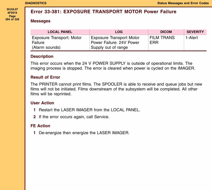
DIAGNOSTICS Status Messages and Error Codes
30JUL078F2919 Page
284 of 326
Error 33-381: EXPOSURE TRANSPORT MOTOR Power Failure
Messages
Description
This error occurs when the 24 V POWER SUPPLY is outside of operational limits. The imaging process is stopped. The error is cleared when power is cycled on the IMAGER.
Result of Error
The PRINTER cannot print films. The SPOOLER is able to receive and queue jobs but new films will not be initiated. Films downstream of the subsystem will be completed. All other films will be reprinted.
User Action
1 Restart the LASER IMAGER from the LOCAL PANEL.
2 If the error occurs again, call Service.
FE Action
1 De-energize then energize the LASER IMAGER.
LOCAL PANEL LOG DICOM SEVERITY
Exposure Transport: Motor Failure(Alarm sounds)
Exposure Transport Motor Power Failure: 24V Power Supply out of range
FILM TRANS ERR
1-Alert

DIAGNOSTICS Status Messages and Error Codes
30JUL078F2919 Page
285 of 326
2 Do the following:
3 Install a new EXPOSURE TRANSPORT AY. See the ADJUSTMENTS AND REPLACEMENTS, OPTICS AY and EXPOSURE TRANSPORT AY.
Check: If an existing problem:
CONNECTORS on the ETB and PDB
Seat the CONNECTORS.
ETB Install a new ETB. See the ADJUSTMENTS AND REPLACEMENTS, EXPOSURE TRANSPORT BOARD (ETB) - EXPOSURE TRANSPORT AY.
PDB Install a new PDB. See the ADJUSTMENTS AND REPLACEMENTS, POWER DISTRIBUTION BOARD (PDB).
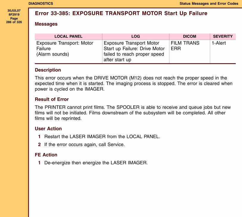
DIAGNOSTICS Status Messages and Error Codes
30JUL078F2919 Page
286 of 326
Error 33-385: EXPOSURE TRANSPORT MOTOR Start Up Failure
Messages
Description
This error occurs when the DRIVE MOTOR (M12) does not reach the proper speed in the expected time when it is started. The imaging process is stopped. The error is cleared when power is cycled on the IMAGER.
Result of Error
The PRINTER cannot print films. The SPOOLER is able to receive and queue jobs but new films will not be initiated. Films downstream of the subsystem will be completed. All other films will be reprinted.
User Action
1 Restart the LASER IMAGER from the LOCAL PANEL.
2 If the error occurs again, call Service.
FE Action
1 De-energize then energize the LASER IMAGER.
LOCAL PANEL LOG DICOM SEVERITY
Exposure Transport: Motor Failure(Alarm sounds)
Exposure Transport Motor Start up Failure: Drive Motor failed to reach proper speed after start up
FILM TRANS ERR
1-Alert

DIAGNOSTICS Status Messages and Error Codes
30JUL078F2919 Page
287 of 326
2 Do the following:
3 Install a new EXPOSURE TRANSPORT AY. See the ADJUSTMENTS AND REPLACEMENTS, OPTICS AY and EXPOSURE TRANSPORT AY.
Check: If an existing problem:
CONNECTORS on the DRIVE MOTOR and ETB
Seat the CONNECTORS.
DRIVE MOTOR - use the SERVICE TOOL
Install a new MOTOR. See the ADJUSTMENTS AND REPLACEMENTS, MOTOR, DRIVE (M12) - EXPOSURE TRANSPORT AY.
ETB Install a new ETB. See the ADJUSTMENTS AND REPLACEMENTS, EXPOSURE TRANSPORT BOARD (ETB) - EXPOSURE TRANSPORT AY.
PDB Install a new PDB. See the ADJUSTMENTS AND REPLACEMENTS, POWER DISTRIBUTION BOARD (PDB).
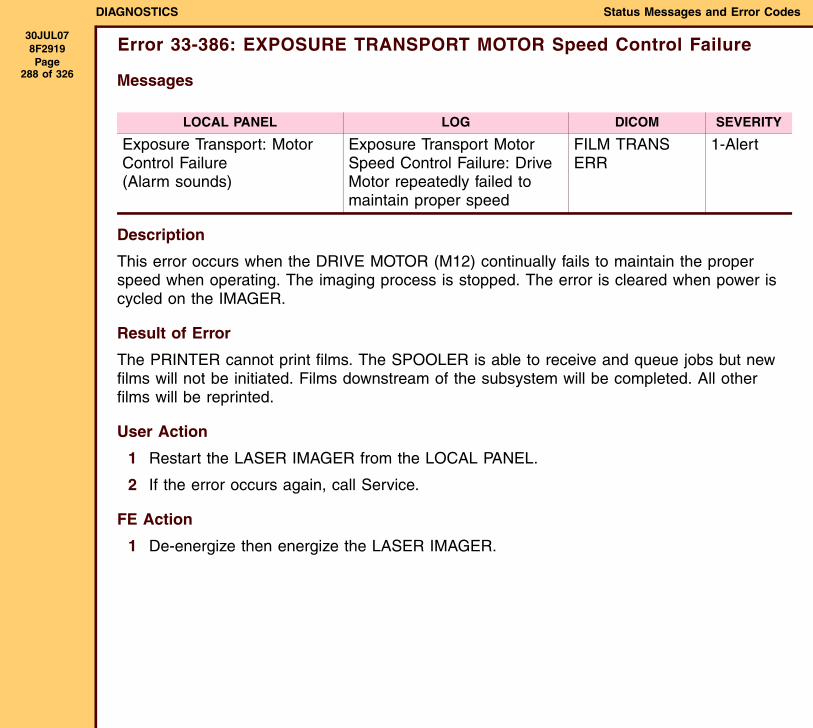
DIAGNOSTICS Status Messages and Error Codes
30JUL078F2919 Page
288 of 326
Error 33-386: EXPOSURE TRANSPORT MOTOR Speed Control Failure
Messages
Description
This error occurs when the DRIVE MOTOR (M12) continually fails to maintain the proper speed when operating. The imaging process is stopped. The error is cleared when power is cycled on the IMAGER.
Result of Error
The PRINTER cannot print films. The SPOOLER is able to receive and queue jobs but new films will not be initiated. Films downstream of the subsystem will be completed. All other films will be reprinted.
User Action
1 Restart the LASER IMAGER from the LOCAL PANEL.
2 If the error occurs again, call Service.
FE Action
1 De-energize then energize the LASER IMAGER.
LOCAL PANEL LOG DICOM SEVERITY
Exposure Transport: Motor Control Failure(Alarm sounds)
Exposure Transport Motor Speed Control Failure: Drive Motor repeatedly failed to maintain proper speed
FILM TRANS ERR
1-Alert

DIAGNOSTICS Status Messages and Error Codes
30JUL078F2919 Page
289 of 326
2 Do the following:
3 Install a new EXPOSURE TRANSPORT AY. See the ADJUSTMENTS AND REPLACEMENTS, OPTICS AY and EXPOSURE TRANSPORT AY.
Check: If an existing problem:
CONNECTORS on the DRIVE MOTOR and ETB
Seat the CONNECTORS.
DRIVE MOTOR - use the SERVICE TOOL
Install a new MOTOR. See the ADJUSTMENTS AND REPLACEMENTS, MOTOR, DRIVE (M12) - EXPOSURE TRANSPORT AY.
ETB Install a new ETB. See the ADJUSTMENTS AND REPLACEMENTS, EXPOSURE TRANSPORT BOARD (ETB) - EXPOSURE TRANSPORT AY.
PDB Install a new PDB. See the ADJUSTMENTS AND REPLACEMENTS, POWER DISTRIBUTION BOARD (PDB).
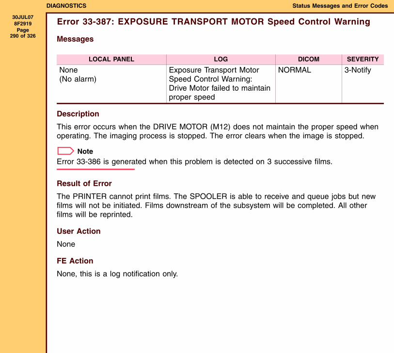
DIAGNOSTICS Status Messages and Error Codes
30JUL078F2919 Page
290 of 326
Error 33-387: EXPOSURE TRANSPORT MOTOR Speed Control Warning
Messages
Description
This error occurs when the DRIVE MOTOR (M12) does not maintain the proper speed when operating. The imaging process is stopped. The error clears when the image is stopped.
NoteError 33-386 is generated when this problem is detected on 3 successive films.
Result of Error
The PRINTER cannot print films. The SPOOLER is able to receive and queue jobs but new films will not be initiated. Films downstream of the subsystem will be completed. All other films will be reprinted.
User Action
None
FE Action
None, this is a log notification only.
LOCAL PANEL LOG DICOM SEVERITY
None(No alarm)
Exposure Transport Motor Speed Control Warning: Drive Motor failed to maintain proper speed
NORMAL 3-Notify
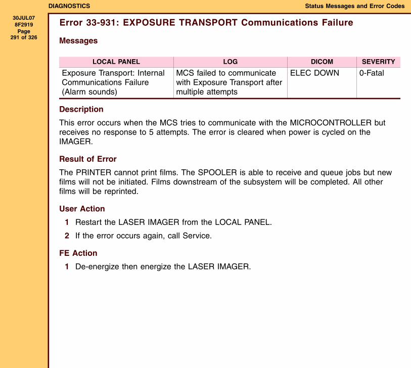
DIAGNOSTICS Status Messages and Error Codes
30JUL078F2919 Page
291 of 326
Error 33-931: EXPOSURE TRANSPORT Communications Failure
Messages
Description
This error occurs when the MCS tries to communicate with the MICROCONTROLLER but receives no response to 5 attempts. The error is cleared when power is cycled on the IMAGER.
Result of Error
The PRINTER cannot print films. The SPOOLER is able to receive and queue jobs but new films will not be initiated. Films downstream of the subsystem will be completed. All other films will be reprinted.
User Action
1 Restart the LASER IMAGER from the LOCAL PANEL.
2 If the error occurs again, call Service.
FE Action
1 De-energize then energize the LASER IMAGER.
LOCAL PANEL LOG DICOM SEVERITY
Exposure Transport: Internal Communications Failure(Alarm sounds)
MCS failed to communicate with Exposure Transport after multiple attempts
ELEC DOWN 0-Fatal

DIAGNOSTICS Status Messages and Error Codes
30JUL078F2919 Page
292 of 326
2 Do the following:
3 Install a new EXPOSURE TRANSPORT AY. See the ADJUSTMENTS AND REPLACEMENTS, OPTICS AY and EXPOSURE TRANSPORT AY.
Check: If an existing problem:
CONNECTORS on the PDB and ETB
Seat the CONNECTORS.
ETB Install a new ETB. See the ADJUSTMENTS AND REPLACEMENTS, EXPOSURE TRANSPORT BOARD (ETB) - EXPOSURE TRANSPORT AY.
PDB Install a new PDB. See the ADJUSTMENTS AND REPLACEMENTS, POWER DISTRIBUTION BOARD (PDB).
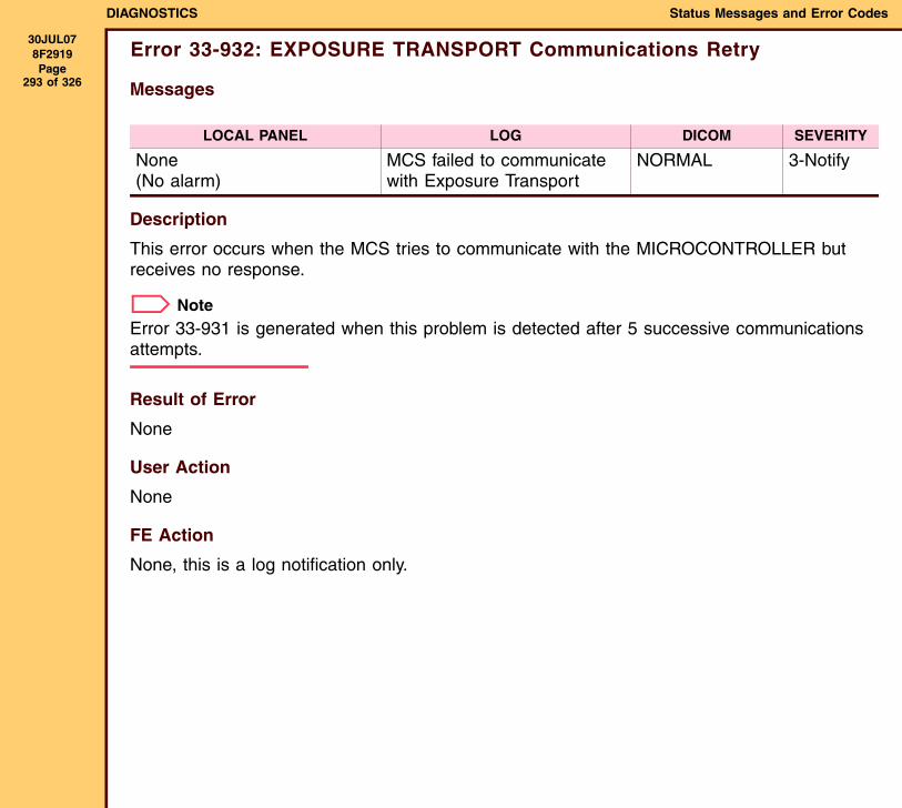
DIAGNOSTICS Status Messages and Error Codes
30JUL078F2919 Page
293 of 326
Error 33-932: EXPOSURE TRANSPORT Communications Retry
Messages
Description
This error occurs when the MCS tries to communicate with the MICROCONTROLLER but receives no response.
NoteError 33-931 is generated when this problem is detected after 5 successive communications attempts.
Result of Error
None
User Action
None
FE Action
None, this is a log notification only.
LOCAL PANEL LOG DICOM SEVERITY
None(No alarm)
MCS failed to communicate with Exposure Transport
NORMAL 3-Notify
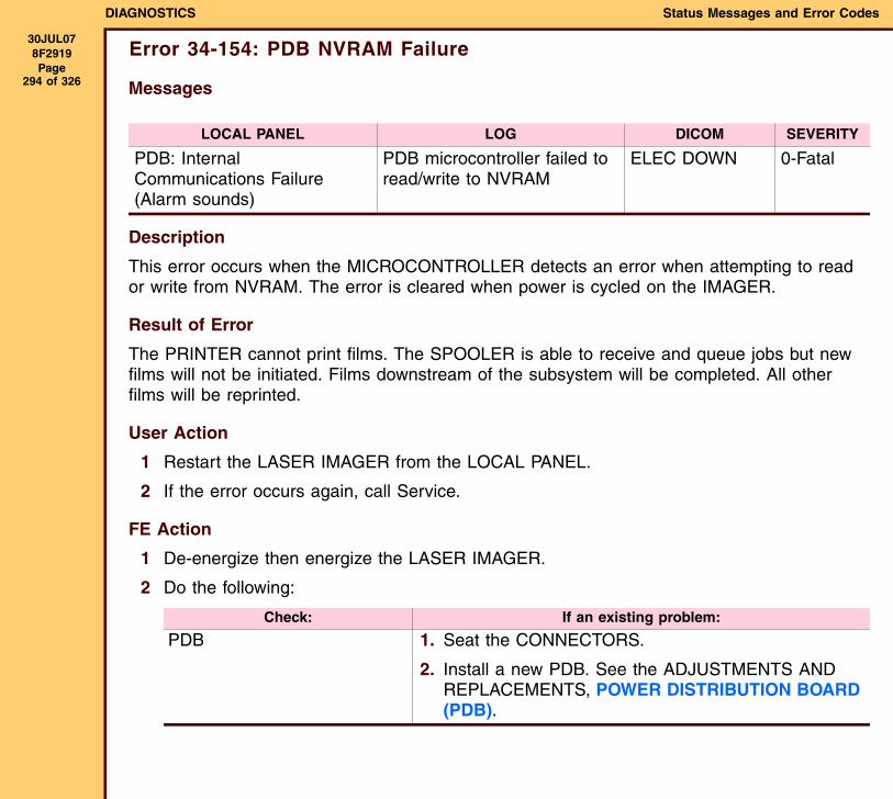
DIAGNOSTICS Status Messages and Error Codes
30JUL078F2919 Page
294 of 326
Error 34-154: PDB NVRAM Failure
Messages
Description
This error occurs when the MICROCONTROLLER detects an error when attempting to read or write from NVRAM. The error is cleared when power is cycled on the IMAGER.
Result of Error
The PRINTER cannot print films. The SPOOLER is able to receive and queue jobs but new films will not be initiated. Films downstream of the subsystem will be completed. All other films will be reprinted.
User Action
1 Restart the LASER IMAGER from the LOCAL PANEL.
2 If the error occurs again, call Service.
FE Action
1 De-energize then energize the LASER IMAGER.
2 Do the following:
LOCAL PANEL LOG DICOM SEVERITY
PDB: Internal Communications Failure(Alarm sounds)
PDB microcontroller failed to read/write to NVRAM
ELEC DOWN 0-Fatal
Check: If an existing problem:
PDB 1. Seat the CONNECTORS.
2. Install a new PDB. See the ADJUSTMENTS AND REPLACEMENTS, POWER DISTRIBUTION BOARD (PDB).
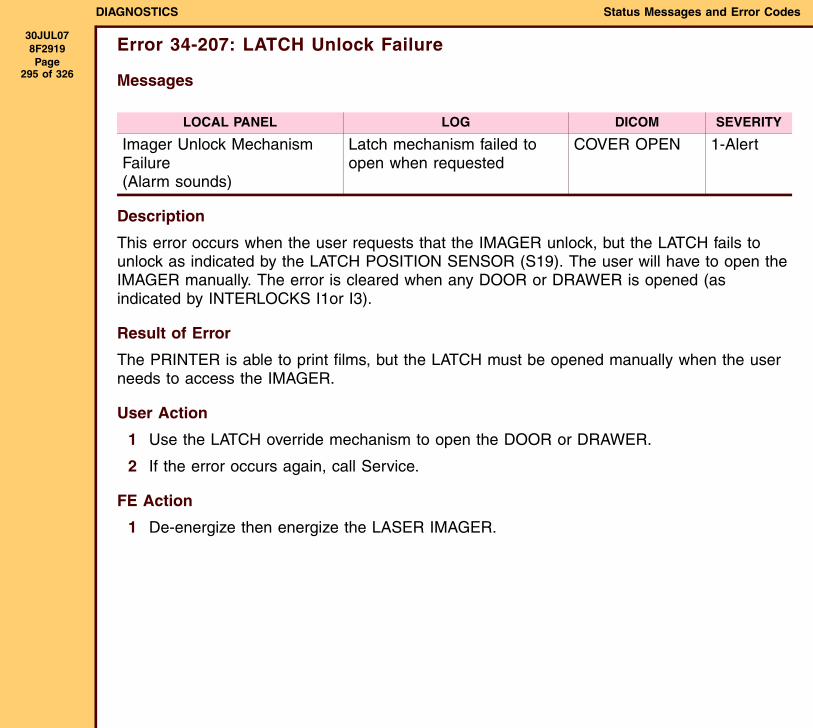
DIAGNOSTICS Status Messages and Error Codes
30JUL078F2919 Page
295 of 326
Error 34-207: LATCH Unlock Failure
Messages
Description
This error occurs when the user requests that the IMAGER unlock, but the LATCH fails to unlock as indicated by the LATCH POSITION SENSOR (S19). The user will have to open the IMAGER manually. The error is cleared when any DOOR or DRAWER is opened (as indicated by INTERLOCKS I1or I3).
Result of Error
The PRINTER is able to print films, but the LATCH must be opened manually when the user needs to access the IMAGER.
User Action
1 Use the LATCH override mechanism to open the DOOR or DRAWER.
2 If the error occurs again, call Service.
FE Action
1 De-energize then energize the LASER IMAGER.
LOCAL PANEL LOG DICOM SEVERITY
Imager Unlock Mechanism Failure(Alarm sounds)
Latch mechanism failed to open when requested
COVER OPEN 1-Alert
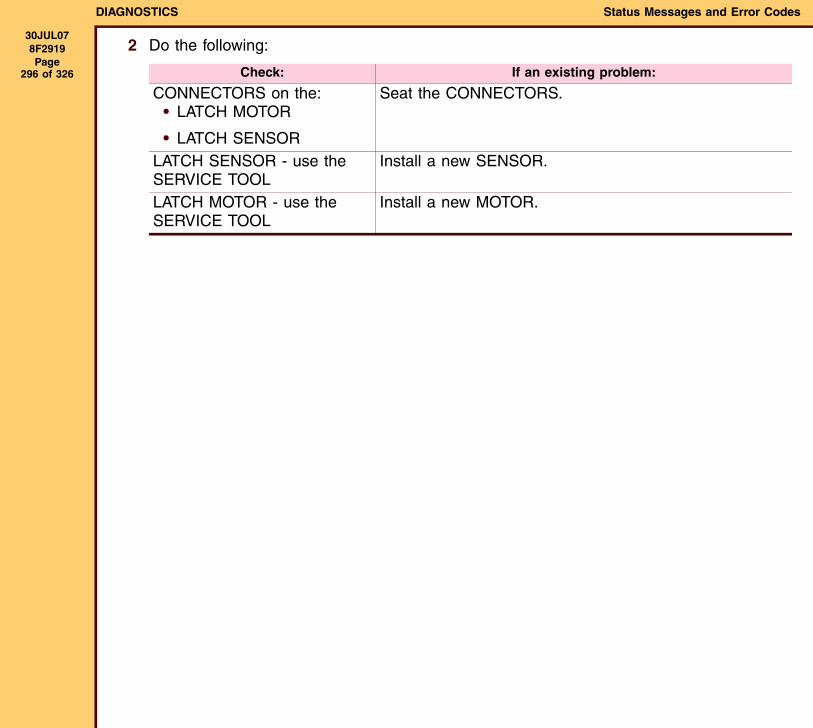
DIAGNOSTICS Status Messages and Error Codes
30JUL078F2919 Page
296 of 326
2 Do the following:
Check: If an existing problem:
CONNECTORS on the:• LATCH MOTOR
• LATCH SENSOR
Seat the CONNECTORS.
LATCH SENSOR - use the SERVICE TOOL
Install a new SENSOR.
LATCH MOTOR - use the SERVICE TOOL
Install a new MOTOR.
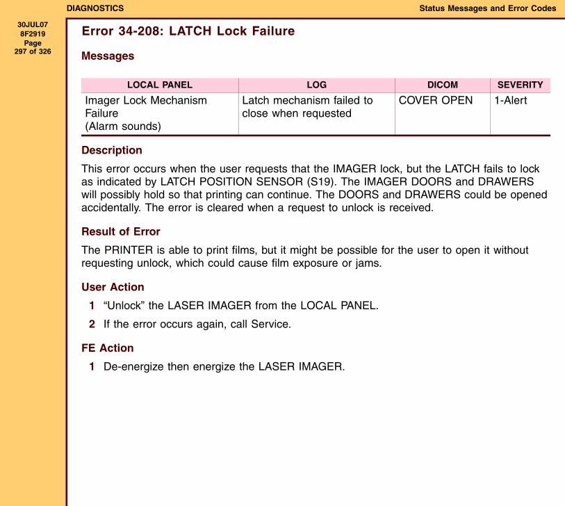
DIAGNOSTICS Status Messages and Error Codes
30JUL078F2919 Page
297 of 326
Error 34-208: LATCH Lock Failure
Messages
Description
This error occurs when the user requests that the IMAGER lock, but the LATCH fails to lock as indicated by LATCH POSITION SENSOR (S19). The IMAGER DOORS and DRAWERS will possibly hold so that printing can continue. The DOORS and DRAWERS could be opened accidentally. The error is cleared when a request to unlock is received.
Result of Error
The PRINTER is able to print films, but it might be possible for the user to open it without requesting unlock, which could cause film exposure or jams.
User Action
1 “Unlock” the LASER IMAGER from the LOCAL PANEL.
2 If the error occurs again, call Service.
FE Action
1 De-energize then energize the LASER IMAGER.
LOCAL PANEL LOG DICOM SEVERITY
Imager Lock Mechanism Failure(Alarm sounds)
Latch mechanism failed to close when requested
COVER OPEN 1-Alert
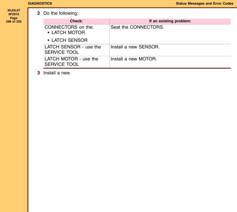
DIAGNOSTICS Status Messages and Error Codes
30JUL078F2919 Page
298 of 326
2 Do the following:
3 Install a new.
Check: If an existing problem:
CONNECTORS on the:• LATCH MOTOR
• LATCH SENSOR
Seat the CONNECTORS.
LATCH SENSOR - use the SERVICE TOOL
Install a new SENSOR.
LATCH MOTOR - use the SERVICE TOOL
Install a new MOTOR.
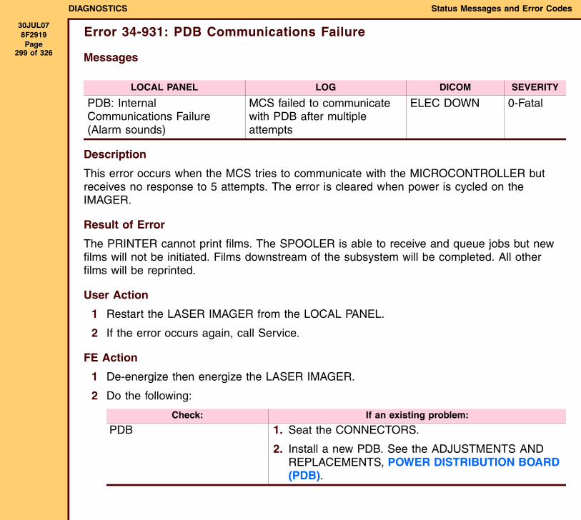
DIAGNOSTICS Status Messages and Error Codes
30JUL078F2919 Page
299 of 326
Error 34-931: PDB Communications Failure
Messages
Description
This error occurs when the MCS tries to communicate with the MICROCONTROLLER but receives no response to 5 attempts. The error is cleared when power is cycled on the IMAGER.
Result of Error
The PRINTER cannot print films. The SPOOLER is able to receive and queue jobs but new films will not be initiated. Films downstream of the subsystem will be completed. All other films will be reprinted.
User Action
1 Restart the LASER IMAGER from the LOCAL PANEL.
2 If the error occurs again, call Service.
FE Action
1 De-energize then energize the LASER IMAGER.
2 Do the following:
LOCAL PANEL LOG DICOM SEVERITY
PDB: Internal Communications Failure(Alarm sounds)
MCS failed to communicate with PDB after multiple attempts
ELEC DOWN 0-Fatal
Check: If an existing problem:
PDB 1. Seat the CONNECTORS.
2. Install a new PDB. See the ADJUSTMENTS AND REPLACEMENTS, POWER DISTRIBUTION BOARD (PDB).
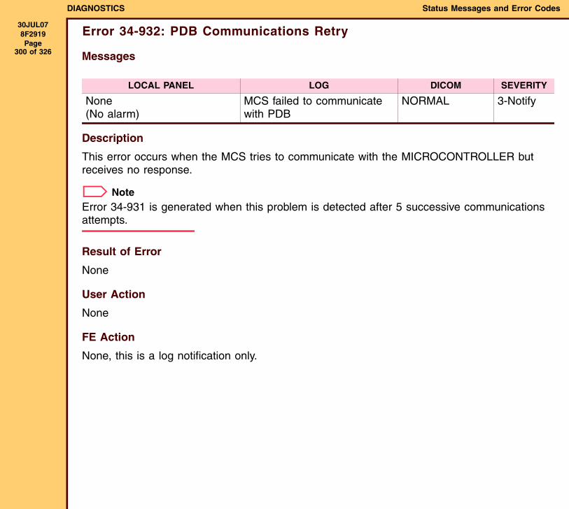
DIAGNOSTICS Status Messages and Error Codes
30JUL078F2919 Page
300 of 326
Error 34-932: PDB Communications Retry
Messages
Description
This error occurs when the MCS tries to communicate with the MICROCONTROLLER but receives no response.
NoteError 34-931 is generated when this problem is detected after 5 successive communications attempts.
Result of Error
None
User Action
None
FE Action
None, this is a log notification only.
LOCAL PANEL LOG DICOM SEVERITY
None(No alarm)
MCS failed to communicate with PDB
NORMAL 3-Notify
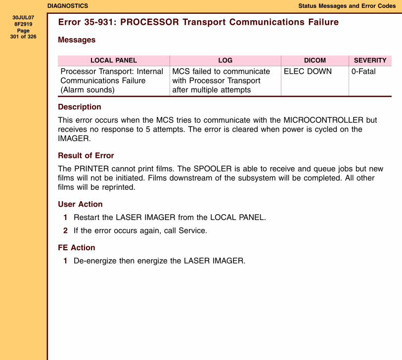
DIAGNOSTICS Status Messages and Error Codes
30JUL078F2919 Page
301 of 326
Error 35-931: PROCESSOR Transport Communications Failure
Messages
Description
This error occurs when the MCS tries to communicate with the MICROCONTROLLER but receives no response to 5 attempts. The error is cleared when power is cycled on the IMAGER.
Result of Error
The PRINTER cannot print films. The SPOOLER is able to receive and queue jobs but new films will not be initiated. Films downstream of the subsystem will be completed. All other films will be reprinted.
User Action
1 Restart the LASER IMAGER from the LOCAL PANEL.
2 If the error occurs again, call Service.
FE Action
1 De-energize then energize the LASER IMAGER.
LOCAL PANEL LOG DICOM SEVERITY
Processor Transport: Internal Communications Failure(Alarm sounds)
MCS failed to communicate with Processor Transport after multiple attempts
ELEC DOWN 0-Fatal
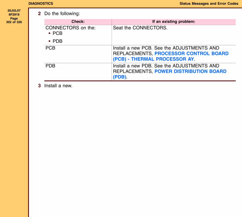
DIAGNOSTICS Status Messages and Error Codes
30JUL078F2919 Page
302 of 326
2 Do the following:
3 Install a new.
Check: If an existing problem:
CONNECTORS on the:• PCB
• PDB
Seat the CONNECTORS.
PCB Install a new PCB. See the ADJUSTMENTS AND REPLACEMENTS, PROCESSOR CONTROL BOARD (PCB) - THERMAL PROCESSOR AY.
PDB Install a new PDB. See the ADJUSTMENTS AND REPLACEMENTS, POWER DISTRIBUTION BOARD (PDB).
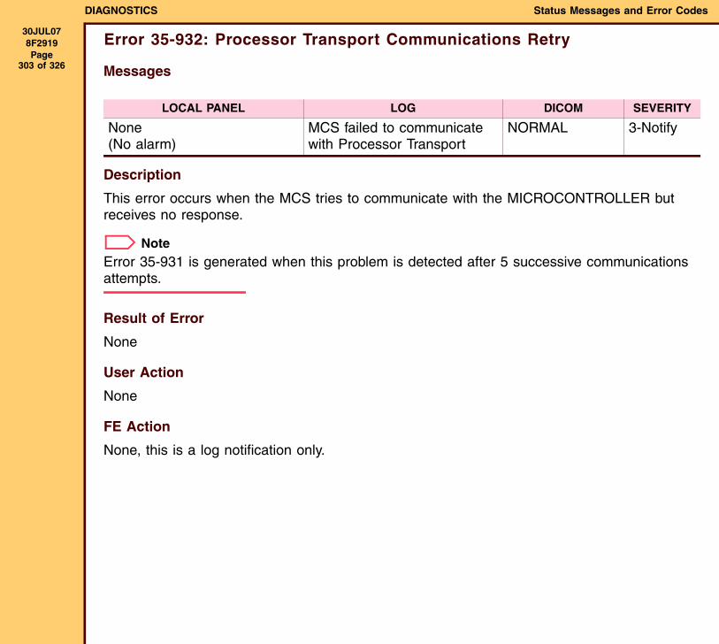
DIAGNOSTICS Status Messages and Error Codes
30JUL078F2919 Page
303 of 326
Error 35-932: Processor Transport Communications Retry
Messages
Description
This error occurs when the MCS tries to communicate with the MICROCONTROLLER but receives no response.
NoteError 35-931 is generated when this problem is detected after 5 successive communications attempts.
Result of Error
None
User Action
None
FE Action
None, this is a log notification only.
LOCAL PANEL LOG DICOM SEVERITY
None(No alarm)
MCS failed to communicate with Processor Transport
NORMAL 3-Notify
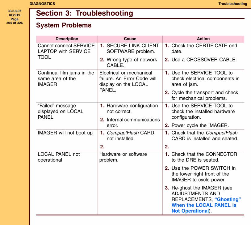
DIAGNOSTICS Troubleshooting
30JUL078F2919 Page
304 of 326
Section 3: Troubleshooting
System Problems
Description Cause Action
Cannot connect SERVICE LAPTOP with SERVICE TOOL
1. SECURE LINK CLIENT SOFTWARE problem.
2. Wrong type of network CABLE.
1. Check the CERTIFICATE end date.
2. Use a CROSSOVER CABLE.
Continual film jams in the same area of the IMAGER
Electrical or mechanical failure. An Error Code will display on the LOCAL PANEL.
1. Use the SERVICE TOOL to check electrical components in area of jam.
2. Cycle the transport and check for mechanical problems.
“Failed” message displayed on LOCAL PANEL
1. Hardware configuration not correct.
2. Internal communications error.
1. Use the SERVICE TOOL to check the installed hardware configuration.
2. Power cycle the IMAGER.
IMAGER will not boot up 1. CompactFlash CARD not installed.
2.
1. Check that the CompactFlash CARD is installed and seated.
2.
LOCAL PANEL not operational
Hardware or software problem.
1. Check that the CONNECTOR to the DRE is seated.
2. Use the POWER SWITCH in the lower right front of the IMAGER to cycle power.
3. Re-ghost the IMAGER (see ADJUSTMENTS AND REPLACEMENTS, “Ghosting” When the LOCAL PANEL is Not Operational).
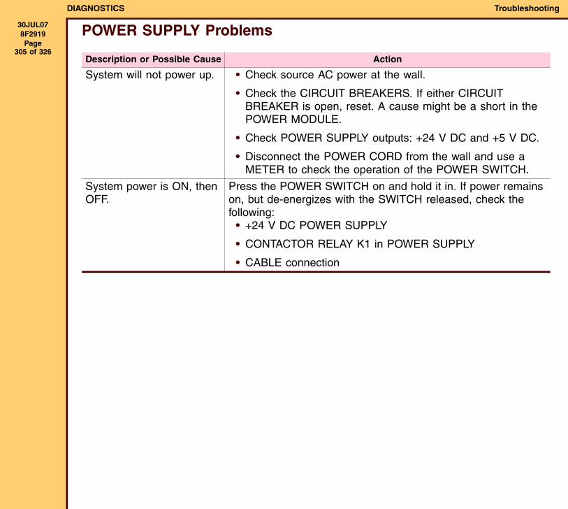
DIAGNOSTICS Troubleshooting
30JUL078F2919 Page
305 of 326
POWER SUPPLY Problems
Description or Possible Cause Action
System will not power up. • Check source AC power at the wall.
• Check the CIRCUIT BREAKERS. If either CIRCUIT BREAKER is open, reset. A cause might be a short in the POWER MODULE.
• Check POWER SUPPLY outputs: +24 V DC and +5 V DC.
• Disconnect the POWER CORD from the wall and use a METER to check the operation of the POWER SWITCH.
System power is ON, then OFF.
Press the POWER SWITCH on and hold it in. If power remains on, but de-energizes with the SWITCH released, check the following:
• +24 V DC POWER SUPPLY
• CONTACTOR RELAY K1 in POWER SUPPLY
• CABLE connection
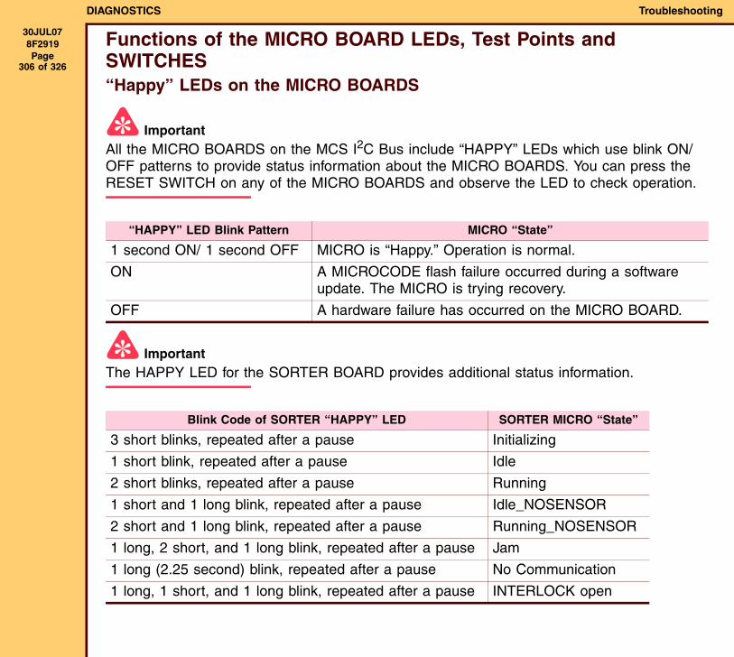
DIAGNOSTICS Troubleshooting
30JUL078F2919 Page
306 of 326
Functions of the MICRO BOARD LEDs, Test Points and SWITCHES“Happy” LEDs on the MICRO BOARDS
ImportantAll the MICRO BOARDS on the MCS I2C Bus include “HAPPY” LEDs which use blink ON/OFF patterns to provide status information about the MICRO BOARDS. You can press the RESET SWITCH on any of the MICRO BOARDS and observe the LED to check operation.
ImportantThe HAPPY LED for the SORTER BOARD provides additional status information.
“HAPPY” LED Blink Pattern MICRO “State”
1 second ON/ 1 second OFF MICRO is “Happy.” Operation is normal.
ON A MICROCODE flash failure occurred during a software update. The MICRO is trying recovery.
OFF A hardware failure has occurred on the MICRO BOARD.
Blink Code of SORTER “HAPPY” LED SORTER MICRO “State”
3 short blinks, repeated after a pause Initializing
1 short blink, repeated after a pause Idle
2 short blinks, repeated after a pause Running
1 short and 1 long blink, repeated after a pause Idle_NOSENSOR
2 short and 1 long blink, repeated after a pause Running_NOSENSOR
1 long, 2 short, and 1 long blink, repeated after a pause Jam
1 long (2.25 second) blink, repeated after a pause No Communication
1 long, 1 short, and 1 long blink, repeated after a pause INTERLOCK open
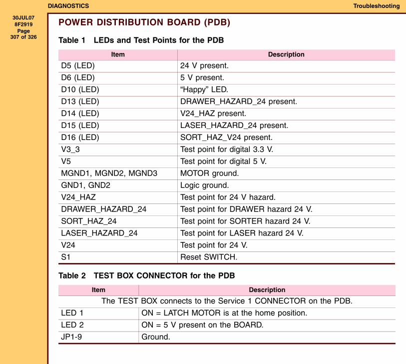
DIAGNOSTICS Troubleshooting
30JUL078F2919 Page
307 of 326
POWER DISTRIBUTION BOARD (PDB)
Table 1 LEDs and Test Points for the PDB
Table 2 TEST BOX CONNECTOR for the PDB
Item Description
D5 (LED) 24 V present.
D6 (LED) 5 V present.
D10 (LED) “Happy” LED.
D13 (LED) DRAWER_HAZARD_24 present.
D14 (LED) V24_HAZ present.
D15 (LED) LASER_HAZARD_24 present.
D16 (LED) SORT_HAZ_V24 present.
V3_3 Test point for digital 3.3 V.
V5 Test point for digital 5 V.
MGND1, MGND2, MGND3 MOTOR ground.
GND1, GND2 Logic ground.
V24_HAZ Test point for 24 V hazard.
DRAWER_HAZARD_24 Test point for DRAWER hazard 24 V.
SORT_HAZ_24 Test point for SORTER hazard 24 V.
LASER_HAZARD_24 Test point for LASER hazard 24 V.
V24 Test point for 24 V.
S1 Reset SWITCH.
Item Description
The TEST BOX connects to the Service 1 CONNECTOR on the PDB.
LED 1 ON = LATCH MOTOR is at the home position.
LED 2 ON = 5 V present on the BOARD.
JP1-9 Ground.
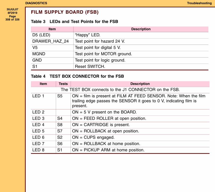
DIAGNOSTICS Troubleshooting
30JUL078F2919 Page
308 of 326
FILM SUPPLY BOARD (FSB)
Table 3 LEDs and Test Points for the FSB
Table 4 TEST BOX CONNECTOR for the FSB
Item Description
D5 (LED) “Happy” LED.
DRAWER_HAZ_24 Test point for hazard 24 V.
V5 Test point for digital 5 V.
MGND Test point for MOTOR ground.
GND Test point for logic ground.
S1 Reset SWITCH.
Item Tests Description
The TEST BOX connects to the J1 CONNECTOR on the FSB.
LED 1 S5 ON = film is present at FILM AT FEED SENSOR. Note: When the film trailing edge passes the SENSOR it goes to 0 V, indicating film is present.
LED 2 ON = 5 V present on the BOARD.
LED 3 S4 ON = FEED ROLLER at open position.
LED 4 S8 ON = CARTRIDGE is present.
LED 5 S7 ON = ROLLBACK at open position.
LED 6 S2 ON = CUPS engaged.
LED 7 S6 ON = ROLLBACK at home position.
LED 8 S1 ON = PICKUP ARM at home position.
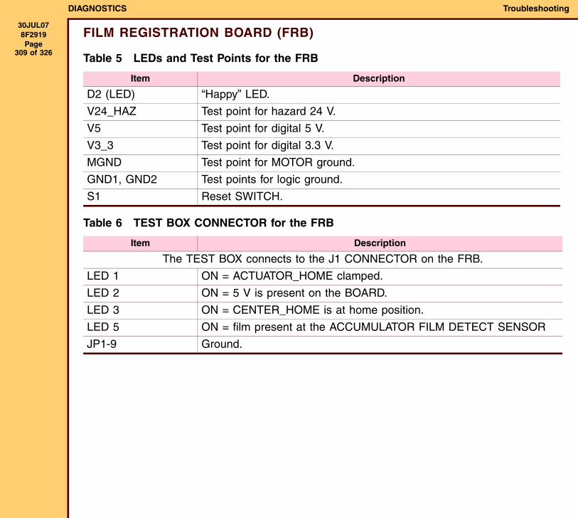
DIAGNOSTICS Troubleshooting
30JUL078F2919 Page
309 of 326
FILM REGISTRATION BOARD (FRB)
Table 5 LEDs and Test Points for the FRB
Table 6 TEST BOX CONNECTOR for the FRB
Item Description
D2 (LED) “Happy” LED.
V24_HAZ Test point for hazard 24 V.
V5 Test point for digital 5 V.
V3_3 Test point for digital 3.3 V.
MGND Test point for MOTOR ground.
GND1, GND2 Test points for logic ground.
S1 Reset SWITCH.
Item Description
The TEST BOX connects to the J1 CONNECTOR on the FRB.
LED 1 ON = ACTUATOR_HOME clamped.
LED 2 ON = 5 V is present on the BOARD.
LED 3 ON = CENTER_HOME is at home position.
LED 5 ON = film present at the ACCUMULATOR FILM DETECT SENSOR
JP1-9 Ground.
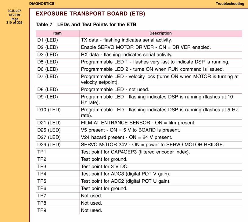
DIAGNOSTICS Troubleshooting
30JUL078F2919 Page
310 of 326
EXPOSURE TRANSPORT BOARD (ETB)
Table 7 LEDs and Test Points for the ETB
Item Description
D1 (LED) TX data - flashing indicates serial activity.
D2 (LED) Enable SERVO MOTOR DRIVER - ON = DRIVER enabled.
D3 (LED) RX data - flashing indicates serial activity.
D5 (LED) Programmable LED 1 - flashes very fast to indicate DSP is running.
D6 (LED) Programmable LED 2 - turns ON when RUN command is issued.
D7 (LED) Programmable LED - velocity lock (turns ON when MOTOR is turning at velocity setpoint).
D8 (LED) Programmable LED - not used.
D9 (LED) Programmable LED - flashing indicates DSP is running (flashes at 10 Hz rate).
D10 (LED) Programmable LED - flashing indicates DSP is running (flashes at 5 Hz rate).
D21 (LED) FILM AT ENTRANCE SENSOR - ON = film present.
D25 (LED) V5 present - ON = 5 V to BOARD is present.
D27 (LED) V24 hazard present - ON = 24 V present.
D29 (LED) SERVO MOTOR 24V - ON = power to SERVO MOTOR BRIDGE.
TP1 Test point for CAP4QEP3 (filtered encoder index).
TP2 Test point for ground.
TP3 Test point for 3 V DC.
TP4 Test point for ADC3 (digital POT V gain).
TP5 Test point for ADC2 (digital POT U gain).
TP6 Test point for ground.
TP7 Not used.
TP8 Not used.
TP9 Not used.
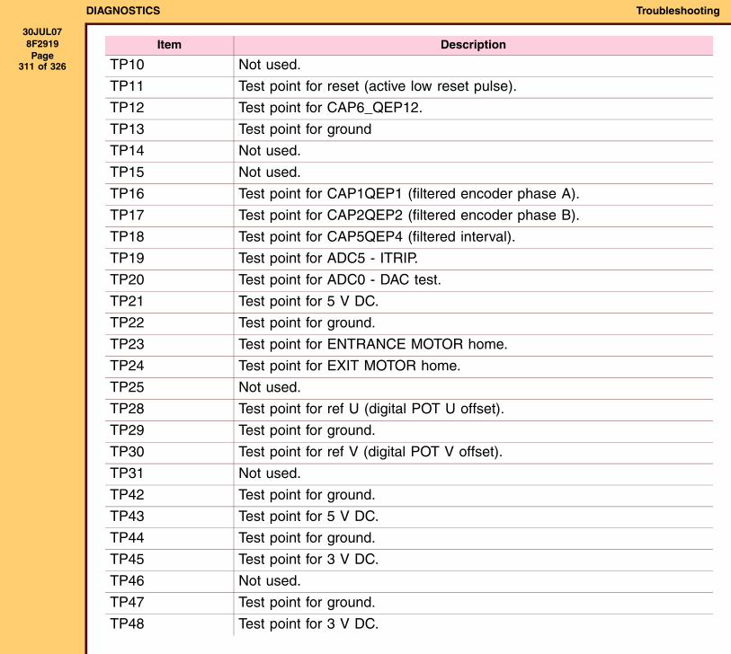
DIAGNOSTICS Troubleshooting
30JUL078F2919 Page
311 of 326 TP10 Not used.
TP11 Test point for reset (active low reset pulse).
TP12 Test point for CAP6_QEP12.
TP13 Test point for ground
TP14 Not used.
TP15 Not used.
TP16 Test point for CAP1QEP1 (filtered encoder phase A).
TP17 Test point for CAP2QEP2 (filtered encoder phase B).
TP18 Test point for CAP5QEP4 (filtered interval).
TP19 Test point for ADC5 - ITRIP.
TP20 Test point for ADC0 - DAC test.
TP21 Test point for 5 V DC.
TP22 Test point for ground.
TP23 Test point for ENTRANCE MOTOR home.
TP24 Test point for EXIT MOTOR home.
TP25 Not used.
TP28 Test point for ref U (digital POT U offset).
TP29 Test point for ground.
TP30 Test point for ref V (digital POT V offset).
TP31 Not used.
TP42 Test point for ground.
TP43 Test point for 5 V DC.
TP44 Test point for ground.
TP45 Test point for 3 V DC.
TP46 Not used.
TP47 Test point for ground.
TP48 Test point for 3 V DC.
Item Description
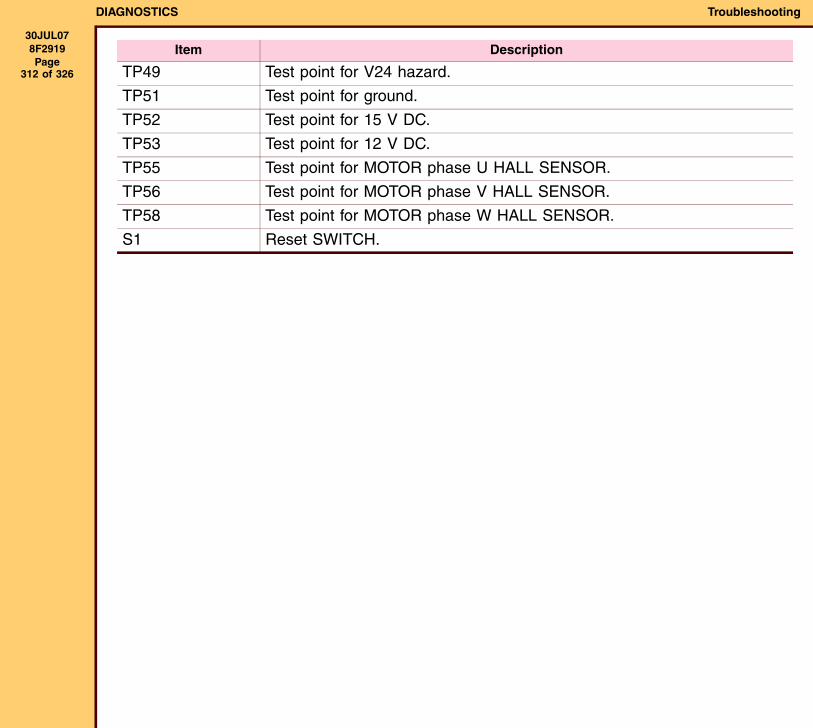
DIAGNOSTICS Troubleshooting
30JUL078F2919 Page
312 of 326 TP49 Test point for V24 hazard.
TP51 Test point for ground.
TP52 Test point for 15 V DC.
TP53 Test point for 12 V DC.
TP55 Test point for MOTOR phase U HALL SENSOR.
TP56 Test point for MOTOR phase V HALL SENSOR.
TP58 Test point for MOTOR phase W HALL SENSOR.
S1 Reset SWITCH.
Item Description
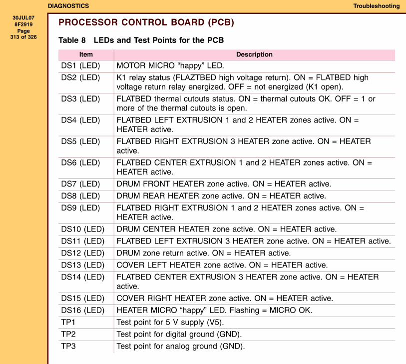
DIAGNOSTICS Troubleshooting
30JUL078F2919 Page
313 of 326
PROCESSOR CONTROL BOARD (PCB)
Table 8 LEDs and Test Points for the PCB
Item Description
DS1 (LED) MOTOR MICRO “happy” LED.
DS2 (LED) K1 relay status (FLAZTBED high voltage return). ON = FLATBED high voltage return relay energized. OFF = not energized (K1 open).
DS3 (LED) FLATBED thermal cutouts status. ON = thermal cutouts OK. OFF = 1 or more of the thermal cutouts is open.
DS4 (LED) FLATBED LEFT EXTRUSION 1 and 2 HEATER zones active. ON = HEATER active.
DS5 (LED) FLATBED RIGHT EXTRUSION 3 HEATER zone active. ON = HEATER active.
DS6 (LED) FLATBED CENTER EXTRUSION 1 and 2 HEATER zones active. ON = HEATER active.
DS7 (LED) DRUM FRONT HEATER zone active. ON = HEATER active.
DS8 (LED) DRUM REAR HEATER zone active. ON = HEATER active.
DS9 (LED) FLATBED RIGHT EXTRUSION 1 and 2 HEATER zones active. ON = HEATER active.
DS10 (LED) DRUM CENTER HEATER zone active. ON = HEATER active.
DS11 (LED) FLATBED LEFT EXTRUSION 3 HEATER zone active. ON = HEATER active.
DS12 (LED) DRUM zone return active. ON = HEATER active.
DS13 (LED) COVER LEFT HEATER zone active. ON = HEATER active.
DS14 (LED) FLATBED CENTER EXTRUSION 3 HEATER zone active. ON = HEATER active.
DS15 (LED) COVER RIGHT HEATER zone active. ON = HEATER active.
DS16 (LED) HEATER MICRO “happy” LED. Flashing = MICRO OK.
TP1 Test point for 5 V supply (V5).
TP2 Test point for digital ground (GND).
TP3 Test point for analog ground (GND).
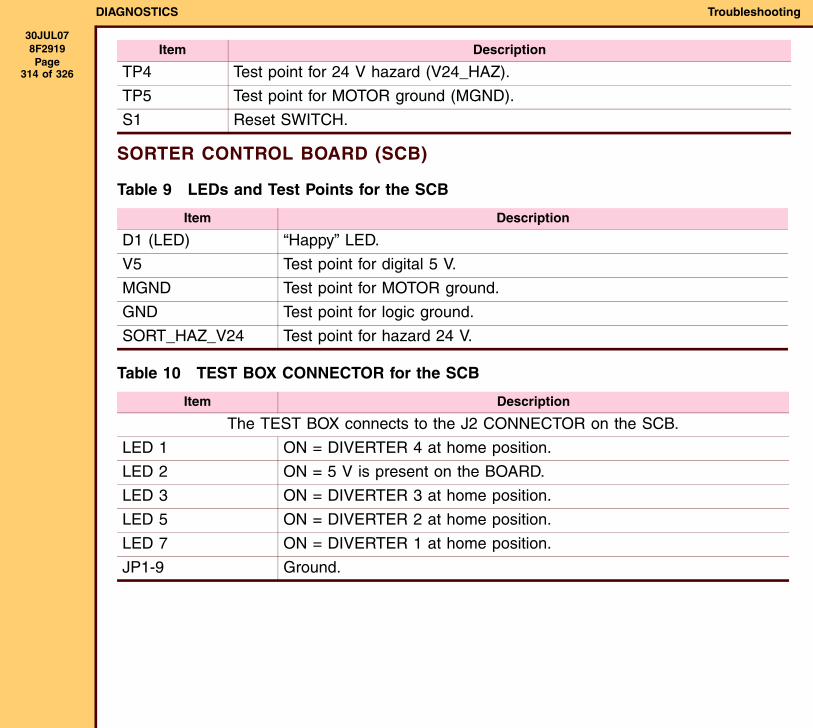
DIAGNOSTICS Troubleshooting
30JUL078F2919 Page
314 of 326
SORTER CONTROL BOARD (SCB)
Table 9 LEDs and Test Points for the SCB
Table 10 TEST BOX CONNECTOR for the SCB
TP4 Test point for 24 V hazard (V24_HAZ).
TP5 Test point for MOTOR ground (MGND).
S1 Reset SWITCH.
Item Description
D1 (LED) “Happy” LED.
V5 Test point for digital 5 V.
MGND Test point for MOTOR ground.
GND Test point for logic ground.
SORT_HAZ_V24 Test point for hazard 24 V.
Item Description
The TEST BOX connects to the J2 CONNECTOR on the SCB.
LED 1 ON = DIVERTER 4 at home position.
LED 2 ON = 5 V is present on the BOARD.
LED 3 ON = DIVERTER 3 at home position.
LED 5 ON = DIVERTER 2 at home position.
LED 7 ON = DIVERTER 1 at home position.
JP1-9 Ground.
Item Description
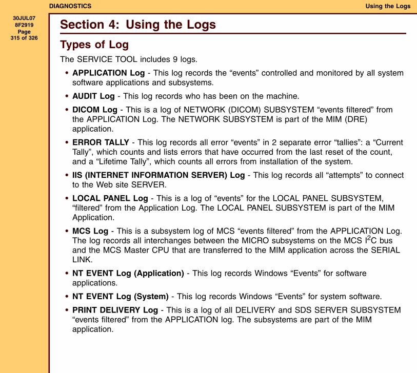
DIAGNOSTICS Using the Logs
30JUL078F2919 Page
315 of 326
Section 4: Using the Logs
Types of LogThe SERVICE TOOL includes 9 logs.
• APPLICATION Log - This log records the “events” controlled and monitored by all system software applications and subsystems.
• AUDIT Log - This log records who has been on the machine.
• DICOM Log - This is a log of NETWORK (DICOM) SUBSYSTEM “events filtered” from the APPLICATION Log. The NETWORK SUBSYSTEM is part of the MIM (DRE) application.
• ERROR TALLY - This log records all error “events” in 2 separate error “tallies”: a “Current Tally”, which counts and lists errors that have occurred from the last reset of the count, and a “Lifetime Tally”, which counts all errors from installation of the system.
• IIS (INTERNET INFORMATION SERVER) Log - This log records all “attempts” to connect to the Web site SERVER.
• LOCAL PANEL Log - This is a log of “events” for the LOCAL PANEL SUBSYSTEM, “filtered” from the Application Log. The LOCAL PANEL SUBSYSTEM is part of the MIM Application.
• MCS Log - This is a subsystem log of MCS “events filtered” from the APPLICATION Log. The log records all interchanges between the MICRO subsystems on the MCS I2C bus and the MCS Master CPU that are transferred to the MIM application across the SERIAL LINK.
• NT EVENT Log (Application) - This log records Windows “Events” for software applications.
• NT EVENT Log (System) - This log records Windows “Events” for system software.
• PRINT DELIVERY Log - This is a log of all DELIVERY and SDS SERVER SUBSYSTEM “events filtered” from the APPLICATION log. The subsystems are part of the MIM application.
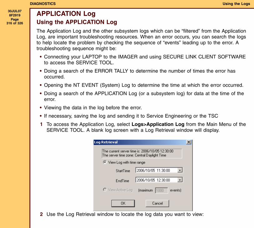
DIAGNOSTICS Using the Logs
30JUL078F2919 Page
316 of 326
APPLICATION LogUsing the APPLICATION LogThe Application Log and the other subsystem logs which can be “filtered” from the Application Log, are important troubleshooting resources. When an error occurs, you can search the logs to help locate the problem by checking the sequence of “events” leading up to the error. A troubleshooting sequence might be:
• Connecting your LAPTOP to the IMAGER and using SECURE LINK CLIENT SOFTWARE to access the SERVICE TOOL.
• Doing a search of the ERROR TALLY to determine the number of times the error has occurred.
• Opening the NT EVENT (System) Log to determine the time at which the error occurred.
• Doing a search of the APPLICATION Log (or a subsystem log) for data at the time of the error.
• Viewing the data in the log before the error.
• If necessary, saving the log and sending it to Service Engineering or the TSC
1 To access the Application Log, select Logs>Application Log from the Main Menu of the SERVICE TOOL. A blank log screen with a Log Retrieval window will display.
2 Use the Log Retrieval window to locate the log data you want to view:
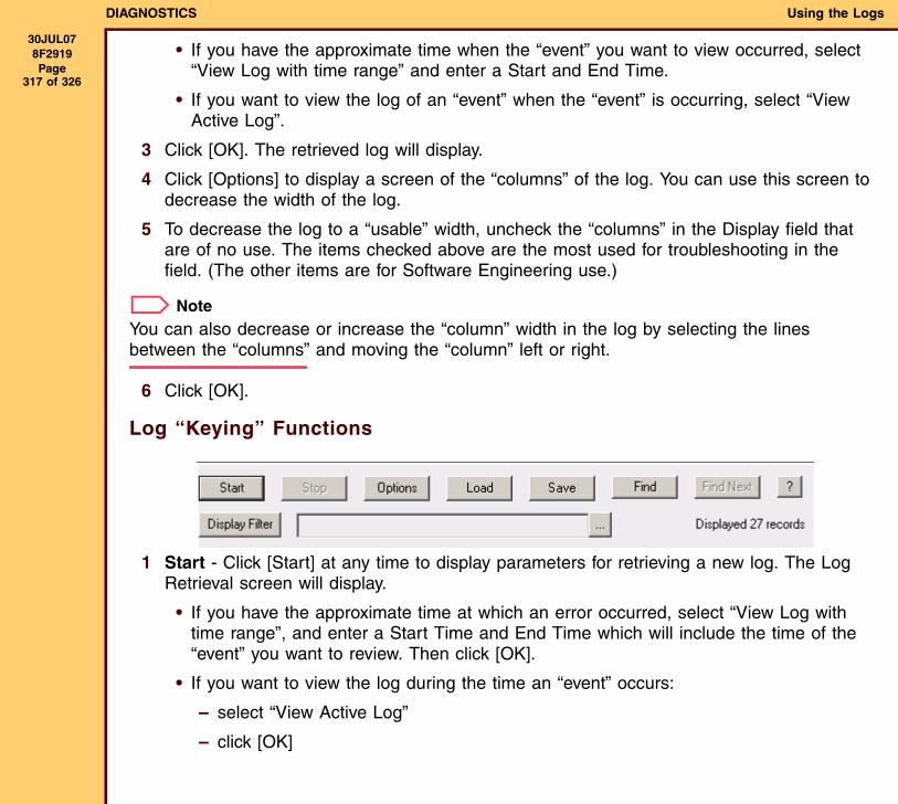
DIAGNOSTICS Using the Logs
30JUL078F2919 Page
317 of 326
• If you have the approximate time when the “event” you want to view occurred, select “View Log with time range” and enter a Start and End Time.
• If you want to view the log of an “event” when the “event” is occurring, select “View Active Log”.
3 Click [OK]. The retrieved log will display.
4 Click [Options] to display a screen of the “columns” of the log. You can use this screen to decrease the width of the log.
5 To decrease the log to a “usable” width, uncheck the “columns” in the Display field that are of no use. The items checked above are the most used for troubleshooting in the field. (The other items are for Software Engineering use.)
NoteYou can also decrease or increase the “column” width in the log by selecting the lines between the “columns” and moving the “column” left or right.
6 Click [OK].
Log “Keying” Functions
1 Start - Click [Start] at any time to display parameters for retrieving a new log. The Log Retrieval screen will display.
• If you have the approximate time at which an error occurred, select “View Log with time range”, and enter a Start Time and End Time which will include the time of the “event” you want to review. Then click [OK].
• If you want to view the log during the time an “event” occurs:
– select “View Active Log”
– click [OK]
DIAGNOSTICS Using the Logs
30JUL078F2919 Page
318 of 326
2 Stop - Click [Stop] at any time during the time a log is loading to stop the loading process.
3 Options - Click [Options] to display a screen of the log “columns” you want to display.
• Select the name of each “column” you want to display in the log. The “columns” selected above are of the most use for your purposes.
• Click [OK] to display the log.
4 Find - Click [Find] to search for an area in the log that you can identify by words or numbers, for example, an error code.
• Enter the combination of words and numbers you want to locate in the “Find what” window.
• Click [Find] to search the log.
5 Save - Click [Save] to save a log to a folder on your LAPTOP.
• Use the cursor to select the area of the log you want to save.
• Select the folder on the LAPTOP, for example Log Files.
• Enter a File name and click [Save].
NoteYour LAPTOP must have LOCAL LOG VIEWER SOFTWARE to view the logs.
6 Display “Filter” - Click [Display Filter] to display a screen that will allow you to “filter” the log to decrease the quantity of log data for analytical use.
DIAGNOSTICS Using the Logs
30JUL078F2919 Page
319 of 326
Using Advanced “Filtering”This section explains the use of the “filtering” function. For example: Modalities are not able to select the IMAGER because the current number of “scp associations” has reached and remains at the limit (12). You can use the “filtering” function to search for key words and numbers in the log to locate the information to solve the problem. See the following example search.
1 Access the Application Log and use the Log Retrieval window to select the time within which the IMAGER problem occurred.
2 Click [OK] to capture the log data.
3 Select “Display Filter”.
4 Under the “Basic” tab, select:
• “Enable Basic Filter”
• “Test contains”
5 Type the words and numbers that you want to search on. In this example, “scp assoc” was selected to appear in the “events” in the log you want to view.
6 Click [OK] to search the log for the selected test.
7 Note that the search retrieved only log items that include the words “scp assoc”. Also note that the log includes 1,688 records. To decrease the data, do additional “filtering”.
8 Click [Display Filter].
9 Select the “Advanced” tab.
10 Select “Enable Advanced filter” and fill in the first “Field” (see above). This adds the word up to the original search words “scp assoc”.
11 Click [OK] to retrieve all the “scp associations” that were up (running) during the time that was selected.
12 Note that this search retrieved only 9 records, indicating that 9 “associations” were up during the time selected.
13 Do another advanced search for “scp associations” that went down during the selected time.
DIAGNOSTICS Using the Logs
30JUL078F2919 Page
320 of 326
14 Note in the retrieved data that only 5 “associations” are indicated “down”.
15 A comparison of the up and down logs indicate that the “leonardo” modality continued to add “associations” without closing down “associations” until the limit of 12 “associations” was reached. This prevented new “associations” from occurring.
Contents of the LogEach line of the log documents an “event”. Each “event” has 16 “columns” of information. Only 4 or 5 of these “columns” are of use to the FE. (These are in “boldface” in the list below.) The other data is for use by software engineering. To decrease the size of the log, these “columns” should be removed from the viewed log by the Options function described in the preceding section. The “columns”, from left to right, include:
1 “Event Type” - This “column” provides the same information in the Level “column”. It describes the level provided for the “event”. The levels from highest to lowest are: TRACE (Level 6), DEBUG (5), DIAG (4), INFO (3), WARNING (2), ERROR (1), and FATAL ERROR (0).
2 “Time”- Provides the time of the “event”, down to 1/100th of a second. The time is of use for locating “events” in the log.
3 Code - Code for an “event”. Normally an error code.
4 “Text”- This “column” describes the “event”.
5 “App”- The software application in which the “event” occurred. The applications are: “MIM”, “DV6800”, and “Service Platform”.
6 Subsystem - The software subsystem within the application. These include subsystems of both the MIM and the 6800 LASER IMAGER, described in the tables below.
Subsystems for the MIM include:
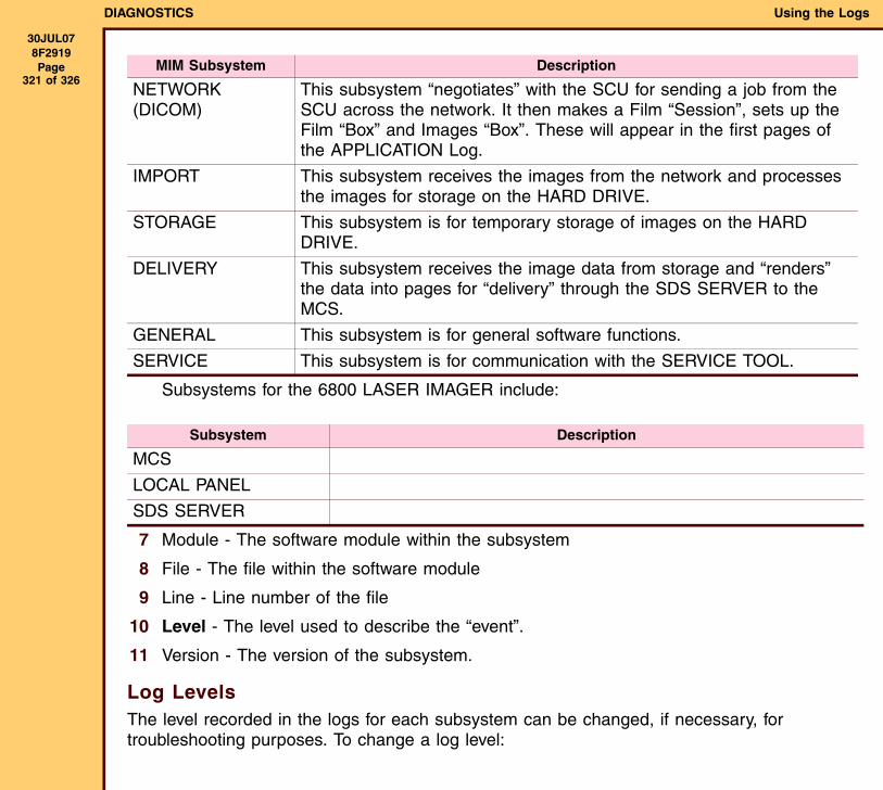
DIAGNOSTICS Using the Logs
30JUL078F2919 Page
321 of 326
Subsystems for the 6800 LASER IMAGER include:
7 Module - The software module within the subsystem
8 File - The file within the software module
9 Line - Line number of the file
10 Level - The level used to describe the “event”.
11 Version - The version of the subsystem.
Log LevelsThe level recorded in the logs for each subsystem can be changed, if necessary, for troubleshooting purposes. To change a log level:
MIM Subsystem Description
NETWORK (DICOM)
This subsystem “negotiates” with the SCU for sending a job from the SCU across the network. It then makes a Film “Session”, sets up the Film “Box” and Images “Box”. These will appear in the first pages of the APPLICATION Log.
IMPORT This subsystem receives the images from the network and processes the images for storage on the HARD DRIVE.
STORAGE This subsystem is for temporary storage of images on the HARD DRIVE.
DELIVERY This subsystem receives the image data from storage and “renders” the data into pages for “delivery” through the SDS SERVER to the MCS.
GENERAL This subsystem is for general software functions.
SERVICE This subsystem is for communication with the SERVICE TOOL.
Subsystem Description
MCS
LOCAL PANEL
SDS SERVER
DIAGNOSTICS Using the Logs
30JUL078F2919 Page
322 of 326
1 From the SERVICE TOOL menu, select Configuration>System>Log Level.
2 Click [Modify].
3 From the drop-down menu for the subsystem, select the “Log Level” you want and click [Save].
NoteThe log levels, from lowest to highest are:
• “0 - Fatal Error”: Record only “fatal” errors
• “1 - Error”: Record all errors
• “2 - Warning”: Record warnings and all errors
• “3 - Information”: Record key “events”
• “4 - Diagnostic”: Provide a level of information for field troubleshooting.
• “5 - Debug”: Provide a level of information for software “debugging”.
• “6 - Trace”:
ImportantLevels higher than the recommended defaults can slow down the system. If you change a level to help diagnose a problem, return the level to the default value after completing troubleshooting.
DIAGNOSTICS Using the Logs
30JUL078F2919 Page
323 of 326
DICOM LogThis is a subsystem log that includes all MIM Network “events” pulled from an Application Log. Note that the Subsystem “column” includes only Network. See Sample Log 1 at the end of this section for descriptions of the “events” in the log.
ERROR TALLY LogThe logs include 2 lists of errors.
• A “Current Tally”, which lists the number of errors that have occurred from when the count for the errors was reset to 0.
• A “Lifetime Tally”, which lists the total count of all errors that have occurred during the operation of the IMAGER.
1 To access these logs, connect your LAPTOP to the SERVICE TOOL and select Logs>Error Tally. The “Current Error Tally” will display.
NoteThe error codes in the “tally” are by application: “DV6800”, “MIM”, or “Service Platform”.
a To reset the count for any error to 0, click [Select] for that error and then click [Reset] at the bottom of the screen.
b If you want to reset the count for all errors in the list, click [Select All] and then [Reset].
2 To access the “Lifetime Tally”, select “Lifetime”. Note that this screen does not include the Reset function.
3 To save:
a Click [Save] on the bottom of the ERROR TALLY screen.
b In the “Save Copy As” window, select the File Name of the folder on your LAPTOP to save the “Tally” in.
DIAGNOSTICS Using the Logs
30JUL078F2919 Page
324 of 326
c Click [Save].
NoteYour LAPTOP must have LOCAL LOG VIEWER SOFTWARE to view the saved log.
IIS LogThe INTERNET INFORMATION SYSTEM (IIS) log records all “attempts” to connect to the Web site SERVER. The log has the following “columns”:
• Time - “timestamp” of each “event”
• “Method” -
• Protocol -
• “Client” IP - IP Address of the
• Time “Taken” -
• URI “Stem” -
LOCAL PANEL LogThis is a subsystem log that includes all “events” for the LOCAL PANEL “filtered” from an Application Log. See Sample Log 1 at the end of this section for descriptions of the “events” in the log.
MCS LogThis is a subsystem log that includes all MCS “events” pulled from an Application Log. These are “events” of any of the MICRO subsystems on the MCS I2C bus. Note that each description of the “event” begins with FROM MCS. See Sample Log 1 at the end of this section for descriptions of the “events” in the log.
NT EVENT Log (Application)This is a log of all Windows “events” for software applications.
DIAGNOSTICS Using the Logs
30JUL078F2919 Page
325 of 326
NT EVENT Log (System)This is a log of Windows “events” for system software.
PRINT DELIVERY LogThis is a subsystem log that includes all DELIVERY and SDS SERVER SUBSYSTEM “events” pulled from an Application Log. Note that the subsystem “column” includes only these subsystems. See Sample Log 1 at the end of this section for descriptions of the “events” in the log.
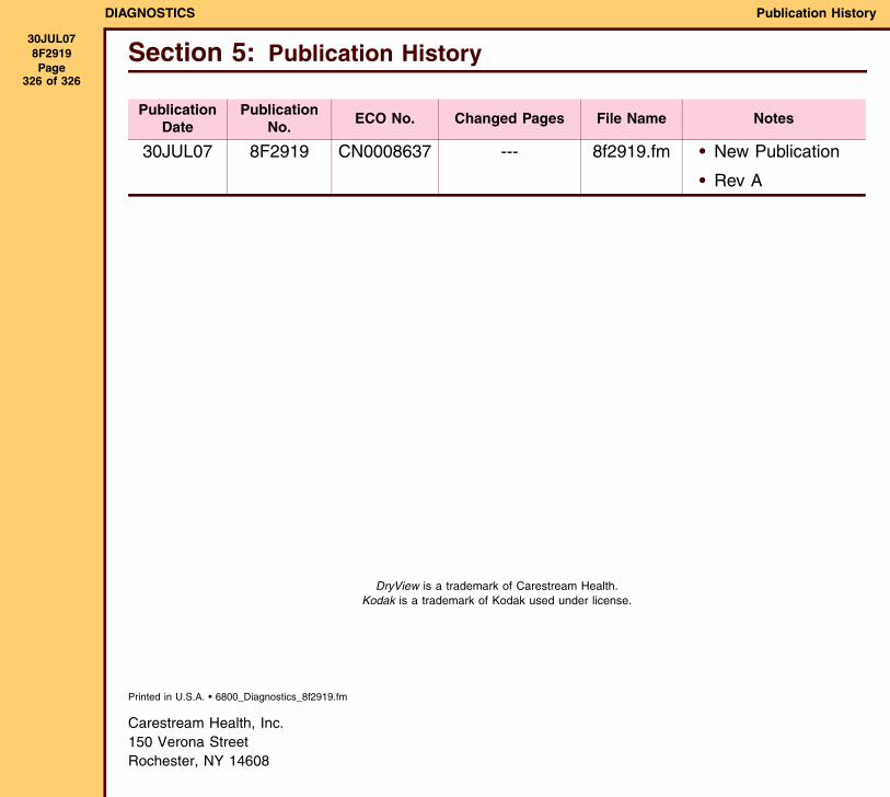
DIAGNOSTICS Publication History
30JUL078F2919 Page
326 of 326
Printed in U.S.A. • 6800_Diagnostics_8f2919.fm
Carestream Health, Inc.150 Verona StreetRochester, NY 14608
Section 5: Publication History
PublicationDate
PublicationNo.
ECO No. Changed Pages File Name Notes
30JUL07 8F2919 CN0008637 --- 8f2919.fm • New Publication
• Rev A
DryView is a trademark of Carestream Health.Kodak is a trademark of Kodak used under license.