
PnC TECH BUSAN - Catalog 2015 - 마비스, marbiss 2207‐11 Welding of thermoplastics – heated...
27
Transcript of PnC TECH BUSAN - Catalog 2015 - 마비스, marbiss 2207‐11 Welding of thermoplastics – heated...

1
Contents1. General information .......................................................................................................................... 2
2. Features – Applications ..................................................................................................................... 3
3. Features – Advantages ...................................................................................................................... 4
4. General Precautions .......................................................................................................................... 5
5. Features – Material Properties and Characteristics .......................................................................... 6
6. Features – Fiber Reinforced Pipe ...................................................................................................... 7
7. Operation Pressure, temperature and service life of Fiber Reinforced Pipes .................................. 7
8. Calculation of expansion and contraction ......................................................................................... 8
9. Compensating expansion and contraction ........................................................................................ 9
10. Bracket spacing ................................................................................................................................ 10
11. Pressure loss in PnC Fiber Pipes ...................................................................................................... 10
12. Socket Fusion Jointing – Hand Welding Tool ................................................................................... 12
13. Catalogue – PnC Fiber reinforced Pipes .......................................................................................... 15
14. Catalogue – Fittings ......................................................................................................................... 16
15. Certificates & Approvals .................................................................................................................. 24

2
1. Generalinformation
Abbreviations: Following abbreviations are used in this manual
d Outside diameter of pipe s Wall thickness of pipe DN Nominal diameter R Tapered male thread (pressure tight in thread) Rp Parallel female thread (pressure tight in thread) G Parallel thread (not pressure tight) PN Nominal pressure at 20⁰C IMO International Maritime Organization DIN German industry standard ISO International Standard DVS Code published by German institute for welding technology S Pipe series SDR Standard dimension ratio (d / s) PP‐R Polypropylene Random Copolymer l Liter / length m Meter W Watt Technical standards and codes relevant for this product line: Main product standard ISO 15874 Plastic piping systems for hot and cold water installations – Polypropylene PP DIN 8077 PP pipes sizes DIN 8078 PP pipes quality assurance standard Reference standards A.753 (18) IMO RESOLUTION ISO 9080 Determination of long term hydrostatic strength
ISO10508 Plastic piping systems for hot and cold water installations – Guidance for classification and design
ISO/TR 10501 Plastic piping systems for the transport of liquids under pressure – calculation of head losses
ISO/TR10358 Plastic pipes and fittings – combined chemical resistance classification table
DIN 16962 Pipe joints and elements for Polypropylene pressure pipelines
DVS 2207‐11 Welding of thermoplastics – heated tool welding of pipes, piping parts and panels made of PP
DVS 2210‐1 Industrial Pipelines made of thermoplastics – Planning and Execution of above ground pipes systems
3
2. Features–Applications
The PnC system is a highly versatile full plastic piping system using PP‐R (Poly Propylene – Random
Copolymer) as base material. PP‐R is one of the most versatile plastic materials available for plastic
piping systems. Its characteristics of high temperature and pressure resistance and outstanding impact
strength make it ideally suited for various applications in the Marine and Industrial field.
The PnC system has been design with focus on the Marine and Industrial field utilizing state of the art
European design technology and highly engineered production facilities.
PnC system can be used for a wide range of applications:
‐ Potable hot and cold water up to 95⁰C
‐ Sea Water sanitary pipes
‐ Air conditioning pipes in accommodation spaces
‐ Other non essential systems
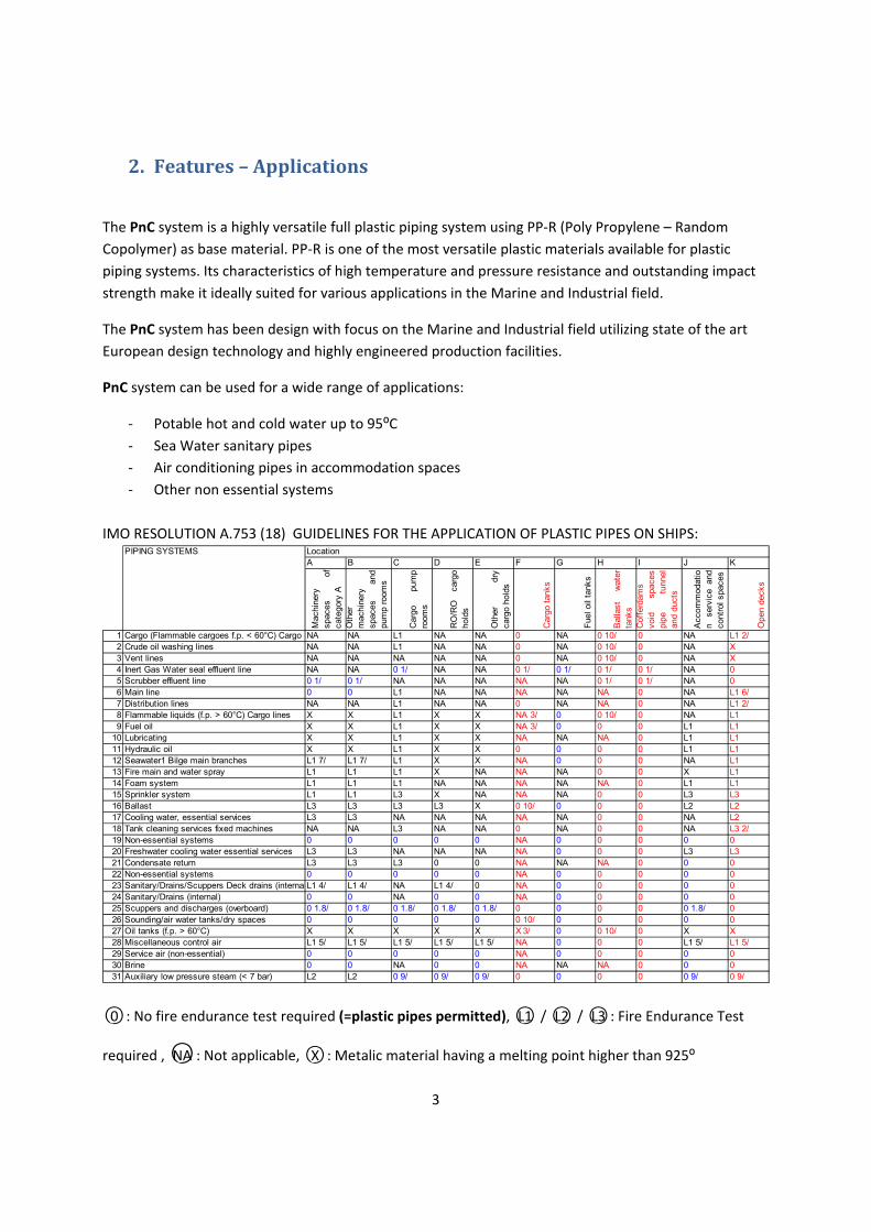
IMO RESOLUTION A.753 (18) GUIDELINES FOR THE APPLICATION OF PLASTIC PIPES ON SHIPS: PIPING SYSTEMS Location
A B C D E F G H I J K
Mac
hine
ry
spac
esof
cate
gory
AO
ther
m
achi
nery
sp
aces
and
pum
p ro
oms
Car
gopu
mp
room
s
RO
/RO
carg
oho
lds
Oth
erdr
yca
rgo
hold
s
Car
go t
anks
Fue
l oil
tank
s
Bal
last
wat
erta
nks
Cof
ferd
ams
void
spac
espi
petu
nnel
and
duct
s
Acc
omm
odat
ion
serv
ice
and
cont
rol s
pace
s
Ope
n de
cks
1 Cargo (Flammable cargoes f.p. < 60°C) Cargo lNA NA L1 NA NA 0 NA 0 10/ 0 NA L1 2/2 Crude oil washing lines NA NA L1 NA NA 0 NA 0 10/ 0 NA X3 Vent lines NA NA NA NA NA 0 NA 0 10/ 0 NA X4 Inert Gas Water seal effluent line NA NA 0 1/ NA NA 0 1/ 0 1/ 0 1/ 0 1/ NA 05 Scrubber effluent line 0 1/ 0 1/ NA NA NA NA NA 0 1/ 0 1/ NA 06 Main line 0 0 L1 NA NA NA NA NA 0 NA L1 6/7 Distribution lines NA NA L1 NA NA 0 NA NA 0 NA L1 2/8 Flammable liquids (f.p. > 60°C) Cargo lines X X L1 X X NA 3/ 0 0 10/ 0 NA L19 Fuel oil X X L1 X X NA 3/ 0 0 0 L1 L1
10 Lubricating X X L1 X X NA NA NA 0 L1 L111 Hydraulic oil X X L1 X X 0 0 0 0 L1 L112 Seawater1 Bilge main branches L1 7/ L1 7/ L1 X X NA 0 0 0 NA L113 Fire main and water spray L1 L1 L1 X NA NA NA 0 0 X L114 Foam system L1 L1 L1 NA NA NA NA NA 0 L1 L115 Sprinkler system L1 L1 L3 X NA NA NA 0 0 L3 L316 Ballast L3 L3 L3 L3 X 0 10/ 0 0 0 L2 L217 Cooling water, essential services L3 L3 NA NA NA NA NA 0 0 NA L218 Tank cleaning services fixed machines NA NA L3 NA NA 0 NA 0 0 NA L3 2/19 Non-essential systems 0 0 0 0 0 NA 0 0 0 0 020 Freshwater cooling water essential services L3 L3 NA NA NA NA 0 0 0 L3 L321 Condensate return L3 L3 L3 0 0 NA NA NA 0 0 022 Non-essential systems 0 0 0 0 0 NA 0 0 0 0 023 Sanitary/Drains/Scuppers Deck drains (internalL1 4/ L1 4/ NA L1 4/ 0 NA 0 0 0 0 024 Sanitary/Drains (internal) 0 0 NA 0 0 NA 0 0 0 0 025 Scuppers and discharges (overboard) 0 1.8/ 0 1.8/ 0 1.8/ 0 1.8/ 0 1.8/ 0 0 0 0 0 1.8/ 026 Sounding/air water tanks/dry spaces 0 0 0 0 0 0 10/ 0 0 0 0 027 Oil tanks (f.p. > 60°C) X X X X X X 3/ 0 0 10/ 0 X X28 Miscellaneous control air L1 5/ L1 5/ L1 5/ L1 5/ L1 5/ NA 0 0 0 L1 5/ L1 5/29 Service air (non-essential) 0 0 0 0 0 NA 0 0 0 0 030 Brine 0 0 NA 0 0 NA NA NA 0 0 031 Auxiliary low pressure steam (< 7 bar) L2 L2 0 9/ 0 9/ 0 9/ 0 0 0 0 0 9/ 0 9/
○0 : No fire endurance test required (=plastic pipes permitted), ○L1 / ○L2 / ○L3 : Fire Endurance Test
required , ○NA : Not applicable, ○X : Metalic material having a melting point higher than 925⁰

4
3. Features–Advantages
Weight savings: The PnC system is up to 8 times lighter than metal systems
Corrosion resistant: Corrosion free solution even with sea water, aggressive waters and chemicals.
No leakages or discolorations of the water throughout the operation period of
the piping system.
Welded connection: Heat fusion produces homogeneous joints between pipes and fittings. Joints can
withstand equal or higher pressure and temperatures than the fittings and pipes
and are not affected by corrosion and vibrations.
Safe connection Heat fusion of PP‐R pipes and fittings is simple and can be done following the
method: instructions in this manual. An electrical heating element is used to melt pipe
and fittings, no open flame is necessary for welding.
Fire safety: PP‐R has passed the low flame spread and burns halogen free and is therefore
safe to install onboard ships.
Low heat loss: The heat loss of PP‐R pipes is much lower than metal pipes. Therefore insulation
materials can be omitted or reduced.
Fast installation: PP‐R is fast and easy to install. The system can be pressurized directly after
cooling periods. Pipe joints can be made in seconds without the need of a fire
watch or heavy installation equipments. Pipes and fitting are light and can all be
carried, lifted and installed by hand.
Fiber Layer Pipe: The fiber layer increases pressure and temperature resistance of the pipe and
allows for absolutely rigid installation with a linear expansion and contraction
similar to metal pipes.
Environmentally: Fully recyclable. Used PP‐R pipes can be re‐used for production of various plastic
friendly: articles like waste bins, plastic pallets, packing materials and so forth.
Production of plastic pipes requires far less energy than the production of steel
and copper pipes.
1m of Pipe PP‐R Copper (A) Steel (SCH40)
d20 – 1/2” 0.15 kg 0.57 kg 1.27 kg
d63 – 2” 1.45 kg 3.06 kg 5.45 kg
d90 – 3” 2.90 kg 5.99 kg 11.3 kg

5
4. GeneralPrecautions
Pipe Bending
Do not bend the fiber reinforced
pipes by using hot air or open flame.
6
5. Features–MaterialPropertiesandCharacteristics
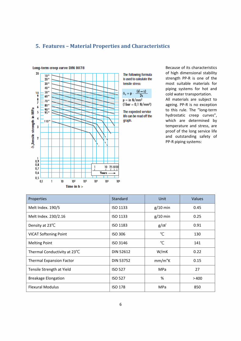
Properties Standard Unit Values
Melt Index. 190/5 ISO 1133 g/10 min 0.45
Melt Index. 230/2.16 ISO 1133 g/10 min 0.25
Density at 23℃ ISO 1183 g/㎤ 0.91
VICAT Softening Point ISO 306 ℃ 130
Melting Point ISO 3146 ℃ 141
Thermal Conductivity at 23℃ DIN 52612 W/mK 0.22
Thermal Expansion Factor DIN 53752 mm/m°K 0.15
Tensile Strength at Yield ISO 527 MPa 27
Breakage Elongation ISO 527 % >400
Flexural Modulus ISO 178 MPa 850
Because of its characteristics of high dimensional stability strength PP‐R is one of the most suitable materials for piping systems for hot and cold water transportation. All materials are subject to ageing. PP‐R is no exception to this rule. The ”long‐term hydrostatic creep curves”, which are determined by temperature and stress, are proof of the long service life and outstanding safety of PP‐R piping systems:

7
6. Features–FiberReinforcedPipe
In cooperation with laboratories and industry experts our R&D team has developed a unique fiber
reinforced PP‐R pipe. The fiber reinforcement increases the temperature stability and strength of the
pipe far above normal PP‐R pipes.
This three layer fiber pipe brings numerous advantages to end users and installers:
‐ Higher safety and increase in pressure and temperature resistance
‐ Hygienically safe because fibers do not have medium contact
‐ Rigid pipes require less pipe supports
‐ Fiber reinforcement reduces thermal expansion to a minimum
‐ Homogenous connection method by heat fusion
‐ High flow rate because of large inner diameter
Difference of inner diameter compared
between a standard SDR6 Pipe and the
PnC Fiber reinforced pipe
7. OperationPressure,temperatureandservicelifeofFiberReinforcedPipes
Temp Years of Operation
1 5 10 25 50
Continuous Operation pressure in bar
20⁰C 28.1 26.3 25.6 24.8 24.1
30⁰C 23.9 22.4 21.7 20.9 20.4
40⁰C 20.2 18.9 18.4 17.6 16.7
50⁰C 17.2 15.9 15.5 14.9 14.4
60⁰C 14.4 13.4 12.9 12.5 11.9
70⁰C 12.2 11.2 11.0 9.5 8.0

8
8. Calculationofexpansionandcontraction
Plastic pipes are subject to thermal expansion and contractor far greater than metal pipes. The special
fiber layer of the PnC pipe reduces expansion and contraction significantly compared to standard plastic
(PP‐R) pipes.
Thermal expansion coefficient of standard PP‐R pipe: 0.15 mm/m⁰C
Thermal expansion coefficient of PnC fiber PP‐R pipe: 0.035 mm/m⁰C
The thermal expansion of a PnC fiber pipe is therefore similar to that of a copper pipe.
Calculation of change in length:
For straight loops of more than 40m and temperature changes of more than 40⁰C it is necessary to
control and take measures to absorb thermal expansion and contraction.
Example: L = 40m ΔT = 40⁰C Α = 0.035 mm/m⁰C ΔL = 40x40x0.035 = 56mm
9
9. Compensatingexpansionandcontraction
The expansion and contraction of PnC Fiber pipes is limited to an absolute minimum as the above
calculation shows. Should special situations require control and absorption of expansion and contraction
expansion loops and flexible legs can installed:
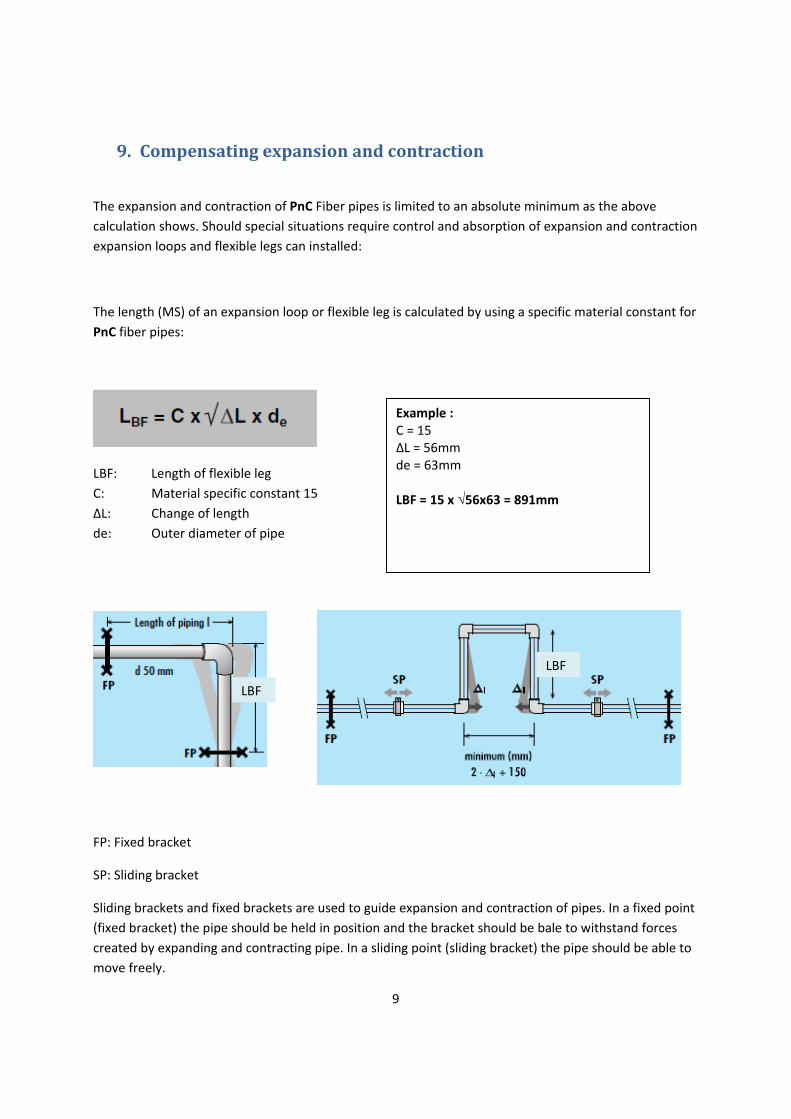
The length (MS) of an expansion loop or flexible leg is calculated by using a specific material constant for
PnC fiber pipes:
LBF: Length of flexible leg
C: Material specific constant 15
ΔL: Change of length
de: Outer diameter of pipe
FP: Fixed bracket
SP: Sliding bracket
Sliding brackets and fixed brackets are used to guide expansion and contraction of pipes. In a fixed point
(fixed bracket) the pipe should be held in position and the bracket should be bale to withstand forces
created by expanding and contracting pipe. In a sliding point (sliding bracket) the pipe should be able to
move freely.
LBF
LBF
Example : C = 15 ΔL = 56mm de = 63mm LBF = 15 x √56x63 = 891mm

10
10.BracketSpacing.
Rigidity is one of the advantages of PnC fiber pipes. The rigid pipes remain straight even at high
temperatures and require fewer brackets than a normal PP‐R pipe.
Pipe diameter d (mm)
20 25 32 40 50 63 75 90
Bracket spacing in cm
Cold 90 105 120 135 155 175 185 195
Tempered 85 95 110 125 145 165 175 185
Hot 70 80 95 110 130 145 155 165 Temperature ranges: Cold: 20°C; Tempered: 50°C; Hot: 70°C
11.PressurelossinPnCFiberPipes&Fittings.

11
Description Symbol Coefficient of
Resistance
Socket 0.25
Elbow 90° 2.00
Elbow 45° 0.60
Tee 90° 1.80
Reduced Tee 90° 3.60
Tee 90° 1.30
Reduced Tee 90° 2.60
Tee 90° 4.20
Reduced Tee 90° 9.00
Tee 90° 2.20
Reduced Tee 90° 5.00
Threaded Fitting, Male 0.40
Threaded Elbow, Female 2.20

12
12.SocketFusionJointing–HandWeldingTool
Socket fusion process
1. Create permissible working conditions, e.g. dry and clean
2. Connection welding device to the mains or generator and check its function
3. Clean the heating bushes with suitable cleaning agent (e.g. industrial alcohol), with unused, absorbent,
non‐fraying and non‐died paper
4. Check welding temperature (250°C ‐ 270°C)
5. Clean all joining faces of pipe and fitting with suitable cleaning agent (e.g. industrial alcohol), with
unused, absorbent, non‐fraying and non‐died paper
6. Cut the pipe at right angle and remove any burrs, bevel if necessary. Mark insertion depth.
7. Simultaneously push the fitting and the pipe on to the heating spigot respectively into the heating
bush as far as the stop respectively the mark. Avoid pushing the pipe too deep (bump into the end of
the heating bush) or not deep enough.
8. Elapse heating time according to below table
9. Pull fitting and pipe off the heating bush / spigot and immediately push them together as far as the
mark or stop (see below table for max. change over time). Do not rotate pipe and fitting after join for
more than 15°.
10. Let the joint cool down. Only subject the welded joint to mechanical loads when total cooling time
according to below table has elapsed.
11. The outer fusion bead must be inspected. A double bead must be uninterrupted all around the pipe circumference.
1 2 3 4 5 6
Outside Diameter Insertion depth Heating Change ‐ over Cooling
d 250°C ‐ 270°C Fixed Total
mm mm s s s min
20 14 6 4 6 2
25 16 8 4 10 2
32 18 10 6 10 4
40 20 15 6 20 4
50 23 22 6 20 4
63 26 30 8 30 6
75 28 40 8 30 6
90 31 50 8 40 6
13
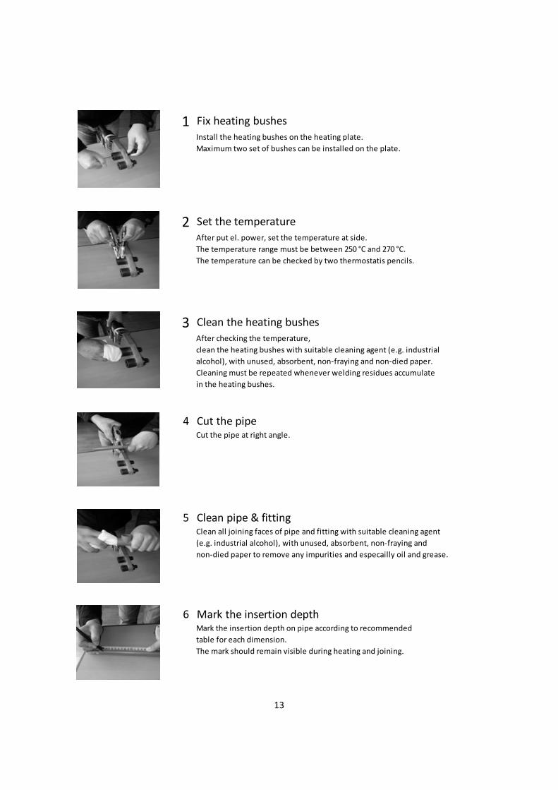
1 Fix heating bushes
Install the heating bushes on the heating plate.
Maximum two set of bushes can be installed on the plate.
2 Set the temperature
After put el. power, set the temperature at side.
The temperature range must be between 250 °C and 270 °C.
The temperature can be checked by two thermostatis pencils.
3 Clean the heating bushes
After checking the temperature,
clean the heating bushes with suitable cleaning agent (e.g. industrial
alcohol), with unused, absorbent, non‐fraying and non‐died paper.
Cleaning must be repeated whenever welding residues accumulate
in the heating bushes.
4 Cut the pipeCut the pipe at right angle.
5 Clean pipe & fittingClean all joining faces of pipe and fitting with suitable cleaning agent
(e.g. industrial alcohol), with unused, absorbent, non‐fraying and
non‐died paper to remove any impurities and especailly oil and grease.
6 Mark the insertion depthMark the insertion depth on pipe according to recommended
table for each dimension.
The mark should remain visible during heating and joining.
14
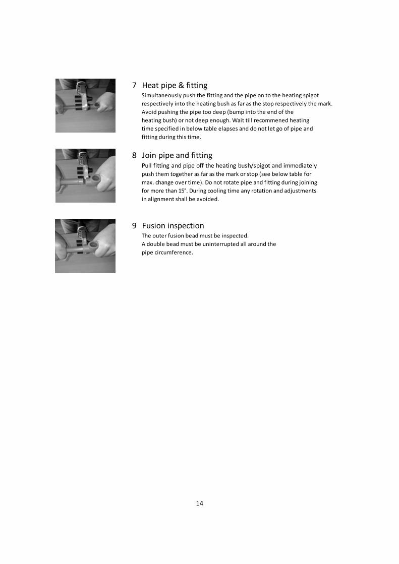
7 Heat pipe & fittingSimultaneously push the fitting and the pipe on to the heating spigot
respectively into the heating bush as far as the stop respectively the mark.
Avoid pushing the pipe too deep (bump into the end of the
heating bush) or not deep enough. Wait till recommened heating
time specified in below table elapses and do not let go of pipe and
fitting during this time.
8 Join pipe and fittingPull fitting and pipe off the heating bush/spigot and immediatelypush them together as far as the mark or stop (see below table for
max. change over time). Do not rotate pipe and fitting during joining
for more than 15°. During cooling time any rotation and adjustments
in alignment shall be avoided.
9 Fusion inspectionThe outer fusion bead must be inspected.
A double bead must be uninterrupted all around the
pipe circumference.

15
13.Catalogue–PnCFiberreinforcedPipes
PnC Fiber reinforced Pipes SDR 7.4 (PN16)
Material: PP‐R and PnC Fiber Reinforced PP‐R
Standards: DIN 8077 / DIN 8078 / ISO15874‐2
d x s
Article No.
Kg / m
Length
20 x 2.8 20 20 001 0.16 4m
25 x 3.5 20 25 002 0.24 4m
32 x 4.4 20 32 003 0.38 4m
40 x 5.5 20 40 004 0.58 4m
50 x 6.9 20 50 005 0.91 4m
63 x 8.6 20 63 006 1.42 4m
75 x 10.3 20 75 007 2.05 4m
90 x 12.3 20 90 008 2.90 4m

16
14.Catalogue–Fittings
Sockets
Article No.
d
da
k
t
l
20 20 021 20 29 3 14.5 32 20 25 022 25 34 3 16 35 20 32 023 32 43 4.5 18 40.5 20 40 024 40 55 7.5 20 47.5 20 50 025 50 67 6 23.5 53 20 63 026 63 88 6.5 27 60.5 20 75 027 75 98 8 31 70
Elbow 90°
Article No.
d
da
k
t
20 20 041 20 29 11 14.5 20 25 042 25 34 13.5 16 20 32 043 32 43 18 18 20 40 044 40 55 22 20 20 50 045 50 66 26.5 25.5 20 63 046 63 88 33.5 27 20 75 047 75 98 39 31
Elbow 45°
Article No.
d
da
k
t
20 20 061 20 29 5 14.5 20 25 062 25 34 6 16 20 32 063 32 43 7.5 18 20 40 064 40 55 10 20 20 50 065 50 65 11.5 25 20 63 066 63 88 16 27 20 75 067 75 98 18 31
17
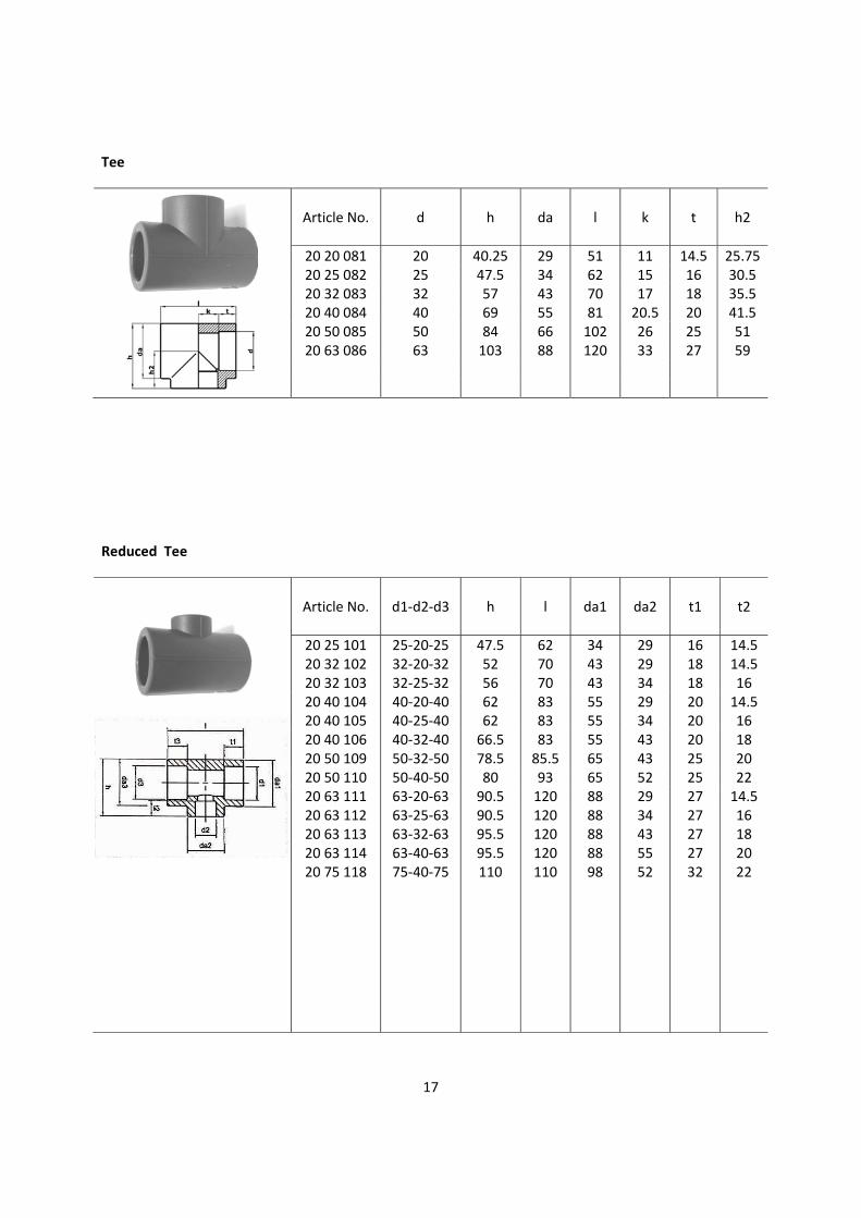
Tee
Article No.
d
h
da
l
k
t
h2
20 20 081 20 40.25 29 51 11 14.5 25.75 20 25 082 25 47.5 34 62 15 16 30.5 20 32 083 32 57 43 70 17 18 35.5 20 40 084 40 69 55 81 20.5 20 41.5 20 50 085 50 84 66 102 26 25 51 20 63 086 63 103 88 120 33 27 59
Reduced Tee
Article No.
d1‐d2‐d3
h
l
da1
da2
t1
t2
20 25 101 25‐20‐25 47.5 62 34 29 16 14.5 20 32 102 32‐20‐32 52 70 43 29 18 14.5 20 32 103 32‐25‐32 56 70 43 34 18 16 20 40 104 40‐20‐40 62 83 55 29 20 14.5 20 40 105 40‐25‐40 62 83 55 34 20 16 20 40 106
20 50 109 40‐32‐4050‐32‐50
66.5 78.5
83 85.5
55 65
43 43
20 25
18 20
20 50 110 50‐40‐50 80 93 65 52 25 22 20 63 111 63‐20‐63 90.5 120 88 29 27 14.5
20 63 112 20 63 113 20 63 114 20 75 118
63‐25‐6363‐32‐6363‐40‐6375‐40‐75
90.5 95.5 95.5 110
120 120 120 110
88 88 88 98
34 43 55 52
27 27 27 32
16 18 20 22

18
Reducer
Article No.
d2‐d1
da
t2
t1
l
20 25 151 25‐20 34 16 14.5 38 20 32 152 32‐20 43 18 14.5 36.5 20 32 153 32‐25 43 18 16 38.5 20 40 154 40‐20 55 20 14.5 45 20 40 155 40‐25 55 20 16 50 20 40 156 40‐32 55 20 18 50
20 50 160 20 63 161 20 63 162 20 63 164 20 63 165 20 75 166
50‐40 63‐20 63‐25 63‐40 63‐50 75‐63
67 88 88 88 88 98
23.5 27 27 27 27 31
20 14.5 16 20 23.5 27
54 58 58 65 65 67
Cap
Article No.
d
da
l
t
20 20 181 20 29 25.5 14.5

19
Male Thread Adaptor
Article No.
d‐R
d1
l
t
k
a
20 20 301 20‐1/2” 38.5 54 14.5 41 13 20 20 302 20‐3/4” 45 56 14.5 41 15 20 25 303 25‐3/4” 45 58 16 43 15 20 40 305 40‐1 1/4” 74 85 20 66 19 20 63 307 63‐2” 94 95 27 74 22
Female Thread Adaptor
Article No.
d‐Rp
d1
l
t
k
a
20 20 321 20‐1/2” 38.5 41 14.5 26.5 13 20 25 322 25‐3/4” 45 42 16 26 15 20 40 324 40‐1 1/4” 72 68.5 21.9 47 20
Female Thread Elbow
Article No.
d‐Rp
h
da
t
k1
k2
a
20 20 361 20‐1/2” 48 29 14.5 15.5 23.5 13
20
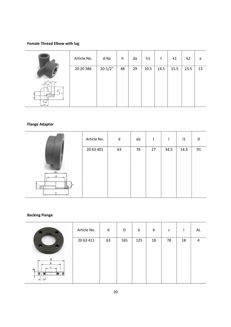
Female Thread Elbow with lug
Article No.
d‐Rp
h
da
h1
t
k1
k2
a
20 20 386 20‐1/2” 48 29 10.5 14.5 15.5 23.5 13
Flange Adaptor
Article No.
d
da
t
l
l1
D
20 63 401 63 76 27 34.5 14.5 91
Backing Flange
Article No.
d
D
k
b
c
l
AL
20 63 411 63 165 125 18 78 18 4

21
Flange Seal
Article No.
d
d1
d2
s1
s2
20 63 421 63 63 107 4 5
Ball Valves
Article No.
d
L1
L2
L3
D
H
E
20 20 501 20 98 57 68 50.5 48 67 20 25 502 25 110 65 78.5 59 57 81.5 20 32 503 32 120 71.5 84.5 70.5 64 81.5 20 40 504 40 142 86 100 86 83 95.5 20 50 505 50 154 89.5 107 100 89 95.5 20 63 506 63 174 102 118 125.5 115 144
Electrofusion Sockets
Article No.
d
h
L
20 20 601 20 25 602 20 32 603 20 40 604 20 50 605 20 63 606 20 75 607
20 52 58 65 75 87 100 114
70 70 70 85 88 98 125
25 32 40 50 63 75

22
Tube Adapter
Article No.
d‐Ø
da
l
t
k
a
20 20 391 20‐10.0 34 62 15 37 25 20 20 392 20‐12.7 34 62 15 37 25
Tube Elbow
Article No.
d‐Ø
h
da
t
k1
k2
a
20 20 395 20‐10.0 43.5 29.5 15 27 32.8 25 20 20 396 20‐12.7 43.5 29.5 15 27 32.8 25

23
Hand Welding tools
Article No.
d
Voltage
Weight
kg
20 00 700 20‐63 230V / 800W 6
Hand Welding Tool set, including : 1. 800W thermostat controlled heating element 2. Heating bushes d20 – d63 3. Floor and table stand 4. Transport case and accessories
Heating Bushes
Article No.
d
20 20 701 20 20 25 702 25
20 32 703 32 20 40 704 40 20 50 705 50 20 63 706 63 20 75 707 75 20 90 708 90
Bench Type Welding Machine
Article No.
d
Voltage
Weight
kg
20 00 741 20‐90 230V / 1000W 54
Bench Type Welding Machine set, including: 1. 1000W electronic controlled heating element 2. Heating bushes d20 ‐ d90 3. Clamping elements d20 ‐ d90 4. Floor stand, tripod pipe support 5. Tool box

24
Electrofusion Welding Tool
Article No.
d
Voltage
Weight
kg
20 00 801 20‐125 230V / 2000W 8
Electrofusion Welding Tool set, including: 1. Scan reader / optical pen / printer connector 2. Welding cable 3. Welding connectors 4. Power supply cable 5. Transport bag 6. Scan reader
Weldable materials : PE / PP / PP‐R Dimensions (W x D x H) : 200 x 250 x 210 mm

25
15.Certificates&Approvals
ISO 9001 : 2008 Certificate DNV Type Approval Certificate
BV Type Approval Certificate ABS Type Approval Certificate

26
KR Type Approval Certificate LR Type Approval Certificate