Lecture 15-18 Ch09 Complex Numbers
46
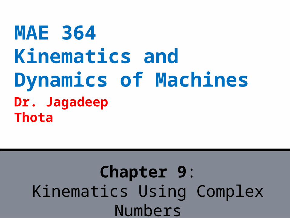
Dr. Jagadeep Thota MAE 364 Kinematics and Dynamics of Machines Chapter 9: Kinematics Using Complex Numbers
-
Upload
ameershamieh -
Category
Documents
-
view
220 -
download
1
description
Brief presentation on introducing and working with complex numbers.
Transcript of Lecture 15-18 Ch09 Complex Numbers
Dr. Jagadeep Thota
MAE 364Kinematics and Dynamics of Machines
Chapter 9:Kinematics Using Complex
Numbers
MAE 364: Complex Numbers JT
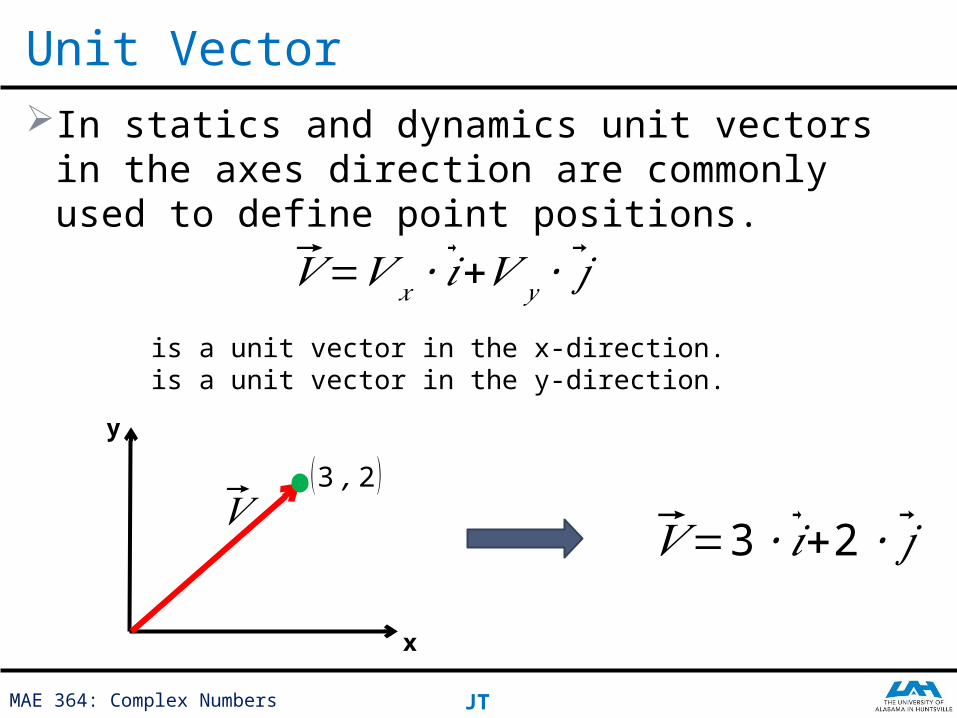
In statics and dynamics unit vectors in the axes direction are commonly used to define point positions.
Unit Vector
𝑉=𝑉 𝑥 ∙ �⃗�+𝑉 𝑦 ∙ �⃗�
is a unit vector in the x-direction. is a unit vector in the y-direction.
(3 ,2 )𝑉
x
y
𝑉=3∙ �⃗�+2 ∙ �⃗�
MAE 364: Complex Numbers JT
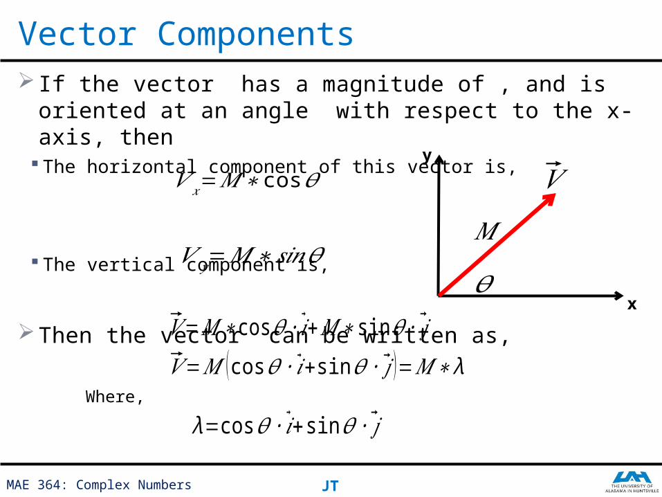
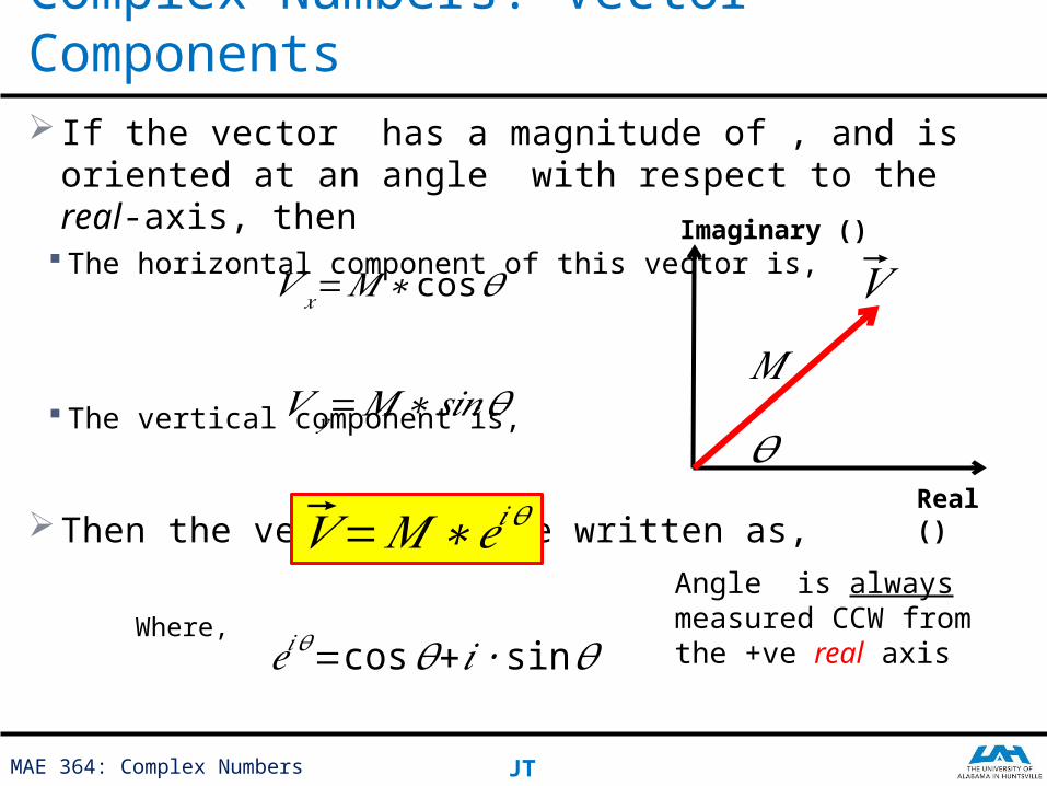
If the vector has a magnitude of , and is oriented at an angle with respect to the x-axis, then
The horizontal component of this vector is,
The vertical component is,
Then the vector can be written as,
Vector Components
𝑉 𝑥=𝑀∗ cos𝜃
𝑉 𝑦=𝑀∗𝑠𝑖𝑛𝜃
𝑉=𝑀∗cos𝜃 ∙ �⃗�+𝑀∗ sin 𝜃 ∙ �⃗�
𝑉=𝑀 (cos𝜃 ∙ �⃗�+sin 𝜃 ∙ �⃗� )=𝑀∗ λWhere,
λ=cos𝜃 ∙ �⃗�+sin 𝜃 ∙ �⃗�
𝑉
x
y
𝑀
𝜃
MAE 364: Complex Numbers JT
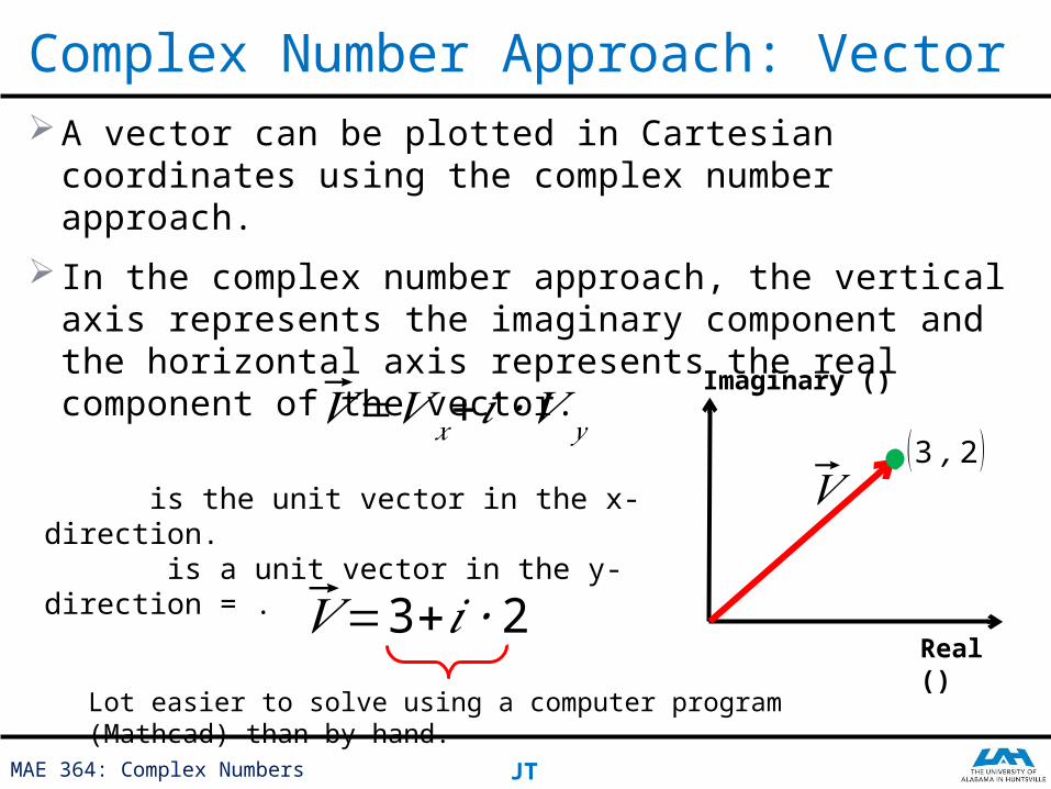
A vector can be plotted in Cartesian coordinates using the complex number approach.
In the complex number approach, the vertical axis represents the imaginary component and the horizontal axis represents the real component of the vector.
Complex Number Approach: Vector
𝑉=𝑉 𝑥+ 𝑖∙𝑉 𝑦
is the unit vector in the x-direction. is a unit vector in the y-direction = .
(3 ,2 )𝑉
Real ()
Imaginary ()
𝑉=3+𝑖 ∙2Lot easier to solve using a computer program (Mathcad) than by hand.
MAE 364: Complex Numbers JT
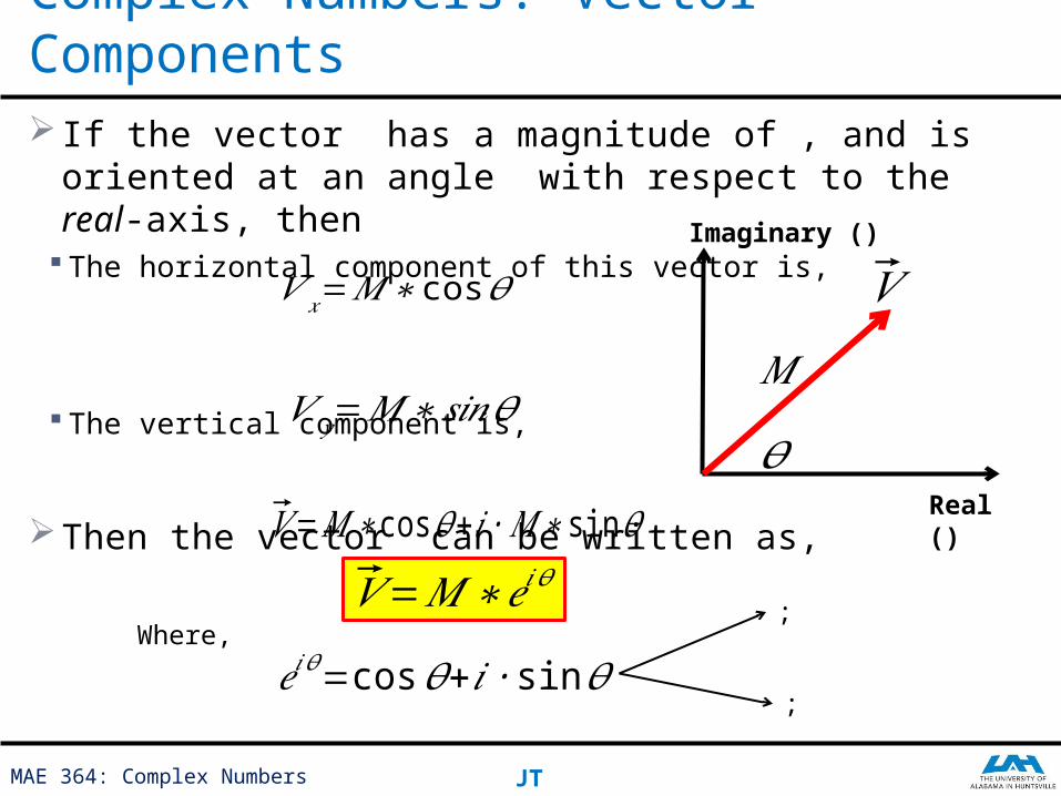
If the vector has a magnitude of , and is oriented at an angle with respect to the real-axis, then
The horizontal component of this vector is,
The vertical component is,
Then the vector can be written as,
Complex Numbers: Vector Components
𝑉 𝑥=𝑀∗ cos𝜃
𝑉 𝑦=𝑀∗𝑠𝑖𝑛𝜃
𝑉=𝑀∗cos𝜃+𝑖∙𝑀∗ sin 𝜃
𝑉=𝑀∗𝑒𝑖 𝜃
Where,
𝑒𝑖𝜃=cos𝜃+𝑖∙ sin 𝜃
𝑉
𝑀
𝜃
Imaginary ()
Real ()
;
;
Using Complex Numbers Approach
Mathematical Analysis of Mechanisms:
MAE 364: Complex Numbers JT
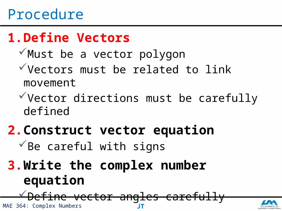
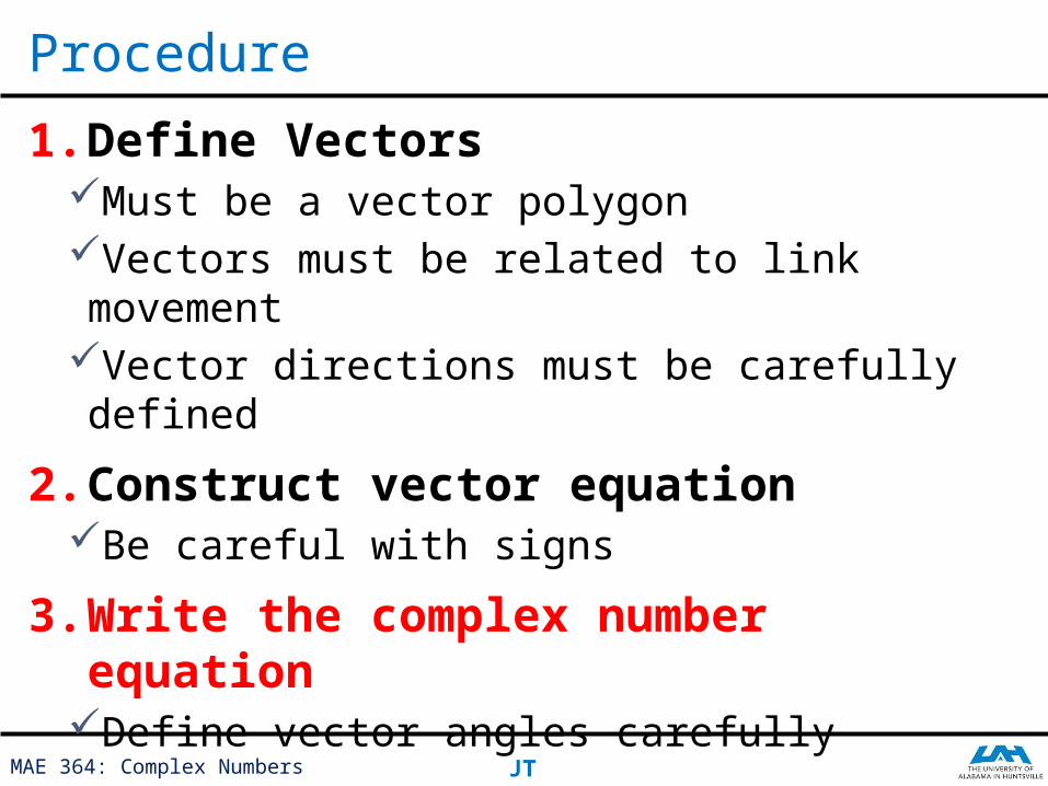
1. Define VectorsMust be a vector polygonVectors must be related to link movementVector directions must be carefully defined
2. Construct vector equationBe careful with signs
3. Write the complex number equationDefine vector angles carefully
Procedure
MAE 364: Complex Numbers JT
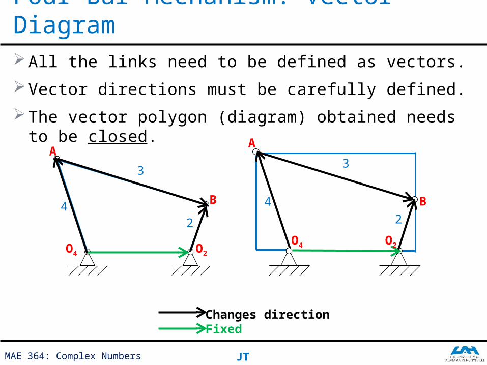
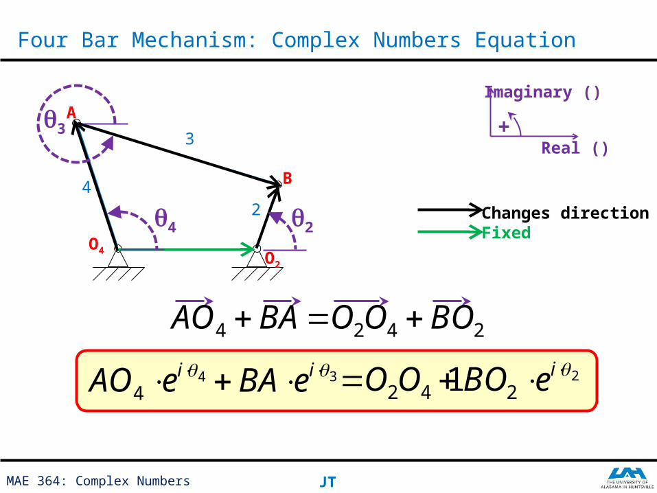
All the links need to be defined as vectors.
Vector directions must be carefully defined.
The vector polygon (diagram) obtained needs to be closed.
Four Bar Mechanism: Vector Diagram
2
3
42
3
4 B
O4
A
O4 O2
B
A
O2
Changes directionFixed
MAE 364: Complex Numbers JT
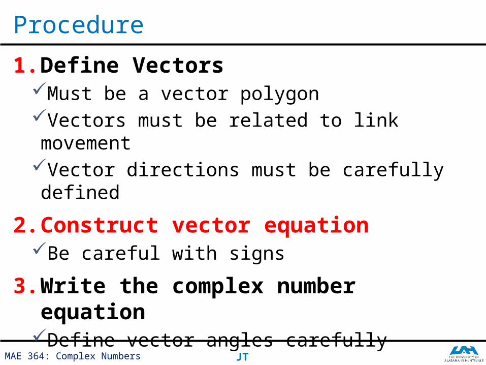
1. Define VectorsMust be a vector polygonVectors must be related to link movementVector directions must be carefully defined
2. Construct vector equationBe careful with signs
3. Write the complex number equationDefine vector angles carefully
Procedure
MAE 364: Complex Numbers JT
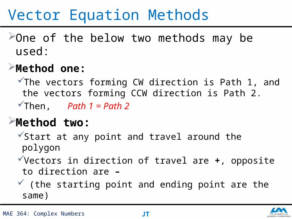
One of the below two methods may be used:Method one:
The vectors forming CW direction is Path 1, and the vectors forming CCW direction is Path 2.
Then, Path 1 = Path 2
Method two:Start at any point and travel around the polygonVectors in direction of travel are +, opposite to direction are –
(the starting point and ending point are the same)
Vector Equation Methods
MAE 364: Complex Numbers JT
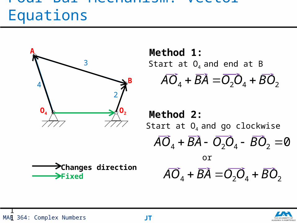
Four Bar Mechanism: Vector Equations
2
3
4
Changes directionFixed
A
O4 O2
B
Method 1:Start at O4 and end at B
2424 BOOOBAAO
Method 2:Start at O4 and go clockwise
02424 BOOOBAAO
2424 BOOOBAAO or
11
MAE 364: Complex Numbers JT
1. Define VectorsMust be a vector polygonVectors must be related to link movementVector directions must be carefully defined
2. Construct vector equationBe careful with signs
3. Write the complex number equationDefine vector angles carefully
Procedure
MAE 364: Complex Numbers JT
If the vector has a magnitude of , and is oriented at an angle with respect to the real-axis, then
The horizontal component of this vector is,
The vertical component is,
Then the vector can be written as,
Complex Numbers: Vector Components
𝑉 𝑥=𝑀∗ cos𝜃
𝑉 𝑦=𝑀∗𝑠𝑖𝑛𝜃
𝑉=𝑀∗𝑒𝑖 𝜃
Where,𝑒𝑖𝜃=cos𝜃+𝑖∙ sin 𝜃
𝑉
𝑀
𝜃
Imaginary ()
Real ()
Angle is always measured CCW from the +ve real axis
MAE 364: Complex Numbers JT
Four Bar Mechanism: Complex Numbers Equation
2
3
4
Changes directionFixed
A
O4O2
B
q2
q3
q4
44
ieAO
2424 BOOOBAAO
3 ieBA 142 OO 22
ieBO
Real ()
Imaginary ()
+
MAE 364: Complex Numbers JT
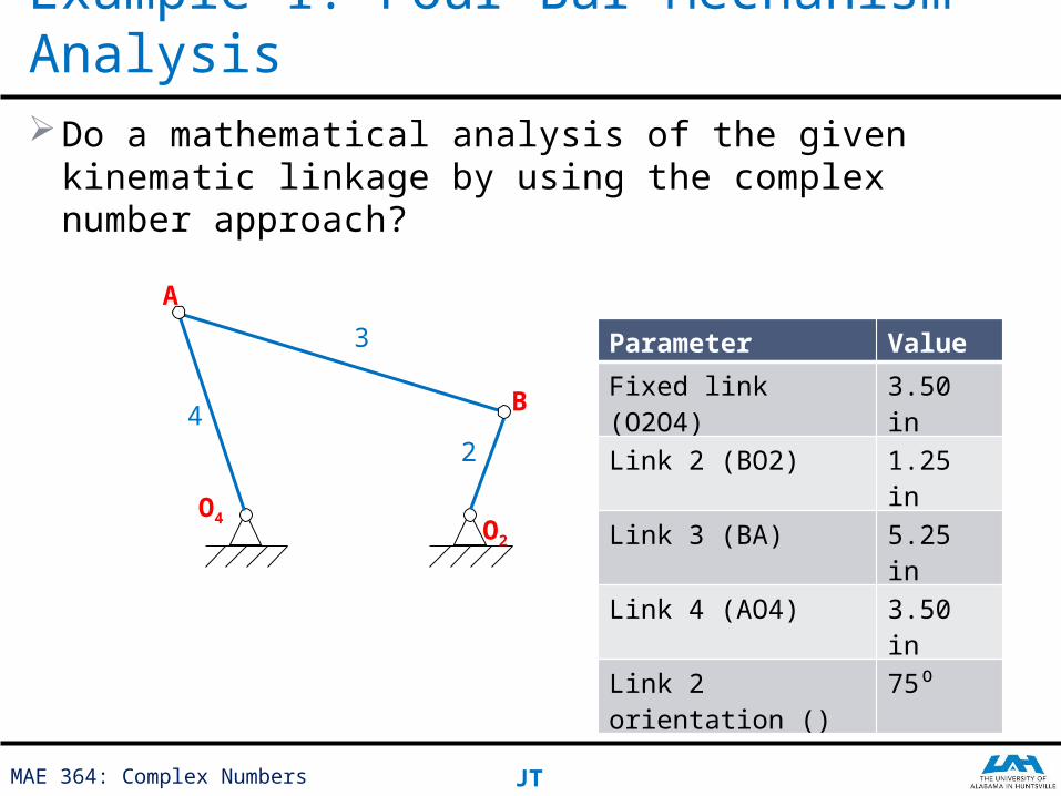
Do a mathematical analysis of the given kinematic linkage by using the complex number approach?
Example 1: Four Bar Mechanism Analysis
2
3
4
A
O4O2
B
Parameter Value
Fixed link (O2O4) 3.50 in
Link 2 (BO2) 1.25 in
Link 3 (BA) 5.25 in
Link 4 (AO4) 3.50 in
Link 2 orientation ()
75⁰

MAE 364: Complex Numbers JT
Solution:
Example 1: Four Bar Mechanism Analysis
2
3
4
A
O4O2
B
Changes directionFixed
Vector Diagram
�⃗�𝑂4+�⃗�𝐴=�⃗�2𝑂4+�⃗�𝑂2
𝐴𝑂4 ∙𝑒𝑖 ∙𝜃4+𝐵𝐴 ∙𝑒𝑖 ∙𝜃3=𝑂2𝑂4+𝐵𝑂2 ∙𝑒
𝑖 ∙𝜃 2
Vector Equation
Complex Number Equation
2
3
4
A
O4O2
B
q2
q3
q4
MAE 364: Complex Numbers JT
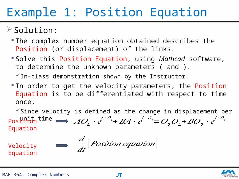
Solution: The complex number equation obtained describes the Position (or
displacement) of the links. Solve this Position Equation, using Mathcad software, to determine the
unknown parameters ( and ).In-class demonstration shown by the Instructor.
In order to get the velocity parameters, the Position Equation is to be differentiated with respect to time once.Since velocity is defined as the change in displacement per unit time.
Example 1: Position Equation
𝐴𝑂4 ∙𝑒𝑖 ∙𝜃4+𝐵𝐴 ∙𝑒𝑖 ∙𝜃3=𝑂2𝑂4+𝐵𝑂2 ∙𝑒
𝑖 ∙𝜃 2Position Equation
Velocity Equation
𝑑𝑑𝑡
[𝑃𝑜𝑠𝑖𝑡𝑖𝑜𝑛𝑒𝑞𝑢𝑎𝑡𝑖𝑜𝑛 ]
MAE 364: Complex Numbers JT
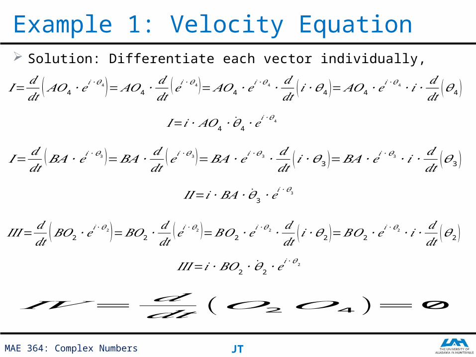
Solution: Differentiate each vector individually,
Example 1: Velocity Equation
𝐼=𝑑𝑑𝑡 ( 𝐴𝑂4 ∙𝑒
𝑖 ∙𝜃4 )=𝐴𝑂4 ∙𝑑𝑑𝑡
(𝑒𝑖 ∙𝜃4 )=𝐴𝑂4 ∙𝑒𝑖 ∙𝜃 4∙
𝑑𝑑𝑡 (𝑖 ∙𝜃4 )=𝐴𝑂4 ∙𝑒
𝑖 ∙𝜃4 ∙ 𝑖 ∙𝑑𝑑𝑡 (𝜃4 )
𝐼=𝑖 ∙ 𝐴𝑂4 ∙ �̇�4 ∙𝑒𝑖 ∙𝜃 4
𝐼=𝑑𝑑𝑡
(𝐵𝐴 ∙𝑒𝑖 ∙𝜃3 )=𝐵𝐴 ∙𝑑𝑑𝑡
(𝑒𝑖 ∙𝜃 3 )=𝐵𝐴 ∙𝑒𝑖 ∙𝜃3 ∙𝑑𝑑𝑡 (𝑖 ∙𝜃3 )=𝐵𝐴 ∙𝑒𝑖 ∙𝜃3 ∙𝑖 ∙
𝑑𝑑𝑡 (𝜃3 )
𝐼𝐼=𝑖∙𝐵𝐴 ∙ �̇�3 ∙𝑒𝑖 ∙𝜃3
𝐼𝐼𝐼=𝑑𝑑𝑡 (𝐵𝑂2 ∙𝑒
𝑖 ∙𝜃2 )=𝐵𝑂2 ∙𝑑𝑑𝑡
(𝑒𝑖 ∙𝜃 2 )=𝐵𝑂2 ∙𝑒𝑖 ∙𝜃2 ∙
𝑑𝑑𝑡 (𝑖 ∙𝜃2)=𝐵𝑂2 ∙𝑒
𝑖 ∙𝜃2 ∙𝑖 ∙𝑑𝑑𝑡 (𝜃2 )
𝐼𝐼𝐼=𝑖 ∙𝐵𝑂2 ∙ �̇�2 ∙𝑒𝑖 ∙𝜃2
𝐼𝑉=𝑑𝑑𝑡 (𝑂2𝑂4 )=0
MAE 364: Complex Numbers JT
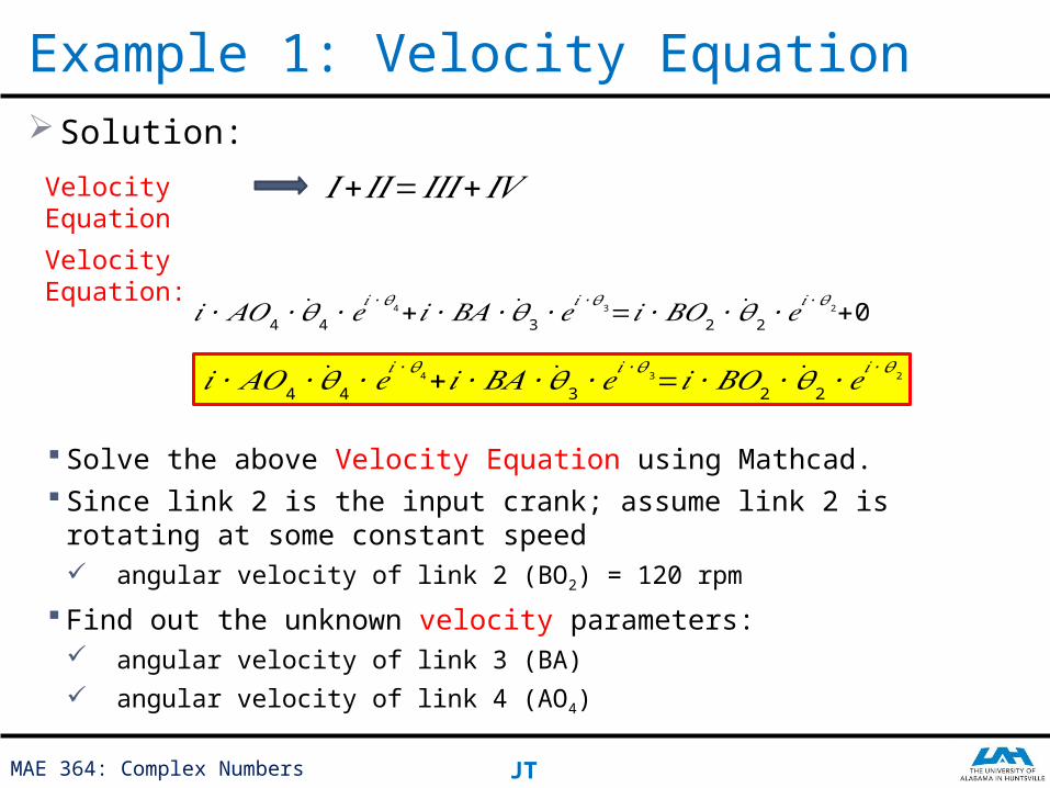
Solution:
Solve the above Velocity Equation using Mathcad. Since link 2 is the input crank; assume link 2 is rotating at some constant
speed angular velocity of link 2 (BO2) = 120 rpm
Find out the unknown velocity parameters: angular velocity of link 3 (BA)
angular velocity of link 4 (AO4)
Example 1: Velocity Equation
Velocity Equation
𝐼+𝐼𝐼=𝐼𝐼𝐼 +𝐼𝑉
Velocity Equation:
𝑖 ∙𝐴𝑂4 ∙ �̇�4 ∙𝑒𝑖 ∙𝜃4+ 𝑖∙𝐵𝐴 ∙ �̇�3 ∙𝑒
𝑖 ∙𝜃3=𝑖∙𝐵𝑂2 ∙ �̇�2 ∙𝑒𝑖 ∙𝜃2+0
𝑖 ∙𝐴𝑂4 ∙ �̇�4 ∙𝑒𝑖 ∙𝜃4+ 𝑖∙𝐵𝐴 ∙ �̇�3 ∙𝑒
𝑖 ∙𝜃3=𝑖∙𝐵𝑂2 ∙ �̇�2∙𝑒𝑖 ∙𝜃2
MAE 364: Complex Numbers JT
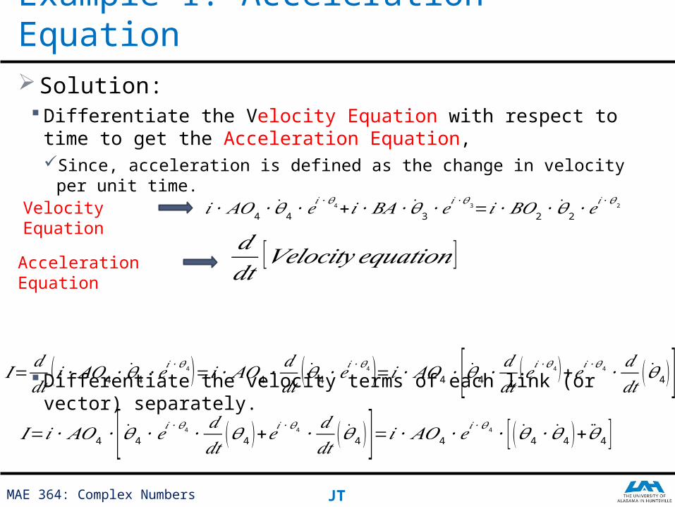
Solution: Differentiate the Velocity Equation with respect to time to get the
Acceleration Equation,Since, acceleration is defined as the change in velocity per unit time.
Differentiate the velocity terms of each link (or vector) separately.
Example 1: Acceleration Equation
Velocity Equation
𝑖 ∙𝐴𝑂4 ∙ �̇�4 ∙𝑒𝑖 ∙𝜃4+ 𝑖∙𝐵𝐴 ∙ �̇�3 ∙𝑒
𝑖 ∙𝜃3=𝑖∙𝐵𝑂2 ∙ �̇�2 ∙𝑒𝑖 ∙𝜃2
Acceleration Equation
𝑑𝑑𝑡
[𝑉𝑒𝑙𝑜𝑐𝑖𝑡𝑦 𝑒𝑞𝑢𝑎𝑡𝑖𝑜𝑛 ]
𝐼= 𝑑𝑑𝑡
( 𝑖 ∙𝐴𝑂4 ∙ �̇�4 ∙𝑒𝑖 ∙𝜃4 )=𝑖∙ 𝐴𝑂4 ∙
𝑑𝑑𝑡
( �̇�4 ∙𝑒𝑖 ∙𝜃4 )=𝑖 ∙𝐴𝑂4 ∙[�̇�4 ∙ 𝑑𝑑𝑡 (𝑒𝑖 ∙𝜃4 )+𝑒𝑖 ∙𝜃4 ∙𝑑𝑑𝑡 ( �̇�4 )]
𝐼=𝑖 ∙ 𝐴𝑂4 ∙[ �̇�4 ∙𝑒𝑖 ∙𝜃4 ∙𝑑𝑑𝑡 (𝜃4 )+𝑒𝑖 ∙𝜃4 ∙
𝑑𝑑𝑡 ( �̇�4 )]=𝑖 ∙𝐴𝑂4 ∙𝑒
𝑖 ∙𝜃 4∙ [( �̇�4 ∙ �̇�4 )+�̈�4 ]
MAE 364: Complex Numbers JT
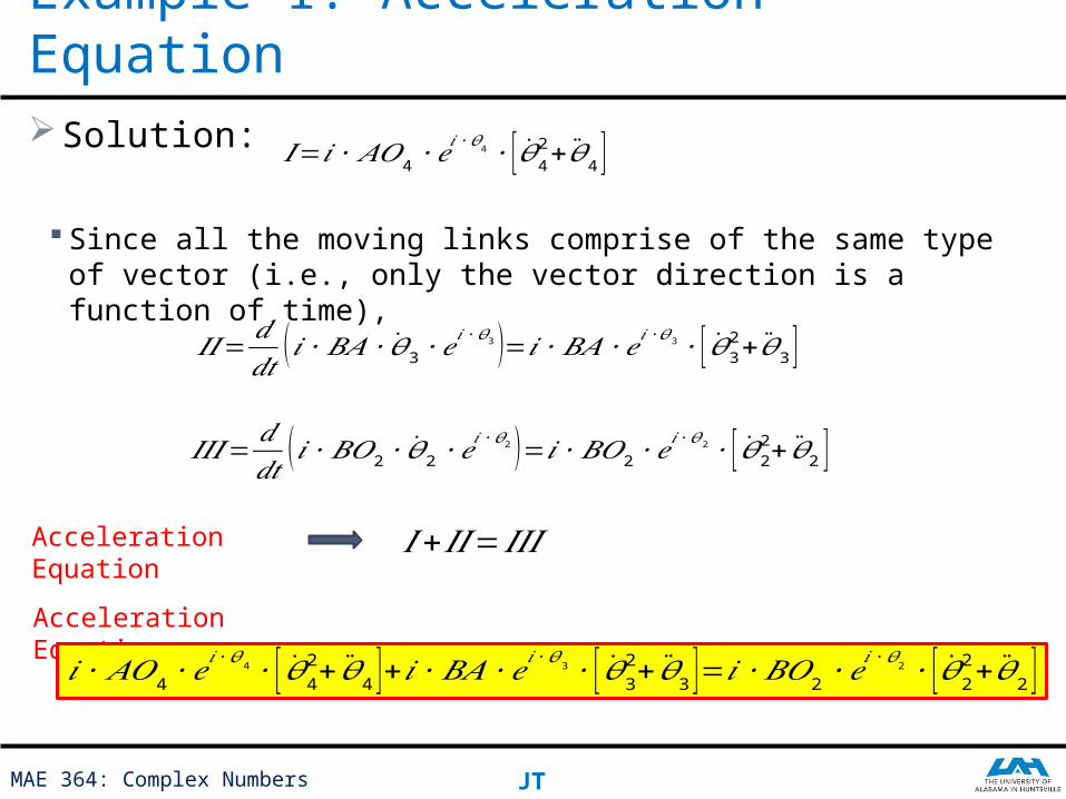
Solution:
Since all the moving links comprise of the same type of vector (i.e., only the vector direction is a function of time),
Example 1: Acceleration Equation
𝐼=𝑖 ∙ 𝐴𝑂4 ∙𝑒𝑖 ∙𝜃 4 ∙ [ �̇�42+ �̈�4 ]
𝐼𝐼=𝑑𝑑𝑡 (𝑖 ∙𝐵𝐴 ∙ �̇�3 ∙𝑒𝑖 ∙𝜃 3 )=𝑖 ∙𝐵𝐴 ∙𝑒𝑖 ∙𝜃3 ∙ [ �̇�32+�̈�3 ]
𝐼𝐼𝐼=𝑑𝑑𝑡 ( 𝑖∙𝐵𝑂2 ∙ �̇�2 ∙𝑒
𝑖 ∙𝜃 2 )=𝑖 ∙𝐵𝑂2 ∙𝑒𝑖 ∙𝜃2 ∙ [ �̇�22+ �̈�2 ]
Acceleration Equation
𝐼+𝐼𝐼=𝐼𝐼𝐼
Acceleration Equation:𝑖 ∙𝐴𝑂4 ∙𝑒
𝑖 ∙𝜃 4∙ [ �̇�42+ �̈�4 ]+𝑖 ∙𝐵𝐴 ∙𝑒𝑖 ∙𝜃3 ∙ [�̇�32+ �̈�3 ]=𝑖 ∙𝐵𝑂2 ∙𝑒𝑖 ∙𝜃2 ∙ [ �̇�22+ �̈�2 ]
MAE 364: Complex Numbers JT
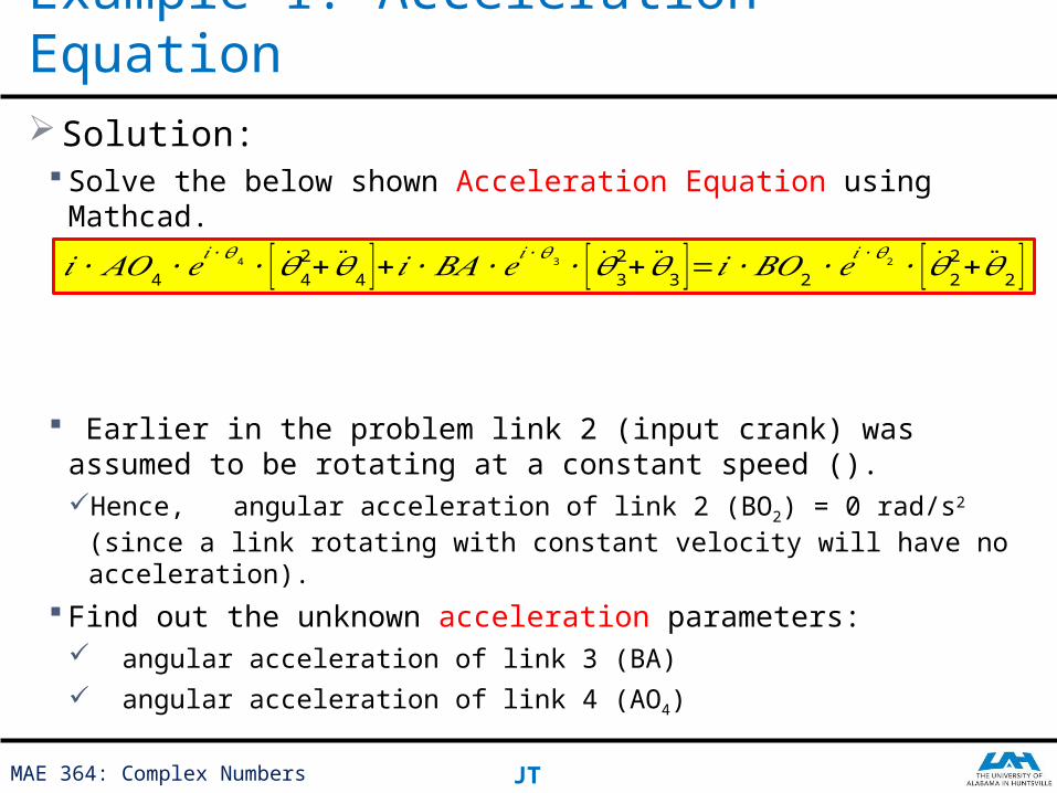
Solution: Solve the below shown Acceleration Equation using Mathcad.
Earlier in the problem link 2 (input crank) was assumed to be rotating at a constant speed (). Hence, angular acceleration of link 2 (BO2) = 0 rad/s2 (since a link rotating with
constant velocity will have no acceleration).
Find out the unknown acceleration parameters: angular acceleration of link 3 (BA)
angular acceleration of link 4 (AO4)
Example 1: Acceleration Equation
𝑖 ∙𝐴𝑂4 ∙𝑒𝑖 ∙𝜃 4∙ [ �̇�42+ �̈�4 ]+𝑖 ∙𝐵𝐴 ∙𝑒𝑖 ∙𝜃3 ∙ [�̇�32+ �̈�3 ]=𝑖 ∙𝐵𝑂2 ∙𝑒
𝑖 ∙𝜃2 ∙ [ �̇�22+ �̈�2 ]
With lower pair joints (revolute & prismatic)
Mechanisms
MAE 364: Complex Numbers JT
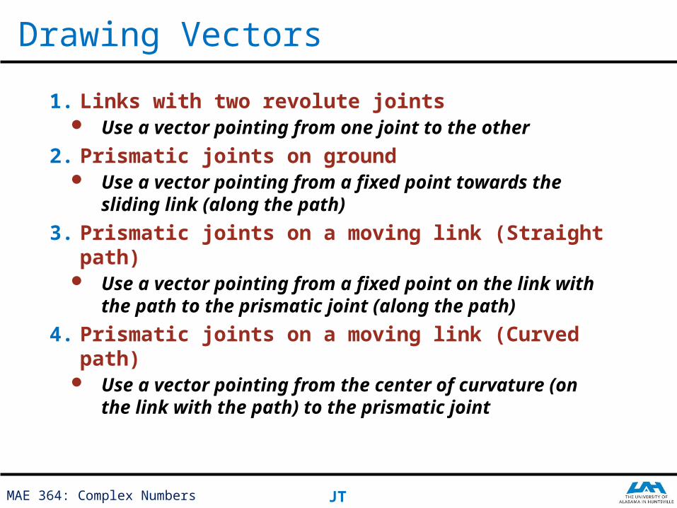
Drawing Vectors
1. Links with two revolute joints Use a vector pointing from one joint to the other
2. Prismatic joints on ground Use a vector pointing from a fixed point towards
the sliding link (along the path)
3. Prismatic joints on a moving link (Straight path)
Use a vector pointing from a fixed point on the link with the path to the prismatic joint (along the path)
4. Prismatic joints on a moving link (Curved path) Use a vector pointing from the center of
curvature (on the link with the path) to the prismatic joint
MAE 364: Complex Numbers JT
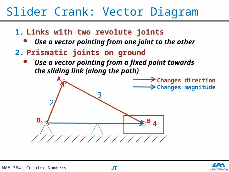
Slider Crank: Vector Diagram
23
4
1. Links with two revolute joints Use a vector pointing from one joint to the
other
2. Prismatic joints on ground Use a vector pointing from a fixed point
towards the sliding link (along the path)Changes directionChanges magnitude
O2 B
A
MAE 364: Complex Numbers JT
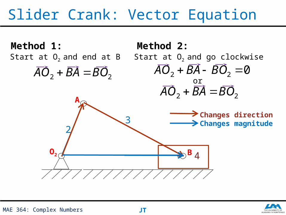
Slider Crank: Vector Equation
23
4
Changes directionChanges magnitude
O2 B
A
Method 1:Start at O2 and end at B
22 BOBAAO
Method 2:Start at O2 and go clockwise
or022 BOBAAO
22 BOBAAO
MAE 364: Complex Numbers JT
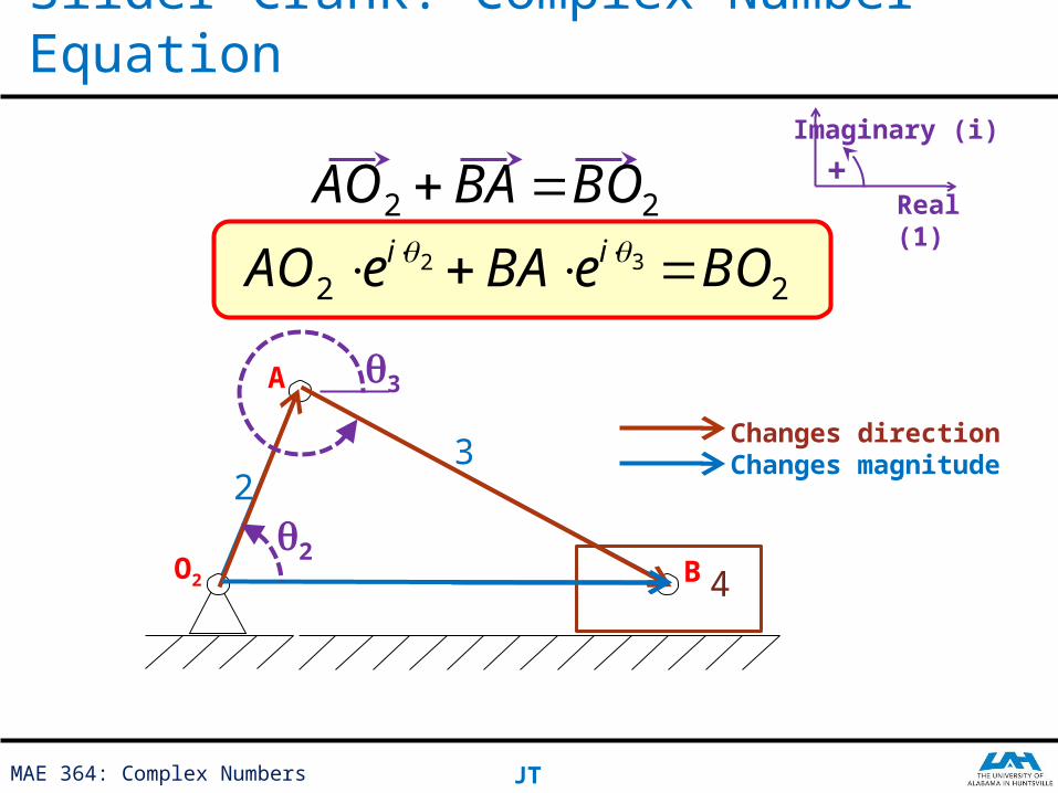
Slider Crank: Complex Number Equation
Real (1)
Imaginary (i)
+
23
4
Changes directionChanges magnitude
O2 B
A
22 BOBAAO
q2
q3
22
ieAO 2BO3 ieBA
MAE 364: Complex Numbers JT
Offset Slider Crank: Vector Diagram
2
3
4
1. Links with two revolute joints Use a vector pointing from one joint to the
other
2. Prismatic joints on ground Use a vector pointing from a fixed point
towards the sliding link (along the path)Changes directionChanges magnitudeFixed
Want the vectors on link 1 to be perpendicular
O2
B
A

MAE 364: Complex Numbers JT
Offset Slider Crank: Vector Equation
2
3
4
Changes directionChanges magnitudeFixed
Want the vectors on link 1 to be perpendicular
O2
B
A
Method 1:Start at O2 and end at B
BCCOBAAO 22
Method 2:Start at O2 and go clockwise
or
C
BCCOBAAO 22
022 BCCOBAAO
MAE 364: Complex Numbers JT
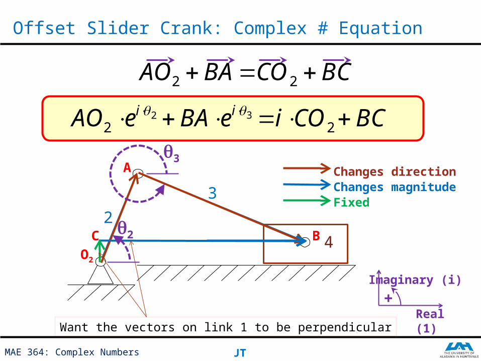
Offset Slider Crank: Complex # Equation
2
3
4
Changes directionChanges magnitudeFixed
Want the vectors on link 1 to be perpendicular
O2
B
A
BCCOBAAO 22
C
22
ieAOq3
q2
2COi BC3 ieBA
Real (1)
Imaginary (i)
+
MAE 364: Complex Numbers JT
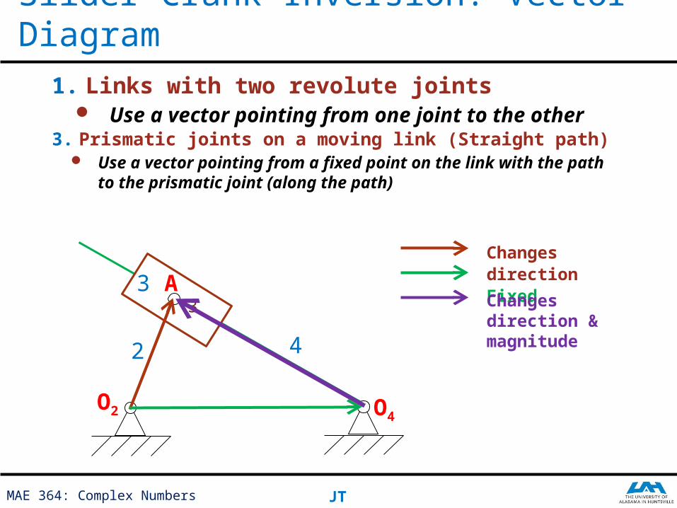
Slider Crank Inversion: Vector Diagram1. Links with two revolute joints
Use a vector pointing from one joint to the other
Changes directionFixed
3
3. Prismatic joints on a moving link (Straight path) Use a vector pointing from a fixed point on the link
with the path to the prismatic joint (along the path)
Changes direction & magnitude
O2
O4
A
2
3
4
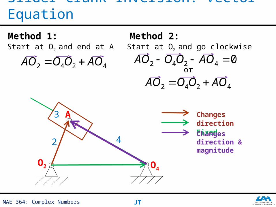
MAE 364: Complex Numbers JT
Slider Crank Inversion: Vector Equation
Changes directionFixed
3Changes direction & magnitude
O2
O4
A
2
3
4
Method 1:Start at O2 and end at A
4242 AOOOAO
Method 2:Start at O2 and go clockwise
or
4242 AOOOAO
04242 AOOOAO
MAE 364: Complex Numbers JT
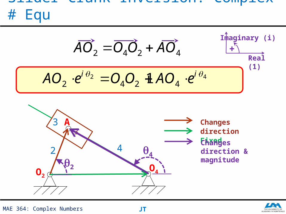
Slider Crank Inversion: Complex # Equ
Real (1)
Imaginary (i)
+
Changes directionFixed
3
Changes direction & magnitude
O2
O4
A
2
3
4
4242 AOOOAO
22
ieAO
q4q
2
124 OO 44
ieAO
MAE 364: Complex Numbers JT
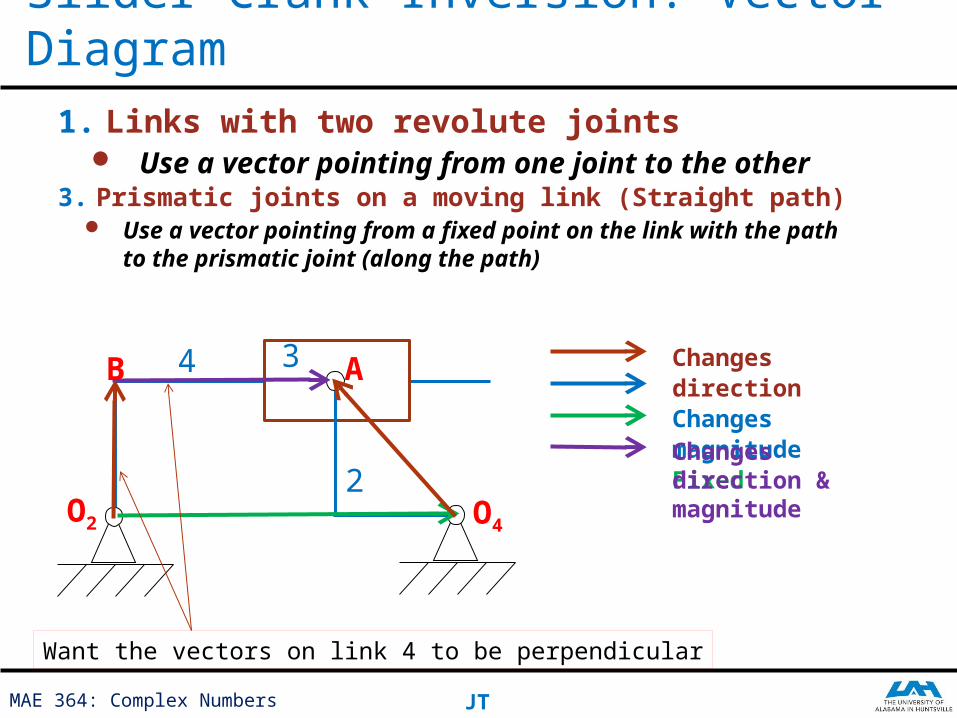
Slider Crank Inversion: Vector Diagram1. Links with two revolute joints
Use a vector pointing from one joint to the other
Changes directionChanges magnitudeFixed
3. Prismatic joints on a moving link (Straight path) Use a vector pointing from a fixed point on the link
with the path to the prismatic joint (along the path)
Changes direction & magnitude
Want the vectors on link 4 to be perpendicular
O2
O4
AB 4 3
2
MAE 364: Complex Numbers JT
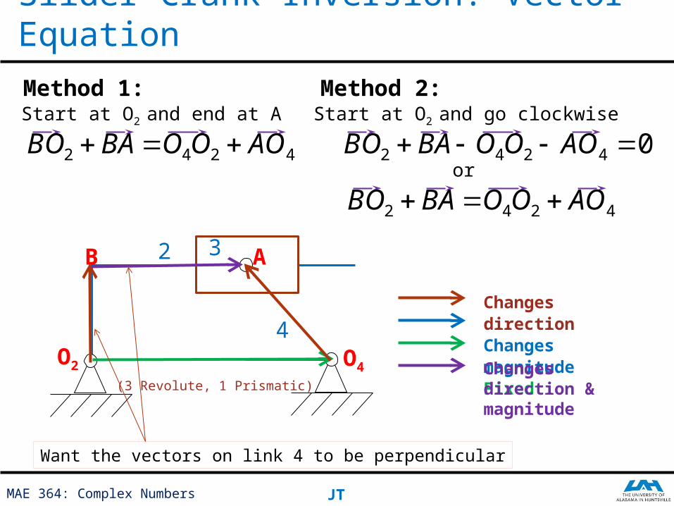
Slider Crank Inversion: Vector Equation
(3 Revolute, 1 Prismatic)
Changes directionChanges magnitudeFixedChanges direction & magnitude
Want the vectors on link 4 to be perpendicular
O2
O4
AB
4
32
Method 1:Start at O2 and end at A
4242 AOOOBABO
Method 2:Start at O2 and go clockwise
or
4242 AOOOBABO
04242 AOOOBABO
MAE 364: Complex Numbers JT
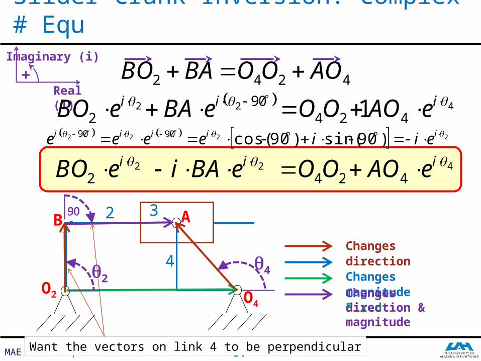
Slider Crank Inversion: Complex # Equ
Want the vectors on link 4 to be perpendicular
O2
O4
AB
4
32
124 OO
q4
q2
4242 AOOOBABO 2
2 ieBO 902ieBA 4
4 ieAO
2222 )90sin()90cos(9090 iiiii eiieeee
124 OO22
ieBO 2 ieBAi 44
ieAO
90°
Changes directionChanges magnitudeFixedChanges direction & magnitude
Real (1)
Imaginary (i)
+
MAE 364: Complex Numbers JT
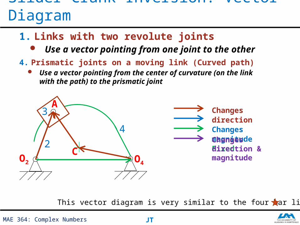
Slider Crank Inversion: Vector Diagram1. Links with two revolute joints
Use a vector pointing from one joint to the other
Changes directionChanges magnitudeFixedChanges direction & magnitude
4. Prismatic joints on a moving link (Curved path) Use a vector pointing from the center of curvature
(on the link with the path) to the prismatic joint
This vector diagram is very similar to the four bar linkage
O2
O4
A
C
3
2
4
MAE 364: Complex Numbers JT
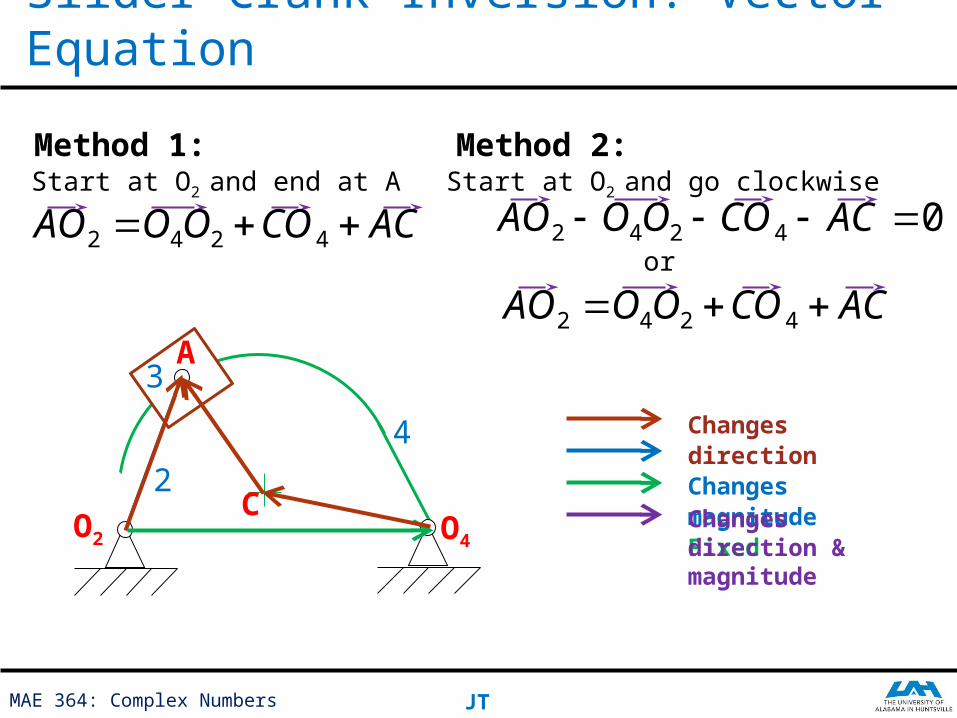
Slider Crank Inversion: Vector Equation
Changes directionChanges magnitudeFixedChanges direction & magnitude
O2
O4
A
C
3
2
4
Method 1:Start at O2 and end at A
ACCOOOAO 4242
Method 2:Start at O2 and go clockwise
or
ACCOOOAO 4242
04242 ACCOOOAO
MAE 364: Complex Numbers JT
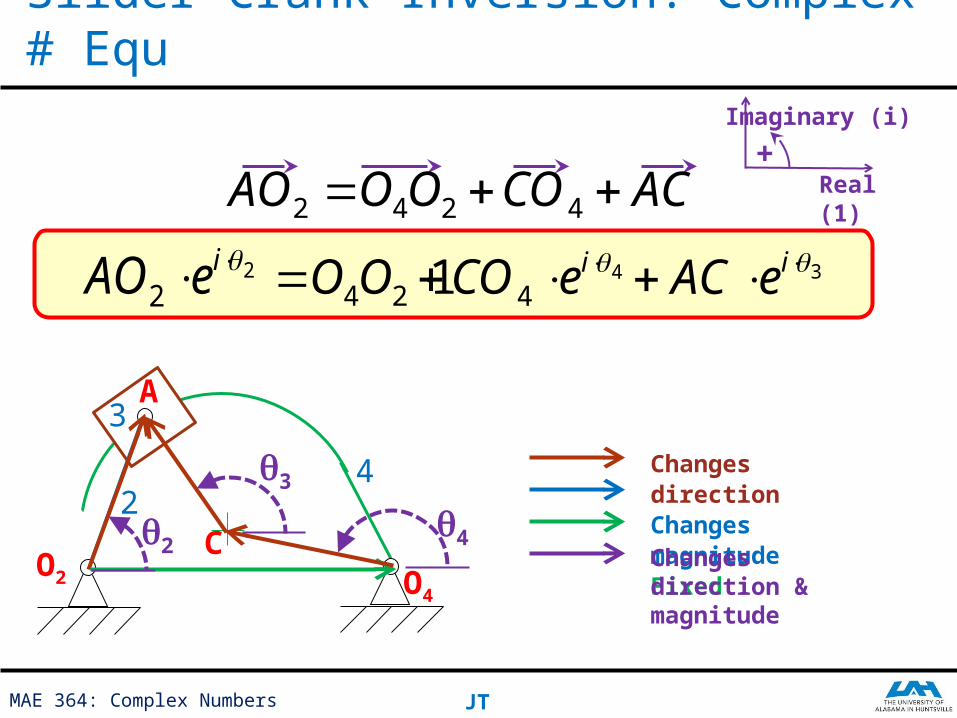
Slider Crank Inversion: Complex # Equ
Changes directionChanges magnitudeFixedChanges direction & magnitude
O2
O4
A
C
3
24
ACCOOOAO 4242
22
ieAO
q4
q2
q3
124 OO 3 ieAC44
ieCO
Real (1)
Imaginary (i)
+
MAE 364: Complex Numbers JT
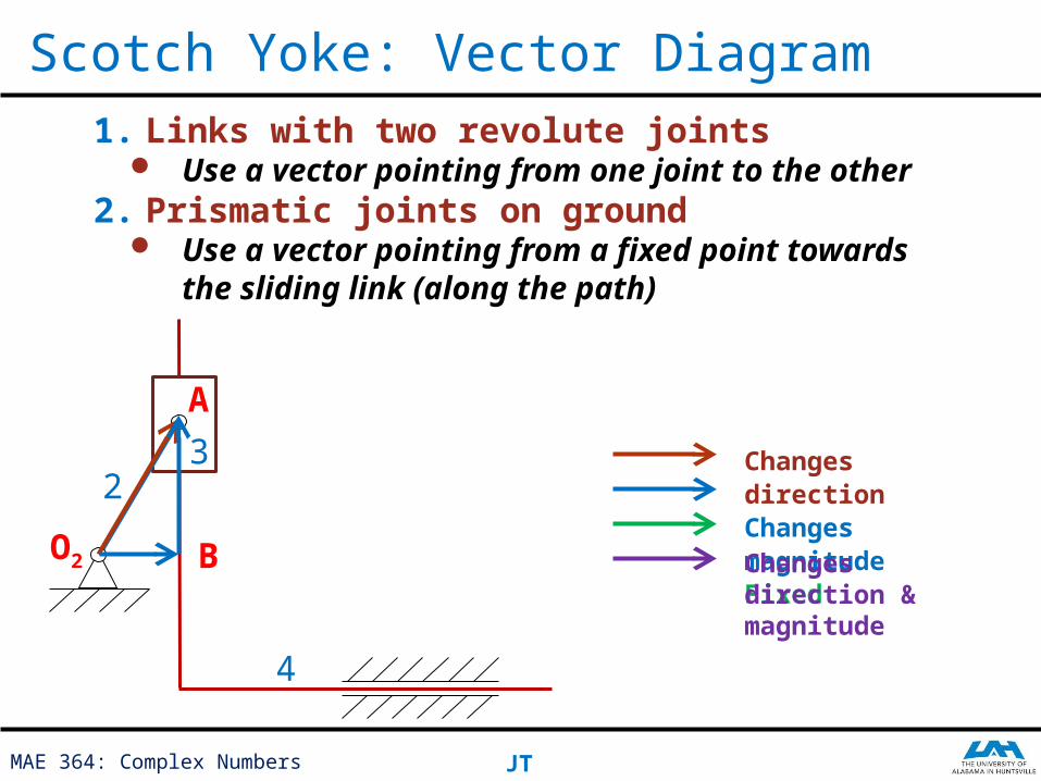
Scotch Yoke: Vector Diagram
Changes directionChanges magnitudeFixedChanges direction & magnitude
1. Links with two revolute joints Use a vector pointing from one joint to the
other2. Prismatic joints on ground
Use a vector pointing from a fixed point towards the sliding link (along the path)
A
B
32
4
O2
MAE 364: Complex Numbers JT
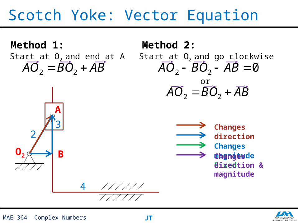
Scotch Yoke: Vector Equation
Changes directionChanges magnitudeFixedChanges direction & magnitude
A
B
32
4
O2
Method 1:Start at O2 and end at A
ABBOAO 22
Method 2:Start at O2 and go clockwise
or
ABBOAO 22
022 ABBOAO
MAE 364: Complex Numbers JT
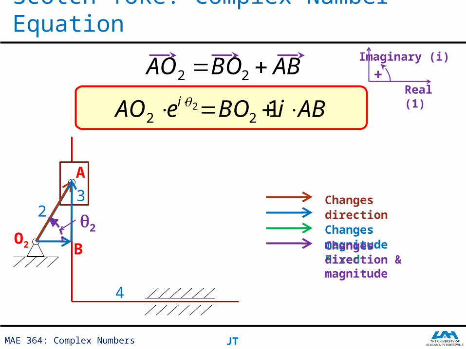
Scotch Yoke: Complex Number Equation
Changes directionChanges magnitudeFixedChanges direction & magnitude
A
B
32
4
O2
ABBOAO 22
22
ieAO
q2
12 BO ABiReal (1)
Imaginary (i)
+
MAE 364: Complex Numbers JT
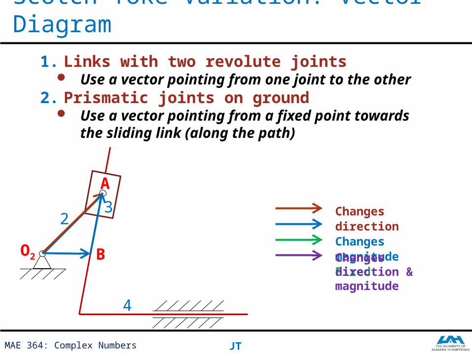
Scotch Yoke Variation: Vector Diagram
Changes directionChanges magnitudeFixedChanges direction & magnitude
1. Links with two revolute joints Use a vector pointing from one joint to the
other2. Prismatic joints on ground
Use a vector pointing from a fixed point towards the sliding link (along the path)
A
B
32
4
O2
MAE 364: Complex Numbers JT
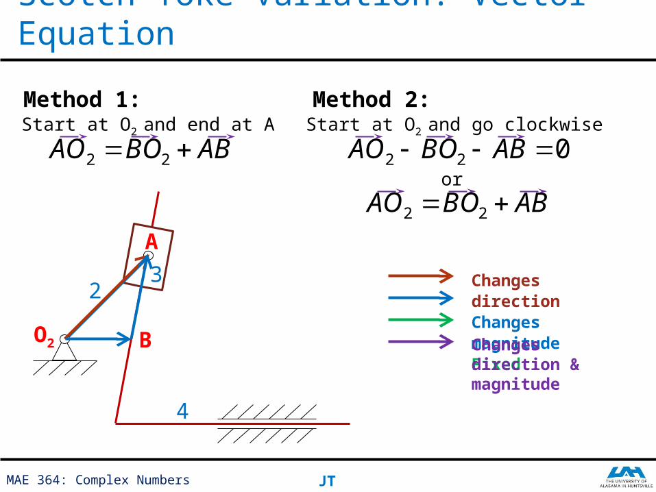
Scotch Yoke Variation: Vector Equation
Changes directionChanges magnitudeFixedChanges direction & magnitude
A
B
32
4
O2
Method 1:Start at O2 and end at A
ABBOAO 22
Method 2:Start at O2 and go clockwise
or
ABBOAO 22
022 ABBOAO
MAE 364: Complex Numbers JT
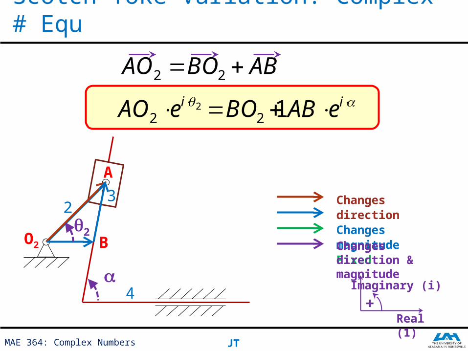
Scotch Yoke Variation: Complex # Equ
12 BO
Changes directionChanges magnitudeFixedChanges direction & magnitude
A
B
32
4
O2
ABBOAO 22
22
ieAO
a
q2
ieAB
Real (1)
Imaginary (i)
+
With higher pair joints (direct contact)
Mechanisms