GOVERNMENT OF INDIA MINISTRY OF INFORMATION AND BROADCASTING · · 2016-06-30Ministry of...
31
1 No. 402-101/2012-CRS (Pt.-1) GOVERNMENT OF INDIA MINISTRY OF INFORMATION AND BROADCASTING LIST OF COMMUNITY RADIO EQUIPMENT TO BE SUPPORTED UNDER THE PLAN SCHEME “SUPPORTING COMMUNITY RADIO MOVEMENT IN INDIA” AND THEIR SPECIFICATIONS/BENCHMARKS NEW DELHI: DECEMBER 16, 2013 MINISTRY OF INFORMATION AND BROADCASTING „A‟ WING, SHASTRI BHAWAN, NEW DELHI-110001
Transcript of GOVERNMENT OF INDIA MINISTRY OF INFORMATION AND BROADCASTING · · 2016-06-30Ministry of...
1
No. 402-101/2012-CRS (Pt.-1)
GOVERNMENT OF INDIA
MINISTRY OF INFORMATION AND BROADCASTING
LIST OF COMMUNITY RADIO EQUIPMENT
TO BE SUPPORTED UNDER THE PLAN SCHEME
“SUPPORTING COMMUNITY RADIO MOVEMENT IN INDIA”
AND THEIR SPECIFICATIONS/BENCHMARKS
NEW DELHI: DECEMBER 16, 2013
MINISTRY OF INFORMATION AND BROADCASTING
„A‟ WING, SHASTRI BHAWAN,
NEW DELHI-110001
2
Ministry of Information and Broadcasting has introduced a new scheme namely
“Supporting Community Radio Movement in India” in the 12th
five year Plan for providing financial
support to new and existing Community Radio Stations under the component “Community Radio
Support Scheme” (CRSS) mainly for equipment acquisition etc. Financial support will be
provided only for those equipment which adhere to benchmarks provided by the Ministry to
ensure quality. The maximum support in the current FYP will be 50% of the total estimated
expenditure, subject to a ceiling of Rs. 7.50 lakhs.
2. In order to shortlist equipment essential for operating a Community Radio Station and to
lay down benchmarks for each shortlisted equipment, a Technical Committee was constituted in
the Ministry under the Chairmanship of Sh. V.K. Singla, Retired Engineer-in-Chief, All India
Radio. The committee consists members from WPC Wing, Department of Electronics,
operational community radio stations, community radio associations and International
Organizations.
3. After detailed discussions and visit to operational stations, the committee has shortlisted
equipment essential for operating CRS and has laid down benchmarks/specifications for each
shortlisted item. The specifications have been made in view that these will generate multi vendor
response for better competition. It is proposed to bring the shortlisted equipment with
specifications/benchmarks in public domain to obtain comments/remarks from stakeholders for
transparency. The list of shortlisted equipment and their specifications are attached.
4. Written comments on the specifications are invited from stakeholders, operational
community radio stations and vendors/equipment suppliers by 31st December 2013. The
comments may be sent, preferably in electronic form to Mr. Inderjeet Grewal, Deputy Director
(CRS), Ministry of Information and Broadcasting, on the e-mail: [email protected]. Hard copy
of comments may be addressed to Deputy Director (CRS), Ministry of Information and
Broadcasting, Room No. 116, „A‟ Wing, Shastri Bhawan, New Delhi. For any
clarification/information, Mr. Inderjeet Grewal, Deputy Director (CRS) may be contacted at Tel.
No.: +91-11-23386547/23385021.
3
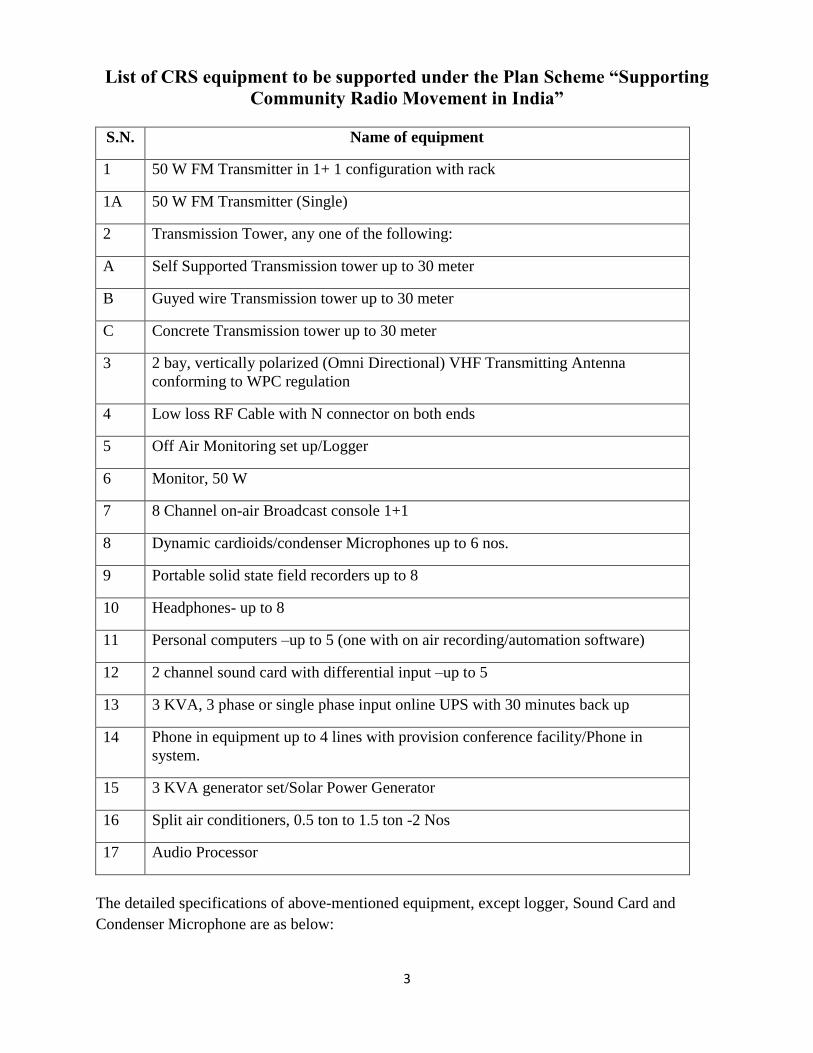
List of CRS equipment to be supported under the Plan Scheme “Supporting
Community Radio Movement in India”
S.N. Name of equipment
1 50 W FM Transmitter in 1+ 1 configuration with rack
1A 50 W FM Transmitter (Single)
2 Transmission Tower, any one of the following:
A Self Supported Transmission tower up to 30 meter
B Guyed wire Transmission tower up to 30 meter
C Concrete Transmission tower up to 30 meter
3 2 bay, vertically polarized (Omni Directional) VHF Transmitting Antenna
conforming to WPC regulation
4 Low loss RF Cable with N connector on both ends
5 Off Air Monitoring set up/Logger
6 Monitor, 50 W
7 8 Channel on-air Broadcast console 1+1
8 Dynamic cardioids/condenser Microphones up to 6 nos.
9 Portable solid state field recorders up to 8
10 Headphones- up to 8
11 Personal computers –up to 5 (one with on air recording/automation software)
12 2 channel sound card with differential input –up to 5
13 3 KVA, 3 phase or single phase input online UPS with 30 minutes back up
14 Phone in equipment up to 4 lines with provision conference facility/Phone in
system.
15 3 KVA generator set/Solar Power Generator
16 Split air conditioners, 0.5 ton to 1.5 ton -2 Nos
17 Audio Processor
The detailed specifications of above-mentioned equipment, except logger, Sound Card and
Condenser Microphone are as below:
4
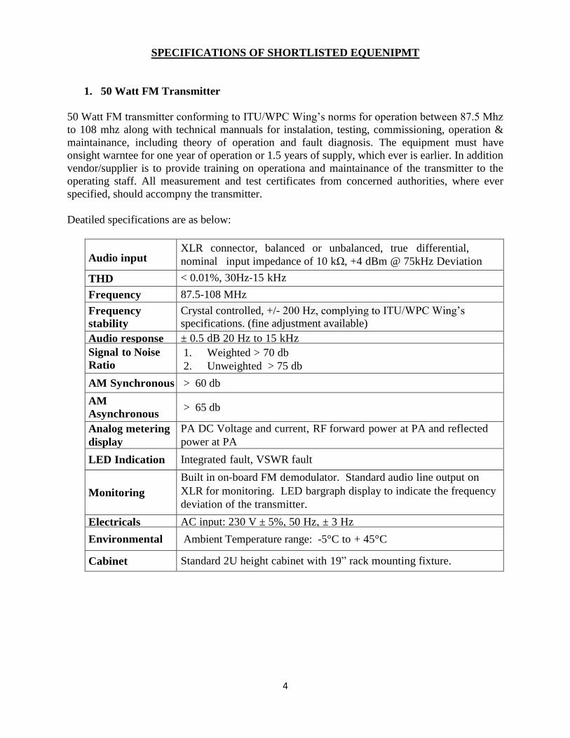
SPECIFICATIONS OF SHORTLISTED EQUENIPMT
1. 50 Watt FM Transmitter
50 Watt FM transmitter conforming to ITU/WPC Wing‟s norms for operation between 87.5 Mhz
to 108 mhz along with technical mannuals for instalation, testing, commissioning, operation &
maintainance, including theory of operation and fault diagnosis. The equipment must have
onsight warntee for one year of operation or 1.5 years of supply, which ever is earlier. In addition
vendor/supplier is to provide training on operationa and maintainance of the transmitter to the
operating staff. All measurement and test certificates from concerned authorities, where ever
specified, should accompny the transmitter.
Deatiled specifications are as below:
Audio input
XLR connector, balanced or unbalanced, true differential,
nominal input impedance of 10 kΩ, +4 dBm @ 75kHz Deviation
THD < 0.01%, 30Hz‐15 kHz
Frequency 87.5-108 MHz
Frequency
stability
Crystal controlled, +/- 200 Hz, complying to ITU/WPC Wing‟s
specifications. (fine adjustment available)
Audio response ± 0.5 dB 20 Hz to 15 kHz
Signal to Noise
Ratio 1. Weighted > 70 db
2. Unweighted > 75 db
AM Synchronous > 60 db
AM
Asynchronous > 65 db
Analog metering
display
PA DC Voltage and current, RF forward power at PA and reflected
power at PA
LED Indication Integrated fault, VSWR fault
Monitoring
Built in on‐board FM demodulator. Standard audio line output on
XLR for monitoring. LED bargraph display to indicate the frequency
deviation of the transmitter.
Electricals AC input: 230 V ± 5%, 50 Hz, ± 3 Hz
Environmental Ambient Temperature range: -5°C to + 45°C
Cabinet Standard 2U height cabinet with 19” rack mounting fixture.
5
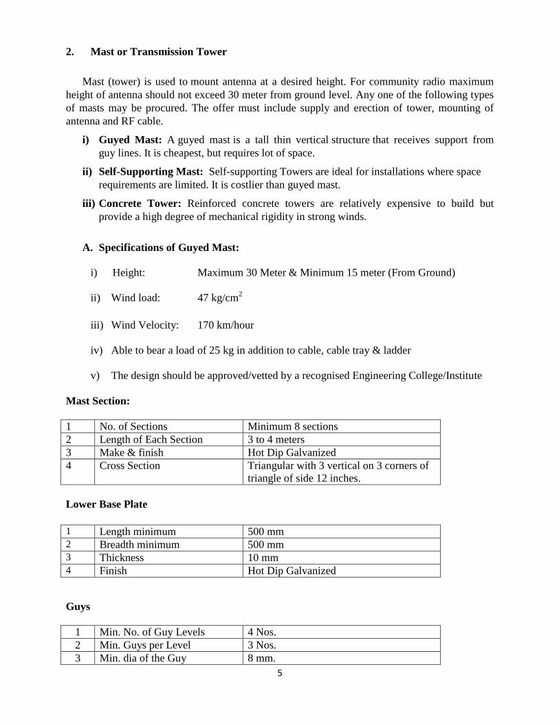
2. Mast or Transmission Tower
Mast (tower) is used to mount antenna at a desired height. For community radio maximum
height of antenna should not exceed 30 meter from ground level. Any one of the following types
of masts may be procured. The offer must include supply and erection of tower, mounting of
antenna and RF cable.
i) Guyed Mast: A guyed mast is a tall thin vertical structure that receives support from
guy lines. It is cheapest, but requires lot of space.
ii) Self-Supporting Mast: Self-supporting Towers are ideal for installations where space
requirements are limited. It is costlier than guyed mast.
iii) Concrete Tower: Reinforced concrete towers are relatively expensive to build but
provide a high degree of mechanical rigidity in strong winds.
A. Specifications of Guyed Mast:
i) Height: Maximum 30 Meter & Minimum 15 meter (From Ground)
ii) Wind load: 47 kg/cm2
iii) Wind Velocity: 170 km/hour
iv) Able to bear a load of 25 kg in addition to cable, cable tray & ladder
v) The design should be approved/vetted by a recognised Engineering College/Institute
Mast Section:
1 No. of Sections Minimum 8 sections
2 Length of Each Section 3 to 4 meters
3 Make & finish Hot Dip Galvanized
4 Cross Section Triangular with 3 vertical on 3 corners of
triangle of side 12 inches.
Lower Base Plate
1 Length minimum 500 mm 2 Breadth minimum 500 mm 3 Thickness 10 mm 4 Finish Hot Dip Galvanized
Guys
1 Min. No. of Guy Levels 4 Nos.
2 Min. Guys per Level 3 Nos.
3 Min. dia of the Guy 8 mm.
6
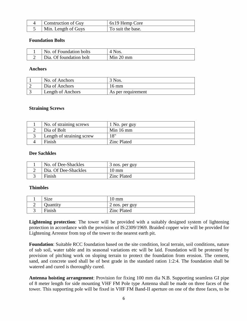
4 Construction of Guy 6x19 Hemp Core
5 Min. Length of Guys To suit the base.
Foundation Bolts
1 No. of Foundation bolts 4 Nos.
2 Dia. Of foundation bolt Min 20 mm
Anchors
1 No. of Anchors 3 Nos.
2 Dia of Anchors 16 mm
3 Length of Anchors As per requirement
Straining Screws
1 No. of straining screws 1 No. per guy
2 Dia of Bolt Min 16 mm
3 Length of straining screw 18"
4 Finish Zinc Plated
Dee Sachkles
1 No. of Dee-Shackles 3 nos. per guy
2 Dia. Of Dee-Shackles 10 mm
3 Finish Zinc Plated
Thimbles
1 Size 10 mm
2 Quantity 2 nos. per guy
3 Finish Zinc Plated
Lightening protection: The tower will be provided with a suitably designed system of lightening
protection in accordance with the provision of IS:2309/1969. Braided copper wire will be provided for
Lightening Arrestor from top of the tower to the nearest earth pit.
Foundation: Suitable RCC foundation based on the site condition, local terrain, soil conditions, nature
of sub soil, water table and its seasonal variations etc will be laid. Foundation will be protested by
provision of pitching work on sloping terrain to protect the foundation from erosion. The cement,
sand, and concrete used shall be of best grade in the standard ration 1:2:4. The foundation shall be
watered and cured is thoroughly cured.
Antenna hoisting arrangement: Provision for fixing 100 mm dia N.B. Supporting seamless GI pipe
of 8 meter length for side mounting VHF FM Pole type Antenna shall be made on three faces of the
tower. This supporting pole will be fixed in VHF FM Band-II aperture on one of the three faces, to be
7
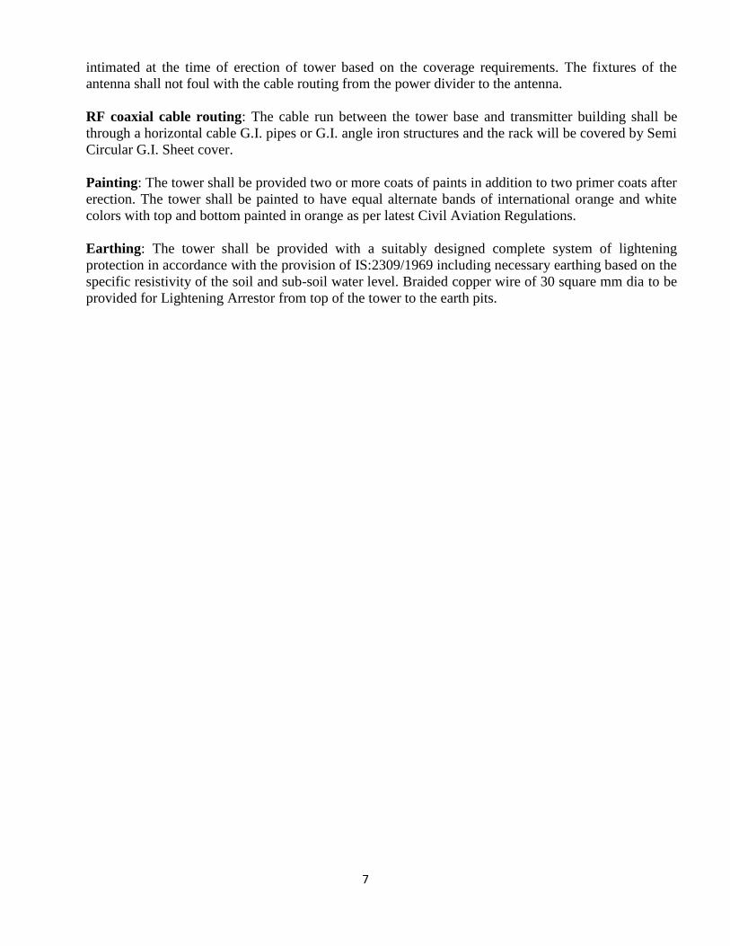
intimated at the time of erection of tower based on the coverage requirements. The fixtures of the
antenna shall not foul with the cable routing from the power divider to the antenna.
RF coaxial cable routing: The cable run between the tower base and transmitter building shall be
through a horizontal cable G.I. pipes or G.I. angle iron structures and the rack will be covered by Semi
Circular G.I. Sheet cover.
Painting: The tower shall be provided two or more coats of paints in addition to two primer coats after
erection. The tower shall be painted to have equal alternate bands of international orange and white
colors with top and bottom painted in orange as per latest Civil Aviation Regulations.
Earthing: The tower shall be provided with a suitably designed complete system of lightening
protection in accordance with the provision of IS:2309/1969 including necessary earthing based on the
specific resistivity of the soil and sub-soil water level. Braided copper wire of 30 square mm dia to be
provided for Lightening Arrestor from top of the tower to the earth pits.
8
B. SELF SUPPORTED TRANSMISSION TOWER
i) Height: Maximum 30 Meter & Minimum 15 meter (From Ground)
ii) Wind load: 47 kg/cm2
iii) Wind Velocity: 170 km/hour
iv) Able to bear a load of 25 kg in addition to cable, cable tray & ladder
v) The design should be approved/vetted by a recognised Engineering College/Institute
Construction details: Steel members and section used in the fabrication are galvanized, conforming
to relevant IS specification i.e. IS: 2629 for tower members IS: 1367 for fasteners and IS:1573 for
washers: Structural steel of the tower members conform to IS: 8500, IS:226, IS:2062 and IS:7215 or
latest IS as applicable. Assembly of all tower members and other structures on tower shall be by
means of hexagonal nuts and bolts along with locking nuts. Minimum thickness of members should be
4 mm. The bolts are treated with standard threads to take the full depth of the nut. The overall force
co-efficient the solidity ratio, actual obstruction area of tower has been considered. The basic wind
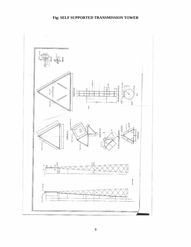
velocity for the site has been taken from the revised BIS Code No. IS:875/1987. The schematic of the
tower is provided on the overleaf.
Lightening protection: The tower will be provided with a suitably designed system of lightening
protection in accordance with the provision of IS:2309/1969. Braided copper wire will be provided for
Lightening Arrestor from top of the tower to the nearest earth pit.
Foundation: Suitable RCC foundation based on the site condition, local terrain, soil conditions, nature
of sub soil, water table and its seasonal variations etc will be laid. Foundation will be protested by
provision of pitching work on sloping terrain to protect the foundation from erosion. The cement,
sand, and concrete used shall be of best grade in the standard ration 1:2:4. The foundation shall be
watered and cured is thoroughly cured.
Antenna hoisting arrangement: Provision for fixing 100 mm dia N.B. Supporting seamless GI pipe
of 8 meter length for side mounting VHF FM Pole type Antenna shall be made on three faces of the
tower. This supporting pole will be fixed in VHF FM Band-II aperture on one of the three faces, to be
intimated at the time of erection of tower based on the coverage requirements. The fixtures of the
antenna shall not foul with the cable routing from the power divider to the antenna.
RF coaxial cable routing: The cable run between the tower base and transmitter building shall be
through a horizontal cable G.I. pipes or G.I. angle iron structures and the rack will be covered by Semi
Circular G.I. Sheet cover.
Painting: The tower shall be provided two or more coats of paints in addition to two primer coats after
erection. The tower shall be painted to have equal alternate bands of international orange and white
colors with top and bottom painted in orange as per latest Civil Aviation Regulations.
Earthing: The tower shall be provided with a suitably designed complete system of lightening
protection in accordance with the provision of IS:2309/1969 including necessary earthing based on the
specific resistivity of the soil and sub-soil water level. Braided copper wire of 30 square mm dia to be
provided for Lightening Arrestor from top of the tower to the earth pits.
9
Fig: SELF SUPPORTED TRANSMISSION TOWER
10
C. Concrete Tower:
DETAILS OF THE MONOPOLE
The 30 m high pre-stressed spun concrete monopole, self-supporting with mountings at different
heights. The entire height of the monopole is to be divided into minimum 3 panels/segments with
the outer diameter at bottom being min 1.0 m and tapering to min 0.4 m at the top. The cross-
section should be annular with thickness varying along height capable of the following:
i) Height: Maximum 30 Meter & Minimum 15 meter (From Ground)
ii) Wind load: 47 kg/cm2
iii) Wind Velocity: 170 km/hour
iv) Able to bear a load of 25 kg in addition to cable, cable tray & ladder
v) The design should be approved/vetted by a recognised Engineering College/Institute
ANALYSIS AND DESIGN
The monopole should be analysed for the various load combinations. The monopole should be
modeled as a beam element. The wind load on the pole should be calculated by using the Gust
factor method as per Clause 8 of IS 875 – Part 3.
The wind loads due to antennae and the panels should be calculated and applied in the analysis.
Dynamic analysis should be done and analysis results to be presented.
As per IS 456 – 2000, the following load combinations should be considered in the analysis:
(i) 1.0 Dead load (DL) + 1.0 Wind Load (WL)
(ii) 1.5 Dead Load + 1.5 Wind Load
(iii)0.9 Dead Load + 1.0 Wind Load
The design of the pre-stressed monopole is to be done as per the limit state method. The limit
state for serviceability and collapse is to be checked for the worst load combination of DL + WL
(for service load combination) and 1.5DL + 1.5WL (for ultimate load combination). LIMIT STATE OF SERVICEABILITY - DEFLECTION
The deformations under service loads at any point on a structure shall not exceed the following:
(i) A rotation of 4 degrees about the vertical axis (twist) or any horizontal axis
(sway) of the structure.
(ii) A horizontal displacement of 3% of the height of the structure.
11
LIMIT STATE OF SERVICEABILITY – CRACKING
Cracking should be within permissible limits given in clause 22.7.1, IS 1343-1980, for type 3
members.
LIMIT STATE OF SERVICEABILITY – MAXIMUM COMPRESSION Maximum permissible compressive stress in flexure due to final pre-stress should be as per
clause 22.8.1.1, IS 1343 – 1980, LIMIT STATE OF COLLAPSE – FLEXURE
The design of the section for the ultimate moment should be based on Clause 22.1.1 of IS 1343 –
1990.
Lightening protection: The tower will be provided with a suitably designed system of lightening
protection in accordance with the provision of IS:2309/1969. Braided copper wire will be provided for
Lightening Arrestor from top of the tower to the nearest earth pit.
Foundation: Suitable RCC foundation based on the site condition, local terrain, soil conditions, nature
of sub soil, water table and its seasonal variations etc will be laid. Foundation will be protested by
provision of pitching work on sloping terrain to protect the foundation from erosion. The cement,
sand, and concrete used shall be of best grade in the standard ration 1:2:4. The foundation shall be
watered and cured is thoroughly cured.
Antenna hoisting arrangement: Provision for fixing 100 mm dia N.B. Supporting seamless GI pipe
of 8 meter length for side mounting VHF FM Pole type Antenna shall be made on three faces of the
tower. This supporting pole will be fixed in VHF FM Band-II aperture on one of the three faces, to be
intimated at the time of erection of tower based on the coverage requirements. The fixtures of the
antenna shall not foul with the cable routing from the power divider to the antenna.
RF coaxial cable routing: The cable run between the tower base and transmitter building shall be
through a horizontal cable G.I. pipes or G.I. angle iron structures and the rack will be covered by Semi
Circular G.I. Sheet cover.
Painting: The tower shall be provided two or more coats of paints in addition to two primer coats after
erection. The tower shall be painted to have equal alternate bands of international orange and white
colors with top and bottom painted in orange as per latest Civil Aviation Regulations.
Earthing: The tower shall be provided with a suitably designed complete system of lightening
protection in accordance with the provision of IS:2309/1969 including necessary earthing based on the
specific resistivity of the soil and sub-soil water level. Braided copper wire of 30 square mm dia to be
provided for Lightening Arrestor from top of the tower to the earth pits.

12
3. VHF TRANSMITTING ANTENNA
An antenna is an electrical device which converts electric power into radio waves. For
community radio antenna must be wideband with copper dipoles and stainless steel/copper
mounting boom. It should have weather and corrosion resistance to suit tropical climate.
Frequency 87 MHz to 108 MHz
Power Rating 200 Watt
Impedance 50 Ohm
Return loss at frequency
of operation
Better than: 23 dB (VSWR 1.15) (factory tuned at
operating frequency) Typical: 26 dB (VSWR 1.1)
Beam width V 80°
Beam width H 220°
Pattern Offset Circular
Polarization Vertical
Termination N – Male
Gain 5 dbd (ERP) should not exceed 100 Watt
Clamps GI
Bays 2
Max Wind Velocity 150 Km/hour
Wind Load (with speed at
150 Km/hour
10 kg
Lightning protection DC grounded
Mounting Position End
13
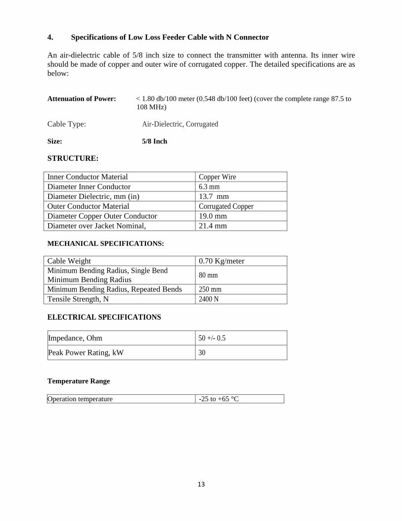
4. Specifications of Low Loss Feeder Cable with N Connector
An air-dielectric cable of 5/8 inch size to connect the transmitter with antenna. Its inner wire
should be made of copper and outer wire of corrugated copper. The detailed specifications are as
below:
Attenuation of Power: < 1.80 db/100 meter (0.548 db/100 feet) (cover the complete range 87.5 to
108 MHz)
Cable Type: Air-Dielectric, Corrugated
Size: 5/8 Inch
STRUCTURE:
Inner Conductor Material Copper Wire
Diameter Inner Conductor 6.3 mm
Diameter Dielectric, mm (in) 13.7 mm
Outer Conductor Material Corrugated Copper
Diameter Copper Outer Conductor 19.0 mm
Diameter over Jacket Nominal, 21.4 mm
MECHANICAL SPECIFICATIONS:
Cable Weight 0.70 Kg/meter
Minimum Bending Radius, Single Bend
Minimum Bending Radius 80 mm
Minimum Bending Radius, Repeated Bends 250 mm
Tensile Strength, N 2400 N
ELECTRICAL SPECIFICATIONS
Impedance, Ohm 50 +/- 0.5
Peak Power Rating, kW 30
Temperature Range
Operation temperature -25 to +65 °C
14
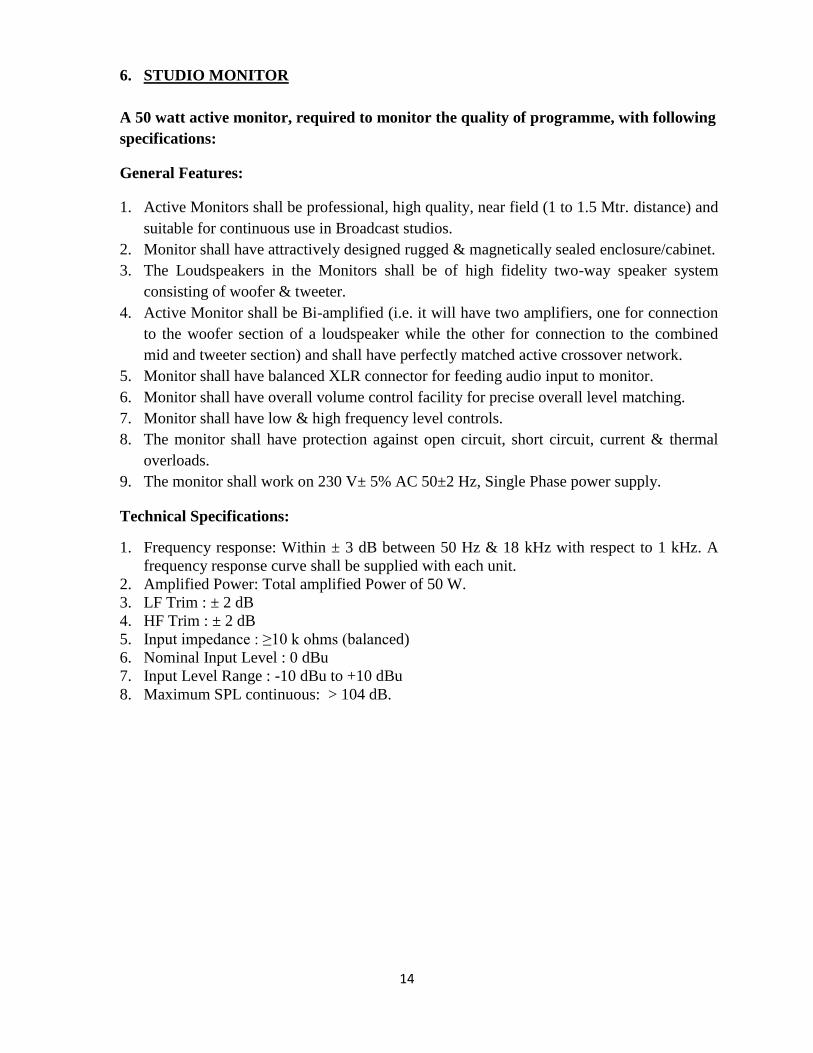
6. STUDIO MONITOR
A 50 watt active monitor, required to monitor the quality of programme, with following
specifications:
General Features:
1. Active Monitors shall be professional, high quality, near field (1 to 1.5 Mtr. distance) and
suitable for continuous use in Broadcast studios.
2. Monitor shall have attractively designed rugged & magnetically sealed enclosure/cabinet.
3. The Loudspeakers in the Monitors shall be of high fidelity two-way speaker system
consisting of woofer & tweeter.
4. Active Monitor shall be Bi-amplified (i.e. it will have two amplifiers, one for connection
to the woofer section of a loudspeaker while the other for connection to the combined
mid and tweeter section) and shall have perfectly matched active crossover network.
5. Monitor shall have balanced XLR connector for feeding audio input to monitor.
6. Monitor shall have overall volume control facility for precise overall level matching.
7. Monitor shall have low & high frequency level controls.
8. The monitor shall have protection against open circuit, short circuit, current & thermal
overloads.
9. The monitor shall work on 230 V± 5% AC 50±2 Hz, Single Phase power supply.
Technical Specifications:
1. Frequency response: Within ± 3 dB between 50 Hz & 18 kHz with respect to 1 kHz. A
frequency response curve shall be supplied with each unit.
2. Amplified Power: Total amplified Power of 50 W.
3. LF Trim : ± 2 dB
4. HF Trim : ± 2 dB
5. Input impedance : ≥10 k ohms (balanced)
6. Nominal Input Level : 0 dBu
7. Input Level Range : -10 dBu to +10 dBu
8. Maximum SPL continuous: > 104 dB.
15
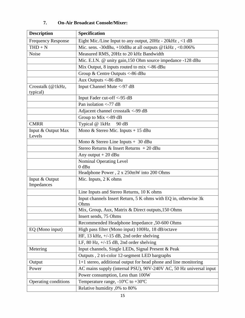
7. On-Air Broadcast Console/Mixer:
Description Specification
Frequency Response Eight Mic./Line Input to any output, 20Hz - 20kHz , <1 dB
THD + N Mic. sens. -30dBu, +10dBu at all outputs @1kHz , <0.006%
Noise Measured RMS, 20Hz to 20 kHz Bandwidth
Mic. E.I.N. @ unity gain,150 Ohm source impedance -128 dBu
Mix Output, 8 inputs routed to mix <-86 dBu
Group & Centre Outputs <-86 dBu
Aux Outputs <-86 dBu
Crosstalk (@1kHz,
typical)
Input Channel Mute <-97 dB
Input Fader cut-off <-95 dB
Pan isolation <-77 dB
Adjacent channel crosstalk <-99 dB
Group to Mix <-89 dB
CMRR Typical @ 1kHz 90 dB
Input & Output Max
Levels
Mono & Stereo Mic. Inputs + 15 dBu
Mono & Stereo Line Inputs + 30 dBu
Stereo Returns & Insert Returns + 20 dBu
Any output + 20 dBu
Nominal Operating Level
0 dBu
Headphone Power , 2 x 250mW into 200 Ohms
Input & Output
Impedances
Mic. Inputs, 2 K ohms
Line Inputs and Stereo Returns, 10 K ohms
Input channels Insert Return, 5 K ohms with EQ in, otherwise 3k
Ohms
Mix, Group, Aux, Matrix & Direct outputs,150 Ohms
Insert sends, 75 Ohms
Recommended Headphone Impedance ,50-600 Ohms
EQ (Mono input) High pass filter (Mono input) 100Hz, 18 dB/octave
HF, 13 kHz, +/-15 dB, 2nd order shelving
LF, 80 Hz, +/-15 dB, 2nd order shelving
Metering Input channels, Single LEDs, Signal Present & Peak
Outputs , 2 tri-color 12-segment LED bargraphs
Output 1+1 stereo, additional output for head phone and line monitoring
Power AC mains supply (internal PSU), 90V-240V AC, 50 Hz universal input
Power consumption, Less than 100W
Operating conditions Temperature range, -10ºC to +30ºC
Relative humidity ,0% to 80%
16
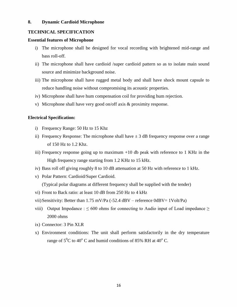
8. Dynamic Cardioid Microphone
TECHNICAL SPECIFICATION
Essential features of Microphone
i) The microphone shall be designed for vocal recording with brightened mid-range and
bass roll-off.
ii) The microphone shall have cardioid /super cardioid pattern so as to isolate main sound
source and minimize background noise.
iii) The microphone shall have rugged metal body and shall have shock mount capsule to
reduce handling noise without compromising its acoustic properties.
iv) Microphone shall have hum compensation coil for providing hum rejection.
v) Microphone shall have very good on/off axis & proximity response.
Electrical Specification:
i) Frequency Range: 50 Hz to 15 Khz
ii) Frequency Response: The microphone shall have ± 3 dB frequency response over a range
of 150 Hz to 1.2 Khz.
iii) Frequency response going up to maximum +10 db peak with reference to 1 KHz in the
High frequency range starting from 1.2 KHz to 15 kHz.
iv) Bass roll off giving roughly 8 to 10 dB attenuation at 50 Hz with reference to 1 kHz.
v) Polar Pattern: Cardioid/Super Cardioid.
(Typical polar diagrams at different frequency shall be supplied with the tender)
vi) Front to Back ratio: at least 10 dB from 250 Hz to 4 kHz
vii) Sensitivity: Better than 1.75 mV/Pa (-52.4 dBV – reference 0dBV= 1Volt/Pa)
viii) Output Impedance : ≤ 600 ohms for connecting to Audio input of Load impedance ≥
2000 ohms
ix) Connector: 3 Pin XLR
x) Environment conditions: The unit shall perform satisfactorily in the dry temperature
range of 50C to 40
o C and humid conditions of 85% RH at 40
o C.
17
9. Portable Solid State Field Recorder:
1. FEATURES AND FACILITIES
i) The recorder shall be lightweight, reliable, rugged, small sized, self contained, one hand
operative with LCD display. The recorder shall be designed to withstand tropical
conditions.
ii) The recorder shall have the facility to record on semiconductor memory.
iii) The recorder shall have the capability of recording stereo audio in 16 bit PCM linear
digital format (.WAV file format).
iv) The buttons/switches for various operations like recording, play, pause, fast forward,
rewind/ review should be provided on the front panel in clearly marked logical layout.
The buttons/switches should be quite sturdy for reliable operation.
v) The record/stop buttons should be so located that it should be possible to easily operate
the recorder for recording/stop while on move. Other necessary switches, buttons and
controls, etc. should be provided at easily accessible locations.
vi) Necessary indicators showing the mode of operation, level, status of the battery and the
memory card capacity, recorded time and remaining time etc. should be distinctly
visible on LCD display panel.
vii) The LCD display panel shall have backlit display.
viii) The recorder shall have the facility to save and delete the recorded material.
ix) The recorder shall have built-in or externally attached Stereo microphone. The capsule of
this stereo microphone should be protruding out of equipment and should be clearly
visible. Stereo microphone connected to equipment using a cable shall not be
accepted. In case of externally attached stereo microphone, the connection should be
such that the microphone doesn‟t get disconnected by sudden jerk.
x) The equipment will also have the provision of connecting external microphone for
recording. This provision will be in addition to provision at Para 9. However, only
one microphone will be operational at a time. Necessary connector/cable for
connecting external microphone will be quoted & supplied.
xi) The recorder should provide facility for transfer of audio data to workstation through
USB connectivity.
xii) The equipment should have level indicators for displaying programme level during
recording/playback.
xiii) The equipment will operate on a battery of adequate capacity to support at least 90
minutes continuously recording. The equipment will have facility to indicate Low
battery level.
2. TECHNICAL SPECIFICATION
2.1 Recording/Play Mode
2.1.1 Recording media 2 GB (or higher) semi-conductor memory
2.1.2 Recording Format PCM Linear Digital (.WAV)
2.1.3 Supported Sampling Rate At least 32/44.1/48 KHz, selectable
18
2.1.4 Supported Bit Resolution ≥ 16 bits
2.2 Power
(a) Internal Battery AA or AAA
OR
(b) Internal Chargeable battery along with charger
OR
(c) (a) and (b) both
2.3 Input
(a) With a built-in /externally attached Stereo microphone
(b) Provision for connecting external microphone
(c) Provision for line input
2.4 Output:
Connectivity through USB 2.0 to Audio Workstation for Data Transfer
2.5 Monitoring:
Provision for headphone monitoring
2.6 Measurements
2.6.1 Frequency Response at Nominal input and output levels w.r.t. 1 KHz and from 50 Hz to 15
kHz : within ± 3dB
2.6.2 THD + Noise at -60 dBu input level and 0 dBu output level (50 Hz.to 15 kHz.) : ≤ 0.3 %
3. WEIGHT
Total weight of recorder including batteries should be less than 500 grams (excluding carrying
case of equipment).
4. DIMENSIONS
The recorder should have compact body and its overall dimensions should be such that it can
easily be held in palm or pocket by the recording personnel.
5. CLIMATIC CONDITIONS
The unit should be designed to work satisfactorily and meet all the specifications in climatic
conditions as existing in India.
19
10. Headphones
TECHNICAL SPECIFICATION
1. Essential features of Headphone
i) The headphone shall be designed to reproduce full audio spectrum (without any
coloration) for quality monitoring in broadcast studios.
ii) It shall be lightweight in construction and shall have provision for stereo/mono
monitoring.
iii) Left & right earpieces shall be matched to reproduce stereo images correctly.
iv) The headphone shall have padded headband so that it is comfortable for extended use.
2. Electrical Specification :
i) Frequency Range : The headphone shall reproduce faithfully audio in the range of 20-
22000 hz.
ii) Electrical impedance : Less than 75 ohms/Channel
iii) Sensitivity at 1Khz : 100 dB SPL at 1mW input
iv) Max Power handling capacity : 100 mW
v) Total harmonic distortion : 0.5% at max. permissible input level.
3. Mechanical requirement :
i) Headphone Diaphragm material : Hard polyvinyl chloride or similar
ii) Ear-pads Material : Leatherette and velvet
iii) Sound coupling to ear/Transducer : Circum-aural/super aural
iv) Average pressure on ears : Max 4/6 N
v) Cord Length (may be detachable) : At least 5 Meter
vi) Phone Plug : Gold plated stereo mini jack (3.5 mm) with gold plated screw-on adaptor
(3.5 mm to 6.35 mm)
vii) Head-strap shall be adjustable.
20
11. Personal Computers
Intel Core i3 Processor, 2.93 GHz, 2 MB Cache, 800 MHz, 2 GB DDR2-RAM, 500 GB SATA
Hard Disk Drive, Double layer DVD Drive, Minimum 18.5” TFT screen, Multimedia Keyboard,
USB 2-button Optical Mouse, 6 USB 2.0 port(2 front, 4 Rear), 10/100 LAN, 2 Nos. Speakers,
PCI slots, Genuine & licensed operating system (to be specified by applicant).
21
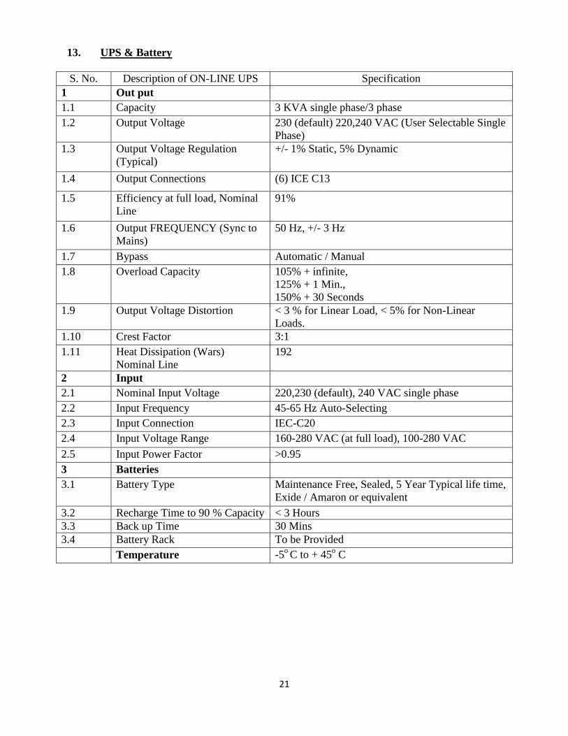
13. UPS & Battery
S. No. Description of ON-LINE UPS Specification
1 Out put
1.1 Capacity 3 KVA single phase/3 phase
1.2 Output Voltage 230 (default) 220,240 VAC (User Selectable Single
Phase)
1.3 Output Voltage Regulation
(Typical)
+/- 1% Static, 5% Dynamic
1.4 Output Connections (6) ICE C13
1.5 Efficiency at full load, Nominal
Line
91%
1.6 Output FREQUENCY (Sync to
Mains)
50 Hz, +/- 3 Hz
1.7 Bypass Automatic / Manual
1.8 Overload Capacity 105% + infinite,
125% + 1 Min.,
150% + 30 Seconds
1.9 Output Voltage Distortion < 3 % for Linear Load, < 5% for Non-Linear
Loads.
1.10 Crest Factor 3:1
1.11 Heat Dissipation (Wars)
Nominal Line
192
2 Input
2.1 Nominal Input Voltage 220,230 (default), 240 VAC single phase
2.2 Input Frequency 45-65 Hz Auto-Selecting
2.3 Input Connection IEC-C20
2.4 Input Voltage Range 160-280 VAC (at full load), 100-280 VAC
2.5 Input Power Factor >0.95
3 Batteries
3.1 Battery Type Maintenance Free, Sealed, 5 Year Typical life time,
Exide / Amaron or equivalent
3.2 Recharge Time to 90 % Capacity < 3 Hours
3.3 Back up Time 30 Mins
3.4 Battery Rack To be Provided
Temperature -5o C to + 45
o C
22
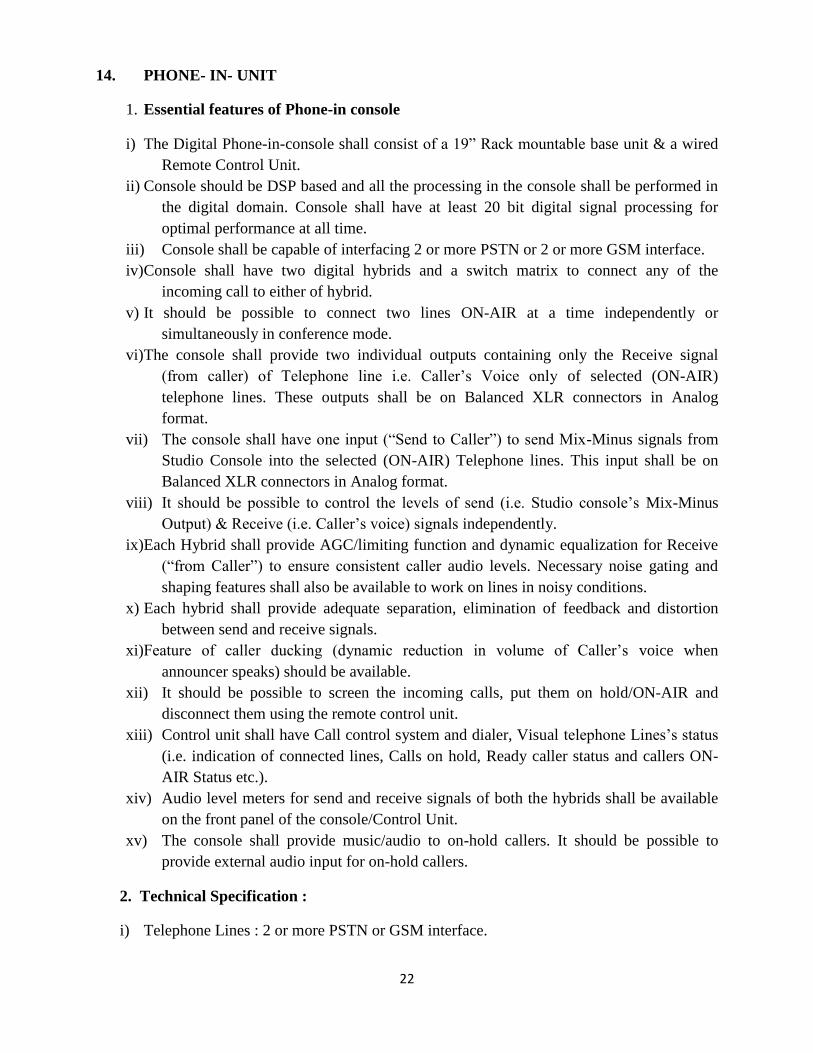
14. PHONE- IN- UNIT
1. Essential features of Phone-in console
i) The Digital Phone-in-console shall consist of a 19” Rack mountable base unit & a wired
Remote Control Unit.
ii) Console should be DSP based and all the processing in the console shall be performed in
the digital domain. Console shall have at least 20 bit digital signal processing for
optimal performance at all time.
iii) Console shall be capable of interfacing 2 or more PSTN or 2 or more GSM interface.
iv) Console shall have two digital hybrids and a switch matrix to connect any of the
incoming call to either of hybrid.
v) It should be possible to connect two lines ON-AIR at a time independently or
simultaneously in conference mode.
vi) The console shall provide two individual outputs containing only the Receive signal
(from caller) of Telephone line i.e. Caller‟s Voice only of selected (ON-AIR)
telephone lines. These outputs shall be on Balanced XLR connectors in Analog
format.
vii) The console shall have one input (“Send to Caller”) to send Mix-Minus signals from
Studio Console into the selected (ON-AIR) Telephone lines. This input shall be on
Balanced XLR connectors in Analog format.
viii) It should be possible to control the levels of send (i.e. Studio console‟s Mix-Minus
Output) & Receive (i.e. Caller‟s voice) signals independently.
ix) Each Hybrid shall provide AGC/limiting function and dynamic equalization for Receive
(“from Caller”) to ensure consistent caller audio levels. Necessary noise gating and
shaping features shall also be available to work on lines in noisy conditions.
x) Each hybrid shall provide adequate separation, elimination of feedback and distortion
between send and receive signals.
xi) Feature of caller ducking (dynamic reduction in volume of Caller‟s voice when
announcer speaks) should be available.
xii) It should be possible to screen the incoming calls, put them on hold/ON-AIR and
disconnect them using the remote control unit.
xiii) Control unit shall have Call control system and dialer, Visual telephone Lines‟s status
(i.e. indication of connected lines, Calls on hold, Ready caller status and callers ON-
AIR Status etc.).
xiv) Audio level meters for send and receive signals of both the hybrids shall be available
on the front panel of the console/Control Unit.
xv) The console shall provide music/audio to on-hold callers. It should be possible to
provide external audio input for on-hold callers.
2. Technical Specification :
i) Telephone Lines : 2 or more PSTN or GSM interface.
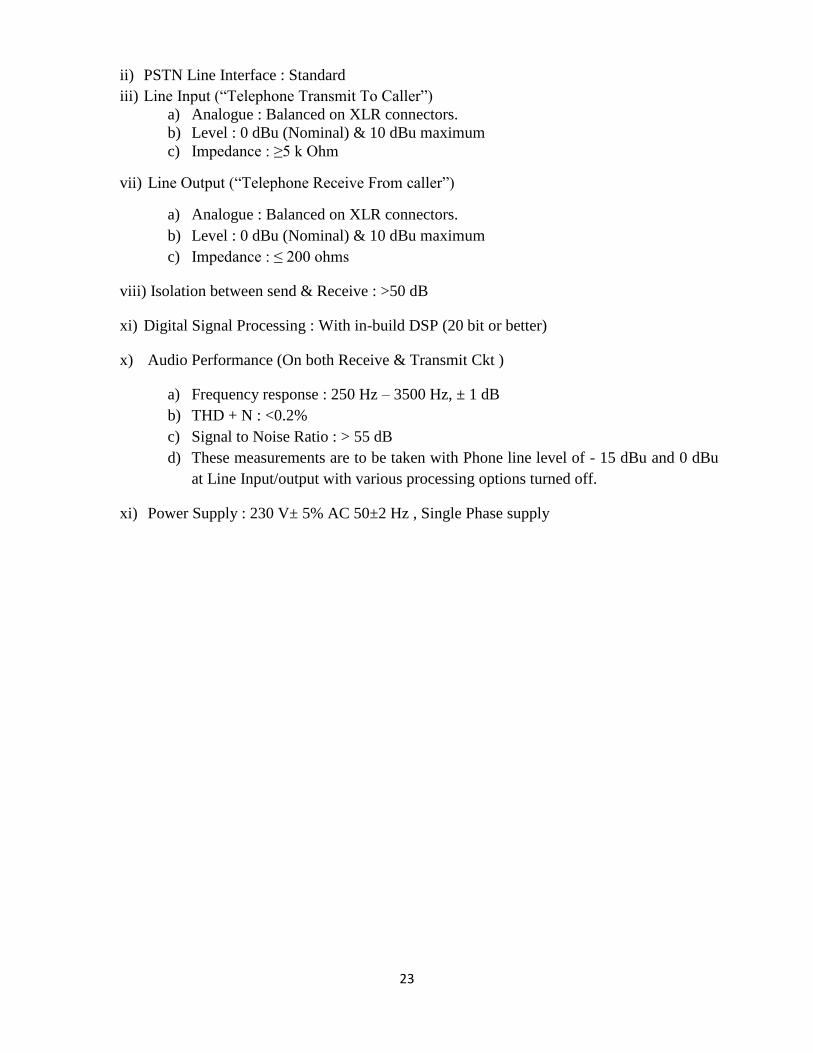
23
ii) PSTN Line Interface : Standard
iii) Line Input (“Telephone Transmit To Caller”)
a) Analogue : Balanced on XLR connectors.
b) Level : 0 dBu (Nominal) & 10 dBu maximum
c) Impedance : ≥5 k Ohm
vii) Line Output (“Telephone Receive From caller”)
a) Analogue : Balanced on XLR connectors.
b) Level : 0 dBu (Nominal) & 10 dBu maximum
c) Impedance : ≤ 200 ohms
viii) Isolation between send & Receive : >50 dB
xi) Digital Signal Processing : With in-build DSP (20 bit or better)
x) Audio Performance (On both Receive & Transmit Ckt )
a) Frequency response : 250 Hz – 3500 Hz, ± 1 dB
b) THD + N : <0.2%
c) Signal to Noise Ratio : > 55 dB
d) These measurements are to be taken with Phone line level of - 15 dBu and 0 dBu
at Line Input/output with various processing options turned off.
xi) Power Supply : 230 V± 5% AC 50±2 Hz , Single Phase supply
24
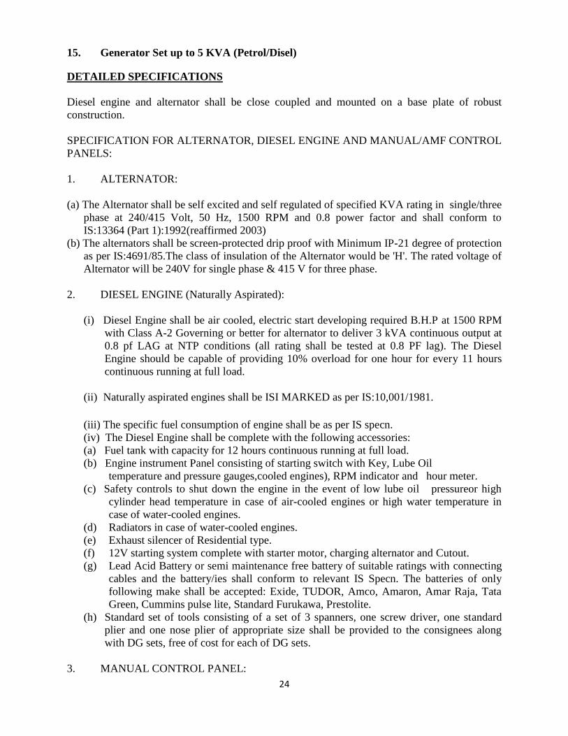
15. Generator Set up to 5 KVA (Petrol/Disel)
DETAILED SPECIFICATIONS
Diesel engine and alternator shall be close coupled and mounted on a base plate of robust
construction.
SPECIFICATION FOR ALTERNATOR, DIESEL ENGINE AND MANUAL/AMF CONTROL
PANELS:
1. ALTERNATOR:
(a) The Alternator shall be self excited and self regulated of specified KVA rating in single/three
phase at 240/415 Volt, 50 Hz, 1500 RPM and 0.8 power factor and shall conform to
IS:13364 (Part 1):1992(reaffirmed 2003)
(b) The alternators shall be screen-protected drip proof with Minimum IP-21 degree of protection
as per IS:4691/85.The class of insulation of the Alternator would be 'H'. The rated voltage of
Alternator will be 240V for single phase & 415 V for three phase.
2. DIESEL ENGINE (Naturally Aspirated):
(i) Diesel Engine shall be air cooled, electric start developing required B.H.P at 1500 RPM
with Class A-2 Governing or better for alternator to deliver 3 kVA continuous output at
0.8 pf LAG at NTP conditions (all rating shall be tested at 0.8 PF lag). The Diesel
Engine should be capable of providing 10% overload for one hour for every 11 hours
continuous running at full load.
(ii) Naturally aspirated engines shall be ISI MARKED as per IS:10,001/1981.
(iii) The specific fuel consumption of engine shall be as per IS specn.
(iv) The Diesel Engine shall be complete with the following accessories:
(a) Fuel tank with capacity for 12 hours continuous running at full load.
(b) Engine instrument Panel consisting of starting switch with Key, Lube Oil
temperature and pressure gauges,cooled engines), RPM indicator and hour meter.
(c) Safety controls to shut down the engine in the event of low lube oil pressureor high
cylinder head temperature in case of air-cooled engines or high water temperature in
case of water-cooled engines.
(d) Radiators in case of water-cooled engines.
(e) Exhaust silencer of Residential type.
(f) 12V starting system complete with starter motor, charging alternator and Cutout.
(g) Lead Acid Battery or semi maintenance free battery of suitable ratings with connecting
cables and the battery/ies shall conform to relevant IS Specn. The batteries of only
following make shall be accepted: Exide, TUDOR, Amco, Amaron, Amar Raja, Tata
Green, Cummins pulse lite, Standard Furukawa, Prestolite.
(h) Standard set of tools consisting of a set of 3 spanners, one screw driver, one standard
plier and one nose plier of appropriate size shall be provided to the consignees along
with DG sets, free of cost for each of DG sets.
3. MANUAL CONTROL PANEL:
25
(i) The Control Panel shall have the following instruments:
(a) Composite meter for digital display of
i) Generator voltage.
ii) Load Current.
iii) Power Factor.
(b) One MCCB of suitable rating for DG sets.
(c) Push button-switch for ON and OFF operation.
(d) Pilot lamps, three in case of single-phase and five numbers in case of three phase (one for
each phase, one for load on set and one for charging on).
(e) Battery charger complete with voltage regulator, voltmeter and ammeter should provide
for Trickle charging as well as Booster charging for charging the battery from mains.
This will be in addition to the battery charging alternator fitted on the engine.
(ii) All the components in the control panel shall be properly mounted, duly wired
and labeled. Suitable terminals are to be provided for panel incoming and outgoing
connections. The instruments/Components shall be of reputed make.
4. Supplier shall furnish complete & satisfactory TTC for engines, alternators complete with
enclosure to be used by them for EACH rating of DG sets clearly indicating make, model and
ratings of the DG sets tested at the time of registration and pre-dispatch inspection. The TTC of
three phase alternators shall cover 'unbalanced load test' as per cl.24 of IS:13364(part-1 or part-
2)/1992 as applicable. However all the engine models /ratings shall need relevant certifications
as per norms. Either of the following types of TTC shall be acceptable:
i) Type Test Certificate issued by recognized Government Lab.
ii) Type Test Certificate issued by recognized Government Lab irrespective of
whether engines and alternators were tested at firm's lab or some other lab, but
witnessed by Government representative.
iii) Type Test Certificate issued by BIS, irrespective of engines and alternators
were tested at firm's lab or some other lab, but witnessed by BIS/ Government
representative.
iv) Type Test Certificate issued by DQA on basis of test conducted at
manufacturer's lab in presence of DQA officers.
5. The testing of diesel generating sets, for all ratings, shall be done at 0.8 PF lag.
6. Testing shall be done at continuous power output for each rating.
7. Necessary gauge/meters shall be fitted to indicate (a) the quantity of fuel left in the
fuel tank, and (b) hours of DG set operation.
8. DG Sets shall conform to norms of Central Pollution Control Board (CPCB).
9. DG sets shall meet the requirements of Environmental(Protection) Rules 1986 as laid
down by Min. of Environment & Forests read with GSR 371 (E) dated 17.5.2002,GSR
520(E) dated 01.7.2003 and No.448 (E)dated 12.07.2004 in respect of noise and
emission norms. DG sets shall also meet all other statutory requirements as notified by
Govt. from time to time.
10. Supplier shall furnish following documents issued by a Govt authorized agency at the
time of registration and pre-despatch inspection:
a) Type approval certificate (TAC) for emission norms for EACH model/family of
engine.
b) TAC from for noise level norms EACH model of DG set.
c) COP for EACH model of DG set and engine used in DG set.
26
11. Scope of supply shall include supply and commissioning of the complete DG set at the
consignee's end but shall exclude installation and erection.
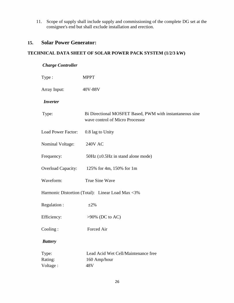
15. Solar Power Generator:
TECHNICAL DATA SHEET OF SOLAR POWER PACK SYSTEM (1/2/3 kW)
Charge Controller
Type : MPPT
Array Input: 40V-88V
Inverter
Type: Bi Directional MOSFET Based, PWM with instantaneous sine
wave control of Micro Processor
Load Power Factor: 0.8 lag to Unity
Nominal Voltage: 240V AC
Frequency: 50Hz (±0.5Hz in stand alone mode)
Overload Capacity: 125% for 4m, 150% for 1m
Waveform: True Sine Wave
Harmonic Distortion (Total): Linear Load Max <3%
Regulation : ±2%
Efficiency: >90% (DC to AC)
Cooling : Forced Air
Battery
Type: Lead Acid Wet Cell/Maintenance free
Rating: 160 Amp/hour
Voltage : 48V
27
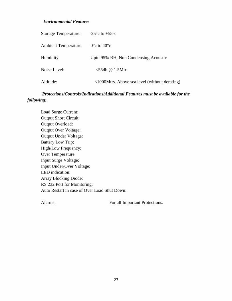
Environmental Features
Storage Temperature: -25°c to +55°c
Ambient Temperature: 0°c to 40°c
Humidity: Upto 95% RH, Non Condensing Acoustic
Noise Level: <55db @ 1.5Mtr.
Altitude: <1000Mtrs. Above sea level (without derating)
Protections/Controls/Indications/Additional Features must be available for the
following:
Load Surge Current:
Output Short Circuit:
Output Overload:
Output Over Voltage:
Output Under Voltage:
Battery Low Trip:
High/Low Frequency:
Over Temperature:
Input Surge Voltage:
Input Under/Over Voltage:
LED indication:
Array Blocking Diode:
RS 232 Port for Monitoring:
Auto Restart in case of Over Load Shut Down:
Alarms: For all Important Protections.
28
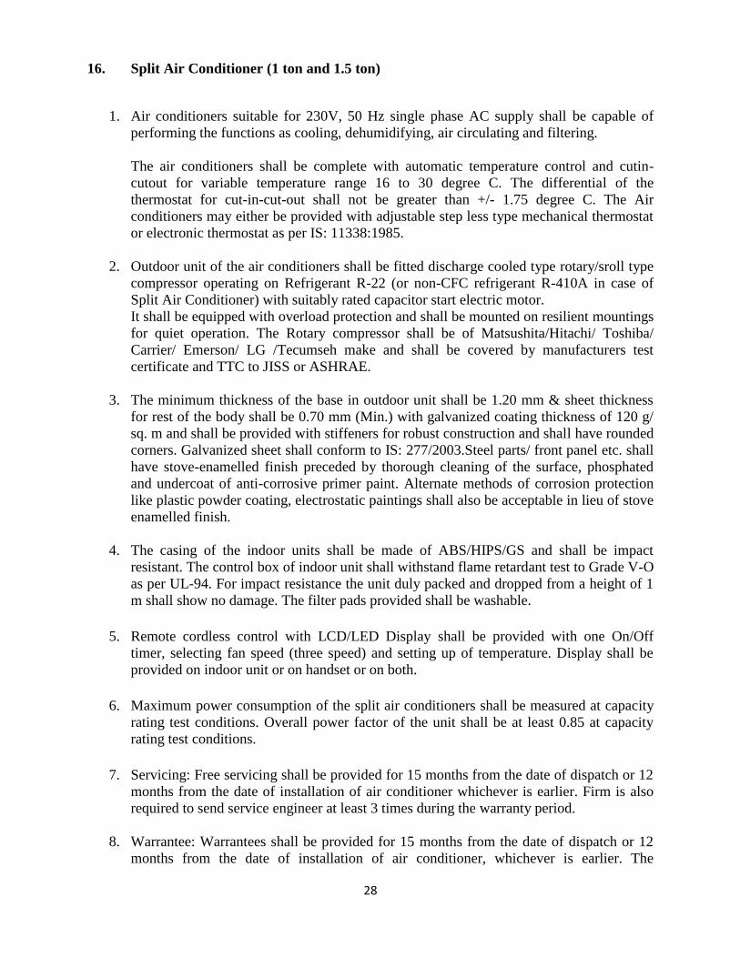
16. Split Air Conditioner (1 ton and 1.5 ton)
1. Air conditioners suitable for 230V, 50 Hz single phase AC supply shall be capable of
performing the functions as cooling, dehumidifying, air circulating and filtering.
The air conditioners shall be complete with automatic temperature control and cutin-
cutout for variable temperature range 16 to 30 degree C. The differential of the
thermostat for cut-in-cut-out shall not be greater than +/- 1.75 degree C. The Air
conditioners may either be provided with adjustable step less type mechanical thermostat
or electronic thermostat as per IS: 11338:1985.
2. Outdoor unit of the air conditioners shall be fitted discharge cooled type rotary/sroll type
compressor operating on Refrigerant R-22 (or non-CFC refrigerant R-410A in case of
Split Air Conditioner) with suitably rated capacitor start electric motor.
It shall be equipped with overload protection and shall be mounted on resilient mountings
for quiet operation. The Rotary compressor shall be of Matsushita/Hitachi/ Toshiba/
Carrier/ Emerson/ LG /Tecumseh make and shall be covered by manufacturers test
certificate and TTC to JISS or ASHRAE.
3. The minimum thickness of the base in outdoor unit shall be 1.20 mm & sheet thickness
for rest of the body shall be 0.70 mm (Min.) with galvanized coating thickness of 120 g/
sq. m and shall be provided with stiffeners for robust construction and shall have rounded
corners. Galvanized sheet shall conform to IS: 277/2003.Steel parts/ front panel etc. shall
have stove-enamelled finish preceded by thorough cleaning of the surface, phosphated
and undercoat of anti-corrosive primer paint. Alternate methods of corrosion protection
like plastic powder coating, electrostatic paintings shall also be acceptable in lieu of stove
enamelled finish.
4. The casing of the indoor units shall be made of ABS/HIPS/GS and shall be impact
resistant. The control box of indoor unit shall withstand flame retardant test to Grade V-O
as per UL-94. For impact resistance the unit duly packed and dropped from a height of 1
m shall show no damage. The filter pads provided shall be washable.
5. Remote cordless control with LCD/LED Display shall be provided with one On/Off
timer, selecting fan speed (three speed) and setting up of temperature. Display shall be
provided on indoor unit or on handset or on both.
6. Maximum power consumption of the split air conditioners shall be measured at capacity
rating test conditions. Overall power factor of the unit shall be at least 0.85 at capacity
rating test conditions.
7. Servicing: Free servicing shall be provided for 15 months from the date of dispatch or 12
months from the date of installation of air conditioner whichever is earlier. Firm is also
required to send service engineer at least 3 times during the warranty period.
8. Warrantee: Warrantees shall be provided for 15 months from the date of dispatch or 12
months from the date of installation of air conditioner, whichever is earlier. The
29
compressor shall have additional warrantee under AMC of 4 years (In addition to above
warrantee of 12/15 months on whole unit.)
9. Installation: The installation charges at consignee's site shall include the following work:-
i) Mounting/Fitting indoor and outdoor units at the respective locations.
ii) Laying refrigerant piping of 6mtrs length and connecting both the units after
drilling hole/holes in the wall, if required. The thickness of the copper tubing
shall not be less than 0.70mm.
iii) Insulating the suction pipe with expanded polyethylene foam with 5mm thick
tubing.
iv) Laying 15mm drain pipe 6m length to drain out the condensate water being
formed in the indoor unit.
v) Leak testing of the entire system.
vi) Charging Refrigerant gas in the unit.
vii) Suitable electric wiring between indoors and outdoors units up to 6 mtrs length up to
switch within 3 m of location of indoor unit. Switches/ Sockets /Plugs are not included in
the scope of supply.
Installation/ Warranty Charges for Split Air-Conditioner
Split Air-Conditioner With Rotary Compressor (R22 Refrigerant)
Specification:-
The scope of installation shall include installation at consignee's site.
Specification :-
Split type air conditioners with BEE Star rating label & rating capacity conforming to IS:
1391(Part-2)-1992 with amdts No.1 to 4 fitted with rotary compressor suitable for using
HCFC refrigerant (R-22) for wall mounting .

30
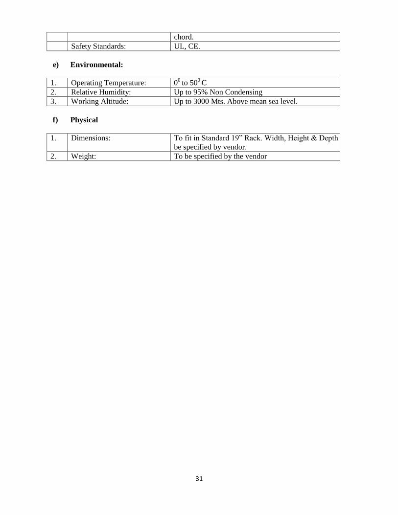
17. Broadcast Audio Processor:
Specifications:
1. The Broadcast Audio Processor shall be designed for continuous, unattended and trouble free
operation in the broadcast chain of a VHF FM Transmitter at a community Radio Station.
2. The processor shall have Digital Signal Processing technique. It shall be able to provide
minimum 5 band audio processing with compression, limiting, clipping automatic wideband
gain control etc.
3. The processor shall have phase limiter to maximize audible transparency and should have
provision for stereo enhancement and high/low frequency enhancement.
4. The processor shall help to reduce noise and enhance loudness & clarity.
5. Radio Frequency Interference (RFI)/ Electromagnetic Compatibility (EMC) filters and power
supply surge protection shall be provided at the mains input.
6. The processor shall meet the following technical parameters:
a) Analog Audio Input:
1. Configuration: Left and Right/ Stereo
2. Nominal Input Level: Software adjustable from-4.0 to +12.0dBu
3. Maximum Input Level: +24 dBu (impedance>10kΩ)
4. A/D Conversion Minimum 24 Bit
5. Connectors: Balanced XLR Female, EMI Suppressed.
b) Analog Audio Output:
1. Configuration: Left and Right/ Stereo. Flat or pre-emphasized (at
50µs or 75 µs) software selectable.
2. Output Level(100% peak
modulation)
Adjustable from -6.0 to +20 dBu software
adjustable.
3. Signal to Noise:
(20Hz to 15 kHz )
≥ 80 Db unweighted
4. Distortion (20Hz to 15 kHz) ≤ 0.02% THD.
5. Cross Talk:
(20 z to 15 kHz)
≤ -70 Db
6. D/A Conversion: Minimum 24 Bit
7. Connectors Balanced XLR Male, EMI Suppressed.
c) Remote Computer Interface:
1. Configuration TCP/IP Protocol via modern of Ethernet interface
2. Connectors: RS-232 Port or RJ-45, EMI Suppressed
d) Power:
1. Voltage 230 Volts AC ± 5%, 50Hz ±2%
Connector: IEC, EMI Suppressed, detachable 3-wire power
31
chord.
Safety Standards: UL, CE.
e) Environmental:
1. Operating Temperature: 00
to 500
C
2. Relative Humidity: Up to 95% Non Condensing
3. Working Altitude: Up to 3000 Mts. Above mean sea level.
f) Physical
1. Dimensions: To fit in Standard 19” Rack. Width, Height & Depth to
be specified by vendor.
2. Weight: To be specified by the vendor