
Fuji NDIR Analyzerzkj.pdf
20
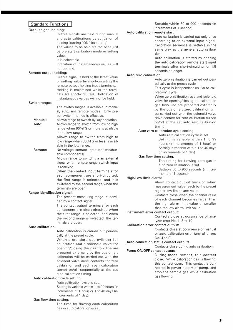
SPECIFICATIONS FEATURES DATA SHEET ZKJ NDIR TYPE INFRARED GAS ANALYZER (5-COMP ONENT ANAL YZER) This gas analyzer (ZKJ) is capable of measuring the con- centrations of NO, SO2, CO2, CO, CH4 and O2 components in sample gas. NO, SO2, CO2, CO and CH4 are measured by non-disper- sion infrared method (NDIR), while O2 is measured by built-in type paramagnetic method sensor or external- mount type zirconia method sensor. A maximum of 5 components including O2 (max. 4 components except for O2 measurement) are simultaneously measurable. The mass flow type twin detector of high sensitivity and reliability adopted in the infrared ray method detection block makes the measurement hardly affected by interfer- ing components. In addition, a microprocessor is built in and a large-size liquid crystal display is equipped for easier operation, higher accuracy and more functions. Optimum as an analyzer unit of measurement system for combustion exhaust gas from refuse incinerator and boiler, or gas from diff erent industrial furnaces. Standard Specifications Principle of measurement: NO, SO2, CO2, CO, CH4; Non-dispersion infrared-ray absorption method Single light source and double beams (double-beam system) O2 ; Paramagnetic O2 sensor (built in) or zir- conia O2 sensor (externally installed) Measurable gas components and measuring range: 1 . Measure fiv e components including O 2 simultaneously and continuously Simultaneously and continuously measures up to four components out of NO, SO2, CO, CO2 and CH4, plus O2, or up to totally five components. 2. Hardly aff ected by interfer ence by other gases The mass flow type twin detector of high sensitivity and reliability adopted makes the measurement hardly affected by interfering components, ensuring a stable operation. 3. Equipped with abundant func tions O2 conversion, average value computation, automatic calibration, one touch calibration, upper/lower limit alarm, remote measurement range changeover, range identification signal output, etc. incorporated can configure applications to match particular uses. 4. Easy-to-see large LCD unit The large LCD unit adopted allows observing easily the indication of all measured components and computation values. The interactive operation facilitates setting. 5. 19 inch rac k mount structure The mainframe unitized to 19 inch rack type and electrical signal input/output terminal unit also unitized easily configure a gas analyzer system. 6. Maximum range ratio is 1 to 25 Measuring ranges are changeable. 7. Drift +/-1% FS/week (more than 0 to 200ppm range) • Max. 5 components measurement including O2. • Measuring range ratio ≤ 1:5 (O2) ≤ 1:25 (except for O2) • Measuring ranges are changeable between the specified minimum and maximum range Settable one range or two ranges *For measurable components and possible combinations of measuring ranges, refer to T ables 1-(1) to (3). Minimum range Maximam range CO2 CO CH4 O2 (built in) O2 (External Zirconia) 0 – 50ppm 0 – 100vol% 0 – 100vol% 0 – 100vol% 0 – 25vol% 0 – 200ppm 0 – 5vol% 0 – 20ppm 0 – 25vol% 0 – 5vol% NO SO2 0 – 50ppm 0 – 5000ppm 0 – 10vol% 0 – 50ppm EDS3-123h Jan. 9, 2008 Date
Transcript of Fuji NDIR Analyzerzkj.pdf
7/28/2019 Fuji NDIR Analyzerzkj.pdf
http://slidepdf.com/reader/full/fuji-ndir-analyzerzkjpdf 1/20
SPECIFICATIONSFEATURES
DATA SHEET ZKJ
NDIR TYPE INFRARED GAS ANALYZER(5-COMPONENT ANALYZER)
This gas analyzer (ZKJ) is capable of measuring the con-
centrations of NO, SO2, CO2, CO, CH4 and O2 components
in sample gas.
NO, SO2, CO2, CO and CH4 are measured by non-disper-
sion infrared method (NDIR), while O 2 is measured by
built-in type paramagnetic method sensor or external-
mount type zirconia method sensor. A maximum of 5
components including O2 (max. 4 components except for
O2 measurement) are simultaneously measurable.
The mass flow type twin detector of high sensitivity and
reliability adopted in the infrared ray method detection
block makes the measurement hardly affected by interfer-
ing components.In addition, a microprocessor is built in and a large-size
liquid crystal display is equipped for easier operation,
higher accuracy and more functions.
Optimum as an analyzer unit of measurement system
for combustion exhaust gas from refuse incinerator and
boiler, or gas from different industrial furnaces.
Standard Specifications
Principle of measurement:
NO, SO2, CO2, CO, CH4;Non-dispersion infrared-ray absorption
method
Single light source and double beams
(double-beam system)
O2 ; Paramagnetic O2 sensor (built in) or zir-
conia O2 sensor (externally installed)
Measurable gas components and measuring range:
1. Measure five components including O2 simultaneously
and continuously
Simultaneously and continuously measures up to four
components out of NO, SO2, CO, CO2 and CH4, plus
O2, or up to totally five components.
2. Hardly affected by interference by other gases
The mass flow type twin detector of high sensitivity
and reliability adopted makes the measurement hardly
affected by interfering components, ensuring a stable
operation.
3. Equipped with abundant functions
O2 conversion, average value computation, automatic
calibration, one touch calibration, upper/lower limit
alarm, remote measurement range changeover, range
identification signal output, etc. incorporated can
configure applications to match particular uses.
4. Easy-to-see large LCD unitThe large LCD unit adopted allows observing easily
the indicat ion of a l l measured components and
computation values.
The interactive operation facilitates setting.
5. 19 inch rack mount structure
The mainframe unitized to 19 inch rack type and
electrical signal input/output terminal unit also unitized
easily configure a gas analyzer system.
6. Maximum range ratio is 1 to 25
Measuring ranges are changeable.
7. Drift +/-1% FS/week (more than 0 to 200ppm range)
• Max. 5 components measurement including O2.
• Measuring range ratio ≤ 1:5 (O2)
≤ 1:25
(except for O2)
• Measuring ranges are changeable between
the specified minimum and maximum range
Settable one range or two ranges
*For measurable components and possible combinations
of measuring ranges, refer to Tables 1-(1) to (3).
Minimum range Maximam range
CO2
CO
CH4
O2 (built in)
O2 (External Zirconia)
0 – 50ppm
0 – 100vol%
0 – 100vol%
0 – 100vol%
0 – 25vol%
0 – 200ppm
0 – 5vol%
0 – 20ppm
0 – 25vol%0 – 5vol%
NO
SO2 0 – 50ppm
0 – 5000ppm
0 – 10vol%
0 – 50ppm
EDS3-123hJan. 9, 2008Date
7/28/2019 Fuji NDIR Analyzerzkj.pdf
http://slidepdf.com/reader/full/fuji-ndir-analyzerzkjpdf 2/20
ZKJ
2
Measured value indication:
Digital indication in 4 digits
(LCD with back light)
• Instantaneous value of each component
• Instantaneous value after O2 correction
(only in NO, SO2, CO measurement
with O2)
• Average value after O2 correction
(only in NO, SO2, CO measurementwith O2)
• O2 average value
Analog output signals:
* Inputs/outputs of analog signals are
possible by combining with the input/
output terminal module.
4 to 20mA DC or 0 to 1V DC,
non-isolated output ; 12 points max.
max.load 550Ω. for 4 to 20 mA DC
min.load 100Ω. for 0 to 1V DC
* Refer to Table 2, for the channel No.
of displayed values and analog output
signals.
Analog input signal:For signal input from externally installed
O2 sensor.
Signal requirement;
(1) Signal from Fuji’s Zirconia O2 sen-
sor (TYPE: ZFK7)
(2) 0 to 1V DC from an O2 sensor
Input section is not isolated. This fea-
ture is effective when an O2 sensor is
not built in.
(Depend on O2 input signal, measured
concentration indication and O2 conver-
sion.)
Relay contact output:
1a contact (250V AC/2A, resistive load)
Instrument error, calibration error,
range identification, auto calibration
status, pump ON/OFF, peak alarm.
1c contact (250V AC/2A, resistive load
selectable 6 outputs)
High/Low limit alarm contact output.
Power disconnection alarm.
* All relay contacts are isolated mutu-
ally and from the internal circuit.
Contact input: No-voltage contact (ON/0V, OFF/5V
DC, 5mA flowing at ON)
Remote range switch, auto calibra-
tion remote start, remote holding,average value resetting, pump ON/
OFF
Isolated from the internal circuit with
photocoupler. Contact inputs are not
isolated from one another.
Transmission output:
Solenoid valve drive signal for automat-
ic calibration.
Transistor output (100mA or less)
Power supply: Voltage rating ; 100V to 240V AC
Allowable range ; 85V to 264V AC
Frequency ; 50Hz/60Hz
Power consumption; 250VA max.
Inlet ; Conform to EN60320Protection Class 1
Operating conditions:
Ambient temperature ; -5°C to 45°C
Ambient humidity ; 90% RH max.,
non-condensing
Storage conditions:
Ambient temperature; -20°C to 60°C
Ambient humidity ; 100% RH max.,
non-condensing
Dimensions (H x W x D):
Analyzer main unit;
177 x 483 x 600mm
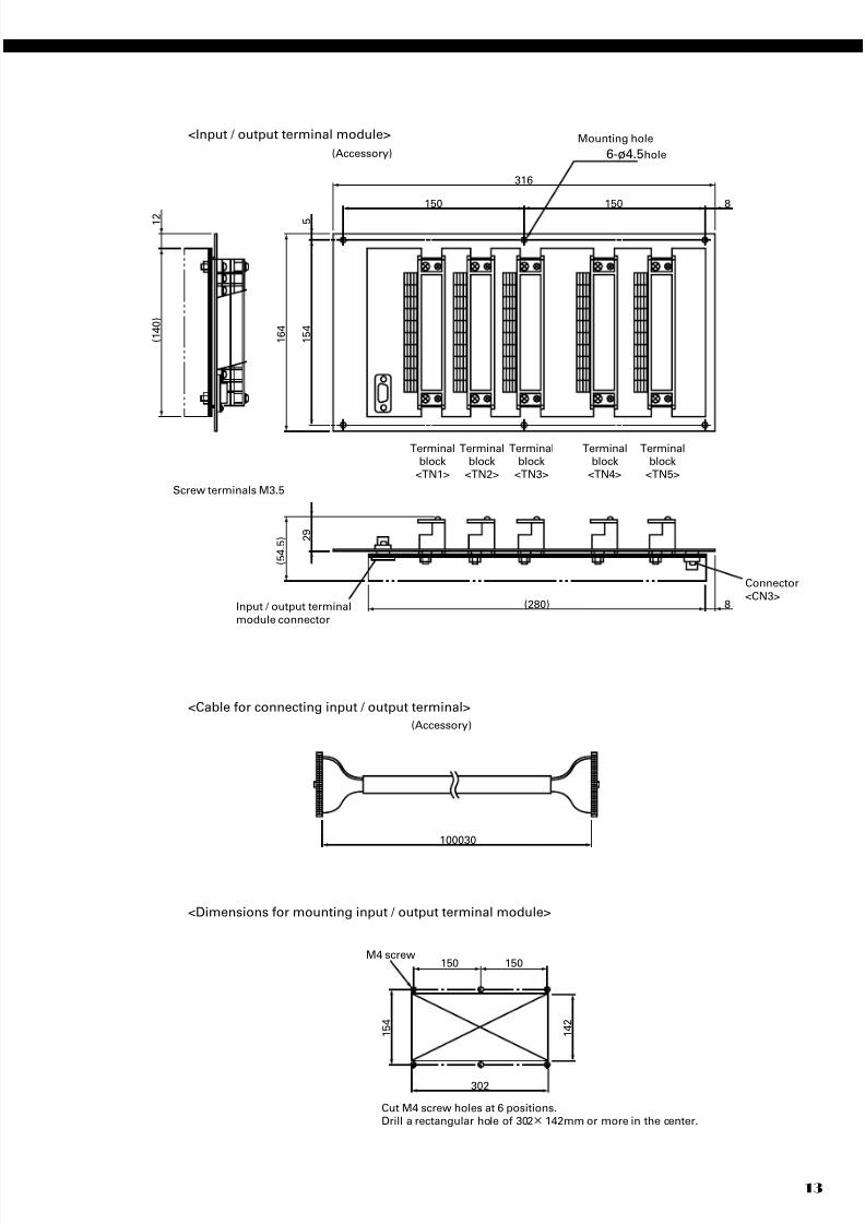
Input/output terminal module;
164 x 318 x 55mmMass: Approx. 22 kg (only Analyzer)
Finish color: Front panel; Off-white (Munsell 10Y7.5/0.5
or equivalent)
Casing; Plating, Steel-blue (gray)
Enclosure: Steel casing, for indoor use
Material of gas-contacting parts:
Gas inlet/outlet; SUS304
Sample cell; SUS304,chloroprene rubber
Infrared-ray transmitting window; CaF2
O2 sensor sample cell : SUS316
Internal piping; Toaron, Teflon
Gas inlet/outlet: Rc1 /4 or NPT1 /4 internal thread
Purge gas flow rate:1L/min ( when required)
7/28/2019 Fuji NDIR Analyzerzkj.pdf
http://slidepdf.com/reader/full/fuji-ndir-analyzerzkjpdf 3/20 3
Standard Functions
Output signal holding:
Output signals are held during manual
and auto calibrations by activation of
holding ( turning “ON” its setting).
The values to be held are the ones just
before start calibration mode or setting
value.
It is selectable.
Indication of instantaneous values will
not be held.
Remote output holding:
Output signal is held at the latest value
or setting value by short-circuiting the
remote output holding input terminals.
Holding is maintained while the termi-
nals are short-circuited. Indication of
instantaneous values will not be held.
Switch ranges :
The switch ranges is available in manu-
al, auto, and remote modes. Only pre-
set switch method is effective.Manual: Allows range to switch by key operation.
Auto: Allows range to switch from low to high
range when 90%FS or more is available
in the low range.
Allows range to switch from high to
low range when 80%FS or less is avail-
able in the low range.
Remote: No-voltage contact input (for measur-
able components)
Allows range to switch via an external
signal when remote range switch input
is received.
When the contact input terminals for
each component are short-circuited,
the first range is selected, and it is
switched to the second range when the
terminals are open.
Range identification signal:
The present measuring range is identi-
fied by a contact signal.
The contact output terminals for each
component are short-circuited when
the first range is selected, and when
the second range is selected, the ter-
minals are open.
Auto calibration:
Auto calibration is carried out periodi-cally at the preset cycle.
When a standard gas cy l inder for
calibration and a solenoid valve for
opening/closing the gas flow line are
prepared externally by the customer,
calibration will be carried out with the
solenoid valve drive contacts for zero
calibration and each span calibration
turned on/off sequentially at the set
auto calibration timing.
Auto calibration cycle setting:
Auto calibration cycle is set.
Setting is variable within 1 to 99 hours (in
increments of 1 hour) or 1 to 40 days (in
increments of 1 day).
Gas flow time setting:
The time for flowing each calibration
gas in auto calibration is set.
Settable within 60 to 900 seconds (in
increments of 1 second)
Auto calibration remote start:
Auto calibration is carried out only once
according to an external input signal.
Calibration sequence is settable in the
same way as the general auto calibra-
tion.
Auto calibration is started by openingthe auto calibration remote start input
terminals after short-circuiting for 1.5
seconds or longer.
Auto zero calibration:
Auto zero calibration is carried out peri-
odically at the preset cycle.
This cycle is independent on “Auto cali-
bradion” cycle.
When zero calibration gas and solenoid
valve for opening/closing the calibration
gas flow line are prepared externally
by the customer, zero calibration will
be carried out with the solenoid valve
drive contact for zero calibration turned
on/off at the set auto zero calibration
timing.
Auto zero calibration cycle setting:
Auto zero calibration cycle is set.
Setting is variable within 1 to 99
hours (in increments of 1 hour) or
Setting is variable within 1 to 40 days
(in increments of 1 day)
Gas flow time setting:
The timing for flowing zero gas in
auto zero calibration is set.
Settable 60 to 900 seconds (in incre-
ments of 1 second)High/Low limit alarm:
Alarm contact output turns on when
measurement value reach to the preset
high or low limit alarm value.
Contacts close when the channel value
of each channel becomes larger than
the high alarm limit value or smaller
than the low alarm limit value.
Instrument error contact output:
Contacts close at occurrence of ana-
lyzer error No. 1, 3 or 10.
Calibration error contact output:
Contacts close at occurrence of manual
or auto calibration error (any of errors
No. 4 to 9).
Auto calibration status contact outputs:
Contacts close during auto calibration.
Pump ON/OFF contact output:
During measurement, this contact
close. While calibration gas is flowing,
this contact open. This contact is con-
nected in power supply of pump, and
stop the sample gas while calibration
gas flowing.
7/28/2019 Fuji NDIR Analyzerzkj.pdf
http://slidepdf.com/reader/full/fuji-ndir-analyzerzkjpdf 4/20
ZKJ
4
Standard Requirements for Sample Gas
Flow rate : 0.5L / min ±0.2L / min
Temperature : 0 to 50°C
Pressure : 10 kPa or less (Gas outlet side should
be open to the atmospheric air.)
Dust : 100µg/Nm3 or less in particle size of
1µm or less
Mist : Unallowable
Moisture : Below a level where saturation occurs
at 2°C (condensation unallowable).
Corrosive component:
1 ppm or less
Standard gas for calibration:
Zero gas ; Dry N2
Span gas ; Each sample gas having
concentration 90 to 100%
of its measuring range (rec-
ommended).
Gas beyond concentration
100%FS is unusable.
In case a zirconia O2 analyzer is installed
externally and calibration is carried out
on the same calibration gas line:
Zero gas ; Dry air or atmospheric air
(provided without CO2 sen-
sor)
Span gas ; For other than O2 measure-ment , each sample gas
having concentrat ion 90
to 100% of its measuring
range.
For O2 measurement, O2
gas of 1 to 2 vol%.
Performance
Repeatability : ±0.5% of full scale
Linearity : ±1% of full scale
Zero drift : ±1% of full scale/week
(±2% of full scale/week; range be
tween 0 to 50ppm and 0 to 200ppm)
(±2% of full scale/day; smaller than
0 to 50ppm range)
Span drift : ±2% of full scale/week
(±2% of full scale/day; smaller than
0 to 50ppm range)
Response time :
(for 90% FS response)
15 sec electrical response
Within 60 seconds including replace-
ment time of sampling gas (when gas
flow rate is 0.5L/min)
Gas replacement time depends on the
number of measuring components,and
measuring range
Optional Functions
O2 correction: Conversion of measured NO, SO2 and
CO gas concentrations into values at
standard O2 concentration
Correction formula: C = × Cs
C : Sample gas concentration after O2
correctionCs : Measured concentration of sample
gas
Os : Measured O2 concentration
(Limit settable, 1 to 20%O2)
On: Standard O2 concentration (value
changeable by setting; 0 to 19%O2)
Average value after O2 correction and O2 average value
calculation: The result of O2 correction or instanta-
neous O2 value can be outputted as an
average value in the preset period of
time.
Used for averaging is the moving aver-
age method in which sampling is car-
ried out at intervals of 30 seconds.
(Output is updated every 30 seconds.
It is the average value in the deter-
mined period of time just before the
latest updating.)
Averaging time is settable within 1 to
59 minutes (in increments of 1 min-
ute) or 1 to 4 hours (in increments of 1
hour).
Average value resetting:
The above-mentioned output of average
value is started from the initial state by
opening the average value resetting in-
put terminals after short-circuiting for 1.5seconds or longer.
Output is reset by short-circuiting and
restarted by opening.
CO concentration peak count alarm:
(added only for CO/O2 measurement)
Alarm output turns on according to the
preset concentration and count.
Whenever the instantaneous value of
CO exceeds the preset concentration
value, count increments. If the count
exceeds the preset value in one hour,
the alarm contacts close.
Communication function:
RS-232C (9pins D-sub)
Half-duplex bit serial
Start-stop synchronization
ModbusTM protcol
Contents: Read/Wright parameters
Read measurement concen-
tration and instrument status
Remark: When connecting via RS-485 in-
terface, a RS-232C RS-485
converter should be used.
21–On
21–Os
7/28/2019 Fuji NDIR Analyzerzkj.pdf
http://slidepdf.com/reader/full/fuji-ndir-analyzerzkjpdf 5/205
Installation Requirements
• Indoor use. (Select a place where the equipment does
not receive direct sunshine, draft/rain or radiation from
hot substances. If such a place cannot be found, a roof
or cover should be prepared for protection.)
• Avoide a place where receives heavy vibration
• Select a place where atmospheric air is clean
EC Directive Compliance
The product conforms to the requirements of the Low
Voltage Directive 73/23/EEC and EMC directive 89/336/
EEC (as amended by Directive 92/31/EEC), both as
amended by Directive 93/68/EEC.
It conforms to following standards for product safety and
electromagnetic compatibility ;
EN61010-1 : 2001 Safet y req uire ment s for e lect rica l
equipment for measurement, control
and laboratory use.
“Installation Category II”“Pollution Degree 2”
EN61326-1 : 1997, AI: 1998, A2: 2001
Electrical equipment for measurement,
control and laboratory use — EMC re-
quirements.
*The product mounted in a steel enclosure conforms
to the requirements of EMC directive.
7/28/2019 Fuji NDIR Analyzerzkj.pdf
http://slidepdf.com/reader/full/fuji-ndir-analyzerzkjpdf 6/20
ZKJ
6
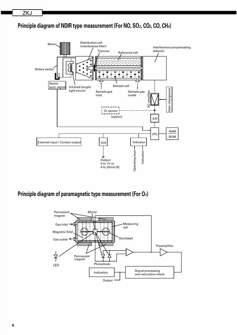
Principle diagram of paramagnetic type measurement (For O2)
Output
IndicationSignal processingand calculation block
Preamplifier
Gas outlet
Gas inlet Measuringcell
Mirror
Magnetic field
Photodiode
Permanentmagnet
Permanentmagnet
LED
Dumbbell
Principle diagram of NDIR type measurement (For NO, SO2, CO2, CO, CH4)
Sample gasoutlet
A C a m p l i f i e r
O p e r a t i n g k e y s
I n d i c a t i o n
G a i n c h a n g e o v e r
Sample cell
Sample gasinlet
TrimmerReference cell
Interference compensating
detector
Distribution cell
(interference filter)
Infrared (single)light source
Motor
Rotary sector
Sectorsync. signal
O2 sensor
(option) A/D
CPU
IndicatorD/AExternal input / Contact output
RAM
ROM
Output0 to 1V or
4 to 20mA DC
7/28/2019 Fuji NDIR Analyzerzkj.pdf
http://slidepdf.com/reader/full/fuji-ndir-analyzerzkjpdf 7/20 7
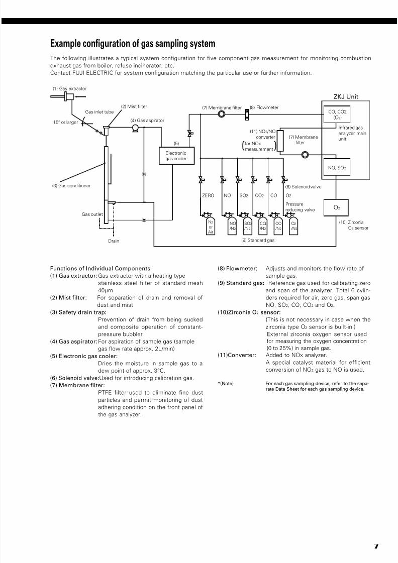
Example configuration of gas sampling system
for NOx
measurement
O2
NO, SO2
(1) Gas extractor
Gas inlet tube
15° or larger (4) Gas aspirator
(2) Mist filter
(5)
(3) Gas conditioner
Gas outlet
Drain
Electronic
gas cooler
(8) Flowmeter(7) Membrane filter
(7) Membrane
filter
CO, CO2
(O2)
NO
/N2
N2
or
Air
(9) Standard gas
ZERO NO
SO2
/N2
SO2
CO2
/N2
CO2
CO
/N2
CO
O2
/N2
O2
(6) Solenoid valve
Pressure
reducing valve
Infrared gas
analyzer main
unit
ZKJ Unit
(11) NO2 /NO
converter
(10) Zirconia
O2 sensor
Functions of Individual Components
(1) Gas extractor:Gas extractor with a heating type
stainless steel filter of standard mesh
40µm
(2) Mist filter: For separation of drain and removal ofdust and mist
(3) Safety drain trap:
Prevention of drain from being sucked
and composite operation of constant-
pressure bubbler
(4) Gas aspirator:For aspiration of sample gas (sample
gas flow rate approx. 2L/min)
(5) Electronic gas cooler:
Dries the moisture in sample gas to a
dew point of approx. 3°C.
(6) Solenoid valve:Used for introducing calibration gas.
(7) Membrane filter:
PTFE filter used to eliminate fine dustparticles and permit monitoring of dust
adhering condition on the front panel of
the gas analyzer.
(8) Flowmeter: Adjusts and monitors the flow rate of
sample gas.
(9) Standard gas: Reference gas used for calibrating zero
and span of the analyzer. Total 6 cylin-
ders required for air, zero gas, span gasNO, SO2, CO, CO2 and O2.
(10)Zirconia O2 sensor:
(This is not necessary in case when the
zirconia type O2 sensor is built-in.)
External zirconia oxygen sensor used
for measuring the oxygen concentration
(0 to 25%) in sample gas.
(11)Converter: Added to NOx analyzer.
A special catalyst material for efficient
conversion of NO2 gas to NO is used.
*(Note) For each gas sampling device, refer to the sepa-
rate Data Sheet for each gas sampling device.
The following illustrates a typical system configuration for five component gas measurement for monitoring combustion
exhaust gas from boiler, refuse incinerator, etc.
Contact FUJI ELECTRIC for system configuration matching the particular use or further information.
7/28/2019 Fuji NDIR Analyzerzkj.pdf
http://slidepdf.com/reader/full/fuji-ndir-analyzerzkjpdf 8/20
ZKJ
8
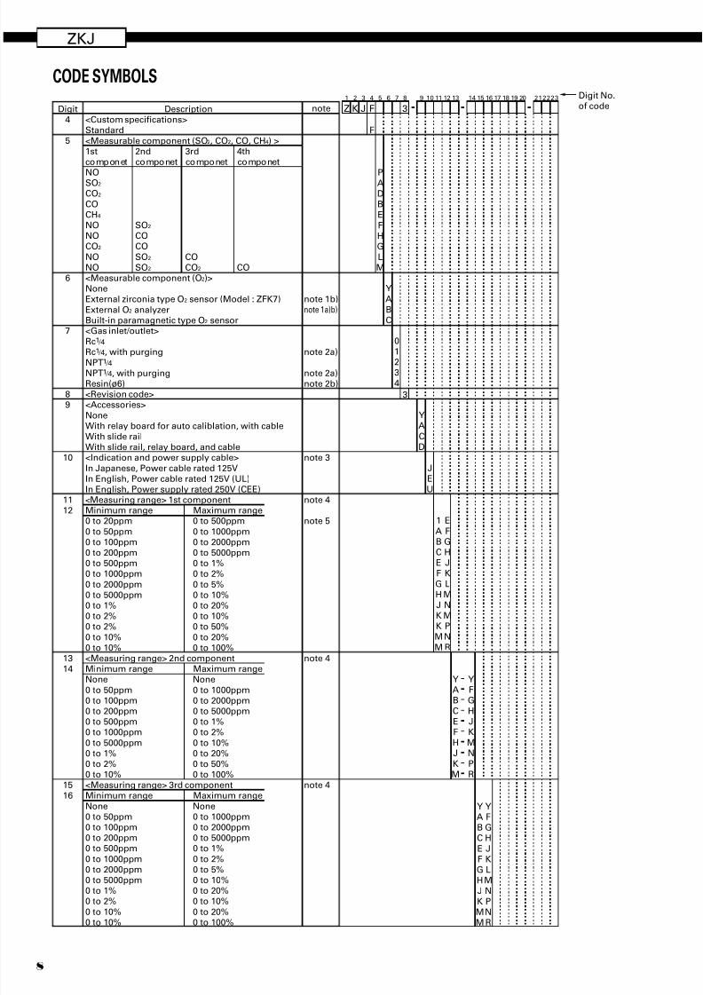
CODE SYMBOLS
Description
note 1b)note 1a)b)
note 2a)
note 2a)note 2b)
note 3
note 4
note 5
note 4
note 4
Digit4
5
6
7
89
10
1112
1314
1516
<Custom specifications>Standard
<Measurable component (SO2, CO2, CO, CH4) >1st 2nd 3rd 4thcomponet componet componet componet
NOSO2
CO2
COCH4
NO SO2
NO COCO2 CO
NO SO2 CONO SO2 CO2 CO<Measurable component (O2)>NoneExternal zirconia type O2 sensor (Model : ZFK7)
External O2 analyzerBuilt-in paramagnetic type O2 sensor<Gas inlet/outlet>Rc1 /4
Rc1 /4, with purgingNPT1 /4
NPT1 /4, with purgingResin(ø6)<Revision code><Accessories>
NoneWith relay board for auto caliblation, with cableWith slide railWith slide rail, relay board, and cable<Indication and power supply cable>
In Japanese, Power cable rated 125VIn English, Power cable rated 125V (UL)In English, Power supply rated 250V (CEE)
<Measuring range> 1st component Minimum range Maximum range
0 to 20ppm 0 to 500ppm0 to 50ppm 0 to 1000ppm0 to 100ppm 0 to 2000ppm0 to 200ppm 0 to 5000ppm0 to 500ppm 0 to 1%0 to 1000ppm 0 to 2%
0 to 2000ppm 0 to 5%0 to 5000ppm 0 to 10%0 to 1% 0 to 20%0 to 2% 0 to 10%0 to 2% 0 to 50%
0 to 10% 0 to 20%0 to 10% 0 to 100%<Measuring range> 2nd componentMinimum range Maximum rangeNone None
0 to 50ppm 0 to 1000ppm
0 to 100ppm 0 to 2000ppm0 to 200ppm 0 to 5000ppm0 to 500ppm 0 to 1%0 to 1000ppm 0 to 2%
0 to 5000ppm 0 to 10%0 to 1% 0 to 20%0 to 2% 0 to 50%0 to 10% 0 to 100%<Measuring range> 3rd componentMinimum range Maximum range
None None0 to 50ppm 0 to 1000ppm0 to 100ppm 0 to 2000ppm0 to 200ppm 0 to 5000ppm0 to 500ppm 0 to 1%
0 to 1000ppm 0 to 2%
0 to 2000ppm 0 to 5%0 to 5000ppm 0 to 10%0 to 1% 0 to 20%0 to 2% 0 to 10%
0 to 10% 0 to 20%0 to 10% 0 to 100%
F
PADBE
FHGLM
Y
ABC
0
123
4
3
Y A
CD
1ABCEF
GHJKKM
M
Y A
BCEFHJ
KM
4 5 6 71 2 3
Z K J F 3
8 9 10 11 12 13 14 15 16 17 18 19 20
EFGHJK
LMNMPN
R
Y F
GHJKMN
PR
Y ABC
EF
GHJ
KMM
Y FGH
JK
LMN
PNR
212223 Digit No.of code
JEU
note
7/28/2019 Fuji NDIR Analyzerzkj.pdf
http://slidepdf.com/reader/full/fuji-ndir-analyzerzkjpdf 9/209
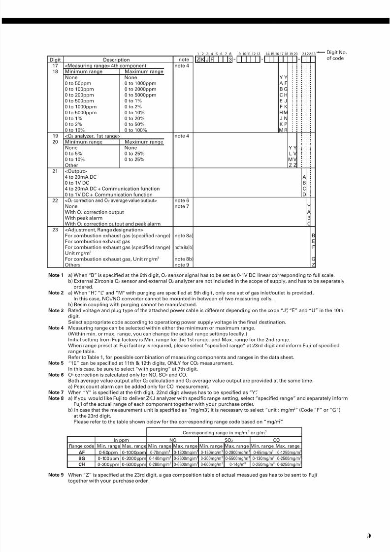
Digit1718
19
20
21
22
23
<Measuring range> 4th componentMinimum range Maximum range
None None0 to 50ppm 0 to 1000ppm0 to 100ppm 0 to 2000ppm
0 to 200ppm 0 to 5000ppm0 to 500ppm 0 to 1%
0 to 1000ppm 0 to 2%0 to 5000ppm 0 to 10%0 to 1% 0 to 20%0 to 2% 0 to 50%0 to 10% 0 to 100%
<O2 analyzer, 1st range>Minimum range Maximum rangeNone None0 to 5% 0 to 25%0 to 10% 0 to 25%
Other<Output>4 to 20mA DC0 to 1V DC4 to 20mA DC + Communication function
0 to 1V DC + Communication function<O2 correction and O2 average value output>
NoneWith O2 correction outputWith peak alarmWith O2 correction output and peak alarm
<Adjustment, Range designation>For combustion exhaust gas (specified range)For combustion exhaust gasFor combustion exhaust gas (specified range)Unit mg/m3
For combustion exhaust gas, Unit mg/m3
Others
Descriptionnote 4
note 4
note 6note 7
note 8a)
note 8a)b)
note 8b)
note 9
Y LMZ
ABC
D
BEF
GZ
Y AB
CEFHJK
M
4 5 6 71 2 3
Z K J F 3
8 9 10 11 12 13 14 15 16 17 18 19 20
Y FG
HJKMNP
R
Y VVZ
Y
ABC
212223 Digit No.of code
Note 1 a) When “B” is specified at the 6th digit, O2 sensor signal has to be set as 0-1V DC linear corresponding to full scale.b) External Zirconia O2 sensor and external O2 analyzer are not included in the scope of supply, and has to be separately
ordered.
Note 2 a) When “H”, “L” and “M" with purging are specified at 5th digit, only one set of gas inlet/outlet is provided.In this case, NO2 /NO converter cannot be mounted in between of two measuring cells.
b) Resin coupling with purging cannot be manufactued.
Note 3 Rated voltage and plug type of the attached power cable is different depending on the code “J”, “E” and “U” in the 10thdigit.
Select appropriate code according to operationg power supply voltage in the final destination.Note 4 Measuring range can be selected within either the minimum or maximum range.
(Within min. or max. range, you can change the actual range settings locally.)Initial setting from Fuji factory is Min. range for the 1st range, and Max. range for the 2nd range.When range preset at Fuji factory is required, please select “specified range” at 23rd digit and inform Fuji of specifiedrange table.
Refer to Table 1, for possible combination of measuring components and ranges in the data sheet.Note 5 “1E” can be specified at 11th & 12th digits, ONLY for CO2 measurement.
In this case, be sure to select “with purging” at 7th digit.
Note 6 O2 correction is calculated only for NO, SO2 and CO.Both average value output after O2 calculation and O2 average value output are provided at the same time.
a) Peak count alarm can be added only for CO measurement.Note 7 When “Y” is specified at the 6th digit, 22nd digit always has to be specified as “Y”.
Note 8 a) If you would like Fuji to deliver ZKJ analyzer with specific range setting, select “specified range” and separately informFuji of the actual range of each component together with your purchase order.
b) In case that the measurement unit is specified as “mg/m3”, it is necessary to select “unit : mg/m3” (Code “F” or “G”)
at the 23rd digit.Please refer to the table shown below for the corresponding range code based on “mg/m3”.
note
Note 9 When “Z” is specified at the 23rd digit, a gas composition table of actual measued gas has to be sent to Fujitogether with your purchase order.
Min. range Max. range Min. range Max. range Min. range Max. range Min. range Max. range
AF 0-50ppm 0-1000ppm
BG 0-100ppm 0-2000ppm
CH 0-200ppm 0-5000ppm
0-70mg/m3
0-140mg/m3
0-280mg/m3
0-1300mg/m3
0-2600mg/m3
0-6600mg/m3
0-150mg/m3
0-300mg/m3
0-600mg/m3
0-2800mg/m3
0-5500mg/m3
0-14g/m3
0-65mg/m3
0-130mg/m3
0-250mg/m3
0-1250mg/m3
0-2500mg/m3
0-6250mg/m3
Corresponding range in mg/m3 or g/m3
Range code
In ppm NO SO2 CO
7/28/2019 Fuji NDIR Analyzerzkj.pdf
http://slidepdf.com/reader/full/fuji-ndir-analyzerzkjpdf 10/20
ZKJ
10
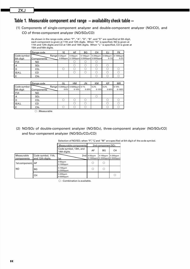
Table 1. Measurable component and range – availability check table –
(1) Components of single-component analyzer and double-component analyzer (NO/CO), and
CO of three-component analyzer (NO/SO2 /CO)
(2) NO/SO2 of double-component analyzer (NO/SO2), three-component analyzer (NO/SO2 /CO)
and four-component analyzer (NO/SO2 /CO2 /CO)
2ndMeasurable
components 1st
1st component,
NO
AFCode symbol, 13th, and
14th digits.
0-50ppm
0-1000ppm
0-100ppm
0-2000ppm
0-200ppm
0-5000ppm
BG CH
0-50ppm
0-1000ppm
0-100ppm
0-2000ppm
0-200ppm
0-5000ppmCH
BG
AF
Code symbol, 11th,
and 12th digits.
2nd component SO2Measurable components
Selection of NO/SO2 when “F”, “L”, and “M” are specified at 5th digit of the code symbol.
: Combination is available.
Range code
RangeCode symbol5th digit Components
EJ FK
D CO2
E CH4
B,H,L CO
P,H NO
A SO2
AF1E
0-20ppm
0-500ppm
0-50ppm
0-1000ppm
0-100ppm
0-2000ppm
0-200ppm
0-5000ppm
0-500ppm
0-1%
0-1000ppm
0-2%
BG CH
As shown in the range code, when “P”, “A”, “D”, “B”, and “E” are specified at 5th digit,each component is given at 11th and 12th digits. When “H” is specified, NO is given at11th and 12th digits and CO at 13th and 14th digits. When “L” is specified, CO is given at
15th and16th digits.
Range code
RangeCode symbol5th digit Components
D CO2
E CH4
B,H,L CO
P,H NO
A SO2
: Measurable
GL HM JN KM KP MR
0-2000ppm
0-5%
0-5000ppm
0-10%
0-1%
0-20%
0-2%
0-10%
0-2%
0-50%
0-10%
0-100%
7/28/2019 Fuji NDIR Analyzerzkj.pdf
http://slidepdf.com/reader/full/fuji-ndir-analyzerzkjpdf 11/2011
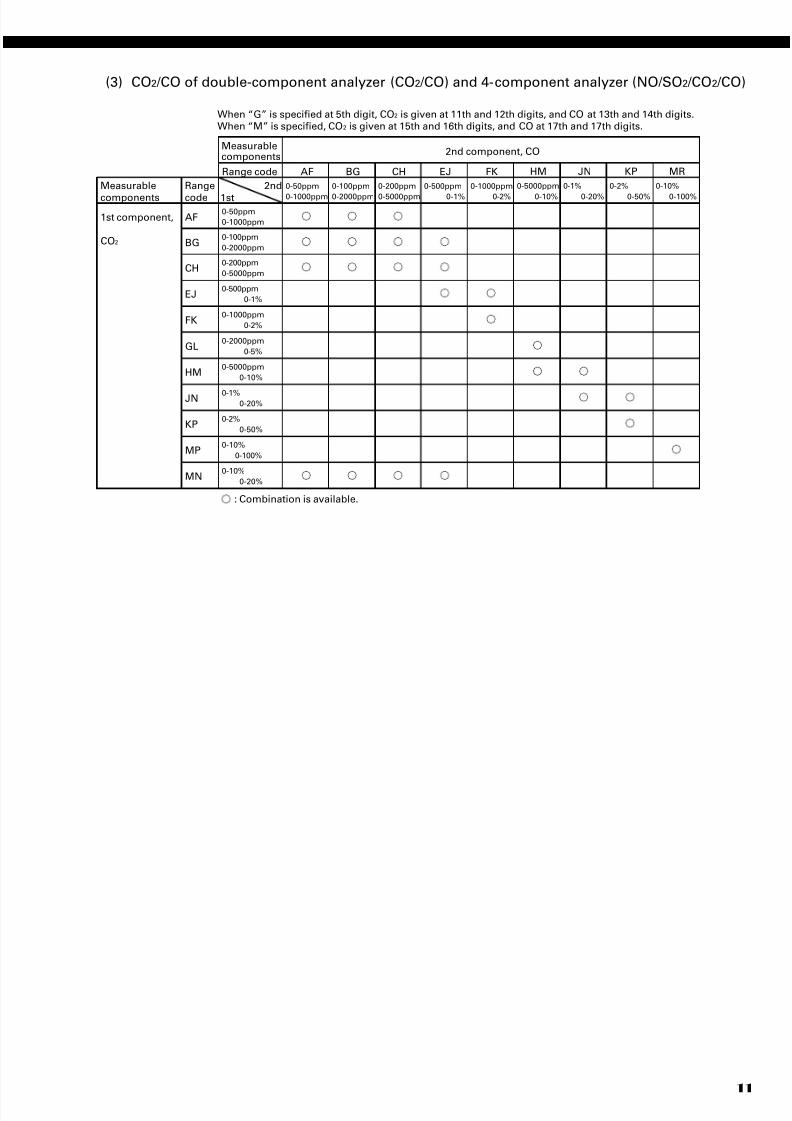
(3) CO2 /CO of double-component analyzer (CO2 /CO) and 4-component analyzer (NO/SO2 /CO2 /CO)
2ndMeasurable
components 1st
1st component,
CO2
AFRange code
0-50ppm
0-1000ppm
0-100ppm
0-2000ppm
0-200ppm
0-5000ppm
BG CH
When “G” is specified at 5th digit, CO2 is given at 11th and 12th digits, and CO at 13th and 14th digits.When “M” is specified, CO2 is given at 15th and 16th digits, and CO at 17th and 17th digits.
0-50ppm
0-1000ppm
0-100ppm
0-2000ppm
0-200ppm
0-5000ppmCH
BG
AF
Range
code
2nd component, COMeasurablecomponents
EJ
0-500ppm
0-1%
FK
0-1000ppm
0-2%
0-500ppm
0-1%EJ
0-1000ppm
0-2%FK
0-2000ppm
0-5%GL
0-5000ppm
0-10%HM
0-1%0-20%
JN
0-2%
0-50%KP
0-10%
0-100%MP
0-10%
0-20%MN
HM
0-5000ppm
0-10%
JN
0-1%
0-20%
KP
0-2%
0-50%
MR
0-10%
0-100%
: Combination is available.
7/28/2019 Fuji NDIR Analyzerzkj.pdf
http://slidepdf.com/reader/full/fuji-ndir-analyzerzkjpdf 12/20
ZKJ
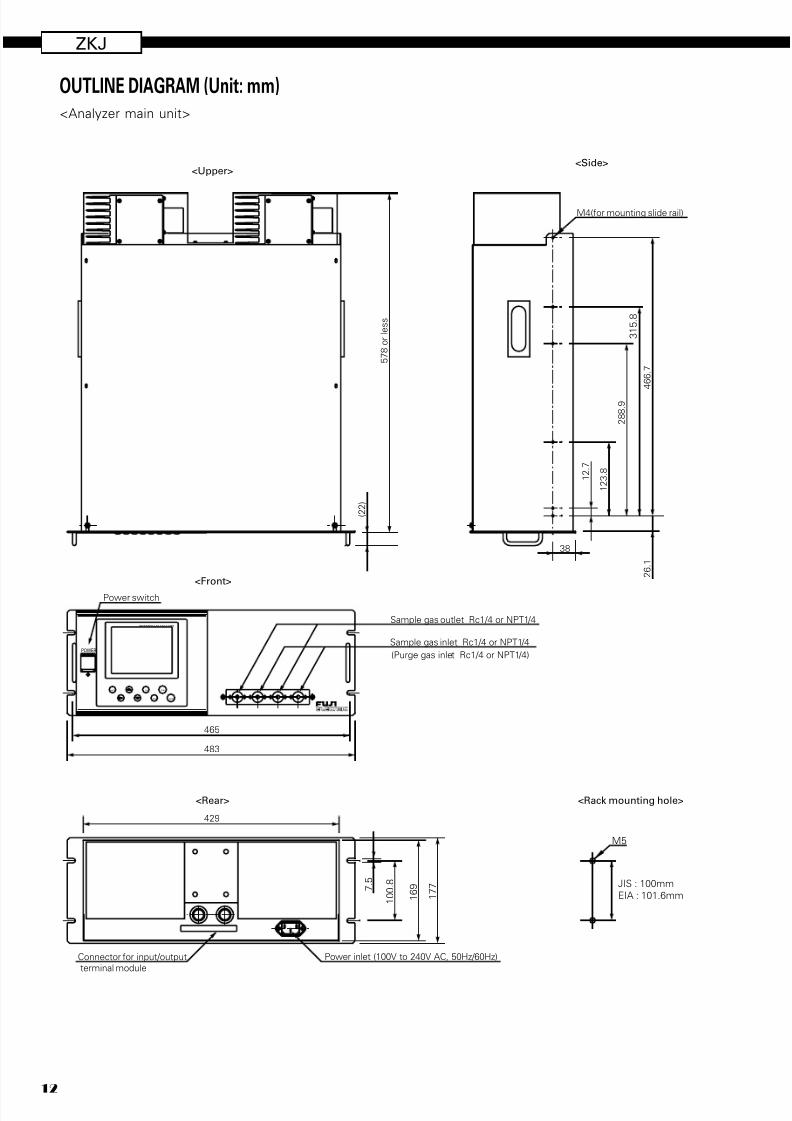
12
OUTLINE DIAGRAM (Unit: mm)<Analyzer main unit>
5 7 8
o r l e s s
M4(for mounting slide rail)
1 2 .
7
1 2 3 .
8
2 8 8 .
9
3 1 5 .
8
4 6 6 .
7
7 . 5
1 0 0 .
8
Sample gas inlet Rc1/4 or NPT1/4
(Purge gas inlet Rc1/4 or NPT1/4)
Sample gas outlet Rc1/4 or NPT1/4
1 7 7
( 2 2 )
2 6 .
1
38
Connector for input/output
terminal module
465
483
Power inlet (100V to 240V AC, 50Hz/60Hz)
429
SPANENT
ZEROESCMODE
POWER
<Side>
<Front>
<Rear>
<Upper>
INFRARED GAS ANALYZER
1 6 9
Power switch
<Rack mounting hole>
M5
JIS : 100mm
EIA : 101.6mm
7/28/2019 Fuji NDIR Analyzerzkj.pdf
http://slidepdf.com/reader/full/fuji-ndir-analyzerzkjpdf 13/2013
( 1 4 0 )
1 2
1 6 4
1 5 4
5
( 5 4 .
5 ) 2
9
316
6-ø4.5hole
150 150 8
(280)
100030
8
Terminalblock
<TN1>
Terminalblock
<TN2>
Terminalblock
<TN3>
Terminalblock
<TN4>
Terminalblock
<TN5>
Connector
<CN3>
Screw terminals M3.5
<Input / output terminal module>
Input / output terminal
module connector
<Cable for connecting input / output terminal>
<Dimensions for mounting input / output terminal module>
(Accessory)
(Accessory)
Mounting hole
302
150 150
1 5 4
1 4 2
M4 screw
Cut M4 screw holes at 6 positions.Drill a rectangular hole of 302 142mm or more in the center.
7/28/2019 Fuji NDIR Analyzerzkj.pdf
http://slidepdf.com/reader/full/fuji-ndir-analyzerzkjpdf 14/20
ZKJ
14
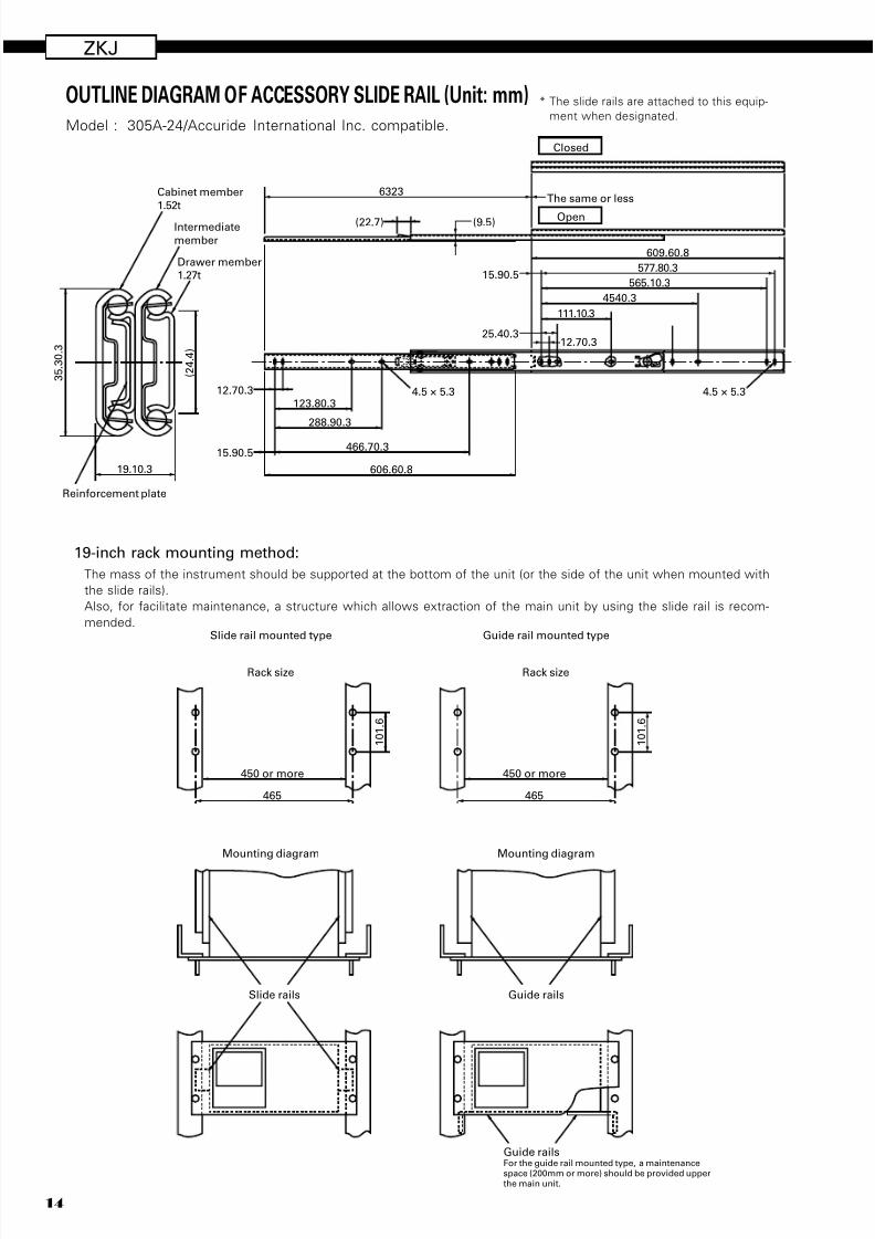
19-inch rack mounting method:
The mass of the instrument should be supported at the bottom of the unit (or the side of the unit when mounted with
the slide rails).
Also, for facilitate maintenance, a structure which allows extraction of the main unit by using the slide rail is recom-
mended.
OUTLINE DIAGRAM OF ACCESSORY SLIDE RAIL (Unit: mm)Model : 305A-24/Accuride International Inc. compatible.
3 5 .
3 0 .
3
19.10.3 606.60.8
6323The same or less
Closed
466.70.3
288.90.3
111.10.3
4540.3
565.10.3
577.80.3
609.60.8
4.5 × 5.3 4.5 × 5.3123.80.3
25.40.3
15.90.5
12.70.3
12.70.3
(22.7) (9.5)
15.90.5
( 2 4 . 4
)
Reinforcement plate
Cabinet member
1.52t
Drawer member
1.27t
Intermediate
member
Open
465
450 or more
1 0 1 .
6
465
450 or more
1 0 1 .
6
Slide rail mounted type
Rack size
Guide rail mounted type
Rack size
Mounting diagram
Slide rails
Mounting diagram
Guide rails
Guide railsFor the guide rail mounted type, a maintenancespace (200mm or more) should be provided upperthe main unit.
* The slide rails are attached to this equip-
ment when designated.
7/28/2019 Fuji NDIR Analyzerzkj.pdf
http://slidepdf.com/reader/full/fuji-ndir-analyzerzkjpdf 15/2015
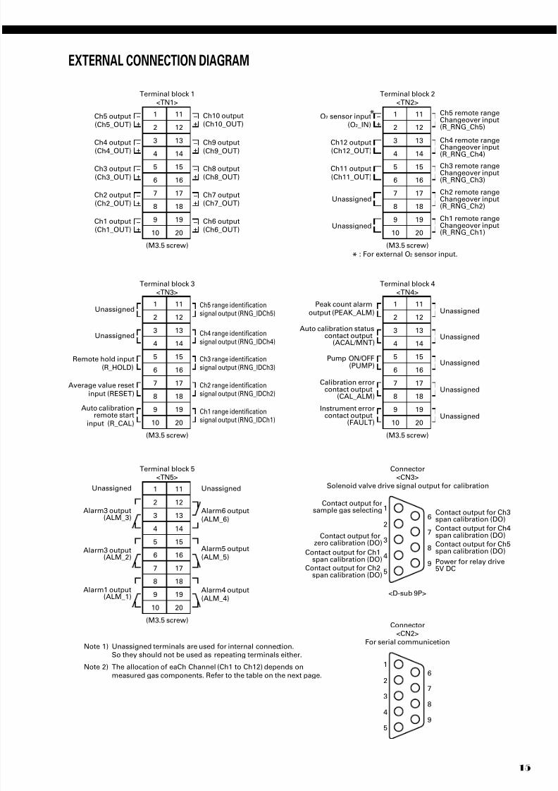
Terminal block 1
<TN1>
11
12
13
14
15
16
17
18
19
20
1
2
3
4
5
6
7
8
9
10
(M3.5 screw)
Ch9 output
(Ch9_OUT)
Ch10 output(Ch10_OUT)
Ch8 output(Ch8_OUT)
Ch7 output(Ch7_OUT)
Ch6 output(Ch6_OUT)
Ch1 output(Ch1_OUT)
Ch2 output
(Ch2_OUT)
Ch3 output
(Ch3_OUT)
Ch4 output(Ch4_OUT)
Ch5 output(Ch5_OUT) +
–+–
+–
+–
+–
+–
+–
+–
+–
+–
+–
Terminal block 2
<TN2>
11
12
13
14
15
16
17
18
19
20
1
2
3
4
5
6
7
8
9
10
(M3.5 screw)
Ch4 remote rangeChangeover input(R_RNG_Ch4)
Ch5 remote rangeChangeover input(R_RNG_Ch5)
Ch3 remote rangeChangeover input(R_RNG_Ch3)
Ch2 remote rangeChangeover input(R_RNG_Ch2)
Ch1 remote rangeChangeover input(R_RNG_Ch1)
Ch12 output(Ch12_OUT)
Ch11 output
(Ch11_OUT)
Unassigned
Unassigned
O2 sensor input(O2_IN)
*
*
Terminal block 3
<TN3>
11
12
13
14
15
16
17
18
19
20
1
2
3
4
5
6
7
8
9
10
(M3.5 screw)
Ch4 range identificationsignal output (RNG_IDCh4)
Ch5 range identificationsignal output (RNG_IDCh5)
Ch3 range identificationsignal output (RNG_IDCh3)
Ch2 range identificationsignal output (RNG_IDCh2)
Ch1 range identificationsignal output (RNG_IDCh1)
Auto calibration
remote startinput (R_CAL)
Average value resetinput (RESET)
Remote hold input(R_HOLD)
Unassigned
Unassigned
Terminal block 5<TN5>
11
12
13
14
15
16
17
18
19
20
1
2
3
4
5
6
7
8
9
10
(M3.5 screw)
Unassigned
Alarm6 output
(ALM_6)
Alarm5 output
(ALM_5)
Alarm4 output(ALM_4)
Alarm3 output(ALM_3)
Alarm3 output(ALM_2)
Alarm1 output(ALM_1)
Unassigned
Terminal block 4
<TN4>
11
12
13
14
15
16
17
18
19
20
1
2
3
4
5
6
7
8
9
10
(M3.5 screw)
Unassigned
Unassigned
Unassigned
Auto calibration statuscontact output
(ACAL/MNT)
Calibration errorcontact output
(CAL_ALM)
Unassigned
Unassigned
Note 1) Unassigned terminals are used for internal connection.So they should not be used as repeating terminals either.
Note 2) The allocation of eaCh Channel (Ch1 to Ch12) depends on
measured gas components. Refer to the table on the next page.
: For external O2 sensor input.
Instrument error
contact output(FAULT)
Pump ON/OFF(PUMP)
Peak count alarmoutput (PEAK_ALM)
Connector<CN3>
Solenoid valve drive signal output for calibration
<D-sub 9P>
Contact output forzero calibration (DO)
Contact output forsample gas selecting
Contact output for Ch1span calibration (DO)
Contact output for Ch2span calibration (DO)
Contact output for Ch3span calibration (DO)
Contact output for Ch4span calibration (DO)
Contact output for Ch5
span calibration (DO)Power for relay drive5V DC
1
2
3
4
5
6
7
8
9
Connector<CN2>
For serial communicetion
1
2
3
4
5
6
7
8
9
EXTERNAL CONNECTION DIAGRAM
7/28/2019 Fuji NDIR Analyzerzkj.pdf
http://slidepdf.com/reader/full/fuji-ndir-analyzerzkjpdf 16/20
ZKJ
16
CN1
C N 9
CN2 CN3 CN4 CN5
CN13
CN6 CN7 CN8
7 5 6 5
150
140
15 or less
4.5Mounting hole
CN1CN9
Solenoid valvedriving power
Solenoid valve
CN2
CN13
CN3
Reserved
For switchingsample
CN3
For zero gas
Relay board
I/O terminal module
Dedicated cable (D-sub 9-pin straight cable 1.5 m)
For span gas
CN4 CN5 CN6 CN7 CN8
CH1 CH2 CH3 CH4 CH5
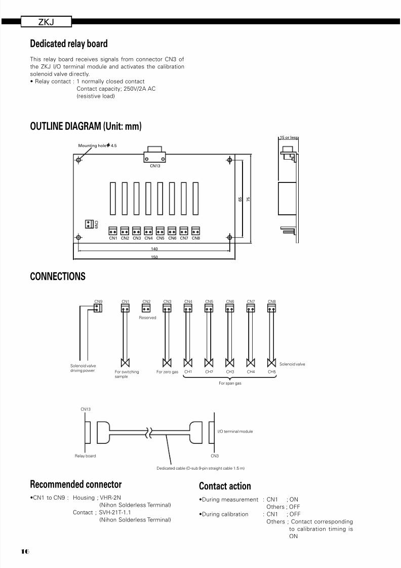
This relay board receives signals from connector CN3 of
the ZKJ I/O terminal module and activates the calibration
solenoid valve directly.
• Relay contact : 1 normally closed contact
Contact capacity; 250V/2A AC
(resistive load)
OUTLINE DIAGRAM (Unit: mm)
Dedicated relay board
CONNECTIONS
Recommended connector
•CN1 to CN9 : Housing ; VHR-2N(Nihon Solderless Terminal)
Contact ; SVH-21T-1.1
(Nihon Solderless Terminal)
Contact action•During measurement : CN1 ; ON
Others ; OFF
•During calibration : CN1 ; OFF
Others ; Contact corresponding
to calibration timing is
ON
7/28/2019 Fuji NDIR Analyzerzkj.pdf
http://slidepdf.com/reader/full/fuji-ndir-analyzerzkjpdf 17/2017
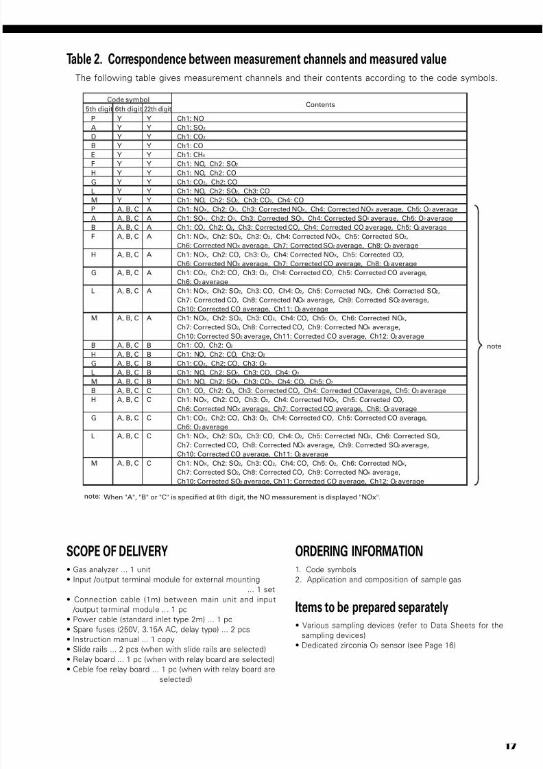
Table 2. Correspondence between measurement channels and measured valueThe following table gives measurement channels and their contents according to the code symbols.
P
A
D
B
E
F
H
G
L
M
P
A
B
F
H
G
L
M
B
H
G
L
M
B
H
G
L
M
Y
Y
Y
Y
Y
Y
Y
Y
Y
Y
A, B, C
A, B, C
A, B, C
A, B, C
A, B, C
A, B, C
A, B, C
A, B, C
A, B, C
A, B, C
A, B, C
A, B, C
A, B, C
A, B, C
A, B, C
A, B, C
A, B, C
A, B, C
Ch1: NO
Ch1: SO2
Ch1: CO2
Ch1: CO
Ch1: CH4
Ch1: NO, Ch2: SO2
Ch1: NO, Ch2: CO
Ch1: CO2, Ch2: CO
Ch1: NO, Ch2: SO2, Ch3: CO
Ch1: NO, Ch2: SO2, Ch3: CO2, Ch4: CO
Ch1: NOX, Ch2: O2, Ch3: Corrected NOX, Ch4: Corrected NOX average, Ch5: O2 average
Ch1: SO2, Ch2: O2, Ch3: Corrected SO2, Ch4: Corrected SO2 average, Ch5: O2 average
Ch1: CO, Ch2: O2, Ch3: Corrected CO, Ch4: Corrected CO average, Ch5: O2 average
Ch1: NOX, Ch2: SO2, Ch3: O2, Ch4: Corrected NOX, Ch5: Corrected SO2,
Ch6: Corrected NOX average, Ch7: Corrected SO2 average, Ch8: O2 average
Ch1: NOX, Ch2: CO, Ch3: O2, Ch4: Corrected NOX, Ch5: Corrected CO,
Ch6: Corrected NOX average, Ch7: Corrected CO average, Ch8: O2 average
Ch1: CO2, Ch2: CO, Ch3: O2, Ch4: Corrected CO, Ch5: Corrected CO average,
Ch6: O2 average
Ch1: NOX, Ch2: SO2, Ch3: CO, Ch4: O2, Ch5: Corrected NOX, Ch6: Corrected SO2,
Ch7: Corrected CO, Ch8: Corrected NOX average, Ch9: Corrected SO2 average,
Ch10: Corrected CO average, Ch11: O2 average
Ch1: NOX, Ch2: SO2, Ch3: CO2, Ch4: CO, Ch5: O2, Ch6: Corrected NOX,
Ch7: Corrected SO2, Ch8: Corrected CO, Ch9: Corrected NOX average,
Ch10: Corrected SO2 average, Ch11: Corrected CO average, Ch12: O2 average
Ch1: CO, Ch2: O2
Ch1: NO, Ch2: CO, Ch3: O2
Ch1: CO2, Ch2: CO, Ch3: O2
Ch1: NO, Ch2: SO2, Ch3: CO, Ch4: O2
Ch1: NO, Ch2: SO2, Ch3: CO2, Ch4: CO, Ch5: O2
Ch1: CO, Ch2: O2, Ch3: Corrected CO, Ch4: Corrected CO average, Ch5: O2 average
Ch1: NOX, Ch2: CO, Ch3: O2, Ch4: Corrected NOX, Ch5: Corrected CO,
Ch6: Corrected NOX average, Ch7: Corrected CO average, Ch8: O2 average
Ch1: CO2, Ch2: CO, Ch3: O2, Ch4: Corrected CO, Ch5: Corrected CO average,
Ch6: O2 average
Ch1: NOX, Ch2: SO2, Ch3: CO, Ch4: O2, Ch5: Corrected NOX, Ch6: Corrected SO2,
Ch7: Corrected CO, Ch8: Corrected NOX average, Ch9: Corrected SO2 average,
Ch10: Corrected CO average, Ch11: O2 average
Ch1: NOX, Ch2: SO2, Ch3: CO2, Ch4: CO, Ch5: O2, Ch6: Corrected NOX,
Ch7: Corrected SO2, Ch8: Corrected CO, Ch9: Corrected NOX average,
Ch10: Corrected SO2 average, Ch11: Corrected CO average, Ch12: O2 average
Code symbolContents
5th digit 6th digit
Y
Y
Y
Y
Y
Y
Y
Y
Y
Y
A
A
A
A
A
A
A
A
B
B
B
B
B
C
C
C
C
C
22th digit
note
note: When "A", "B" or "C" is specified at 6th digit, the NO measurement is displayed "NOx".
SCOPE OF DELIVERY• Gas analyzer ... 1 unit
• Input /output terminal module for external mounting
... 1 set
• Connection cable (1m) between main unit and input
/output terminal module .. . 1 pc
• Power cable (standard inlet type 2m) ... 1 pc
• Spare fuses (250V, 3.15A AC, delay type) ... 2 pcs
• Instruction manual ... 1 copy
• Slide rails ... 2 pcs (when with slide rails are selected)
• Relay board ... 1 pc (when with relay board are selected)
• Ceble foe relay board ... 1 pc (when with relay board are
selected)
ORDERING INFORMATION1. Code symbols
2. Application and composition of sample gas
Items to be prepared separately• Various sampling devices (refer to Data Sheets for the
sampling devices)
• Dedicated zirconia O2 sensor (see Page 16)
7/28/2019 Fuji NDIR Analyzerzkj.pdf
http://slidepdf.com/reader/full/fuji-ndir-analyzerzkjpdf 18/20
ZKJ
18
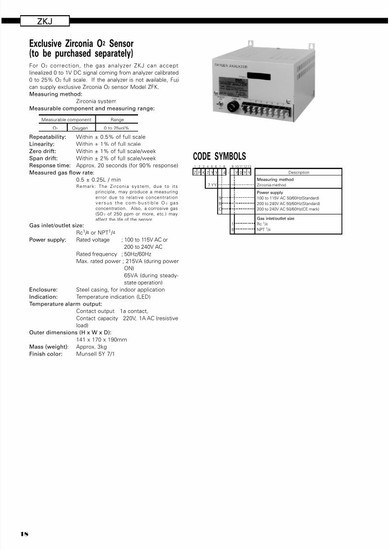
For O2 correction, the gas analyzer ZKJ can accept
linealized 0 to 1V DC signal coming from analyzer calibrated
0 to 25% O2 full scale. If the analyzer is not available, Fuji
can supply exclusive Zirconia O2 sensor Model ZFK.
Measuring method:Zirconia system
Measurable component and measuring range:
Repeatability: Within ± 0.5% of full scale
Linearity: Within ± 1% of full scale
Zero drift: Within ± 1% of full scale/week
Span drift: Within ± 2% of full scale/week
Response time: Approx. 20 seconds (for 90% response)
Measured gas flow rate:
0.5 ± 0.25L / minRemark: The Zirconia system, due to i ts
principle, may produce a measuringerror due to relative concentration
ve rsus the com-bus t i b l e O 2 gas
concentration. Also, a corrosive gas
(SO 2 of 250 ppm or more, etc.) may
affect the life of the sensor.
Gas inlet/outlet size:
Rc1 / 4 or NPT1 / 4
Power supply: Rated voltage ; 100 to 115V AC or
200 to 240V AC
Rated frequency ; 50Hz/60Hz
Max. rated power ; 215VA (during power
ON)
65VA (during steady-
state operation)
Enclosure: Steel casing, for indoor applicationIndication: Temperature indication (LED)
Temperature alarm output:
Contact output 1a contact,
Contact capacity 220V, 1A AC (resistive
load)
Outer dimensions (H x W x D):
141 x 170 x 190mm
Mass {weight}: Approx. 3kg
Finish color: Munsell 5Y 7/1
Exclusive Zirconia O2 Sensor(to be purchased separately)
Measurable component Range
O2 Oxygen 0 to 25vol%
CODE SYMBOLS
-4KFZ YY7
9
Y
10
0
11
Y
12
Y
1321 3 4 5 6 7 8
Description
7 Y Y
9
B
C
Measuring method
Zirconia method
Power supply100 to 115V AC 50/60Hz(Standard)
200 to 240V AC 50/60Hz(Standard)
200 to 240V AC 50/60Hz(CE mark)
1
8
Gas inlet/outlet size
Rc 1 / 4
NPT 1 / 4
7/28/2019 Fuji NDIR Analyzerzkj.pdf
http://slidepdf.com/reader/full/fuji-ndir-analyzerzkjpdf 19/2019
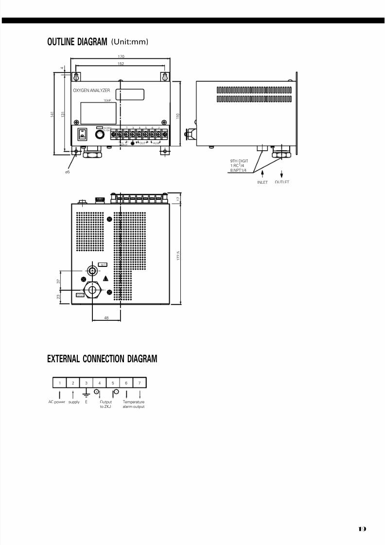
1 2 3 4 5 6 7
AC power supply E Output
to ZKJ
Temperature
alarm output
+ -
3 4 5 6 72
ALMAC
TEMP.
1
OUTLET
AC250VT3.15A
ø5
OXYGEN ANALYZER
INPUT
INLET
9TH DIGIT
1:RC1 /4
8:NPT1/4
OUTLET
OUT
170
152
1 3 1
1 7 2 .
5
1 7
1 1 0
4
1 4 1
S F
E U
NL
2 3
INLET
3 7
48
EXTERNAL CONNECTION DIAGRAM
OUTLINE DIAGRAM (Unit:mm)

7/28/2019 Fuji NDIR Analyzerzkj.pdf
http://slidepdf.com/reader/full/fuji-ndir-analyzerzkjpdf 20/20
Sales Div. III, International Sales Group
Global Business Group
Gate City Ohsaki, East Tower, 11-2, Osaki 1-chome,
Shinagawa-ku, Tokyo 141-0032, Japan
http://www.fesys.co.jp/eng
Phone: 81-3-5435-7280, 7281 Fax: 81-3-5435-7425
http://www.fic-net.jp/eng
Caution on Safety
*Before using this product, be sure to read its instruction manual in advance.
ZKJ