발전설비열유체기술 - engsoft.co.kr · • 연소공학 • 회전체동력학 •...
107
1. Thermodynamics for Gas Turbines 1 /107 Gas Turbines for Power Plants 발전설비 열유체기술 발전설비 열역학 발전용 가스터빈 754 MJ/s (100%) 205 MW (27.2%) 203 160 119 MW = 482 MW (63.9%) 277 MW (Net Output) (36.7%) 272 MJ/s (36.1%) 증기터빈 열유체기술 발전설비 입문 - 열유체기술
Transcript of 발전설비열유체기술 - engsoft.co.kr · • 연소공학 • 회전체동력학 •...

1. Thermodynamics for Gas Turbines 1 /107Gas Turbines for Power Plants
발전설비 열유체기술
발전설비 열역학
발전용 가스터빈
754 MJ/s
(100%)
205 MW
(27.2%)
203 160 119 MW = 482 MW (63.9%)
277 MW (Net Output)
(36.7%)
272 MJ/s
(36.1%)
증기터빈 열유체기술
발전설비 입문 - 열유체기술

1. Thermodynamics for Gas Turbines 2 /107Gas Turbines for Power Plants
1. Thermodynamics for Gas Turbines
1. Thermodynamics for Gas Turbines 3 /107Gas Turbines for Power Plants
Power plantsResearchDevelopmentDesignManufacturingMaintenance
Fluid Mechanics
Thermo-dynamics
Heat Transfer
Solid Mechanics
Vibration
Rotor Dynamics
Material Science
Acoustics
Manufacturing Engineering
Mathematics
Numerical Analysis
Control System
Electrical Engineering
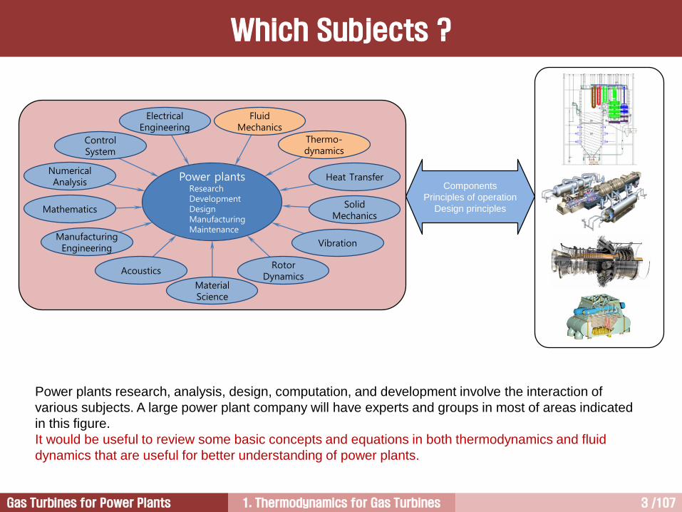
Power plants research, analysis, design, computation, and development involve the interaction of
various subjects. A large power plant company will have experts and groups in most of areas indicated
in this figure.
It would be useful to review some basic concepts and equations in both thermodynamics and fluid
dynamics that are useful for better understanding of power plants.
Components
Principles of operation
Design principles
Which Subjects ?

1. Thermodynamics for Gas Turbines 4 /107Gas Turbines for Power Plants
What is thermodynamics ? The science that studies the relationship between heat and work.
TH
TL
QL
W
QH
열기관
Thermodynamics [1/2]
?1) What is the maximum work output (W) that can be achieved for a given heat input (QH)? Thermal efficiency
2) How do we compare work with heat? Joule’s experimental work
3) What is the link between heat and work? The first law of thermodynamics
1. Thermodynamics for Gas Turbines 5 /107Gas Turbines for Power Plants
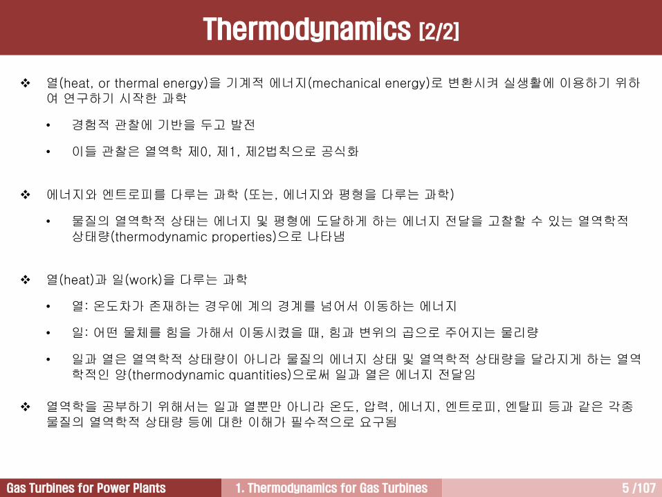
열(heat, or thermal energy)을 기계적 에너지(mechanical energy)로 변환시켜 실생활에 이용하기 위하여 연구하기 시작한 과학
• 경험적 관찰에 기반을 두고 발전
• 이들 관찰은 열역학 제0, 제1, 제2법칙으로 공식화
에너지와 엔트로피를 다루는 과학 (또는, 에너지와 평형을 다루는 과학)
• 물질의 열역학적 상태는 에너지 및 평형에 도달하게 하는 에너지 전달을 고찰할 수 있는 열역학적상태량(thermodynamic properties)으로 나타냄
열(heat)과 일(work)을 다루는 과학
• 열: 온도차가 존재하는 경우에 계의 경계를 넘어서 이동하는 에너지
• 일: 어떤 물체를 힘을 가해서 이동시켰을 때, 힘과 변위의 곱으로 주어지는 물리량
• 일과 열은 열역학적 상태량이 아니라 물질의 에너지 상태 및 열역학적 상태량을 달라지게 하는 열역학적인 양(thermodynamic quantities)으로써 일과 열은 에너지 전달임
열역학을 공부하기 위해서는 일과 열뿐만 아니라 온도, 압력, 에너지, 엔트로피, 엔탈피 등과 같은 각종물질의 열역학적 상태량 등에 대한 이해가 필수적으로 요구됨
Thermodynamics [2/2]
1. Thermodynamics for Gas Turbines 6 /107Gas Turbines for Power Plants
1. Power Plants
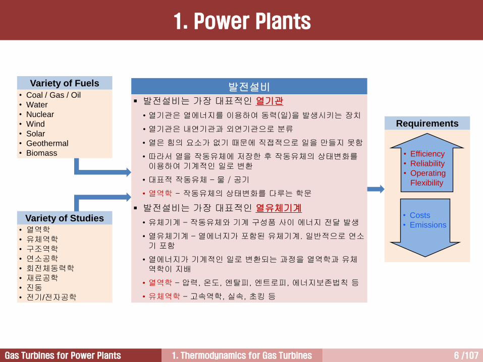
발전설비
발전설비는 가장 대표적인 열기관
• 열기관은 열에너지를 이용하여 동력(일)을 발생시키는 장치
• 열기관은 내연기관과 외연기관으로 분류
• 열은 힘의 요소가 없기 때문에 직접적으로 일을 만들지 못함
• 따라서 열을 작동유체에 저장한 후 작동유체의 상태변화를이용하여 기계적인 일로 변환
• 대표적 작동유체 – 물 / 공기
• 열역학 - 작동유체의 상태변화를 다루는 학문
발전설비는 가장 대표적인 열유체기계
• 유체기계 – 작동유체와 기계 구성품 사이 에너지 전달 발생
• 열유체기계 – 열에너지가 포함된 유체기계. 일반적으로 연소기 포함
• 열에너지가 기계적인 일로 변환되는 과정을 열역학과 유체역학이 지배
• 열역학 – 압력, 온도, 엔탈피, 엔트로피, 에너지보존법칙 등
• 유체역학 – 고속역학, 실속, 초킹 등
Requirements
• Efficiency
• Reliability
• Operating
Flexibility
• Costs
• Emissions
Variety of Fuels
• Coal / Gas / Oil
• Water
• Nuclear
• Wind
• Solar
• Geothermal
• Biomass
Variety of Studies
• 열역학• 유체역학• 구조역학• 연소공학• 회전체동력학• 재료공학• 진동• 전기/전자공학

1. Thermodynamics for Gas Turbines 7 /107Gas Turbines for Power Plants
Energy Conversion
1. Power Plants
Combustion Steam TBN GeneratorChemical
Energy
Thermal
Energy
Mechanical
Energy
Electrical
Energy
Fuel
Steam
Boiler
Steam Turbine Generator
Working Fluid
Transformer
2차 계통1차 계통
T
s
1
2
3
4qC
wTqB
qB
qB
wP
a
1. Thermodynamics for Gas Turbines 8 /107Gas Turbines for Power Plants
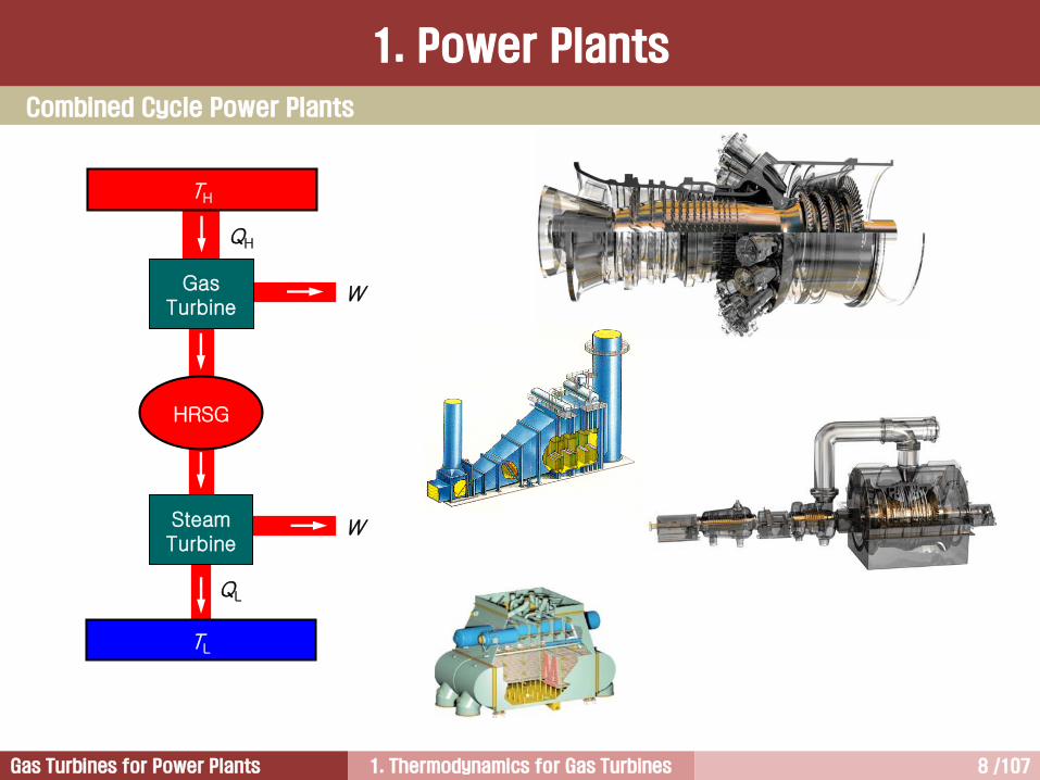
TH
TL
QL
W
QH
Gas Turbine
WSteamTurbine
HRSG
Combined Cycle Power Plants
1. Power Plants

1. Thermodynamics for Gas Turbines 9 /107Gas Turbines for Power Plants
계(system)경계(boundary)
주위(surrounding)
계(system):
• 해석 대상인 한 조각의 상태가 일정한 물질
• 해석 대상의 어떤 공간 영역
• 질량이나 에너지, 또는 이들 모두를 주위와 주고받음
주위(surrounding): 계 외부의 모든 것
경계(boundary):
• 계와 주위를 분리하는 두께가 없는 표면
• 물리적인 벽면이 경계가 될 수 있음
• 계의 경계는 움직임
작동유체(working fluids):
• 계 내부를 채우고 있거나 흐르는 물질
• 에너지를 저장할 수 있는 능력 보유
W
W
dx
공기경계
W (Weight)
pA
(Pressure force)
계 (System)
1. Power Plants
1. Thermodynamics for Gas Turbines 10 /107Gas Turbines for Power Plants
밀폐계 (Closed System)
1. Power Plants
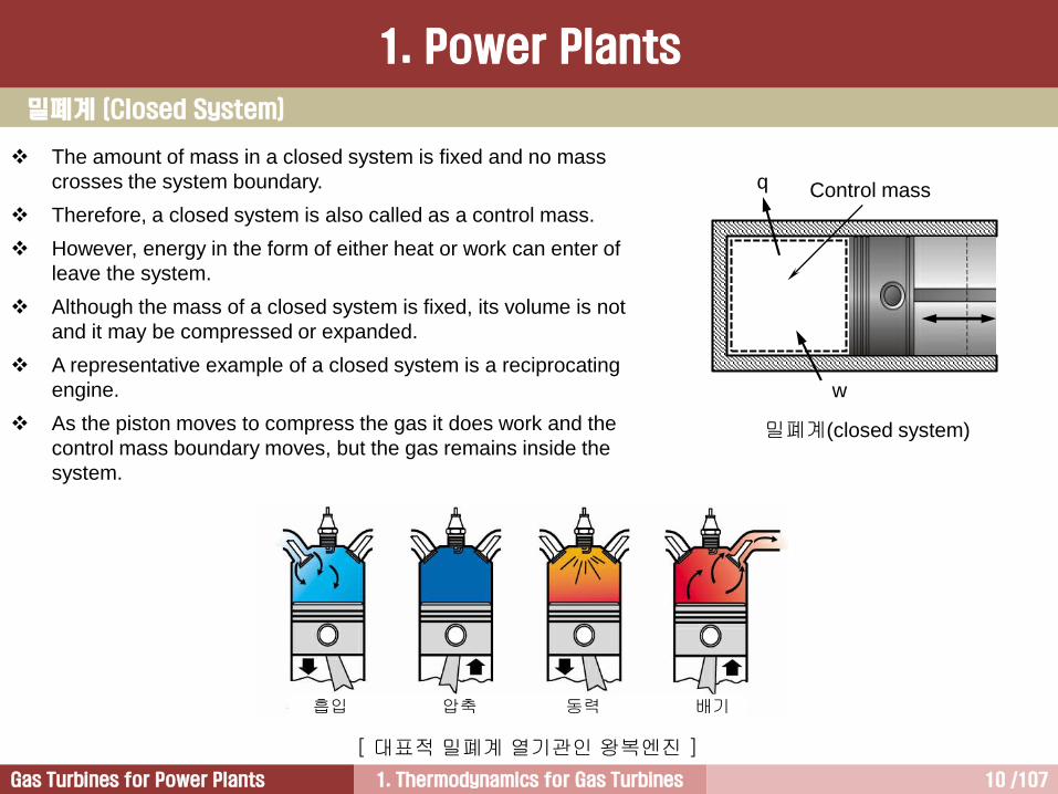
밀폐계(closed system)
흡입 압축 동력 배기
[ 대표적 밀폐계 열기관인 왕복엔진 ]
The amount of mass in a closed system is fixed and no mass
crosses the system boundary.
Therefore, a closed system is also called as a control mass.
However, energy in the form of either heat or work can enter of
leave the system.
Although the mass of a closed system is fixed, its volume is not
and it may be compressed or expanded.
A representative example of a closed system is a reciprocating
engine.
As the piston moves to compress the gas it does work and the
control mass boundary moves, but the gas remains inside the
system.
Control massq
w
1. Thermodynamics for Gas Turbines 11 /107Gas Turbines for Power Plants
개방계 (Open System)
1. Power Plants
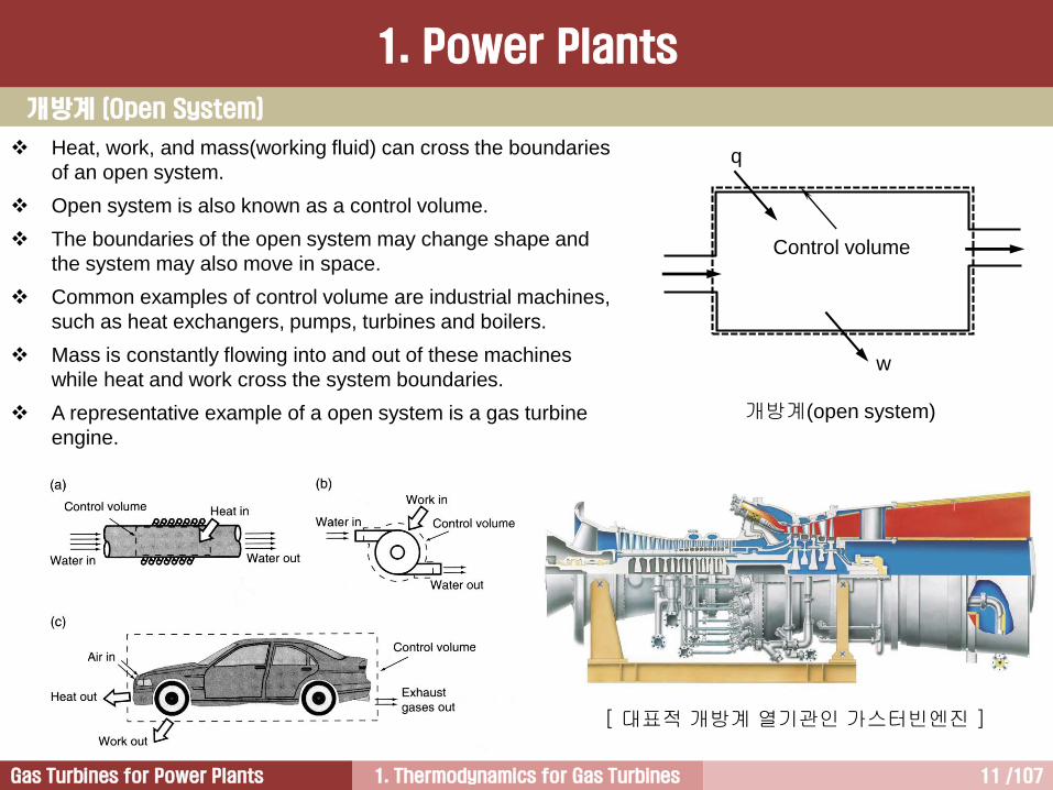
Heat, work, and mass(working fluid) can cross the boundaries
of an open system.
Open system is also known as a control volume.
The boundaries of the open system may change shape and
the system may also move in space.
Common examples of control volume are industrial machines,
such as heat exchangers, pumps, turbines and boilers.
Mass is constantly flowing into and out of these machines
while heat and work cross the system boundaries.
A representative example of a open system is a gas turbine
engine.
개방계(open system)
[ 대표적 개방계 열기관인 가스터빈엔진 ]
Control volume
q
w
1. Thermodynamics for Gas Turbines 12 /107Gas Turbines for Power Plants
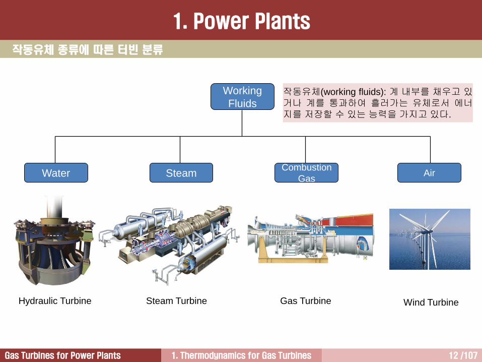
작동유체 종류에 따른 터빈 분류
작동유체(working fluids): 계 내부를 채우고 있거나 계를 통과하여 흘러가는 유체로서 에너지를 저장할 수 있는 능력을 가지고 있다.
Working
Fluids
Water SteamCombustion
Gas
Hydraulic Turbine Steam Turbine Gas Turbine
Air
Wind Turbine
1. Power Plants

1. Thermodynamics for Gas Turbines 13 /107Gas Turbines for Power Plants
A Typical Gas Turbine for Power
Generation
A Typical Steam Turbine for
Power Generation
Heat Engines
2. Change of State
발전설비의 효율 극대화를 위해 극단적인 열 및 유동 조건 적용
• Thermodynamics: the higher maximum cycle temperature and pressure, the greater specific power output and thermal efficiency (A-USC coal-fired power plants, & H-class GTs)
• Fluid dynamics: supersonic flow, stall, surge, choking, cooling
• Materials: heat resistant materials (creep), erosion, corrosion, coating
• Others: reliability/availability

1. Thermodynamics for Gas Turbines 14 /107Gas Turbines for Power Plants
Microscopic View (미시적 관점):
물질을 입자단위로 고찰Macroscopic View (거시적 관점):
물질을 연속체라고 가정
Microscopic View Macroscopic View
Mass unit Molecular Whole gas
Physical properties
Mass,
Momentum,
Energy
Density,
Temperature,
Pressure
2. Change of State
열역학적 관점
1. Thermodynamics for Gas Turbines 15 /107Gas Turbines for Power Plants
물질의 상(phase)은 공간 상에 어떤 물질들이 모여서 거시적 관점에서 균일한 물리적 성질, 예를 들어 균일한 밀도, 비열, 열전도도 등을 갖는 계를 지칭
미시적으로는 동일한 개체들로 구성된 계일지라도 거시계를 만들면 그것이 처한 상황에 따라 물리적 성질이크게 구별되는 다른 상으로 나타날 수 있는데, 물이 압력과 온도 값에 따라 기체, 액체, 고체 상태를 취하는경우가 대표적인 예. 얼음, 물, 증기의 경우 분자식은 H2O로 같지만 얼음의 경우 분자는 가깝게 모여있고, 액체인 물의 경우 조금 더 떨어져 있고, 증기의 경우에는 훨씬 더 떨어져 있음
특정 물질이 주어진 외부 조건에서 어떤 상을 취하는 지, 그리고 외부 조건이 변하면서 어떤 상변화가 가능한가에 대한 이해는 열역학에서 대단히 중요한 문제임
상변화 가운데 기체가 액체로 변하는 응축과 액체가 기체로 전이하는 증발은 가장 대표적인 상변화
어떤 계에서 나타나는 상변화는 대개의 경우 다른 열역학적 변수를 고정시켰을 때 특정 온도를 경계로 일어나는데, 이 온도를 해당 상변화의 임계온도(critical temperature)라 함
그리고 상변화 경계 양쪽에 위치한 두 상들은 일반적으로 다른 엔트로피 함수를 갖는데, 그것은 두 상 중 하나가 더 질서화된 상태에 해당하기 때문임. 예를 들면, 액체에서 고체로의 변화와 관련해서는 고체 상태에 있을 때 물질을 구성하는 분자들이 더 질서화되었다고 말할 수 있음
물이 얼음으로 변하는 경우와 물이 증기로 변하는 상변화가 일어나는 경우 온도가 일정하게 유지되는 것은잠열(latent heat)이 관계하기 때문
그러나 열에너지의 흐름은 있어도 온도 변화가 없는 경우 내부에너지는 변화
물질이 다르면 내부의 분자 배열이 다르기 때문에 상변화가 일어날 때 에너지 증감이 달라짐. 또한 에너지 증감은 물질의 양에 따라서도 달라짐
2. Change of State
상 (Phase) [1/2]

1. Thermodynamics for Gas Turbines 16 /107Gas Turbines for Power Plants
2. Change of State
상 (Phase) [2/2]
Critical temperature
Vapor
(steam)
Liquid
(water)
Solid
(ice)
Triple
point
l-s
l-v
s-v
0.0 0.01 100 374 T, C
0.006
1.0
218
p, atm
물질의 상에 관한 정보를 기술하는 편리한방법으로 상그림(phase diagram) 이용
물의 상변화는 온도(T)를 x좌표, 압력(p)을 y좌표로 설정한 그림으로 나타낼 수 있음.
이 상그림에서 곡선 l-v, s-v, l-s는 상 경계
곡선 l-v는 액체 상태의 물과 증기가 서로 평형을 이루는 점들, 즉 끓는점을 나타냄
곡선 l-s는 액체 상태와 고체 상태가 평형을이루는 점들, 즉 물의 어는점을 나타냄
곡선 s-v는 고체 상태에서 액체 상태를 거치지 않고 바로 증기 상태로의 변화, 즉 승화가가능한 점들을 나타냄
지금까지 언급한 세 곡선들은 한 점, 즉 온도가 0.01°C이고 압력이 0.006 기압인 점에서만나고 있는데, 이 점이 물의 삼중점(triple point)으로 세 가지의 상이 평형을 이루고 함께 존재할 수 있는 경우에 해당함
1. Thermodynamics for Gas Turbines 17 /107Gas Turbines for Power Plants
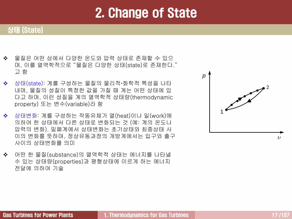
물질은 어떤 상에서 다양한 온도와 압력 상태로 존재할 수 있으며, 이를 열역학적으로 “물질은 다양한 상태(state)로 존재한다.”고 함
상태(state): 계를 구성하는 물질의 물리적화학적 특성을 나타내며, 물질의 성질이 특정한 값을 가질 때 계는 어떤 상태에 있다고 하며, 이런 성질을 계의 열역학적 상태량(thermodynamic property) 또는 변수(variable)라 함
상태변화: 계를 구성하는 작동유체가 열(heat)이나 일(work)에의하여 한 상태에서 다른 상태로 변화되는 것 (예: 계의 온도나압력의 변화). 밀폐계에서 상태변화는 초기상태와 최종상태 사이의 변화를 뜻하며, 정상유동과정의 개방계에서는 입구와 출구사이의 상태변화를 의미
어떤 한 물질(substance)의 열역학적 상태는 에너지를 나타낼수 있는 상태량(properties)과 평형상태에 이르게 하는 에너지전달에 의하여 기술
p
1
2
2. Change of State
상태 (State)
1. Thermodynamics for Gas Turbines 18 /107Gas Turbines for Power Plants
상태량: 물질의 성질을 나타내는 양
• 대표적 상태량: 온도, 압력, 체적, 질량, 밀도 등
• 추상적 상태량: 내부에너지, 엔트로피 등
• 열역학적 상태량은 점함수: 어떤 계에서 이들 열역학적 상태량은 그 상태에 도달한 경로와는 무관하며, 최종상태에 의해서만 결정됨
• 거시적 상태량: 물질이 다수의 분자로 이루어짐에 따라 이들 양의 조합에 의해 물질의 상태를 나타낼 수있을 때 이들 양을 거시적 상태량이라 함 (밀도, 온도, 압력 등)
• 미시적 상태량: 분자 수준의 상태로 나타낼 수 있는 양 (질량, 운동량, 에너지 등)
강도성 상태량 vs. 종량성 상태량: 물질의 성질을 나타내는 양
• 대표적 상태량: 온도, 압력, 체적, 질량, 밀도 등
2. Change of State
상태량 (Thermodynamic Properties) [1/2]

1. Thermodynamics for Gas Turbines 19 /107Gas Turbines for Power Plants
2. Change of State
상태량 (Thermodynamic Properties) [1/2]
+
m
V
T
p
m/2
V/2
T
p
m/2
V/2
T
p
Extensive properties
Intensive properties
Intensive Properties Extensive Properties
• 물질의 질량과 관계 없으며, 계 내부의 임의의한 지점에서 규정될 수 있음
• 압력, 온도, 밀도
• 비체적, 비엔탈피, 비엔트로피, 비내부에너지
• 열역학에서 주로 사용하며, 소문자로 표시
• 물질의 질량에 정비례하여 변함
• 질량, 체적, 엔탈피, 엔트로피, 내부에너지
• 대문자로 표시
비체적(specific volume): 단위질량당 체적 (종량성 상태량인 체적을 강도성 상태량으로 나타내기 위함)
= V /m [m3/kg]
밀도(density): 단위체적당 질량
= m /V [kg/m3] ( = 1 / )

1. Thermodynamics for Gas Turbines 20 /107Gas Turbines for Power Plants
과정(process): 계를 구성하는 물질이 한 상태에서 다른 상태로 변화할 때 상태가 변해가는 연속된 경로
과정 종류: 정압과정, 정적과정, 등온과정, 단열과정, 등엔트로피과정, 폴리트로픽과정
사이클(cycle): 어떤 물질의 상태가 일련의 과정을 거친 후 다시 최초상태로 돌아왔을 때 계는 사이클을 이루었다고 함. 따라서 사이클이 완료되면 계의 열역학적 상태량은 계가 최초에 가졌던 상태량과 동일해짐
가역과정(reversible process):
• 어떤 진행된 과정을 거꾸로 진행시켰을 경우 계 및 주위가 최초 상태로 되돌려질 수 있는 과정
• 마찰손실을 수반하지 않는 과정
• 유체마찰과 열전달이 없는 경우 가역과정이 가능하지만 유체가 흘러가는 동안 마찰과 열전달이 필수적으로 수반되기 때문에 가역과정은 실질적으로 불가능
• 열역학에서 이론적으로 취급하는 모든 과정은 가역과정으로 가정. 이는 각종 열기관에서 실제로 발생하는 유체마찰에 의한 손실과 열전달 손실을 이론적으로 반영하기 어렵기 때문임
비가역과정(irreversible process): 과정이 진행되는 동안 마찰손실을 수반하는 과정
p
1 2
[ 정압과정 ] [ 정적과정 ] [ 등온과정 ] [ 단열과정 ]
T 1 2
s
T
1
2
s
p
1
2
2. Change of State
과정 (Process)

1. Thermodynamics for Gas Turbines 21 /107Gas Turbines for Power Plants
3. The First Law of Thermodynamics
열역학은 일(work)과 열(heat)을 다루는 과학
• 일: 어떤 물체를 힘을 가해서 이동시켰을 때, 물체가 이동한 방향으로 작용한 힘의 크기와 변위의 곱
• 열: 온도차가 존재하는 경우에 계의 경계를 넘어서 이동하는 에너지
• 일과 열은 열역학적 상태량이 아니라 물질의 에너지 상태 및 열역학적 상태량을 달라지게 하는 열역학적인 양(thermodynamic quantities)으로서 일과 열은 에너지 전달임
일은 쉽게 열로 변환 가능
열은 일과 동등한 에너지이지만 열을 일로 변환시키기 위해서는 힘이 필요한데 열 속에는 힘에 대한 요소가없음. 따라서 열을 직접적으로 일로 바꿀 수는 없으며, 반드시 열기관을 필요로 함
열기관: 열의 일부를 일(동력)이나 역학적 에너지로 변환시키는 장치
열기관은 공기나 증기와 같은 물질의 압력 및 온도가 쉽게 변하는 성질을 이용하여 열을 일로 변환
열기관에 사용하는 공기나 증기와 같은 물질을 작동유체(working fluid)라 함
작동유체 정의: 계 내부를 채우고 있거나 계를 통과하여 흘러가는 유체로서 열에너지를 저장(보관)할 수 있는능력을 가지고 있음. 작동유체의 열역학적 상태변화를 통해서 확인 가능
따라서 열기관 이해를 위해서 작동유체의 상태변화에 대한 이해가 매우 중요 equations of state
• 대표적인 상태방정식: 이상기체 상태방정식
열기관에서 작동유체의 상태변화는 정압, 정적, 단열, 등온과정과 같은 여러 가지 과정(process)으로 나타남
대표적인 열역학적 상태량: 온도, 압력, 비체적, 내부에너지, 엔탈피, 엔트로피 등
RTp
일반사항 [1/2]

1. Thermodynamics for Gas Turbines 22 /107Gas Turbines for Power Plants
3. The First Law of Thermodynamics
일반사항 [2/2]
열역학 제1법칙 = 에너지 보존법칙
• 흔히 열량이라고도 불리는 열은 에너지의 한 형태로서 열은 일로 변할 수 있고 일 또한 열로 변할 수 있으며, 이런 변화가 아무리 진행되더라도 에너지 총량은 변하지 않고 항상 일정하게 유지
• 이를 열역학적으로 표현하면, “어떤 주어진 시간에 계 내부로 들어간 에너지는 그 계로부터 빠져나간 에너지와 그 계 내부에 저장된 에너지를 합친 것과 동일하다.”
작동유체에 포함되어 있는 열에너지는 열기관에 동력을 발생시킬 수 있는 다양한 에너지 형태로 변환됨
따라서 각종 열기관을 이해하는 데 있어서 가장 중요한 것은 열기관 각각의 구성품에서 일어나는 다양한 에너지 변환과 열과 일의 전달 및 변환임
이에 대한 내용을 이해하면 열기관 주요 구성품의 운전원리, 설계방법, 출력, 효율 등과 같은 가장 핵심적인사항을 살펴볼 수 있음
가장 대표적인 열기관인 발전설비는 일차적으로 연소기 또는 보일러에서 연료를 연소시켜 연료가 가지고 있는 화학적 에너지를 열에너지로 변환시킨 후 열에너지를 작동유체에 전달하여 작동유체의 에너지 수준을 높여서 터빈으로 전달.
터빈은 전달받은 열에너지를 기계적 에너지로 변환시켜 발전기로 전달. 발전기는 전달받은 기계적 에너지를이용하여 전기에너지로 변환. 이런 점에서 발전설비는 단순하게 에너지 변환장치라고 할 수 있음
따라서 발전설비를 이해하기 위해서는 화학적 에너지로부터 출발하여 전기에너지가 만들어지기까지 다양하게 이루어지는 에너지 전달 및 변환과정에 대한 내용을 자세하게 파악해야 함
1. Thermodynamics for Gas Turbines 23 /107Gas Turbines for Power Plants
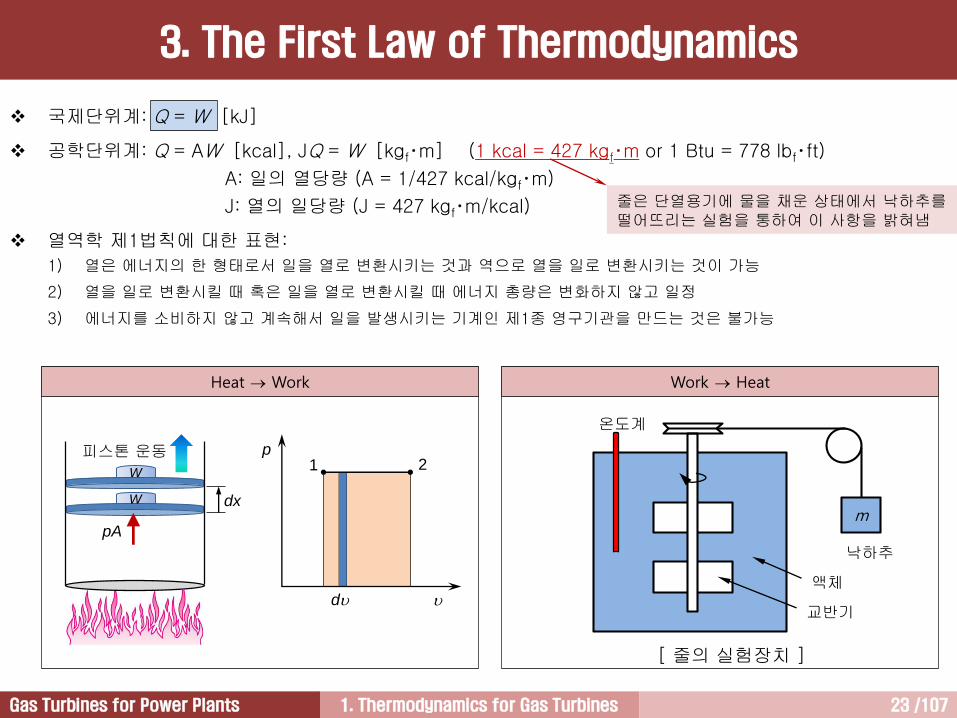
국제단위계: Q = W [kJ]
공학단위계: Q = AW [kcal], JQ = W [kgf‧m] (1 kcal = 427 kgf‧m or 1 Btu = 778 lbf‧ft)
A: 일의 열당량 (A = 1/427 kcal/kgf‧m)
J: 열의 일당량 (J = 427 kgf‧m/kcal)
열역학 제1법칙에 대한 표현:
1) 열은 에너지의 한 형태로서 일을 열로 변환시키는 것과 역으로 열을 일로 변환시키는 것이 가능
2) 열을 일로 변환시킬 때 혹은 일을 열로 변환시킬 때 에너지 총량은 변화하지 않고 일정
3) 에너지를 소비하지 않고 계속해서 일을 발생시키는 기계인 제1종 영구기관을 만드는 것은 불가능
m
온도계
낙하추
교반기
액체
[ 줄의 실험장치 ]
pA
피스톤 운동
dx
W
W
p
d
1 2
Heat Work Work Heat
줄은 단열용기에 물을 채운 상태에서 낙하추를떨어뜨리는 실험을 통하여 이 사항을 밝혀냄
3. The First Law of Thermodynamics

1. Thermodynamics for Gas Turbines 24 /107Gas Turbines for Power Plants
Bucket
Internal Energy [1/2]
3. The First Law of Thermodynamics

1. Thermodynamics for Gas Turbines 25 /107Gas Turbines for Power Plants
p
1
2
강체의 밀폐용기 가열 (정적가열) 강체의 밀폐용기를 가열하여도 생산된 일 없음
그러나 열은 계 내부로 전달되었음. 그러므로 열역학 제1법칙인 Q = W가 성립하지 않음
이를 보완하기 위해 내부에너지에 대한 정의가 필요
내부에너지: 분자운동 형태로 계 내부에 저장되어 있는에너지
비록 직접적으로 측정하기는 어렵지만 각각의 분자들은에너지를 가짐
그리고 이들 분자들은 직진, 진동, 회전 등과 같은 불규칙한 운동(random motions)을 하는데, 이에 관련된 에너지를 운동에너지와 위치에너지 같이 체계적인 형태로 나타내기 어려움
따라서 이런 무질서한 형태로 저장되어 있는 에너지를 열역학적인 상태량인 내부에너지라 함. 즉 내부에너지는 물체가 가지는 총 에너지 가운데 역학적 에너지(운동에너지와 위치에너지)와 전기 및 자기에너지 등 외계와의 관계에 의해 좌우되는 외적인 에너지를 제외한 물체 자신이 가지고 있는 내적인 에너지를 말함
따라서 열역학 제1법칙은 다음과 같이 변형됨
내부에너지를 측정하기는 쉽지 않음. 그런데 일반적으로 온도는 내부에너지의 크기에 비례하여 증가하기 때문에 온도를 이용하면 내부에너지 크기를 계산할 수 있음
그러나 온도측정을 통해 항상 내부에너지의 크기를 알 수 있는 것은 아닌데, 이는 작동유체가 물인 경우 내부에너지 일종인 증발열이나 융해열과 같은 잠열은 온도에 비례하지 않는 성질을 가지기 때문
wuq WQ
3. The First Law of Thermodynamics
Internal Energy [2/2]

1. Thermodynamics for Gas Turbines 26 /107Gas Turbines for Power Plants
c1
c2q
wz1
z2
1
2
Open System
식 는 밀폐계에 대한 열역학 제1법칙
이제 개방계 열기관에 적용할 수 있는 열역학 제1법칙을 유도
그림에서 계 내부로 열량을 공급하고 있으며, 계에서 일이 생산되고 있는데, 이는 발전설비를 포함한 모든 열기관의 공통적인 특징
경험적 사실을 바탕으로 작동유체가 출입하는 개방계를 살펴보면, 에너지에는 내부에너지, 유동에너지(flow energy), 운동에너지, 위치에너지가 있음
물론 여기에는 추가적으로 표면장력, 자기력, 전기력 등에 의한 에너지가 있을 수 있지만 이들 에너지는 발전용 가스터빈과 같은 개방계 열기관뿐만 아니라 피스톤 왕복엔진과 같은 밀폐계 열기관에에도 큰 영향을 미치지 못하는데, 이는 이런 에너지들이 각종 열기관을 통과하는 작동유체에 큰 영향을 미치지 못하기 때문
따라서 개방계 열기관에 작용하는 에너지는 다음과같음
그리고 개방계에 적용할 수 있는 열역학 제1법칙은다음과 같이 일반화 가능
위 식을 미분형으로 나타내면,
따라서 개방계 열역학 제1법칙은
PEKEFEue
dwdedq
dwPEdKEdFEddudq )()()(
wuq
weq wuq
개방계에서 작동유체의 에너지 변화
3. The First Law of Thermodynamics
1. Thermodynamics for Gas Turbines 27 /107Gas Turbines for Power Plants
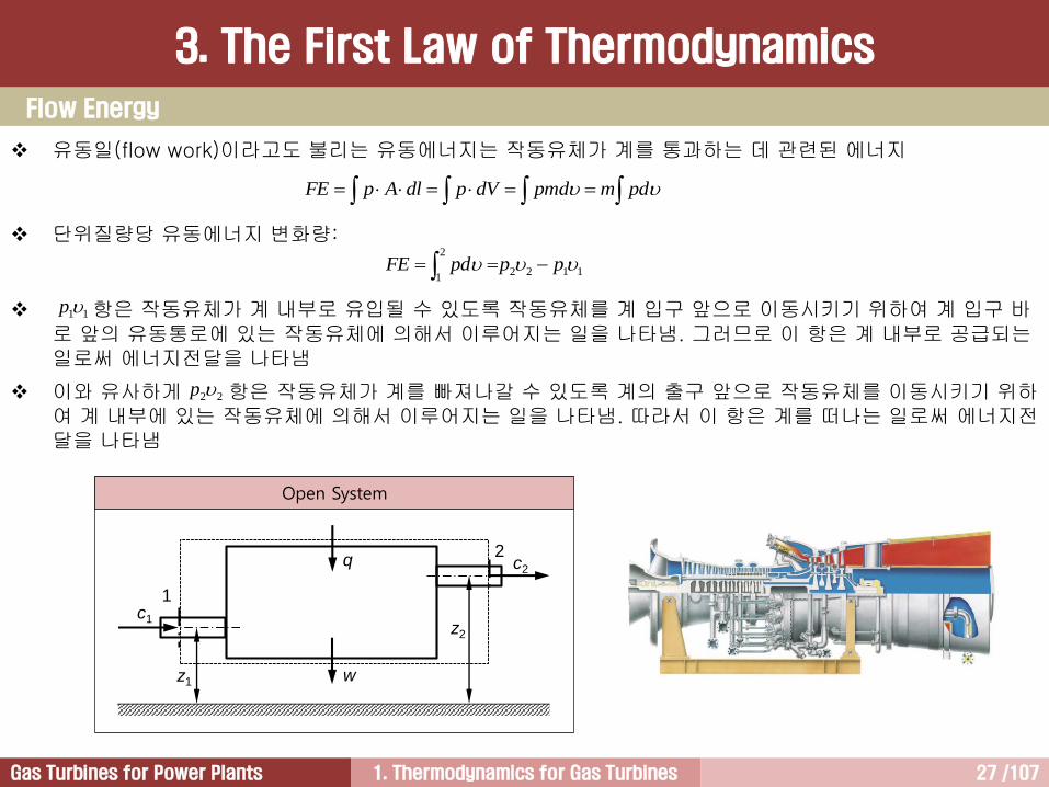
pdmpmddVpdlApFE
유동일(flow work)이라고도 불리는 유동에너지는 작동유체가 계를 통과하는 데 관련된 에너지
단위질량당 유동에너지 변화량:
항은 작동유체가 계 내부로 유입될 수 있도록 작동유체를 계 입구 앞으로 이동시키기 위하여 계 입구 바로 앞의 유동통로에 있는 작동유체에 의해서 이루어지는 일을 나타냄. 그러므로 이 항은 계 내부로 공급되는일로써 에너지전달을 나타냄
이와 유사하게 항은 작동유체가 계를 빠져나갈 수 있도록 계의 출구 앞으로 작동유체를 이동시키기 위하여 계 내부에 있는 작동유체에 의해서 이루어지는 일을 나타냄. 따라서 이 항은 계를 떠나는 일로써 에너지전달을 나타냄
1122
2
1 pppdFE
11p
22p
c1
c2q
wz1
z2
1
2
Open System
Flow Energy
3. The First Law of Thermodynamics
1. Thermodynamics for Gas Turbines 28 /107Gas Turbines for Power Plants
Absolute Work
pA
피스톤 운동
dx
W
W
p
d
1 2
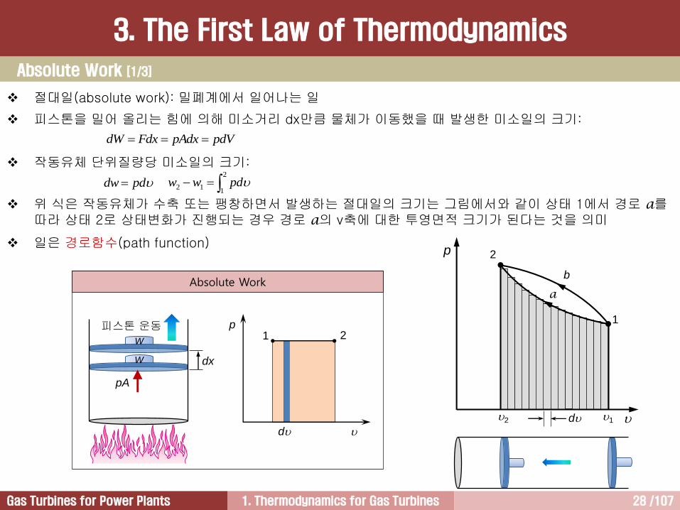
절대일(absolute work): 밀폐계에서 일어나는 일
피스톤을 밀어 올리는 힘에 의해 미소거리 dx만큼 물체가 이동했을 때 발생한 미소일의 크기:
작동유체 단위질량당 미소일의 크기:
위 식은 작동유체가 수축 또는 팽창하면서 발생하는 절대일의 크기는 그림에서와 같이 상태 1에서 경로 a를따라 상태 2로 상태변화가 진행되는 경우 경로 a의 v축에 대한 투영면적 크기가 된다는 것을 의미
일은 경로함수(path function)
pdVpAdxFdxdW
pddw 2
112 pdww
p 2
1
12
b
a
d
Absolute Work [1/3]
3. The First Law of Thermodynamics
1. Thermodynamics for Gas Turbines 29 /107Gas Turbines for Power Plants
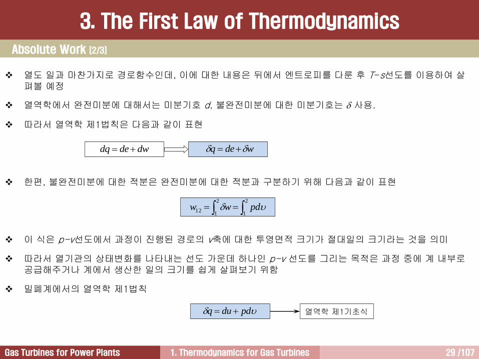
열도 일과 마찬가지로 경로함수인데, 이에 대한 내용은 뒤에서 엔트로피를 다룬 후 T-s선도를 이용하여 살펴볼 예정
열역학에서 완전미분에 대해서는 미분기호 d, 불완전미분에 대한 미분기호는 사용.
따라서 열역학 제1법칙은 다음과 같이 표현
한편, 불완전미분에 대한 적분은 완전미분에 대한 적분과 구분하기 위해 다음과 같이 표현
이 식은 p-v선도에서 과정이 진행된 경로의 v축에 대한 투영면적 크기가 절대일의 크기라는 것을 의미
따라서 열기관의 상태변화를 나타내는 선도 가운데 하나인 p-v 선도를 그리는 목적은 과정 중에 계 내부로공급해주거나 계에서 생산한 일의 크기를 쉽게 살펴보기 위함
밀폐계에서의 열역학 제1법칙
2
1
2
112 pdww
pdduq 열역학 제1기초식
wdeq dwdedq
Absolute Work [2/3]
3. The First Law of Thermodynamics
1. Thermodynamics for Gas Turbines 30 /107Gas Turbines for Power Plants
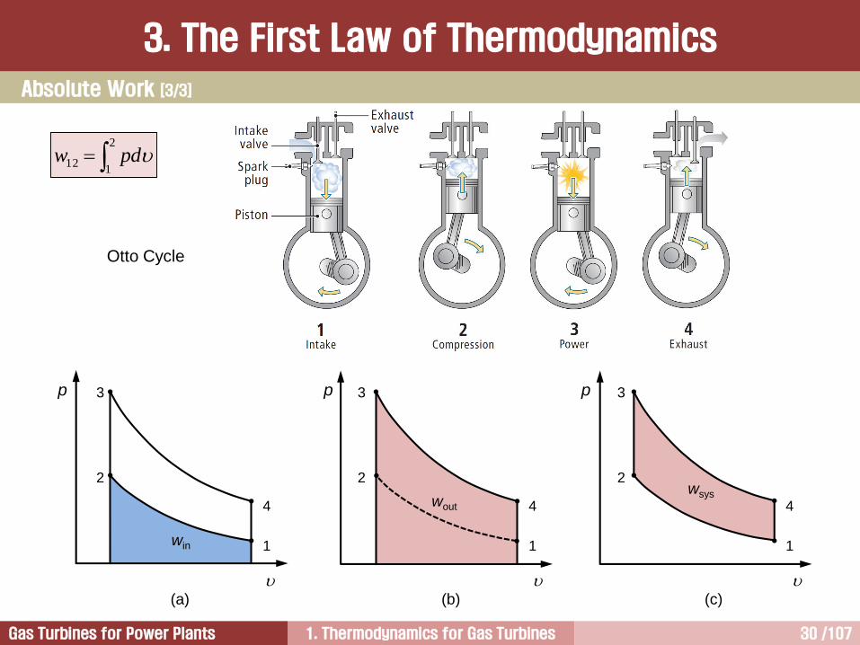
Otto Cycle
p
win
2
1
3
4
(a)
2
3p
wout
1
4
(b)
p
2
1
3
4
wsys
(c)
2
112 pdw
Absolute Work [3/3]
3. The First Law of Thermodynamics

1. Thermodynamics for Gas Turbines 31 /107Gas Turbines for Power Plants
열역학적 상태량은 상태변화가 일어난 경로(path)에 좌우되어 그변화량이 결정되는 상태량이 있는 반면에 경로에는 무관하게 최초상태와 최종상태에 의해서만 상태변화량이 결정되는 상태량이 있다.
예를 들면, 열과 일은 상태변화가 일어난 경로에 따라 상태변화량크기가 달라지는 경로함수(path function)이며, 상태변화량은 수학적으로 불완전미분을 이용해서 구해진다.
이에 반해서 내부에너지의 상태변화량 크기는 상태변화가 일어난경로에 무관하고 최초상태와 최종상태에 의해서만 상태변화량이결정되는 점함수(point function)이며, 상태변화량은 수학적으로 완전미분을 이용해서 구해진다.
열역학에서 완전미분에 대해서는 미분기호 d , 불완전미분에 대한미분기호는 를 사용한다.
완전미분과 불완전미분을 통해서 구해진 상태변화량 크기를 서로구분하기 위하여 각각 다음과 같이 표현한다.
2
112ww
2
112 hhdh
p 2
1
12
b
a
d
Point Function vs. Path Function
3. The First Law of Thermodynamics

1. Thermodynamics for Gas Turbines 32 /107Gas Turbines for Power Plants
과정 11:
• 흡입과정
• 일의 크기 = 면적 1-1-1-0-1
과정 12:
• 팽창과정
• 일의 크기 = 면적 1-2-2-1-1
과정 22:
• 배기과정
• 일의 크기= -(면적 2-2-0-2-2)
과정 21:
• 공급압력 상승
• 일의 크기= 0
유동가스가 한 공업일의 크기 = 면적 1-1-2-2-1
공업일 역시 경로함수
2
112 dpw
p
2
1
dp
1
2
0
21
p1
p2
1 2
Technical Work [1/2]
3. The First Law of Thermodynamics
1. Thermodynamics for Gas Turbines 33 /107Gas Turbines for Power Plants
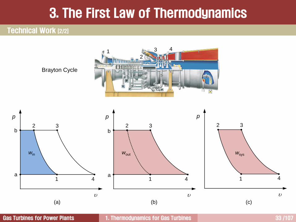
Brayton Cycle
12
3 4
p
2
1
3
4
win
(a)
p
2
1
3
4
wout
(b)
p
2
1
3
4
wsys
(c)
b
a
b
a
Technical Work [2/2]
3. The First Law of Thermodynamics

1. Thermodynamics for Gas Turbines 34 /107Gas Turbines for Power Plants
밀폐계에서의 일 개방계에서의 일
2
112 dpw
2
112 pdw
p 2
1
12 d
p
2
1
p2
dp
p1
Absolute Work Technical Work
일의 종류
3. The First Law of Thermodynamics

1. Thermodynamics for Gas Turbines 35 /107Gas Turbines for Power Plants
p
2
1
12
p1
p2
w12
p
2
1
1 2
p2
p1
w12
02
112 pdw0
2
112 pdw
[ 계가 압축될 때의 p-선도 ] [ 계가 팽창될 때의 p-선도 ]
pA 피스톤운동
pA 피스톤운동
For a simple compressible substance,
defined to be one for which the only
relevant work is compression or
expansion, reversible work is given by
This equation shows that when a fluid
is compressed so that its volume
decreases, work is negative, meaning
that work is done on the system.
On the contrary, when a fluid is
expanded so that its volume increases,
work is positive, meaning that work is
delivered from the system.
2
112 pdw
열역학 제1법칙 = 에너지 보존법칙
• 열은 에너지로서 일로 변할 수 있고 일 또한 열로 변할 수 있으며, 이런 변화가 아무리 진행되더라도 에너지 총량은 변하지 않고 항상 일정하게 유지
• 어떤 주어진 시간에 계 내부로 들어간 에너지는 그 계로부터 빠져나간 에너지와 그 계 내부에 저장된 에너지를 합친 것과 동일
일의 방향성과 작동유체의 에너지 수준 변화 [1/4]
3. The First Law of Thermodynamics

1. Thermodynamics for Gas Turbines 36 /107Gas Turbines for Power Plants
일의 방향성과 작동유체의 에너지 수준 변화 [2/4]
3. The First Law of Thermodynamics
1. Thermodynamics for Gas Turbines 37 /107Gas Turbines for Power Plants
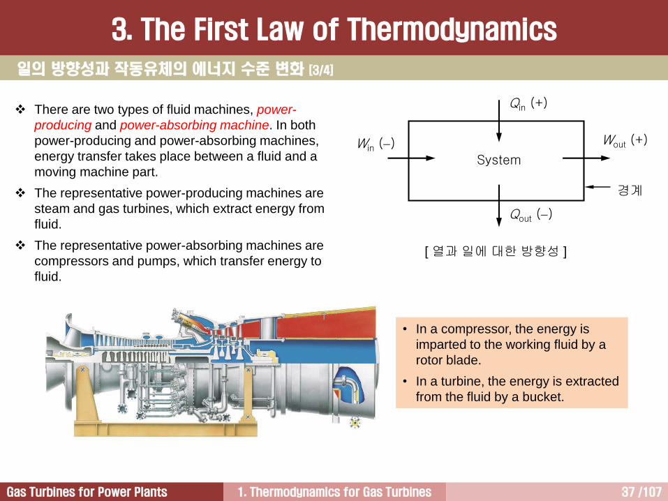
[ 열과 일에 대한 방향성 ]
System
Win () Wout (+)
Qout ()
Qin (+)
경계
There are two types of fluid machines, power-
producing and power-absorbing machine. In both
power-producing and power-absorbing machines,
energy transfer takes place between a fluid and a
moving machine part.
The representative power-producing machines are
steam and gas turbines, which extract energy from
fluid.
The representative power-absorbing machines are
compressors and pumps, which transfer energy to
fluid.
• In a compressor, the energy is
imparted to the working fluid by a
rotor blade.
• In a turbine, the energy is extracted
from the fluid by a bucket.
일의 방향성과 작동유체의 에너지 수준 변화 [3/4]
3. The First Law of Thermodynamics
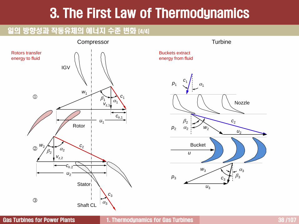
1. Thermodynamics for Gas Turbines 38 /107Gas Turbines for Power Plants
c1
w1
c,1
11
vz,1
u1
w2 c2
c,2
22
vz,2
u2
c3
Shaft CL
IGV
Rotor
Stator
3
Compressor Turbine
Rotors transfer
energy to fluid
Buckets extract
energy from fluid
u2
u3
c2
w2
2
2
w3
3c3
p1
p2
p3
u
1
c1
3
Nozzle
Bucket
일의 방향성과 작동유체의 에너지 수준 변화 [4/4]
3. The First Law of Thermodynamics

1. Thermodynamics for Gas Turbines 39 /107Gas Turbines for Power Plants
Heat
3. The First Law of Thermodynamics
열은 열역학적으로 평형에 도달하는 과정에서 고온체로부터 저온체로 흘러가며, 열평형에 도달한 후에 열은 더이상 전달되지 않음.
즉 열(heat)은 계와 주위 또는 다른 계와의 온도차에 의하여 이동하는 에너지로서 Q로 표시.
열에 의한 에너지 전달은 다음 식으로 표현.
(or )
비열(c)은 어떤 단위질량을 가지는 물질의 온도를 1℃ 상승시키는 데 필요한 열량을 의미.
TmcQ mcdTQ
한편, 단위질량당 전달된 열량을 나타내기 위하여 소문자 ‘q' 사용.
열역학적 계에서 전달된 열이 없는 경우 단열(adiabatic)이라 함.
열은 부호를 가지며, 계로 유입되는 열을 양(+)의 열, 계를 빠져나가는 열을 음(-)의 열이라 함.
T1(Hot)
T2(Cold)
mcdTQ
QHeat
mcdTQ cdTq
단열과정 0q
SystemWin () Wout (+)
Qout ()
Qin (+)
경계
1 kcal = 물 1 kg의 온도를 1℃ (14.5℃15.5℃)상승시키는데필요한 열량
1 Btu = 물 1 lbm의 온도를 1℉(63℉ 64℉) 상승시키는데 필요한 열량 (1 Btu = 0.252 kcal)
1. Thermodynamics for Gas Turbines 40 /107Gas Turbines for Power Plants
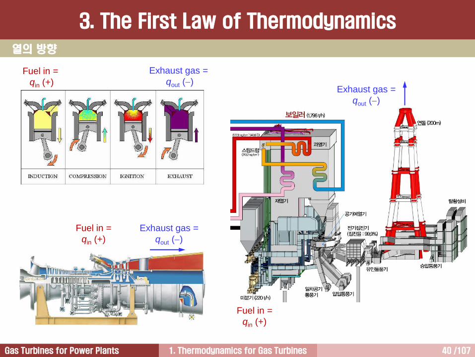
열의 방향
Fuel in =
qin (+)
Fuel in =
qin (+)
Exhaust gas =
qout ()
Exhaust gas =
qout ()
Exhaust gas =
qout ()
Fuel in =
qin (+)
3. The First Law of Thermodynamics
1. Thermodynamics for Gas Turbines 41 /107Gas Turbines for Power Plants
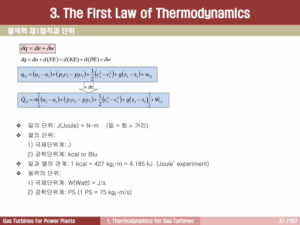
열역학 제1법칙과 단위
3. The First Law of Thermodynamics
일의 단위: J(Joule) = N‧m (일 = 힘 거리)
열의 단위:
1) 국제단위계: J
2) 공학단위계: kcal or Btu
일과 열의 관계: 1 kcal = 427 kgf‧m = 4.185 kJ (Joule’ experiment)
동력의 단위:
1) 국제단위계: W(Watt) = J/s
2) 공학단위계: PS (1 PS = 75 kgf‧m/s)
wdeq
1212
2
1
2
2112212122
1wzzgccppuuq
1212
2
1
2
2112212122
1WzzgccppuumQ
wPEdKEdFEdduq )()()(
m

1. Thermodynamics for Gas Turbines 42 /107Gas Turbines for Power Plants
pA
피스톤운동
dx
W
W
[ 정압가열]
[Exercise]
1) 발전설비에서 정압가열이 중요한 이유를 설명하시오.
2) 발전설비 성능과 관련하여 중요하게 취급되는 열역학적 상태량은 무엇인가?
wduq 밀폐계에 대한 열역학 제1법칙:
밀폐계 정압가열과정에 대한 일의 크기는,
따라서 다음과 같은 관계식 성립
• 밀폐계 정압과정에서 가열한 열량의 크기는 (u + p) 상태량
변화에 이용
• p는 유동에너지(또는 유동일)라 함
• 엔탈피는 내부에너지와 유동에너지의 합
2
1112212 pppdww
11122212 pupuq
puh 1212 hhq
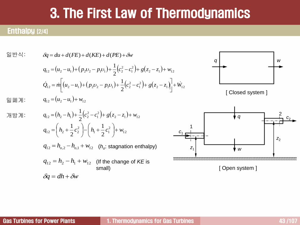
Enthalpy [1/4]
3. The First Law of Thermodynamics
1. Thermodynamics for Gas Turbines 43 /107Gas Turbines for Power Plants
c1
c2q
wz1
z2
1
2
q w
[ Closed system ]
[ Open system ]
1212
2
1
2
2112212122
1wzzgccppuuq
1212
2
1
2
212122
1wzzgcchhq
일반식:
밀폐계:
개방계:
121212 wuuq
1212
2
1
2
2112212122
1WzzgccppuumQ
wPEdKEdFEdduq )()()(
12
2
11
2
22122
1
2
1wchchq
121212 whhq
wdhq
121,2,12 whhq oo (ho: stagnation enthalpy)
(If the change of KE is
small)
Enthalpy [2/4]
3. The First Law of Thermodynamics
1. Thermodynamics for Gas Turbines 44 /107Gas Turbines for Power Plants
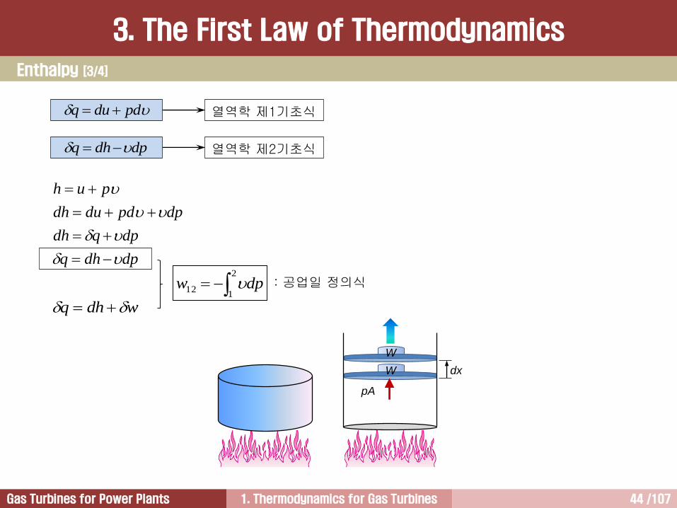
dpdhq
dpqdh
dppddudh
puh
pA
dx
W
W
wdhq
2
112 dpw : 공업일 정의식
dpdhq 열역학 제2기초식
열역학 제1기초식 pdduq
Enthalpy [3/4]
3. The First Law of Thermodynamics

1. Thermodynamics for Gas Turbines 45 /107Gas Turbines for Power Plants
2
111,2
1chho
R S
ho
h
[ A Compressor Stage ]
N B
ho
h
[ A Turbine Stage ]po and To variations are similar to ho,
p and T variations are similar to h
In a turbine stage, static enthalpy and pressure
drop occurs through the nozzles, which guide
the flow smoothly into a bucket.
All of the stagnation enthalpy and pressure drop
through the bucket.
In contrast, all of the stagnation enthalpy and
pressure rise through the rotor in a compressor
stage.
Blade
Direction Turbine
Blades
Compressor
Blades
c1w1
u
w2 c2
u
u
c2w2
u
w3 c3
Axial
Direction
Blade
Direction
Axial
Direction
Compressor Turbine
Enthalpy [4/4]
3. The First Law of Thermodynamics

1. Thermodynamics for Gas Turbines 46 /107Gas Turbines for Power Plants
Cycle: 계를 구성하는 작동유체가 일련의 과정을 거쳐서 최초의 상태로 다시 돌아왔을 경우 사이클(cycle)을 이루었다고 함. 따라서 사이클이 완료되면 작동유체의 열역학적 상태량은 최초의 상태량과 동일해짐.
Brayton Cycle - Open System Otto Cycle - Closed System
흡입 압축 연소 배기
p
2
1
3
4
2
1
3
4
p
Cycle
3. The First Law of Thermodynamics

1. Thermodynamics for Gas Turbines 47 /107Gas Turbines for Power Plants
Cycle Integration
3. The First Law of Thermodynamics
열역학 제1법칙은 사이클을 겪는 계에 대해서도 성립
wdeq
[ Otto Cycle ] [ Sabathe Cycle ]
2
1
3
4
p
1
5
2
3 4
p 0de wq
T
s
1
2
3
4
[ Otto Cycle ]
2
1
3
2
4
3
1
4qqqqqqsystem
41342312 qqqq
2
1
3
2
4
3
1
4wwwwwwsystem
41342312 wwww
Power output &
Thermal efficiency
Cycle Analysis
2
1
3
2
4
3
1
4dededededeesystem
041342312 eeeeeeee

1. Thermodynamics for Gas Turbines 48 /107Gas Turbines for Power Plants
1212
2
1
2
2112212122
1wzzgccppuuq
작동유체가 액체이면 엔탈피 측정이 어렵기 때문에 열역학 제1법칙은 다음과 같이 된다.
1212
2
1
2
2
1
1
2
21212
2
1wzzgcc
ppuuq
2
2
1cppo
여기서 p0는 정체압력(stagnation pressure)이다. 그러므로, 열역학 제1법칙은 다음과 같이 된다.
1212
1
1,
2
2,
1212 wzzgpp
uuqoo
한편, 작동유체가 액체인 경우 전체압력(total pressure)은 정체압력과 높이수두(elevation head)의 합으
로 정의된다.
gzpp ot
작동유체가 액체인 경우 열역학 제1법칙
3. The First Law of Thermodynamics
1. Thermodynamics for Gas Turbines 49 /107Gas Turbines for Power Plants
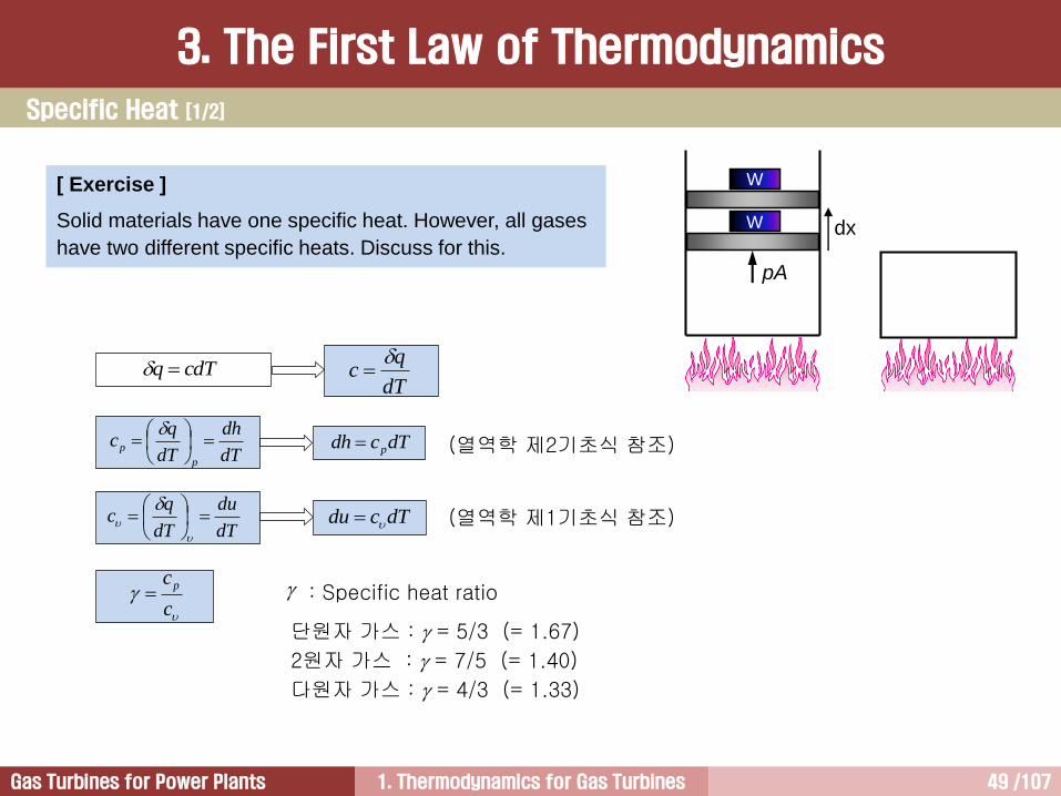
cdTq dT
qc
(열역학 제2기초식 참조)
(열역학 제1기초식 참조)
c
cp : Specific heat ratio
단원자 가스 : = 5/3 (= 1.67)
2원자 가스 : = 7/5 (= 1.40)
다원자 가스 : = 4/3 (= 1.33)
[ Exercise ]
Solid materials have one specific heat. However, all gases
have two different specific heats. Discuss for this.
W
pA
dx
W
dT
dh
dT
qc
p
p
dT
du
dT
qc
dTcdh p
dTcdu
Specific Heat [1/2]
3. The First Law of Thermodynamics

1. Thermodynamics for Gas Turbines 50 /107Gas Turbines for Power Plants
물: 지구상에 존재하는 물질 가운데 비열이 가장 크다.
물이 풍부한 지방이 온화; 겨울 동안 공기(cp=1004.7 J/kg-K)온도가 내려감에 따라 물에서 공기로 열이 전달되기 때문에 공기 온도 증가. 미국 서해안에는 겨울 동안에 동풍이 불기 때문에 동쪽의 육지로 따뜻한 공기가 유입. 따라서 미국의 경우 겨울엔 기후가 온화한 서해안 선호.
Substance J/kgK kcal/kgK
Aluminium 900 0.215
Beryllium 1,820 0.436
Cadmium 230 0.055
Copper 387 0.0924
Germanium 322 0.077
Gold 129 0.0308
Iron 448 0.107
Lead 128 0.0305
Silicon 703 0.168
Silver 234 0.056
Glass 837 0.20
Ice (-5C) 2,090 0.50
Wood 1,700 0.41
Alcohol (ethyl) 2,400 0.58
Mercury 140 0.033
Water (15C) 4,186 1.00
Steam (100C) 2,010 0.48
Specific Heats of Some Substances at 25C and
Atmospheric Pressure
해변에서 공기의 순환
한여름 더운 낮에 모래 위의 차가운 공기는 물 위에 있는 공기보다 더 빨리 가열. 따뜻해진 공기가 부력에 의해 상승하면 물위의 차가운 공기가 모래사장 쪽으로 유입.
Specific Heat [2/3]
3. The First Law of Thermodynamics
1. Thermodynamics for Gas Turbines 51 /107Gas Turbines for Power Plants
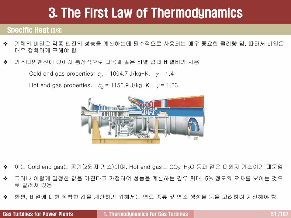
기체의 비열은 각종 엔진의 성능을 계산하는데 필수적으로 사용되는 매우 중요한 물리량 임. 따라서 비열은매우 정확하게 구해야 함
가스터빈엔진에 있어서 통상적으로 다음과 같은 비열 값과 비열비가 사용
Cold end gas properties: cp = 1004.7 J/kg-K, = 1.4
Hot end gas properties: cp = 1156.9 J/kg-K, = 1.33
이는 Cold end gas는 공기(2원자 가스)이며, Hot end gas는 CO2, H2O 등과 같은 다원자 가스이기 때문임
그러나 이렇게 일정한 값을 가진다고 가정하여 성능을 계산하는 경우 최대 5% 정도의 오차를 보이는 것으로 알려져 있음
한편, 비열에 대한 정확한 값을 계산하기 위해서는 연료 종류 및 연소 생성물 등을 고려하여 계산해야 함
Specific Heat [3/3]
3. The First Law of Thermodynamics
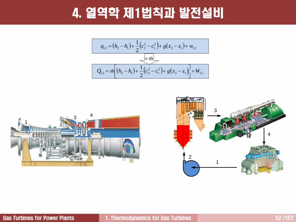
1. Thermodynamics for Gas Turbines 52 /107Gas Turbines for Power Plants
3
4
21
12
34
1212
2
1
2
212122
1wzzgcchhq
1212
2
1
2
212122
1WzzgcchhmQ
m
4. 열역학 제1법칙과 발전설비
1. Thermodynamics for Gas Turbines 53 /107Gas Turbines for Power Plants
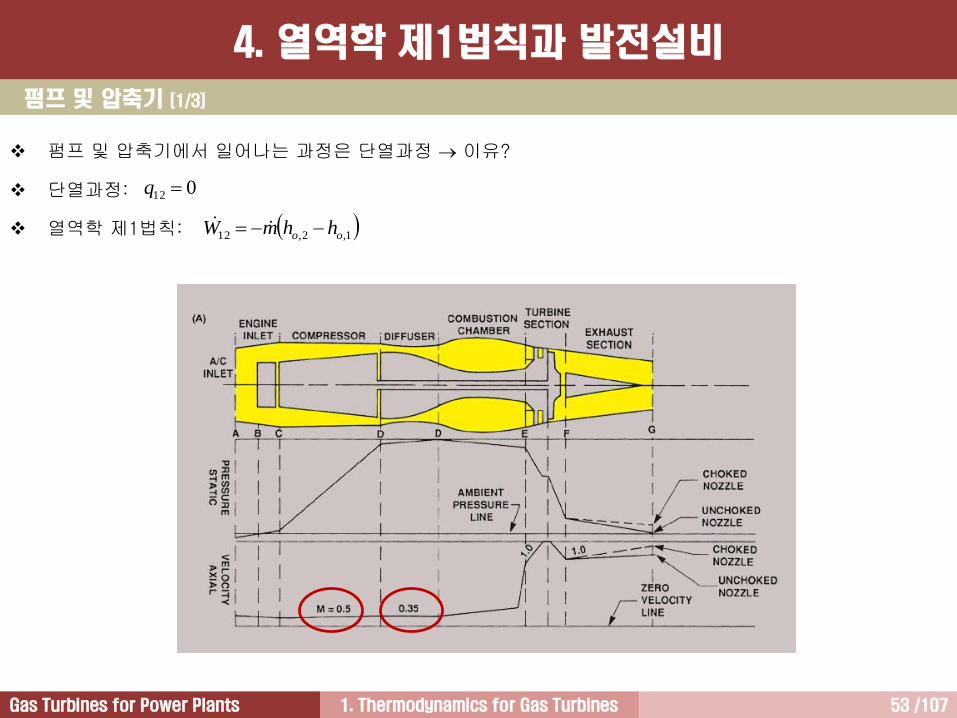
펌프 및 압축기 [1/3]
펌프 및 압축기에서 일어나는 과정은 단열과정 이유?
단열과정:
열역학 제1법칙:
012 q
1,2,12 oo hhmW
4. 열역학 제1법칙과 발전설비

1. Thermodynamics for Gas Turbines 54 /107Gas Turbines for Power Plants
[Solution]
압축기에 공급해야 되는 동력은 다음과 같다.
따라서 압축기에 공급되는 동력은 다음과 같다.
2222
111, /1705.0/1002
1smkgkJchho
kgkJskgmkgkgkJho /45.114/450,14/100 22
1,
2222
222, /1505.0/3002
1smkgkJchho
kgkJskgmkgkgkJho /25.311/250,11/300 22
2,
1,2,12 oo hhmW
MWs
kJ
kg
kJ
s
kgW 4.98400,9845.11425.31150012
펌프 및 압축기 [2/3]
[Exercise 3.3]
그림에 나타나 있는 발전용 가스터빈의 압축기로 유입되는 공기의 질량유량은 500 kg/s이다. 압축기 입구에서의 엔탈피는 100 kJ/kg, 공기의 유입속도는 170 m/s이다. 압축기 출구에서의 엔탈피가 300 kJ/kg이고 공기의 배출속도가 150 m/s라면 압축기에 공급된 일(동력)의 크기는 얼마인가?
1
2 34
h2 = 300 kJ/kg,
c2 = 150 m/sm1 = 500 kg/s,
h1 = 100 kJ/kg,
c1 = 170 m/s
4. 열역학 제1법칙과 발전설비

1. Thermodynamics for Gas Turbines 55 /107Gas Turbines for Power Plants
[Discussion]
일반적으로 축류압축기 출구에서의 압축공기 속도는 압축기 입구에서의 속도보다 작도록 설계한다.
이는 압축기를 빠져나가는 압축공기의 속도가 고속인 경우에 연소기에서 안정적인 화염을 유지시키기 어렵기 때문이다.
이런 이유로 압축기 출구와 연소기 입구 사이에는 디퓨저(diffuser)를 설치하여 압축기를 빠져나온압축공기가 연소기에 유입되기 전에 속도를 추가적으로 줄여준다.
이 문제에서는 압축기 입구속도 마하 0.5, 출구속도 마하 0.44라고 가정하였다.
한편, 구해진 일의 부호는 음(-)이다. 이는 계 내부로 일(동력)을 공급했다는 의미이다.
일반적으로 발전용 가스터빈의 경우 압축기는 터빈에서 만들어진 일(동력) 가운데 절반 정도를 공급받아서 공기를 압축시키는데 사용한다.
펌프 및 압축기 [3/3]
4. 열역학 제1법칙과 발전설비
1. Thermodynamics for Gas Turbines 56 /107Gas Turbines for Power Plants
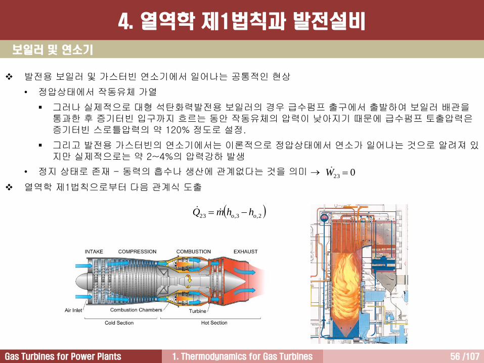
보일러 및 연소기
발전용 보일러 및 가스터빈 연소기에서 일어나는 공통적인 현상
• 정압상태에서 작동유체 가열
그러나 실제적으로 대형 석탄화력발전용 보일러의 경우 급수펌프 출구에서 출발하여 보일러 배관을통과한 후 증기터빈 입구까지 흐르는 동안 작동유체의 압력이 낮아지기 때문에 급수펌프 토출압력은증기터빈 스로틀압력의 약 120% 정도로 설정.
그리고 발전용 가스터빈의 연소기에서는 이론적으로 정압상태에서 연소가 일어나는 것으로 알려져 있지만 실제적으로는 약 2~4%의 압력강하 발생
• 정지 상태로 존재 - 동력의 흡수나 생산에 관계없다는 것을 의미
열역학 제1법칙으로부터 다음 관계식 도출
023 W
2,3,23 oo hhmQ
4. 열역학 제1법칙과 발전설비

1. Thermodynamics for Gas Turbines 57 /107Gas Turbines for Power Plants
터빈 [1/2]
터빈에서 일어나는 과정은 단열과정 이유?
단열과정:
열역학 제1법칙:
034 q
4,3,12 oo hhmW
700 kg/s,
1,250C1
2 34
550C
4. 열역학 제1법칙과 발전설비
1. Thermodynamics for Gas Turbines 58 /107Gas Turbines for Power Plants
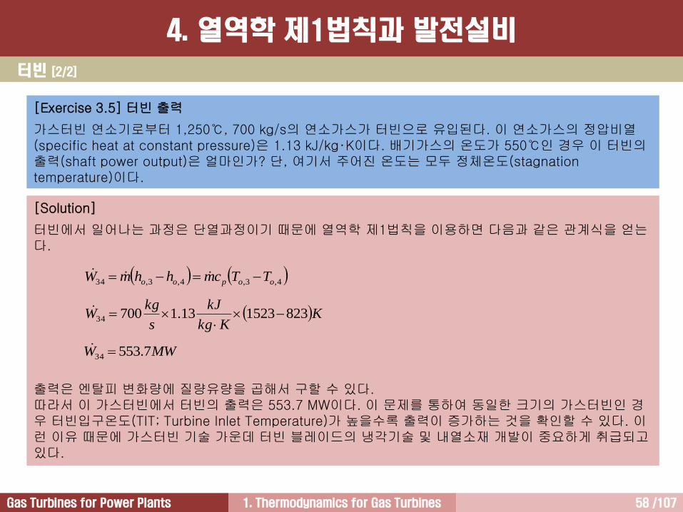
[Exercise 3.5] 터빈 출력
가스터빈 연소기로부터 1,250℃, 700 kg/s의 연소가스가 터빈으로 유입된다. 이 연소가스의 정압비열(specific heat at constant pressure)은 1.13 kJ/kg‧K이다. 배기가스의 온도가 550℃인 경우 이 터빈의출력(shaft power output)은 얼마인가? 단, 여기서 주어진 온도는 모두 정체온도(stagnation temperature)이다.
[Solution]
터빈에서 일어나는 과정은 단열과정이기 때문에 열역학 제1법칙을 이용하면 다음과 같은 관계식을 얻는다.
출력은 엔탈피 변화량에 질량유량을 곱해서 구할 수 있다.따라서 이 가스터빈에서 터빈의 출력은 553.7 MW이다. 이 문제를 통하여 동일한 크기의 가스터빈인 경우 터빈입구온도(TIT; Turbine Inlet Temperature)가 높을수록 출력이 증가하는 것을 확인할 수 있다. 이런 이유 때문에 가스터빈 기술 가운데 터빈 블레이드의 냉각기술 및 내열소재 개발이 중요하게 취급되고있다.
4,3,4,3,34 oopoo TTcmhhmW
KKkg
kJ
s
kgW 823152313.170034
MWW 7.55334
터빈 [2/2]
4. 열역학 제1법칙과 발전설비
1. Thermodynamics for Gas Turbines 59 /107Gas Turbines for Power Plants
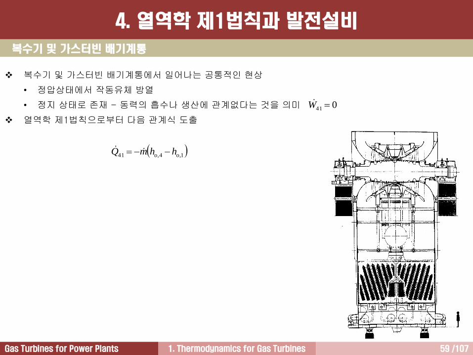
복수기 및 가스터빈 배기계통
복수기 및 가스터빈 배기계통에서 일어나는 공통적인 현상
• 정압상태에서 작동유체 방열
• 정지 상태로 존재 - 동력의 흡수나 생산에 관계없다는 것을 의미
열역학 제1법칙으로부터 다음 관계식 도출
041 W
1,4,41 oo hhmQ
4. 열역학 제1법칙과 발전설비
1. Thermodynamics for Gas Turbines 60 /107Gas Turbines for Power Plants
c
cp (1.4 for air)
Rc1
1
Rcp1
puh
RTuh
RdT
du
dT
dh
Rccp
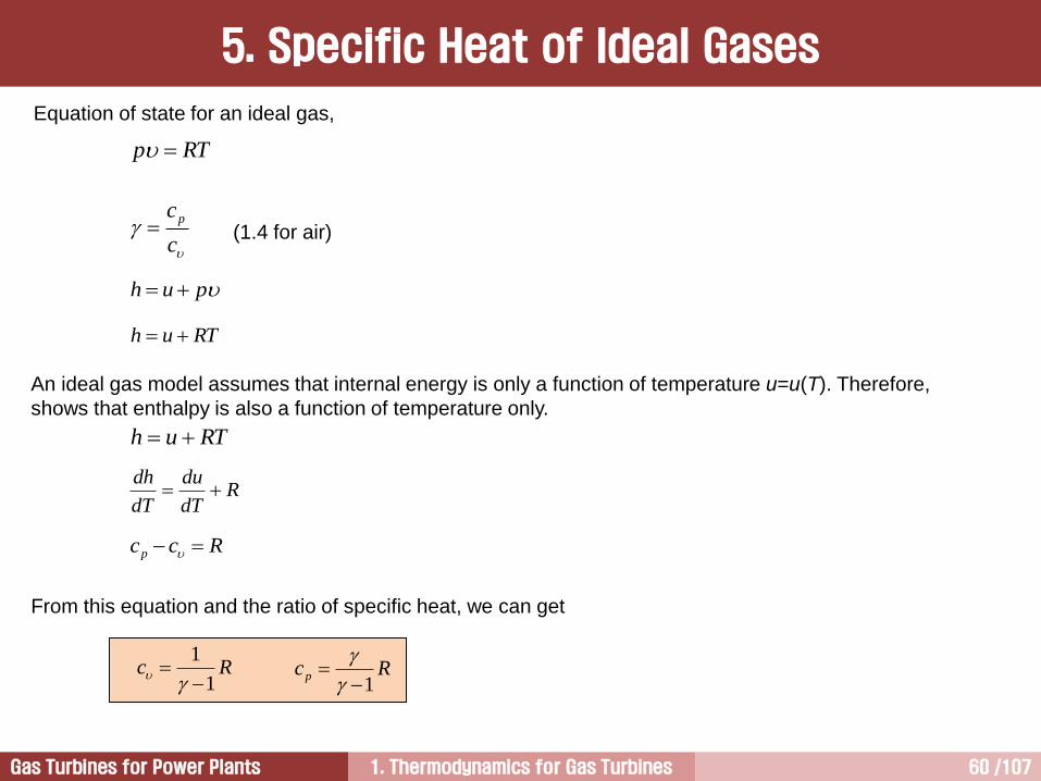
An ideal gas model assumes that internal energy is only a function of temperature u=u(T). Therefore,
shows that enthalpy is also a function of temperature only.
From this equation and the ratio of specific heat, we can get
RTuh
5. Specific Heat of Ideal Gases
Equation of state for an ideal gas,
RTp
1. Thermodynamics for Gas Turbines 61 /107Gas Turbines for Power Plants
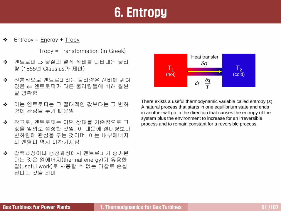
There exists a useful thermodynamic variable called entropy (s).
A natural process that starts in one equilibrium state and ends
in another will go in the direction that causes the entropy of the
system plus the environment to increase for an irreversible
process and to remain constant for a reversible process.
6. Entropy
T1(hot)
T2(cold)
qHeat transfer
T
qds
Entropy = Energy + Tropy
Tropy = Transformation (in Greek)
엔트로피 물질의 열적 상태를 나타내는 물리량 (1865년 Clausius가 제안)
전통적으로 엔트로피라는 물리량은 신비에 싸여있음 엔트로피가 다른 물리량들에 비해 훨씬덜 명확함
이는 엔트로피는 그 절대적인 값보다는 그 변화량에 관심을 두기 때문임
참고로, 엔트로피는 어떤 상태를 기준점으로 그값을 임의로 설정한 것임. 이 때문에 절대량보다변화량에 관심을 두는 것이며, 이는 내부에너지와 엔탈피 역시 마찬가지임
압축과정이나 팽창과정에서 엔트로피가 증가된다는 것은 열에너지(thermal energy)가 유용한일(useful work)로 사용할 수 없는 마찰로 손실된다는 것을 의미
1. Thermodynamics for Gas Turbines 62 /107Gas Turbines for Power Plants
A
uA
sA
B
uB
sB
A B
q
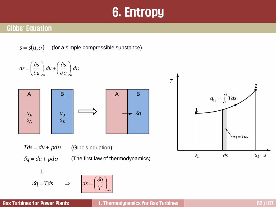
,uss
ds
duu
sds
u
pdduTds
Tdsq
Gibbs Equation
pdduq
(Gibb’s equation)
(The first law of thermodynamics)
T
s
2
1
s2s1 ds
2
112 Tdsq
Tdsq
revT
qds
(for a simple compressible substance)
6. Entropy

1. Thermodynamics for Gas Turbines 63 /107Gas Turbines for Power Plants
정량적 계산
From Gibbs’ equation and first law of thermodynamics,
and integrating. This gives
Entropy is assigned the value zero at the reference state, Tref = 0 K and pref = 1 atm. The value of entropy at
temperature T and pressure p is then calculated from
p
dpR
T
dTcds
dpdhTds
p
1
21122 ln,,
12
p
pR
T
dTTc
T
dTTcpTspTs
T
Tp
T
Tp
refref
ref
T
Tp
p
pR
T
dTTcpTs
ref
ln,
6. Entropy
1. Thermodynamics for Gas Turbines 64 /107Gas Turbines for Power Plants
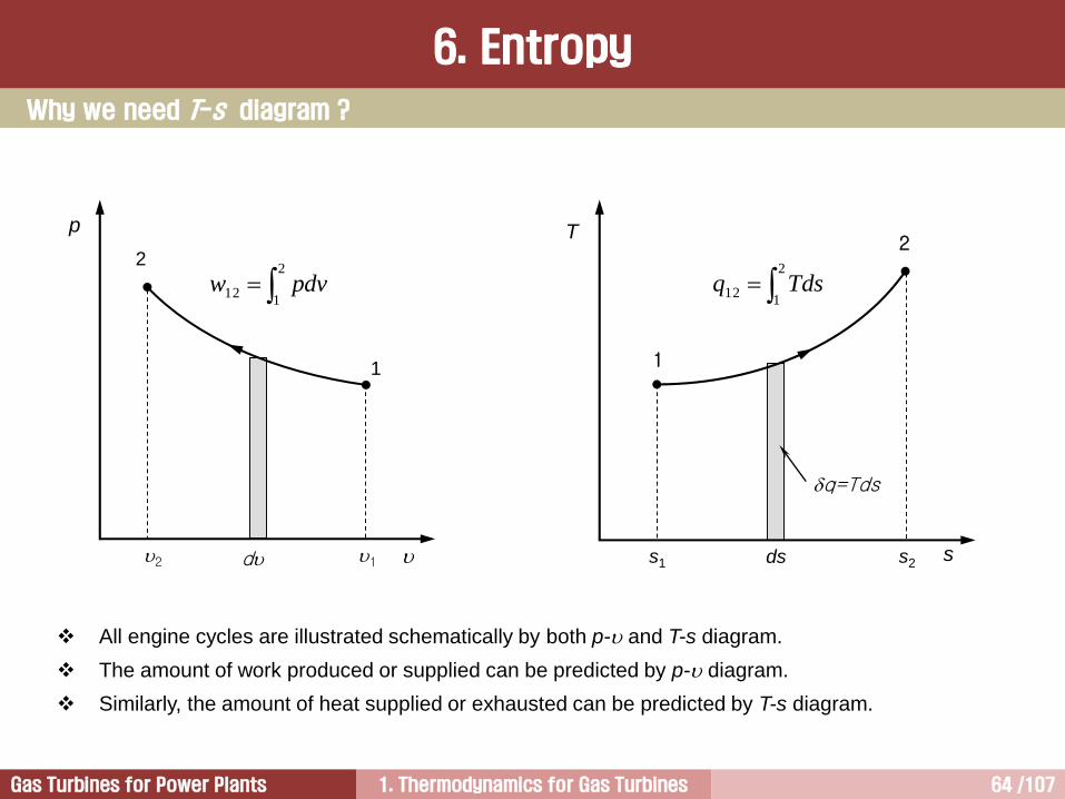
All engine cycles are illustrated schematically by both p- and T-s diagram.
The amount of work produced or supplied can be predicted by p- diagram.
Similarly, the amount of heat supplied or exhausted can be predicted by T-s diagram.
2
112 pdvw
p
2
1
12 d
2
112 Tdsq
T
s
2
1
s2s1 ds
q=Tds
Why we need T-s diagram ?
6. Entropy

1. Thermodynamics for Gas Turbines 65 /107Gas Turbines for Power Plants
Rankine Cycle
T
s
1
2
3
4qout
T
s
2
3
qin
14
T
s
12
3
4
qsys
(a) (b) (c)
T-s diagram
6. Entropy

1. Thermodynamics for Gas Turbines 66 /107Gas Turbines for Power Plants
Otto Cycle / Diesel Cycle / Brayton Cycle
과정의 s-축에 대한 투영면적이 계로 공급되거나 계를 빠져나간 열량을 나타냄
엔트로피가 증가하면 계 내부로 열량 공급, 엔트로피가 감소하면 계 외부로 열량 배출 의미
(a) (b) (c)
T
s
2
1
3
4
qin
T
s
2
1
3
4
qout
T
s
2
1
3
4qsys
T-s diagram
6. Entropy

1. Thermodynamics for Gas Turbines 67 /107Gas Turbines for Power Plants
p
p = const.
adiabatic
T
s
=
co
nst.
T = const.
T = const.
s=
co
nst.
(ad
iab
atic)
= const.
p = const.
p- and T-s Diagrams
6. Entropy
1. Thermodynamics for Gas Turbines 68 /107Gas Turbines for Power Plants
Isentropic Efficiency & Loss
6. Entropy
Ava
ilab
le e
ne
rgy
Use
ful e
ne
rgy
A
BC
D
pi
po
Lossds
Reduction in useful energy
(Performance degradation)
Increase in entropy due to aging
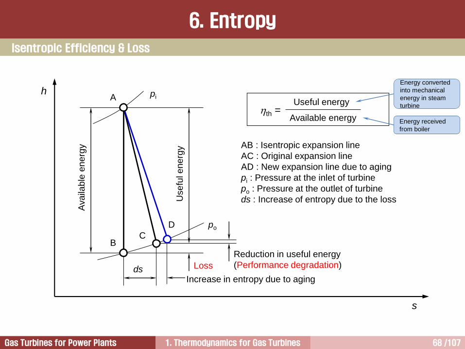
AB : Isentropic expansion line
AC : Original expansion line
AD : New expansion line due to aging
pi : Pressure at the inlet of turbine
po : Pressure at the outlet of turbine
ds : Increase of entropy due to the loss
h
s
th =Useful energy
Available energy Energy received
from boiler
Energy converted
into mechanical
energy in steam
turbine

1. Thermodynamics for Gas Turbines 69 /107Gas Turbines for Power Plants
dT
qds
= entropy increase by heat transfer
= entropy increase due to internal irreversibility, such as friction
T
q
d
T
LWd
= lost workLW
Friction is ignored in thermodynamics, thus this equation is not used generally. However, isentropic
process can be expressed very clearly by this equation.
The Second Law of Thermodynamics
6. Entropy

1. Thermodynamics for Gas Turbines 70 /107Gas Turbines for Power Plants
12
12
12
12
TT
TT
hh
hh ssC
ss
TTT
TT
hh
hh
43
43
43
43
Efficiency of compressor (or pump)
Efficiency of turbine
Efficiency
6. Entropy
T
s
1
22s
3
4s 4
[ Brayton cycle T-s diagram ]

1. Thermodynamics for Gas Turbines 71 /107Gas Turbines for Power Plants
① 보일러(HRSG)급수펌프에서 다양한 손실 발생 – 펌프 자체효율 존재
② 보일러는 보일러 배관에서 발생하는 마찰손실, 외벽을 통해 빠져나가는 열손실, 연도가스 통로 압력손실, 굴뚝으로 빠져나가는 열손실, 보일러 자체의 열전달 효율이 존재 - 보일러 자체효율 존재
③ 가스터빈/증기터빈에서 다양한 손실 발생 – 가스터빈/증기터빈 자체효율 존재
④ 복수기 손실 발생
⑤ 기계적 손실 발생 – 가스터빈/증기터빈에서 생산된 동력이 발전기에 전달되면서 베어링에서 기계적 손실발생
⑥ 발전기 자체효율(대개 98~99%) 존재 – 전기적 손실 및 기계적 손실
⑦ 발전소 보조기기(오일펌프, 팬 등)에 사용되는 전력 존재
복합발전에서 Heat Rate를 사용하는 이유
Heat rate는 열입력을 발전기 출력으로 나눈 값
Heat rate는 열효율과 역수 관계
실질적으로 다양한 손실을 반영하여 정확하게 효율을 계산
하기 어려움
7. Heat Rate

1. Thermodynamics for Gas Turbines 72 /107Gas Turbines for Power Plants
1 kcal = 물(water) 1 kg의 온도를 1C 상승시키는데 필요한 열량
1 Btu = 물(water) 1 lb의 온도를 1F 상승시키는데 필요한 열량
1 kcal = 427 kgfm = 427 kg 9.81 m/s2 m = 4185 Nm = 4.185 kJ
1 Btu = 1 kcal 1/2.204619 5/9 = 0.252 kcal = 1.055 kJ
양변을 시간 h로 나누면,
1 Btu/h = 1.055 kJ/3600 s = 1.055/3600 kW
1 kWh = 3600/1.055 Btu = 3412.14 Btu
따라서 이상적인 경우(열효율 100%)에 1 kWh의 전기를 생산하기 위해서는 3412.14 Btu의 열량이
필요. 그러나 실제적으로는 다양한 손실로 인하여 1 kWh의 전기를 생산하기 위해서는 이상적인
경우보다 더 많은 열량이 요구.
]kJ/kWhorBtu/kWh,[outputgenerator
inputheatrateheat
발전설비 열효율은 각 구성품에서 발생하는 비가역성으로 인하여 계산하기 어렵다. 따라서 열효율 대신에 열입력을 발전기 출력으로 나누어준 열율을 많이 사용
]kJ/kWh[
3600
]Btu/kWh[
14.3412
rateheatrateheatth 열율과 열효율 관계:
7. Heat Rate
1. Thermodynamics for Gas Turbines 73 /107Gas Turbines for Power Plants
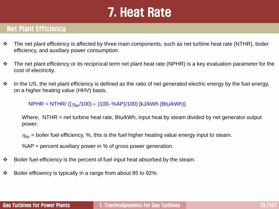
The net plant efficiency is affected by three main components, such as net turbine heat rate (NTHR), boiler
efficiency, and auxiliary power consumption.
The net plant efficiency or its reciprocal term net plant heat rate (NPHR) is a key evaluation parameter for the
cost of electricity.
In the US, the net plant efficiency is defined as the ratio of net generated electric energy by the fuel energy,
on a higher heating value (HHV) basis.
NPHR = NTHR/ ((Blr/100) (100%AP)/100) [kJ/kWh (Btu/kWh)]
Where, NTHR = net turbine heat rate, Btu/kWh, input heat by steam divided by net generator output
power.
Blr = boiler fuel efficiency, %, this is the fuel higher heating value energy input to steam.
%AP = percent auxiliary power in % of gross power generation.
Boiler fuel efficiency is the percent of fuel input heat absorbed by the steam.
Boiler efficiency is typically in a range from about 85 to 92%.
Net Plant Efficiency
7. Heat Rate

1. Thermodynamics for Gas Turbines 74 /107Gas Turbines for Power Plants
C + O2 = CO2 + 33.9 MJ/kg
H2 + 1/2O2 = H2O(water) + 143.0 MJ/kg (HHV)
H2 + 1/2O2 = H2O(vapor) + 120.6 MJ/kg (LHV)
S + O2 = SO2 + 9.28 MJ/kg
Combustion
7. Heat Rate
1. Thermodynamics for Gas Turbines 75 /107Gas Turbines for Power Plants
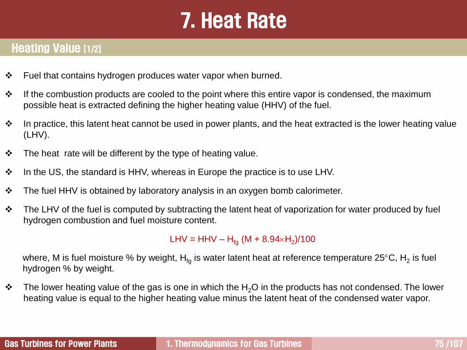
Fuel that contains hydrogen produces water vapor when burned.
If the combustion products are cooled to the point where this entire vapor is condensed, the maximum
possible heat is extracted defining the higher heating value (HHV) of the fuel.
In practice, this latent heat cannot be used in power plants, and the heat extracted is the lower heating value
(LHV).
The heat rate will be different by the type of heating value.
In the US, the standard is HHV, whereas in Europe the practice is to use LHV.
The fuel HHV is obtained by laboratory analysis in an oxygen bomb calorimeter.
The LHV of the fuel is computed by subtracting the latent heat of vaporization for water produced by fuel
hydrogen combustion and fuel moisture content.
LHV = HHV – Hfg (M + 8.94H2)/100
where, M is fuel moisture % by weight, Hfg is water latent heat at reference temperature 25C, H2 is fuel
hydrogen % by weight.
The lower heating value of the gas is one in which the H2O in the products has not condensed. The lower
heating value is equal to the higher heating value minus the latent heat of the condensed water vapor.
Heating Value [1/2]
7. Heat Rate
1. Thermodynamics for Gas Turbines 76 /107Gas Turbines for Power Plants
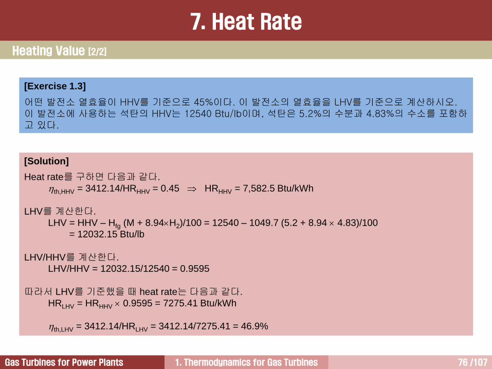
[Exercise 1.3]
어떤 발전소 열효율이 HHV를 기준으로 45%이다. 이 발전소의 열효율을 LHV를 기준으로 계산하시오. 이 발전소에 사용하는 석탄의 HHV는 12540 Btu/lb이며, 석탄은 5.2%의 수분과 4.83%의 수소를 포함하고 있다.
[Solution]
Heat rate를 구하면 다음과 같다.
th,HHV = 3412.14/HRHHV = 0.45 HRHHV = 7,582.5 Btu/kWh
LHV를 계산한다.
LHV = HHV – Hfg (M + 8.94H2)/100 = 12540 – 1049.7 (5.2 + 8.94 4.83)/100
= 12032.15 Btu/lb
LHV/HHV를 계산한다.
LHV/HHV = 12032.15/12540 = 0.9595
따라서 LHV를 기준했을 때 heat rate는 다음과 같다.
HRLHV = HRHHV 0.9595 = 7275.41 Btu/kWh
th,LHV = 3412.14/HRLHV = 3412.14/7275.41 = 46.9%
Heating Value [2/2]
7. Heat Rate
1. Thermodynamics for Gas Turbines 77 /107Gas Turbines for Power Plants
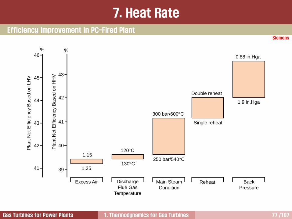
Siemens
46
45
44
43
42
41
43
42
41
40
39
% %
1.15
1.25
120C
130C
300 bar/600C
250 bar/540C
Single reheat
Double reheat
1.9 in.Hga
0.88 in.Hga
Excess Air Discharge
Flue Gas
Temperature
Main Steam
ConditionReheat Back
Pressure
Pla
nt N
et
Eff
icie
ncy B
ase
d o
n L
HV
Pla
nt N
et
Eff
icie
ncy B
ase
d o
n H
HV
Efficiency Improvement in PC-Fired Plant
7. Heat Rate
1. Thermodynamics for Gas Turbines 78 /107Gas Turbines for Power Plants
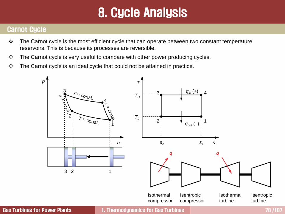
8. Cycle Analysis
p
2
1
3
4
2 13
T
s
12
3 4TH
TL
qout ()
qin (+)
s2 s1
The Carnot cycle is the most efficient cycle that can operate between two constant temperature
reservoirs. This is because its processes are reversible.
The Carnot cycle is very useful to compare with other power producing cycles.
The Carnot cycle is an ideal cycle that could not be attained in practice.
Isothermal
compressor
Isentropic
compressor
Isothermal
turbine
Isentropic
turbine
q q
Carnot Cycle

1. Thermodynamics for Gas Turbines 79 /107Gas Turbines for Power Plants
Process Work Heat
12 Compression at constant temp. w12 = RT1 ln(1/2) (= win) q12 = w12 = T1(s1s2) (= qout)
23 Adiabatic compression w23 = (u3u2) = c(T3T2) (= win) q23 = 0
34 Expansion at constant temp. w34 = RT3 ln(4/3) (= wout) q34 = w34 = T3(s4s3) (= qin)
41 Adiabatic expansion w41 = u4u1 = c(T4T1) (= wout) q41 = 0
wduq
in
out
in
outin
in
sys
in
sys
thq
q
q
q
q
q
w
input
output
1
H
LCarnotth
T
T
T
T
ssT
ssT
111
3
1
343
211,
8. Cycle Analysis
Carnot Cycle
41342312 wwwwwwOutput sys
[Exercise 1.4]
카르노사이클 열효율 향상방법 두 가지를 제시하시오.1)2)
121212 wuuq
1. Thermodynamics for Gas Turbines 80 /107Gas Turbines for Power Plants
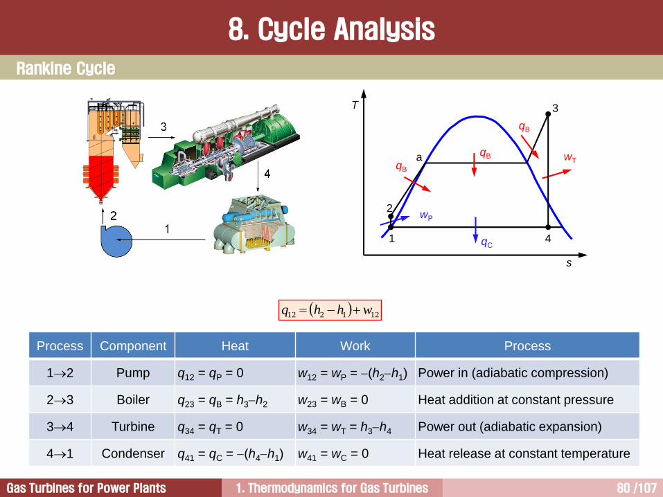
T
s
1
2
3
4qC
wTqB
qB
qB
wP
a
Process Component Heat Work Process
12 Pump q12 = qP = 0 w12 = wP = (h2h1) Power in (adiabatic compression)
23 Boiler q23 = qB = h3h2 w23 = wB = 0 Heat addition at constant pressure
34 Turbine q34 = qT = 0 w34 = wT = h3h4 Power out (adiabatic expansion)
41 Condenser q41 = qC = (h4h1) w41 = wC = 0 Heat release at constant temperature
Rankine Cycle
8. Cycle Analysis
121212 whhq

1. Thermodynamics for Gas Turbines 81 /107Gas Turbines for Power Plants
Process Component Heat Work Process
12 Compressor q12 = qC = 0 w12 = wC = (h2h1) Power in (adiabatic compression)
23 Combustor q23 = qB = h3h2 w23 = wB = 0 Heat addition at constant pressure
34 Turbine q34 = qT = 0 w34 = wT = h3h4 Power out (adiabatic expansion)
41 Exhaust q41 = qE = (h4h1) w41 = wE = 0 Heat release at constant pressure
121212 whhq
p
2
1
T
(h)
s
qin
3
41
2
3
4
qout
win
wout
win
wout
qin
qout
Brayton Cycle
8. Cycle Analysis

1. Thermodynamics for Gas Turbines 82 /107Gas Turbines for Power Plants
Steam is used in more of today’s power plants than any other working fluid.
The physical properties of steam are complex because any one steam property is changed, such as pressure,
temperature, specific volume, energy or moisture, all the other properties will also change.
The Mollier diagram has been developed to show this interrelationship of steam properties, and how they all
fit together.
The vertical axis is enthalpy(kJ/kg or BTU/lb) which is defined as internal energy plus flow energy of the
working fluid, and the horizontal axis is entropy(kJ/kg-K or BTU/lb-F) representing energy loss.
Mollier diagram shows lines of constant pressure, constant temperature, constant moisture, and the steam
saturation line (below which the steam is wet, and above which the steam is dry and superheated.
h-s Diagram [Mollier Diagram]
8. Cycle Analysis
h-s 선도는 이상기체와 다른 성질을 가지는 실재기체의 상태변화를 실험을 통하여 확인하여 표와 선도로 나타낸 것이다.
h-s 선도는 1906년 R. Mollier가 개발
h를 종축, s를 횡축으로 설정하여 증기의 상태(p, , T, x)를 나타낸 선도.
증기의 상태량(T, p, , x, h, s) 가운데 2개를 알면, h-s 선도로부터 다른 상태량을 알 수 있다.
주로 연소기체나 수증기를 대상으로 하기 때문에 가스터빈 및 증기터빈의 사이클 해석에 이용된다.
압축수의 엔탈피는 파악하기 어렵다.

1. Thermodynamics for Gas Turbines 83 /107Gas Turbines for Power Plants
h-s Diagram [Mollier Diagram]
8. Cycle Analysis

1. Thermodynamics for Gas Turbines 84 /107Gas Turbines for Power Plants
Wilson line
T
(h)
s
1
2
3
4
win
wout
qin
qout
h-s Diagram [Mollier Diagram]
8. Cycle Analysis
[Exercise 1.5]
작동유체가 공기(이상기체)인 경우 T-s 선도와 h-s 선도가 동일한 형상을 가지는 이유에대해서 설명하시오.
1. Thermodynamics for Gas Turbines 85 /107Gas Turbines for Power Plants
Pre
ssu
re P
1 2
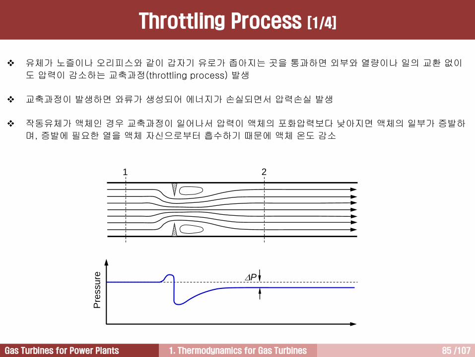
Throttling Process [1/4]
유체가 노즐이나 오리피스와 같이 갑자기 유로가 좁아지는 곳을 통과하면 외부와 열량이나 일의 교환 없이
도 압력이 감소하는 교축과정(throttling process) 발생
교축과정이 발생하면 와류가 생성되어 에너지가 손실되면서 압력손실 발생
작동유체가 액체인 경우 교축과정이 일어나서 압력이 액체의 포화압력보다 낮아지면 액체의 일부가 증발하
며, 증발에 필요한 열을 액체 자신으로부터 흡수하기 때문에 액체 온도 감소
1. Thermodynamics for Gas Turbines 86 /107Gas Turbines for Power Plants
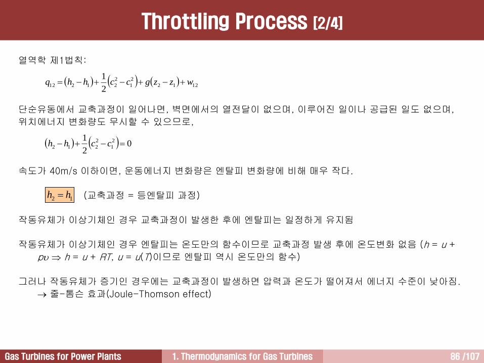
열역학 제1법칙:
단순유동에서 교축과정이 일어나면, 벽면에서의 열전달이 없으며, 이루어진 일이나 공급된 일도 없으며,
위치에너지 변화량도 무시할 수 있으므로,
속도가 40m/s 이하이면, 운동에너지 변화량은 엔탈피 변화량에 비해 매우 작다.
(교축과정 = 등엔탈피 과정)
작동유체가 이상기체인 경우 교축과정이 발생한 후에 엔탈피는 일정하게 유지됨
작동유체가 이상기체인 경우 엔탈피는 온도만의 함수이므로 교축과정 발생 후에 온도변화 없음 (h = u +
p h = u + RT, u = u(T)이므로 엔탈피 역시 온도만의 함수)
그러나 작동유체가 증기인 경우에는 교축과정이 발생하면 압력과 온도가 떨어져서 에너지 수준이 낮아짐.
줄-톰슨 효과(Joule-Thomson effect)
12 hh
1212
2
1
2
212122
1wzzgcchhq
02
1 2
1
2
212 cchh
Throttling Process [2/4]

1. Thermodynamics for Gas Turbines 87 /107Gas Turbines for Power Plants
[Exercise 1.6] Compare the velocity at 2
그림에서 A와 B는 동일한 규격의 도관이다. 도관 B에 오리피스를 설치하였다. 그리고 도관 B 입구압력은도관 A와 동일하게 유지시킨 상태에서 질량유량을 절반으로 줄였다. 그리고 이때 도관 B의 하류 2에서압력을 측정하였더니 입구 압력의 절반이었다. 이때 오리피스 하류 2에서 유속을 비교하시오.
1 2
A
1 2
B
Throttling Process [3/4]
1. Thermodynamics for Gas Turbines 88 /107Gas Turbines for Power Plants
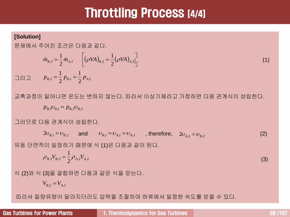
[Solution]
문제에서 주어진 조건은 다음과 같다.
(1)
그리고
교축과정이 일어나면 온도는 변하지 않는다. 따라서 이상기체라고 가정하면 다음 관계식이 성립한다.
그러므로 다음 관계식이 성립한다.
and , therefore, (2)
유동 단면적이 일정하기 때문에 식 (1)은 다음과 같이 된다.
(3)
식 (2)와 식 (3)을 결합하면 다음과 같은 식을 얻는다.
따라서 질량유량이 달라지더라도 압력을 조절하여 하류에서 일정한 속도를 얻을 수 있다.
2,2,2,2,
2
1
2
1ABAB VAVAmm
1,1,2,2
1
2
1ABB ppp
2,2,1,1, BBBB pp
2,1,2 BB
2,2,2,2,2
1AABB VV
2,1,1, AAB 2,2,2 BA
2,2, AB VV
Throttling Process [4/4]
1. Thermodynamics for Gas Turbines 89 /107Gas Turbines for Power Plants
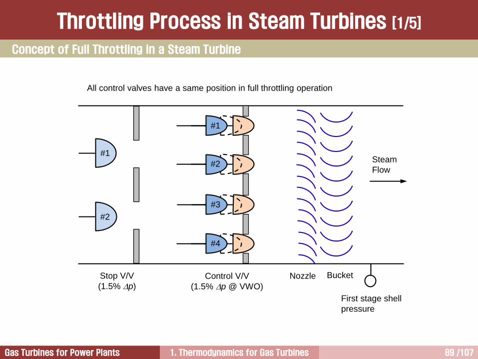
Throttling Process in Steam Turbines [1/5]
All control valves have a same position in full throttling operation
Control V/V
(1.5% p @ VWO)
Nozzle
First stage shell
pressure
Stop V/V
(1.5% p)
Bucket
Steam
Flow
#1
#2
#1
#2
#3
#4
Concept of Full Throttling in a Steam Turbine
1. Thermodynamics for Gas Turbines 90 /107Gas Turbines for Power Plants
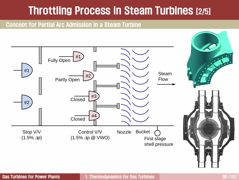
Control V/V
(1.5% p @ VWO)
Nozzle
First stage
shell pressure
Fully Open
Stop V/V
(1.5% p)
Partly Open
Closed
Bucket
#1
#2
#3
#4
Steam
Flow
#1
#2Closed
Concept for Partial Arc Admission in a Steam Turbine
Throttling Process in Steam Turbines [2/5]
1. Thermodynamics for Gas Turbines 91 /107Gas Turbines for Power Plants
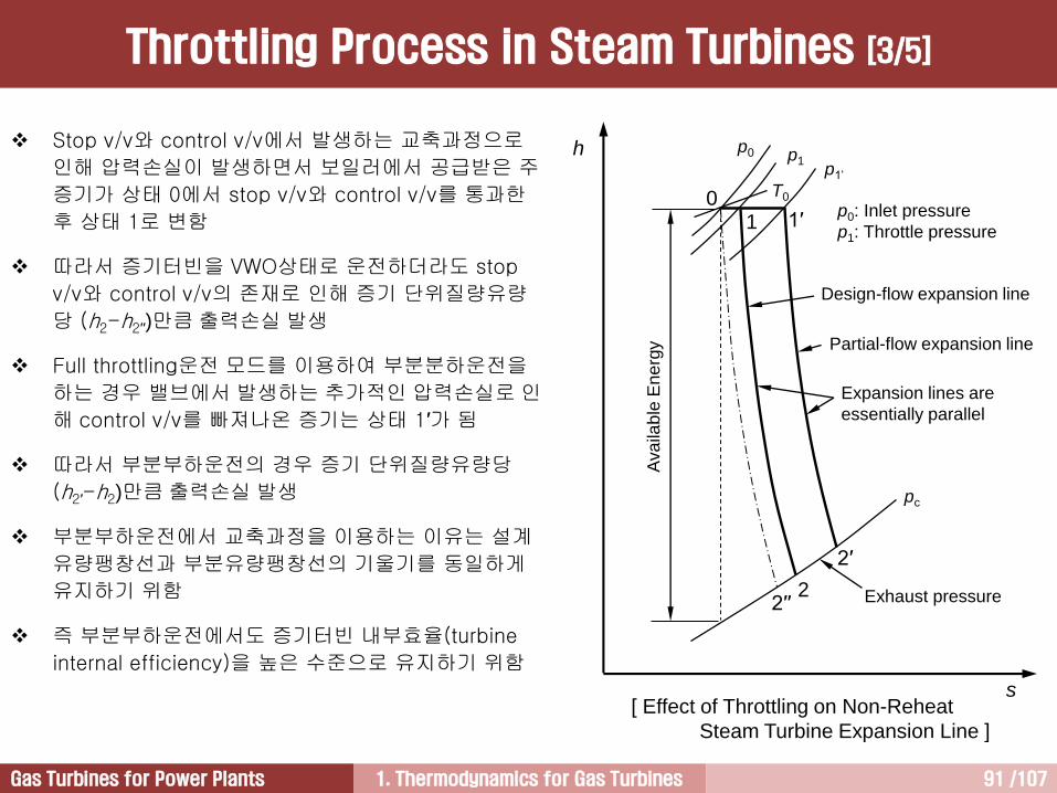
[ Effect of Throttling on Non-Reheat
Steam Turbine Expansion Line ]
p1
Ava
ilab
le E
ne
rgy
pc
p0
T0
h
s
Partial-flow expansion line
Expansion lines are
essentially parallel
Design-flow expansion line
Exhaust pressure
p1’
p0: Inlet pressure
p1: Throttle pressure1 1′
2′
2
0
2′′
Stop v/v와 control v/v에서 발생하는 교축과정으로
인해 압력손실이 발생하면서 보일러에서 공급받은 주
증기가 상태 0에서 stop v/v와 control v/v를 통과한
후 상태 1로 변함
따라서 증기터빈을 VWO상태로 운전하더라도 stop
v/v와 control v/v의 존재로 인해 증기 단위질량유량
당 (h2-h2′′)만큼 출력손실 발생
Full throttling운전 모드를 이용하여 부분분하운전을
하는 경우 밸브에서 발생하는 추가적인 압력손실로 인
해 control v/v를 빠져나온 증기는 상태 1′가 됨
따라서 부분부하운전의 경우 증기 단위질량유량당
(h2′-h2)만큼 출력손실 발생
부분부하운전에서 교축과정을 이용하는 이유는 설계
유량팽창선과 부분유량팽창선의 기울기를 동일하게
유지하기 위함
즉 부분부하운전에서도 증기터빈 내부효율(turbine
internal efficiency)을 높은 수준으로 유지하기 위함
Throttling Process in Steam Turbines [3/5]

1. Thermodynamics for Gas Turbines 92 /107Gas Turbines for Power Plants
U100% load
Nozzle Row
25% load
100%
25%
Bucket Row
U
75% load50% load
[ Velocity Diagram at Various Loads ]
A turbine has different expansion lines as
the load is decreased.
But the part load expansion lines are
generally parallel to the full load
expansion line.
This means that the internal efficiency
under part load conditions is very close
to that under full load conditions. That is,
design efficiency of the turbine blades is
maintained during part load operations
by using the control valve.
However, the cycle efficiency is reduced
under part load conditions.
Throttling Process in Steam Turbines [4/5]
1. Thermodynamics for Gas Turbines 93 /107Gas Turbines for Power Plants
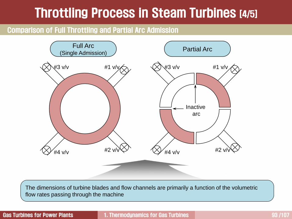
Full Arc(Single Admission)
Partial Arc
The dimensions of turbine blades and flow channels are primarily a function of the volumetric
flow rates passing through the machine
Inactive
arc
#1 v/v
#2 v/v#4 v/v
#3 v/v#1 v/v
#2 v/v#4 v/v
#3 v/v
Comparison of Full Throttling and Partial Arc Admission
Throttling Process in Steam Turbines [4/5]
1. Thermodynamics for Gas Turbines 94 /107Gas Turbines for Power Plants
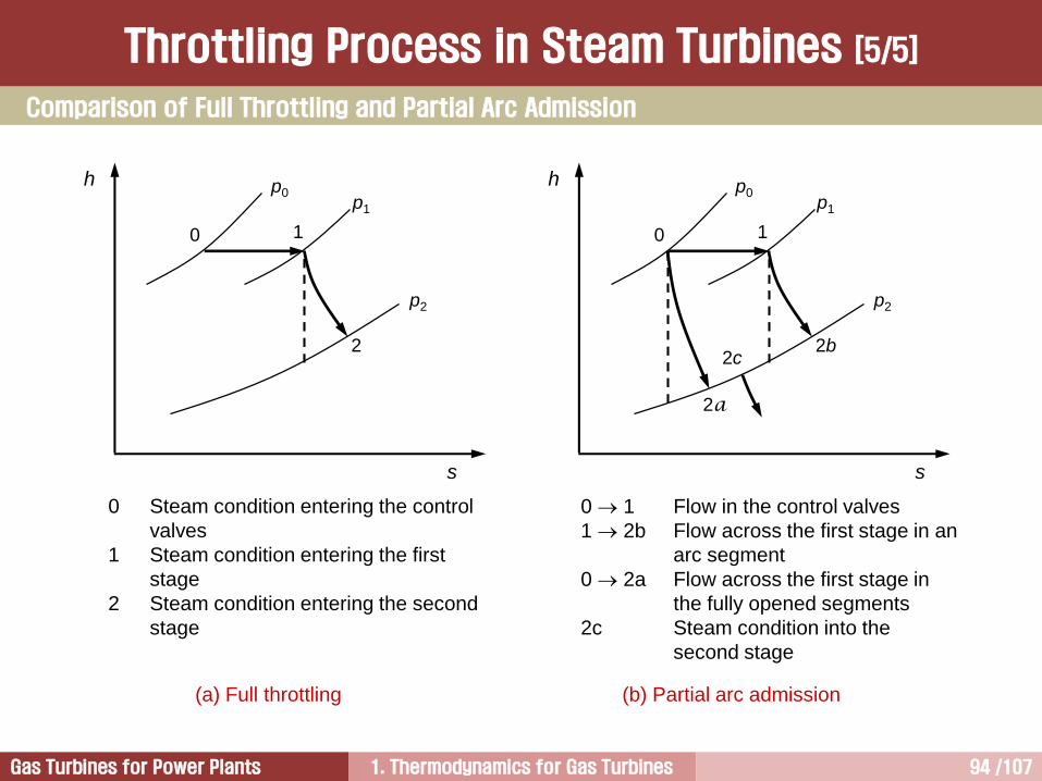
(a) Full throttling (b) Partial arc admission
0
h
s
1
2a
p0p1
p2
2b2c
0
h
s
1
p0p1
p2
2
0 1 Flow in the control valves
1 2b Flow across the first stage in an
arc segment
0 2a Flow across the first stage in
the fully opened segments
2c Steam condition into the
second stage
0 Steam condition entering the control
valves
1 Steam condition entering the first
stage
2 Steam condition entering the second
stage
Throttling Process in Steam Turbines [5/5]
Comparison of Full Throttling and Partial Arc Admission
1. Thermodynamics for Gas Turbines 95 /107Gas Turbines for Power Plants
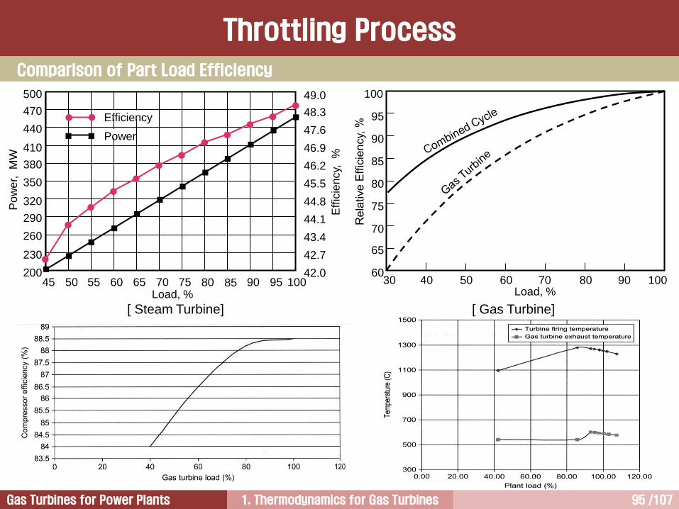
Throttling Process
Load, %30 40 50 60 70 80 90 100
65
60
75
70
85
80
95
90
100
49.0
48.3
47.6
46.9
46.2
45.5
44.8
44.1
43.4
42.7
42.045 50 55 60 65 70 75 80 85 90 95 100
200
500
470
440
410
380
350
320
290
260
230
Load, %
Eff
icie
ncy,
%
Po
we
r, M
W
Power
Efficiency
Comparison of Part Load Efficiency
[ Gas Turbine][ Steam Turbine]
1. Thermodynamics for Gas Turbines 96 /107Gas Turbines for Power Plants
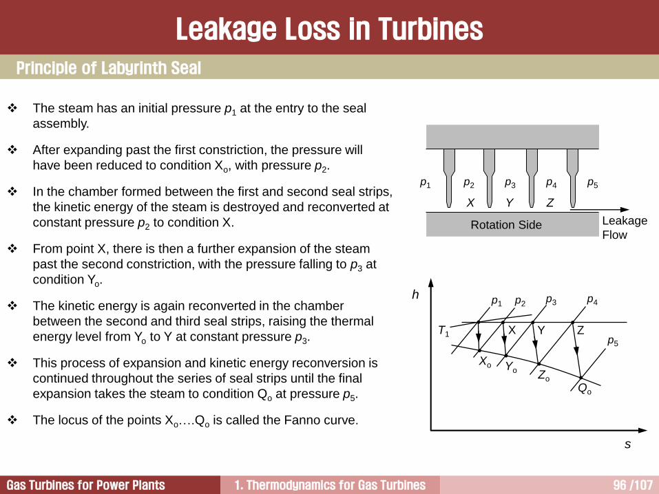
Leakage Loss in Turbines
Principle of Labyrinth Seal
The steam has an initial pressure p1 at the entry to the seal
assembly.
After expanding past the first constriction, the pressure will
have been reduced to condition Xo, with pressure p2.
In the chamber formed between the first and second seal strips,
the kinetic energy of the steam is destroyed and reconverted at
constant pressure p2 to condition X.
From point X, there is then a further expansion of the steam
past the second constriction, with the pressure falling to p3 at
condition Yo.
The kinetic energy is again reconverted in the chamber
between the second and third seal strips, raising the thermal
energy level from Yo to Y at constant pressure p3.
This process of expansion and kinetic energy reconversion is
continued throughout the series of seal strips until the final
expansion takes the steam to condition Qo at pressure p5.
The locus of the points Xo….Qo is called the Fanno curve.
h
s
T1
p1 p2p3 p4
p5
Xo YoZo
Qo
X Y Z
Leakage
Flow
p1 p2 p3 p4 p5
X Y Z
Rotation Side

1. Thermodynamics for Gas Turbines 97 /107Gas Turbines for Power Plants
Seal을 통해 누설되는 증기는 seal
strips을 통과하면서 교축과정이 발생
하기 때문에 실을 빠져나온 증기는 압
력이 낮아져서 가용에너지 크기가 작
아짐
따라서 누설증기가 다음 단에서 주유
동과 합류하더라도 주유동의 에너지
수준을 높이지 못하기 때문에 손실 발
생 누설손실
즉 누설증기가 실을 빠져나오면서 에
너지를 잃지 않았다면 다음 단에서 사
용할 수 있지만 이미 잃어버렸기 때문
에 손실 발생
따라서 누설손실을 줄이는 방법은 작
동유체의 누설량을 줄이는 것이며, 이
를 위해 브러시실과 같은 첨단 실이
각종 터빈에 적용되고 있다.
Brush Seal

1. Thermodynamics for Gas Turbines 98 /107Gas Turbines for Power Plants
Since bristles are extruded at an angle relative to the radial direction
of the shaft, the seal closes as soon as pressure is applied and even
if the brush seal is built in with an initial gap between rotor and
bristles.
This “blow-down effect” account for the more than 50% reduction in
leakage flow compared to standard labyrinth seals.
The flexible nature of the bristle pack allows for sufficient relative
movement of rotating and stationary parts during transient operation,
while the clearance between hard parts can even be increased by the
use of brush seals.
While a single brush row withstands more than 10 bar pressure
difference, several adjacent rows to be used to seal higher pressure
drops.
Multiple stage brush seals are already being used in turbines since
several years.
Brush seal has also been applied to gland seal system for large
steam turbines.
Flow
Bristle
Pack
Backing
Plate
Fence
Height
Brush Seal

1. Thermodynamics for Gas Turbines 99 /107Gas Turbines for Power Plants
Incorporating the brush seal element into a
spring-back packing provides additional
compliance in the event of a shaft rub.
This feature is expected to extend the life of the
bristle pack by reducing the likelihood of a hard
rub that can damage the bristles due to
excessive bristle deflection, overheating, or wear.
Retractable brush seals have been used in both
nuclear and fossil steam turbines.
Brush Seal

1. Thermodynamics for Gas Turbines 100 /107Gas Turbines for Power Plants
Gland Seal Packing (Brush Seal)
Brush Seal
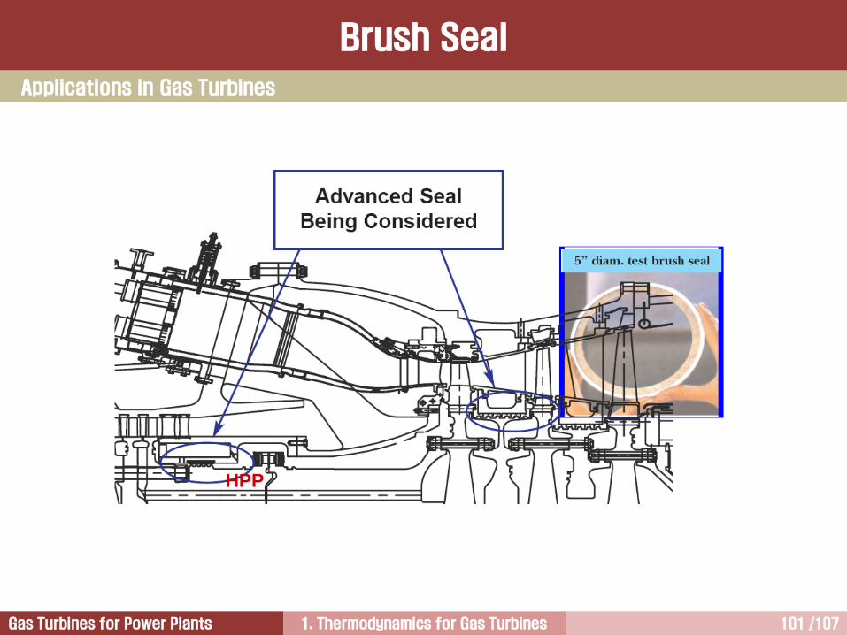
1. Thermodynamics for Gas Turbines 101 /107Gas Turbines for Power Plants
HPP
Applications in Gas Turbines
Brush Seal

1. Thermodynamics for Gas Turbines 102 /107Gas Turbines for Power Plants
HPP (High Pressure Packing)
Brush Seal
In general, a rub of 20 mils on the labyrinth seal
teeth equates to at least 1.0% loss in unit
performance.
To increase unit performance and to reduce the
rate of performance degradation due to the wear
on labyrinth seal teeth, a new wire brush seal
design has been developed.
Since the wire brush seal is flexible and will bend
(not wear) on contact with the compressor aft shaft,
a closer clearance can be allowed for the initial
installation.
Since the wire brush seal will “bounce back” to its
original configuration after a “rub”, there will be
substantially less performance degradation for the
labyrinth seal.
Performance improvement by replacement of
labyrinth seal into brush seal is normally about 1%
output and 0.5% heat rate.

1. Thermodynamics for Gas Turbines 103 /107Gas Turbines for Power Plants
Brush Seal in #2 Bearing of Gas Turbine
Brush Seal
1. Thermodynamics for Gas Turbines 104 /107Gas Turbines for Power Plants
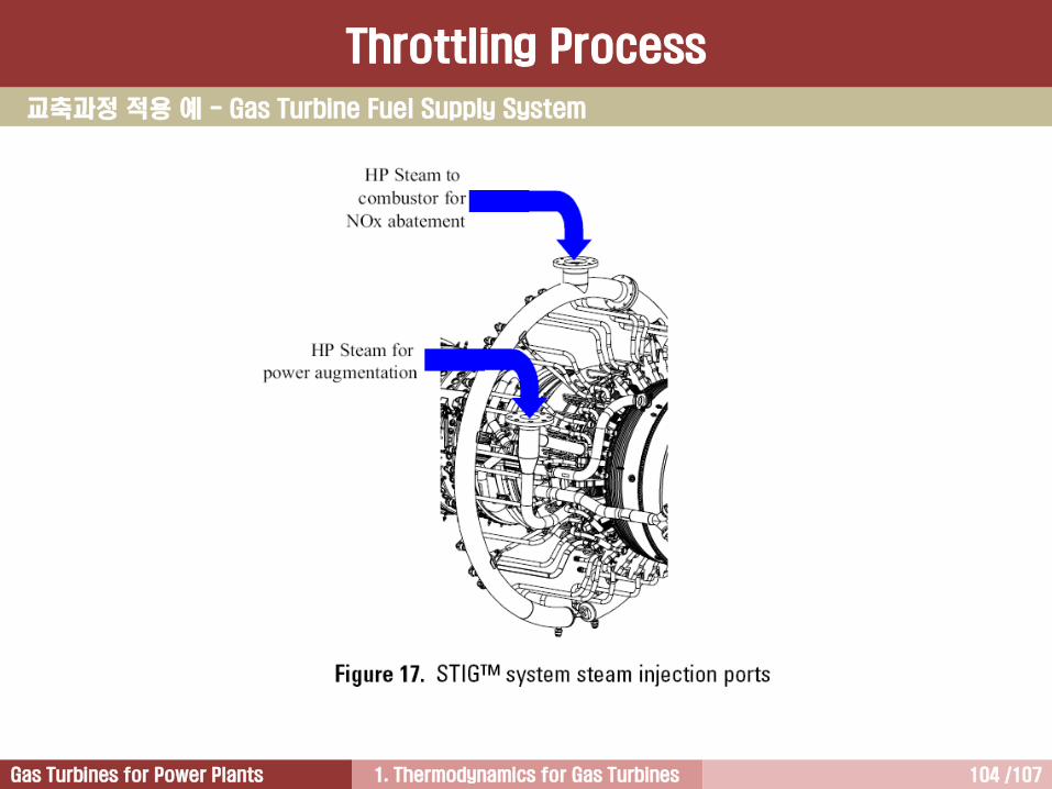
교축과정 적용 예 - Gas Turbine Fuel Supply System
Throttling Process
1. Thermodynamics for Gas Turbines 105 /107Gas Turbines for Power Plants
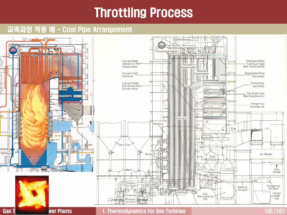
교축과정 적용 예 - Coal Pipe Arrangement
Throttling Process

1. Thermodynamics for Gas Turbines 106 /107Gas Turbines for Power Plants
Pulverizers
Coal Piping
Coal Burners
Throttling Process
교축과정 적용 예 - Coal Pipe Arrangement

1. Thermodynamics for Gas Turbines 107 /107Gas Turbines for Power Plants
질의 및 응답
작성자: 이 병 은작성일: 2016.6.21 (Ver.7)연락처: [email protected]: 010-3122-2262저서: 실무 발전설비 열역학
증기터빈 열유체기술발전용 가스터빈


![2018학년도 전기(1, 2차) 외국인 신입학 특별전형 학생모집안내KO]Spring 2018_Admission... · ※ 2020학년도 전기 모집부터 부모 중 1인만 대만 국적을](https://static.fdocument.pub/doc/165x107/5e1487f6d45ece2b7463b979/2018ee-e1-2-e-e-fee.jpg)