Conceptual Design of Mars Airplane
6
Trans. JSASS Aerospace Tech. Japan Vol. 10, No. ists28, pp. Te_5-Te_10, 2012 Topics Copyright© 2012 by the Japan Society for Aeronautical and Space Sciences and ISTS. All rights reserved. Te_5 Conceptual Design of Mars Airplane By Koji FUJITA 1) , Remi LUONG 2) , Hiroki NAGAI 1) and Keisuke ASAI 1) 1) Department of Aerospace Engineering, Tohoku University, Sendai, Japan 2) Masters of Science in Space Studies, International Space University, Illkirch-Graffenstaden, France The presence of an atmosphere on Mars signifies that an aircraft could travel in its atmosphere using the aerodynamic forces of flight. A reconnaissance aircraft offers the possibility to obtain high resolution data on a regional scale of several hundreds to thousands of kilometers, which cannot be achieved with rovers or satellites. However, conventional aircraft design cannot be applied for a Mars Airplane because of the nature of the Martian atmosphere and the constraints from transportation from Earth to Mars. This paper presents the conceptual design of a fixed-wing airplane for Mars, and the design rationale undertaken following the constraints set by the Martian environment. As a result, the main wing area was calculated to be 1.2 m 2 . It was folded using two hinges to be packed into an aeroshell. The proposed Mars Airplane has four notches on its main wing. They make packing easier to keep the wing area maximized, making the Mars Airplane more compact. Key Words: Exploration, Mars, Airplane, Design, Low Reynolds Number Nomenclature AR : aspect ratio C D : drag coefficient C D0 : parasite drag coefficient C f : friction drag coefficient C L : lift coefficient C L max : maximum lift coefficient D : cruise drag e : span efficiency E : endurance f : fuselage taper ratio (length / diameter) FF : form factor M : Mach number M bat req : required mass of battery M total : total mass of the Mars Airplane P av. : available power P motor : motor output power P total : total input power Q : aerodynamic interference factor Re l : characteristic length Reynolds number RoC : rate of climb S ref : wing area S wet : wetted area t/c : wing thickness / chord T av. : available thrust T req : required thrust V ∞ : cruise velocity W : total weight (x/c) m : position of maximum thickness η motor : motor efficiency η prop : propeller efficiency Λ m : sweep angle ρ : atmospheric density on the Mars ρ energy : energy density Subscripts c : each component for drag estimation 1. Introduction Recently, attention towards Mars exploration has refocused to do research on the physical and biological origins of the Solar system. JAXA has proposed the Mars exploration mission plan called “MELOS” 1) . It includes multiple exploration missions done by several probes. A Mars exploration airplane is one of those options. Up until now, Mars was always explored by rovers and satellites. Rovers can acquire high resolution data, but was limited to a small area, up to several kilometers. On the other hand, satellites can survey vast areas, but the obtainable data is of relatively low resolution. Because of this, Mars exploration aircrafts have been seriously considered by NASA 2,3) in the past. Aircrafts offer the possibility to obtain high resolution data on a regional scale of several hundreds to thousands of kilometers, which cannot be achieved with rovers or satellites. One of the biggest challenges of a Mars Airplane is the low atmospheric density of Mars. Aerodynamic characteristics are quite different due to low Reynolds number flow, and larger wing area is required to obtain the required lift. The purpose of the work done is to perform a feasibility study of a Mars Airplane. This paper presents the conceptual design of a fixed-wing airplane for Mars, and the design rationale undertaken following the constraints set by the Martian environment. Flight tests at high altitude atmosphere are planned to be conducted in 2012. The atmospheric density at about 30 kilometers altitude is similar to the Martian atmosphere. (Received June 27th, 2011)
Transcript of Conceptual Design of Mars Airplane

Trans. JSASS Aerospace Tech. JapanVol. 10, No. ists28, pp. Te_5-Te_10, 2012
Topics
Copyright© 2012 by the Japan Society for Aeronautical and Space Sciences and ISTS. All rights reserved.
Te_5
1
Conceptual Design of Mars Airplane
By Koji FUJITA1), Remi LUONG2), Hiroki NAGAI1) and Keisuke ASAI1)
1)Department of Aerospace Engineering, Tohoku University, Sendai, Japan2)Masters of Science in Space Studies, International Space University, Illkirch-Graffenstaden, France
The presence of an atmosphere on Mars signifies that an aircraft could travel in its atmosphere using the aerodynamic forces of flight. A reconnaissance aircraft offers the possibility to obtain high resolution data on a regional scale of severalhundreds to thousands of kilometers, which cannot be achieved with rovers or satellites. However, conventional aircraft design cannot be applied for a Mars Airplane because of the nature of the Martian atmosphere and the constraints from transportation from Earth to Mars. This paper presents the conceptual design of a fixed-wing airplane for Mars, and the design rationale undertaken following the constraints set by the Martian environment. As a result, the main wing area was calculated to be 1.2 m2. It was folded using two hinges to be packed into an aeroshell. The proposed Mars Airplane has four notches on its main wing. They make packing easier to keep the wing area maximized, making the Mars Airplane more compact.
Key Words: Exploration, Mars, Airplane, Design, Low Reynolds Number
Nomenclature
AR : aspect ratioCD : drag coefficientCD0 : parasite drag coefficientCf : friction drag coefficientCL : lift coefficientCL max : maximum lift coefficientD : cruise drage : span efficiencyE : endurancef : fuselage taper ratio (length / diameter)FF : form factorM : Mach numberMbat req : required mass of batteryMtotal : total mass of the Mars AirplanePav. : available powerPmotor : motor output powerPtotal : total input powerQ : aerodynamic interference factorRel : characteristic length Reynolds number RoC : rate of climbSref : wing areaSwet : wetted areat/c : wing thickness / chordTav. : available thrustTreq : required thrustV∞ : cruise velocityW : total weight(x/c)m : position of maximum thicknessηmotor : motor efficiencyηprop : propeller efficiencyΛm : sweep angleρ : atmospheric density on the Marsρenergy : energy density
Subscripts c : each component for drag estimation
1. Introduction
Recently, attention towards Mars exploration has refocused to do research on the physical and biological origins of the Solar system. JAXA has proposed the Mars exploration mission plan called “MELOS”1). It includes multiple exploration missions done by several probes. A Mars exploration airplane is one of those options.
Up until now, Mars was always explored by rovers and satellites. Rovers can acquire high resolution data, but was limited to a small area, up to several kilometers. On the other hand, satellites can survey vast areas, but the obtainable data is of relatively low resolution. Because of this, Mars exploration aircrafts have been seriously considered by NASA2,3) in the past. Aircrafts offer the possibility to obtain high resolution data on a regional scale of several hundreds to thousands of kilometers, which cannot be achieved with rovers or satellites.
One of the biggest challenges of a Mars Airplane is the lowatmospheric density of Mars. Aerodynamic characteristics are quite different due to low Reynolds number flow, and larger wing area is required to obtain the required lift.
The purpose of the work done is to perform a feasibility study of a Mars Airplane. This paper presents the conceptual design of a fixed-wing airplane for Mars, and the design rationale undertaken following the constraints set by the Martian environment. Flight tests at high altitude atmosphere are planned to be conducted in 2012. The atmospheric density at about 30 kilometers altitude is similar to the Martian atmosphere.
(Received June 27th, 2011)
Trans. JSASS Aerospace Tech. Japan Vol. 10, No. ists28 (2012)
Te_6
2
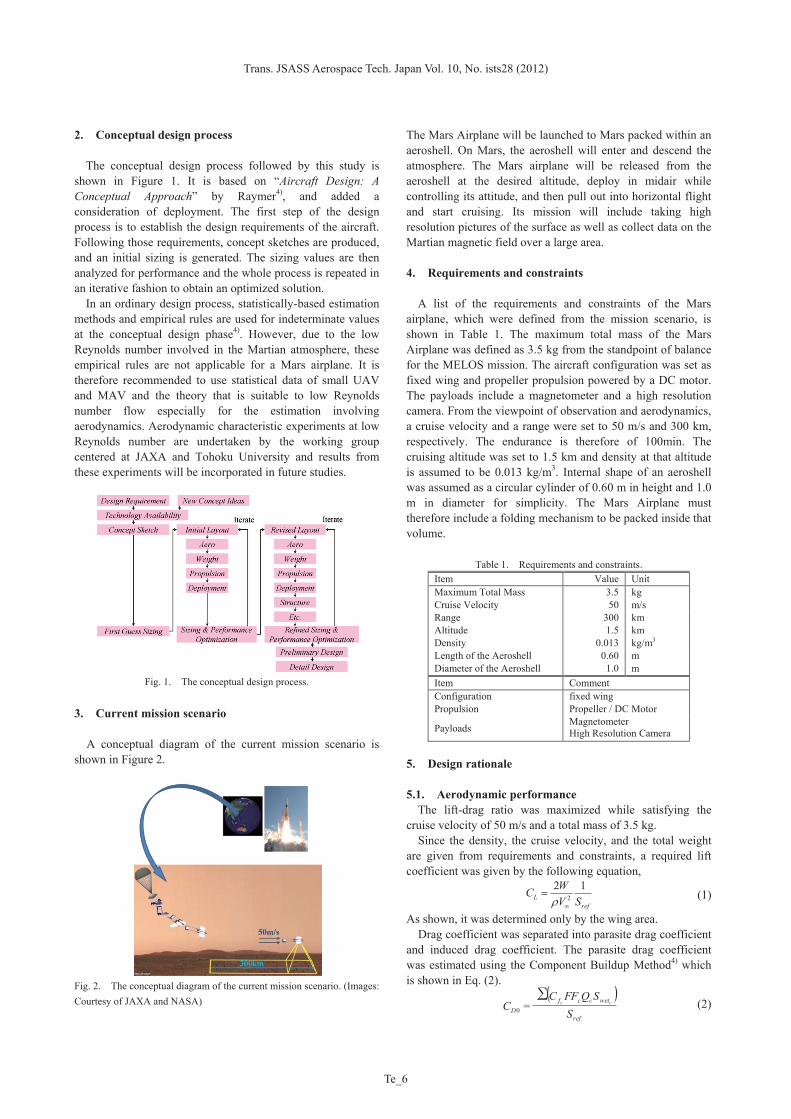
2. Conceptual design process
The conceptual design process followed by this study is shown in Figure 1. It is based on “Aircraft Design: A Conceptual Approach” by Raymer4), and added a consideration of deployment. The first step of the design process is to establish the design requirements of the aircraft. Following those requirements, concept sketches are produced, and an initial sizing is generated. The sizing values are then analyzed for performance and the whole process is repeated in an iterative fashion to obtain an optimized solution.
In an ordinary design process, statistically-based estimation methods and empirical rules are used for indeterminate values at the conceptual design phase4). However, due to the low Reynolds number involved in the Martian atmosphere, these empirical rules are not applicable for a Mars airplane. It is therefore recommended to use statistical data of small UAV and MAV and the theory that is suitable to low Reynolds number flow especially for the estimation involving aerodynamics. Aerodynamic characteristic experiments at low Reynolds number are undertaken by the working group centered at JAXA and Tohoku University and results from these experiments will be incorporated in future studies.
Fig. 1. The conceptual design process.
3. Current mission scenario
A conceptual diagram of the current mission scenario is shown in Figure 2.
Fig. 2. The conceptual diagram of the current mission scenario. (Images: Courtesy of JAXA and NASA)
The Mars Airplane will be launched to Mars packed within an aeroshell. On Mars, the aeroshell will enter and descend the atmosphere. The Mars airplane will be released from the aeroshell at the desired altitude, deploy in midair while controlling its attitude, and then pull out into horizontal flight and start cruising. Its mission will include taking high resolution pictures of the surface as well as collect data on the Martian magnetic field over a large area. 4. Requirements and constraints
A list of the requirements and constraints of the Mars airplane, which were defined from the mission scenario, is shown in Table 1. The maximum total mass of the Mars Airplane was defined as 3.5 kg from the standpoint of balance for the MELOS mission. The aircraft configuration was set as fixed wing and propeller propulsion powered by a DC motor. The payloads include a magnetometer and a high resolution camera. From the viewpoint of observation and aerodynamics, a cruise velocity and a range were set to 50 m/s and 300 km, respectively. The endurance is therefore of 100min. The cruising altitude was set to 1.5 km and density at that altitude is assumed to be 0.013 kg/m3. Internal shape of an aeroshell was assumed as a circular cylinder of 0.60 m in height and 1.0 m in diameter for simplicity. The Mars Airplane must therefore include a folding mechanism to be packed inside that volume.
Table 1. Requirements and constraints. Item Value Unit Maximum Total Mass 3.5 kg Cruise Velocity 50 m/s Range 300 km Altitude 1.5 km Density 0.013 kg/m3 Length of the Aeroshell 0.60 m Diameter of the Aeroshell 1.0 m Item Comment Configuration fixed wing Propulsion Propeller / DC Motor
Payloads Magnetometer High Resolution Camera
5. Design rationale 5.1. Aerodynamic performance
The lift-drag ratio was maximized while satisfying the cruise velocity of 50 m/s and a total mass of 3.5 kg. Since the density, the cruise velocity, and the total weight are given from requirements and constraints, a required lift coefficient was given by the following equation,
(1)
As shown, it was determined only by the wing area. Drag coefficient was separated into parasite drag coefficient and induced drag coefficient. The parasite drag coefficient was estimated using the Component Buildup Method4) which is shown in Eq. (2).
(2)
refL SV
WC 122
( )ref
wetccfD S
SQFFCC cc∑
=0
K. FUJITA et al.: Conceptual Design of Mars Airplane
Te_7
3
First of all, the friction coefficients, form factors, aerodynamic interference factors, and wetted areas were evaluated for each component such as the main wing, fuselage, and so on. From these, parasite drag coefficients for each component were evaluated. The total parasite drag was then obtained from the sum of those. Friction coefficients were evaluated using Eq. (3).
(3)
Form factors indicate the rate of pressure drag coefficient in the parasite drag coefficient. Form factors of the main wing and the tail wing were obtained using Eq. (4),
(4)
and that of the fuselage was obtained using Eq. (5).
(5)
A wing taper ratio of 0.45 was set for high span efficiency. The fuselage was assumed as a circular cylinder of 800 mm in length and 80 mm in diameter. All aerodynamic interference factors were set to 1. The induced drag coefficient was obtained through Eq. (6).
(6)
The span efficiency was estimated using usual statistically-based estimation method4):
(7) The span efficiency was set to a lower value than usual one calculated by Eq. (7) due to the low wing Reynolds number. The drag coefficient was calculated and then the lift-drag ratio was calculated.
Parameters like the wing area, the aspect ratio, etc. were determined to maximize the lift-drag ratio while satisfying the required lift coefficient to be much lower than the maximum lift coefficient. The impact of aspect ratio on the drag coefficient was found to be lower than regular aircraft, because the parasite drag coefficient is the dominant in the total drag coefficient due to the low Reynolds number. A low aspect ratio was preferred from the viewpoint of packing into the aeroshell, and therefore, the aspect ratio was set to 5.6.
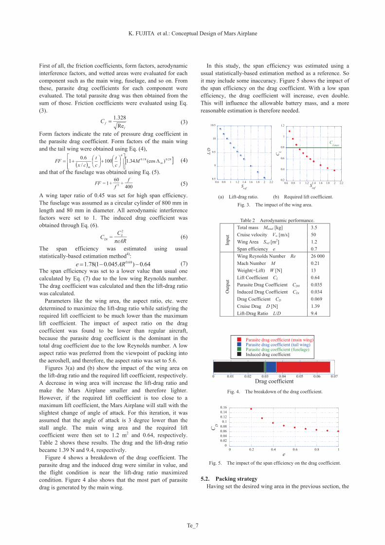
Figures 3(a) and (b) show the impact of the wing area on the lift-drag ratio and the required lift coefficient, respectively. A decrease in wing area will increase the lift-drag ratio and make the Mars Airplane smaller and therefore lighter. However, if the required lift coefficient is too close to a maximum lift coefficient, the Mars Airplane will stall with the slightest change of angle of attack. For this iteration, it was assumed that the angle of attack is 3 degree lower than the stall angle. The main wing area and the required lift coefficient were then set to 1.2 m2 and 0.64, respectively. Table 2 shows these results. The drag and the lift-drag ratio became 1.39 N and 9.4, respectively.
Figure 4 shows a breakdown of the drag coefficient. The parasite drag and the induced drag were similar in value, and the flight condition is near the lift-drag ratio maximized condition. Figure 4 also shows that the most part of parasite drag is generated by the main wing.
In this study, the span efficiency was estimated using a usual statistically-based estimation method as a reference. So it may include some inaccuracy. Figure 5 shows the impact of the span efficiency on the drag coefficient. With a low span efficiency, the drag coefficient will increase, even double. This will influence the allowable battery mass, and a more reasonable estimation is therefore needed.
8.5
9
9.5
10
10.5
0.6 0.8 1 1.2 1.4 1.6 1.8 2 2.2
L/D
Sref
0.2
0.4
0.6
0.8
1
1.2
0.6 0.8 1 1.2 1.4 1.6 1.8 2 2.2
CL
Sref
CLmax
(a) Lift-drag ratio. (b) Required lift coefficient.
Fig. 3. The impact of the wing area.
Table 2 Aerodynamic performance. In
put
Total mass Mtotal [kg] 3.5 Cruise velocity V∞ [m/s] 50 Wing Area Sref [m2] 1.2 Span efficiency e 0.7
Out
put
Wing Reynolds Number Re 26 000 Mach Number M 0.21 Weight(=Lift) W [N] 13 Lift Coefficient CL 0.64 Parasite Drag Coefficient CD0 0.035 Induced Drag Coefficient CDi 0.034 Drag Coefficient CD 0.069 Cruise Drag D [N] 1.39 Lift-Drag Ratio L/D 9.4
0 0.01 0.02 0.03 0.04 0.05 0.06 0.07
Parasite drag coefficient (main wing)Parasite drag coefficient (tail wing)Parasite drag coefficient (fuselage)Induced drag coefficient
Drag coefficient Fig. 4. The breakdown of the drag coefficient.
00.020.040.060.080.1
0.120.140.16
0 0.2 0.4 0.6 0.8 1
CD
e Fig. 5. The impact of the span efficiency on the drag coefficient.
5.2. Packing strategy Having set the desired wing area in the previous section, the
lfC
Re328.1
28.018.04
)(cos34.1100/
6.01 mm
Mct
ct
cxFF
400+
60+1= 3
ff
FF
eARπC
C LDi
2
=
64.0)045.01(78.1 68.0 ARe

Trans. JSASS Aerospace Tech. Japan Vol. 10, No. ists28 (2012)
Te_8
4
packing strategy inside the aeroshell is now discussed. As a starting point, a rectangular wing was assumed for simplicity.
A folding method using hinges was adopted as the deployment mechanism, since it was adopted in many other previous studies2,3) and offers high reliability due to its simple structure.
The position and number of hinges were then considered. Figure 6 shows a sketch of the aeroshell and the main wing in planform. A square can get the maximum area of 0.5 m2 inside the circle of the aeroshell. With the area of the main wing set to 1.2 m2, it is sufficient to separate the main wing into three parts using two hinge lines. A conclusive planform with a tapered geometry was obtained to fit into the aeroshell.
Fig. 6. Sketch of the aeroshell and of the main wing in planform.
5.3. Propulsion performance
The flow around propeller is at low Reynolds number and relatively high Mach number making the propulsion performance estimation quite difficult. In this study, the rate of climb capability was defined as a measure of the propulsion performance. The rate of climb of commercial single engine propeller airplanes at sea-level is required to be at least 4 m/s5). The rate of climb of the Mars Airplane was designed to satisfying this requirement at an altitude of 1.5 km.
The required axial power was evaluated using Eq. (8),
(8)
where the propeller efficiency was set to 0.7. An off-the-shelf motor was selected and its available power was evaluated using Eq. (9).
(9) The available thrust was then evaluated as
(10)
With these values, the rate of climb was then obtained using Eq. (11).
(11)
The impact of the motor power and the propeller efficiency on the rate of climb is shown in Figure 7.
The motor SII-2215-1127KV(V2) manufactured by Scorpion Power System LTD was selected while considering a possibility of decreased propeller efficiency due to low Reynolds number6). This motor could theoretically provide the required rate of climb with its power output of 210 W, while being relatively light with a mass of 69 g. It has slightly higher
power output as a margin for inaccuracy of this elementary estimation. These results are shown in Table 3. A rate of climb of 6.0 m/s was calculated. The rate of climb is reduced to 1.5 m/s at an altitude of 15 km, giving the Mars Airplane a high ceiling altitude. These values require refinement using experimental propeller performance data at the given Reynolds number and Mach number.
0
2
4
6
8
10
12
14
100 150 200 250
prop
=0.6
prop
=0.7
prop
=0.8
prop
=0.9
Rat
e of
Clim
b [m
/s]
P motor
[W]
Fig. 7. The impact of the motor power and the propeller efficiency on the rate of climb.
Table 3 Propulsion performance.
Inpu
t
Cruise Velocity V∞ [m/s] 50 Cruise Drag D [N] 1.39 Propeller Efficiency ηprop 0.7 Motor Output Pmotor [W] 210
Out
put
Cruise Thrust Treq [N] 1.39 Required Axial Power Preq [W] 99 Available Power Pav. [W] 147 Available Thrust Tav. [N] 2.9 Rate of Climb RoC [m/s] 6.0 Altitude at RoC = 1.5m/s [km] 15
5.3. Mass estimation
The total mass was estimated as the sum of the mass of each section. The result is shown in table 4.
For the wing, a frame structure was adopted and its material was set to duralumin. The mass of the wing was obtained by assuming that the mass is proportional to the wing area with 348 g per 1 m2.
Material of fuselage was set to CFRP with a density of 1570 kg/m3. The mass of the fuselage was then calculated by assuming a skin thickness of 0.4 mm.
A two bladed single propeller configuration was assumed. The mass of propeller blade was set to 65 g.
The required mass of battery was estimated using Eq. (12).
(12)
As for the battery, a laminated Li-ion battery was selected. Its energy density was set to 107 Wh/kg. The total required power was calculated as the sum of input power for the motor, payloads, and electronic devices. The power required for the motor was obtained from the propulsion performance calculations described above. From Eq. (12), a partial derivative of the mass of the battery with respect to the drag coefficient was obtained as shown in Eq. (13).
(13)
prop
reqreq
VTP
∞
propmotorav PP .
∞
.. =
VP
T avav
∞
.= VW
DTRoC av-
energy
totalreqbat
EPM
.
gESVC
M
energypropmotorD
battery 43∞ 100.3
2∂
∂
K. FUJITA et al.: Conceptual Design of Mars Airplane
Te_9
5
This shows that the mass of the battery will increase 30 g as a 0.001 increase of the drag coefficient. More accurate drag estimation is therefore needed.
The masses of the magnetometer and the high resolution camera were set to 100 g7), respectively. Including the accessories, the total mass of payloads was set to 550 g.
The masses of the receiver and the navigation system were set to 10 g8) and 400 g, respectively. Four servos were used and their total mass was set to 164 g9). The mass of the wiring was estimated to 20 g.
Table 4 Mass. Main Wing 418 g Fuselage 139 g Tail Wing 142 g Propulsion 219 g Battery 1480 g Payload 550 g Electronic Devices 594 g
Total 3.5 kg 6. Proposed design and its evaluation
Several Mars Airplane configurations were studied in this conceptual design. Two different configurations of the Mars Airplane are presented in this paper. While possessing very different features, they both fulfill the geometrical requirements set in the previous section, which shows the variety of the possibilities of the design. 6.1. Tractor configuration Mars Airplane
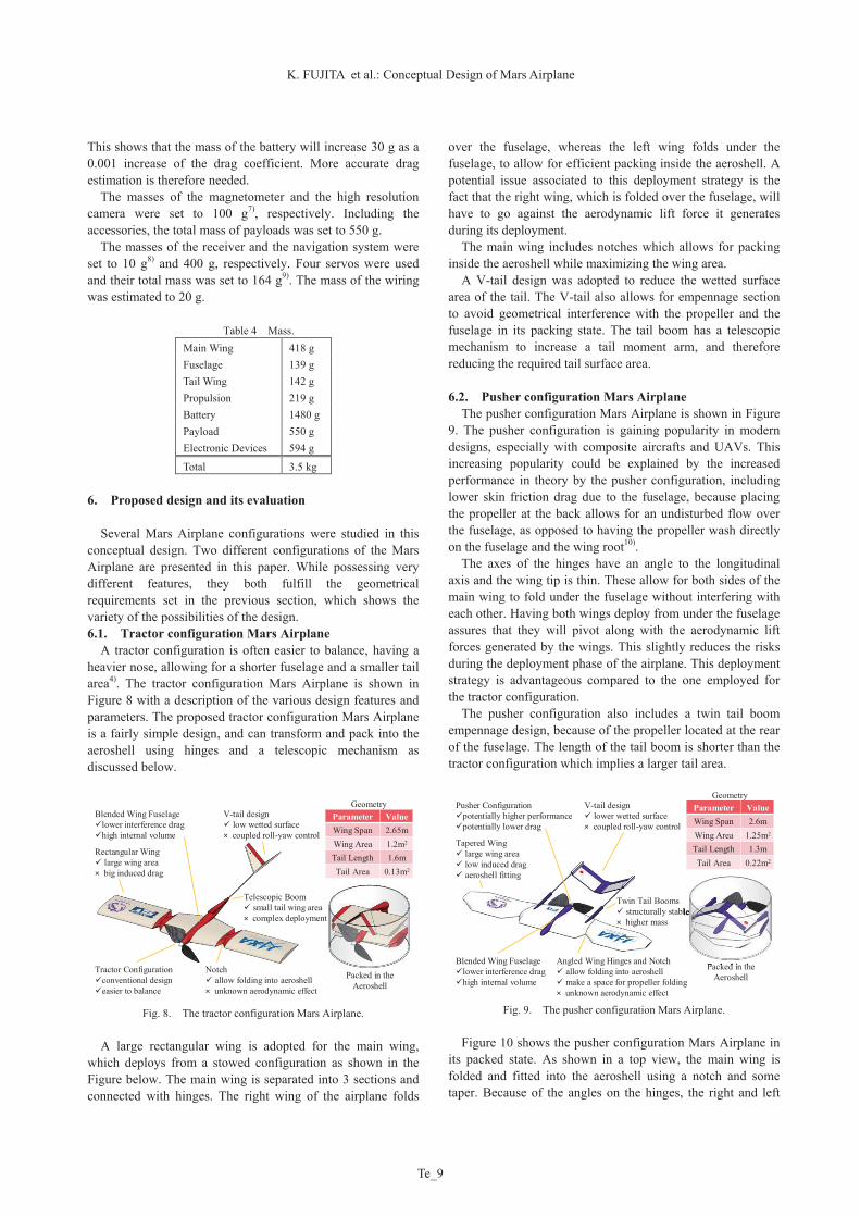
A tractor configuration is often easier to balance, having a heavier nose, allowing for a shorter fuselage and a smaller tail area4). The tractor configuration Mars Airplane is shown in Figure 8 with a description of the various design features and parameters. The proposed tractor configuration Mars Airplane is a fairly simple design, and can transform and pack into the aeroshell using hinges and a telescopic mechanism as discussed below.
Fig. 8. The tractor configuration Mars Airplane.
A large rectangular wing is adopted for the main wing,
which deploys from a stowed configuration as shown in the Figure below. The main wing is separated into 3 sections and connected with hinges. The right wing of the airplane folds
over the fuselage, whereas the left wing folds under the fuselage, to allow for efficient packing inside the aeroshell. A potential issue associated to this deployment strategy is the fact that the right wing, which is folded over the fuselage, will have to go against the aerodynamic lift force it generates during its deployment.
The main wing includes notches which allows for packing inside the aeroshell while maximizing the wing area.
A V-tail design was adopted to reduce the wetted surface area of the tail. The V-tail also allows for empennage section to avoid geometrical interference with the propeller and the fuselage in its packing state. The tail boom has a telescopic mechanism to increase a tail moment arm, and therefore reducing the required tail surface area.
6.2. Pusher configuration Mars Airplane
The pusher configuration Mars Airplane is shown in Figure 9. The pusher configuration is gaining popularity in modern designs, especially with composite aircrafts and UAVs. This increasing popularity could be explained by the increased performance in theory by the pusher configuration, including lower skin friction drag due to the fuselage, because placing the propeller at the back allows for an undisturbed flow over the fuselage, as opposed to having the propeller wash directly on the fuselage and the wing root10).
The axes of the hinges have an angle to the longitudinal axis and the wing tip is thin. These allow for both sides of the main wing to fold under the fuselage without interfering with each other. Having both wings deploy from under the fuselage assures that they will pivot along with the aerodynamic lift forces generated by the wings. This slightly reduces the risks during the deployment phase of the airplane. This deployment strategy is advantageous compared to the one employed for the tractor configuration.
The pusher configuration also includes a twin tail boom empennage design, because of the propeller located at the rear of the fuselage. The length of the tail boom is shorter than the tractor configuration which implies a larger tail area.
Fig. 9. The pusher configuration Mars Airplane.
Figure 10 shows the pusher configuration Mars Airplane in
its packed state. As shown in a top view, the main wing is folded and fitted into the aeroshell using a notch and some taper. Because of the angles on the hinges, the right and left
Rectangular Wing large wing area× big induced drag
Tractor Configurationconventional designeasier to balance
Notch allow folding into aeroshell× unknown aerodynamic effect
Packed in the Aeroshell
V-tail design low wetted surface× coupled roll-yaw control
Blended Wing Fuselagelower interference draghigh internal volume
Parameter ValueWing Span 2.65mWing Area 1.2m2
Tail Length 1.6mTail Area 0.13m2
Parameter ValueWing Span 2.65mWing Area 1.2m2
Tail Length 1.6mTail Area 0.13m2
Geometry
Telescopic Boom small tail wing area× complex deployment
Tapered Wing large wing area low induced drag aeroshell fitting
Pusher Configurationpotentially higher performancepotentially lower drag
Twin Tail Booms structurally stable× higher mass
Angled Wing Hinges and Notch allow folding into aeroshell make a space for propeller folding× unknown aerodynamic effect
Packed in the Aeroshell
V-tail design lower wetted surface× coupled roll-yaw control
Blended Wing Fuselagelower interference draghigh internal volume
Parameter ValueWing Span 2.6mWing Area 1.25m2
Tail Length 1.3mTail Area 0.22m2
Parameter ValueWing Span 2.6mWing Area 1.25m2
Tail Length 1.3mTail Area 0.22m2
Geometry
structurally stable
Packed in the
Trans. JSASS Aerospace Tech. Japan Vol. 10, No. ists28 (2012)
Te_10
6
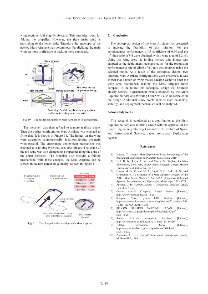
wing sections fold slightly forward. This provides room for folding the propeller. However, the right main wing is protruding to the lower side. Therefore the envelope of the packed Mars Airplane was voluminous. Parallelizing the main wing sections is effective in packing more compactly.
Fig. 10. The pusher configuration Mars Airplane in its packed state.
The aeroshell was then refined to a more realistic shape.
Then the pusher configuration Mars Airplane was changed to fit to that. It is shown in Figure 11. The hinges on the wing were assembled asymmetrically. It allows folding the main wing parallel. The empennage deployment mechanism was changed to a folding type that uses four hinges. The shape of the tail wing was also changed to a trapezoid along the cone of the upper aeroshell. The propeller also includes a folding mechanism. With these changes, the Mars Airplane can be stowed in the new aeroshell geometry, as seen in Figure 11.
Fig. 11. The changed pusher configuration Mars Airplane.
7. Conclusion
The conceptual design of the Mars Airplane was presented to indicate the feasibility of this mission. For the aerodynamics performance, a lift coefficient of 0.64 and the lift-drag ratio of 9.4 were obtained, with a wing area of 1.2 m2. Using this wing area, the folding method with hinges was adopted as the deployment mechanism. As for the propulsion performance, a rate of climb of 6.0 m/s was obtained using the selected motor. As a result of the conceptual design, two different Mars Airplane configurations were presented. It was shown that a notch on wing makes packing easier to keep the wing area maximized, making the Mars Airplane more compact. In the future, this conceptual design will be more closely refined. Experimental results obtained by the Mars Exploration Airplane Working Group will also be reflected in the design. Additional study points such as mass balancing, stability, and deployment mechanism will be analyzed.
Acknowledgments
This research is conducted as a contribution to the Mars Exploration Airplane Working Group with the approval of the Space Engineering Steering Committee of Institute of Space and Astronautical Science, Japan Aerospace Exploration Agency.
References
1) Kubota, T.: Japan’s Mars Exploration Plan, Proceedings of the 2nd Annual Symposium on Planetary Exploration, 2010.
2) Hall, D. W., Parks, R. W., and Morris, S.: Airplane for Mars Exploration, Tech. rep., NASA Ames Research Center, Moffett Federal Airfield, California, 1997.
3) Guynn, M. D., Croom, M. A., Smith, S. C., Parks, R. W., and Gelhausen, P. A.: Evolution of a Mars Airplane Concept for the ARES Mars Scout Mission”, 2nd AIAA Unmanned Unlimited Systems, Technologies, and Operations, AIAA paper 2003-6578.
4) Raymer, D. P.: Aircraft Design: A Conceptual Approach, AIAA Education Series.
5) Cessna Aircraft Company, Single Engine [Internet], http://www.cessna.com/[2011-2-25].
6) Scorpion Power System LTD, Motors, [Internet], http://www.scorpionsystem.com/catalog/motors/s22_series_v2/SII-2215-1127KV/ [2011/4/20].
7) SILICON SENSING SYSTEMS JAPAN, [Internet], http://www.sssj.co.jp/products/applied/pdf/hmr230.pdf [2011-2-25].
8) Sanwa electronic instrument, Receiver, [Internet], http://www.sanwa-denshi.co.jp/rx-01.html [2011/4/20].
9) Futaba Corporation, Servo, [Internet], http://www.rc.futaba.co.jp/servo/products/s3010.html [2011/4/20].
10) Anderson, J. D. Jr.: Aircraft Performance and Design, Boston, McGraw-Hill, 1999.
Asymmetrically ssembled Hinges allow to fold the wing parallel Packed in the
Aeroshell
Trapezoidal Tail fit to the aeroshell
Parameter ValueWing Span 2.6mWing Area 1.25m2
Tail Length 1.3mTail Area 0.21m2
Parameter ValueWing Span 2.6mWing Area 1.25m2
Tail Length 1.3mTail Area 0.21m2
GeometryFoldable Propeller compact× complex
Foldable Tail Booms simple