Compact 3D Coordinate Measuring Machine - …...TOKYO SEIMITSU NEW Compact 3D Coordinate Measuring...
16
TOKYO SEIMITSU NEW Compact 3D Coordinate Measuring Machine Smallest installation area in its class. Compact design for any installation location. XYZAX mju NEX ENGLISH
Transcript of Compact 3D Coordinate Measuring Machine - …...TOKYO SEIMITSU NEW Compact 3D Coordinate Measuring...
TOKYO SEIMITSU
NEW
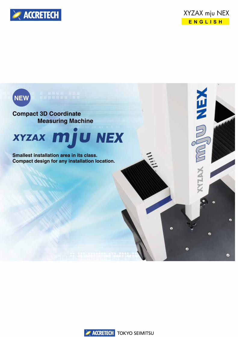
Compact 3D Coordinate Measuring Machine
Smallest installation area in its class.Compact design for any installation location.
XYZAX mju NEXE N G L I S H
2TOKYO SEIMITSU
Hybrid Guideway Technology
03
0201
04
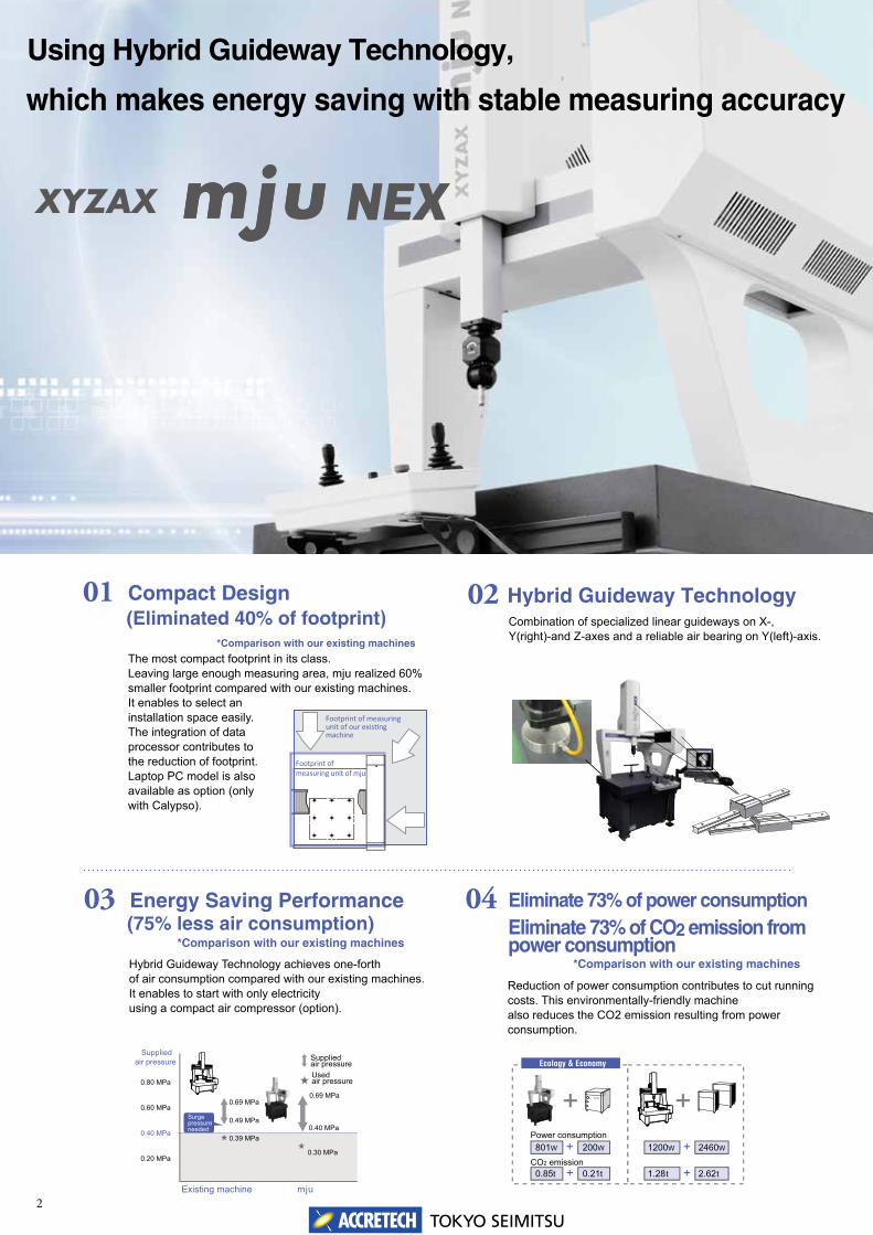
Compact Design
Using Hybrid Guideway Technology,
which makes energy saving with stable measuring accuracy
Existing machine mju
0.69 MPa0.69 MPa
0.40 MPa0.49 MPa
0.39 MPa
0.80 MPa
0.60 MPa
0.40 MPa
0.20 MPa0.30 MPa
Supplied air pressure Supplied
air pressureUsed air pressure
Surge pressureneeded
(Eliminated 40% of footprint)*Comparison with our existing machines
Combination of specialized linear guideways on X-, Y(right)-and Z-axes and a reliable air bearing on Y(left)-axis.
Energy Saving Performance(75% less air consumption)
Hybrid Guideway Technology achieves one-forth of air consumption compared with our existing machines. It enables to start with only electricityusing a compact air compressor (option).
Eliminate 73% of power consumptionEliminate 73% of CO2 emission from power consumption
Reduction of power consumption contributes to cut running costs. This environmentally-friendly machine also reduces the CO2 emission resulting from power consumption.
The most compact footprint in its class.Leaving large enough measuring area, mju realized 60% smaller footprint compared with our existing machines. It enables to select an installation space easily. The integration of data processor contributes to the reduction of footprint. Laptop PC model is also available as option (only with Calypso).
*Comparison with our existing machines
*Comparison with our existing machines
801W +CO2 emission
Power consumption
Ecology & Economy
200W
0.85t + 0.21t
1200W + 2460W
1.28t + 2.62t
Footprint of measuring unit of mju
Footprint of measuring unit of our exis�ng machine
3TOKYO SEIMITSU
Using Hybrid Guideway Technology,
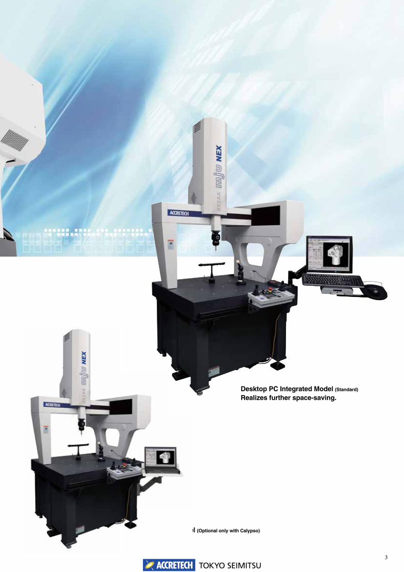
Desktop PC Integrated Model (Standard)
Realizes further space-saving.
Laptop PC Model (Optional only with Calypso)Laptop PC Model
4TOKYO SEIMITSU
Environment Resistant Design06
07 08
05
Scale
Z cover Room air circulation
Fixing rail
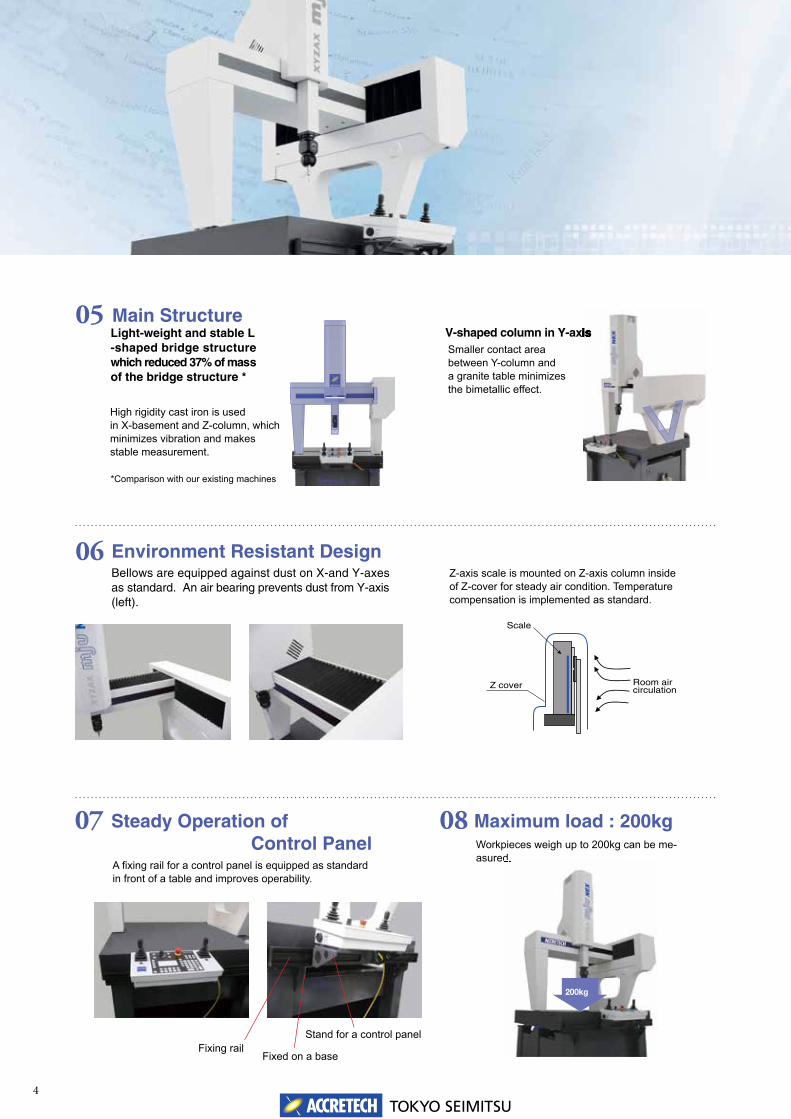
Main StructureLight-weight and stable L-shaped bridge structure which reduced 37% of mass of the bridge structure *
High rigidity cast iron is used in X-basement and Z-column, which minimizes vibration and makes stable measurement.
V-shaped column in Y-axisSmaller contact area between Y-column and a granite table minimizes the bimetallic effect.
Bellows are equipped against dust on X-and Y-axes as standard. An air bearing prevents dust from Y-axis (left).
Z-axis scale is mounted on Z-axis column inside of Z-cover for steady air condition. Temperature compensation is implemented as standard.
Steady Operation of Control PanelA fi xing rail for a control panel is equipped as standard in front of a table and improves operability.
Maximum load : 200kgWorkpieces weigh up to 200kg can be me-asured.
Fixed on a base
Stand for a control panel
*Comparison with our existing machines
asured.
200kg
V-shaped column in Y-axisV-shaped column in Y-axis
5TOKYO SEIMITSU
11
09 10
0.5 mm, mechanical pencil lead
0.3 mm, smallest ball diameter
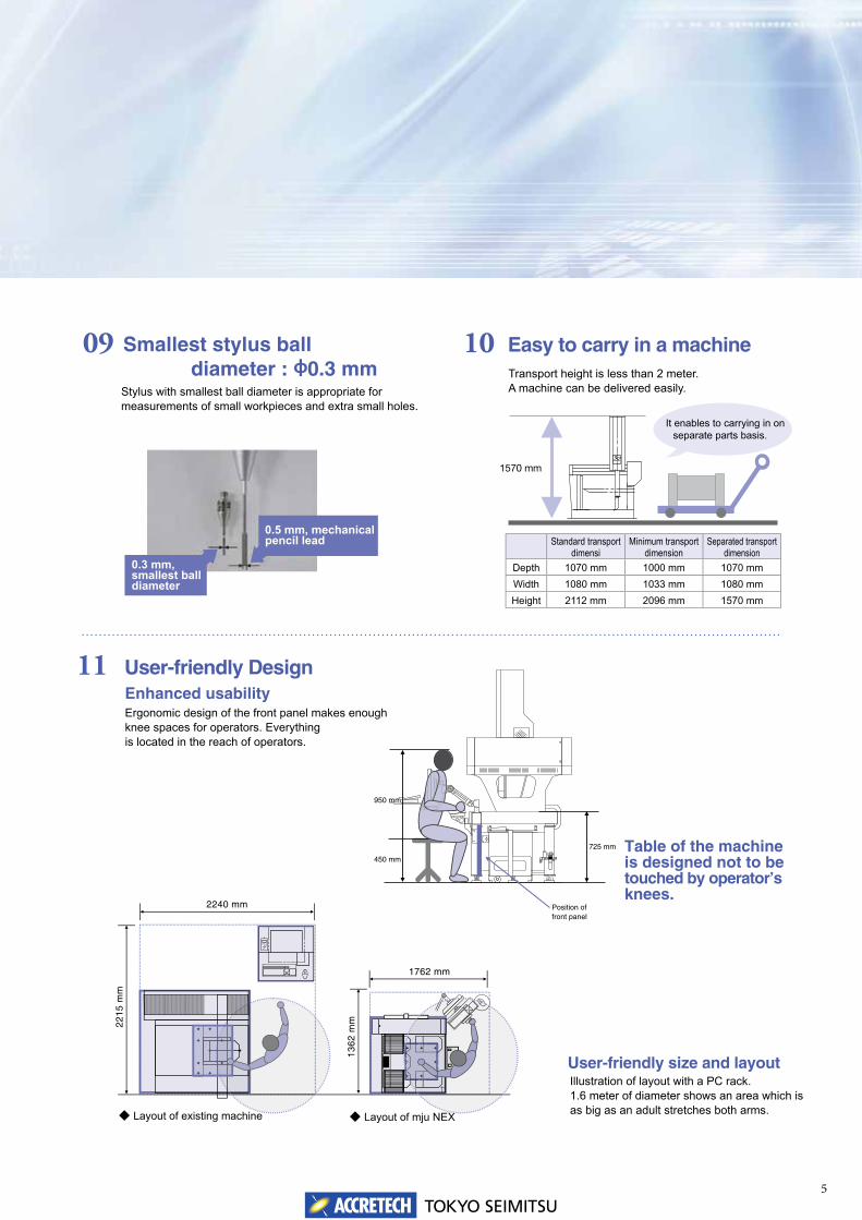
Smallest stylus ball diameter : φ0.3 mmStylus with smallest ball diameter is appropriate for measurements of small workpieces and extra small holes.
Easy to carry in a machineTransport height is less than 2 meter. A machine can be delivered easily.
User-friendly DesignEnhanced usabilityErgonomic design of the front panel makes enough knee spaces for operators. Everything is located in the reach of operators.
Position of front panel
725 mm
450 mm
950 mm
450 mm
950 mm
Table of the machine is designed not to be touched by operator’s knees.
User-friendly size and layoutIllustration of layout with a PC rack.1.6 meter of diameter shows an area which is as big as an adult stretches both arms.◆ Layout of existing machine ◆ Layout of mju NEXLayout of existing machine
13
62
mm
1762 mm
22
15
mm
2240 mm
1570 mm
It enables to carrying in on separate parts basis.
Standard transportdimensi
Minimum transport dimension
Separated transport dimension
Depth 1070 mm 1000 mm 1070 mmWidth 1080 mm 1033 mm 1080 mmHeight 2112 mm 2096 mm 1570 mm
6TOKYO SEIMITSU
■ Option•A4 ink jet printer•Compact wagon for printer•Notebook PC•Stand for notebook PC integrated model with anti-vibration rubber, monitor arm, table for PC•System rack•MCR20 module change rack•Modules•Extensions•Styli•Optional software
►Power supply condition
►Air source condition
*Provide the supplied power before the delivery. To avoid the impact by the power noise, it is recommended to provide one system for the 3D coordinate measuring machine.
*Please prepare power sockets for the machine(mainbody)/PC/monitor/printer
*The maximum value is applied for the above consumption.*Provide an air source and a connection hose before the delivery.*The moisture and the oil content included in the compression air supplied must be removed by using various
devices. Our company can provide recommended various removal device. For more details, contact our branch offices.
Specification
Spec i f i ca t ion
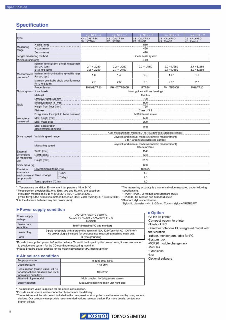
Typemju NEX -□4 mju NEX -□6 mju NEX -□8 mju NEX -□9 mju NEX -□2
C4 : CALYPSOX4 : XYANA
C6 : CALYPSOX6 : XYANA
C8 : CALYPSOX8 : XYANA
C9 : CALYPSOX9 : XYANA
C2 : CALYPSOX2 : XYANA
Measuring range
X-axis (mm) 510Y-axis (mm) 460Z-axis (mm) 410
Length measuring method Linear scale systemMinimum unit (μm) 0.01
Measurement precision *
Maximum permissible error of length meassurementE0, MPE (μm)E150, MPE (μm)
2.7 + L/2503.2 + L/250
2.2 + L/2502.7 + L/150
2.7 + L/150-
2.2 + L/2502.7 + L/150
2.7 + L/2503.2 + L/250
Maximum permissible limit of the repeatability rangeR0, MPL (μm) 1.8 1.4*1 2.0 1.4*1 1.8
Maximum permissible single-stylus form errorPFTU MPE (μm) 2.7 2.5*1 3.3 2.5*1 2.7
Probe System PH10T/TP20 PH10T/TP200B RTP20 PH1/TP200B PH1/TP20Guide system of each axis linear guides with air bearings
Table
Material GabbroEffective width (X) mm 700Effective depth (Y) mm 900Height from floor (mm) 725Flatness Class JIS 1Fixing screw for object to be be measured M10 internal screw
Workpiece measured
Max. height (mm) 520Max. mass (kg) 200
Drive speed
Max. acceleration/deceleration (mm/sec2) 1732
Variable speed rangeAuto measurement mode:0.01 to 433 mm/sec (Stepless control)
Joystick and manual mode (Automatic measurement) 0 to 120 mm/sec (Stepless control)
Measuring speed Joystick and manual mode (Automatic measurement) 0 to 5 mm/sec
External dimensionsof measuring unit
Width (mm) 1145Depth (mm) 1256
Height (mm) 2170
Body mass (kg) 660Precision assurance environmental temp. condi-tion
Environmental temp.(°C) 18 to 22
Temp. change(°C/hr) 1.0(°C/day) 2.0
Temp. gradient (°C/m) 1.0
Power supply voltage
AC100 V / AC110 V ±10 %AC220 V / AC230 V / AC240 V ±10 %
50/60Hz Power con-sumption 801W (including PC and monitor)
Power plug 2-pole receptacle with a grounding terminal:15A, 125V(only for AC 100/110V)No power plug is included for overseas use measuring machine main unit.
Earth D type grounding
Supply pressure 0.40 to 0.69 MPa Used pressure 0.30 MPa Consumption (Status value: 20 °C for atmospheric pressure,and 65 % for relative humidity)
10 NI/min
Attached nipple model High coupler: 1/4"plug (male screw) Supply position Measuring machine main unit right side
*1 Temperature condition: Environment temperature 18 to 24 °C* Measurement precision [E0, MPE, E150, MPE and R0, MPL] are based on
evaluation method of JIS B 7440-2: 2013 (ISO 10360-2: 2009). [PFTU, MPE] is the evaluation method based on JIS B 7440-5:2013(ISO 10360-5:2010)
*L is the distance between any two points (mm).
*The measuring accuracy is a numerical value measured under following specifications.•TP20,RTP20... LFModule and Standard stylus•TP200B...SF Module and Standard stylus
*Standard stylus specification : Stylus tip diameter = φ4, L=20mm, Custom stylus of RENISAW.
7TOKYO SEIMITSU
Dimension
Dimens ion
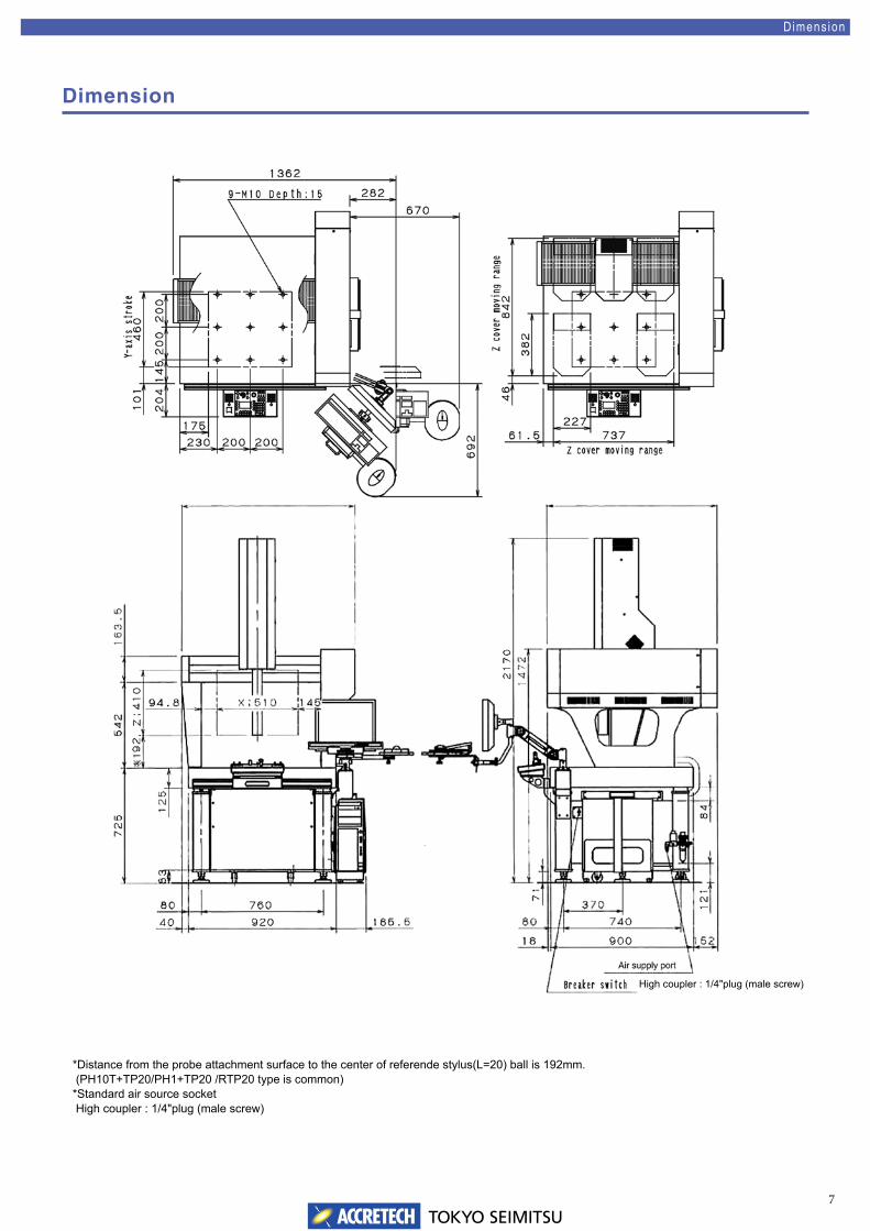
*Distance from the probe attachment surface to the center of referende stylus(L=20) ball is 192mm. (PH10T+TP20/PH1+TP20 /RTP20 type is common) *Standard air source socket High coupler : 1/4"plug (male screw)
High coupler : 1/4"plug (male screw)
8TOKYO SEIMITSU
Probe Sys tem
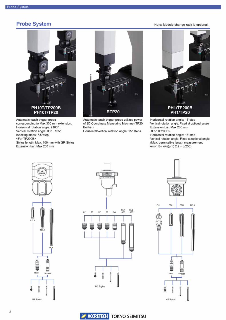
Probe System
Automatic touch trigger probe corresponding to Max.300 mm extension.Horizontal rotation angle: ±180°Vertical rotation angle: 0 to +105°Indexing steps: 7.5°step<For TP200B>Stylus length: Max. 100 mm with GR StylusExtension bar: Max 200 mm
Automatic touch trigger probe utilizes power of 3D Coordinate Measuring Machine (TP20 Built-in)Horizontal/vertical rotation angle: 15° steps
Horizontal rotation angle: 15°stepVertical rotation angle: Fixed at optional angleExtension bar: Max 200 mm<For TP200B>Horizontal rotation angle: 15°stepVertical rotation angle: Fixed at optional angle(Max. permissible length measurement error: E0, MPE(μm) 2.2 + L/250)
Note: Module change rack is optional.
PEL1
PEL2
PL3
TP200BTP20
PEL3
M2 Stylus
M2 Stylus
LF SF MF EF 6W
PK1 PEL1 PEL2
EM1STD
EM2STD
M2 Stylus
TP200BTP20
PH10T/TP200BPH10T/TP20 RTP20
PH1/TP200BPH1/TP20
9TOKYO SEIMITSU
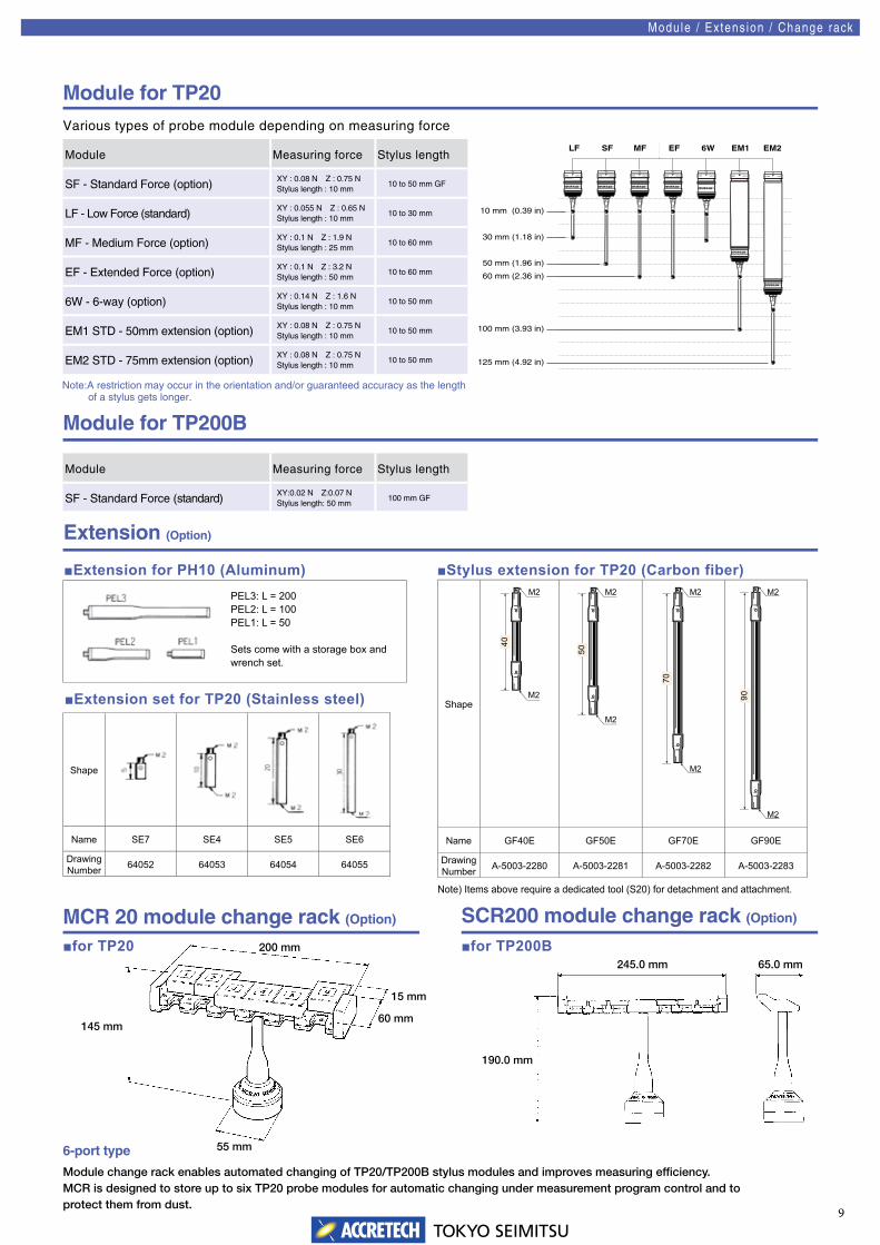
Note:A restriction may occur in the orientation and/or guaranteed accuracy as the length of a stylus gets longer.
10 mm (0.39 in)
125 mm (4.92 in)
100 mm (3.93 in)
60 mm (2.36 in)
50 mm (1.96 in)
30 mm (1.18 in)
LF SF MF EF 6W EM1 EM2
Module for TP20
Modu le / Ex tens ion / Change rack
Various types of probe module depending on measuring force
Extension (Option)
■Extension for PH10 (Aluminum)
■Extension set for TP20 (Stainless steel)
■Stylus extension for TP20 (Carbon fiber)
145 mm
15 mm
60 mm
200 mm
55 mm
245.0 mm 65.0 mm
190.0 mm
MCR 20 module change rack (Option) SCR200 module change rack (Option)
Module change rack enables automated changing of TP20/TP200B stylus modules and improves measuring efficiency.MCR is designed to store up to six TP20 probe modules for automatic changing under measurement program control and toprotect them from dust.
6-port type
■for TP20 ■for TP200B
Shape
Name SE7 SE4 SE5 SE6
DrawingNumber 64052 64053 64054 64055
PEL3: L = 200PEL2: L = 100PEL1: L = 50
Sets come with a storage box and wrench set.
Note) Items above require a dedicated tool (S20) for detachment and attachment.
Shape
Name GF40E GF50E GF70E GF90E
DrawingNumber A-5003-2280 A-5003-2281 A-5003-2282 A-5003-2283
M2
M2
40
M2
M2
50M2
M2
70
M2
M2
90
Module for TP200B
Module Measuring force Stylus length
SF - Standard Force (standard) XY:0.02 N Z:0.07 NStylus length: 50 mm
100 mm GF
Module Measuring force Stylus length
SF - Standard Force (option) XY : 0.08 N Z : 0.75 NStylus length : 10 mm
10 to 50 mm GF
LF - Low Force (standard) XY : 0.055 N Z : 0.65 NStylus length : 10 mm
10 to 30 mm
MF - Medium Force (option) XY : 0.1 N Z : 1.9 NStylus length : 25 mm
10 to 60 mm
EF - Extended Force (option) XY : 0.1 N Z : 3.2 NStylus length : 50 mm
10 to 60 mm
6W - 6-way (option) XY : 0.14 N Z : 1.6 NStylus length : 10 mm
10 to 50 mm
EM1 STD - 50mm extension (option) XY : 0.08 N Z : 0.75 NStylus length : 10 mm
10 to 50 mm
EM2 STD - 75mm extension (option) XY : 0.08 N Z : 0.75 NStylus length : 10 mm
10 to 50 mm
10TOKYO SEIMITSU
A
EWL
C
B
Shape Model Name Drawingnumber
Dimensions (mm) Weight(g)A B C EWL
Shape Model Name Drawingnumber
Dimensions (mm) Weight(g)A B C EWL
Shape Model Name Drawingnumber
Dimensions (mm) Weight(g)A B C EWL
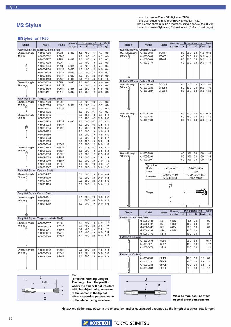
Ruby Ball Stylus (Stainless Steel Shaft)Overall Length:10mm
A-5000-7806A-5000-7802A-5000-7807A-5000-7803A-5000-3604A-5000-4154A-5000-4155A-5000-4156A-5000-4158
PS9RPS24RPS8RPS26RPS1RPS12RPS13RPS14RPS15R
64032
64033
6403464035640366403764038
1.01.52.02.53.04.05.06.08.0
Overall Length:20mm
A-5000-3603A-5000-7804A-5000-4160A-5000-4161
PS2RPS27RPS16RPS17R
64040
6404164042
2.02.53.04.0
Ruby Ball Stylus (Tungsten carbide Shaft)Overall Length:10mm
A-5000-7800A-5000-7805A-5000-7801A-5003-1325
PS29RPS10RPS31R
640310.30.50.71.0
Overall Length:20mm
A-5003-1345A-5003-0577A-5000-7808A-5003-0033A-5003-0034A-5003-3822A-5003-1896A-5003-0938A-5003-1029A-5003-0046
PS23RPS48RPS49R
PS50R
64039
0.50.71.01.01.52.02.53.04.05.0
Overall Length:30mm
A-5000-8663A-5003-0035A-5003-0036A-5003-0038A-5003-0040A-5003-0043A-5003-0047
PS51RPS52RPS53RPS54RPS55RPS56RPS57R
1.01.52.02.53.04.05.0
Ruby Ball Stylus (Ceramic Shaft)
Overall Length:30mm
A-5003-4177A-5003-1370A-5003-4779A-5003-4780
3.04.05.06.0
Ruby Ball Stylus (Carbon Shaft)
Overall Length:30mm
A-5003-4241A-5003-4781A-5003-4782
4.05.06.0
Overall Length:40mm
A-5003-0037A-5003-0039A-5003-0041A-5003-0044A-5003-0048
PS58RPS59RPS60RPS61RPS62R
2.02.53.04.05.0
Overall Length:50mm
A-5003-0042A-5003-0045A-5003-0049
PS63RPS64RPS65R
3.04.05.0
10.010.010.010.010.010.010.010.011.020.020.020.020.0
10.010.010.010.020.020.020.020.020.020.020.020.022.020.027.530.030.030.030.030.030.0
30.030.030.030.0
30.030.030.0
40.040.040.040.040.0
50.050.050.0
0.70.71.01.01.51.52.52.52.51.41.41.51.5
0.20.40.50.70.30.50.70.81.01.01.01.52.02.50.71.01.52.02.02.02.5
2.02.02.52.5
2.03.03.0
1.52.02.02.02.5
2.02.02.5
4.54.56.06.57.0
10.010.010.011.014.016.417.020.0
2.03.04.04.07.0
12.07.0
12.512.514.015.517.022.020.020.522.522.522.527.030.030.0
27.030.030.030.0
30.030.030.0
32.532.537.040.040.0
47.050.050.0
0.30.30.30.30.40.40.70.91.50.40.40.50.6
0.30.30.30.3
0.480.320.500.410.500.480.500.771.241.980.400.580.991.481.491.572.57
0.440.680.931.11
0.570.790.96
1.291.951.972.043.17
2.442.523.75
Ruby Ball Stylus (Ceramic Shaft)Overall Length:50mm
A-5003-0064A-5003-0065A-5003-0066A-5003-0470
PS66RPS67RPS68R
3.04.05.06.0
50.050.050.050.0
2.02.02.52.5
47.050.050.050.0
0.830.911.311.49
Ruby Ball Stylus (Carbon Shaft)Overall Length:50mm
A-5003-2285A-5003-2286A-5003-2287
GF504RGF505RGF506R
4.05.06.0
50.050.050.0
3.03.03.0
50.050.050.0
1.001.101.20
Overall Length:75mm
A-5003-4784A-5003-4785A-5003-4786
4.05.06.0
75.075.075.0
2.03.03.0
75.075.075.0
0.751.351.45
Overall Length:100mm
A-5003-2289A-5003-2290A-5003-2291
4.05.06.0
100.0100.0100.0
3.03.03.0
100.0100.0100.0
1.501.591.78
Extension (Stainless Steel)M-5000-7634M-5000-3647M-5000-3648M-5000-4162M-5000-7779
SE7SE4SE5SE6SE18
64052640536405464055
5.010.020.030.040.0
3.03.03.03.03.0
0.20.40.91.41.8
Extension (Ceramic)
A-5003-0070A-5003-0071A-5003-0072
SE26SE27SE28
30.040.050.0
3.03.03.0
0.971.221.51
Extension (Carbon)
A-5003-2280A-5003-2281A-5003-2282A-5003-2283
GF40EGF50EGF70EGF90E
40.050.070.090.0
3.03.03.03.0
3.53.53.53.5
0.91.01.31.5
Stylus toolModelName
M-5000-3540 A-5003-2300
Remarks For M2 and M3 threaded styli
For M2 carbon fiberstylus series
Shape
S7 S20
DC
B
■Stylus for TP20
Ruby Ball Stylus (Tungsten carbide Shaft)
EWL(Effective Working Length)The length from the positionwhere the axis will not interferewith the object being measuredto the center of the tip ballwhen measuring perpendicularto the object being measured
We also manufacture otherspecial order components.
Sty lus
M2 Stylus
Note:A restriction may occur in the orientation and/or guaranteed accuracy as the length of a stylus gets longer.
It enables to use 50mm GF Stylus for TP20.It enables to use 75mm, 100mm GF Stylus for TP20.The Carbon shaft must be desorption using a special tool (S20).It enables to use Stylus set, Extension set. (Refer to next page)
11TOKYO SEIMITSU
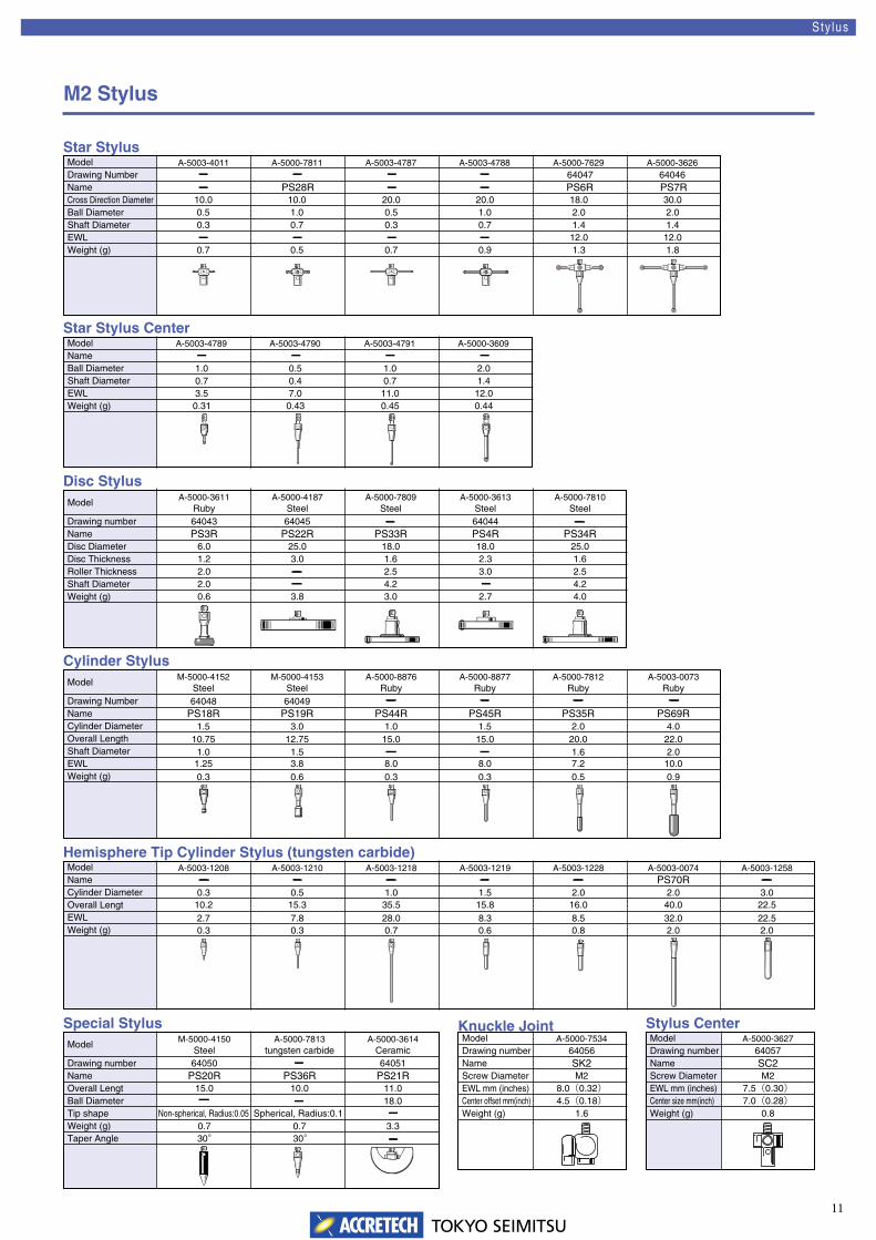
Model A-5003-4011 A-5000-7811 A-5003-4787 A-5003-4788
A-5003-4789 A-5003-4790 A-5003-4791 A-5000-3609
A-5000-7629 A-5000-3626
Name �� � � �
� � �
� � � �
� �PS28R PS6R PS7RCross Direction Diameter
Drawing Number
10.0 10.0 20.0 20.0 18.0 30.0
6404664047
Ball Diameter 0.5 1.0 0.5 1.0 2.0 2.0Shaft Diameter 0.3 0.7 0.3 0.7 1.4 1.4EWL 12.0 12.0Weight (g) 0.7 0.5 0.7 0.9 1.3 1.8
ModelNameBall DiameterShaft DiameterEWLWeight (g) 0.31 0.43 0.45 0.44
ModelA-5000-3611
RubyA-5000-4187
SteelA-5000-7809
SteelA-5000-3613
SteelA-5000-7810
Steel
Name PS3R PS22R PS33R PS4R PS34RDisc Diameter
Drawing number
6.0 25.0 18.0 18.0 25.0
3.0 1.0 1.5 2.0 4.0
64043 64045 64044 �
64048 64049 � � � �
Disc Thickness 1.2 3.0 1.6 2.3 1.6Roller Thickness 2.0 � 2.5 3.0 2.5Shaft Diameter 2.0 � 4.2 4.2Weight (g) 0.6 3.8 3.0 2.7 4.0
ModelM-5000-4152
SteelM-5000-4153
SteelA-5000-8876
RubyA-5000-8877
RubyA-5000-7812
RubyA-5003-0073
A-5003-1208 A-5003-1210 A-5003-1218 A-5003-1219 A-5003-1228 A-5003-0074 A-5003-1258
Ruby
Name PS18R PS19R PS44R PS45R PS35R PS69RCylinder Diameter
Drawing Number
1.512.75 15.0 15.0 20.0 22.010.75
3.8 8.0 8.0 7.2 10.01.250.6 0.3 0.3 0.5 0.90.3
0.5 1.0 1.5 2.0 2.0 3.00.3
0.7 3.30.730° 30°
0.3 0.7 0.6 0.8 2.0 2.00.3
15.3 35.5 15.8 16.0 40.0 22.510.27.8 28.0 8.3 8.5 32.0 22.52.7
1.51.0 2.01.6Overall LengthShaft DiameterEWLWeight (g)
ModelName PS70R�����Cylinder DiameterOverall LengtEWLWeight (g)
ModelM-5000-4150
SteelA-5000-7813
tungsten carbideA-5000-3614
CeramicA-5000-7534
Name PS20R PS36R PS21R
64056
Overall Lengt
Drawing number
15.0
64050 �
�� 18.0
64051
10.0 11.0
SK2
Ball Diameter
M2
Tip shape Non-spherical, Radius:0.05 Spherical, Radius:0.1
8.0(0.32)
Weight (g)
4.5(0.18)
Taper Angle
1.6
Star Stylus
Star Stylus Center
Disc Stylus
Cylinder Stylus
Hemisphere Tip Cylinder Stylus (tungsten carbide)
Special Stylus Knuckle JointModelDrawing numberNameScrew DiameterEWL mm (inches)Center offset mm(inch)Weight (g)
A-5000-362764057SC2M2
7.5(0.30)7.0(0.28)
0.8
Stylus CenterModelDrawing numberNameScrew DiameterEWL mm (inches)Center size mm(inch)Weight (g)
1.0 0.5 1.0 2.00.7 0.4 0.7 1.43.5 7.0 11.0 12.0
Sty lus
M2 Stylus
12TOKYO SEIMITSU
Actual Point Memory
Safety Plane of Probe Path (Generation of CNC measuring plan)
AI Function
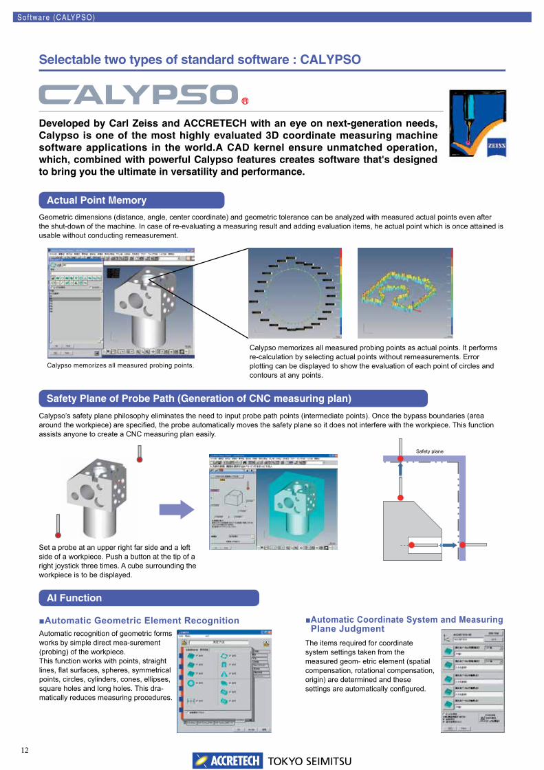
Developed by Carl Zeiss and ACCRETECH with an eye on next-generation needs, Calypso is one of the most highly evaluated 3D coordinate measuring machine software applications in the world.A CAD kernel ensure unmatched operation, which, combined with powerful Calypso features creates software that's designed to bring you the ultimate in versatility and performance.
Sof tware (CALYPSO)
Selectable two types of standard software : CALYPSO
Geometric dimensions (distance, angle, center coordinate) and geometric tolerance can be analyzed with measured actual points even after the shut-down of the machine. In case of re-evaluating a measuring result and adding evaluation items, he actual point which is once attained is usable without conducting remeasurement.
Calypso memorizes all measured probing points.
Calypso memorizes all measured probing points as actual points. It performs re-calculation by selecting actual points without remeasurements. Error plotting can be displayed to show the evaluation of each point of circles and contours at any points.
Calypso’s safety plane philosophy eliminates the need to input probe path points (intermediate points). Once the bypass boundaries (area around the workpiece) are specifi ed, the probe automatically moves the safety plane so it does not interfere with the workpiece. This function assists anyone to create a CNC measuring plan easily.
Set a probe at an upper right far side and a left side of a workpiece. Push a button at the tip of a right joystick three times. A cube surrounding the workpiece is to be displayed.
Safety plane
■Automatic Geometric Element RecognitionAutomatic recognition of geometric forms works by simple direct mea-surement (probing) of the workpiece. This function works with points, straight lines, fl at surfaces, spheres, symmetrical points, circles, cylinders, cones, ellipses, square holes and long holes. This dra-matically reduces measuring procedures.
■ Automatic Coordinate System and Measuring Plane Judgment
The items required for coordinate system settings taken from the measured geom- etric element (spatial compensation, rotational compensation, origin) are determined and these settings are automatically confi gured.
13TOKYO SEIMITSU
On-screen Probe Angle Simulator (Standard)Off-line Teaching Function (Standard)
Automatic Stylus Calibration (Standard) Auto Run Function (Standard)
TESCHART PLUS (Option)Table File Output Program (Option)
Stylus Simulation (Option)
Screw Hole Measuring Program (Option)
List Calibration (Option)Hole Pattern Best Fit (Option)
DMIS Compatible System (Option)
PCM (Parameter Coded Measurement) (Option)
Sof tware (CALYPSO)
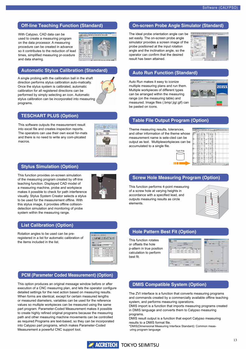
With Calypso, CAD data can be used to create a measuring program on the data processor. A measuring procedure can be created in advance so it contributes to the reduction of lead times, simplifi ed measuring pr-ocedure and data sharing.
The ideal probe orientation angle can be set easily. The on-screen probe angle simulator provides a screen image of the probe positioned at the input rotation angle and the inclination angle, so the operator can confi rm that the desired result has been attained.
A single probing with the calibration ball in the shaft direction performs stylus calibration auto-matically. Once the stylus system is calibrated, automatic calibration for all registered directions can be performed by simply selecting an icon. Automatic stylus calibration can be incorporated into measuring programs.
Auto Run makes it easy to iconize multiple measuring plans and run them.Multiple workpieces of different types can be arranged within the measuring range (on the measuring table) and measured. Image fi les (.bmp/.jig/.gif) can be pasted on icons.
This software outputs the measurement result into excel fi le and creates inspection reports.The operators can use their own excel for-mats and there is no need to write any com-plicated macros.
Theme measuring results, tolerances, and other information of the theme whose measurement name is sele-cted can be output as text. Multipleworkpieces can be accumulated to a single fi le.
This function provides on-screen simulation of the measuring program created by off-line teaching function. Displayed CAD model of a measuring machine, probe and workpiece makes it possible to check for path interference visually. Stylus System Creator selects a stylus to be used for the measurement offl ine. With this stylus image, it provides offl ine collision-detection simulation and monitoring of probe system within the measuring range.
This function performs 4-point measuring of a screw hole at varying heights in accordance with a specifi ed lead, and outputs measuring results as circle elements.
Rotation angles to be used can be pre-registered in a list for automatic calibration of the items included in the list. This function rotates
or offsets the hole p-attern in true position calculation to perform best fi t.
This option produces an original message window before or after execution of a CNC measuring plan, and lets the operator confi gure detailed settings for the next action based on measuring results. When forms are identical, except for certain measured lengths or measured diameters, variables can be used for the reference values so multiple workpieces can be measured using the same part program. Parameter-Coded Measurement makes it possible to create highly refi ned original programs because the measuring path and other measuring machine movements can be controlled as required.Programs are text-based, so they can be incorporated into Calypso part programs, which makes Parameter-Coded Measurement a powerful CNC support tool.
The ZVI interface is a function that converts measuring programs and commands created by a commercially available offl ine teaching system, and performs measuring operations.DMIS import is a function that imports measuring programs created in DMIS language and converts them to Calypso measuring programs.DMIS result output is a function that export Calypso measuring results to a DMIS format fi le.*DMIS(Dimensional Measuring Interface Standard): Common meas- uring program language
Text File

14TOKYO SEIMITSU
ASCII file point data is imported as 2-dimensional curve element design value points. Measuring results also can be saved in an ASCII file as form measuring results.
This program makes it possible to convert IGES or DXF data to anASCII file that can be used as 2-dimension form evaluation designdata, and to convert actual measuring data to IGES or DXF data.
Measuring data from the form measuring program can be evaluated using the TiMS contour analysis software.
Color Graded Comparison View Example Cross Section Evaluation and Part View Example
Surface Normal Direction Error Display Example
Surface Generation Result
Finished Surface ModelSurface Generated Based On Point Groups
HOLOS Light enables instant and simple measuring of simple free-form curved surface, and mea-suring results and measuringpositions can be displayed ins-tantly on the screen.
HOLOS Geo software is for me-asuring standard geometric ele-ments, including holes, referencepoints, etc.
HOLOS Digitize provides speedy and highly accurate reading of a model (unknown free-form curved surface) and generation of the required CAD.
HOLOS enables measuring and comparison measuring of free-formcurved surfaces that include CAD model and other design values. Adding a digitizing function allows digitizing of unknown free-form curved surfaces.
Dimension is software that generates NURBS (Non Uniform Rational Basis Spline) curves and NURBS planes from both 3D point groups and a triangle patch, and from free-form curve and free-form plane surfaces.
HOLOS Extended Extended Free-form Curved Surface Measuring Software
HOLOS Light Basic Free-form Curved Surface Measuring SoftwareCurved Surface Measuring Software
HOLOS Light Free-form Curved Surface Data Generation Software
HOLOS Geo Standard Geometric Element Measuring Software
Sof tware (CALYPSO)
Selectable two types of standard software : CALYPSO■HOLOS : Free-form Curved Surface Measuring Program (Option)
HOLOS Extended can be added on to HOLOS Light when speedy and accurate continuous measuring of complex free-form curved surface is required.
■Dimension NT : Free-form curved surface generation program (Option)
■Blade Pro:Turbine Blade Evaluation Program (Option)There are a number of different parameters and analytical methods used for controlling the quality of turbine blades.Blade Pro is the specialized software for turbine blades evaluations.Blade Pro imports nominal values and actual measured value data and performs turbine blade evaluation.
All text and figures are freely movable, and rotate and move operations are supported.
Multiple figures and text elements can be mixed into a single document.
■Calypso-TiMS Conversion Program (Option)
■IGES/DXF-ASCII Conversion Program (Option)
■Form Data ASCII Input/Output Program (Option)
■Calypso-CURVE : Form Measuring ProgramCalypso-CURVE is a Calypso option program for measuring 2-dimensional cross section forms of a workpiece. This program allows measuring of known/unknown contours and forms, and integrating of design values. Measuring data is output as normal direction error with the design values. When there is a deviation in the error due to shifting of the standard, 2D best fit eliminates any inappropriate error in the measuring standard so the form can be evaluated.
■Cylindrical Cam Measurement Calypso-CURVE measures grooves of both sides of cyli-ndrical cam form. Using the measurement result, the ce-nter of the curve and groove width are calculated and evaluated.
15TOKYO SEIMITSU
1. Freely Arrangeable Icon Menu
2. Three Measuring Modes
3. User Codes
4. Teaching and Auto
5. Versatile Functions for Verifying Design Values
6. Other Major Functions
■ XYANA 2000 Functions
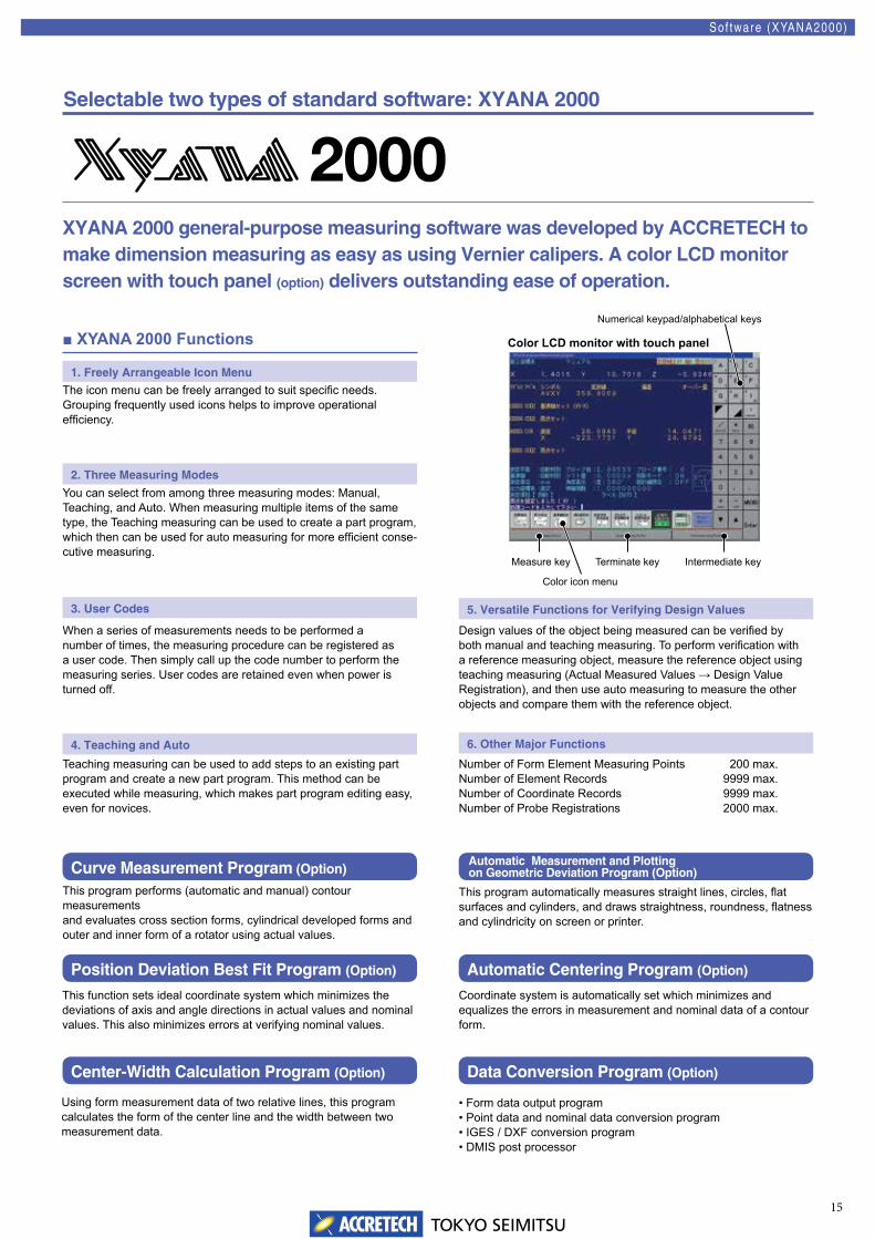
The icon menu can be freely arranged to suit specific needs.Grouping frequently used icons helps to improve operational efficiency.
You can select from among three measuring modes: Manual, Teaching, and Auto. When measuring multiple items of the same type, the Teaching measuring can be used to create a part program, which then can be used for auto measuring for more efficient conse-cutive measuring.
When a series of measurements needs to be performed a number of times, the measuring procedure can be registered as a user code. Then simply call up the code number to perform the measuring series. User codes are retained even when power is turned off.
Teaching measuring can be used to add steps to an existing part program and create a new part program. This method can be executed while measuring, which makes part program editing easy, even for novices.
Design values of the object being measured can be verified by both manual and teaching measuring. To perform verification with a reference measuring object, measure the reference object using teaching measuring (Actual Measured Values → Design Value Registration), and then use auto measuring to measure the other objects and compare them with the reference object.
Number of Form Element Measuring Points Number of Element Records Number of Coordinate Records Number of Probe Registrations
200 max.9999 max.9999 max.2000 max.
XYANA 2000 general-purpose measuring software was developed by ACCRETECH to make dimension measuring as easy as using Vernier calipers. A color LCD monitor screen with touch panel (option) delivers outstanding ease of operation.
Curve Measurement Program (Option)
Position Deviation Best Fit Program (Option)
Center-Width Calculation Program (Option)
Automatic Measurement and Plotting on Geometric Deviation Program (Option)
Automatic Centering Program (Option)
Data Conversion Program (Option)
Sof tware (XYANA2000)
Selectable two types of standard software: XYANA 2000
This program performs (automatic and manual) contour measurements and evaluates cross section forms, cylindrical developed forms and outer and inner form of a rotator using actual values.
This program automatically measures straight lines, circles, flat surfaces and cylinders, and draws straightness, roundness, flatness and cylindricity on screen or printer.
This function sets ideal coordinate system which minimizes the deviations of axis and angle directions in actual values and nominal values. This also minimizes errors at verifying nominal values.
Coordinate system is automatically set which minimizes and equalizes the errors in measurement and nominal data of a contour form.
Using form measurement data of two relative lines, this program calculates the form of the center line and the width between two measurement data.
• Form data output program• Point data and nominal data conversion program• IGES / DXF conversion program• DMIS post processor
Color icon menu
Numerical keypad/alphabetical keys
Measure key Terminate key Intermediate key
Color LCD monitor with touch panel
TOKYO SEIMITSU
B-81-604-E-1507ISO 9001 and ISO 14001 awarded to the Hachioji and Tsuchiura Plants
We reserve the right to change the contents of this catalog, including product specifications, without notice when products are updated.
Some of our products shall be controlled by the Foreign Exchange and Foreign Trade Act,
and required an export license by the Japanese Government.
Regarding exporting the products and/or providing a non-resident with technologies,
please consult ACCRETECH(Tokyo Seimitsu).
h t t p : / / w w w . a c c r e t e c h . j p /
Head Office2968-2, Ishikawa-machi, Hachioji-city, Tokyo 192-0032, JapanTEL: +81(0)42-642-1701 FAX: +81(0)42-642-1821
International Sales and Marketing4, Higashi-Nakanuki-machi,Tsuchiura-city, Ibaraki 300-0006, JapanTEL: +81(0)29-831-1240 FAX: +81(0)29-831-1461
Vietnam / Accretech Vietnam Co., Ltd.Hanoi Representative Office356 room, 6th Floor, Office Building, 85 Nguyen Du St, Hai Ba Trung Dist, Hanoi, Vietnam
TEL: +84(4)3941-3309 FAX: +84-4-3941-3310Ho Chi Minh OfficeRoom No.1101-1102, the 11th Floor, Broadcast Office Building, 343 Dien Bien Phu Street, Ward,15, Binh Thanh District, Ho Chi Minh City, VietnamTEL: +84(8)3512-6760 FAX: +84(4)3941-3310
Brasil / Accretech do Brasil Ltda. 77 Room, 7th Floor, Rua Nove de Julho 72Santo Amaro, Sao Paulo 04739-010, BrazilTEL/FAX: +55(0)11-3360-9531
China / Accretech (China) Co., Ltd. Head Office / ShanghaiRoom2101C, No.1077 ZuChongZhi Road, Zhang Jiang Hi-Tech Park, Pudong New Area,Shanghai, China, 201203TEL: +86(0)21-3887-0801 FAX: +86(0)21-3887-0805
Korea / Accretech Korea Co., Ltd. Head Office / Seongnam(3F, Fine Venture Bldg., Yatap-dong) 41, Seongnam-daero 925 beon-gil, Bundang-gu,Seongnam-si, Gyeonggi-do, 463-828, Korea
TEL: +82(0)31-786-4000 FAX: +82(0)31-786-4090Ulsan Office(1F 841-8, Myeongchon-dong)30, Myeongchon 7-gil, Buk-gu, Ulsan, 683-390, KoreaTEL: +82(0)52-268-2136 FAX: +82(0)52-268-2137
Thailand / Tokyo Seimitsu (Thailand) Co., Ltd. HQ & Metrology2/3 Moo 14, Bangna Tower B, 1st Fl., Bangna-Trad Road. K.M. 6.5, Bangkaew, Bangplee, Samutprakarn 10540, ThailandTEL: +66(2)751-9573, 9574 FAX: +66(2)751-9575
Taiwan / Accretech (Taiwan) Co., Ltd.Metrology Division2F, No.199, Zhonghe St., Zhubei City,Hsinchu County 30267, Taiwan (R.O.C)TEL: +886(0)3-553-1300 FAX: +886(0)3-553-1319
Indonesia / PT Accretech IndonesiaKomplek Rukan Cikarang Square Block D No.68JL. Raya Cikarang-Cibarusah KM 40 No.1 CikarangBekasi 17530, IndonesiaTEL: +62(0)21-2961-2375 FAX: +62(0)21-2961-2376
World wide Sales and Service Offices