90-269-01 MicroStop dt · The miniaturized plate for the ulna and radius shortening allows for a...
16
Hand Surgery URS Mini ULNA- UND RADIUSVERKÜRZUNGSSYSTEM NACH PROF. H. KRIMMER UND DR. M. LEIXNERING ULNA- AND RADIUS SHORTENING SYSTEM ACC. TO PROF. H. KRIMMER AND DR. M. LEIXNERING
Transcript of 90-269-01 MicroStop dt · The miniaturized plate for the ulna and radius shortening allows for a...
Hand Surgery
URS MiniULNA- UND RADIUSVERKÜRZUNGSSYSTEM
NACH PROF. H. KRIMMER UND DR. M. LEIXNERING
ULNA- AND RADIUS SHORTENING SYSTEM
ACC. TO PROF. H. KRIMMER AND DR. M. LEIXNERING
Einleitung
Die ulnare Verkürzungsosteotomie stellt eine aner-kannte Behandlungsmethode bei dem Ulna-Impaction-Syndrom dar. Aufgrund des Weichteilzuges kommt esbeim Schluss des Osteotomiespaltes zu Drehfehlern.Zur Vermeidung dieser Problematik wurde eine neuefiligrane Gleitlochplatte konzipiert, die eine Verkürzungvon bis zu 8 mm ermöglicht.
Aufgrund der proximalen Anordnung von Langlöchernkann die Osteotomie bei liegender Platte erfolgenund die beiden Osteotomiehälften sind rotationsstabil.Neue Sägelehren, die zwischen Platte und Knochensitzen, bieten eine gute Führung für das Sägeblatt.Dadurch wird ein stufenfreier und paralleler Osteo-tomieschnitt ermöglicht. Eine die Schrägosteotomieüberbrückende Zugschraube führt zur Kompressiondes Osteotomiespaltes. Somit verringert sich diePseudarthrosenrate und die Operationstechnik istvereinfacht.
PROF. H. KRIMMER
DR. M. LEIXNERING
Indikation
Impaction-Syndrom der Ulna oder des Radius
Vorteile
Rotationsstabilität durch Plattenanlage vor derOsteotomieNiedrige PseudarthrosenrateNiedrige Profilhöhe (3,2 mm) und Verjüngung derdistalen und proximalen Plattenkante (1,9 mm)Bohrhülsen zur orthogonalen Führung des BohrersStabile Fixierung mit 2,7 mm langen, winkel-stabilen T-Drive-SchraubenVerkürzung um bis zu 8 mmSpezielle Oberflächenbehandlung der Plattenminimiert Ermüdung und Abrieb des MaterialsNeue Sägelehren ermöglichen eine stufenfreieund parallele OsteotomieIntegrierbar im Radiusverplattungssystem (FAROS)→ Unterarmrekonstruktionssystem
•
•
••
••
••
•
•
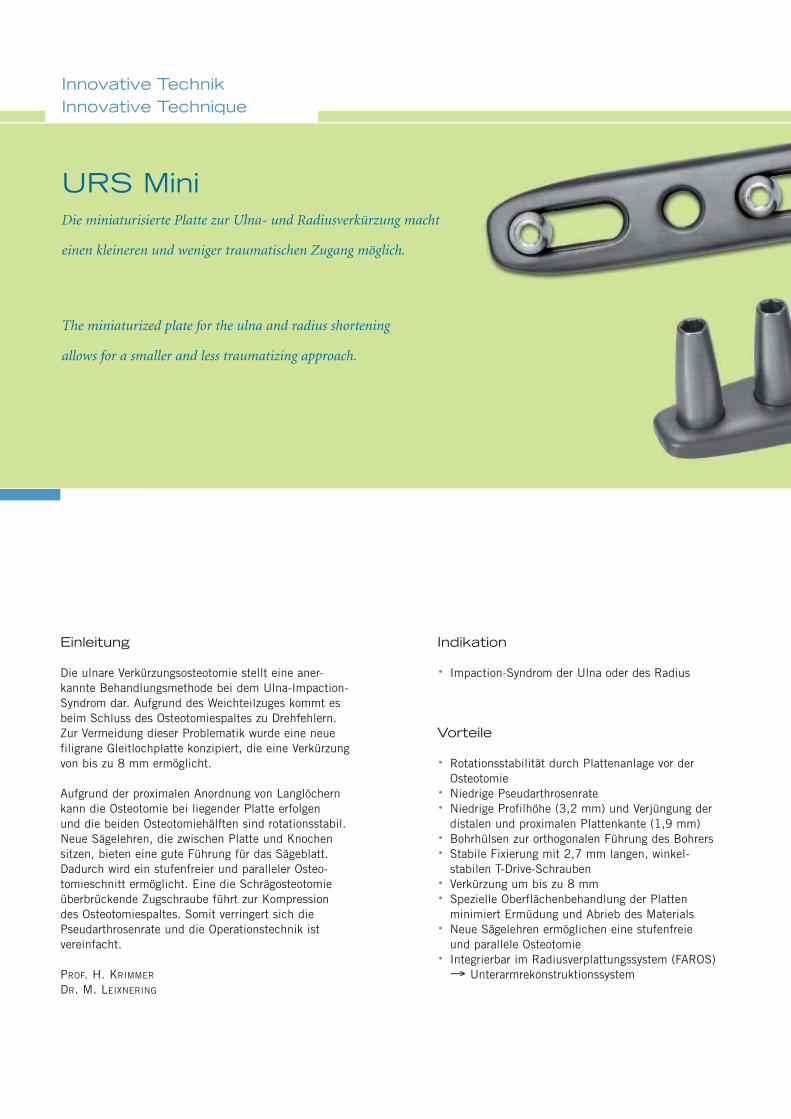
Die miniaturisierte Platte zur Ulna- und Radiusverkürzung macht
einen kleineren und weniger traumatischen Zugang möglich.
URS Mini
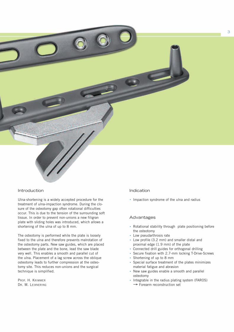
The miniaturized plate for the ulna and radius shortening
allows for a smaller and less traumatizing approach.
Innovative TechnikInnovative Technique
Introduction
Ulna-shortening is a widely accepted procedure for thetreatment of ulna-impaction syndrome. During the clo-sure of the osteotomy gap often rotational difficultiesoccur. This is due to the tension of the surrounding softtissue. In order to prevent non-unions a new filigranplate with sliding holes was introduced, which allows ashortening of the ulna of up to 8 mm.
The osteotomy is performed while the plate is looselyfixed to the ulna and therefore prevents malrotation ofthe osteotomy parts. New saw guides, which are placedbetween the plate and the bone, lead the saw bladevery well. This enables a smooth and parallel cut ofthe ulna. Placement of a lag screw across the obliqueosteotomy leads to further compression at the osteo-tomy site. This reduces non-unions and the surgicaltechnique is simplified.
PROF. H. KRIMMER
DR. M. LEIXNERING
Indication
Impaction syndrome of the ulna and radius
Advantages
Rotational stability through plate positioning beforethe osteotomyLow pseudarthrosis rateLow profile (3.2 mm) and smaller distal andproximal edge (1.9 mm) of the plateConnected drill guides for orthogonal drillingSecure fixation with 2.7-mm locking T-Drive-ScrewsShortening of up to 8 mmSpecial surface treatment of the plates minimizesmaterial fatigue and abrasionNew saw guides enable a smooth and parallelosteotomyIntegrable in the radius plating system (FAROS)→ Forearm reconstruction set
•
•
••
••••
•
•
3
Operationstechnik – UlnaverkürzungSurgical Technique – Ulna-Shortening
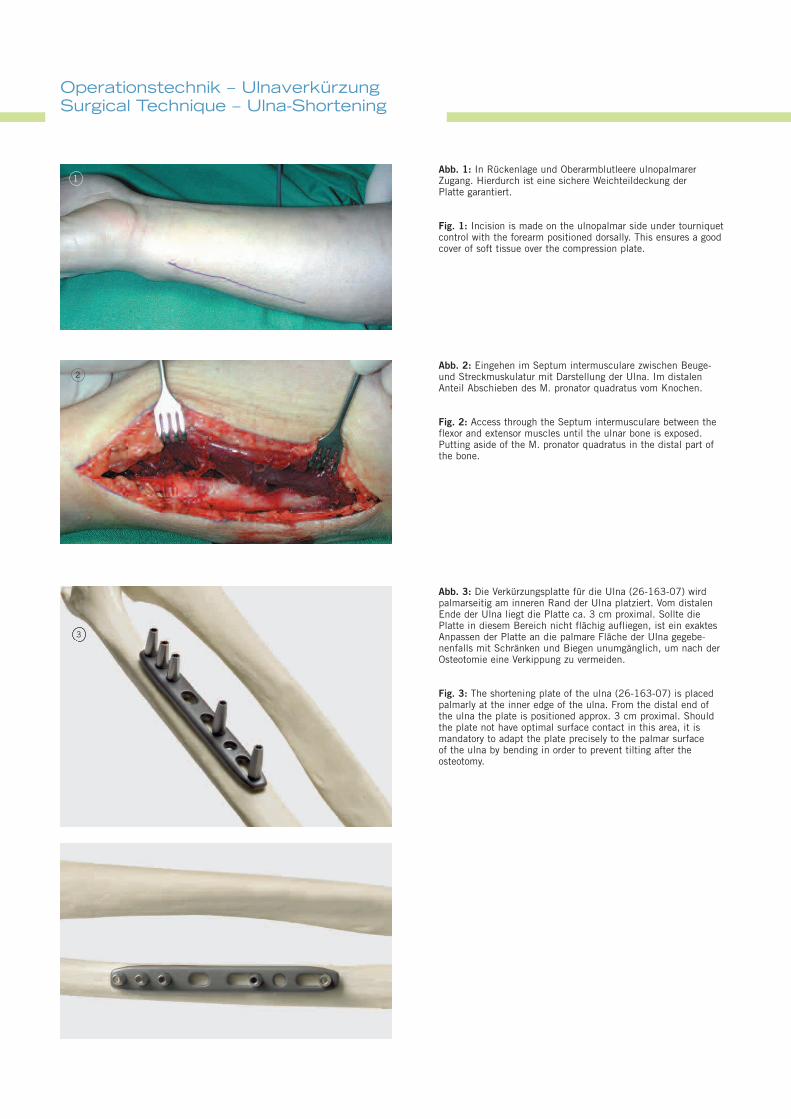
Abb. 1: In Rückenlage und Oberarmblutleere ulnopalmarerZugang. Hierdurch ist eine sichere Weichteildeckung derPlatte garantiert.
Fig. 1: Incision is made on the ulnopalmar side under tourniquetcontrol with the forearm positioned dorsally. This ensures a goodcover of soft tissue over the compression plate.
Abb. 3: Die Verkürzungsplatte für die Ulna (26-163-07) wirdpalmarseitig am inneren Rand der Ulna platziert. Vom distalenEnde der Ulna liegt die Platte ca. 3 cm proximal. Sollte diePlatte in diesem Bereich nicht flächig aufliegen, ist ein exaktesAnpassen der Platte an die palmare Fläche der Ulna gegebe-nenfalls mit Schränken und Biegen unumgänglich, um nach derOsteotomie eine Verkippung zu vermeiden.
Fig. 3: The shortening plate of the ulna (26-163-07) is placedpalmarly at the inner edge of the ulna. From the distal end ofthe ulna the plate is positioned approx. 3 cm proximal. Shouldthe plate not have optimal surface contact in this area, it ismandatory to adapt the plate precisely to the palmar surfaceof the ulna by bending in order to prevent tilting after theosteotomy.
Abb. 2: Eingehen im Septum intermusculare zwischen Beuge-und Streckmuskulatur mit Darstellung der Ulna. Im distalenAnteil Abschieben des M. pronator quadratus vom Knochen.
Fig. 2: Access through the Septum intermusculare between theflexor and extensor muscles until the ulnar bone is exposed.Putting aside of the M. pronator quadratus in the distal part ofthe bone.
1
2
3
55
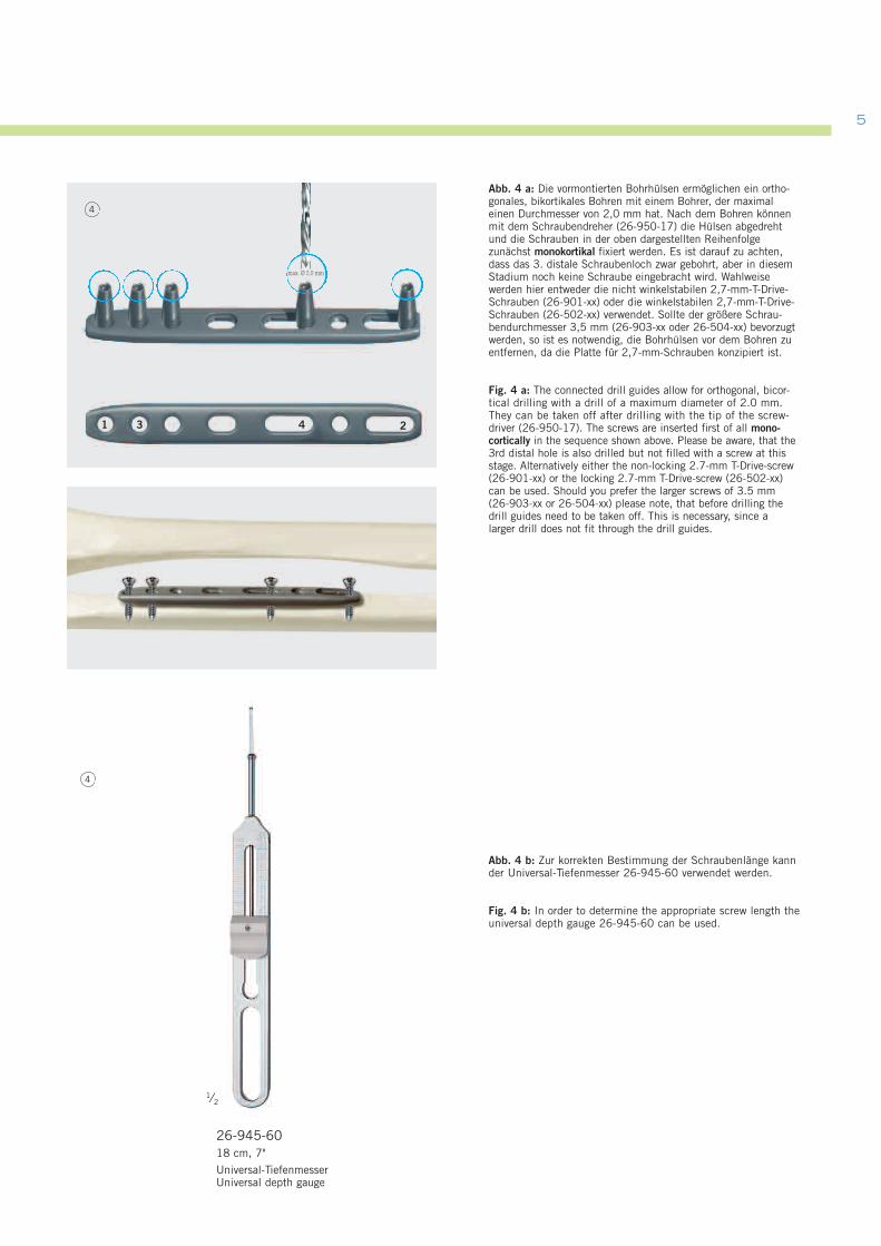
Abb. 4 b: Zur korrekten Bestimmung der Schraubenlänge kannder Universal-Tiefenmesser 26-945-60 verwendet werden.
Fig. 4 b: In order to determine the appropriate screw length theuniversal depth gauge 26-945-60 can be used.
Abb. 4 a: Die vormontierten Bohrhülsen ermöglichen ein ortho-gonales, bikortikales Bohren mit einem Bohrer, der maximaleinen Durchmesser von 2,0 mm hat. Nach dem Bohren könnenmit dem Schraubendreher (26-950-17) die Hülsen abgedrehtund die Schrauben in der oben dargestellten Reihenfolgezunächst monokortikal fixiert werden. Es ist darauf zu achten,dass das 3. distale Schraubenloch zwar gebohrt, aber in diesemStadium noch keine Schraube eingebracht wird. Wahlweisewerden hier entweder die nicht winkelstabilen 2,7-mm-T-Drive-Schrauben (26-901-xx) oder die winkelstabilen 2,7-mm-T-Drive-Schrauben (26-502-xx) verwendet. Sollte der größere Schrau-bendurchmesser 3,5 mm (26-903-xx oder 26-504-xx) bevorzugtwerden, so ist es notwendig, die Bohrhülsen vor dem Bohren zuentfernen, da die Platte für 2,7-mm-Schrauben konzipiert ist.
Fig. 4 a: The connected drill guides allow for orthogonal, bicor-tical drilling with a drill of a maximum diameter of 2.0 mm.They can be taken off after drilling with the tip of the screw-driver (26-950-17). The screws are inserted first of all mono-cortically in the sequence shown above. Please be aware, that the3rd distal hole is also drilled but not filled with a screw at thisstage. Alternatively either the non-locking 2.7-mm T-Drive-screw(26-901-xx) or the locking 2.7-mm T-Drive-screw (26-502-xx)can be used. Should you prefer the larger screws of 3.5 mm(26-903-xx or 26-504-xx) please note, that before drilling thedrill guides need to be taken off. This is necessary, since alarger drill does not fit through the drill guides.
max. Ø 2,0 mm
4
4
1 3 4 2
26-945-6018 cm, 7"
Universal-TiefenmesserUniversal depth gauge
1⁄2
Operationstechnik – UlnaverkürzungSurgical Technique – Ulna-Shortening
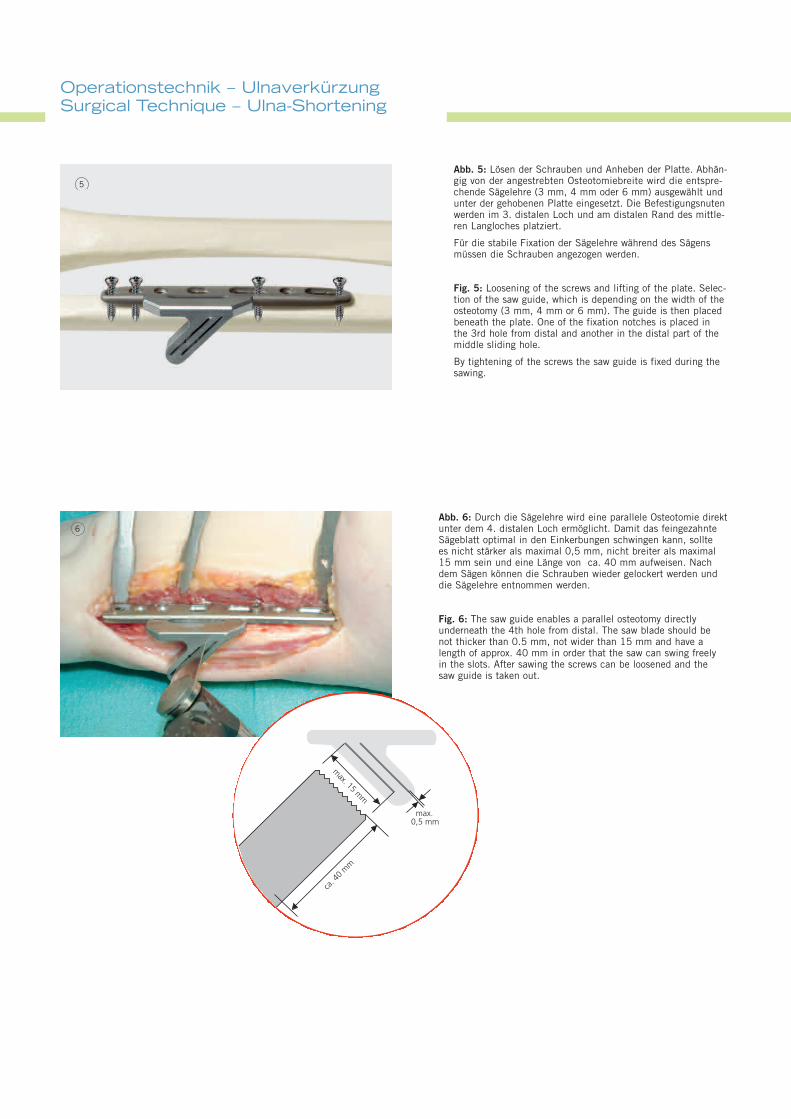
Abb. 6: Durch die Sägelehre wird eine parallele Osteotomie direktunter dem 4. distalen Loch ermöglicht. Damit das feingezahnteSägeblatt optimal in den Einkerbungen schwingen kann, solltees nicht stärker als maximal 0,5 mm, nicht breiter als maximal15 mm sein und eine Länge von ca. 40 mm aufweisen. Nachdem Sägen können die Schrauben wieder gelockert werden unddie Sägelehre entnommen werden.
Fig. 6: The saw guide enables a parallel osteotomy directlyunderneath the 4th hole from distal. The saw blade should benot thicker than 0.5 mm, not wider than 15 mm and have alength of approx. 40 mm in order that the saw can swing freelyin the slots. After sawing the screws can be loosened and thesaw guide is taken out.
6
max. 15
mm
max.0,5 mm
ca. 4
0m
m
Abb. 5: Lösen der Schrauben und Anheben der Platte. Abhän-gig von der angestrebten Osteotomiebreite wird die entspre-chende Sägelehre (3 mm, 4 mm oder 6 mm) ausgewählt undunter der gehobenen Platte eingesetzt. Die Befestigungsnutenwerden im 3. distalen Loch und am distalen Rand des mittle-ren Langloches platziert.
Für die stabile Fixation der Sägelehre während des Sägensmüssen die Schrauben angezogen werden.
Fig. 5: Loosening of the screws and lifting of the plate. Selec-tion of the saw guide, which is depending on the width of theosteotomy (3 mm, 4 mm or 6 mm). The guide is then placedbeneath the plate. One of the fixation notches is placed inthe 3rd hole from distal and another in the distal part of themiddle sliding hole.
By tightening of the screws the saw guide is fixed during thesawing.
5
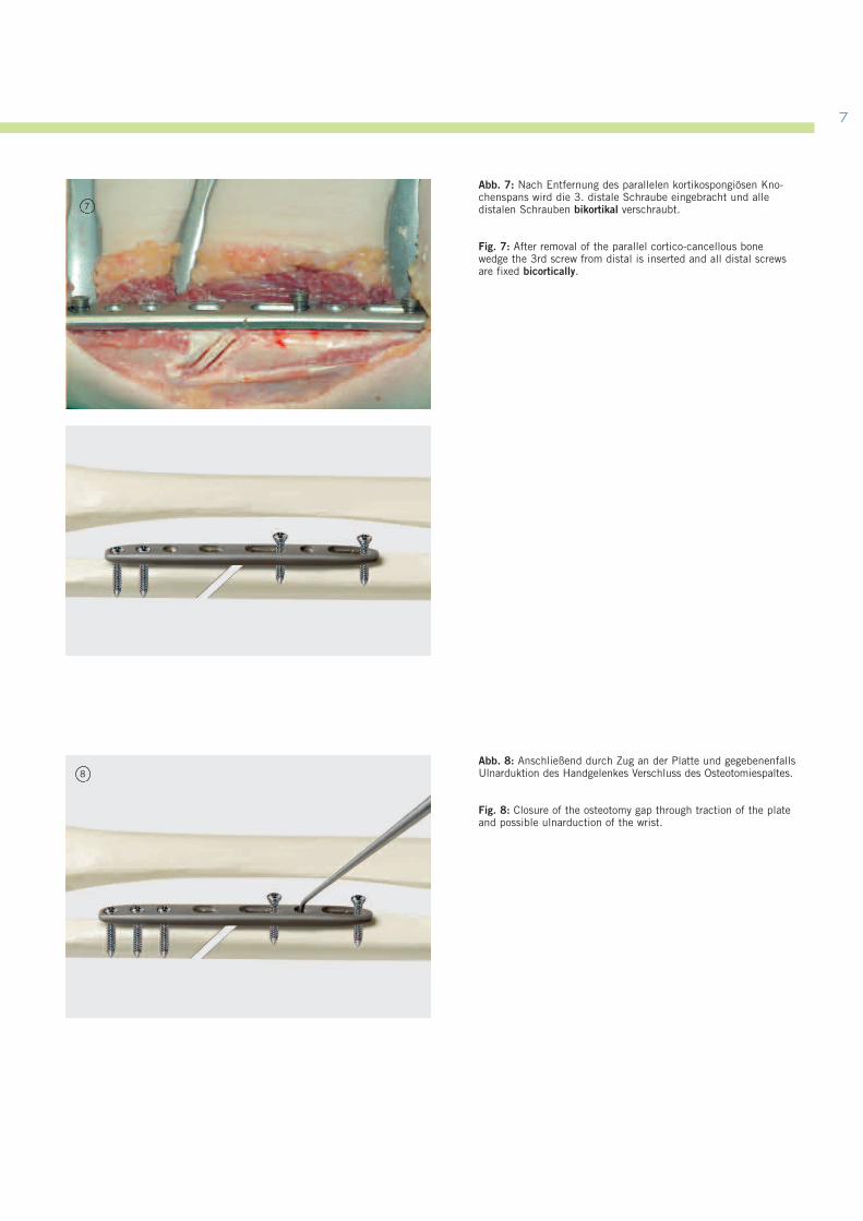
Abb. 8: Anschließend durch Zug an der Platte und gegebenenfallsUlnarduktion des Handgelenkes Verschluss des Osteotomiespaltes.
Fig. 8: Closure of the osteotomy gap through traction of the plateand possible ulnarduction of the wrist.
8
7
Abb. 7: Nach Entfernung des parallelen kortikospongiösen Kno-chenspans wird die 3. distale Schraube eingebracht und alledistalen Schrauben bikortikal verschraubt.
Fig. 7: After removal of the parallel cortico-cancellous bonewedge the 3rd screw from distal is inserted and all distal screwsare fixed bicortically.
7
Operationstechnik – UlnaverkürzungSurgical Technique – Ulna-Shortening
10
10
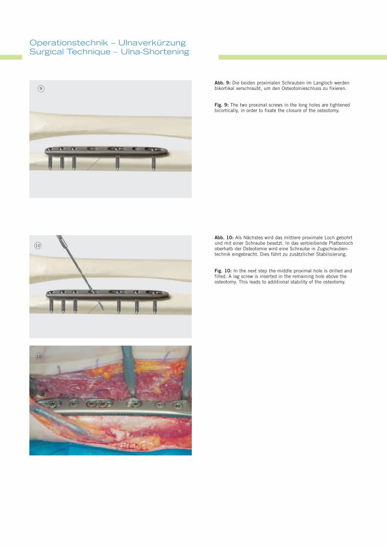
Abb. 10: Als Nächstes wird das mittlere proximale Loch gebohrtund mit einer Schraube besetzt. In das verbleibende Plattenlochoberhalb der Osteotomie wird eine Schraube in Zugschrauben-technik eingebracht. Dies führt zu zusätzlicher Stabilisierung.
Fig. 10: In the next step the middle proximal hole is drilled andfilled. A lag screw is inserted in the remaining hole above theosteotomy. This leads to additional stability of the osteotomy.
Abb. 9: Die beiden proximalen Schrauben im Langloch werdenbikortikal verschraubt, um den Osteotomieschluss zu fixieren.
Fig. 9: The two proximal screws in the long holes are tightenedbicortically, in order to fixate the closure of the osteotomy.
9
9999
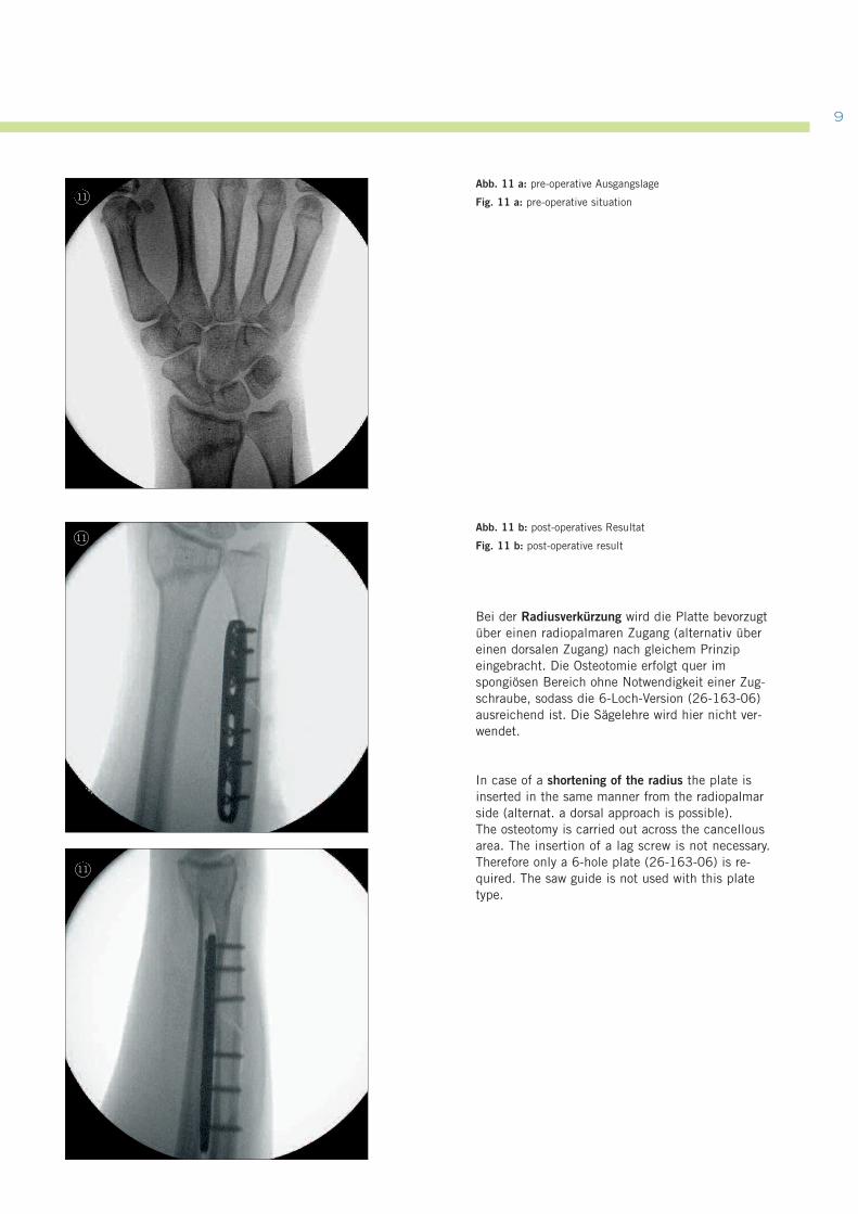
Abb. 11 a: pre-operative Ausgangslage
Fig. 11 a: pre-operative situation
Abb. 11 b: post-operatives Resultat
Fig. 11 b: post-operative result
Bei der Radiusverkürzung wird die Platte bevorzugtüber einen radiopalmaren Zugang (alternativ übereinen dorsalen Zugang) nach gleichem Prinzipeingebracht. Die Osteotomie erfolgt quer imspongiösen Bereich ohne Notwendigkeit einer Zug-schraube, sodass die 6-Loch-Version (26-163-06)ausreichend ist. Die Sägelehre wird hier nicht ver-wendet.
In case of a shortening of the radius the plate isinserted in the same manner from the radiopalmarside (alternat. a dorsal approach is possible).The osteotomy is carried out across the cancellousarea. The insertion of a lag screw is not necessary.Therefore only a 6-hole plate (26-163-06) is re-quired. The saw guide is not used with this platetype.
11
11
11
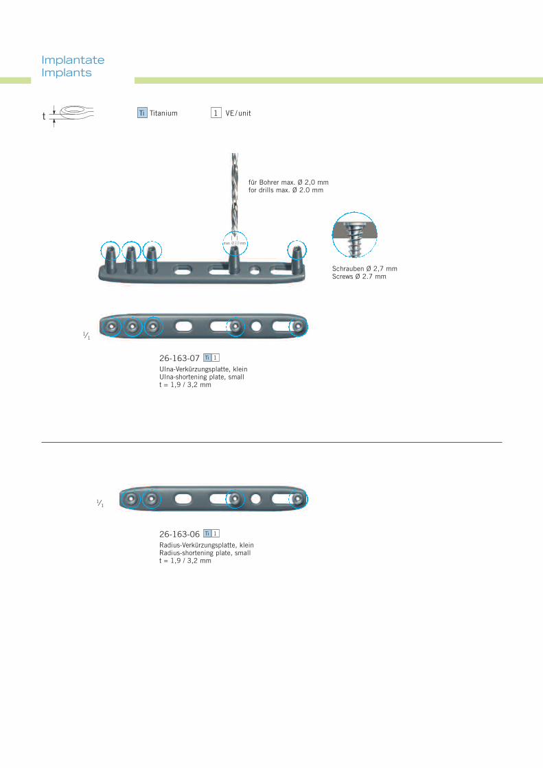
ImplantateImplants
26-163-07Ulna-Verkürzungsplatte, kleinUlna-shortening plate, smallt = 1,9 / 3,2 mm
Ti 1
26-163-06Radius-Verkürzungsplatte, kleinRadius-shortening plate, smallt = 1,9 / 3,2 mm
Ti 1
1⁄1
1⁄1
für Bohrer max. Ø 2,0 mmfor drills max. Ø 2.0 mm
Schrauben Ø 2,7 mmScrews Ø 2.7 mm
max. Ø 2,0 mm
1 VE/unitTi Titaniumt
1111
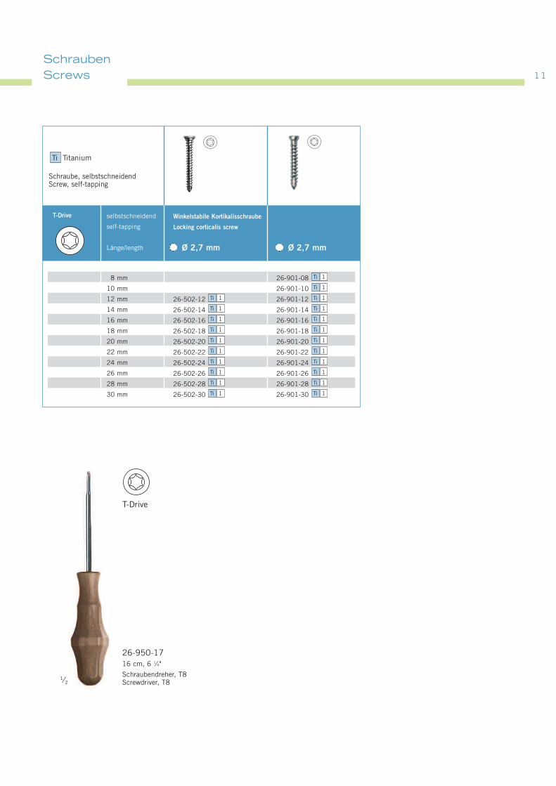
26-950-1716 cm, 6 1⁄4"
Schraubendreher, T8Screwdriver, T8
1⁄2
8 mm
10 mm
12 mm
14 mm
16 mm
18 mm
20 mm
22 mm
24 mm
26 mm
28 mm
30 mm
selbstschneidend
self-tapping
Länge/length
Winkelstabile Kortikalisschraube
Locking corticalis screw
Ø 2,7 mm Ø 2,7 mm
T-Drive
26-901-08
26-901-10
26-502-12 26-901-12
26-502-14 26-901-14
26-502-16 26-901-16
26-502-18 26-901-18
26-502-20 26-901-20
26-502-22 26-901-22
26-502-24 26-901-24
26-502-26 26-901-26
26-502-28 26-901-28
26-502-30 26-901-30 Ti 1Ti 1
Ti 1Ti 1
Ti 1Ti 1
Ti 1Ti 1
Ti 1Ti 1
Ti 1Ti 1
Ti 1Ti 1
Ti 1Ti 1
Ti 1Ti 1
Ti 1Ti 1
Ti 1
Ti 1
Schraube, selbstschneidendScrew, self-tapping
Ti Titanium
SchraubenScrews
T-Drive
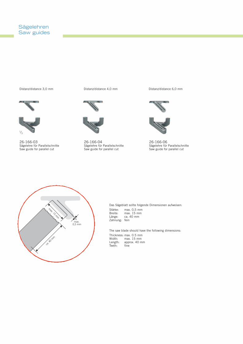
SägelehrenSaw guides
26-166-03Sägelehre für ParallelschnitteSaw guide for parallel cut
Das Sägeblatt sollte folgende Dimensionen aufweisen:
Stärke: max. 0,5 mmBreite: max. 15 mmLänge: ca. 40 mmZahnung: fein
The saw blade should have the following dimensions:
Thickness: max. 0.5 mmWidth: max. 15 mmLength: approx. 40 mmTeeth: fine
Distanz/distance 3,0 mm Distanz/distance 4,0 mm Distanz/distance 6,0 mm
1⁄2
26-166-04Sägelehre für ParallelschnitteSaw guide for parallel cut
26-166-06Sägelehre für ParallelschnitteSaw guide for parallel cut
max. 15
mm
max.0,5 mm
ca. 4
0m
m
1313
1⁄2
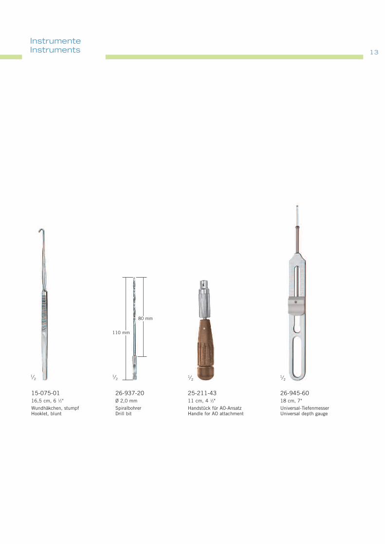
26-945-6018 cm, 7"
Universal-TiefenmesserUniversal depth gauge
25-211-4311 cm, 4 1⁄2"
Handstück für AO-AnsatzHandle for AO attachment
1⁄2
26-937-20Ø 2,0 mm
SpiralbohrerDrill bit
15-075-0116,5 cm, 6 1⁄2"
Wundhäkchen, stumpfHooklet, blunt
1⁄21⁄2
110 mm
80 mm
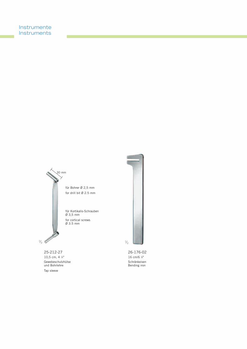
InstrumenteInstruments
InstrumenteInstruments
30 mm
1⁄2
25-212-2710,5 cm, 4 1⁄4"
Gewebeschutzhülseund Bohrlehre
Tap sleeve
für Bohrer Ø 2,5 mm
for drill bit Ø 2.5 mm
für Kortikalis-SchraubenØ 3,5 mm
for cortical screwsØ 3.5 mm
1⁄2
26-176-0216 cm/6 1⁄4"
SchränkeisenBending iron
1515
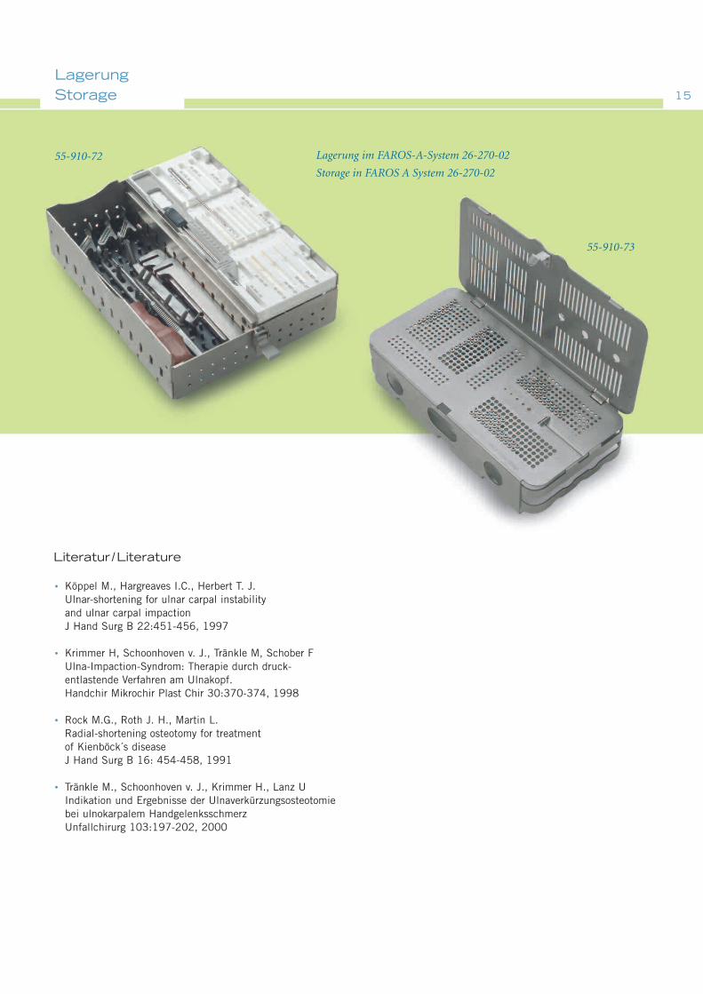
LagerungStorage
Literatur /Literature
Köppel M., Hargreaves I.C., Herbert T. J.Ulnar-shortening for ulnar carpal instabilityand ulnar carpal impactionJ Hand Surg B 22:451-456, 1997
Krimmer H, Schoonhoven v. J., Tränkle M, Schober FUlna-Impaction-Syndrom: Therapie durch druck-entlastende Verfahren am Ulnakopf.Handchir Mikrochir Plast Chir 30:370-374, 1998
Rock M.G., Roth J. H., Martin L.Radial-shortening osteotomy for treatmentof Kienböck´s diseaseJ Hand Surg B 16: 454-458, 1991
Tränkle M., Schoonhoven v. J., Krimmer H., Lanz UIndikation und Ergebnisse der Ulnaverkürzungsosteotomiebei ulnokarpalem HandgelenksschmerzUnfallchirurg 103:197-202, 2000
Lagerung im FAROS-A-System 26-270-02
Storage in FAROS A System 26-270-02
55-910-72
55-910-73
•
•
•
•

07.08 . 90-380-16-05 . Printed in Germany · Copyright by Gebrüder Martin GmbH & Co. KG · Alle Rechte vorbehalten · Technische Änderungen vorbehaltenWe reserve the right to make alterations · Cambios técnicos reservados · Sous réserve de modifications techniques · Ci riserviamo il diritto di modifiche tecniche
Gebrüder Martin GmbH & Co. KGA company of the KLS Martin GroupLudwigstaler Str. 132 · D-78532 TuttlingenPostfach 60 · D-78501 TuttlingenTel. +49 7461 706-0 · Fax +49 7461 [email protected] · www.klsmartin.com
KLS Martin Group
Karl Leibinger GmbH & Co. KG78570 MühlheimGermanyTel. +49 7463 [email protected]
KLS Martin France SARL68000 ColmarFranceTel. +33 3 89 21 [email protected]
Stuckenbrock Medizintechnik GmbH78532 TuttlingenGermanyTel. +49 7461 16 11 [email protected]
Martin Italia S.r.l.20059 Vimercate (MB)ItalyTel. +39 039 605 [email protected]
Martin Nederland/Marned B.V.1270 AG HuizenThe NetherlandsTel. +31 35 523 45 [email protected]
Gebrüder Martin GmbH & Co. KGRepresentative Office121471 MoscowRussiaTel. +7 (499) [email protected]
KLS Martin L.P.Jacksonville, Fl 32246USAOffice phone +1 904 641 [email protected]
KLS Martin GmbH + Co. KG79224 UmkirchGermanyTel. +49 7665 98 [email protected]
Nippon Martin K.K.Osaka 541-0046JapanTel. +81 6 62 28 [email protected]
Orthosurgical Implants Inc.Miami, Fl 33186USAOffice phone +1 877 969 [email protected]
Rudolf Buck GmbH78570 MühlheimGermanyTel. +49 74 63 99 [email protected]
0 2 9 7