楊素芬 特聘教授 Distinguished Prof. Su- fen Yang … · Cpk 值愈高表示製 ...
description

MANUFACTURING ENGINEERING TECHNOLOGY MECHANICAL BEHAVIOR, TESTING AND MANUFACTURING PROPERTIES OF MATERIALS
授課教師:楊宏智教授
1
【本著作除另有註明外,採取創用 CC「姓名標示-非商業性-相同方式分享」台灣 3.0版授權釋出】

2
楊宏智(台大機械系教授)
MANUFACTURING ENGINEERING
TECHNOLOGY
機械製造
CHAPTER OUTLINE1. Introduction2. Tension3. Compression4. Torsion5. Bending (Flexure)6. Hardness7. Fatigue8. Creep9. Impact10. Failure and Fracture of Materials in Manufacturing and in Service11. Residual Stresses12. Work, Heat, and Temperature
3
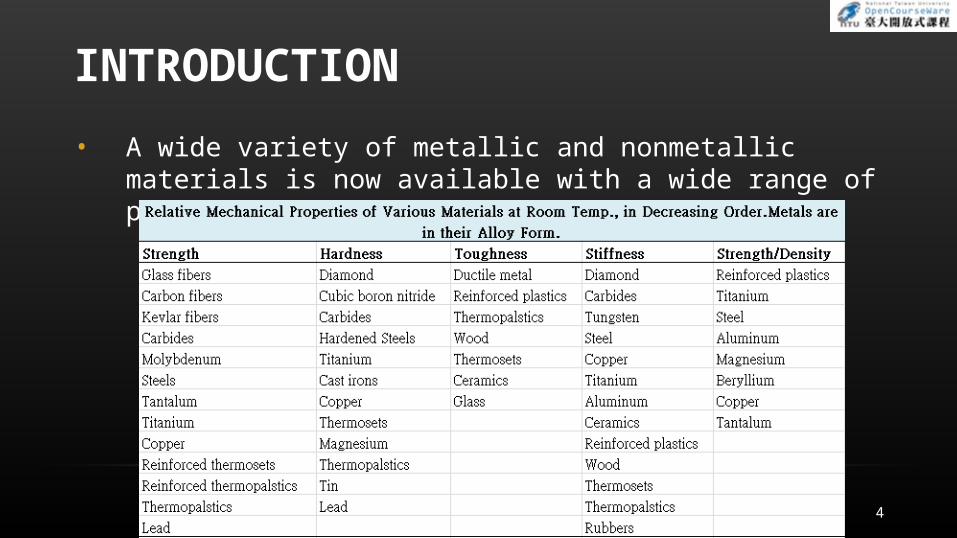
INTRODUCTION
• A wide variety of metallic and nonmetallic materials is now available with a wide range of properties
4
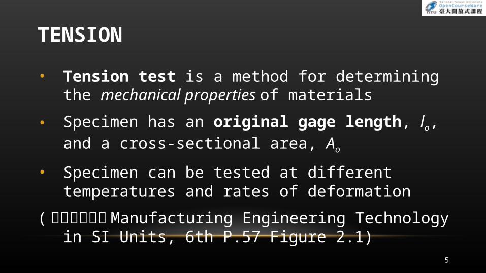
TENSION
• Tension test is a method for determining the mechanical properties of materials
• Specimen has an original gage length, lo, and a cross-sectional area, Ao
• Specimen can be tested at different temperatures and rates of deformation
(本圖表請參考Manufacturing Engineering Technology in SI Units, 6th P.57 Figure 2.1)
5
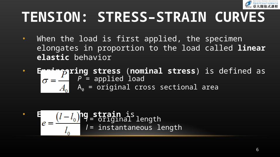
TENSION: STRESS–STRAIN CURVES• When the load is first applied, the specimen elongates in
proportion to the load called linear elastic behavior
• Engineering stress (nominal stress) is defined as
• Engineering strain is
P = applied loadA0 = original cross sectional area
l = original lengthl = instantaneous length
6
TENSION: STRESS–STRAIN CURVES
• As load increased, specimen begins nonlinear elastic deformation at a stress called the proportional limit
• Permanent (plastic) deformation occurs when the yield stress, Y, is reached
• Y is defined by drawing a line with the same slope as the linear elastic curve
• Yield stress is the stress where 0.2% offset line intersects the stress–strain curve
• Cross-sectional area decreases permanently and uniformly throughout gage length
7
TENSION: STRESS–STRAIN CURVES
• Maximum engineering stress is called the tensile strength or ultimate tensile strength (UTS)
(本圖表請參考Manufacturing Engineering Technology in SI Units, 6th P.59 Table2.2)
8
TENSION: STRESS–STRAIN CURVES
• When specimen is loaded beyond its ultimate tensile strength, it begins to neck
• Engineering stress at fracture is called breaking or fracture stress
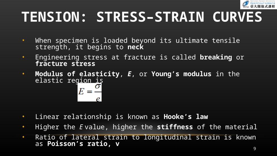
• Modulus of elasticity, E, or Young’s modulus in the elastic region is
• Linear relationship is known as Hooke’s law
• Higher the E value, higher the stiffness of the material
• Ratio of lateral strain to longitudinal strain is known as Poisson’s ratio, v
9
TENSION: DUCTILITY
• Ductility is the extent of plastic deformation that the material undergoes before fracture
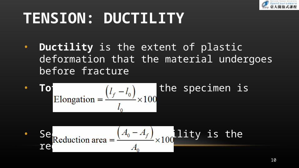
• Total elongation of the specimen is
• Second measure of ductility is the reduction of area
10
TENSION: TRUE STRESS AND TRUE STRAIN
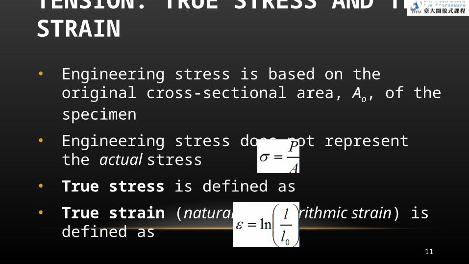
• Engineering stress is based on the original cross-sectional area, Ao, of the specimen
• Engineering stress does not represent the actual stress
• True stress is defined as
• True strain (natural or logarithmic strain) is defined as
11
TENSION: CONSTRUCTION OF STRESS–STRAIN CURVES• From load–elongation curve, divide the load by Ao and
lo
• Engineering stress–strain curve obtained
(本圖表請參考Manufacturing Engineering Technology in SI Units, 6th P.61 Figure 2.5)
12
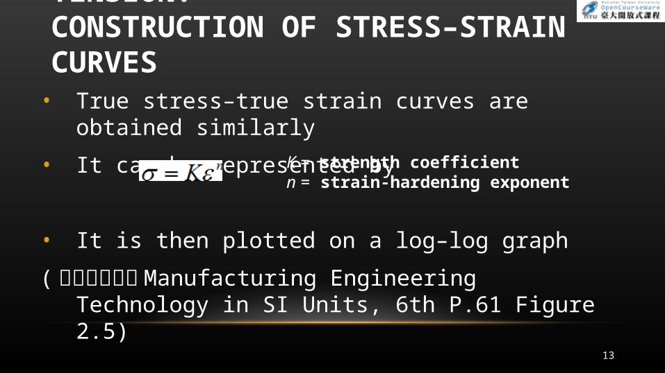
• True stress–true strain curves are obtained similarly
• It can be represented by
• It is then plotted on a log–log graph
(本圖表請參考Manufacturing Engineering Technology in SI Units, 6th P.61 Figure 2.5)
K = strength coefficientn = strain-hardening exponent
13
TENSION: CONSTRUCTION OF STRESS–STRAIN CURVES
• Area under true stress–true strain curve is called specific energy
• Area under true stress–true strain curve up to fracture is known as the toughness
14
TENSION: CONSTRUCTION OF STRESS–STRAIN CURVES
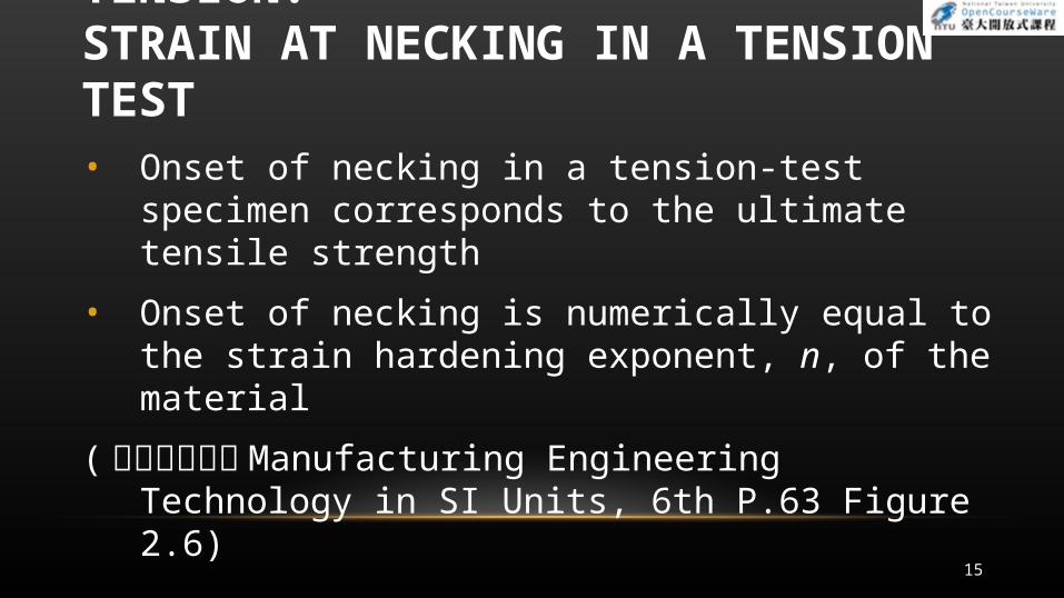
TENSION: STRAIN AT NECKING IN A TENSION TEST• Onset of necking in a tension-test specimen
corresponds to the ultimate tensile strength
• Onset of necking is numerically equal to the strain hardening exponent, n, of the material
(本圖表請參考Manufacturing Engineering Technology in SI Units, 6th P.63 Figure 2.6)
15
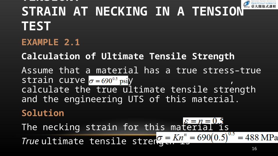
EXAMPLE 2.1
Calculation of Ultimate Tensile Strength
Assume that a material has a true stress–true strain curve given by , calculate the true ultimate tensile strength and the engineering UTS of this material.
Solution
The necking strain for this material is
True ultimate tensile strength is16
TENSION: STRAIN AT NECKING IN A TENSION TEST
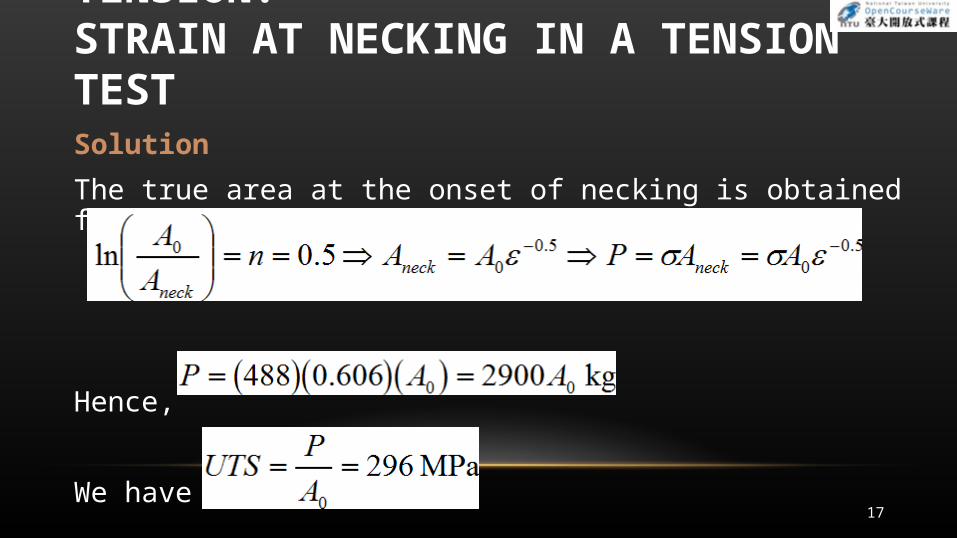
Solution
The true area at the onset of necking is obtained from
Hence,
We have17
TENSION: STRAIN AT NECKING IN A TENSION TEST
TENSION: TEMPERATURE EFFECTS
• Increasing the temperature has the following effects on stress–strain curves:
1. Ductility and toughness increase
2. Yield stress and the modulus of elasticity decrease
(本圖表請參考Manufacturing Engineering Technology in SI Units, 6th P.64 Figure 2.7)
18
HOT HARDNESS
Ability of a material to retain hardness at elevated temperatures
Typical hardness as a function of temperature for several materials
19
TENSION: RATE-OF-DEFORMATION EFFECTS
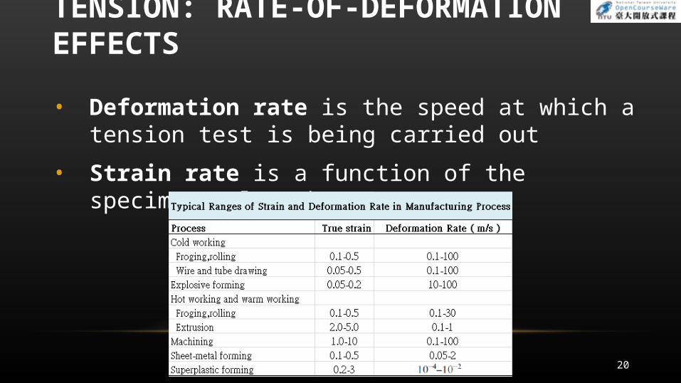
• Deformation rate is the speed at which a tension test is being carried out
• Strain rate is a function of the specimen’s length
20
TENSION: RATE-OF-DEFORMATION EFFECTS
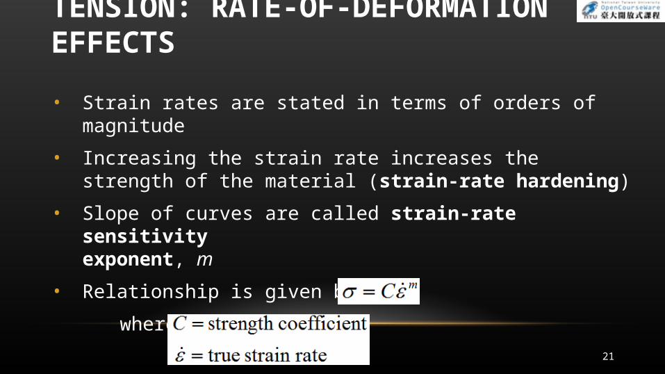
• Strain rates are stated in terms of orders of magnitude
• Increasing the strain rate increases the strength of the material (strain-rate hardening)
• Slope of curves are called strain-rate sensitivity exponent, m
• Relationship is given by
where
21
TENSION: RATE-OF-DEFORMATION EFFECTS
Superplasticity
• Superplasticity is the capability of some materials to undergo large uniform elongation prior to necking and fracture in tension
• Thus glass and thermoplastics can be formed into complex shapes
• When heated, titanium and zinc–aluminium alloys can elongate to many times their original length
22
COMPRESSION
• Compression test is where specimen is subjected to a compressive load
• Carried out by compressing a solid cylindrical specimen between two well-lubricated flat dies
• Slender specimens can buckle during this test
• Cross-sectional area of the specimen will change along its height and obtaining the stress–strain curves in compression is difficult
• When results of compression and tension tests on ductile metals are compared, true stress–true strain curves coincide
23
COMPRESSION
• Behavior is not true for brittle materials as they are stronger and more ductile in compression than in tension
• When a metal is subjected to tension into the plastic range, the yield stress in compression is lower than that in tension
• Phenomenon known as Bauschinger effect
24
COMPRESSION
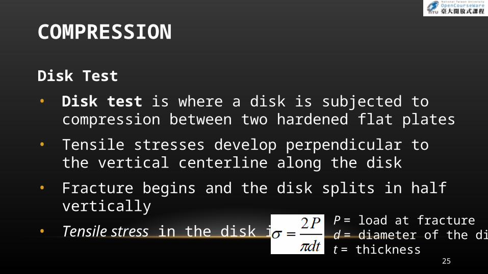
Disk Test
• Disk test is where a disk is subjected to compression between two hardened flat plates
• Tensile stresses develop perpendicular to the vertical centerline along the disk
• Fracture begins and the disk splits in half vertically
• Tensile stress in the disk is P = load at fractured = diameter of the diskt = thickness
25
TORSION
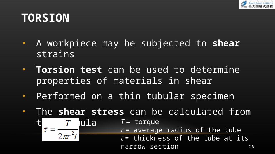
• A workpiece may be subjected to shear strains
• Torsion test can be used to determine properties of materials in shear
• Performed on a thin tubular specimen
• The shear stress can be calculated from the formula
T = torquer = average radius of the tubet = thickness of the tube at its narrow section
26
TORSION
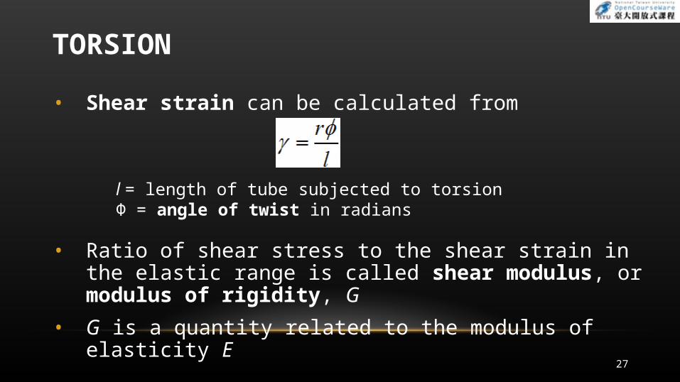
• Shear strain can be calculated from
• Ratio of shear stress to the shear strain in the elastic range is called shear modulus, or modulus of rigidity, G
• G is a quantity related to the modulus of elasticity E
l = length of tube subjected to torsion Φ = angle of twist in radians
27
BENDING (FLEXURE)
• Test method for brittle materials is the bend or flexure test
• Involves a specimen that has a rectangular cross section and is supported
• The longitudinal stresses are tensile at their lower surfaces and compressive at their upper surfaces
• The stress at fracture in bending is known as the modulus of rupture, or transverse rupture strength
28
HARDNESS
• Hardness is a indication of the strength of the material and of its resistance to scratching and to wear
• Defined as resistance to permanent indentation
• Resistance to indentation depends on the shape of the indenter and on the load applied
29

HARDNESS: HARDNESS TESTS
• Several test methods use different indenter materials and shapes
30
HARDNESS: HARDNESS TESTS
Brinell Test
• Brinell hardness number (HB) is the ratio P to the curved surface area of the indentation
• Harder the material to be tested, the smaller the impression
(本圖表請參考Manufacturing Engineering Technology in SI Units, 6th P.70 Figure 2.13, 2.14)
31

HARDNESS: HARDNESS TESTS
Rockwell Test
• Measures the depth of penetration
• Indenter is pressed onto the surface
• Difference in the depths of penetration is a measure of the hardness of the material
Vickers Test
• Uses a pyramid-shaped diamond indenter
• Vickers hardness number is indicated by HV32
HARDNESS: HARDNESS TESTS
Knoop Test
• Uses a diamond indenter in the shape of an elongated pyramid
• Hardness number is indicated by HK
• It is a microhardness test, suitable for very thin specimens and brittle materials
Scleroscope and Leeb Test
• Uses a diamond-tipped indenter dropping onto the specimen from a certain height
• Hardness is related to the rebound of the indenter33
HARDNESS: HARDNESS TESTS
Mohs Hardness
• Based on the capability of one material to scratch another
• Material with a higher Mohs hardness number scratches one with a lower number
Shore Test and Durometer
• Depth of penetration is measured after 1 second
• The hardness is inversely related to the penetration34
HARDNESS: HARDNESS AND STRENGTH
• Hardness is the resistance to permanent indentation
• Hardness of a coldworked metal is about 3 times its yield stress Y
• For annealed metals, the hardness is about 5 times Y
• For the ultimate tensile strength (UTS) and the Brinell hardness (HB) of steel,
UTS = 3.5(HB) where UTS in MPa
UTS = 500(HB) where UTS in psi35
HARDNESS: HARDNESS-TESTING PROCEDURES
• Zone of deformation under the indenter must be allowed to develop freely
• Location of the indenter and thickness of the specimen are important considerations
• Thickness of the specimen should be at least 10 times the depth of penetration of the indenter
• The values obtained from different hardness tests, on different scales can be interrelated
36
37
HARDNESS: HARDNESS-TESTING PROCEDURES
• 本圖表請參考Manufacturing Engineering Technology in SI Units, 6th P.73 Figure 2.15
EXAMPLE 2.2
Calculation of Modulus of Resilience from Hardness
A piece of steel is highly deformed at room temperature. Its hardness is found to be 300 HB. Estimate the area under the stress–strain curve up to the yield point (that is, the resilience) for this material if the yield strength is one-third the Brinell hardness.
38
HARDNESS: HARDNESS-TESTING PROCEDURES
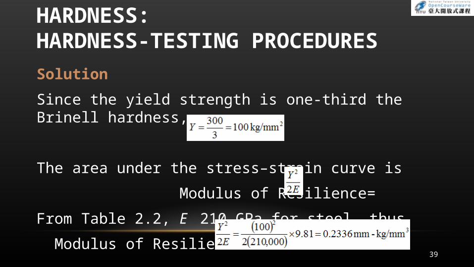
Solution
Since the yield strength is one-third the Brinell hardness,
The area under the stress–strain curve is
Modulus of Resilience=
From Table 2.2, E 210 GPa for steel, thus
Modulus of Resilience=39
HARDNESS: HARDNESS-TESTING PROCEDURES
FATIGUE
• Cyclic stresses may be caused by fluctuating mechanical loads, e.g. gear and rotating machine elements
• Failure is due to cracks that grow with every stress cycle and propagate until a critical crack length is reached
• Known as fatigue failure
• Fatigue test methods involve testing specimens under a combination of tension and bending
40
FATIGUE
• Stress amplitude is defined as the maximum stress
• Typical plots are called S–N curves
• Maximum stress without fatigue failure, regardless of the number of cycles, is known as the endurance limit or fatigue limit
• Endurance limit for metals can be related to their ultimate tensile strength
41
CREEP
• Creep is the permanent elongation of a component under a static load maintained for a period of time
• Occurs in metals and certain nonmetallic materials (thermoplastics and rubber)
• Mechanism of creep at elevated temperature in metals is due to grain-boundary sliding
• Creep test consists of subjecting a specimen to a constant tensile load at elevated temperature
• Measure the changes in length at various time increments42
CREEP
• Creep curve consists of primary, secondary, and tertiary stages
• Specimen eventually fails by necking and fracture, called rupture or creep rupture
(本圖表請參考Manufacturing Engineering Technology in SI Units, 6th P.75 Figure 2.18)
43
CREEP
Stress Relaxation
• Stresses resulting from loading of a structural component decrease in magnitude over a period of time
• The dimensions of the component remain constant
• Stress relaxation is common and important in thermoplastics
44
IMPACT
• Materials are subjected to impact, or dynamic loading during manufacturing
• Impact test consists of placing a notched specimen in an impact tester and breaking the specimen with a swinging pendulum
• Specimen is supported at both ends for Charpy test
• Specimen is supported at one end like a cantilever beam in Izod test
45
FAILURE AND FRACTURE OF MATERIALS INMANUFACTURING AND IN SERVICE
• Failure influences the selection of a material for a application, the methods of manufacturing, and the service life of the component
• 2 types of failure:
1. Fracture
2. Buckling
46
FAILURE AND FRACTURE OF MATERIALS IN MANUFACTURING AND IN SERVICE : DUCTILE FRACTURE
• Ductile fracture is plastic deformation which precedes failure
• Metals and alloys neck down to a finite area and then fail
• Ductile fracture takes place along planes on which the shear stress is a maximum
• Surface of ductile fracture shows a fibrous pattern with dimples
47
FAILURE AND FRACTURE OF MATERIALS IN MANUFACTURING AND IN SERVICE : DUCTILE FRACTURE
Effects of Inclusions
• Inclusions have an influence on ductile fracture and the workability of materials
• Consist of impurities of various kinds and of second-phase particles
• Voids and porosity can develop during processing of metals
• 2 factors affect void formation:
1. Bond between an inclusion and the matrix
2. Hardness of the inclusion
48
FAILURE AND FRACTURE OF MATERIALS IN MANUFACTURING AND IN SERVICE : DUCTILE FRACTURE
Transition Temperature
• Metals undergo a sharp change in ductility and toughness across transition temperature
• Phenomenon occurs in bcc and in some hcp metals
• Rarely exhibited by face-centered cubic metals
49
FAILURE AND FRACTURE OF MATERIALS IN MANUFACTURING AND IN SERVICE : DUCTILE FRACTURE
Strain Aging
• Strain aging is where carbon atoms in steels segregate to dislocations and pinning the dislocations
• This increases the resistance to their movement
• Thus increased strength and reduced ductility
• When occurs in just a few hours at a higher temperature; it is called accelerated strain aging
50
FAILURE AND FRACTURE OF MATERIALS IN MANUFACTURING AND IN SERVICE : BRITTLE FRACTURE
• Brittle fracture occurs with little plastic deformation
• In tension, fracture takes place along the cleavage plane where normal tensile stress is a maximum
• Low temperature and a high rate of deformation promote brittle fracture
• It has bright granular appearance due to changes in the direction of the cleavage planes as the crack propagates
51
FAILURE AND FRACTURE OF MATERIALS IN MANUFACTURING AND IN SERVICE : BRITTLE FRACTURE
Defects
• Under tension, the sharp tip of the crack is subjected to high tensile stresses, which propagate the crack rapidly
• Presence of defects cause brittle materials to be weak in tension
• Fracture paths in polycrystalline metals are transgranular where crack propagates through the grain
52
FAILURE AND FRACTURE OF MATERIALS IN MANUFACTURING AND IN SERVICE : BRITTLE FRACTURE
Fatigue Fracture
• Fatigue fracture occurs in a brittle manner
• Cracks can propagate over time and lead to total and sudden failure of the part
• Fracture surface in fatigue is characterized by beach marks
53
FAILURE AND FRACTURE OF MATERIALS IN MANUFACTURING AND IN SERVICE : BRITTLE FRACTURE
Improving Fatigue Strength
• Fatigue life is influenced by the method of preparation of the surfaces of the part or specimen
• Fatigue strength improved by
1. Inducing compressive residual stresses on surfaces
2. Case hardening
3. Providing a fine surface finish
4. Selecting appropriate materials54
FAILURE AND FRACTURE OF MATERIALS IN MANUFACTURING AND IN SERVICE : BRITTLE FRACTURE
Hydrogen Embrittlement
• Presence of hydrogen can reduce ductility and cause embrittlement and premature failure in many metals, alloys, and nonmetallic materials
• Known as hydrogen embrittlement
• Severe in high strength steels
55
RESIDUAL STRESSES
• When workpieces are subjected to plastic deformation, they develop residual stresses
• Stresses that remain within a part after it has been formed and all the external forces are removed
56
RESIDUAL STRESSES
• Equilibrium of residual stresses is disturbed by the removal of a layer of material from the part
• Disturbances of residual stresses lead to warping of parts
• Equilibrium of residual stresses can be disturbed by relaxation of these stresses over a period of time
• Also be disturbed by relaxation of stresses over a period of time
57
RESIDUAL STRESSES
• Tensile residual stresses on the surface of a part are undesirable
• They lower the fatigue life and fracture strength of the part
• Tensile residual stresses can lead to stress cracking or to stress–corrosion cracking of manufactured products
Reduction and Elimination of Residual Stresses
• Residual stresses reduced by stress-relief annealing or further deformation of the part
58
WORK, HEAT, AND TEMPERATURE
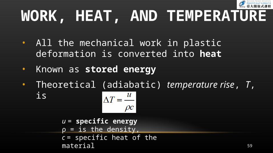
• All the mechanical work in plastic deformation is converted into heat
• Known as stored energy
• Theoretical (adiabatic) temperature rise, T, is
u = specific energy ρ = is the density,c = specific heat of the material
59
FLUID PROPERTIES AND MANUFACTURING
Fluid flow – they take the shape of the container that holds them
Many manufacturing processes are accomplished on materials converted from solid to liquid by heating
• Called solidification processes Examples:
• Metals are cast in molten state
• Glass is formed in a heated and fluid state
• Polymers are almost always shaped as fluids
60