
Woma Tilbehørskatalog Ultrahøytrykk Tankrengjøring
50
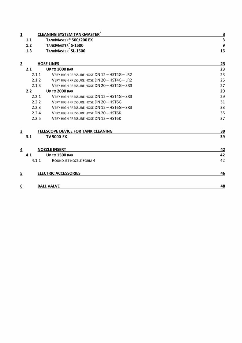
WOMA Accessories Tank Cleaning 2015
description
Â
Transcript of Woma Tilbehørskatalog Ultrahøytrykk Tankrengjøring
WOMA Accessories Tank Cleaning
2015
1 CLEANING SYSTEM TANKMASTER® 3 1.1 TANKMASTER® 500/200 EX 3 1.2 TANKMASTER
® S-1500 9
1.3 TANKMASTER® SL-1500 16
2 HOSE LINES 23 2.1 UP TO 1000 BAR 23
2.1.1 VERY HIGH PRESSURE HOSE DN 12 – HST4G – LR2 23 2.1.2 VERY HIGH PRESSURE HOSE DN 20 – HST4G – LR2 25 2.1.3 VERY HIGH PRESSURE HOSE DN 20 – HST4G – SR3 27
2.2 UP TO 2000 BAR 29 2.2.1 VERY HIGH PRESSURE HOSE DN 12 – HST4G – SR3 29 2.2.2 VERY HIGH PRESSURE HOSE DN 20 – HST6G 31 2.2.3 VERY HIGH PRESSURE HOSE DN 12 – HST6G – SR3 33 2.2.4 VERY HIGH PRESSURE HOSE DN 20 – HST6K 35 2.2.5 VERY HIGH PRESSURE HOSE DN 12 – HST6K 37
3 TELESCOPE DEVICE FOR TANK CLEANING 39 3.1 TV 5000-EX 39
4 NOZZLE INSERT 42 4.1 UP TO 1500 BAR 42
4.1.1 ROUND JET NOZZLE FORM 4 42
5 ELECTRIC ACCESSORIES 46
6 BALL VALVE 48
Copyright © 2015 WOMA GmbH | Subject to change | Status: April 2015 3
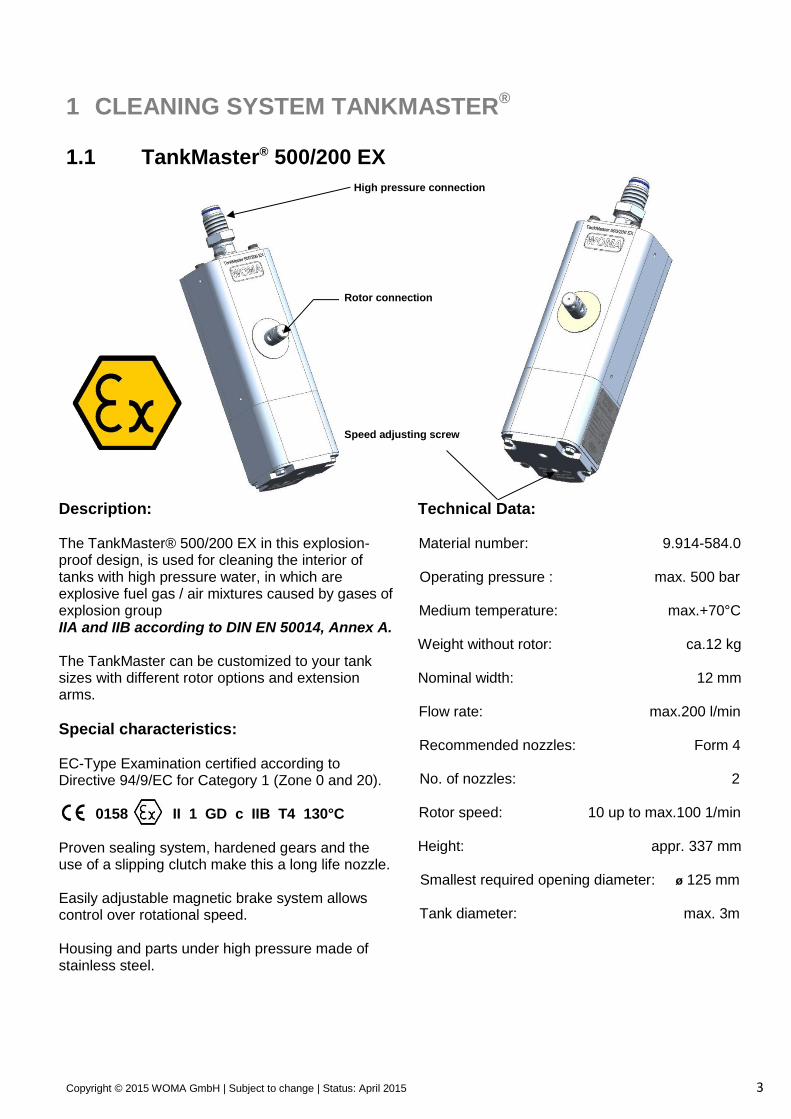
1 CLEANING SYSTEM TANKMASTER®
1.1 TankMaster® 500/200 EX
Description: The TankMaster® 500/200 EX in this explosion-proof design, is used for cleaning the interior of tanks with high pressure water, in which are explosive fuel gas / air mixtures caused by gases of explosion group IIA and IIB according to DIN EN 50014, Annex A. The TankMaster can be customized to your tank sizes with different rotor options and extension arms.
Special characteristics: EC-Type Examination certified according to Directive 94/9/EC for Category 1 (Zone 0 and 20). 0158 II 1 GD c IIB T4 130°C Proven sealing system, hardened gears and the use of a slipping clutch make this a long life nozzle. Easily adjustable magnetic brake system allows control over rotational speed. Housing and parts under high pressure made of stainless steel.
Technical Data:
Material number: 9.914-584.0
Operating pressure : max. 500 bar
Medium temperature: max.+70°C
Weight without rotor: ca.12 kg
Nominal width: 12 mm
Flow rate: max.200 l/min
Recommended nozzles: Form 4
No. of nozzles: 2
Rotor speed: 10 up to max.100 1/min
Height: appr. 337 mm
Smallest required opening diameter: ø 125 mm
Tank diameter: max. 3m
Speed adjusting screw
Rotor connection
High pressure connection
Copyright © 2015 WOMA GmbH | Subject to change | Status: April 2015 4
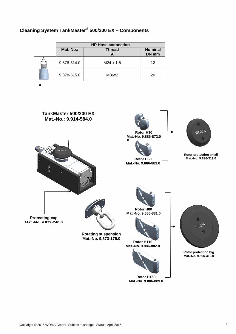
Cleaning System TankMaster® 500/200 EX – Components
HP Hose connection
Mat.-No.: Thread A
Nominal DN mm
9.878-514.0 M24 x 1,5 12
9.878-515.0 M36x2 20
TankMaster 500/200 EX Mat.-No.: 9.914-584.0
Rotating suspension Mat.-No. 9.873-175.0
Protecting cap Mat.-No. 9.873-240.0
Rotor H30 Mat.-No. 9.886-872.0
Rotor H50 Mat.-No. 9.886-883.0
Rotor H80 Mat.-No. 9.886-881.0
Rotor H110 Mat.-No. 9.886-882.0
Rotor protection big
Mat.-No. 9.896-312.0
Rotor protection small Mat.-No. 9.896-311.0
A
Rotor H150 Mat.-No. 9.886-889.0
Copyright © 2015 WOMA GmbH | Subject to change | Status: April 2015 5
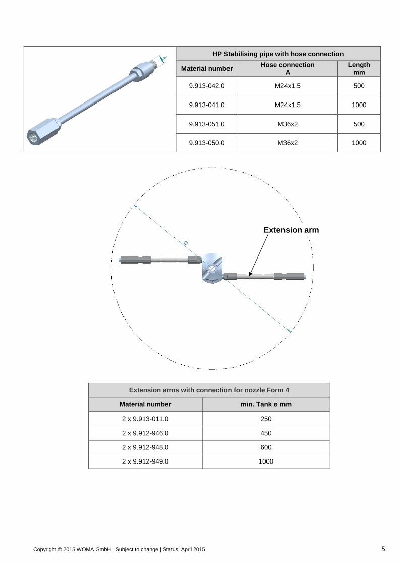
HP Stabilising pipe with hose connection
Material number Hose connection
A Length
mm
9.913-042.0 M24x1,5 500
9.913-041.0 M24x1,5 1000
9.913-051.0 M36x2 500
9.913-050.0 M36x2 1000
Extension arms with connection for nozzle Form 4
Material number min. Tank ø mm
2 x 9.913-011.0 250
2 x 9.912-946.0 450
2 x 9.912-948.0 600
2 x 9.912-949.0 1000
Extension arm
Copyright © 2015 WOMA GmbH | Subject to change | Status: April 2015 6
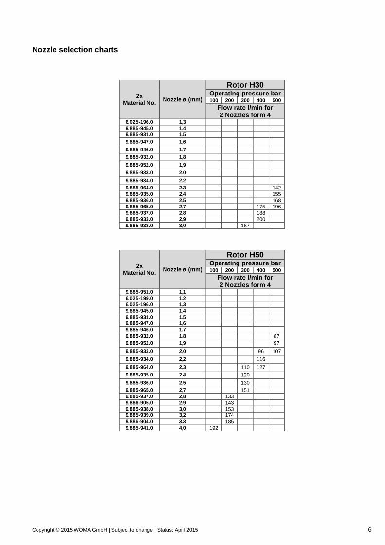
Nozzle selection charts
2x Material No.
Nozzle ø (mm)
Rotor H50 Operating pressure bar 100 200 300 400 500
Flow rate l/min for 2 Nozzles form 4
9.885-951.0 1,1
6.025-199.0 1,2
6.025-196.0 1,3
9.885-945.0 1,4
9.885-931.0 1,5
9.885-947.0 1,6
9.885-946.0 1,7
9.885-932.0 1,8 87
9.885-952.0 1,9 97
9.885-933.0 2,0 96 107
9.885-934.0 2,2 116
9.885-964.0 2,3 110 127
9.885-935.0 2,4 120
9.885-936.0 2,5 130
9.885-965.0 2,7 151
9.885-937.0 2,8 133
9.886-905.0 2,9 143
9.885-938.0 3,0 153
9.885-939.0 3,2 174
9.886-904.0 3,3 185
9.885-941.0 4,0 192
2x Material No.
Nozzle ø (mm)
Rotor H30 Operating pressure bar 100 200 300 400 500
Flow rate l/min for 2 Nozzles form 4
6.025-196.0 1,3
9.885-945.0 1,4
9.885-931.0 1,5
9.885-947.0 1,6
9.885-946.0 1,7
9.885-932.0 1,8
9.885-952.0 1,9
9.885-933.0 2,0
9.885-934.0 2,2
9.885-964.0 2,3 142
9.885-935.0 2,4 155
9.885-936.0 2,5 168
9.885-965.0 2,7 175 196
9.885-937.0 2,8 188
9.885-933.0 2,9 200
9.885-938.0 3,0 187
Copyright © 2015 WOMA GmbH | Subject to change | Status: April 2015 7
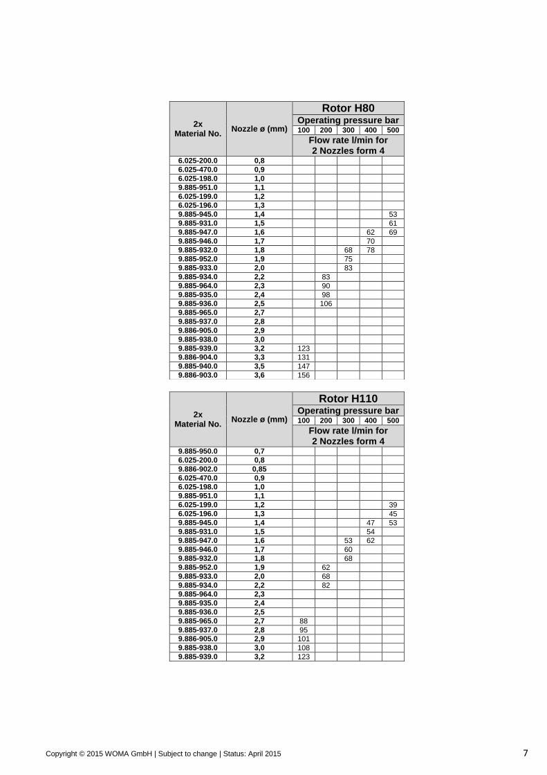
2x Material No.
Nozzle ø (mm)
Rotor H80 Operating pressure bar 100 200 300 400 500
Flow rate l/min for 2 Nozzles form 4
6.025-200.0 0,8
6.025-470.0 0,9
6.025-198.0 1,0
9.885-951.0 1,1
6.025-199.0 1,2
6.025-196.0 1,3
9.885-945.0 1,4 53
9.885-931.0 1,5 61
9.885-947.0 1,6 62 69
9.885-946.0 1,7 70
9.885-932.0 1,8 68 78
9.885-952.0 1,9 75
9.885-933.0 2,0 83
9.885-934.0 2,2 83
9.885-964.0 2,3 90
9.885-935.0 2,4 98
9.885-936.0 2,5 106
9.885-965.0 2,7
9.885-937.0 2,8
9.886-905.0 2,9
9.885-938.0 3,0
9.885-939.0 3,2 123
9.886-904.0 3,3 131
9.885-940.0 3,5 147
9.886-903.0 3,6 156
2x Material No.
Nozzle ø (mm)
Rotor H110 Operating pressure bar 100 200 300 400 500
Flow rate l/min for 2 Nozzles form 4
9.885-950.0 0,7
6.025-200.0 0,8
9.886-902.0 0,85
6.025-470.0 0,9
6.025-198.0 1,0
9.885-951.0 1,1
6.025-199.0 1,2 39
6.025-196.0 1,3 45
9.885-945.0 1,4 47 53
9.885-931.0 1,5 54
9.885-947.0 1,6 53 62
9.885-946.0 1,7 60
9.885-932.0 1,8 68
9.885-952.0 1,9 62
9.885-933.0 2,0 68
9.885-934.0 2,2 82
9.885-964.0 2,3
9.885-935.0 2,4
9.885-936.0 2,5
9.885-965.0 2,7 88
9.885-937.0 2,8 95
9.886-905.0 2,9 101
9.885-938.0 3,0 108
9.885-939.0 3,2 123
Copyright © 2015 WOMA GmbH | Subject to change | Status: April 2015 8
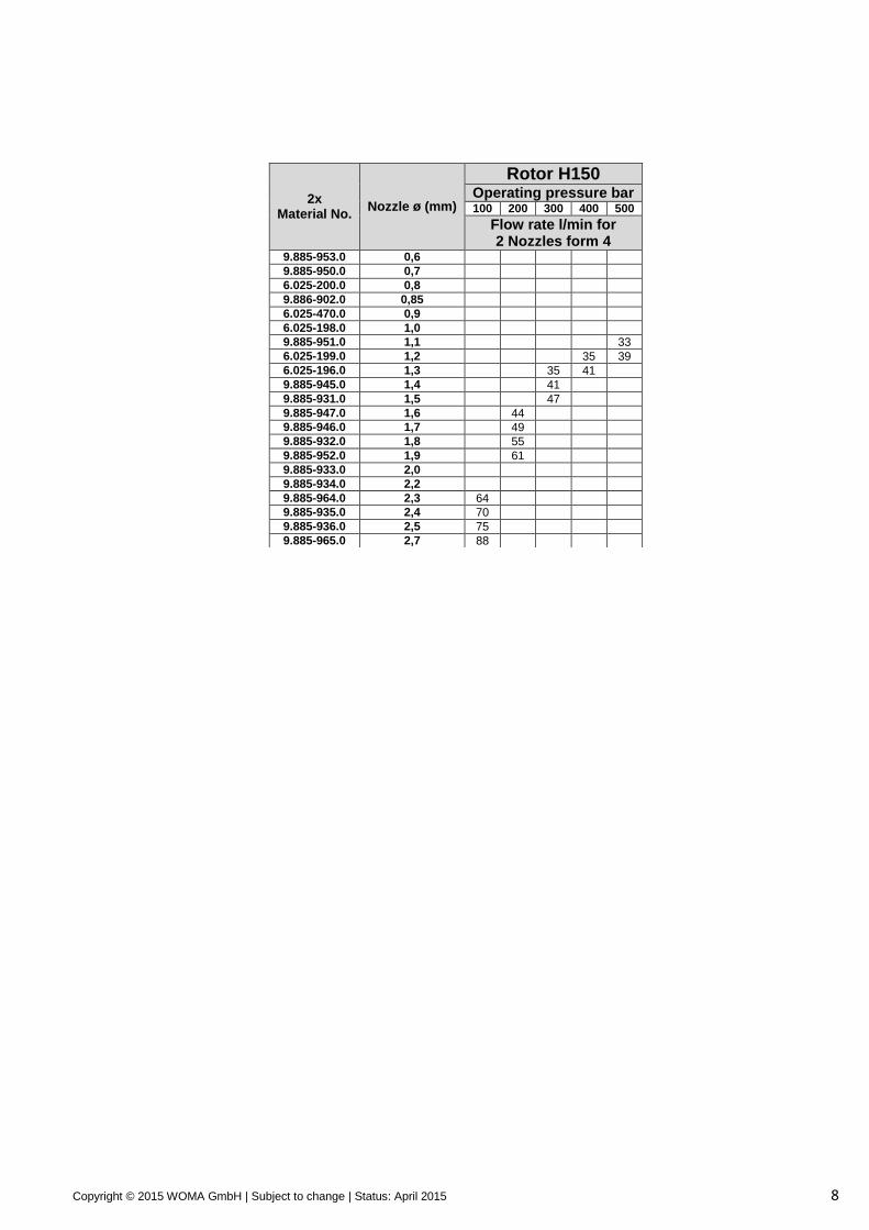
2x Material No.
Nozzle ø (mm)
Rotor H150 Operating pressure bar 100 200 300 400 500
Flow rate l/min for 2 Nozzles form 4
9.885-953.0 0,6
9.885-950.0 0,7
6.025-200.0 0,8
9.886-902.0 0,85
6.025-470.0 0,9
6.025-198.0 1,0
9.885-951.0 1,1 33
6.025-199.0 1,2 35 39
6.025-196.0 1,3 35 41
9.885-945.0 1,4 41
9.885-931.0 1,5 47
9.885-947.0 1,6 44
9.885-946.0 1,7 49
9.885-932.0 1,8 55
9.885-952.0 1,9 61
9.885-933.0 2,0
9.885-934.0 2,2
9.885-964.0 2,3 64
9.885-935.0 2,4 70
9.885-936.0 2,5 75
9.885-965.0 2,7 88
Copyright © 2015 WOMA GmbH | Subject to change | Status: April 2015 9
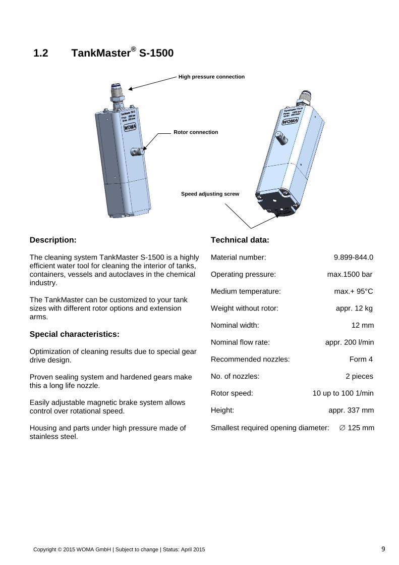
1.2 TankMaster® S-1500
Description: The cleaning system TankMaster S-1500 is a highly efficient water tool for cleaning the interior of tanks, containers, vessels and autoclaves in the chemical industry. The TankMaster can be customized to your tank sizes with different rotor options and extension arms.
Special characteristics: Optimization of cleaning results due to special gear drive design. Proven sealing system and hardened gears make this a long life nozzle. Easily adjustable magnetic brake system allows control over rotational speed. Housing and parts under high pressure made of stainless steel.
Technical data: Material number: 9.899-844.0 Operating pressure: max.1500 bar Medium temperature: max.+ 95°C Weight without rotor: appr. 12 kg Nominal width: 12 mm Nominal flow rate: appr. 200 l/min Recommended nozzles: Form 4 No. of nozzles: 2 pieces Rotor speed: 10 up to 100 1/min Height: appr. 337 mm
Smallest required opening diameter: 125 mm
Speed adjusting screw
Rotor connection
High pressure connection
Copyright © 2015 WOMA GmbH | Subject to change | Status: April 2015 10
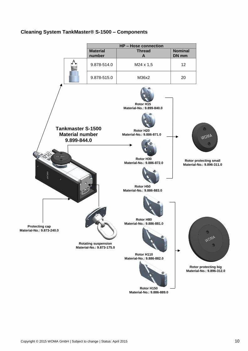
Cleaning System TankMaster® S-1500 – Components
HP – Hose connection
Material number
Thread A
Nominal DN mm
9.878-514.0 M24 x 1,5 12
9.878-515.0 M36x2 20
Tankmaster S-1500 Material number
9.899-844.0
Rotating suspension
Material-No.: 9.873-175.0
Protecting cap
Material-No.: 9.873-240.0
Rotor H20
Material-No.: 9.886-871.0
Rotor H30
Material-No.: 9.886-872.0
Rotor H50
Material-No.: 9.886-883.0
Rotor H80
Material-No.: 9.886-881.0
Rotor H110
Material-No.: 9.886-882.0
Rotor protecting big
Material-No.: 9.896-312.0
Rotor protecting small
Material-No.: 9.896-311.0
A
Rotor H150
Material-No.: 9.886-889.0
Rotor H15
Material-No.: 9.899-840.0
Copyright © 2015 WOMA GmbH | Subject to change | Status: April 2015 11
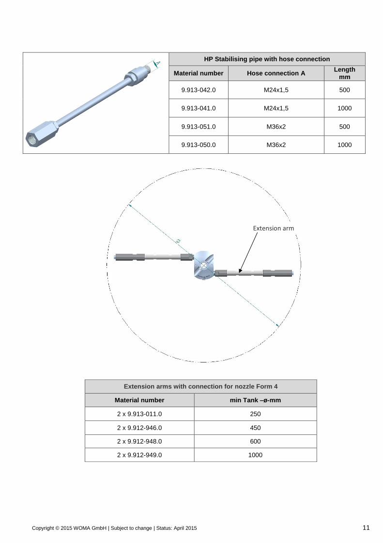
HP Stabilising pipe with hose connection
Material number Hose connection A Length
mm
9.913-042.0 M24x1,5 500
9.913-041.0 M24x1,5 1000
9.913-051.0 M36x2 500
9.913-050.0 M36x2 1000
Extension arms with connection for nozzle Form 4
Material number min Tank –ø-mm
2 x 9.913-011.0 250
2 x 9.912-946.0 450
2 x 9.912-948.0 600
2 x 9.912-949.0 1000
Extension arm
Copyright © 2015 WOMA GmbH | Subject to change | Status: April 2015 12
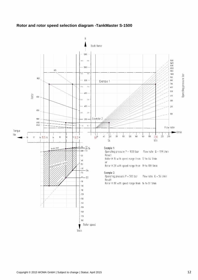
Rotor and rotor speed selection diagram -TankMaster S-1500
Copyright © 2015 WOMA GmbH | Subject to change | Status: April 2015 13
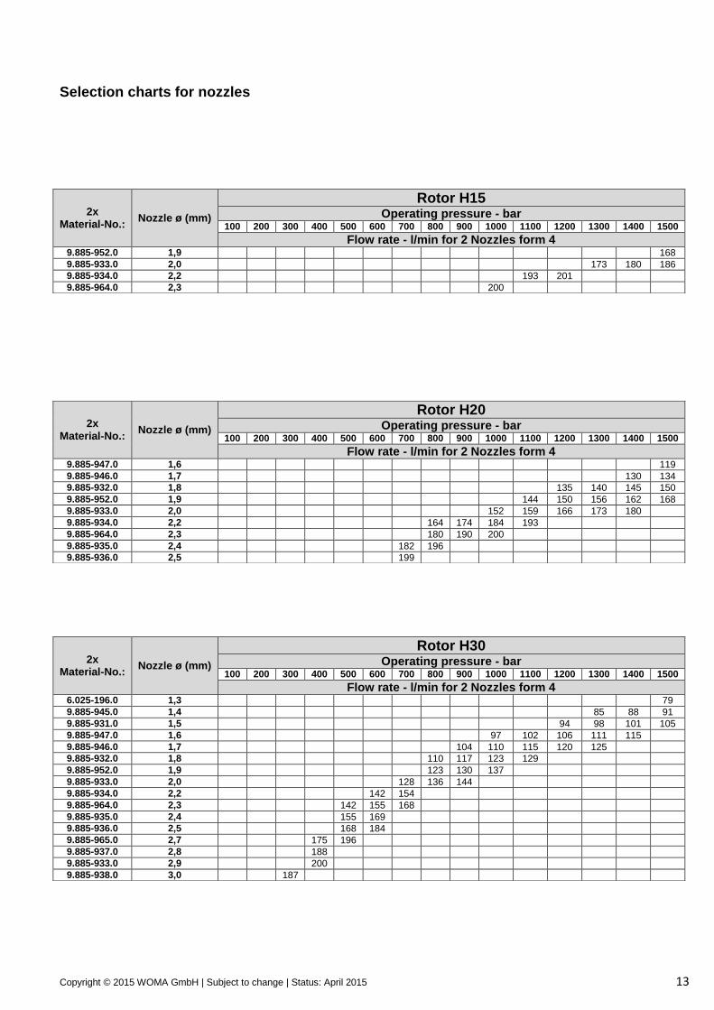
Selection charts for nozzles
2x Material-No.:
Nozzle ø (mm)
Rotor H15 Operating pressure - bar
100 200 300 400 500 600 700 800 900 1000 1100 1200 1300 1400 1500
Flow rate - l/min for 2 Nozzles form 4 9.885-952.0 1,9 168
9.885-933.0 2,0 173 180 186
9.885-934.0 2,2 193 201
9.885-964.0 2,3 200
2x Material-No.:
Nozzle ø (mm)
Rotor H20 Operating pressure - bar
100 200 300 400 500 600 700 800 900 1000 1100 1200 1300 1400 1500
Flow rate - l/min for 2 Nozzles form 4 9.885-947.0 1,6 119
9.885-946.0 1,7 130 134
9.885-932.0 1,8 135 140 145 150
9.885-952.0 1,9 144 150 156 162 168
9.885-933.0 2,0 152 159 166 173 180
9.885-934.0 2,2 164 174 184 193
9.885-964.0 2,3 180 190 200
9.885-935.0 2,4 182 196
9.885-936.0 2,5 199
2x Material-No.:
Nozzle ø (mm)
Rotor H30 Operating pressure - bar
100 200 300 400 500 600 700 800 900 1000 1100 1200 1300 1400 1500
Flow rate - l/min for 2 Nozzles form 4
6.025-196.0 1,3 79
9.885-945.0 1,4 85 88 91
9.885-931.0 1,5 94 98 101 105
9.885-947.0 1,6 97 102 106 111 115
9.885-946.0 1,7 104 110 115 120 125
9.885-932.0 1,8 110 117 123 129
9.885-952.0 1,9 123 130 137
9.885-933.0 2,0 128 136 144
9.885-934.0 2,2 142 154
9.885-964.0 2,3 142 155 168
9.885-935.0 2,4 155 169
9.885-936.0 2,5 168 184
9.885-965.0 2,7 175 196
9.885-937.0 2,8 188
9.885-933.0 2,9 200
9.885-938.0 3,0 187
Copyright © 2015 WOMA GmbH | Subject to change | Status: April 2015 14
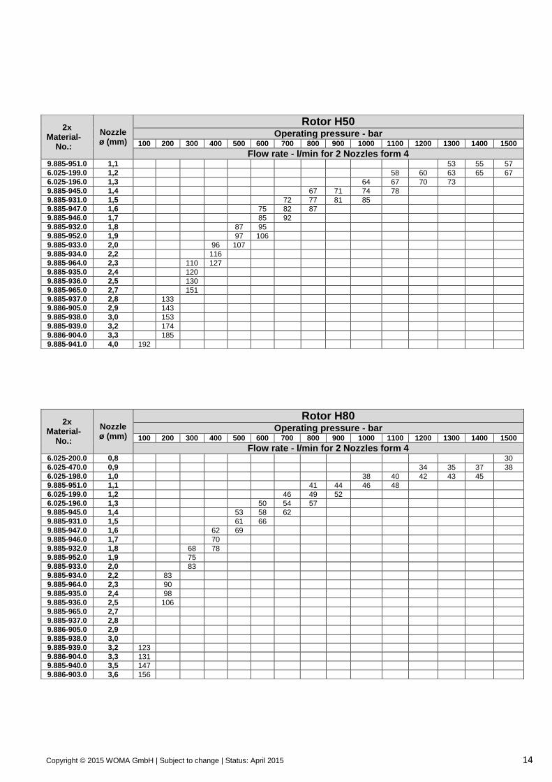
2x Material-
No.:
Nozzle ø (mm)
Rotor H50
Operating pressure - bar 100 200 300 400 500 600 700 800 900 1000 1100 1200 1300 1400 1500
Flow rate - l/min for 2 Nozzles form 4
9.885-951.0 1,1 53 55 57
6.025-199.0 1,2 58 60 63 65 67
6.025-196.0 1,3 64 67 70 73
9.885-945.0 1,4 67 71 74 78
9.885-931.0 1,5 72 77 81 85
9.885-947.0 1,6 75 82 87
9.885-946.0 1,7 85 92
9.885-932.0 1,8 87 95
9.885-952.0 1,9 97 106
9.885-933.0 2,0 96 107
9.885-934.0 2,2 116
9.885-964.0 2,3 110 127
9.885-935.0 2,4 120
9.885-936.0 2,5 130
9.885-965.0 2,7 151
9.885-937.0 2,8 133
9.886-905.0 2,9 143
9.885-938.0 3,0 153
9.885-939.0 3,2 174
9.886-904.0 3,3 185
9.885-941.0 4,0 192
2x Material-
No.:
Nozzle ø (mm)
Rotor H80 Operating pressure - bar
100 200 300 400 500 600 700 800 900 1000 1100 1200 1300 1400 1500
Flow rate - l/min for 2 Nozzles form 4
6.025-200.0 0,8 30
6.025-470.0 0,9 34 35 37 38
6.025-198.0 1,0 38 40 42 43 45
9.885-951.0 1,1 41 44 46 48
6.025-199.0 1,2 46 49 52
6.025-196.0 1,3 50 54 57
9.885-945.0 1,4 53 58 62
9.885-931.0 1,5 61 66
9.885-947.0 1,6 62 69
9.885-946.0 1,7 70
9.885-932.0 1,8 68 78
9.885-952.0 1,9 75
9.885-933.0 2,0 83
9.885-934.0 2,2 83
9.885-964.0 2,3 90
9.885-935.0 2,4 98
9.885-936.0 2,5 106
9.885-965.0 2,7
9.885-937.0 2,8
9.886-905.0 2,9
9.885-938.0 3,0
9.885-939.0 3,2 123
9.886-904.0 3,3 131
9.885-940.0 3,5 147
9.886-903.0 3,6 156
Copyright © 2015 WOMA GmbH | Subject to change | Status: April 2015 15
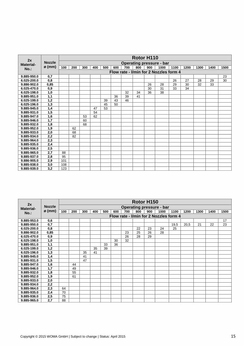
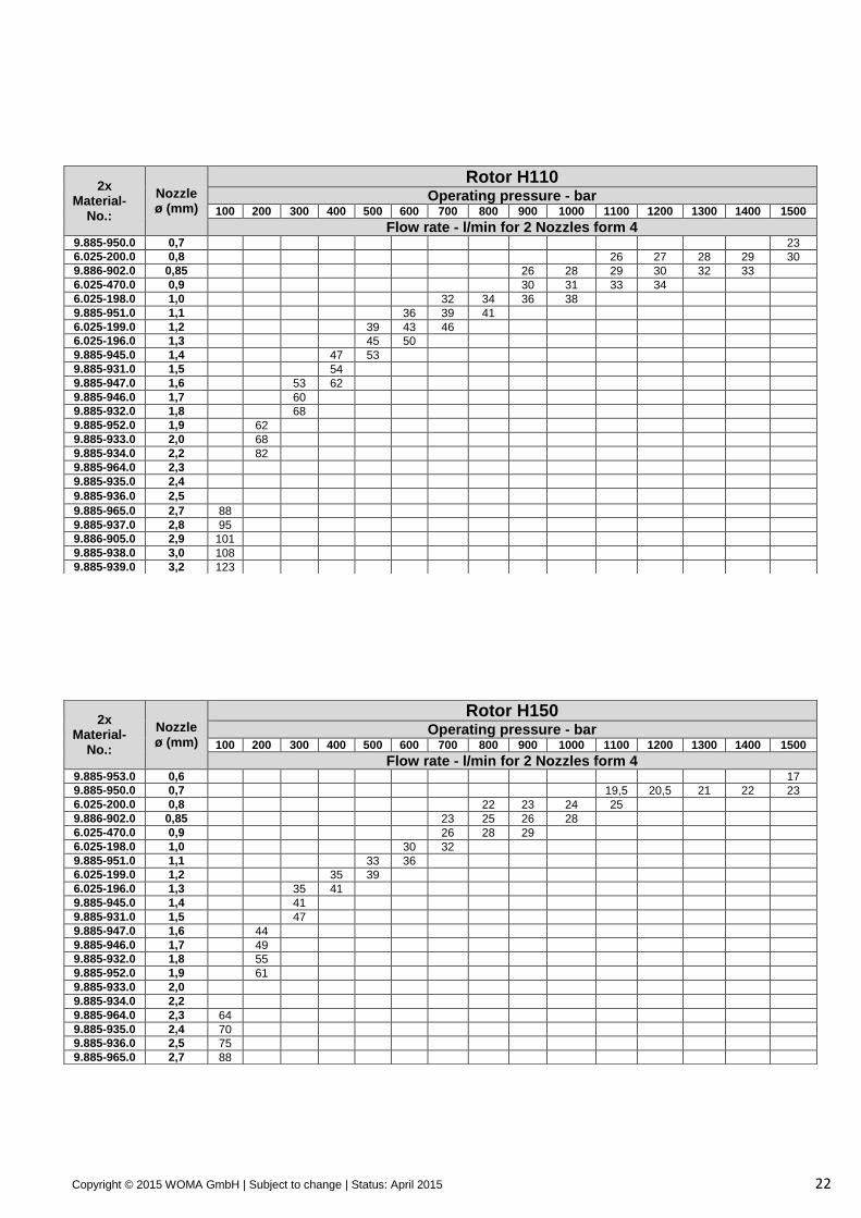
2x Material-
No.:
Nozzle ø (mm)
Rotor H110 Operating pressure - bar
100 200 300 400 500 600 700 800 900 1000 1100 1200 1300 1400 1500
Flow rate - l/min for 2 Nozzles form 4
9.885-950.0 0,7 23
6.025-200.0 0,8 26 27 28 29 30
9.886-902.0 0,85 26 28 29 30 32 33
6.025-470.0 0,9 30 31 33 34
6.025-198.0 1,0 32 34 36 38
9.885-951.0 1,1 36 39 41
6.025-199.0 1,2 39 43 46
6.025-196.0 1,3 45 50
9.885-945.0 1,4 47 53
9.885-931.0 1,5 54
9.885-947.0 1,6 53 62
9.885-946.0 1,7 60
9.885-932.0 1,8 68
9.885-952.0 1,9 62
9.885-933.0 2,0 68
9.885-934.0 2,2 82
9.885-964.0 2,3
9.885-935.0 2,4
9.885-936.0 2,5
9.885-965.0 2,7 88
9.885-937.0 2,8 95
9.886-905.0 2,9 101
9.885-938.0 3,0 108
9.885-939.0 3,2 123
2x Material-
No.:
Nozzle ø (mm)
Rotor H150 Operating pressure - bar
100 200 300 400 500 600 700 800 900 1000 1100 1200 1300 1400 1500
Flow rate - l/min for 2 Nozzles form 4
9.885-953.0 0,6 17
9.885-950.0 0,7 19,5 20,5 21 22 23
6.025-200.0 0,8 22 23 24 25
9.886-902.0 0,85 23 25 26 28
6.025-470.0 0,9 26 28 29
6.025-198.0 1,0 30 32
9.885-951.0 1,1 33 36
6.025-199.0 1,2 35 39
6.025-196.0 1,3 35 41
9.885-945.0 1,4 41
9.885-931.0 1,5 47
9.885-947.0 1,6 44
9.885-946.0 1,7 49
9.885-932.0 1,8 55
9.885-952.0 1,9 61
9.885-933.0 2,0
9.885-934.0 2,2
9.885-964.0 2,3 64
9.885-935.0 2,4 70
9.885-936.0 2,5 75
9.885-965.0 2,7 88
Copyright © 2015 WOMA GmbH | Subject to change | Status: April 2015 16
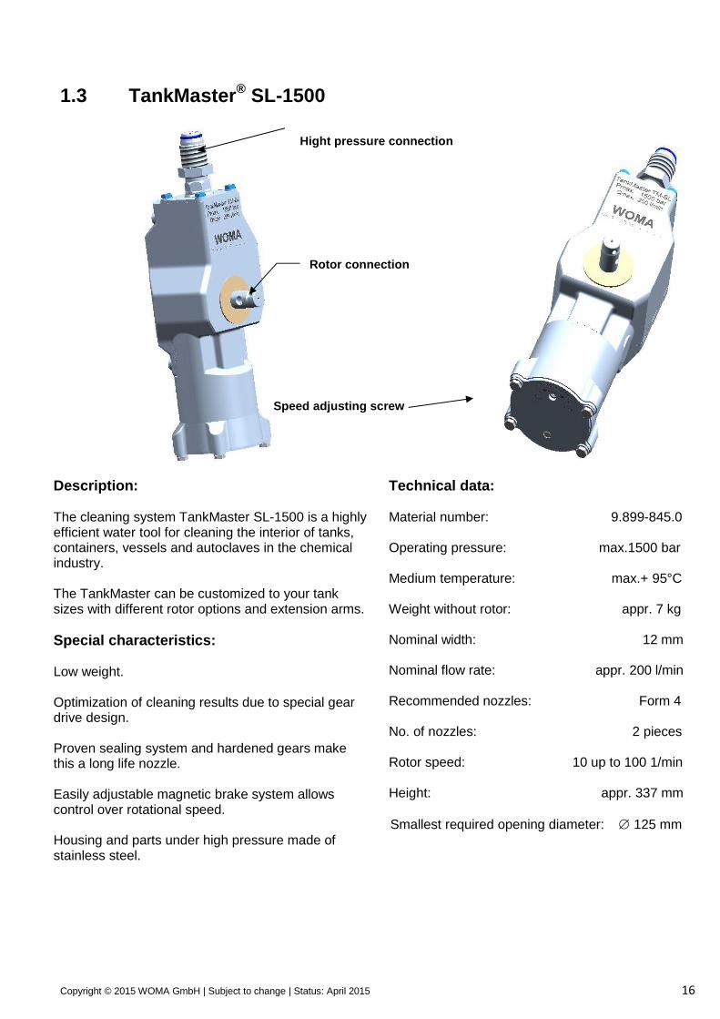
1.3 TankMaster® SL-1500
Description: The cleaning system TankMaster SL-1500 is a highly efficient water tool for cleaning the interior of tanks, containers, vessels and autoclaves in the chemical industry. The TankMaster can be customized to your tank sizes with different rotor options and extension arms.
Special characteristics: Low weight. Optimization of cleaning results due to special gear drive design. Proven sealing system and hardened gears make this a long life nozzle. Easily adjustable magnetic brake system allows control over rotational speed. Housing and parts under high pressure made of stainless steel.
Technical data: Material number: 9.899-845.0 Operating pressure: max.1500 bar Medium temperature: max.+ 95°C Weight without rotor: appr. 7 kg Nominal width: 12 mm Nominal flow rate: appr. 200 l/min Recommended nozzles: Form 4 No. of nozzles: 2 pieces Rotor speed: 10 up to 100 1/min Height: appr. 337 mm
Smallest required opening diameter: 125 mm
Speed adjusting screw
Rotor connection
Hight pressure connection
Copyright © 2015 WOMA GmbH | Subject to change | Status: April 2015 17
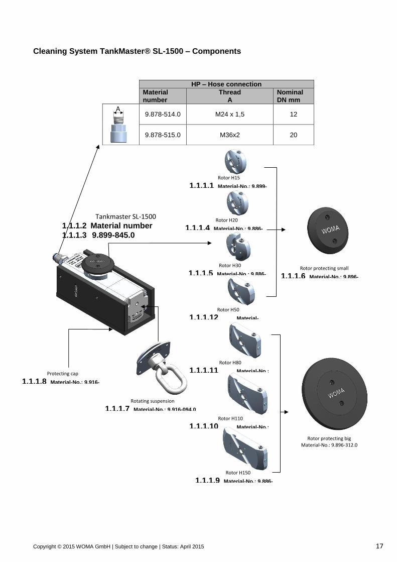
Cleaning System TankMaster® SL-1500 – Components
HP – Hose connection
Material number
Thread A
Nominal DN mm
9.878-514.0 M24 x 1,5 12
9.878-515.0 M36x2 20
Tankmaster SL-1500
1.1.1.2 Material number
1.1.1.3 9.899-845.0
Rotating suspension
1.1.1.7 Material-No.: 9.916-094.0
Protecting cap
1.1.1.8 Material-No.: 9.916-102.0
Rotor H20
1.1.1.4 Material-No.: 9.886-871.0
Rotor H30
1.1.1.5 Material-No.: 9.886-872.0
Rotor H50
1.1.1.12 Material-No.: 9.886-883.0
Rotor H80
1.1.1.11 Material-No.: 9.886-881.0
Rotor H110
1.1.1.10 Material-No.: 9.886-882.0
Rotor protecting big Material-No.: 9.896-312.0
Rotor protecting small
1.1.1.6 Material-No.: 9.896-311.0
A
Rotor H150
1.1.1.9 Material-No.: 9.886-889.0
Rotor H15
1.1.1.1 Material-No.: 9.899-840.0
Copyright © 2015 WOMA GmbH | Subject to change | Status: April 2015 18
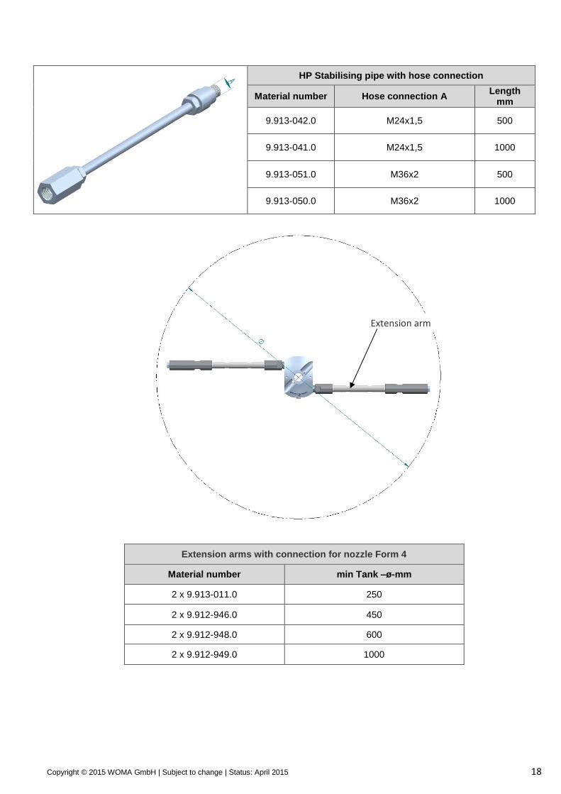
HP Stabilising pipe with hose connection
Material number Hose connection A Length
mm
9.913-042.0 M24x1,5 500
9.913-041.0 M24x1,5 1000
9.913-051.0 M36x2 500
9.913-050.0 M36x2 1000
Extension arms with connection for nozzle Form 4
Material number min Tank –ø-mm
2 x 9.913-011.0 250
2 x 9.912-946.0 450
2 x 9.912-948.0 600
2 x 9.912-949.0 1000
Extension arm
Copyright © 2015 WOMA GmbH | Subject to change | Status: April 2015 19
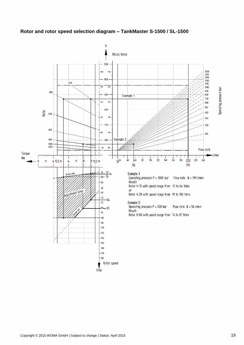
Rotor and rotor speed selection diagram – TankMaster S-1500 / SL-1500
Copyright © 2015 WOMA GmbH | Subject to change | Status: April 2015 20
Selection charts for nozzles
2x Material-
No.:
Nozzle ø (mm)
Rotor H15 Operating pressure - bar
100 200 300 400 500 600 700 800 900 1000 1100 1200 1300 1400 1500
Flow rate - l/min for 2 Nozzles form 4 9.885-952.0 1,9 168
9.885-933.0 2,0 173 180 186
9.885-934.0 2,2 193 201
9.885-964.0 2,3 200
2x Material-
No.:
Nozzle ø (mm)
Rotor H20 Operating pressure - bar
100 200 300 400 500 600 700 800 900 1000 1100 1200 1300 1400 1500
Flow rate - l/min for 2 Nozzles form 4 9.885-947.0 1,6 119
9.885-946.0 1,7 130 134
9.885-932.0 1,8 135 140 145 150
9.885-952.0 1,9 144 150 156 162 168
9.885-933.0 2,0 152 159 166 173 180
9.885-934.0 2,2 164 174 184 193
9.885-964.0 2,3 180 190 200
9.885-935.0 2,4 182 196
9.885-936.0 2,5 199
2x Material-
No.:
Nozzle ø (mm)
Rotor H30 Operating pressure - bar
100 200 300 400 500 600 700 800 900 1000 1100 1200 1300 1400 1500
Flow rate - l/min for 2 Nozzles form 4
6.025-196.0 1,3 79
9.885-945.0 1,4 85 88 91
9.885-931.0 1,5 94 98 101 105
9.885-947.0 1,6 97 102 106 111 115
9.885-946.0 1,7 104 110 115 120 125
9.885-932.0 1,8 110 117 123 129
9.885-952.0 1,9 123 130 137
9.885-933.0 2,0 128 136 144
9.885-934.0 2,2 142 154
9.885-964.0 2,3 142 155 168
9.885-935.0 2,4 155 169
9.885-936.0 2,5 168 184
9.885-965.0 2,7 175 196
9.885-937.0 2,8 188
9.885-933.0 2,9 200
9.885-938.0 3,0 187

Copyright © 2015 WOMA GmbH | Subject to change | Status: April 2015 21
2x Material-
No.:
Nozzle ø (mm)
Rotor H50
Operating pressure - bar 100 200 300 400 500 600 700 800 900 1000 1100 1200 1300 1400 1500
Flow rate - l/min for 2 Nozzles form 4
9.885-951.0 1,1 53 55 57
6.025-199.0 1,2 58 60 63 65 67
6.025-196.0 1,3 64 67 70 73
9.885-945.0 1,4 67 71 74 78
9.885-931.0 1,5 72 77 81 85
9.885-947.0 1,6 75 82 87
9.885-946.0 1,7 85 92
9.885-932.0 1,8 87 95
9.885-952.0 1,9 97 106
9.885-933.0 2,0 96 107
9.885-934.0 2,2 116
9.885-964.0 2,3 110 127
9.885-935.0 2,4 120
9.885-936.0 2,5 130
9.885-965.0 2,7 151
9.885-937.0 2,8 133
9.886-905.0 2,9 143
9.885-938.0 3,0 153
9.885-939.0 3,2 174
9.886-904.0 3,3 185
9.885-941.0 4,0 192
2x Material-
No.:
Nozzle ø (mm)
Rotor H80 Operating pressure - bar
100 200 300 400 500 600 700 800 900 1000 1100 1200 1300 1400 1500
Flow rate - l/min for 2 Nozzles form 4
6.025-200.0 0,8 30
6.025-470.0 0,9 34 35 37 38
6.025-198.0 1,0 38 40 42 43 45
9.885-951.0 1,1 41 44 46 48
6.025-199.0 1,2 46 49 52
6.025-196.0 1,3 50 54 57
9.885-945.0 1,4 53 58 62
9.885-931.0 1,5 61 66
9.885-947.0 1,6 62 69
9.885-946.0 1,7 70
9.885-932.0 1,8 68 78
9.885-952.0 1,9 75
9.885-933.0 2,0 83
9.885-934.0 2,2 83
9.885-964.0 2,3 90
9.885-935.0 2,4 98
9.885-936.0 2,5 106
9.885-965.0 2,7
9.885-937.0 2,8
9.886-905.0 2,9
9.885-938.0 3,0
9.885-939.0 3,2 123
9.886-904.0 3,3 131
9.885-940.0 3,5 147
9.886-903.0 3,6 156
Copyright © 2015 WOMA GmbH | Subject to change | Status: April 2015 22
2x Material-
No.:
Nozzle ø (mm)
Rotor H110 Operating pressure - bar
100 200 300 400 500 600 700 800 900 1000 1100 1200 1300 1400 1500
Flow rate - l/min for 2 Nozzles form 4
9.885-950.0 0,7 23
6.025-200.0 0,8 26 27 28 29 30
9.886-902.0 0,85 26 28 29 30 32 33
6.025-470.0 0,9 30 31 33 34
6.025-198.0 1,0 32 34 36 38
9.885-951.0 1,1 36 39 41
6.025-199.0 1,2 39 43 46
6.025-196.0 1,3 45 50
9.885-945.0 1,4 47 53
9.885-931.0 1,5 54
9.885-947.0 1,6 53 62
9.885-946.0 1,7 60
9.885-932.0 1,8 68
9.885-952.0 1,9 62
9.885-933.0 2,0 68
9.885-934.0 2,2 82
9.885-964.0 2,3
9.885-935.0 2,4
9.885-936.0 2,5
9.885-965.0 2,7 88
9.885-937.0 2,8 95
9.886-905.0 2,9 101
9.885-938.0 3,0 108
9.885-939.0 3,2 123
2x Material-
No.:
Nozzle ø (mm)
Rotor H150 Operating pressure - bar
100 200 300 400 500 600 700 800 900 1000 1100 1200 1300 1400 1500
Flow rate - l/min for 2 Nozzles form 4
9.885-953.0 0,6 17
9.885-950.0 0,7 19,5 20,5 21 22 23
6.025-200.0 0,8 22 23 24 25
9.886-902.0 0,85 23 25 26 28
6.025-470.0 0,9 26 28 29
6.025-198.0 1,0 30 32
9.885-951.0 1,1 33 36
6.025-199.0 1,2 35 39
6.025-196.0 1,3 35 41
9.885-945.0 1,4 41
9.885-931.0 1,5 47
9.885-947.0 1,6 44
9.885-946.0 1,7 49
9.885-932.0 1,8 55
9.885-952.0 1,9 61
9.885-933.0 2,0
9.885-934.0 2,2
9.885-964.0 2,3 64
9.885-935.0 2,4 70
9.885-936.0 2,5 75
9.885-965.0 2,7 88
Copyright © 2015 WOMA GmbH | Subject to change | Status: April 2015 23
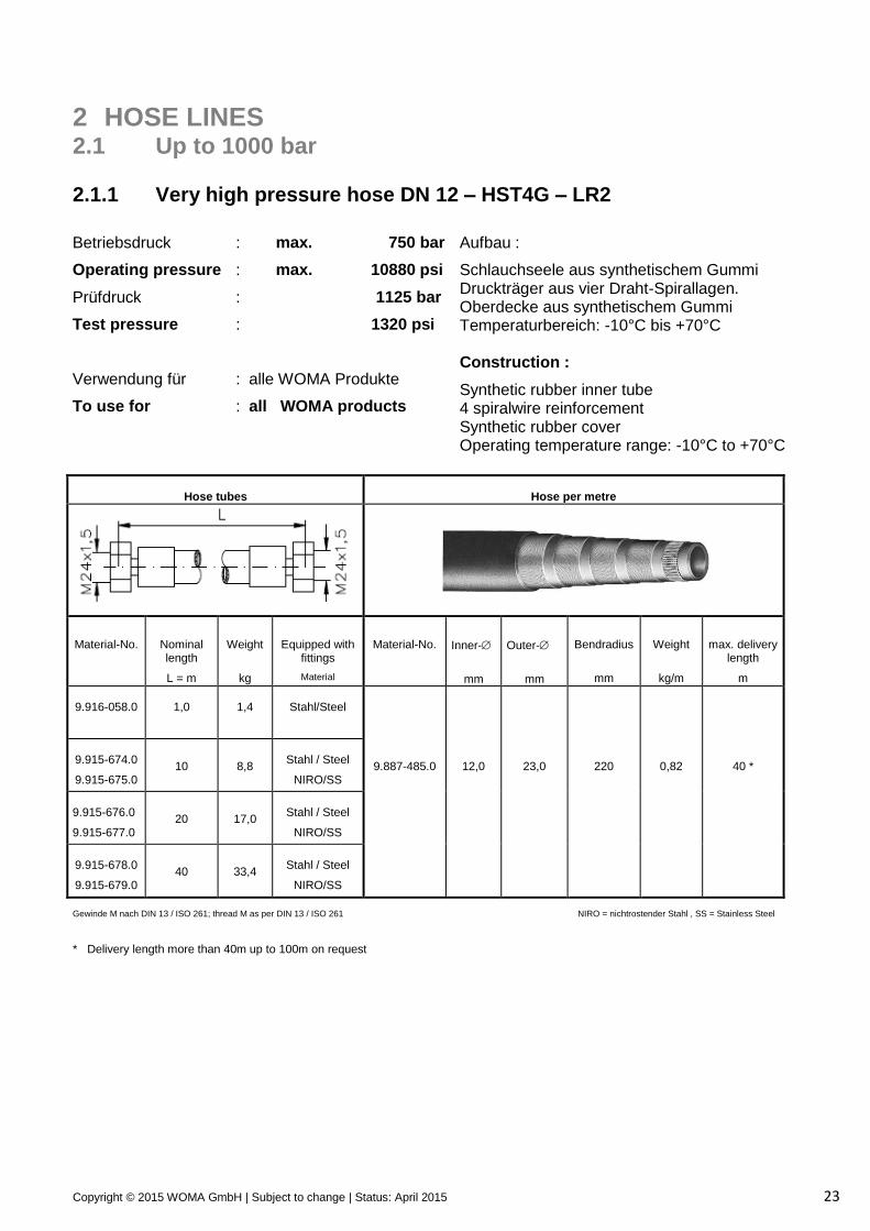
2 HOSE LINES 2.1 Up to 1000 bar 2.1.1 Very high pressure hose DN 12 – HST4G – LR2
Betriebsdruck
Operating pressure
Prüfdruck
Test pressure
Verwendung für
To use for
:
:
:
:
:
:
max. 750 bar
max. 10880 psi
1125 bar
1320 psi
alle WOMA Produkte
all WOMA products
Aufbau :
Schlauchseele aus synthetischem Gummi Druckträger aus vier Draht-Spirallagen. Oberdecke aus synthetischem Gummi Temperaturbereich: -10°C bis +70°C Construction :
Synthetic rubber inner tube 4 spiralwire reinforcement Synthetic rubber cover Operating temperature range: -10°C to +70°C
Hose tubes
Hose per metre
Material-No.
Nominal length
L = m
Weight
kg
Equipped with fittings
Material
Material-No.
Inner-
mm
Outer-
mm
Bendradius
mm
Weight
kg/m
max. delivery length
m
9.916-058.0
1,0
1,4
Stahl/Steel
9.915-674.0
9.915-675.0
10
8,8
Stahl / Steel
NIRO/SS
9.887-485.0
12,0
23,0
220
0,82
40 *
9.915-676.0
9.915-677.0
20
17,0
Stahl / Steel
NIRO/SS
9.915-678.0
9.915-679.0
40
33,4
Stahl / Steel
NIRO/SS
Gewinde M nach DIN 13 / ISO 261; thread M as per DIN 13 / ISO 261 NIRO = nichtrostender Stahl , SS = Stainless Steel
* Delivery length more than 40m up to 100m on request
Copyright © 2015 WOMA GmbH | Subject to change | Status: April 2015 24
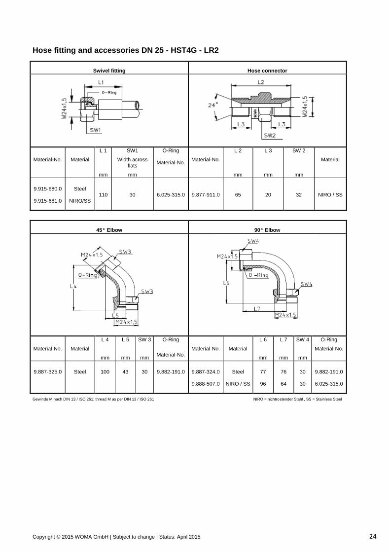
Hose fitting and accessories DN 25 - HST4G - LR2
Swivel fitting
Hose connector
Material-No.
Material
L 1
mm
SW1
Width across flats
mm
O-Ring Material-No.
Material-No.
L 2
mm
L 3
mm
SW 2
mm
Material
9.915-680.0 9.915-681.0
Steel
NIRO/SS
110
30
6.025-315.0
9.877-911.0
65
20
32
NIRO / SS
45º Elbow
90º Elbow
Material-No.
Material
L 4
mm
L 5
mm
SW 3
mm
O-Ring
Material-No.
Material-No.
Material
L 6
mm
L 7
mm
SW 4
mm
O-Ring
Material-No.
9.887-325.0
Steel
100
43
30
9.882-191.0
9.887-324.0 9.888-507.0
Steel
NIRO / SS
77
96
76
64
30
30
9.882-191.0
6.025-315.0
Gewinde M nach DIN 13 / ISO 261; thread M as per DIN 13 / ISO 261 NIRO = nichtrostender Stahl , SS = Stainless Steel
Copyright © 2015 WOMA GmbH | Subject to change | Status: April 2015 25
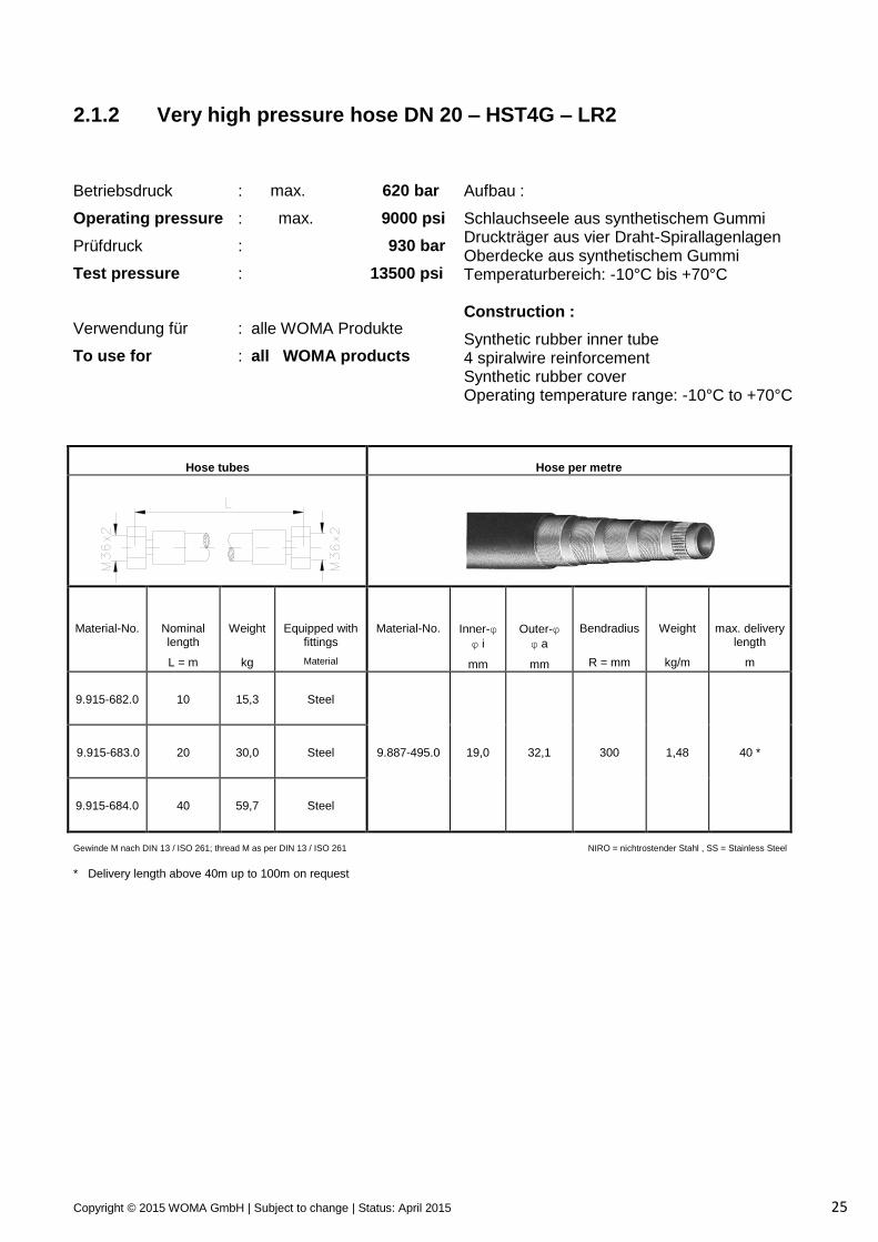
2.1.2 Very high pressure hose DN 20 – HST4G – LR2
Betriebsdruck
Operating pressure
Prüfdruck
Test pressure
Verwendung für
To use for
:
:
:
:
:
:
max. 620 bar
max. 9000 psi
930 bar
13500 psi
alle WOMA Produkte
all WOMA products
Aufbau :
Schlauchseele aus synthetischem Gummi Druckträger aus vier Draht-Spirallagenlagen Oberdecke aus synthetischem Gummi Temperaturbereich: -10°C bis +70°C Construction :
Synthetic rubber inner tube 4 spiralwire reinforcement Synthetic rubber cover Operating temperature range: -10°C to +70°C
Hose tubes
Hose per metre
Material-No.
Nominal length
L = m
Weight
kg
Equipped with fittings
Material
Material-No.
Inner-φ
φ i
mm
Outer-φ
φ a
mm
Bendradius
R = mm
Weight
kg/m
max. delivery length
m
9.915-682.0
10
15,3
Steel
9.915-683.0
20
30,0
Steel
9.887-495.0
19,0
32,1
300
1,48
40 *
9.915-684.0
40
59,7
Steel
Gewinde M nach DIN 13 / ISO 261; thread M as per DIN 13 / ISO 261 NIRO = nichtrostender Stahl , SS = Stainless Steel
* Delivery length above 40m up to 100m on request
Copyright © 2015 WOMA GmbH | Subject to change | Status: April 2015 26
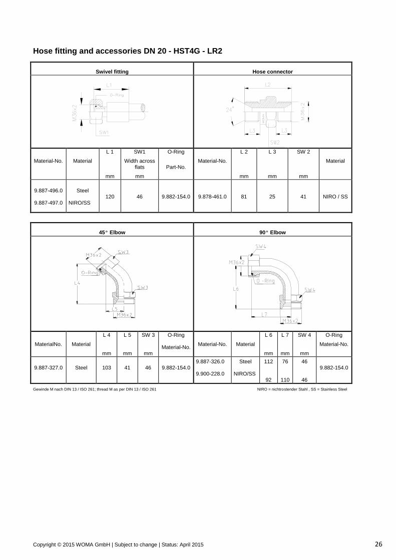
Hose fitting and accessories DN 20 - HST4G - LR2
Swivel fitting
Hose connector
Material-No.
Material
L 1
mm
SW1
Width across flats
mm
O-Ring
Part-No.
Material-No.
L 2
mm
L 3
mm
SW 2
mm
Material
9.887-496.0
9.887-497.0
Steel
NIRO/SS
120
46
9.882-154.0
9.878-461.0
81
25
41
NIRO / SS
45º Elbow
90º Elbow
MaterialNo.
Material
L 4
mm
L 5
mm
SW 3
mm
O-Ring Material-No.
Material-No.
Material
L 6
mm
L 7
mm
SW 4
mm
O-Ring
Material-No.
9.887-327.0
Steel
103
41
46
9.882-154.0
9.887-326.0 9.900-228.0
Steel NIRO/SS
112
92
76
110
46
46
9.882-154.0
Gewinde M nach DIN 13 / ISO 261; thread M as per DIN 13 / ISO 261 NIRO = nichtrostender Stahl , SS = Stainless Steel
Copyright © 2015 WOMA GmbH | Subject to change | Status: April 2015 27
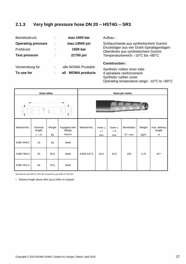
2.1.3 Very high pressure hose DN 20 – HST4G – SR3
Betriebsdruck
Operating pressure
Prüfdruck
Test pressure
Verwendung für
To use for
:
:
:
:
:
:
max.1000 bar
max.14500 psi
1500 bar
21750 psi
alle WOMA Produkte
all WOMA products
Aufbau :
Schlauchseele aus synthetischem Gummi Druckträger aus vier Draht-Spirallagenlagen Oberdecke aus synthetischem Gummi Temperaturbereich: -10°C bis +80°C Construction :
Synthetic rubber inner tube 4 spiralwire reinforcement Synthetic rubber cover Operating temperature range: -10°C to +80°C
Hose tubes
Hose per metre
Material-No.
Nominal length
L = m
Weight
kg
Equipped with fittings
Material
Material-No.
Inner-φ
φ i
mm
Outer-φ
φ a
mm
Bendradius
R = mm
Weight
kg/m
max. delivery length
m
9.887-949.0
10
18
Steel
9.887-950.0
20
35,5
Steel
9.900-147.0
19,0
32,0
250
1,75
40 *
9.887-951.0
40
70,5
Steel
Gewinde M nach DIN 13 / ISO 261; thread M as per DIN 13 / ISO 261
* Delivery length above 40m up to 100m on request
Copyright © 2015 WOMA GmbH | Subject to change | Status: April 2015 28
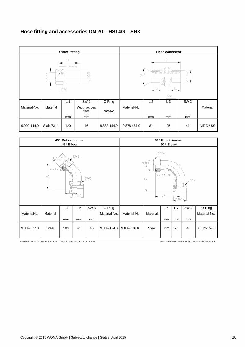
Hose fitting and accessories DN 20 – HST4G – SR3
Swivel fitting
Hose connector
Material-No.
Material
L 1
mm
SW 1
Width across flats
mm
O-Ring
Part-No.
Material-No.
L 2
mm
L 3
mm
SW 2
mm
Material
9.900-144.0
Stahl/Steel
120
46
9.882-154.0
9.878-461.0
81
25
41
NIRO / SS
45º Rohrkrümmer
45º Elbow
90º Rohrkrümmer
90º Elbow
MaterialNo.
Material
L 4
mm
L 5
mm
SW 3
mm
O-Ring
Material-No.
Material-No.
Material
L 6
mm
L 7
mm
SW 4
mm
O-Ring
Material-No.
9.887-327.0
Steel
103
41
46
9.882-154.0
9.887-326.0
Steel
112
76
46
9.882-154.0
Gewinde M nach DIN 13 / ISO 261; thread M as per DIN 13 / ISO 261 NIRO = nichtrostender Stahl , SS = Stainless Steel
Copyright © 2015 WOMA GmbH | Subject to change | Status: April 2015 29
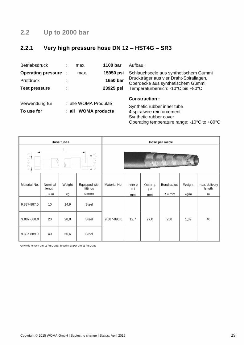
2.2 Up to 2000 bar
2.2.1 Very high pressure hose DN 12 – HST4G – SR3
Betriebsdruck
Operating pressure
Prüfdruck
Test pressure
Verwendung für
To use for
:
:
:
:
:
:
max. 1100 bar
max. 15950 psi
1650 bar
23925 psi
alle WOMA Produkte
all WOMA products
Aufbau :
Schlauchseele aus synthetischem Gummi Druckträger aus vier Draht-Spirallagen. Oberdecke aus synthetischem Gummi Temperaturbereich: -10°C bis +80°C Construction :
Synthetic rubber inner tube 4 spiralwire reinforcement Synthetic rubber cover Operating temperature range: -10°C to +80°C
Hose tubes
Hose per metre
Material-No.
Nominal length
L = m
Weight
kg
Equipped with fittings
Material
Material-No.
Inner-φ
φ i
mm
Outer-φ
φ a
mm
Bendradius
R = mm
Weight
kg/m
max. delivery length
m
9.887-887.0
10
14,9
Steel
9.887-888.0
20
28,8
Steel
9.887-890.0
12,7
27,0
250
1,39
40
9.887-889.0
40
56,6
Steel
Gewinde M nach DIN 13 / ISO 261; thread M as per DIN 13 / ISO 261
Copyright © 2015 WOMA GmbH | Subject to change | Status: April 2015 30
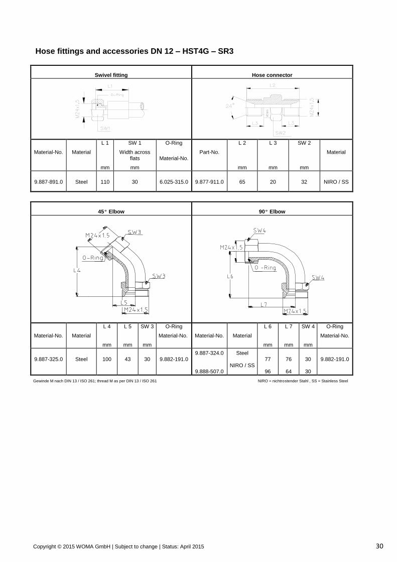
Hose fittings and accessories DN 12 – HST4G – SR3
Swivel fitting
Hose connector
Material-No.
Material
L 1
mm
SW 1
Width across flats
mm
O-Ring
Material-No.
Part-No.
L 2
mm
L 3
mm
SW 2
mm
Material
9.887-891.0
Steel
110
30
6.025-315.0
9.877-911.0
65
20
32
NIRO / SS
45º Elbow
90º Elbow
Material-No.
Material
L 4
mm
L 5
mm
SW 3
mm
O-Ring
Material-No.
Material-No.
Material
L 6
mm
L 7
mm
SW 4
mm
O-Ring
Material-No.
9.887-325.0
Steel
100
43
30
9.882-191.0
9.887-324.0
9.888-507.0
Steel
NIRO / SS
77
96
76
64
30
30
9.882-191.0
Gewinde M nach DIN 13 / ISO 261; thread M as per DIN 13 / ISO 261 NIRO = nichtrostender Stahl , SS = Stainless Steel
Copyright © 2015 WOMA GmbH | Subject to change | Status: April 2015 31
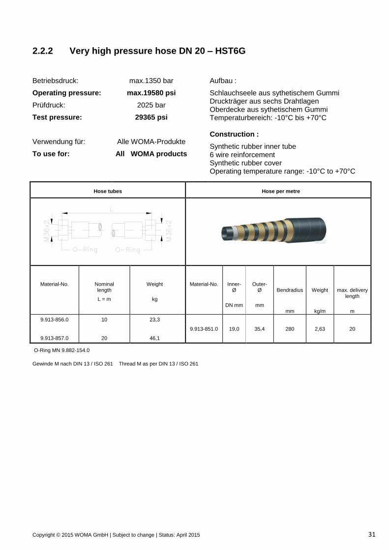
2.2.2 Very high pressure hose DN 20 – HST6G
Betriebsdruck:
Operating pressure:
Prüfdruck:
Test pressure:
Verwendung für:
To use for:
max.1350 bar
max.19580 psi
2025 bar
29365 psi
Alle WOMA-Produkte
All WOMA products
Aufbau :
Schlauchseele aus sythetischem Gummi Druckträger aus sechs Drahtlagen Oberdecke aus sythetischem Gummi Temperaturbereich: -10°C bis +70°C Construction :
Synthetic rubber inner tube 6 wire reinforcement Synthetic rubber cover Operating temperature range: -10°C to +70°C
Hose tubes
Hose per metre
Material-No.
Nominal length
L = m
Weight
kg
Material-No.
Inner- Ø
DN mm
Outer- Ø
mm
Bendradius
mm
Weight
kg/m
max. delivery
length
m
9.913-856.0 10 23,3
9.913-851.0 19,0 35,4 280 2,63 20
9.913-857.0 20 46,1
O-Ring MN 9.882-154.0
Gewinde M nach DIN 13 / ISO 261 Thread M as per DIN 13 / ISO 261
Copyright © 2015 WOMA GmbH | Subject to change | Status: April 2015 32
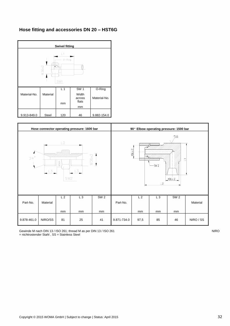
Hose fitting and accessories DN 20 – HST6G
Swivel fitting
Material-No.
Material
L 1
mm
SW 1
Width across
flats
mm
O-Ring
Material-No.
9.913-849.0
Steel
120
46
9.882-154.0
Hose connector operating pressure: 1600 bar
90º Elbow operating pressure: 1500 bar
Part-No.
Material
L 2
mm
L 3
mm
SW 2
mm
Part-No.
L 2
mm
L 3
mm
SW 2
mm
Material
9.878-461.0
NIRO/SS
81
25
41
9.871-734.0
97,5
85
46
NIRO / SS
Gewinde M nach DIN 13 / ISO 261; thread M as per DIN 13 / ISO 261 NIRO = nichtrostender Stahl , SS = Stainless Steel
Copyright © 2015 WOMA GmbH | Subject to change | Status: April 2015 33
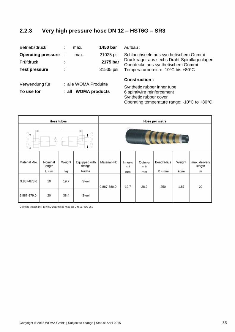
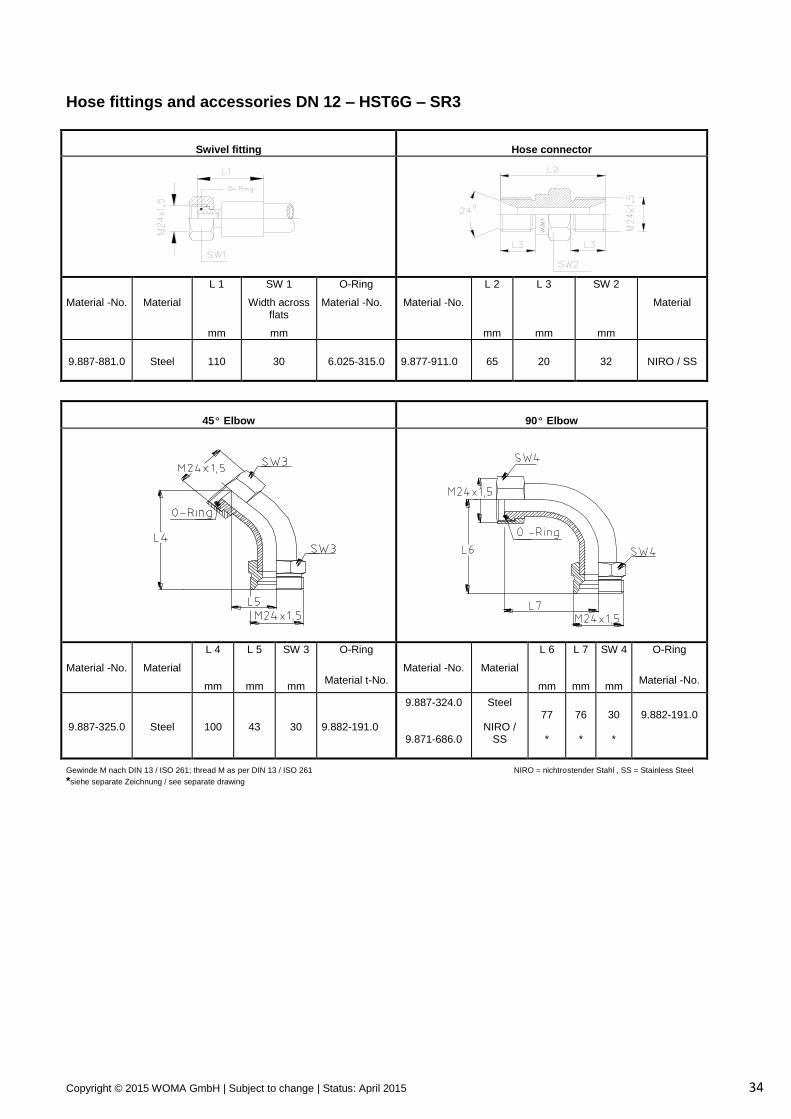
2.2.3 Very high pressure hose DN 12 – HST6G – SR3
Betriebsdruck
Operating pressure
Prüfdruck
Test pressure
Verwendung für
To use for
:
:
:
:
:
:
max. 1450 bar
max. 21025 psi
2175 bar
31535 psi
alle WOMA Produkte
all WOMA products
Aufbau :
Schlauchseele aus synthetischem Gummi Druckträger aus sechs Draht-Spirallagenlagen Oberdecke aus synthetischem Gummi Temperaturbereich: -10°C bis +80°C Construction :
Synthetic rubber inner tube 6 spiralwire reinforcement Synthetic rubber cover Operating temperature range: -10°C to +80°C
Hose tubes
Hose per metre
Material -No.
Nominal length
L = m
Weight
kg
Equipped with fittings
Material
Material -No.
Inner-φ
φ i
mm
Outer-φ
φ a
mm
Bendradius
R = mm
Weight
kg/m
max. delivery length
m
9.887-878.0
10
19,7
Steel
9.887-880.0
12,7
28,9
250
1,87
20
9.887-879.0
20
38,4
Steel
Gewinde M nach DIN 13 / ISO 261; thread M as per DIN 13 / ISO 261
Copyright © 2015 WOMA GmbH | Subject to change | Status: April 2015 34
Hose fittings and accessories DN 12 – HST6G – SR3
Swivel fitting
Hose connector
Material -No.
Material
L 1
mm
SW 1
Width across flats
mm
O-Ring
Material -No.
Material -No.
L 2
mm
L 3
mm
SW 2
mm
Material
9.887-881.0
Steel
110
30
6.025-315.0
9.877-911.0
65
20
32
NIRO / SS
45º Elbow
90º Elbow
Material -No.
Material
L 4
mm
L 5
mm
SW 3
mm
O-Ring
Material t-No.
Material -No.
Material
L 6
mm
L 7
mm
SW 4
mm
O-Ring
Material -No.
9.887-325.0
Steel
100
43
30
9.882-191.0
9.887-324.0
9.871-686.0
Steel
NIRO / SS
77 *
76 *
30 *
9.882-191.0
Gewinde M nach DIN 13 / ISO 261; thread M as per DIN 13 / ISO 261 NIRO = nichtrostender Stahl , SS = Stainless Steel
*siehe separate Zeichnung / see separate drawing
Copyright © 2015 WOMA GmbH | Subject to change | Status: April 2015 35
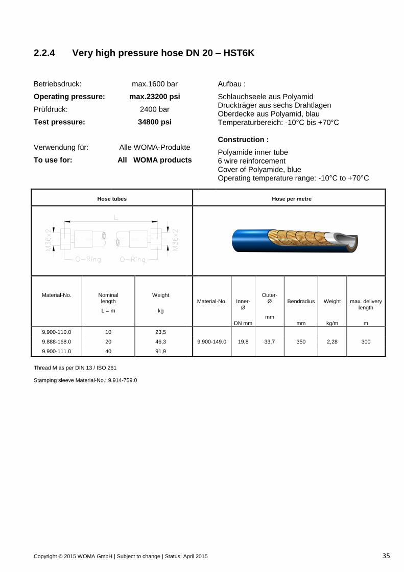
2.2.4 Very high pressure hose DN 20 – HST6K
Betriebsdruck:
Operating pressure:
Prüfdruck:
Test pressure:
Verwendung für:
To use for:
max.1600 bar
max.23200 psi
2400 bar
34800 psi
Alle WOMA-Produkte
All WOMA products
Aufbau :
Schlauchseele aus Polyamid Druckträger aus sechs Drahtlagen Oberdecke aus Polyamid, blau Temperaturbereich: -10°C bis +70°C Construction :
Polyamide inner tube 6 wire reinforcement Cover of Polyamide, blue Operating temperature range: -10°C to +70°C
Hose tubes
Hose per metre
Material-No.
Nominal length
L = m
Weight
kg
Material-No.
Inner- Ø
DN mm
Outer- Ø
mm
Bendradius
mm
Weight
kg/m
max. delivery
length
m
9.900-110.0 10 23,5
9.888-168.0 20 46,3 9.900-149.0 19,8 33,7 350 2,28 300
9.900-111.0 40 91,9
Thread M as per DIN 13 / ISO 261 Stamping sleeve Material-No.: 9.914-759.0
Copyright © 2015 WOMA GmbH | Subject to change | Status: April 2015 36
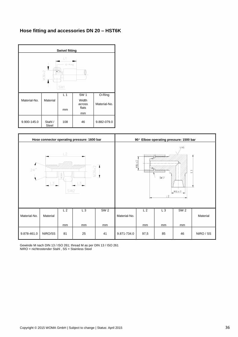
Hose fitting and accessories DN 20 – HST6K
Swivel fitting
Material-No.
Material
L 1
mm
SW 1
Width across
flats
mm
O-Ring
Material-No.
9.900-145.0
Stahl / Steel
108
46
9.882-079.0
Hose connector operating pressure: 1600 bar
90º Elbow operating pressure: 1500 bar
Material-No.
Material
L 2
mm
L 3
mm
SW 2
mm
Material-No.
L 2
mm
L 3
mm
SW 2
mm
Material
9.878-461.0
NIRO/SS
81
25
41
9.871-734.0
97,5
85
46
NIRO / SS
Gewinde M nach DIN 13 / ISO 261; thread M as per DIN 13 / ISO 261 NIRO = nichtrostender Stahl , SS = Stainless Steel
Copyright © 2015 WOMA GmbH | Subject to change | Status: April 2015 37
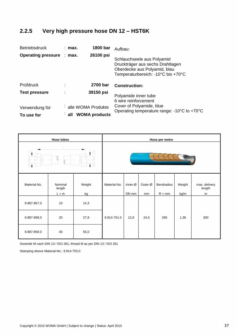
2.2.5 Very high pressure hose DN 12 – HST6K
Betriebsdruck
Operating pressure
Prüfdruck
Test pressure
Verwendung für
To use for
:
:
:
:
:
:
max. 1800 bar
max. 26100 psi
2700 bar
39150 psi
alle WOMA Produkte
all WOMA products
Aufbau: Schlauchseele aus Polyamid Druckträger aus sechs Drahtlagen Oberdecke aus Polyamid, blau Temperaturbereich: -10°C bis +70°C
Construction: Polyamide inner tube 6 wire reinforcement Cover of Polyamide, blue Operating temperature range: -10°C to +70°C
Hose tubes
Hose per metre
Material-No.
Nominal length
L = m
Weight
kg
Material-No.
Inner-Ø
DN mm
Outer-Ø
mm
Bendradius
R = mm
Weight
kg/m
max. delivery length
m
9.887-857.0
10
14,3
9.887-858.0
20
27,8
9.914-751.0
12,8
24,5
290
1,36
300
9.887-859.0
40
55,0
Gewinde M nach DIN 13 / ISO 261; thread M as per DIN 13 / ISO 261 Stamping sleeve Material-No.: 9.914-753.0
Copyright © 2015 WOMA GmbH | Subject to change | Status: April 2015 38
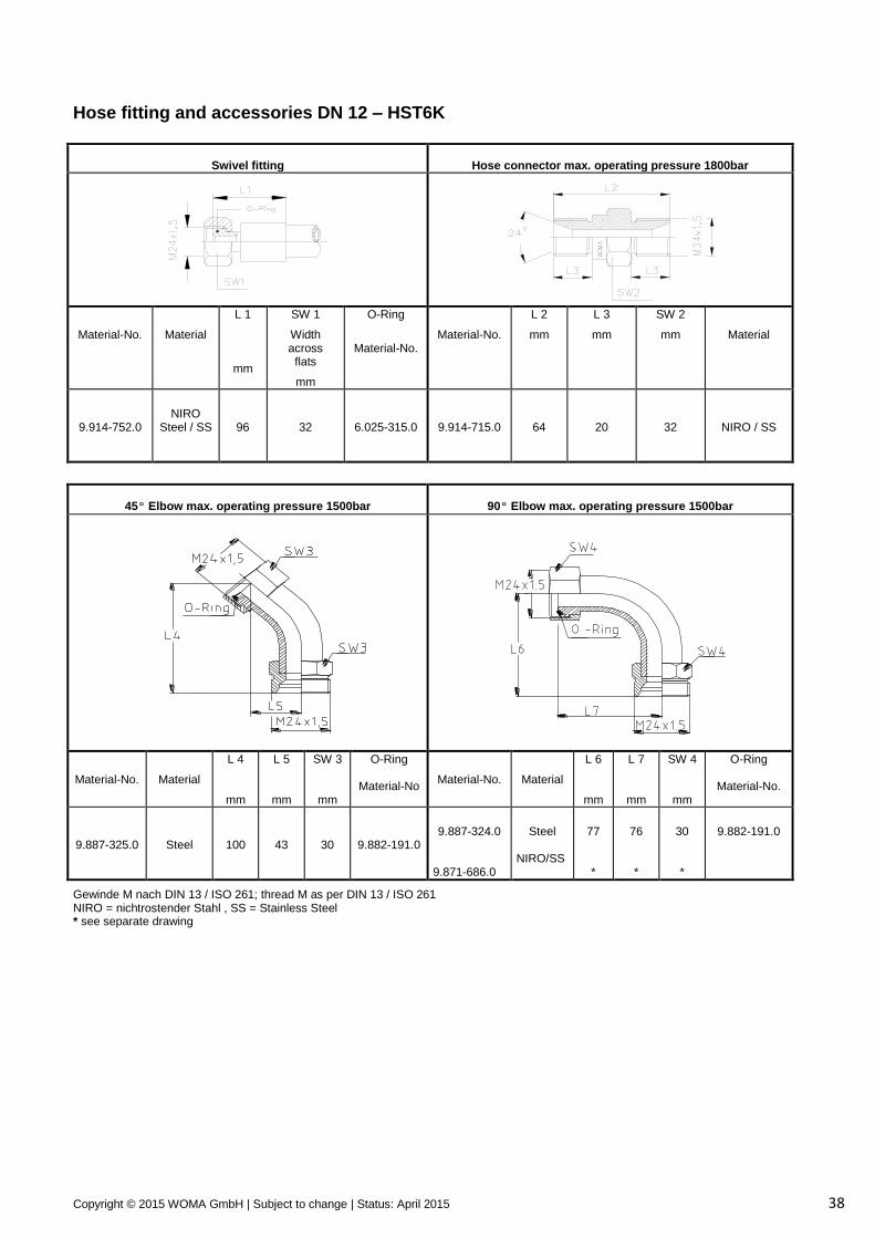
Hose fitting and accessories DN 12 – HST6K
Swivel fitting
Hose connector max. operating pressure 1800bar
Material-No.
Material
L 1
mm
SW 1
Width across
flats
mm
O-Ring
Material-No.
Material-No.
L 2
mm
L 3
mm
SW 2
mm
Material
9.914-752.0
NIRO
Steel / SS
96
32
6.025-315.0
9.914-715.0
64
20
32
NIRO / SS
45º Elbow max. operating pressure 1500bar
90º Elbow max. operating pressure 1500bar
Material-No.
Material
L 4
mm
L 5
mm
SW 3
mm
O-Ring
Material-No
Material-No.
Material
L 6
mm
L 7
mm
SW 4
mm
O-Ring
Material-No.
9.887-325.0
Steel
100
43
30
9.882-191.0
9.887-324.0
9.871-686.0
Steel
NIRO/SS
77 *
76 *
30 *
9.882-191.0
Gewinde M nach DIN 13 / ISO 261; thread M as per DIN 13 / ISO 261 NIRO = nichtrostender Stahl , SS = Stainless Steel * see separate drawing
Copyright © 2015 WOMA GmbH | Subject to change | Status: April 2015 39
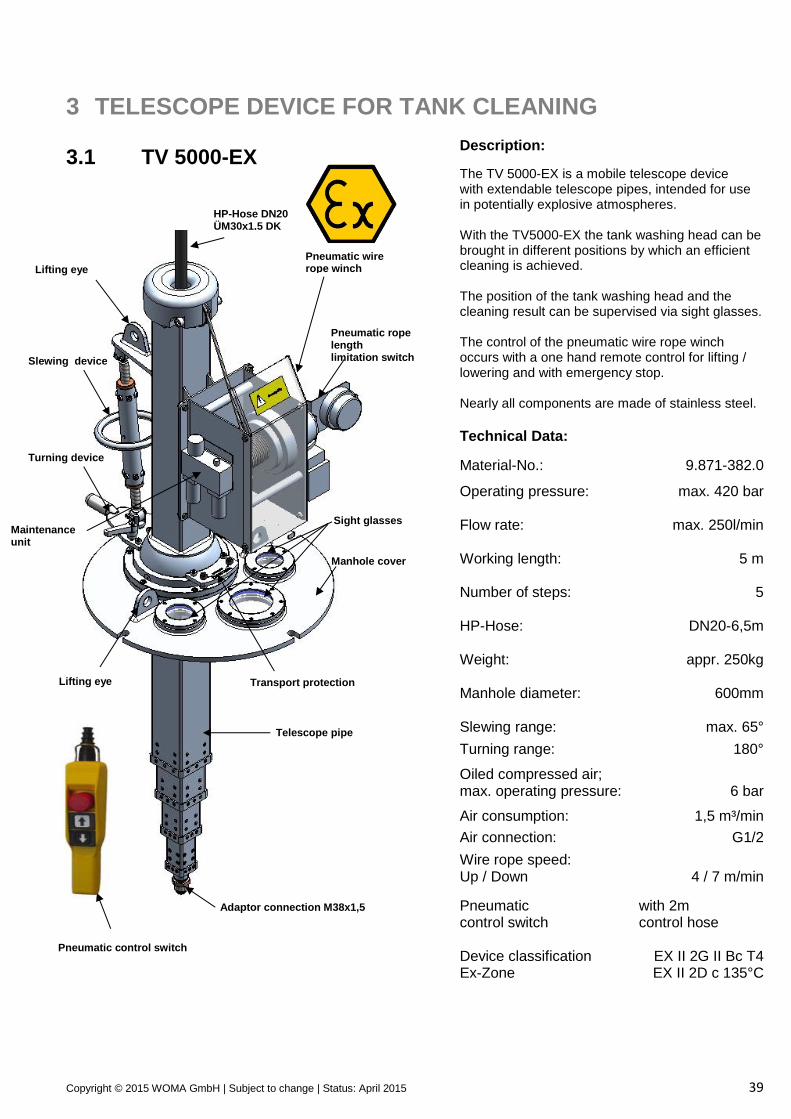
3 TELESCOPE DEVICE FOR TANK CLEANING 3.1 TV 5000-EX
Description:
The TV 5000-EX is a mobile telescope device with extendable telescope pipes, intended for use in potentially explosive atmospheres. With the TV5000-EX the tank washing head can be brought in different positions by which an efficient cleaning is achieved. The position of the tank washing head and the cleaning result can be supervised via sight glasses. The control of the pneumatic wire rope winch occurs with a one hand remote control for lifting / lowering and with emergency stop. Nearly all components are made of stainless steel.
Technical Data:
Material-No.: 9.871-382.0
Operating pressure: Flow rate:
max. 420 bar
max. 250l/min Working length: Number of steps:
5 m
5
HP-Hose:
DN20-6,5m
Weight:
appr. 250kg
Manhole diameter: 600mm
Slewing range: max. 65°
Turning range: 180°
Oiled compressed air; max. operating pressure:
6 bar
Air consumption: 1,5 m³/min
Air connection: G1/2
Wire rope speed: Up / Down
4 / 7 m/min
Pneumatic control switch
with 2m control hose
Device classification Ex-Zone
EX II 2G II Bc T4 EX II 2D c 135°C
Slewing device
Turning device
Manhole cover
Sight glasses
Pneumatic rope length limitation switch
Pneumatic wire rope winch
Lifting eye
Lifting eye
Telescope pipe
Transport protection
Adaptor connection M38x1,5
HP-Hose DN20 ÜM30x1,5 DK
Maintenance unit
Pneumatic control switch
Copyright © 2015 WOMA GmbH | Subject to change | Status: April 2015 40
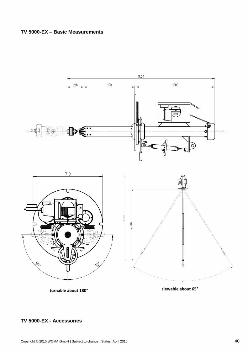
TV 5000-EX – Basic Measurements
TV 5000-EX - Accessories
turnable about 180° slewable about 65°
Copyright © 2015 WOMA GmbH | Subject to change | Status: April 2015 41
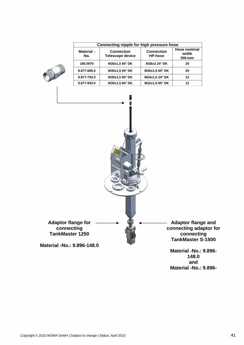
Connecting nipple for high pressure hose
Material -No.
Connection Telescope device
Connection HP-hose
Hose nominal width
DN-mm
180.0970 M30x1,5 60° DK M36x2 24° DK 20
9.877-685.0 M30x1,5 60° DK M30x1,5 60° DK 20
9.877-793.0 M30x1,5 60° DK M24x1,5 24° DK 12
9.877-933.0 M30x1,5 60° DK M22x1,5 60° DK 12
Adaptor flange for connecting
TankMaster 1250
Material -No.: 9.896-148.0
Adaptor flange and connecting adaptor for
connecting TankMaster S-1500
Material -No.: 9.896-
148.0 and
Material -No.: 9.896-356.0
Copyright © 2015 WOMA GmbH | Subject to change | Status: April 2015 42
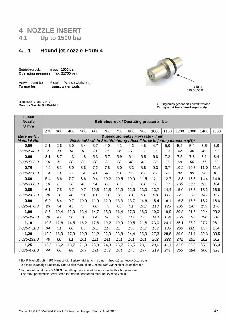
4 NOZZLE INSERT 4.1 Up to 1500 bar 4.1.1 Round jet nozzle Form 4
Betriebsdruck: max. 1500 bar Operating pressure: max. 21750 psi
O-Ring 6.025-168.0
O-Ring muss gesondert bestellt werden. O-ring must be ordered separately.
Verwendung bei: Pistolen, Wasserwerkzeuge To use for: guns, water tools
Blinddüse 9.885-944.0 Dummy Nozzle 9.885-944.0
Düsen Nozzle
mm
Betriebsdruck / Operating pressure - bar -
200 300 400 500 600 700 750 800 900 1000 1100 1200 1300 1400 1500
Material-Nr. Material-No.
Düsendurchsatz / Flow rate - l/min Rückstoßkraft in Strahlrichtung / Recoil force in jetting direction /(N)*
0,50 2,1 2,6 3,0 3,4 3,7 4,0 4,1 4,2 4,5 4,7 5,0 5,2 5,4 5,6 5,8
9.885-948.0 7 11 14 18 21 25 26 28 32 35 39 42 46 49 53
0,60 3,1 3,7 4,3 4,8 5,3 5,7 5,9 6,1 6,5 6,8 7,2 7,5 7,8 8,1 8,4
9.885-953.0 10 15 20 25 30 35 38 40 45 50 55 60 66 71 76
0,70 4,2 5,1 5,9 6,6 7,2 7,8 8,0 8,3 8,8 9,3 9,7 10,2 10,6 11,0 11,4
9.885-950.0 14 21 27 34 41 48 51 55 62 69 75 82 89 96 103
0,80 5,4 6,6 7,7 8,6 9,4 10,2 10,5 10,9 11,5 12,1 12,7 13,3 13,8 14,4 14,9
6.025-200.0 18 27 36 45 54 63 67 72 81 90 99 108 117 125 134
0,85 6,1 7,5 8,7 9,7 10,6 11,5 11,9 12,3 13,0 13,7 14,4 15,0 15,6 16,2 16,8
9.886-902.0 20 30 40 51 61 71 76 81 91 101 111 121 132 142 152
0,90 6,9 8,4 9,7 10,9 11,9 12,9 13,3 13,7 14,6 15,4 16,1 16,8 17,5 18,2 18,8
6.025-470.0 23 34 45 57 68 79 85 91 102 113 125 136 147 159 170
1,00 8,5 10,4 12,0 13,4 14,7 15,9 16,4 17,0 18,0 19,0 19,9 20,8 21,6 22,4 23,2
6.025-198.0 28 42 56 70 84 98 105 112 126 140 154 168 182 196 210
1,10 10,3 12,6 14,5 16,2 17,8 19,2 19,9 20,5 21,8 23,0 24,1 25,1 26,2 27,2 28,1
9.885-951.0 34 51 68 85 102 119 127 136 152 169 186 203 220 237 254
1,20 12,2 15,0 17,3 19,3 21,2 22,9 23,8 24,4 25,9 27,3 28,6 29,9 31,1 32,3 33,5
6.025-199.0 40 60 81 101 121 141 151 161 181 202 222 242 262 282 302
1,25 13,3 16,2 18,7 21,0 23,0 24,8 25,7 26,5 28,1 29,6 31,1 32,5 33,8 35,1 36,3
6.025-471.0 44 66 88 109 131 153 164 175 197 219 241 263 284 306 328
* Bei Rückstoßkraft > 150 N muss die Spritzeinrichtung mit einer Körperstütze ausgerüstet sein.
Die max. zulässige Rückstoßkraft für den manuellen Einsatz darf 250 N nicht überschreiten.
* In case of recoil force > 150 N the jetting device must be equipped with a body support.
The max. permissible recoil force for manual operation must not exceed 250 N.

Copyright © 2015 WOMA GmbH | Subject to change | Status: April 2015 43
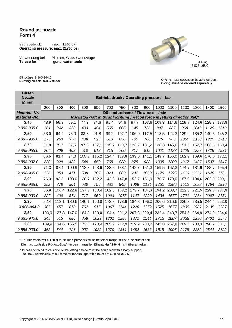
Round jet nozzle Form 4 Betriebsdruck: max. 1500 bar Operating pressure: max. 21750 psi
O-Ring 6.025-168.0
O-Ring muss gesondert bestellt werden. O-ring must be ordered separately.
Verwendung bei: Pistolen, Wasserwerkzeuge To use for: guns, water tools
Blinddüse 9.885-944.0 Dummy Nozzle 9.885-944.0
Düsen Nozzle
mm
Betriebsdruck / Operating pressure - bar -
200 300 400 500 600 700 750 800 900 1000 1100 1200 1300 1400 1500
Material -Nr. Material -No.
Düsendurchsatz / Flow rate - l/min Rückstoßkraft in Strahlrichtung / Recoil force in jetting direction /(N)*
1,30 14,3 17,6 20,3 22,7 24,8 26,8 27,8 28,7 30,4 32,1 33,6 35,1 36,5 37,9 39,3
6.025-196.0 47 71 95 118 142 166 177 189 213 237 260 284 308 331 355
1,40 16,6 20,4 23,5 26,3 28,8 31,1 32,2 33,3 35,3 37,2 39,0 40,7 42,4 44,0 45,5
9.885-945.0 55 82 110 137 165 192 206 220 247 274 302 329 357 384 412
1,50 19,1 23,4 27,0 30,2 33,1 35,7 37,0 38,2 40,5 42,7 44,8 46,8 48,7 50,5 52,3
9.885-931.0 63 95 126 158 189 221 236 252 284 315 347 378 410 441 473
1,60 21,7 26,6 30,7 34,4 37,6 40,6 42,1 43,4 46,1 48,6 50,9 53,2 55,4 57,5 59,5
9.885-947.0 72 108 143 179 215 251 269 287 323 358 394 430 466 502 538
1,70 24,5 30,0 34,7 38,8 42,5 45,9 45,5 49,0 52,0 54,8 57,5 60,0 62,5 64,9 67,1
9.885-946.0 81 121 162 202 243 283 304 324 364 405 445 486 526 567 607
1,80 27,5 33,7 38,9 43,5 47,6 51,4 53,2 55,0 58,3 61,5 64,5 67,3 70,1 72,7 75,3
9.885-932.0 91 136 181 227 272 318 340 363 408 454 499 544 590 635 681
1,90 30,6 37,5 43,3 48,4 53,0 57,3 59,3 61,2 65,0 68,5 71,8 75,0 78,1 81,0 83,9
9.885-952.0 101 152 202 253 303 354 379 404 455 505 556 607 657 708 758
2,00 33,9 41,6 48,0 53,6 58,8 63,5 65,7 67,9 72,0 75,9 79,6 83,1 86,5 89,8 92,9
9.885-933.0 112 168 224 280 336 392 420 448 504 560 616 672 728 784 840
2,20 41,1 50,3 58,1 64,9 71,1 76,8 79,5 82,1 87,1 91,8 96,3 100,6 104,7 108,6 112,4
9.885-934.0 136 203 271 339 407 474 508 542 610 678 746 813 881 949 1017
2,30 44,9 55,0 63,5 71,0 77,7 83,9 86,9 89,7 95,2 100,3 105,2 109,9 114,4 118,7 122,9
9.885-964.0 148 222 296 370 444 519 556 593 667 741 815 889 963 1037 1111
* Bei Rückstoßkraft > 150 N muss die Spritzeinrichtung mit einer Körperstütze ausgerüstet sein.
Die max. zulässige Rückstoßkraft für den manuellen Einsatz darf 250 N nicht überschreiten.
* In case of recoil force > 150 N the jetting device must be equipped with a body support. The max. permissible recoil force for manual operation must not exceed 250 N.
Copyright © 2015 WOMA GmbH | Subject to change | Status: April 2015 44
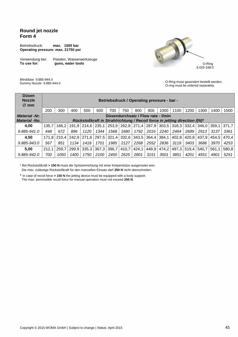
Round jet nozzle Form 4 Betriebsdruck: max. 1500 bar Operating pressure: max. 21750 psi
O-Ring 6.025-168.0
O-Ring muss gesondert bestellt werden. O-ring must be ordered separately.
Verwendung bei: Pistolen, Wasserwerkzeuge To use for: guns, water tools
Blinddüse 9.885-944.0 Dummy Nozzle 9.885-944.0
Düsen Nozzle
mm
Betriebsdruck / Operating pressure - bar -
200 300 400 500 600 700 750 800 900 1000 1100 1200 1300 1400 1500
Material -Nr. Material -No.
Düsendurchsatz / Flow rate - l/min Rückstoßkraft in Strahlrichtung / Recoil force in jetting direction /(N)*
2,40 48,9 59,8 69,1 77,3 84,6 91,4 94,6 97,7 103,6 109,3 114,6 119,7 124,6 129,3 133,8
9.885-935.0 161 242 323 403 484 565 605 645 726 807 887 968 1049 1129 1210
2,50 53,0 64,9 75,0 83,8 91,8 99,2 102,7 106,0 112,5 118,5 124,3 129,9 135,2 140,3 145,2
9.885-936.0 175 263 350 438 525 613 656 700 788 875 963 1050 1138 1225 1313
2,70 61,8 75,7 87,5 97,8 107,1 115,7 119,7 123,7 131,2 138,3 145,0 151,5 157,7 163,6 169,4
9.885-965.0 204 306 408 510 612 715 766 817 919 1021 1123 1225 1327 1429 1531
2,80 66,5 81,4 94,0 105,2 115,2 124,4 128,8 133,0 141,1 148,7 156,0 162,9 169,6 176,0 182,1
9.885-937.0 220 329 439 549 659 768 823 878 988 1098 1208 1317 1427 1537 1647
2,90 71,3 87,4 100,9 112,8 123,6 133,5 138,1 142,7 151,3 159,5 167,3 174,7 181,9 188,7 195,4
9.886-905.0 236 353 471 589 707 824 883 942 1060 1178 1295 1413 1531 1649 1766
3,00 76,3 93,5 108,0 120,7 132,2 142,8 147,8 152,7 161,9 170,7 179,0 187,0 194,6 202,0 209,1
9.885-938.0 252 378 504 630 756 882 945 1008 1134 1260 1386 1512 1638 1764 1890
3,20 86,9 106,4 122,8 137,3 150,4 162,5 168,2 173,7 184,3 194,2 203,7 212,8 221,5 229,8 237,9
9.885-939.0 287 430 574 717 860 1004 1075 1147 1290 1434 1577 1721 1864 2007 2151
3,30 92,4 113,1 130,6 146,1 160,0 172,8 178,9 184,8 196,0 206,6 216,6 226,3 235,5 244,4 253,0
9.886-904.0 305 457 610 762 915 1067 1144 1220 1372 1525 1677 1830 1982 2135 2287
3,50 103,9 127,3 147,0 164,3 180,0 194,4 201,2 207,8 220,4 232,4 243,7 254,5 264,9 274,9 284,6
9.885-940.0 343 515 686 858 1029 1201 1286 1372 1544 1715 1887 2058 2230 2401 2573
3,60 109,9 134,6 155,5 173,8 190,4 205,7 212,9 219,9 233,2 245,8 257,8 269,3 280,3 290,9 301,1
9.886-903.0 363 544 726 907 1089 1270 1361 1452 1633 1815 1996 2178 2359 2541 2722
* Bei Rückstoßkraft > 150 N muss die Spritzeinrichtung mit einer Körperstütze ausgerüstet sein.
Die max. zulässige Rückstoßkraft für den manuellen Einsatz darf 250 N nicht überschreiten.
* In case of recoil force > 150 N the jetting device must be equipped with a body support.
The max. permissible recoil force for manual operation must not exceed 250 N.
Copyright © 2015 WOMA GmbH | Subject to change | Status: April 2015 45
Round jet nozzle Form 4 Betriebsdruck: max. 1500 bar Operating pressure: max. 21750 psi
O-Ring 6.025-168.0
O-Ring muss gesondert bestellt werden. O-ring must be ordered separately.
Verwendung bei: Pistolen, Wasserwerkzeuge To use for: guns, water tools
Blinddüse 9.885-944.0 Dummy Nozzle 9.885-944.0
Düsen Nozzle
mm
Betriebsdruck / Operating pressure - bar -
200 300 400 500 600 700 750 800 900 1000 1100 1200 1300 1400 1500
Material -Nr. Material -No.
Düsendurchsatz / Flow rate - l/min Rückstoßkraft in Strahlrichtung / Recoil force in jetting direction /(N)*
4,00 135,7 166,2 191,9 214,6 235,1 253,9 262,8 271,4 287,9 303,5 318,3 332,4 346,0 359,1 371,7
9.885-941.0 448 672 896 1120 1344 1568 1680 1792 2016 2240 2464 2689 2913 3137 3361
4,50 171,8 210,4 242,9 271,6 297,5 321,4 332,6 343,5 364,4 384,1 402,8 420,8 437,9 454,5 470,4
9.885-943.0 567 851 1134 1418 1701 1985 2127 2268 2552 2836 3119 3403 3686 3970 4253
5,00 212,1 259,7 299,9 335,3 367,3 396,7 410,7 424,1 449,9 474,2 497,3 519,4 540,7 561,1 580,8
9.885-942.0 700 1050 1400 1750 2100 2450 2625 2801 3151 3501 3851 4201 4551 4901 5251
* Bei Rückstoßkraft > 150 N muss die Spritzeinrichtung mit einer Körperstütze ausgerüstet sein.
Die max. zulässige Rückstoßkraft für den manuellen Einsatz darf 250 N nicht überschreiten.
* In case of recoil force > 150 N the jetting device must be equipped with a body support.
The max. permissible recoil force for manual operation must not exceed 250 N.
Copyright © 2015 WOMA GmbH | Subject to change | Status: April 2015 46
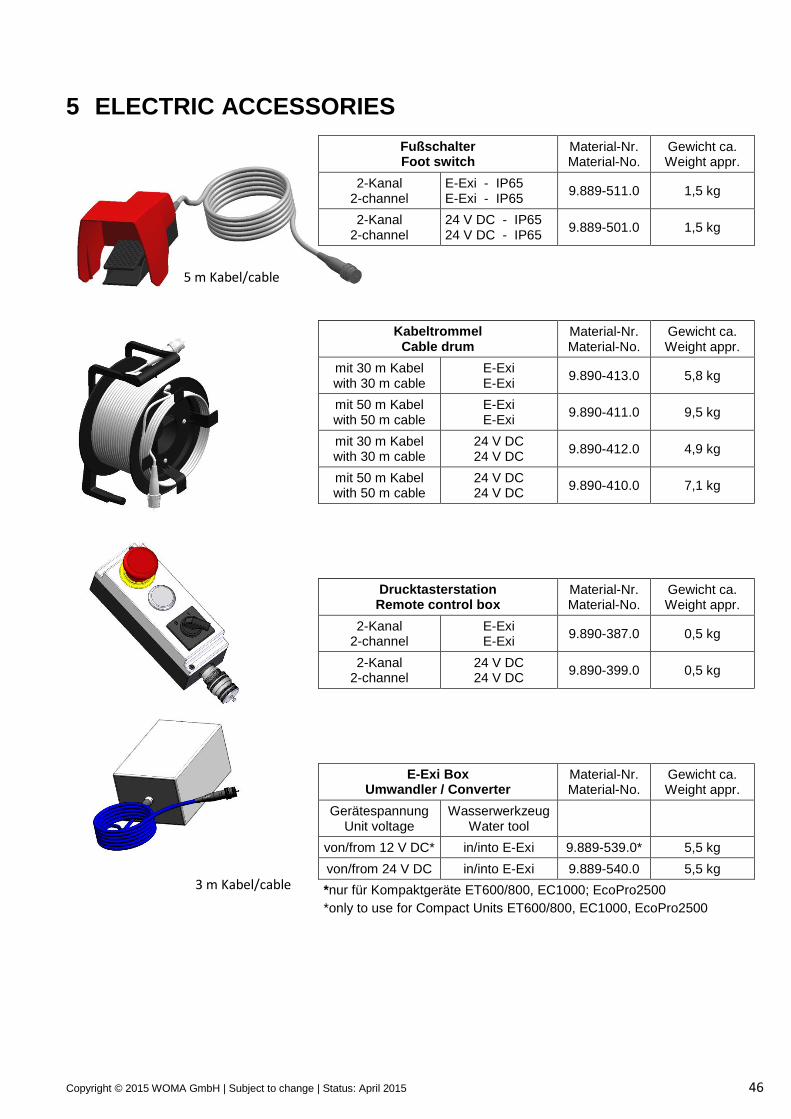
5 ELECTRIC ACCESSORIES
Fußschalter Foot switch
Material-Nr. Material-No.
Gewicht ca. Weight appr.
2-Kanal 2-channel
E-Exi - IP65 E-Exi - IP65
9.889-511.0 1,5 kg
2-Kanal 2-channel
24 V DC - IP65 24 V DC - IP65
9.889-501.0 1,5 kg
Kabeltrommel Cable drum
Material-Nr. Material-No.
Gewicht ca. Weight appr.
mit 30 m Kabel with 30 m cable
E-Exi E-Exi
9.890-413.0 5,8 kg
mit 50 m Kabel with 50 m cable
E-Exi E-Exi
9.890-411.0 9,5 kg
mit 30 m Kabel with 30 m cable
24 V DC 24 V DC
9.890-412.0 4,9 kg
mit 50 m Kabel with 50 m cable
24 V DC 24 V DC
9.890-410.0 7,1 kg
Drucktasterstation Remote control box
Material-Nr. Material-No.
Gewicht ca. Weight appr.
2-Kanal 2-channel
E-Exi E-Exi
9.890-387.0 0,5 kg
2-Kanal 2-channel
24 V DC 24 V DC
9.890-399.0 0,5 kg
E-Exi Box Umwandler / Converter
Material-Nr. Material-No.
Gewicht ca. Weight appr.
Gerätespannung Unit voltage
Wasserwerkzeug Water tool
von/from 12 V DC* in/into E-Exi 9.889-539.0* 5,5 kg
von/from 24 V DC in/into E-Exi 9.889-540.0 5,5 kg
*nur für Kompaktgeräte ET600/800, EC1000; EcoPro2500
*only to use for Compact Units ET600/800, EC1000, EcoPro2500
5 m Kabel/cable
3 m Kabel/cable
Copyright © 2015 WOMA GmbH | Subject to change | Status: April 2015 47
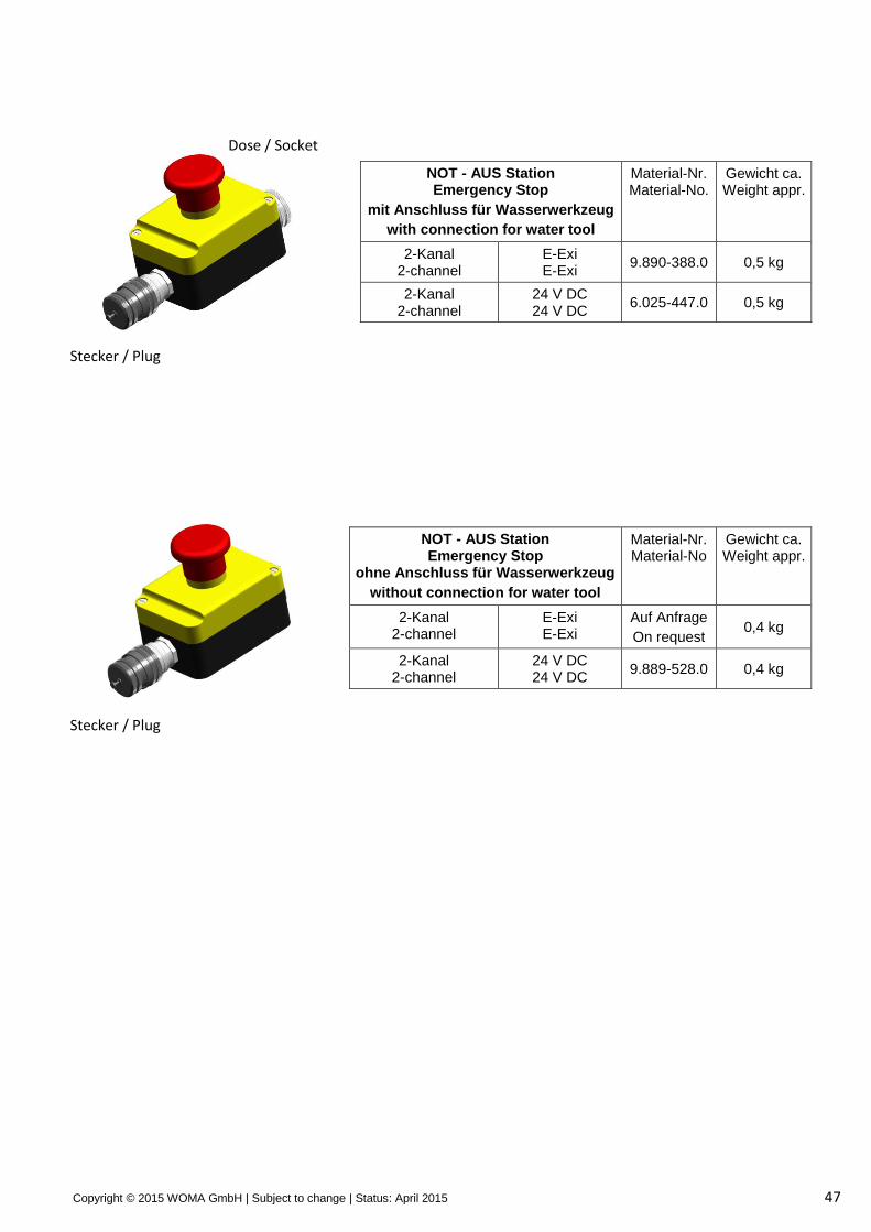
NOT - AUS Station Emergency Stop
mit Anschluss für Wasserwerkzeug
with connection for water tool
Material-Nr. Material-No.
Gewicht ca. Weight appr.
2-Kanal 2-channel
E-Exi E-Exi
9.890-388.0 0,5 kg
2-Kanal 2-channel
24 V DC 24 V DC
6.025-447.0 0,5 kg
NOT - AUS Station Emergency Stop
ohne Anschluss für Wasserwerkzeug
without connection for water tool
Material-Nr. Material-No
Gewicht ca. Weight appr.
2-Kanal 2-channel
E-Exi E-Exi
Auf Anfrage
On request 0,4 kg
2-Kanal 2-channel
24 V DC 24 V DC
9.889-528.0 0,4 kg
Stecker / Plug
Stecker / Plug
Dose / Socket
Copyright © 2015 WOMA GmbH | Subject to change | Status: April 2015 48
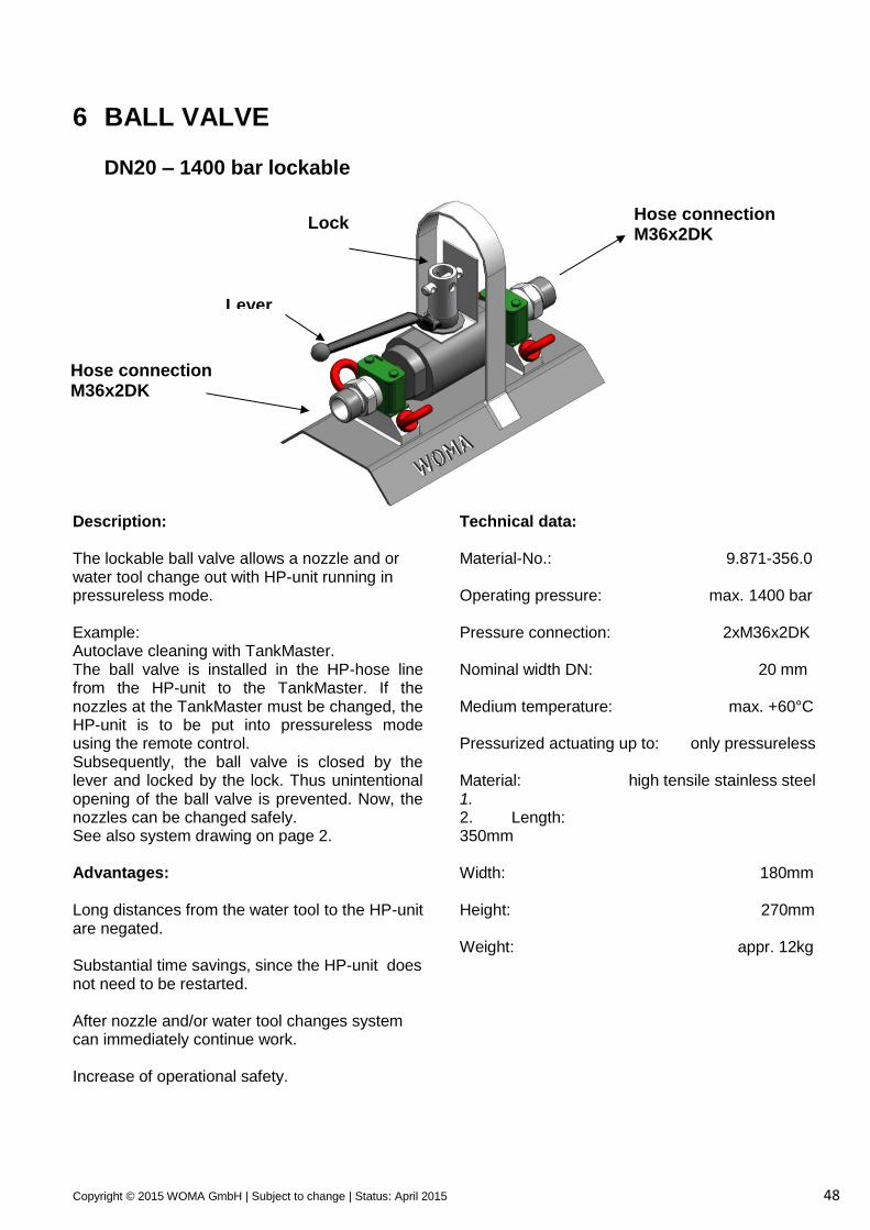
6 BALL VALVE DN20 – 1400 bar lockable
Description: The lockable ball valve allows a nozzle and or water tool change out with HP-unit running in pressureless mode. Example: Autoclave cleaning with TankMaster. The ball valve is installed in the HP-hose line from the HP-unit to the TankMaster. If the nozzles at the TankMaster must be changed, the HP-unit is to be put into pressureless mode using the remote control. Subsequently, the ball valve is closed by the lever and locked by the lock. Thus unintentional opening of the ball valve is prevented. Now, the nozzles can be changed safely. See also system drawing on page 2. Advantages: Long distances from the water tool to the HP-unit are negated. Substantial time savings, since the HP-unit does not need to be restarted. After nozzle and/or water tool changes system can immediately continue work. Increase of operational safety.
Technical data: Material-No.: 9.871-356.0 Operating pressure: max. 1400 bar Pressure connection: 2xM36x2DK Nominal width DN: 20 mm Medium temperature: max. +60°C Pressurized actuating up to: only pressureless Material: high tensile stainless steel 1. 2. Length: 350mm Width: 180mm Height: 270mm Weight: appr. 12kg
Hose connection M36x2DK to water tool
Hose connection M36x2DK from HP-unit
Lock
Lever
Copyright © 2015 WOMA GmbH | Subject to change | Status: April 2015 49
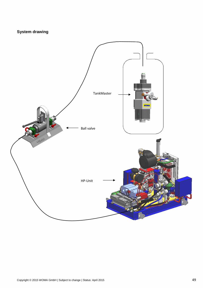
System drawing
Ball valve
TankMaster
HP-Unit
Copyright © 2015 WOMA GmbH | Subject to change | Status: April 2015 50
Contact and Support
WOMA GmbH Werthauser Str. 77 – 79 47226 Duisburg Postfach 14 18 20 47208 Duisburg Telefon +49 2065 304-0 Telefax +49 2065 304-200 E-Mail [email protected] Internet www.woma.de
Sales and Service Werthauser Str. 77 – 79 47226 Duisburg Telefon +49 2065 304-0 Telefax +49 2065 304-200 E-Mail [email protected]


![351pv.test. 20140123.pdf)vac.hu/docs/10_varosfejlesztonov.pdfUjhegyi úti- Ovodában a központi kapcsolószekrény méret]en vezetékénekjavítása Bét]eményben WOMA-s tisztítás](https://static.fdocument.pub/doc/165x107/5e602150975b7364534b1db8/351pvtest-vachudocs10varosfejlesztonovpdf-ujhegyi-ti-ovodban-a-kzponti.jpg)