wangquanfeng-200712-2
16
ASIAN JOURNAL OF CIVIL ENGINEERING (BUILDING AND HOUSING) VOL. 5, NOS 1-2 (2004) PAGES 25-40 NONLINEAR ANALYSIS OF REINFORCED CONCRETE CONTINUOUS DEEP BEAMS USING STRINGER - PANEL MODEL Q. Wang ∗1, 2 , P.C.J. Hoogenboom 2 1 Department of Civil Engineering, Huaqiao University, 362011 Quanzhou, China 2 Department of Civil Engineering, Delft University of Technology, 2600 GA Delft, The Netherlands ABSTRACT This paper describes the numerical tests for the nonlinear analysis of eight reinforced concrete (RC) deep beams. A stringer-panel model is pres ented for the nonlinear analysis of the deep be ams. Cracked reinforced concrete is treated as an orthot ropic material. To model nonlinear material response, the constitutive relations currently utilized are those of the modified compression field theory. Stiffness matrices are defined for c oncrete and reinforcement, and element stiffness matri ces are derived for stringer and panel elements. A solution algori thm is described. The ability of the stringer-panel model to assess ultimate load is evaluated by correlation st udies with available experi mental data. The computational efficiency, numerical stability, and potential application of the model are demonstrated through example analyses. Keywords: reinforced concrete deep beams, stringer-panel model, constitutive relation, modified compression field 1. INTRODUCTION The finite and discrete element method offers a powerful and general analytical tool for studying the behavior of reinforced concrete. Cracking, tension stiffening, nonlinear multi- axial material properties, complex steel-concrete interface behavior, and other effects previously ignored or treated in a very approximate way can be modeled rationally. Through such studies, in which the important parameters may be varied conveniently and systematically, new insights are gained that may provided a firmer basis for the codes and specifications on which ordinary design is based. The major difficulties in the nonlinear analysis of reinforced concrete arise in selecting appropriate discrete element models, constitutive relations for elastic and inelastic under combined stress state, and failure criteria for the concrete, steel, bond, and aggregate interlock. For a beam subjected to both flexure and shear, the problem is much more ∗ E-mail address of the corresponding author: [email protected] 转载 http://www.paper.edu.cn
-
Upload
brandon-levine -
Category
Documents
-
view
218 -
download
0
Transcript of wangquanfeng-200712-2
7/23/2019 wangquanfeng-200712-2
http://slidepdf.com/reader/full/wangquanfeng-200712-2 1/16
ASIAN JOURNAL OF CIVIL ENGINEERING (BUILDING AND HOUSING) VOL. 5, NOS 1-2 (2004)
PAGES 25-40
NONLINEAR ANALYSIS OF REINFORCED CONCRETE
CONTINUOUS DEEP BEAMS USING STRINGER - PANEL MODEL
Q. Wang∗1, 2 , P.C.J. Hoogenboom
2
1Department of Civil Engineering, Huaqiao University, 362011 Quanzhou, China
2Department of Civil Engineering, Delft University of Technology, 2600 GA Delft, The
Netherlands
ABSTRACT
This paper describes the numerical tests for the nonlinear analysis of eight reinforced
concrete (RC) deep beams. A stringer-panel model is presented for the nonlinear analysis of
the deep beams. Cracked reinforced concrete is treated as an orthotropic material. To
model nonlinear material response, the constitutive relations currently utilized are those of
the modified compression field theory. Stiffness matrices are defined for concrete and
reinforcement, and element stiffness matrices are derived for stringer and panel elements. A
solution algorithm is described. The ability of the stringer-panel model to assess ultimate
load is evaluated by correlation studies with available experimental data. The computational
efficiency, numerical stability, and potential application of the model are demonstrated
through example analyses.
Keywords: reinforced concrete deep beams, stringer-panel model, constitutive relation,
modified compression field
1. INTRODUCTION
The finite and discrete element method offers a powerful and general analytical tool for
studying the behavior of reinforced concrete. Cracking, tension stiffening, nonlinear multi-
axial material properties, complex steel-concrete interface behavior, and other effects
previously ignored or treated in a very approximate way can be modeled rationally.
Through such studies, in which the important parameters may be varied conveniently and
systematically, new insights are gained that may provided a firmer basis for the codes and
specifications on which ordinary design is based.
The major difficulties in the nonlinear analysis of reinforced concrete arise in selecting
appropriate discrete element models, constitutive relations for elastic and inelastic under
combined stress state, and failure criteria for the concrete, steel, bond, and aggregate
interlock. For a beam subjected to both flexure and shear, the problem is much more
∗ E-mail address of the corresponding author: [email protected]
转载
http://www.paper.edu.cn

7/23/2019 wangquanfeng-200712-2
http://slidepdf.com/reader/full/wangquanfeng-200712-2 2/16
Yasuko Kuwata and Shiro Takada 26
complex. A rational analytical solution to this problem, which includes the effects of
cracking, bond, dowel action and aggregate interlock, and ultimate strength, still remains
ones of the important problems to be solved, especially for deep beams in which the regions
of high shear and high moment coincide and failure usually occurs in these regions.Because of these complexities, design procedures for beams subjected to moment plus shear
have been based on extensive test data. Unfortunately, these empirical procedures cannot be
extrapolated to beams subjected to combined axial force, shear and moment, or to the more
complicated reinforced concrete structures. These are the types of local analysis and design
problems of deep beam for which nonlinear discrete element analyses may offer a solution.
Despite the fact that they are structural elements commonly found in construction, the
procedures employed for designing reinforced concrete deep beams are still not firmly
established [1]. The difficulties of numerical analysis originate, as mentioned above, not
only from the theoretical aspect of the problem, where the interference among cracks is at
the core of the problem’s solution, but also from its computational aspect. Apparently, thenumerical treatment of several varying crack surfaces requires a certain degree of flexibility
and sophistication in the modeling techniques. This explains why a great amount of
theoretical as well as experimental work has been to assess the bearing capacity of such
structures in a more rational way. Most of these studies are based on the analysis of
experimental results in the light of the so called “strut-and-tie” model first introduced by
Ritter [2], and more recently developed by Siao [3]. However, it should be pointed out that
because the interaction between concrete and reinforcement in the connecting nodes was not
analyzed in detail, such approaches do not provide rigorous lower-bound estimates for the
limit loads. Perhaps least practical, separate strut-and-tie models are often required for
different load combinations. Generally speaking, numerical analysis procedures may yieldreliable estimates for the ultimate loads, provided an appropriate discrete element model is
used for such analyses.
In this paper, a discrete element model consisting of stringers and panels applied to
estimating the shear failure loads of deep beams is presented. To model nonlinear material
response, the constitutive relations currently utilized are those of the modified compression
field theory. Stiffness matrices are defined for concrete and reinforcement, and element
stiffness matrices are derived for stringer and panel elements. A solution algorithm is
described. The ability of the stringer-panel model to assess ultimate load is evaluated by
correlation studies with available experimental data.
2. TEST MODEL
2.1 Stringer element and panel element
As can be observed in every day practice, the reinforcement of deep beams consists often of
a mesh reinforcement at the surfaces and reinforcing bars along the edges and around holes.
Starting from this geometry, a discrete element model in which some elements called
“stringers” contain main reinforcing bundles and other called “panels” contain a distributed
reinforcing mesh as shown in Figure 1 is developed at Delft university of technology [4].
中国科技论文在线 http://www.paper.edu.cn
7/23/2019 wangquanfeng-200712-2
http://slidepdf.com/reader/full/wangquanfeng-200712-2 3/16
COLLAPSE OF WOODEN HOUSES CONSIDERING INSTANTANEOUS... 27
Panel
Stringer
reinforcement bar
stringer force
reinforcement mesh
panel shear force
panel normal force
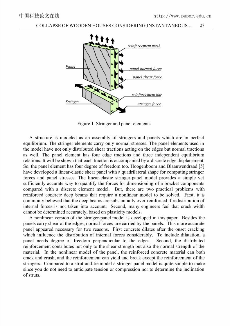
Figure 1. Stringer and panel elements
A structure is modeled as an assembly of stringers and panels which are in perfect
equilibrium. The stringer elements carry only normal stresses. The panel elements used in
the model have not only distributed shear tractions acting on the edges but normal tractions
as well. The panel element has four edge tractions and three independent equilibrium
relations. It will be shown that each traction is accompanied by a discrete edge displacement.
So, the panel element has four degree of freedom too. Hoogenboom and Blaauwendraad [5]
have developed a linear-elastic shear panel with a quadrilateral shape for computing stringerforces and panel stresses. The linear-elastic stringer-panel model provides a simple yet
sufficiently accurate way to quantify the forces for dimensioning of a bracket components
compared with a discrete element model. But, there are two practical problems with
reinforced concrete deep beams that require a nonlinear model to be solved. First, it is
commonly believed that the deep beams are substantially over-reinforced if redistribution of
internal forces is not taken into account. Second, many engineers feel that crack width
cannot be determined accurately, based on plasticity models.
A nonlinear version of the stringer-panel model is developed in this paper. Besides the
panels carry shear at the edges, normal forces are carried by the panels. This more accurate
panel appeared necessary for two reasons. First concrete dilates after the onset crackingwhich influence the distribution of internal forces considerably. To include dilatation, a
panel needs degree of freedom perpendicular to the edges. Second, the distributed
reinforcement contributes not only to the shear strength but also the normal strength of the
material. In the nonlinear model of the panel, the reinforced concrete material can both
crack and crush, and the reinforcement can yield and break except the reinforcement of the
stringers. Compared to a strut-and-tie model a stringer-panel model is quite simple to make
since you do not need to anticipate tension or compression nor to determine the inclination
of struts.
中国科技论文在线 http://www.paper.edu.cn

7/23/2019 wangquanfeng-200712-2
http://slidepdf.com/reader/full/wangquanfeng-200712-2 4/16
Yasuko Kuwata and Shiro Takada 28
2.2 Stress-strain relationships
The modified compression field theory (MCFT) was proposed several years ago as a simple
analytical model for predicting the load-deformation response of reinforced concrete
elements subjected to in-plane shear and normal stresses [6]. The material model consideredequilibrium and compatibility conditions within an element in terms of average strains.
Local stress conditions at crack locations were also considered. In the MCFT the cracked
concrete is treated as a new material with unique stress-strain characteristics. New
constitutive relations have been proposed for cracked concrete, based on extensive test data,
reflecting significant influences due to compression softening and tension-stiffening
mechanisms. The formulations of the MCFT were subsequently incorporated into a
nonlinear finite element algorithm [7]. Accordingly, cracked reinforced concrete is treated
as an orthotropic material. The solution procedure used is based on a Stiffness formulation,
giving good numerical stability and providing much freedom in the definition of material
behavior models. The discrete element model consisting of stringers and panels herein ismade to reflect the nonlinear behavior of reinforced concrete deep beams by adopting the
formulations of the MCFT. Such analyses can be performed by simple modification of
existing linear elastic routines and modifications are based on a stiffness of the material.
2.3 Material modeling
The stresses in narrow webs of reinforced concrete deep beams can reasonably be
considered to be a plane stress. Modified compression field theory is used here. To model
nonlinear material response, the constitutive relations contained in the MCFT have been
adopted. The concrete compression strength fc used in the calculation can be obtained from
the measured cylinder compressive strength; the tensile strength of concrete is lowcompared with the compressive strength and the ductility of concrete under tension is very
limited, so the tension strength will be neglected; the reinforcements in both tension and
compression are assumed to be rigid-perfectly plastic with yield stress f y. Perfect bond is
assumed and dowel action is neglected. E c and E s are the modulus of elasticity of concrete
and reinforcement, respectively, and Ec is calculated according to ACI [8]
c c= 57,000 f E
(1)
in which f c is in psi.
2.4 Element tangent stiffness matrix
The numerical formulations developed in this paper relied on work previously formulations.
To obtain a more accurate estimate for the load-bearing capacity of the reinforced concrete
deep beam, the force-displacement relations of the two types of stringer element and panel
element, based on virtual work equation, complementary energy principle and the Hellinger
Reissner functional, are derived with shape functions for displacement or stress fields on
curvilinear co-ordinates or in curvilinear direction. As Figure 2 shows the panel dimensions
are
中国科技论文在线 http://www.paper.edu.cn

7/23/2019 wangquanfeng-200712-2
http://slidepdf.com/reader/full/wangquanfeng-200712-2 5/16
COLLAPSE OF WOODEN HOUSES CONSIDERING INSTANTANEOUS... 29
2
xx
2
xxa 4132
+−
+=
2
xx
2
xxc 2143
+−
+=
(2)
2
xx
2
xy b 2143 +−+= 2
yy
2
yyd 4132 +−+=
2
3
4
1
y
xb
a
c
d
1
Figure 2. Panel dimensions
For example the variable x1 is the x co-ordinate of vertex 1. Having determined an
appropriate constitutive matrix D, the stiffness k p for a panel element can be evaluated using
a direct method [9]. The computations involved can be summarized as
k p = Q P D H A (3)
The Q together with P embody the equilibrium of the panel, for a rectangular panel
2 2
4 4
4
4
2 2
4 4
2 2
4 4 4
4
4
2 2
4 4
. 2 . . . . . .
. . 2 . . . . .
1
2
. . . . . 2 . .
. . . . . . 2 .
a bc bd t ab a bc bd t ab
t
t
ab ac t ad b ab ac t ad b
t a bc bd t ab a bc bd t ab
t
t
ab ac t ad b ab ac t ad b
− − − − − −
− − − − − − = − − − − − − − − − − − −
Q (4)
Where t 4 = a2 + b2. For clarity the zero elements of the matrix are represented with dots.
The matrices A and H embody the kinematic relations of the panel, and they are
中国科技论文在线 http://www.paper.edu.cn

7/23/2019 wangquanfeng-200712-2
http://slidepdf.com/reader/full/wangquanfeng-200712-2 6/16
Yasuko Kuwata and Shiro Takada 30
1 1 1 1
1 1 1 1
1 1 1 1 1 1 1 1
2 2 2 2
3 3 3 3
. . . .
. . . .
2 2 2 2 2 2 2 2
. . . .
. . . .
d b d b
t t t t
a c a c
t t t t
a d c b a d c b
t t t t t t t t
a a a a
t t t t
b b b b
t t t t
− −
− − − − − −= − −
− −
A
(5)
1 . . .
. 1 . . 1
. . 2 . .
1 . . 1 .
. 1 . .
. . 2 . .
1 . . .
. 1 . . 1
. . 2 . .
1 . . 1 .
. 1 . .
. . 2 . .
c
a
d
b
c
a
d
b
−
−
=
−
−
H
(6)
in which
cdabt1
−= ( ) 2222
2d bca
2
1t −+−= ( ) 2222
3cad b
2
1t −+−= ; (7)
In general, the tangent stiffness matrix, kp of the panel is not symmetric for two reasons:
First, the matrix D is not symmetric due to the nonlinear material behavior. Second, the
equilibrium matrix QP does not equal the transpose of the kinematic matrix HA. In this
paper, the tangent matrix of the panel, k p is not derived analytically but computed by the
program. This is necessary because the constitute model contains iterations.
中国科技论文在线 http://www.paper.edu.cn
7/23/2019 wangquanfeng-200712-2
http://slidepdf.com/reader/full/wangquanfeng-200712-2 7/16
COLLAPSE OF WOODEN HOUSES CONSIDERING INSTANTANEOUS... 31
In the stringer-panel model, the concentrated reinforcement and the compressed concrete
in the stringers behave linearly, while changing stiffness due to cracking of the tensioned
concrete is included. The stiffness k s for a stringer element can be evaluated using
complementary potential method [9]. The computations involved can be summarized as
k s = TT BT F − 1 B T (8)
Due to the sparse matrices involved it is computationally efficient to derive the stiffness
matrix analytically instead of computing the matrix multiplications, in which defining matrix
B is
−
⋅
⋅
−=
11
11 B
(9)
F is the flexibility matrix, and it can be observed easily that the matrix is symmetric
regardless of the constitutive behavior. In case of a nonlinear model the rotation matrix T is
γβα
⋅⋅⋅
⋅⋅⋅
γβα
⋅⋅⋅
⋅⋅⋅
⋅⋅⋅
γβα
=
coscoscos
coscoscos
coscoscos
T (10)
The α is the angle of the x axis of the global reference system and the stringer axis. The
β and γ are between the stringer axis and the y and the z axis, respectively.
3. NUMERICAL IMPLEMENTATION
The purpose of the following section is therefore to outline the main features of this
analytical method. Further details may be found in Hoogenboom [9]. The numerical
implementation of the static approach first requires the discretization of the structure into a
few stringer elements and a few panel elements.
3.1 The Number and positions of the newton Côtes integrationDuring the simulation process of a stringer-panel model, the panel forces are computed for
every panel, in every load step and every equilibrium iteration. For computing the stresses
in an integration point, a few comments have to be made on the number and positions of the
integration. Because four integration points can be positioned such that any numbering
results in integration points at the same position, the panel is designed with four integration
points, which contain all together twelve strain components of panel. The integration points
could be located somewhere in the interior of the panels as is common in the discrete
element method. However, since the strain field of the panel is linear in x and y directions,
strains and stresses at the edges of the panel become larger than at the integration points. As
a consequence, at the edge the stresses can become larger than the ultimate material stress,
中国科技论文在线 http://www.paper.edu.cn

7/23/2019 wangquanfeng-200712-2
http://slidepdf.com/reader/full/wangquanfeng-200712-2 8/16
Yasuko Kuwata and Shiro Takada 32
which is an unsafe approximation with respect to the lower bound theorem of plasticity
theory. To be safe the integration points should be chosen at the panel vertices since there
the largest strain occurs. However, the strain field in the neighbourhood of the vertices is
less accurate especially in panels with a highly nonrectangular shape. So, as a compromise,the integration points are unconventionally positioned at the midst of the edges.
3.2 Nonlinear algorithm
Suppose there is a difference between the applied quantities (forces and displacements) and
the internal quantities. The difference between an internal nodal displacement and an
applied nodal displacement is called a gap. The difference between an internal force and an
applied nodal force is called an unbalance. Clearly, the gaps and unbalances should be zero.
If the model is loaded, the gaps and unbalances are present. These differences can be
reduced with a computational algorithm. Newton Raphson method is implemented in the
stringer-panel model. For this we consider the differences as small extra loads and extradisplacements onto the structure. When the structure is assumed to behave linearly the extra
internal displacements can be computed with the well known displacement method of linear-
elastic analysis: Just assemble the global stiffness matrix, process supports and solve the
unknown displacements with the load. The resulting small displacements are added to the
internal displacements we already had. Subsequently, the new unbalances will be smaller
than before. The gaps are not closed completely due to the computational inaccuracies and
the unbalances are not completely eliminated because the structure does not really behave
linearly. The remaining gaps and unbalances can be reduced in a next iteration. This is
repeated until they are sufficiently small. To compute the complete structural behavior the
load is increased in subsequent steps. In every step the above algorithm will adjust theinternal nodal displacements in a number of iterations in order to keep up with the load as
good as it can. The numerical techniques are shown in Figure 3 for the solution procedure
with the stringer-panel model.
Predictor P
m+1
P
L o a d
mm
K
m+1K
P
m+1m+1
m+11
Iterationu
mm0
Displacement
Figure 3. Numerical scheme for incremental analysis
中国科技论文在线 http://www.paper.edu.cn

7/23/2019 wangquanfeng-200712-2
http://slidepdf.com/reader/full/wangquanfeng-200712-2 9/16
COLLAPSE OF WOODEN HOUSES CONSIDERING INSTANTANEOUS... 33
here,1m
1u+
is the initial displacement for the (m+1)th minimum load1mP
+; um is the
converged solution at the mth minimum loadmP ;
1m0u
+is the reference positions at the
respective load levels, and
m0
K and
1m0
K
+
are all the initial stiffness. Therefore, during thewhole process of iterative computation the analysis is carried out incrementally.
Apparently, this numerical technique for the incremental analysis is effective because in the
iterative solution of a numerical problem, the stability of the numerical solution can
eventually be achieved through iterations as long as a predictor is reasonable.
3.3 Load control
It is impossible to identify the collapse mode of a given panel with a conventional Newton
Raphson iterative analysis under load control since failure of the numerical procedure to
converge would be mistakenly interpreted as material failure of the panel. A Newton
Raphson iterative analysis under displacement control is not possible yet, because of theinability to control the displacements of several panel points while maintaining a
proportional uniform shear and normal biaxial stress [10]. If a conventional load-controlled
analysis technique is adopted, it is very difficult to clearly define the ultimate load too. This
difficulty can be overcome by adopting a form of arc-length control, whereby, the load
factor is allowed to vary during the iterations, and a constraint is applied to limit the
incremental displacement [11, 12]. This is sufficient for most situations and it is
implemented for the nonlinear analysis of the stringer-panel model.
3.4 Convergence criterion
A criterion is necessary to end the equilibrium iterations. Two criteria are implemented inthe stringer-panel model which both have to be fulfilled:
The largest unbalance force must be 30 times smaller than the largest of the stringer and
panel nodal forces.
The latest displacement gap of the applied displacements must be 30 times smaller than
the largest internal nodal displacement.
3.5 Smooth relations
The stiffness coefficients initially undergo remarked variation as the behavior changes from
uncracked isotropic to cracked orthotropic response or when material starts yielding. When
a tangent stiffness matrix is used in the computation of the model behavior, this will oftenlead to divergence of the iterative process. In this paper, instead of iterating with the local
tangent stiffness matrix the initial linear-elastic tangent stiffness matrix is used which can be
obtained when the model is not loaded. With this method the computation is very robust,
but, the convergence goes slowly and many iterations are required to arrive at an equilibrium
state.
4. EXPERIMENTAL RESULTS
The stringer-panel model is validated by comparison with test results from eight reinforced
中国科技论文在线 http://www.paper.edu.cn

7/23/2019 wangquanfeng-200712-2
http://slidepdf.com/reader/full/wangquanfeng-200712-2 10/16
Yasuko Kuwata and Shiro Takada 34
concrete continuous deep beams tested by [13] at Cambridge University in the United
Kingdom as shown in Figure 4. These deep beams were to be an extensive research
program with the objective to modify the current codes of practice for shear in reinforced
concrete continuous deep beams because these codes [8, 14] were based on tests of simplysupported deep beams only. The deep beams in the following correlation studies are
referred to CDB1, CDB2, CDB3, CDB4, CDB5, CDB6, CDB7 and CDB8 in the original
test series. After a shortly description of the observed deep beam behavior, the numerical
results with the proposed model are compared with the measured results by Ashour [13].
660 680 660680 160160
3000 mm 120
625
4Ø12 + 2Ø10
4Ø12
stirrups Ø8-1002Ø8-125
Figure 4. Two-span reinforced concrete deep beam
The overall dimensions of each deep beam are shown in Figure 4. All tested beams havethe same length and width: the length is 3,000mm and the width is 120mm. The location of
center lines of loads and supports are the same for all test beams. Only the beam depth is
varied to obtain two different shear-span-to-depth ratios: for Series I, the depth is 625mm,
and for Series II the depth is 425mm (Figure 5). The details of reinforcement for each deep
beam are shown in Table 1. The amount of vertical web reinforcement included three
levels: none, a low amount, and a large amount. The amount of horizontal web
reinforcement studied is none, a low amount, and a large amount. The vertical web
reinforcement is closed stirrups and the horizontal web reinforcement is longitudinal bars in
both sides of the beam. The main longitudinal top and bottom reinforcements are kept
constant for each series except for the last beam (CDB5 and CDB8) in each series, where theamount of top and bottom reinforcements are reduced. All longitudinal bottom
reinforcements extended the full length of the beam and through the depth to provide
sufficient anchorage.
The material properties of concrete and reinforcement in the deep beam are given in
Table 2. All longitudinal top and bottom reinforcements are high-yield ribbed steel bars and
the web reinforcement is normal mild steel. The deep beam and the load are symmetrical, so
only half the beam is modeled with a stringer-panel model as shown in Figure 5. The
stringer-panel model of half the continuous deep beam consists of 7 stringer elements and 2
panel elements.
中国科技论文在线 http://www.paper.edu.cn

7/23/2019 wangquanfeng-200712-2
http://slidepdf.com/reader/full/wangquanfeng-200712-2 11/16
COLLAPSE OF WOODEN HOUSES CONSIDERING INSTANTANEOUS... 35
Table 1: Details of specimen reinforcement
Longitudinal Reinforcement Web reinforcementBeam No.
Bottom Top Horizontal Vertical
CDB1 4Φ12mm 4 Φ 12+2 Φ 10mm 8 Φ 8mm 29Φ8mm
CDB2 4 Φ 12mm 4 Φ 12+2 Φ 10mm 4 Φ 8mm 15 Φ 8mm
CDB3 4 Φ 12mm 4 Φ 12+2 Φ 10mm 4 Φ 8mm ---
CDB4 4 Φ 12mm 4 Φ 12+2 Φ10mm --- 15 Φ 8mm
CDB5 2 Φ 12mm 2 Φ 12mm 4 Φ 8mm 15 Φ 8mm
CDB6 2 Φ 12+2 Φ 10mm 2 Φ 12+2 Φ 10mm 4 Φ 6mm 29 Φ 6mm
CDB7 2 Φ12+2 Φ 10mm 2 Φ 12+2 Φ 10mm 2 Φ 6mm 15 Φ 6mm
CDB8 2 Φ 12mm 2 Φ 12mm 2 Φ 6mm 15 Φ 6mm
Table 2: Properties of concrete and reinforcement for numerical tests (Mpa)
No. fc ft Ec fsy fwy Es Ew
CDB1 30.00 4.24 25921. 500 365 2.05E05 2.13E05
CDB2 33.1 4.80 27227. 500 365 2.05E05 2.13E05
CDB3 22.0 3.99 22198. 500 365 2.05E05 2.13E05
CDB4 28.0 4.32 25042. 500 365 2.05E05 2.13E05
CDB5 28.7 4.20 25353. 500 365 2.05E05 2.13E05
CDB6 22.5 4.19 22448. 500 330 2.05E05 2.04E05
CDB7 26.7 4.85 24454. 500 330 2.05E05 2.04E05
CDB8 23.6 4.11 22991. 500 330 2.05E05 2.04E05
中国科技论文在线 http://www.paper.edu.cn

7/23/2019 wangquanfeng-200712-2
http://slidepdf.com/reader/full/wangquanfeng-200712-2 12/16
Yasuko Kuwata and Shiro Takada 36
660 640
625 540
45
40
Series I (CDB1-5)
P
660 640
425 360
45
40
Series II (CDB6-8)
P
Figure 5. Stringer-panel models of the deep beams
Nonlinear analyses of reinforced concrete deep beams can be achieved by incorporating the
element formulations described above into an iterative linear-elastic analysis procedure.
Through each iteration, the material stiffness and element stiffness matrices are progressively
refined until numerical stability. By adopting this stringer-panel model, the ultimate loads, P c,
obtained from the numerical analyses are compared with the experimental values, P t , [13] in
Table 3, in which the abrupt loss of strength after ultimate load attainment indicates concrete
crushing. Consequently, the final collapse load is well defined.
Table 3: Calculated failure loads and comparison with experimental results (kN)
No. Pc Pt Pc/ Pt
CDB1 530.0 539.6 0.98
CDB2 407.0 466.0 0.87
CDB3 228.0 279.6 0.82
CDB4 352.0 434.1 0.81
CDB5 291.0 402.2 0.72
CDB6 253.0 242.8 1.04
CDB7 218.0 218.3 1.00
CDB8 160.0 188.8 0.85
中国科技论文在线 http://www.paper.edu.cn

7/23/2019 wangquanfeng-200712-2
http://slidepdf.com/reader/full/wangquanfeng-200712-2 13/16
COLLAPSE OF WOODEN HOUSES CONSIDERING INSTANTANEOUS... 37
It can be seen that the numerical results should be accepted from the comparison.
Nevertheless, these comparisons of the stringer-panel model with experiments are not
enough to establish its validity in all situations. Much more test data is available which
should be used to validate or falsify the method and obtain more information on itsaccuracy.
Also the nonlinear analysis also provides useful information regarding the stringer forces.
5. ANALYSES OF NUMERICAL RESULTS
The capabilities and limitations of the procedure presented are reflected in the sample
analyses discussed below.
5.1 CDB1The best agreement with the experimental result is obtained with the stringer-panel model.
The beam fails at 530.0kN which is very close to the experimental result, 539.6 kN [13].
5.2 CDB2
The model collapses at 87% of the experimental ultimate load. CDB2 and CDB1 have equal
amounts of longitudinal reinforcement but the amount of web reinforcement is smaller than
the one of CDB1. Therefore, CDB2 gets a smaller ultimate load than CDB1.
5.3 CDB3 and CDB4
Compared with CDB1 and CDB2, CDB3 has light horizontal web reinforcement and novertical web reinforcement, CDB4 is just opposite. The web horizontal reinforcement in
CDB3 yields at failure [13]. Because of the large different in the reinforcements in the
horizontal and vertical directions of the panel, contrasted with the experimental results, CDB
3 and 4 both significant underestimated the collapse that is about 18% and 19% too low,
respectively.
5.4 CDB5 and CDB8
Except the clear shear span-to-depth ratio is different for CDB5 and CDB8, the amount of
main longitudinal top and bottom reinforcements are reduced, compared with other test deep
beams. This involves the yielding of the reinforcement after shear/compression failure inthe concrete. Ashour’s experiment [13] shows that the top and bottom longitudinal
reinforcements yield besides most of the web reinforcement yields. But, indeed, in the
stringer-panel model, the concentrated reinforcement and the compressed concrete in the
stringers behave linearly, while changing stiffness due to cracking of the tensioned concrete
is included. Such a significant swings occur. The numerical failure loads of CDB5 and
CDB8 is 72% and 85% of that obtained by the experiment, respectively.
5.5 CDB6 and CDB7
The computed results of CDB6 and CDB7 involved only change of web reinforcement, and
just before failure major redistribution of the vertical stirrup strain takes place and this
中国科技论文在线 http://www.paper.edu.cn
7/23/2019 wangquanfeng-200712-2
http://slidepdf.com/reader/full/wangquanfeng-200712-2 14/16
Yasuko Kuwata and Shiro Takada 38
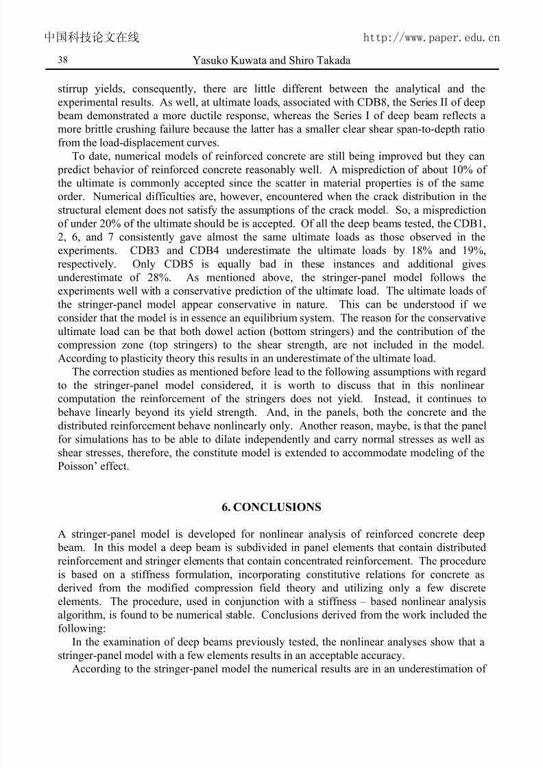
stirrup yields, consequently, there are little different between the analytical and the
experimental results. As well, at ultimate loads, associated with CDB8, the Series II of deep
beam demonstrated a more ductile response, whereas the Series I of deep beam reflects a
more brittle crushing failure because the latter has a smaller clear shear span-to-depth ratiofrom the load-displacement curves.
To date, numerical models of reinforced concrete are still being improved but they can
predict behavior of reinforced concrete reasonably well. A misprediction of about 10% of
the ultimate is commonly accepted since the scatter in material properties is of the same
order. Numerical difficulties are, however, encountered when the crack distribution in the
structural element does not satisfy the assumptions of the crack model. So, a misprediction
of under 20% of the ultimate should be is accepted. Of all the deep beams tested, the CDB1,
2, 6, and 7 consistently gave almost the same ultimate loads as those observed in the
experiments. CDB3 and CDB4 underestimate the ultimate loads by 18% and 19%,
respectively. Only CDB5 is equally bad in these instances and additional givesunderestimate of 28%. As mentioned above, the stringer-panel model follows the
experiments well with a conservative prediction of the ultimate load. The ultimate loads of
the stringer-panel model appear conservative in nature. This can be understood if we
consider that the model is in essence an equilibrium system. The reason for the conservative
ultimate load can be that both dowel action (bottom stringers) and the contribution of the
compression zone (top stringers) to the shear strength, are not included in the model.
According to plasticity theory this results in an underestimate of the ultimate load.
The correction studies as mentioned before lead to the following assumptions with regard
to the stringer-panel model considered, it is worth to discuss that in this nonlinear
computation the reinforcement of the stringers does not yield. Instead, it continues to behave linearly beyond its yield strength. And, in the panels, both the concrete and the
distributed reinforcement behave nonlinearly only. Another reason, maybe, is that the panel
for simulations has to be able to dilate independently and carry normal stresses as well as
shear stresses, therefore, the constitute model is extended to accommodate modeling of the
Poisson’ effect.
6. CONCLUSIONS
A stringer-panel model is developed for nonlinear analysis of reinforced concrete deep beam. In this model a deep beam is subdivided in panel elements that contain distributed
reinforcement and stringer elements that contain concentrated reinforcement. The procedure
is based on a stiffness formulation, incorporating constitutive relations for concrete as
derived from the modified compression field theory and utilizing only a few discrete
elements. The procedure, used in conjunction with a stiffness – based nonlinear analysis
algorithm, is found to be numerical stable. Conclusions derived from the work included the
following:
In the examination of deep beams previously tested, the nonlinear analyses show that a
stringer-panel model with a few elements results in an acceptable accuracy.
According to the stringer-panel model the numerical results are in an underestimation of
中国科技论文在线 http://www.paper.edu.cn

7/23/2019 wangquanfeng-200712-2
http://slidepdf.com/reader/full/wangquanfeng-200712-2 15/16
COLLAPSE OF WOODEN HOUSES CONSIDERING INSTANTANEOUS... 39
the ultimate load. The ultimate load of the stringer-panel model appears conservative in
nature because a tested structure somehow finds extra ways to carry forces that are not
included in the model.
Because the present stringer-panel model involves only a few numbered elements, therehas been no need to tackle “mesh dependency” problem. Consequently, many of the
difficulties that, in the presence of softening material, are associated with alternative
equilibrium paths have been avoided.
Compared to a strut-and-tie model a stringer-panel model is quite simple to be made
since one does not need to anticipate tension or compression nor to determine the inclination
of struts.
Newton Raphson is selected in the stringer-panel model, When a tangent stiffness matrix
is used in the nonlinear computation, this will often leads to divergence of the iterative
process. In the stringer-panel model, instead of iterating with the local tangent stiffness
matrix the initial linear-elastic tangent stiffness is used for all iterations. This works almostalways and is often fast enough.
If the stringer-panel model is to obtain data on the failure load, a technique such as the
arc length method must be used so that numerical failure does not precede structural failure.
The performance of the arc length method is superior to iterations under load control in the
case of reinforced concrete panels. Not only does the arc length method converge faster, but
it also yields more accurate estimates of failure load.
REFERENCES
1. Averbuch, D., and de Buhan, P. Shear design of reinforced concrete deep beams: A
numerical approach. ASCE J. Struct. Engrg ., No. 3, 125(1999)309-318.
2. Ritter, W. Die Bauweise Hennebique. Schweizersche Bauzeitung. (Zurich) No. 7,
33(1899)59-61 (in German).
3. Siao, S.W. Deep beams revisited. ACI Structural Journal , No. 1, 92(1995) 95-102.
4. Blaauwendraad, J., and Hoogenboom, P.C.J. Stringer panel model for structural
concrete design. ACI Structural Journal , No. 3, 93(1996) 295-305.
5. Hoogenboom, P.C.J., and Blaauwendraad, J. Quadrilateral shear panel. J. of
Engineering Structures, No. 10, 22(2000)1690-1698.
6. Vecchio, F.J., and Collins, M.P. The modified compression field theory for reinforcedconcrete elements subjected to shear. ACI Struct. J., No.2, 83(1986) 219-231.
7. Vecchio, F.J. Nonlinear finite element analysis of reinforced concrete membranes.
ACI Struct. J ., No.1, 86(1989) 26-35.
8. American Concrete Institute (ACI). Building code requirements for structural concrete
and commentary. ACI 318-89, Detroit, USA, 1989.
9. Hoogenboom, P.C.J. Discrete Elements and Nonlinearity in Design of Structural
Concrete Walls. Doctor Thesis, Deflt University of Technology, July 1998.
10. Ayoub, A., and Filippou, F.C. Nonlinear finite-element analysis of RC shear panels
and walls. ASCE J. Struct. Engrg ., No.3, 124(1998) 298-308.
11. Ramm, E. Nonlinear Finite Element Analysis in Structural Mechanics: Strategies for
中国科技论文在线 http://www.paper.edu.cn

7/23/2019 wangquanfeng-200712-2
http://slidepdf.com/reader/full/wangquanfeng-200712-2 16/16
Yasuko Kuwata and Shiro Takada 40
tracing the nonlinear response near limit points. Springer-Verlag, Berlin, 1981, pp. 63-
89.
12. Crisfield, M.A. Accelerated solution techniques and concrete cracking. J. Comput.
Meths Appl. Mech. and Engrg ., 33(1982) 585-607.13. Ashour, A.F. Tests of reinforced concrete continuous deep beams. ACI Struct. J .,
No.1, 94(1997) 3-12.
14. CIRIA Guide. The Design of Deep Beams in Reinforced Concrete. Over Arup and
Partners and Construction Industry and Information Association. London, 1977
(Reprint in 1984).
中国科技论文在线 http://www.paper.edu.cn


![[서울대 권장도서 100권]광장-최인훈 - Egloospds7.egloos.com/pds/200712/06/53/SNU_books.doc · Web view그에 의하면 ‘역사’ 9권은 각기 3개(제5권은](https://static.fdocument.pub/doc/165x107/5fb7ba9a063efc31e65b0dee/oeeoe-eoeeoe-100eoee-oe-web-view-e-e-aa.jpg)