Ttcn3 Uc 2007 Concurrent Ttcn
21
1 © Telelogic AB Managing Concurrency and Parallel Testing with TTCN-3 Pierre Bentkowski, Principal Consultant TTCN-3 Users conference Asia 2007 Beijing, China Telelogic Tester™ 2 © Telelogic AB Concurrent TTCN-3 • Why do we need a concurrent test architecture? • What kind of architectures can be used? • How TTCN-3 supports such architectures? • A TTCN-3 example • TTCN-3 Configuration Operations • Tips and Guidelines
-
Upload
prem-panigrahi -
Category
Documents
-
view
19 -
download
0
Transcript of Ttcn3 Uc 2007 Concurrent Ttcn

1 © Telelogic AB
Managing Concurrency and Parallel Testing with TTCN-3
Pierre Bentkowski, Principal Consultant
TTCN-3 Users conference Asia 2007 Beijing, China
Telelogic Tester™
2 © Telelogic AB
Concurrent TTCN-3
• Why do we need a concurrent test architecture?
• What kind of architectures can be used?
• How TTCN-3 supports such architectures?
• A TTCN-3 example
• TTCN-3 Configuration Operations
• Tips and Guidelines
3 © Telelogic AB
SystemUnderTest
Tester1
Tester2
• PCO Point of Control and Observation (Port type)
• CP Control Point (Port type)
• MTC Main Test Component (Component type)
• PTC Parallel Test Component (Component type)
• TS Test System
• TSI Test System Interface
• SUT System Under Test
Terminology
4 © Telelogic AB
SUT
TS
MTC
PTC
PTC
PCO
PCO
CP
CP
TSI
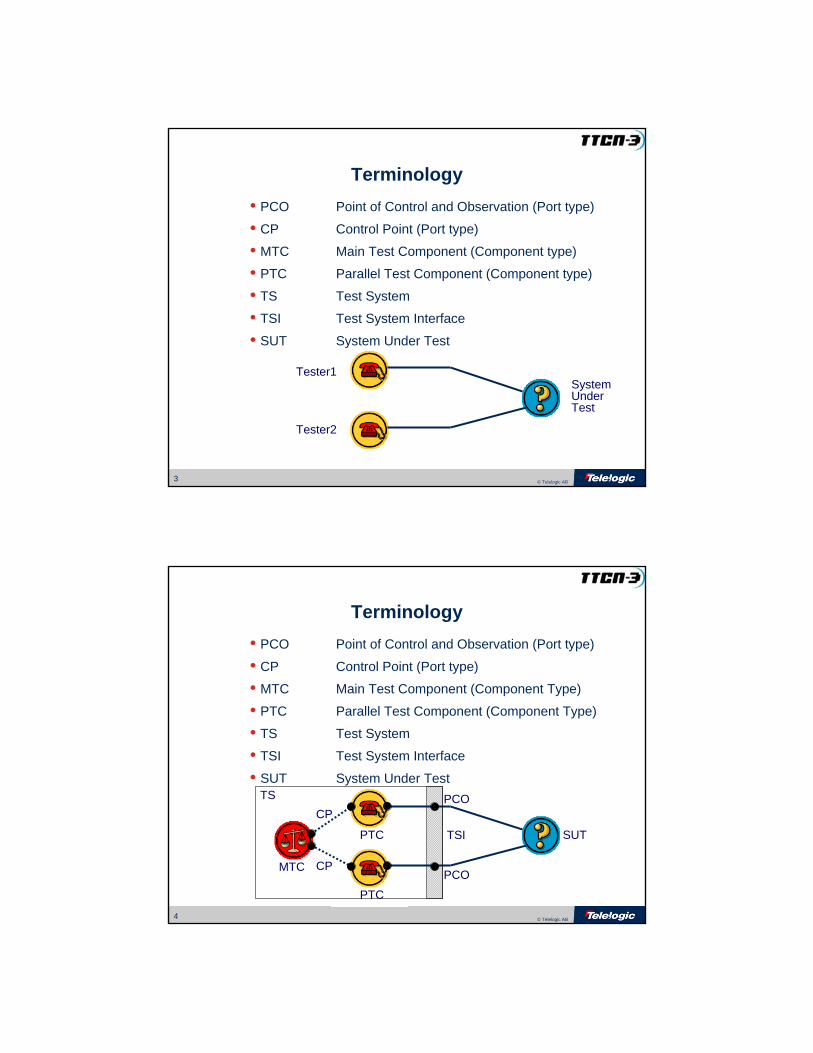
• PCO Point of Control and Observation (Port type)
• CP Control Point (Port type)
• MTC Main Test Component (Component Type)
• PTC Parallel Test Component (Component Type)
• TS Test System
• TSI Test System Interface
• SUT System Under Test
Terminology
5 © Telelogic AB
Why do we need a concurrent test architecture?
• By nature, devices and users which are interfaced to the SUT are functioning in a concurrent manner.
• Even with perfectly synchronized inputs to the SUT, there are no guaranties that the SUT will reply with the exact same sequence of outputs.
Tester1 Tester2SUT
6 © Telelogic AB
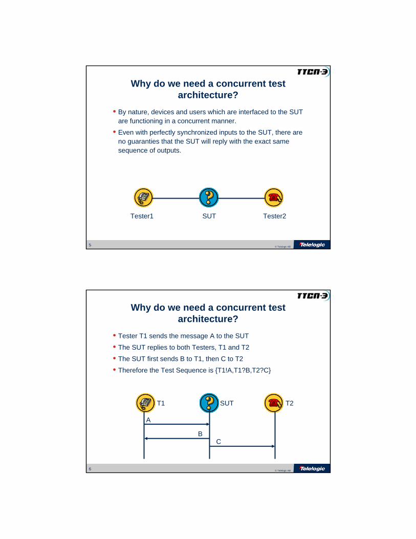
Why do we need a concurrent test architecture?
• Tester T1 sends the message A to the SUT
• The SUT replies to both Testers, T1 and T2
• The SUT first sends B to T1, then C to T2
• Therefore the Test Sequence is {T1!A,T1?B,T2?C}
A
BC
T1 T2SUT

7 © Telelogic AB
Why do we need a concurrent test architecture?
• Tester T1 sends the message A to the SUT
• The SUT replies to both Testers, T1 and T2
• The SUT first sends C to T2, then B to T1
• Therefore the Test Sequence is {T1!A,T2?C,T1?B}
A
BC
T1 T2SUT
8 © Telelogic AB
A
BC
T1 T2SUT
Why do we need a concurrent test architecture?
• Tester T1 sends the message A to the SUT
• The SUT replies to both Testers, T1 and T2
• The SUT first sends B to T1, then C to T2
• The communication channel adds a delay on B
• Therefore the Test Sequence is {T1!A,T2?C,T1?B}
9 © Telelogic AB
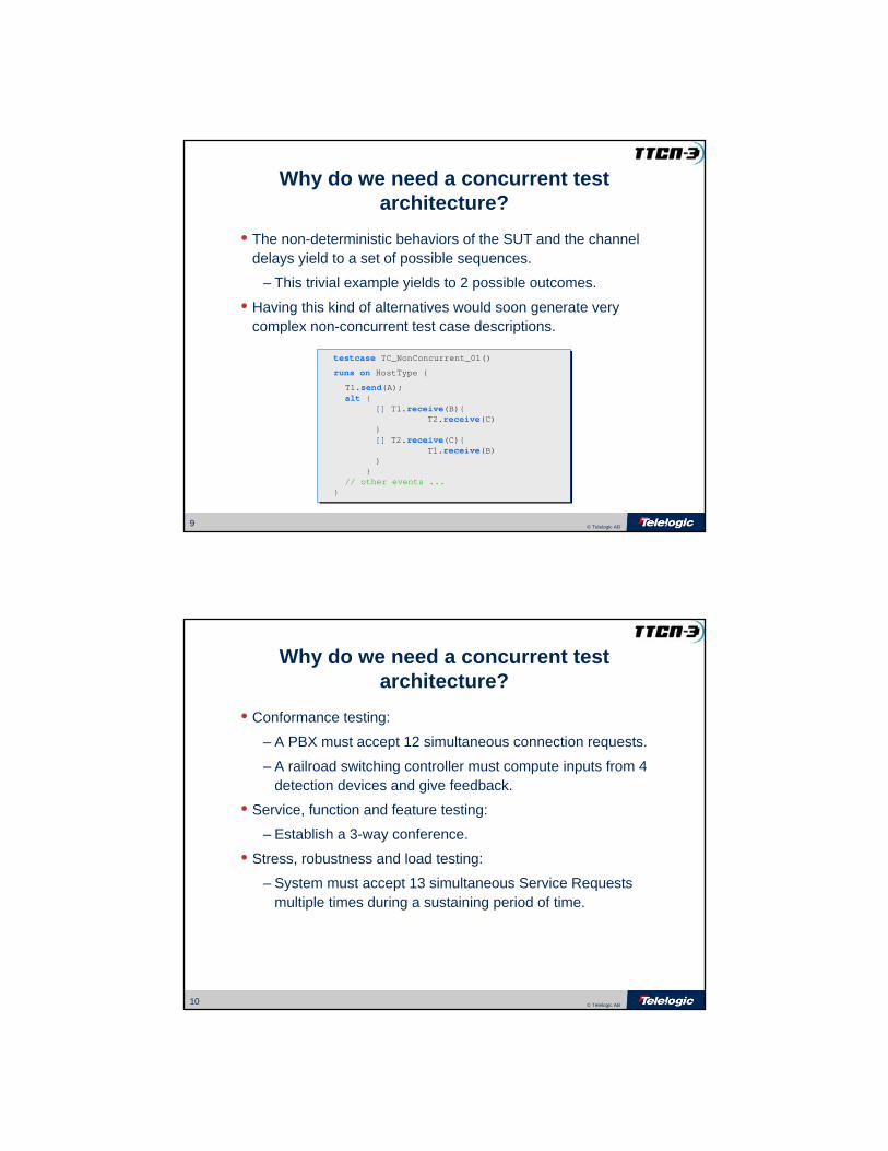
Why do we need a concurrent test architecture?
• The non-deterministic behaviors of the SUT and the channel delays yield to a set of possible sequences.
– This trivial example yields to 2 possible outcomes.
• Having this kind of alternatives would soon generate very complex non-concurrent test case descriptions.
testcase TC_NonConcurrent_01()
runs on HostType {
T1.send(A);alt {
[] T1.receive(B){T2.receive(C)
}[] T2.receive(C){
T1.receive(B)}
}// other events ...
}
testcase TC_NonConcurrent_01()
runs on HostType {
T1.send(A);alt {
[] T1.receive(B){T2.receive(C)
}[] T2.receive(C){
T1.receive(B)}
}// other events ...
}
10 © Telelogic AB
Why do we need a concurrent test architecture?
• Conformance testing:
– A PBX must accept 12 simultaneous connection requests.
– A railroad switching controller must compute inputs from 4 detection devices and give feedback.
• Service, function and feature testing:
– Establish a 3-way conference.
• Stress, robustness and load testing:
– System must accept 13 simultaneous Service Requests multiple times during a sustaining period of time.
11 © Telelogic AB
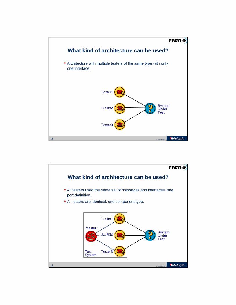
What kind of architecture can be used?
• Architecture with multiple testers of the same type with only one interface.
SystemUnderTest
Tester1
Tester2
Tester3
12 © Telelogic AB
What kind of architecture can be used?
• All testers used the same set of messages and interfaces: one port definition.
• All testers are identical: one component type.
SystemUnderTest
Tester1
Tester3TestSystem
Master
Tester2
13 © Telelogic AB
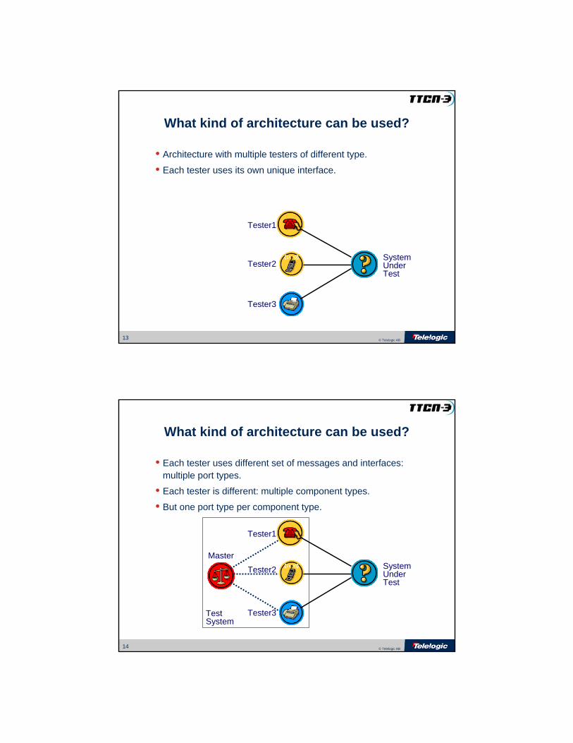
What kind of architecture can be used?
SystemUnderTest
Tester1
Tester2
Tester3
• Architecture with multiple testers of different type.
• Each tester uses its own unique interface.
14 © Telelogic AB
SystemUnderTest
Tester1
Tester2
Tester3TestSystem
Master
What kind of architecture can be used?
• Each tester uses different set of messages and interfaces: multiple port types.
• Each tester is different: multiple component types.
• But one port type per component type.
15 © Telelogic AB
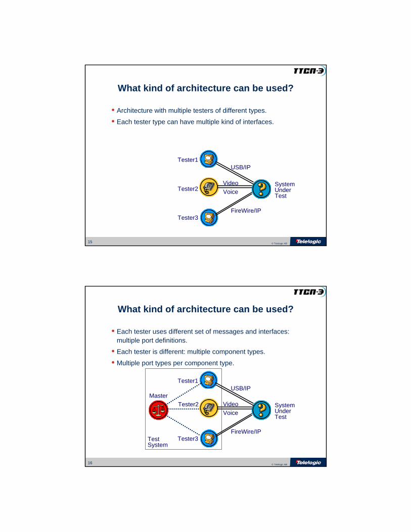
What kind of architecture can be used?
• Architecture with multiple testers of different types.
• Each tester type can have multiple kind of interfaces.
SystemUnderTest
Tester1
Tester2
Tester3FireWire/IP
VideoVoice
USB/IP
16 © Telelogic AB
SystemUnderTest
Tester1
Tester2
Tester3
VideoVoice
USB/IPMaster
TestSystem
What kind of architecture can be used?
• Each tester uses different set of messages and interfaces: multiple port definitions.
• Each tester is different: multiple component types.
• Multiple port types per component type.
FireWire/IP

17 © Telelogic AB
What kind of architecture can be used?• The Executable Test Suite can be:
– One Node - Multi-threaded (Simplest, Default)
– Multi-Node
– Mixed
TestSystem
Tester1Master
SUT
Tester2
Tester3
18 © Telelogic AB
• Dynamic creation of the test configuration– Creation of components
• create– Creation of connections between Components
• map, unmap– Creation of connections with the TSI/SUT
• connect, disconnect• Dynamic control of the component behavior
– Control of component behavior• start, stop, kill
– Lookup of component behavior• running, done, alive, killed
How TTCN-3 support such architectures?
19 © Telelogic AB
• Communication between components
– Exchange of messages between components
• send, receive
– Implicit verdict mechanism
• setverdict, getverdict
• none, pass, inconc, fail, error
How TTCN-3 support such architectures?
20 © Telelogic AB
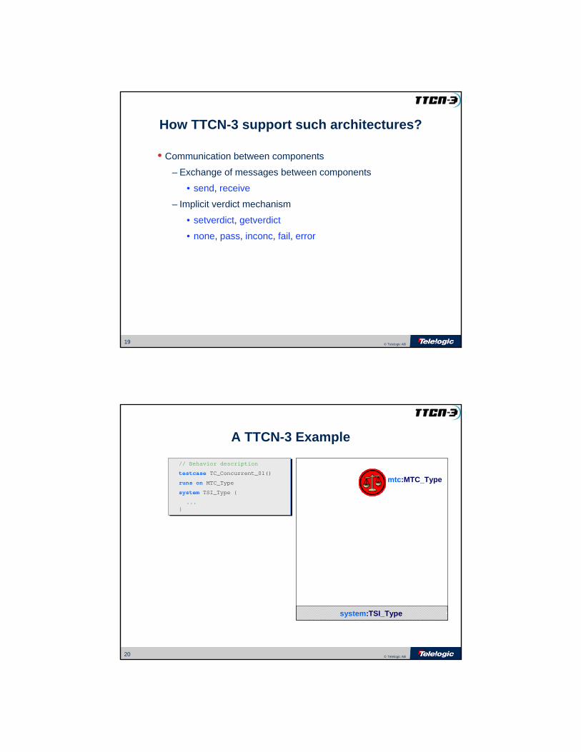
A TTCN-3 Example
mtc:MTC_Type
system:TSI_Type
// Behavior description
testcase TC_Concurrent_01()
runs on MTC_Type
system TSI_Type {
...}
// Behavior description
testcase TC_Concurrent_01()
runs on MTC_Type
system TSI_Type {
...}
21 © Telelogic AB
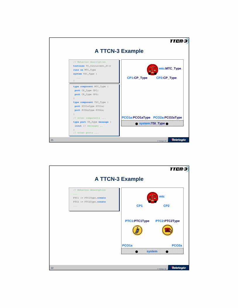
system:TSI_Type
mtc:MTC_Type
CP1:CP_Type CP2:CP_Type
A TTCN-3 Example
// Behavior description
testcase TC_Concurrent_01()
runs on MTC_Type
system TSI_Type {
...}
// Behavior description
testcase TC_Concurrent_01()
runs on MTC_Type
system TSI_Type {
...}
type component MTC_Type {
port CP_Type CP1;
port CP_Type CP2;
}
type component TSI_Type {
port PCO1aType PCO1a;
port PCO2aType PCO2a;
}
// other components ...
type port CP_Type message {
inout // messages ..
}// other ports ...
type component MTC_Type {
port CP_Type CP1;
port CP_Type CP2;
}
type component TSI_Type {
port PCO1aType PCO1a;
port PCO2aType PCO2a;
}
// other components ...
type port CP_Type message {
inout // messages ..
}// other ports ...
PCO1a:PCO1aType PCO2a:PCO2aType
22 © Telelogic AB
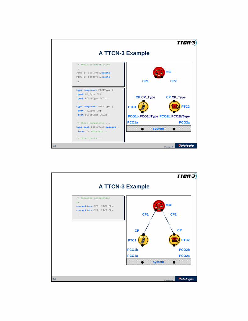
A TTCN-3 Example
// Behavior description
...
PTC1 := PTC1Type.create
PTC2 := PTC2Type.create
...
// Behavior description
...
PTC1 := PTC1Type.create
PTC2 := PTC2Type.create
...
system
PCO1a PCO2a
PTC1:PTC1Type PTC2:PTC2Type
mtc
CP1 CP2
23 © Telelogic AB
mtc
CP1 CP2
PTC2PTC1
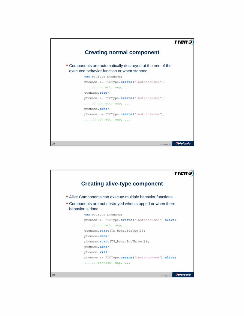
A TTCN-3 Example
// Behavior description
...
PTC1 := PTC1Type.create
PTC2 := PTC2Type.create
...
// Behavior description
...
PTC1 := PTC1Type.create
PTC2 := PTC2Type.create
...
type component PTC1Type {
port CP_Type CP;
port PCO1bType PCO1b;
}
type component PTC2Type {
port CP_Type CP;
port PCO2bType PCO2b;
}
// other components ...
type port PCO1bType message {
inout // messages ..
}// other ports ...
type component PTC1Type {
port CP_Type CP;
port PCO1bType PCO1b;
}
type component PTC2Type {
port CP_Type CP;
port PCO2bType PCO2b;
}
// other components ...
type port PCO1bType message {
inout // messages ..
}// other ports ...
system
PCO1a PCO2a
PCO1b:PCO1bType
CP:CP_Type
PCO2b:PCO2bType
CP:CP_Type
24 © Telelogic AB
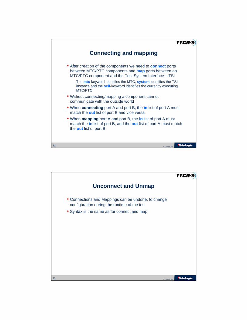
A TTCN-3 Example
// Behavior description
...
connect(mtc:CP1, PTC1:CP);
connect(mtc:CP2, PTC2:CP);
...
// Behavior description
...
connect(mtc:CP1, PTC1:CP);
connect(mtc:CP2, PTC2:CP);
...
mtc
CP1 CP2
system
PCO1a PCO2a
PTC1 PTC2
PCO1b PCO2b
CP CP

25 © Telelogic AB
A TTCN-3 Example
// Behavior description
...
map(PTC1:PCO1b, system:PCO1a);
map(PTC2:PCO2b, system:PCO2a);
...
// Behavior description
...
map(PTC1:PCO1b, system:PCO1a);
map(PTC2:PCO2b, system:PCO2a);
...
PCO1a
mtc
system
CP1 CP2
PTC1 PTC2
PCO2a
PCO2b
CP CP
PCO1b
26 © Telelogic AB
A TTCN-3 Example
// Behavior description
...
PTC1.start(TS_InitiateCall());
PTC2.start(TS_AnswerCall());
...
// Behavior description
...
PTC1.start(TS_InitiateCall());
PTC2.start(TS_AnswerCall());
...
function TS_InitiateCall()
runs on PTC1Type {
...
PCO1b.send(msg1);...
}
function TS_InitiateCall()
runs on PTC1Type {
...
PCO1b.send(msg1);...
}
function TS_AnswerCall()
runs on PTC2Type {
...
PCO2b.receive(msg2);
CP.send(statusConnected);...
}
function TS_AnswerCall()
runs on PTC2Type {
...
PCO2b.receive(msg2);
CP.send(statusConnected);...
}
system
PTC1 PTC2
mtc
msg1

27 © Telelogic AB
A TTCN-3 Example
// Behavior description
...
PTC1.start(TS_InitiateCall());
PTC2.start(TS_AnswerCall());
...
// Behavior description
...
PTC1.start(TS_InitiateCall());
PTC2.start(TS_AnswerCall());
...
function TS_InitiateCall()
runs on PTC1Type {
...
PCO1b.send(msg1);...
}
function TS_InitiateCall()
runs on PTC1Type {
...
PCO1b.send(msg1);...
}
function TS_AnswerCall()
runs on PTC2Type {
...
PCO2b.receive(msg2);
CP.send(statusConnected);...
}
function TS_AnswerCall()
runs on PTC2Type {
...
PCO2b.receive(msg2);
CP.send(statusConnected);...
}
system
PTC1 PTC2
mtc
msg2
28 © Telelogic AB
A TTCN-3 Example
// Behavior description
...
PTC1.start(TS_InitiateCall());
PTC2.start(TS_AnswerCall());
...
// Behavior description
...
PTC1.start(TS_InitiateCall());
PTC2.start(TS_AnswerCall());
...
function TS_InitiateCall()
runs on PTC1Type {
...
PCO1b.send(msg1);...
}
function TS_InitiateCall()
runs on PTC1Type {
...
PCO1b.send(msg1);...
}
function TS_AnswerCall()
runs on PTC2Type {
...
PCO2b.receive(msg2);
CP.send(statusConnected);...
}
function TS_AnswerCall()
runs on PTC2Type {
...
PCO2b.receive(msg2);
CP.send(statusConnected);...
}
statusConnected
system
PTC1 PTC2
mtc
29 © Telelogic AB
Creating normal component
• Components are automatically destroyed at the end of the executed behavior function or when stopped
var PTCType ptcname;
ptcname := PTCType.create("InstanceName");
... // connect, map, ...
ptcname.stop;
ptcname := PTCType.create("InstanceName");
... // connect, map, ...
ptcname.done;
ptcname := PTCType.create("InstanceName");
... // connect, map, ...
30 © Telelogic AB
Creating alive-type component
• Alive Components can execute multiple behavior functions
• Components are not destroyed when stopped or when there behavior is done
var PTCType ptcname;
ptcname := PTCType.create("InstanceName") alive;
... // connect, map, ...
ptcname.start(TS_BehaviorTwo());
ptcname.done;
ptcname.start(TS_BehaviorThree());
ptcname.done;
ptcname.kill;
ptcname := PTCType.create("InstanceName") alive;
... // connect, map, ...
31 © Telelogic AB
Connecting and mapping
• After creation of the components we need to connect ports between MTC/PTC components and map ports between an MTC/PTC component and the Test System Interface – TSI
– The mtc-keyword identifies the MTC, system identifies the TSI instance and the self-keyword identifies the currently executing MTC/PTC
• Without connecting/mapping a component cannot communicate with the outside world
• When connecting port A and port B, the in list of port A must match the out list of port B and vice versa
• When mapping port A and port B, the in list of port A must match the in list of port B, and the out list of port A must match the out list of port B
32 © Telelogic AB
Unconnect and Unmap
• Connections and Mappings can be undone, to change configuration during the runtime of the test
• Syntax is the same as for connect and map

33 © Telelogic AB
Starting and Stopping test components
• Once components are created and connected/mapped, they can be started
• The behavior to be executed by the component is given in the start command
– The behavior is defined as a function
• Components can be stopped using the stop command– Only the execution of test behavior is stopped. – Components can stop themselves, or other components
• Components can be destroyed using the kill command– The execution of test behavior is stopped - if any
– All associated resources (including all port connections) are freed– Components can kill themselves, or other components
34 © Telelogic AB
Querying test components
• The running operation returns a boolean value based on whether the component is running or not
• The alive operation returns a boolean value based on weather the component is already executing or ready to execute behavior, or not
• The done operation can only be executed when the component has completed its behavior
• The killed operation can only be executed when the component has been destroyed
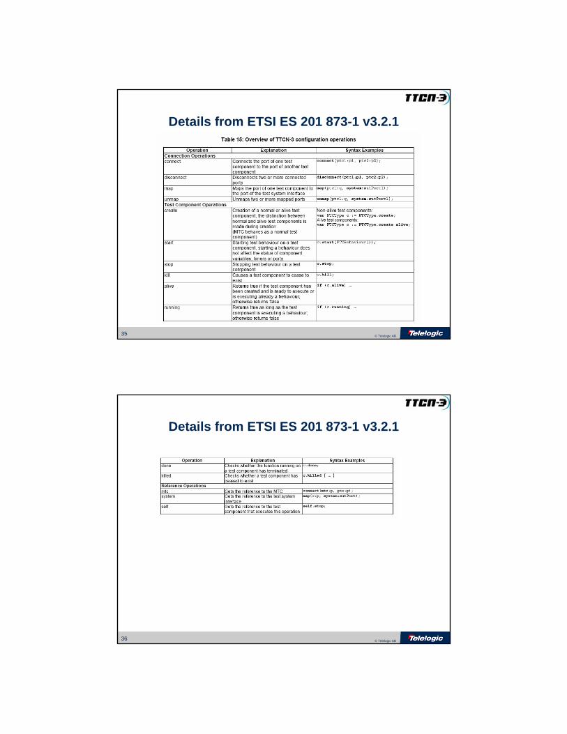
35 © Telelogic AB
Details from ETSI ES 201 873-1 v3.2.1
36 © Telelogic AB
Details from ETSI ES 201 873-1 v3.2.1

37 © Telelogic AB
Tips and Guidelines
• Common behavior must be defined in function function TS_SetupConnection()
runs on PTC1Type {
...
PCO1.send(msg1);
...
• Theses functions can be called by any other function running on the same component type.
• These function should be parameterized with the PCO and CP that they use.
function TS_SetupConnection(pco:PCOType)
runs on PTC1Type {
...
pco.send(msg1);
...
38 © Telelogic AB
Tips and Guidelines
• It is strongly recommended to check that the PTCs have finished their execution, with the use of the DONE statement in MTC, before terminating the MTC.
all component.done;
setverdict(pass);
stop;
39 © Telelogic AB
Tips and Guidelines
• There is no need to explicitly passed PTC verdicts to the MTC using coordination messages
– A global verdict is automatically maintained by the MTC– The global verdict is updated whenever a component terminates– Remember: Verdict never improve
– Make the TTCN-3 script more readable
40 © Telelogic AB
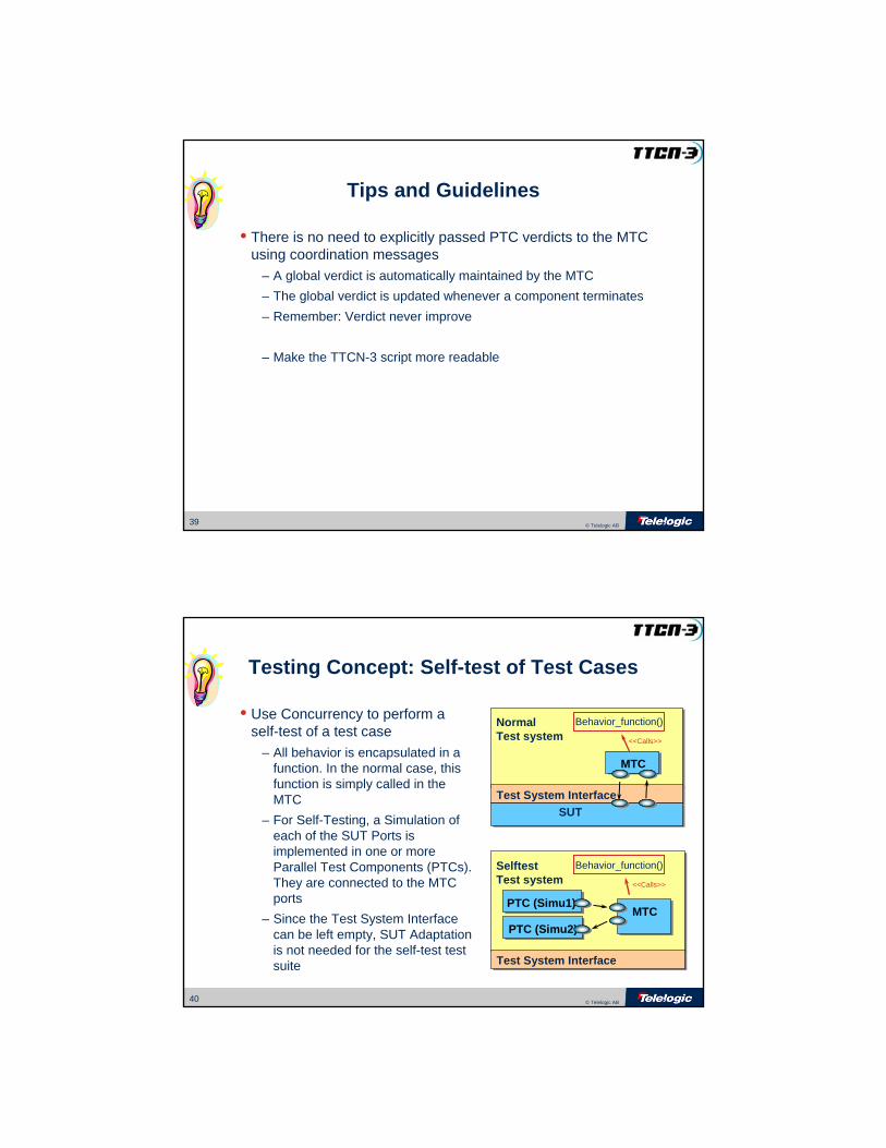
Testing Concept: Self-test of Test Cases
• Use Concurrency to perform a self-test of a test case
– All behavior is encapsulated in a function. In the normal case, this function is simply called in the MTC
– For Self-Testing, a Simulation of each of the SUT Ports is implemented in one or more Parallel Test Components (PTCs). They are connected to the MTC ports
– Since the Test System Interface can be left empty, SUT Adaptation is not needed for the self-test test suite
NormalTest system
MTC
Test System InterfaceTest System InterfaceSUT
Behavior_function()
<<Calls>>
SelftestTest system
Test System InterfaceTest System Interface
Behavior_function()
<<Calls>>
MTCPTC (Simu1)
PTC (Simu2)

41 © Telelogic AB
Benefits with Concurrent TTCN
• Less code to write
• Can have several test architectures in the same test suite
• Several service providers can be used
• Other components can be created at any time during the test case execution
• Concurrency– We can have several components executing simultaneously
– Several processes aiming at the same goal