Title Molecular Design of Silk Fibroin for Functional...
137
Title Molecular Design of Silk Fibroin for Functional Scaffolds( Dissertation_全文 ) Author(s) Kambe, Yusuke Citation Kyoto University (京都大学) Issue Date 2013-03-25 URL https://doi.org/10.14989/doctor.k17556 Right 許諾条件により要旨・本文は2014-01-18に公開 Type Thesis or Dissertation Textversion author Kyoto University
Transcript of Title Molecular Design of Silk Fibroin for Functional...

Title Molecular Design of Silk Fibroin for Functional Scaffolds(Dissertation_全文 )
Author(s) Kambe, Yusuke
Citation Kyoto University (京都大学)
Issue Date 2013-03-25
URL https://doi.org/10.14989/doctor.k17556
Right 許諾条件により要旨・本文は2014-01-18に公開
Type Thesis or Dissertation
Textversion author
Kyoto University

Molecular Design of Silk Fibroin for Functional Scaffolds
Yusuke KAMBE
2013

i
Contents
Chapter 1
Introduction of This Study ............................................................................... 1
1.1. Tissue engineering/regenerative medicine ...................................................................... 1
1.2. Articular cartilage ............................................................................................................ 2
1.2.1. Chondrocytes and their extracellular matrix ...................................................................... 3
1.2.2. Treatment methods for articular cartilage .......................................................................... 4
1.3. Cell–material adhesion ..................................................................................................... 5
1.3.1. Cell adhesion from physicochemical perspectives .............................................................. 6
1.3.2. Cell adhesion from biological perspectives ........................................................................ 7
1.4. Mechanical properties and mechanical environment of cells ....................................... 9
1.4.1. Cellular mechanical properties ........................................................................................... 9
1.4.2. Mechanical stimulation of cells ........................................................................................ 10
1.5. Basic fibroblast growth factor ....................................................................................... 10
1.6. Silk fibroin ....................................................................................................................... 11
1.6.1. Structure of a silk protein .................................................................................................. 11
1.6.2. Process to form various materials .................................................................................... 13
1.6.3. Fibroin as a biomaterial ................................................................................................... 14
1.6.4. Transgenic technique for silkworms ................................................................................. 14
1.7. Background and purpose of this study ......................................................................... 15
References .............................................................................................................................. 19
Chapter 2
Development of bFGF-Fused Silk Fibroin, Evaluation of Its Activity, and
Application as a Scaffold for Cartilage Regeneration ................................. 29
2.1. Introduction .................................................................................................................... 29
2.2. Materials and methods ................................................................................................... 31

ii
2.2.1. Construction of a vector carrying cDNA encoding bFGF-fused fibroin L-chain ............. 31
2.2.2. Generation of transgenic silkworms ................................................................................. 32
2.2.3. SDS-PAGE and Western blotting ....................................................................................... 33
2.2.4. Sample preparation ........................................................................................................... 34
2.2.4.1. Silk fibroin extracted from PSG ......................................................................... 34
2.2.4.2. Silk proteins extracted from cocoons .................................................................. 34
2.2.4.3. Degummed silk fibroin ...................................................................................... 36
4.2.4.4. Fibroin sponges made from the refolded fibroin aqueous solution ........................ 36
2.2.4.5. Fibroin sponges with the refolding treatment ...................................................... 37
2.2.5. Structure and elasticity of the fibroin sponge .................................................................... 38
2.2.6. Evaluation of cell-proliferative activity of bFGF-fused silk fibroin .................................. 38
2.2.6.1. WST-1 assay..................................................................................................... 38
2.2.6.2. LDH assay ....................................................................................................... 39
2.2.7. Chondrogenesis in/on the fibroin sponge .......................................................................... 40
2.2.8. Statistical analysis ............................................................................................................ 41
2.3. Results ............................................................................................................................. 41
2.3.1. SDS-PAGE and Western blotting ....................................................................................... 41
2.3.2. Structures and elasticity of fibroin sponges ...................................................................... 42
2.3.3. Cell-proliferative activity .................................................................................................. 44
2.3.3.1. Silk fibroin extracted from PSG (Process I) ........................................................ 44
2.3.3.2. Silk proteins extracted from cocoons (Process II) ................................................ 44
2.3.3.3. Aqueous solution of refolded silk fibroin (Process III) ......................................... 46
2.3.4.4. Sterilized fibroin sponges made from the refolded fibroin aqueous solution (Process
IV) .............................................................................................................................. 46
4.3.4.5. Fibroin sponges with the refolding treatment (Process V) .................................... 47
2.3.4. Chondrogenesis in fibroin sponges ................................................................................... 47
2.4. Discussion ........................................................................................................................ 49
2.5. Conclusions ..................................................................................................................... 52
References .............................................................................................................................. 53

iii
Chapter 3
Adhesive Force Behavior of Single ATDC5 Cells in Chondrogenic Culture
......................................................................................................................... 57
3.1. Introduction .................................................................................................................... 57
3.2. Materials and methods ................................................................................................... 59
3.2.1. ATDC5 cells and culture conditions.................................................................................. 59
3.2.2. Alcian blue staining .......................................................................................................... 59
3.2.3. Alizarin red S staining ....................................................................................................... 60
3.2.4. Real-time PCR analysis .................................................................................................... 60
3.2.5. Immunofluorescence staining of F-actin ........................................................................... 60
3.2.6. Evaluation of mechanical properties of single ATDC5 cells ............................................. 62
3.2.7. Y27632 treatment to ATDC5 cells ..................................................................................... 65
3.2.8. Statistical analysis ............................................................................................................ 67
3.3. Results ............................................................................................................................. 67
3.3.1. Differentiation of ATDC5 cells in chondrogenic culture ................................................... 67
3.3.2. Cell morphology ................................................................................................................ 69
3.3.3. Mechanical properties of single ATDC5 cells ................................................................... 70
3.3.4. Effects of the Y27632 treatment ........................................................................................ 72
3.4. Discussion ........................................................................................................................ 74
3.5. Conclusions ..................................................................................................................... 77
References .............................................................................................................................. 78
Chapter 4
Development of RGDS-Fused Silk Fibroin and Its Effects on Chondrocyte
Adhesion and Cartilage Synthesis ............................................................... 83
4.1. Introduction .................................................................................................................... 83
4.2. Materials and Methods .................................................................................................. 85
4.2.1. Construction of a vector carrying cDNA encoding L-RGDS×2 ....................................... 85
4.2.2. Generation of transgenic silkworms ................................................................................. 85

iv
4.2.3. SDS-PAGE and Western blotting ....................................................................................... 86
4.2.4. Preparation of plate substrates ......................................................................................... 87
4.2.5. Preparation of fibroin sponges.......................................................................................... 88
4.2.6. Measurement of surface properties of substrates .............................................................. 88
4.2.7. Scanning electron microscopy (SEM) ............................................................................... 89
4.2.8. Chondrocytes and cell seeding .......................................................................................... 89
4.2.9. Chondrocyte attachment to substrates and competitive inhibition with soluble RGD
peptides ....................................................................................................................................... 90
4.2.10. Apparatus and procedure for measuring adhesive force................................................. 91
4.2.11. Determination of cell spreading area .............................................................................. 91
4.2.12. Immunofluorescence staining of F-actin and vinculin .................................................... 91
4.2.13. Real-time PCR analysis .................................................................................................. 92
4.2.14. Evaluation of the number of cells attaching to fibroin sponges ...................................... 92
4.2.15. Histological evaluation of regenerated cartilage ........................................................... 94
4.2.16. Statistical analysis .......................................................................................................... 94
4.3. Results ............................................................................................................................. 94
4.3.1. SDS-PAGE and Western blotting ....................................................................................... 94
4.3.2. Surface properties of substrates ........................................................................................ 95
4.3.3. Observations of fibroin films by SEM and chondrocyte attachment ................................. 96
4.3.4. Effects of L-RGDS×2 fibroin dose on chondrocyte adhesive force and spreading area ... 98
4.3.5. Cell adhesive force ............................................................................................................ 98
4.3.6. Cell spreading area ......................................................................................................... 101
4.3.7. Cell morphology .............................................................................................................. 102
4.3.8. mRNA expression levels .................................................................................................. 102
4.3.9. SEM observation of fibroin sponges and initial cell number .......................................... 102
4.3.10. Histology findings ......................................................................................................... 104
4.4. Discussion ...................................................................................................................... 104
4.5. Conclusions ................................................................................................................... 109
References ............................................................................................................................ 110

v
Chapter 5
Summary and Conclusions ......................................................................... 117
5.1. Summary ....................................................................................................................... 117
5.2. Conclusions ................................................................................................................... 119
5.3. Perspectives ................................................................................................................... 121
5.4. Research achievements ................................................................................................ 122
5.4.1. Original Research Papers ............................................................................................... 122
5.4.2. Presentation at international conferences....................................................................... 123
5.4.3. Awards and other remarks .............................................................................................. 124
Acknowledgements ...................................................................................... 127

vi

Chapter 1 Introduction of This Study
1
Chapter 1
Introduction of This Study
This study has addressed the research and development of functional silk fibroin
scaffolds for articular cartilage tissue engineering. Transgenic silkworm technology was
used to design silk fibroin molecules in order to append new functions to fibroin
scaffold, and we evaluated biomechanical and biochemical characteristics of
chondrogenic cells grown on the scaffold. This study has been conducted with various
visions, methodologies, and materials, whose important keywords and concepts are
reviewed in Sections 1.1–1.6. At the end of this chapter (Section 1.7), the background
and purpose of this study are described.
1.1. Tissue engineering/regenerative medicine
Tissue engineering/regenerative medicine is “an interdisciplinary field that applies the
principles and methods of engineering and the life science toward the development of
biological substitutes that restore, maintain, or improve tissue function” [1], and its goal
is to create living, functional tissues to repair or replace tissues or organ function lost
due to age, disease, damage, or congenital defects [2]. According to Langer and Vacanti
[1], three general strategies had been adopted for the creation of new tissue as of 1993:
isolated cells or cell substitutes, tissue-inducing substances, and cells placed on or
within matrices. In that report, they reviewed studies which had conducted the
replacement of ectodermal (nervous system, cornea, and skin), endodermal (liver,

Chapter 1 Introduction of This Study
2
pancreas, and tubular structures), and mesodermal-derived tissue (cartilage, bone, and
muscle). Some of these studies including clinical trials were worked out by adopting
two or more of the three strategies. Eight years after the report, Fuchs et al. [3]
presented three concepts emerging in the field of tissue engineering: dynamic in vitro
culture systems (bioreactors), microfabrication technology to create vascularized tissues
and organs, and an appropriate multipotent, undifferentiated stem cell. These concepts
were important to guide the formation of tissue with certain structural and functional
characteristics, to fabricate larger tissues and organs, and to ensure needed cells prior to
transplantation, respectively. The last concept of the three has been being achieved by
the appearance of induced pluripotent stem (iPS) cells from adult human fibroblasts [4].
The iPS cells have a potential to differentiate into various types of cells and can be
ensured without ethical issues unlike human embryonic stem (ES) cells [5]. Once safety
issue is overcome, human iPS cells should be applicable in regenerative medicine [4].
However, regardless of this Nobel Prize-winning discovery, there are still many issues
to be resolved to achieve the extensive clinical application of regenerative medicine.
This is because cell source is only one factor in tissue engineering. To accomplish the
ultimate goal of functional neoorganogenesis for human use, the close, interdisciplinary
collaboration of surgeons, engineers, chemists, and biologists is required [3].
1.2. Articular cartilage
Articular cartilage is a connective tissue that covers the surfaces of epiphysis in
diarthrodial joints (Fig. 1.1) and has a layered structure (Fig. 1.2). In a
frequently-loaded environment in vivo, it plays mechanical functions: shock absorption
and lubrication. Histologically it is classified as a hyaline cartilage and consists of
specialized cells called chondrocytes and extracellular matrices (ECMs) which are
produced by the cells. Most of the tissue is composed of the ECMs, and there are no
blood vessels, no lymph channels, and no nervous systems.

Chapter 1 Introduction of This Study
3
Fig. 1.1. A schematic drawing of human knee articulation [6].
Fig. 1.2. Statified structure of articular cartilage tissue. The photograph represents a
cross-section of porcine articular cartilage stained by Toluidine blue [6].
1.2.1. Chondrocytes and their extracellular matrix
Chondrocytes are highly-differentiated mesenchymal cells and have an anchorage
dependency. Interactions between chondrocytes and substrates thus play an important
role in various activities of the cells, such as survival, proliferation, and differentiation.

Chapter 1 Introduction of This Study
4
When two-dimensionally cultured as e.g., on a culture dish, chondrocytes proliferate
well but tend to lose their chondrocgenic phenotype to dedifferentiate into
fibroblast-like cells [7-9]. On the other hand, when embedded in three-dimensional gels
such as collagen, the cells can maintain their phenotype and synthesize
cartilage-specific matrices [10-11] but their proliferation ability tends to be suppressed
[13]. Hence, chondrocytes change their phenotype to produce different matrices,
depending on their surrounding environment. For example, chondrocytes in intact
cartilage synthesize collagen type II, but dedifferentiated and calcified chondrocytes
produce collagens type I and type X, respectively.
Cartilage ECM is mainly composed of water (60–80% wet weight), collagens
(10–20% wet weight), and proteoglycans (10–15% wet weight) [14]. There are several
types of collagens in the ECM, such as type I, II, V, VI, IX, X, XI, and XIV.
Proteoglycan is a glycoprotein and consists of several subunits of glycosaminoglycans
(GAGs) which bind to a core protein. GAGs are classified into chondroitin sulfate,
dermatan sulfate, keratan sulfate, and hyaluronan. Most of the proteoglycans in cartilage
tissue are chondroitin sulfate proteoglycan, which are called aggrecan.
1.2.2. Treatment methods for articular cartilage
Articular cartilage has no blood vessels, no lymph channels, and no nervous systems
in physiological condition. Additionally, chondrocytes, which account for 5% wet
weight in cartilage tissue, lose their ability of proliferation with aging. Due to these
characteristics, the self-reparation of the tissue is especially slow [15,16].
Bone-marrow stimulation technique, which consists of multiple perforations,
abrasions, and micro-fractures, has been clinically practiced as a treatment method for
cartilage defects since 1950s [17]. In this treatment, subchondral bone at a cartilage
defect is broken to promote cartilage repair from bone marrow-derived cells and
cytokines. However, the defect is considered to be repaired with fibrocartilage, which is
different form hyaline cartilage.

Chapter 1 Introduction of This Study
5
Mosaicplasty is one of the treatment methods that are expected to repair the defect
with hyaline cartilage [18]. Several cylindrical osteochondral plugs from the less
weight-bearing area are harvested, and then they are inserted mosaically into drilled
tunnels in the defect. However, it is difficult to regenerate the smooth surface like intact
cartilage.
Autologous cell implantation, which is a tissue-engineered therapy, has been applied
to a clinical practice. Since the first report in 1994 [19], the improvement of the clinical
symptom by autologous chondrocyte implantation has been reported. In this method,
chondrocytes harvested from a patient are expanded to implant in the cartilage defect of
the patient. However, its effectiveness is still controversial, and its application is limited
to regional cartilage defects. Therefore, in order to apply the treatment to a widespread
defect, it is necessary to get a large amount of cells with chondrogenic phenotype.
Artificial joint replacement is generally conducted as a treatment for the wide range
of cartilage defects. Accordingly, this treatment can ease pain, maintaining the bearing
property and lubricity of the joint. However, in some cases reimplantation is required
depending on the postoperative course.
1.3. Cell–material adhesion
After cell suspension is seeded onto a material, following phenomena are considered
to occur [20]: (i) water and saline contact to the material and (ii) proteins in the solution
absorb onto the surface of the material. Then, (iii) cells bind to the proteins absorbed on
the material. Finally, (iv) the cells attach and spread on the surface (Fig. 1.3). The
phenomena (i) and (ii) can be described from physicochemical perspectives, while the
phenomena (iii) and (iv) can be mentioned from biological perspectives.
Chapter 1 Introduction of This Study
6
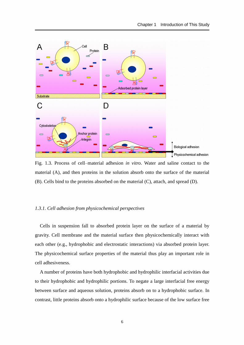
Fig. 1.3. Process of cell–material adhesion in vitro. Water and saline contact to the
material (A), and then proteins in the solution absorb onto the surface of the material
(B). Cells bind to the proteins absorbed on the material (C), attach, and spread (D).
1.3.1. Cell adhesion from physicochemical perspectives
Cells in suspension fall to absorbed protein layer on the surface of a material by
gravity. Cell membrane and the material surface then physicochemically interact with
each other (e.g., hydrophobic and electrostatic interactions) via absorbed protein layer.
The physicochemical surface properties of the material thus play an important role in
cell adhesiveness.
A number of proteins have both hydrophobic and hydrophilic interfacial activities due
to their hydrophobic and hydrophilic portions. To negate a large interfacial free energy
between surface and aqueous solution, proteins absorb on to a hydrophobic surface. In
contrast, little proteins absorb onto a hydrophilic surface because of the low surface free
Chapter 1 Introduction of This Study
7
energy. Therefore, the wettability of a material affects protein absorption and
hydrophobic interactions between cell membrane and the absorbed protein layer,
suggesting that it is involved in cell adhesion. There have been a lot of reports about the
relationship between the wettability and cell-adhesive activity of a material.
Accordingly, cells adhere effectively to surfaces that have moderate wettability with
water contact angles of 40–70°, but are not likely to adhere to extremely hydrophilic
and hydrophobic surfaces [21-25].
With respect to surface charge, electrostatic interactions via an electric double layer
are considered to have small influences in physiological salt concentrations [26], which
can be led by the Derjaguin-Landau-Verwey-Overbeek theory. Namely, cell–surface
distance that minimizes the interaction potential between the cell membrane and
material surface is small enough to neglect electrostatic repulsions. The distance is
6.3–6.7 nm, while the length of the extracellular part of a transmembrane cell-adhesive
molecule is apx. 20 nm. On the other hand, the surface charge affects the amount of
absorbed proteins [27], and it is reported that cells well adhere to the surface with
positive or negative charge [21,22,24,26].
Hydrogen bond and static repulsive force are also considered to affect cell
adhesiveness directly and/or via absorbed protein layer [28,29].
1.3.2. Cell adhesion from biological perspectives
Following to interactions between cell membrane and absorbed protein layer,
cell-adhesive proteins in the layer interact specifically with transmembrane
cell-adhesive molecules such as integrins. Below is the cell adhesion which can be
described from the biological perspectives.
Fibronectin is one of the main cell-adhesive proteins. The protein consists of two
subunits (apx. 250 kDa each), which are linked by a disulfide bond to form a dimer, and
each subunit chain is composed of type I, II, and III modules. These modules aggregate
to form function domains which bind to integrins, collagens, heparins, and fibrins [30].

Chapter 1 Introduction of This Study
8
There are domains celled ED-A, ED-B, and IIICS, whose expression is regulated by
alternative splicing. Their expressions thus result in the isoforms of the molecule.
Pierschbacher and Rouslahti [31] found that a peptide Arg-Gly-Asp-Ser (RGDS) is
the domain that is responsible for the cell-adhesive activity of the fibronectin. Because
the activity can be maintained when the serine is altered by other amino acid, the
minimum unit is RGD. This sequence is necessary for the cell-adhesive activity of
fibronetin, but is not a sufficient condition. To bind to cells, the peptides appeared to
form a structure where they can be recognized by receptors on cellular surface [31,32].
Integrins are transmembrane cell-adhesive proteins and function as receptors for
cell-adhesive molecules in ECM. The molecule consists of a chain (apx. 120–180
kDa) and a chain (apx. 90–110 kDa), which are noncovalently linked to form a
heterodimer. 19 types of subunits and 8 types of subunits are identified currently
[33], and ligand specificities derive from the combination of them. Integrin 51
recognizes an RGD sequence in fibronectin, vitronectin, and fibrin [34,35]. Both and
chains a single-pass transmembrane protein, and more than 90 percent of the molecule
is extracellular domains, which bind to ligand in ECM, while intercellular domains
Fig. 1.4. Schematic drawing of the cell–substrate adhesion mediated by integrins.

Chapter 1 Introduction of This Study
9
connect to cytoskeleton, mediated by anchor proteins such as talin, vinculin, and
-actinin (Fig. 1.4). Reportedly, cell–substrate adhesion via integrins activates almost
the same pathway as signals originated from cell growth factors. Integrins not only
mechanically bind a cell with substrates but also transfer information about the
surroundings of the cell into intracellular skeletal systems and signaling cascades. Thus,
they play an essential role in cellular adhesion, spreading, migration, survival,
proliferation, and differentiation.
1.4. Mechanical properties and mechanical environment of cells
Some types of cells are exposed to a mechanically-loaded environment in vivo. For
example, hemodynamic fluid shear stress acts on vascular endothelial cells, and
complex compression shear stress is loaded on articular chondrocytes. Cells can
recognize these mechanical stresses and change their behaviors, which thus has
motivated researchers to elucidate the mechanism itself and to use mechanical stimuli
for the effective tissue regeneration.
1.4.1. Cellular mechanical properties
Mechanical properties of cells are related to various cell behaviors such as cellular
shape, migration, growth, apoptosis, and differentiation. The properties have been
evaluated through a variety of techniques. Although information that can be obtained by
mechanical tests varies from method to method, cytoskeletal structure is one of the
major factors to affect the cellular mechanical properties. Typically, treatment with
cytochalasin D, which disrupt actin filaments, dramatically weakens cellular mechanical
properties [36,37]. Strength to detach a cell from a substrate has also been quantified,
which is defined as ‘cell adhesive force’. Besides the cytoskeleton, cell adhesive
constructions appear to affect the cell adhesive force [38-43]. For example, Yamamoto

Chapter 1 Introduction of This Study
10
et al. [38] measured the adhesive force of single murine fibroblasts L929 and showed
that the force is dependent on scaffold materials, explaining the number of bindings
(e.g., cytoskeleton–integrin, integrin–ligand, ligand–ligand, and ligand–material
surface) might determine the force. Although cellular mechanical properties have been
measured in numerous studies, what the properties represent and the precise mechanism
remain unclear.
1.4.2. Mechanical stimulation of cells
Mechanical stimuli for cells can promote their tissue regeneration and/or function
organization. In particular, mechanical stimulation of cells in osteocartilaginous tissues
have been studied a lot. For example, chondrocytes cultured stimulated by an
appropriate relative tribological movement generated more lubricative tissues than those
statically cultured [44]. Furthermore, an ultrasound stimulus has already been clinically
applied to fracture treatment due to its healing effects on fresh fractures and nonunions.
These physical stimuli are considered to be converted to intracellular signaling via
integrins. However, the effect of mechanical stimulation is still controversial and more
needs to be clarified.
1.5. Basic fibroblast growth factor
A growth factor is a naturally-occurring protein which binds to cell surface receptors,
and it can stimulate cellular growth, proliferation, and differentiation. Several growth
factor families have been identified, and their signaling cascades to stimulate cellular
behavior have also been elucidated.
Human basic fibroblast growth factor (bFGF) is a single-chain heparin-binding
polypeptide, which is generally composed of 155 amino acids and whose molecular
weight is apx. 18 kDa. This growth factor is synthesized by different types of cells and

Chapter 1 Introduction of This Study
11
is a potent mitogen for endothelial cells [45] and for mesodermal- and
neuroectodermal-derived cells [46,47]. For chondrogenic cells, it promotes cartilage
repair in vivo [48,49] and matrix production in vitro [50-52] when bFGF is used as an
additive to a solution such as culture medium.
bFGF is known as a notoriously unstable protein [53]. It is inactivated by treatments
with a variety of solvents such as dilute acid, organic solvents, and solutions of
guanidinium chloride [54]. Additionally, the growth factor exhibits an instability when
stored at room temperature, exposed to alkaline pH or incubated with caralytic amounts
of Cu2+
ions [55]. However, the stability of bFGF can increase when it binds to heparin
or heparin-analogue compounds [56-58].
Human bFGF has four cysteines, and the oxidation of cysteines 78 and 96
(numbering refers to the 155-amino acid form of human bFGF) results in the formation
of intermolecular disulphide bonds and multimerization, which cause the inactivation of
the growth factor [59-62]. This theory can be explained by reports showing that the
replacement of cysteines 78 and 96 by serines using site-directed mutagenesis
techniques avoided the multimerization and increased the stability of human bFGF
[53,55,60,62].
1.6. Silk fibroin
Below is an explanation about Bombyx mori silk proteins [63].
1.6.1. Structure of a silk protein
As shown in Fig. 1.5, the fiber from a silkworm cocoon forms a core-clad structure.
The core is fibroin protein, which mainly consists of the silk fiber, while the clad is
sericin protein. The latter protein is generally removed by a refinement process.
Fibroin protein consists of a heavy chain (H-chain; apx. 360 kDa) and a light chain

Chapter 1 Introduction of This Study
12
(L-chain; apx. 27 kDa), which are linked by a disulfide bond to form a heterodimer [64]
(Fig. 1.6). Six sets of the heterodimers are associated with one P25 protein by
hydrophobic interaction, and the whole is secreted from the posterior silk gland as a
high-molecular-weight elementary unit [65]. In the H-chain molecule, the long,
Fig. 1.5.Scanning electron microscopic image of a bave [63].
Fig. 1.6. Schematic drawing of a fibroin molecule.

Chapter 1 Introduction of This Study
13
extended, repeated region consists of a hydrophobic -sheet crystalline region
represented as (Gly-Ala-Gly-Ala-Gly-Ser/Tyr)n ((GAGAGS/Y)n). These regions are
linked by hydrophilic noncrystalline regions [66]. The molecular structure of the
H-chain is likely to contribute to the mechanical property, moisture-retaining property,
and drape of the silk fibers. On the other hand, the L-chain is considered to play a role
in fibroin secretion [67], but its relations to the structure and property of the silk fiber
have not yet been unclear.
1.6.2. Process to form various materials
To use silk proteins as a biomaterial, it is necessary to process to form various
configurations. The fibroin is insoluble in water and most of the organic solvents.
However, it is soluble in some particular organic solvents such as a calcium
chloride/ethanol-mixed solution and a high concentration of lithium bromide aqueous
solution. By dialyzing the fibroin solution against water, fibroin aqueous solution can be
obtained, which is a start point to process various materials.
A porous three-dimensional structure is important for use in materials as a scaffold
for tissue engineering. Several attempts to form a porous silk fibroin structure have been
reported [68], where a repeated freeze-dry process was adopted. However, it was
difficult to get high mechanical properties and to control spongy structures. Tamada [69]
reported a new process to form fibroin porous three-dimensional structure, which
involves freezing and thawing fibroin aqueous solution in the presence of a small
amount of an organic solvent. The resultant spongy structure has a high water content
requires as well as high mechanical properties. The solvent concentration, fibroin
concentration, freezing temperature, and freezing duration affect the sponge formation.
This fibroin structure can be autoclaved, and thus can be used as a biomaterial.

Chapter 1 Introduction of This Study
14
1.6.3. Fibroin as a biomaterial
Fibroin has been clinically practiced as a surgical suture. The silk suture has a high
clinical usability due to its ease to bind and the stability of its knots [70]. In addition,
reportedly, when refined and purified adequately, the silk fiber does not induce
inflammatory reactions [63,71-73].
Recently, the number of the studies using fibroin as a scaffold for tissue engineering
is increasing. Aoki et al. [13] reported that chondrocytes cultured using a porous silk
fibroin sponge can proliferate well and produce more sulfated GAG (sGAG), compared
to a collagen gel. Similarly, mesenchymal stem cells grown in a fibroin scaffold
synthesized a larger amount of sGAG and showed a higher collagen type II gene
expressions than those cultured in a collagen sponge [74].
1.6.4. Transgenic technique for silkworms
A transgenic technique for silkworms has already been established [75], which
enables the production of molecularly-designed silk proteins. Once a genetically
modified silkworm strain is developed, the modified fibroin can be produced
permanently. By using this method, it is possible to develop a fibroin with new
functions and mechanical properties (Fig. 1.7). Inoue et al. [76] mentioned several
advantages of the application of the transgenic silkworm as a bioreactor to produce
recombinant proteins such as that a large amount of a protein can be produced.
Moreover, the location of the recombinant protein can be designed, and the protein thus
can be immobilized to a particular part of the fibroin molecule. There have been several
studies of genetic modification of the H-chain [77], the L-chain [42,76,78-82], or P25
protein [83].

Chapter 1 Introduction of This Study
15
Fig. 1.7. Green fluorescent protein-fused silkworm cocoons under white light (A) and
near-ultraviolet light (B).
1.7. Background and purpose of this study
Cartilaginous tissues have an intrinsic lack of regenerative ability and when destroyed,
hyaline cartilage tissues never recovered spontaneously [16]. Osteroarthritis (OA) is one
of the most common forms of arthritis. As of 2004 the number of patients of OA was
estimated to be 24 million in Japan [84]. In addition, according to the National
Livelihood Survey in 2010 [85] reported by the Ministry of Health, Labour and Welfare,
Japan, arthritis is the number-four cause of being needed long-term care and also the
number-one cause of being needed support. Therefore, it is essential to advance
therapeutic treatments to improve and maintain the quality of life for people in the aging
society like Japan. Various treatments have been used to repair damaged cartilage
depending on the size of defects (Fig. 1.8). Cartilage tissue engineering, i.e., cell or
tissue transplantation, usually targets the damage with defects whose size is 2–6 cm2.
Just recently, autologous cultured cartilage called JACC® (Japan Tissue Engineering Co.,
Ltd., Japan) has been approved to sell in Japan by the Japanese government, which is
expected to progress the clinical application of cartilage regenerative medicine in Japan.

Chapter 1 Introduction of This Study
16
Fig. 1.8. Position of this study in the treatments for articular cartilage. Pictures and
graphics in this figure are quoted elsewhere [86-92].

Chapter 1 Introduction of This Study
17
However, there remain a lot of issues to be resolved. Due to the limitation of harvestable
chondrocytes, which have poor proliferative potential, the source of chondrogenic cells
needs to be secured. Recent advancement in the differentiation induction of iPS cells is
likely to achieve the differentiation of murine iPS cells into chondrocyte-like cells [93],
but their chondrogenic phenotype is still unclear. Additionally, 3-D structure and
mechanical functions of articular cartilage have to be repaired. Scaffold-free approaches
to form regenerate cartilage have been studied using cell sheet technology [94] or
bioreactors [95], while cellular scaffolds with new functions have been developed by
using chemical or physical modifications or post-conjugation techniques. These studies
have enabled to prepare regenerated cartilage with adequate mechanical properties and
effective chondrogenesis. However, the former approaches require a large number of
cells and specific culture devices and the latter ones are accompanied by technical
difficulties and high manufacturing costs.
Silk fibroin protein is FDA-approved and has been used in medicine for a wide
variety of applications such as surgical suture. Silk fibroin exhibits in-vitro and in-vivo
biocompatibilities [63,71-73], showing the same degree of inflammatory responses as
collagen [63]. Besides, fibroin molecules with a molecular weight of 40–120 kDa are
reported not to have antigenecities [96]. Although silk fibroin shows relatively slow
proteolytic biodegradation [97], which might limit the application range of the fibroin as
a biomaterial, it has robust mechanical properties including high mechanical modulus
and toughness [98]. The spongy structure of fibroin provides adjustable compressive
and tensile moduli superior to collagen sponge [63,69]. Unpublished observations have
shown that the silk fibroin spongy scaffold can be sutured to an affected site, covering
the whole articular surface of patella in a rabbit model. Therefore, there is a possibility
that silk fibroin sponge is used as a scaffold applicable to articular cartilage damage
with defects whose size is over 6 cm2. Furthermore, recent advances in transgenic
silkworm technology have made silk fibroin a novel biomaterial, in which recombinant
peptides or proteins can be located and combined in accordance with our design. These
features of silk fibroin can provide useful clues to resolve issues and to exceed the

Chapter 1 Introduction of This Study
18
technical limits of cartilage tissue engineering as shown in Fig. 1.8.
The final goal of this study is to develop useful, practical scaffolds which enable
effective cartilage regeneration (i.e., maintaining and/or improving the proliferative
ability and chondrogenic phenotype of cells). To accomplish this goal three purposes
have been set: to append promoting effects on cell proliferation to silk fibroin scaffold
(Chapter 2); to seek a design index alternative to bioactive macromolecules (Chapter 3);
and to add stimulatory effects on chondrogenesis by modulating the cell-adhesive
function of silk fibroin scaffold (Chapter 4). The molecular design of silk fibroin by
transgenic silkworm technology was applied to append new functions to the fibroin
scaffold as shown in Chapters 2 and 4. However, in Chapter 2, a macromolecular
growth factor was found to be difficult to exert its biological activity remarkably after
fabricated into 3-D porous scaffold. As cells are anchorage-dependent and change their
characteristics, such as mechanical and phenotypic properties, via cell–material
adhesion, cellular physical properties induced by cell adhesion can be an important
factor to design scaffold. Based on this viewpoint, cell adhesive force to scaffold
materials was quantified and its relations with chondrogenesis were discussed in
Chapters 3 and 4. This study would be expected to provide new, useful orientation in the
development of cellular scaffold for tissue engineering.

Chapter 1 Introduction of This Study
19
References
[1] Langer R, Vacanti JP. Tissue engineering. Science 1993;260:920-6.
[2] http://report.nih.gov/nihfactsheets/ViewFactSheet.aspx?csid=62&key=R (in Dec
2012)
[3] Fuchs JR, Nasseri BA, Vacanti JP. Tissue engineering: a 21st century solution to
surgical reconstruction. Ann Thorac Surg 2001;72:577-91.
[4] Takahashi K, Tanabe K, Ohnuki M, Narita M, Ichisaka T, Tomoda K, et al.
Induction of pluripotent stem cells from adult human fibroblasts by defined factors.
Cell 2007;131:861-72.
[5] Evans PM, Kaufman MH. Establishment in culture of pluripotential cells from
mouse embryos. Nature 1981;292:154-6.
[6] Yamamoto K. Functional expression and evaluation of tribological performances on
living tissue. 2006.
[7] Von der Mark K, Gauss V, Von der Mark H, Müller P. Relationship between cell
shape and type of collagen synthesised as chondrocytes lose their cartilage
phenotype in culture. Nature 1977;267:531-2.
[8] Benya PD, Shaffer JD. Dedifferentiated chondrocytes reexpress the differentiated
collagen phenotype when cultured in agarose gels. Cell 1982;30:215-24.
[9] Brodkin KR, García AJ, Levenston ME. Chondrocyte phenotypes on different
extracellular matrix monolayers. Biomaterials 2004;25:5929-38.
[10] Schuman L, Buma P, Versleyen D, de Man B, van der Kraan PM, van den Berg
WB, et al. Chondrocyte behaviour within different types of collagen gel in vitro.
Biomaterials 1995;16:809–14.
[11] Rahfoth B, Weisser J, Sternkopf F, Aigner T, von der Mark K, Brauer R.
Transplantation of allograft chondrocytes embedded in agarose gel into cartilage
defects of rabbits. Osteoarth Cart 1998;6:50–65.
[12] Gille J, Meisner U, Ehlers EM, Muller A, Russlies M, Behrens P. Migration pattern,
morphology and viability of cells suspended in or sealed with fibrin glue: a

Chapter 1 Introduction of This Study
20
histomorphologic study. Tissue Cell 2005;37:339–48.
[13] Aoki H, Tomita N, Morita Y, Hattori K, Harada Y, Sonobe M, et al. Culture of
chondrocytes in fibroin-hydrogel sponge. Biomed Mater Eng 2003;13:309-16.
[14] Woo S, Mow VC, Lai WM, Skalak R, Chien S. Handbook of Bioengineering. The
McGraw-Hill Company 1987.
[15] Buckwalter JA, Mankin HJ. Articular cartilage repair and transplantation. Arthritis
Rheum 1998;41:1331-42.
[16] Hunter W. Of the structure and diseases of articulating cartilages. Philos Trans
1743;470:514-21.
[17] Pridie KH. A method of resurfacing osteoarthritic knee joints. J Bone Joint Surg Br
1959;41:618-19.
[18] Matsusue Y, Yamamuro T, Hama H. Arthroscopic multiple osteochondral
transplantation to the chondral defect in the knee associated with anterior cruciate
ligament disruption. Arthroscopy 1993;9:318-21.
[19] Brittberg M, Lindahl A, Nilsson A, Ohlssion C, Isaksson O, Peterson L. Treatment
of deep cartilage defects in the knee with autologous chondrocyte transplantation. N
Engl J Med 1994;331:889-95.
[20] Iwata H. Biomaterials. Kyoritsu Shuppan Co., Ltd., 2005.
[21] Van Wachem PB, Hogt AH, Beugeling T, Feijen J, Bantjes A, Detmers JP, et al.
Adhesion of cultured human endothelial cells onto methacrylate polymers with
varying surface wettability and charge. Biomaterials 1987;8:323-8.
[22] Kishida A, Iwata H, Tamada Y, Ikada Y. Cell behaviour on polymer surfaces
grafted with non-ionic and ionic monomers. Biomaterials 1991;12:786-92.
[23] Tamada Y, Ikada Y. Cell adhesion to plasma-treated polymer surfaces. Polymer
1993;34:2208-12.
[24] Lee JH, Lee JW, Khang G, Lee HB. Interaction of cells on chargeable functional
group gradient surfaces. Biomaterials 1997;19:351-8.
[25] Arima Y, Iwata H. Effect of wettability and surface functional groups on protein
adsorption and cell adhesion using well-defined mixed self-assembled monolayers.

Chapter 1 Introduction of This Study
21
Biomaterials 2007;28:3074-82.
[26] Arima Y, Iwata H. Effects of surface functional groups on protein adsorption and
subsequent cell adhesion using self-assembled monolayers. J Mater Chem
2007;17:4079-87.
[27] Lestelius M, Liedberg B, Tengvall P. In vitro plasma protein adsorption on
-functionalized alkanethiolate self-assembled monolayers. Langmuir
1997;13:5900-8.
[28] Ostuni E, Chapman RG, Holmlin RE, Takayama S, Whitesides GM. A survey of
structure-property relationships of surface that resist the adsorption of protein.
Langmuir 2001;17:5605-20.
[29] Prime KL, Whitesides GM. Adsorption of proteins onto surfaces containing
end-attached oligo (ethylene oxide): a model system using self-assembled
monolayers. J Am Chem Soc 1993;115:10714-21.
[30] Hynes RO. Fibronectins. Springer-Verlag, 1990.
[31] Pierschbacher MD, Ruoslahti E. Cell attachment activity of fibronectin can be
duplicated by small synthetic fragments of the molecule. Nature 1984;309:30-4.
[32] Maeda T, Oyama R, Ichihara-Tanaka K, Kimizuka F, Sekiguchi K. A novel cell
adhesive protein engineered by insertion of the Arg-Gly-Asp-Ser tetrapeptide. J
Biol Chem 1989;264:15165-8.
[33] Humphries MJ. Integrin structure. Biochem Soc Trans 2000;28:311-39.
[34] Ruoslahti E, Pierschbacher MD. Arg-Gly-Asp: a versatile cell recognition signal.
Cell 1986;44:517-8.
[35] Hynes RO. Integrins: versatility, modulation, and signaling in cell adhesion. Cell
1992;69:11-25.
[36] Nagayama K, Nagano Y, Sato M, Matsumoto T. Effect of actin filament distribution
on tensile properties of smooth muscle cells obtained from rat thoracic aortas. J
Biomech 2006;39:293-301.
[37] Tan SCW, Pan WX, Ma G, Cai N, Leong KW, Liao K. Viscoelastic behaviour of
human mesenchymal stem cells. BMC Cell Biol 2008;9:40.

Chapter 1 Introduction of This Study
22
[38] Yamamoto A, Mishima S, Maruyama N, Sumita M. Quantitative evaluation of cell
attachment to glass, polystyrene, and fibronectin- or collagen-coated polystyrene by
measurement of cell adhesive shear force and cell detachment energy. J Biomedl
Mater Res 2000;50:114-24.
[39] Wu CC, Su HW, Lee CC, Tang MJ, Su FC. Quantitative measurement of changes
in adhesion force involving focal adhesion kinase during cell attachment, spread,
and migration. Biochem Biophys Res Commun 2005;329:256-65.
[40] Yamamoto K, Tomita N, Fukuda Y, Suzuki S, Igarashi N, Suguro T, et al.
Time-dependent changes in adhesive force between chondrocytes and silk fibroin
substrate. Biomaterials 2007;28:1838-46.
[41] Cai N, Wong CC, Tan SCW, Chan V, Liao K. Temporal effect of functional
blocking of 1 integrin on cell adhesion strength under serum depletion. Langmuir
2009;25:10939-47.
[42] Kambe Y, Yamamoto K, Kojima K, Tamada Y, Tomita N. Effects of RGDS
sequence genetically interfused in the silk fibroin light chain protein on
chondrocyte adhesion and cartilage synthesis. Biomaterials 2010;31:7503-11.
[43] Kambe Y, Takeda Y, Yamamoto K, Kojima K, Tamada Y, Tomita N. Effect of
RGDS-expressing fibroin dose on initial adhesive force of a single chondrocyte.
Biomed Mater Eng 2010;20:309-16.
[44] Yamamoto K, Takaya R, Tamada Y, Tomita N. Effects of tribological loading
history on the expression of tribological function of regenerated cartilage.
Tribology Online 2008;3:148-52.
[45] Shing Y, Folkman J, Sullivan R, Butterfield C, Murray J, Klagsbrun M. Heparin
affinity: purification of a tumor-derived capillary endothelial cell growth factor.
Science 1984;223:1296-99.
[46] Gospodarowicz D, Ferrara N, Schweigerer L, Neufeld G. Structural
characterization and biological functions of fibroblast growth factor. Endocrine Rev
1987;8:95-114.
[47] Burgess WH, Maciag T. The heparin-binding (fibroblast) growth factor family of

Chapter 1 Introduction of This Study
23
proteins. Ann Rev Biochem 1989;58:575-606.
[48] Cuevas P, Burgos J, Baird A. Basic fibroblast growth factor (FGF) promotes
cartilage repair in vivo. Biochem Biophys Res Commun 1988;156:611-8.
[49] Fujimoto E, Ochi M, Kato Y, Mochizuki Y, Sumen Y, IkutaY. Beneficial effect of
basic fibroblast growth factor on the repair of full-thickness defects in rabbit
articular cartilage. Arch Orthop Trauma Surg 1999;199:139-45.
[50] Schmal H, Zwingmann J, Fehrenbach M, Finkenzeller G, Stark GB, Südkamp NP,
et al. bFGF influences human articular chondrocyte differentiation. Cytotherapy
2007;9:184-93.
[51] Khan M, Palmer EA, Archer CW. Fibroblast growth factor-2 induced chondrocyte
cluster formation in experimentally wounded articular cartilage is blocked by
soluble Jagged-1. Osteoarthritis Cartilage 2010;18:208-19.
[52] Kim JH, Lee MC, Seong SC, Park KH, Lee S. Enhanced proliferation and
chondrogenic differentiation of human synovium-derived stem cells expanded with
basic fibroblast growth factor. Tissue Eng Part A 2011;17:991-1002.
[53] Estape D, Van den Heuvel J, Rinas U. Susceptibility towards intramolecular
disulphide-bond formation affects conformational stability and folding of human
basic fibroblast growth factor. Biochem J 1998;335:343-9.
[54] Westall FC, Rubin R, Gospodarowicz D. Brain-derived fibroblast growth factor: a
study of its inactivation. Life Sci 1983;33:2425-9.
[55] Caccia P, Nitti G, Cletini O, Pucci P, Ruoppolo M, Bertolero F, et al. Stabilization
of recombinant human basic fibroblast growth factor by chemical modifications of
cysteine residues. Eur J Biochem 1992;204:649-55.
[56] Gospodarowicz D, Cheng J. Heparin protects basic and acidic FGF from
inactivation. J Cell Physiol 1986;128:475-84.
[57] Vemuri S, Beylin I, Sluzky V, Stratton P, Eberlein G, Wang YJ. Characterization,
stability, and formulations of basic fibroblast growth factor. J Pharm Pharmacol
1994;46:484-6.
[58] Tardieu M, Bourin MC, Desgranges P, Barbier P, Barritault D, Caruelle JP.

Chapter 1 Introduction of This Study
24
Mesoglycan and sulodexide act as stabilizers and protectors of fibroblast growth
factors (FGFs). Growth Factors 1994;11:291-300.
[59] Thompson SA, Fiddes JC. Chemical characterization of the cysteines of basic
fibroblast growth factor. Ann N Y Acad Sci 1991;638:78-88.
[60] Fox GM, Schiffer SG, Rohde MF, Tsai LB, Banks AR, Arakawa T. Production,
biological activity, and structure of recombinant basic fibroblast growth factor and
an analog with cysteine replaced by serine. J Biol Chem 1988;263:18452-8.
[61] Iwane M, Kurosawa T, Sasada R, Seno M, Nakagawa T, Igarashi K. Expression of
cDNA encoding human basic fibroblast growth factor in E. coli. Biochem Biophys
Res Commun 1987;146:470-7.
[62] Seno M, Sasada R, Iwane M, Sudo K, Kurokawa T, Ito K et al. Stabilizing basic
fibroblast growth factor using protein engineering. Biochem Biophys Res Commun
1988;151:701-8.
[63] Tamada Y. Prospect of biomaterial study from insects. J Jpn Soc Biomater
2008;26:412-8.
[64] Tanaka K, Kajiyama N, Ishikura K, Waga S, Kikuchi A, Ohtomo K, et al.
Determination of the site of disulfide linkage between heavy and light chains of silk
fibroin produced by Bombyx mori. Biochim Biophys Acta 1999;1432:92-103.
[65] Inoue S, Tanaka K, Arisaka F, Kimura S, Ohtomo K, Mizuno S. Silk fibroin of
Bombyx mori is secreted, assembling a high molecular mass elementary unit
consisting of H-chain, L-chain, and P25, with a 6:6:1 molar ratio. J Biol Chem
2000;275:40517-28.
[66] Mita K, Ichimura S, James TC. Highly repetitive structure and its organization of
the silk fibroin gene. J Mol Evol 1994;38:583-92.
[67] Mori K, Tanaka K, Kikuchi Y, Waga M, Waga S, Mizuno S. Production of a
chimeric fibroin light-chain polypeptide in a fibroin secretion-deficient nalled pupa
mutant of the silkworm Bombyx mori. J Mol Biol 1995;251:217-28.
[68] Nazarov R, Jin HJ, Kaplan DL. Porous 3-D scaffolds from regenerated silk fibroin.
Biomacromolecules 2004;5:718-26.

Chapter 1 Introduction of This Study
25
[69] Tamada Y. New process to form a silk fibroin porous 3-D structure.
Biomacromolecules 2005;6:3100-6.
[70] Kadono K, Tamai S, Tomita N, Tmihata K. Handling characteristics of suture
materials. Jpn J Biomech 1999;20:261-5.
[71] Altman GH, Diaz F, Jakuba C, Calabro T, Horan RL, Chen J, et al. Silk-based
biomaterials. Biomaterials 2003;24:401-16.
[72] Panilaitis B, Altman GH, Chen J, Jin HJ, Karageorgiou V, Kaplan DL.
Macrophages responses to silk. Biomaterials 2003;24:3079-85.
[73] Meinel L, Hofmann S, Karageorgiou V, Kirker-Head C, Vunjak-Novakovic G,
Kaplan DL. The inflammatory responses to silk film in vitro and in vivo.
Biomaterials 2005;26:147-55.
[74] Wang Y, Kim UJ, Blasioli DJ, Kim HJ, Kaplan DJ. In vitro cartilage tissue
engineering with 3D porous aqueous-derived silk fibroin and mesenchymal stem
cells. Biomaterials 2005;26:7082-94.
[75] Tamura T, Thibert C, Royer C, Kanda T, Abraham E, Kamba M, et al. Germline
transformation of the silkworm Bombyx mori L. using a piggyBac
transposon-derived vector. Nat Biotechnol 2000;18:81-4.
[76] Inoue S, Kanda T, Imamura M, Quan GX, Kojima K, Tanaka H, et al. A fibroin
secretion-deficient silkworm mutant, Nd-sD, provides an efficient system for
producing recombinant proteins. Insect Biochem Mol Biol 2005;35:51-9.
[77] Kojima K, Kuwana Y, Sezutsu H, Kobayashi I, Uchino K, Tamura T, et al. A new
method for the modification of fibroin heavy chain protein in the transgenic
silkworm. Biosci Biotechnol Biochem 2007;71:2943-51.
[78] Tomita M, Munetsuna H, Sato T, Adachi T, Hino R, Hayashi M, et al. Transgenic
silkworms produced recombinant human type III procollagen in cocoons. Nat
Biotechnol 2003;21:52-6.
[79] Adachi T, Tomita M, Shimizu K, Ogawa S, Yoshizato K. Generation of hybrid
transgenic silkworms that express Bombyx mori prolyl-hydroxylase -subunits and
human collagens in posterior silk glands: production of cocoons that contained

Chapter 1 Introduction of This Study
26
collagens with hydroxylated proline residues. J Biotechnol 2006;126:205-19.
[80] Hino R, Tomita M, Yoshizato K. The generation of germline transgenic silkworms
for the production of biologically active recombinant fusion proteins of fibroin and
human basic fibroblast growth factor. Biomaterials 2006;27:5715-24.
[81] Yanagisawa S, Zhu Z, Kobayashi I, Uchino K, Tamada Y, Tamura T, et al.
Improving cell-adhesive properties of recombinant Bombyx mori silk by
incorporation of collagen of fibronectin derived peptides produced by transgenic
silkworms. Biomacromolecules 2007;8:3487-92.
[82] Sato M, Kojima K, Sakuma C, Murakami M, Aratani E, Takenouchi T, et al.
Production of scFv-conjugated affinity silk powder by transgenic silkworm
technology. PLoS one 2012;7:e34632.
[83] Royer C, Jalabert A, Da Rocha M, Grenier AM, Mauchamp B, Couble P, et al.
Biosynthesis and cocoon-export of a recombinant globular protein in transgenic
silkworms. Transgenic Res 2005;14:463-72.
[84] http://www.h.u-tokyo.ac.jp/vcms_lf/center22_rinsyo_undouki_19-21.pdf (in Dec
2012)
[85] http://www.mhlw.go.jp/toukei/saikin/hw/k-tyosa/k-tyosa10/4-2.html (in Dec 2012)
[86] http://aseed.coloplast.com/?bone=1 (in Dec 2012)
[87] http://www.northwaleskneeclinic.co.uk/images/mosaicplasty.jpg (in Dec 2012)
[88] http://www.engin.umich.edu/class/bme456/artjoint/artjoint.htm (in Dec 2012)
[89] http://www.knee-replacement-explained.com/KNEE-OSTEOTOMY.html (in Dec
2012)
[90] http://www.medicalexpo.com/prod/sartorius-group/autoclavable-bioreactors-69922-
450990.html (in Dec 2012)
[91] http://help.qgelbio.com/entries/188248-how-can-i-prevent-the-gels-from-sticking-to
-the-3d-disc-caster-when-harvesting (in Dec 2012)
[92] Sugiyama K, Okamura A, Kawazoe N, Tateishi T, Satp S, Chen G. Coating of
collagen on a poly(L-lactic acid) sponge surface for tissue engineering. Mater Sci
Eng C 2012;32:290-5.

Chapter 1 Introduction of This Study
27
[93] Diekman BO, Christoforou N, Willard VP, Sun H, Sanchez-Adams J, Leong KW, et
al. Cartilage tissue engineering using differentiated and purified induced pluripotent
stem cells. Proc Natl Acad Sci USA 2012. 10.1073/pnas.1210422109.
[94] Kaneshiro N, Sato M, Ishihara M, Mitani G, Sakai H, Mochida J. Bioengineered
chondrocyte sheets may be potentially useful for the treatment of partial thickness
defects of articular cartilage. Biochem Biophys Res Commun 2006;349:723-310
[95] Furukawa KS, Sato M, Nagai T, Ting S, Mochida J, Ushida T. Scaffold-free
cartilage tissue by mechanical stress loading for tissue engineering. Tissue Eng
(IN-TEC) 2009.
[96] Zhang YQ, Ma Y, Xia YY, Shen WD, Mao JP, Shirai K. Synthesis of silk
fibroin-insulin bioconjugates and their characterization and activities in vivo. J
Biomed Mater Res B Appl Biomater 2006;79:275-83.
[97] Horan RL, Antle K, Collette AL, Wang Y, Huang J, Chen J, et al. In vitro
degradation of silk fibroin. Biomaterials 2005;26:3385-93.
[98] Perez-Rigueiro J, Elices M, Llorca J, Viney C. Tensile properties of Argiope
trifasciata drag line silk obtained from the spider’s web. Appl Polym Sci
2001;82:2245-51.

Chapter 1 Introduction of This Study
28

Chapter 2 Development of bFGF-Fused Silk Fibroin, Evaluation of Its Activity, and Application as a Scaffold fro Cartilage Regeneration
29
Chapter 2
Development of bFGF-Fused Silk Fibroin,
Evaluation of Its Activity, and Application
as a Scaffold for Cartilage Regeneration
2.1. Introduction
To achieve the clinical application of regenerative medicine, the development of
functional scaffolds has been being addressed. Silk fibroin obtained through
degumming Bombyx mori (silkworm) silk was historically used as a surgical suture, and
various processes into cellular scaffolds such as a porous three-dimensional (3-D)
structure have been established [1-5]. In fact, silk fibroin has been widely studied as a
scaffold material for tissue regeneration such as bone [6-8], cartilage [9-13], and nerve
regeneration [14]. Moreover, physical and/or biological characteristics of silk fibroin
protein can be altered by chemical modification [15-18] or post-conjugation [6-8,10]
with functional factors. However, in the case of these modifications, the immobilization,
release, and/or loading efficiency of the functional factors can be controversial along
with technical difficulties and/or high manufacturing.
The establishment and progress of transgenic silkworm technology [19] have enabled
the production of silk fibroin proteins fused with recombinant proteins. Some of these
modified fibroins could maintain or recover new functions derived from the
recombinant protein even after a process into a material [13,20-23]. Yanagisawa et al.
[22] and we developed Arg-Gly-Asp (RGD)-fused silk fibroin and showed that more

Chapter 2 Development of bFGF-Fused Silk Fibroin, Evaluation of Its Activity, and Application as a Scaffold fro Cartilage Regeneration
30
cells attached to the cast film of the fibroin than that of wild-type fibroin. We also
manufactured a spongy structure of the RGD-fused fibroin as a scaffold for
chondrocytes and demonstrated the cells on the RGD-fused fibroin sponge effectively
formed the cartilage tissue [13]. Sato et al. [23] produced single-chain variable fragment
(scFv)-conjugated silk fibroin and showed the powder of the fibroin retained an affinity
to Wiskott-Aldrich syndrome protein, which is the target molecule of the scFv. Basic
fibroblast growth factor (bFGF)-fused silk fibroin was developed by Hino et al. [21].
They conducted refolding of the bFGF-fused fibroin and showed the modified fibroin
immobilized on a culture dish enhanced the growth of human umbilical vein endothelial
cells (HUVECs). These studies suggest that the silk fibroin fused with a functional
protein can be used as a biomaterial for scaffold-based tissue regeneration, and we
actually demonstrated that more cartilage-like tissues were synthesized in/on the
RGD-fused fibroin spongy scaffold than in/on the wild-type fibroin sponge. However,
in the case of the RGD-fused fibroin only eight amino-acid residues ((RGDS)2) are
fused with the fibroin protein, and it remains unclear whether a genetically-modified
fibroin fused with a macromolecular recombinant protein displays the function of the
recombinant protein even after fabricated into a 3-D scaffold.
In the present study, we have aimed to develop a silk fibroin scaffold with
cell-growth function for cartilage regeneration by using a transgenic silkworm strain
that produces silk fibroin protein fused with bFGF. This growth factor is reported to
promote cartilage repair in vivo [24,25] and chondrogenesis in vitro [26-28], showing
enhancement effects on the viability and/or matrix production of chondrogenic cells. In
the bFGF-fesed fibroin molecule, bFGF is designed to be linked to the fibroin light
chain (L-chain) protein through a linker with a collaganase-cleavage site. This cleavage
site is composed of amino acids, Pro-Leu-Gly-Ile-Ala-Gly (PLGIAG), which is cleaved
between the Gly and Ile by a collagenase: matrix metarlloproteinase 1 (MMP1) [29].
Thus, our strategy is that bFGF fused with the fibroin scaffold is to be released along
with cartilage metabolism. Using Western blot analysis, we confirmed that bFGF was
fused with the fibroin L-chain and could be released from the L-chain by a collagenase

Chapter 2 Development of bFGF-Fused Silk Fibroin, Evaluation of Its Activity, and Application as a Scaffold fro Cartilage Regeneration
31
treatment. Then, cell-proliferative activity of the bFGF-fused fibroin was investigated at
various stages in a process to form a silk fibroin spongy structure. Finally, we evaluated
the usefulness of the bFGF-fused fibroin sponge as a scaffold for cartilage tissue
engineering.
2.2. Materials and methods
2.2.1. Construction of a vector carrying cDNA encoding bFGF-fused fibroin L-chain
Two oligonucleotides (bFGF_col2link-5Bg2: 5'-GAGATCTCCACTAGGAATAGCA
GGAATG-3'; and bFGF_col2link-3: 5'-GATGCTCCCGGCTGCCATTCCTGCTATTC
-3') were mixed, and an oligonucleotide cassette (5'-GAGATCTCCACTAGGAATAG
CAGGAATGGCAGCCGGGAGCATC-3') was obtained by polymerase chain reaction
(PCR)-amplification. On the other hand, cDNA encoding 155-amino acid residue-long
human bFGF (accession number, J04513) was amplified by PCR from a cloned cDNA
encoding human bFGF provided elsewhere using two oligonucleotides (bFGF_ORF-5:
5'-ATGGCAGCCGGGAGCATCACC-3'; and bFGF_ORF-3SalI: 5'-GGTCGACTCAG
CTCTTAGCAGAC-3'). The two resultant oligonucleotide cassettes were annealed, and
cDNA encoding a bFGF with a collagenase cleavage site, PLGIAG, was obtained by
PCR using bFGF-col2link-5Bg2 and bFGF_ORF-3SalI. This amplified fragment was
treated with BglII and SalI and cloned between BamHI and SalI sites of pLC-vec. The
resultant plasmid was designated pLC-col2bFGF. To obtain a transfer plasmid, the
expression cassette in pLC-col2bFGF was digested with FseI and AscI, and, finally, the
resulting fragment was cloned between the FseI and blunt-ended AscI sites of
pBac(3×P3-DsRed2afm)E1 [20]. This transfer plasmid was designated
pBac(3×P3-DsRed2afm)E1_pLC-col2bFGF, whose structure is shown in Fig. 2.1.
Chapter 2 Development of bFGF-Fused Silk Fibroin, Evaluation of Its Activity, and Application as a Scaffold fro Cartilage Regeneration
32
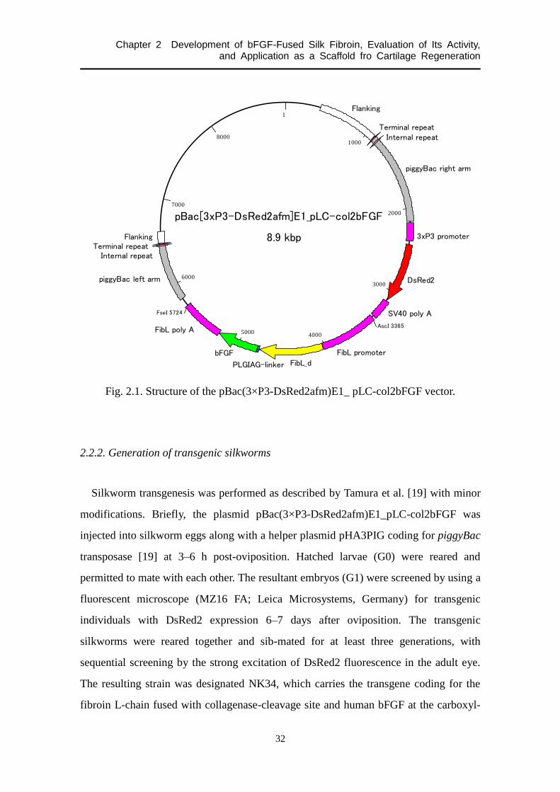
Fig. 2.1. Structure of the pBac(3×P3-DsRed2afm)E1_ pLC-col2bFGF vector.
2.2.2. Generation of transgenic silkworms
Silkworm transgenesis was performed as described by Tamura et al. [19] with minor
modifications. Briefly, the plasmid pBac(3×P3-DsRed2afm)E1_pLC-col2bFGF was
injected into silkworm eggs along with a helper plasmid pHA3PIG coding for piggyBac
transposase [19] at 3–6 h post-oviposition. Hatched larvae (G0) were reared and
permitted to mate with each other. The resultant embryos (G1) were screened by using a
fluorescent microscope (MZ16 FA; Leica Microsystems, Germany) for transgenic
individuals with DsRed2 expression 6–7 days after oviposition. The transgenic
silkworms were reared together and sib-mated for at least three generations, with
sequential screening by the strong excitation of DsRed2 fluorescence in the adult eye.
The resulting strain was designated NK34, which carries the transgene coding for the
fibroin L-chain fused with collagenase-cleavage site and human bFGF at the carboxyl-
1
1000
2000
3000
40005000
6000
7000
8000
pBac[3xP3-DsRed2afm]E1_pLC-col2bFGF
AscI 3365
FseI 5724
Flanking
piggyBac right arm
3xP3 promoter
DsRed2
SV40 poly A
FibL promoter
FibL_dPLGIAG-linker
bFGF
FibL poly A
piggyBac left arm
Flanking 8.9 kbp
Terminal repeatInternal repeat
Terminal repeatInternal repeat

Chapter 2 Development of bFGF-Fused Silk Fibroin, Evaluation of Its Activity, and Application as a Scaffold fro Cartilage Regeneration
33
terminus.
2.2.3. SDS-PAGE and Western blotting
Cocoon shells of wild-type or NK34 silkworms were diced into apx. 1 mm2. They
were suspended in an 8 M urea aqueous solution with 5% 2-mercaptoethanol (2ME) and
incubated at 80°C for 15 min with some stirrings, followed by washing with distilled
water prewormed at 80°C. This urea refinement procedure was repeated twice to
roughly remove sericin proteins. The rest silk proteins were dissolved in 9.0 M LiBr
aqueous solution by stirring at room temperature (RT) for 1 h. After centrifugation, the
supernatant was dialyzed against phosphate buffered saline (PBS, pH 7.4; Wako Pure
Chemical Industries Ltd., Japan) by using the EasySep (molecular weight cut off
(MWCO), 14,000; Tomy Seiko Co., Ltd., Japan) in accordance with the manufactures
instructions. Then the protein concentration was determined by the absorbance at
280-nm ultraviolet light and adjusted to 20 mg/3 ml with PBS, where different
concentrations of collagenase (Collagenase L; Nitta Gelatin Inc., Japan) were added
(final concentration, 4 mg/ml silk protein and 0, 0.4, 4, and 40 µg/ml collagenase). After
incubation at 37°C for 24 h, the resultant solutions were mixed with the equal volume of
the Laemmli Sample Buffer (Bio-Rad Laboratories Inc., USA) containing 5% 2ME and
incubated at 60°C for 20 min. 15 or 5 µl of the solution was applied to sodium dodecyl
sulfate-polyacrylamide gel electrophoresis (SDS-PAGE).
SDS-PAGE was performed on a Mini-PROTEAN TGX gel (Any kDTM
; Bio-Rad
Laboratories Inc.). Commercial recombinant human bFGF (rhbFGF; Wako Pure
Chemical Industries Ltd.) was also applied on the gel as a positive control. Separated
proteins were visualized by staining a gel with EzStain AQua (Atto Corp., Japan)
containing Coomassie brilliant blue (CBB). For immunoblotting, separated proteins on
another gel were transferred onto a polyvinylidene fluoride (PVDF) membrane
(Immun-Blot® PVDF Membrane for Protein Blotting; Bio-Rad Laboratories Inc.) by
using Trans-Blot®
SD Semi-Dry Transfer Cell (Bio-Rad Laboratories Inc.) and

Chapter 2 Development of bFGF-Fused Silk Fibroin, Evaluation of Its Activity, and Application as a Scaffold fro Cartilage Regeneration
34
subjected to Western blot assay with Chemi-Lumi One Super (Nacalai Tesque Inc.,
Japan) according to the manufacturer’s instructions. Signals were detected with an
LAS-3000 mini compact chemiluminescence system (Fujifilm Corp., Japan). Rabbit
anti-human bFGF polyclonal antibody (ab10420; Abcam plc., UK) and horseradish
peroxidase-conjugated goat anti-rabbit IgG polyclonal antibody (ab6721; Abcam plc.)
were used as the primary and the secondary antibodies, respectively.
2.2.4. Sample preparation
Processes to prepare samples for evaluation of the biological activity of the
bFGF-fused fibroin are shown in Fig. 2.2. These details are described below.
2.2.4.1. Silk fibroin extracted from PSG
Posterior silkglands (PSGs) was extracted from Bombyx mori wild-type C515 or
NK34 silkworms and immersed in solution A composed of 1.7 mM Na2HPO4, 16.7 mM
KH2PO4, 150 mM NaCl, 1 mM KCl, and 3 mM CaCl2 to extract fibroin proteins. The
solution was filtered through a paper membrane with 9.5-µm pores (#5B; Kiriyama
glass Co., Japan) and centrifuged at 9,100×g for 30 min at 4°C to remove impurities.
The fibroin solutions were sterilized by filtering through a polyethersulfone (PES)
membrane with 0.22-µm pores (Millipore Corp., USA). This procedure was designated
Process I, which is shown in Fig. 2.2.
2.2.4.2. Silk proteins extracted from cocoons
Cocoons of wild-type or NK34 silkworms were diced into apx. 5 mm square,
dissolved in a 9.0 M LiBr aqueous solution at RT for 6–10 h with stirring. Then, the
solution was dialyzed in water at 4°C using a cellulose dialysis membrane (Spectra/Por
1; MWCO, 6–8000; Spectrum Laboratories Inc., USA) for 3 days, changing the water
every 10–14 h. The resultant silk protein aqueous solution was sterilized by 0.22-µm

Chapter 2 Development of bFGF-Fused Silk Fibroin, Evaluation of Its Activity, and Application as a Scaffold fro Cartilage Regeneration
35
Fig. 2.2. Flowchart of a process to form a silk fibroin sponge and the evaluation points
of the cell-proliferative activity of the bFGF-fused fibroin (I–V).

Chapter 2 Development of bFGF-Fused Silk Fibroin, Evaluation of Its Activity, and Application as a Scaffold fro Cartilage Regeneration
36
filtering. Separately, in order to refold the bFGF fused with the fibroin L-chain, silk
proteins dissolved in 9.0 M LiBr were was subjected to a refolding process with the
serial dilution of urea and/or the glutathione redox system according to Hino et al. [21].
As a negative control, wild-type silk fibroin was also subjected to the refolding process.
Silk proteins in 9.0 M LiBr were dialyzed against 8 M urea in solution B composed of
50 mM Tris-HCl (pH 8.0) and 200 mM NaCl at 4°C for 10–14 h. The dialysate was
replaced with 4 M urea in solution C composed of 1.0 mM reduced glutathione (GSH),
0.1 mM oxidized glutathione (GSSG), 50 mM Tris-HCl (pH 8.0), and 200 mM NaCl,
and the solution was incubated at 4°C for 10–14 h. Such serial dilution of urea was
repeated until the concentration of urea became 0.5 M. Finally, the silk protein solution
was dialyzed against water three times at 4°C for 10–14 h each, following to the dialysis
against solution B. The resultant silk protein aqueous solution was sterilized by 0.22-µm
filtering. These procedures were designated Process II.
2.2.4.3. Degummed silk fibroin
Cocoons of wild-type or NK34 silkworms were chopped into apx. 5 mm squire and
boiled for 30 min in a 0.02 M Na2CO3 aqueous solution. They were then washed with
boiled water to remove sericin proteins. The degummed silk fibroin was dried in air at
50°C overnight and dissolved in a 9.0 M LiBr aqueous solution at RT for 6–10 h with
stirring. Then, the solution was dialyzed against 8 M urea/solution B at 4°C for 10–14 h
with a cellulose dialysis membrane (Spectra/Por 1; MWCO, 6–8000). Serial urea
dilution with the glutathione redox system was conducted similarly to Item 2.2.4.2. The
solution was finally dialyzed against water and sterilized by 0.22-µm filtering. This
procedure was designated Process III.
4.2.4.4. Fibroin sponges made from the refolded fibroin aqueous solution
The fibroin aqueous solution prepared from Process III in the dialysis membrane was
Chapter 2 Development of bFGF-Fused Silk Fibroin, Evaluation of Its Activity, and Application as a Scaffold fro Cartilage Regeneration
37
concentrated by standing in a dehydrator at RT. Insoluble portions were removed by
centrifugation at 20,000 rpm for 30 min at 4°C, and its concentration was determined by
a bicinchoninic acid (BCA) assay with fibroin protein standards. Dimethyl sulfoxide
(DMSO) was added gradually, with stirring, to the fibroin aqueous solution at the
determined volume depending on the final concentration of the fibroin (4.0% (wt/vol))
and DMSO (1.0%). The mixed solution was frozen at –20°C for 17 h and thawed at RT
to yield a sponge-like structure. The fibroin sponges were washed by immersion in
water to remove DMSO. Then the fibroin sponges were sterilized by autoclaving,
dry-heating, or -irradiation: Sponges were immersed in PBS and autoclaved at 121°C
and 2 hPa for 20 min; wet sponges were frozen at –80°C, dried using Freeze Dryer
(FDU-1100; Tokyo Rikakikai Co., Ltd., Japan), and incubated at 180°C for 30 min; and
wet sponges were freeze-dried as above and irradiated at RT with 25 kGy from a 60
Co.
This procedure was designated Process IV.
2.2.4.5. Fibroin sponges with the refolding treatment
Degummed wild-type or bFGF-fused fibroin fibers were prepared as described in
Item 2.2.4.3 and dissolved in 9.0 M LiBr. Then, the solution was dialyzed in water using
a cellulose dialysis membrane (Spectra/Por 1; MWCO, 6–8000) for 3 days, changing
the water every 10–14 h. The fibroin aqueous solution was used to prepared fibroin
sponge as described in Item 4.2.4.4. The fibroin sponges were autoclaved in PBS and
then incubated at 4°C for 10–14 h in 8 M urea/solution B. Half of the urea solution was
replaced with a buffer containing 2.0 mM GSH, 0.2 mM GSSG, 50 mM Tris-HCl (pH
8.0), and 200 mM NaCl (final concentration, 4 M urea, 1.0 mM GSH, 0.1 mM GSSG,
50 mM Tris-HCl (pH 8.0), and 200 mM NaCl). After the incubation at 4°C for 10–14 h,
half of the solution was changed with solution C. Such serial dilution of urea was
repeated until the concentration of urea became 0.5 M. The sponges were finally
incubated in PBS followed by the incubation in the solution B. All the buffer solutions
were filtered through the PES membrane with 0.22-µm pores. This procedure was

Chapter 2 Development of bFGF-Fused Silk Fibroin, Evaluation of Its Activity, and Application as a Scaffold fro Cartilage Regeneration
38
designated Process V.
2.2.5. Structure and elasticity of the fibroin sponge
Scanning electron microscopy (SEM) and compression test were used to evaluate the
effect of the genetic modification on the topology and mechanical properties of fibroin
sponges, respectively. Three different samples were used for these experiments (n =3).
For the structure observation, the wild-type and bFGF-fused fibroin sponges
with/without the refolding prepared through Process V were roughly dehydrated by
placing on gauze. Following this, the dried fibroin sponges were imaged by a scanning
electron microscope (TM-1000; Hitachi Ltd., Japan).
The sponges with/without the refolding were use for a mechanical test. By using the
EZ test (Shimadzu Corp., Japan) with a 10-N load cell and an 8-mm-diameter load plate,
the compressive modulus was determined at an initial 0.1–0.2 strain of 1.5-mm
thickness samples. The head speed was 5.0 mm/min. This test was performed at RT.
2.2.6. Evaluation of cell-proliferative activity of bFGF-fused silk fibroin
The activity of bFGF fused with the L-chain was evaluated in a various phase of the
process to form a fibroin sponge as shown in Fig. 2.2: posterior silkgland (PSG)
(Process I), cocoons (Process II), fibroin solution (Process III), and fibroin sponge
(Processes IV and V).
2.2.6.1. WST-1 assay
A WST-1 assay was conducted to evaluate the activity of the bFGF-fused fibroin
solutions prepared from Processes I, II, and III. The concentration of the solutions was
determined by a BCA assay with fibroin protein standards. The murine fibroblast line
NIH3T3 provided by RIKEN BRC through the National Bio-Resource Project of
MEXT, Japan were seeded onto wells of 96-well tissue culture plate (Asahi Glass Co.,

Chapter 2 Development of bFGF-Fused Silk Fibroin, Evaluation of Its Activity, and Application as a Scaffold fro Cartilage Regeneration
39
Ltd., Japan) at a concentration of 2.0 × 10³ cells/well and cultured with Eagle’s MEM
(Nissui Parmaceutical Co., Ltd., Japan) supplemented with 10% fetal bovine serum
(FBS; Gibco Invitrogen Co., USA), 10 ng/ml kanamycin (Gibco Invitrogen Co.) for
antibiotics, 0.2% sodium bicarbonate (Gibco Invitrogen Co.), and 2 mM L-glutamin
(Gibco Invitrogen Co.) at 37°C in a humidified atmosphere of 95% air and 5% CO2.
After incubation for 24 h, the medium was replaced with Eagle’s MEM containing 1%
FBS, 10 ng/ml kanamycin, 0.2% sodium bicarbonate, 2 mM L-glutamin, 10 µg/ml
heparin, and different amounts of silk proteins or fibroin, and the cells were cultured for
48 h. Instead of silk proteins or fibroin, rhbFGF was added to the 1% FBS medium as a
positive control. Then, the cells were incubated with WST-1 reagent (Roche Diagnostics,
Germany) for 2 h, followed by the absorbance measurement at 450 nm using a plate
reader (VersaMaxTM
; Molecular Device LLC, USA). The absorbance at 650 nm was
used as a reference. The number of measurements in the wild-type, bFGF-fused, and
rhbFGF groups was n = 4, 4, and 3, respectively.
2.2.6.2. LDH assay
A lactate dehydrogenase (LDH) assay [30] was conducted to measure the activity of
bFGF-fused fibroin fibers and sponges prepared from Processes IV and V. NIH3T3 cells
were seeded onto the fibroin sponge scaffold at a concentration of 1.0 × 10⁴ and 2.0 ×
104 cells/scaffold (diameter, 6 and 8 mm, respectively; thickness, 1.5 mm) and cultured
with the Eagle’s MEM supplemented with 1% FBS, 10 ng/ml kanamycin, 0.2% sodium
bicarbonate, 2 mM L-glutamin, and 10 µg/ml heparin. Cell density in the fibroin
sponges was quantified by the LDH assay after culturing for 1, 3, and 5 days or 3, 7,
and 10 days. Samples were incubated in 0.5% Triton X-100 (9690T; Research Organics,
Inc., USA) in PBS solution at 4°C to dissolve the cells, and the LDH activity of the
solution was measured using the kinetics of NADH-consuming reactions at 340 nm
absorbance. The cell number was calculated using the LDH activity with calibration.
The medium was changed every 2 days. The number of measurements in each group

Chapter 2 Development of bFGF-Fused Silk Fibroin, Evaluation of Its Activity, and Application as a Scaffold fro Cartilage Regeneration
40
was n = 3.
2.2.7. Chondrogenesis in/on the fibroin sponge
Chondrocytes were prepared as described previously [9]. Briefly, articular cartilage
tissues were aseptically harvested from the proximal humerus, distal femur and
proximal tibia of 4-week-old Japanese white rabbits (Oriental Bio Service Co., Ltd.,
Japan). Chondrocytes were isolated via enzymatic digestion. After obtaining a
single-cell suspension, the cells were cultured to 80% confluence on a T-flask (Asahi
Glass Co., Ltd., Japan) with Dulbecco’s modified Eagle’s Medium (DMEM) (Nacalai
Tesque Inc.) containing 10% FBS (Nacalai Tesque Inc.) and 1% antibiotic mixture
(10,000 units/ml penicillin, 10,000 µg/ml streptomycin, and 25 µg/ml amphotericin B)
(Nacalai Tesque Inc.) at 37°C in a humidified atmosphere of 95% air and 5% CO2 for 5
to 7 days. The medium was changed every 2 or 3 days.
After expansion in culture, chondrocytes were removed from the flask by mixing
with 0.25% trypsin-EDTA (Nacalai Tesque Inc., Japan) and washed twice with PBS.
Then the chondrocytes were seeded onto the fibroin sponge scaffold prepared from
Process V (diameter, 6 mm; thickness, 1.5 mm) at a concentration of 1.0 × 10⁵
cells/scaffold, they were cultured with Dulbecco’s modified Eagle’s Medium (DMEM)
(Nacalai Tesque Inc.) containing 2% FBS and 10 ng/ml kanamycin at 37°C in a
humidified atmosphere of 95% air and 5% CO2 for 1, 3, and 5 days. Half of the medium
was changed every 2 days.
All the animal experiments followed the Regulation on Animal Experimentation at
Kyoto University, and were approved by the Animal Research Committee at Kyoto
University.
The number of chondrocytes in the fibroin sponge was determined by the LDH assay
as described in Item 4.2.5.3. On the other hand, the amount of sulfated
glycosaminoglycan (sGAG) content in the samples was assayed using the
1,9-dimethylmethylene blue (DMMB) method [31]. As described previously [32], each

Chapter 2 Development of bFGF-Fused Silk Fibroin, Evaluation of Its Activity, and Application as a Scaffold fro Cartilage Regeneration
41
chondrocyte-fibroin construct was digested with 1.5 ml of 24 mg/ml papain solution in
PBS at 60°C for 1 h. The sample solution was mixed with a DMMB solution, and the
absorbance at 530 nm was measured by the plate reader. The amount of sGAG in each
sample was calculated using a standard curve calibrated by using a solution of
chondroitin sulfate C sodium salt (Nacalai Tesque, Inc.). The number of measurements
in each group was n = 3.
2.2.8. Statistical analysis
Two-way ANOVA was used to analyze effects of the type of fibroins and the
refolding treatment on the mechanical properties of fibroin sponges, effects of the type
of fibroins and the fibroin concentration on cell-proliferative activity, and effects of the
type of fibroins and culture period on cell number and on sGAG production, followed
by Tukey test for post hoc comparisons. A value of p < 0.05 was considered significant.
2.3. Results
2.3.1. SDS-PAGE and Western blotting
Proteins extracted from silk fibers of wild-type and NK34 silkworms were reacted
with different concentrations of collagenase, separated by SDS-PAGE, and
immunoblotted with anti-bFGF antibodies (Fig. 2.3). On CBB-stained gels, no band was
detected at the position corresponding to the predicted size (MW, apx. 45 kDa) of
bFGF-fused fibroin L-chain (A). However, as shown in Fig. 2.3B, such bands were
clearly observed on Western blot for the silk fibers of the NK34 silkworms but not for
those of the wild-type silkworms. Additionally, another band was detected on the lanes
of the collagenase-treated NK34 groups. The band was at the position of monomer
bFGF (MW, apx. 18 kDa), which was confirmed by the comparison to the positive
control.

Chapter 2 Development of bFGF-Fused Silk Fibroin, Evaluation of Its Activity, and Application as a Scaffold fro Cartilage Regeneration
42
2.3.2. Structures and elasticity of fibroin sponges
Figure 2.4 shows the representative scanning electron micrographs for the wild-type
and bFGF-fused fibroin sponges with/without the refolding treatment. The samples
were prepared via Process V. All of the sponges appeared to be similar in their
morphology, possessing similar pore size, pore structure, and pore size distribution.
Compressive elastic modulus of the wild-type and bFGF-fused fibroin sponges after
Fig. 2.3. SDS-PAGE (A) and Western blotting (B) of proteins extracted from the
wild-type (WT) and NK34 transgenic silk fibers. 4 mg/ml of the proteins were
incubated with 0 (a, e), 0.4 (b, f), 4 (c, g), 40 (d, h) µg/ml of collagenase. 30 or 10 µg of
the silk proteins were loaded on each lane of gels for CBB staining or immnoblotting,
respectively. 0.2 (i) and 2 (j) µg/ml of commercial rhbFGF solutions were used as the
positive control (PC). 15 or 5 µl of the PC solutions were used for CBB staining or
Western blotting, respectively. Novex® Sharp Protein Standard (Invitrogen Corp., USA)
was used as a marker (M1), while MagicMarkTM
XP Western Protein Standard
(Invitrogen Corp.) was used as another marker (M2). Arabic numerals at the left side of
the photographs are molecular weight in kDa.

Chapter 2 Development of bFGF-Fused Silk Fibroin, Evaluation of Its Activity, and Application as a Scaffold fro Cartilage Regeneration
43
Process V are summarized in Table 2.1. Although the refolding treatment tended to
decrease the mechanical property of the fibroin sponges, two-way ANOVA showed that
both factors (type of fibroin and with/without the refolding) did not affect the elastic
modulus of the sponges.
Fig. 2.4. Scanning electron micrographs of wild-type and bFGF-fused fibroin sponges
with/without the refolding treatment. Scale bar = 500 and 200 µm for 200- and 500-fold
magnifications, respectively.
Table 2.1. Compressive elastic modulus of each type of fibroin sponges with or without
the refolding treatment.
Fibroin sponges Without refolding [kPa] With refolding [kPa]
Wild-type 10.5 ± 1.4 9.4 ± 0.4
bFGF-fused 10.7 ± 0.3 9.5 ± 0.6
Data is shown in the form: mean ± SD. Three different samples in each group were used
to determine the compressive elastic modulus of the each group. No significant
differences were detected by two-way ANOVA-test.

Chapter 2 Development of bFGF-Fused Silk Fibroin, Evaluation of Its Activity, and Application as a Scaffold fro Cartilage Regeneration
44
2.3.3. Cell-proliferative activity
2.3.3.1. Silk fibroin extracted from PSG (Process I)
The dose-dependent changes in the absorbance reflecting cell number is shown in Fig.
2.5. As the concentration of rhbFGF increased, the absorbance also increased, indicating
that the proliferation of the NIH3T3 cells was stimulated by the growth factor. In
comparison to the wild-type group, the bFGF-fused group demonstrated significantly
higher absorbance at the concentration of 200 µg/ml.
2.3.3.2. Silk proteins extracted from cocoons (Process II)
Figure 2.6 shows the cell-proliferative activity of silk proteins from cocoons with (B)
Fig. 2.5. Dose-dependent changes in cell-proliferative activity of wild-type and
bFGF-fused fibroin solutions extracted from PSG of wild-type and NK34 silkworms,
respectively. Commercial rhbFGF solutions were used as the positive control. Data is
shown in the form: mean ± SD. Asterisks indicate significant differences between the
wild-type and bFGF-fused groups (***: p < 0.001; Tukey test following to two-way
ANOVA).

Chapter 2 Development of bFGF-Fused Silk Fibroin, Evaluation of Its Activity, and Application as a Scaffold fro Cartilage Regeneration
45
or without (A) the refolding treatment with the glutathione redox system. Without the
refolding treatment, there were no statistical differences in cell numbers between the
wild-type and bFGF-fused groups as shown in Fig. 2.6A. Meanwhile, with the refolding
treatment, the absorbance of the bFGF-fused group was statistically higher than that of
the wild-type group at 100 µg/ml.
Fig. 2.6. Dose-dependent changes in cell-proliferative activity of silk protein solutions
prepared from cocoons of wild-type and NK34 silkworms, including wild-type and
bFGF-fused fibroin proteins, respectively. The solutions were treated with (B) or
without (A) the refolding with glutathione system. Commercial rhbFGF solutions were
used as the positive control. Data is shown in the form: mean ± SD. Asterisks indicate
significant differences between the wild-type and bFGF-fused groups (***: p < 0.001;
Tukey test following to two-way ANOVA).

Chapter 2 Development of bFGF-Fused Silk Fibroin, Evaluation of Its Activity, and Application as a Scaffold fro Cartilage Regeneration
46
2.3.3.3. Aqueous solution of refolded silk fibroin (Process III)
Figure 2.7 shows the cell-proliferative activity of the refolded silk fibroin in aqueous
solution. Two-way ANOVA demonstrated that the type of fibroin affected the growth (p
< 0.001), and post-hoc Tukey comparison showed that the cell-proliferative activity of
the bFGF-fused group was significantly higher than that of the wild-type group.
2.3.4.4. Sterilized fibroin sponges made from the refolded fibroin aqueous solution
(Process IV)
The time-dependent changes in the number of NIH3T3 cells seeded onto the
wild-type and bFGF-fused fibroin sponges sterilized by autoclaving, dry-heating, or
-irradiation are shown in Fig. 2.8. 1.0 × 10⁴ cells were seeded onto a fibroin sponge
scaffold (diameter, 6 mm; thickness, 1.5 mm). Regardless of sterilization methods, there
were no statistical differences between the wild-type and bFGF-fused groups.
Fig. 2.7. Dose-dependent changes in cell-proliferative activity of degummed wild-type
and bFGF-fused fibroin solutions with the refolding process. Commercial rhbFGF
solutions were used as the positive control. Data is shown in the form: mean ± SD.
Asterisks indicate significant differences between the wild-type and bFGF-fused groups
(**: p < 0.001; Tukey test following to two-way ANOVA).
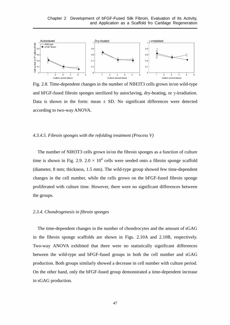
Chapter 2 Development of bFGF-Fused Silk Fibroin, Evaluation of Its Activity, and Application as a Scaffold fro Cartilage Regeneration
47
Fig. 2.8. Time-dependent changes in the number of NIH3T3 cells grown in/on wild-type
and bFGF-fused fibroin sponges sterilized by autoclaving, dry-heating, or -irradiation.
Data is shown in the form: mean ± SD. No significant differences were detected
according to two-way ANOVA.
4.3.4.5. Fibroin sponges with the refolding treatment (Process V)
The number of NIH3T3 cells grown in/on the fibroin sponges as a function of culture
time is shown in Fig. 2.9. 2.0 × 10⁴ cells were seeded onto a fibroin sponge scaffold
(diameter, 8 mm; thickness, 1.5 mm). The wild-type group showed few time-dependent
changes in the cell number, while the cells grown on the bFGF-fused fibroin sponge
proliferated with culture time. However, there were no significant differences between
the groups.
2.3.4. Chondrogenesis in fibroin sponges
The time-dependent changes in the number of chondrocytes and the amount of sGAG
in the fibroin sponge scaffolds are shown in Figs. 2.10A and 2.10B, respectively.
Two-way ANOVA exhibited that there were no statistically significant differences
between the wild-type and bFGF-fused groups in both the cell number and sGAG
production. Both groups similarly showed a decrease in cell number with culture period.
On the other hand, only the bFGF-fused group demonstrated a time-dependent increase
in sGAG production.

Chapter 2 Development of bFGF-Fused Silk Fibroin, Evaluation of Its Activity, and Application as a Scaffold fro Cartilage Regeneration
48
Fig. 2.9. Time-dependent changes in the number of NIH3T3 cells grown in/on wild-type
and bFGF-fused fibroin sponges with the refolding treatment. Data is shown in the
form: mean ± SD. No significant differences were detected according to two-way
ANOVA.
Fig.2.10. Time-dependent changes in the number chondrocytes (A) and the amount of
sGAG (B) in/on wild-type and bFGF-fused fibroin sponges with the refolding treatment.
Data is shown in the form: mean ± SD. No significant differences were detected
according to two-way ANOVA.

Chapter 2 Development of bFGF-Fused Silk Fibroin, Evaluation of Its Activity, and Application as a Scaffold fro Cartilage Regeneration
49
2.4. Discussion
By using transgenic silkworm technology, here we designed and developed
bFGF-fused silk fibroin in order to use it as a scaffold material for chondrogenic cells.
Fibroin protein consists of a heavy chain (H-chain; MW, apx. 360 kDa) and an L-chain
(MW, apx. 27 kDa), which are linked by a disulfide bond to form a heterodimer [33].
The modified fibroin molecule in this study was designed to have a bFGF at the
carboxyl terminal of the L-chain. Additionally, 6 amino-acid residues PLGIAG, which
is a collagenase-cleavage site [29], are introduced between the L-chain and the bFGF so
that the growth factor can be released from fibroin molecule by collagenase. Western
blot assay as shown in Fig. 2.3 demonstrated that fibroin proteins extracted from
cocoons of NK34 silkworms had bFGF-positive molecules, whose MW was about 42
kDa. As the MW of bFGF is apx. 18 kDa, a bFGF was successfully fused with the
L-chain by transgenic silkworm technology (L-chain 27 kDa + bFGF 18 kDa = 45 kDa).
Furthermore, the Western blot assay presented this bFGF could be released from the
L-chain by a collagenase treatment. These results suggest that we successfully generated
the transgenic silkworms which produced the bFGF-fused fibroin in accordance with
our design.
bFGF is an unstable protein; it is inactivated when stored at RT [34] and treated with
a variety of solvents, including dilute acid, organic solvents and solutions of
guanidinium chloride [35]. Therefore, bFGF fused with fibroin L-chain would be
denatured through the process to form a 3-D spongy structure of the fibroin, including
degumming, solubilization, dialysis, condensation, freezing with DMSO, and
sterilization. As can be seen in Fig. 2.5, bFGF-fused fibroin extracted from PSG
stimulated the proliferation of NIH3T3 cells, suggesting that the bFGF fused with the
L-chain secreted from PSG retains its biological activity. Meanwhile, Fig. 2.6A shows
that the bFGF-fused fibroin in silk proteins extracted from cocoons had no effects on
cell proliferation. Since the spinning of silk fibers accompanies conformational changes
in silk proteins and exposure to alkaline pH inactivates bFGF [34], spinning and/or

Chapter 2 Development of bFGF-Fused Silk Fibroin, Evaluation of Its Activity, and Application as a Scaffold fro Cartilage Regeneration
50
dissolution in 9.0 M LiBr aqueous solution whose pH is 9.56 ± 0.2 [36] could cause the
denaturation of the bFGF fused with the L-chain. However, the inactivated bFGF was
reactivated by a refolding process with a glutathione redox system as shown in Fig.
2.6B, which also recovered the cell-proliferative activity of the degummed bFGF-fused
fibroin as can be seen in Fig.2.7. Hino et al. [21] reported that the refolding with the
glutathione redox system restored the biological activity of another type of bFGF-fused
fibroin (r(FL/bFGF)nF) which was degummed with trypsin and solubilized in a solution
containing CaCl2, ethanol, and water. Although they referred treatments with alkali and
urea at high temperatures were considered to irreversibly decompose the bFGF-fused
fibroin, our results suggest that the activity of the bFGF-fused fibroin can be restored by
the refolding process even after degummed in a boiling 0.02 M Na2CO3 aqueous
solution and dissolved in a 9.0 M LiBr aqueous solution.
These results suggest that the biologically-active bFGF-fused fibroin aqueous
solution has been prepared successfully, but the solution has to be processed into
various forms, including film, gel, powder, and sponge to utilize the rbFGF-fued fibroin
as an effective biomaterial. Hino et al. [21] have already fabricated r(FL/bFGF)nF film
which can stimulates the proliferative activity of HUVECs. However, scaffold with a
3-D spongy structure and with optimal mechanical properties is also required in the
field of tissue-engineering, including articular cartilage regeneration. Although fibroin
sponges were formed from the refolded bFGF-fused fibroin aqueous solution, they did
not have growth-promoting effects on NIH3T3 cells as shown in Fig. 2.8, indicating that
the fabrication processes, such as condensation, freeze-thaw with DMSO, and/or
sterilization (autoclaving, dry-heating, or -irradiation), destroyed the refolded
conformation of the bFGF fused with the L-chain. Then the bFGF-fused fibroin sponge
was treated with the refolding process, following to the sterilization by autoclaving. As
reducing agent such as GSH can cleave disulfide bonds, it is concerned that the L-chain,
including the bFGF-fused one, was lost from a fibroin sponge in the refolding process
with the glutathione redox system. However, according to a SDS-PAGE analysis of
fibroin sponges, the band of L-chain proteins was detected even after the refolding

Chapter 2 Development of bFGF-Fused Silk Fibroin, Evaluation of Its Activity, and Application as a Scaffold fro Cartilage Regeneration
51
treatment (data not shown here). Taking this result into account, bFGF-fused L-chains
could remain in a fibroin sponge after the refolding treatment. Additionally, as shown in
Fig. 2.4 and Table 2.1, no remarkable differences in the topology and mechanical
properties were observed between the wild-type and bFGF-fused fibroin sponges with
or without the refolding treatment. Therefore, although no significant differences
between the groups were detected, we inferred that the refolded bFGF fused with the
L-chain in fibroin sponge might have some kinds of effects on the different
time-dependent changes in cell number and sGAG production between the wild-type
and bFGF-fused groups as shown in Figs. 2.9 and 2.10B, respectively.
Taken together, the results of this study suggest that the bFGF-fused fibroin was
developed by using transgenic silkworm technology, which also enabled the release of
the bFGF by a collagenase digestion as we designed. Although the process to form a
3-D spongy structure of the fibroin and its sterilization denatured the bFGF and lost its
biological activity, the refolding process with the glutathione redox system might
recover the bFGF activity in fibroin spongy scaffold. However, bFGF is reported to
have more dramatic effects on fibroblasts and chondrocytes [21,37] than our results
have shown. Thus it is necessary to develop techniques to retain the biological activity
of macromolecules fused with fibroin. One of the solutions is to increase the transgenic
efficiency of fibroin protein. The efficiency of the bFGF-fused fibroin was not
quantified in this study, but the band of the bFGF fused with the L-chain could not be
observed by the CBB staining of the gel. Besides, Hino et al. [21] reported that the
concentration (% weight) of r(FL/bFGF) in the proteins of the fibroin layers was 0.04%.
We hope recent studies aiming at the improvement of transgenic efficiency [38] can
resolve the issues. Another possibility is to conduct the refold process of the
bFGF-fused fibroin sponge sterilized by dry-heating or -irradiation. Unpublished
observations have shown that the crystalline structure in a fibroin sponge is less affected
by dry-heating compared to autoclaving, and it is expected the environment of the bFGF
fused with the L-chain in a dry condition can be different from that in a wet condition.

Chapter 2 Development of bFGF-Fused Silk Fibroin, Evaluation of Its Activity, and Application as a Scaffold fro Cartilage Regeneration
52
2.5. Conclusions
The results of the present study have demonstrated that transgenic silkworm
technology enables to develop bFGF-fused fibroin, and the growth factor can be
released from the fibroin by a collagenase digestion. A process to form a 3-D porous
structure of the bFGF-fused fibroin inactivated the cell-proliferative activity of the
bFGF, but there is a possibility that a refolding treatment with the phase-manner urea
dilution and glutathione redox system restores the activity; the bFGF-fused fibroin
degummed in a boiling 0.02 M Na2CO3 and dissolved in 9.0 M LiBr was reactivated by
the refolding, while the bFGF-fused fibroin sponge sterilized by autoclaving was
difficult to refold. Further studies are required for a practical use of the
genetically-modified fibroin fused with a macromolecular recombinant protein.

Chapter 2 Development of bFGF-Fused Silk Fibroin, Evaluation of Its Activity, and Application as a Scaffold fro Cartilage Regeneration
53
References
[1] Li M, Zhang C, Lu S, Wu Z, Yan H. Study on porous silk fibroin materials: 3.
Influence of repeated freeze-thawing on the structure and properties of porous silk
fibroin materials. Polym Adv Technol 2002;13:605-10.
[2] Nazarov R, Jin HJ, Kaplan DL. Porous 3-D scaffolds from regenerated silk fibroin.
Biomacromolecules 2004;5:718-26.
[3] Tamada Y. New process to form a silk fibroin porous 3-D structure.
Biomacromolecules 2005;6:3100-6.
[4] Byette F, Bouchard F, Pellerin C, Paquin J, Marcotte I, Mateescu MA. Cell-culture
compatible silk fibroin scaffolds concomitantly patterned by freezing conditions
and salt concentration. Polym Bull 2011;67:159-75.
[5] Wray LS, Rnjak-Kovacina J, Mandal BB, Schmidt DF, Gil ES, Kaplan DL. A
silk-based scaffold platform with tunable architecture for engineering
critically-sized tissue constructs. Biomaterials 2012;33:9214-24.
[6] Sofia S, McCarthy MB, Gronowicz G, Kaplan DL. Functionalized silk-based
biomaterials for bone formation. J Biomed Mater Res 2001;54:139-48.
[7] Meinel L, Karageorgiou V, Hofmann S, Fajardo R, Snyder B, Li C, et al.
Engineering bone-like tissue in vitro using human bone marrow stem cells and silk
scaffolds. J Biomed Mater Res A 2004;71:25-34.
[8] Karageorgiou V, Meinel L, Hofmann S, Malhotra A, Volloch V, Kaplan DL. Bone
morphogenetic protein-2 decorated silk fibroin films induce osteogenic
differenciation of human bone marrow stromal cells. J Biomed Mater Res A
2004;71:528-37.
[9] Aoki H, Tomita N, Morita Y, Hattori K, Harada Y, Sonobe M, et al. Culture of
chondrocytes in fibroin-hydrogel sponge. Biomed Mater Eng 2003;13:309-16.
[10] Meinel L, Hofmann S, Karageorgiou V, Zichner L, Langer R, Kaplan D, et al.
Engineering cartilage-like tissue using human mesenchymal stem cells and silk
protein scaffolds. Biotechnol Bioeng 2004;88:379-91.

Chapter 2 Development of bFGF-Fused Silk Fibroin, Evaluation of Its Activity, and Application as a Scaffold fro Cartilage Regeneration
54
[11] Wang Y, Kim UJ, Blasioli DJ, Kim HJ, Kaplan DJ. In vitro cartilage tissue
engineering with 3D porous aqueous-derived silk fibroin and mesenchymal stem
cells. Biomaterials 2005;26:7082-94.
[12] Hofmann S, Knecht S, Langer R, Kaplan DL, Vunjak-Novakovic G, Merkle HP et
al. Cartilage-like tissue engineering using silk scaffolds and mesenchymal stem
cells. Tissue Eng 2006;12:2729-39.
[13] Kambe Y, Yamamoto K, Kojima K, Tamada Y, Tomita N. Effects of RGDS
sequence genetically interfused in the silk fibroin light chain protein on
chondrocyte adhesion and cartilage synthesis. Biomaterials 2010;31:7503-11.
[14] Yang Y, Ding F, Wu J, Hu W, Liu W, Lie J, et al. Development and evaluation of
silk fibroin-based nerve grafts used for peripheral nerve regeneration. Biomaterials
2007;28:5526-35.
[15] Gotoh Y, Tsukada M, Minoura N, Imai Y. Synthesis of poly(ethyleneglycol)silk
fibroin conjugates and surface interaction between L929 cells and the conjugates.
Biomaterials 1997;18:267-71.
[16] Tamada Y. Sulfation of silk fibroin by chlorosulfonic acid and the anticoagulant
activity. Biomaterials 2004;25:377-83.
[17] Murphy AR, John PS, Kaplan DL. Modification of silk fibroin using diazonium
coupling chemistry and the effects on hMSC proliferation and differentiation.
Biomaterials 2008;29:2829-38.
[18] Gotoh Y, Ishizuka Y, Matsuura T, Niimi S. Spheroid formation and expression of
liver-specific functions of human hepatocellular carcinoma-derived FLC-4 cells
cultured in lactose-silk fibroin conjugate sponges. Biomacromolecules
2011;12:1532-9.
[19] Tamura T, Thibert C, Royer C, Kanda T, Abraham E, Kamba M, et al. Germline
transformation of the silkworm Bombyx mori L. using a piggyBac
transposon-derived vector. Nat Biotechnol 2000;18:81-4.
[20] Inoue S, Kanda T, Imamura M, Quan GX, Kojima K, Tanaka H, et al. A fibroin
secretion-deficient silkworm mutant, Nd-sD, provides an efficient system for

Chapter 2 Development of bFGF-Fused Silk Fibroin, Evaluation of Its Activity, and Application as a Scaffold fro Cartilage Regeneration
55
producing recombinant proteins. Insect Biochem Mol Biol 2005;35:51-9.
[21] Hino R, Tomita M, Yoshizato K. The generation of germline transgenic silkworms
for the production of biologically active recombinant fusion proteins of fibroin and
human basic fibroblast growth factor. Biomaterials 2006;27:5715-24.
[22] Yanagisawa S, Zhu Z, Kobayashi I, Uchino K, Tamada Y, Tamura T, et al.
Improving cell-adhesive properties of recombinant Bombyx mori silk by
incorporation of collagen of fibronectin derived peptides produced by transgenic
silkworms. Biomacromolecules 2007;8:3487-92.
[23] Sato M, Kojima K, Sakuma C, Murakami M, Aratani E, Takenouchi T, et al.
Production of scFv-conjugated affinity silk powder by transgenic silkworm
technology. PLoS one 2012;7:e34632.
[24] Cuevas P, Burgos J, Baird A. Basic fibroblast growth factor (FGF) promotes
cartilage repair in vivo. Biochem Biophys Res Commun 1988;156:611-8.
[25] Fujimoto E, Ochi M, Kato Y, Mochizuki Y, Sumen Y, IkutaY. Beneficial effect of
basic fibroblast growth factor on the repair of full-thickness defects in rabbit
articular cartilage. Arch Orthop Trauma Surg 1999;199:139-45.
[26] Schmal H, Zwingmann J, Fehrenbach M, Finkenzeller G, Stark GB, Südkamp NP,
et al. bFGF influences human articular chondrocyte differentiation. Cytotherapy
2007;9:184-93.
[27] Khan M, Palmer EA, Archer CW. Fibroblast growth factor-2 induced chondrocyte
cluster formation in experimentally wounded articular cartilage is blocked by
soluble Jagged-1. Osteoarthritis Cartilage 2010;18:208-19.
[28] Kim JH, Lee MC, Seong SC, Park KH, Lee S. Enhanced proliferation and
chondrogenic differentiation of human synovium-derived stem cells expanded with
basic fibroblast growth factor. Tissue Eng Part A 2011;17:991-1002.
[29] Tweten RK. Development of a novel, proteinase-activated toxin targeting tumor
neovascularization. DTIC Online 1998; ADB249654.
[30] Tamada Y, Kulik EA, Ikeda Y. Simple method for platelet counting. Biomaterials
1995;16: 259-61.

Chapter 2 Development of bFGF-Fused Silk Fibroin, Evaluation of Its Activity, and Application as a Scaffold fro Cartilage Regeneration
56
[31] Farndale RW, Buttle DJ, Barrett AJ. Improved quantification and discrimination of
sulphated glycosaminoglycans by use of dimethylmethylen blue. Biochem Biophys
Acta 1986;883:173-7.
[32] Yamamoto K, Takaya R, Tamada Y, Tomita N. Effects of tribological loading
history on the expression of tribological function of regenerated cartilage.
Tribology Online 2008;3:148-52.
[33] Tanaka K, Kajiyama N, Ishikura K, Waga S, Kikuchi A, Ohtomo K, et al.
Determination of the site of disulfide linkage between heavy and light chains of silk
fibroin produced by Bombyx mori. Biochim Biophys Acta 1999;1432:92-103.
[34] Caccia P, Nitti G, Cletini O, Pucci P, Ruoppolo M, Bertolero F, et al. Stabilization
of recombinant human basic fibroblast growth factor by chemical modifications of
cysteine residues. Eur J Biochem 1992;204:649-55.
[35] Westall FC, Rubin R, Gospodarowicz D. Brain-derived fibroblast growth factor: a
study of its inactivation. Life Sci 1983;33:2425-9.
[36] Murakami M, Tamada Y, Kojima K. Dissolving whole cocoon silk proteins by
using a pH-adjusted buffered LiBr solution (in Japanese). J Silk Sci Tech Jpn
2012;20:80-94.
[37] Tan H, Gong Y, Lao L, Mao Z, Gao C. Gelatin/chitosan/hyaluronan ternary
complex scaffold containing basic fibroblast growth factor for cartilage tissue
engineering. J Mater Sci 2007;18:1961-8.
[38] Tomita M. Transgenic silkworms that weave recombinant proteins into silk cocoons.
Biotechnol Lett 2011;33:645-54.
Chapter 3 Adhesive Force Behavior of Single ATDC5 Cells in Chondrogenic Culture
57
Chapter 3
Adhesive Force Behavior of Single ATDC5
Cells in Chondrogenic Culture
3.1. Introduction
Responding to the results of Chapter 2 that biologically-active macromolecules are
difficult to exert their activity remarkably after fabricated into 3-D porous scaffold, here
we have tried seeking another design index alternative to bioactive proteins. Mechanical
properties of single cells are important for various cell activities, such as survival,
migration, and signal transduction. Their relations to cell differentiation have also been
investigated [1-4]. Darling et al. [2], with an atomic force microscopy (AFM), measured
elastic and viscoelastic properties of differentiated human mesenchymal stem cells
(MSCs) such as chondrocytes, osteoblasts, and adipocytes, and showed that, in spread
morphology, the three types of cells exhibited significantly different mechanical
characteristics. Using a micropipette aspiration technique for single cells in suspension,
Yu et al. [3] demonstrated that human MSCs undergoing osteogenesis had higher
Young’s modulus than control MSCs. These results confirmed that cellular mechanical
characteristics are involved in cell differentiation. Past studies also measured
mechanical properties of cells during their differentiation [1,3] or dedifferentiation [4]
process, however changes of the property in the process were neither statistically
analyzed nor adequately discussed; instead the characteristic at a time point in the
process was compared with that of a control group. It is thus still unclear whether

Chapter 3 Adhesive Force Behavior of Single ATDC5 Cells in Chondrogenic Culture
58
mechanical properties of cells are meaningful enough to characterize cellular
differentiative stages.
Articular chondrocytes, a mesenchymal lineage, function in frequently-loaded
circumstances in vivo, and their mechanical environment strongly affect the activity of
the cells even in vitro. For example, the maintenance of chondrogenic phenotype of
chondrocytes was influenced by the elasticity of a scaffold [5]. Moreover, adherent
morphologies of chondrocytes are well known to be related to their differentiation
phenotype. Chondrocytes which adhere and spread well on a substrate tend to exhibit
fibroblast-like shape and express more cartilage-nonspecific extracellular matrices
(ECMs) like collagen type I relative to cartilage-specific ECMs like collagen type II and
aggrecan, whereas chondrocytes with spherical morphology are considered to maintain
the chondrogenic phenotype [6-8]. Hence mechanical interactions between
chondrogenic cells and scaffolds can be involved in their differentiation. Cell–material
adhesion has been mechanically evaluated by measuring force to detach cells from a
substrate. However, most of these studies showed the dependency of the cell adhesive
force on substrate types and/or incubation time [9-16], and few studies have focused on
the relationship between mechanical cell adhesiveness and cell differentiation.
The motivation of this study is to clarify changes in mechanical properties of
individual cells during chondrogenic differentiation process, focusing on cell adhesion.
We used the murine chondrogenic cell line ATDC5, which is illustrative of
chondrogenesis in the early stage of endochondral ossification, and the cells
differentiate into chondrocytes from undifferentiated mesenchymal cells during in vitro
culture [17,18]. Biochemical phenotypic changes during differentiation culture with
insulin were evaluated by Alcian blue and Alizarin red S stainings and relative
messenger RNA (mRNA) expression levels. Mechanical properties of single cells were
measured by using a cell detachment test established previously [13,16]. In this test
vertical force was applied to individual cells to pull them away from a substrate, and we
obtained the adhesive force and stiffness of single ATDC5 cells. Additionally, cell
morphology was observed by immunofluorescence staining of F-actin.

Chapter 3 Adhesive Force Behavior of Single ATDC5 Cells in Chondrogenic Culture
59
3.2. Materials and methods
3.2.1. ATDC5 cells and culture conditions
The murine chondrogenic cell line, ATDC5 (RCB0565), was provided by RIKEN
BRC through the National Bio-Resource Project of MEXT, Japan. The cells were
seeded onto either a 24-well plate (Asahi Glass Co., Ltd., Japan) or a 6-well plate
(Asahi Glass Co., Ltd.) at 1.1 × 10⁴ cells/cm
2 and cultured with DMEM/F12 (a mixture
of Dulbecco’s modified Eagle’s medium and Ham’s F12 medium) (Sigma-Aldrich Co.,
USA) containing 5% heat-inactivated fetal bovine serum (FBS) (Nacalai Tesque Inc.,
Japan) and 1% antibiotic mixture (10,000 units/ml penicillin, 10 mg/ml streptomycin,
and 25 µg/ml amphotericin B) (Nacalai Tesque Inc.) at 37°C in a humidified atmosphere
of 95% air and 5% CO2. This medium, which shall be referred to as the maintenance
medium, was changed every 2 days. Once the cells became confluent (on day 4 after
seeding), the maintenance medium was replaced with fresh maintenance medium
supplemented with 1% ITS mixture (1 mg/ml insulin, 550 µg/ml transferrin, and 670
ng/ml sodium selenite) (Invitrogen Corp., USA) to induce differentiation in
chondrocyte-like cells [18]. This medium, which shall be referred to as the
differentiation medium, was changed every 2 days.
3.2.2. Alcian blue staining
After incubating for 3, 7, 10, 14, or 17 days, ATDC5 cells grown on a 24-well plate
were rinsed twice with phosphate-buffered saline (PBS) (Nacalai Tesque Inc.) and then
fixed with 4% paraformaldehyde (PFA) solution for 15 min. The cells were then
incubated in 0.1 M HCl for 1 min and stained with 0.1% (wt/vol) Alcian Blue 8GX
(Sigma-Aldrich Co.) in 0.1 M HCl for 1 h. Following this, they were incubated in 0.1 M
HCl for 5 min and washed five times with ultrapure water. Digital images of the cells
were acquired by a phase-contrast microscope (IX-71; Olympus Corp., Japan) and a
digital camera (DMC-FX30; Panasonic Corp., Japan). This procedure was performed at

Chapter 3 Adhesive Force Behavior of Single ATDC5 Cells in Chondrogenic Culture
60
room temperature (RT).
3.2.3. Alizarin red S staining
After 3, 7, 10, 14, or 17 days in culture, ATDC5 cells cultured on a 24-well plate were
washed and fixed as described in Item 3.2.1. The cells were stained with 1% Alizarin
red S (Wako Pure Chemical Industries Ltd., Japan) for 10 min and rinsed five times
with ultrapure water. Digital images of the cells were photographed as described in the
previous section. This procedure was performed at RT.
3.2.4. Real-time PCR analysis
ATDC5 cells cultured on a 6-well plate were washed twice with ice-cold PBS after 3,
7, 10, 14, or 17 days in culture. Total RNA was then extracted from the cells using a
TriPure Isolation Reagent (Roche Diagnostics, Germany) and a High Pure RNA Tissue
Kit (Roche Diagnostics). Complementary DNA (cDNA) was synthesized by
reverse-transcription polymerase chain reaction (PCR) using a Transcriptor First Strand
cDNA Synthesis Kit (Roche Diagnostics) and a thermal cycler (PC-320, Astec Co., Ltd.,
Japan). Three different samples were used (n = 3).
Quantitative real-time PCR was performed using a LightCycler® FastStart DNA
MasterPLUS
SYBR Green I (Roche Diagnostics), and SYBR Green PCR amplification
and real-time fluorescence detection were performed using the LightCycler®
ST300
(Roche Diagnostics). Primers (Sigma-Aldrich Co.) were designed for -actin, sex
determining region Y-box containing gene 9 (Sox9), aggrecan, collagen type II I chain,
and collagen type X I chain, where -actin was used as a house-keeping gene. The
primer sequences are shown in Table 3.1.
3.2.5. Immunofluorescence staining of F-actin
After culturing for 3, 7, 10, 14, or 17 days on a 24-well plate, ATDC5 cells were

Chapter 3 Adhesive Force Behavior of Single ATDC5 Cells in Chondrogenic Culture
61
Table 3.1
Primer sequences for real-time PCR analysis.
Gene target Primer sequence (5' - 3') GenBank ID Reference #
-actin Sense:
AGATGTGGATCAGCAAGC AG
Antisense:
GCGCAAGTTAGGTTTTGTCA
NM_007393 [19]
Sox9 Sense:
ACTTCCGCGACGTGGACATC
Antisense:
TGTAGGTGACCTGGCCGTG
NM_011448 [20]
Aggrecan Sense:
AGGTCTGTGCCATCTGTGAG
Antisense:
CCGAGAAATGACACCTGCTA
NM_007424 [19]
Collagen type
II I chain
Sense:
GAACAGCATCGCCTACCTGG
Antisense:
TGTTTCGTGCAGCCATCCT
NM_03116 [21]
Collagen type
X I chain
Sense:
CTCCTACCACGTGCATGTGAA
Antisense:
ACTCCCTGAAGCCTGATCCA
NM_009925 [21]
removed from the plate by mixing with 0.25% trypsin/1 mM EDTA (Nacalai Tesque,
Inc.) and washed twice with PBS. The cells were seeded onto a ProNectin® F-coated
cover glass plate (diameter, 15 mm; thickness, 0.15 mm) (Matsunami Glass Ind., Ltd.,
Japan) at 3.1 × 10³ cells/cm
2 and incubated with maintenance medium at 37°C in a

Chapter 3 Adhesive Force Behavior of Single ATDC5 Cells in Chondrogenic Culture
62
humidified atmosphere of 95% air and 5% CO2 for 6 h. Following this, F-actin and the
nuclei of the ATDC5 cells were stained as reported previously [13]. Briefly, after fixing
with 4% PFA solution, the cells were permeabilized in 0.1% Triton X-100 (9690T;
Research Organics Inc., USA), and then incubated in fresh blocking solution prepared
with 1% (wt/vol) bovine serum albumin (Serological Corp., USA). Rhodamine
phalloidin (R415; Molecular Probes, USA) and 4',6-diamidino-2-phenylindole (S7113;
Millipore Corp., USA) were used to stain F-actin and the nucleus, respectively. Stained
cells were observed with an inverted fluorescence microscope (IX-71 and
BH2-RFL-T3; Olympus Corp.). This staining procedure was performed at RT.
The ProNectin®
F (Sanyo Chemical Industries Ltd., Japan) substrate was prepared
according to the manufacturer’s instructions. Briefly, a stock solution was diluted to 10
µg/ml in PBS, and a glass plate was soaked in the diluted solution for 5 min at RT. After
removing the coating solution, the glass plate was washed twice with PBS.
3.2.6. Evaluation of mechanical properties of single ATDC5 cells
After 3, 7, 10, 14, or 17 days in culture, ATDC5 cells grown on a 24-well plate were
trypsinized, rinsed twice with PBS, and seeded onto a ProNectin®
F-coated cover glass
plate (45 × 1.5 mm; thickness, 30 µm; Young’s modulus, 71.4 GPa) (Matsunami Glass
Ind., Ltd.) at 3.1 × 10³ cells/cm
2 as described in Item 3.2.5. The plate was then
incubated with maintenance medium at 37°C in a humidified atmosphere of 95% air and
5% CO2 for 6 h. After incubation, the cell detachment test was done as described
previously [13,16]. Figures 3.1 and 3.2 show the apparatus for the test. The ultra-thin
glass plate seeded with ATDC5 cells was fixed to a holder and completely submerged
into a chamber filled with a mixture of phenol red-free L-15 medium (Invitrogen Corp.),
5% FBS, and 1% antibiotic mixtures, pre-warmed to 37°C. The plate acted as a
cantilever, and a micropipette aspirator was used to capture a single cell adhering to the
substrate as shown in Fig. 3.3. The cell was then detached by pulling the micropipette at
a constant rate of 5 µm/sec using a motorized single-axis stage (KS101-20HD; Suruga

Chapter 3 Adhesive Force Behavior of Single ATDC5 Cells in Chondrogenic Culture
63
Fig. 3.1. Photograph of the apparatus for the cell detachment test.
Fig. 3.2. A schematic drawing of an apparatus for measuring the detachment force of a
single cell on a substrate. A single chondrocyte was vertically pulled by the micropipette
which was able to hold a cell using negative pressure. The detachment process was
recorded by the video microscope from the direction of the Y-axis in this image [13].

Chapter 3 Adhesive Force Behavior of Single ATDC5 Cells in Chondrogenic Culture
64
Fig. 3.3. A schematic drawing of holding a chondrocyte using micropipette aspiration
(a) and photograph in the process of detaching a chondrocyte on fibroin substrate at 9 h
after seeding. (b1) = 0, (b2) = maximum deflection. Scale bar = 50 µm [13].
Seiki Co., Ltd., Japan). The detachment process was observed through a video
microscope (DG-2; Scalar Co., Japan) connected to a time-lapse video capture board
able to acquire 29.97 frames per second (GV-MVP/RX3; I-O Data Device Inc., Japan).
This measurement was performed at RT. The number of measurements at 3, 7, 10, 14,
and 17 days of culture was n = 26, 29, 24, 28, and 22, respectively.
Each digital frame of the detachment animation was analyzed by lab specific image
analysis software. Using this software, the 32-bit image was transformed into 8-bit
grayscale according to the National Television System Committee coefficients, and
digitized with a threshold based on the Otsu method [22]. Then, the position of the
ultra-thin glass plate at the cell was determined. By analyzing the digital frames of the
detachment process, we obtained a time–deflection curve like the one shown in Fig.
3.4A.
The reaction force of a leaf spring at the cell (F(t)) was given by

Chapter 3 Adhesive Force Behavior of Single ATDC5 Cells in Chondrogenic Culture
65
F(t) = 3IEL-3(t), (3.1)
where t is the measurement time from when pulling began, I is the moment of inertia of
the sectional area of the glass plate, E is the Young’s modulus of the glass plate, L is the
length from the fixed edge of the leaf spring to the cell, and (t) is the deflection at L at
t. Cell adhesive force (Fad) was defined and calculated using the maximum deflection.
The displacement of the micropipette in the tensile direction at the time t (xpipette(t))
was calculated by
xpipette(t) = vt, (3.2)
where v was the pulling velocity (5 µm/sec). The elongation of the cell in the
detachment process at the time t (h(t)) was given by
h(t) = xpipette(t) - (t), (3.3)
and a cell elongation–force curve, similar to the one shown in Fig. 3.4B, was obtained.
The apparent stiffness of the cell (kcell) was defined by fitting a straight line from the
origin to the maximum-force point on the curve.
3.2.7. Y27632 treatment to ATDC5 cells
The ATDC5 cells were seeded onto either a 24-well plate or a 6-well plate and
cultured with the maintenance medium as described in Item 3.2.1. On day 4 in culture,
the maintenance medium was replaced with the differentiation medium supplemented
with 10 µM Y27632 (Wako Pure Chemical Industries Ltd.), which is a Rho-associated
protein kinase (ROCK) inhibiter. The medium and the inhibitor were changed every 2
days.
On day 7 after seeding, the real-time PCR analysis, immunofluorescence staining of

Chapter 3 Adhesive Force Behavior of Single ATDC5 Cells in Chondrogenic Culture
66
Fig. 3.4. Typical examples of the time–deflection (A) and cell elongation–force (B)
curves obtained by analyzing the result of the cell detachment test.
F-acitn, and cell detachment test were conducted as described in Items 3.2.4, 3.2.5, and
3.2.6, respectively. The number of measurements was n = 3 (gene expression levels) and
13 (mechanical properties).

Chapter 3 Adhesive Force Behavior of Single ATDC5 Cells in Chondrogenic Culture
67
3.2.8. Statistical analysis
Data on the mechanical properties of single cells were not always normally
distributed according to the Shapiro-Wilks test and were log-transformed before
statistical analysis. Quantitative data on the gene expression level, cell adhesive force,
and cell stiffness were analyzed using one-way ANOVA followed by Tukey or
Tukey-Kramer post hoc comparisons as appropriate. Effects of the Y27632 treatment on
the gene expression levels and mechanical properties were analyzed by two-sided
Student’s t-test. A value of p < 0.05 was considered significant.
3.3. Results
3.3.1. Differentiation of ATDC5 cells in chondrogenic culture
The representative photographs of Alcian blue and Alizarin red S stainings after 3, 7,
10, 14, and 17 days in culture are shown in Fig. 3.5. ATDC5 cells became confluent
between 3 and 7 days in culture, and little Alcian blue-positive staining can be observed
in this period. However, at 10 days after seeding, Alcian blue-positive areas appeared.
These areas gradually expanded and staining intensities increased as culture time
advanced. Meanwhile, depositions stained with Alizarin red S began to be observed on
day 14, and the dye-affinity became stronger on day 17.
Figure 3.6 shows the changes in mRNA expression levels for Sox9, aggrecan, and
collagens type II and type X over the culture period, with all measurements normalized
to the expression level at the baseline (3 days). Expression levels of chondrogenic
marker genes (Sox9, aggrecan, and collagen type II) exhibited similar time evolutions.
They tended to increase with culture time and peaked at 14 days, when the levels were
significantly higher than the previous period. Sox9 and aggrecan gene expressions on
day 17 were statistically greater than those on days 3, 7, and 10. The gene expression
level of collagen type X, which is hypertrophic and calcified chondrocyte-specific

Chapter 3 Adhesive Force Behavior of Single ATDC5 Cells in Chondrogenic Culture
68
Fig. 3.5. Photographs of Alcian blue- and Arizarin red S-stained ATDC5 cells grown on
a 24-well plate at 3, 7, 10, 14, and 17 days in culture. They were taken using a digital
camera (upper left part) and a phase-contrast microscope (main part). Scale bar = 5 mm
(upper left part) and 200 µm (main part).

Chapter 3 Adhesive Force Behavior of Single ATDC5 Cells in Chondrogenic Culture
69
[23,24], increased with time in culture. This temporal change was different from those
of the other genes in this study. In particular, the collagen type X gene expression on
day 17 was significantly higher than the rest time points.
3.3.2. Cell morphology
The representative images of F-actin in ATDC5 cells trypsinized and grown on
ProNectin® F for 6 h after culturing for 3, 7, 10, 14, and 17 days are shown in Fig. 3.7.
Fig. 3.6. Temporal changes in relative mRNA expression levels of Sox9, aggrecan, and
collagens type II and type X in ATDC5 cells cultured on a 6-well plate normalized to
the expression level at baseline (3 days). Data is shown in the form: mean ± SD.
Asterisks indicate significant differences (*: p < 0.05, **: p < 0.01, ***: p < 0.001; post
hoc comparisons, following to one-way ANOVA).

Chapter 3 Adhesive Force Behavior of Single ATDC5 Cells in Chondrogenic Culture
70
On day 3, the cells mainly exhibited polygonal morphology with a stressed network of
bundled actin fibers, which was also observed at 7 and 10 days. This spread morphology,
however, tended to be replaced with spherical shape with a cortical shell of F-actin on
day 14. These cells had dot-like immature actin fibers inside the shell. At 17 days, the
ATDC5 cells typically showed the morphology like day 14, but some of them had
spines.
3.3.3. Mechanical properties of single ATDC5 cells
The time-dependent changes in the adhesive force and stiffness of single ATDC5 cells
are shown in Fig. 3.8. Both characteristics did not fluctuate during 3 and 10 days in
culture, but experienced a negative peak on day 14, when the mechanical properties
were statistically lower than those on days 3 and 7. In Fig. 3.8C, the values for the
stiffness of each cell were plotted against the adhesive force of the cell to examine their
relationships. The correlation coefficient for them was 0.42.
Fig. 3.7. Immunofluorescence staining of F-actin in an ATDC5 cell incubated on a
ProNectin® F substrate for 6 h after culturing for 3, 7, 10, 14, and 17 days. Scale bar =
20 µm.

Chapter 3 Adhesive Force Behavior of Single ATDC5 Cells in Chondrogenic Culture
71
Distributions of the adhesive force at each time point were shown in Fig. 3.9. Vertical
axis represents the probability of observations, which is calculated by dividing the
number of population in a certain range of the mechanical property by the total number
Fig. 3.8. Time-dependent transitions in the adhesive force (A) and stiffness (B) of single
ATDC5 cells trypsinized and incubated on ProNectin® F for 6 h after culturing for 3, 7,
10, 14, and 17 days. Data is shown in the form: mean ± SD. Asterisks indicate
significant differences (*: p < 0.05; post hoc comparisons, following to one-way
ANOVA). Stiffness of each ATDC5 cell was represented as a function of cell adhesive
force (C). Line fitting was done using liner approximation method. R: correlation
coefficient. Dot number = 129.
Fig. 3.9. Cell distribution map of the adhesion force on days 3, 7, 10, 14, and 17.

Chapter 3 Adhesive Force Behavior of Single ATDC5 Cells in Chondrogenic Culture
72
of observations. The ATDC5 cells showed an almost even distribution of the adhesive
force ranged from 0 to 250 nN at 3 days. As culture time advanced, the distribution
range tended to be narrower, showing a peak around 100 nN. Especially, on day 14,
about 80 percent of cells exhibited adhesion force lower than 100 nN. However, the
cells at 17 days represented broad distributions of the force like day 3. Similar
tendencies were observed in cell distribution maps of the cell stiffness (Fig. 3.10).
3.3.4. Effects of the Y27632 treatment
The representative images of F-actin, gene expressions, and mechanical properties of
ATDC5 cells with (Y27632) or without (Control) the Y27632 treatment are shown in
Fig. 3.11. On day 7, more defibrinated actin filaments were observed in the cells of the
Y27632 group, compared to the Control group. The treatment with Y27632 increased
the gene expression levels, showing significant differences in the levels of the
chondrogenic marker genes, while both the adhesive force and stiffness of individual
ATDC5 cells were remarkably decreased by the treatment.
Fig. 3.10. Cell distribution map of the stiffness on days 3, 7, 10, 14, and 17.

Chapter 3 Adhesive Force Behavior of Single ATDC5 Cells in Chondrogenic Culture
73
Fig. 3.11. Effects of the treatment with Y27632 on properties of ATDC5 cells.
Immunofluorescence staining of F-actin in a cell incubated on a ProNectin® F substrate
for 6 h after culturing for 7 days (A). Scale bar = 20 µm. Relative adhesive force and
stiffness of single ATDC5 cells trypsinized and incubated on ProNectin® F for 6 h after
culturing for 7 days normalized to the value at baseline (Control) (B). Relative gene
expression levels of Sox9, aggrecan, and collagens type II and type X in the cells
cultured on a 6-well plate for 7 days normalized to the expression level at baseline
(Control) (C). Data is shown in the form: mean ± SD. Asterisks indicate significant
differences (*: p < 0.05, ***: p < 0.001; two-sided Student’s t-test).
Chapter 3 Adhesive Force Behavior of Single ATDC5 Cells in Chondrogenic Culture
74
3.4. Discussion
Mechanical properties of cells have been quantified through a variety of techniques.
In this study, the adhesive force and stiffness of single ATDC5 cells were measured by
detaching the cells vertically from a substrate. Both characteristics showed a similar
time evolution, suggesting that they were temporally affected by same factors. One of
them can be cellular internal construction since cytoskeletal structures are well known
to affect cell stiffness [25,26] and cell adhesive force to a substrate [10,11,13-15]. Our
results also showed that the ATDC5 cells typically exhibited a spherical shape with
immature actin fibers on day 14, when the mechanical properties were the lowest. More
directly, the treatment with a ROCK inhibitor Y27632, which eventually inhibits actin
polymerization [27,28], statistically decreased both the adhesive force and the stiffness.
However, the two properties of each cell did not have a strong correlation. With respect
to the adhesive force, the formation of focal adhesions, derived from bindings between
transmembrane cell-adhesive molecules (e.g., integrins) and extracellular ligands (e.g.,
Arg-Gly-Asp sequences), is reported to have a strong impact [9,12-16]. For example,
the blocking of an integrin subunit by its antibody significantly weakened the adhesive
force of fibroblasts [14], and the expression of focal adhesion kinase (FAK), which is a
member to construct a focal adhesion, strengthened the force [12]. As integrins bind to
actin cytoskeleton, mediated by anchor molecules like FAK, cell-adhesive constructions
can mutually affect the adhesive force with the cytoskeletal architecture. This might
lead the weak correlation of the adhesive force with the stiffness, which appears to
mainly include the information about cytoskeletal structures.
Cells in long-term cultures are affected not only by putative differentiation process
but also by processes as e.g., contact inhibition. These processes do not necessarily have
to influence the differentiation of the ATDC5 cells but can heavily change the actin
cytoskeleton and cell adhesion. However, in terms of the chondrogenic differentiation, it
has been shown that Sox9 expression and activity are regulated by actin organization
[29,30]. Woods et al. [29] reported that the RhoA-induced development of actin stress
Chapter 3 Adhesive Force Behavior of Single ATDC5 Cells in Chondrogenic Culture
75
fibers suppressed Sox9 gene expression, while the inhibition of RhoA/ROCK signaling
by Y27632 led a cortical actin architecture and enhanced Sox9 gene expression. Our
results also demonstrated that the vigorous inhibition of actin polymerization by
Y27632 both weakened the adhesive force and promoted the chondrogenic gene
expressions of the ATDC5 cells on day 7, even when the effects of contact
inhibition-induced changes in cellular structures are considered to be comparatively
small. Therefore, changes in the constructions of cytoskeleton and cell adhesion can
affect both the mechanical properties and differentiation of the ATDC5 cells. This result
also suggests the involvement of mechanical cell adhesiveness in chodrogenic
differentiation, mediated by the cellular structure.
From these observations, we inferred that the differentiation-dependent changes in
the adhesive force of individual ATDC5 cells were evaluated in this study. The
photographs of Alcian blue staining exhibited that the ATDC5 cells gradually produced
sulfate glycosaminoglycan as the chondrogenic culture advanced. Additionally,
quantitative real-time PCR analysis showed that chondrogenic gene expression levels
(Sox9, aggrecan, and collagen type II) maintained an upward trend during 3 and 14 days,
showing a strong increase from days 10 to 14. However, they tended to decrease
between 14 and 17 days in culture. In contrast, hypertrophic and calcific marker gene
expression (collagen type X) kept increasing throughout the culture period. These
results are consistent with those reported elsewhere [21,30]. Taking these facts into
account, it is suggested that the ATDC5 cells mainly differentiated into chondrocytes
from anaplastic cells until day 14 and then to hypertrophic and calcified chondrocytes
between 14 and 17 days in this study. This suggestion is also supported by the result of
Alizarin red S staining because calcium deposition were observed at day 14 and the
mineralization progressed to day 17.
Under these differentiation processes, changes in the adhesive force of single ATDC5
cells were examined. Chondrocyte-like cells (day 14) had a significantly lower adhesive
force than the cells on the way to the differentiation into chondrcoytes (days 3 and 7).
However, the force did not fluctuate between 3 and 10 days in spite of the increasing

Chapter 3 Adhesive Force Behavior of Single ATDC5 Cells in Chondrogenic Culture
76
tendency of the chondrogenic marker genes in that period. Additionally, no statistical
differences in the mechanical characteristic were detected between days 10 and 14,
when the gene expressions increased dramatically. On the other hand, focusing on the
time evolution of the cell distribution map of the adhesive force, the distribution tended
to become narrower and its peak appeared to shift toward lower value as the cells
differentiated into chondrocytes from anaplastic mesenchymal cells between days 3 and
14. The force then got to range widely again with the progression of hypertrophy and
calcification from 14 to 17 days. These temporal tendencies were also observed in the
distribution of the cell stiffness. Thus the cells could have various levels of mechanical
properties in undifferentiated and transitional states, whereas they tended to show
comparatively-unified degree of the properties when the differentiation process is in a
lull. The results shown by Darling et al. [2] may also support this suggestion. Using an
AFM, they demonstrated that human MSCs, chondrocytes, and osteoblasts had
elasticity distributions similar to the adhesive force distributions of the ATDC5 cells on
days 3, 14, and 17, respectively.
The results of this study suggest that, when evaluated as a bulk, the mechanical
adhesiveness of single ATDC5 cells do not reflect chondrogenic differentiation process
as clearly as cellular biochemical properties such as gene expressions. However, the
mechanical characteristics of the cells had large population variations and were not
necessarily normally distributed, suggesting that subpopulations of cells with different
properties existed as Darling et al. [2] mentioned previously. In fact, individual ATDC5
cells are unequal in chondrogenic culture because their chondrogenic differentiation is
performed with the formation of cartilage nodules [17,18]. Therefore, with the
recognition that cells have diversity, the mechanical characteristic can be useful to
pursue differentiation stages; the phase of chondrogenic differentiation appears to be
featured by the range and peak of cell distribution of the adhesive force. Furthermore,
these findings can provide the significance of mechanical interactions between
individual cells and their surrounding environment in the fields of generation and
scaffold-based tissue regeneration, where cell–substrate adhesion plays a role.

Chapter 3 Adhesive Force Behavior of Single ATDC5 Cells in Chondrogenic Culture
77
3.5. Conclusions
This study has shown that changes in cellular structures such as cytoskeleton affected
both adhesive force and chondrogenic gene expressions of ATDC5 cells, suggesting
biomechanical and biochemical properties of the cells are interrelated. When estimated
as a bulk, the mechanical adhesiveness of single cells did not represent the
chondrogenic differentiation stages as clearly as biochemical characteristics. However,
cell distribution maps of the adhesion force could change specifically in the
differentiation process, showing the position and width of distribution peak is of
importance. The findings of this study indicate that the phenotypic information of
chondrogenic cells can be represented as cellular mechanical information, and,
conversely, cell-adhesive functions of materials is a key factor to develop useful
scaffolds for cartilage regeneration.

Chapter 3 Adhesive Force Behavior of Single ATDC5 Cells in Chondrogenic Culture
78
References
[1] Collinsworth AM, Zhang S, Kraus WE, Truskey GA. Apparent elastic modulus and
hysteresis of skeletal muscle cells throughout differentiation. Am J Physiol Cell
Physiol 2002;283:C1219-27.
[2] Darling EM, Topel M, Zauscher S, Thomas PV, Guilak F. Viscoelastic properties
of human mesenchymally-derived stem cells and primary osteoblasts, chondrocytes,
and adipocytes. J Biomech 2008;41:454-64.
[3] Darling EM, Pritchett PE, Evans BA, Superfine R, Zauscher S, Guilak F.
Mechanical properties and gene expression of chondrocytes on micropatterned
substrates following dedifferentiation in monolayer. Cell Mol Bioeng
2009;2:395-404.
[4] Yu H, Tay CY, Leong WS, Tan SCW, Lio K, Tan LP. Mechanical behavior of
human mesenchymal stem cells during adipogenic and osteogenic differentiation.
Biochem Biophys Res Commun 2010;393:150-5.
[5] Schuh E, Kramer J, Rohwedel J, Notbohm H, Müller R, Gutsmann T, et al. Effect
of matrix elasticity on the maintenance of the chondrogenic phenotype. Tissue Eng
Part A 2010;16:1281-90.
[6] Von der Mark K, Gauss V, Von der Mark H, Müller P. Relationship between cell
shape and type of collagen synthesised as chondrocytes lose their cartilage
phenotype in culture. Nature 1977;267:531-2.
[7] Benya PD, Shaffer JD. Dedifferentiated chondrocytes reexpress the differentiated
collagen phenotype when cultured in agarose gels. Cell 1982;30:215-24.
[8] Brodkin KR, García AJ, Levenston ME. Chondrocyte phenotypes on different
extracellular matrix monolayers. Biomaterials 2004;25:5929-38.
[9] Yamamoto A, Mishima S, Maruyama N, Sumita M. Quantitative evaluation of cell
attachment to glass, polystyrene, and fibronectin- or collagen-coated polystyrene by
measurement of cell adhesive shear force and cell detachment energy. J Biomedl
Mater Res 2000;50:114-124.

Chapter 3 Adhesive Force Behavior of Single ATDC5 Cells in Chondrogenic Culture
79
[10] Hoben G, Huang W, Thoma BS, LeBaron RG, Athanasiou KA. Quantification of
varying adhesion levels in chondrocytes using the cytodetacher. Ann Biomed Eng
2002;30:703-12.
[11] Huang W, Anvari B, Torres JH, LeBaron RG, Athanasiou KA. Temporal effects of
cell adhesion on mechanical characteristics of the single chondrocyte. J Orthop Res
2003;21:88-95.
[12] Wu CC, Su HW, Lee CC, Tang MJ, Su FC. Quantitative measurement of changes
in adhesion force involving focal adhesion kinase during cell attachment, spread,
and migration. Biochem Biophys Res Commun 2005;329:256-65.
[13] Yamamoto K, Tomita N, Fukuda Y, Suzuki S, Igarashi N, Suguro T, et al.
Time-dependent changes in adhesive force between chondrocytes and silk fibroin
substrate. Biomaterials 2007;28:1838-46.
[14] Cai N, Wong CC, Tan SCW, Chan V, Liao K. Temporal effect of functional
blocking of 1 integrin on cell adhesion strength under serum depletion. Langmuir
2009;25:10939-47.
[15] Kambe Y, Yamamoto K, Kojima K, Tamada Y, Tomita N. Effects of RGDS
sequence genetically interfused in the silk fibroin light chain protein on
chondrocyte adhesion and cartilage synthesis. Biomaterials 2010;31:7503-11.
[16] Kambe Y, Takeda Y, Yamamoto K, Kojima K, Tamada Y, Tomita N. Effect of
RGDS-expressing fibroin dose on initial adhesive force of a single chondrocyte.
Biomed Mater Eng 2010;20:309-316.
[17] Atsumi T, Ikawa Y, Miwa Y, Kimata K. A chondrogenic cell line derived from a
differentiating culture of AT805 teratocarcinoma cells. Cell Differ Dev
1990;30:109-16.
[18] Shukunami C, Shigeno C, Atsumi T, Ishizeki K, Suzuki F, Hiraki Y. Chondrogenic
differentiation of clonal mouse embryonic cell line ATDC5 in vitro:
differentiation-dependent gene expression of parathyroid hormone
(PTH)/PTH-related peptide receptor. J Cell Biol 1996;133:457-68.

Chapter 3 Adhesive Force Behavior of Single ATDC5 Cells in Chondrogenic Culture
80
[19] Zhang X, Ziran N, Goater JJ, Schwarz EM, Puzas JE, Rosier RN, et al. Primary
murine limb bud mesenchymal cells in long-term culture complete chondrocyte
differentiation: TGF- delays hypertrophy and PGE2 inhibits terminal
differentiation. Bone 2004;34:809-17.
[20] Yoon ST, Kim KS, Li J, Park JS, Akamaru T, Elmer WA, et al. The effect of bone
morphogenetic protein-2 on rat intervertebral disc cells in vitro. Spine
2003;28:1773-80.
[21] Challa TD, Rais Y, Ornan EM. Effect of adiponectin on ATDC5 proliferation,
differentiation and signal pathways. Mol Cell Endocrinol 2010;323:282-91.
[22] Otsu N. A threshold selection method from gray-level histograms. IEEE Trans Sys
Man Cybern B Cybern 1979;9:62-6.
[23] Castagnola P, Dozin B, Moro G, Cancedda R. Changes in the expression of
collagen genes show two stages in chondrocyte differentiation in vitro. J Cell Biol
1988;106:461–7.
[24] Gerstenfeld LC, Landis WJ. Gene expression and extracellular matrix ultrastructure
of a mineralizing chondrocyte cell culture system. J Cell Biol 1991;104:1435–41.
[25] Nagayama K, Nagano Y, Sato M, Matsumoto T. Effect of actin filament
distribution on tensile properties of smooth muscle cells obtained from rat thoracic
aortas. J Biomech 2006;39:293-301.
[26] Tan SCW, Pan WX, Ma G, Cai N, Leong KW, Liao K. Viscoelastic behaviour of
human mesenchymal stem cells. BMC Cell Biol 2008;9:40.
[27] Hirose M, Ishizaki T, Watanabe N, Uehata M, Kranenburg O, Moolenaar WH, et al.
Molecular dissection of the Rho-associated protein kinase (p160ROCK)-regulated
neurite remodeling in neuroblastoma N1E-115 cells. J Cell Biol 1998;141:1625-36.
[28] Maekawa M, Ishizaki T, Boku S, Watanabe N, Fujita A, Iwamatsu A, et al.
Signaling from Rho to the actin cytoskeleton through protein kinases ROCK and
LIM-kinase. Science 1999;285:895-8.
[29] Woods A, Wang G, Beier F. RhoA/ROCK signaling regulates Sox9 expression and
actin organization during chondrogenesis. J Biol Chem 2005;280:11626-34.

Chapter 3 Adhesive Force Behavior of Single ATDC5 Cells in Chondrogenic Culture
81
[30] Kumar D, Lassar AB. The transcriptional activity of Sox9 in chondrocytes is
regulated by RhoA signaling and actin polymerization. Mol Cell Biol
2009;29:4262-73.
[31] Newman B, Gigout LI, Sudre L, Grant ME, Wallis GA. Coordinated expression of
matrix Gla protein is required during endochondral ossification for chondrocyte
survival. J Cell Biol 2001;154:659-66.

Chapter 3 Adhesive Force Behavior of Single ATDC5 Cells in Chondrogenic Culture
82

Chapter 4 Development of RGDS-Fused Silk Fibroin and Its Effects on Chondrocyte Adhesion and Cartilage Synthesis
83
Chapter 4
Development of RGDS-Fused Silk Fibroin
and Its Effects on Chondrocyte Adhesion
and Cartilage Synthesis
4.1. Introduction
A large number of cells with the chondrogenic phenotype are required for clinical
cartilage regeneration. However, the cellular supply source is limited when autologous
cartilage cells are used for tissue-engineered therapy. To resolve this problem, numerous
biomaterials have been developed for tissue regeneration by applying chemical and/or
genetic modification technologies, and focusing on modulation of cell adhesive
activities [1-9]. Our previous studies have shown that chondrocytes cultured using a
porous silk fibroin sponge can proliferate well and synthesize glycosaminoglycan
(GAG) which consists of cartilage-specific extracellular matrices (ECMs) [10]. We have
also reported the in vivo functions of a silk fibroin scaffold for cartilage repair in a
rabbit model [11]. Subsequently, Yamamoto et al. [12] focused on the initial cell
adhesion to the fibroin scaffold and investigated the time-dependent adhesive states
between a chondrocyte and a fibroin substrate by evaluating the cell detachment force.
They showed that the adhesive force per unit cell spreading area of chondrocytes grown
on a fibroin substrate was at a maximum value between 6 and 9 h after seeding; this
peak was not observed in chondrocytes grown on a glass substrate, where the cells were
reported not to proliferate or synthesize cartilage matrices [13]. The results of these

Chapter 4 Development of RGDS-Fused Silk Fibroin and Its Effects on Chondrocyte Adhesion and Cartilage Synthesis
84
studies indicate that fibroin-induced cell adhesion is associated with the stability of the
chondrogenic phenotype and cartilage ECM synthesis.
An Arg-Gly-Asp (RGD) amino acid sequence is the minimum unit of a cell adhesive
activity domain in adherent proteins, such as fibronectin, fibrin, and vitronectin, which
are all ligands of integrins [14-16]. In addition the sequence is generally used to
modulate cell adhesion to artificial materials. In culture, simple addition of RGD
peptides or adherent proteins to a scaffold tends to facilitate the dedifferentiation of
chondrocytes [5,17]. However, artificially immobilized RGD in/on scaffold components
applied with physical or chemical modifications was reported to have some stimulatory
effects on the synthesis of GAG [7,8]. Tigli and Gumusderelioglu [7] reported that
murine chondrogenic ATDC5 cells cultured in a chitosan scaffold modified with RGD
by covalent immobilization produced more GAG than cells grown in a control chitosan
scaffold. Jung et al. [8] also reported that chondrocytes cultured in acrylic acid-grafted
poly(L-lactic acid) (PLLA) scaffolds on which RGD peptides were chemically
immobilized showed higher cellularity and increased accumulation of GAG than control
cells.
In the present study, we have investigated the effect of changes in fibroin-induced cell
adhesion on cartilage tissue formation using RGDS-transgenic fibroin, particularly
focusing on the initial chondrocyte–material adhesion. Fibroin protein consists of a
heavy chain (H-chain; molecular weight, 360 kDa) and a light chain (L-chain;
molecular weight, 27 kDa), which are linked by a disulfide bond to form a heterodimer
[18]. There have been several studies of genetic modification of the H-chain [19] or the
L-chain [20-23]. As the L-chain protein can be cloned and modified more easily than
the H-chain [19], a tandem repeat of Arg-Gly-Asp-Ser ((RGDS)2) was successfully
interfused by genetic engineering methods [24] and stably expressed in the fibroin
L-chain (L-RGDS×2 fibroin). The initial adhesion of chondrocytes on the substrate was
evaluated by measuring adhesive force and spreading area. Cell morphology was also
observed by immunofluorescence staining of F-actin and vinculin, and relative
messenger RNA (mRNA) expression levels were measured. Additionally, the

Chapter 4 Development of RGDS-Fused Silk Fibroin and Its Effects on Chondrocyte Adhesion and Cartilage Synthesis
85
performance of L-RGDS×2 fibroin sponge as a chondrocyte scaffold was evaluated
histologically.
4.2. Materials and Methods
4.2.1. Construction of a vector carrying cDNA encoding L-RGDS×2
The plasmids used for silkworm transgenesis in this study were prepared as follows.
pLp-LcDNA-EGFP-L3'UTR and pBac(3×P3-DsRed2afm) constructs were prepared as
described by Inoue et al. [21]. An RGDSRGDS-fused fibroin-L-chain construct,
pLLL-2×RGDSen, was prepared as follows. Two oligonucleotides (2×RGDS-5: 5'-GAT
CGTGGAGACAGCCGTGGAGACAGCTGA-3' and 2×RGDS-3en: 5'-AGCTTCAGC
TGTCTCCACGGCTGTCTCCAC-3') were mixed at 100 pmol/µl each in polymerase
chain reaction (PCR) buffer (TAKARA BIO Inc., Japan) for 1 min at 95°C, and then
incubated overnight at room temperature (RT) to prepare an oligonucleotide cassette.
Following this, the cassette was ligated with BamHI- and HindIII-digested
pLp-LcDNA-EGFP-L3'UTR. The resultant plasmid was designated pLLL-2×RGDSen.
To obtain a transfer plasmid, the expression cassette in pLLL-2×RGDSen was digested
into two pieces with HindIII and EcoRV, and HindIII and BglII. Finally, the resulting
fragment was cloned between BglII and the blunt-ended AscI site of
pBac(3×P3-DsRed2afm), and then designated pBac(3×P3-DsRed2afm)_LLL-
2×RGDSen.
4.2.2. Generation of transgenic silkworms
The genetic modification of the Bombyx mori silkworm performed in the present
study is being prepared for publication. Briefly, silkworm transgenesis was performed
as described by Tamura et al. [24] with minor modifications. The plasmid
pBac(3×P3-DsRed2afm)_LLL-2×RGDSen was injected into silkworm eggs along with
Chapter 4 Development of RGDS-Fused Silk Fibroin and Its Effects on Chondrocyte Adhesion and Cartilage Synthesis
86
a helper plasmid at 3 to 6 h post-oviposition. Hatched larvae (G0) were reared and
permitted to mate with each other. The resultant embryos (G1) were screened by using a
fluorescent microscope (MZ16 FA; Leica Microsystems, Germany) for transgenic
individuals with DsRed2 expression 6 to 7 days after oviposition. The transgenic
silkworms were reared together and sib-mated for at least three generations, with
sequential screening by the strong excitation of DsRed2 fluorescence in the adult eye.
The resulting silkworm strain was designated NK14.
All the recombinant DNA experiments followed the Regulation on Use of Living
Modified Organisms at National Institute of Agrobiological Sciences (NIAS), and were
approved by the Recombinant DNA Research Committee at NIAS.
4.2.3. SDS-PAGE and Western blotting
Cocoon shells of wild-type or NK14 silkworms were diced into apx. 1 mm2. They
were suspended in an 8 M urea aqueous solution with 5% 2-mercaptoethanol (2ME) and
incubated at 80°C for 15 min with some stirrings, followed by washing with distilled
water prewormed at 80°C. This urea refinement procedure was repeated twice to
roughly remove sericin proteins. The rest silk proteins were dissolved in 9.0 M LiBr
aqueous solution by stirring at RT for 1 h. After centrifugation, the supernatant was
dialyzed against 8 M urea by using the EasySep (molecular weight cutoff, 14,000; Tomy
Seiko Co., Ltd., Japan) in accordance with the manufactures instructions. Then the
protein concentration was determined by the absorbance at 280-nm ultraviolet light and
adjusted to 20 mg/ml with 8 M urea. The fibroin solution was mixed with the equal
volume of the Laemmli Sample Buffer (Bio-Rad Laboratories Inc., USA) containing
5% 2ME and incubated at 60°C for 20 min. 5 µl of the resultant solutions were applied
to sodium dodecyl sulfate-polyacrylamide gel electrophoresis (SDS-PAGE) for for
Coomassie brilliant blue (CBB) staining or for immunoblotting, respectively.
SDS-PAGE and Western blotting were performed as described in Item 2.2.3. Rabbit
anti-(RGDS)2 polyclonal antiserum (9936-2; Operon Biotechnologies Inc., USA) and

Chapter 4 Development of RGDS-Fused Silk Fibroin and Its Effects on Chondrocyte Adhesion and Cartilage Synthesis
87
horseradish peroxidase (HRP)-conjugated goat anti-rabbit IgG polyclonal antibody
(ab6721; Abcam plc., UK) were reacted used as the primary and the secondary
antibodies, respectively.
4.2.4. Preparation of plate substrates
Protein substrates were prepared using wild-type fibroin (WTF), L-RGDS×2 fibroin
(LRF) and ProNectin® F (PN; Sanyo Chemical Industries Ltd., Japan), and non-coated
glass was used as a control substrate (CON). Proteins were coated on the following
glass plates (Matsunami Glass Ind., Ltd., Japan): ultra-thin glass plates (45 × 1.5 mm;
thickness, 30 µm; Young’s modulus, 71.4 GPa) for evaluating cell adhesive force; cover
glass plates (18 × 18 mm; thickness, 0.15 mm) for evaluating cell spreading area and for
real-time PCR analysis; cover glass plates (diameter, 15 mm; thickness, 0.15 mm) for
measuring contact angles and for immunofluorescence staining of actin and vinculin;
and cover glass plates (24 × 60 mm; thickness, 0.15 mm) for measuring potential. All
plates were made of borosilicate glass of the same quality.
WTF aqueous solution was prepared from degummed silk fibers of Bombyx mori
silkworm cocoons [10-12]. The LRF protein contained modified fibroin L-chains fused
with the (RGDS)2 sequences at the carboxyl-terminus. The LRF was produced by the
NK14 transgenic silkworms generated as described in Item 4.2.2. The LRF aqueous
solution was prepared using the same technique as for the preparation of the WTF
aqueous solution. The amount of the LRF proteins contained in total fibroin proteins
was adjusted as follows. Fibroin proteins from the NK14 silkworm cocoons were
applied to native PAGE, and band intensities were compared with the fibroin L-chain of
a standard fibroin solution in a Western blot assay with anti-fibroin L-chain antibody
(Operon Biotechnologies Inc.). The concentration of LRF molecules was adjusted to 0.6,
1.5, and 3.0 mol% by mixing the LRF solution with the WTF solution. In the
experiments other than those to investigate the dose-dependent effects of LRF
molecules, the 3.0 mol% LRF was used as the LRF group.

Chapter 4 Development of RGDS-Fused Silk Fibroin and Its Effects on Chondrocyte Adhesion and Cartilage Synthesis
88
The concentration of the fibroin solutions was determined by a bicinchoninic acid
assay and adjusted to 1.0% (wt/vol) for all coating treatments, as described previously
[12]. Fibroin-coated glass plates were extensively washed with phosphate-buffered
saline (PBS; Nacalai Tesque Inc., Japan) before use. PN substrates were prepared with
ProNectin® F according to the manufacturer’s instructions. Briefly, a stock solution was
diluted to 10 µg/ml in PBS, and glass plates were soaked in the diluted solution for 5
min at RT. After removing the coating solution, the glass plates were washed twice with
PBS.
4.2.5. Preparation of fibroin sponges
WTF sponges were prepared as described previously [25]. Briefly, dimethyl sulfoxide
(DMSO) was added gradually, with stirring, to a WTF aqueous solution at the
determined volume depending on the final concentration of the WTF (4.0% (wt/vol))
and DMSO (1.0%). The mixed solution was incubated at –20°C for 17 h to form a
sponge-like material by phase separation. LRF sponges were prepared from the NK14
transgenic silkworm cocoons using the same protocol for preparing WTF sponges. The
sponges had a porous structure with a mean pore diameter of about 80 µm. They were
sterilized in an autoclave before use.
4.2.6. Measurement of surface properties of substrates
The surface properties of the substrates as represented by contact angle and
potential were evaluated immediately after the samples were extensively washed with
ultrapure water and dried in a clean bench. Static water contact angles on the substrates
were determined by the sessile drop method using CA-Z2 (Kyowa Interface Science Co.,
Ltd., Japan) at RT. A droplet (4 µl) of ultrapure water was placed on the surface of a
sample and the contact angle was measured. This procedure was repeated three times at
different areas on the same surface, and the contact angle of the sample was determined

Chapter 4 Development of RGDS-Fused Silk Fibroin and Its Effects on Chondrocyte Adhesion and Cartilage Synthesis
89
as the mean value of the three measurements. Three different samples in each group
were used to determine the contact angle of the group.
The potential of each substrate was measured using an ELS-7000AS instrument
with the cell unit for flat plate samples (Otsuka Electronics Co., Ltd., Japan) in 10 mM
NaCl at 25°C. The pH of the streaming solution was adjusted to 7.4 with HCl and
NaOH aqueous solutions. Three different samples in each group were used to determine
the potential of the group (n = 3).
4.2.7. Scanning electron microscopy (SEM)
Scanning electron microscopy (SEM) was used to observe the effect of the genetic
modification on the topology of fibroin films and fibroin sponges. In preparation of the
fibroin-coated glass plates, the plates were washed extensively with ultrapure water and
dried in a clean bench. Immediately following this, they were sputter-coated with
gold-palladium using an E-1010 instrument (Hitachi Ltd., Japan) and imaged by a
scanning electron microscope (S-2380N; Hitachi Ltd.). Three different specimens of
each fibroin film were used for the observation.
In preparation of the fibroin sponges, the sponges were washed twice with PBS for 10
min and dehydrated in a graded ethanol series (70%, 80%, 90%, 95%, and 100%
ethanol for 5, 5, 10, 10, and 10 min, respectively). The remaining ethanol was replaced
by incubating twice in tert-butyl alcohol for 10 min. Specimens were then frozen on dry
ice and dried using an ES-2030 instrument (Hitachi Ltd.). Following this, the
freeze-dried fibroin sponges were sputter-coated with gold-palladium and imaged as
described above. Three different samples of each fibroin sponge were used for the
observation.
4.2.8. Chondrocytes and cell seeding
Chondrocytes were prepared as described in Item 2.2.7. After expansion in culture,

Chapter 4 Development of RGDS-Fused Silk Fibroin and Its Effects on Chondrocyte Adhesion and Cartilage Synthesis
90
chondrocytes were removed from the flask by mixing with 0.25% trypsin-EDTA
(Nacalai Tesque Inc.) and washed twice with PBS. In the culture on the plate substrates,
the cells were seeded at 2.0 × 10⁴ cells/cm
2 and incubated with Dulbecco’s modified
Eagle’s Medium (DMEM) (Nacalai Tesque Inc.) containing 10% fetal bovine serum
(FBS; Nacalai Tesque Inc.) and 1% antibiotic mixture (10,000 units/ml penicillin,
10,000 µg/ml streptomycin, and 25 µg/ml amphotericin B; Nacalai Tesque Inc.) at 37°C
in a humidified atmosphere of 95% air and 5% CO2. In the culture in/on the fibroin
sponges, on the other hand, the chondrocytes were seeded onto the fibroin scaffold
(diameter, 8 mm; thickness, 1 mm) at a concentration of 5.0 × 10⁵ cells/scaffold and
cultured with DMEM containing 10% FBS, 1% antibiotic mixture, and 0.2 mM ascorbic
acid (A8960; Sigma-Aldrich Co., USA) at 37°C in a humidified atmosphere of 95% air
and 5% CO2. The medium was changed every 2 days.
All the animal experiments followed the Regulation on Animal Experimentation at
Kyoto University, and were approved by the Animal Research Committee at Kyoto
University.
4.2.9. Chondrocyte attachment to substrates and competitive inhibition with soluble
RGD peptides
The influence of different substrates on the attachment of chondrocytes was observed
using a phase-contrast microscope (IX-71; Olympus Corp., Japan). At 24 h after seeding,
the cells on each substrate were washed twice with PBS and fixed with 4%
paraformaldehyde (PFA) solution for 15 min at RT. After removing the solution, a 1 ml
of PBS was added and then the attaching cells were photographed. Chondrocytes were
incubated on LRF substrates with serum-free medium containing different
concentrations (0, 0.1, 1, and 10 µg/ml) of Gly-Arg-Gly-Asp-Ser-Pro (GRGDSP)
peptides (SP001; TAKARA BIO Inc.). After incubation for 24 h, the cells were
photographed, as described above. Experiments were repeated at least three times, and
similar results were noted each time.

Chapter 4 Development of RGDS-Fused Silk Fibroin and Its Effects on Chondrocyte Adhesion and Cartilage Synthesis
91
4.2.10. Apparatus and procedure for measuring adhesive force
After incubation for 3, 6, 9, 12, or 24 h, cell adhesive force was measured as
described in Item 3.2.6. The maximum deflection of the leaf spring was determined by
counting the pixels using ImageJ (http://imagej.nih.gov/ij/; National Institute of Health,
USA) from the photographs taken during the detaching process. The number of
measurements of adhesive force in each group at 3, 6, 9, 12, and 24 h after seeding was
as follows: WTF group, n = 17, 10, 13, 24, and 19; LRF group, n = 9, 10, 8, 9, and 8 for
0.6 mol%, n = 10, 10, 10, 9, and 9 for 1.5 mol%, and n = 13, 13, 7, 9, and 16 for 3.0
mol%; CON group, n = 26, 31, 39, 40, and 27; and PN group, n = 24, 27, 31, 38, and 36,
respectively.
4.2.11. Determination of cell spreading area
Chondrocytes were seeded onto the different substrates as described above. After
incubation for 3, 6, 9, 12, and 24 h, cells were washed twice with PBS and fixed with
4% PFA solution for 15 min at 37°C. They were then stained with a 1% (wt/vol) CBB
solution for 2 min and washed twice with PBS. Digital images of the cells were
acquired by microscopy. The cell spreading area was measured by analyzing the
binarized images using ImageJ. The CBB solution was prepared by dissolving
Coomassie® Brilliant Blue R250 (Sigma-Aldrich Co.) powder in a solution containing
50% of methanol and 1% of acetic acid. The number of measurements of spreading area
in each group at 3, 6, 9, 12, and 24 h after seeding was as follows: WTF group, n = 24,
29, 33, 23, and 28; LRF group, n = 29, 30, 44, 45 and 33 for 0.6 mol%, n = 31, 35, 39,
41 and 38 for 1.5 mol%, and n = 35, 30, 27, 27, and 27 for 3.0 mol%; CON group, n =
29, 34, 44, 38, and 49; and PN group, n = 44, 44, 37, 58, and 43, respectively.
4.2.12. Immunofluorescence staining of F-actin and vinculin
After incubation for 6, 12, or 24 h, F-actin, vinculin, and the nucleus of chondrocytes

Chapter 4 Development of RGDS-Fused Silk Fibroin and Its Effects on Chondrocyte Adhesion and Cartilage Synthesis
92
grown on the substrates were stained as described previously [12]. Briefly, after fixing
with 4% PFA solution, the cells were permeabilized and incubated in fresh blocking
solution prepared with 1% (wt/vol) bovine serum albumin (Serological Corp., USA).
Rhodamine phalloidin (R415; Molecular Probes, USA) was used to stain F-actin, while
anti-vinculin (MAB3574; Chemicon International Inc., USA) was used as the primary
antibody and fluorescein isothiocyanate-conjugated goat anti-mouse IgG was used as
the secondary antibody (AP124F; Chemicon International Inc.) to stain vinculin.
Additionally, 4',6-diamidino-2-phenylindole (S7113, Chemicon International Inc.) was
used to stain the nucleus. Stained chondrocytes were observed with an inverted
fluorescence microscope (IX-71 and BH2-RFL-T3; Olympus Corp.).
4.2.13. Real-time PCR analysis
After incubation for 6, 12, or 24 h, real-time PCR analysis were performed as
described in Item 3.2.4. Primers (Sigma-Aldrich Co.) were designed for rabbit
glyceraldehyde-3-phosphate dehydrogenase (GAPDH) as the house-keeping gene,
integrins 5 and 1, aggrecan, and collagen type II I chain. Primer sequences are
shown in Table 4.1. In each group at each time point, n = 4 for mRNA expression levels,
except for the levels of aggrecan in the WTF and LRF groups at 6 h after seeding (n =
3).
4.2.14. Evaluation of the number of cells attaching to fibroin sponges
After incubation for 9 or 24 h after seeding, cell number in WTF or LRF sponges was
quantified by a lactate dehydrogenase (LDH) assay [29]. The samples were washed
three times with PBS and put into 0.5% Triton X-100 (9690T; Research Organics Inc.,
USA) in PBS solution and incubated at 4°C for 24 h to dissolve the cells in the sponge.
The LDH activity of the dissolved solution was measured using the kinetics of
NADH-consuming reactions at 340 nm absorbance. The cell number was calculated
using the LDH activity with calibration. The number of measurements of cell number in

Chapter 4 Development of RGDS-Fused Silk Fibroin and Its Effects on Chondrocyte Adhesion and Cartilage Synthesis
93
each group at 9 and 24 h was as follows: WTF group, n = 5 and 5; LRF group, n = 5 and
4, respectively.
Table 4.1. Primer sequences for real-time PCR analysis.
Gene target Primer sequence (5' - 3') GenBank ID Reference #
GAPDH Sense:
TCACCATCTTCCAGGAGCGA
Antisense:
CACAATGCCGAAGTGGTCGT
L23961 [26]
Integrin 5 Sense:
GGCAGCTATGGCGTCCCACTGTGG
Antisense:
GGCATCAGAGGTGGCTGGAGGCTT
S77513 [27]
Integrin 1 Sense:
GTGGTTGCTGGAATTGTTCTTATT
Antisense:
TTTTCCCTCATACTTCGGATTGAC
S77516 [27]
Aggrecan Sense:
CTACGACGCCATCTGCTACA
Antisense:
CCTCTTCAGTCCCGTTCT
L38480 [28]
Collagen
type II I
chain
Sense:
GCACCCATGGACATTGGAGGG
Antisense:
GACACGGAGTAGCACCATCG
S83370 [28]

Chapter 4 Development of RGDS-Fused Silk Fibroin and Its Effects on Chondrocyte Adhesion and Cartilage Synthesis
94
4.2.15. Histological evaluation of regenerated cartilage
After culturing for 3 or 7 days, regenerated cartilage organized in/on WTF or LRF
sponges was fixed with 20% neutral buffered formalin and incubated for more than 24 h
at 4°C. Samples were embedded in paraffin and cut into 7-µm-thick sections.
Specimens were sectioned parallel to the length of the scaffold, and stained for safranin
O and immunostained for collagen type I (F-56; DAIICHI FINE CHEMICAL Co., Ltd.,
Japan) and type II (F-57; DAIICHI FINE CHEMICAL Co., Ltd.). Photographs of
stained samples were taken under a microscope. From each group, three samples were
prepared for the staining, and for repeatability, culture experiments were performed in
triplicate.
4.2.16. Statistical analysis
Effects of the dose of the LRF protein on chondrocyte initial adhesion were analyzed
using one-way ANOVA followed by the Tukey or Tukey-Kramer test for post hoc
comparisons. By contrast, quantitative data were analyzed between WTF and LRF
groups and between CON and PN groups using two-sided Student’s t-test. A value of p
< 0.05 was considered significant. In the Figs 4.4, 4.5, and 4.7, asterisks indicate
statistical significance between WTF and LRF groups, and sharp symbols indicate
differences between CON and PN groups.
4.3. Results
4.3.1. SDS-PAGE and Western blotting
Proteins were extracted from silk fibers of wild-type and NK14 silkworms with 8 M
urea with 5% 2ME, separated by SDS-PAGE, and immunoblotted with anti-(RGDS)2
antibodies (Fig. 4.1). On CBB-stained gels (A), it seems difficult to distinguish the band

Chapter 4 Development of RGDS-Fused Silk Fibroin and Its Effects on Chondrocyte Adhesion and Cartilage Synthesis
95
Fig. 4.1. SDS-PAGE (A) and Western blotting (B) of proteins extracted from the
wild-type (WT) and NK14 transgenic silk fibers. Separated proteins on a gel were
stained with CBB (A). Proteins on another gel were transferred onto a PVDF membrane
and then reacted with anti-(RGDS)2 antibodies (B). Novex® Sharp Protein Standard
(Invitrogen Corp., USA) was used as the Marker 1, while MagicMarkTM
XP Western
Protein Standard (Invitrogen Corp.) was used as the Marker 2. Arabic numerals at the
left side of the photographs are molecular weight in kDa.
of the L-chain protein of the LRF from that of the native fibroin L-chain because the
molecular weight of an (RGDS)2 peptide is apx. 0.8 kDa, which is too small to be
separated by SDS-PAGE. Another possibility is that the amount of the LRF protein
might be so small that the band of the protein did not detected by the CBB staining.
However, such a band was clearly observed on Western blot (B) for the silk fibers of the
NK14 silkworms but not for silk fibers of the wild-type silkworms.
4.3.2. Surface properties of substrates
Surface properties such as contact angle and potential of each substrate are shown

Chapter 4 Development of RGDS-Fused Silk Fibroin and Its Effects on Chondrocyte Adhesion and Cartilage Synthesis
96
Table 4.2. Surface properties of each substrate as represented by contact angle and
potential.
Substrate Contact angle [deg] potential [mV]
WTF
LRF
CON
PN
67.2 ± 0.8
65.7 ± 0.7 n.s.
60.9 ± 1.0
59.8 ± 0.9 n.s.
-34.89 ± 2.27
-36.79 ± 6.19 n.s.
-59.84 ± 10.27
-58.01 ± 10.13 n.s.
Data is shown in the form: mean ± SD. Three different samples in each group were used
to determine the contact angle and potential of the each group.
n.s.: No significant differences were detected between the WTF and LRF substrates, and
between the CON and PN substrates by the two-sided Student’s t-test.
in Table 4.2. There were no significant differences in either contact angle or potential
between the WTF and LRF groups or between the CON and PN groups.
4.3.3. Observations of fibroin films by SEM and chondrocyte attachment
The representative scanning electron micrographs of the WTF and LRF films are
shown in Fig. 4.2A. Both surfaces were almost smooth to the extent of SEM
observations, and no marked differences between the WTF and LRF substrates were
displayed.
Chondrocytes cultured on each substrate for 24 h are shown in Fig. 4.2B–D. More
chondrocytes were found to adhere to the substrate with the increase in LRF
concentrations as shown in Fig. 4.2B. The number of cells that attached to the PN and
LRF substrates appeared to be higher than the number of cells that attached to the CON
and WTF substrates, however, chondrocyte adhesion to an LRF substrate was inhibited
dose-dependently by GRGDSP peptide in the medium.

Chapter 4 Development of RGDS-Fused Silk Fibroin and Its Effects on Chondrocyte Adhesion and Cartilage Synthesis
97
Fig. 4.2. Scanning electron micrographs of WTF and LRF films (A). Scale bar = 500
µm for 100-fold magnification and 200 nm for 200,000-fold magnification. Photographs
of chondrocytes grown on LRF substrates with different concentrations (0, 0.6, 1.5, and
3.0 mol%) of LRF molecules (B), the cells grown on WTF, LRF, CON, and PN
substrates at 24 h after seeding (C), and photographs of the cells grown on LRF
substrate with soluble GRGDSP peptides in the serum-free medium at concentrations of
0, 0.1, 1, and 10 µg/ml (D). Scale bar = 200 µm for B–D.
Chapter 4 Development of RGDS-Fused Silk Fibroin and Its Effects on Chondrocyte Adhesion and Cartilage Synthesis
98
4.3.4. Effects of L-RGDS×2 fibroin dose on chondrocyte adhesive force and spreading
area
The time-dependent changes in the adhesive force of chondrocytes grown on
substrates with different percentages (0, 0.6, 1.5, and 3.0 mol%) of LRF molecules are
shown in Fig. 4.3A. The 3.0 mol% group exhibited a higher adhesive force than the
other groups during 12 h after seeding, while, at 24 h, the 0 mol% group showed a
significantly higher force than the 1.5 and 3.0 mol% groups.
The cell spreading area as a function of culture time is shown in Fig. 4.3B. No
significant differences among the groups were observed at 3 h after seeding. The 0.6
mol% group showed a significantly smaller area than the 1.5 and 3.0 mol% groups at 6
h after seeding. Meanwhile, at 12 h, the spreading are of the 0.6 mol% group was
significantly larger than the other groups. The spreading area of the 1.5 mol% group
was significantly larger than that of the 0 mol% group at 24 h.
4.3.5. Cell adhesive force
The time-dependent changes in adhesive force of chondrocytes grown on each
substrate are shown in Fig. 4.4. The LRF and PN groups tended to show higher adhesive
force than the WTF and CON groups, respectively. However, at 12 h after seeding, the
LRF group demonstrated more force than the WTF group, and the PN group showed
more force than the CON group. The adhesive force of the LRF group was significantly
higher than that of the WTF group at 3, 9, and 12 h after seeding, but significantly lower
at 24 h. The PN group showed significantly higher adhesive force than the CON group
only at 12 h after seeding. In the WTF and LRF groups, the adhesive force did not
change monotonically as in the CON and PN groups, but instead reached a maximum
value within 12 h after seeding.

Chapter 4 Development of RGDS-Fused Silk Fibroin and Its Effects on Chondrocyte Adhesion and Cartilage Synthesis
99
Fig. 4.3. Adhesive force (A) and spreading area (B) of chondrocytes grown on the LRF
substrates with 0, 0.6, 1.5, and 3.0 mol% of LRF molecules at 3, 6, 9, 12, and 24 h after
seeding. Data is shown in the form: mean ± SD. Asterisks indicate statistical
significance (*: p < 0.05, **: p < 0.01, ***: p < 0.001; post hoc comparisons following
to one-way ANOVA).
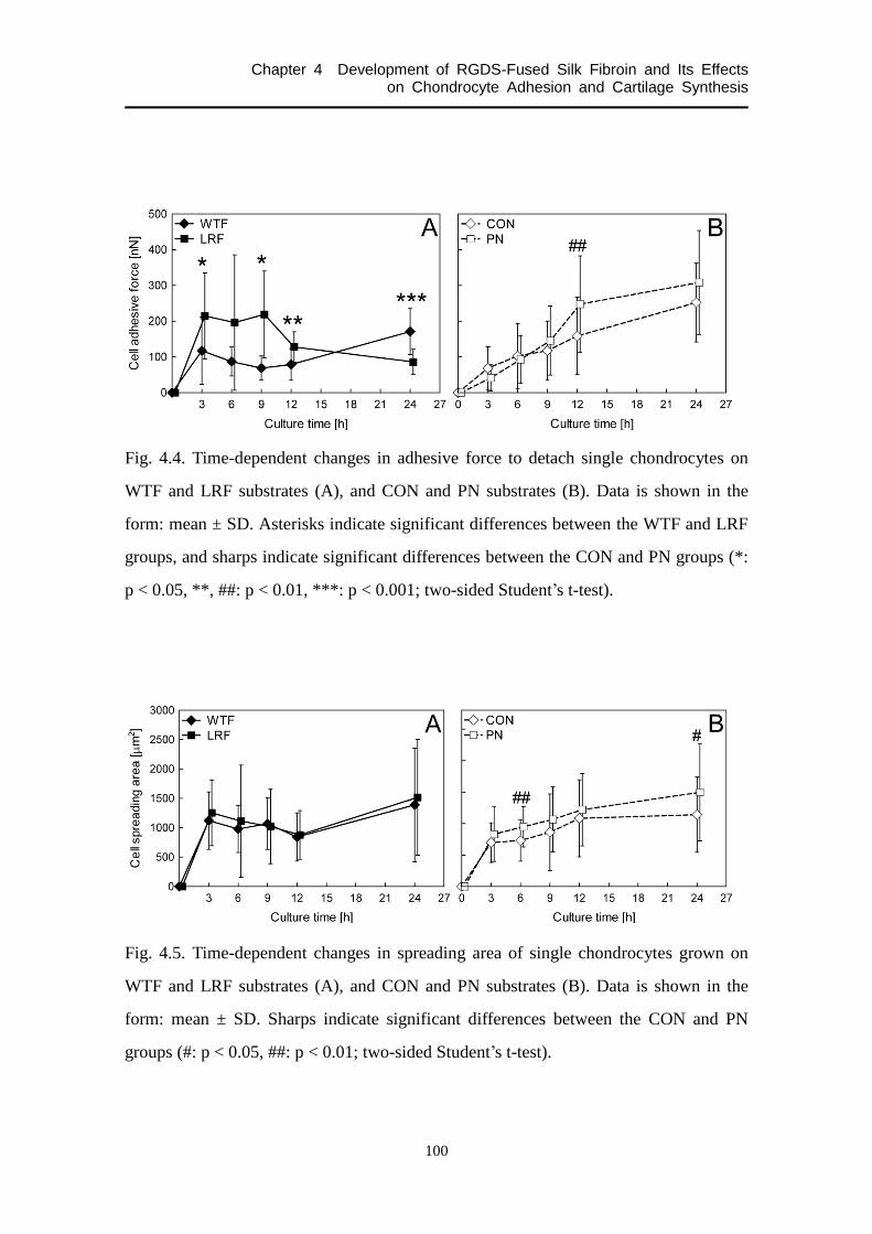
Chapter 4 Development of RGDS-Fused Silk Fibroin and Its Effects on Chondrocyte Adhesion and Cartilage Synthesis
100
Fig. 4.4. Time-dependent changes in adhesive force to detach single chondrocytes on
WTF and LRF substrates (A), and CON and PN substrates (B). Data is shown in the
form: mean ± SD. Asterisks indicate significant differences between the WTF and LRF
groups, and sharps indicate significant differences between the CON and PN groups (*:
p < 0.05, **, ##: p < 0.01, ***: p < 0.001; two-sided Student’s t-test).
Fig. 4.5. Time-dependent changes in spreading area of single chondrocytes grown on
WTF and LRF substrates (A), and CON and PN substrates (B). Data is shown in the
form: mean ± SD. Sharps indicate significant differences between the CON and PN
groups (#: p < 0.05, ##: p < 0.01; two-sided Student’s t-test).

Chapter 4 Development of RGDS-Fused Silk Fibroin and Its Effects on Chondrocyte Adhesion and Cartilage Synthesis
101
4.3.6. Cell spreading area
The cell spreading area as a function of culture time is shown in Fig. 4.5. No
significant differences were found between the WTF and LRF groups; both groups
tended to show similar time-course changes in spreading area. On the other hand,
chondrocytes grown on the PN substrate tended spread to a larger area than those grown
on the CON substrate, and these effects were significant at 6 and 24 h after seeding.
Fig. 4.6. Immunofluorescence staining of F-actin and vinculin in a chondrocyte grown
on WTF, LRF, CON, and PN substrates at 6 and 12 h after seeding. Scale bar = 20 µm.

Chapter 4 Development of RGDS-Fused Silk Fibroin and Its Effects on Chondrocyte Adhesion and Cartilage Synthesis
102
4.3.7. Cell morphology
The representative photographs of F-actin and vinculin staining for each substrate at
6 and 12 h after seeding are shown in Fig. 4.6. At 6 h after seeding, immature actin
fibers and dot-like vinculin were sporadically present in chondrocytes grown on both
the WTF and LRF substrates. At 12 h, this cell morphology was not observed but
polymerized actin fibers were formed, and dash-like vinculin was observed at the cell
processes in the LRF group. Finally, at 24 h after seeding, the latter F-actin structure and
vinculin distributions were observed in both the WTF and LRF groups (data not shown).
As described above, time-dependent morphological changes were shown in
chondrocytes cultured on the two fibroin substrates. In contrast, polymerized actin
fibers and dash-like vinculin were constantly observed in the CON and PN groups.
4.3.8. mRNA expression levels
Figure 4.7 shows the changes in the mRNA expression levels of integrins 5 and 1,
aggrecan, and collagen type II at 6, 12, and 24 h after seeding, and the data were
normalized with respect to the expression level at 0 h after seeding. The aggrecan
expression in the WTF and LRF groups showed a peak within 24 h after seeding,
whereas the aggrecan expression in the CON and PN groups only changed slightly with
time. The LRF group exhibited higher expression of aggrecan and integrins 5 and 1
at 12 h, whereas there were no significant differences in the mRNA expression levels
between the CON and PN groups.
4.3.9. SEM observation of fibroin sponges and initial cell number
Figure 4.8A shows the representative scanning electron micrographs for the WTF and
LRF sponges. Both sponges appeared to be similar in their morphology, possessing
similar pore size, pore structure, and pore size distribution.
The time-course changes in the number of chondrocytes in/on the WTF and LRF

Chapter 4 Development of RGDS-Fused Silk Fibroin and Its Effects on Chondrocyte Adhesion and Cartilage Synthesis
103
Fig. 4.7. Time-course changes in relative mRNA expression levels of integrins 5 and
1, aggrecan, and collagen type II in chondrocytes grown on WTF, LRF, CON, and PN
substrates. The data were normalized to the expression level at 0 h after seeding. Data is
shown in the form: mean ± SD. Asterisks indicate significant differences between the
WTF and LRF groups (*: p < 0.05; two-sided Student’s by t-test).
sponges are shown in Fig. 4.8B. Both groups exhibited time-dependent increase in the
cell number. At 9 h after seeding, the LRF group showed significantly higher cell
number than the WTF group. As 5.0 × 10⁵ cells were seeded onto each scaffold,
chondrocytes in/on the LRF sponge could proliferate within 9 h after seeding. However,
there were no significant differences between the groups at 24 h although the LRF
group showed a slightly larger number of cells.

Chapter 4 Development of RGDS-Fused Silk Fibroin and Its Effects on Chondrocyte Adhesion and Cartilage Synthesis
104
Fig. 4.8. Scanning electron micrographs of WTF and LRF sponges (A). Scale bar = 500
and 200 µm for 100- and 250-fold magnifications, respectively. The number of
chondrocytes in/on WTF and LRF sponges at 9 and 24 h after seeding (B). Data is
shown in the form: mean ± SD. Asterisks indicate significant differences between the
groups (**: p < 0.01; two-sided Student’s by t-test).
4.3.10. Histology findings
Histological observation of the regenerated cartilage synthesized on the WTF and
LRF scaffolds are shown in Fig. 4.9. More cartilage-like tissues were formed in the LRF
group than in the WTF group after 3 days in culture. Furthermore, after culturing for 7
days, two- to three-fold thicker tissues were formed at the surface of the LRF scaffold
compared to the WTF scaffold. The expression of collagen type I was not detected in
both groups.
4.4. Discussion
The transgenic silkworms named NK14 were able to transcript the transgene,
translate its product, and secrete the LRF, which was confirmed by Western blotting

Chapter 4 Development of RGDS-Fused Silk Fibroin and Its Effects on Chondrocyte Adhesion and Cartilage Synthesis
105
Fig. 4.9. Photographs of regenerated cartilage tissues using WTF and LRF sponges at 3
and 7 days in culture. The tissues were stained for safranin-O and immunostained for
collagen type I and II. Scale bar = 200 µm.
with anti-(RGDS)2 antibodies as shown in Fig. 4.1. Then, we evaluated the LRF as a
scaffold for chondrocytes.
It is generally thought that introduction of RGD peptides into a substrate facilitates
integrin-mediated cell attachment. In the present study, this explanation was confirmed
by the fact that the PN and LRF substrates had a higher cell-adhesive activity than the
CON and WTF substrates, respectively, as shown in Fig. 4.2C. Besides, as the
attachment of chondrocytes to fibroin substrates increased with the dose of LRF
molecules, (RGDS)2 amino acids fused with the fibroin L-chain certainly affect cell
adhesion. However, it is widely accepted that in addition to integrin-mediated biologic
adhesion, surface properties of a material (e.g., wettability and charge) greatly affect
cell–substrate adhesion [30-35]. In the present study, there were no significant

Chapter 4 Development of RGDS-Fused Silk Fibroin and Its Effects on Chondrocyte Adhesion and Cartilage Synthesis
106
differences in contact angle or potential between the WTF and LRF substrates or
between the CON and PN substrates. Additionally, no marked differences were
observable on the surfaces of the WTF and LRF films in SEM analysis as shown in Fig.
4.2A. These results suggest that the physicochemical properties of the substrates have
little effect on levels of chondrocyte adhesion.
Integrins appear to be the major cell surface receptors by which a cell can adhere
mechanically to ECMs, and chondrocytes have been shown to express several members
of the integrin family [36]. As shown in Fig. 4.2D, competitive inhibition of
chondrocyte attachment to an LRF substrate with soluble GRGDSP peptides indicated
that integrin receptors on a suspending chondrocyte were blocked by the peptides and
could not bind to ligands on the surface of a substrate. These results suggest that
differences in cell-adhesive activity between the WTF and LRF substrates were caused
by RGDS sequences in the LRF proteins, which did not exist on the WTF substrate.
Therefore, RGDS in the L-chain works on cell adhesion, suggesting that biologic
interactions between cell and material rather than physicochemical ones were
predominant in the present experiments. Thus, the relationship between chondrogenesis
and chondrocyte–material adhesion induced by RGDS sequences in the fibroin L-chain
is discussed below.
Generally, by using fibronectin- and RGD-induced substrates, chondrcoyte–material
adhesion is enhanced, which leads phenotypic and mechanical changes of chondrocytes:
the cells tend to lose their chondrogenic phenotype [5,6,17] and the mechanical
properties of the cells such as adhesive force are strengthened [37]. The latter effect was
seen with both RGDS expressed in the fibroin L-chain and ProNectin® F coated on a
glass substrate as shown in Fig. 4.4, although there was no dose-dependent effects on
cell adhesive force from 0 to 1.5 mol% LRF. The mRNA expression of aggrecan, which
encodes cartilage-specific proteoglycan, peaked at a similar level in the WTF and LRF
groups, although its expression was delayed in the latter. In addition, chondrocytes
grown on LRF sponges could synthesize thicker cartilage tissues than those cultured on
WTF sponges during the early culture period. These results shown in Figs. 4.7 and 4.9

Chapter 4 Development of RGDS-Fused Silk Fibroin and Its Effects on Chondrocyte Adhesion and Cartilage Synthesis
107
suggest that RGDS amino acids fused with the L-chain can facilitate cell adhesive
strength, without down-regulating the chondrocyte-specific phenotype.
Chondrocytes grown on the WTF and LRF substrates exhibited a maximum adhesive
force within 12 h after seeding, but both the CON and PN groups showed only a
monotonic increase. Others have also shown monotonous enhancement of adhesive
force in cells cultured on glass, fibronectin, or a culture dish, although the detaching
process and direction of force measurement were different [37-39]. These results could
indicate that the specific time-dependent changes in adhesive force of the WTF and
LRF groups were predominantly affected by the characteristic of fibroin, and that the
RGDS sequences in the L-chain had an influence on the expression period and the peak
value. However, the RGDS in the L-chain appeared to have no effect on cell spreading,
unlike the enhancement effect of PN coated on a glass substrate and RGD peptides fixed
on a substrate as seen in both the present and previous studies [1,2].
Considering that proteoglycan has been reported to inhibit and regulate
integrin-mediated cell–material adhesion [40,41], the specific gene expression of
integrins 5 and 1, which recognize an RGD sequence in ECMs [14-16,36], and
aggrecan in the LRF group could be related to the adhesive force. Furthermore, higher
gene expression of integrins in the LRF group might affect the earlier changes in actin
polymerizations and distributions of focal adhesion points. This is supported by reports
that integrins bind to the cytoskeleton (to a polymerized actin called F-actin), mediated
by anchor molecules such as vinculin, talin, and -actinin, and clusters to construct
focal adhesions [42-44]. Although the development of F-actin and the expression of
focal adhesion points are important factors for adhesive force [12,37-39], there appears
to be no relations between them in chondrocytes grown on the two fibroin substrates.
The results of the present study suggest that RGDS amino acids fused with the
L-chain protein of the silk fibroin facilitate cartilage tissue formation as shown in Fig.
4.9 but, in contrast to PN, do not induce spreading and dedifferentiation of chondrocytes.
Hsu et al. [5] suspected that the effect of RGD could be substrate (scaffold)-dependent,
showing that an RGD-containing protein introduced into chitosan-alginate-hyaluronate

Chapter 4 Development of RGDS-Fused Silk Fibroin and Its Effects on Chondrocyte Adhesion and Cartilage Synthesis
108
composite or PLLA-poly(D,L-lactide-coglycolide) blended scaffolds demonstrated
different effects on chondrogenesis [5,45]. Jung et al. [8] suggested that an optimal
concentration of RGD might vary in different cell or substrate types and help to form
cartilaginous tissues, but very strong adhesion is likely to suppress matrix production.
The results of adhesion of single chondrocytes grown on an LRF substrate (Figs.
4.4–4.6) suggest that adhesion between a chondrocyte and an LRF substrate was not
excessively strong as well as chondrocyte adhesion to PN; instead, moderate adhesion
was sufficient to maintain the chondrogenic phenotype. In particular, the specific
enhancement effect on the peak strength of adhesive force might influence the
organization of cartilage tissues because a peak was not observed in the force of
chondrocytes cultured on glass or PN substrates, on which chondrocytes cannot
synthesize hyaline-like cartilage tissues [13,17]. Although it is difficult to explain
precisely the mechanisms involved in the specific behavior of initial adhesion and
chondrogenesis from the results of the present study, we infer that changes in adhesive
force are crucial via the deformation of cell membranes, the distribution pattern of focal
contacts, and the effect of substances synthesized by chondrocytes, as described
previously by Yamamoto et al. [12]. These adhesion structures can affect the signal
cascade of phenotypic expression and/or production of ECMs [46,47]. Hence,
considering that there were not remarkable differences in the initial number of
chondrocytes on/in WTF or LRF scaffolds at 24 h after seeding as shown in Fig. 4.8B,
early integrin-mediated signal changes induced by the adhesion to LRF within 24 h (i.e.,
the increase and/or delay of integrin mRNA expressions as shown in Fig. 4.7) might
stimulate cartilage tissue formation. Another possibility for the facilitation of
chondrogenesis is that the adhesive force of chondrocytes affected their migration and
aggregation. This suggestion is supported by the findings that cell adhesive strength is
related to cell motility [48,49] and that chondrocyte movement and distribution in a
fibroin sponge play a central role in the production of cartilage-specific matrices [50].
A fibroin H-chain protein is reported to be composed of a crystalline region linked
with an amorphous region [51], whereas it is assumed that there are no crystal structures

Chapter 4 Development of RGDS-Fused Silk Fibroin and Its Effects on Chondrocyte Adhesion and Cartilage Synthesis
109
in an L-chain [52,53] (where the RGDS sequences are fused in the present study). On
the other hand, ProNectin® F is reported to be composed of the crystallized sequence
containing (Gly-Ala-Gly-Ala-Gly-Ser)9 ((GAGAGS)9) from fibroin H-chain, which
forms a -sheet structure where a 10 amino acid sequence from fibronectin containing
RGDS is presented in turn [54,55]. Additionally, cell-adhesive activity of an RGD
sequence can be affected by its conformation [56,57]. Therefore, the specific effects of
RGDS in the fibroin L-chain might be ascribable to the activity of the amino acids and
the conformational effects of the sequences. However, further studies are necessary to
confirm these discussions and to clarify the mechanisms.
4.5. Conclusions
The results of the present study have demonstrated that chondrocytes grown on the
L-RGDSx2 fibroin substrate show similar spreading area but higher mRNA expression
levels of integrins 5 and 1 at 12 h after seeding compared to the cells on the
wild-type fibroin substrate. Further, the specific enhancement of the peak adhesive force
has been exhibited within 12 h. These changes were not shown between chondrocytes
culture on glass and ProNectin® F substrates. The study also suggests that the sequence
in the L-chain can facilitate the synthesis of cartilage tissue.

Chapter 4 Development of RGDS-Fused Silk Fibroin and Its Effects on Chondrocyte Adhesion and Cartilage Synthesis
110
References
[1] Ohno S, Noshiro M, Makihira S, Kawamoto T, Shen M, Yan, W, et al. RGD-CAP
(ig-h3) enhances the spreading of chondrocytes and fibroblasts via integrin 11.
Biochim Biophys Acta 1999;1451:196-205.
[2] Jeschke B, Meyer J, Jonczyk A, Kessler H, Adamietz P, Meenen NM, et al.
RGD-peptides for tissue engineering of articular cartilage. Biomaterials
2002;23:3455-63.
[3] Genes NG, Rowley JA, Mooney DJ, Bonassar LJ. Effect of substrate mechanics on
chondrocyte adhesion to modified alginate surfaces. Arch Biochem Biophys
2004;422:161-7.
[4] Meinel L, Hofmann S, Karageorgiou V, Zichner L, Langer R, Kaplan D, et al.
Engineering cartilage-like tissue using human mesenchymal stem cells and silk
protein scaffolds. Biotechnol Bioeng 2004;88:379-91.
[5] Hsu SH, Chang SH, Yen HJ, Whu SW, Tsai CL, Chen DC. Evaluation of
biodegradable polyesters modified by type II collagen and Arg-Gly-Asp as tissue
engineering scaffolding materials for cartilage regeneration. Artif Organs
2006;30:42-55.
[6] Connelly JT, Garcia AJ, Levenston ME. Inhibition of in vitro chondrogenesis in
RGD-modified three-dimensional alginate gels. Biomaterials 2007;28:1071-83.
[7] Tigli RS, Gumusderelioglu M. Evaluation of RGD- or EGF-immobilized chitosan
scaffolds for chondrogenic activity. Int J Biol Macromol 2008;43:121-8.
[8] Jung HJ, Park K, Kim JJ, Lee JH, Han KO, Han DK. Effect of RGD-immobilized
dual-pore poly(L-lactic acid) scaffolds on chondrocyte proliferation and
extracellular matrix production. Artif Organs 2008;32:981-9.
[9] Meinel AJ, Kubow KE, Klotzsch E, Garcia-Fuentes M, Smith ML, Vogel V, et al.
Optimization strategies for electrospun silk fibroin tissue engineering scaffolds.
Biomaterials 2009;30:3058-67.
[10] Aoki H, Tomita N, Morita Y, Hattori K, Harada Y, Sonobe M, et al. Culture of

Chapter 4 Development of RGDS-Fused Silk Fibroin and Its Effects on Chondrocyte Adhesion and Cartilage Synthesis
111
chondrocytes in fibroin-hydrogel sponge. Biomed Mater Eng 2003;13:309-16.
[11] Chueh S, Tomita N, Yamamoto K, Harada Y, Nakajima M, Terao T, et al.
Transplantation of allogeneic chondrocytes cultured in fibroin sponge and stirring
chamber to promote cartilage regeneration. Tissue Eng 2007;13:483-92.
[12] Yamamoto K, Tomita N, Fukuda Y, Suzuki S, Igarashi N, Suguro T, et al.
Time-dependent changes in adhesive force between chondrocytes and silk fibroin
substrate. Biomaterials 2007;28:1838-46.
[13] Park GE, Pattison MA, Park K, Webster TJ. Accelerated chondrocyte function on
NaOH-treated PLGA scaffolds. Biomaterials 2005;26:3075-82.
[14] Rouslahti E, Pierschbacher MD. Arg-Gly-Asp: a versatile cell recognition signal.
Cell 1986;44:517-8.
[15] Rouslahti E, Pierschbacher MD. New perspectives in cell adhesion: RGD and
integrins. Science 1987;23:491-7.
[16] Hynes RO. Integrins: versatility, modulation, and signaling in cell adhesion. Cell
1992;69:11-25.
[17] Brodkin KR, Garcia AJ, Levenston ME. Chondrocyte phenotypes on different
extracellular matrix monolayers. Biomaterials 2004;25:5929-38.
[18] Tanaka K, Kajiyama N, Ishikura K, Waga S, Kikuchi A, Ohtomo K, et al.
Determination of the site of disulfide linkage between heavy and light chains of silk
fibroin produced by Bombyx mori. Biochim Biophys Acta 1999;1432:92-103.
[19] Kojima K, Kuwana Y, Sezutsu H, Kobayashi I, Uchino K, Tamura T, et al. A new
method for the modification of fibroin heavy chain protein in the transgenic
silkworm. Biosci Biotechnol Biochem 2007;71:2943-51.
[20] Tomita M, Munetsuna H, Sato T, Adachi T, Hino R, Hayashi M, et al. Transgenic
silkworms produced recombinant human type III procollagen in cocoons. Nat
Biotechnol 2003;21:52-6.
[21] Inoue S, Kanda T, Imamura M, Quan GX, Kojima K, Tanaka H, et al. A fibroin
secretion-deficient silkworm mutant, Nd-sD, provides an efficient system for
producing recombinant proteins. Insect Biochem Mol Biol 2005;35:51-9.

Chapter 4 Development of RGDS-Fused Silk Fibroin and Its Effects on Chondrocyte Adhesion and Cartilage Synthesis
112
[22] Adachi T, Tomita M, Shimizu K, Ogawa S, Yoshizato K. Generation of hybrid
transgenic silkworms that express Bombyx mori prolyl-hydroxylase -subunits and
human collagens in posterior silk glands: production of cocoons that contained
collagens with hydroxylated proline residues. J Biotechnol 2006;126:205-19.
[23] Yanagisawa S, Zhu Z, Kobayashi I, Uchino K, Tamada Y, Tamura T, et al.
Improving cell-adhesive properties of recombinant Bombyx mori silk by
incorporation of collagen of fibronectin derived peptides produced by transgenic
silkworms. Biomacromolecules 2007;8:3487-92.
[24] Tamura T, Thibert C, Royer C, Kanda T, Abraham E, Kamba M, et al. Germline
transformation of the silkworm Bombyx mori L. using a piggyBac
transposon-derived vector. Nat Biotechnol 2000;18:81-4.
[25] Tamada Y. New process to form a silk fibroin porous 3-D structure.
Biomacromolecules 2005;5:217-28.
[26] Majima T, Marchuk LL, Shrive NG, Frank CB, Hart DA. In-vitro cyclic loading of
an immobilized and mobilized ligament autograft selectively inhibits mRNA levels
for collagenase (MMP-1). J Orthop Sci 2000;5:503-10.
[27] Ohashi H, Maeda T, Mishima H, Otori T, Nishida T, Sekiguchi K. Up-regulation of
integrin 51 expression by interleukin-6 in rabbit corneal epithelial cells. Exp Cell
Res 1995;218:418-23.
[28] Huang CY, Hangar KL, Frost LE, Sun Y, Cheung HS. Effects of cyclic compressive
loading on chondrogenesis of rabbit bone-marrow derived mesenchymal stem cells.
Stem Cells 2004;22:313-23.
[29] Tamada Y, Kulik EA, Ikeda Y. Simple method for platelet counting. Biomaterials
1995;16: 259-61.
[30] Van Wachem PB, Hogt AH, Beugeling T, Feijen J, Bantjes A, Detmers JP, et al.
Adhesion of cultured human endothelial cells onto methacrylate polymers with
varying surface wettability and charge. Biomaterials 1987;8:323-8.
[31] Kishida A, Iwata H, Tamada Y, Ikada Y. Cell behaviour on polymer surfaces
grafted with non-ionic and ionic monomers. Biomaterials 1991;12:786-92.

Chapter 4 Development of RGDS-Fused Silk Fibroin and Its Effects on Chondrocyte Adhesion and Cartilage Synthesis
113
[32] Tamada Y, Ikada Y. Cell adhesion to plasma-treated polymer surfaces. Polymer
1993;34:2208-12.
[33] Lee JH, Lee JW, Khang G, Lee HB. Interaction of cells on chargeable functional
group gradient surfaces. Biomaterials 1997;18:351-8.
[34] Arima Y, Iwata H. Effect of wettability and surface functional groups on protein
adsorption and cell adhesion using well-defined mixed self-assembled monolayers.
Biomaterials 2007;28:3074-82.
[35] Arima Y, Iwata H. Effects of surface functional groups on protein adsorption and
subsequent cell adhesion using self-assembled monolayers. J Mater Chem
2007;17:4079-87.
[36] Loeser RF. Chondrocyte integrin expression and function. Biorheology
2000;37:109-16.
[37] Athanasiou KA, Thoma BS, Lanctot DR, Shin D, Agrawal CM, LeBaron RG.
Development of the cytodetachment technique to quantify mechanical adhesiveness
of the single cell. Biomaterials 1999;20:2405-15.
[38] Hoben G, Huang W, Thoma BS, LeBaron RG, Athanasiou KA. Quantification of
varying adhesion levels in chondrocytes using the cytodetacher. Ann Biomed Eng
2002;30:703-12.
[39] Huang W, Anvari B, Torres JH, LeBaron RG, Athanasiou KA. Temporal effects of
cell adhesion on mechanical characteristics of the single chondrocyte. J Orthop Res
2003;21:88-95.
[40] Yamagata M, Suzuki S, Akiyama SK, Yamada KM, Kimata K. Regulation of
cell-substrate adhesion by proteoglycans immobilized on extracellular substrates. J
Biol Chem 1989;264:8012-8.
[41] Imoto E, Kakuta S, Hori M, Yagami K, Nagumo M. Adhesion of a chondrocytic
cell line (USAC) to fibronectin and its regulation by proteoglycan. J Oral Pathol
Med 2002;31:35-44.
[42] Greenwood JA, Murphy-Ullrich JE. Signaling of de-adhesion in cellular regulation
and motility. Microsc Res Tech 1998;43:420-32.

Chapter 4 Development of RGDS-Fused Silk Fibroin and Its Effects on Chondrocyte Adhesion and Cartilage Synthesis
114
[43] Giancotti FG, Ruoslahti E. Integrin signaling. Science 1999;285:1028-32.
[44] Martin KH, Slack JK, Boerner SA, Martin CC, Parsons JT. Integrin connections
map: to infinity and beyond. Science 2002;296:1652-3.
[45] Hsu S, Whu SW, Hsieh S, Tsai C, Chen DC, Tan T. Evaluation of
chitosan-alginate-hyaluronate complexes modified by an RGD-containing protein
as tissue engineering scaffolds for cartilage regeneration. Artif Organs
2004;28:693-703.
[46] Enomoto M, Leboy PS, Menko AS, Boettiger D. 1 integrins mediate chondrocyte
interaction with type I collagen, type II collagen, and fibronectin. Exp Cell Res
1993;205:276-85.
[47] Takagi M, Kitabayashi T, Koizumi S, Hirose H, Kondo S, Fujikawa M, et al.
Correlation between cell morphology and aggrecan gene expression level during
differentiation from mesenchymal stem cell to chondroytes. Biotechnol Lett
2008;30:1189-95.
[48] DiMilla PA, Barbee K, Lauffenburger DA. Mathematical model for the effects of
adhesion and mechanics on cell migration speed. Biophys J 1991;60:15-37.
[49] DiMilla PA, Stone JA, Quinn JA, Albelda SM, Lauffenburger DA. Maximal
migration of human smooth muscle cells on fibronectin and type IV collagen occurs
at an intermediate attachment strength. J Cell Biol 1993;122:729-37.
[50] Kawakami M, Tomita N, Shimada Y, Yamamoto K, Tamada Y, Kachi ND, et al.
Chondrocyte distribution and cartilage regeneration in silk fibroin sponge. Biomed
Mater Eng 2011;21:53-61.
[51] Mita K, Ichimura S, James TC. Highly repetitive structure and its organization of
the silk fibroin gene. J Mol Evol 1994;38:583-92.
[52] Tanaka K, Kajiyama N, Ishimura K, Waga S, Kikuchi A, Ohtomo K, et al.
Determination of the site of disulfide linkage between heavy and light chains of silk
fibroin produced by Bombyx mori. Biochim Biophys Acta 1999;1432:92-103.
[53] Yamaguchi K, Kikuchi Y, Takagi T, Kikuchi A, Oyama F, Shimura K, et al. Primary
structure of the silk fibroin light chain determined by cDNA sequencing and peptide

Chapter 4 Development of RGDS-Fused Silk Fibroin and Its Effects on Chondrocyte Adhesion and Cartilage Synthesis
115
analysis. J Mol Biol 1989;210:127-39.
[54] Cappello J, Crissman JW. The design and production of bioactive protein polymers
for biomedical applications. Polymer Prepr 1990;31:193-4.
[55] Anderson JP, Cappello J, Martin DC. Morphology and primary crystal structure of a
silk-like protein polymer synthesized by genetically engineered E. Coli bacteria.
Biopolymers 1994;34:1049-57.
[56] Maeda T, Oyama R, Ichihara-Tanaka K, Kimizuka F, Kato I, Titani K, et al. A novel
cell adhesive protein engineered by insertion of the Arg-Gly-Asp-Ser tetrapeptide. J
Biol Chem 1989;264:15165-8.
[57] Hersel U, Dahmen C, Kessler H. RGD modified polymers: biomaterials for
stimulated cell adhesion and beyond. Biomaterials 2003;24:4385-415.

Chapter 4 Development of bFGF-Fused Silk Fibroin, Evaluation of Its Activity, and Application as a Scaffold for Cartilage Regeneration
116

Chapter 5 Summary and Conclusions
117
Chapter 5
Summary and Conclusions
5.1. Summary
Chapter 2
A large number of cellular scaffolds modified to have functional substitutes have
been developed by using chemical modification or post-conjugation techniques, but the
processes are elaborate and costly. Here, we have developed basic fibroblast growth
factor (bFGF)-fused fibroin by the use of transgenic silkworm technology, aiming at
creating a scaffold with cell-growth function. Our molecular design has enabled the
bFGF to be released from the fibroin molecule by collagenase. However, a process to
fabricate a spongy scaffold of the bFGF-fused fibroin inactivated cell-proliferative
effects of the growth factor. Thus the solution and sponge of the bFGF-fused fibroin
were subjected to a refolding treatment with the glutathione redox system to restore its
biological activity. The bFGF-fused fibroin degummed in a boiling 0.02 M Na2CO3 and
dissolved in 9.0 M LiBr reactivated by the refolding process, showing
growth-promoting effects on NIH3T3 fibroblasts. Meanwhile, the bFGF in the fibroin
sponge refolded after autoclaving showed slight effects on the proliferation of NIH3T3
cells and on the matrix production of chondrocytes. Further studies are required for a
practical use of the genetically-modified fibroin fused with a bioactive macromolecule.
Chapter 3
Cellular mechanical properties are implicated in numerous cell behaviors, but their

Chapter 5 Summary and Conclusions
118
involvement in cell differentiation process has remained unclear. Since mechanical
interactions between chondrogenic cells and their surrounding environment heavily
affect the maintenance of their differentiation phenotype, here, using a chondrogenic
cell strain ATDC5, we evaluated cell mechanical properties (e.g., adhesive force and
stiffness) and gene expression levels in differentiation culture. The adhesive force
appeared to be affected by both cellular cytoskeletal and adhesive constructions.
Treatment with Y27632, which accordingly inhibits actin polymerization, decreased the
adhesive force while increased chondrogenic gene expressions, suggesting the both of
them are interrelated via the mediation of actin cytoskeleton. However, the mechanical
property did not represent chondrogenic differentiative stages as obviously as the
biochemical characteristics did. Meanwhile, interestingly, changes in cell distribution
maps of the force in the differentiation process indicated that the cells have different
levels of mechanical properties in the undifferentiated state, whereas they tend to
converge when the differentiative stage is in a lull. These results reaffirm the cellular
diversity during differentiation from a mechanical perspective and provide important
information to the fields of generation and scaffold-based tissue regeneration, where
cell–substrate adhesion plays a role.
Chapter 4
Initial chondrocyte–silk fibroin interactions are implicated in chondrogenesis when
using fibroin as a scaffold for chondrocytes. Here, we focused on integrin-mediated
cell–scaffold adhesion and prepared cell adhesive fibroin in which a tandem repeat of
the Arg-Gly-Asp-Ser (RGDS) sequence was genetically interfused in the fibroin light
chain (L-chain) (L-RGDSx2 fibroin). We investigated the effects of the sequence on
chondrocyte adhesion and cartilage synthesis, in comparison to the effects of
ProNectin® F. As the physicochemical surface properties (e.g., wettability and
potential) of the fibroin substrate were not affected by the modification, specific cell
adhesion to the RGDS predominately changed the chondrocyte adhesive state. This was
also supported by the competitive inhibition of chondrocyte attachment to the

Chapter 5 Summary and Conclusions
119
L-RGDSx2 fibroin substrate with soluble RGD peptides in the medium. Unlike
ProNectin® F, the expression of RGDS in the fibroin L-chain had no effect on
chondrocyte spreading area but enhanced mRNA expression levels of integrins 5 and
1, and aggrecan at 12 h after seeding. Although both the sequence and ProNectin® F
increased cell adhesive force, chondrocytes grown on the fibroin substrate exhibited a
peak in the force with time in culture. These results suggested that moderate
chondrocyte adhesion to fibroin induced by the RGDS sequence was able to maintain
the chondrogenic phenotype and, from the histology findings, the sequence could
facilitate chondrogenesis.
5.2. Conclusions
This study aimed at the development of useful, practical scaffolds which enable
effective cartilage regeneration, where transgenic silkworm technology was used to
design silk fibroin molecules for the sake of appending new functions to fibroin scaffold.
Three purposes were targeted to accomplish the final goal of this study: to append
promoting effects on cell proliferation to silk fibroin scaffold; to seek the index of
scaffold designing alternative to bioactive macromolecules; and to add stimulatory
effects on chondrogenesis by modulating the cell-adhesive function of silk fibroin
scaffold. Conclusions to the three purposes are described as follows:
1) bFGF was genetically fused with the fibroin L-chain molecule, which intended to
make silk fibroin scaffold have enhancement effects on cell proliferation. Although
recombinant silk fibroin ‘molecule’ which stimulates cell proliferation was
developed successfully, we have not yet accomplished to create fibroin ‘scaffold’
with such function. This is because the bFGF fused with the L-chain was
inactivated in the process to form the 3-D porous structure of fibroin. Bioactive
macromolecules fused with fibroin molecule were shown to be difficult to function

Chapter 5 Summary and Conclusions
120
after fabricated into scaffold.
2) Measurement of cell adhesive force at several phases of chondrogenic
differentiation showed a possibility that mechanical cell–material interactions
reflect chondrogenic phenotype. This finding suggests that changes in the
cell-adhesive function of silk fibroin which affect cell mechanical properties can
result in the efficiency of chondrogenesis in/on fibroin scaffold.
3) RGDS peptides genetically fused with the fibroin L-chain affected chondrocyte
adhesion, including the adhesive force, and facilitated chondrogenesis in/on fibroin
spongy scaffold. The RGDS strengthened the adhesive force of chondrocytes as
shown in the effect of ProNectin® F, however, chondrocytes grown on the
RGDS-fused fibroin substrate maintained the specific behavior of the adhesive
force stemmed from the cell–fibroin interaction. These findings suggest the RGDS
and the fibroin act synergistically on chondrocytes, which can be induced by the
fact that the RGDS peptides were designed to be fused with the L-chain.
Transgenic silkworm technology makes it possible to create chimeric silk fibroin
molecule in accordance with our design: we can design which peptides or proteins to be
introduced and where they are fused. For the sole purpose of creating silk fibroin
protein fused with biologically-active macromolecule, all we have to do is to design the
modified fibroin molecule, construct the vector, and generate the silkworm strain. Then
the silkworms produce the modified fibroin proteins in their posterior silkglands, and
the proteins relatively well-maintain the activity of the macromolecule as shown in the
case of bFGF-fused fibroin. However, in order to develop silk fibroin scaffold with the
function stemmed from the recombinant macromolecule, it is essential to design the
whole process, including the fabrication, preservation, and usage of the scaffold. In
contrast, it is clarified that silk fibroin fused with recombinant peptide composed of
several amino-acid residues stably shows functions induced by the recombinant peptide
even after fabricated into scaffold. The results of this study has also suggested the effect
of recombinant peptides or proteins on chondrocytes is dependent on their location in

Chapter 5 Summary and Conclusions
121
the fibroin molecule, which means the function of recombinant molecules is not simply
added to but can be exerted synergistically with the function of silk fibroin. We infer
that a peptide or protein fused with the H-chain is immobilized more rigidly that fused
with the L-chain. To design and develop functional scaffolds for tissue engineering, it is
necessary to feedback the results in evaluation of tissue regeneration in vitro and in vivo
to the design of scaffold at the molecular level, but there are lots of indexes to be
reflected to the designing and their integration is complicating. Cell mechanical
properties induced by the adhesion to the scaffold can represent the information on cell
differentiation and scaffold materials. Therefore, the mechanical evaluation of cells
grown in/on scaffold can simplify the scaffold designing to achieve its practical
application.
5.3. Perspectives
Tissue engineering is an interdisciplinary field that applies the principles and methods
of engineering and the life science toward the development of biological substitutes that
restore, maintain, or improve tissue function, and to achieve the ultimate goal of
functional neoorganogenesis for human use, the close, interdisciplinary collaboration of
surgeons, engineers, chemists, and biologists is required. However, there are few
opportunities for such collaboration and interdisciplinary educational systems have not
been established especially in Japan. To accomplish this study, I have used a variety of
techniques including the development of scaffold materials using transgenic techniques
and evaluations with biochemical and biomechanical methods. The results of this study
are multidisciplinary findings and can be important for the clinical application of
scaffold materials for tissue engineering. Particularly, biomechanical viewpoints,
evaluations, and analysis are essential to clarify the mechanisms for the regeneration of
3-D structures and functions of living tissues in a scaffold. They are also important to
achieve bioenvironmental designing for effective tissue regeneration. In the current

Chapter 5 Summary and Conclusions
122
situation, however, biomechanical studies including this study lack validity in biological
phenomena in vivo, which is caused by the limitation of the techniques in the
biomechanical field. In order to resolve this issue and to make biomechanical studies
useful for the practical use of tissue engineering, new technologies need to be created by
fusing multidisciplinary methods. Fortunately, I had opportunities to discuss and study
with researchers from various academic fields, including clinical medicine, biomaterial,
molecular biology, and microengineering. Using these interdisciplinary connections and
experimental techniques, I would like to create new biotechnologies and biomaterials
that can help promote the clinical application of regenerative medicine from
biomechanical viewpoints. I am sure to keep problem-oriented studying by fusing
multidiscipline.
5.4. Research achievements
5.4.1. Original Research Papers
Chapter 2
1. Kambe Y, Kojima K, Tomita N, and Tamada Y. Development of bFGF-fused silk
fibroin, evaluation of its activity, and application as a scaffold for cartilage
regeneration. Biomaterials, in preparation.
Chapter 3
2. Kambe Y, Hayashi N, and Tomita N. Adhesive force behavior of single ATDC5
cells in chondrogenic culture. Biochemical and Biophysical Research
Communications 2012; 420: 241-6.
Chapter 4
3. Kambe Y, Yamamoto K, Kojima K, Tamada Y, and Tomita N. Adhesion of a single

Chapter 5 Summary and Conclusions
123
chondrocyte on RGDS-transgenic fibroin substrate and tissue formation (in
Japanese). Japanese Journal of Clinical Biomechanics 2009; 30: 71-6.
4. Kambe Y, Takeda Y, Yamamoto K, Kojima K, Tamada Y, and Tomita N. Effect of
RGDS-expressing-fibroin dose on initial adhesive force of a single chondrocyte.
Bio-Medical Materials and Engineering 2010; 20: 309-16.
5. Kambe Y, Yamamoto K, Kojima K, Tamada Y, and Tomita N. Effects of RGDS
sequence genetically interfused in the silk fibroin light chain protein on
chondrocyte adhesion and cartilage synthesis. Biomaterials 2010; 31: 7503-11.
5.4.2. Presentation at international conferences
1. Kambe Y, Yamamoto K, Kojima K, Tamada Y, and Tomita N. Adhesive force of a
single chondrocyte on RGDS-transgenic fibroin substrate, 55th Annual Meeting of
the Orthopaedic Research Society 2009; 1294: Las Vegas, USA.
2. Kambe Y, Yamamoto K, Kojima K, Tamada Y, and Tomita N. RGDS sequences
genetically induced in the fibroin light-chain protein operate positively for cartilage
tissue synthesis. 56th Annual Meeting of the Orthopaedic Research Society 2010;
1328: New Orleans, USA.
3. Kambe Y, Yamamoto K, Kojima K, Tamada Y, and Tomita N. Effects of RGDS
genetically interfused into fibroin light chain protein on chondrocytes adhesive
force. 4th World Congress on Adhesion and Related Phenomena 2010; O-17.1:
Arcachon, France.
4. Kambe Y, Kojima K, Tomita N, and Tamada Y. Development of bFGF-fused silk
and its mitogenic activity. 9th World Biomaterials Congress 2012; 2285: Chengdu,
China.

Chapter 5 Summary and Conclusions
124
The others
5. Hirakata E, Tomita N, Tamada Y, Suguro T, Nakajima M, Kambe Y, Yamada K,
Yamamoto K, Kawakami M, Shenzhi X, Otaka A, Okumura H, and Suzuki S.
Cartilage repair of patella using fibroin based cell-delivery system. 18th European
Conference on Orthopaedics 2010; P107: Davos, Switzerland.
6. Hayashi N, Kambe Y, Yamamoto K, Kojima K, Tamada Y, and Tomita N. Effect of
RGDS sequences introduced in silk fibroin substrate on the adhesive force of
chndrocyte. 6th World Congress on Biomechanics 2010; D4-D-T4.4-03: Singapore,
Singapore.
7. Takahashi K, Kambe Y, Hayashi N, Yamada Y, Yamamoto K, Kojima K, Tamada Y,
and Tomita N. Effects of low-intensity pulsed ultrasound stimulation on
chondrocytes cultured on RGD-induced fibroin substrate. International Society for
Technology in Arthoplasty, 24th Annual Congress 2011; 517: Bruges, Belgium.
5.4.3. Awards and other remarks
1. Alumnus of the Nano-Medinine Merger Education Unit at Kyoto University, 2009.
2. Best Poster Award at the report meeting of problem solution training in the
Nano-Medinine Merger Education Unit at Kyoto University, 2009.
3. Biomaterials 2010–The Year in Images, 2010.
4. Best Presentation Award at the 21st JSME Conference on Frontiers in
Bioengineering, 2011.
5. Alumnus of the Education Program for Global Leaders in Advanced Engineering

Chapter 5 Summary and Conclusions
125
and Pharmaceutical Sciences at Kyoto University, 2011.
6. Best Poster Award at the Tsukuba Biomedical Forum 2012, 2012.
7. Research Fellow of the Japan Society for the Promotion of Science (DC2), 2012
8. Young Scientist Award at the 9th World Biomaterials Congress, 2012.
9. Alumnus of the Institutional Program for Young Researcher Oversea Visits, Subject
R34 at Department of Mechanical Engineering and Science, Kyoto University,
2012.

Chapter 5 Summary and Conclusions
126

Acknowledgements
127
Acknowledgements
This doctoral dissertation would never have been possible without the guidance, the
help, and the support from several individuals who in one way or another contributed
and extended their valuable assistance in the preparation and completion of this study.
First and foremost, I would like to express my deepest gratitude to my supervisor, Dr.
Naohide Tomita, Professor of the Graduate School of Engineering, Kyoto University. In
addition to his excellent suggestions from both mechanical and medical viewpoints, his
belief to conduct problem-oriented research always inspired me. He let me experience a
lot of things, such as participation in multidiscipline conferences, temporary transfers to
a company and national institutes in Japan and overseas.
I owe my sincere gratitude to Dr. Yasushi Tamada, Leader of the Silk Materials
Research Unit, National Institute of Agrobiological Sciences. He offered me precious
opportunities to study in his research unit for two years, while he supported me with
continuous advice and encouragement from the standpoint of biomaterials. He also
provided the fibroin films and sponges used in this study.
I would like to express my special gratitude to Dr. Koji Yamamoto, Assistant
Professor of the Graduate School of Medicine, Kyoto University. I learned a lot from his
sincere attitude toward study. He always cared me even while I was in difficulties, and I
cannot appreciate him too much.
I would like to show my great thanks to Dr. Katsura Kojima, Senior Researcher of the
Silk Materials Research Unit, National Institute of Agrobiological Sciences, for his
sincere support in teaching me molecular-biological knowledge and techniques, creating
transgenic silkworms, and providing cocoons of the silkworms.

Acknowledgements
128
My special thanks go to Dr. Taiji Adachi, Professor of the Institute for Frontier
Medical Sciences, Kyoto University, and Dr. Ari Ide-Ektessabi, Professor of the
Graduate School of Engineering, Kyoto University, who reviewed this thesis and
offered valuable suggestions and insights.
I am grateful to Dr. Masaya Yamamoto, Associate Professor of the Institute for
Frontier Medical Sciences, Kyoto University, for his advice and assistance in measuring
the potential of protein-coated substrates.
I would like to express my thanks to Mr. Takahisa Matsushita and Ms. Kumiko
Kogishi for helping with histological staining of regenerated cartilage.
I am indebted to all of my colleagues in the Tomita Laboratory, including Yuji Takeda,
Nobumasa Hayashi, and Kazuya Takahashi, who helped collect experimental data;
Turner Alex, who carefully corrected my poor English; and Akihisa Otaka, who gave
me helpful suggestions.
I am also thankful to my colleagues in the Silk Materials Research Unit, including
Hiroko Saitoh, who prepared the fibroin-coated glass plates; and Hitomi Takayanagi and
Hiroko Saitoh, who bred silkworms.
I appreciate Kyoto University-Venture Business Laboratory for the use of their
experimental laboratory.
This study was supported in part by Integrated Research Project for Plant, Insect and
Animal Using Genome Technology (Ministry of Agriculture, Forestry and Fisheries of
Japan), Grant-in-Aid for Creative Scientific Research (Japan Science and Technology
Agency), and Agri-Health Translational Research Project (Ministry of Agriculture,
Forestry and Fisheries of Japan).
Finally, I would like to express my gratitude to my family: especially to my parents
for their understanding, love, and continuous support – both mentally and financially;
and to my wife for her smile and cheers.
March 2013
Yusuke KAMBE

DOCTORAL THESIS
Molecular Design of Silk Fibroin for Functional Scaffolds
Department of Mechanical Engineering and Science
Graduate School of Engineering
Kyoto University
March 2013
Yusuke KAMBE