The 'Tenna Dipper: A Poor Man's Antenna Analyzerk5rwk.org/rwk01/attachments/article/24/TennaDipper...
39
The 'Tenna Dipper: A "Poor Man's" Antenna Analyzer Mac A. Cody AE5PH
Transcript of The 'Tenna Dipper: A Poor Man's Antenna Analyzerk5rwk.org/rwk01/attachments/article/24/TennaDipper...
The 'Tenna Dipper: A "Poor Man's" Antenna Analyzer
Mac A. Cody
AE5PH
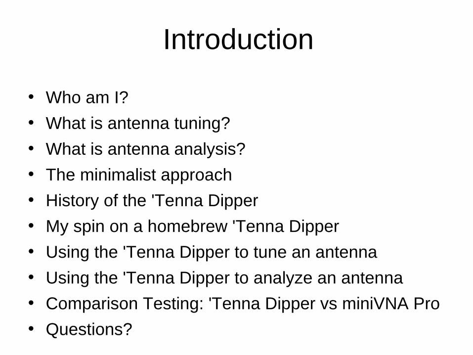
Introduction
• Who am I?
• What is antenna tuning?
• What is antenna analysis?
• The minimalist approach
• History of the 'Tenna Dipper
• My spin on a homebrew 'Tenna Dipper
• Using the 'Tenna Dipper to tune an antenna
• Using the 'Tenna Dipper to analyze an antenna
• Comparison Testing: 'Tenna Dipper vs miniVNA Pro
• Questions?
Who Am I?
• Kansas State University: BSEE '79, MSEE '81 (Digital signal processing and instrumentation)
• Motorola GED, Chandler AZ: '81 - '88
• Sunair Electronics, Ft. Lauderdale FL: '88 - '92 (Adaptive Link Establishment modem)
• '92 - Present: E-Systems/Raytheon IIS, Garland TX
• Technician and General Class: '09 - KF5DAF
• Amateur Extra: '10 – AE5PH
• Interests: SDR, home brewing, EMCOMM
What Is Antenna Tuning?
• Adjusting an antenna such that it is near or at resonance for a desired range of frequencies
• Adjusting an antenna such that it has nearly the same impedance of a connected radio for a desired range of frequencies
• Adjusting a transmatch to compensate for the impedance mismatch between an antenna and a radio for a desired range of frequencies
Using a Radio and SWR Meter Can Be Problematic
• Many radios and transmatches do not have built-in SWR meters (especially true for home brew radios)
• Good SWR meters can be expensive and fragile, either electrically, mechanically, or both
• Using a radio to tune the antenna may damage the radio, the SWR meter, or both
• An SWR meter is one more piece of radio gear to hook up (and transport, if in the field)
What Is Antenna Analysis?
• Determining the impedance of an antenna over a range of frequencies
• Determining the Voltage Standing Wave Ratio (VSWR) of an antenna over a range of frequencies
• Determining the resonant frequency (or frequencies) of an antenna
• Determining the gain pattern of an antenna
Using an Antenna Analyzer Can Be Problematic
• They can be expensive (good ones are very expensive) - $99 to $$$$
• Many antenna analyzers must be calibrated in order to produce reliable, realistic results
• The operator must use the antenna analyzer properly to obtain reliable, realistic results
• Improper use of an antenna analyzer can damage it, resulting in an expensive repair bill (or the purchase of a new analyzer, ouch!)
The Minimalist Approach
• Antenna tuning: Determine that an antenna or transmatch are adjusted such that the radio is not likely to be damaged during transmission for a desired range of frequencies
• Antenna analysis: Determine the range of frequencies that an antenna is unlikely to cause damage to the radio during transmission
• These similar goals can be accomplished with one, relatively simple and (potentially) inexpensive piece of test equipment: A Resistive SWR Bridge
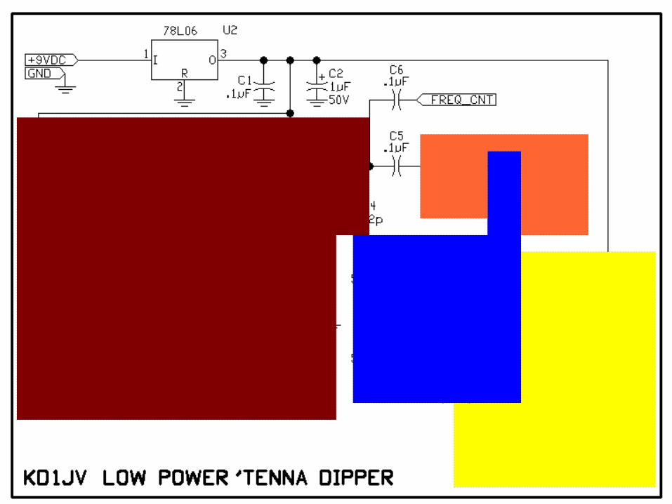
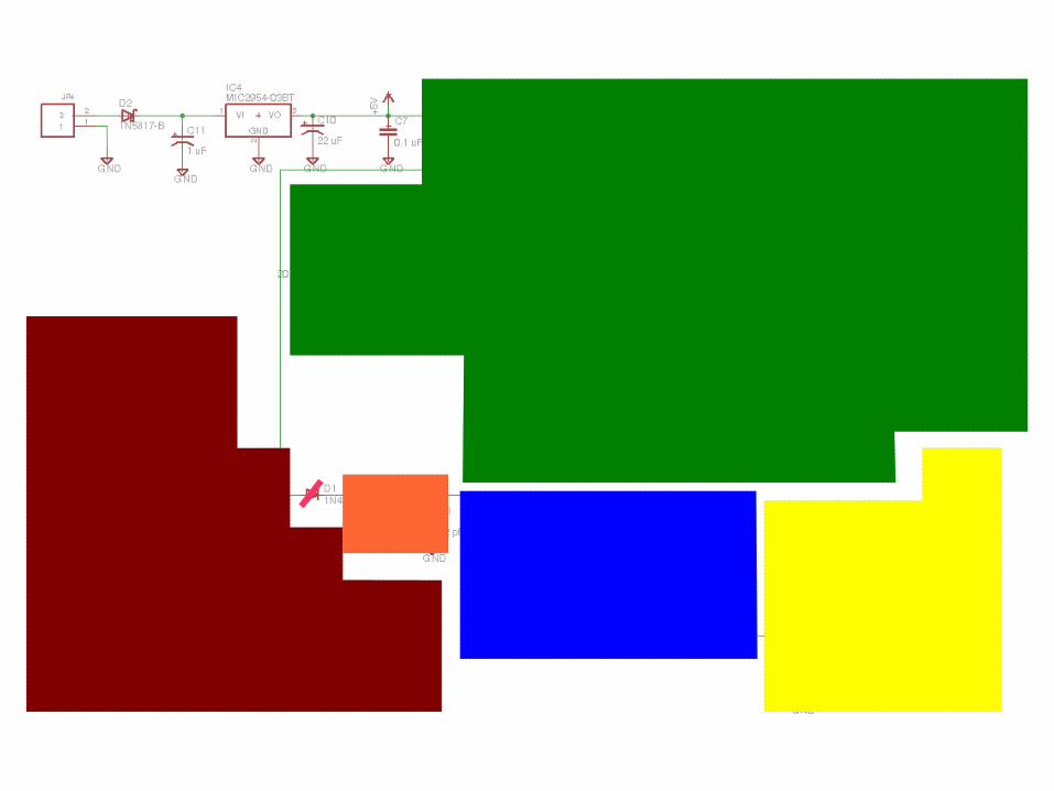
A Resistive SWR Bridge
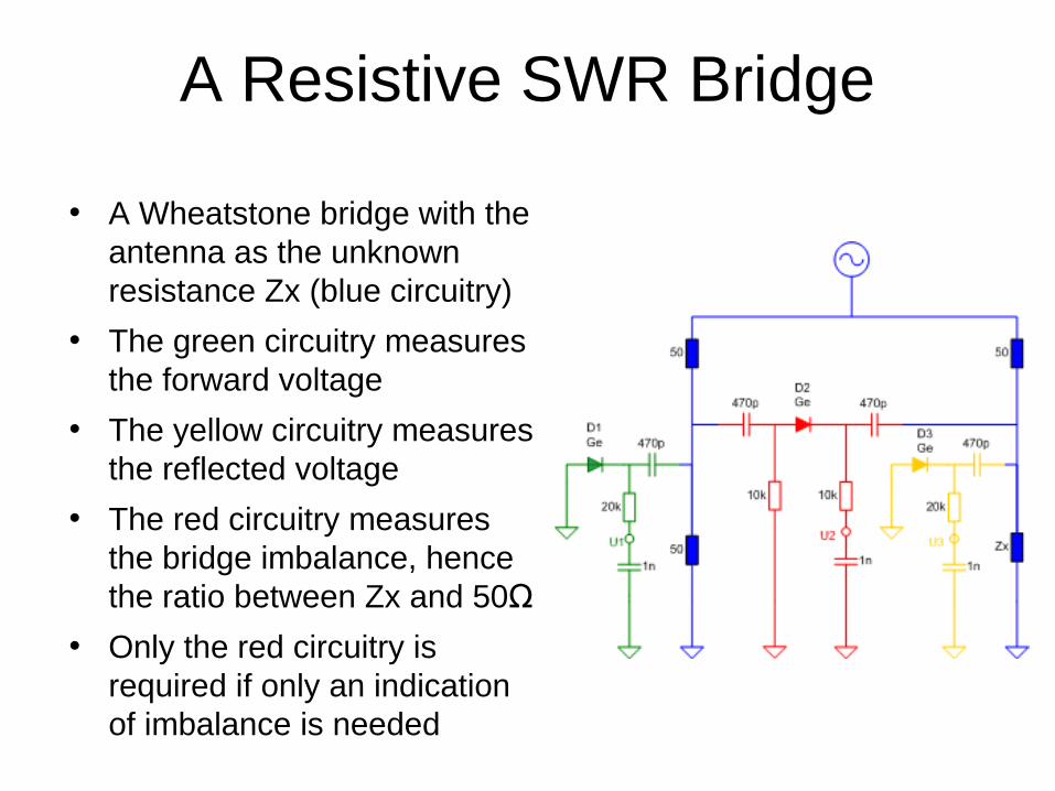
• A Wheatstone bridge with the antenna as the unknown resistance Zx (blue circuitry)
• The green circuitry measures the forward voltage
• The yellow circuitry measures the reflected voltage
• The red circuitry measures the bridge imbalance, hence the ratio between Zx and 50Ω
• Only the red circuitry is required if only an indication of imbalance is needed
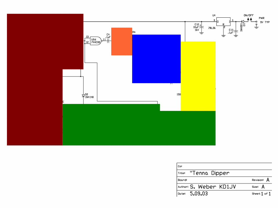
History Of The 'Tenna Dipper
• Created by Steve "Melt Solder" Weber, KD1JV
• A digital VCO (74HC46) drives an antenna resistance bridge (Harmonics? You betcha!)
• Four frequency bands are set by four trimmer pots forming a tapped voltage ladder, with another trimmer pot used for fine adjustments
• Two 2N3904 transistors, arranged as a Darlington pair, drive an LED to indicate the amount of antenna mismatch
• Provides a tap for your frequency meter
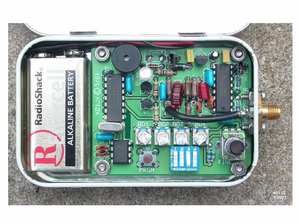
• Fits in an Altoids® tin with a 9V battery!
4SQRP 'Tenna Dipper Kit
• Commercialized version of the 'Tenna Dipper formerly sold by the Four State QRP Group
• Added a modified version of the Arizona ScQRPions Stinger frequency counter chip, which reports the frequency measured in Morse code at 27 WPM
• Isolates VCO and frequency counter from bridge via a logic gate
• Still fits in an Altoids® tin (if you trim the PCB) with a 9V battery
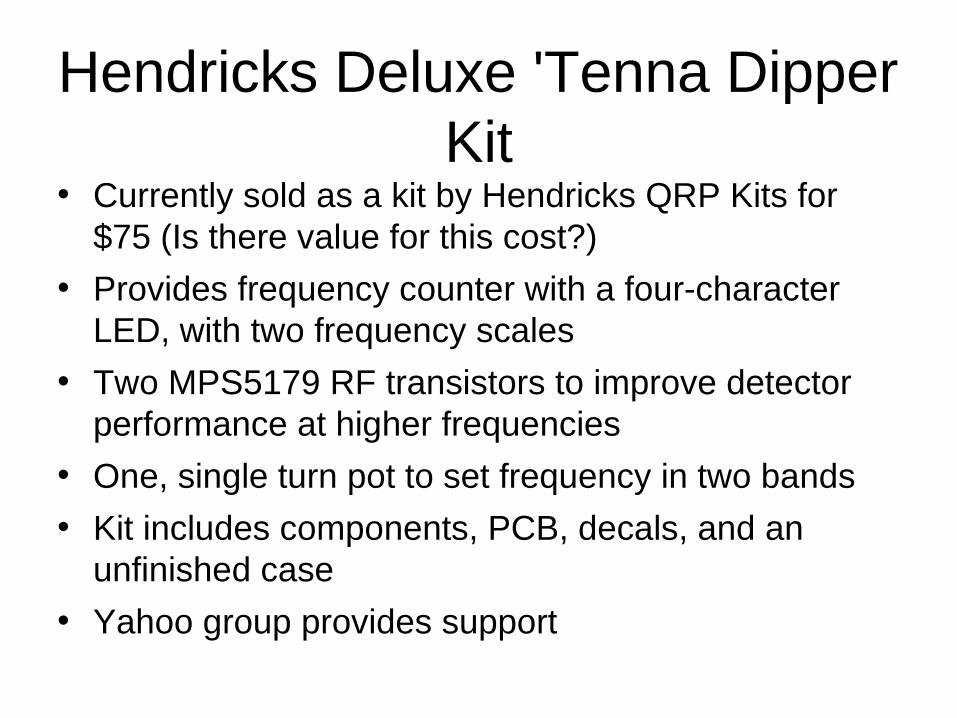
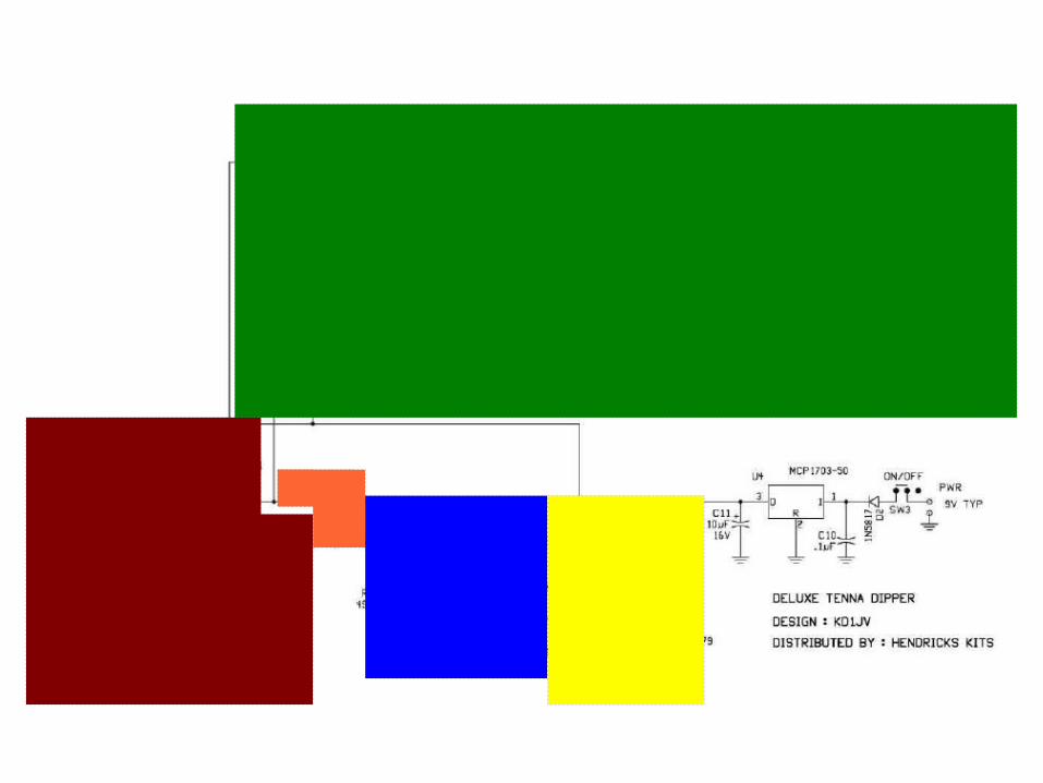
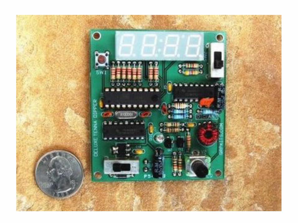
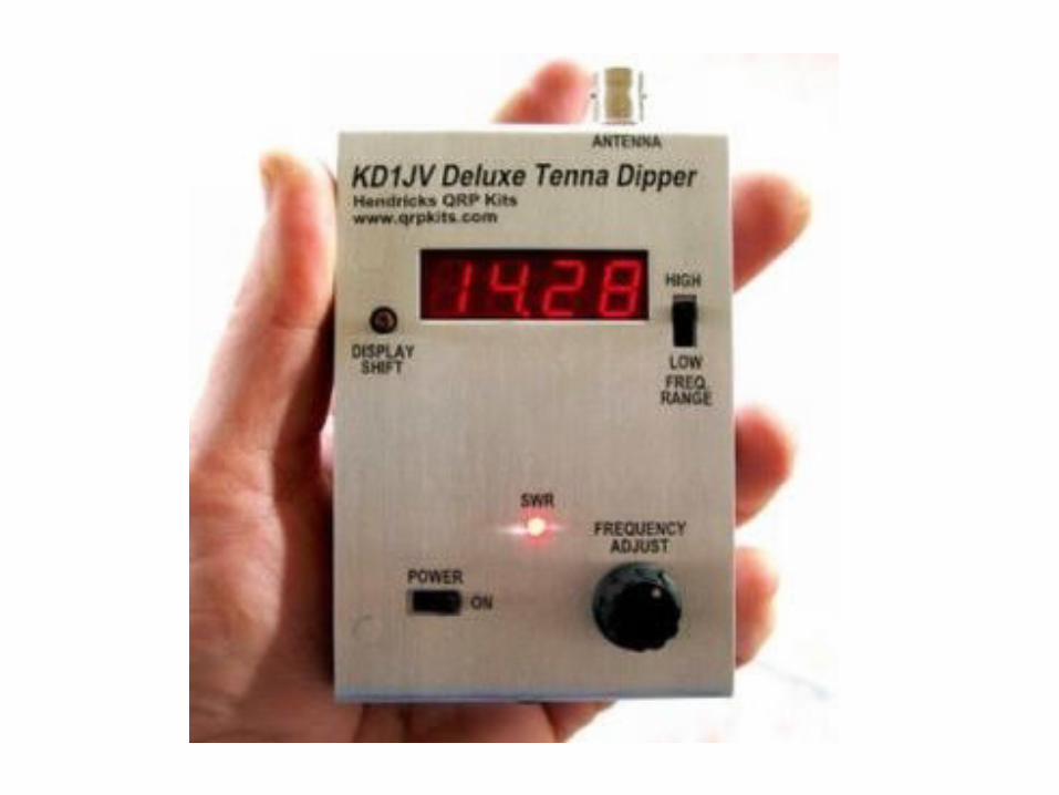
Hendricks Deluxe 'Tenna Dipper Kit
• Currently sold as a kit by Hendricks QRP Kits for $75 (Is there value for this cost?)
• Provides frequency counter with a four-character LED, with two frequency scales
• Two MPS5179 RF transistors to improve detector performance at higher frequencies
• One, single turn pot to set frequency in two bands
• Kit includes components, PCB, decals, and an unfinished case
• Yahoo group provides support
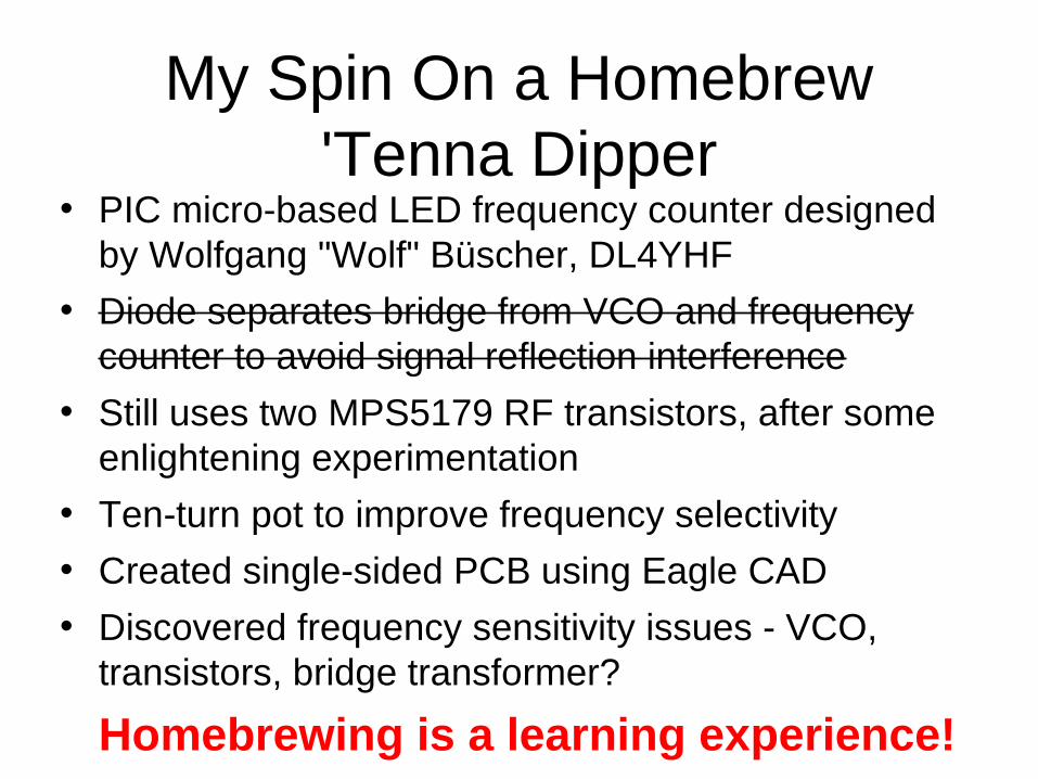
My Spin On a Homebrew'Tenna Dipper
• PIC micro-based LED frequency counter designed by Wolfgang "Wolf" Büscher, DL4YHF
• Diode separates bridge from VCO and frequency counter to avoid signal reflection interference
• Still uses two MPS5179 RF transistors, after some enlightening experimentation
• Ten-turn pot to improve frequency selectivity
• Created single-sided PCB using Eagle CAD
• Discovered frequency sensitivity issues - VCO, transistors, bridge transformer?
Homebrewing is a learning experience!
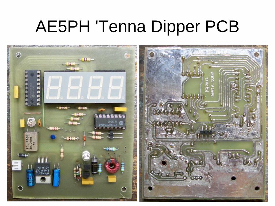
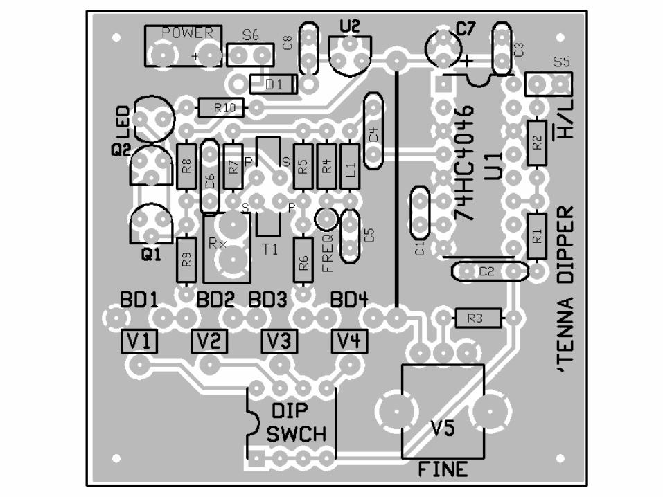
AE5PH 'Tenna Dipper PCB
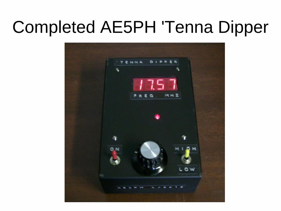
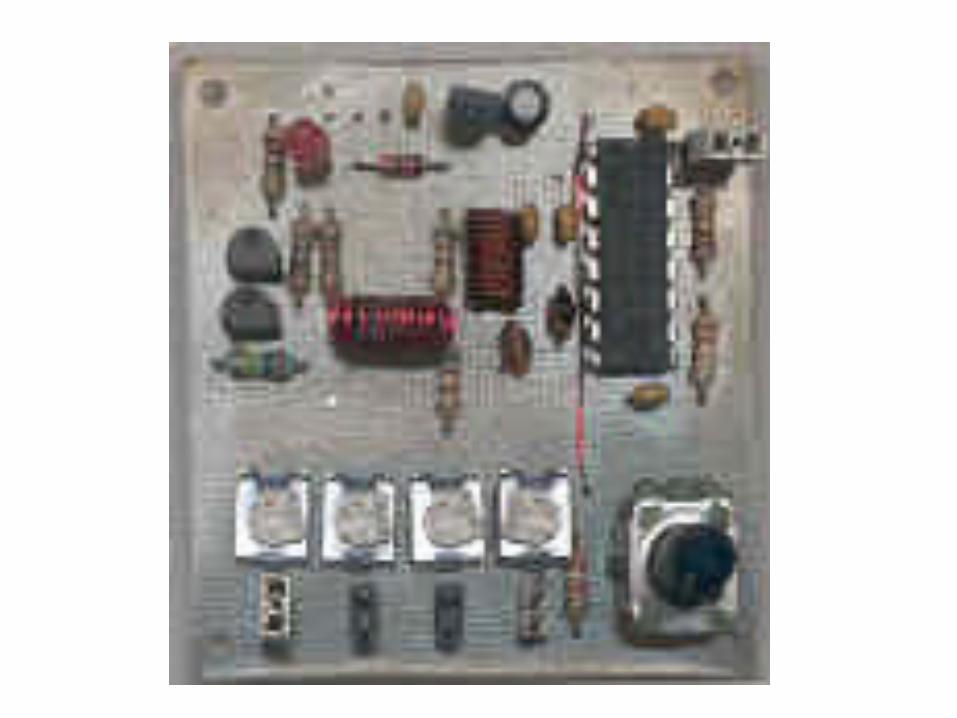
Completed AE5PH 'Tenna Dipper
0 5 10 15 20 25 30 35
0
0.01
0.01
0.02
0.02
0.03
0.03
0.04
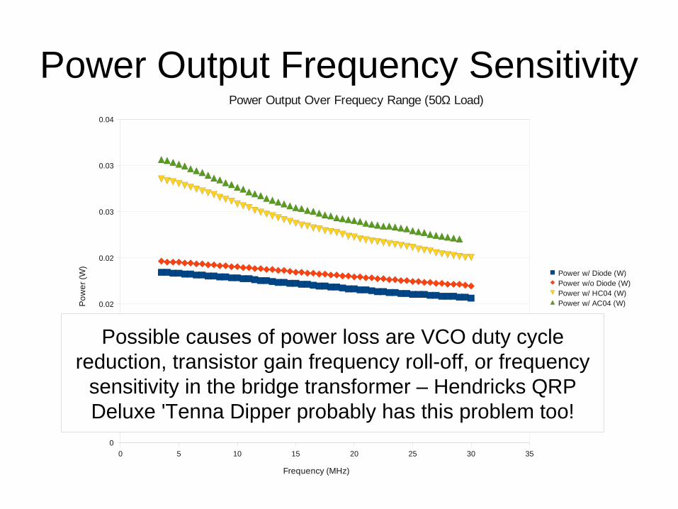
Power Output Over Frequecy Range (50Ω Load)
Power w/ Diode (W)Power w/o Diode (W)Power w/ HC04 (W)Power w/ AC04 (W)
Frequency (MHz)
Po
we
r (W
)Power Output Frequency Sensitivity
Possible causes of power loss are VCO duty cycle reduction, transistor gain frequency roll-off, or frequency
sensitivity in the bridge transformer – Hendricks QRP Deluxe 'Tenna Dipper probably has this problem too!
Using the 'Tenna Dipper to Tune an Antenna
• Select the frequency band and adjust the pot to display the desired frequency
• Adjust the antenna until the LED brightness "dips" to a minimum, or ...
• Adjust the transmatch until the LED brightness "dips" to a minimum
• Adjust the pot and watch the brightness of the LED and the frequency counter value to estimate the match frequency range
• Multiple LED "dips" may be due to VCO harmonics
Using the 'Tenna Dipper to Analyze an Antenna
• Switch between bands and adjust the pot until the LED brightness "dips" to a minimum
• The frequency counter displays a local maximum resonance point
• Adjust the pot and watch the LED brightness and the frequency counter to get a sense of the range of locally maximal resonance
• Perform this task over the frequencies of interest, as there may be multiple resonance points
• Multiple LED "dips" may be due to VCO harmonics
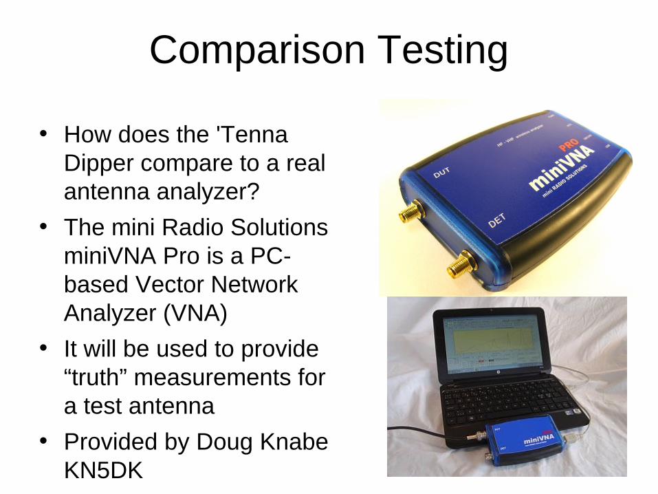
Comparison Testing
• How does the 'Tenna Dipper compare to a real antenna analyzer?
• The mini Radio Solutions miniVNA Pro is a PC-based Vector Network Analyzer (VNA)
• It will be used to provide “truth” measurements for a test antenna
• Provided by Doug Knabe KN5DK
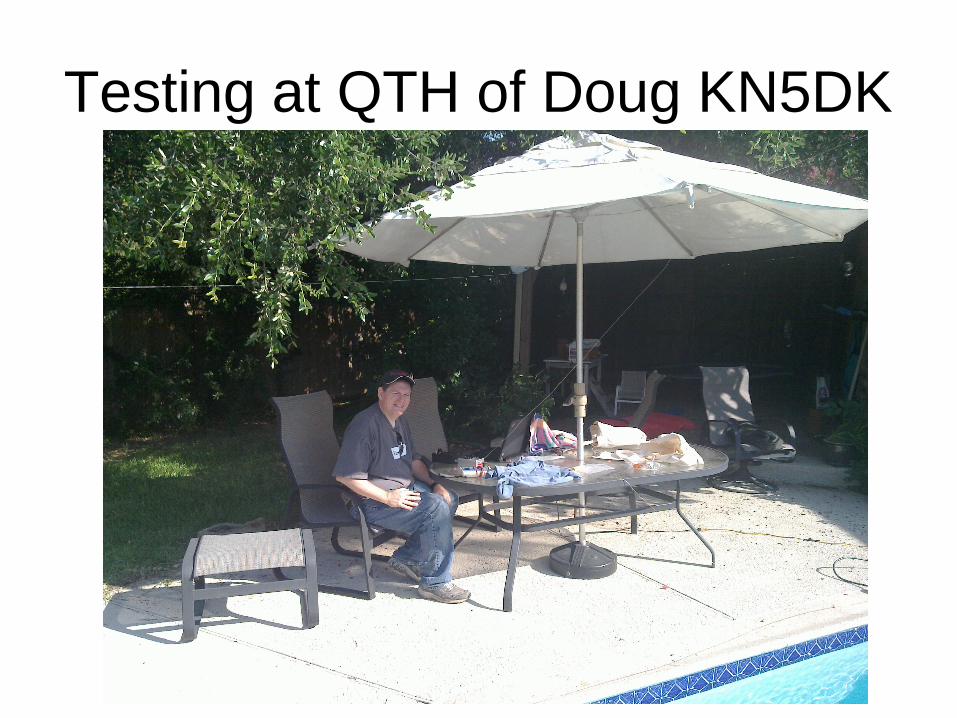
Testing at QTH of Doug KN5DK
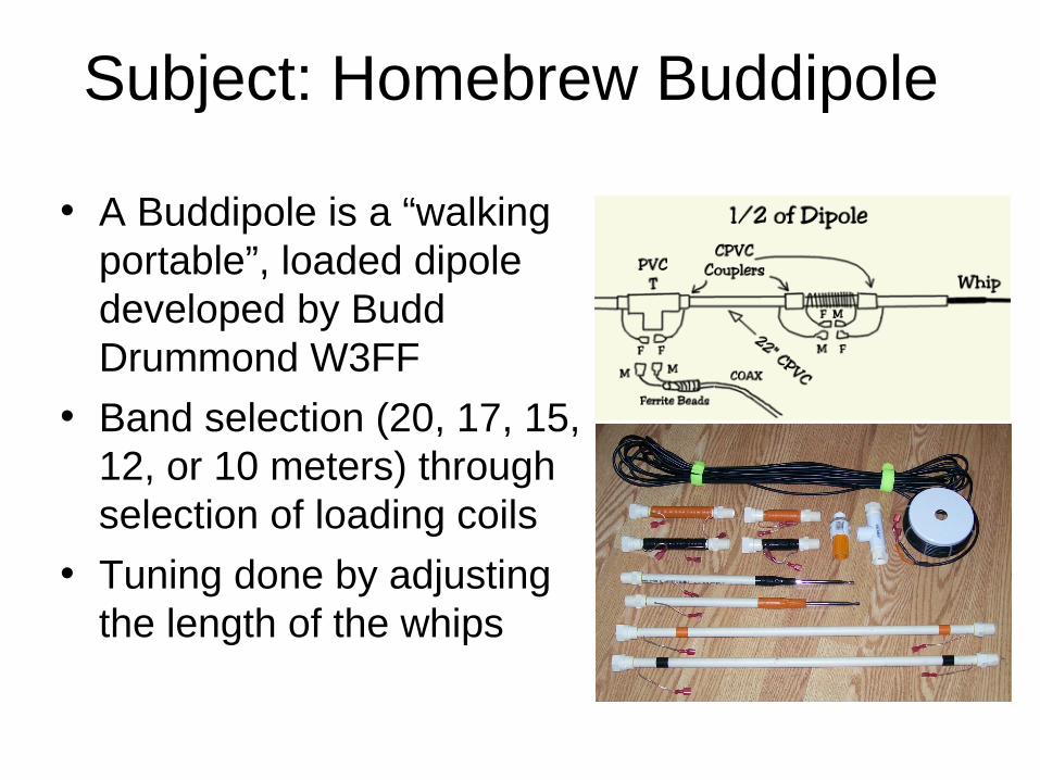
Subject: Homebrew Buddipole
• A Buddipole is a “walking portable”, loaded dipole developed by Budd Drummond W3FF
• Band selection (20, 17, 15, 12, or 10 meters) through selection of loading coils
• Tuning done by adjusting the length of the whips
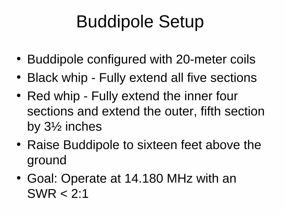
Buddipole Setup
• Buddipole configured with 20-meter coils
• Black whip - Fully extend all five sections
• Red whip - Fully extend the inner four sections and extend the outer, fifth section by 3½ inches
• Raise Buddipole to sixteen feet above the ground
• Goal: Operate at 14.180 MHz with an SWR < 2:1
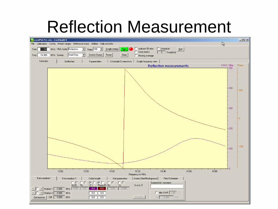
Reflection Measurement
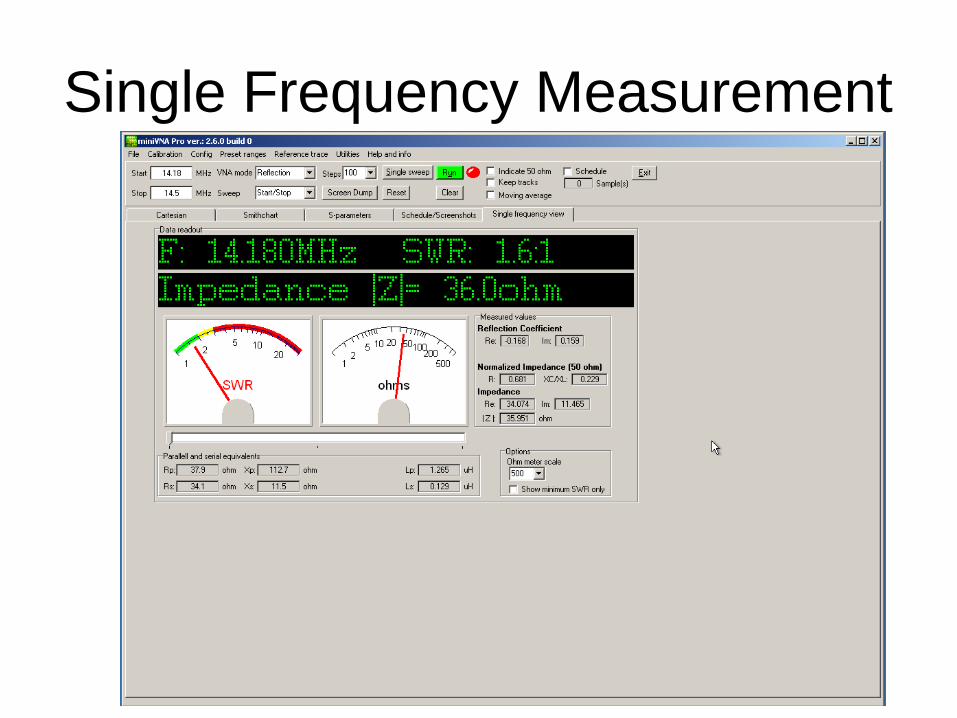
Single Frequency Measurement
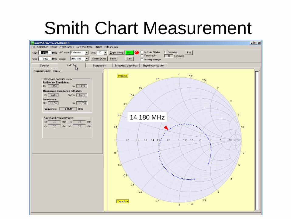
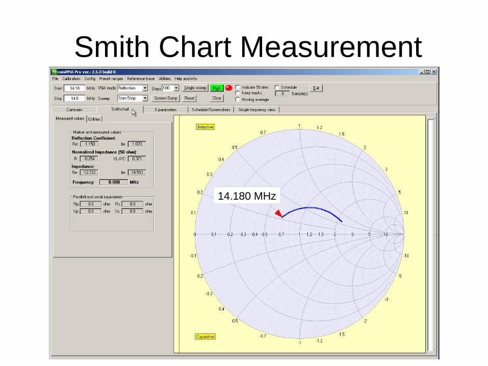
Smith Chart Measurement
14.180 MHz
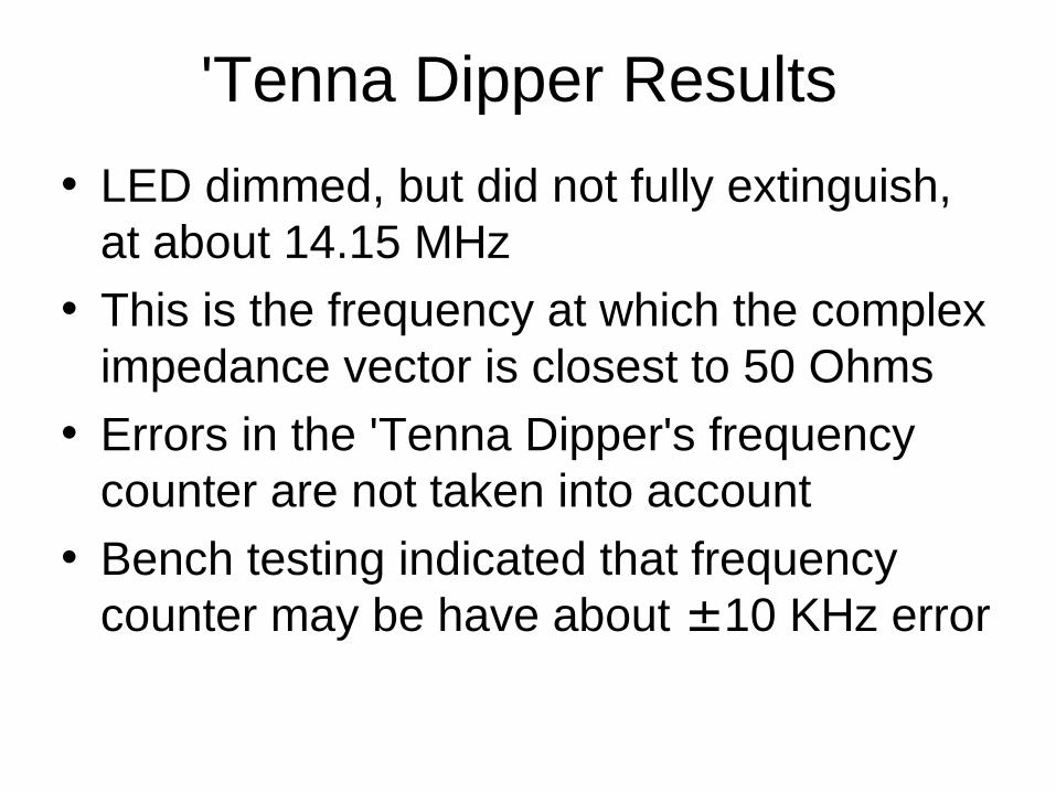
'Tenna Dipper Results
• LED dimmed, but did not fully extinguish, at about 14.15 MHz
• This is the frequency at which the complex impedance vector is closest to 50 Ohms
• Errors in the 'Tenna Dipper's frequency counter are not taken into account
• Bench testing indicated that frequency counter may be have about ±10 KHz error
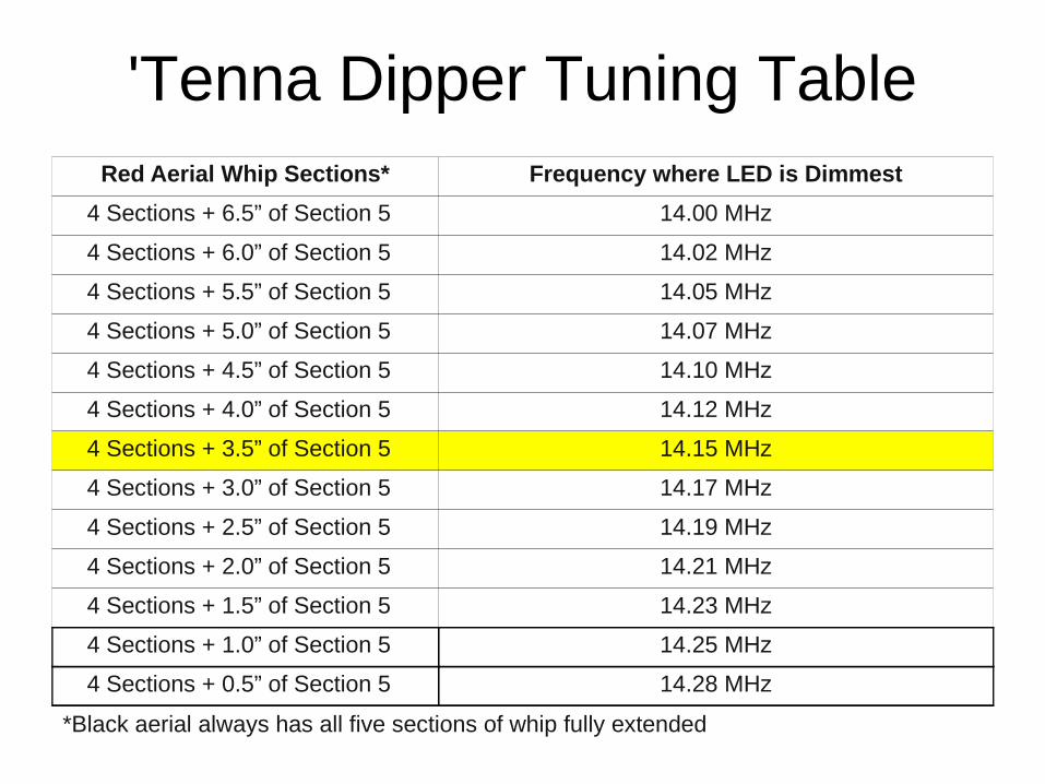
'Tenna Dipper Tuning TableRed Aerial Whip Sections* Frequency where LED is Dimmest
4 Sections + 6.5” of Section 5 14.00 MHz
4 Sections + 6.0” of Section 5 14.02 MHz
4 Sections + 5.5” of Section 5 14.05 MHz
4 Sections + 5.0” of Section 5 14.07 MHz
4 Sections + 4.5” of Section 5 14.10 MHz
4 Sections + 4.0” of Section 5 14.12 MHz
4 Sections + 3.5” of Section 5 14.15 MHz
4 Sections + 3.0” of Section 5 14.17 MHz
4 Sections + 2.5” of Section 5 14.19 MHz
4 Sections + 2.0” of Section 5 14.21 MHz
4 Sections + 1.5” of Section 5 14.23 MHz
4 Sections + 1.0” of Section 5 14.25 MHz
4 Sections + 0.5” of Section 5 14.28 MHz
*Black aerial always has all five sections of whip fully extended
Questions?
Thanks and 73, Mac / AE5PH
...and a big thanks to Doug Knabe KN5DK for his hospitality and support during testing!

Back-up Slides
Smith Chart Measurement
14.180 MHz