Subject: Principles of Refrigeration and Air...
38
Transcript of Subject: Principles of Refrigeration and Air...


LECTURE No. 16 & 17
DESIGN OF PIPING SYSTEMS :
Types of piping system : The piping systems are divided into two types :
Closed system : In a closed system chilled or hot water flowing through the coils ,heater ,chiller , boiler or other heat exchanger forms a closed recirculating loop as shown in the figure below . In close system water is not exposed to the atmospheric during its flowing process . The purpose of recirculating is to save water and energy .
Open system : In an open system the water ix expose to the atmosphere as shown in the figure below . For example ,chilled water come directly into contact with the cooled and dehumidified air in the air washer and condenser water is exposed to atmosphere in the cooling tower . Recirculation of water is used to save water and energy .
The close systems are consists of the following components :
1‐ Load unite which represents the terminal unite as cooling or heating coils or radiators
2‐ Source unite which represent the chiller in cooling system or the boiler and furnace in heating systems .
3‐Distribution systems which represents the piping and fitting of the piping systems .
4‐ Pump that used to circulate the water in the cooling or heating systems . It is usually of a centrifugal types with constant flow rates ( 0.3 l/s with 20 kPa up to hundreds of l/s and appropriate pressures .
5‐ Expansion tanks which are of two types
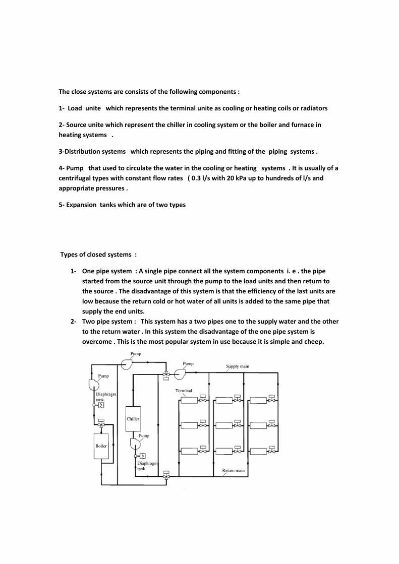
Types of closed systems :
1‐ One pipe system : A single pipe connect all the system components i. e . the pipe started from the source unit through the pump to the load units and then return to the source . The disadvantage of this system is that the efficiency of the last units are low because the return cold or hot water of all units is added to the same pipe that supply the end units.
2‐ Two pipe system : This system has a two pipes one to the supply water and the other to the return water . In this system the disadvantage of the one pipe system is overcome . This is the most popular system in use because it is simple and cheep.
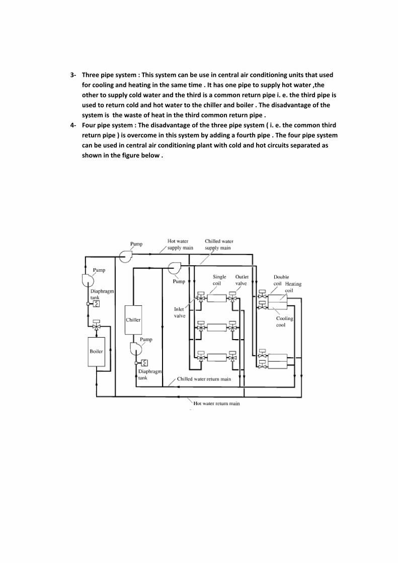
3‐ Three pipe system : This system can be use in central air conditioning units that used for cooling and heating in the same time . It has one pipe to supply hot water ,the other to supply cold water and the third is a common return pipe i. e. the third pipe is used to return cold and hot water to the chiller and boiler . The disadvantage of the system is the waste of heat in the third common return pipe .
4‐ Four pipe system : The disadvantage of the three pipe system ( i. e. the common third return pipe ) is overcome in this system by adding a fourth pipe . The four pipe system can be used in central air conditioning plant with cold and hot circuits separated as shown in the figure below .
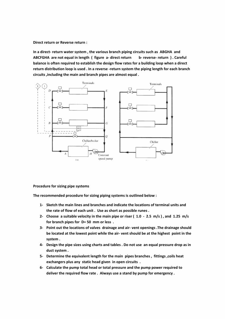
Direct return or Reverse return :
In a direct‐ return water system , the various branch piping circuits such as ABGHA and ABCFGHA are not equal in length ( figure a‐ direct return b‐ reverse‐ return ) . Careful balance is often required to establish the design flow rates for a building loop when a direct return distribution loop is used . In a reverse ‐return system the piping length for each branch circuits ,including the main and branch pipes are almost equal .
Procedure for sizing pipe systems
The recommended procedure for sizing piping systems is outlined below :
1‐ Sketch the main lines and branches and indicate the locations of terminal units and the rate of flow of each unit . Use as short as possible runes .
2‐ Choose a suitable velocity in the main pipe or riser ( 1.0 ‐ 2.5 m/s ) , and 1.25 m/s for branch pipes for D= 50 mm or less .
3‐ Point out the locations of valves drainage and air‐ vent openings .The drainage should be located at the lowest point while the air‐ vent should be at the highest point in the system .
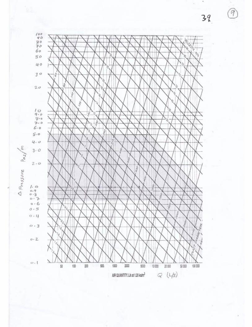
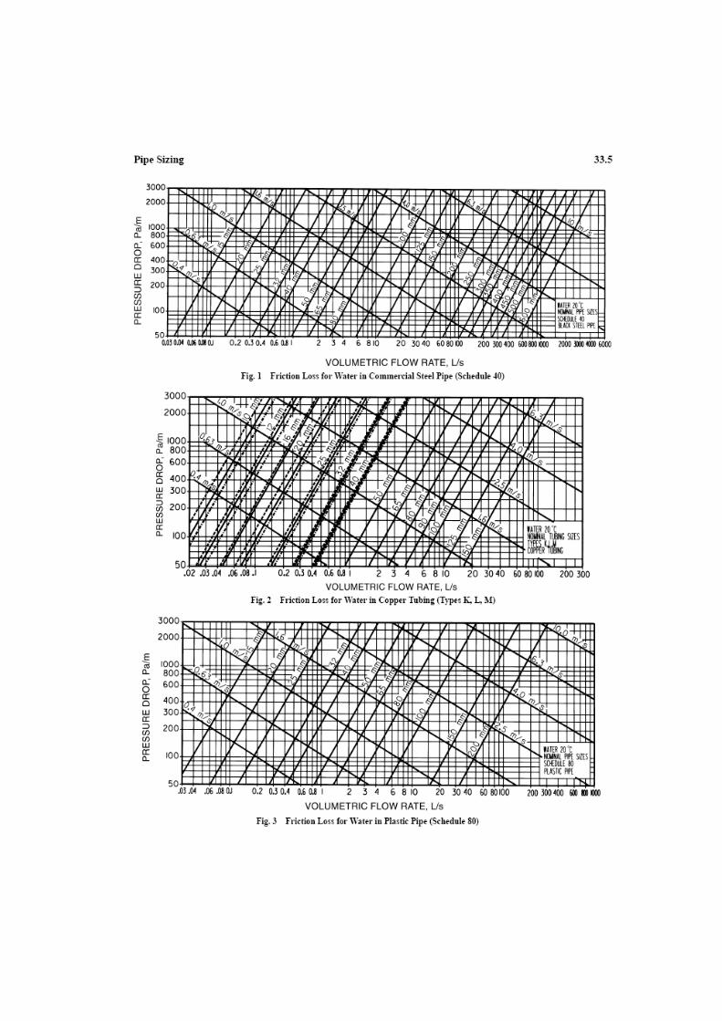
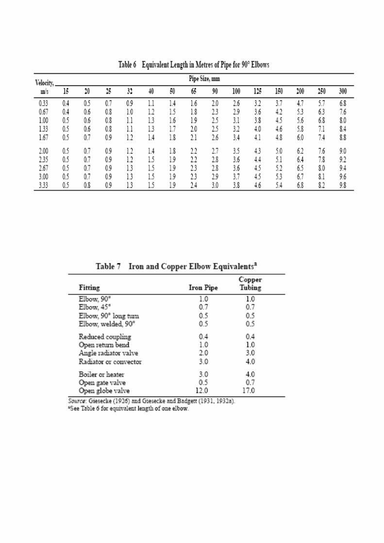
4‐ Design the pipe sizes using charts and tables . Do not use an equal pressure drop as in duct system .
5‐ Determine the equivalent length for the main pipes branches , fittings ,coils heat exchangers plus any static head given in open circuits .
6‐ Calculate the pump total head or total pressure and the pump power required to deliver the required flow rate . Always use a stand by pump for emergency .

Example ‐1
Determine the pressure drop in 90 elbow of 25 mm diameter . The water is flowing at mass flow rate of 0.5 kg/s and temperature of 60 c .
Example ‐2
Size the piping required to carry water mass flow rates such as ( 1, 10 , 30 , 50 kg/s ) at temperature of 5 c .
Water pumps :
The total head of a given pump may be determined by :
H pump = { H d + 0.5 *(VD )2/g ‐ ( Hs + 0.5 * ( Vs )
2/g ) }
Where H pump in meter of water and subscripts (d ) for discharge and (s) for suction sides .
P pump = { Pd + 0.5 * P * ( V d )2 ‐ ( Ps + 0.5 * p * ( V s )
2 ) }
Where P pump in Pascal and subscripts (d ) for discharge and (s) for suction sides .
The power of the pump may be given by :
W pump = M * g * H pump = Q * P pump in (Watt)
The pump efficiency may be given by :
η = W pump / W sh
Where : W sh is the shaft power of the pump .

Example ‐ 3
A pump is used in a closed system with flow rates of ( 7.6 l/s ) . The discharge pipe diameter is 68.7 mm and that for the suction side is (80.7 mm ) . The expansion tank is located at the suction side at a height of 15 m above the centerline of the pump suction pipe . There is a gauge pressure in the discharge side which reads (250 k Pa ) during the normal operation of the pump . Calculate the total pressure and the power of the pump .
Example – 4
A gauge pressure located at the inlet side of a cooling coil reads ( 100 k Pa ) . An other gauge pressure is located at the exit side at a height of ( 1.0 m ) above the location of the inlet side gauge. The exit side gauge pressure reads ( 50 k Pa ) . Calculate the pressure drop for the cooling coil .
Example ‐5
Determine the equivalent length of ,gate valve of ( D =50 mm ) , a union of ( D= 50 mm ) and T‐ connection of (D= 500 ) with flow rate of 1.0 kg/s .
Example ‐6
A piping system consist of a pump , a chiller , three cooling coils connected in series .The expansion tank is located at suction side of the pump at a height of (10 m ) above the center line of the suction pipe of the pump . There is (10 ) gate valves , ( 20 ) elbow 90 in the circuits . The longest pipe run is 100 m length . Calculate the total pressure and pumping power for the system .

Lectures No 18 – : Refrigeration Systems
Refrigeration : Is the process of removing heat from matter which may be solid , a liquid or a gas . Removing heat from the matter cools or lower its temperature.
Refrigeration machine : The refrigeration machine is a reversible heat engine that run in a reversed direction as shown in the figure below . The refrigerator absorb heat Qc from the heat source at a temperature TC and reject heat QH to the heat sink at temperature TH . Work must be done on the system to do such process .
Application of the second law gives :
QH – Qc = W or
QH = Qc + W
This equation represent the fundamental balance of a refrigeration machine . The performance of a refrigeration machine is expressed as the ratio of useful heat (refrigeration effect ) to the input work .
C. O. P. = Refrigeration effect ( Q c ) / Input work ( W )

Carnot refrigeration cycle :
The Carnot cycle is a theoretical model that useful for understanding a refrigeration cycle . In some applications the Carnot refrigeration cycle is known as the reverse Carnot cycle . The following processes take place in the Carnot refrigeration cycle as shown in the figure below :
1‐2 is the ideal compression at constant entropy .
2‐3 Is the rejection of heat in the condenser at a constant condensation temperature
3‐4 Is the ideal expansion at constant entropy .
4‐1 Is the absorption of heat in the evaporator at a constant evaporation temperature
QH = TH ( S2 – S3 )
QC = TC ( S1 – S4 ) S2 – S3 = S1 – S4
W = QH ‐ QC = ( TH – TC ) ( S1 – S4 )
C. O. P Carnot = QC / W = TC / ( TH – TC ) Where temperatures in Kelvin (K)
Refrigerants :
Refrigerant is the fluid that circulate in the refrigeration machine and absorbing heat during evaporation. These refrigerants which provide a cooling effect during the phase change from liquid to vapor are commonly use in refrigeration , air conditioning and heat pupm systems .. In selection the appropriate refrigerant it expected to meet the following conditions :
1‐Ozone and environment friendly
2‐Low boiling point
3‐Low volume flow rate per unit capacity
4‐Vaporization pressure lower than atmospheric pressure
5‐High latent heat of vaporization
6‐Non‐flamable and non toxic
7‐Non‐reactive with lubrication oils of compressor
8‐High critical point
9‐Low cost
10‐Detectable in case of leakage .
There are several types of refrigerant that are :
1‐ Halocarbons such as Freon (R 11) and (R12) and (R22) 2‐ Hydrocarbons such as methane (R50),Propane (R290) and Butane (R600) 3‐ Inorganic such Ammonia (R717) ,CO2 (R744) and Air (R729) .
Saturation Vapor Compression Refrigeration Cycle:
The reversed Carnot cycle with vapor as refrigerant can be used as practical cycle with minor modifications that are :
1‐The isothermal processes of heat rejection and absorption accompany condensation and evaporation are nearly perfect processes and easily achieved in practice .
2‐ The isentropic compression and expansion processes however have certain limitations which are :
a‐ Dry versus wet compression because wet compression may damage the compressor since liquid cannot be compressed easily .
b‐ Throttling versus isentropic expansion ,because the expansion required a turbine and the work of the turbine is so small therefore throttling is preferable .
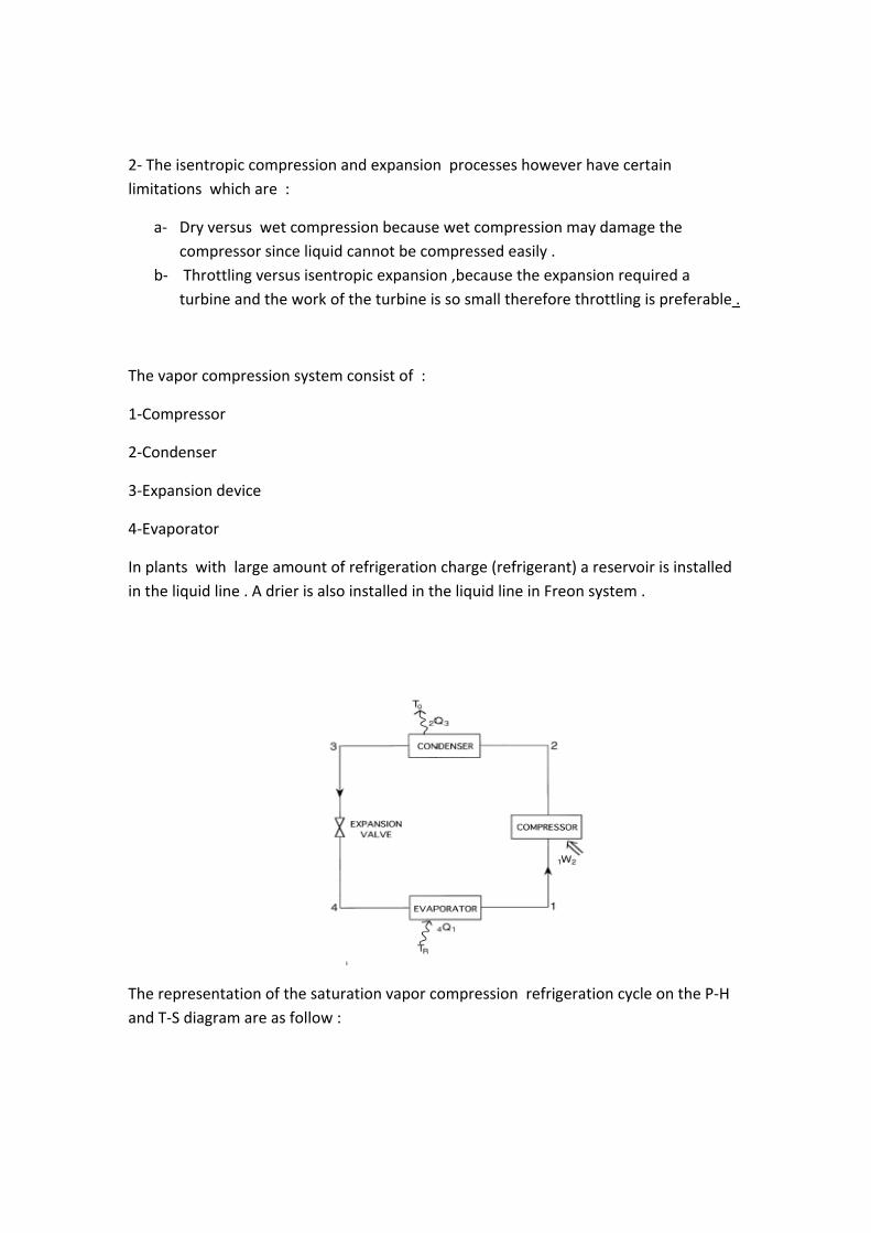
The vapor compression system consist of :
1‐Compressor
2‐Condenser
3‐Expansion device
4‐Evaporator
In plants with large amount of refrigeration charge (refrigerant) a reservoir is installed in the liquid line . A drier is also installed in the liquid line in Freon system .
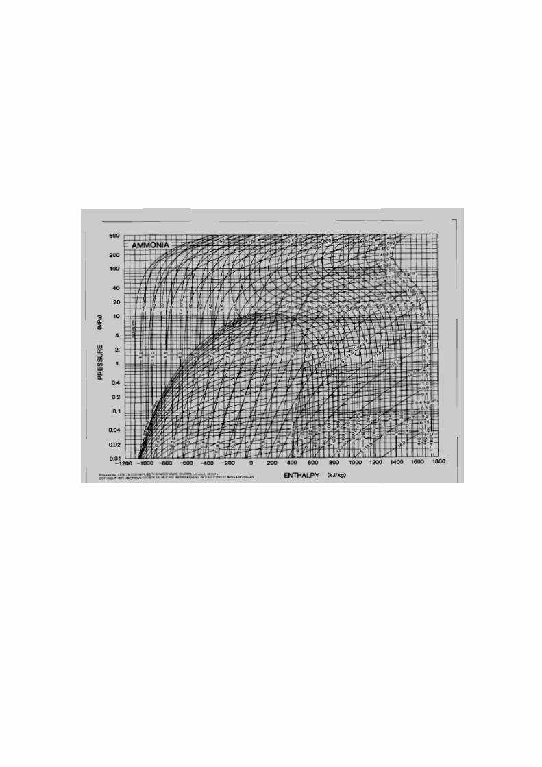
The representation of the saturation vapor compression refrigeration cycle on the P‐H and T‐S diagram are as follow :
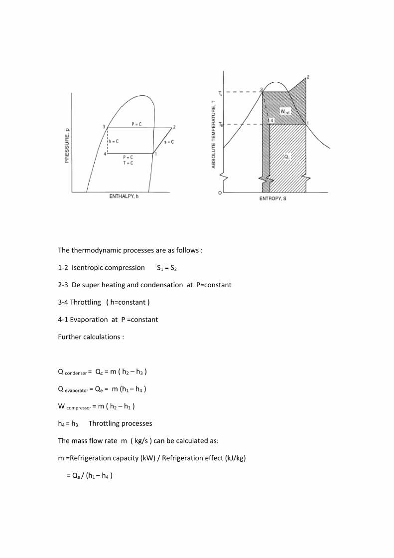
The thermodynamic processes are as follows :
1‐2 Isentropic compression S1 = S2
2‐3 De super heating and condensation at P=constant
3‐4 Throttling ( h=constant )
4‐1 Evaporation at P =constant
Further calculations :
Q condenser = Qc = m ( h2 – h3 )
Q evaporator = Qe = m (h1 – h4 )
W compressor = m ( h2 – h1 )
h4 = h3 Throttling processes
The mass flow rate m ( kg/s ) can be calculated as:
m =Refrigeration capacity (kW) / Refrigeration effect (kJ/kg)
= Qe / (h1 – h4 )
C.O.P. = Qe / W = (h1 – h4 )/ ( h1 – h2 )
Piston displacement of the compressor can be given by :
Vp = π (D2/4) L N / 60 = m v / ηv
Where ηv is the volumetric effiency , v is the specific volume at point 1 (m3/kg )
L and D is the stroke and diameter of the piston
N is the revolution per minute r .p..m
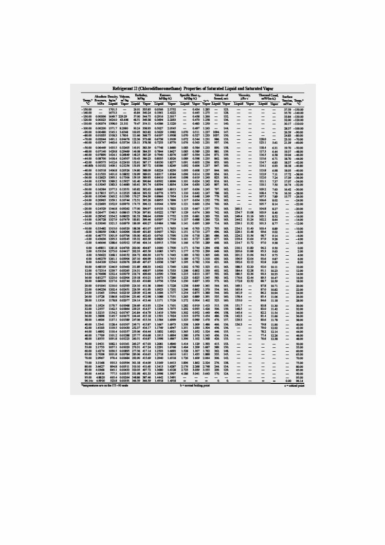
The values of enthalpies can obtained either from Charts or tables .
If tables are used then :
h1 = hg the evaporator temperature (the low temperature )
h3 = hf at the condenser temperature (the high temperature )
h4 = h3 Throttling processe
h2 = hg at condenser temperature + cp ( T2 – Tcondenser )
T2 can be found from :
S1 = S2 = Sg at condenser temperature + Cp Ln ( T2 / T condenser )
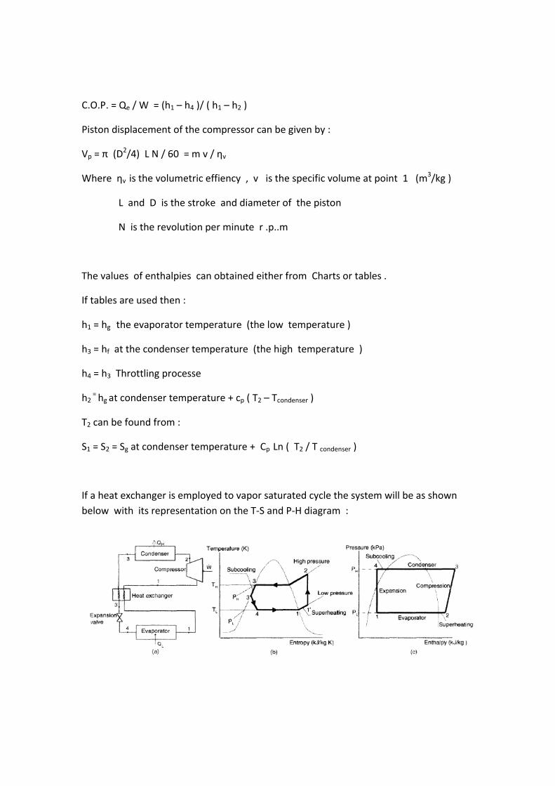
If a heat exchanger is employed to vapor saturated cycle the system will be as shown below with its representation on the T‐S and P‐H diagram :
Examples :
1‐A reversed Carnot cycle required 14.0 kW for 10 TR refrigeration . The temperature of the low temperature source is (‐ 20 c ) . Calculate :
a‐ C.O.P. of the Carnot cycle b‐ Temperature of the high temperature source c‐ The heat rejection in kW d‐ If the device works as a heat pump what is its C.O.P. for heating e‐ Show that C.O.P Heating= 1.0 + C.O.P cooling
2‐A refrigerator working on the saturated vapor compression refrigeration cycle .Its refrigeration capacity is ( 15 kW ). It works with evaporator temperature of ( ‐5 c ) and condenser temperature of ( 35 c ) .The refrigerator use R 12 as a refrigerant . Determine :
a‐ The mass flow rates of the refrigerants R12 ( m kg/s) b‐ The work of the compressor c‐ The heat rejected in the condenser d‐ C.O.P e‐ C.O.P Carnot
3‐A vapor compression refrigeration cycle work with R12 as a refrigerant .The refrigeration capacity of this cycle is ( 15 kW ) .The evaporator temperature is ( ‐5 c ) and the condenser temperature is ( 35 c ) . The vapor enter the compressor as a super heated vapor at ( 5 c ) above its evaporator temperature . The liquid refrigerant leave the condenser in sub cooled state with ( 4 c ) lower than its condenser temperature . Calculate :
a‐ The heat rejected at the condenser b‐ The work done by the compressor c‐ The piston displacement of the compressor V p = m v1 d‐ C.O.P of the cycle.
4‐A vapor compression refrigeration system working with ( R 12 ) as a refrigerant . The condenser temperature is ( 35 c ) while the evaporator temperature is ( ‐15 c ) . A heat exchanger is used in this system where the vapor enter the compressor as a super heat vapor at a temperature of ( 15 c ) . Calculate the C.O.P. and the hours power of the system .Note that in heat exchanger , Heat gained = Heat rejected.
5‐Ice store for fish work with Ammonia ( R 717 ) as a refrigerant . The temperature of freezing for fish is ( ‐ 20 c ) . The condenser of the system is cooled by water and has a pressure of ( 1352 k Pa ) . The system has a heat exchanger in which the liquid ammonia is sub cooled by ( ( 5 c ) . If the refrigeration capacity of the system is ( 20 kW ) find C.O.P and m water (kg/s ) in the condenser if the water temperature difference is ( 5 c ).
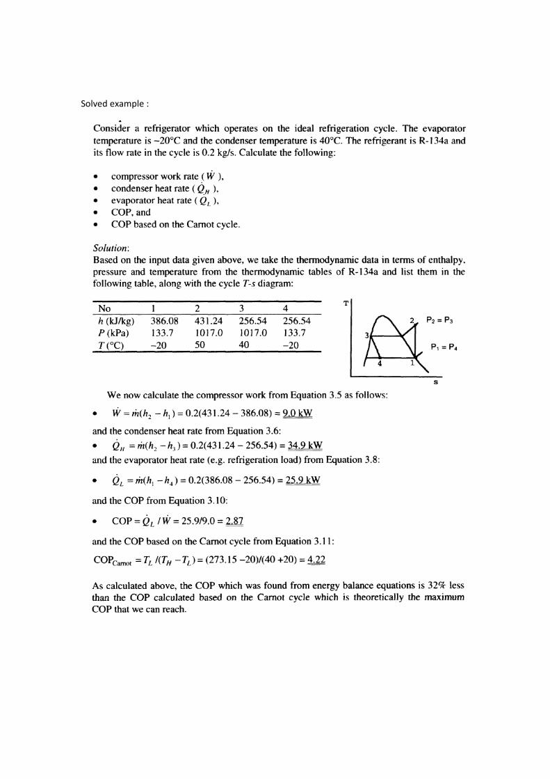
Solved example :

A actual Vapor Compression Refrigeration Cycle :
The actual vapor compression refrigeration cycle is shown in the following figure . In this actual system the pressures of the condenser and evaporator are no constant due to the presence of friction loss . The compression process in the compressor is accomplished with heat transfer loss and friction loss too , therefore it is not isentropic .

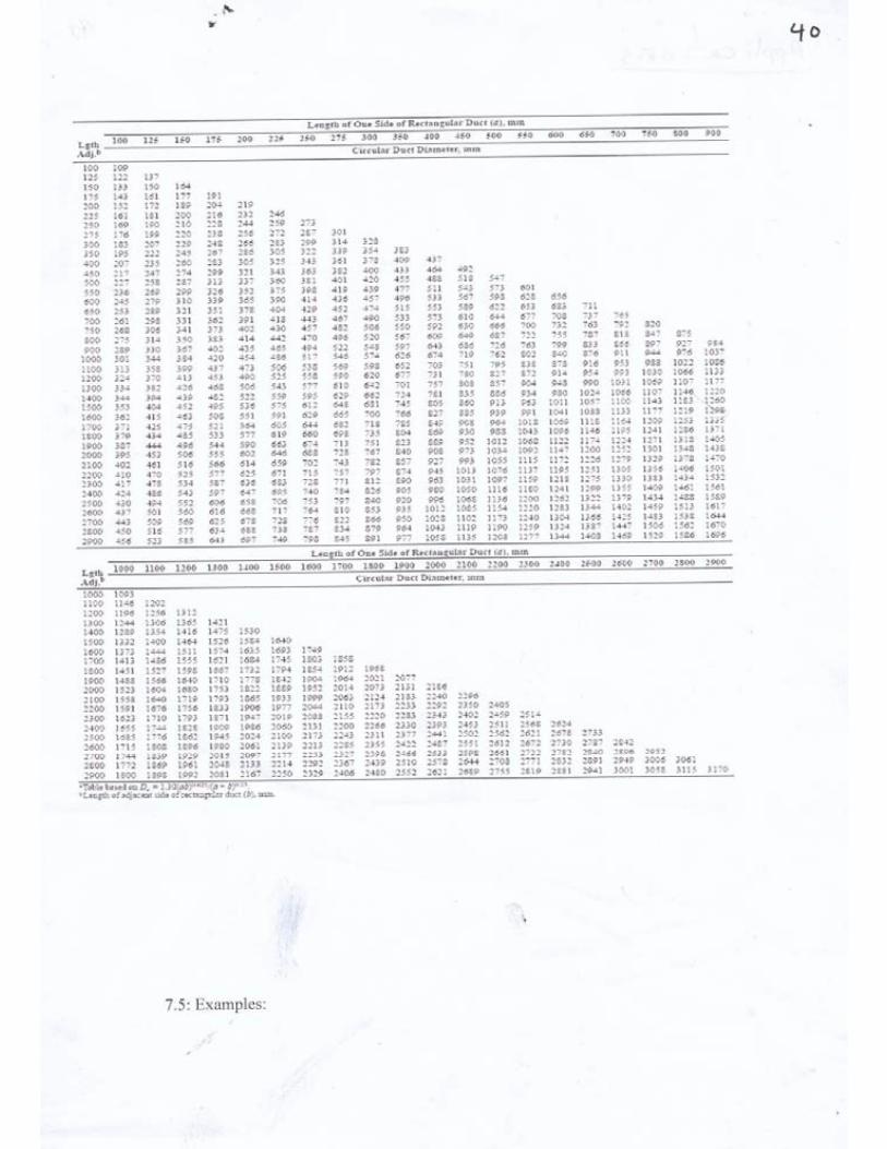
Tabl
les and Charrts :


Lecture No. 30
Refrigeration Equipments
The refrigeration equipments consists of the following components with some other aided and complementary parts :
1‐Compressors :
It is the heart of the refrigeration system which circulate the refrigerant through the system parts to do the required refrigeration effects . There are several types of compressor that are :
a‐Reciprocating compressors
b‐Scroll compressors
c‐Rotary compressors
d‐Screw compressors
e‐ Centrifugal compressors
Type (a ) is the most common one in small to moderate capacities systems . For large refrigeration capacities the centrifugal compressor is most appropriate compressor ,however it required a great amount of electricity to work .
Characteristic rotary scroll reciprocating screw centrifugal
Typical capacity < 5 TR 5‐10 TR 1‐ 150 TR 100‐750 TR 100‐10000 TR
Max. capacity 5 TR 10 TR 400 TR 2000 TR 20000 TR
Displacement positive positive positive positive not positive
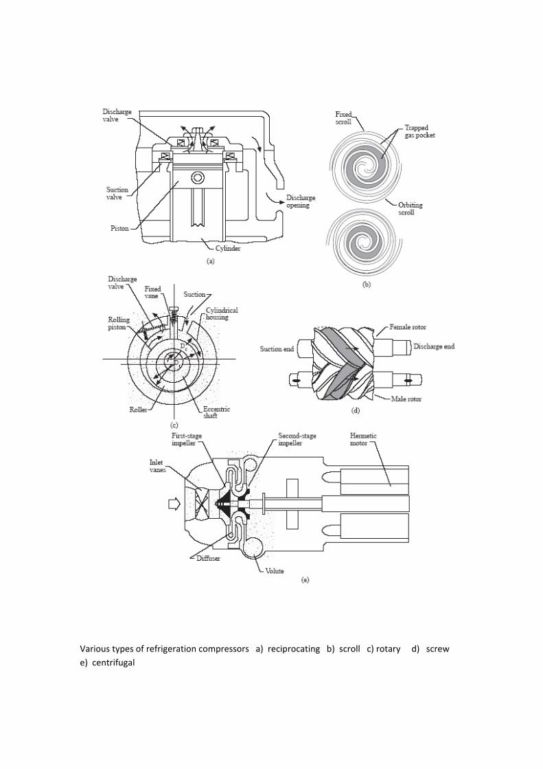
Various types of refrigeration compressors a) reciprocating b) scroll c) rotary d) screw e) centrifugal

2‐ Condensers :
The second component in the refrigeration system is the condenser . It is a device where the vapor refrigerant that coming from the compressor at high pressure and temperature is to be condensed and become in a liquid state with lower temperature and approximately the same high pressure of the compressor except the pressure losses due to friction in condenser pipes and fittings .The condenser is cooled by air in small capacities systems while the water is used for large ones . There are several types of condensers in use in the refrigeration systems that are :
a‐ Air cooled condenser .
b‐Shell and tube water cooled condenser s .
c‐ Evaporative condenser .
In air cooled condensers air is used to absorb the latent heat of condensation released during de‐superheating, condensation and sub‐cooling.
In water cooled condensers , latent heat of condensation released from the refrigerant during condensation is extracted by water . This cooling water often called condenser water is taken directly from river ,lake ,sea ,underground well or a cooling tower to cool the hot water that come out of the condenser to use it again in the system .
In an evaporative condenser uses the evaporation of water on the outer surface of the condensig tubes to remove the latent heat of condensation of the refrigerant during condensation .
An evaporative condenser is actually a combination of water‐cooled condenser and a cooling tower . It is usually located on the rooftop and should be near the compressor as possible .
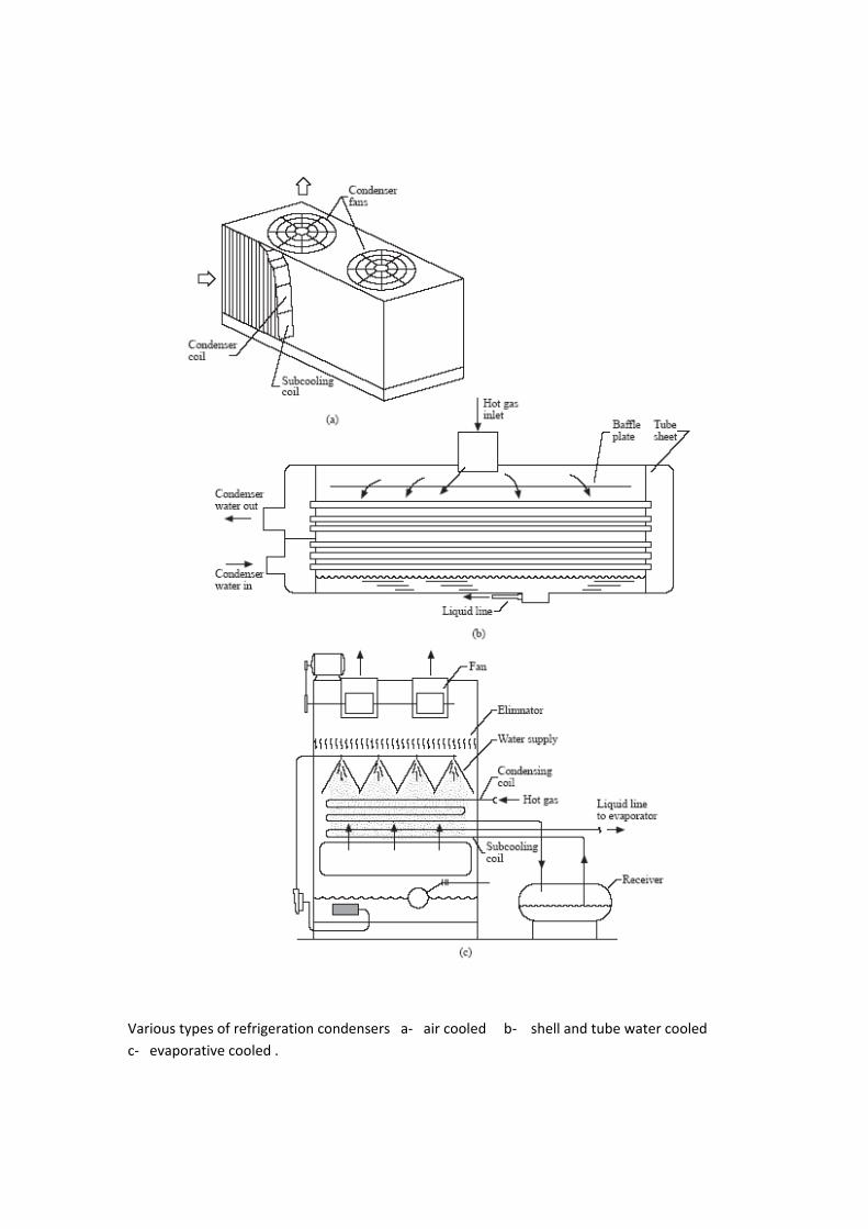
Various types of refrigeration condensers a‐ air cooled b‐ shell and tube water cooled c‐ evaporative cooled .
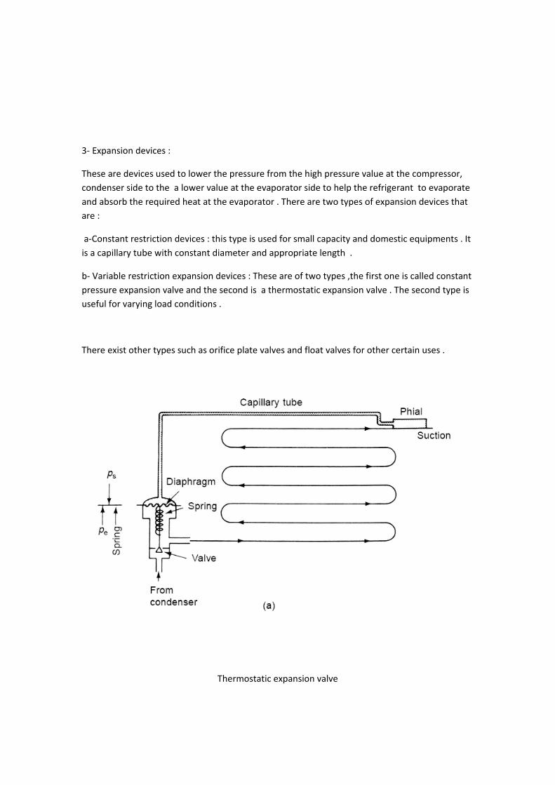
3‐ Expansion devices :
These are devices used to lower the pressure from the high pressure value at the compressor, condenser side to the a lower value at the evaporator side to help the refrigerant to evaporate and absorb the required heat at the evaporator . There are two types of expansion devices that are :
a‐Constant restriction devices : this type is used for small capacity and domestic equipments . It is a capillary tube with constant diameter and appropriate length .
b‐ Variable restriction expansion devices : These are of two types ,the first one is called constant pressure expansion valve and the second is a thermostatic expansion valve . The second type is useful for varying load conditions .
There exist other types such as orifice plate valves and float valves for other certain uses .
Thermostatic expansion valve
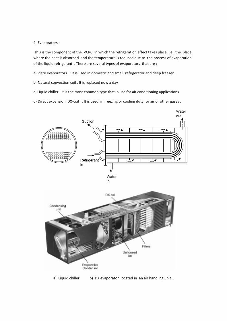
4‐ Evaporators :
This is the component of the VCRC in which the refrigeration effect takes place i.e. the place where the heat is absorbed and the temperature is reduced due to the process of evaporation of the liquid refrigerant . There are several types of evaporators that are :
a‐ Plate evaporators : It is used in domestic and small refrigerator and deep freezer .
b‐ Natural convection coil : It is replaced now a day
c‐ Liquid chiller : It is the most common type that in use for air conditioning applications
d‐ Direct expansion DX‐coil : It is used in freezing or cooling duty for air or other gases .
a) Liquid chiller b) DX evaporator located in an air handling unit .

5‐ Cooling towers :
This is an equipment that be used to cool the water of the VCRS condensers or any other heat exchange process . The tower cooled the water by spraying it in an air stream across several layers of backing . These layers are used to increase the surface area of heat transfer and to break the water jets into small droplets for more contact .The evaporation of the droplet surface leads to cool the rest of water and increases the DBT and humidity of the outgoing air .There are several types of towers that are :
a‐ Natural cooling tower : The air is crossing the tower naturally by wind speed .
b‐ Forced draft tower : The air is forced to the tower by fans .
c‐Induced draft tower : The air is induced from the tower by fans.