Study on Carbide Cutting Tool Life Using Various Cutting Speeds
7
Research paper 600 © Copyright by International OCSCO World Press. All rights reserved. 2012 VOLUME 55 ISSUE 2 December 2012 of Achievements in Materials and Manufacturing Engineering of Achievements in Materials and Manufacturing Engineering Study on carbide cutting tool life using various cutting speeds for α-β Ti-alloy machining K.B. Ahsan, A.M. Mazid, R.E. Clegg, G.K.H. Pang Central Queensland University, School of Engineering and Built Environment, Rockhampton, Australia * Corresponding e-mail address: [email protected] Received 17.10.2012; published in revised form 01.12.2012 Analysis and modelling ABSTRACT Current experimental studies have yielded that cutting speed, using carbide cutters, has no significant influence on surface roughness obtained for machining the α-β Titanium alloy Ti-6Al-4V. This paper presents results of experimental investigations carried out on the widely used titanium alloy Ti-6Al-4V using variable cutting speeds as well as different cutting tools at a constant feed rate and depth of cut. The effects of varying cutting speeds on the tool life have been analysed by inspecting the surface roughness of the machined samples and the tool wear observed during machining. As the cutting speed increases, the tool life drops off very rapidly and at higher cutting speed the chips start to ignite because of high heat generation at the cutting zone which is mainly caused by the low thermal conductivity of titanium alloys as postulated. Consequently higher cutting speeds may be used to dramatically reduce the production costs, but the currently available cutting tools will have a very poor tool life. According to this study, it has been identified that the uncoated carbide tool life is comparatively better than that of coated ones at lower cutting speeds whereas the coated ones are preferable at higher cutting speeds. It is expected that the metal manufacturing industries will be highly benefitted by this outcome in selecting the appropriate cutting tool as well as cutting speed according to their desired surface finish and tool life. Keywords: Titanium alloy machining; Surface roughness; Tool wear; Tool life Reference to this paper should be given in the following way: K.B. Ahsan, A.M. Mazid, R.E. Clegg, G.K.H. Pang, Study on carbide cutting tool life using various cutting speeds for α-β Ti-alloy machining, Journal of Achievements in Materials and Manufacturing Engineering 55/2 (2012) 600-606. Machining of Ti-alloys is still troublesome because of several unexpected complexities arise during machining operation. These alloys have some atypical characteristics which have categorised them as difficult-to-machine materials. Ti-alloys can be classified in different ways but according to their metallurgical characteristics and alloying stabilisers they can be grouped into three main categories: 1) Į and near Į Ti-alloys 2) Į-ȕ Ti-alloys, and 3) ȕ Ti-alloys. The Į-ȕ Ti-alloys represent a mixture of Į and ȕ phases and contain additions of both Į and ȕ stabilizers. This group of alloys is the largest used in aerospace industries and Ti-6Al-4V is its 1. Introduction
-
Upload
edgar-hernandez -
Category
Documents
-
view
73 -
download
0
Transcript of Study on Carbide Cutting Tool Life Using Various Cutting Speeds

Research paper600 © Copyright by International OCSCO World Press. All rights reserved. 2012
VOLUME 55
ISSUE 2
December
2012of Achievements in Materialsand Manufacturing Engineeringof Achievements in Materialsand Manufacturing Engineering
Study on carbide cutting tool life using various cutting speeds for α-β Ti-alloy machining
K.B. Ahsan, A.M. Mazid, R.E. Clegg, G.K.H. Pang Central Queensland University, School of Engineering and Built Environment, Rockhampton, Australia * Corresponding e-mail address: [email protected]
Received 17.10.2012; published in revised form 01.12.2012
Analysis and modelling
AbstrActCurrent experimental studies have yielded that cutting speed, using carbide cutters, has no significant influence on surface roughness obtained for machining the α-β Titanium alloy Ti-6Al-4V. This paper presents results of experimental investigations carried out on the widely used titanium alloy Ti-6Al-4V using variable cutting speeds as well as different cutting tools at a constant feed rate and depth of cut. The effects of varying cutting speeds on the tool life have been analysed by inspecting the surface roughness of the machined samples and the tool wear observed during machining. As the cutting speed increases, the tool life drops off very rapidly and at higher cutting speed the chips start to ignite because of high heat generation at the cutting zone which is mainly caused by the low thermal conductivity of titanium alloys as postulated. Consequently higher cutting speeds may be used to dramatically reduce the production costs, but the currently available cutting tools will have a very poor tool life. According to this study, it has been identified that the uncoated carbide tool life is comparatively better than that of coated ones at lower cutting speeds whereas the coated ones are preferable at higher cutting speeds. It is expected that the metal manufacturing industries will be highly benefitted by this outcome in selecting the appropriate cutting tool as well as cutting speed according to their desired surface finish and tool life.Keywords: Titanium alloy machining; Surface roughness; Tool wear; Tool life
Reference to this paper should be given in the following way: K.B. Ahsan, A.M. Mazid, R.E. Clegg, G.K.H. Pang, Study on carbide cutting tool life using various cutting speeds for α-β Ti-alloy machining, Journal of Achievements in Materials and Manufacturing Engineering 55/2 (2012) 600-606.
1. Introduction
Machining of Ti-alloys is still troublesome because of several
unexpected complexities arise during machining operation. These alloys have some atypical characteristics which have categorised them as difficult-to-machine materials. Ti-alloys can be classified in different ways but according to their metallurgical
characteristics and alloying stabilisers they can be grouped into three main categories: 1) α and near α Ti-alloys 2) α-β Ti-alloys, and 3) β Ti-alloys.
The α-β Ti-alloys represent a mixture of α and β phases and contain additions of both α and β stabilizers. This group of alloys is the largest used in aerospace industries and Ti-6Al-4V is its
1. Introduction
most common alloy. The α-β Ti-alloys are chiefly used for strength applications and Ti-6Al-4V accounts for about 45% of the total titanium production [1]. Hence, in this research, the α-β Ti-alloy Ti-6Al-4V has been selected for experiments.
The cutting tool materials influence the machining operations significantly and so it is very important to select the proper tool material for a particular application. To produce a good quality part in an economical way, a cutting tool material should possess some special characteristics. Some of the important characteristics are hardness, specifically hot hardness; toughness; wear resistance; and chemical stability or inertness with respect to the workpiece material [2].
Depending on the material type to be machined, the tool material with essential characteristics is usually chosen for proper machining. Cutting tool materials are generally divided into various categories, such as- Carbon and medium-alloy steels, High-speed steels (HSS), Cast cobalt alloys, Carbides, Coated Tools, Alumina-base ceramics, Cubic boron nitride (CBN), Silicon-nitride-base ceramics, Diamond, and Whisker-reinforced materials.
In order to have higher speeds for higher rates of production, carbides (cemented or sintered carbides) were introduced in the 1930s. Now these are among the most important, versatile and cost effective tool materials for a wide range of applications. To compare the operating characteristics of uncoated and coated carbide tools, it can be noted that the uncoated carbide tools have high hardness over a wide ranges of temperatures, toughness, wear resistance, versatility and wide range of applications whereas the coated carbides have improved wear resistance over uncoated ones, and better frictional and thermal properties. The modes of tool wear and failure are almost similar which are basically flank wear and crater wear. Both of these have the same limitations of not using at low speeds as a consequence of cold welding of chips and micro-chipping [2].
Cutting tools are subjected to high localized stresses, high temperatures, chip sliding along the rake face, and tool flank sliding along the freshly cut surface which directly cause tool wear. Consequently tool life, quality of the machined surface and its dimensional accuracy, and the economics of cutting operations are unfavourably affected. But the rate of tool wear is highly dependent on tool and workpiece materials, tool geometry, cutting fluids, process parameters (such as cutting speed, feed rate, and depth of cut), and machine-tool characteristics [2]. If the tool damage has been increased due to tool wear or any fracture, the resulting machined surface quality and accuracy will be deteriorated and ultimately it will be needed to replace the tool. Hence, it is necessary to develop some criteria by which the time of replacement can be decided.
There are two different approaches [3] to assess the tool life (T): 1) By measuring the size or roughness of machined parts, and 2) By measuring the tool wear.
In these approaches, the life is determined when the measured levels of the dimensional accuracy or surface roughness of the machined part or tool wear exceed a threshold limit. Though the first approach is not always easy and cost effective, unfortunately the relationship between tool wear and workpiece surface roughness or accuracy is not always unique. In addition, Ti-alloys have some unusual properties for which it is really difficult to machine these with acceptable surface roughness and dimensional
accuracy. This is why the first approach has been selected in this research to evaluate the tool life.
Cutting speed (V) is considered as one of the most important factors in affecting the too life. Tool life varies dramatically for varying cutting speeds. Hence, in this research it has been investigated how the cutting speeds influence the life of uncoated and coated carbide cutting tools so that it may help the manufacturers in decision making.
2. Review of the literature Different studies related to tool life of carbide tools have been
conducted by various researchers. Some of the researches have been concerned with the machining of Ti-alloys and some with other difficult-to-machine materials. Che-Haron investigated the tool life and surface integrity in turning Ti-alloy (Ti-6Al-2Sn-4Zr-6Mo) by using two types of uncoated cemented carbide tools under dry cutting condition. In his experiments he used four different cutting speeds ranging from 45 m/min to 100 m/min and two different feed rates of 0.35 mm/rev and 0.25 mm/rev. The depth of cut was kept constant at 2.0 mm. The criteria used in his research to reject a tool were:
Reaching the average flank wear to 0.4 mm or maximum flank wear to 0.7 mm; Getting notch at the depth of cut 1.0 mm; Reaching crater wear depth to 0.14 mm; Exceeding average surface roughness, Ra more than 6 µm; Occurring flaking or fracture. Considering the above criteria he found that the inserts with
finer grain size have a longer tool life [4]. As he used the uncoated carbide tools only, the effect of that machining on tool life of coated one has not been revealed here. Elmagrabi et al studied the high speed slot milling of Ti-6Al-4V using uncoated and coated carbide cutting tools under dry condition. They considered the tool life and the quality of the surface finish as the factors to define the cutting tool performance. According to their study, PVD coated carbide tool has a life of maximum 11.5 minutes which is comparatively better [5]. Ginta et al established models for tool life prediction in end milling of Ti-6Al-4V using uncoated carbide inserts under dry condition. They employed small central composite design (CCD) to develop the tool life model related to primary cutting parameters. They considered flank wear up to 0.30 mm as the criterion for tool failure. According to their models, cutting speed is the main factor influencing the tool life followed by feed and axial depth of cut [6]. All of these studies have been explored for dry machining, yet wet machining may create better results which are not clear here. Choudhury & El-Baradie developed first-order and second-order tool life models in terms of cutting speed, feed rate, and depth of cut by using response surface methodology and design of experiment at 95% confidence level for turning high strength steel. They observed the same result obtained by Ginta et al that cutting speed is the key inducing issue on the tool wear, followed by the feed rate and the depth of cut and if any of these three cutting parameters has been increased the resulting tool life will be reduced [7]. Özel & Karpat utilized neural network modelling to predict surface roughness and tool flank wear over the

601READING DIRECT: www.journalamme.org
Analysis and modelling
1. Introduction
Machining of Ti-alloys is still troublesome because of several
unexpected complexities arise during machining operation. These alloys have some atypical characteristics which have categorised them as difficult-to-machine materials. Ti-alloys can be classified in different ways but according to their metallurgical
characteristics and alloying stabilisers they can be grouped into three main categories: 1) α and near α Ti-alloys 2) α-β Ti-alloys, and 3) β Ti-alloys.
The α-β Ti-alloys represent a mixture of α and β phases and contain additions of both α and β stabilizers. This group of alloys is the largest used in aerospace industries and Ti-6Al-4V is its
most common alloy. The α-β Ti-alloys are chiefly used for strength applications and Ti-6Al-4V accounts for about 45% of the total titanium production [1]. Hence, in this research, the α-β Ti-alloy Ti-6Al-4V has been selected for experiments.
The cutting tool materials influence the machining operations significantly and so it is very important to select the proper tool material for a particular application. To produce a good quality part in an economical way, a cutting tool material should possess some special characteristics. Some of the important characteristics are hardness, specifically hot hardness; toughness; wear resistance; and chemical stability or inertness with respect to the workpiece material [2].
Depending on the material type to be machined, the tool material with essential characteristics is usually chosen for proper machining. Cutting tool materials are generally divided into various categories, such as- Carbon and medium-alloy steels, High-speed steels (HSS), Cast cobalt alloys, Carbides, Coated Tools, Alumina-base ceramics, Cubic boron nitride (CBN), Silicon-nitride-base ceramics, Diamond, and Whisker-reinforced materials.
In order to have higher speeds for higher rates of production, carbides (cemented or sintered carbides) were introduced in the 1930s. Now these are among the most important, versatile and cost effective tool materials for a wide range of applications. To compare the operating characteristics of uncoated and coated carbide tools, it can be noted that the uncoated carbide tools have high hardness over a wide ranges of temperatures, toughness, wear resistance, versatility and wide range of applications whereas the coated carbides have improved wear resistance over uncoated ones, and better frictional and thermal properties. The modes of tool wear and failure are almost similar which are basically flank wear and crater wear. Both of these have the same limitations of not using at low speeds as a consequence of cold welding of chips and micro-chipping [2].
Cutting tools are subjected to high localized stresses, high temperatures, chip sliding along the rake face, and tool flank sliding along the freshly cut surface which directly cause tool wear. Consequently tool life, quality of the machined surface and its dimensional accuracy, and the economics of cutting operations are unfavourably affected. But the rate of tool wear is highly dependent on tool and workpiece materials, tool geometry, cutting fluids, process parameters (such as cutting speed, feed rate, and depth of cut), and machine-tool characteristics [2]. If the tool damage has been increased due to tool wear or any fracture, the resulting machined surface quality and accuracy will be deteriorated and ultimately it will be needed to replace the tool. Hence, it is necessary to develop some criteria by which the time of replacement can be decided.
There are two different approaches [3] to assess the tool life (T): 1) By measuring the size or roughness of machined parts, and 2) By measuring the tool wear.
In these approaches, the life is determined when the measured levels of the dimensional accuracy or surface roughness of the machined part or tool wear exceed a threshold limit. Though the first approach is not always easy and cost effective, unfortunately the relationship between tool wear and workpiece surface roughness or accuracy is not always unique. In addition, Ti-alloys have some unusual properties for which it is really difficult to machine these with acceptable surface roughness and dimensional
accuracy. This is why the first approach has been selected in this research to evaluate the tool life.
Cutting speed (V) is considered as one of the most important factors in affecting the too life. Tool life varies dramatically for varying cutting speeds. Hence, in this research it has been investigated how the cutting speeds influence the life of uncoated and coated carbide cutting tools so that it may help the manufacturers in decision making.
2. Review of the literature Different studies related to tool life of carbide tools have been
conducted by various researchers. Some of the researches have been concerned with the machining of Ti-alloys and some with other difficult-to-machine materials. Che-Haron investigated the tool life and surface integrity in turning Ti-alloy (Ti-6Al-2Sn-4Zr-6Mo) by using two types of uncoated cemented carbide tools under dry cutting condition. In his experiments he used four different cutting speeds ranging from 45 m/min to 100 m/min and two different feed rates of 0.35 mm/rev and 0.25 mm/rev. The depth of cut was kept constant at 2.0 mm. The criteria used in his research to reject a tool were:
Reaching the average flank wear to 0.4 mm or maximum flank wear to 0.7 mm; Getting notch at the depth of cut 1.0 mm; Reaching crater wear depth to 0.14 mm; Exceeding average surface roughness, Ra more than 6 µm; Occurring flaking or fracture. Considering the above criteria he found that the inserts with
finer grain size have a longer tool life [4]. As he used the uncoated carbide tools only, the effect of that machining on tool life of coated one has not been revealed here. Elmagrabi et al studied the high speed slot milling of Ti-6Al-4V using uncoated and coated carbide cutting tools under dry condition. They considered the tool life and the quality of the surface finish as the factors to define the cutting tool performance. According to their study, PVD coated carbide tool has a life of maximum 11.5 minutes which is comparatively better [5]. Ginta et al established models for tool life prediction in end milling of Ti-6Al-4V using uncoated carbide inserts under dry condition. They employed small central composite design (CCD) to develop the tool life model related to primary cutting parameters. They considered flank wear up to 0.30 mm as the criterion for tool failure. According to their models, cutting speed is the main factor influencing the tool life followed by feed and axial depth of cut [6]. All of these studies have been explored for dry machining, yet wet machining may create better results which are not clear here. Choudhury & El-Baradie developed first-order and second-order tool life models in terms of cutting speed, feed rate, and depth of cut by using response surface methodology and design of experiment at 95% confidence level for turning high strength steel. They observed the same result obtained by Ginta et al that cutting speed is the key inducing issue on the tool wear, followed by the feed rate and the depth of cut and if any of these three cutting parameters has been increased the resulting tool life will be reduced [7]. Özel & Karpat utilized neural network modelling to predict surface roughness and tool flank wear over the
2. review of the literature

Research paper602
Journal of Achievements in Materials and Manufacturing Engineering
K.B. Ahsan, A.M. Mazid, R.E. Clegg, G.K.H. Pang
Volume 55 Issue 2 December 2012
machining time for variety of cutting conditions in finish hard turning of AISI 52100 and AISI H-13 steel under dry condition. They also compared their neural network models with regression models [8]. But their models were developed for turning steel only and it is almost uncertain to use those models for machining Ti-alloys. Özel et al also developed multiple linear regression models and neural network models for predicting surface roughness and tool flank wear in turning of AISI D2 steel using ceramic wiper inserts. According to their experiment it is indicated that very lower surface roughness Ra values are attainable with wiper tools and they are as low as 0.18-0.20 µm. Following their findings it is shown that neural network models are appropriate for predicting tool wear and surface roughness patterns for a variety of cutting conditions [9]. Feng & Wang developed empirical models for surface roughness prediction in finish turning considering the workpiece hardness, feed, cutting tool point angle, depth of cut, spindle speed, and cutting time. They tried to predict the values of surface roughness by this model and then to verify with extra experiments [10]. However, from these researches it is not properly stated whether it is possible or not to predict the tool life on the basis of surface roughness.
Some researchers investigated the wear mechanism of coated and uncoated carbide tools while machining steels. Aslantas, Ucun & Çicek and Che-Haron, Ginting & Goh analysed the tool wear mechanism and they observed that fracture and chipping type damages occur more commonly in uncoated tools, whereas crater wear is the more frequent in coated tools. From the tool life curves, it has been observed that the tool life of coated and uncoated carbide tools decreases quickly at higher speeds and the behaviour of tool life against cutting speed for both of these carbide tools was similar in nature. They noticed that wet cutting is better than dry cutting for coated carbide tools and the use of oil-based coolant can increase the tool life of coated carbide tools [11,12]. Though some of the situations will be almost similar to the machining of Ti-alloys, their properties have made the total mechanism more complicated. Jaffery and Mativenga studied the wear mechanisms for turning Ti-6Al-4V in order to develop suitable tool coatings. According to their findings, it has been observed that low thermal conductivity of titanium-based alloys causes heat transfer to the tool that leads to rapid tool deterioration. They suggested that coating materials with thermal conductivity lower than that of the workpiece material can be used to improve tool life for machining titanium-based alloys [13].
Choudhury and Rao presented a new method to improve the cutting tool life by using the optimal values of velocity and feed rate all through the cutting process. They also established a tool life equation from experimental data and the adhesion wear model. Optimization techniques have been used for maximizing the tool life depending on practical constraints while keeping a constant metal removal rate and their investigations have been performed on two different types of steel [14]. Like others, they also considered the tool wear for assessing the tool life but the quality of the machined surface is disregarded here. Seeman et al also studied the tool wear and surface roughness while machining particle reinforced aluminium metal matrix composites (MMC) which is difficult-to-machine material. They further investigated the combined effects of four machining parameters including
cutting speed, feed rate, depth of cut, and machining time on the basis of flank wear (VBmax) and surface roughness (Ra). The process parameters have been optimized by means of desirability -based approach response surface methodology [15].
Apart from the machining without coolant, a significant number of researches have been performed on Ti-6Al-4V using cryogenic cooling by liquid nitrogen. In some papers, significant improvement has been noticed in tool life using cryogenic coolant with high feed rate and low depth of cut combinations. Besides, in the cryogenic cooling method, a reduction of the cutting temperature could be achieved by 61-66% and the surface finish could be improved to a maximum of 36% over wet machining. Some researchers suggested cryogenic cooling as a possible solution for high speed eco-friendly machining [16-20]. But in practice, the cryogenic cooling is not that much easier and cheaper as compared to traditional wet machining.
However, from the literatures discussed above it has been detected that investigation of tool life with respect to surface roughness has not properly been explored especially in machining of Ti-6Al-4V with coated and uncoated carbide cutting tools. Hence in this paper it has been tried to create some ideas of measuring tool life using surface roughness and to make a comparison between two different carbide tool lives.
3. Research methodology
This research study is mostly experimental and in this regard a number of machining experiments have been conducted. Initially samples of Ti-alloy (Ti-6Al-4V) of length 340 mm and diameter 65 mm have been prepared for machining.
A conventional lathe machine (Harrison M400) has been used for turning the samples with varying cutting speeds. The feed rate (f) and the depth of cut (d) were kept constant at 0.16 mm/rev and 0.5 mm respectively. To assess the tool life, the average surface roughness (Ra) has been selected as the tool life criterion and if the average surface roughness reaches to 1.5 µm, the cutting tool will be rejected. The steps followed in the research have been illustrated as a flowchart in Figure 1.
The whole process has been executed using both uncoated and coated carbide inserts. During the entire cycle of experimental process, the time is recorded carefully to have the proper tool life. At higher cutting speeds, the temperature generated during machining has been observed. 4. Experiment on tool life
For preparing the samples, the Ti-6Al-4V Ti-alloy bar of diameter 65 mm and length 340 mm has been cut from a long one. The chemical composition (wt.%) of that Ti bar is as follows in Table 1.
After preparing the sample, the Ti-alloy bar was clamped on the lathe machine using 3-jaw chuck and the tail stock centre as shown in Figure 2. During the machining process a cutting fluid of Caltex (Trusol GP) has be applied to keep the cutting zone free from excessive heat and also to reduce friction.
3. research methodology
4. Experiment on tool life
Table 1. The chemical composition (wt%) of Ti bar
Ti Al V Fe C N H O
89.661 6.0 4.0 0.18 0.02 0.01 0.009 0.12
The Ti-alloy bar has been held by the
chuck and supported by the tail stock in such way that 300mm can be machined
The sample has been machined using an unused corner of a carbide insert at a
particular cutting speed within the maximum length of 300mm unless the
surface deteriorates by visual inspection. The required time has been recorded
simultaneously
The machined part has been taken to the surface roughness measuring instrument
to assess Ra and the insert has been checked under the microscope
Surface roughness
Ra≤1.5
Yes
The insert corner as well as cutting speed has been changed
No
Fig. 1. Flowchart of the research methodology
The resources those have been utilized for the experiments have been listed as follows: Carbide inserts (Uncoated CNMG 120404-MF1, 890 and
Coated CNMG 120404-MF1, TS2000); Tool holder (PCLNR 2525M12 JET); Lathe machine (Harrison M400); Taylor Hobson Surtronic 3+ surface roughness measuring
instrument; Compact inverted metallurgical microscope with camera
(Olympus CK40M); Infrared thermal imaging camera (FLIR SC 620).
Chuck Ti-alloy bar
Tool holder
Fig. 2. Machining set up
After every cut, the surface roughness of the machined sample has been assessed by the Surtronic 3+ surface roughness measuring instrument. The measuring process has been depicted in Figure 3. The carbide inserts which have been used in the experiment are suitable for machining this type of super-alloys. The geometry of the both types of inserts is similar and it is listed below: Insert shape: 80° diamond; Hole shape: Cylindrical; Chip breaker: Double-sided; Cutting edge length: 12 mm; Thickness: 4 mm; Nose radius: 0.4 mm.
Stylus
Sample Ti-alloy bar
Control unit
Fig. 3. Surface roughness measurement
After every cycle of machining, the cutting inserts have been examined under the microscope to assess the tool wear. Some images have been also saved by the camera attached with the microscope. During the machining processes, an infrared thermal imaging camera has been attempted to use to monitor the temperature. The aim was to measure the temperature at the tip of the insert, but the problem with the infrared thermal imaging camera is that it can measure the surface temperature only and the tool tip has normally been covered with the cutting fluid. However, it has been recorded a very high temperature on the chip by which a better understanding of cutting zone temperature can be obtained.

603
Analysis and modelling
Study on carbide cutting tool life using various cutting speeds for alfa-ß Ti-alloy machining
machining time for variety of cutting conditions in finish hard turning of AISI 52100 and AISI H-13 steel under dry condition. They also compared their neural network models with regression models [8]. But their models were developed for turning steel only and it is almost uncertain to use those models for machining Ti-alloys. Özel et al also developed multiple linear regression models and neural network models for predicting surface roughness and tool flank wear in turning of AISI D2 steel using ceramic wiper inserts. According to their experiment it is indicated that very lower surface roughness Ra values are attainable with wiper tools and they are as low as 0.18-0.20 µm. Following their findings it is shown that neural network models are appropriate for predicting tool wear and surface roughness patterns for a variety of cutting conditions [9]. Feng & Wang developed empirical models for surface roughness prediction in finish turning considering the workpiece hardness, feed, cutting tool point angle, depth of cut, spindle speed, and cutting time. They tried to predict the values of surface roughness by this model and then to verify with extra experiments [10]. However, from these researches it is not properly stated whether it is possible or not to predict the tool life on the basis of surface roughness.
Some researchers investigated the wear mechanism of coated and uncoated carbide tools while machining steels. Aslantas, Ucun & Çicek and Che-Haron, Ginting & Goh analysed the tool wear mechanism and they observed that fracture and chipping type damages occur more commonly in uncoated tools, whereas crater wear is the more frequent in coated tools. From the tool life curves, it has been observed that the tool life of coated and uncoated carbide tools decreases quickly at higher speeds and the behaviour of tool life against cutting speed for both of these carbide tools was similar in nature. They noticed that wet cutting is better than dry cutting for coated carbide tools and the use of oil-based coolant can increase the tool life of coated carbide tools [11,12]. Though some of the situations will be almost similar to the machining of Ti-alloys, their properties have made the total mechanism more complicated. Jaffery and Mativenga studied the wear mechanisms for turning Ti-6Al-4V in order to develop suitable tool coatings. According to their findings, it has been observed that low thermal conductivity of titanium-based alloys causes heat transfer to the tool that leads to rapid tool deterioration. They suggested that coating materials with thermal conductivity lower than that of the workpiece material can be used to improve tool life for machining titanium-based alloys [13].
Choudhury and Rao presented a new method to improve the cutting tool life by using the optimal values of velocity and feed rate all through the cutting process. They also established a tool life equation from experimental data and the adhesion wear model. Optimization techniques have been used for maximizing the tool life depending on practical constraints while keeping a constant metal removal rate and their investigations have been performed on two different types of steel [14]. Like others, they also considered the tool wear for assessing the tool life but the quality of the machined surface is disregarded here. Seeman et al also studied the tool wear and surface roughness while machining particle reinforced aluminium metal matrix composites (MMC) which is difficult-to-machine material. They further investigated the combined effects of four machining parameters including
cutting speed, feed rate, depth of cut, and machining time on the basis of flank wear (VBmax) and surface roughness (Ra). The process parameters have been optimized by means of desirability -based approach response surface methodology [15].
Apart from the machining without coolant, a significant number of researches have been performed on Ti-6Al-4V using cryogenic cooling by liquid nitrogen. In some papers, significant improvement has been noticed in tool life using cryogenic coolant with high feed rate and low depth of cut combinations. Besides, in the cryogenic cooling method, a reduction of the cutting temperature could be achieved by 61-66% and the surface finish could be improved to a maximum of 36% over wet machining. Some researchers suggested cryogenic cooling as a possible solution for high speed eco-friendly machining [16-20]. But in practice, the cryogenic cooling is not that much easier and cheaper as compared to traditional wet machining.
However, from the literatures discussed above it has been detected that investigation of tool life with respect to surface roughness has not properly been explored especially in machining of Ti-6Al-4V with coated and uncoated carbide cutting tools. Hence in this paper it has been tried to create some ideas of measuring tool life using surface roughness and to make a comparison between two different carbide tool lives.
3. Research methodology
This research study is mostly experimental and in this regard a number of machining experiments have been conducted. Initially samples of Ti-alloy (Ti-6Al-4V) of length 340 mm and diameter 65 mm have been prepared for machining.
A conventional lathe machine (Harrison M400) has been used for turning the samples with varying cutting speeds. The feed rate (f) and the depth of cut (d) were kept constant at 0.16 mm/rev and 0.5 mm respectively. To assess the tool life, the average surface roughness (Ra) has been selected as the tool life criterion and if the average surface roughness reaches to 1.5 µm, the cutting tool will be rejected. The steps followed in the research have been illustrated as a flowchart in Figure 1.
The whole process has been executed using both uncoated and coated carbide inserts. During the entire cycle of experimental process, the time is recorded carefully to have the proper tool life. At higher cutting speeds, the temperature generated during machining has been observed. 4. Experiment on tool life
For preparing the samples, the Ti-6Al-4V Ti-alloy bar of diameter 65 mm and length 340 mm has been cut from a long one. The chemical composition (wt.%) of that Ti bar is as follows in Table 1.
After preparing the sample, the Ti-alloy bar was clamped on the lathe machine using 3-jaw chuck and the tail stock centre as shown in Figure 2. During the machining process a cutting fluid of Caltex (Trusol GP) has be applied to keep the cutting zone free from excessive heat and also to reduce friction.
Table 1. The chemical composition (wt%) of Ti bar
Ti Al V Fe C N H O
89.661 6.0 4.0 0.18 0.02 0.01 0.009 0.12
The Ti-alloy bar has been held by the
chuck and supported by the tail stock in such way that 300mm can be machined
The sample has been machined using an unused corner of a carbide insert at a
particular cutting speed within the maximum length of 300mm unless the
surface deteriorates by visual inspection. The required time has been recorded
simultaneously
The machined part has been taken to the surface roughness measuring instrument
to assess Ra and the insert has been checked under the microscope
Surface roughness
Ra≤1.5
Yes
The insert corner as well as cutting speed has been changed
No
Fig. 1. Flowchart of the research methodology
The resources those have been utilized for the experiments have been listed as follows: Carbide inserts (Uncoated CNMG 120404-MF1, 890 and
Coated CNMG 120404-MF1, TS2000); Tool holder (PCLNR 2525M12 JET); Lathe machine (Harrison M400); Taylor Hobson Surtronic 3+ surface roughness measuring
instrument; Compact inverted metallurgical microscope with camera
(Olympus CK40M); Infrared thermal imaging camera (FLIR SC 620).
Chuck Ti-alloy bar
Tool holder
Fig. 2. Machining set up
After every cut, the surface roughness of the machined sample has been assessed by the Surtronic 3+ surface roughness measuring instrument. The measuring process has been depicted in Figure 3. The carbide inserts which have been used in the experiment are suitable for machining this type of super-alloys. The geometry of the both types of inserts is similar and it is listed below: Insert shape: 80° diamond; Hole shape: Cylindrical; Chip breaker: Double-sided; Cutting edge length: 12 mm; Thickness: 4 mm; Nose radius: 0.4 mm.
Stylus
Sample Ti-alloy bar
Control unit
Fig. 3. Surface roughness measurement
After every cycle of machining, the cutting inserts have been examined under the microscope to assess the tool wear. Some images have been also saved by the camera attached with the microscope. During the machining processes, an infrared thermal imaging camera has been attempted to use to monitor the temperature. The aim was to measure the temperature at the tip of the insert, but the problem with the infrared thermal imaging camera is that it can measure the surface temperature only and the tool tip has normally been covered with the cutting fluid. However, it has been recorded a very high temperature on the chip by which a better understanding of cutting zone temperature can be obtained.
Research paper604
Journal of Achievements in Materials and Manufacturing Engineering
K.B. Ahsan, A.M. Mazid, R.E. Clegg, G.K.H. Pang
Volume 55 Issue 2 December 2012
5. Results and discussions
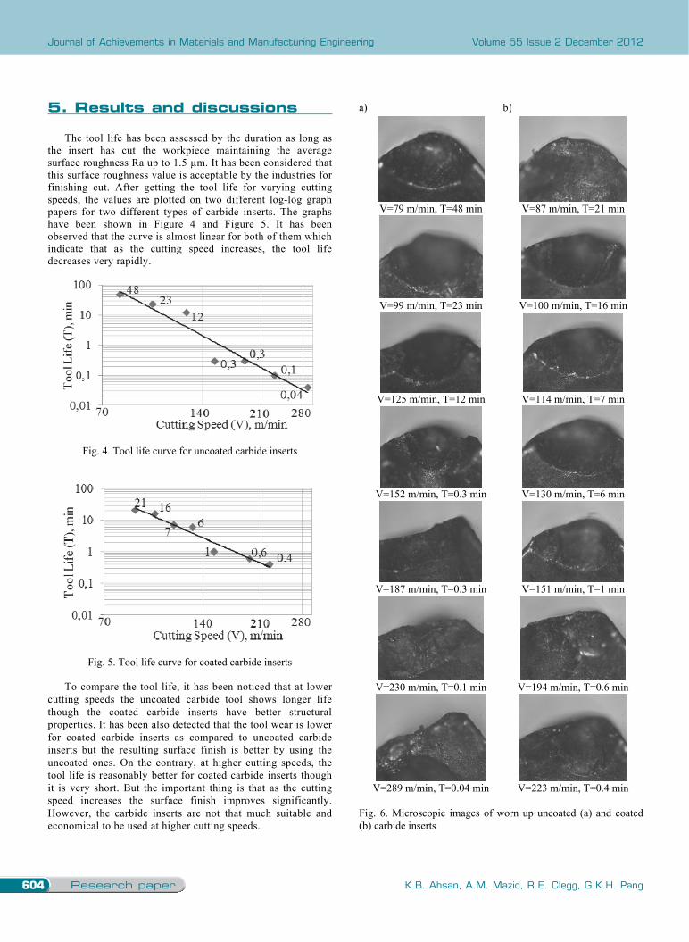
The tool life has been assessed by the duration as long as the insert has cut the workpiece maintaining the average surface roughness Ra up to 1.5 µm. It has been considered that this surface roughness value is acceptable by the industries for finishing cut. After getting the tool life for varying cutting speeds, the values are plotted on two different log-log graph papers for two different types of carbide inserts. The graphs have been shown in Figure 4 and Figure 5. It has been observed that the curve is almost linear for both of them which indicate that as the cutting speed increases, the tool life decreases very rapidly.
Fig. 4. Tool life curve for uncoated carbide inserts
Fig. 5. Tool life curve for coated carbide inserts
To compare the tool life, it has been noticed that at lower cutting speeds the uncoated carbide tool shows longer life though the coated carbide inserts have better structural properties. It has been also detected that the tool wear is lower for coated carbide inserts as compared to uncoated carbide inserts but the resulting surface finish is better by using the uncoated ones. On the contrary, at higher cutting speeds, the tool life is reasonably better for coated carbide inserts though it is very short. But the important thing is that as the cutting speed increases the surface finish improves significantly. However, the carbide inserts are not that much suitable and economical to be used at higher cutting speeds.
a) b)
V=79 m/min, T=48 min V=87 m/min, T=21 min
V=99 m/min, T=23 min V=100 m/min, T=16 min
V=125 m/min, T=12 min V=114 m/min, T=7 min
V=152 m/min, T=0.3 min V=130 m/min, T=6 min
V=187 m/min, T=0.3 min V=151 m/min, T=1 min
V=230 m/min, T=0.1 min V=194 m/min, T=0.6 min
V=289 m/min, T=0.04 min V=223 m/min, T=0.4 min
Fig. 6. Microscopic images of worn up uncoated (a) and coated (b) carbide inserts
5. results and discussions
To understand the tool wear, the microscopic images have been revealed that at lower cutting speeds, the inserts have a self-sharpening tendency which results better surface finish after machining some time. Initially crater wear has been observed on the tool tip and after machining a certain period of time the flank wear has been noticed. Sometimes chipping has been noticed after machining longer period at lower cutting speeds but it is very common at higher cutting speeds. When the tool tip is completely worn up the surface starts to deteriorate rapidly. Deposition of parent material on tool tip and the built-up-edge have been noticed as well. The microscopic images of the worn up inserts for varying cutting speeds have been recorded as in Figure 6.
The temperatures raised during the machining process have been also monitored by an infrared thermal imaging camera. But, as mentioned earlier, the problem is that the camera can measure the surface temperature only and as the machining has been performed with a cutting fluid, it cannot measure the exact temperature of the cutting zone under the cutting fluid. The maximum temperature recorded was 212°C during the machining with higher cutting speed, but it is not supposed to be the right temperature of the cutting zone. However, it has been noticed that the chips started to burn at higher cutting speed and so the actual temperature should be much higher than the recorded ones. Besides the camera cannot capture the thermal image instantly and it takes some time to process. Hence it has been difficult to save the required images as the temperature does not stay long at any point. In Figure 7 two sample thermal images have been depicted. a)
b)
Fig. 7. Sample thermal images at V=125 m/min (a) and V=230 m/min (b) respectively
At higher cutting speed, due to high friction, high temperature is generated which results to burn the chips produced. In this stage it has been postulated that some chemical reactions have been taken place at the tool tip and the newly formed compounds are adhered with the chips as well as the tool tip. In Figure 8 the burning of the chips are clearly revealed.
Fig. 8. Burning of chips due to high temperature generation
6. Conclusions
Machining of Ti-6Al-4V is still difficult as they have some unusual properties which make the machining process more complicated. Here in this research two different types of carbide inserts have been used with varying cutting speeds to understand the effect of cutting speed on tool life. The findings of the investigation can be concluded as follows: 1) Cutting speed is no doubt a significant factor in assessing the
tool life and it is true for both of coated and uncoated carbide inserts. As the cutting speed increases, the tool life decreases very sharply.
2) At lower cutting speeds, the uncoated carbide tool life is better in comparison with the tool life of coated ones while machining by using cutting fluid. As the uncoated carbide tools are cheaper, it will be more economical to use them at lower speed values.
3) The carbide inserts have a self-sharpening tendency at lower speeds which is more significant in uncoated carbide tools. Consequently, the surface finish improves after machining a while.
4) As the cutting speed increases, the surface roughness value (Ra) decreases gradually. Hence for better surface finish, higher cutting speeds are recommended but it will shorten the tool life.
5) Tool life is highly dependent on the application of proper cutting fluid. If the flow of cutting fluid is stopped, the tool fails very shortly. Hence wet machining is safer as compared with the dry machining and it is more sustainable.
6) Though the coated carbide inserts last comparatively longer than the uncoated ones, it is not economical to use any of the carbide inserts at high cutting speed. The tool life may be acceptable up to cutting speed approximately 130 m/min. Hence it is not recommended to use carbide inserts any speed higher than that value.

605
Analysis and modelling
Study on carbide cutting tool life using various cutting speeds for alfa-ß Ti-alloy machining
5. Results and discussions
The tool life has been assessed by the duration as long as the insert has cut the workpiece maintaining the average surface roughness Ra up to 1.5 µm. It has been considered that this surface roughness value is acceptable by the industries for finishing cut. After getting the tool life for varying cutting speeds, the values are plotted on two different log-log graph papers for two different types of carbide inserts. The graphs have been shown in Figure 4 and Figure 5. It has been observed that the curve is almost linear for both of them which indicate that as the cutting speed increases, the tool life decreases very rapidly.
Fig. 4. Tool life curve for uncoated carbide inserts
Fig. 5. Tool life curve for coated carbide inserts
To compare the tool life, it has been noticed that at lower cutting speeds the uncoated carbide tool shows longer life though the coated carbide inserts have better structural properties. It has been also detected that the tool wear is lower for coated carbide inserts as compared to uncoated carbide inserts but the resulting surface finish is better by using the uncoated ones. On the contrary, at higher cutting speeds, the tool life is reasonably better for coated carbide inserts though it is very short. But the important thing is that as the cutting speed increases the surface finish improves significantly. However, the carbide inserts are not that much suitable and economical to be used at higher cutting speeds.
a) b)
V=79 m/min, T=48 min V=87 m/min, T=21 min
V=99 m/min, T=23 min V=100 m/min, T=16 min
V=125 m/min, T=12 min V=114 m/min, T=7 min
V=152 m/min, T=0.3 min V=130 m/min, T=6 min
V=187 m/min, T=0.3 min V=151 m/min, T=1 min
V=230 m/min, T=0.1 min V=194 m/min, T=0.6 min
V=289 m/min, T=0.04 min V=223 m/min, T=0.4 min
Fig. 6. Microscopic images of worn up uncoated (a) and coated (b) carbide inserts
To understand the tool wear, the microscopic images have been revealed that at lower cutting speeds, the inserts have a self-sharpening tendency which results better surface finish after machining some time. Initially crater wear has been observed on the tool tip and after machining a certain period of time the flank wear has been noticed. Sometimes chipping has been noticed after machining longer period at lower cutting speeds but it is very common at higher cutting speeds. When the tool tip is completely worn up the surface starts to deteriorate rapidly. Deposition of parent material on tool tip and the built-up-edge have been noticed as well. The microscopic images of the worn up inserts for varying cutting speeds have been recorded as in Figure 6.
The temperatures raised during the machining process have been also monitored by an infrared thermal imaging camera. But, as mentioned earlier, the problem is that the camera can measure the surface temperature only and as the machining has been performed with a cutting fluid, it cannot measure the exact temperature of the cutting zone under the cutting fluid. The maximum temperature recorded was 212°C during the machining with higher cutting speed, but it is not supposed to be the right temperature of the cutting zone. However, it has been noticed that the chips started to burn at higher cutting speed and so the actual temperature should be much higher than the recorded ones. Besides the camera cannot capture the thermal image instantly and it takes some time to process. Hence it has been difficult to save the required images as the temperature does not stay long at any point. In Figure 7 two sample thermal images have been depicted. a)
b)
Fig. 7. Sample thermal images at V=125 m/min (a) and V=230 m/min (b) respectively
At higher cutting speed, due to high friction, high temperature is generated which results to burn the chips produced. In this stage it has been postulated that some chemical reactions have been taken place at the tool tip and the newly formed compounds are adhered with the chips as well as the tool tip. In Figure 8 the burning of the chips are clearly revealed.
Fig. 8. Burning of chips due to high temperature generation
6. Conclusions
Machining of Ti-6Al-4V is still difficult as they have some unusual properties which make the machining process more complicated. Here in this research two different types of carbide inserts have been used with varying cutting speeds to understand the effect of cutting speed on tool life. The findings of the investigation can be concluded as follows: 1) Cutting speed is no doubt a significant factor in assessing the
tool life and it is true for both of coated and uncoated carbide inserts. As the cutting speed increases, the tool life decreases very sharply.
2) At lower cutting speeds, the uncoated carbide tool life is better in comparison with the tool life of coated ones while machining by using cutting fluid. As the uncoated carbide tools are cheaper, it will be more economical to use them at lower speed values.
3) The carbide inserts have a self-sharpening tendency at lower speeds which is more significant in uncoated carbide tools. Consequently, the surface finish improves after machining a while.
4) As the cutting speed increases, the surface roughness value (Ra) decreases gradually. Hence for better surface finish, higher cutting speeds are recommended but it will shorten the tool life.
5) Tool life is highly dependent on the application of proper cutting fluid. If the flow of cutting fluid is stopped, the tool fails very shortly. Hence wet machining is safer as compared with the dry machining and it is more sustainable.
6) Though the coated carbide inserts last comparatively longer than the uncoated ones, it is not economical to use any of the carbide inserts at high cutting speed. The tool life may be acceptable up to cutting speed approximately 130 m/min. Hence it is not recommended to use carbide inserts any speed higher than that value.
6. conclusions

Research paper606 READING DIRECT: www.journalamme.org
Journal of Achievements in Materials and Manufacturing Engineering Volume 55 Issue 2 December 2012
7) At higher cutting speed, the chips start to burn and the breakage of tool tip has been observed.
8) From this research it is expected that the effect of cutting speed on carbide tool life will be highly beneficial for machining industries especially who produce parts from Ti-alloy. It will also help them to select the right cutting tool for machining this alloy. Eventually this will help to reduce not only the machining time but also the manufacturing cost which will ensure the sustainability in their business.
Acknowledgments
Authors thankfully acknowledge sincere help of Gary Hoare, CQU Workshop and Ewomazino Mike Akpughe, CQU Metrology lab during the experimental investigation. References [1] A.R. Machado, J. Wallbank, Machining of titanium and its
alloys - a review, Proceedings of the Institution of Mechanical Engineers, Part B, Journal of Engineering Manufacture 204 (1990) 53-60.
[2] S. Kalpanjian, Manufacturing engineering and technology, Addison-Wesley Publishing Company, 1995.
[3] T. Childs, K. Maekawa, T. Obikawa, Y. Yamane, Metal machining theory and applications, Arnold, 2000.
[4] C.H. Che-Haron, Tool life and surface integrity in turning Titanium alloy, Journal of Materials Processing Technology 118 (2001) 231-237.
[5] N. Elmagrabi, C.H. Che Hassan, A.G. Jaharah, F.M. Shuaeib, High speed milling of Ti-6Al-4V using coated carbide tools, European Journal of Scientific Research 22/2 (2008) 153-162.
[6] T.L. Ginta, A.K.M.N. Amin, H.C.D.M. Radzi, M.A. Lajis, Tool life prediction by response surface methodology in end milling titanium alloy Ti-6Al-4V using uncoated WC-Co inserts, European Journal of Scientific Research 28/4 (2009) 533-541.
[7] I.A. Choudhury, M.A. El-Baradie, Tool-life prediction model by design of experiments for turning high strength steel (290 BHN), Journal of Materials Processing Technology 77 (1998) 319-326.
[8] T. Özel, Y. Karpat, Predictive modeling of surface roughness and tool wear in hard turning using regression
and neural networks, International Journal of Machine Tools and Manufacture 45 (2005) 467-479.
[9] T. Özel, Y. Karpat, L. Figueira, J.P. Davim, Modelling of surface finish and tool flank wear in turning of AISI D2 steel with ceramic wiper inserts, Journal of Materials Processing Technology 189 (2007) 192-198.
[10] C.X.J. Feng, X. Wang, Development of empirical models for surface roughness prediction in finish turning, The International Journal of Advanced Manufacturing Technology 20 (2002) 348-356.
[11] K. Aslantas, I. Ucun, A. Çicek, Tool life and wear mechanism of coated and uncoated Al2O3/TiCN mixed ceramic tools in turning hardened alloy steel, Wear 274-275 (2012) 442-451.
[12] C.H. Che-Haron, A. Ginting, J.H. Goh, Wear of coated and uncoated carbides in turning tool steel, Journal of Materials Processing Technology 116 (2001) 49-54.
[13] S.H.I. Jaffery, P.T. Mativenga,. Wear mechanisms analysis for turning Ti-6Al-4V-towards the development of suitable tool coatings, International Journal of Advanced Manufacturing Technology 58 (2012) 479-493.
[14] S.K. Choudhury, I.V.K.A. Rao, Optimization of cutting parameters for maximizing tool life, International Journal of Machine Tools and Manufacture 39 (1999) 343-353.
[15] M. Seeman, G Ganesan, R. Karthikeyan, A. Velayudham, Study on tool wear and surface roughness in machining of particulate aluminum metal matrix composite-response surface methodology approach, International Journal of Advanced Manufacturing Technology 48 (2010) 613-624.
[16] M.J. Bermingham, J. Kirsch, S. Sun, S. Palanisamy, M.S. Dargusch,. New observations on tool life, cutting forces and chip morphology in cryogenic machining Ti-6Al-4V, International Journal of Machine Tools and Manufacture 51 (2011) 500-511.
[17] M. Dhananchezian, M.P. Kumar, Cryogenic turning of the Ti-6Al-4V alloy with modified cutting tool inserts, Cryogenics 51 (2011) 34-40.
[18] K.V.B.S.K. Kumar, S.K. Choudhury, Investigation of tool wear and cutting force in cryogenic machining using design of experiments, Journal of Materials Processing Technology 203 (2008) 95-101.
[19] K.A. Venugopal, S. Paul, A.B. Chattopadhyay, Growth of tool wear in turning of Ti-6Al-4V alloy under cryogenic cooling, Wear 262 (2007) 1071-1078.
[20] K.A. Venugopal, S. Paul, A.B. Chattopadhyay, Tool wear in cryogenic turning of Ti-6Al-4V alloy, Cryogenics 47 (2007) 12-18.
references
Acknowledgements