
Senior Thesis Covers - Pennsylvania State · PDF fileSenior Thesis Spring, 2008 ... The second...
54
Senior Thesis Spring, 2008 330 Fellowship Road A Liberty Property Group Project J. Springer Wahl 5 th Year Construction Management Student Professor Riley Faculty Advisor
Transcript of Senior Thesis Covers - Pennsylvania State · PDF fileSenior Thesis Spring, 2008 ... The second...
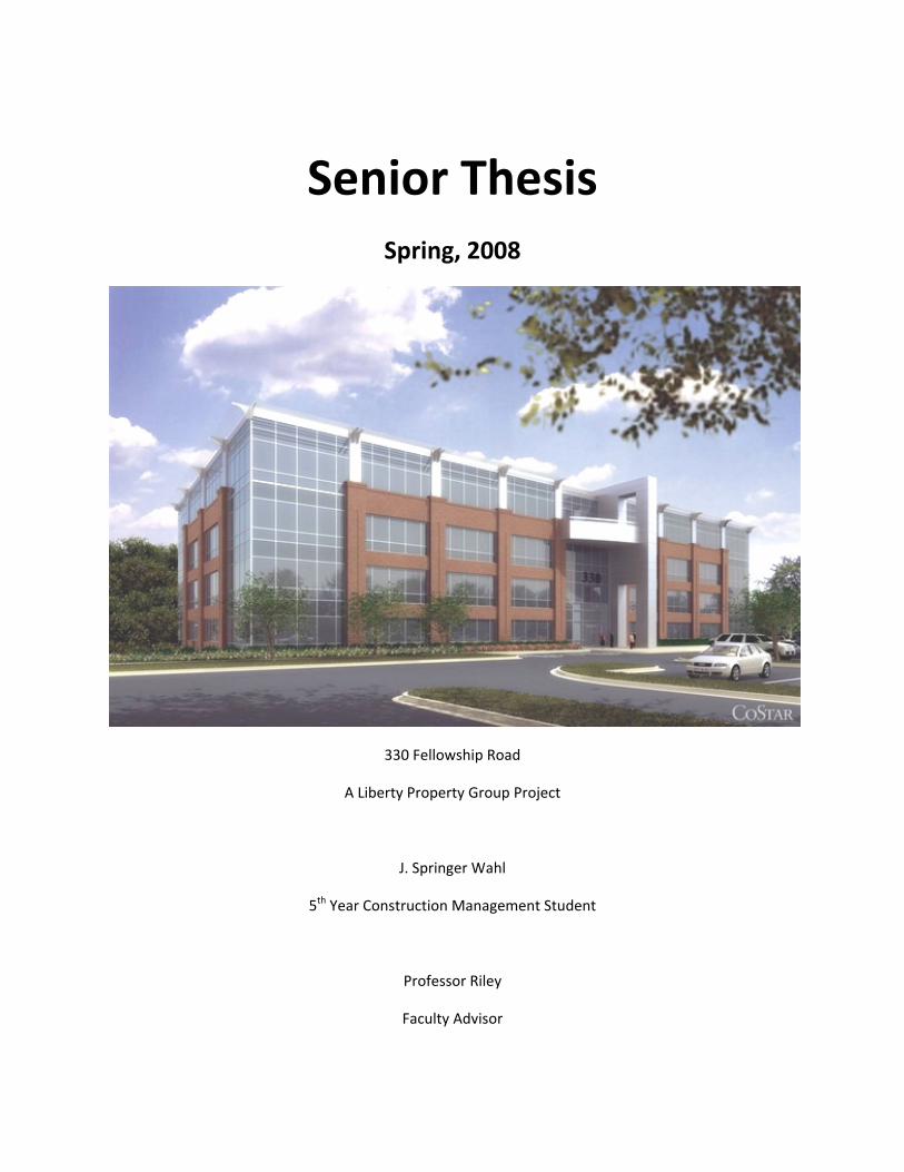
Senior Thesis Spring, 2008
330 Fellowship Road
A Liberty Property Group Project
J. Springer Wahl
5th Year Construction Management Student
Professor Riley
Faculty Advisor
Springer Wahl, 5th Year C.M. 330 Fellowship Road
April 8th, 2008
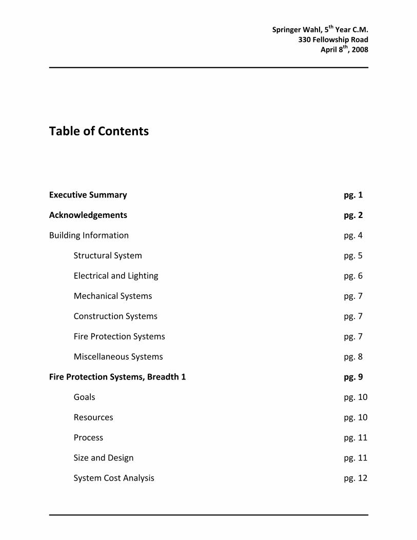
Table of Contents
Executive Summary pg. 1
Acknowledgements pg. 2
Building Information pg. 4
Structural System pg. 5
Electrical and Lighting pg. 6
Mechanical Systems pg. 7
Construction Systems pg. 7
Fire Protection Systems pg. 7
Miscellaneous Systems pg. 8
Fire Protection Systems, Breadth 1 pg. 9
Goals pg. 10
Resources pg. 10
Process pg. 11
Size and Design pg. 11
System Cost Analysis pg. 12

Springer Wahl, 5th Year C.M. 330 Fellowship Road
April 8th, 2008
Controlling Factors pg. 13
Thermal Model pg. 14
Thermal Calculations pg. 15
Conclusions pg. 16
Further Research pg. 17
Solar Panel Designs, Breadth 2 pg. 19
Goals pg. 20
Resources pg. 20
Process pg. 20
Solar Panel Sizings pg. 21
Government Subsidies pg. 22
Value of System pg. 23
Conclusions pg. 23
Mass Solar Panel Implementation, Depth pg. 26
Goals pg. 26
Resources pg. 26
Process pg. 27
New Jersey Savings pg. 27
Downfalls pg. 28
Power Purchase Agreements pg. 29
Springer Wahl, 5th Year C.M. 330 Fellowship Road
April 8th, 2008
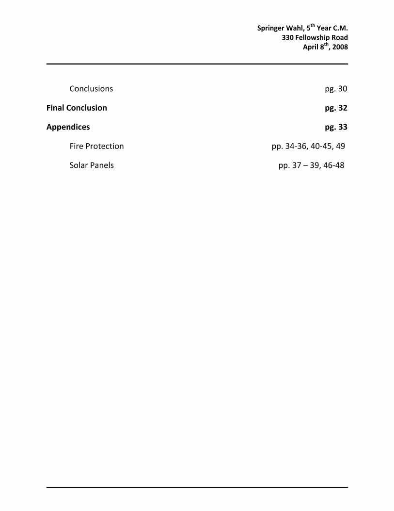
Conclusions pg. 30
Final Conclusion pg. 32
Appendices pg. 33
Fire Protection pp. 34‐36, 40‐45, 49
Solar Panels pp. 37 – 39, 46‐48
Springer Wahl, 5th Year C.M. 330 Fellowship Road
April 8th, 2008
1
Executive Summary
Within these pages you will find the research and findings of my 5th year
Construction Management Thesis. One of the first pages to be found will be a page
acknowledging and thanking all those that helped me to find answers and design new
systems.
The second part of this Thesis report is a brief description of the project which the
research is based around. 330 Fellowship Road is a 4 story 100,000 square feet core and
shell office building in Southern New Jersey.
Following that will be the sections containing the research and innovation. First
will be a new Fire Protection Systems method that aims to further steel structural
integrity in a fire. Next will be a section that describes how the owner of the building
stands to make a lot of money by using government incentives and Solar Panel Systems.
Lastly, is a research topic that discusses how to apply the Solar Panel ideas over a
quantity of buildings a General Contractor is building, or that a Property Trust company
owns. The most important thing to note is a deviation from the second version of the
Proposal. The old depth topic research wasn’t very interesting, and there wasn’t that
much money to be saved. With the new depth topic research, the owner stands to save
millions of dollars in a single state alone.
Springer Wahl, 5th Year C.M. 330 Fellowship Road
April 8th, 2008
2
Acknowledgements
The first people I’d like to thank are my fellow students. Not only for making the
time here immensely enjoyable, but for sharing knowledge and ideas in fields I had not
studied. I can only hope that I earned that honor by doing the same for them.
Specifically, I would like to name a few students who helped me directly with my
research. First is Maxwell Chien who helped to get my fire protection systems research
heading in a viable direction. Next to thank would be William Tang, who helped us to
figure out specifics of the equations needed to calculate total heat loss. Professor
Bahnfleth then helped me to sum up the vast amount of information I had on the system
to a useable and desirable solution. And last to thank for the fire protection research is
Professor Hargather who initially pointed me in the correct direction for the beginnings
of my research.
For my Solar Power research, I’d like to begin to thank Tom Yost and Kyle
Macht who are both members of the PSU Solar Decathlon team. They helped me to start
the Solar Panel sizing and placement. Next would be David Kanida who not only helped
me to figure out the power properties of solar panels, but some of the government
benefits available in purchasing a system.
Next I would like to thank Liberty Property Trust, and specifically Jim Sunday
VP and Jenny Schow. They allowed me to use their building for research. They also

Springer Wahl, 5th Year C.M. 330 Fellowship Road
April 8th, 2008
3
helped to send me information I needed. I hope my research and work can help benefit
them and Liberty Property Trust greatly.
Lastly I’d like to thank my Father, especially for all the money I promise I will
pay back in some form or another. But mostly for all the funny stories and life
experiences that kept me going both in happiness, and knowledge I had gained.
Springer Wahl, 5th Year C.M. 330 Fellowship Road
April 8th, 2008
4
Project Information
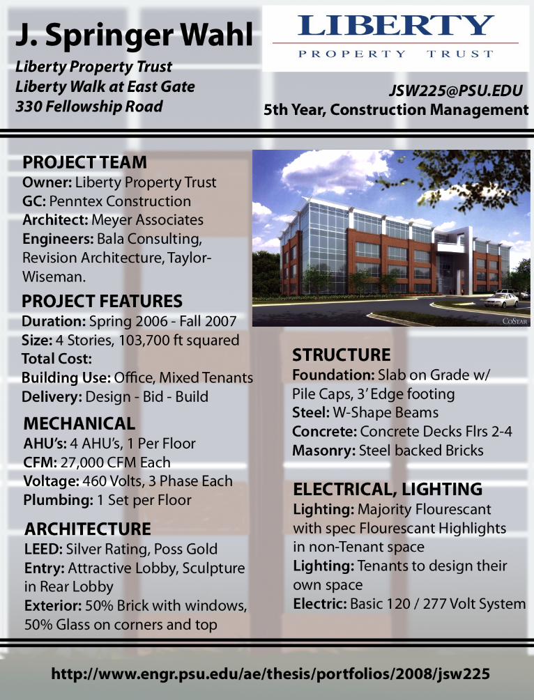
330 Fellowship Road is a part of a four building complex that is Liberty Walk at
East Gate in Mount Laurel, New Jersey. Liberty Properties have purchased a corner of a
street block containing 3 buildings. Two buildings were demolished and three were built,
including 330 Fellowship Road. There are a pair of warehouses behind 330 Fellowship
Road that hope to soon purchase and replace. All of the land will be enhanced, including
miles of sidewalk for the general public to use.
There were two buildings that needed to be demolished before construction could
commence. This helped to earn points in the Leed rating. How extensive of demolition
that would be needed is unknown.
This building is a typical shell and core Office Building coming in at a little more
than 25,000 square feet per floor, for four floors. The 239ft by 114ft rectangular building
has both new and old architectural features, as well as some very interesting ideas. It will
be receiving at least Leed Silver rating, with a chance of receiving a Leed Gold rating.
For roughly 3/4 of the front and rear exteriors length wise and for 3 floors up the
building has attractive brick with details and raised texture sections. Above the 3/4
lengths and on the 4th floor it switches from brick to sandblasted aluminum, as well as
making the windows larger. However, on 1/8 of the front and rear exteriors on the ends,
there is no brick or aluminum, but pure spandrel and vision glass from the ground to the
top of the 4th floor. A similar effect is produced for the two shorter sides except for a
Springer Wahl, 5th Year C.M. 330 Fellowship Road
April 8th, 2008
5
little more than 1/4 the short side length on each end being glass. It has a very elegant
entrance lobby, with perhaps an even more interesting back lobby which connects and
split the bottom floor down the middle. On the north side of the lobby, there is an atrium
which the second floor balcony looks over.
The curtain wall system isn’t too complex. Where there are bricks, they shall be
laid in front of a structural steel backer wall with a minimum 1” air gap. An exterior
vapor barrier as well as a sheathing layer will be placed on the outside of the steel backer
wall. The interior face of the panel will be insulated. The glass will be glazed with the
frames having a Duraner XL Finish. The vision glass will be 1” thick, with another layer
of 1/4" Low-E glass.
The roof will be an energy star roof for Leed Points. It will be a thermoplastic
polyolefin (TPO) roof of a reinforced 0.60 mm thickness, on top of 6” rigid insulation.
This insulation will be adhered to the metal decking, and not pierced. This system will
provide an R value of 30.
Structural
The structural system is a pretty basic or common system. It has a 4” Slab on
Grade Foundation, with concrete edge beams around the perimeter of the building. The
bottoms of the edge beams need to be a minimum of 3’ below grade. Below the interior
steel columns are 2’ to 4’ deep from top of SOG square column footings.
Springer Wahl, 5th Year C.M. 330 Fellowship Road
April 8th, 2008
6
Running up from the foundation are all W12 steel columns, with weights ranging
from 45 to 79 with the larger columns being on the interior grid. W18x35’s are the most
common beam size, being placed where the tenants would lease. Slightly smaller beams
are used for the interior third span, being that it is smaller. The girders on the end of the
building as well as the interior longitudinal girders are bigger, from sizes W21x50 to
W24x84. This description is typical for the two other floors above. For the roof, much
smaller beams are used, as well as trusses, with the 28K6 being the most common truss.
Electrical and Lighting
The system is a standard 277 volt / 480Y volt building. The entire building is on
a 2000 Amp Service. The Air Handling Units run off of the 480 volt service. Because
the tenant space is designed to be self furnished and finished, the electricity service is not
finished. There is a 250 KW generator Life Safety Standby in an exterior weather proof
casing.
The only finished lighting resides in the two lobbies, and any common areas
including elevator lobbies, and a single corridor on the second floor. The majority of the
lights in most of the common space are recessed circular fluorescent lamps. The corridor
has square 2x2 fluorescent lamps. The sculpture in the rear lobby is backlit by 10 single
line fluorescent bulbs.
Springer Wahl, 5th Year C.M. 330 Fellowship Road
April 8th, 2008
7
Mechanical System
There is a specific Air Handling Unit per floor, with the ducts running down the
chases to each floor directly down from each AHU. Because the tenant space isn’t
leased, the final diffusers or finished ducts aren’t in place yet. The tenant will place these
when it leases the space. The cooling operation runs off of electricity, while the heating
coils run off of a gas line in from the street.
Construction Systems
There is a General Contractor from Penntex Construction running the show. I
currently do not have the information of what kind of contracts were signed between the
owner and GC, and the GC and subcontractors. The building will be LEED Rated, with
the most probable rating of Silver. If Liberty Properties works hard enough, they’ll
receive a Gold rating. Liberty was proud to boast of their support for the GBC and the
LEED system, telling the workers that what they are doing will be good for the
environment. Liberty hopes that this will result in more productive workers as they take
more pride in their work.
Fire Protection Systems
The Fire Protection is a standard system sized for Ordinary Danger Levels. It
stems directly off of a 12” water main from the street into the building. The main feeder
rises up to each floor and branches off to cover all of the floor area. It is a standard wet
system. All of the interior exposed columns have fire proofing sprayed on.

Springer Wahl, 5th Year C.M. 330 Fellowship Road
April 8th, 2008
8
Miscellaneous Systems
The Elevator is an Otis Holed Hydraulic LVM 3500, with a 3500 pound rated
capacity each. The telecommunications system is not currently finished, due to the tenant
space not being finished. The tenants will run the lines from the electrical rooms to
where they want.
Springer Wahl, 5th Year C.M. 330 Fellowship Road
April 8th, 2008
9
Problem Statement – Fire Protection
Breadth Number One
There is no real problem in the current state of Fire Protection Systems. In
general, water comes in from the water main, and runs to a Sprinkler Specific water
pump. This pump needs to be able to send the correct water pressure to the furthest area
from the pump. Basically it needs to adequately supply the point in a far corner of the
building. Along the way fluid dynamics rob the flowing water of energy by friction and
pressure loss.
In current buildings, the sprinklers go up a central core, or at least up a logical
area of the building. From here, the lines are branched off to cover the each story’s floor
area.
While there is no major problem plaguing this industry, this didn’t stop my desire
to make it better. On 9/11 the attacks did something that no one had predicted would
happen. They blasted off the fire protection material on the columns. With the
subsequent fires, this exposed the columns, which had very little heat resistance
capability, directly to the fires. It took very little time for the columns to hit failure
temperature where the loss of strength became more than the safety factors applied to the
loading of the columns.
The solutions to our problems only go as far as our imaginations take us, or as far
as our failures have fallen.
Springer Wahl, 5th Year C.M. 330 Fellowship Road
April 8th, 2008
10
Goals
The utmost goal of this was to reroute the sprinkler lines through any building and
to use the sprinkler lines themselves as heat sinks on the columns. Instead of running the
sprinkler in one giant line up a central core, and then branching off at each floor, I would
run the lines up the columns. In the event of a fire, the running water would remove heat
from the column, and then run out the sprinkler heads, further extinguishing, quenching
or delaying the damaging effects.
But this new system won’t come without a price. It was expected that it would
cost more, and that the schedule ramifications would be greatly more than the current
simple installations.
Resources
1.) Penn State Course IHS 420, Fire Protection Systems.
2.) Michael Hargather, Me 201 Professor
3.) William Bahnfleth, AE Department Professor
4.) Maxwell Chien, AE Undergraduate Student
5.) William Tang, AE Undergraduate Student
6.) Fundamentals of Heat and Mass Transfer, DEWITT, ICROPERA
7.) ASHRAE Standards Water Tables
Springer Wahl, 5th Year C.M. 330 Fellowship Road
April 8th, 2008
11
Process
1.) Size and design the new system
2.) Estimate new system’s costs
3.) Estimate old system’s costs
4.) Analyze Controlling factors
5.) Set up Thermal Model
6.) Get help to analyze Thermal Model
7.) Conclusions
8.) Further Research
Size and Design
First off, all of the columns are assumed to be W12x79 sized throughout the
building. There will be 4 sprinkler pipes which rise up each column. At first, there were
several problems with the design of the system. Namely, I had figured on each rising line
being dedicated to only one floor. This created a problem where at the top of each
sprinkler riser, a complex system of turns, bends and breaks to cover the required floor
area for the sprinklers themselves.
This created another problem, however it might not be as bad as the problem
stated immediately above. By dedicating a single pipe to each floor, as the pipes break
off and end, the column would lose that pipe’s cooling capacities as it doesn’t follow the

Springer Wahl, 5th Year C.M. 330 Fellowship Road
April 8th, 2008
12
column up. This isn’t so terrible considering that the bottom floor column piece has the
greatest capacity for failure in comparison to the higher floors, however it would create
uneven cooling / heating problems on those top floors.
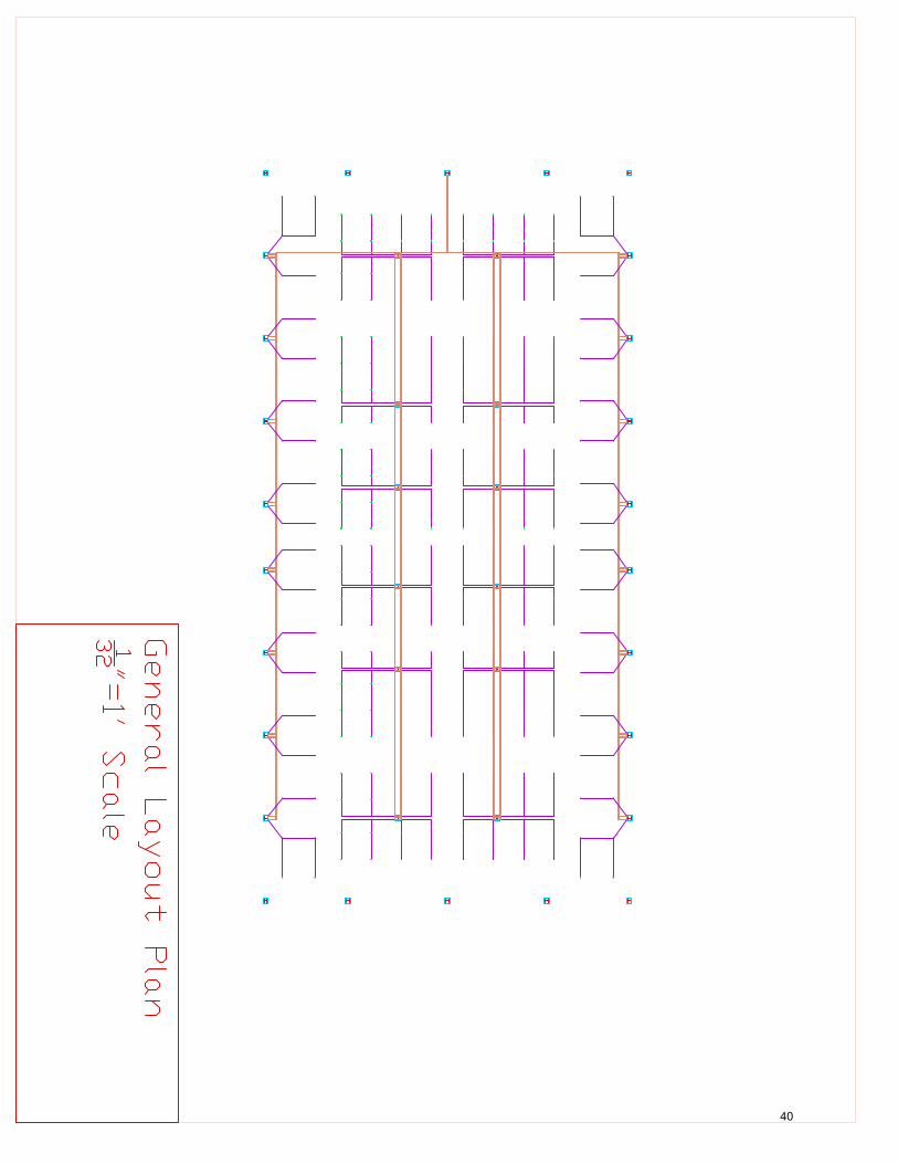
After a little day dreaming in a Thermal Dynamics class, the solution became
quite apparent to the complex bends and uneven cooling problems. Instead of having a
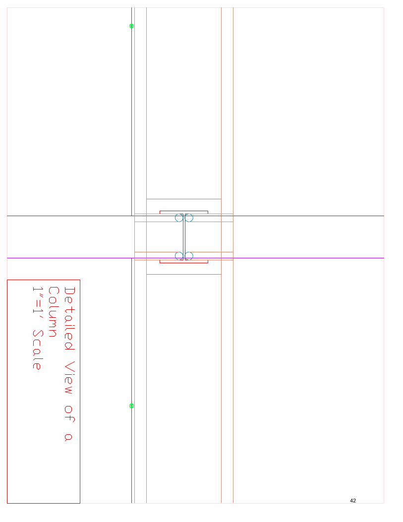
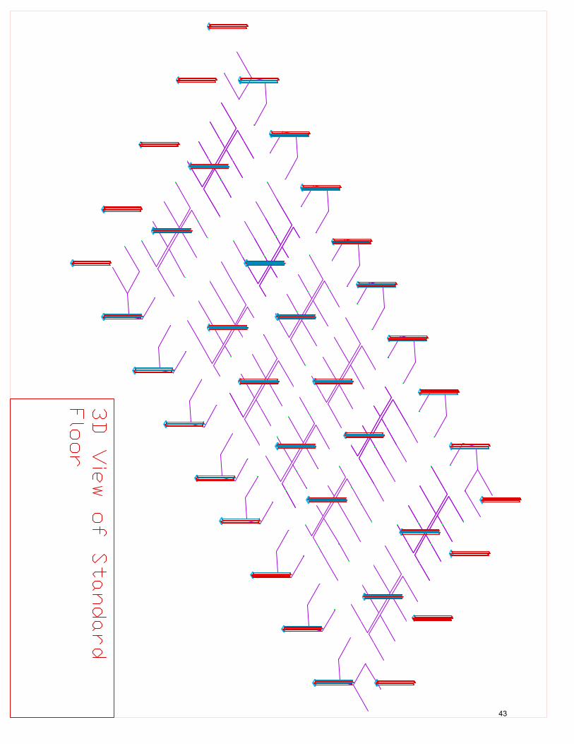
dedicated line per floor, all the pipes would hit all of the floors. From each pipe at each
floor would emanate an “F” shaped layout having roughly 4 sprinkler heads each as seen
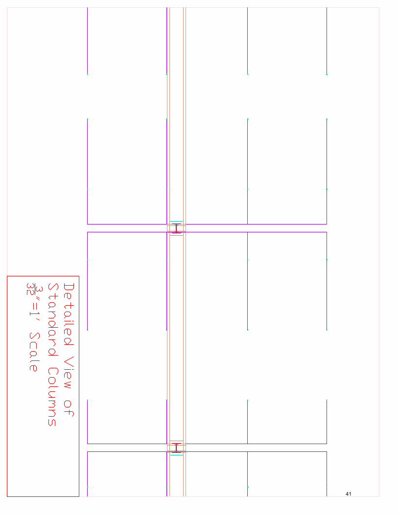
on Appendix Page 39, General Layout Plan. On Appendix Page 40 is a more detailed
look at a single column system. On Appendix Page 41 is a detailed view of the column,
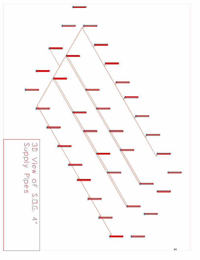
the pipes, and the baseplate. On Appendix Pages 42-43 are 3d views of the standard
system per floor, and the underslab feeders respectively.
The amount of water in the system is sized hydraulically as per learned in IHS
420 class on Fire Protection. It was assumed that one column’s system would be
running, and no more. From the building being Ordinary Hazard, roughly 12.5 Gallons
per minute would flow through each sprinkler. With the sprinkler lines being sized to be
2”, there is very little pressure loss. All told, per “F” shape, there runs 50 Gallons per
minute. So a single column with all sprinklers firing will be consuming near 200 Gallons
per minute. With losses from pipe travel and pressure losses, the entire Sprinkler Pump
will be sized at 250 Gallons per minute.
System Cost Analysis
Springer Wahl, 5th Year C.M. 330 Fellowship Road
April 8th, 2008
13
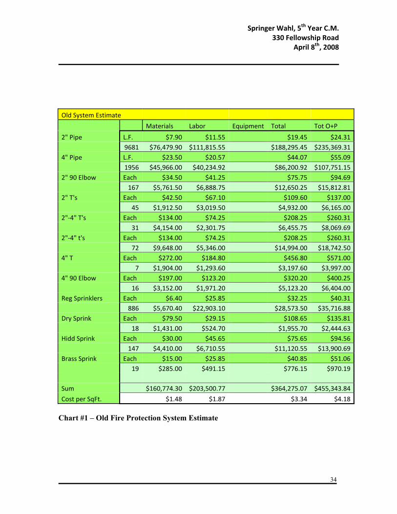
A detailed breakdown of the costs is located in Appendix Pages 33 and 34. The
current system is estimated to cost roughly $450,000 with a square foot cost of $4.18 for
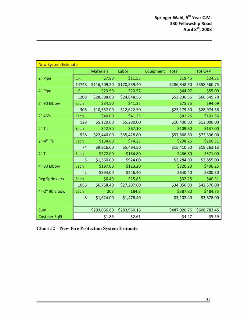
the old system. The new system is estimated to cost roughly $610,000 with a square foot
cost of $5.59 for the new system. There is an explicit cost difference of $153,439.61,
which translates to my new system costing roughly 34% more.
There could be several reasons for the cost disparity. First, there is much more 2”
pipe in my new system, but some of the costs are saved up due to the lack of as many 4”
sprinkler mains that don’t need to be run through the building. In general, there are more
connection pieces in the new system, which also drives up the cost.
However, that being said I believe my new system is much more conducive to
prefabrication construction practices, especially on some of the larger highrises.
Considering highrises further, the repeatability could also help to drive down the price
more.
Controlling Factors
The first controlling factor analyzed was the actual loading upon the column. The
column including K factors and length is rated for 900 Kips. Through using 1.6L + 1.2D
loading for the roof including 20lbs LL, 20lbs Snow, and 20lbs Dead, and using given
loadings for interior floors of each beam, the calculated load the bottom column is
carrying is 617 Kips.
Springer Wahl, 5th Year C.M. 330 Fellowship Road
April 8th, 2008
14
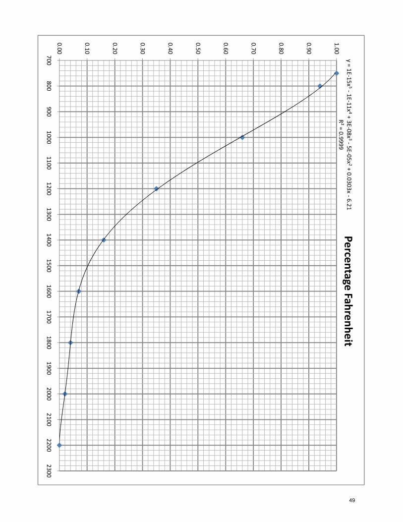
Dividing this by the 900 Kips rated, it loses the leeway the safety factors grant it
at 68.5% strength. Through graphing this is seen on Appendix Page 48 which comes
from an 8-value strength vs. temperature chart shown in the Steel Manual, the
corresponding temperature to a strength percentage of 68.5 is roughly 980 degrees
Fahrenheit. This basically means that when the column heats up to 980 degrees, it will
begin to fail assuming that the building is fully loaded.
However, upon conferring with several Mechanical Options like Mr. Chien, Mr.
Tang and Professor Bahnfleth, we have decided that the real controlling factor would be
the water in the pipes attached to the column flashing over to steam. This is a big
problem because not only does the water in the pipes remove heat from the column, but
they still act as the fire quenching agent from the sprinkler heads. If the water becomes
steam, then the building is doubly in trouble.
Thermal Model
Given that I am very lacking in thermal dynamic capabilities, the model that
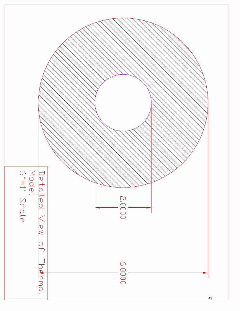
would be set up needed to be very basic. The basics of it would be the W12x79 Wide
Flanged column would be compressed into a pipe with very thick walls.
This pipe is based around being 2” wide. From here, I looked up the area of the
W12x79 column, and decided the thickness. The resulting pipe’s wall would be roughly
2” thick, making the entire column stand 6” wide as documented on Appendix Page 44.
Springer Wahl, 5th Year C.M. 330 Fellowship Road
April 8th, 2008
15
The water flow in this simulated column will only be 50 GPM to simulate the
kind of flow that will exist in the new system. Making the flow higher like to the 200
GPM that will be flowing past the actual column could create fluid dynamics problems in
such a small pipe.
Thermal Calculations
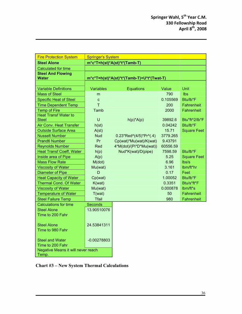
The basis of the thermal calculations is a lumped capacitance thermal analysis.
The amount of heat the steel can absorb will be equal to the amount of heat given off
when it is surrounded by air of a certain temperature multiplied by time. The heat given
off by the air is controlled by the convective heat transfer coefficient of the air (the ease
of which it gives off energy) multiplied by the surface area of the outside column, then
multiplied by the temperature of the air minus the temperature goal of the equation. This
first part assumes that no water is flowing. It is a basic calculation to figure out how long
the steel will take to get to a failure temperature. This is documented both for 200
degrees water failure and 980 degrees material failure of just the steel alone in Appendix
Page 35.
The second calculation is very similar to the first. But in addition to the heat
added to the steel from the surrounding temperature, the amount of heat subtracted is also
calculated from the flowing water. First, the conductive heat transfer coefficient needs to
be calculated from the amount of heat the flowing water can remove, then this is
Springer Wahl, 5th Year C.M. 330 Fellowship Road
April 8th, 2008
16
multiplied by the inner surface area of the pipe, and then by the temperature of the water
minus the temperature goal of the equation. This is all documented in Appendix Page 35.
The conductive heat transfer coefficient is not so easy to calculate. First I needed
to calculate the Prandtl number which deals with heat capacity, the viscosity and the
thermal conductivity of water. Then I calculated the Reynolds number, which deals with
the mass flow rate, the surface area per unit length of the pipe, and the viscosity. From
there, I use the Prandtl number and the Reynolds number to calculate the Nusselt number.
Then the conductive heat coefficient can be calculated using that number, the thermal
conductivity of water and the diameter of the pipe.
The results of these calculations are documented in Appendix Page 35.
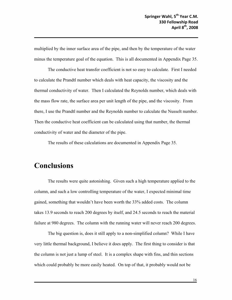
Conclusions
The results were quite astonishing. Given such a high temperature applied to the
column, and such a low controlling temperature of the water, I expected minimal time
gained, something that wouldn’t have been worth the 33% added costs. The column
takes 13.9 seconds to reach 200 degrees by itself, and 24.5 seconds to reach the material
failure at 980 degrees. The column with the running water will never reach 200 degrees.
The big question is, does it still apply to a non-simplified column? While I have
very little thermal background, I believe it does apply. The first thing to consider is that
the column is not just a lump of steel. It is a complex shape with fins, and thin sections
which could probably be more easily heated. On top of that, it probably would not be

Springer Wahl, 5th Year C.M. 330 Fellowship Road
April 8th, 2008
17
heated in a steady state. Meaning that it probably won’t be uniformly heated, so some
sections of the column will be a different temperature.
However, given all that you also need to remember that there will be 3x more
water flow (200 GPM) rushing past the column than the calculated 50 GPM. The only
stipulation for this is that the sprinkler pipes would need to get a good thermal bond with
the column. Some sort of material would need to be chosen to fill up all of the spaces to
the column, possibly including around the pipes as well.
Further Research
This is a very promising system. I am naming it the Springer System. It will
need more research done to determine if it truly is a viable system.
First and foremost, this needs to get in the hands of a Mechanical Engineer, or a
Mechanical Systems Option AE. From this a more detailed analysis will be able to be
performed, either by hand or in some sort of computer program. This would need to be
done on a Wide Flange shaped column. Included in that analysis would need to be a
temperature gradient drawing of the column. However, given that the 50 degree water
would stop the lumped column from heating to 200 degrees, I don’t believe that on the W
shape that any small piece or any piece large enough would reach the material failure
temperature. According to the information taken from the steel manual, the steel starts to
lose strength at 750 degrees Fahrenheit.
Springer Wahl, 5th Year C.M. 330 Fellowship Road
April 8th, 2008
18
Past any calculations, I believe it’s too risky to put in a building without some sort
of mock up test. Given a limited application across the building industry, it could be
years or possibly even decades or longer until the off chance that the Springer System’s
full capabilities are tested. But it would be extremely expensive to just light a bunch of
full scale mockups on fire. Professor Hargather was studying how to apply small scale
mockups to real world buildings using explosives. I believe that something very similar
could be done using my system. If we know how a regular column reacts in a fire, we
can set several small different scales of a similar construction, copy the scales and
construction and use flowing water, and try to find some factors at which it could be
applied to a real world size building.
Springer Wahl, 5th Year C.M. 330 Fellowship Road
April 8th, 2008
19
Solar System Designs
Breadth Number Two
With emerging technologies, a Solar Panel system is becoming an increasingly
better choice for businesses and building owners. The increasing efficiencies have driven
up the power that is able to be converted from the Sun’s energy, at the same time driven
down the power it takes to produce a solar panel. These panels take 1 to 4 years to earn
back the energy it took to create them, but still have life expectancy of roughly 30 years.
The problems exist with the cost of these solar panels. While over the lifetime of
the solar panels they can earn their money back, it is often a difficult expenditure for any
owner, as will be described later. However, it is possible to take advantage of
government rebates and incentives at a federal, state and local level to decrease the cost
of the system to very manageable levels.
Many companies are now starting up solely for the purpose of taking advantage of
the government subsidies. These companies would put on a solar panel system on a
building at no cost to the owner, and then begin to sell power back to the owner at a
better than standard rate. After 15-20 years, the owner assumes control and ownership of
the system and can generate their own power.

Springer Wahl, 5th Year C.M. 330 Fellowship Road
April 8th, 2008
20
Goals
The main goal of this research will be to generate a plan and a system for the
current owner to immediately use and implement. I will detail the costs of a new system,
as well as give quoted schedule estimates. Further, I will show how these systems are
financially viable and well worth the initial costs, given the current subsidies market.
Resources
1.) Dsireusa.org Detailing government subsidies
2.) Solar Power in Building Design: The engineer’s complete design resource,
GEVORKIAN
3.) Sun Power Corporation
4.) Tom Yost, Undergrad AE, Solar Decathlon Member
5.) Kyle Macht, Undergrad AE, Solar Decathlon Member
6.) The Heat Shed, Sun Power Corp dealer
7.) David Kanida, PE, IDA Inc.
Process
1.) Research Weather Data
2.) Pick solar panel
3.) Place solar panels on roof
Springer Wahl, 5th Year C.M. 330 Fellowship Road
April 8th, 2008
21
4.) Calculate power generated
5.) Calculate costs and benefits
6.) Show payback periods with and without benefits
Solar Panel Sizings
The first step I did was to use NASA’s meteorological website to find the
Insolation from the sun in south New Jersey. The average insolation over a 10 year
period per year is 4.35 kWhrs/m^2/day at the optimum angle of 33 degrees. This is the
average energy the sun generates per square meter of surface area.
After some brief research on the internet, Sun Power Corporations 305 Watt
model was chosen. This panel is roughly 3 feet by 5 feet. After some trigonometry, if
the panel was laid with the 5’ length on the bottom, it would stand 1.65’ tall at the
highside, and would need 2.5’ behind it for the shadow to clear it. Just to give it more
room, each panel and a decent amount of walking room behind it would take up a 5’ by
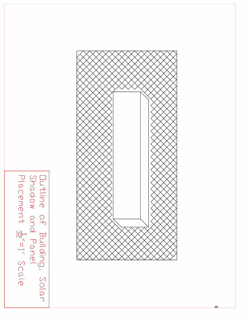
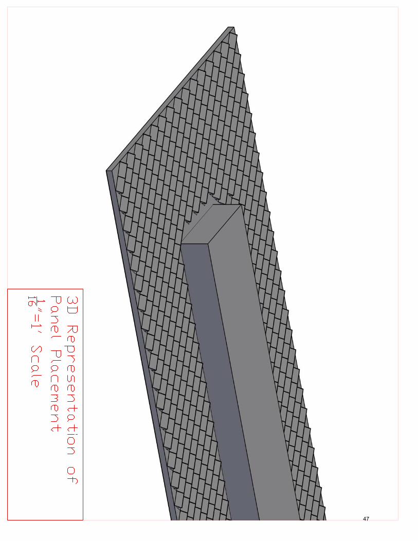
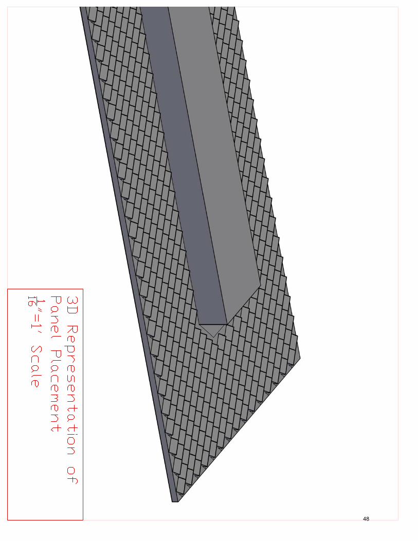
5’ horizontal box, as documented in Appendix Page 45. With south being nearly at a 45
degree angle to the building lengthwise, it was very easy to arrange the panels. However,
the mechanical roof housing is given some leeway to keep the solar panels that would
nearly always be shaded further away. With all of this being taken into consideration,
681 panels could be placed on the roof. This is shown on Appendix Pages 46 and 47.
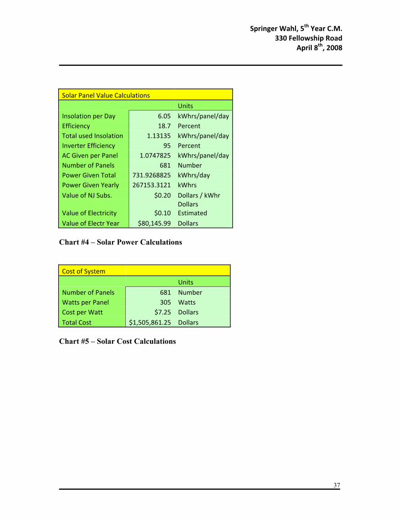
The size of the panel is 15 square feet. This is 1.39 square meters. This
multiplied by the insolation yields about 6.05 kWhrs/day. Sun Power Corp’s 305 Watt
Springer Wahl, 5th Year C.M. 330 Fellowship Road
April 8th, 2008
22
model is currently the top of the line panel. It has an efficiency of 18.7%. This means
that of the 6.05kWhrs/day provided, the panels can only give 1.13kWhrs/day. With Sun
Power Corp’s top inverter conversion rate of 95%, this gives off 1.074kWhrs/day per
panel of AC power, and back into the system.
With 681 panels, this gives off 731.5kWhrs/day for this building. Over a year, the
power generated is about 267MWhrs. This is documented on Appendix Page 36, Chart
#4.
Government Subsidies
As per the Dsireusa.org website, there are two major subsidies currently active in
New Jersey. The first is at the Federal level where 30% of the system’s cost can be
written off as a tax credit. Combined with this, 30% of the depreciated value can be
written off every year as well as a tax credit. This gives a savings of roughly 60% per
system, provided the system is still in place. Every year the program gets extended by
one year, so it is not a sure thing.
The other major subsidy is from the State of New Jersey. New Jersey is offering
$0.20 per kWhr produced. This is very substantial. The estimated value of electricity for
330 Fellowship Road building is about $0.10 per kWhr.
Springer Wahl, 5th Year C.M. 330 Fellowship Road
April 8th, 2008
23
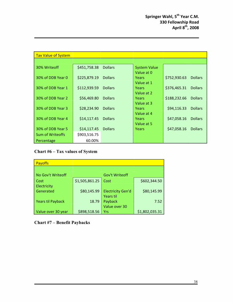
Value of System
The value of this system is very substantial, with and without the government tax
credits. This is documented expressly in Appendix Page 37, Chart #7. At an estimated
$7.25 per watt cost quoted from The Heat Shed of the 305 system, the total cost of the
system is about $1,500,000. The energy generated by the solar panels valued at $0.10
electricity cost plus $0.20 NJ Incentive is worth $80,000 a year. Assuming no inflation
or different dollar values over the years, this system will be paid back in about 19 years
without any of the Government tax credits. After that, the system will save the owner
$900,000 over the remaining 11 years of the estimated 30 year lifespan. This is shown on
Appendix Page 37, Chart #6.
The system saves the owner a significant amount more with the Government tax
credits. The system with the rebates will cost the owner a total of $600,000 over the 5
year depreciations. Again, assuming no inflation or differing dollar values, this system
will be paid back in 7.5 years. The system will save the owner $1,800,000 over the
remaining 22.5 year lifespan. This is shown on Appendix Page 37, Chart #6.
Conclusions
As the time goes on, these systems will only become more efficient. Even
without the Tax Credits, I believe that this system is worth it to install. $600,000 is a
significant amount of money. By the time the solar panels need to be replaced, it should
Springer Wahl, 5th Year C.M. 330 Fellowship Road
April 8th, 2008
24
only be cheaper. Not only that, but with the efficiencies climbing, the systems could cost
half as much, but still produce twice as much. Using that wild unsubstantiated claim, and
assuming no inflation or differing dollar values, the same sized system as shown here
could cost $750,000, but produce $160,000 worth of electricity every year.
But if you could guarantee the Government incentives, or act fast enough to
ensure you’ll receive this year’s incentives, there is very little risk in building a system.
With a decent amount of money to be gained from building a solar panel system, the only
thing you are really risking is whether or not you will earn more by taking advantage of
government programs.
Another consideration is that a controlling factor for a smaller company may not
be the cost or speed of construction of the systems, but the amount of taxes paid each
year. It would do a company no good to claim more in tax credits a year than they pay,
especially with the year by year tax credit program extensions.
A decent problem I encountered when picking my solar system is that I
accidentally picked the best system out there. While it is nice to show the best that the
building can currently host, it has been made apparent that it might not be feasible. With
Sun Power Corporation’s panels being the best and given their non-infinite production
capabilities, the demand for their product is extremely high. As such, Sun Power Corp
gets to pick and choose which buildings or projects will house their panels. Unless you
are a friend of theirs, or have a really interesting project, you probably won’t get to use
their panels. If there was more time, the systems would be redesigned to use a more
available, but still good set of solar panels.
Springer Wahl, 5th Year C.M. 330 Fellowship Road
April 8th, 2008
25
There was a problem encountered way late in my research of this solar panel
system. After talking to the owner of The Heat Shed, I made casual mention of the angle
of the solar panels to get the most insolation over the year. They are currently set at 33
degrees. However, the owner of The Heat shed he mentioned that nearly all of the raised
angles are 15 degrees. If they are raised any further they will catch too much wind and
become a problem to handle. The solar panels will lose 4-5% of the insolation by
dropping the angle nearly by half. However, because of the trigonometry involved, this
may be able to be reclaimed from having the panels closer together. Unfortunately, there
is not enough time to calculate the power lost and then the number of panels gained.
Springer Wahl, 5th Year C.M. 330 Fellowship Road
April 8th, 2008
26
Applying Solar Systems on a Mass Scale
Depth Research
With the money to be gained from purchasing a solar panel system these days,
there are very few reasons left for nearly all builders or all owners to invest in a system of
some sort. With every passing year the benefits become greater due to the research of the
Photovoltaic systems.
Goals
The main goal of my depth research is to convince all new building owners to
include a solar panel system with every building capable. Another goal is to convince
every property trust company that leases out office spaces that it is profitable to start
retrofitting older buildings with new solar systems where the government incentives
make it worthy.
Resources
1.) Dsireusa.org Detailing government subsidies
2.) Solar Power in Building Design: The engineer’s complete design resource,
GEVORKIAN
3.) Sun Power Corporation
Springer Wahl, 5th Year C.M. 330 Fellowship Road
April 8th, 2008
27
4.) Tom Yost, Undergrad AE, Solar Decathlon Member
5.) Kyle Macht, Undergrad AE, Solar Decathlon Member
6.) The Heat Shed, Sun Power Corp dealer
7.) David Kanida, PE, IDA Inc.
Process
1.) Use Second Breadth Topic for Data
2.) Calculate NJ Savings for Liberty Property Trust
3.) Describe Power Purchase Agreements
4.) Design Sample PPA for Liberty Buildings
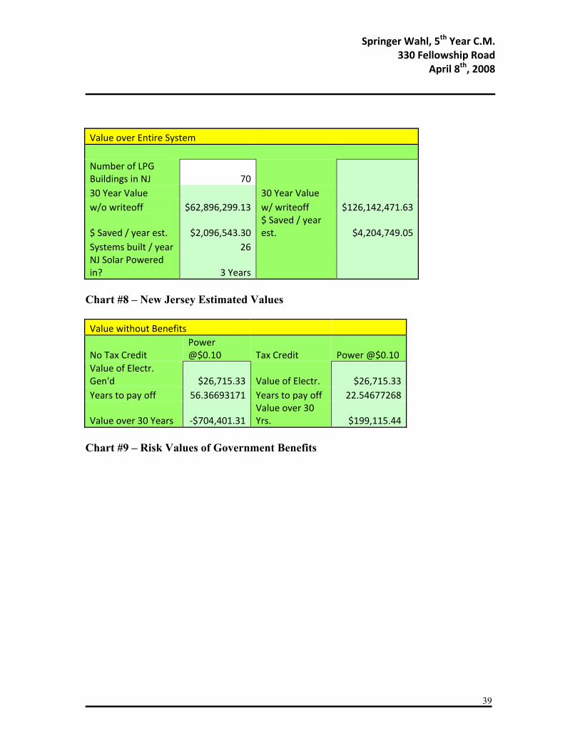
Liberty Property New Jersey Savings
The savings for just 330 Fellowship Road building with the government tax
credits is $1.8 million. This is a significant amount of money. However, there are 69
other Liberty Property Trust buildings in New Jersey. Given that New Jersey has some
powerful incentives, combined with the tax credits, there should be no reason to not outfit
as many buildings as possible.
For example, over the 70 buildings, the amount of savings (assuming everything
above holds true) over the 30 year lifespan of the panels is $126 million. This is making
Springer Wahl, 5th Year C.M. 330 Fellowship Road
April 8th, 2008
28
a few assumptions. The first assumption is that all these buildings would magically be
built instantly. As per the time quoted to me from The Heat Shed, with the repeatability
present with Liberty, it would take roughly 2 weeks to outfit each building. This gives us
26 buildings outfitted a year.
The next major assumption is that each building is roughly the same size as 330
Fellowship Road, or at least has the same amount of useable space to mount solar panels.
A rough estimate of 330 Fellowship Road has 680 Panels over about 17,000 square feet.
While the building may be bigger or smaller than 330 Fellowships 103,000 square feet
over 4 floors, as long as it has 17,000 square feet of roof space it will produce similar
amounts of energy.
Downfalls
Unfortunately, given the current efficiency and cost of available Solar Panels, it is
not fiscally viable to use Solar Panels given no government incentives. Using the
information from the Solar Panel sizing, with only $0.10 per kWhr saved from electricity
usage and no tax credits, it would take 56.5 years to cover the costs of the solar power
system. With this the owner would lose $700,000 over the course of the 30 years for
each building, and then the cost of a new system at the 30 year life span mark, assuming
the owner would buy another.
With the tax credit only, and no production incentives, the system would be paid
off in 22.5 years, and save the owner $200,000 over the remaining 7.5 years.
Springer Wahl, 5th Year C.M. 330 Fellowship Road
April 8th, 2008
29
But, there are many claims about costs per watt on the horizon that are truly
outstanding. For example, a company named Nanosolar claims to be able to make solar
panels at $0.99 a watt. These panels aren’t really panels either, but super thin plates of
conductors mounted on a paper like substance. This could allow the panels to be
mounted in more places than just an array on the roof, thus allowing more electricity to
be produced.
They claim to be able to give us solar panels at an ultimate of one tenth to one
fifth the prices. At one fifth the price, this would make the current system cost roughly
$300,000. However, they are currently only producing about half the energy of the most
efficient panel which I have quoted above, making the value of energy provided roughly
$14,000 with no government incentives. With all of these assumptions, this system could
be paid off by itself in 22 years with another $115,000 saved over the remaining 8 years.
Power Purchase Agreements
All of the above was geared to the owner of the building being the one who would
place the system. However, a lot of buildings are built by General Contractors. Because
of this, if the incentives are right the General Contractors should take advantage of
putting into place a Power Purchase Agreement.
For example, say the GC instituted a Power Purchase Agreement over a lease
period of 20 years in the prime conditions of New Jersey. Using the information
calculated in Breadth 2, the GC can make a million dollars over 20 years before
Springer Wahl, 5th Year C.M. 330 Fellowship Road
April 8th, 2008
30
transferring ownership to the building owner. The GC can make more if the PPA lease
lasts longer. With developments promised for the future, a lifespan for solar cells of 40
years may be possible, thus increasing the time useable for a PPA.
However, the prime conditions may not exist elsewhere like they do in NJ.
Assuming that the federal tax credits are in place, a GC could hope to make $200,000
over the course of 30 years. This itself may not be worth the investment given the short
term risk that the tax credits may be revoked every year. But if the GC can clear the 5
year risk, then it should be attempted.
Conclusions
With the current state of affairs of Photovoltaic cells and systems, it is a difficult
decision whether or not to invest in some instances. In 10 years with the new
technologies it may be much easier to choose.
For a property holdings company like Liberty Property Trust, there are a few
instances where they should install a solar system. The first and most obvious instance is
when both the tax credit system and a local production incentive exist. With this, same
assumptions standing, a company could make $1.8 million in straight savings. With no
tax credits, the company could save $800,000. With no production incentive, but a tax
credit present, the property trust company stands to save $200,000 which is still a
significant amount. With no benefits however, the companies stand to lose a lot of
money currently by investing in a system.
Springer Wahl, 5th Year C.M. 330 Fellowship Road
April 8th, 2008
31
It is a little bit different for a General Contractor, but not by much. Given all the
incentives, it is still clearly worth it for the GC to place a PPA on the table. With just a
20 year lease, they stand to make a million dollars or more in profit. However with no
tax credits available, a GC stands to only make $97,000 in profit over 20 years. This
might be difficult to achieve, given that very few states have strong production
incentives. But it may be worth the endeavor if the GC can rig several buildings in
advantageous states every year. $100,000 could be worth a lot over many buildings.
Considering the opposite with a production incentive present, but no tax credits, the
payback period is 19 years. While it is possible to extend the lease to 25 years, it
wouldn’t be attractive to a client for them to assume control on the remaining 5 years of
the panels’ lives. However, if the GC can convince the client, they would stand to make
$500,000 per building. With no benefits at all, it is not viable to set up a PPA.
In a University environment much like Penn State, a lot of the same plans apply
from the property trusts. However, this is contingent on Penn State paying federal taxes.
With the lack of production incentives in Pennsylvania, without the federal taxes being
paid, a solar panel system on the buildings would not be worth it. But with the great
fundraising abilities of PSU, they may be able to supplement the tax credit loss (assuming
that it is a loss) with donations from Alumni. Instead of applying the systems to the
buildings, they could be placed in unused fields that PSU does own.
Springer Wahl, 5th Year C.M. 330 Fellowship Road
April 8th, 2008
32
Final Conclusions
After much research and deliberation I cannot be unbiased when I recommend my
new Fire Protection System. Of course it seems like it is the greatest thing ever to me. It
should increase structural safety and prevent any collapse due to temperature loading.
But is the extra cost estimated at 30-40% more worth something that rarely ever happens?
Even with a bias, I think it needs to be scale modeled to determine actual effects.
As for the solar systems, given the right conditions there is no fiscal reason that
any building owner should not follow the plan set out in this thesis. The same applies to
most current buildings in the planning stages or not too far along in the building process.
The propensity to profit with something so easy to do should make all companies
consider adding these to their projects.
Springer Wahl, 5th Year C.M. 330 Fellowship Road
April 8th, 2008
33
Appendices, Calculations, and Charts
Springer Wahl, 5th Year C.M. 330 Fellowship Road
April 8th, 2008
34
Old System Estimate
Materials Labor Equipment Total Tot O+P
2" Pipe L.F. $7.90 $11.55 $19.45 $24.31 9681 $76,479.90 $111,815.55 $188,295.45 $235,369.314" Pipe L.F. $23.50 $20.57 $44.07 $55.09 1956 $45,966.00 $40,234.92 $86,200.92 $107,751.152" 90 Elbow Each $34.50 $41.25 $75.75 $94.69 167 $5,761.50 $6,888.75 $12,650.25 $15,812.812" T's Each $42.50 $67.10 $109.60 $137.00 45 $1,912.50 $3,019.50 $4,932.00 $6,165.002"‐4" T's Each $134.00 $74.25 $208.25 $260.31 31 $4,154.00 $2,301.75 $6,455.75 $8,069.692"‐4" t's Each $134.00 $74.25 $208.25 $260.31 72 $9,648.00 $5,346.00 $14,994.00 $18,742.504" T Each $272.00 $184.80 $456.80 $571.00 7 $1,904.00 $1,293.60 $3,197.60 $3,997.004" 90 Elbow Each $197.00 $123.20 $320.20 $400.25 16 $3,152.00 $1,971.20 $5,123.20 $6,404.00Reg Sprinklers Each $6.40 $25.85 $32.25 $40.31 886 $5,670.40 $22,903.10 $28,573.50 $35,716.88Dry Sprink Each $79.50 $29.15 $108.65 $135.81 18 $1,431.00 $524.70 $1,955.70 $2,444.63Hidd Sprink Each $30.00 $45.65 $75.65 $94.56 147 $4,410.00 $6,710.55 $11,120.55 $13,900.69Brass Sprink Each $15.00 $25.85 $40.85 $51.06 19 $285.00 $491.15 $776.15 $970.19 Sum $160,774.30 $203,500.77 $364,275.07 $455,343.84
Cost per SqFt. $1.48 $1.87 $3.34 $4.18 Chart #1 – Old Fire Protection System Estimate
Springer Wahl, 5th Year C.M. 330 Fellowship Road
April 8th, 2008
35
New System Estimate
Materials Labor Equipment Total Tot O+P
2" Pipe L.F. $7.90 $11.55 $19.45 $24.31 14748 $116,509.20 $170,339.40 $286,848.60 $358,560.754" Pipe L.F. $23.50 $20.57 $44.07 $55.09 1208 $28,388.00 $24,848.56 $53,236.56 $66,545.702" 90 Elbow Each $34.50 $41.25 $75.75 $94.69 306 $10,557.00 $12,622.50 $23,179.50 $28,974.382" 45's Each $40.00 $41.25 $81.25 $101.56 128 $5,120.00 $5,280.00 $10,400.00 $13,000.002" T's Each $42.50 $67.10 $109.60 $137.00 528 $22,440.00 $35,428.80 $57,868.80 $72,336.002"‐4" T's Each $134.00 $74.25 $208.25 $260.31 74 $9,916.00 $5,494.50 $15,410.50 $19,263.134" T Each $272.00 $184.80 $456.80 $571.00 5 $1,360.00 $924.00 $2,284.00 $2,855.004" 90 Elbow Each $197.00 $123.20 $320.20 $400.25 2 $394.00 $246.40 $640.40 $800.50Reg Sprinklers Each $6.40 $25.85 $32.25 $40.31 1056 $6,758.40 $27,297.60 $34,056.00 $42,570.004"‐2" 90 Elbow Each 203 184.8 $387.80 $484.75 8 $1,624.00 $1,478.40 $3,102.40 $3,878.00 Sum $203,066.60 $283,960.16 $487,026.76 $608,783.45
Cost per SqFt. $1.86 $2.61 $4.47 $5.59 Chart #2 – New Fire Protection System Estimate
Springer Wahl, 5th Year C.M. 330 Fellowship Road
April 8th, 2008
36
Fire Protection System Springer's System Steel Alone m*c*T=h(st)*A(st)*t*(Tamb-T) Calculated for time Steel And Flowing Water m*c*T=h(st)*A(st)*t*(Tamb-T)+U*t*(Twat-T) Variable Definitions Variables Equations Value Unit Mass of Steel m 790 lbs Specific Heat of Steel c 0.105569 Btu/lb*F Time Dependent Temp T 200 Fahrenheit Temp of Fire Tamb 2000 Fahrenheit Heat Transf Water to Steel U h(p)*A(p) 39892.6 Btu*ft^2/lb*FAir Conv. Heat Transfer h(st) 0.04242 Btu/lb*F Outside Surface Area A(st) 15.71 Square FeetNusselt Number Nud 0.23*Red^(4/5)*Pr^(.4) 3779.265 Prandtl Number Pr Cp(wat)*Mu(wat)/K(wat) 9.43791 Reynolds Number Red 4*M(dot)/(Pi*D*Mu(wat)) 60556.59 Heat Transf Coeff, Water h(p) Nud*K(wat)/D(pipe) 7598.59 Btu/lb*F Inside area of Pipe A(p) 5.25 Square FeetMass Flow Rate M(dot) 6.96 lbs/s Viscosity of Water Mu(wat) 3.161 lbm/ft*hr Diameter of Pipe D 0.17 Feet Heat Capacity of Water Cp(wat) 1.00052 Btu/lb*F Thermal Cond. Of Water K(wat) 0.3351 Btu/s*ft*F Viscosity of Water Mu(wat) 0.000878 lbm/ft*s Temperature of Water T(wat) 50 Fahrenheit Steel Failure Temp Tfail 980 Fahrenheit Calculations for time Seconds Steel Alone 13.90510076Time to 200 Fahr Steel Alone 24.53841311Time to 980 Fahr Steel and Water -0.00278803Time to 200 Fahr Negative Means it will never reach Temp.
Chart #3 – New System Thermal Calculations
Springer Wahl, 5th Year C.M. 330 Fellowship Road
April 8th, 2008
37
Solar Panel Value Calculations
Units Insolation per Day 6.05 kWhrs/panel/dayEfficiency 18.7 Percent Total used Insolation 1.13135 kWhrs/panel/dayInverter Efficiency 95 Percent AC Given per Panel 1.0747825 kWhrs/panel/dayNumber of Panels 681 Number Power Given Total 731.9268825 kWhrs/day Power Given Yearly 267153.3121 kWhrs Value of NJ Subs. $0.20 Dollars / kWhr
Value of Electricity $0.10Dollars Estimated
Value of Electr Year $80,145.99 Dollars Chart #4 – Solar Power Calculations Cost of System
Units Number of Panels 681 Number Watts per Panel 305 Watts Cost per Watt $7.25 Dollars Total Cost $1,505,861.25 Dollars
Chart #5 – Solar Cost Calculations
Springer Wahl, 5th Year C.M. 330 Fellowship Road
April 8th, 2008
38
Tax Value of System
30% Writeoff $451,758.38 Dollars System Value
30% of DDB Year 0 $225,879.19 Dollars Value at 0 Years $752,930.63 Dollars
30% of DDB Year 1 $112,939.59 Dollars Value at 1 Years $376,465.31 Dollars
30% of DDB Year 2 $56,469.80 Dollars Value at 2 Years $188,232.66 Dollars
30% of DDB Year 3 $28,234.90 Dollars Value at 3 Years $94,116.33 Dollars
30% of DDB Year 4 $14,117.45 Dollars Value at 4 Years $47,058.16 Dollars
30% of DDB Year 5 $14,117.45 Dollars Value at 5 Years $47,058.16 Dollars
Sum of Writeoffs $903,516.75
Percentage 60.00% Chart #6 – Tax values of System Payoffs
No Gov't Writeoff Gov't Writeoff Cost $1,505,861.25 Cost $602,344.50 Electricity Generated $80,145.99 Electricity Gen'd $80,145.99
Years til Payback 18.79Years til Payback 7.52
Value over 30 year $898,518.56Value over 30 Yrs $1,802,035.31
Chart #7 – Benefit Paybacks
Springer Wahl, 5th Year C.M. 330 Fellowship Road
April 8th, 2008
39
Value over Entire System
Number of LPG Buildings in NJ 70 30 Year Value 30 Year Value w/o writeoff $62,896,299.13 w/ writeoff $126,142,471.63
$ Saved / year est. $2,096,543.30$ Saved / year est. $4,204,749.05
Systems built / year 26 NJ Solar Powered in? 3 Years
Chart #8 – New Jersey Estimated Values Value without Benefits
No Tax Credit Power @$0.10 Tax Credit Power @$0.10
Value of Electr. Gen'd $26,715.33 Value of Electr. $26,715.33Years to pay off 56.36693171 Years to pay off 22.54677268
Value over 30 Years ‐$704,401.31Value over 30 Yrs. $199,115.44
Chart #9 – Risk Values of Government Benefits
40
41
42
43
44
45
46
47
48
y = 1E‐15x5‐1E‐11x
4+ 3E‐08x
3‐5E‐05x
2+ 0.0303x ‐6.21
R² = 0.9999
0.60
0.70
0.80
0.90
1.00
Percentage Fahrenheit
0.00
0.10
0.20
0.30
0.40
0.50
700800
9001000
11001200
13001400
15001600
17001800
19002000
21002200
2300
49