Seismic Vulnerability Study of the Alaskan Way Viaduct: Typical Three-Span Units Marc Eberhard (J....
29
Seismic Vulnerability Study of the Alaskan Way Viaduct: Typical Three-Span Units Marc Eberhard (J. De la Colina, S. Ryter, P. Knaebel) Lacey, Washington
-
Upload
amie-parks -
Category
Documents
-
view
217 -
download
0
Transcript of Seismic Vulnerability Study of the Alaskan Way Viaduct: Typical Three-Span Units Marc Eberhard (J....
Seismic Vulnerability Study of the Alaskan Way Viaduct:
Typical Three-Span Units
Marc Eberhard
(J. De la Colina, S. Ryter, P. Knaebel)
Lacey, Washington
Outline
• Scope of Study• Description of Typical WSDOT-Designed Unit• Analyses of WSDOT Unit
– 3D Response Spectrum– 2D Nonlinear Static
• Vulnerability Assessments of WSDOT Unit– Flexure– Shear– Anchorage– Splices– Joints– Footings
• Comparison of SED and WSDOT Typical Units

Scope of Structural Evaluation
• WSDOT and SED Typical Three-Span Sections
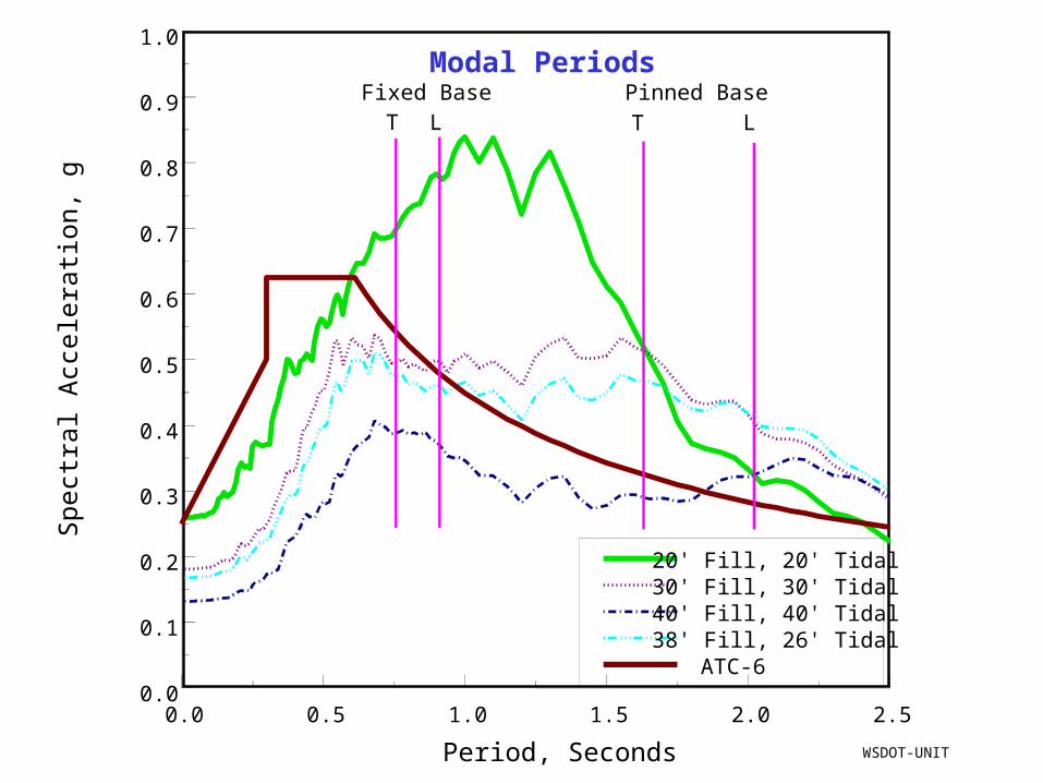
• Ground Motions– ATC-6 spectrum, Type III
soil with Ag = 0.25g– Site-specific spectra for
20-ft fill/20-ft tidal deposit
• Analyses– 3D Response Spectrum
Analysis– Nonlinear 2D Static
Analysis
• ATC-6-2 and Priestley Procedures for:– Flexure– Shear– Anchorage– Splices– Joints– Pile-Supported Footings
• As-Designed Unit (no deterioration or construction errors)
• Retrofit Priorities

Outside Scope
• Failure Modes– Torsion– Effect of anchorage
deficiencies on beam/slab shear capacity
– Effect of splice failure on shear resistance
– Piles– Fracture at welded lap splices– Behavior of square bars
• Procedures Developed Since 1994
• Specific Retrofit Recommendations
• Atypical Sections– North-end and South-end
single-deck structures (Bents 1-53)
– Double-deck to single-deck transition structures (e.g., outrigger bents)
– Ramps– Curve
• Interactions among three-span frames
• Variations in Properties – Material properties– Reinforcement

WSDOT Unit: Longitudinal Elevation
Interior Frame
Interior Frame
Exterior Frame
Exterior Frame

WSDOT Interior Bent: Transverse Elevation
Short Splices
No Top Reinforcement in Footings
Short Beam Bar Anchorage
Little Joint Confinement
Little Column Transverse Reinforcement
No. 3 @ 12 in.

WSDOT Interior Bent: Column Cross-Section
Analyses
• Assumed Material Properties• Description of Typical WSDOT-Designed Unit• Analyses of WSDOT Unit
– 3D Response Spectrum– 2D Nonlinear Static
• Vulnerability Assessments of WSDOT Unit:– Flexure– Shear– Anchorage– Splices– Joints– Footings
• Comparison of SED and WSDOT Typical Units
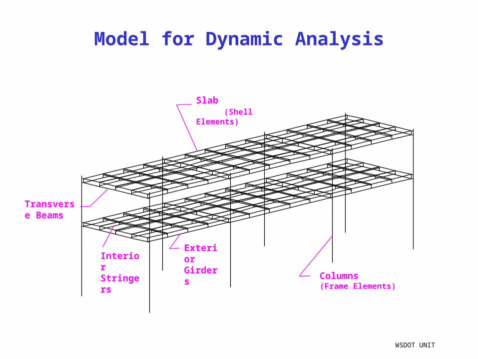
Model for Dynamic Analysis
WSDOT UNIT
Exterior Girders
Transverse Beams
Interior Stringers
Slab (Shell Elements)
Columns (Frame Elements)
0.0 0.5 1.0 1.5 2.0 2.5
Period, Seconds
0.0
0.1
0.2
0.3
0.4
0.5
0.6
0.7
0.8
0.9
1.0
Spe
ctra
l Acc
eler
atio
n, g
20' Fill, 20' Tidal30' Fill, 30' Tidal40' Fill, 40' Tidal38' Fill, 26' TidalATC-6
Modal PeriodsFixed Base
T LPinned Base
T L
WSDOT-UNIT

Summary of Minimum Flexural C/D Ratios
Response Spectra
Direction Rec, First Story
Rec, Second Story
Rec,
Beams, Girders
ATC-6 Transverse 0.36 1.17 0.43
Longitudinal 0.31 0.92 0.75
Site-Specific Transverse 0.22 0.80 -
Longitudinal 0.22 0.59 -
Depending on site and direction, expect first-story column displacement ductility demands in the range of 2-4. Location of max. demands depends on column base-fixity. Low ductility demands in 2nd story, with exception of M+ in some beams.
WSDOT UNIT

WSDOT-INT FRAME
Two-Dimensional, Nonlinear Analysis

Total
One Exterior Frame
One Interior Frame
WSDOT-INT FRAME
Wunit = 4800 kips Vtrans/Wunit = 0.25
Force-Deflection Relationship

WSDOT-INT FRAME
Column Moments

Beam Bending Moment (first level)
WSDOT-INT FRAME
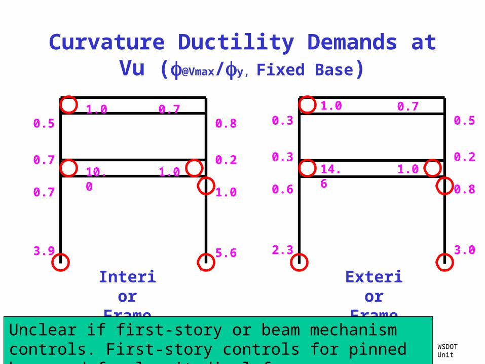
Curvature Ductility Demands at Vu (@Vmax/y, Fixed Base)
Interior Frame
3.9
0.7
0.7
0.5
0.7
1.0
1.010.0
5.6
0.2
0.8
1.0
WSDOT Unit
3.0
0.2
0.5
0.8
1.0
14.6
Exterior Frame
2.3
0.7
0.3
0.3
0.6
1.0
Unclear if first-story or beam mechanism controls. First-story controls for pinned base and for longitudinal frames.
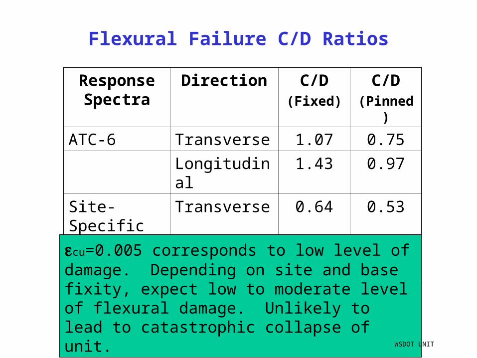
Response Spectra
Direction C/D(Fixed)
C/D(Pinned)
ATC-6 Transverse 1.07 0.75
Longitudinal 1.43 0.97
Site-Specific Transverse 0.64 0.53
Longitudinal 0.89 0.70
cu=0.005 corresponds to low level of damage. Depending on site and base fixity, expect low to moderate level of flexural damage. Unlikely to lead to catastrophic collapse of unit.
WSDOT UNIT
Flexural Failure C/D Ratios

Shear Failure
Vi
Vf
i f
Initial
Final
Displacement Ductility
Case A
Case B
Case C
= 2 = 4
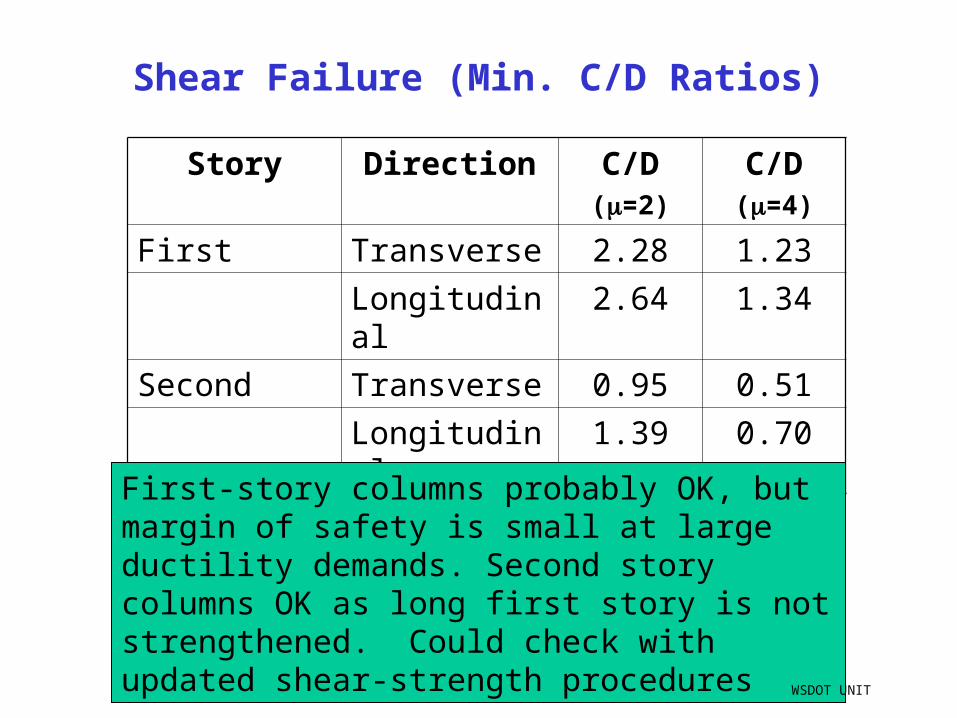
Shear Failure (Min. C/D Ratios)
Story Direction C/D(=2)
C/D(=4)
First Transverse 2.28 1.23
Longitudinal 2.64 1.34
Second Transverse 0.95 0.51
Longitudinal 1.39 0.70
First-story columns probably OK, but margin of safety is small at large ductility demands. Second story columns OK as long first story is not strengthened. Could check with updated shear-strength procedures
WSDOT UNIT
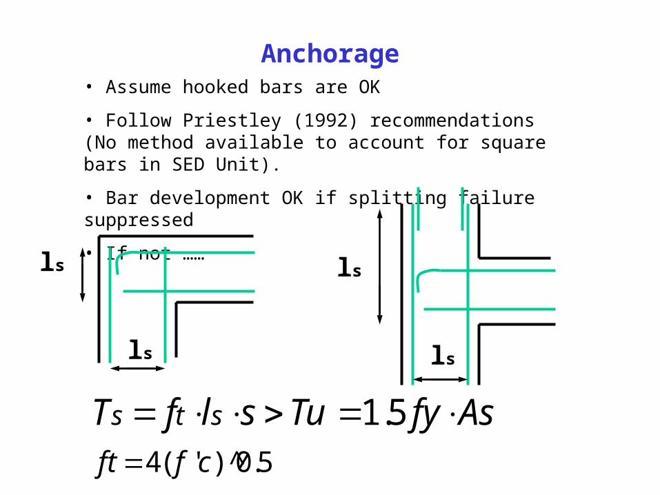
Anchorage
AsfyTuslfT sts 5.1
• Assume hooked bars are OK
• Follow Priestley (1992) recommendations (No method available to account for square bars in SED Unit).
• Bar development OK if splitting failure suppressed
• If not ……
ls
ls
ls
ls
5.0)^'(4 cfft
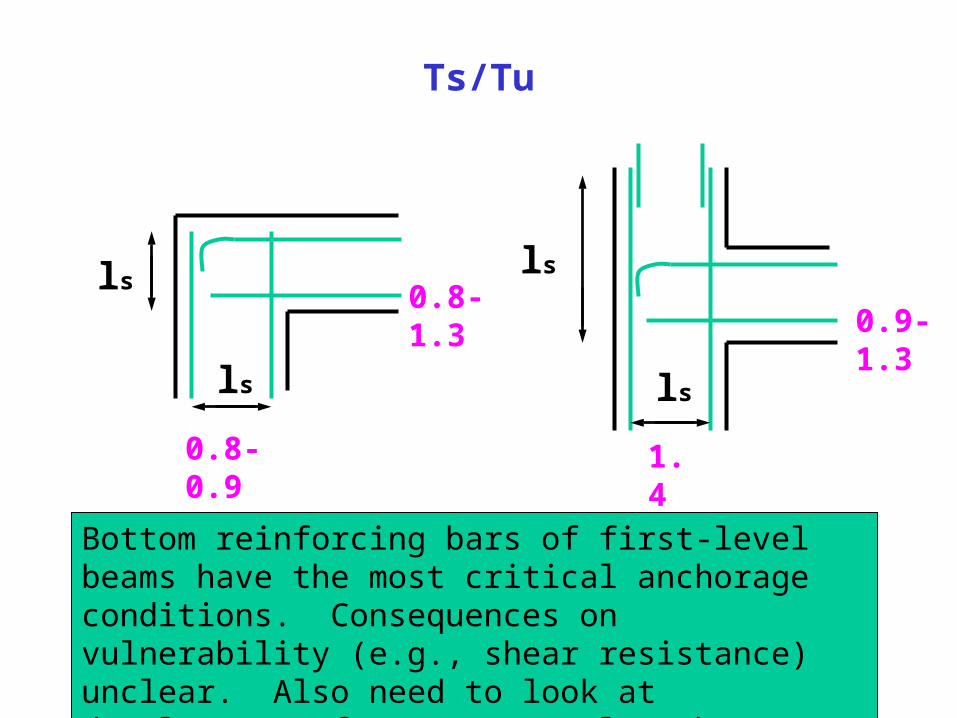
Ts/Tu
ls
ls
ls
ls
0.8-0.9
0.9-1.3
1.4
0.8-1.3
Bottom reinforcing bars of first-level beams have the most critical anchorage conditions. Consequences on vulnerability (e.g., shear resistance) unclear. Also need to look at development of top-story column bars through joint.
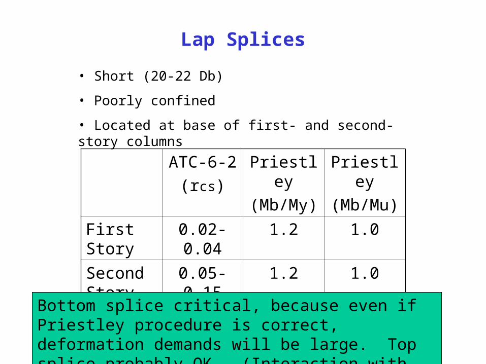
Lap Splices
ATC-6-2
(rcs)
Priestley
(Mb/My)
Priestley
(Mb/Mu)
First Story 0.02-0.04 1.2 1.0
Second Story
0.05-0.15 1.2 1.0
• Short (20-22 Db)
• Poorly confined
• Located at base of first- and second-story columns
Bottom splice critical, because even if Priestley procedure is correct, deformation demands will be large. Top splice probably OK. (Interaction with joint?)
Joints
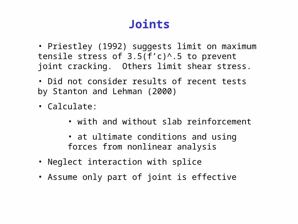
• Priestley (1992) suggests limit on maximum tensile stress of 3.5(f’c)^.5 to prevent joint cracking. Others limit shear stress.
• Did not consider results of recent tests by Stanton and Lehman (2000)
• Calculate:
• with and without slab reinforcement
• at ultimate conditions and using forces from nonlinear analysis
• Neglect interaction with splice
• Assume only part of joint is effective
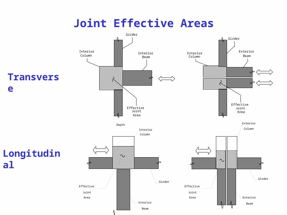
Joint Effective Areas Girder
Beam Column
Effective Joint Area
Interior Interior Exterior Beam
Girder
Column Exterior
Effective Joint Area
Depth
Girder
Beam
Column
Effective
Joint
Area
Interior
Exterior
Beam
Girder
ColumnInterior
Exterior
Effective
Joint
Area
Transverse
Longitudinal

Normalized Joint Stresses (Transverse)
Similar for interior and exterior WSDOT frames
2.7
8.32.7
6.5
Normalized vult

Normalized Joint Stresses (Longitudinal)
5.0 4.6 4.6 5.0
5.08.78.75.2
Normalized vult
1.2 2.3 2.5 2.6
5.57.97.74.6
Normalized vnonl
WSDOT Unit, including slab reinforcement
Joint shear cracking is expected in transverse direction (1st and 2nd level) and in longitudinal direction (1st level only). Cracking does not necessarily lead to collapse.
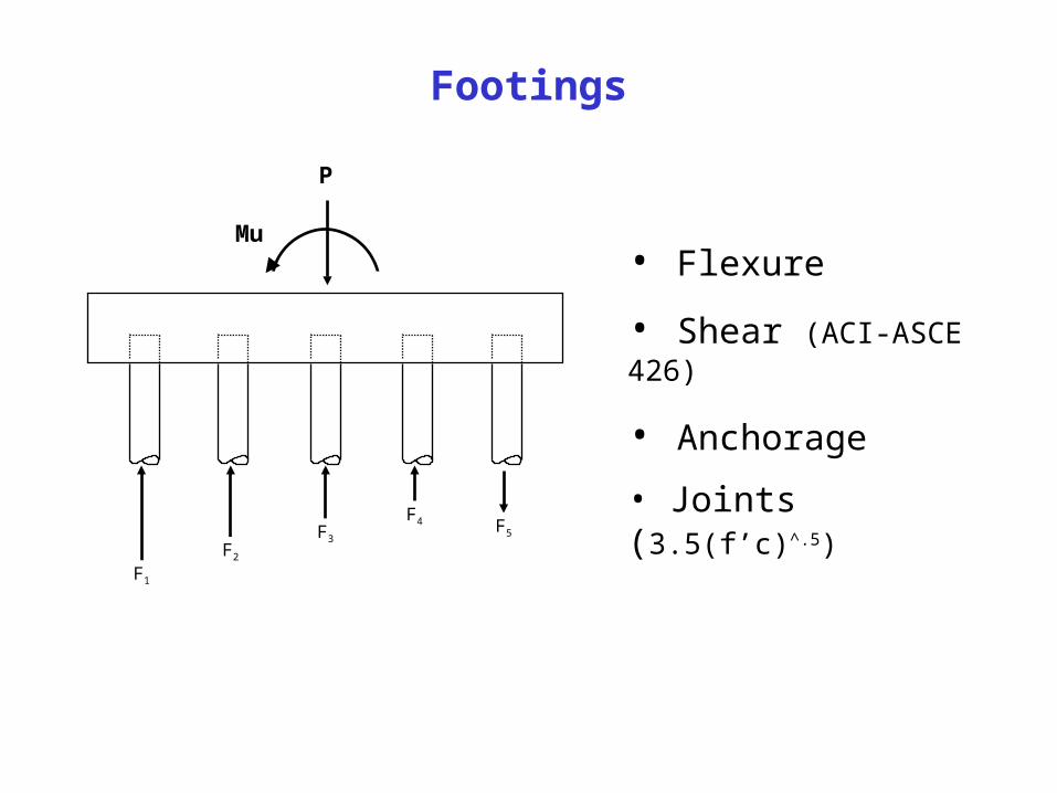
Footings
F1
F5
F4F3
F2
P
Mu• Flexure
• Shear (ACI-ASCE 426)
• Anchorage
• Joints (3.5(f’c)^.5)
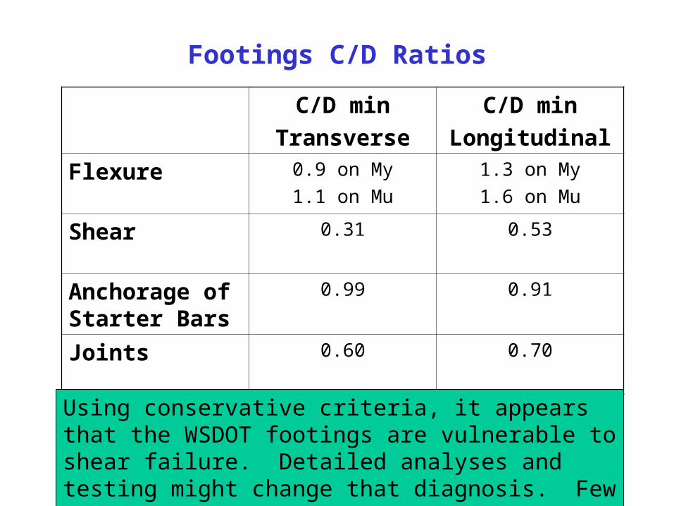
Footings C/D Ratios
C/D min
Transverse
C/D min
Longitudinal
Flexure 0.9 on My
1.1 on Mu
1.3 on My
1.6 on Mu
Shear 0.31 0.53
Anchorage of Starter Bars
0.99 0.91
Joints 0.60 0.70
Using conservative criteria, it appears that the WSDOT footings are vulnerable to shear failure. Detailed analyses and testing might change that diagnosis. Few footings have failed during earthquakes.
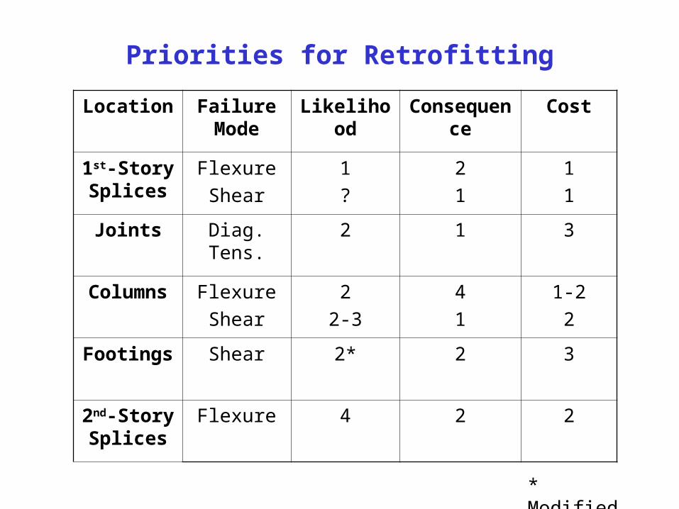
Priorities for Retrofitting
Location Failure Mode
Likelihood Consequence Cost
1st-Story Splices
Flexure
Shear
1
?
2
1
1
1
Joints Diag. Tens. 2 1 3
Columns Flexure
Shear
2
2-3
4
1
1-2
2
Footings Shear 2* 2 3
2nd-Story Splices
Flexure 4 2 2
* Modified