ROVER MOWERS LIMITED - Lawn Mower Manuals
15
Owners Manual Gebrauchsanweisung Manuel du Propriétaire Manual del Propietario Handleiding Manuale Instruzioni MODEL 50, 60 Petrol Lawnmower Motor-Rasenmäher Tondeuse à Gazon à Essence Cortadoras de Cesped a Gasolina Benzine Grasmaaimachine Falciatrice A Motore
Transcript of ROVER MOWERS LIMITED - Lawn Mower Manuals
8 13
7 12
9 14
10 15
11 16
ii
A
1mm
Rover Mowers Limited
GB Keep bystanders awayD Andere fernhaltenF Restez a l'ecart du publicSP Mantenga alos espectadores le jos de ustadNL Houd toeschouwer op afstandI Tenere lontano le persone circostanti
GB Rotating cutting bladesD Rotierende messerF Lames de coup rotativesSP Lame in movimentoNL Draaiende SnijmessenI Lama con taglio a rotazione
GB PowerstartTurn the key to the (I) position to engage the electric starter, release thekey when the engine starts and allow to return to (O) position
D Powerstart KontrollenZundschlüssel auf Stelle an (I) drehen, um den Anlasser einzuschalten.Beim Anspringen des Motors den Schlück lassen
F Contrôles de démarrage électriqueTournez la clé sur la position (I) pour engager le démarrage électrique.Relâchez la clé quand le moteur démarre et laissez retourner à laposition (O)
SP Powerstart ControlMover la llave hacia (I) las posicion para atracer el arranque electrico.Dispara la llave cuando el motor empieza a dejar a regresar al (O)posicion apagdo
NL Regulatuur bij Powerstart machinesDraai de startsleutel in postie no. (I) em de electrische starter in teschaken. Laat de startsleutel los als de motor loopt en laat hemin de (O) teruggaan
I Controlli messa in motoGirare la chiave posizione (I) per accendere il motorino elettricod'avviamento. Lasciare libera la chiave quando il motore e in moto, inmodo che ritorni in posizione (O)
GB CautionD AchtungF AttentionSP AtencionNL VoorzichtigI Attenzione!
GB Stop the engine and disconnect the spark plug lead before checking,cleaning or working on the mower
D Den motor abstellen und das Zundkerzenkabel von der Zundkerzeabziehen vor arbeiten am Maher
F Arretez le moteur et debranchez la bougie avant de verifer, nettoyer oureparer la tondeuse
SP Pare el motor y desconecte el cable de la bujf a antes de comprobar,limpiar o examinar la cortadora
NL Stop de motor en trek de bougieleabel los voor het inspecteren,schoonmaken of reparen van de maaimachine
I Fermare il motore e staccare il cavetto dalla candela prima di controllare,pulire o aggiustare la tosaerba
PAGE 10
GB Read the instructions carefullyD Lesen sie die hinweise sorgfaltigF Lisen les instructions attentivementSP Lea las instrucciones con mucho
cuidadoNL Lees de gebruiksaanwijzing
zorgruldigI Leggere attentamente le istruzioni
ROVERMOWERS LIMITED
ACN 000 257 303
Head Office and Factory: Rover Mowers Limited155 Fison Avenue West, Eagle Farm, 4009
Brisbane, Queensland, Australia.
04003632 - CE PRINTED IN AUSTRALIA © Copyright 9/02Revision H.
Para su referencia:
Vendedor .............................................
Fecha de compra ....................................
Modelo ................................................
Serie no ...............................................
Voor uw informatie:
Handelaar .............................................
Aankoopdatum.......................................
Type ...................................................
Serienummer .........................................
Dati da registrare:
Distributore ..........................................
Data d'acquito .......................................
Modello ...............................................
N.o Serie .............................................
For your record:
Dealer .................................................
Date of Purchase ....................................
Model .................................................
Serial No..............................................
Für lhre Aufzeichnung:
Händler ...............................................
Lieferdatum ..........................................
Modell Nr ............................................
Seriennummer .......................................
Pour votre information personnelle:
Fabricant ..............................................
Date d'achat ..........................................
Modèle ................................................
NO de série ...........................................
Recycled paper
GWAIL
Owners ManualGebrauchsanweisungManuel du PropriétaireManual del PropietarioHandleidingManuale Instruzioni
MODEL 50, 60
Petrol LawnmowerMotor-RasenmäherTondeuse à Gazon à EssenceCortadoras de Cesped a GasolinaBenzine GrasmaaimachineFalciatrice A Motore
These machines are covered by one or more of the following Registered Designs and or Patents;Registered Designs: Australia. 131504, 134850Patents: Australia. 713852, 745750, New Zealand. 330293, US. 6085508, UK. GR2325139
04003632-CE PRINTEDINAUSTRALIA ©Copyright1/2003 RevisionI.
3632 Imposed PDF's.indd 1 18/05/2006 2:36:05 PM
1 4
2 5
3 6
i
A
B
A
B
A
PAGE 11
Rover Mowers Limited
GB Self propelled drive controlMoved towards (I) turns the clutch on and drives the mower forward.Moved towards (O) turns the clutch off and stops the mowerdriving
D SelbetantriebbetätgungEinstellung auf (I) aktiviert die Kupplung und den Motor vorwärs.Einstellung auf (I) schaltet die kupplung aus und bringt den Mäher zumStehen
F Contrôle d'autotractionDéplacé vers (I) enclenche l'embrayage et fait avancer la tondeuse.Déplacé vers (O) décengage l'embrayage el empéche la tondeuse d'avancer
SP Autopropulsado marcas del controlMovido hacia (I) mueve el desembragador y pone a marcha el cortacesped.Movido hacia el (O) apaga el desembragador y para el cortacesped
NL Regulatuur bij relfverplaatsende machinesAls men de knop op (I) zet, is de koppeling ingeschakeld en de machinerijdt vooruit. Als de knop (O) zet, schakelt men de knoppeling uit en
de machine stopt.
I Camando trazione removente
Se mosso verso I (innestato) innesta la frizione e muove in avanti la
faiciatrice tosaerba. Se mosso verso O (disinnestato) disinnesta la
frizione e ferma la trazione della falciatrice tosaerba
GB Operator presense controlHandle moved towards the handle bars, engine and blades are free torotate. Handle released, engine and blades stop rotating
D BedieneranwesenheitakontrolleGiff in Richtung Giffbügel vorgestzt, motor und messer rotieren frei,Griff gelôst, Motor und messer stoppen
F Contrôle par opérateurPoigée avancée vers les mancherons, moteur et lames peuvent tourner.Poignée relâchée, moteur arrêtent de tourner
SP Operador de las presencias controlesMango movido hacia manillas, motor y cuchillas estanlibres de hacervucltas. Mango disparado, motor y cuchillas paran de hacer vucltas
NL Dodenmanskoop regulatuurknop die aangeeft dat de oparateuraanwezig isDe gasbedieningshendel geplaast in de richting van de hand grepen,de machine loopt en de messen draaien vrij. Gasbedieningshendel isafgezet, de machine stopt, en de messen draaicn neit meer
I Comando presenza operatore(I) Manopola mossa verso barre manubrio, motere e lame in posizionelibers e rptanti. (O) manopola disimpegnata. Motre e lame fermi
GB Throttle controlMarked for off, slow and fast positions
D GasbedienungMarkierung aus, langsam sch schnell
F Contrôle des gazMarque pour les positions arrêt, ralenti accéléré et
SP Control del acceleradorMarcado por apagado, despacio, rapido posiciones
NL Gasknop regulatuurVoorzien van markteken uit, langzaam, snel tekening
I ComandeSegno di poizione O staccato lento veloce
3632 Steel Export.PMD 11/11/2002, 10:10 AM2
Rover Mowers Limited 7. SPARE PARTS
1 A03802 Upper handle bars-Mod 602 A10016 Throttle control assembly3 A03581 Throttle cable- Quantum4 A03557 Key start housing5 A03560 Key start switch6 A07679 Ignition key7 A03741 Wiring loom- Mod 60 CE8 A03565 Cable clamp9 A03559 Battery10 A03558 Battery block11 A03556 Battery support box12 A03563 Decal- caution13 A02083 Setscrew- 5/16" x 3/4" unc.hex.14 A02012 Washer- 5/16" x 7/8" x 18g.flat15 A02223 Nyloc nut- 5/16" unc.16 A02002 Speed nut- 3/16" bsw.17 A02163 Screw- 3/16" x 1/2" mush/head18 A04060 Rivet- 73 AS 5-2
19 A03610 Foam block2021 A10524 Bale assembly- Mod 60 CE22 A10503 Handle assembly Mod.60- CE23 A02521 Spacer24 A03739 Handle grip- CE25 A03732 Cable clip- CE26 A03733 Rope stop- CE2728 A02235 Nyloc nut- 1/4" unc.29 A04083 Screw- 10 x 3/4 pan head3030 A03722 Brake cable- mod. 6031 A03756 Switch Plate
7.4 Powerstart spare parts - Series 85000, 86000
PAGE 9
Rover Mowers Limited ENGLISH PREFACE
WARNING CAUTIONFollow these instructions to avoid mower damage andpossible loss of warranty
The safety of the user and others involved. Personal Injurymay result should this information be disregarded.
CONTENTS PAGE
Preface ............................................................................ iii
Safety Instructions .......................................................... iv
1. Setting up ................................................................... 11.1 Grass catcher assembly ................................... 1
2. Before operating ........................................................ 12.1 Folding handles ............................................... 12.2 Handle bar height ............................................ 12.3 Engine lubrication ........................................... 12.4 Fuel .................................................................. 12.5 Controls ........................................................... 1
3. Operation ................................................................... 13.1 Grass catcher ................................................... 13.2 Adjusting the height of cut .............................. 13.3 To start the engine ........................................... 13.4 To stop the engine ........................................... 13.5 Self propelled mowers ..................................... 13.6 Blade brake control ......................................... 1
4. Maintenance - General .............................................. 24.1 Engine air cleaner ............................................ 24.2 Snorkel air cleaner ........................................... 24.3 Spark Plug ....................................................... 24.4 Cutting assembly ............................................. 24.5 Blade change ................................................... 24.6 Throttle control ................................................ 2
5. Maintenance - self propelled mowers ........................ 25.1 Drive chain lubrication .................................... 25.2 Drive chain adjustment.................................... 25.3 Rear drive chain inspection ............................. 35.4 Clutch adjustment ............................................ 35.5 Clutch lining inspection .................................. 35.6 Drive pawl lubrication ..................................... 35.7 Drive Wheel Cleaning ..................................... 3
6. Maintenance powerstart mowers6.1 Battery removal ............................................... 36.2 Battery installation .......................................... 36.3 Battery charging .............................................. 36.4 Care and handling............................................ 3
7. Spare parts ................................................................. 67.1 Series 85000, 86000, 96000 base .................... 67.2 Series 85000, 86000, 96000 bars .................... 77.3 Self-propelled .................................................. 87.4 Powerstart ........................................................ 9
ILLUSTRATIONS ................................................. PAGE
Figure 1. Grass catcher assembly ............................... iFigure 2. Handle bar height adjustment ..................... iFigure 3. Throttle control markings ........................... iFigure 4. Operator presence control ........................... iFigure 5. Self propelled drive control ........................ iFigure 6. Grass catcher fitment .................................. iFigure 7. Height adjustment ...................................... iiFigure 8. Blade bolt assembly ................................... iiFigure 9. Drive chain cover plate .............................. iiFigure 10. Drive chain ................................................. iiFigure 11. Drive shaft cover ........................................ iiFigure 12. Stone cover ................................................ iiFigure 13. Clutch adjustment ...................................... iiFigure 14. Drive wheel ................................................ iiFigure 15. Drive pinion ............................................... iiFigure 16. Powerstart control ...................................... ii
iii
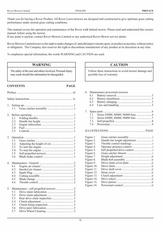
Thank you for buying a Rover Product. All Rover Lawn mowers are designed and constructed to give optimum grass cuttingperformance under normal grass cutting conditions.
This manual covers the operation and maintenance of the Rover walk behind mower. Please read and understand this ownersmanual, before using the mower.If any point is unclear, contact Rover Mowers Limited or any authorised Rover Mower service dealer.
Rover Mowers Limited reserves the right to make changes of, and add improvements upon, its product at anytime, without noticeor obligation. The Company also reserves the right to discontinue manufacture of any product at its discretion at any time.
To emphasise special information, the words WARNING and CAUTION are used.
Rover Mowers Limited7. SPARE PARTS
1A03300Base12A03510Height adjustment rack13A03456Rear Flap14A03325Spring- rear flap15A03455Handle- rear flap16A03126Pivot bush27A10148Conbar assembly18A02591Conbar spring19A03515Axle bracket- RH.110A03514Axle bracket- LH.111A03516Clamp bolt212A02051Woodruff key113A01486Disc boss114A00293Disc assembly115A01716Backplate116A03830Blade- standard416A03930Blade- Mulch N Catch17A00673Blade bolt kit218A10154Disc bolt kit119A10140Front axle assembly- professional119A10527Front axle assembly- professional120A03450Front axle bush221A03459Wheel seal422A03320Front wheel assembly223A03353Wheel bearing824A03414Wheel cap425A03306Pivot rod126A03743Decal- Warning1
27A03492Decal- sound level128A03409Nameplate129373109Tension washer430A03092Ratchet plate431S2501116Ratchet plate232290112Poprivet- 73 AS 6-4 blind1033A02127Taptite- 3/8" - 16 HWH x 1" Ind.hex.W/H Duo.334 *Decal- Model135A04052Self tapping screw- 10 x 5/8" pan ph/head236A03549Cable clip137A03323Plug chain slot- model 50138A010141Rear axle assembly- model 50139A03313Rear axle bush- model 50240A03250Plastic handle141A10284Height adj. lever assembly142A03336Packing plate143A02066Rivet244A03319Rear wheel assembly245A03303Grass deflector146A10381Rear stoneguard- Mod. 50146A03604Rear stoneguard- Mod. 60147A02071Rivet- 73 SS 4-3248A02235Nyloc nut- 1/4" unc.249A03472Decal- turbothrust150A03927Nose comb151A04108Rivet252A04099Washer- 3/16" x 3/4"253A04111Screw2
7.1 Series 85000, 86000 and 96000 base spare parts
PAGE 6
26
Rover Mowers Limited ENGLISH4. MAINTENANCE GENERAL
5. MAINTENANCE - Self propelled mowers
5.1 Drive chain lubrication
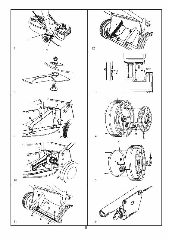
1.Remove the spark plug lead.2.Remove the cover plate screws (a) and lift off the cover plate (b).
Figure 9.3.Support the rear wheels off the ground to enable the drive to be
rotated.4.Use SAE 30 oil and lubricate the drive chains atpoint (a) whilst
the chain is being rotated. Figure 10.5.Replace the chain cover plate and secure.6.Replace the spark plug lead.
5.2 Drive chain adjustment
Front drive chain1.Remove the spark plug lead.2.Remove the cover plate.3.Loosen the chain tensioner bolt (b) and move the chain tensioner to
give a 3 mm deflection on the drive chain. Figure 10.4.Tighten the chain tensioner bolt and rotate the drive wheels to check
the drive chain for tight spots.5.Replace the cover plate.
Rear drive chain1.Remove the spark plug lead.2.Loosen the rear drive chain tension nut (c) and slide it upwards to
tighten the rear drive chain. Figure 9.3.Retighten the rear drive chain tensioner nut and rotate the rear drive
wheels to check for tight spots.4.Replace the spark plug lead.
5.3 Rear drive chain inspection
1.Remove the spark plug lead.2.Remove the drive shaft cover plate retaining screws (a) and remove
cover plate (b). Figure 11.3.Remove the stone guard retaining screws (c) and remove the stone
guard. Figure 11.4.Remove the chain guard nuts (d) and slide the chain guard out of the
way. Figure 12.5.Inspect the drive chain and axle sprocket and replace if found to have
excessive wear.6.Replace the stone guard and drive shaft axle plate.7.Replace the spark plug lead.
5.4 Clutch adjustment
1.Remove the spark plug lead.2.Loosen the locknut (a) and turn the adjuster (b) clockwise until the
clutch is felt to drag. Figure 13.3.Back off the adjuster anti-clockwise 2-3 turns and retighten locknut
(a).4.Replace the spark plug lead.
4.1 Engine air cleaner
Refer to the engine manufacture's instructions for detailed cleaninginstructions.The engine air cleaner element must be serviced after each 25 hours ofnormal mowing. The element must be serviced more regularly if themower is used in dusty conditions.
4.2 Snorkel air intake
The snorkel air cleaner element must be serviced after each 50 hours ofnormal mowing. The element must be serviced more regularly if themower is used in dusty conditions.
1.Disconnect the air tube from the element holder.2.Remove the holder cap.3.Remove the cartridge and tap gently on a flat surface to remove dirt.4.Replace element in holder and replace holder cap.5.Replace the air tube to the bottom of the element holder.
NOTE: Quantum engines fitted with a Remote snorkel airintake are not fitted with an air cleaner element. Notetheair cleaner element on this model is located on the engine.
CAUTION
Do not allow dirt to enter the air tube, engine damage may occur.Check the condition of the air tube regularly and replace ifdamaged.
4.3 Spark plug
For best results remove and check the condition of the spark plug every25 hours of use.
1.Stop the engine and remove the spark plug lead.2.Clean dirt from around the spark plug and remove the spark plug.3.If a new spark plug is required use a Champion RJ19LM or
equivalent and set the electrode gap at 0.7 to 0.8 mm.4.Screw the spark plug into the engine and tighten to 20NM.
4.4 Cutting assembly
1.Disconnect the spark plug lead.2.Move the height of cut lever to the high cut position, and fold the
handle bars.3.Tilt the mower so that the spark plug is up.4.Inspect the cutting assembly for damage and wear.5.Check the disc retaining bolts. Tighten the centre bolt to 48 Nm.and
the three concentric bolts to 14 Nm.6.Return mower to its normal position and replace the spark plug lead.
WARNING
Remove the spark plug lead before working on cutting assembly.Do not work on the cutting assembly without wearing gloves.
4.5 Blade change
1.Disconnect the spark plug lead.2.Set the mower to the high cut position.3.Lift the rear flap on rear catcher mowers and prop open the flap to
give access to the blades.Tilt utility mowers so that the spark plug is up.
4.Remove the blade, blade retaining bolts, nuts and washers anddiscard. Retain only the ‘D’ plates.
5.Fit new blades, blade bolts, washers, and nuts in sets to maintainbalance. Figure 8.
6.Tighten the blade nuts to 16 NM. Check the blades are free to movewhen the blade nut is tensioned.
7.Remove the flap prop or lower the mower to the ground and replacethe spark plug lead.
4.6 Throttle control
Each 25 hours of mowing use a small amount of light oil to lubricatethe throttle control lever.
Page 2
CAUTION
Do not over tighten the spark plug as engine damage may occur.
Rover Mowers Limited7. SPARE PARTS
PAGE 8
1A02102Washer- Avdel 7601/00102A10177Clutch lever3A03365Clutch cable4A07822Cable tie5A03314Rear axle support6A03391Stoneguard mount bracket7A03383Rear stoneguard- 960127A10381Rear stoneguard- 86012, 860408A03393Drive shaft cover9A02090Circlip- 1400/1210A03373Pawl retainer washer11A03371Drive pinion- RH12A03372Pawl13A03361Bearing- 6001 DDU14A07675Nylon bush15A10172Rear axle assembly16A03366Rear chain guard17A03394Felt seal18 A02069Roll pin- 1/8" x 3/4"19A03368Rear drive shaft sprocket20A03382Dust seal21A03353Wheel bearing22A03352Geared wheel hub23A03441Washer plate
24A03414Wheel cap25A03369Drive shaft26A03377Rear drive chain27A03364Cable support bracket- RH28A03367Chain tensioner29A03360Clutch engagement bush30A10171Driver clutch plate31A03358Clutch spring32A10170Driven clutch plate33A03359Clutch support shaft34A03550Drive chain housing- LH35A03363Cable support bracket- LH36 A03370Drive pinion- LH37 A04052Self tapping screw- 10 x 5/8" pan ph/head38A03552Chain guard cover plate39A03551Drive chain housing- RH40A03386Felt seal41 A02070Roll pin- 3/16" x 7/8"42A03354Sprocket PTO.43A03376Front drive chain44A03375Pivot rod45A03250Handle46 A02146Setscrew- 1/4" x 3/4" unc.hex47 A02214Setscrew- 1/4" x 5/8" unc.hex
48 A02078Setscrew- 1/4" x 1/2" unc.hex49 A02081Setscrew- 1/4" x 1-3/4" unc.hex50 A02235Nyloc nut- 1/4" unc.51 S2491162Nut- 1/4" unc.square pressed52 A02001Nut- 1/4" unc.hex53 A03092Washer- Avdel 7301/001654 A02030Washer- 5/16" x 5/8" x 18g.flat55 A02209Washer- 1/4" x 5/8" x 18g.flat56 A02044Washer- 1/4" internal shakeproof57S373109Tension washer58A10146Wheel assembly59S2501108Washer- Avdel 7301/000860A10284Height adjustment lever assembly61 A02118Rivet- 3/4" x 1/4" flat head62A03336Plate63S3521047Wheel plug64A03470Chain guide65 290112Rivet- 73 AS 6-4 blind66A03390Clutch plate lining67A03384Tyre68A10524Bale assembly CE69A10503Handle assembly CE70A03739Handle grip CE71A02521Spacer CE72A03604Rear extension- Mod. 60
7.3 Self propelled spare parts
Rover Mowers LimitedENGLISHSAFETY INSTRUCTIONS
Safety Instructions1. Training
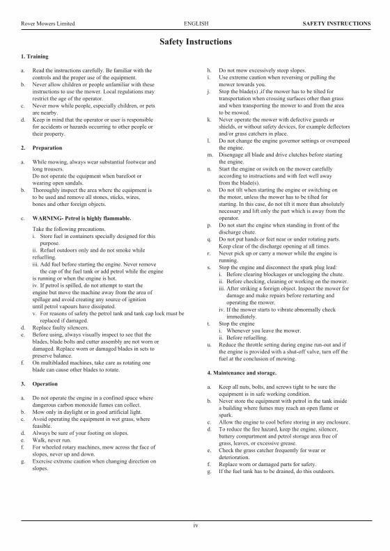
a.Read the instructions carefully. Be familiar with thecontrols and the proper use of the equipment.
b.Never allow children or people unfamiliar with theseinstructions to use the mower. Local regulations mayrestrict the age of the operator.
c.Never mow while people, especially children, or petsare nearby.
d.Keep in mind that the operator or user is responsiblefor accidents or hazards occurring to other people ortheir property.
2.Preparation
a.While mowing, always wear substantial footwear andlong trousers.Do not operate the equipment when barefoot orwearing open sandals.
b.Thoroughly inspect the area where the equipment isto be used and remove all stones, sticks, wires,bones and other foreign objects.
c.WARNING- Petrol is highly flammable.
Take the following precautions.i.Store fuel in containers specially designed for this
purpose.ii.Refuel outdoors only and do not smoke whilerefuelling.iii.Add fuel before starting the engine. Never remove
the cap of the fuel tank or add petrol while the engineis running or when the engine is hot.iv.If petrol is spilled, do not attempt to start theengine but move the machine away from the area ofspillage and avoid creating any source of ignitionuntil petrol vapours have dissipated.v.For reasons of safety the petrol tank and tank cap lock must be
replaced if damaged.d.Replace faulty silencers.e.Before using, always visually inspect to see that the
blades, blade bolts and cutter assembly are not worn ordamaged. Replace worn or damaged blades in sets topreserve balance.
f.On multibladed machines, take care as rotating oneblade can cause other blades to rotate.
3.Operation
a.Do not operate the engine in a confined space wheredangerous carbon monoxide fumes can collect.
b.Mow only in daylight or in good artificial light.c.Avoid operating the equipment in wet grass, where
feasible.d.Always be sure of your footing on slopes.e.Walk, never run.f.For wheeled rotary machines, mow across the face of
slopes, never up and down.g.Exercise extreme caution when changing direction on
slopes.
h.Do not mow excessively steep slopes.i.Use extreme caution when reversing or pulling the
mower towards you.j.Stop the blade(s) ,if the mower has to be tilted for
transportation when crossing surfaces other than grassand when transporting the mower to and from the areato be mowed.
k.Never operate the mower with defective guards orshields, or without safety devices, for example deflectorsand/or grass catchers in place.
l.Do not change the engine governor settings or overspeedthe engine.
m.Disengage all blade and drive clutches before startingthe engine.
n.Start the engine or switch on the mower carefullyaccording to instructions and with feet well awayfrom the blade(s).
o.Do not tilt when starting the engine or switching onthe motor, unless the mower has to be tilted forstarting. In this case, do not tilt it more than absolutelynecessary and lift only the part which is away from theoperator.
p.Do not start the engine when standing in front of thedischarge chute.
q.Do not put hands or feet near or under rotating parts.Keep clear of the discharge opening at all times.
r.Never pick up or carry a mower while the engine isrunning.
s.Stop the engine and disconnect the spark plug lead:i.Before clearing blockages or unclogging the chute.ii.Before checking, cleaning or working on the mower.iii.After striking a foreign object. Inspect the mower for
damage and make repairs before restarting andoperating the mower.
iv.If the mower starts to vibrate abnormally checkimmediately.
t.Stop the enginei.Whenever you leave the mower.ii.Before refuelling.
u.Reduce the throttle setting during engine run-out and ifthe engine is provided with a shut-off valve, turn off thefuel at the conclusion of mowing.
4. Maintenance and storage.
a.Keep all nuts, bolts, and screws tight to be sure theequipment is in safe working condition.
b.Never store the equipment with petrol in the tank insidea building where fumes may reach an open flame orspark.
c.Allow the engine to cool before storing in any enclosure.d.To reduce the fire hazard, keep the engine, silencer,
battery compartment and petrol storage area free ofgrass, leaves, or excessive grease.
e.Check the grass catcher frequently for wear ordeterioration.
f.Replace worn or damaged parts for safety.g.If the fuel tank has to be drained, do this outdoors.
iv
3632 Imposed PDF's.indd 218/05/2006 2:36:08 PM
8 13
7 12
9 14
10 15
11 16
ii
A
1mm
Rover Mowers Limited
GB Keep bystanders awayD Andere fernhaltenF Restez a l'ecart du publicSP Mantenga alos espectadores le jos de ustadNL Houd toeschouwer op afstandI Tenere lontano le persone circostanti
GB Rotating cutting bladesD Rotierende messerF Lames de coup rotativesSP Lame in movimentoNL Draaiende SnijmessenI Lama con taglio a rotazione
GB PowerstartTurn the key to the (I) position to engage the electric starter, release thekey when the engine starts and allow to return to (O) position
D Powerstart KontrollenZundschlüssel auf Stelle an (I) drehen, um den Anlasser einzuschalten.Beim Anspringen des Motors den Schlück lassen
F Contrôles de démarrage électriqueTournez la clé sur la position (I) pour engager le démarrage électrique.Relâchez la clé quand le moteur démarre et laissez retourner à laposition (O)
SP Powerstart ControlMover la llave hacia (I) las posicion para atracer el arranque electrico.Dispara la llave cuando el motor empieza a dejar a regresar al (O)posicion apagdo
NL Regulatuur bij Powerstart machinesDraai de startsleutel in postie no. (I) em de electrische starter in teschaken. Laat de startsleutel los als de motor loopt en laat hemin de (O) teruggaan
I Controlli messa in motoGirare la chiave posizione (I) per accendere il motorino elettricod'avviamento. Lasciare libera la chiave quando il motore e in moto, inmodo che ritorni in posizione (O)
GB CautionD AchtungF AttentionSP AtencionNL VoorzichtigI Attenzione!
GB Stop the engine and disconnect the spark plug lead before checking,cleaning or working on the mower
D Den motor abstellen und das Zundkerzenkabel von der Zundkerzeabziehen vor arbeiten am Maher
F Arretez le moteur et debranchez la bougie avant de verifer, nettoyer oureparer la tondeuse
SP Pare el motor y desconecte el cable de la bujf a antes de comprobar,limpiar o examinar la cortadora
NL Stop de motor en trek de bougieleabel los voor het inspecteren,schoonmaken of reparen van de maaimachine
I Fermare il motore e staccare il cavetto dalla candela prima di controllare,pulire o aggiustare la tosaerba
PAGE 10
GB Read the instructions carefullyD Lesen sie die hinweise sorgfaltigF Lisen les instructions attentivementSP Lea las instrucciones con mucho
cuidadoNL Lees de gebruiksaanwijzing
zorgruldigI Leggere attentamente le istruzioni
ROVERMOWERS LIMITED
ACN 000 257 303
Head Office and Factory: Rover Mowers Limited155 Fison Avenue West, Eagle Farm, 4009
Brisbane, Queensland, Australia.
04003632 - CE PRINTED IN AUSTRALIA © Copyright 9/02Revision H.
Para su referencia:
Vendedor .............................................
Fecha de compra ....................................
Modelo ................................................
Serie no ...............................................
Voor uw informatie:
Handelaar .............................................
Aankoopdatum.......................................
Type ...................................................
Serienummer .........................................
Dati da registrare:
Distributore ..........................................
Data d'acquito .......................................
Modello ...............................................
N.o Serie .............................................
For your record:
Dealer .................................................
Date of Purchase ....................................
Model .................................................
Serial No..............................................
Für lhre Aufzeichnung:
Händler ...............................................
Lieferdatum ..........................................
Modell Nr ............................................
Seriennummer .......................................
Pour votre information personnelle:
Fabricant ..............................................
Date d'achat ..........................................
Modèle ................................................
NO de série ...........................................
Recycled paper
GWAIL
Owners ManualGebrauchsanweisungManuel du PropriétaireManual del PropietarioHandleidingManuale Instruzioni
MODEL 50, 60
Petrol LawnmowerMotor-RasenmäherTondeuse à Gazon à EssenceCortadoras de Cesped a GasolinaBenzine GrasmaaimachineFalciatrice A Motore
These machines are covered by one or more of the following Registered Designs and or Patents;Registered Designs: Australia. 131504, 134850Patents: Australia. 713852, 745750, New Zealand. 330293, US. 6085508, UK. GR2325139
04003632-CE PRINTEDINAUSTRALIA ©Copyright1/2003 RevisionI.
3632 Imposed PDF's.indd 1 18/05/2006 2:36:05 PM
1 4
2 5
3 6
i
A
B
A
B
A
PAGE 11
Rover Mowers Limited
GB Self propelled drive controlMoved towards (I) turns the clutch on and drives the mower forward.Moved towards (O) turns the clutch off and stops the mowerdriving
D SelbetantriebbetätgungEinstellung auf (I) aktiviert die Kupplung und den Motor vorwärs.Einstellung auf (I) schaltet die kupplung aus und bringt den Mäher zumStehen
F Contrôle d'autotractionDéplacé vers (I) enclenche l'embrayage et fait avancer la tondeuse.Déplacé vers (O) décengage l'embrayage el empéche la tondeuse d'avancer
SP Autopropulsado marcas del controlMovido hacia (I) mueve el desembragador y pone a marcha el cortacesped.Movido hacia el (O) apaga el desembragador y para el cortacesped
NL Regulatuur bij relfverplaatsende machinesAls men de knop op (I) zet, is de koppeling ingeschakeld en de machinerijdt vooruit. Als de knop (O) zet, schakelt men de knoppeling uit en
de machine stopt.
I Camando trazione removente
Se mosso verso I (innestato) innesta la frizione e muove in avanti la
faiciatrice tosaerba. Se mosso verso O (disinnestato) disinnesta la
frizione e ferma la trazione della falciatrice tosaerba
GB Operator presense controlHandle moved towards the handle bars, engine and blades are free torotate. Handle released, engine and blades stop rotating
D BedieneranwesenheitakontrolleGiff in Richtung Giffbügel vorgestzt, motor und messer rotieren frei,Griff gelôst, Motor und messer stoppen
F Contrôle par opérateurPoigée avancée vers les mancherons, moteur et lames peuvent tourner.Poignée relâchée, moteur arrêtent de tourner
SP Operador de las presencias controlesMango movido hacia manillas, motor y cuchillas estanlibres de hacervucltas. Mango disparado, motor y cuchillas paran de hacer vucltas
NL Dodenmanskoop regulatuurknop die aangeeft dat de oparateuraanwezig isDe gasbedieningshendel geplaast in de richting van de hand grepen,de machine loopt en de messen draaien vrij. Gasbedieningshendel isafgezet, de machine stopt, en de messen draaicn neit meer
I Comando presenza operatore(I) Manopola mossa verso barre manubrio, motere e lame in posizionelibers e rptanti. (O) manopola disimpegnata. Motre e lame fermi
GB Throttle controlMarked for off, slow and fast positions
D GasbedienungMarkierung aus, langsam sch schnell
F Contrôle des gazMarque pour les positions arrêt, ralenti accéléré et
SP Control del acceleradorMarcado por apagado, despacio, rapido posiciones
NL Gasknop regulatuurVoorzien van markteken uit, langzaam, snel tekening
I ComandeSegno di poizione O staccato lento veloce
3632 Steel Export.PMD 11/11/2002, 10:10 AM2
Rover Mowers Limited 7. SPARE PARTS
1 A03802 Upper handle bars-Mod 602 A10016 Throttle control assembly3 A03581 Throttle cable- Quantum4 A03557 Key start housing5 A03560 Key start switch6 A07679 Ignition key7 A03741 Wiring loom- Mod 60 CE8 A03565 Cable clamp9 A03559 Battery10 A03558 Battery block11 A03556 Battery support box12 A03563 Decal- caution13 A02083 Setscrew- 5/16" x 3/4" unc.hex.14 A02012 Washer- 5/16" x 7/8" x 18g.flat15 A02223 Nyloc nut- 5/16" unc.16 A02002 Speed nut- 3/16" bsw.17 A02163 Screw- 3/16" x 1/2" mush/head18 A04060 Rivet- 73 AS 5-2
19 A03610 Foam block2021 A10524 Bale assembly- Mod 60 CE22 A10503 Handle assembly Mod.60- CE23 A02521 Spacer24 A03739 Handle grip- CE25 A03732 Cable clip- CE26 A03733 Rope stop- CE2728 A02235 Nyloc nut- 1/4" unc.29 A04083 Screw- 10 x 3/4 pan head3030 A03722 Brake cable- mod. 6031 A03756 Switch Plate
7.4 Powerstart spare parts - Series 85000, 86000
PAGE 9
Rover Mowers Limited ENGLISH PREFACE
WARNING CAUTIONFollow these instructions to avoid mower damage andpossible loss of warranty
The safety of the user and others involved. Personal Injurymay result should this information be disregarded.
CONTENTS PAGE
Preface ............................................................................ iii
Safety Instructions .......................................................... iv
1. Setting up ................................................................... 11.1 Grass catcher assembly ................................... 1
2. Before operating ........................................................ 12.1 Folding handles ............................................... 12.2 Handle bar height ............................................ 12.3 Engine lubrication ........................................... 12.4 Fuel .................................................................. 12.5 Controls ........................................................... 1
3. Operation ................................................................... 13.1 Grass catcher ................................................... 13.2 Adjusting the height of cut .............................. 13.3 To start the engine ........................................... 13.4 To stop the engine ........................................... 13.5 Self propelled mowers ..................................... 13.6 Blade brake control ......................................... 1
4. Maintenance - General .............................................. 24.1 Engine air cleaner ............................................ 24.2 Snorkel air cleaner ........................................... 24.3 Spark Plug ....................................................... 24.4 Cutting assembly ............................................. 24.5 Blade change ................................................... 24.6 Throttle control ................................................ 2
5. Maintenance - self propelled mowers ........................ 25.1 Drive chain lubrication .................................... 25.2 Drive chain adjustment.................................... 25.3 Rear drive chain inspection ............................. 35.4 Clutch adjustment ............................................ 35.5 Clutch lining inspection .................................. 35.6 Drive pawl lubrication ..................................... 35.7 Drive Wheel Cleaning ..................................... 3
6. Maintenance powerstart mowers6.1 Battery removal ............................................... 36.2 Battery installation .......................................... 36.3 Battery charging .............................................. 36.4 Care and handling............................................ 3
7. Spare parts ................................................................. 67.1 Series 85000, 86000, 96000 base .................... 67.2 Series 85000, 86000, 96000 bars .................... 77.3 Self-propelled .................................................. 87.4 Powerstart ........................................................ 9
ILLUSTRATIONS ................................................. PAGE
Figure 1. Grass catcher assembly ............................... iFigure 2. Handle bar height adjustment ..................... iFigure 3. Throttle control markings ........................... iFigure 4. Operator presence control ........................... iFigure 5. Self propelled drive control ........................ iFigure 6. Grass catcher fitment .................................. iFigure 7. Height adjustment ...................................... iiFigure 8. Blade bolt assembly ................................... iiFigure 9. Drive chain cover plate .............................. iiFigure 10. Drive chain ................................................. iiFigure 11. Drive shaft cover ........................................ iiFigure 12. Stone cover ................................................ iiFigure 13. Clutch adjustment ...................................... iiFigure 14. Drive wheel ................................................ iiFigure 15. Drive pinion ............................................... iiFigure 16. Powerstart control ...................................... ii
iii
Thank you for buying a Rover Product. All Rover Lawn mowers are designed and constructed to give optimum grass cuttingperformance under normal grass cutting conditions.
This manual covers the operation and maintenance of the Rover walk behind mower. Please read and understand this ownersmanual, before using the mower.If any point is unclear, contact Rover Mowers Limited or any authorised Rover Mower service dealer.
Rover Mowers Limited reserves the right to make changes of, and add improvements upon, its product at anytime, without noticeor obligation. The Company also reserves the right to discontinue manufacture of any product at its discretion at any time.
To emphasise special information, the words WARNING and CAUTION are used.
Rover Mowers Limited7. SPARE PARTS
1A03300Base12A03510Height adjustment rack13A03456Rear Flap14A03325Spring- rear flap15A03455Handle- rear flap16A03126Pivot bush27A10148Conbar assembly18A02591Conbar spring19A03515Axle bracket- RH.110A03514Axle bracket- LH.111A03516Clamp bolt212A02051Woodruff key113A01486Disc boss114A00293Disc assembly115A01716Backplate116A03830Blade- standard416A03930Blade- Mulch N Catch17A00673Blade bolt kit218A10154Disc bolt kit119A10140Front axle assembly- professional119A10527Front axle assembly- professional120A03450Front axle bush221A03459Wheel seal422A03320Front wheel assembly223A03353Wheel bearing824A03414Wheel cap425A03306Pivot rod126A03743Decal- Warning1
27A03492Decal- sound level128A03409Nameplate129373109Tension washer430A03092Ratchet plate431S2501116Ratchet plate232290112Poprivet- 73 AS 6-4 blind1033A02127Taptite- 3/8" - 16 HWH x 1" Ind.hex.W/H Duo.334 *Decal- Model135A04052Self tapping screw- 10 x 5/8" pan ph/head236A03549Cable clip137A03323Plug chain slot- model 50138A010141Rear axle assembly- model 50139A03313Rear axle bush- model 50240A03250Plastic handle141A10284Height adj. lever assembly142A03336Packing plate143A02066Rivet244A03319Rear wheel assembly245A03303Grass deflector146A10381Rear stoneguard- Mod. 50146A03604Rear stoneguard- Mod. 60147A02071Rivet- 73 SS 4-3248A02235Nyloc nut- 1/4" unc.249A03472Decal- turbothrust150A03927Nose comb151A04108Rivet252A04099Washer- 3/16" x 3/4"253A04111Screw2
7.1 Series 85000, 86000 and 96000 base spare parts
PAGE 6
26
Rover Mowers Limited ENGLISH4. MAINTENANCE GENERAL
5. MAINTENANCE - Self propelled mowers
5.1 Drive chain lubrication
1.Remove the spark plug lead.2.Remove the cover plate screws (a) and lift off the cover plate (b).
Figure 9.3.Support the rear wheels off the ground to enable the drive to be
rotated.4.Use SAE 30 oil and lubricate the drive chains atpoint (a) whilst
the chain is being rotated. Figure 10.5.Replace the chain cover plate and secure.6.Replace the spark plug lead.
5.2 Drive chain adjustment
Front drive chain1.Remove the spark plug lead.2.Remove the cover plate.3.Loosen the chain tensioner bolt (b) and move the chain tensioner to
give a 3 mm deflection on the drive chain. Figure 10.4.Tighten the chain tensioner bolt and rotate the drive wheels to check
the drive chain for tight spots.5.Replace the cover plate.
Rear drive chain1.Remove the spark plug lead.2.Loosen the rear drive chain tension nut (c) and slide it upwards to
tighten the rear drive chain. Figure 9.3.Retighten the rear drive chain tensioner nut and rotate the rear drive
wheels to check for tight spots.4.Replace the spark plug lead.
5.3 Rear drive chain inspection
1.Remove the spark plug lead.2.Remove the drive shaft cover plate retaining screws (a) and remove
cover plate (b). Figure 11.3.Remove the stone guard retaining screws (c) and remove the stone
guard. Figure 11.4.Remove the chain guard nuts (d) and slide the chain guard out of the
way. Figure 12.5.Inspect the drive chain and axle sprocket and replace if found to have
excessive wear.6.Replace the stone guard and drive shaft axle plate.7.Replace the spark plug lead.
5.4 Clutch adjustment
1.Remove the spark plug lead.2.Loosen the locknut (a) and turn the adjuster (b) clockwise until the
clutch is felt to drag. Figure 13.3.Back off the adjuster anti-clockwise 2-3 turns and retighten locknut
(a).4.Replace the spark plug lead.
4.1 Engine air cleaner
Refer to the engine manufacture's instructions for detailed cleaninginstructions.The engine air cleaner element must be serviced after each 25 hours ofnormal mowing. The element must be serviced more regularly if themower is used in dusty conditions.
4.2 Snorkel air intake
The snorkel air cleaner element must be serviced after each 50 hours ofnormal mowing. The element must be serviced more regularly if themower is used in dusty conditions.
1.Disconnect the air tube from the element holder.2.Remove the holder cap.3.Remove the cartridge and tap gently on a flat surface to remove dirt.4.Replace element in holder and replace holder cap.5.Replace the air tube to the bottom of the element holder.
NOTE: Quantum engines fitted with a Remote snorkel airintake are not fitted with an air cleaner element. Notetheair cleaner element on this model is located on the engine.
CAUTION
Do not allow dirt to enter the air tube, engine damage may occur.Check the condition of the air tube regularly and replace ifdamaged.
4.3 Spark plug
For best results remove and check the condition of the spark plug every25 hours of use.
1.Stop the engine and remove the spark plug lead.2.Clean dirt from around the spark plug and remove the spark plug.3.If a new spark plug is required use a Champion RJ19LM or
equivalent and set the electrode gap at 0.7 to 0.8 mm.4.Screw the spark plug into the engine and tighten to 20NM.
4.4 Cutting assembly
1.Disconnect the spark plug lead.2.Move the height of cut lever to the high cut position, and fold the
handle bars.3.Tilt the mower so that the spark plug is up.4.Inspect the cutting assembly for damage and wear.5.Check the disc retaining bolts. Tighten the centre bolt to 48 Nm.and
the three concentric bolts to 14 Nm.6.Return mower to its normal position and replace the spark plug lead.
WARNING
Remove the spark plug lead before working on cutting assembly.Do not work on the cutting assembly without wearing gloves.
4.5 Blade change
1.Disconnect the spark plug lead.2.Set the mower to the high cut position.3.Lift the rear flap on rear catcher mowers and prop open the flap to
give access to the blades.Tilt utility mowers so that the spark plug is up.
4.Remove the blade, blade retaining bolts, nuts and washers anddiscard. Retain only the ‘D’ plates.
5.Fit new blades, blade bolts, washers, and nuts in sets to maintainbalance. Figure 8.
6.Tighten the blade nuts to 16 NM. Check the blades are free to movewhen the blade nut is tensioned.
7.Remove the flap prop or lower the mower to the ground and replacethe spark plug lead.
4.6 Throttle control
Each 25 hours of mowing use a small amount of light oil to lubricatethe throttle control lever.
Page 2
CAUTION
Do not over tighten the spark plug as engine damage may occur.
Rover Mowers Limited7. SPARE PARTS
PAGE 8
1A02102Washer- Avdel 7601/00102A10177Clutch lever3A03365Clutch cable4A07822Cable tie5A03314Rear axle support6A03391Stoneguard mount bracket7A03383Rear stoneguard- 960127A10381Rear stoneguard- 86012, 860408A03393Drive shaft cover9A02090Circlip- 1400/1210A03373Pawl retainer washer11A03371Drive pinion- RH12A03372Pawl13A03361Bearing- 6001 DDU14A07675Nylon bush15A10172Rear axle assembly16A03366Rear chain guard17A03394Felt seal18 A02069Roll pin- 1/8" x 3/4"19A03368Rear drive shaft sprocket20A03382Dust seal21A03353Wheel bearing22A03352Geared wheel hub23A03441Washer plate
24A03414Wheel cap25A03369Drive shaft26A03377Rear drive chain27A03364Cable support bracket- RH28A03367Chain tensioner29A03360Clutch engagement bush30A10171Driver clutch plate31A03358Clutch spring32A10170Driven clutch plate33A03359Clutch support shaft34A03550Drive chain housing- LH35A03363Cable support bracket- LH36 A03370Drive pinion- LH37 A04052Self tapping screw- 10 x 5/8" pan ph/head38A03552Chain guard cover plate39A03551Drive chain housing- RH40A03386Felt seal41 A02070Roll pin- 3/16" x 7/8"42A03354Sprocket PTO.43A03376Front drive chain44A03375Pivot rod45A03250Handle46 A02146Setscrew- 1/4" x 3/4" unc.hex47 A02214Setscrew- 1/4" x 5/8" unc.hex
48 A02078Setscrew- 1/4" x 1/2" unc.hex49 A02081Setscrew- 1/4" x 1-3/4" unc.hex50 A02235Nyloc nut- 1/4" unc.51 S2491162Nut- 1/4" unc.square pressed52 A02001Nut- 1/4" unc.hex53 A03092Washer- Avdel 7301/001654 A02030Washer- 5/16" x 5/8" x 18g.flat55 A02209Washer- 1/4" x 5/8" x 18g.flat56 A02044Washer- 1/4" internal shakeproof57S373109Tension washer58A10146Wheel assembly59S2501108Washer- Avdel 7301/000860A10284Height adjustment lever assembly61 A02118Rivet- 3/4" x 1/4" flat head62A03336Plate63S3521047Wheel plug64A03470Chain guide65 290112Rivet- 73 AS 6-4 blind66A03390Clutch plate lining67A03384Tyre68A10524Bale assembly CE69A10503Handle assembly CE70A03739Handle grip CE71A02521Spacer CE72A03604Rear extension- Mod. 60
7.3 Self propelled spare parts
Rover Mowers LimitedENGLISHSAFETY INSTRUCTIONS
Safety Instructions1. Training
a.Read the instructions carefully. Be familiar with thecontrols and the proper use of the equipment.
b.Never allow children or people unfamiliar with theseinstructions to use the mower. Local regulations mayrestrict the age of the operator.
c.Never mow while people, especially children, or petsare nearby.
d.Keep in mind that the operator or user is responsiblefor accidents or hazards occurring to other people ortheir property.
2.Preparation
a.While mowing, always wear substantial footwear andlong trousers.Do not operate the equipment when barefoot orwearing open sandals.
b.Thoroughly inspect the area where the equipment isto be used and remove all stones, sticks, wires,bones and other foreign objects.
c.WARNING- Petrol is highly flammable.
Take the following precautions.i.Store fuel in containers specially designed for this
purpose.ii.Refuel outdoors only and do not smoke whilerefuelling.iii.Add fuel before starting the engine. Never remove
the cap of the fuel tank or add petrol while the engineis running or when the engine is hot.iv.If petrol is spilled, do not attempt to start theengine but move the machine away from the area ofspillage and avoid creating any source of ignitionuntil petrol vapours have dissipated.v.For reasons of safety the petrol tank and tank cap lock must be
replaced if damaged.d.Replace faulty silencers.e.Before using, always visually inspect to see that the
blades, blade bolts and cutter assembly are not worn ordamaged. Replace worn or damaged blades in sets topreserve balance.
f.On multibladed machines, take care as rotating oneblade can cause other blades to rotate.
3.Operation
a.Do not operate the engine in a confined space wheredangerous carbon monoxide fumes can collect.
b.Mow only in daylight or in good artificial light.c.Avoid operating the equipment in wet grass, where
feasible.d.Always be sure of your footing on slopes.e.Walk, never run.f.For wheeled rotary machines, mow across the face of
slopes, never up and down.g.Exercise extreme caution when changing direction on
slopes.
h.Do not mow excessively steep slopes.i.Use extreme caution when reversing or pulling the
mower towards you.j.Stop the blade(s) ,if the mower has to be tilted for
transportation when crossing surfaces other than grassand when transporting the mower to and from the areato be mowed.
k.Never operate the mower with defective guards orshields, or without safety devices, for example deflectorsand/or grass catchers in place.
l.Do not change the engine governor settings or overspeedthe engine.
m.Disengage all blade and drive clutches before startingthe engine.
n.Start the engine or switch on the mower carefullyaccording to instructions and with feet well awayfrom the blade(s).
o.Do not tilt when starting the engine or switching onthe motor, unless the mower has to be tilted forstarting. In this case, do not tilt it more than absolutelynecessary and lift only the part which is away from theoperator.
p.Do not start the engine when standing in front of thedischarge chute.
q.Do not put hands or feet near or under rotating parts.Keep clear of the discharge opening at all times.
r.Never pick up or carry a mower while the engine isrunning.
s.Stop the engine and disconnect the spark plug lead:i.Before clearing blockages or unclogging the chute.ii.Before checking, cleaning or working on the mower.iii.After striking a foreign object. Inspect the mower for
damage and make repairs before restarting andoperating the mower.
iv.If the mower starts to vibrate abnormally checkimmediately.
t.Stop the enginei.Whenever you leave the mower.ii.Before refuelling.
u.Reduce the throttle setting during engine run-out and ifthe engine is provided with a shut-off valve, turn off thefuel at the conclusion of mowing.
4. Maintenance and storage.
a.Keep all nuts, bolts, and screws tight to be sure theequipment is in safe working condition.
b.Never store the equipment with petrol in the tank insidea building where fumes may reach an open flame orspark.
c.Allow the engine to cool before storing in any enclosure.d.To reduce the fire hazard, keep the engine, silencer,
battery compartment and petrol storage area free ofgrass, leaves, or excessive grease.
e.Check the grass catcher frequently for wear ordeterioration.
f.Replace worn or damaged parts for safety.g.If the fuel tank has to be drained, do this outdoors.
iv
3632 Imposed PDF's.indd 218/05/2006 2:36:08 PM
14
25
36
i
A
B
A
B
A
PAGE 11
Rover Mowers Limited
GBSelf propelled drive controlMoved towards (I) turns the clutch on and drives the mower forward.Moved towards (O) turns the clutch off and stops the mowerdriving
DSelbetantriebbetätgungEinstellung auf (I) aktiviert die Kupplung und den Motor vorwärs.Einstellung auf (I) schaltet die kupplung aus und bringt den Mäher zumStehen
FContrôle d'autotractionDéplacé vers (I) enclenche l'embrayage et fait avancer la tondeuse.Déplacé vers (O) décengage l'embrayage el empéche la tondeuse d'avancer
SPAutopropulsado marcas del controlMovido hacia (I) mueve el desembragador y pone a marcha el cortacesped.Movido hacia el (O) apaga el desembragador y para el cortacesped
NLRegulatuur bij relfverplaatsende machinesAls men de knop op (I) zet, is de koppeling ingeschakeld en de machinerijdt vooruit. Als de knop (O) zet, schakelt men de knoppeling uit en
de machine stopt.
ICamando trazione removente
Se mosso verso I (innestato) innesta la frizione e muove in avanti la
faiciatrice tosaerba. Se mosso verso O (disinnestato) disinnesta la
frizione e ferma la trazione della falciatrice tosaerba
GBOperator presense controlHandle moved towards the handle bars, engine and blades are free torotate. Handle released, engine and blades stop rotating
DBedieneranwesenheitakontrolleGiff in Richtung Giffbügel vorgestzt, motor und messer rotieren frei,Griff gelôst, Motor und messer stoppen
FContrôle par opérateurPoigée avancée vers les mancherons, moteur et lames peuvent tourner.Poignée relâchée, moteur arrêtent de tourner
SPOperador de las presencias controlesMango movido hacia manillas, motor y cuchillas estanlibres de hacervucltas. Mango disparado, motor y cuchillas paran de hacer vucltas
NLDodenmanskoop regulatuurknop die aangeeft dat de oparateuraanwezig isDe gasbedieningshendel geplaast in de richting van de hand grepen,de machine loopt en de messen draaien vrij. Gasbedieningshendel isafgezet, de machine stopt, en de messen draaicn neit meer
IComando presenza operatore(I) Manopola mossa verso barre manubrio, motere e lame in posizionelibers e rptanti. (O) manopola disimpegnata. Motre e lame fermi
GBThrottle controlMarked for off, slow and fast positions
DGasbedienungMarkierung aus, langsam sch schnell
FContrôle des gazMarque pour les positions arrêt, ralenti accéléré et
SPControl del acceleradorMarcado por apagado, despacio, rapido posiciones
NLGasknop regulatuurVoorzien van markteken uit, langzaam, snel tekening
IComandeSegno di poizione O staccato lento veloce
3632 Steel Export.PMD11/11/2002, 10:10 AM 2
Rover Mowers Limited7. SPARE PARTS
1A03802Upper handle bars-Mod 602A10016Throttle control assembly3A03581Throttle cable- Quantum4A03557Key start housing5A03560Key start switch6A07679Ignition key7A03741Wiring loom- Mod 60 CE8A03565Cable clamp9A03559Battery10A03558Battery block11A03556Battery support box12A03563Decal- caution13A02083Setscrew- 5/16" x 3/4" unc.hex.14 A02012Washer- 5/16" x 7/8" x 18g.flat15 A02223Nyloc nut- 5/16" unc.16 A02002Speed nut- 3/16" bsw.17 A02163Screw- 3/16" x 1/2" mush/head18 A04060Rivet- 73 AS 5-2
19A03610Foam block2021A10524Bale assembly- Mod 60 CE22A10503Handle assembly Mod.60- CE23A02521Spacer24A03739Handle grip- CE25A03732Cable clip- CE26A03733Rope stop- CE2728A02235Nyloc nut- 1/4" unc.29A04083Screw- 10 x 3/4 pan head3030A03722Brake cable- mod. 6031A03756Switch Plate
7.4 Powerstart spare parts - Series 85000, 86000
PAGE 9
Rover Mowers LimitedENGLISHPREFACE
WARNINGCAUTIONFollow these instructions to avoid mower damage andpossible loss of warranty
The safety of the user and others involved. Personal Injurymay result should this information be disregarded.
CONTENTSPAGE
Preface............................................................................iii
Safety Instructions..........................................................iv
1.Setting up...................................................................11.1Grass catcher assembly...................................1
2.Before operating........................................................12.1Folding handles...............................................12.2Handle bar height............................................12.3Engine lubrication...........................................12.4Fuel..................................................................12.5Controls...........................................................1
3.Operation...................................................................13.1Grass catcher...................................................13.2Adjusting the height of cut..............................13.3To start the engine...........................................13.4To stop the engine...........................................13.5Self propelled mowers.....................................13.6Blade brake control.........................................1
4.Maintenance - General..............................................24.1Engine air cleaner............................................24.2Snorkel air cleaner...........................................24.3Spark Plug.......................................................24.4Cutting assembly.............................................24.5Blade change...................................................24.6Throttle control................................................2
5.Maintenance - self propelled mowers........................25.1Drive chain lubrication....................................25.2Drive chain adjustment....................................25.3Rear drive chain inspection.............................35.4Clutch adjustment............................................35.5Clutch lining inspection..................................35.6Drive pawl lubrication.....................................35.7Drive Wheel Cleaning.....................................3
6.Maintenance powerstart mowers6.1Battery removal...............................................36.2Battery installation..........................................36.3Battery charging..............................................36.4Care and handling............................................3
7.Spare parts.................................................................67.1Series 85000, 86000, 96000 base....................67.2Series 85000, 86000, 96000 bars....................77.3Self-propelled..................................................87.4Powerstart........................................................9
ILLUSTRATIONS.................................................PAGE
Figure 1.Grass catcher assembly...............................iFigure 2.Handle bar height adjustment.....................iFigure 3.Throttle control markings...........................iFigure 4.Operator presence control...........................iFigure 5.Self propelled drive control........................iFigure 6.Grass catcher fitment..................................iFigure 7.Height adjustment......................................iiFigure 8.Blade bolt assembly...................................iiFigure 9.Drive chain cover plate..............................iiFigure 10.Drive chain.................................................iiFigure 11.Drive shaft cover........................................iiFigure 12.Stone cover................................................iiFigure 13.Clutch adjustment......................................iiFigure 14.Drive wheel................................................iiFigure 15.Drive pinion...............................................iiFigure 16.Powerstart control......................................ii
iii
Thank you for buying a Rover Product. All Rover Lawn mowers are designed and constructed to give optimum grass cuttingperformance under normal grass cutting conditions.
This manual covers the operation and maintenance of the Rover walk behind mower. Please read and understand this ownersmanual, before using the mower.If any point is unclear, contact Rover Mowers Limited or any authorised Rover Mower service dealer.
Rover Mowers Limited reserves the right to make changes of, and add improvements upon, its product at anytime, without noticeor obligation. The Company also reserves the right to discontinue manufacture of any product at its discretion at any time.
To emphasise special information, the words WARNING and CAUTION are used.
Rover Mowers Limited 7. SPARE PARTS
1 A03300 Base 12 A03510 Height adjustment rack 13 A03456 Rear Flap 14 A03325 Spring- rear flap 15 A03455 Handle- rear flap 16 A03126 Pivot bush 27 A10148 Conbar assembly 18 A02591 Conbar spring 19 A03515 Axle bracket- RH. 110 A03514 Axle bracket- LH. 111 A03516 Clamp bolt 212 A02051 Woodruff key 113 A01486 Disc boss 114 A00293 Disc assembly 115 A01716 Backplate 116 A03830 Blade- standard 416 A03930 Blade- Mulch N Catch17 A00673 Blade bolt kit 218 A10154 Disc bolt kit 119 A10140 Front axle assembly- professional 119 A10527 Front axle assembly- professional 120 A03450 Front axle bush 221 A03459 Wheel seal 422 A03320 Front wheel assembly 223 A03353 Wheel bearing 824 A03414 Wheel cap 425 A03306 Pivot rod 126 A03743 Decal- Warning 1
27 A03492 Decal- sound level 128 A03409 Nameplate 129 373109 Tension washer 430 A03092 Ratchet plate 431 S2501116 Ratchet plate 232 290112 Poprivet- 73 AS 6-4 blind 1033 A02127 Taptite- 3/8" - 16 HWH x 1" Ind.hex.W/H Duo. 334 * Decal- Model 135 A04052 Self tapping screw- 10 x 5/8" pan ph/head236 A03549 Cable clip 137 A03323 Plug chain slot- model 50 138 A010141 Rear axle assembly- model 50 139 A03313 Rear axle bush- model 50 240 A03250 Plastic handle 141 A10284 Height adj. lever assembly 142 A03336 Packing plate 143 A02066 Rivet 244 A03319 Rear wheel assembly 245 A03303 Grass deflector 146 A10381 Rear stoneguard- Mod. 50 146 A03604 Rear stoneguard- Mod. 60 147 A02071 Rivet- 73 SS 4-3 248 A02235 Nyloc nut- 1/4" unc. 249 A03472 Decal- turbothrust 150 A03927 Nose comb 151 A04108 Rivet 252 A04099 Washer- 3/16" x 3/4" 253 A04111 Screw 2
7.1 Series 85000, 86000 and 96000 base spare parts
PAGE 6
26
Rover Mowers Limited ENGLISH 4. MAINTENANCE GENERAL
5. MAINTENANCE - Self propelled mowers
5.1 Drive chain lubrication
1. Remove the spark plug lead.2. Remove the cover plate screws (a) and lift off the cover plate (b).
Figure 9.3. Support the rear wheels off the ground to enable the drive to be
rotated.4. Use SAE 30 oil and lubricate the drive chains at point (a) whilst
the chain is being rotated. Figure 10.5. Replace the chain cover plate and secure.6. Replace the spark plug lead.
5.2 Drive chain adjustment
Front drive chain1. Remove the spark plug lead.2. Remove the cover plate.3. Loosen the chain tensioner bolt (b) and move the chain tensioner to
give a 3 mm deflection on the drive chain. Figure 10.4. Tighten the chain tensioner bolt and rotate the drive wheels to check
the drive chain for tight spots.5. Replace the cover plate.
Rear drive chain1. Remove the spark plug lead.2. Loosen the rear drive chain tension nut (c) and slide it upwards to
tighten the rear drive chain. Figure 9.3. Retighten the rear drive chain tensioner nut and rotate the rear drive
wheels to check for tight spots.4. Replace the spark plug lead.
5.3 Rear drive chain inspection
1. Remove the spark plug lead.2. Remove the drive shaft cover plate retaining screws (a) and remove
cover plate (b). Figure 11.3. Remove the stone guard retaining screws (c) and remove the stone
guard. Figure 11.4. Remove the chain guard nuts (d) and slide the chain guard out of the
way. Figure 12.5. Inspect the drive chain and axle sprocket and replace if found to have
excessive wear.6. Replace the stone guard and drive shaft axle plate.7. Replace the spark plug lead.
5.4 Clutch adjustment
1. Remove the spark plug lead.2. Loosen the locknut (a) and turn the adjuster (b) clockwise until the
clutch is felt to drag. Figure 13.3. Back off the adjuster anti-clockwise 2-3 turns and retighten locknut
(a).4. Replace the spark plug lead.
4.1 Engine air cleaner
Refer to the engine manufacture's instructions for detailed cleaninginstructions.The engine air cleaner element must be serviced after each 25 hours ofnormal mowing. The element must be serviced more regularly if themower is used in dusty conditions.
4.2 Snorkel air intake
The snorkel air cleaner element must be serviced after each 50 hours ofnormal mowing. The element must be serviced more regularly if themower is used in dusty conditions.
1. Disconnect the air tube from the element holder.2. Remove the holder cap.3. Remove the cartridge and tap gently on a flat surface to remove dirt.4. Replace element in holder and replace holder cap.5. Replace the air tube to the bottom of the element holder.
NOTE: Quantum engines fitted with a Remote snorkel airintake are not fitted with an air cleaner element. Note theair cleaner element on this model is located on the engine.
CAUTION
Do not allow dirt to enter the air tube, engine damage may occur.Check the condition of the air tube regularly and replace ifdamaged.
4.3 Spark plug
For best results remove and check the condition of the spark plug every25 hours of use.
1. Stop the engine and remove the spark plug lead.2. Clean dirt from around the spark plug and remove the spark plug.3. If a new spark plug is required use a Champion RJ19LM or
equivalent and set the electrode gap at 0.7 to 0.8 mm.4. Screw the spark plug into the engine and tighten to 20NM.
4.4 Cutting assembly
1. Disconnect the spark plug lead.2. Move the height of cut lever to the high cut position, and fold the
handle bars.3. Tilt the mower so that the spark plug is up.4. Inspect the cutting assembly for damage and wear.5. Check the disc retaining bolts. Tighten the centre bolt to 48 Nm.and
the three concentric bolts to 14 Nm.6. Return mower to its normal position and replace the spark plug lead.
WARNING
Remove the spark plug lead before working on cutting assembly.Do not work on the cutting assembly without wearing gloves.
4.5 Blade change
1. Disconnect the spark plug lead.2. Set the mower to the high cut position.3. Lift the rear flap on rear catcher mowers and prop open the flap to
give access to the blades.Tilt utility mowers so that the spark plug is up.
4. Remove the blade, blade retaining bolts, nuts and washers anddiscard. Retain only the ‘D’ plates.
5. Fit new blades, blade bolts, washers, and nuts in sets to maintainbalance. Figure 8.
6. Tighten the blade nuts to 16 NM. Check the blades are free to movewhen the blade nut is tensioned.
7. Remove the flap prop or lower the mower to the ground and replacethe spark plug lead.
4.6 Throttle control
Each 25 hours of mowing use a small amount of light oil to lubricatethe throttle control lever.
Page 2
CAUTION
Do not over tighten the spark plug as engine damage may occur.
Rover Mowers Limited 7. SPARE PARTS
PAGE 8
1 A02102 Washer- Avdel 7601/00102 A10177 Clutch lever3 A03365 Clutch cable4 A07822 Cable tie5 A03314 Rear axle support6 A03391 Stoneguard mount bracket7 A03383 Rear stoneguard- 960127 A10381 Rear stoneguard- 86012, 860408 A03393 Drive shaft cover9 A02090 Circlip- 1400/1210 A03373 Pawl retainer washer11 A03371 Drive pinion- RH12 A03372 Pawl13 A03361 Bearing- 6001 DDU14 A07675 Nylon bush15 A10172 Rear axle assembly16 A03366 Rear chain guard17 A03394 Felt seal18 A02069 Roll pin- 1/8" x 3/4"19 A03368 Rear drive shaft sprocket20 A03382 Dust seal21 A03353 Wheel bearing22 A03352 Geared wheel hub23 A03441 Washer plate
24 A03414 Wheel cap25 A03369 Drive shaft26 A03377 Rear drive chain27 A03364 Cable support bracket- RH28 A03367 Chain tensioner29 A03360 Clutch engagement bush30 A10171 Driver clutch plate31 A03358 Clutch spring32 A10170 Driven clutch plate33 A03359 Clutch support shaft34 A03550 Drive chain housing- LH35 A03363 Cable support bracket- LH36 A03370 Drive pinion- LH37 A04052 Self tapping screw- 10 x 5/8" pan ph/head38 A03552 Chain guard cover plate39 A03551 Drive chain housing- RH40 A03386 Felt seal41 A02070 Roll pin- 3/16" x 7/8"42 A03354 Sprocket PTO.43 A03376 Front drive chain44 A03375 Pivot rod45 A03250 Handle46 A02146 Setscrew- 1/4" x 3/4" unc.hex47 A02214 Setscrew- 1/4" x 5/8" unc.hex
48 A02078 Setscrew- 1/4" x 1/2" unc.hex49 A02081 Setscrew- 1/4" x 1-3/4" unc.hex50 A02235 Nyloc nut- 1/4" unc.51 S2491162 Nut- 1/4" unc.square pressed52 A02001 Nut- 1/4" unc.hex53 A03092 Washer- Avdel 7301/001654 A02030 Washer- 5/16" x 5/8" x 18g.flat55 A02209 Washer- 1/4" x 5/8" x 18g.flat56 A02044 Washer- 1/4" internal shakeproof57 S373109 Tension washer58 A10146 Wheel assembly59 S2501108 Washer- Avdel 7301/000860 A10284 Height adjustment lever assembly61 A02118 Rivet- 3/4" x 1/4" flat head62 A03336 Plate63 S3521047 Wheel plug64 A03470 Chain guide65 290112 Rivet- 73 AS 6-4 blind66 A03390 Clutch plate lining67 A03384 Tyre68 A10524 Bale assembly CE69 A10503 Handle assembly CE70 A03739 Handle grip CE71 A02521 Spacer CE72 A03604 Rear extension- Mod. 60
7.3 Self propelled spare parts
Rover Mowers Limited ENGLISH SAFETY INSTRUCTIONS
Safety Instructions1. Training
a. Read the instructions carefully. Be familiar with thecontrols and the proper use of the equipment.
b. Never allow children or people unfamiliar with theseinstructions to use the mower. Local regulations mayrestrict the age of the operator.
c. Never mow while people, especially children, or petsare nearby.
d. Keep in mind that the operator or user is responsiblefor accidents or hazards occurring to other people ortheir property.
2. Preparation
a. While mowing, always wear substantial footwear andlong trousers.Do not operate the equipment when barefoot orwearing open sandals.
b. Thoroughly inspect the area where the equipment isto be used and remove all stones, sticks, wires,bones and other foreign objects.
c. WARNING- Petrol is highly flammable.
Take the following precautions.i. Store fuel in containers specially designed for this
purpose.ii. Refuel outdoors only and do not smoke whilerefuelling.iii. Add fuel before starting the engine. Never remove
the cap of the fuel tank or add petrol while the engineis running or when the engine is hot.iv. If petrol is spilled, do not attempt to start theengine but move the machine away from the area ofspillage and avoid creating any source of ignitionuntil petrol vapours have dissipated.v. For reasons of safety the petrol tank and tank cap lock must be
replaced if damaged.d. Replace faulty silencers.e. Before using, always visually inspect to see that the
blades, blade bolts and cutter assembly are not worn ordamaged. Replace worn or damaged blades in sets topreserve balance.
f. On multibladed machines, take care as rotating oneblade can cause other blades to rotate.
3. Operation
a. Do not operate the engine in a confined space wheredangerous carbon monoxide fumes can collect.
b. Mow only in daylight or in good artificial light.c. Avoid operating the equipment in wet grass, where
feasible.d. Always be sure of your footing on slopes.e. Walk, never run.f. For wheeled rotary machines, mow across the face of
slopes, never up and down.g. Exercise extreme caution when changing direction on
slopes.
h. Do not mow excessively steep slopes.i. Use extreme caution when reversing or pulling the
mower towards you.j. Stop the blade(s) ,if the mower has to be tilted for
transportation when crossing surfaces other than grassand when transporting the mower to and from the areato be mowed.
k. Never operate the mower with defective guards orshields, or without safety devices, for example deflectorsand/or grass catchers in place.
l. Do not change the engine governor settings or overspeedthe engine.
m. Disengage all blade and drive clutches before startingthe engine.
n. Start the engine or switch on the mower carefullyaccording to instructions and with feet well awayfrom the blade(s).
o. Do not tilt when starting the engine or switching onthe motor, unless the mower has to be tilted forstarting. In this case, do not tilt it more than absolutelynecessary and lift only the part which is away from theoperator.
p. Do not start the engine when standing in front of thedischarge chute.
q. Do not put hands or feet near or under rotating parts.Keep clear of the discharge opening at all times.
r. Never pick up or carry a mower while the engine isrunning.
s. Stop the engine and disconnect the spark plug lead:i. Before clearing blockages or unclogging the chute.ii. Before checking, cleaning or working on the mower.iii. After striking a foreign object. Inspect the mower for
damage and make repairs before restarting andoperating the mower.
iv. If the mower starts to vibrate abnormally checkimmediately.
t. Stop the enginei. Whenever you leave the mower.ii. Before refuelling.
u. Reduce the throttle setting during engine run-out and ifthe engine is provided with a shut-off valve, turn off thefuel at the conclusion of mowing.
4. Maintenance and storage.
a. Keep all nuts, bolts, and screws tight to be sure theequipment is in safe working condition.
b. Never store the equipment with petrol in the tank insidea building where fumes may reach an open flame orspark.
c. Allow the engine to cool before storing in any enclosure.d. To reduce the fire hazard, keep the engine, silencer,
battery compartment and petrol storage area free ofgrass, leaves, or excessive grease.
e. Check the grass catcher frequently for wear ordeterioration.
f. Replace worn or damaged parts for safety.g. If the fuel tank has to be drained, do this outdoors.
iv
3632 Imposed PDF's.indd 3 18/05/2006 2:36:10 PM
Rover Mowers Limited ENGLISH 1. SETTING UP
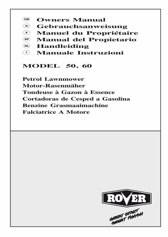
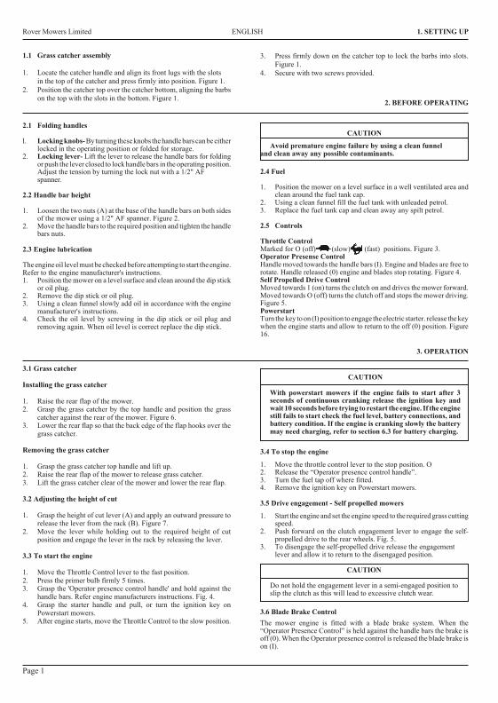
3. Press firmly down on the catcher top to lock the barbs into slots.Figure 1.
4. Secure with two screws provided.
2. BEFORE OPERATING
2.1 Folding handles
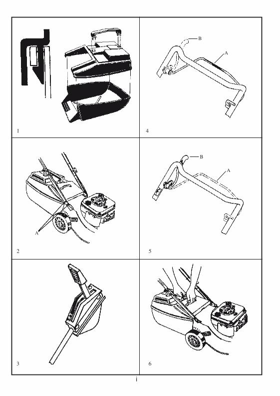
l. Locking knobs- By turning these knobs the handle bars can be eitherlocked in the operating position or folded for storage.
2. Locking lever- Lift the lever to release the handle bars for foldingor push the lever closed to lock handle bars in the operating position.Adjust the tension by turning the lock nut with a 1/2" AFspanner.
2.2 Handle bar height
1. Loosen the two nuts (A) at the base of the handle bars on both sidesof the mower using a 1/2" AF spanner. Figure 2.
2. Move the handle bars to the required position and tighten the handlebars nuts.
2.3 Engine lubrication
The engine oil level must be checked before attempting to start the engine.Refer to the engine manufacturer's instructions.1. Position the mower on a level surface and clean around the dip stick
or oil plug.2. Remove the dip stick or oil plug.3. Using a clean funnel slowly add oil in accordance with the engine
manufacturer's instructions.4. Check the oil level by screwing in the dip stick or oil plug and
removing again. When oil level is correct replace the dip stick.
CAUTION
Avoid premature engine failure by using a clean funneland clean away any possible contaminants.
2.4 Fuel
1. Position the mower on a level surface in a well ventilated area andclean around the fuel tank cap.
2. Using a clean funnel fill the fuel tank with unleaded petrol.3. Replace the fuel tank cap and clean away any spilt petrol.
2.5 Controls
Throttle ControlMarked for O (off) (slow) (fast) positions. Figure 3.Operator Presense ControlHandle moved towards the handle bars (I). Engine and blades are free torotate. Handle released (0) engine and blades stop rotating. Figure 4.Self Propelled Drive ControlMoved towards 1 (on) turns the clutch on and drives the mower forward.Moved towards O (off) turns the clutch off and stops the mower driving.Figure 5.PowerstartTurn the key to on (I) position to engage the electric starter. release the keywhen the engine starts and allow to return to the off (0) position. Figure16.
3.1 Grass catcher
Installing the grass catcher
1. Raise the rear flap of the mower.2. Grasp the grass catcher by the top handle and position the grass
catcher against the rear of the mower. Figure 6.3. Lower the rear flap so that the back edge of the flap hooks over the
grass catcher.
Removing the grass catcher
1. Grasp the grass catcher top handle and lift up.2. Raise the rear flap of the mower to release grass catcher.3. Lift the grass catcher clear of the mower and lower the rear flap.
3.2 Adjusting the height of cut
1. Grasp the height of cut lever (A) and apply an outward pressure torelease the lever from the rack (B). Figure 7.
2. Move the lever while holding out to the required height of cutposition and engage the lever in the rack by releasing the lever.
3.3 To start the engine
1. Move the Throttle Control lever to the fast position.2. Press the primer bulb firmly 5 times.3. Grasp the 'Operator presence control handle' and hold against the
handle bars. Refer engine manufacturers instructions. Fig. 4.4. Grasp the starter handle and pull, or turn the ignition key on
Powerstart mowers.5. After engine starts, move the Throttle Control to the slow position.
CAUTION
With powerstart mowers if the engine fails to start after 3seconds of continuous cranking release the ignition key andwait 10 seconds before trying to restart the engine. If the enginestill fails to start check the fuel level, battery connections, andbattery condition. If the engine is cranking slowly the batterymay need charging, refer to section 6.3 for battery charging.
3.4 To stop the engine
1. Move the throttle control lever to the stop position. O2. Release the “Operator presence control handle”.3. Turn the fuel tap off where fitted.4. Remove the ignition key on Powerstart mowers.
3.5 Drive engagement - Self propelled mowers
1. Start the engine and set the engine speed to the required grass cuttingspeed.
2. Push forward on the clutch engagement lever to engage the self-propelled drive to the rear wheels. Fig. 5.
3. To disengage the self-propelled drive release the engagementlever and allow it to return to the disengaged position.
CAUTION
Do not hold the engagement lever in a semi-engaged position toslip the clutch as this will lead to excessive clutch wear.
3.6 Blade Brake ControlThe mower engine is fitted with a blade brake system. When the“Operator Presence Control” is held against the handle bars the brake isoff (0). When the Operator presence control is released the blade brake ison (I).
1.1 Grass catcher assembly
1. Locate the catcher handle and align its front lugs with the slotsin the top of the catcher and press firmly into position. Figure 1.
2. Position the catcher top over the catcher bottom, aligning the barbson the top with the slots in the bottom. Figure 1.
3. OPERATION
Page 1
Rover Mowers Limited 7. SPARE PARTS
7.2 Handle bar spare parts
1 A03802 Handle bar-2 A03317 Lower handle bar3 A03583 Throttle cable- Mod. 503 A03326 Throttle cable- Mod. 604 A10016 Throttle control assembly5 A02849 Lock handle6 A03307 Draw bolt7 A03500 Cable clip8 A03518 Plug spanner9 A10144 Grass catcher assembly10 A03324 Mesh11 A03447 Handle12 A02260 Roll pin- 1/4" x 3/4"13 A02028 Setscrew- 5/16" x 5/8" unc.W/Face.
14 A04045 Flanged nut- 5/16" unc.15 A02223 Nyloc nut- 5/16" unc.16 A10523 Bale assembly CE17 A10524 Bale assembly CE18 A10503 Handle assembly CE19 A03739 Handle grip CE20 A02521 Spacer CE21 A03722 Brake cable- mod. 50,6022 A03733 Rope stop CE23 A02235 Nyloc nut- 1/4" unc.24 A04083 Screw - 10 x 19mm Pan Head252627 A03622 Decal
PAGE 7
Page 3
6.1 Battery removal
1. Remove the two retaining screws from each side of the batterysupport box and remove the front cover.
2. Remove the battery from the support box and simultaneouslydisconnect the wiring loom from the battery terminals.
6.2 Battery installation
1. Connect the mower wiring loom to the battery with the red leadattached to the positive (+) terminal of the battery and the black leadto the negative (-) terminal of the battery.
2. Fit the two rubber blocks to each end of the battery and place thebattery complete with the rubber blocks into the battery support boxwith the battery terminals closest to the centre of the mower.
3. Refit the battery support box front cover and retain with the twoscrews.
6.3 Battery charging
A new battery when supplied with the mower may not be fullycharged to maximum capacity. The battery should have an initialcharging period of 10 to 16 hours. To charge the battery it must beremoved from the mower first.
CAUTION
Use only an approved battery charger supplied by the mowerdealer which has been designed for use with this battery.
1. Connect the battery charger to the battery with thered lead (positive) to the positive (+) terminal of thebattery and the black (negative) lead to the negative(-) terminal of the battery.
2. Connect the battery charger to a suitable mainspower outlet and switch on.
3. When charging is complete after 10 to 16 hours, switch off the poweroutlet and disconnect the battery charger from the power outlet.
4. Disconnect the battery charger leads from the battery and refit thebattery to the mower.
6.4 Care and handling
1. Do not disassemble the battery, as it’s strong acid electrolyte mayburn your skin or clothes.
2. Do not short out the battery terminals, as this may burn the terminalsand cause damage to the equipment.
3. Do not incinerate the battery to depose of them.The battery may explode if exposed to fire.
4. Clean the battery with a dry cloth only, never use oil, petrol, thinnersor any other petrochemical.
5. Handle the battery with care. If the battery is dropped and the caseis damaged the acid electrolyte (sulphuric acid) may leak out. Wipeup leaking acid with a cloth and neutralise acid with an alkalinesolution.
6. In the event of electrolyte coming into contact with the skin,immediately flush with water and seek medical attention.
5.5 Clutch lining inspection
1. Remove the spark plug lead.2. Remove the cover plate as explained in section 5.1 “Drive chain
lubrication”.3. Check the thickness of the friction material. Figure 13. If thickness
of the friction material is less than 1mm the clutch plate should bereplaced by an authorised Rover Mowers Limited Dealer.
5.6 Drive pawl lubrication
1. Remove the spark plug lead.2. Support the rear wheels off the ground.3. Remove the rear drive wheel cap (a) and the wheel plug (b). Figure
14.4. Rotate the drive wheel to align the drive pinion with the wheel plug
hole.
5. Lubricate the slot at the centre of the drive pinion (d). Figure 15.6. Replace the wheel plug and wheel cap.7. Replace the spark plug lead.
5.7 Drive wheel cleaning
1. Remove the spark plug lead.2. Support the rear wheels off the ground and remove the wheel cap.3. Remove the ratchet plate (c) retaining the wheel to the axle.
Figure 15.4. Remove the wheel from the axle and clean the inside of the wheel
hub.5. Replace the wheel and retain using a new ratchet plate.6. Replace the wheel plug and wheel cap.7. Replace the spark plug lead.
6. MAINTENANCE - Powerstart Mowers
Rover Mowers Limited ENGLISH 5. MAINTENANCE - Self propelled mowers Rover Mowers Limited ITALIANO 5. MANUTENDIONE
Pagina 3
5.5 Ispezione rivestimento frizione
1. Staccare il cavetto dalla candela.
2. Rimuovere la piastra di ricoprimento come spiegato in
sezione 5.1 “Lubrificazione catena trasmissione”.
3. Controllare lo spessore del rivestimento della frizione.
Figura 13. Se tale spessore e’ inferiore a 1 mm il piatto
frizione dovrebbe essere sostituito, consigliabilmente presso
il rivenditore autorizzato della Rover Mowers Limited.
5.6 Lubrificazione ingranaggio trasmissione
1. Staccare il cavetto dalla candela.
2. Rialzare da terra con un sostegno le ruote posteriori.
3. Levare il copri perno (a) e il perno (b) della ruota motrice.
Figura 14.
4. Girare la ruota motrice in modo da allineare il pignone di
trasmissione con il foro del perno della ruota.
5. Lubrificare la fessura al centro del pignone di trasmissione
(d). Figura 14.
6. Rimettere a posto il perno ed il copriperno della ruota.
7. Riattaccare il cavetto della candela.
5.7 Pulizia ruota motrice
1. Staccare il cavetto della candela.
2. Rialzare da terra le ruote posteriori e levare il copri perno
della ruota.
3. Togliere la piastrina d’arresto (c) che ferma la ruota all’asse.
Figura 15.
4. Levare la ruota dall’asse e pulirne il mozzo.
5. Nel rimettere la ruota a posto usare una piastrina d’arresto
nuova.
6. Rimettere a posto il perno e il copriruota.
7. Riattaccare il cavetto alla candela.
6.1 Rimozione batteria
1. Svitare le due viti di ritegno ai due lati della scatola
portabatteria e levarne il lato anteriore.
2. Togliere la batteria dalla scatola e nel medesimo tempo
staccare i fili dai morsetti della batteria.
6.2 Installazione batteria
1. Collegare i cavi elettrici della falciatrice alla batteria, con il
cavo rosso collegato al morsetto positivo (+) della batteria
e il cavo nero al morsetto negativo (-) della batteria.
2. Mettere i 2 pezzi di gomma ai lati estremi della batteria e
sistemare la batteria con i pezzi di gomma nella scatola
portabatteria con i morsetti in posizione piu’ vicina al centro
della falciatrice.
3. Rimettere a posto il lato anteriore della scatola portabatteria
e fissarlo con le due viti.
6.3 Caricamento batteria
Una batteria nuova, fornita insieme alla falciatrice potrebbe
alle volte non essere carica alla sua capacita’ massima.
Normalmente la batteria dovrebbe avere un periodo di carica
da 10 a 16 ore. Per caricare la batteria bisogna prima levarla
dalla falciatrice.
AVVERTENZA
Usare solo un caricabatteria approvato dalla
fabbrica e fornito dal distributore della falciatrice
perche’ si tratta di un prodotto appositamente
studiato per questo tipo di batteria.
1. Collegare il caricabatteria con la batteria: il cavo rosso
(positivo) collegato al morsetto positivo (+) della batteria ed
il cavo nero negativo al morsetto negativo (-) della batteria.
2. Collegare il caricabatteria con una presa elettrica adatta e
accendere l’interruttore.
3. Quando, dopo circa 10-16 ore si e’ completata la carica,
spegnere l’interruttore della presa elettrica e staccare la
spina del caricabatteria dalla presa elettrica.
4. Staccare i cavi del caricabatteria dalla batteria e risistemare
la batteria nel portabatteria della falciatrice.
6.4 Cura e uso
1. Non smontare la batteria in quanto l’acido dell’elettrolite
potrebbe bruciare la pelle o gli indumenti.
2. Non mettere in corto circuito i morsetti della batteria, in
quanto cio’ potrebbe bruciare i morsetti stessi e causare
danni all’equipaggiamento elettrico.
3. Non mettere la batteria nell’incineratore, nell’intento di
disfarsene. La batteria puo’ esplodere se esposta al fuoco.
4. Pulire la batteria solo con panni asciutti, non usar mai olio,
benzina, solventi o qualsiasi altro prodotto petrolchimico.
5. Maneggiare con cura la batteria. Se si fa cadere la batteria
e il contenitore si e’ danneggiato puo’ uscirne fuori dell’acido
dell’elettrolite (acido solforico). Pulire bene l’acido con un
panno e neutralizzare l’acido con una soluzione alcalina.
6. Nel caso in cui tale elettrolite venga in contatto con la pelle,
lavare subito con acqua e richiedere assistenza medica.
6. MANUTENDIONE FALCIATRICI ADIGNIZIONEELECTRICA
3632 Steel Export.PMD 11/19/2002, 2:46 PM8
Rover Mowers LimitedITALIANO 4. MANUTENZIONE GENERALE
Pagina 2
4.1Filtro aria motore
Per istruzioni dettagliate sulla pulizia del filtro si prega riferirsi almanuale rilasciato dalla fabbrica del motore.L’elemento del filtro aria del motore deve essere pulito dopo ogni 25 oredi falciatura normale. Se pero’ si e’ falciato in condizioni polverosel’elemento dovra’ essere pulito piu’ frequentemente.
4.2Filtro aria tubo aspirazione
L’elemento del filtro aria dell’aspiratore deve essere pulito dopo ogni50 ore di falciatura normale. Se pero’ si e’ falciato in condizionipolverose l’elemento dovra’ essere pulito piu’ frequentemente.
1.Staccare il tubo aspiratore dal portaelemento.2.Staccare il coperchietto del portaelemento.3.Rimuovere l’elemento filtro e batterlo gentilmente su una superfice
piatta per rimuoverne la polvere.4.Rimettere a posto l’elemento e rimettere il coperchietto sul porta
elemento.5.Rimettere a posto il tubo aspiratore alla base del portaelemento.
Pregasi notare che i motori "Quantum" con tubo di respirazioned'aria lontano, non sono dotati di filtro dell'aria. Notare ancheche il filtro dell'aria in questo modello è messo sopra il motore.
AVVERTENZA
Non far entrare polvere nel tubo aspiratore aria per nonprovocare danni al motore. Controllare regolarmente lecondizioni del tubo aspiratore aria e sostituirlo sedanneggiato.
4.3Candela
Per ottenerne i migliori risultati levare la candela e controllarne lecondizioni ogni 25 ore d’uso.
1.Fermare il motore e staccare il cavetto dalla candela.2.Pulire intorno alla candela e levare la candela.3.Se occorre una nuova candela usare una Champion RJ19LM o
equivalente e regolare la distanza dell’elettrodo tra 0.7 e 0.8 mm.4.Riavvitare la candela nel motore e stringere fino a 20 NM.
AVVERTENZA
Non stringere troppo la candela per non causare danni almotore.
4.4Apparato taglio
1.Staccare il cavetto dalla candela2.Spostare la leva d’altezza taglio nella posizione piu’ alta.3.Muovere la falciatrice in modo da avere la candela nella parte
superiore.4.Ispezionare l’apparato taglio e vedere se ci sono danni o logorii.5.Controllare i bulloni che fissano il disco. Stringere il bullone al
centro fino a 48 NM e i 3 bulloni concentrici fino a 14 NM.6.Riportare la falciatrice in posizione normale e riattaccare il cavetto
alla candela.
AVVERTENZA
Staccare il cavetto dalla candela prima di lavoraresull’apparato taglio.
4.5Cambio lame
1.Staccare il cavetto dalla candela.2.Mettere la falciatrice in posizione di taglio alto.3.Alzare lo sportello posteriore nelle falciatrici a raccoglitore posteriore
e tenerlo aperto con l’apposito sostegno cosi’ da avere liberoaccesso alle lame. Alzare le falciatrici utilitarie in modo da averela candela in alto.
4.Togliere le lame, i bulloni di ritegno, i dadi e le rondelle e scartareil tutto. Lasciare solo le piastre ‘D’.
5.Mettere le lame nuove, i bulloni, le rondelle e i dadi in gruppicompleti per mantenere l’equilibrio. Figura 8.
6.Stringere i dadi delle lame fino a 16 NM. Controllare che le lamesi possano muovere liberamente quando i loro dadi sono intensione.
7.Rimuovere il sostegno dello sportello, riabbassare l’altezza taglioe riattaccare il cavetto alla candela.
4.6Controllo accelleratore
Ogni 25 ore di falciatura lubrificare la leva di controllo accelleratore conun po’ d’olio leggero.
5. MANUTENZIONE FALCIATRICI SEMOVENTI
5.1Lubrificazione catena trasmissione
1.Staccare il cavetto dalla candela.2.Levare le viti (a) della piastra di ricoprimento e sollevarla (b).
Figura 9.3.Alzare e tenere alzate con un sostegno le ruote posteriori in modo
che si possa girare liberamente la trasmissione.4.Lubrificare con olio SAE 30 la catena di trasmissione al punto (a)
mentre si fa ruotare la catena stessa. Figura 10.5.Rimettere a posto la piastra e fissarla con le viti.6.Riattaccare il cavetto alla candela.
5.2Regolazione catena trasmissione.
Catena tramissione anteriore1.Staccare il cavetto dalla candela.2.Rimuovere la piastra di ricoprimento.3.Allentare il bullone del tirante (b) della catena e muovere il tirante
fino a dargli 3 mm di deviazione rispetto alla catena di trasmissione.Figura 10.
4.Stringere il bullone del tirante e far girare le ruote motrici percontrollare se nella catena di trasmissione ci sono punti troppo tesi.
5.Rimettere a posto la piastra di ricoprimento.Catena trasmissione posteriore1.Staccare il cavetto dalla candela.2.Allentare the il dado (c) del tirante della catena di trasmissione
posteriore e farlo scorrere verso l’alto in modo da tendere la catenadi trasmissione posteriore. Figura 9.
3.Stringere il dado del tirante della catena di trasmissione posteriore
e ruotare le ruote motrici per controllare se ci sono dei punti troppotesi.
4.Riattaccare il cavetto alla candela.
5.3Ispezione catena trasmissione posteriore
1.Staccare il cavetto dalla candela.2.Svitare le viti che fissano la piastra di ricoprimento dell’albero di
trasmissione (a) e levare la piastra stessa (b). Figura 11.3.Svitare le viti di ritegno del parasassi (c) e levare il parasassi stesso.
Figura 11.4.Svitare i dadi (d) del paracatena e far scivolar via il paracatena
stesso. Figura 12.5.Ispezionare la catena di trasmissione e l’ingranaggio dell’asse e, se
trovato eccessivamente consumato, sostituirlo.6.Rimettere a posto il parasassi, il paracatena e la piastra dell’albero
di trasmissione.7.Riattaccare il cavetto alla candela.
5.4Regolazione frizione
1.Staccare il cavetto dalla candela.2.Allentare il dado di fissaggio (a) e girare il registro (b) in senso
orario fino a che la frizione faccia attrito. Figura 13.3.Rigirare indietro in senso antiorario il registro per 2 o 3 giri e
stringere il dado di fissaggio.4.Riattaccare il cavetto alla candela.
Rover Mowers LimitedDEUTSCH VORWORT
Verehrter Kunde,Wir bedanken uns, daß Sie ein Rover Produkt gekauft haben. Alle Rover-Rasenmäher sind entworfen und konstruiert, optimalesGrasschneiden unter normalen Grasschneideverhältnissen zu gewährleisten.
Diese Gebrauchsanweisung erklärt die Inbetriebnahme und Wartung des Rover Mähers. Beachten Sie bitte vor Inbetriebnahme die Hinweisein der Gebrauchsanweisung.
Sollte etwas unklar sein, verständigen Sie bitte Rover Mowers Limited oder einen ortszuständigen Beauftragten des Rover Kundendienstes.
Rover Mowers Limited behält sich das Recht vor, Änderungen und Verbesserungen zu jeder Zeit, ohne Ankündigung und unverbindlich,an ihrem Produkt vorzunehmen. Die Firma behält auch das Recht vor, die Herstellung irgendwelchen Produktes nach eigenem Ermessenzu jeder Zeit einzustellen.
Um besondere Information zu betonen, werden die Wörter VORSICHT und ACHTUNG benützt.
VORSICHT
Sorgen Sie für die Sicherheit des Bedieners und Dritten imArbeitsbereich des Gerätes. Sicherheitsmaßnahmen müssenbeachtet werden, um Unfälle zu verhindern.
INHALT........................................................................SEITE
Vorwort................................................................................iii
Sicherheitshinweise.................................................................iv
1.Montage.............................................................................11.1Grasfangvorrichtung................................................1
2.Vor Inbetriebnahme...........................................................12.1Klappgriffbügel.......................................................12.2Griffhöhe.................................................................12.3Ölen des Motors.......................................................12.4Benzin......................................................................12.5Bedienung................................................................1
3.Inbetriebnahme..................................................................13.1Grasfangvorrichtung................................................13.2Schnitthöhe einstellen..............................................13.3Anlassen des Motors................................................13.4Abstellen des Motors...............................................13.5Selbstangetriebene Mäher........................................13.6Messerbremeuug......................................................1
4.Allgemeine Wartung.........................................................24.1Motorluftreiniger.....................................................24.2Schnorchelluftfiten..................................................24.3Zündkerze................................................................24.4Schneidwerkzeug.....................................................24.5Messerwechsel.........................................................24.6Gashebelkontrolle....................................................2
5.Wartung für selbstangetriebene Mäher ............................25.1Ölen der Antriebskette.............................................25.2Einstellung der Antriebskette.................................25.3Kontrolle der hinteren Antriebskette.......................25.4Einstellung der Kupplung........................................25.5Kontrolle des Kupplungsbelages.............................35.6Ölen der Antriebssperrklinke...................................35.7Reinigung des Antriebsrades...................................4
ACHTUNG
Folgen Sie diesen Hinweisen, um Schaden am Mäher undeventuelle Ungültigkeit der Garantie zu vermeiden.
6.Wartung für Powerstart Mäher6.1Entfernung der Batterie...........................................36.2Einbau der Batterie..................................................36.3Batterieaufladung.....................................................36.4Pflege und Umgang.................................................3
7.Technische Daten............................................................. 47.1Bescheinigung der Übereinstimmung..................4,5
8.Ersatzteile..........................................................................68.1Serie 85000, 86000, 96000 Mäher...........................68.2Serie 85000, 86000, 96000 Griffbügel....................78.3Selbstangetriebener Mäher......................................88.4Powerstart Mäher.....................................................9
ABBILDUNGEN............................................................SEITE
Abb. 1.Grasfangvorrichtung...............................................iAbb. 2.Griffhöhe Einstellung.............................................iAbb. 3.Gasmarkierung.......................................................iAbb. 4.Bedieneranwesenheitakontrolle.............................iAbb. 5.Selbstantriebmarkierung........................................iAbb. 6.Einhängen der Fangvorrichtung.............................iAbb. 7.Schnitthöhe Einstellung.........................................iAbb. 8.Messerbolzenmontage............................................iAbb. 9.Antriebsketten Abdeckplatte.................................iiAbb. 10.Antriebsketten.......................................................iiAbb. 11.Antriebswellen Abdeckplatte................................iiAbb.12.Steinschutzvorrichtung..........................................iiAbb.13.Kupplungeinstellung.............................................iiAbb.14.Antriebsrad............................................................iiAbb.15.Antriebsritzel.........................................................iiAbb.16.Powerstart bedienung.....................................ii
iii
Rover Mowers LimitedITALIANO SICUREZZA
iv
ISTRUZIONI SULLA SICUREZZA
1.Come addestrarsi
a.Leggere attentamente le istruzioni. Familiarizzarsi con i comandiper il giusto uso della macchina.
b.Non permettere mai ai bambini o a persone non al corrente conqueste istruzioni di usare la falciatrice. Tenere presente che cipossono essere delle leggi locali che riguardano l’eta’ minimadell’operatore della falciatrice.
c.Non usare mai la falciatrice mentre ci sono bambini, persone, oanche animali di casa nelle vicinanze.
d.Tenere presente che l’operatore o utente e’ ritenuto responsabiledegli incidenti o dei rischi o pericoli causati a terzi o a proprieta’di terzi.
2.Preparativi
a.Ricordarsi di vestire calzature pesanti e pantaloni lunghi quando siusa la falciatrice. Non si deve usare la falciatrice se si e’ a piedi nudio si calzano sandali.
b.Ispezionare bene l’area da falciare e togliere tutti i sassi, bastoncini,fili metallici, ossa ed altri oggetti estranei.
c.Attenzione - La benzina e’ molto infiammabile
Usare le seguenti precauzioni:i.Tenere il carburante negli appositi contenitori.ii.Fare il pieni del serbatoio all’aperto e non fumare mentre sifa il pieno.iii.Fare il pieno prima di accendere il motore. Non togliere il
tappo del serbatoio o aggiungere benzina con il motore inmoto o quando il motore e’ ancora caldo.
iv. Se si e’ sparsa della benzina non accendere il motore; allontanareinvece la falciatrice dall’area bagnata di benzina ed evitare di crearescintille, fino a quando la benzina si sia evaporata.v. Rimettere al suo posto e stringere bene sia il tappo del serbatoioche quello del contenitore.
d.Sostituire i silenziatori difettosi.e.Prima di iniziarne l’uso ispezionare sempre le lame, i bulloni delle
lame e tutto l’apparato da taglio ed accertarsi che non siano logoratio danneggiati. Se ci sono lame danneggiate o logorate sostituire lelame al completo per mantenere l’equilibrio.
f.Nelle falciatrici multilame fare attenzione a non far torcere unalama perche’ cio’ puo’ causare la torcitura di altre lame.
3. Messa in funzione
a.Non mettere in moto il motore in uno spazio ristretto dove il fumodi scappamento con gas ossido di carbonio possa addensarsi.
b.Usare la falciatrice solo di giorno oppure con luce artificialeintensa.
c.Evitare se possibile di usare la falciatrice su erba bagnata.d.Sui pendii stare attenti a dove mettere i piedi.e.Camminare, non correre mai.f.Usando falciatrici semoventi, falciare i pendii trasversalmente,
mai andando in giu’ o in su’.g.Stare molto attenti nei cambiamenti di direzione sui pendii.h.Non falciare pendii troppo ripidi.i.Esercitare la massima precauzione nelle inversioni di marcia o nel
tirare la falciatrice verso se stessi.j.Assicurarsi che la lama o le lame siano fermate, se si deve alzare
la falciatrice per portarla su superfici non erbose oppure verso odall’area che deve essere falciata.
k.Non usare mai la falciatrice che abbia i pannelli di protezione o iparaurti difettosi, oppure non abbia perfettamente a posto quegliapparati di sicurezza come i deflettori o/e i raccoglitori d’erba.
l.Non cambiare la posizione di registrazione del regolatore delmotore e non sovraccellerare il motore.
m.Liberare tutte le lame e staccare le frizioni di trasmissione primadi accendere il motore.
n.Accendere il motore o mettere in funzione la falciatrice con moltaprecauzione, seguendo le istruzioni e tenendo i piedi ben distantidalle lame.
o.Non alzare la falciatrice quando si deve metterla in moto oaccendere il motore. A meno che la falciatrice debba essere alzataper essere messa in moto: nel qual caso non deve essere alzata piu’del necessario e soltanto dalla parte piu’ lontana dall’operatore.
p.Non accendere il motore stando davanti allo scarico erba.q.Non mettere le mani o i piedi vicini o sotto le parti ruotanti. Stare
sempre lontani dall’apertura dello scarico.r.Non sollevare o trasportare mai una falciatrice con motore acceso.s.Spegnere il motore e staccare il cavetto dalla candela:
i.Prima di levare delle ostruzioni o sbloccare lo scarico.ii.Prima di controllare, pulire, od eseguire lavori sulla falciatrice.iii.Dopo aver incontrato un oggetto estraneo. Ispezionare la
falciatrice per accertarsi dei danni. Riparare i danni prima diricominciare a falciare.
iv.Se la falciatrice comincia a vibrare in maniera anomala,controllare immediatamente.
t.Spegnere il motore:i. Ogni volta che bisogna allontanarsi dalla falciatrice.ii. Prima di aggiungere o fare il pieno di benzina.
u.Ridurre l’accellerazione durante i periodi di corsa a vuoto delmotore e, se il motore possiede una valvola di chiusura, chiudereil flusso del carburante alla conclusione della falciatura.
4. Manutenzione e immagazzinaggio.
a.Assicurarsi che tutti i bulloni, viti e dadi siano stretti, in modo chetutto l’apparato sia in condizioni d’uso sicure.
b.Non mettere o lasciare la falciatrice con del carburante nelserbatoio in un posto in cui i vapori di benzina possano raggiungeredelle fiamme vive o delle scintille.
c.Far raffreddare il motore prima di mettere la falciatrice nel suoripostiglio.
d.Allo scopo di ridurre il rischio d’incendio, levare erba, foglie oingrassaggio superfluo dalle superfici vicine al motore, silenziatore,batteria e serbatoio.
e.Ispezionare spesso il raccoglitore erba per vedere se ci sonodeterioramenti o logorii.
f.Per ragioni di sicurezza sostituire le parti o i pezzi danneggiati ologorati.
g.Se il serbatoio del carburante deve essere svuotato, svuotarloall’aperto.
Rover Mowers LimitedDEUTSCH 1. MONTAGE
Seite 1
1.1Grasfangvorrichtung
1.Den Griff der Fangvorrichtung lokallsleren und seine vordereHaltevorrichtungen und die sich oben auf der Fangvorrichtungbefindenden Spalten aufeinander ausrichten und fest elsetzen. Abb1.
2.Fest auf das Oberteil drücken um die Haken in die Spalteneinzusetzen. Abb.2.
3.Mit den zwei beigelegien befestigen.
2. VOR INBETRIEBNAHME
2.1Klappgriffbügel
1.Griffknaufen: Diese Knaufen drehen, um den Griffbügel inMähstellung zu setzen oder zum Zusammenklappen für Lagerung.
2.Schließhebel: Den Hebel anheben, um den Griffbügel zu lösen.Den Schließhebel nach unten drücken, um den Griffbügel inMähstellung zu setzen. Die Gegenmutter mit einem 1/2" AFSchlüssel anziehen, um die Spannung einzustellen.
2.2Griffhöhe
1.Die zwei Muttern (A) unten am Griffbügel auf beiden Seiten desMähers mit einem 1/2" AF Schlüssel lockern. Abb.2.
2.Den Griffbügel auf die gewünschte Höhe einstellen und dieMuttern fest anziehen.
2.3Ölen des Motors
Den Ölstand immer vor Anlassen des Motors prüfen. Lesen Sie dieAnweisungen des Motor Herstellers.
1.Den Mäher auf eine ebene Fläche stellen und um den Ölmeßstaboder den Ölstopfen herum reinigen.
2.Den Ölmeßstab oder Ölstopfen her ausziehen.3.Öl langsam miteinem Trichter vorschriftsmäßig einfüllen.4.Um den Ölstand zu prüfen, den Meßstab oder Ölstopfen wieder
einsetzen.
ACHTUNG
Um vorzeitigen Motorausfall zu vermeiden, einen sauberenTrichter benützen und mögliche Schmutzstoffe abwischen.
2.4Benzin
1.Den Mäher auf eine ebene Fläche, die gut belüftet ist, stellen undum den Tankdeckel herum abwischen.
2.Den Tank mit bleifreiem Benzin durch einen sauberen Trichterfüllen.
3.Den Deckel wieder aufsetzen und verschüttetes Benzin abwischen.
2.5 BodionungGasbedienungMarkierung A (aus) (langsam) (schnell). Bild. 3.BedieneranwesenheitakontrolleGiff in Richtung Giffbügel vorgestzt (I), Motor und messer rotieren frei,Griff gelôst (O) Motor und messer stoppen. Abb 4.SelbetantriebbetätgungEinstellung auf E (ein) aktiviert die Kupplung und den Motor vorwärts.Einstellung auf A (aus) schaltet die Kupplung aus und bringt den Mäherzum Stehen. Bild. 5.Powerstart KontrollenZundschlüssel auf Stelle an (I) drehen, um den Anlasser einzuschalten.Beim Anspringen des Motors den Schlück lassen. Abb14.
3. INBETRIEBNAHME
3.1Grasfangvorrichtung
Einhängen der Grasfangvorrichtung
1.Die hintere Klappe des Mähers anheben.2.Den Griff an der Fangvorrichtung festhalten und die Vorrichtung
hinten am Mäher anbringen. Abb.6.3.Die hintere Klappe senken, sodaß die Rückkante der Klappe sich
über die Fangvorrichtung einhakt
Abnehmen der Grasfangvorrichtung
1.Den oberen Griff an der Fangvorrichtung festhalten und anheben.2.Die hintere Klappe des Mähers mit der Grasfangvorrichtung
anheben, um diese loszulassen.3.Die Grasfangvorrichtung vom Mäher entfernen und die hintere
Klappe senken.
3.2Schnitthöhe einstellen
1.Den Hebel (A) nach außen ziehen, um ihn auszurasten.(B). Abb.7.2.Den Hebel nach außen gedrückt, auf die gewünschte Schnitthöhe
einstellen, dann den Hebel wieder einrasten lassen.
3.3Anlassen des Motors
1.Gashebel auf Schnell stellen.2.Den Ansaugbalg 5 Mal fest drücken.3.Den 'Bedieneranwesen heits kontrollegriff' festhatten und gegen
den Friffbügel drücken. Lesen Sie die Anweisungen des Motorherstellers.
4.Anlassergriff festhalten und ausziehen, oder beim PowerstartMäher den Zündschlüssel drehen.
5.Nach Anlauf des Motors Gashebel auf Landsam stellen.
ACHTUNG
Wenn der Motor beim Powerstart Mäher nach 3 Sekundenständigen Ankurbelns nicht anspringt, den Schlüssel loslassen, 10Sekunden abwarten, und den Motor dann erneut anlassen. Springtder Motor immer noch nicht an, den Benzinstand, Batterieanschlüsseund die Batterie überprüfen. Langsames Kurbeln weist auf eineschlechtgeladene Batterie. Die Batterie aufladen!Lesen Sie Abschnitt 6.3 unter Batterieaufladung.
3.4Abstellen des Motors
1.Den Gashebel auf Stop einstellen.2.Den Benzinhahn, wenn vorhanden, zudrehen.3.Beim Powerstart Mäher den Zündschlüssel abziehen.
3.5 Einstellung der Kupplung für selbstangetriebene Mäher
1.Den Motor anlassen und die Drehzahl auf die gewünschteSchneidgeschwindigkeit einstellen.
2.Kupplungshebel nach vorne drücken, um den Selbstantrieb derhinteren Räder einzusetzen.
3.Zum Aussetzen der Selbstantriebräder, den Kupplungshebelloslassen.
ACHTUNG
Der Kupplungshebel darf auf keinen Fall nur halb im Eingriffstehen, denn dies führt zu übermäßigem Verschleiß derKupplung.
3.6Messerbremsung
Der Mäher ist mit einer Messerbremsung ausgestattet. Wenn diebedienerkontrolle an die Lenkstabnge gedrückt wird, ist dieBremae ausgeschaltet. (A). Wenn die bedienerkontrolle gelöstwird, ist die Bremse eingeschaltet (E). Bild__
3632 Imposed PDF's.indd 418/05/2006 2:36:12 PM
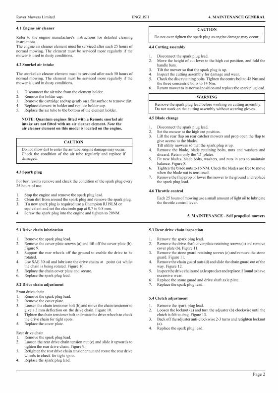
14
25
36
i
A
B
A
B
A
PAGE 11
Rover Mowers Limited
GBSelf propelled drive controlMoved towards (I) turns the clutch on and drives the mower forward.Moved towards (O) turns the clutch off and stops the mowerdriving
DSelbetantriebbetätgungEinstellung auf (I) aktiviert die Kupplung und den Motor vorwärs.Einstellung auf (I) schaltet die kupplung aus und bringt den Mäher zumStehen
FContrôle d'autotractionDéplacé vers (I) enclenche l'embrayage et fait avancer la tondeuse.Déplacé vers (O) décengage l'embrayage el empéche la tondeuse d'avancer
SPAutopropulsado marcas del controlMovido hacia (I) mueve el desembragador y pone a marcha el cortacesped.Movido hacia el (O) apaga el desembragador y para el cortacesped
NLRegulatuur bij relfverplaatsende machinesAls men de knop op (I) zet, is de koppeling ingeschakeld en de machinerijdt vooruit. Als de knop (O) zet, schakelt men de knoppeling uit en
de machine stopt.
ICamando trazione removente
Se mosso verso I (innestato) innesta la frizione e muove in avanti la
faiciatrice tosaerba. Se mosso verso O (disinnestato) disinnesta la
frizione e ferma la trazione della falciatrice tosaerba
GBOperator presense controlHandle moved towards the handle bars, engine and blades are free torotate. Handle released, engine and blades stop rotating
DBedieneranwesenheitakontrolleGiff in Richtung Giffbügel vorgestzt, motor und messer rotieren frei,Griff gelôst, Motor und messer stoppen
FContrôle par opérateurPoigée avancée vers les mancherons, moteur et lames peuvent tourner.Poignée relâchée, moteur arrêtent de tourner
SPOperador de las presencias controlesMango movido hacia manillas, motor y cuchillas estanlibres de hacervucltas. Mango disparado, motor y cuchillas paran de hacer vucltas
NLDodenmanskoop regulatuurknop die aangeeft dat de oparateuraanwezig isDe gasbedieningshendel geplaast in de richting van de hand grepen,de machine loopt en de messen draaien vrij. Gasbedieningshendel isafgezet, de machine stopt, en de messen draaicn neit meer
IComando presenza operatore(I) Manopola mossa verso barre manubrio, motere e lame in posizionelibers e rptanti. (O) manopola disimpegnata. Motre e lame fermi
GBThrottle controlMarked for off, slow and fast positions
DGasbedienungMarkierung aus, langsam sch schnell
FContrôle des gazMarque pour les positions arrêt, ralenti accéléré et
SPControl del acceleradorMarcado por apagado, despacio, rapido posiciones
NLGasknop regulatuurVoorzien van markteken uit, langzaam, snel tekening
IComandeSegno di poizione O staccato lento veloce
3632 Steel Export.PMD11/11/2002, 10:10 AM 2
Rover Mowers Limited7. SPARE PARTS
1A03802Upper handle bars-Mod 602A10016Throttle control assembly3A03581Throttle cable- Quantum4A03557Key start housing5A03560Key start switch6A07679Ignition key7A03741Wiring loom- Mod 60 CE8A03565Cable clamp9A03559Battery10A03558Battery block11A03556Battery support box12A03563Decal- caution13A02083Setscrew- 5/16" x 3/4" unc.hex.14 A02012Washer- 5/16" x 7/8" x 18g.flat15 A02223Nyloc nut- 5/16" unc.16 A02002Speed nut- 3/16" bsw.17 A02163Screw- 3/16" x 1/2" mush/head18 A04060Rivet- 73 AS 5-2
19A03610Foam block2021A10524Bale assembly- Mod 60 CE22A10503Handle assembly Mod.60- CE23A02521Spacer24A03739Handle grip- CE25A03732Cable clip- CE26A03733Rope stop- CE2728A02235Nyloc nut- 1/4" unc.29A04083Screw- 10 x 3/4 pan head3030A03722Brake cable- mod. 6031A03756Switch Plate
7.4 Powerstart spare parts - Series 85000, 86000
PAGE 9
Rover Mowers LimitedENGLISHPREFACE
WARNINGCAUTIONFollow these instructions to avoid mower damage andpossible loss of warranty
The safety of the user and others involved. Personal Injurymay result should this information be disregarded.
CONTENTSPAGE
Preface............................................................................iii
Safety Instructions..........................................................iv
1.Setting up...................................................................11.1Grass catcher assembly...................................1
2.Before operating........................................................12.1Folding handles...............................................12.2Handle bar height............................................12.3Engine lubrication...........................................12.4Fuel..................................................................12.5Controls...........................................................1
3.Operation...................................................................13.1Grass catcher...................................................13.2Adjusting the height of cut..............................13.3To start the engine...........................................13.4To stop the engine...........................................13.5Self propelled mowers.....................................13.6Blade brake control.........................................1
4.Maintenance - General..............................................24.1Engine air cleaner............................................24.2Snorkel air cleaner...........................................24.3Spark Plug.......................................................24.4Cutting assembly.............................................24.5Blade change...................................................24.6Throttle control................................................2
5.Maintenance - self propelled mowers........................25.1Drive chain lubrication....................................25.2Drive chain adjustment....................................25.3Rear drive chain inspection.............................35.4Clutch adjustment............................................35.5Clutch lining inspection..................................35.6Drive pawl lubrication.....................................35.7Drive Wheel Cleaning.....................................3
6.Maintenance powerstart mowers6.1Battery removal...............................................36.2Battery installation..........................................36.3Battery charging..............................................36.4Care and handling............................................3
7.Spare parts.................................................................67.1Series 85000, 86000, 96000 base....................67.2Series 85000, 86000, 96000 bars....................77.3Self-propelled..................................................87.4Powerstart........................................................9
ILLUSTRATIONS.................................................PAGE
Figure 1.Grass catcher assembly...............................iFigure 2.Handle bar height adjustment.....................iFigure 3.Throttle control markings...........................iFigure 4.Operator presence control...........................iFigure 5.Self propelled drive control........................iFigure 6.Grass catcher fitment..................................iFigure 7.Height adjustment......................................iiFigure 8.Blade bolt assembly...................................iiFigure 9.Drive chain cover plate..............................iiFigure 10.Drive chain.................................................iiFigure 11.Drive shaft cover........................................iiFigure 12.Stone cover................................................iiFigure 13.Clutch adjustment......................................iiFigure 14.Drive wheel................................................iiFigure 15.Drive pinion...............................................iiFigure 16.Powerstart control......................................ii
iii
Thank you for buying a Rover Product. All Rover Lawn mowers are designed and constructed to give optimum grass cuttingperformance under normal grass cutting conditions.
This manual covers the operation and maintenance of the Rover walk behind mower. Please read and understand this ownersmanual, before using the mower.If any point is unclear, contact Rover Mowers Limited or any authorised Rover Mower service dealer.
Rover Mowers Limited reserves the right to make changes of, and add improvements upon, its product at anytime, without noticeor obligation. The Company also reserves the right to discontinue manufacture of any product at its discretion at any time.
To emphasise special information, the words WARNING and CAUTION are used.
Rover Mowers Limited 7. SPARE PARTS
1 A03300 Base 12 A03510 Height adjustment rack 13 A03456 Rear Flap 14 A03325 Spring- rear flap 15 A03455 Handle- rear flap 16 A03126 Pivot bush 27 A10148 Conbar assembly 18 A02591 Conbar spring 19 A03515 Axle bracket- RH. 110 A03514 Axle bracket- LH. 111 A03516 Clamp bolt 212 A02051 Woodruff key 113 A01486 Disc boss 114 A00293 Disc assembly 115 A01716 Backplate 116 A03830 Blade- standard 416 A03930 Blade- Mulch N Catch17 A00673 Blade bolt kit 218 A10154 Disc bolt kit 119 A10140 Front axle assembly- professional 119 A10527 Front axle assembly- professional 120 A03450 Front axle bush 221 A03459 Wheel seal 422 A03320 Front wheel assembly 223 A03353 Wheel bearing 824 A03414 Wheel cap 425 A03306 Pivot rod 126 A03743 Decal- Warning 1
27 A03492 Decal- sound level 128 A03409 Nameplate 129 373109 Tension washer 430 A03092 Ratchet plate 431 S2501116 Ratchet plate 232 290112 Poprivet- 73 AS 6-4 blind 1033 A02127 Taptite- 3/8" - 16 HWH x 1" Ind.hex.W/H Duo. 334 * Decal- Model 135 A04052 Self tapping screw- 10 x 5/8" pan ph/head236 A03549 Cable clip 137 A03323 Plug chain slot- model 50 138 A010141 Rear axle assembly- model 50 139 A03313 Rear axle bush- model 50 240 A03250 Plastic handle 141 A10284 Height adj. lever assembly 142 A03336 Packing plate 143 A02066 Rivet 244 A03319 Rear wheel assembly 245 A03303 Grass deflector 146 A10381 Rear stoneguard- Mod. 50 146 A03604 Rear stoneguard- Mod. 60 147 A02071 Rivet- 73 SS 4-3 248 A02235 Nyloc nut- 1/4" unc. 249 A03472 Decal- turbothrust 150 A03927 Nose comb 151 A04108 Rivet 252 A04099 Washer- 3/16" x 3/4" 253 A04111 Screw 2
7.1 Series 85000, 86000 and 96000 base spare parts
PAGE 6
26
Rover Mowers Limited ENGLISH 4. MAINTENANCE GENERAL
5. MAINTENANCE - Self propelled mowers
5.1 Drive chain lubrication
1. Remove the spark plug lead.2. Remove the cover plate screws (a) and lift off the cover plate (b).
Figure 9.3. Support the rear wheels off the ground to enable the drive to be
rotated.4. Use SAE 30 oil and lubricate the drive chains at point (a) whilst
the chain is being rotated. Figure 10.5. Replace the chain cover plate and secure.6. Replace the spark plug lead.
5.2 Drive chain adjustment
Front drive chain1. Remove the spark plug lead.2. Remove the cover plate.3. Loosen the chain tensioner bolt (b) and move the chain tensioner to
give a 3 mm deflection on the drive chain. Figure 10.4. Tighten the chain tensioner bolt and rotate the drive wheels to check
the drive chain for tight spots.5. Replace the cover plate.
Rear drive chain1. Remove the spark plug lead.2. Loosen the rear drive chain tension nut (c) and slide it upwards to
tighten the rear drive chain. Figure 9.3. Retighten the rear drive chain tensioner nut and rotate the rear drive
wheels to check for tight spots.4. Replace the spark plug lead.
5.3 Rear drive chain inspection
1. Remove the spark plug lead.2. Remove the drive shaft cover plate retaining screws (a) and remove
cover plate (b). Figure 11.3. Remove the stone guard retaining screws (c) and remove the stone
guard. Figure 11.4. Remove the chain guard nuts (d) and slide the chain guard out of the
way. Figure 12.5. Inspect the drive chain and axle sprocket and replace if found to have
excessive wear.6. Replace the stone guard and drive shaft axle plate.7. Replace the spark plug lead.
5.4 Clutch adjustment
1. Remove the spark plug lead.2. Loosen the locknut (a) and turn the adjuster (b) clockwise until the
clutch is felt to drag. Figure 13.3. Back off the adjuster anti-clockwise 2-3 turns and retighten locknut
(a).4. Replace the spark plug lead.
4.1 Engine air cleaner
Refer to the engine manufacture's instructions for detailed cleaninginstructions.The engine air cleaner element must be serviced after each 25 hours ofnormal mowing. The element must be serviced more regularly if themower is used in dusty conditions.
4.2 Snorkel air intake
The snorkel air cleaner element must be serviced after each 50 hours ofnormal mowing. The element must be serviced more regularly if themower is used in dusty conditions.
1. Disconnect the air tube from the element holder.2. Remove the holder cap.3. Remove the cartridge and tap gently on a flat surface to remove dirt.4. Replace element in holder and replace holder cap.5. Replace the air tube to the bottom of the element holder.
NOTE: Quantum engines fitted with a Remote snorkel airintake are not fitted with an air cleaner element. Note theair cleaner element on this model is located on the engine.
CAUTION
Do not allow dirt to enter the air tube, engine damage may occur.Check the condition of the air tube regularly and replace ifdamaged.
4.3 Spark plug
For best results remove and check the condition of the spark plug every25 hours of use.
1. Stop the engine and remove the spark plug lead.2. Clean dirt from around the spark plug and remove the spark plug.3. If a new spark plug is required use a Champion RJ19LM or
equivalent and set the electrode gap at 0.7 to 0.8 mm.4. Screw the spark plug into the engine and tighten to 20NM.
4.4 Cutting assembly
1. Disconnect the spark plug lead.2. Move the height of cut lever to the high cut position, and fold the
handle bars.3. Tilt the mower so that the spark plug is up.4. Inspect the cutting assembly for damage and wear.5. Check the disc retaining bolts. Tighten the centre bolt to 48 Nm.and
the three concentric bolts to 14 Nm.6. Return mower to its normal position and replace the spark plug lead.
WARNING
Remove the spark plug lead before working on cutting assembly.Do not work on the cutting assembly without wearing gloves.
4.5 Blade change
1. Disconnect the spark plug lead.2. Set the mower to the high cut position.3. Lift the rear flap on rear catcher mowers and prop open the flap to
give access to the blades.Tilt utility mowers so that the spark plug is up.
4. Remove the blade, blade retaining bolts, nuts and washers anddiscard. Retain only the ‘D’ plates.
5. Fit new blades, blade bolts, washers, and nuts in sets to maintainbalance. Figure 8.
6. Tighten the blade nuts to 16 NM. Check the blades are free to movewhen the blade nut is tensioned.
7. Remove the flap prop or lower the mower to the ground and replacethe spark plug lead.
4.6 Throttle control
Each 25 hours of mowing use a small amount of light oil to lubricatethe throttle control lever.
Page 2
CAUTION
Do not over tighten the spark plug as engine damage may occur.
Rover Mowers Limited 7. SPARE PARTS
PAGE 8
1 A02102 Washer- Avdel 7601/00102 A10177 Clutch lever3 A03365 Clutch cable4 A07822 Cable tie5 A03314 Rear axle support6 A03391 Stoneguard mount bracket7 A03383 Rear stoneguard- 960127 A10381 Rear stoneguard- 86012, 860408 A03393 Drive shaft cover9 A02090 Circlip- 1400/1210 A03373 Pawl retainer washer11 A03371 Drive pinion- RH12 A03372 Pawl13 A03361 Bearing- 6001 DDU14 A07675 Nylon bush15 A10172 Rear axle assembly16 A03366 Rear chain guard17 A03394 Felt seal18 A02069 Roll pin- 1/8" x 3/4"19 A03368 Rear drive shaft sprocket20 A03382 Dust seal21 A03353 Wheel bearing22 A03352 Geared wheel hub23 A03441 Washer plate
24 A03414 Wheel cap25 A03369 Drive shaft26 A03377 Rear drive chain27 A03364 Cable support bracket- RH28 A03367 Chain tensioner29 A03360 Clutch engagement bush30 A10171 Driver clutch plate31 A03358 Clutch spring32 A10170 Driven clutch plate33 A03359 Clutch support shaft34 A03550 Drive chain housing- LH35 A03363 Cable support bracket- LH36 A03370 Drive pinion- LH37 A04052 Self tapping screw- 10 x 5/8" pan ph/head38 A03552 Chain guard cover plate39 A03551 Drive chain housing- RH40 A03386 Felt seal41 A02070 Roll pin- 3/16" x 7/8"42 A03354 Sprocket PTO.43 A03376 Front drive chain44 A03375 Pivot rod45 A03250 Handle46 A02146 Setscrew- 1/4" x 3/4" unc.hex47 A02214 Setscrew- 1/4" x 5/8" unc.hex
48 A02078 Setscrew- 1/4" x 1/2" unc.hex49 A02081 Setscrew- 1/4" x 1-3/4" unc.hex50 A02235 Nyloc nut- 1/4" unc.51 S2491162 Nut- 1/4" unc.square pressed52 A02001 Nut- 1/4" unc.hex53 A03092 Washer- Avdel 7301/001654 A02030 Washer- 5/16" x 5/8" x 18g.flat55 A02209 Washer- 1/4" x 5/8" x 18g.flat56 A02044 Washer- 1/4" internal shakeproof57 S373109 Tension washer58 A10146 Wheel assembly59 S2501108 Washer- Avdel 7301/000860 A10284 Height adjustment lever assembly61 A02118 Rivet- 3/4" x 1/4" flat head62 A03336 Plate63 S3521047 Wheel plug64 A03470 Chain guide65 290112 Rivet- 73 AS 6-4 blind66 A03390 Clutch plate lining67 A03384 Tyre68 A10524 Bale assembly CE69 A10503 Handle assembly CE70 A03739 Handle grip CE71 A02521 Spacer CE72 A03604 Rear extension- Mod. 60
7.3 Self propelled spare parts
Rover Mowers Limited ENGLISH SAFETY INSTRUCTIONS
Safety Instructions1. Training
a. Read the instructions carefully. Be familiar with thecontrols and the proper use of the equipment.
b. Never allow children or people unfamiliar with theseinstructions to use the mower. Local regulations mayrestrict the age of the operator.
c. Never mow while people, especially children, or petsare nearby.
d. Keep in mind that the operator or user is responsiblefor accidents or hazards occurring to other people ortheir property.
2. Preparation
a. While mowing, always wear substantial footwear andlong trousers.Do not operate the equipment when barefoot orwearing open sandals.
b. Thoroughly inspect the area where the equipment isto be used and remove all stones, sticks, wires,bones and other foreign objects.
c. WARNING- Petrol is highly flammable.
Take the following precautions.i. Store fuel in containers specially designed for this
purpose.ii. Refuel outdoors only and do not smoke whilerefuelling.iii. Add fuel before starting the engine. Never remove
the cap of the fuel tank or add petrol while the engineis running or when the engine is hot.iv. If petrol is spilled, do not attempt to start theengine but move the machine away from the area ofspillage and avoid creating any source of ignitionuntil petrol vapours have dissipated.v. For reasons of safety the petrol tank and tank cap lock must be
replaced if damaged.d. Replace faulty silencers.e. Before using, always visually inspect to see that the
blades, blade bolts and cutter assembly are not worn ordamaged. Replace worn or damaged blades in sets topreserve balance.
f. On multibladed machines, take care as rotating oneblade can cause other blades to rotate.
3. Operation
a. Do not operate the engine in a confined space wheredangerous carbon monoxide fumes can collect.
b. Mow only in daylight or in good artificial light.c. Avoid operating the equipment in wet grass, where
feasible.d. Always be sure of your footing on slopes.e. Walk, never run.f. For wheeled rotary machines, mow across the face of
slopes, never up and down.g. Exercise extreme caution when changing direction on
slopes.
h. Do not mow excessively steep slopes.i. Use extreme caution when reversing or pulling the
mower towards you.j. Stop the blade(s) ,if the mower has to be tilted for
transportation when crossing surfaces other than grassand when transporting the mower to and from the areato be mowed.
k. Never operate the mower with defective guards orshields, or without safety devices, for example deflectorsand/or grass catchers in place.
l. Do not change the engine governor settings or overspeedthe engine.
m. Disengage all blade and drive clutches before startingthe engine.
n. Start the engine or switch on the mower carefullyaccording to instructions and with feet well awayfrom the blade(s).
o. Do not tilt when starting the engine or switching onthe motor, unless the mower has to be tilted forstarting. In this case, do not tilt it more than absolutelynecessary and lift only the part which is away from theoperator.
p. Do not start the engine when standing in front of thedischarge chute.
q. Do not put hands or feet near or under rotating parts.Keep clear of the discharge opening at all times.
r. Never pick up or carry a mower while the engine isrunning.
s. Stop the engine and disconnect the spark plug lead:i. Before clearing blockages or unclogging the chute.ii. Before checking, cleaning or working on the mower.iii. After striking a foreign object. Inspect the mower for
damage and make repairs before restarting andoperating the mower.
iv. If the mower starts to vibrate abnormally checkimmediately.
t. Stop the enginei. Whenever you leave the mower.ii. Before refuelling.
u. Reduce the throttle setting during engine run-out and ifthe engine is provided with a shut-off valve, turn off thefuel at the conclusion of mowing.
4. Maintenance and storage.
a. Keep all nuts, bolts, and screws tight to be sure theequipment is in safe working condition.
b. Never store the equipment with petrol in the tank insidea building where fumes may reach an open flame orspark.
c. Allow the engine to cool before storing in any enclosure.d. To reduce the fire hazard, keep the engine, silencer,
battery compartment and petrol storage area free ofgrass, leaves, or excessive grease.
e. Check the grass catcher frequently for wear ordeterioration.
f. Replace worn or damaged parts for safety.g. If the fuel tank has to be drained, do this outdoors.
iv
3632 Imposed PDF's.indd 3 18/05/2006 2:36:10 PM
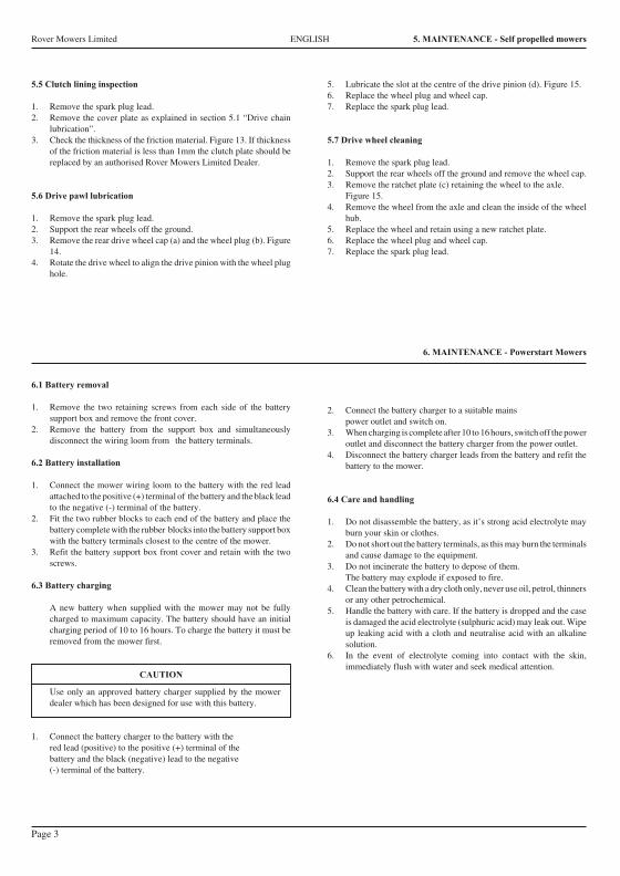
Rover Mowers Limited ENGLISH 1. SETTING UP
3. Press firmly down on the catcher top to lock the barbs into slots.Figure 1.
4. Secure with two screws provided.
2. BEFORE OPERATING
2.1 Folding handles
l. Locking knobs- By turning these knobs the handle bars can be eitherlocked in the operating position or folded for storage.
2. Locking lever- Lift the lever to release the handle bars for foldingor push the lever closed to lock handle bars in the operating position.Adjust the tension by turning the lock nut with a 1/2" AFspanner.
2.2 Handle bar height
1. Loosen the two nuts (A) at the base of the handle bars on both sidesof the mower using a 1/2" AF spanner. Figure 2.
2. Move the handle bars to the required position and tighten the handlebars nuts.
2.3 Engine lubrication
The engine oil level must be checked before attempting to start the engine.Refer to the engine manufacturer's instructions.1. Position the mower on a level surface and clean around the dip stick
or oil plug.2. Remove the dip stick or oil plug.3. Using a clean funnel slowly add oil in accordance with the engine
manufacturer's instructions.4. Check the oil level by screwing in the dip stick or oil plug and
removing again. When oil level is correct replace the dip stick.
CAUTION
Avoid premature engine failure by using a clean funneland clean away any possible contaminants.
2.4 Fuel
1. Position the mower on a level surface in a well ventilated area andclean around the fuel tank cap.
2. Using a clean funnel fill the fuel tank with unleaded petrol.3. Replace the fuel tank cap and clean away any spilt petrol.
2.5 Controls
Throttle ControlMarked for O (off) (slow) (fast) positions. Figure 3.Operator Presense ControlHandle moved towards the handle bars (I). Engine and blades are free torotate. Handle released (0) engine and blades stop rotating. Figure 4.Self Propelled Drive ControlMoved towards 1 (on) turns the clutch on and drives the mower forward.Moved towards O (off) turns the clutch off and stops the mower driving.Figure 5.PowerstartTurn the key to on (I) position to engage the electric starter. release the keywhen the engine starts and allow to return to the off (0) position. Figure16.
3.1 Grass catcher
Installing the grass catcher
1. Raise the rear flap of the mower.2. Grasp the grass catcher by the top handle and position the grass
catcher against the rear of the mower. Figure 6.3. Lower the rear flap so that the back edge of the flap hooks over the
grass catcher.
Removing the grass catcher
1. Grasp the grass catcher top handle and lift up.2. Raise the rear flap of the mower to release grass catcher.3. Lift the grass catcher clear of the mower and lower the rear flap.
3.2 Adjusting the height of cut
1. Grasp the height of cut lever (A) and apply an outward pressure torelease the lever from the rack (B). Figure 7.
2. Move the lever while holding out to the required height of cutposition and engage the lever in the rack by releasing the lever.
3.3 To start the engine
1. Move the Throttle Control lever to the fast position.2. Press the primer bulb firmly 5 times.3. Grasp the 'Operator presence control handle' and hold against the
handle bars. Refer engine manufacturers instructions. Fig. 4.4. Grasp the starter handle and pull, or turn the ignition key on
Powerstart mowers.5. After engine starts, move the Throttle Control to the slow position.
CAUTION
With powerstart mowers if the engine fails to start after 3seconds of continuous cranking release the ignition key andwait 10 seconds before trying to restart the engine. If the enginestill fails to start check the fuel level, battery connections, andbattery condition. If the engine is cranking slowly the batterymay need charging, refer to section 6.3 for battery charging.
3.4 To stop the engine
1. Move the throttle control lever to the stop position. O2. Release the “Operator presence control handle”.3. Turn the fuel tap off where fitted.4. Remove the ignition key on Powerstart mowers.
3.5 Drive engagement - Self propelled mowers
1. Start the engine and set the engine speed to the required grass cuttingspeed.
2. Push forward on the clutch engagement lever to engage the self-propelled drive to the rear wheels. Fig. 5.
3. To disengage the self-propelled drive release the engagementlever and allow it to return to the disengaged position.
CAUTION
Do not hold the engagement lever in a semi-engaged position toslip the clutch as this will lead to excessive clutch wear.
3.6 Blade Brake ControlThe mower engine is fitted with a blade brake system. When the“Operator Presence Control” is held against the handle bars the brake isoff (0). When the Operator presence control is released the blade brake ison (I).
1.1 Grass catcher assembly
1. Locate the catcher handle and align its front lugs with the slotsin the top of the catcher and press firmly into position. Figure 1.
2. Position the catcher top over the catcher bottom, aligning the barbson the top with the slots in the bottom. Figure 1.
3. OPERATION
Page 1
Rover Mowers Limited 7. SPARE PARTS
7.2 Handle bar spare parts
1 A03802 Handle bar-2 A03317 Lower handle bar3 A03583 Throttle cable- Mod. 503 A03326 Throttle cable- Mod. 604 A10016 Throttle control assembly5 A02849 Lock handle6 A03307 Draw bolt7 A03500 Cable clip8 A03518 Plug spanner9 A10144 Grass catcher assembly10 A03324 Mesh11 A03447 Handle12 A02260 Roll pin- 1/4" x 3/4"13 A02028 Setscrew- 5/16" x 5/8" unc.W/Face.
14 A04045 Flanged nut- 5/16" unc.15 A02223 Nyloc nut- 5/16" unc.16 A10523 Bale assembly CE17 A10524 Bale assembly CE18 A10503 Handle assembly CE19 A03739 Handle grip CE20 A02521 Spacer CE21 A03722 Brake cable- mod. 50,6022 A03733 Rope stop CE23 A02235 Nyloc nut- 1/4" unc.24 A04083 Screw - 10 x 19mm Pan Head252627 A03622 Decal
PAGE 7
Page 3
6.1 Battery removal
1. Remove the two retaining screws from each side of the batterysupport box and remove the front cover.
2. Remove the battery from the support box and simultaneouslydisconnect the wiring loom from the battery terminals.
6.2 Battery installation
1. Connect the mower wiring loom to the battery with the red leadattached to the positive (+) terminal of the battery and the black leadto the negative (-) terminal of the battery.
2. Fit the two rubber blocks to each end of the battery and place thebattery complete with the rubber blocks into the battery support boxwith the battery terminals closest to the centre of the mower.
3. Refit the battery support box front cover and retain with the twoscrews.
6.3 Battery charging
A new battery when supplied with the mower may not be fullycharged to maximum capacity. The battery should have an initialcharging period of 10 to 16 hours. To charge the battery it must beremoved from the mower first.
CAUTION
Use only an approved battery charger supplied by the mowerdealer which has been designed for use with this battery.
1. Connect the battery charger to the battery with thered lead (positive) to the positive (+) terminal of thebattery and the black (negative) lead to the negative(-) terminal of the battery.
2. Connect the battery charger to a suitable mainspower outlet and switch on.
3. When charging is complete after 10 to 16 hours, switch off the poweroutlet and disconnect the battery charger from the power outlet.
4. Disconnect the battery charger leads from the battery and refit thebattery to the mower.
6.4 Care and handling
1. Do not disassemble the battery, as it’s strong acid electrolyte mayburn your skin or clothes.
2. Do not short out the battery terminals, as this may burn the terminalsand cause damage to the equipment.
3. Do not incinerate the battery to depose of them.The battery may explode if exposed to fire.
4. Clean the battery with a dry cloth only, never use oil, petrol, thinnersor any other petrochemical.
5. Handle the battery with care. If the battery is dropped and the caseis damaged the acid electrolyte (sulphuric acid) may leak out. Wipeup leaking acid with a cloth and neutralise acid with an alkalinesolution.
6. In the event of electrolyte coming into contact with the skin,immediately flush with water and seek medical attention.
5.5 Clutch lining inspection
1. Remove the spark plug lead.2. Remove the cover plate as explained in section 5.1 “Drive chain
lubrication”.3. Check the thickness of the friction material. Figure 13. If thickness
of the friction material is less than 1mm the clutch plate should bereplaced by an authorised Rover Mowers Limited Dealer.
5.6 Drive pawl lubrication
1. Remove the spark plug lead.2. Support the rear wheels off the ground.3. Remove the rear drive wheel cap (a) and the wheel plug (b). Figure
14.4. Rotate the drive wheel to align the drive pinion with the wheel plug
hole.
5. Lubricate the slot at the centre of the drive pinion (d). Figure 15.6. Replace the wheel plug and wheel cap.7. Replace the spark plug lead.
5.7 Drive wheel cleaning
1. Remove the spark plug lead.2. Support the rear wheels off the ground and remove the wheel cap.3. Remove the ratchet plate (c) retaining the wheel to the axle.
Figure 15.4. Remove the wheel from the axle and clean the inside of the wheel
hub.5. Replace the wheel and retain using a new ratchet plate.6. Replace the wheel plug and wheel cap.7. Replace the spark plug lead.
6. MAINTENANCE - Powerstart Mowers
Rover Mowers Limited ENGLISH 5. MAINTENANCE - Self propelled mowers Rover Mowers Limited ITALIANO 5. MANUTENDIONE
Pagina 3
5.5 Ispezione rivestimento frizione
1. Staccare il cavetto dalla candela.
2. Rimuovere la piastra di ricoprimento come spiegato in
sezione 5.1 “Lubrificazione catena trasmissione”.
3. Controllare lo spessore del rivestimento della frizione.
Figura 13. Se tale spessore e’ inferiore a 1 mm il piatto
frizione dovrebbe essere sostituito, consigliabilmente presso
il rivenditore autorizzato della Rover Mowers Limited.
5.6 Lubrificazione ingranaggio trasmissione
1. Staccare il cavetto dalla candela.
2. Rialzare da terra con un sostegno le ruote posteriori.
3. Levare il copri perno (a) e il perno (b) della ruota motrice.
Figura 14.
4. Girare la ruota motrice in modo da allineare il pignone di
trasmissione con il foro del perno della ruota.
5. Lubrificare la fessura al centro del pignone di trasmissione
(d). Figura 14.
6. Rimettere a posto il perno ed il copriperno della ruota.
7. Riattaccare il cavetto della candela.
5.7 Pulizia ruota motrice
1. Staccare il cavetto della candela.
2. Rialzare da terra le ruote posteriori e levare il copri perno
della ruota.
3. Togliere la piastrina d’arresto (c) che ferma la ruota all’asse.
Figura 15.
4. Levare la ruota dall’asse e pulirne il mozzo.
5. Nel rimettere la ruota a posto usare una piastrina d’arresto
nuova.
6. Rimettere a posto il perno e il copriruota.
7. Riattaccare il cavetto alla candela.
6.1 Rimozione batteria
1. Svitare le due viti di ritegno ai due lati della scatola
portabatteria e levarne il lato anteriore.
2. Togliere la batteria dalla scatola e nel medesimo tempo
staccare i fili dai morsetti della batteria.
6.2 Installazione batteria
1. Collegare i cavi elettrici della falciatrice alla batteria, con il
cavo rosso collegato al morsetto positivo (+) della batteria
e il cavo nero al morsetto negativo (-) della batteria.
2. Mettere i 2 pezzi di gomma ai lati estremi della batteria e
sistemare la batteria con i pezzi di gomma nella scatola
portabatteria con i morsetti in posizione piu’ vicina al centro
della falciatrice.
3. Rimettere a posto il lato anteriore della scatola portabatteria
e fissarlo con le due viti.
6.3 Caricamento batteria
Una batteria nuova, fornita insieme alla falciatrice potrebbe
alle volte non essere carica alla sua capacita’ massima.
Normalmente la batteria dovrebbe avere un periodo di carica
da 10 a 16 ore. Per caricare la batteria bisogna prima levarla
dalla falciatrice.
AVVERTENZA
Usare solo un caricabatteria approvato dalla
fabbrica e fornito dal distributore della falciatrice
perche’ si tratta di un prodotto appositamente
studiato per questo tipo di batteria.
1. Collegare il caricabatteria con la batteria: il cavo rosso
(positivo) collegato al morsetto positivo (+) della batteria ed
il cavo nero negativo al morsetto negativo (-) della batteria.
2. Collegare il caricabatteria con una presa elettrica adatta e
accendere l’interruttore.
3. Quando, dopo circa 10-16 ore si e’ completata la carica,
spegnere l’interruttore della presa elettrica e staccare la
spina del caricabatteria dalla presa elettrica.
4. Staccare i cavi del caricabatteria dalla batteria e risistemare
la batteria nel portabatteria della falciatrice.
6.4 Cura e uso
1. Non smontare la batteria in quanto l’acido dell’elettrolite
potrebbe bruciare la pelle o gli indumenti.
2. Non mettere in corto circuito i morsetti della batteria, in
quanto cio’ potrebbe bruciare i morsetti stessi e causare
danni all’equipaggiamento elettrico.
3. Non mettere la batteria nell’incineratore, nell’intento di
disfarsene. La batteria puo’ esplodere se esposta al fuoco.
4. Pulire la batteria solo con panni asciutti, non usar mai olio,
benzina, solventi o qualsiasi altro prodotto petrolchimico.
5. Maneggiare con cura la batteria. Se si fa cadere la batteria
e il contenitore si e’ danneggiato puo’ uscirne fuori dell’acido
dell’elettrolite (acido solforico). Pulire bene l’acido con un
panno e neutralizzare l’acido con una soluzione alcalina.
6. Nel caso in cui tale elettrolite venga in contatto con la pelle,
lavare subito con acqua e richiedere assistenza medica.
6. MANUTENDIONE FALCIATRICI ADIGNIZIONEELECTRICA
3632 Steel Export.PMD 11/19/2002, 2:46 PM8
Rover Mowers LimitedITALIANO 4. MANUTENZIONE GENERALE
Pagina 2
4.1Filtro aria motore
Per istruzioni dettagliate sulla pulizia del filtro si prega riferirsi almanuale rilasciato dalla fabbrica del motore.L’elemento del filtro aria del motore deve essere pulito dopo ogni 25 oredi falciatura normale. Se pero’ si e’ falciato in condizioni polverosel’elemento dovra’ essere pulito piu’ frequentemente.
4.2Filtro aria tubo aspirazione
L’elemento del filtro aria dell’aspiratore deve essere pulito dopo ogni50 ore di falciatura normale. Se pero’ si e’ falciato in condizionipolverose l’elemento dovra’ essere pulito piu’ frequentemente.
1.Staccare il tubo aspiratore dal portaelemento.2.Staccare il coperchietto del portaelemento.3.Rimuovere l’elemento filtro e batterlo gentilmente su una superfice
piatta per rimuoverne la polvere.4.Rimettere a posto l’elemento e rimettere il coperchietto sul porta
elemento.5.Rimettere a posto il tubo aspiratore alla base del portaelemento.
Pregasi notare che i motori "Quantum" con tubo di respirazioned'aria lontano, non sono dotati di filtro dell'aria. Notare ancheche il filtro dell'aria in questo modello è messo sopra il motore.
AVVERTENZA
Non far entrare polvere nel tubo aspiratore aria per nonprovocare danni al motore. Controllare regolarmente lecondizioni del tubo aspiratore aria e sostituirlo sedanneggiato.
4.3Candela
Per ottenerne i migliori risultati levare la candela e controllarne lecondizioni ogni 25 ore d’uso.
1.Fermare il motore e staccare il cavetto dalla candela.2.Pulire intorno alla candela e levare la candela.3.Se occorre una nuova candela usare una Champion RJ19LM o
equivalente e regolare la distanza dell’elettrodo tra 0.7 e 0.8 mm.4.Riavvitare la candela nel motore e stringere fino a 20 NM.
AVVERTENZA
Non stringere troppo la candela per non causare danni almotore.
4.4Apparato taglio
1.Staccare il cavetto dalla candela2.Spostare la leva d’altezza taglio nella posizione piu’ alta.3.Muovere la falciatrice in modo da avere la candela nella parte
superiore.4.Ispezionare l’apparato taglio e vedere se ci sono danni o logorii.5.Controllare i bulloni che fissano il disco. Stringere il bullone al
centro fino a 48 NM e i 3 bulloni concentrici fino a 14 NM.6.Riportare la falciatrice in posizione normale e riattaccare il cavetto
alla candela.
AVVERTENZA
Staccare il cavetto dalla candela prima di lavoraresull’apparato taglio.
4.5Cambio lame
1.Staccare il cavetto dalla candela.2.Mettere la falciatrice in posizione di taglio alto.3.Alzare lo sportello posteriore nelle falciatrici a raccoglitore posteriore
e tenerlo aperto con l’apposito sostegno cosi’ da avere liberoaccesso alle lame. Alzare le falciatrici utilitarie in modo da averela candela in alto.
4.Togliere le lame, i bulloni di ritegno, i dadi e le rondelle e scartareil tutto. Lasciare solo le piastre ‘D’.
5.Mettere le lame nuove, i bulloni, le rondelle e i dadi in gruppicompleti per mantenere l’equilibrio. Figura 8.
6.Stringere i dadi delle lame fino a 16 NM. Controllare che le lamesi possano muovere liberamente quando i loro dadi sono intensione.
7.Rimuovere il sostegno dello sportello, riabbassare l’altezza taglioe riattaccare il cavetto alla candela.
4.6Controllo accelleratore
Ogni 25 ore di falciatura lubrificare la leva di controllo accelleratore conun po’ d’olio leggero.
5. MANUTENZIONE FALCIATRICI SEMOVENTI
5.1Lubrificazione catena trasmissione
1.Staccare il cavetto dalla candela.2.Levare le viti (a) della piastra di ricoprimento e sollevarla (b).
Figura 9.3.Alzare e tenere alzate con un sostegno le ruote posteriori in modo
che si possa girare liberamente la trasmissione.4.Lubrificare con olio SAE 30 la catena di trasmissione al punto (a)
mentre si fa ruotare la catena stessa. Figura 10.5.Rimettere a posto la piastra e fissarla con le viti.6.Riattaccare il cavetto alla candela.
5.2Regolazione catena trasmissione.
Catena tramissione anteriore1.Staccare il cavetto dalla candela.2.Rimuovere la piastra di ricoprimento.3.Allentare il bullone del tirante (b) della catena e muovere il tirante
fino a dargli 3 mm di deviazione rispetto alla catena di trasmissione.Figura 10.
4.Stringere il bullone del tirante e far girare le ruote motrici percontrollare se nella catena di trasmissione ci sono punti troppo tesi.
5.Rimettere a posto la piastra di ricoprimento.Catena trasmissione posteriore1.Staccare il cavetto dalla candela.2.Allentare the il dado (c) del tirante della catena di trasmissione
posteriore e farlo scorrere verso l’alto in modo da tendere la catenadi trasmissione posteriore. Figura 9.
3.Stringere il dado del tirante della catena di trasmissione posteriore
e ruotare le ruote motrici per controllare se ci sono dei punti troppotesi.
4.Riattaccare il cavetto alla candela.
5.3Ispezione catena trasmissione posteriore
1.Staccare il cavetto dalla candela.2.Svitare le viti che fissano la piastra di ricoprimento dell’albero di
trasmissione (a) e levare la piastra stessa (b). Figura 11.3.Svitare le viti di ritegno del parasassi (c) e levare il parasassi stesso.
Figura 11.4.Svitare i dadi (d) del paracatena e far scivolar via il paracatena
stesso. Figura 12.5.Ispezionare la catena di trasmissione e l’ingranaggio dell’asse e, se
trovato eccessivamente consumato, sostituirlo.6.Rimettere a posto il parasassi, il paracatena e la piastra dell’albero
di trasmissione.7.Riattaccare il cavetto alla candela.
5.4Regolazione frizione
1.Staccare il cavetto dalla candela.2.Allentare il dado di fissaggio (a) e girare il registro (b) in senso
orario fino a che la frizione faccia attrito. Figura 13.3.Rigirare indietro in senso antiorario il registro per 2 o 3 giri e
stringere il dado di fissaggio.4.Riattaccare il cavetto alla candela.
Rover Mowers LimitedDEUTSCH VORWORT
Verehrter Kunde,Wir bedanken uns, daß Sie ein Rover Produkt gekauft haben. Alle Rover-Rasenmäher sind entworfen und konstruiert, optimalesGrasschneiden unter normalen Grasschneideverhältnissen zu gewährleisten.
Diese Gebrauchsanweisung erklärt die Inbetriebnahme und Wartung des Rover Mähers. Beachten Sie bitte vor Inbetriebnahme die Hinweisein der Gebrauchsanweisung.
Sollte etwas unklar sein, verständigen Sie bitte Rover Mowers Limited oder einen ortszuständigen Beauftragten des Rover Kundendienstes.
Rover Mowers Limited behält sich das Recht vor, Änderungen und Verbesserungen zu jeder Zeit, ohne Ankündigung und unverbindlich,an ihrem Produkt vorzunehmen. Die Firma behält auch das Recht vor, die Herstellung irgendwelchen Produktes nach eigenem Ermessenzu jeder Zeit einzustellen.
Um besondere Information zu betonen, werden die Wörter VORSICHT und ACHTUNG benützt.
VORSICHT
Sorgen Sie für die Sicherheit des Bedieners und Dritten imArbeitsbereich des Gerätes. Sicherheitsmaßnahmen müssenbeachtet werden, um Unfälle zu verhindern.
INHALT........................................................................SEITE
Vorwort................................................................................iii
Sicherheitshinweise.................................................................iv
1.Montage.............................................................................11.1Grasfangvorrichtung................................................1
2.Vor Inbetriebnahme...........................................................12.1Klappgriffbügel.......................................................12.2Griffhöhe.................................................................12.3Ölen des Motors.......................................................12.4Benzin......................................................................12.5Bedienung................................................................1
3.Inbetriebnahme..................................................................13.1Grasfangvorrichtung................................................13.2Schnitthöhe einstellen..............................................13.3Anlassen des Motors................................................13.4Abstellen des Motors...............................................13.5Selbstangetriebene Mäher........................................13.6Messerbremeuug......................................................1
4.Allgemeine Wartung.........................................................24.1Motorluftreiniger.....................................................24.2Schnorchelluftfiten..................................................24.3Zündkerze................................................................24.4Schneidwerkzeug.....................................................24.5Messerwechsel.........................................................24.6Gashebelkontrolle....................................................2
5.Wartung für selbstangetriebene Mäher ............................25.1Ölen der Antriebskette.............................................25.2Einstellung der Antriebskette.................................25.3Kontrolle der hinteren Antriebskette.......................25.4Einstellung der Kupplung........................................25.5Kontrolle des Kupplungsbelages.............................35.6Ölen der Antriebssperrklinke...................................35.7Reinigung des Antriebsrades...................................4
ACHTUNG
Folgen Sie diesen Hinweisen, um Schaden am Mäher undeventuelle Ungültigkeit der Garantie zu vermeiden.
6.Wartung für Powerstart Mäher6.1Entfernung der Batterie...........................................36.2Einbau der Batterie..................................................36.3Batterieaufladung.....................................................36.4Pflege und Umgang.................................................3
7.Technische Daten............................................................. 47.1Bescheinigung der Übereinstimmung..................4,5
8.Ersatzteile..........................................................................68.1Serie 85000, 86000, 96000 Mäher...........................68.2Serie 85000, 86000, 96000 Griffbügel....................78.3Selbstangetriebener Mäher......................................88.4Powerstart Mäher.....................................................9
ABBILDUNGEN............................................................SEITE
Abb. 1.Grasfangvorrichtung...............................................iAbb. 2.Griffhöhe Einstellung.............................................iAbb. 3.Gasmarkierung.......................................................iAbb. 4.Bedieneranwesenheitakontrolle.............................iAbb. 5.Selbstantriebmarkierung........................................iAbb. 6.Einhängen der Fangvorrichtung.............................iAbb. 7.Schnitthöhe Einstellung.........................................iAbb. 8.Messerbolzenmontage............................................iAbb. 9.Antriebsketten Abdeckplatte.................................iiAbb. 10.Antriebsketten.......................................................iiAbb. 11.Antriebswellen Abdeckplatte................................iiAbb.12.Steinschutzvorrichtung..........................................iiAbb.13.Kupplungeinstellung.............................................iiAbb.14.Antriebsrad............................................................iiAbb.15.Antriebsritzel.........................................................iiAbb.16.Powerstart bedienung.....................................ii
iii
Rover Mowers LimitedITALIANO SICUREZZA
iv
ISTRUZIONI SULLA SICUREZZA
1.Come addestrarsi
a.Leggere attentamente le istruzioni. Familiarizzarsi con i comandiper il giusto uso della macchina.
b.Non permettere mai ai bambini o a persone non al corrente conqueste istruzioni di usare la falciatrice. Tenere presente che cipossono essere delle leggi locali che riguardano l’eta’ minimadell’operatore della falciatrice.
c.Non usare mai la falciatrice mentre ci sono bambini, persone, oanche animali di casa nelle vicinanze.
d.Tenere presente che l’operatore o utente e’ ritenuto responsabiledegli incidenti o dei rischi o pericoli causati a terzi o a proprieta’di terzi.
2.Preparativi
a.Ricordarsi di vestire calzature pesanti e pantaloni lunghi quando siusa la falciatrice. Non si deve usare la falciatrice se si e’ a piedi nudio si calzano sandali.
b.Ispezionare bene l’area da falciare e togliere tutti i sassi, bastoncini,fili metallici, ossa ed altri oggetti estranei.
c.Attenzione - La benzina e’ molto infiammabile
Usare le seguenti precauzioni:i.Tenere il carburante negli appositi contenitori.ii.Fare il pieni del serbatoio all’aperto e non fumare mentre sifa il pieno.iii.Fare il pieno prima di accendere il motore. Non togliere il
tappo del serbatoio o aggiungere benzina con il motore inmoto o quando il motore e’ ancora caldo.
iv. Se si e’ sparsa della benzina non accendere il motore; allontanareinvece la falciatrice dall’area bagnata di benzina ed evitare di crearescintille, fino a quando la benzina si sia evaporata.v. Rimettere al suo posto e stringere bene sia il tappo del serbatoioche quello del contenitore.
d.Sostituire i silenziatori difettosi.e.Prima di iniziarne l’uso ispezionare sempre le lame, i bulloni delle
lame e tutto l’apparato da taglio ed accertarsi che non siano logoratio danneggiati. Se ci sono lame danneggiate o logorate sostituire lelame al completo per mantenere l’equilibrio.
f.Nelle falciatrici multilame fare attenzione a non far torcere unalama perche’ cio’ puo’ causare la torcitura di altre lame.
3. Messa in funzione
a.Non mettere in moto il motore in uno spazio ristretto dove il fumodi scappamento con gas ossido di carbonio possa addensarsi.
b.Usare la falciatrice solo di giorno oppure con luce artificialeintensa.
c.Evitare se possibile di usare la falciatrice su erba bagnata.d.Sui pendii stare attenti a dove mettere i piedi.e.Camminare, non correre mai.f.Usando falciatrici semoventi, falciare i pendii trasversalmente,
mai andando in giu’ o in su’.g.Stare molto attenti nei cambiamenti di direzione sui pendii.h.Non falciare pendii troppo ripidi.i.Esercitare la massima precauzione nelle inversioni di marcia o nel
tirare la falciatrice verso se stessi.j.Assicurarsi che la lama o le lame siano fermate, se si deve alzare
la falciatrice per portarla su superfici non erbose oppure verso odall’area che deve essere falciata.
k.Non usare mai la falciatrice che abbia i pannelli di protezione o iparaurti difettosi, oppure non abbia perfettamente a posto quegliapparati di sicurezza come i deflettori o/e i raccoglitori d’erba.
l.Non cambiare la posizione di registrazione del regolatore delmotore e non sovraccellerare il motore.
m.Liberare tutte le lame e staccare le frizioni di trasmissione primadi accendere il motore.
n.Accendere il motore o mettere in funzione la falciatrice con moltaprecauzione, seguendo le istruzioni e tenendo i piedi ben distantidalle lame.
o.Non alzare la falciatrice quando si deve metterla in moto oaccendere il motore. A meno che la falciatrice debba essere alzataper essere messa in moto: nel qual caso non deve essere alzata piu’del necessario e soltanto dalla parte piu’ lontana dall’operatore.
p.Non accendere il motore stando davanti allo scarico erba.q.Non mettere le mani o i piedi vicini o sotto le parti ruotanti. Stare
sempre lontani dall’apertura dello scarico.r.Non sollevare o trasportare mai una falciatrice con motore acceso.s.Spegnere il motore e staccare il cavetto dalla candela:
i.Prima di levare delle ostruzioni o sbloccare lo scarico.ii.Prima di controllare, pulire, od eseguire lavori sulla falciatrice.iii.Dopo aver incontrato un oggetto estraneo. Ispezionare la
falciatrice per accertarsi dei danni. Riparare i danni prima diricominciare a falciare.
iv.Se la falciatrice comincia a vibrare in maniera anomala,controllare immediatamente.
t.Spegnere il motore:i. Ogni volta che bisogna allontanarsi dalla falciatrice.ii. Prima di aggiungere o fare il pieno di benzina.
u.Ridurre l’accellerazione durante i periodi di corsa a vuoto delmotore e, se il motore possiede una valvola di chiusura, chiudereil flusso del carburante alla conclusione della falciatura.
4. Manutenzione e immagazzinaggio.
a.Assicurarsi che tutti i bulloni, viti e dadi siano stretti, in modo chetutto l’apparato sia in condizioni d’uso sicure.
b.Non mettere o lasciare la falciatrice con del carburante nelserbatoio in un posto in cui i vapori di benzina possano raggiungeredelle fiamme vive o delle scintille.
c.Far raffreddare il motore prima di mettere la falciatrice nel suoripostiglio.
d.Allo scopo di ridurre il rischio d’incendio, levare erba, foglie oingrassaggio superfluo dalle superfici vicine al motore, silenziatore,batteria e serbatoio.
e.Ispezionare spesso il raccoglitore erba per vedere se ci sonodeterioramenti o logorii.
f.Per ragioni di sicurezza sostituire le parti o i pezzi danneggiati ologorati.
g.Se il serbatoio del carburante deve essere svuotato, svuotarloall’aperto.
Rover Mowers LimitedDEUTSCH 1. MONTAGE
Seite 1
1.1Grasfangvorrichtung
1.Den Griff der Fangvorrichtung lokallsleren und seine vordereHaltevorrichtungen und die sich oben auf der Fangvorrichtungbefindenden Spalten aufeinander ausrichten und fest elsetzen. Abb1.
2.Fest auf das Oberteil drücken um die Haken in die Spalteneinzusetzen. Abb.2.
3.Mit den zwei beigelegien befestigen.
2. VOR INBETRIEBNAHME
2.1Klappgriffbügel
1.Griffknaufen: Diese Knaufen drehen, um den Griffbügel inMähstellung zu setzen oder zum Zusammenklappen für Lagerung.
2.Schließhebel: Den Hebel anheben, um den Griffbügel zu lösen.Den Schließhebel nach unten drücken, um den Griffbügel inMähstellung zu setzen. Die Gegenmutter mit einem 1/2" AFSchlüssel anziehen, um die Spannung einzustellen.
2.2Griffhöhe
1.Die zwei Muttern (A) unten am Griffbügel auf beiden Seiten desMähers mit einem 1/2" AF Schlüssel lockern. Abb.2.
2.Den Griffbügel auf die gewünschte Höhe einstellen und dieMuttern fest anziehen.
2.3Ölen des Motors
Den Ölstand immer vor Anlassen des Motors prüfen. Lesen Sie dieAnweisungen des Motor Herstellers.
1.Den Mäher auf eine ebene Fläche stellen und um den Ölmeßstaboder den Ölstopfen herum reinigen.
2.Den Ölmeßstab oder Ölstopfen her ausziehen.3.Öl langsam miteinem Trichter vorschriftsmäßig einfüllen.4.Um den Ölstand zu prüfen, den Meßstab oder Ölstopfen wieder
einsetzen.
ACHTUNG
Um vorzeitigen Motorausfall zu vermeiden, einen sauberenTrichter benützen und mögliche Schmutzstoffe abwischen.
2.4Benzin
1.Den Mäher auf eine ebene Fläche, die gut belüftet ist, stellen undum den Tankdeckel herum abwischen.
2.Den Tank mit bleifreiem Benzin durch einen sauberen Trichterfüllen.
3.Den Deckel wieder aufsetzen und verschüttetes Benzin abwischen.
2.5 BodionungGasbedienungMarkierung A (aus) (langsam) (schnell). Bild. 3.BedieneranwesenheitakontrolleGiff in Richtung Giffbügel vorgestzt (I), Motor und messer rotieren frei,Griff gelôst (O) Motor und messer stoppen. Abb 4.SelbetantriebbetätgungEinstellung auf E (ein) aktiviert die Kupplung und den Motor vorwärts.Einstellung auf A (aus) schaltet die Kupplung aus und bringt den Mäherzum Stehen. Bild. 5.Powerstart KontrollenZundschlüssel auf Stelle an (I) drehen, um den Anlasser einzuschalten.Beim Anspringen des Motors den Schlück lassen. Abb14.
3. INBETRIEBNAHME
3.1Grasfangvorrichtung
Einhängen der Grasfangvorrichtung
1.Die hintere Klappe des Mähers anheben.2.Den Griff an der Fangvorrichtung festhalten und die Vorrichtung
hinten am Mäher anbringen. Abb.6.3.Die hintere Klappe senken, sodaß die Rückkante der Klappe sich
über die Fangvorrichtung einhakt
Abnehmen der Grasfangvorrichtung
1.Den oberen Griff an der Fangvorrichtung festhalten und anheben.2.Die hintere Klappe des Mähers mit der Grasfangvorrichtung
anheben, um diese loszulassen.3.Die Grasfangvorrichtung vom Mäher entfernen und die hintere
Klappe senken.
3.2Schnitthöhe einstellen
1.Den Hebel (A) nach außen ziehen, um ihn auszurasten.(B). Abb.7.2.Den Hebel nach außen gedrückt, auf die gewünschte Schnitthöhe
einstellen, dann den Hebel wieder einrasten lassen.
3.3Anlassen des Motors
1.Gashebel auf Schnell stellen.2.Den Ansaugbalg 5 Mal fest drücken.3.Den 'Bedieneranwesen heits kontrollegriff' festhatten und gegen
den Friffbügel drücken. Lesen Sie die Anweisungen des Motorherstellers.
4.Anlassergriff festhalten und ausziehen, oder beim PowerstartMäher den Zündschlüssel drehen.
5.Nach Anlauf des Motors Gashebel auf Landsam stellen.
ACHTUNG
Wenn der Motor beim Powerstart Mäher nach 3 Sekundenständigen Ankurbelns nicht anspringt, den Schlüssel loslassen, 10Sekunden abwarten, und den Motor dann erneut anlassen. Springtder Motor immer noch nicht an, den Benzinstand, Batterieanschlüsseund die Batterie überprüfen. Langsames Kurbeln weist auf eineschlechtgeladene Batterie. Die Batterie aufladen!Lesen Sie Abschnitt 6.3 unter Batterieaufladung.
3.4Abstellen des Motors
1.Den Gashebel auf Stop einstellen.2.Den Benzinhahn, wenn vorhanden, zudrehen.3.Beim Powerstart Mäher den Zündschlüssel abziehen.
3.5 Einstellung der Kupplung für selbstangetriebene Mäher
1.Den Motor anlassen und die Drehzahl auf die gewünschteSchneidgeschwindigkeit einstellen.
2.Kupplungshebel nach vorne drücken, um den Selbstantrieb derhinteren Räder einzusetzen.
3.Zum Aussetzen der Selbstantriebräder, den Kupplungshebelloslassen.
ACHTUNG
Der Kupplungshebel darf auf keinen Fall nur halb im Eingriffstehen, denn dies führt zu übermäßigem Verschleiß derKupplung.
3.6Messerbremsung
Der Mäher ist mit einer Messerbremsung ausgestattet. Wenn diebedienerkontrolle an die Lenkstabnge gedrückt wird, ist dieBremae ausgeschaltet. (A). Wenn die bedienerkontrolle gelöstwird, ist die Bremse eingeschaltet (E). Bild__
3632 Imposed PDF's.indd 418/05/2006 2:36:12 PM
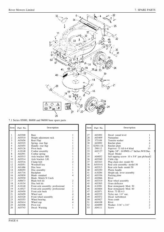
14
25
36
i
A
B
A
B
A
PAGE 11
Rover Mowers Limited
GBSelf propelled drive controlMoved towards (I) turns the clutch on and drives the mower forward.Moved towards (O) turns the clutch off and stops the mowerdriving
DSelbetantriebbetätgungEinstellung auf (I) aktiviert die Kupplung und den Motor vorwärs.Einstellung auf (I) schaltet die kupplung aus und bringt den Mäher zumStehen
FContrôle d'autotractionDéplacé vers (I) enclenche l'embrayage et fait avancer la tondeuse.Déplacé vers (O) décengage l'embrayage el empéche la tondeuse d'avancer
SPAutopropulsado marcas del controlMovido hacia (I) mueve el desembragador y pone a marcha el cortacesped.Movido hacia el (O) apaga el desembragador y para el cortacesped
NLRegulatuur bij relfverplaatsende machinesAls men de knop op (I) zet, is de koppeling ingeschakeld en de machinerijdt vooruit. Als de knop (O) zet, schakelt men de knoppeling uit en
de machine stopt.
ICamando trazione removente
Se mosso verso I (innestato) innesta la frizione e muove in avanti la
faiciatrice tosaerba. Se mosso verso O (disinnestato) disinnesta la
frizione e ferma la trazione della falciatrice tosaerba
GBOperator presense controlHandle moved towards the handle bars, engine and blades are free torotate. Handle released, engine and blades stop rotating
DBedieneranwesenheitakontrolleGiff in Richtung Giffbügel vorgestzt, motor und messer rotieren frei,Griff gelôst, Motor und messer stoppen
FContrôle par opérateurPoigée avancée vers les mancherons, moteur et lames peuvent tourner.Poignée relâchée, moteur arrêtent de tourner
SPOperador de las presencias controlesMango movido hacia manillas, motor y cuchillas estanlibres de hacervucltas. Mango disparado, motor y cuchillas paran de hacer vucltas
NLDodenmanskoop regulatuurknop die aangeeft dat de oparateuraanwezig isDe gasbedieningshendel geplaast in de richting van de hand grepen,de machine loopt en de messen draaien vrij. Gasbedieningshendel isafgezet, de machine stopt, en de messen draaicn neit meer
IComando presenza operatore(I) Manopola mossa verso barre manubrio, motere e lame in posizionelibers e rptanti. (O) manopola disimpegnata. Motre e lame fermi
GBThrottle controlMarked for off, slow and fast positions
DGasbedienungMarkierung aus, langsam sch schnell
FContrôle des gazMarque pour les positions arrêt, ralenti accéléré et
SPControl del acceleradorMarcado por apagado, despacio, rapido posiciones
NLGasknop regulatuurVoorzien van markteken uit, langzaam, snel tekening
IComandeSegno di poizione O staccato lento veloce
3632 Steel Export.PMD11/11/2002, 10:10 AM 2
Rover Mowers Limited7. SPARE PARTS
1A03802Upper handle bars-Mod 602A10016Throttle control assembly3A03581Throttle cable- Quantum4A03557Key start housing5A03560Key start switch6A07679Ignition key7A03741Wiring loom- Mod 60 CE8A03565Cable clamp9A03559Battery10A03558Battery block11A03556Battery support box12A03563Decal- caution13A02083Setscrew- 5/16" x 3/4" unc.hex.14 A02012Washer- 5/16" x 7/8" x 18g.flat15 A02223Nyloc nut- 5/16" unc.16 A02002Speed nut- 3/16" bsw.17 A02163Screw- 3/16" x 1/2" mush/head18 A04060Rivet- 73 AS 5-2
19A03610Foam block2021A10524Bale assembly- Mod 60 CE22A10503Handle assembly Mod.60- CE23A02521Spacer24A03739Handle grip- CE25A03732Cable clip- CE26A03733Rope stop- CE2728A02235Nyloc nut- 1/4" unc.29A04083Screw- 10 x 3/4 pan head3030A03722Brake cable- mod. 6031A03756Switch Plate
7.4 Powerstart spare parts - Series 85000, 86000
PAGE 9
Rover Mowers LimitedENGLISHPREFACE
WARNINGCAUTIONFollow these instructions to avoid mower damage andpossible loss of warranty
The safety of the user and others involved. Personal Injurymay result should this information be disregarded.
CONTENTSPAGE
Preface............................................................................iii
Safety Instructions..........................................................iv
1.Setting up...................................................................11.1Grass catcher assembly...................................1
2.Before operating........................................................12.1Folding handles...............................................12.2Handle bar height............................................12.3Engine lubrication...........................................12.4Fuel..................................................................12.5Controls...........................................................1
3.Operation...................................................................13.1Grass catcher...................................................13.2Adjusting the height of cut..............................13.3To start the engine...........................................13.4To stop the engine...........................................13.5Self propelled mowers.....................................13.6Blade brake control.........................................1
4.Maintenance - General..............................................24.1Engine air cleaner............................................24.2Snorkel air cleaner...........................................24.3Spark Plug.......................................................24.4Cutting assembly.............................................24.5Blade change...................................................24.6Throttle control................................................2
5.Maintenance - self propelled mowers........................25.1Drive chain lubrication....................................25.2Drive chain adjustment....................................25.3Rear drive chain inspection.............................35.4Clutch adjustment............................................35.5Clutch lining inspection..................................35.6Drive pawl lubrication.....................................35.7Drive Wheel Cleaning.....................................3
6.Maintenance powerstart mowers6.1Battery removal...............................................36.2Battery installation..........................................36.3Battery charging..............................................36.4Care and handling............................................3
7.Spare parts.................................................................67.1Series 85000, 86000, 96000 base....................67.2Series 85000, 86000, 96000 bars....................77.3Self-propelled..................................................87.4Powerstart........................................................9
ILLUSTRATIONS.................................................PAGE
Figure 1.Grass catcher assembly...............................iFigure 2.Handle bar height adjustment.....................iFigure 3.Throttle control markings...........................iFigure 4.Operator presence control...........................iFigure 5.Self propelled drive control........................iFigure 6.Grass catcher fitment..................................iFigure 7.Height adjustment......................................iiFigure 8.Blade bolt assembly...................................iiFigure 9.Drive chain cover plate..............................iiFigure 10.Drive chain.................................................iiFigure 11.Drive shaft cover........................................iiFigure 12.Stone cover................................................iiFigure 13.Clutch adjustment......................................iiFigure 14.Drive wheel................................................iiFigure 15.Drive pinion...............................................iiFigure 16.Powerstart control......................................ii
iii
Thank you for buying a Rover Product. All Rover Lawn mowers are designed and constructed to give optimum grass cuttingperformance under normal grass cutting conditions.
This manual covers the operation and maintenance of the Rover walk behind mower. Please read and understand this ownersmanual, before using the mower.If any point is unclear, contact Rover Mowers Limited or any authorised Rover Mower service dealer.
Rover Mowers Limited reserves the right to make changes of, and add improvements upon, its product at anytime, without noticeor obligation. The Company also reserves the right to discontinue manufacture of any product at its discretion at any time.
To emphasise special information, the words WARNING and CAUTION are used.
Rover Mowers Limited 7. SPARE PARTS
1 A03300 Base 12 A03510 Height adjustment rack 13 A03456 Rear Flap 14 A03325 Spring- rear flap 15 A03455 Handle- rear flap 16 A03126 Pivot bush 27 A10148 Conbar assembly 18 A02591 Conbar spring 19 A03515 Axle bracket- RH. 110 A03514 Axle bracket- LH. 111 A03516 Clamp bolt 212 A02051 Woodruff key 113 A01486 Disc boss 114 A00293 Disc assembly 115 A01716 Backplate 116 A03830 Blade- standard 416 A03930 Blade- Mulch N Catch17 A00673 Blade bolt kit 218 A10154 Disc bolt kit 119 A10140 Front axle assembly- professional 119 A10527 Front axle assembly- professional 120 A03450 Front axle bush 221 A03459 Wheel seal 422 A03320 Front wheel assembly 223 A03353 Wheel bearing 824 A03414 Wheel cap 425 A03306 Pivot rod 126 A03743 Decal- Warning 1
27 A03492 Decal- sound level 128 A03409 Nameplate 129 373109 Tension washer 430 A03092 Ratchet plate 431 S2501116 Ratchet plate 232 290112 Poprivet- 73 AS 6-4 blind 1033 A02127 Taptite- 3/8" - 16 HWH x 1" Ind.hex.W/H Duo. 334 * Decal- Model 135 A04052 Self tapping screw- 10 x 5/8" pan ph/head236 A03549 Cable clip 137 A03323 Plug chain slot- model 50 138 A010141 Rear axle assembly- model 50 139 A03313 Rear axle bush- model 50 240 A03250 Plastic handle 141 A10284 Height adj. lever assembly 142 A03336 Packing plate 143 A02066 Rivet 244 A03319 Rear wheel assembly 245 A03303 Grass deflector 146 A10381 Rear stoneguard- Mod. 50 146 A03604 Rear stoneguard- Mod. 60 147 A02071 Rivet- 73 SS 4-3 248 A02235 Nyloc nut- 1/4" unc. 249 A03472 Decal- turbothrust 150 A03927 Nose comb 151 A04108 Rivet 252 A04099 Washer- 3/16" x 3/4" 253 A04111 Screw 2
7.1 Series 85000, 86000 and 96000 base spare parts
PAGE 6
26
Rover Mowers Limited ENGLISH 4. MAINTENANCE GENERAL
5. MAINTENANCE - Self propelled mowers
5.1 Drive chain lubrication
1. Remove the spark plug lead.2. Remove the cover plate screws (a) and lift off the cover plate (b).
Figure 9.3. Support the rear wheels off the ground to enable the drive to be
rotated.4. Use SAE 30 oil and lubricate the drive chains at point (a) whilst
the chain is being rotated. Figure 10.5. Replace the chain cover plate and secure.6. Replace the spark plug lead.
5.2 Drive chain adjustment
Front drive chain1. Remove the spark plug lead.2. Remove the cover plate.3. Loosen the chain tensioner bolt (b) and move the chain tensioner to
give a 3 mm deflection on the drive chain. Figure 10.4. Tighten the chain tensioner bolt and rotate the drive wheels to check
the drive chain for tight spots.5. Replace the cover plate.
Rear drive chain1. Remove the spark plug lead.2. Loosen the rear drive chain tension nut (c) and slide it upwards to
tighten the rear drive chain. Figure 9.3. Retighten the rear drive chain tensioner nut and rotate the rear drive
wheels to check for tight spots.4. Replace the spark plug lead.
5.3 Rear drive chain inspection
1. Remove the spark plug lead.2. Remove the drive shaft cover plate retaining screws (a) and remove
cover plate (b). Figure 11.3. Remove the stone guard retaining screws (c) and remove the stone
guard. Figure 11.4. Remove the chain guard nuts (d) and slide the chain guard out of the
way. Figure 12.5. Inspect the drive chain and axle sprocket and replace if found to have
excessive wear.6. Replace the stone guard and drive shaft axle plate.7. Replace the spark plug lead.
5.4 Clutch adjustment
1. Remove the spark plug lead.2. Loosen the locknut (a) and turn the adjuster (b) clockwise until the
clutch is felt to drag. Figure 13.3. Back off the adjuster anti-clockwise 2-3 turns and retighten locknut
(a).4. Replace the spark plug lead.
4.1 Engine air cleaner
Refer to the engine manufacture's instructions for detailed cleaninginstructions.The engine air cleaner element must be serviced after each 25 hours ofnormal mowing. The element must be serviced more regularly if themower is used in dusty conditions.
4.2 Snorkel air intake
The snorkel air cleaner element must be serviced after each 50 hours ofnormal mowing. The element must be serviced more regularly if themower is used in dusty conditions.
1. Disconnect the air tube from the element holder.2. Remove the holder cap.3. Remove the cartridge and tap gently on a flat surface to remove dirt.4. Replace element in holder and replace holder cap.5. Replace the air tube to the bottom of the element holder.
NOTE: Quantum engines fitted with a Remote snorkel airintake are not fitted with an air cleaner element. Note theair cleaner element on this model is located on the engine.
CAUTION
Do not allow dirt to enter the air tube, engine damage may occur.Check the condition of the air tube regularly and replace ifdamaged.
4.3 Spark plug
For best results remove and check the condition of the spark plug every25 hours of use.
1. Stop the engine and remove the spark plug lead.2. Clean dirt from around the spark plug and remove the spark plug.3. If a new spark plug is required use a Champion RJ19LM or
equivalent and set the electrode gap at 0.7 to 0.8 mm.4. Screw the spark plug into the engine and tighten to 20NM.
4.4 Cutting assembly
1. Disconnect the spark plug lead.2. Move the height of cut lever to the high cut position, and fold the
handle bars.3. Tilt the mower so that the spark plug is up.4. Inspect the cutting assembly for damage and wear.5. Check the disc retaining bolts. Tighten the centre bolt to 48 Nm.and
the three concentric bolts to 14 Nm.6. Return mower to its normal position and replace the spark plug lead.
WARNING
Remove the spark plug lead before working on cutting assembly.Do not work on the cutting assembly without wearing gloves.
4.5 Blade change
1. Disconnect the spark plug lead.2. Set the mower to the high cut position.3. Lift the rear flap on rear catcher mowers and prop open the flap to
give access to the blades.Tilt utility mowers so that the spark plug is up.
4. Remove the blade, blade retaining bolts, nuts and washers anddiscard. Retain only the ‘D’ plates.
5. Fit new blades, blade bolts, washers, and nuts in sets to maintainbalance. Figure 8.
6. Tighten the blade nuts to 16 NM. Check the blades are free to movewhen the blade nut is tensioned.
7. Remove the flap prop or lower the mower to the ground and replacethe spark plug lead.
4.6 Throttle control
Each 25 hours of mowing use a small amount of light oil to lubricatethe throttle control lever.
Page 2
CAUTION
Do not over tighten the spark plug as engine damage may occur.
Rover Mowers Limited 7. SPARE PARTS
PAGE 8
1 A02102 Washer- Avdel 7601/00102 A10177 Clutch lever3 A03365 Clutch cable4 A07822 Cable tie5 A03314 Rear axle support6 A03391 Stoneguard mount bracket7 A03383 Rear stoneguard- 960127 A10381 Rear stoneguard- 86012, 860408 A03393 Drive shaft cover9 A02090 Circlip- 1400/1210 A03373 Pawl retainer washer11 A03371 Drive pinion- RH12 A03372 Pawl13 A03361 Bearing- 6001 DDU14 A07675 Nylon bush15 A10172 Rear axle assembly16 A03366 Rear chain guard17 A03394 Felt seal18 A02069 Roll pin- 1/8" x 3/4"19 A03368 Rear drive shaft sprocket20 A03382 Dust seal21 A03353 Wheel bearing22 A03352 Geared wheel hub23 A03441 Washer plate
24 A03414 Wheel cap25 A03369 Drive shaft26 A03377 Rear drive chain27 A03364 Cable support bracket- RH28 A03367 Chain tensioner29 A03360 Clutch engagement bush30 A10171 Driver clutch plate31 A03358 Clutch spring32 A10170 Driven clutch plate33 A03359 Clutch support shaft34 A03550 Drive chain housing- LH35 A03363 Cable support bracket- LH36 A03370 Drive pinion- LH37 A04052 Self tapping screw- 10 x 5/8" pan ph/head38 A03552 Chain guard cover plate39 A03551 Drive chain housing- RH40 A03386 Felt seal41 A02070 Roll pin- 3/16" x 7/8"42 A03354 Sprocket PTO.43 A03376 Front drive chain44 A03375 Pivot rod45 A03250 Handle46 A02146 Setscrew- 1/4" x 3/4" unc.hex47 A02214 Setscrew- 1/4" x 5/8" unc.hex
48 A02078 Setscrew- 1/4" x 1/2" unc.hex49 A02081 Setscrew- 1/4" x 1-3/4" unc.hex50 A02235 Nyloc nut- 1/4" unc.51 S2491162 Nut- 1/4" unc.square pressed52 A02001 Nut- 1/4" unc.hex53 A03092 Washer- Avdel 7301/001654 A02030 Washer- 5/16" x 5/8" x 18g.flat55 A02209 Washer- 1/4" x 5/8" x 18g.flat56 A02044 Washer- 1/4" internal shakeproof57 S373109 Tension washer58 A10146 Wheel assembly59 S2501108 Washer- Avdel 7301/000860 A10284 Height adjustment lever assembly61 A02118 Rivet- 3/4" x 1/4" flat head62 A03336 Plate63 S3521047 Wheel plug64 A03470 Chain guide65 290112 Rivet- 73 AS 6-4 blind66 A03390 Clutch plate lining67 A03384 Tyre68 A10524 Bale assembly CE69 A10503 Handle assembly CE70 A03739 Handle grip CE71 A02521 Spacer CE72 A03604 Rear extension- Mod. 60
7.3 Self propelled spare parts
Rover Mowers Limited ENGLISH SAFETY INSTRUCTIONS
Safety Instructions1. Training
a. Read the instructions carefully. Be familiar with thecontrols and the proper use of the equipment.
b. Never allow children or people unfamiliar with theseinstructions to use the mower. Local regulations mayrestrict the age of the operator.
c. Never mow while people, especially children, or petsare nearby.
d. Keep in mind that the operator or user is responsiblefor accidents or hazards occurring to other people ortheir property.
2. Preparation
a. While mowing, always wear substantial footwear andlong trousers.Do not operate the equipment when barefoot orwearing open sandals.
b. Thoroughly inspect the area where the equipment isto be used and remove all stones, sticks, wires,bones and other foreign objects.
c. WARNING- Petrol is highly flammable.
Take the following precautions.i. Store fuel in containers specially designed for this
purpose.ii. Refuel outdoors only and do not smoke whilerefuelling.iii. Add fuel before starting the engine. Never remove
the cap of the fuel tank or add petrol while the engineis running or when the engine is hot.iv. If petrol is spilled, do not attempt to start theengine but move the machine away from the area ofspillage and avoid creating any source of ignitionuntil petrol vapours have dissipated.v. For reasons of safety the petrol tank and tank cap lock must be
replaced if damaged.d. Replace faulty silencers.e. Before using, always visually inspect to see that the
blades, blade bolts and cutter assembly are not worn ordamaged. Replace worn or damaged blades in sets topreserve balance.
f. On multibladed machines, take care as rotating oneblade can cause other blades to rotate.
3. Operation
a. Do not operate the engine in a confined space wheredangerous carbon monoxide fumes can collect.
b. Mow only in daylight or in good artificial light.c. Avoid operating the equipment in wet grass, where
feasible.d. Always be sure of your footing on slopes.e. Walk, never run.f. For wheeled rotary machines, mow across the face of
slopes, never up and down.g. Exercise extreme caution when changing direction on
slopes.
h. Do not mow excessively steep slopes.i. Use extreme caution when reversing or pulling the
mower towards you.j. Stop the blade(s) ,if the mower has to be tilted for
transportation when crossing surfaces other than grassand when transporting the mower to and from the areato be mowed.
k. Never operate the mower with defective guards orshields, or without safety devices, for example deflectorsand/or grass catchers in place.
l. Do not change the engine governor settings or overspeedthe engine.
m. Disengage all blade and drive clutches before startingthe engine.
n. Start the engine or switch on the mower carefullyaccording to instructions and with feet well awayfrom the blade(s).
o. Do not tilt when starting the engine or switching onthe motor, unless the mower has to be tilted forstarting. In this case, do not tilt it more than absolutelynecessary and lift only the part which is away from theoperator.
p. Do not start the engine when standing in front of thedischarge chute.
q. Do not put hands or feet near or under rotating parts.Keep clear of the discharge opening at all times.
r. Never pick up or carry a mower while the engine isrunning.
s. Stop the engine and disconnect the spark plug lead:i. Before clearing blockages or unclogging the chute.ii. Before checking, cleaning or working on the mower.iii. After striking a foreign object. Inspect the mower for
damage and make repairs before restarting andoperating the mower.
iv. If the mower starts to vibrate abnormally checkimmediately.
t. Stop the enginei. Whenever you leave the mower.ii. Before refuelling.
u. Reduce the throttle setting during engine run-out and ifthe engine is provided with a shut-off valve, turn off thefuel at the conclusion of mowing.
4. Maintenance and storage.
a. Keep all nuts, bolts, and screws tight to be sure theequipment is in safe working condition.
b. Never store the equipment with petrol in the tank insidea building where fumes may reach an open flame orspark.
c. Allow the engine to cool before storing in any enclosure.d. To reduce the fire hazard, keep the engine, silencer,
battery compartment and petrol storage area free ofgrass, leaves, or excessive grease.
e. Check the grass catcher frequently for wear ordeterioration.
f. Replace worn or damaged parts for safety.g. If the fuel tank has to be drained, do this outdoors.
iv
3632 Imposed PDF's.indd 3 18/05/2006 2:36:10 PM
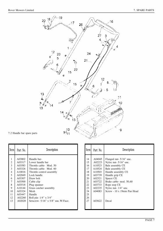
Rover Mowers Limited ENGLISH 1. SETTING UP
3. Press firmly down on the catcher top to lock the barbs into slots.Figure 1.
4. Secure with two screws provided.
2. BEFORE OPERATING
2.1 Folding handles
l. Locking knobs- By turning these knobs the handle bars can be eitherlocked in the operating position or folded for storage.
2. Locking lever- Lift the lever to release the handle bars for foldingor push the lever closed to lock handle bars in the operating position.Adjust the tension by turning the lock nut with a 1/2" AFspanner.
2.2 Handle bar height
1. Loosen the two nuts (A) at the base of the handle bars on both sidesof the mower using a 1/2" AF spanner. Figure 2.
2. Move the handle bars to the required position and tighten the handlebars nuts.
2.3 Engine lubrication
The engine oil level must be checked before attempting to start the engine.Refer to the engine manufacturer's instructions.1. Position the mower on a level surface and clean around the dip stick
or oil plug.2. Remove the dip stick or oil plug.3. Using a clean funnel slowly add oil in accordance with the engine
manufacturer's instructions.4. Check the oil level by screwing in the dip stick or oil plug and
removing again. When oil level is correct replace the dip stick.
CAUTION
Avoid premature engine failure by using a clean funneland clean away any possible contaminants.
2.4 Fuel
1. Position the mower on a level surface in a well ventilated area andclean around the fuel tank cap.
2. Using a clean funnel fill the fuel tank with unleaded petrol.3. Replace the fuel tank cap and clean away any spilt petrol.
2.5 Controls
Throttle ControlMarked for O (off) (slow) (fast) positions. Figure 3.Operator Presense ControlHandle moved towards the handle bars (I). Engine and blades are free torotate. Handle released (0) engine and blades stop rotating. Figure 4.Self Propelled Drive ControlMoved towards 1 (on) turns the clutch on and drives the mower forward.Moved towards O (off) turns the clutch off and stops the mower driving.Figure 5.PowerstartTurn the key to on (I) position to engage the electric starter. release the keywhen the engine starts and allow to return to the off (0) position. Figure16.
3.1 Grass catcher
Installing the grass catcher
1. Raise the rear flap of the mower.2. Grasp the grass catcher by the top handle and position the grass
catcher against the rear of the mower. Figure 6.3. Lower the rear flap so that the back edge of the flap hooks over the
grass catcher.
Removing the grass catcher
1. Grasp the grass catcher top handle and lift up.2. Raise the rear flap of the mower to release grass catcher.3. Lift the grass catcher clear of the mower and lower the rear flap.
3.2 Adjusting the height of cut
1. Grasp the height of cut lever (A) and apply an outward pressure torelease the lever from the rack (B). Figure 7.
2. Move the lever while holding out to the required height of cutposition and engage the lever in the rack by releasing the lever.
3.3 To start the engine
1. Move the Throttle Control lever to the fast position.2. Press the primer bulb firmly 5 times.3. Grasp the 'Operator presence control handle' and hold against the
handle bars. Refer engine manufacturers instructions. Fig. 4.4. Grasp the starter handle and pull, or turn the ignition key on
Powerstart mowers.5. After engine starts, move the Throttle Control to the slow position.
CAUTION
With powerstart mowers if the engine fails to start after 3seconds of continuous cranking release the ignition key andwait 10 seconds before trying to restart the engine. If the enginestill fails to start check the fuel level, battery connections, andbattery condition. If the engine is cranking slowly the batterymay need charging, refer to section 6.3 for battery charging.
3.4 To stop the engine
1. Move the throttle control lever to the stop position. O2. Release the “Operator presence control handle”.3. Turn the fuel tap off where fitted.4. Remove the ignition key on Powerstart mowers.
3.5 Drive engagement - Self propelled mowers
1. Start the engine and set the engine speed to the required grass cuttingspeed.
2. Push forward on the clutch engagement lever to engage the self-propelled drive to the rear wheels. Fig. 5.
3. To disengage the self-propelled drive release the engagementlever and allow it to return to the disengaged position.
CAUTION
Do not hold the engagement lever in a semi-engaged position toslip the clutch as this will lead to excessive clutch wear.
3.6 Blade Brake ControlThe mower engine is fitted with a blade brake system. When the“Operator Presence Control” is held against the handle bars the brake isoff (0). When the Operator presence control is released the blade brake ison (I).
1.1 Grass catcher assembly
1. Locate the catcher handle and align its front lugs with the slotsin the top of the catcher and press firmly into position. Figure 1.
2. Position the catcher top over the catcher bottom, aligning the barbson the top with the slots in the bottom. Figure 1.
3. OPERATION
Page 1
Rover Mowers Limited 7. SPARE PARTS
7.2 Handle bar spare parts
1 A03802 Handle bar-2 A03317 Lower handle bar3 A03583 Throttle cable- Mod. 503 A03326 Throttle cable- Mod. 604 A10016 Throttle control assembly5 A02849 Lock handle6 A03307 Draw bolt7 A03500 Cable clip8 A03518 Plug spanner9 A10144 Grass catcher assembly10 A03324 Mesh11 A03447 Handle12 A02260 Roll pin- 1/4" x 3/4"13 A02028 Setscrew- 5/16" x 5/8" unc.W/Face.
14 A04045 Flanged nut- 5/16" unc.15 A02223 Nyloc nut- 5/16" unc.16 A10523 Bale assembly CE17 A10524 Bale assembly CE18 A10503 Handle assembly CE19 A03739 Handle grip CE20 A02521 Spacer CE21 A03722 Brake cable- mod. 50,6022 A03733 Rope stop CE23 A02235 Nyloc nut- 1/4" unc.24 A04083 Screw - 10 x 19mm Pan Head252627 A03622 Decal
PAGE 7
Page 3
6.1 Battery removal
1. Remove the two retaining screws from each side of the batterysupport box and remove the front cover.
2. Remove the battery from the support box and simultaneouslydisconnect the wiring loom from the battery terminals.
6.2 Battery installation
1. Connect the mower wiring loom to the battery with the red leadattached to the positive (+) terminal of the battery and the black leadto the negative (-) terminal of the battery.
2. Fit the two rubber blocks to each end of the battery and place thebattery complete with the rubber blocks into the battery support boxwith the battery terminals closest to the centre of the mower.
3. Refit the battery support box front cover and retain with the twoscrews.
6.3 Battery charging
A new battery when supplied with the mower may not be fullycharged to maximum capacity. The battery should have an initialcharging period of 10 to 16 hours. To charge the battery it must beremoved from the mower first.
CAUTION
Use only an approved battery charger supplied by the mowerdealer which has been designed for use with this battery.
1. Connect the battery charger to the battery with thered lead (positive) to the positive (+) terminal of thebattery and the black (negative) lead to the negative(-) terminal of the battery.
2. Connect the battery charger to a suitable mainspower outlet and switch on.
3. When charging is complete after 10 to 16 hours, switch off the poweroutlet and disconnect the battery charger from the power outlet.
4. Disconnect the battery charger leads from the battery and refit thebattery to the mower.
6.4 Care and handling
1. Do not disassemble the battery, as it’s strong acid electrolyte mayburn your skin or clothes.
2. Do not short out the battery terminals, as this may burn the terminalsand cause damage to the equipment.
3. Do not incinerate the battery to depose of them.The battery may explode if exposed to fire.
4. Clean the battery with a dry cloth only, never use oil, petrol, thinnersor any other petrochemical.
5. Handle the battery with care. If the battery is dropped and the caseis damaged the acid electrolyte (sulphuric acid) may leak out. Wipeup leaking acid with a cloth and neutralise acid with an alkalinesolution.
6. In the event of electrolyte coming into contact with the skin,immediately flush with water and seek medical attention.
5.5 Clutch lining inspection
1. Remove the spark plug lead.2. Remove the cover plate as explained in section 5.1 “Drive chain
lubrication”.3. Check the thickness of the friction material. Figure 13. If thickness
of the friction material is less than 1mm the clutch plate should bereplaced by an authorised Rover Mowers Limited Dealer.
5.6 Drive pawl lubrication
1. Remove the spark plug lead.2. Support the rear wheels off the ground.3. Remove the rear drive wheel cap (a) and the wheel plug (b). Figure
14.4. Rotate the drive wheel to align the drive pinion with the wheel plug
hole.
5. Lubricate the slot at the centre of the drive pinion (d). Figure 15.6. Replace the wheel plug and wheel cap.7. Replace the spark plug lead.
5.7 Drive wheel cleaning
1. Remove the spark plug lead.2. Support the rear wheels off the ground and remove the wheel cap.3. Remove the ratchet plate (c) retaining the wheel to the axle.
Figure 15.4. Remove the wheel from the axle and clean the inside of the wheel
hub.5. Replace the wheel and retain using a new ratchet plate.6. Replace the wheel plug and wheel cap.7. Replace the spark plug lead.
6. MAINTENANCE - Powerstart Mowers
Rover Mowers Limited ENGLISH 5. MAINTENANCE - Self propelled mowers Rover Mowers Limited ITALIANO 5. MANUTENDIONE
Pagina 3
5.5 Ispezione rivestimento frizione
1. Staccare il cavetto dalla candela.
2. Rimuovere la piastra di ricoprimento come spiegato in
sezione 5.1 “Lubrificazione catena trasmissione”.
3. Controllare lo spessore del rivestimento della frizione.
Figura 13. Se tale spessore e’ inferiore a 1 mm il piatto
frizione dovrebbe essere sostituito, consigliabilmente presso
il rivenditore autorizzato della Rover Mowers Limited.
5.6 Lubrificazione ingranaggio trasmissione
1. Staccare il cavetto dalla candela.
2. Rialzare da terra con un sostegno le ruote posteriori.
3. Levare il copri perno (a) e il perno (b) della ruota motrice.
Figura 14.
4. Girare la ruota motrice in modo da allineare il pignone di
trasmissione con il foro del perno della ruota.
5. Lubrificare la fessura al centro del pignone di trasmissione
(d). Figura 14.
6. Rimettere a posto il perno ed il copriperno della ruota.
7. Riattaccare il cavetto della candela.
5.7 Pulizia ruota motrice
1. Staccare il cavetto della candela.
2. Rialzare da terra le ruote posteriori e levare il copri perno
della ruota.
3. Togliere la piastrina d’arresto (c) che ferma la ruota all’asse.
Figura 15.
4. Levare la ruota dall’asse e pulirne il mozzo.
5. Nel rimettere la ruota a posto usare una piastrina d’arresto
nuova.
6. Rimettere a posto il perno e il copriruota.
7. Riattaccare il cavetto alla candela.
6.1 Rimozione batteria
1. Svitare le due viti di ritegno ai due lati della scatola
portabatteria e levarne il lato anteriore.
2. Togliere la batteria dalla scatola e nel medesimo tempo
staccare i fili dai morsetti della batteria.
6.2 Installazione batteria
1. Collegare i cavi elettrici della falciatrice alla batteria, con il
cavo rosso collegato al morsetto positivo (+) della batteria
e il cavo nero al morsetto negativo (-) della batteria.
2. Mettere i 2 pezzi di gomma ai lati estremi della batteria e
sistemare la batteria con i pezzi di gomma nella scatola
portabatteria con i morsetti in posizione piu’ vicina al centro
della falciatrice.
3. Rimettere a posto il lato anteriore della scatola portabatteria
e fissarlo con le due viti.
6.3 Caricamento batteria
Una batteria nuova, fornita insieme alla falciatrice potrebbe
alle volte non essere carica alla sua capacita’ massima.
Normalmente la batteria dovrebbe avere un periodo di carica
da 10 a 16 ore. Per caricare la batteria bisogna prima levarla
dalla falciatrice.
AVVERTENZA
Usare solo un caricabatteria approvato dalla
fabbrica e fornito dal distributore della falciatrice
perche’ si tratta di un prodotto appositamente
studiato per questo tipo di batteria.
1. Collegare il caricabatteria con la batteria: il cavo rosso
(positivo) collegato al morsetto positivo (+) della batteria ed
il cavo nero negativo al morsetto negativo (-) della batteria.
2. Collegare il caricabatteria con una presa elettrica adatta e
accendere l’interruttore.
3. Quando, dopo circa 10-16 ore si e’ completata la carica,
spegnere l’interruttore della presa elettrica e staccare la
spina del caricabatteria dalla presa elettrica.
4. Staccare i cavi del caricabatteria dalla batteria e risistemare
la batteria nel portabatteria della falciatrice.
6.4 Cura e uso
1. Non smontare la batteria in quanto l’acido dell’elettrolite
potrebbe bruciare la pelle o gli indumenti.
2. Non mettere in corto circuito i morsetti della batteria, in
quanto cio’ potrebbe bruciare i morsetti stessi e causare
danni all’equipaggiamento elettrico.
3. Non mettere la batteria nell’incineratore, nell’intento di
disfarsene. La batteria puo’ esplodere se esposta al fuoco.
4. Pulire la batteria solo con panni asciutti, non usar mai olio,
benzina, solventi o qualsiasi altro prodotto petrolchimico.
5. Maneggiare con cura la batteria. Se si fa cadere la batteria
e il contenitore si e’ danneggiato puo’ uscirne fuori dell’acido
dell’elettrolite (acido solforico). Pulire bene l’acido con un
panno e neutralizzare l’acido con una soluzione alcalina.
6. Nel caso in cui tale elettrolite venga in contatto con la pelle,
lavare subito con acqua e richiedere assistenza medica.
6. MANUTENDIONE FALCIATRICI ADIGNIZIONEELECTRICA
3632 Steel Export.PMD 11/19/2002, 2:46 PM8
Rover Mowers LimitedITALIANO 4. MANUTENZIONE GENERALE
Pagina 2
4.1Filtro aria motore
Per istruzioni dettagliate sulla pulizia del filtro si prega riferirsi almanuale rilasciato dalla fabbrica del motore.L’elemento del filtro aria del motore deve essere pulito dopo ogni 25 oredi falciatura normale. Se pero’ si e’ falciato in condizioni polverosel’elemento dovra’ essere pulito piu’ frequentemente.
4.2Filtro aria tubo aspirazione
L’elemento del filtro aria dell’aspiratore deve essere pulito dopo ogni50 ore di falciatura normale. Se pero’ si e’ falciato in condizionipolverose l’elemento dovra’ essere pulito piu’ frequentemente.
1.Staccare il tubo aspiratore dal portaelemento.2.Staccare il coperchietto del portaelemento.3.Rimuovere l’elemento filtro e batterlo gentilmente su una superfice
piatta per rimuoverne la polvere.4.Rimettere a posto l’elemento e rimettere il coperchietto sul porta
elemento.5.Rimettere a posto il tubo aspiratore alla base del portaelemento.
Pregasi notare che i motori "Quantum" con tubo di respirazioned'aria lontano, non sono dotati di filtro dell'aria. Notare ancheche il filtro dell'aria in questo modello è messo sopra il motore.
AVVERTENZA
Non far entrare polvere nel tubo aspiratore aria per nonprovocare danni al motore. Controllare regolarmente lecondizioni del tubo aspiratore aria e sostituirlo sedanneggiato.
4.3Candela
Per ottenerne i migliori risultati levare la candela e controllarne lecondizioni ogni 25 ore d’uso.
1.Fermare il motore e staccare il cavetto dalla candela.2.Pulire intorno alla candela e levare la candela.3.Se occorre una nuova candela usare una Champion RJ19LM o
equivalente e regolare la distanza dell’elettrodo tra 0.7 e 0.8 mm.4.Riavvitare la candela nel motore e stringere fino a 20 NM.
AVVERTENZA
Non stringere troppo la candela per non causare danni almotore.
4.4Apparato taglio
1.Staccare il cavetto dalla candela2.Spostare la leva d’altezza taglio nella posizione piu’ alta.3.Muovere la falciatrice in modo da avere la candela nella parte
superiore.4.Ispezionare l’apparato taglio e vedere se ci sono danni o logorii.5.Controllare i bulloni che fissano il disco. Stringere il bullone al
centro fino a 48 NM e i 3 bulloni concentrici fino a 14 NM.6.Riportare la falciatrice in posizione normale e riattaccare il cavetto
alla candela.
AVVERTENZA
Staccare il cavetto dalla candela prima di lavoraresull’apparato taglio.
4.5Cambio lame
1.Staccare il cavetto dalla candela.2.Mettere la falciatrice in posizione di taglio alto.3.Alzare lo sportello posteriore nelle falciatrici a raccoglitore posteriore
e tenerlo aperto con l’apposito sostegno cosi’ da avere liberoaccesso alle lame. Alzare le falciatrici utilitarie in modo da averela candela in alto.
4.Togliere le lame, i bulloni di ritegno, i dadi e le rondelle e scartareil tutto. Lasciare solo le piastre ‘D’.
5.Mettere le lame nuove, i bulloni, le rondelle e i dadi in gruppicompleti per mantenere l’equilibrio. Figura 8.
6.Stringere i dadi delle lame fino a 16 NM. Controllare che le lamesi possano muovere liberamente quando i loro dadi sono intensione.
7.Rimuovere il sostegno dello sportello, riabbassare l’altezza taglioe riattaccare il cavetto alla candela.
4.6Controllo accelleratore
Ogni 25 ore di falciatura lubrificare la leva di controllo accelleratore conun po’ d’olio leggero.
5. MANUTENZIONE FALCIATRICI SEMOVENTI
5.1Lubrificazione catena trasmissione
1.Staccare il cavetto dalla candela.2.Levare le viti (a) della piastra di ricoprimento e sollevarla (b).
Figura 9.3.Alzare e tenere alzate con un sostegno le ruote posteriori in modo
che si possa girare liberamente la trasmissione.4.Lubrificare con olio SAE 30 la catena di trasmissione al punto (a)
mentre si fa ruotare la catena stessa. Figura 10.5.Rimettere a posto la piastra e fissarla con le viti.6.Riattaccare il cavetto alla candela.
5.2Regolazione catena trasmissione.
Catena tramissione anteriore1.Staccare il cavetto dalla candela.2.Rimuovere la piastra di ricoprimento.3.Allentare il bullone del tirante (b) della catena e muovere il tirante
fino a dargli 3 mm di deviazione rispetto alla catena di trasmissione.Figura 10.
4.Stringere il bullone del tirante e far girare le ruote motrici percontrollare se nella catena di trasmissione ci sono punti troppo tesi.
5.Rimettere a posto la piastra di ricoprimento.Catena trasmissione posteriore1.Staccare il cavetto dalla candela.2.Allentare the il dado (c) del tirante della catena di trasmissione
posteriore e farlo scorrere verso l’alto in modo da tendere la catenadi trasmissione posteriore. Figura 9.
3.Stringere il dado del tirante della catena di trasmissione posteriore
e ruotare le ruote motrici per controllare se ci sono dei punti troppotesi.
4.Riattaccare il cavetto alla candela.
5.3Ispezione catena trasmissione posteriore
1.Staccare il cavetto dalla candela.2.Svitare le viti che fissano la piastra di ricoprimento dell’albero di
trasmissione (a) e levare la piastra stessa (b). Figura 11.3.Svitare le viti di ritegno del parasassi (c) e levare il parasassi stesso.
Figura 11.4.Svitare i dadi (d) del paracatena e far scivolar via il paracatena
stesso. Figura 12.5.Ispezionare la catena di trasmissione e l’ingranaggio dell’asse e, se
trovato eccessivamente consumato, sostituirlo.6.Rimettere a posto il parasassi, il paracatena e la piastra dell’albero
di trasmissione.7.Riattaccare il cavetto alla candela.
5.4Regolazione frizione
1.Staccare il cavetto dalla candela.2.Allentare il dado di fissaggio (a) e girare il registro (b) in senso
orario fino a che la frizione faccia attrito. Figura 13.3.Rigirare indietro in senso antiorario il registro per 2 o 3 giri e
stringere il dado di fissaggio.4.Riattaccare il cavetto alla candela.
Rover Mowers LimitedDEUTSCH VORWORT
Verehrter Kunde,Wir bedanken uns, daß Sie ein Rover Produkt gekauft haben. Alle Rover-Rasenmäher sind entworfen und konstruiert, optimalesGrasschneiden unter normalen Grasschneideverhältnissen zu gewährleisten.
Diese Gebrauchsanweisung erklärt die Inbetriebnahme und Wartung des Rover Mähers. Beachten Sie bitte vor Inbetriebnahme die Hinweisein der Gebrauchsanweisung.
Sollte etwas unklar sein, verständigen Sie bitte Rover Mowers Limited oder einen ortszuständigen Beauftragten des Rover Kundendienstes.
Rover Mowers Limited behält sich das Recht vor, Änderungen und Verbesserungen zu jeder Zeit, ohne Ankündigung und unverbindlich,an ihrem Produkt vorzunehmen. Die Firma behält auch das Recht vor, die Herstellung irgendwelchen Produktes nach eigenem Ermessenzu jeder Zeit einzustellen.
Um besondere Information zu betonen, werden die Wörter VORSICHT und ACHTUNG benützt.
VORSICHT
Sorgen Sie für die Sicherheit des Bedieners und Dritten imArbeitsbereich des Gerätes. Sicherheitsmaßnahmen müssenbeachtet werden, um Unfälle zu verhindern.
INHALT........................................................................SEITE
Vorwort................................................................................iii
Sicherheitshinweise.................................................................iv
1.Montage.............................................................................11.1Grasfangvorrichtung................................................1
2.Vor Inbetriebnahme...........................................................12.1Klappgriffbügel.......................................................12.2Griffhöhe.................................................................12.3Ölen des Motors.......................................................12.4Benzin......................................................................12.5Bedienung................................................................1
3.Inbetriebnahme..................................................................13.1Grasfangvorrichtung................................................13.2Schnitthöhe einstellen..............................................13.3Anlassen des Motors................................................13.4Abstellen des Motors...............................................13.5Selbstangetriebene Mäher........................................13.6Messerbremeuug......................................................1
4.Allgemeine Wartung.........................................................24.1Motorluftreiniger.....................................................24.2Schnorchelluftfiten..................................................24.3Zündkerze................................................................24.4Schneidwerkzeug.....................................................24.5Messerwechsel.........................................................24.6Gashebelkontrolle....................................................2
5.Wartung für selbstangetriebene Mäher ............................25.1Ölen der Antriebskette.............................................25.2Einstellung der Antriebskette.................................25.3Kontrolle der hinteren Antriebskette.......................25.4Einstellung der Kupplung........................................25.5Kontrolle des Kupplungsbelages.............................35.6Ölen der Antriebssperrklinke...................................35.7Reinigung des Antriebsrades...................................4
ACHTUNG
Folgen Sie diesen Hinweisen, um Schaden am Mäher undeventuelle Ungültigkeit der Garantie zu vermeiden.
6.Wartung für Powerstart Mäher6.1Entfernung der Batterie...........................................36.2Einbau der Batterie..................................................36.3Batterieaufladung.....................................................36.4Pflege und Umgang.................................................3
7.Technische Daten............................................................. 47.1Bescheinigung der Übereinstimmung..................4,5
8.Ersatzteile..........................................................................68.1Serie 85000, 86000, 96000 Mäher...........................68.2Serie 85000, 86000, 96000 Griffbügel....................78.3Selbstangetriebener Mäher......................................88.4Powerstart Mäher.....................................................9
ABBILDUNGEN............................................................SEITE
Abb. 1.Grasfangvorrichtung...............................................iAbb. 2.Griffhöhe Einstellung.............................................iAbb. 3.Gasmarkierung.......................................................iAbb. 4.Bedieneranwesenheitakontrolle.............................iAbb. 5.Selbstantriebmarkierung........................................iAbb. 6.Einhängen der Fangvorrichtung.............................iAbb. 7.Schnitthöhe Einstellung.........................................iAbb. 8.Messerbolzenmontage............................................iAbb. 9.Antriebsketten Abdeckplatte.................................iiAbb. 10.Antriebsketten.......................................................iiAbb. 11.Antriebswellen Abdeckplatte................................iiAbb.12.Steinschutzvorrichtung..........................................iiAbb.13.Kupplungeinstellung.............................................iiAbb.14.Antriebsrad............................................................iiAbb.15.Antriebsritzel.........................................................iiAbb.16.Powerstart bedienung.....................................ii
iii
Rover Mowers LimitedITALIANO SICUREZZA
iv
ISTRUZIONI SULLA SICUREZZA
1.Come addestrarsi
a.Leggere attentamente le istruzioni. Familiarizzarsi con i comandiper il giusto uso della macchina.
b.Non permettere mai ai bambini o a persone non al corrente conqueste istruzioni di usare la falciatrice. Tenere presente che cipossono essere delle leggi locali che riguardano l’eta’ minimadell’operatore della falciatrice.
c.Non usare mai la falciatrice mentre ci sono bambini, persone, oanche animali di casa nelle vicinanze.
d.Tenere presente che l’operatore o utente e’ ritenuto responsabiledegli incidenti o dei rischi o pericoli causati a terzi o a proprieta’di terzi.
2.Preparativi
a.Ricordarsi di vestire calzature pesanti e pantaloni lunghi quando siusa la falciatrice. Non si deve usare la falciatrice se si e’ a piedi nudio si calzano sandali.
b.Ispezionare bene l’area da falciare e togliere tutti i sassi, bastoncini,fili metallici, ossa ed altri oggetti estranei.
c.Attenzione - La benzina e’ molto infiammabile
Usare le seguenti precauzioni:i.Tenere il carburante negli appositi contenitori.ii.Fare il pieni del serbatoio all’aperto e non fumare mentre sifa il pieno.iii.Fare il pieno prima di accendere il motore. Non togliere il
tappo del serbatoio o aggiungere benzina con il motore inmoto o quando il motore e’ ancora caldo.
iv. Se si e’ sparsa della benzina non accendere il motore; allontanareinvece la falciatrice dall’area bagnata di benzina ed evitare di crearescintille, fino a quando la benzina si sia evaporata.v. Rimettere al suo posto e stringere bene sia il tappo del serbatoioche quello del contenitore.
d.Sostituire i silenziatori difettosi.e.Prima di iniziarne l’uso ispezionare sempre le lame, i bulloni delle
lame e tutto l’apparato da taglio ed accertarsi che non siano logoratio danneggiati. Se ci sono lame danneggiate o logorate sostituire lelame al completo per mantenere l’equilibrio.
f.Nelle falciatrici multilame fare attenzione a non far torcere unalama perche’ cio’ puo’ causare la torcitura di altre lame.
3. Messa in funzione
a.Non mettere in moto il motore in uno spazio ristretto dove il fumodi scappamento con gas ossido di carbonio possa addensarsi.
b.Usare la falciatrice solo di giorno oppure con luce artificialeintensa.
c.Evitare se possibile di usare la falciatrice su erba bagnata.d.Sui pendii stare attenti a dove mettere i piedi.e.Camminare, non correre mai.f.Usando falciatrici semoventi, falciare i pendii trasversalmente,
mai andando in giu’ o in su’.g.Stare molto attenti nei cambiamenti di direzione sui pendii.h.Non falciare pendii troppo ripidi.i.Esercitare la massima precauzione nelle inversioni di marcia o nel
tirare la falciatrice verso se stessi.j.Assicurarsi che la lama o le lame siano fermate, se si deve alzare
la falciatrice per portarla su superfici non erbose oppure verso odall’area che deve essere falciata.
k.Non usare mai la falciatrice che abbia i pannelli di protezione o iparaurti difettosi, oppure non abbia perfettamente a posto quegliapparati di sicurezza come i deflettori o/e i raccoglitori d’erba.
l.Non cambiare la posizione di registrazione del regolatore delmotore e non sovraccellerare il motore.
m.Liberare tutte le lame e staccare le frizioni di trasmissione primadi accendere il motore.
n.Accendere il motore o mettere in funzione la falciatrice con moltaprecauzione, seguendo le istruzioni e tenendo i piedi ben distantidalle lame.
o.Non alzare la falciatrice quando si deve metterla in moto oaccendere il motore. A meno che la falciatrice debba essere alzataper essere messa in moto: nel qual caso non deve essere alzata piu’del necessario e soltanto dalla parte piu’ lontana dall’operatore.
p.Non accendere il motore stando davanti allo scarico erba.q.Non mettere le mani o i piedi vicini o sotto le parti ruotanti. Stare
sempre lontani dall’apertura dello scarico.r.Non sollevare o trasportare mai una falciatrice con motore acceso.s.Spegnere il motore e staccare il cavetto dalla candela:
i.Prima di levare delle ostruzioni o sbloccare lo scarico.ii.Prima di controllare, pulire, od eseguire lavori sulla falciatrice.iii.Dopo aver incontrato un oggetto estraneo. Ispezionare la
falciatrice per accertarsi dei danni. Riparare i danni prima diricominciare a falciare.
iv.Se la falciatrice comincia a vibrare in maniera anomala,controllare immediatamente.
t.Spegnere il motore:i. Ogni volta che bisogna allontanarsi dalla falciatrice.ii. Prima di aggiungere o fare il pieno di benzina.
u.Ridurre l’accellerazione durante i periodi di corsa a vuoto delmotore e, se il motore possiede una valvola di chiusura, chiudereil flusso del carburante alla conclusione della falciatura.
4. Manutenzione e immagazzinaggio.
a.Assicurarsi che tutti i bulloni, viti e dadi siano stretti, in modo chetutto l’apparato sia in condizioni d’uso sicure.
b.Non mettere o lasciare la falciatrice con del carburante nelserbatoio in un posto in cui i vapori di benzina possano raggiungeredelle fiamme vive o delle scintille.
c.Far raffreddare il motore prima di mettere la falciatrice nel suoripostiglio.
d.Allo scopo di ridurre il rischio d’incendio, levare erba, foglie oingrassaggio superfluo dalle superfici vicine al motore, silenziatore,batteria e serbatoio.
e.Ispezionare spesso il raccoglitore erba per vedere se ci sonodeterioramenti o logorii.
f.Per ragioni di sicurezza sostituire le parti o i pezzi danneggiati ologorati.
g.Se il serbatoio del carburante deve essere svuotato, svuotarloall’aperto.
Rover Mowers LimitedDEUTSCH 1. MONTAGE
Seite 1
1.1Grasfangvorrichtung
1.Den Griff der Fangvorrichtung lokallsleren und seine vordereHaltevorrichtungen und die sich oben auf der Fangvorrichtungbefindenden Spalten aufeinander ausrichten und fest elsetzen. Abb1.
2.Fest auf das Oberteil drücken um die Haken in die Spalteneinzusetzen. Abb.2.
3.Mit den zwei beigelegien befestigen.
2. VOR INBETRIEBNAHME
2.1Klappgriffbügel
1.Griffknaufen: Diese Knaufen drehen, um den Griffbügel inMähstellung zu setzen oder zum Zusammenklappen für Lagerung.
2.Schließhebel: Den Hebel anheben, um den Griffbügel zu lösen.Den Schließhebel nach unten drücken, um den Griffbügel inMähstellung zu setzen. Die Gegenmutter mit einem 1/2" AFSchlüssel anziehen, um die Spannung einzustellen.
2.2Griffhöhe
1.Die zwei Muttern (A) unten am Griffbügel auf beiden Seiten desMähers mit einem 1/2" AF Schlüssel lockern. Abb.2.
2.Den Griffbügel auf die gewünschte Höhe einstellen und dieMuttern fest anziehen.
2.3Ölen des Motors
Den Ölstand immer vor Anlassen des Motors prüfen. Lesen Sie dieAnweisungen des Motor Herstellers.
1.Den Mäher auf eine ebene Fläche stellen und um den Ölmeßstaboder den Ölstopfen herum reinigen.
2.Den Ölmeßstab oder Ölstopfen her ausziehen.3.Öl langsam miteinem Trichter vorschriftsmäßig einfüllen.4.Um den Ölstand zu prüfen, den Meßstab oder Ölstopfen wieder
einsetzen.
ACHTUNG
Um vorzeitigen Motorausfall zu vermeiden, einen sauberenTrichter benützen und mögliche Schmutzstoffe abwischen.
2.4Benzin
1.Den Mäher auf eine ebene Fläche, die gut belüftet ist, stellen undum den Tankdeckel herum abwischen.
2.Den Tank mit bleifreiem Benzin durch einen sauberen Trichterfüllen.
3.Den Deckel wieder aufsetzen und verschüttetes Benzin abwischen.
2.5 BodionungGasbedienungMarkierung A (aus) (langsam) (schnell). Bild. 3.BedieneranwesenheitakontrolleGiff in Richtung Giffbügel vorgestzt (I), Motor und messer rotieren frei,Griff gelôst (O) Motor und messer stoppen. Abb 4.SelbetantriebbetätgungEinstellung auf E (ein) aktiviert die Kupplung und den Motor vorwärts.Einstellung auf A (aus) schaltet die Kupplung aus und bringt den Mäherzum Stehen. Bild. 5.Powerstart KontrollenZundschlüssel auf Stelle an (I) drehen, um den Anlasser einzuschalten.Beim Anspringen des Motors den Schlück lassen. Abb14.
3. INBETRIEBNAHME
3.1Grasfangvorrichtung
Einhängen der Grasfangvorrichtung
1.Die hintere Klappe des Mähers anheben.2.Den Griff an der Fangvorrichtung festhalten und die Vorrichtung
hinten am Mäher anbringen. Abb.6.3.Die hintere Klappe senken, sodaß die Rückkante der Klappe sich
über die Fangvorrichtung einhakt
Abnehmen der Grasfangvorrichtung
1.Den oberen Griff an der Fangvorrichtung festhalten und anheben.2.Die hintere Klappe des Mähers mit der Grasfangvorrichtung
anheben, um diese loszulassen.3.Die Grasfangvorrichtung vom Mäher entfernen und die hintere
Klappe senken.
3.2Schnitthöhe einstellen
1.Den Hebel (A) nach außen ziehen, um ihn auszurasten.(B). Abb.7.2.Den Hebel nach außen gedrückt, auf die gewünschte Schnitthöhe
einstellen, dann den Hebel wieder einrasten lassen.
3.3Anlassen des Motors
1.Gashebel auf Schnell stellen.2.Den Ansaugbalg 5 Mal fest drücken.3.Den 'Bedieneranwesen heits kontrollegriff' festhatten und gegen
den Friffbügel drücken. Lesen Sie die Anweisungen des Motorherstellers.
4.Anlassergriff festhalten und ausziehen, oder beim PowerstartMäher den Zündschlüssel drehen.
5.Nach Anlauf des Motors Gashebel auf Landsam stellen.
ACHTUNG
Wenn der Motor beim Powerstart Mäher nach 3 Sekundenständigen Ankurbelns nicht anspringt, den Schlüssel loslassen, 10Sekunden abwarten, und den Motor dann erneut anlassen. Springtder Motor immer noch nicht an, den Benzinstand, Batterieanschlüsseund die Batterie überprüfen. Langsames Kurbeln weist auf eineschlechtgeladene Batterie. Die Batterie aufladen!Lesen Sie Abschnitt 6.3 unter Batterieaufladung.
3.4Abstellen des Motors
1.Den Gashebel auf Stop einstellen.2.Den Benzinhahn, wenn vorhanden, zudrehen.3.Beim Powerstart Mäher den Zündschlüssel abziehen.
3.5 Einstellung der Kupplung für selbstangetriebene Mäher
1.Den Motor anlassen und die Drehzahl auf die gewünschteSchneidgeschwindigkeit einstellen.
2.Kupplungshebel nach vorne drücken, um den Selbstantrieb derhinteren Räder einzusetzen.
3.Zum Aussetzen der Selbstantriebräder, den Kupplungshebelloslassen.
ACHTUNG
Der Kupplungshebel darf auf keinen Fall nur halb im Eingriffstehen, denn dies führt zu übermäßigem Verschleiß derKupplung.
3.6Messerbremsung
Der Mäher ist mit einer Messerbremsung ausgestattet. Wenn diebedienerkontrolle an die Lenkstabnge gedrückt wird, ist dieBremae ausgeschaltet. (A). Wenn die bedienerkontrolle gelöstwird, ist die Bremse eingeschaltet (E). Bild__
3632 Imposed PDF's.indd 418/05/2006 2:36:12 PM
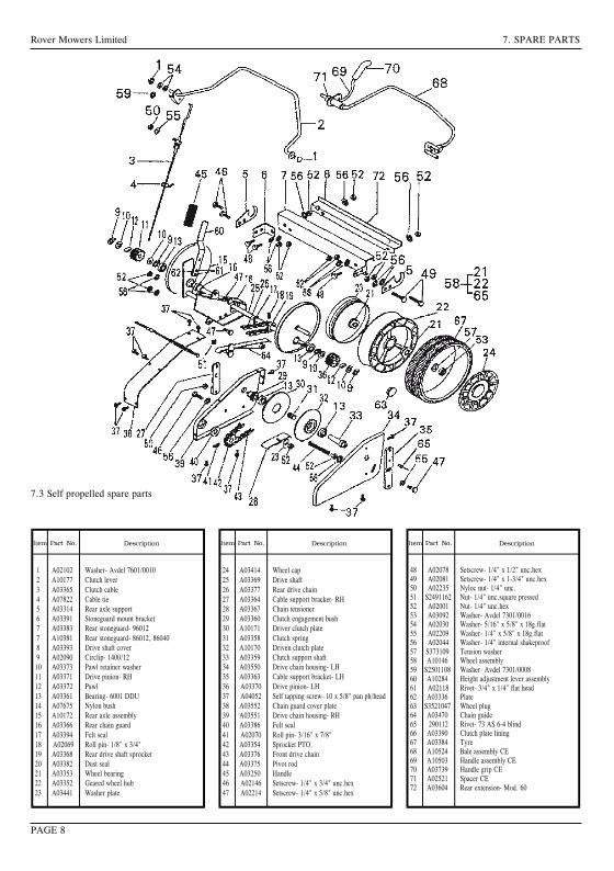
14
25
36
i
A
B
A
B
A
PAGE 11
Rover Mowers Limited
GBSelf propelled drive controlMoved towards (I) turns the clutch on and drives the mower forward.Moved towards (O) turns the clutch off and stops the mowerdriving
DSelbetantriebbetätgungEinstellung auf (I) aktiviert die Kupplung und den Motor vorwärs.Einstellung auf (I) schaltet die kupplung aus und bringt den Mäher zumStehen
FContrôle d'autotractionDéplacé vers (I) enclenche l'embrayage et fait avancer la tondeuse.Déplacé vers (O) décengage l'embrayage el empéche la tondeuse d'avancer
SPAutopropulsado marcas del controlMovido hacia (I) mueve el desembragador y pone a marcha el cortacesped.Movido hacia el (O) apaga el desembragador y para el cortacesped
NLRegulatuur bij relfverplaatsende machinesAls men de knop op (I) zet, is de koppeling ingeschakeld en de machinerijdt vooruit. Als de knop (O) zet, schakelt men de knoppeling uit en
de machine stopt.
ICamando trazione removente
Se mosso verso I (innestato) innesta la frizione e muove in avanti la
faiciatrice tosaerba. Se mosso verso O (disinnestato) disinnesta la
frizione e ferma la trazione della falciatrice tosaerba
GBOperator presense controlHandle moved towards the handle bars, engine and blades are free torotate. Handle released, engine and blades stop rotating
DBedieneranwesenheitakontrolleGiff in Richtung Giffbügel vorgestzt, motor und messer rotieren frei,Griff gelôst, Motor und messer stoppen
FContrôle par opérateurPoigée avancée vers les mancherons, moteur et lames peuvent tourner.Poignée relâchée, moteur arrêtent de tourner
SPOperador de las presencias controlesMango movido hacia manillas, motor y cuchillas estanlibres de hacervucltas. Mango disparado, motor y cuchillas paran de hacer vucltas
NLDodenmanskoop regulatuurknop die aangeeft dat de oparateuraanwezig isDe gasbedieningshendel geplaast in de richting van de hand grepen,de machine loopt en de messen draaien vrij. Gasbedieningshendel isafgezet, de machine stopt, en de messen draaicn neit meer
IComando presenza operatore(I) Manopola mossa verso barre manubrio, motere e lame in posizionelibers e rptanti. (O) manopola disimpegnata. Motre e lame fermi
GBThrottle controlMarked for off, slow and fast positions
DGasbedienungMarkierung aus, langsam sch schnell
FContrôle des gazMarque pour les positions arrêt, ralenti accéléré et
SPControl del acceleradorMarcado por apagado, despacio, rapido posiciones
NLGasknop regulatuurVoorzien van markteken uit, langzaam, snel tekening
IComandeSegno di poizione O staccato lento veloce
3632 Steel Export.PMD11/11/2002, 10:10 AM 2
Rover Mowers Limited7. SPARE PARTS
1A03802Upper handle bars-Mod 602A10016Throttle control assembly3A03581Throttle cable- Quantum4A03557Key start housing5A03560Key start switch6A07679Ignition key7A03741Wiring loom- Mod 60 CE8A03565Cable clamp9A03559Battery10A03558Battery block11A03556Battery support box12A03563Decal- caution13A02083Setscrew- 5/16" x 3/4" unc.hex.14 A02012Washer- 5/16" x 7/8" x 18g.flat15 A02223Nyloc nut- 5/16" unc.16 A02002Speed nut- 3/16" bsw.17 A02163Screw- 3/16" x 1/2" mush/head18 A04060Rivet- 73 AS 5-2
19A03610Foam block2021A10524Bale assembly- Mod 60 CE22A10503Handle assembly Mod.60- CE23A02521Spacer24A03739Handle grip- CE25A03732Cable clip- CE26A03733Rope stop- CE2728A02235Nyloc nut- 1/4" unc.29A04083Screw- 10 x 3/4 pan head3030A03722Brake cable- mod. 6031A03756Switch Plate
7.4 Powerstart spare parts - Series 85000, 86000
PAGE 9
Rover Mowers LimitedENGLISHPREFACE
WARNINGCAUTIONFollow these instructions to avoid mower damage andpossible loss of warranty
The safety of the user and others involved. Personal Injurymay result should this information be disregarded.
CONTENTSPAGE
Preface............................................................................iii
Safety Instructions..........................................................iv
1.Setting up...................................................................11.1Grass catcher assembly...................................1
2.Before operating........................................................12.1Folding handles...............................................12.2Handle bar height............................................12.3Engine lubrication...........................................12.4Fuel..................................................................12.5Controls...........................................................1
3.Operation...................................................................13.1Grass catcher...................................................13.2Adjusting the height of cut..............................13.3To start the engine...........................................13.4To stop the engine...........................................13.5Self propelled mowers.....................................13.6Blade brake control.........................................1
4.Maintenance - General..............................................24.1Engine air cleaner............................................24.2Snorkel air cleaner...........................................24.3Spark Plug.......................................................24.4Cutting assembly.............................................24.5Blade change...................................................24.6Throttle control................................................2
5.Maintenance - self propelled mowers........................25.1Drive chain lubrication....................................25.2Drive chain adjustment....................................25.3Rear drive chain inspection.............................35.4Clutch adjustment............................................35.5Clutch lining inspection..................................35.6Drive pawl lubrication.....................................35.7Drive Wheel Cleaning.....................................3
6.Maintenance powerstart mowers6.1Battery removal...............................................36.2Battery installation..........................................36.3Battery charging..............................................36.4Care and handling............................................3
7.Spare parts.................................................................67.1Series 85000, 86000, 96000 base....................67.2Series 85000, 86000, 96000 bars....................77.3Self-propelled..................................................87.4Powerstart........................................................9
ILLUSTRATIONS.................................................PAGE
Figure 1.Grass catcher assembly...............................iFigure 2.Handle bar height adjustment.....................iFigure 3.Throttle control markings...........................iFigure 4.Operator presence control...........................iFigure 5.Self propelled drive control........................iFigure 6.Grass catcher fitment..................................iFigure 7.Height adjustment......................................iiFigure 8.Blade bolt assembly...................................iiFigure 9.Drive chain cover plate..............................iiFigure 10.Drive chain.................................................iiFigure 11.Drive shaft cover........................................iiFigure 12.Stone cover................................................iiFigure 13.Clutch adjustment......................................iiFigure 14.Drive wheel................................................iiFigure 15.Drive pinion...............................................iiFigure 16.Powerstart control......................................ii
iii
Thank you for buying a Rover Product. All Rover Lawn mowers are designed and constructed to give optimum grass cuttingperformance under normal grass cutting conditions.
This manual covers the operation and maintenance of the Rover walk behind mower. Please read and understand this ownersmanual, before using the mower.If any point is unclear, contact Rover Mowers Limited or any authorised Rover Mower service dealer.
Rover Mowers Limited reserves the right to make changes of, and add improvements upon, its product at anytime, without noticeor obligation. The Company also reserves the right to discontinue manufacture of any product at its discretion at any time.
To emphasise special information, the words WARNING and CAUTION are used.
Rover Mowers Limited 7. SPARE PARTS
1 A03300 Base 12 A03510 Height adjustment rack 13 A03456 Rear Flap 14 A03325 Spring- rear flap 15 A03455 Handle- rear flap 16 A03126 Pivot bush 27 A10148 Conbar assembly 18 A02591 Conbar spring 19 A03515 Axle bracket- RH. 110 A03514 Axle bracket- LH. 111 A03516 Clamp bolt 212 A02051 Woodruff key 113 A01486 Disc boss 114 A00293 Disc assembly 115 A01716 Backplate 116 A03830 Blade- standard 416 A03930 Blade- Mulch N Catch17 A00673 Blade bolt kit 218 A10154 Disc bolt kit 119 A10140 Front axle assembly- professional 119 A10527 Front axle assembly- professional 120 A03450 Front axle bush 221 A03459 Wheel seal 422 A03320 Front wheel assembly 223 A03353 Wheel bearing 824 A03414 Wheel cap 425 A03306 Pivot rod 126 A03743 Decal- Warning 1
27 A03492 Decal- sound level 128 A03409 Nameplate 129 373109 Tension washer 430 A03092 Ratchet plate 431 S2501116 Ratchet plate 232 290112 Poprivet- 73 AS 6-4 blind 1033 A02127 Taptite- 3/8" - 16 HWH x 1" Ind.hex.W/H Duo. 334 * Decal- Model 135 A04052 Self tapping screw- 10 x 5/8" pan ph/head236 A03549 Cable clip 137 A03323 Plug chain slot- model 50 138 A010141 Rear axle assembly- model 50 139 A03313 Rear axle bush- model 50 240 A03250 Plastic handle 141 A10284 Height adj. lever assembly 142 A03336 Packing plate 143 A02066 Rivet 244 A03319 Rear wheel assembly 245 A03303 Grass deflector 146 A10381 Rear stoneguard- Mod. 50 146 A03604 Rear stoneguard- Mod. 60 147 A02071 Rivet- 73 SS 4-3 248 A02235 Nyloc nut- 1/4" unc. 249 A03472 Decal- turbothrust 150 A03927 Nose comb 151 A04108 Rivet 252 A04099 Washer- 3/16" x 3/4" 253 A04111 Screw 2
7.1 Series 85000, 86000 and 96000 base spare parts
PAGE 6
26
Rover Mowers Limited ENGLISH 4. MAINTENANCE GENERAL
5. MAINTENANCE - Self propelled mowers
5.1 Drive chain lubrication
1. Remove the spark plug lead.2. Remove the cover plate screws (a) and lift off the cover plate (b).
Figure 9.3. Support the rear wheels off the ground to enable the drive to be
rotated.4. Use SAE 30 oil and lubricate the drive chains at point (a) whilst
the chain is being rotated. Figure 10.5. Replace the chain cover plate and secure.6. Replace the spark plug lead.
5.2 Drive chain adjustment
Front drive chain1. Remove the spark plug lead.2. Remove the cover plate.3. Loosen the chain tensioner bolt (b) and move the chain tensioner to
give a 3 mm deflection on the drive chain. Figure 10.4. Tighten the chain tensioner bolt and rotate the drive wheels to check
the drive chain for tight spots.5. Replace the cover plate.
Rear drive chain1. Remove the spark plug lead.2. Loosen the rear drive chain tension nut (c) and slide it upwards to
tighten the rear drive chain. Figure 9.3. Retighten the rear drive chain tensioner nut and rotate the rear drive
wheels to check for tight spots.4. Replace the spark plug lead.
5.3 Rear drive chain inspection
1. Remove the spark plug lead.2. Remove the drive shaft cover plate retaining screws (a) and remove
cover plate (b). Figure 11.3. Remove the stone guard retaining screws (c) and remove the stone
guard. Figure 11.4. Remove the chain guard nuts (d) and slide the chain guard out of the
way. Figure 12.5. Inspect the drive chain and axle sprocket and replace if found to have
excessive wear.6. Replace the stone guard and drive shaft axle plate.7. Replace the spark plug lead.
5.4 Clutch adjustment
1. Remove the spark plug lead.2. Loosen the locknut (a) and turn the adjuster (b) clockwise until the
clutch is felt to drag. Figure 13.3. Back off the adjuster anti-clockwise 2-3 turns and retighten locknut
(a).4. Replace the spark plug lead.
4.1 Engine air cleaner
Refer to the engine manufacture's instructions for detailed cleaninginstructions.The engine air cleaner element must be serviced after each 25 hours ofnormal mowing. The element must be serviced more regularly if themower is used in dusty conditions.
4.2 Snorkel air intake
The snorkel air cleaner element must be serviced after each 50 hours ofnormal mowing. The element must be serviced more regularly if themower is used in dusty conditions.
1. Disconnect the air tube from the element holder.2. Remove the holder cap.3. Remove the cartridge and tap gently on a flat surface to remove dirt.4. Replace element in holder and replace holder cap.5. Replace the air tube to the bottom of the element holder.
NOTE: Quantum engines fitted with a Remote snorkel airintake are not fitted with an air cleaner element. Note theair cleaner element on this model is located on the engine.
CAUTION
Do not allow dirt to enter the air tube, engine damage may occur.Check the condition of the air tube regularly and replace ifdamaged.
4.3 Spark plug
For best results remove and check the condition of the spark plug every25 hours of use.
1. Stop the engine and remove the spark plug lead.2. Clean dirt from around the spark plug and remove the spark plug.3. If a new spark plug is required use a Champion RJ19LM or
equivalent and set the electrode gap at 0.7 to 0.8 mm.4. Screw the spark plug into the engine and tighten to 20NM.
4.4 Cutting assembly
1. Disconnect the spark plug lead.2. Move the height of cut lever to the high cut position, and fold the
handle bars.3. Tilt the mower so that the spark plug is up.4. Inspect the cutting assembly for damage and wear.5. Check the disc retaining bolts. Tighten the centre bolt to 48 Nm.and
the three concentric bolts to 14 Nm.6. Return mower to its normal position and replace the spark plug lead.
WARNING
Remove the spark plug lead before working on cutting assembly.Do not work on the cutting assembly without wearing gloves.
4.5 Blade change
1. Disconnect the spark plug lead.2. Set the mower to the high cut position.3. Lift the rear flap on rear catcher mowers and prop open the flap to
give access to the blades.Tilt utility mowers so that the spark plug is up.
4. Remove the blade, blade retaining bolts, nuts and washers anddiscard. Retain only the ‘D’ plates.
5. Fit new blades, blade bolts, washers, and nuts in sets to maintainbalance. Figure 8.
6. Tighten the blade nuts to 16 NM. Check the blades are free to movewhen the blade nut is tensioned.
7. Remove the flap prop or lower the mower to the ground and replacethe spark plug lead.
4.6 Throttle control
Each 25 hours of mowing use a small amount of light oil to lubricatethe throttle control lever.
Page 2
CAUTION
Do not over tighten the spark plug as engine damage may occur.
Rover Mowers Limited 7. SPARE PARTS
PAGE 8
1 A02102 Washer- Avdel 7601/00102 A10177 Clutch lever3 A03365 Clutch cable4 A07822 Cable tie5 A03314 Rear axle support6 A03391 Stoneguard mount bracket7 A03383 Rear stoneguard- 960127 A10381 Rear stoneguard- 86012, 860408 A03393 Drive shaft cover9 A02090 Circlip- 1400/1210 A03373 Pawl retainer washer11 A03371 Drive pinion- RH12 A03372 Pawl13 A03361 Bearing- 6001 DDU14 A07675 Nylon bush15 A10172 Rear axle assembly16 A03366 Rear chain guard17 A03394 Felt seal18 A02069 Roll pin- 1/8" x 3/4"19 A03368 Rear drive shaft sprocket20 A03382 Dust seal21 A03353 Wheel bearing22 A03352 Geared wheel hub23 A03441 Washer plate
24 A03414 Wheel cap25 A03369 Drive shaft26 A03377 Rear drive chain27 A03364 Cable support bracket- RH28 A03367 Chain tensioner29 A03360 Clutch engagement bush30 A10171 Driver clutch plate31 A03358 Clutch spring32 A10170 Driven clutch plate33 A03359 Clutch support shaft34 A03550 Drive chain housing- LH35 A03363 Cable support bracket- LH36 A03370 Drive pinion- LH37 A04052 Self tapping screw- 10 x 5/8" pan ph/head38 A03552 Chain guard cover plate39 A03551 Drive chain housing- RH40 A03386 Felt seal41 A02070 Roll pin- 3/16" x 7/8"42 A03354 Sprocket PTO.43 A03376 Front drive chain44 A03375 Pivot rod45 A03250 Handle46 A02146 Setscrew- 1/4" x 3/4" unc.hex47 A02214 Setscrew- 1/4" x 5/8" unc.hex
48 A02078 Setscrew- 1/4" x 1/2" unc.hex49 A02081 Setscrew- 1/4" x 1-3/4" unc.hex50 A02235 Nyloc nut- 1/4" unc.51 S2491162 Nut- 1/4" unc.square pressed52 A02001 Nut- 1/4" unc.hex53 A03092 Washer- Avdel 7301/001654 A02030 Washer- 5/16" x 5/8" x 18g.flat55 A02209 Washer- 1/4" x 5/8" x 18g.flat56 A02044 Washer- 1/4" internal shakeproof57 S373109 Tension washer58 A10146 Wheel assembly59 S2501108 Washer- Avdel 7301/000860 A10284 Height adjustment lever assembly61 A02118 Rivet- 3/4" x 1/4" flat head62 A03336 Plate63 S3521047 Wheel plug64 A03470 Chain guide65 290112 Rivet- 73 AS 6-4 blind66 A03390 Clutch plate lining67 A03384 Tyre68 A10524 Bale assembly CE69 A10503 Handle assembly CE70 A03739 Handle grip CE71 A02521 Spacer CE72 A03604 Rear extension- Mod. 60
7.3 Self propelled spare parts
Rover Mowers Limited ENGLISH SAFETY INSTRUCTIONS
Safety Instructions1. Training
a. Read the instructions carefully. Be familiar with thecontrols and the proper use of the equipment.
b. Never allow children or people unfamiliar with theseinstructions to use the mower. Local regulations mayrestrict the age of the operator.
c. Never mow while people, especially children, or petsare nearby.
d. Keep in mind that the operator or user is responsiblefor accidents or hazards occurring to other people ortheir property.
2. Preparation
a. While mowing, always wear substantial footwear andlong trousers.Do not operate the equipment when barefoot orwearing open sandals.
b. Thoroughly inspect the area where the equipment isto be used and remove all stones, sticks, wires,bones and other foreign objects.
c. WARNING- Petrol is highly flammable.
Take the following precautions.i. Store fuel in containers specially designed for this
purpose.ii. Refuel outdoors only and do not smoke whilerefuelling.iii. Add fuel before starting the engine. Never remove
the cap of the fuel tank or add petrol while the engineis running or when the engine is hot.iv. If petrol is spilled, do not attempt to start theengine but move the machine away from the area ofspillage and avoid creating any source of ignitionuntil petrol vapours have dissipated.v. For reasons of safety the petrol tank and tank cap lock must be
replaced if damaged.d. Replace faulty silencers.e. Before using, always visually inspect to see that the
blades, blade bolts and cutter assembly are not worn ordamaged. Replace worn or damaged blades in sets topreserve balance.
f. On multibladed machines, take care as rotating oneblade can cause other blades to rotate.
3. Operation
a. Do not operate the engine in a confined space wheredangerous carbon monoxide fumes can collect.
b. Mow only in daylight or in good artificial light.c. Avoid operating the equipment in wet grass, where
feasible.d. Always be sure of your footing on slopes.e. Walk, never run.f. For wheeled rotary machines, mow across the face of
slopes, never up and down.g. Exercise extreme caution when changing direction on
slopes.
h. Do not mow excessively steep slopes.i. Use extreme caution when reversing or pulling the
mower towards you.j. Stop the blade(s) ,if the mower has to be tilted for
transportation when crossing surfaces other than grassand when transporting the mower to and from the areato be mowed.
k. Never operate the mower with defective guards orshields, or without safety devices, for example deflectorsand/or grass catchers in place.
l. Do not change the engine governor settings or overspeedthe engine.
m. Disengage all blade and drive clutches before startingthe engine.
n. Start the engine or switch on the mower carefullyaccording to instructions and with feet well awayfrom the blade(s).
o. Do not tilt when starting the engine or switching onthe motor, unless the mower has to be tilted forstarting. In this case, do not tilt it more than absolutelynecessary and lift only the part which is away from theoperator.
p. Do not start the engine when standing in front of thedischarge chute.
q. Do not put hands or feet near or under rotating parts.Keep clear of the discharge opening at all times.
r. Never pick up or carry a mower while the engine isrunning.
s. Stop the engine and disconnect the spark plug lead:i. Before clearing blockages or unclogging the chute.ii. Before checking, cleaning or working on the mower.iii. After striking a foreign object. Inspect the mower for
damage and make repairs before restarting andoperating the mower.
iv. If the mower starts to vibrate abnormally checkimmediately.
t. Stop the enginei. Whenever you leave the mower.ii. Before refuelling.
u. Reduce the throttle setting during engine run-out and ifthe engine is provided with a shut-off valve, turn off thefuel at the conclusion of mowing.
4. Maintenance and storage.
a. Keep all nuts, bolts, and screws tight to be sure theequipment is in safe working condition.
b. Never store the equipment with petrol in the tank insidea building where fumes may reach an open flame orspark.
c. Allow the engine to cool before storing in any enclosure.d. To reduce the fire hazard, keep the engine, silencer,
battery compartment and petrol storage area free ofgrass, leaves, or excessive grease.
e. Check the grass catcher frequently for wear ordeterioration.
f. Replace worn or damaged parts for safety.g. If the fuel tank has to be drained, do this outdoors.
iv
3632 Imposed PDF's.indd 3 18/05/2006 2:36:10 PM
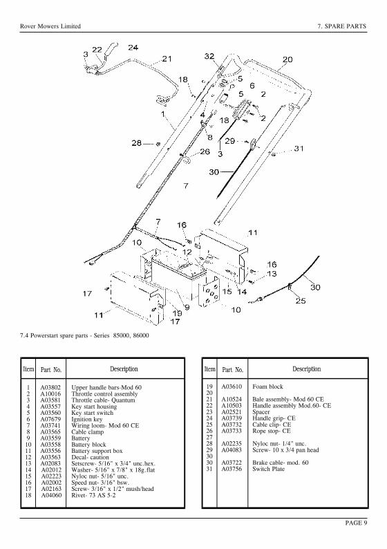
1 4
2 5
3 6
i
A
B
A
B
A
PAGE 11
Rover Mowers Limited
GB Self propelled drive controlMoved towards (I) turns the clutch on and drives the mower forward.Moved towards (O) turns the clutch off and stops the mowerdriving
D SelbetantriebbetätgungEinstellung auf (I) aktiviert die Kupplung und den Motor vorwärs.Einstellung auf (I) schaltet die kupplung aus und bringt den Mäher zumStehen
F Contrôle d'autotractionDéplacé vers (I) enclenche l'embrayage et fait avancer la tondeuse.Déplacé vers (O) décengage l'embrayage el empéche la tondeuse d'avancer
SP Autopropulsado marcas del controlMovido hacia (I) mueve el desembragador y pone a marcha el cortacesped.Movido hacia el (O) apaga el desembragador y para el cortacesped
NL Regulatuur bij relfverplaatsende machinesAls men de knop op (I) zet, is de koppeling ingeschakeld en de machinerijdt vooruit. Als de knop (O) zet, schakelt men de knoppeling uit en
de machine stopt.
I Camando trazione removente
Se mosso verso I (innestato) innesta la frizione e muove in avanti la
faiciatrice tosaerba. Se mosso verso O (disinnestato) disinnesta la
frizione e ferma la trazione della falciatrice tosaerba
GB Operator presense controlHandle moved towards the handle bars, engine and blades are free torotate. Handle released, engine and blades stop rotating
D BedieneranwesenheitakontrolleGiff in Richtung Giffbügel vorgestzt, motor und messer rotieren frei,Griff gelôst, Motor und messer stoppen
F Contrôle par opérateurPoigée avancée vers les mancherons, moteur et lames peuvent tourner.Poignée relâchée, moteur arrêtent de tourner
SP Operador de las presencias controlesMango movido hacia manillas, motor y cuchillas estanlibres de hacervucltas. Mango disparado, motor y cuchillas paran de hacer vucltas
NL Dodenmanskoop regulatuurknop die aangeeft dat de oparateuraanwezig isDe gasbedieningshendel geplaast in de richting van de hand grepen,de machine loopt en de messen draaien vrij. Gasbedieningshendel isafgezet, de machine stopt, en de messen draaicn neit meer
I Comando presenza operatore(I) Manopola mossa verso barre manubrio, motere e lame in posizionelibers e rptanti. (O) manopola disimpegnata. Motre e lame fermi
GB Throttle controlMarked for off, slow and fast positions
D GasbedienungMarkierung aus, langsam sch schnell
F Contrôle des gazMarque pour les positions arrêt, ralenti accéléré et
SP Control del acceleradorMarcado por apagado, despacio, rapido posiciones
NL Gasknop regulatuurVoorzien van markteken uit, langzaam, snel tekening
I ComandeSegno di poizione O staccato lento veloce
3632 Steel Export.PMD 11/11/2002, 10:10 AM2
Rover Mowers Limited 7. SPARE PARTS
1 A03802 Upper handle bars-Mod 602 A10016 Throttle control assembly3 A03581 Throttle cable- Quantum4 A03557 Key start housing5 A03560 Key start switch6 A07679 Ignition key7 A03741 Wiring loom- Mod 60 CE8 A03565 Cable clamp9 A03559 Battery10 A03558 Battery block11 A03556 Battery support box12 A03563 Decal- caution13 A02083 Setscrew- 5/16" x 3/4" unc.hex.14 A02012 Washer- 5/16" x 7/8" x 18g.flat15 A02223 Nyloc nut- 5/16" unc.16 A02002 Speed nut- 3/16" bsw.17 A02163 Screw- 3/16" x 1/2" mush/head18 A04060 Rivet- 73 AS 5-2
19 A03610 Foam block2021 A10524 Bale assembly- Mod 60 CE22 A10503 Handle assembly Mod.60- CE23 A02521 Spacer24 A03739 Handle grip- CE25 A03732 Cable clip- CE26 A03733 Rope stop- CE2728 A02235 Nyloc nut- 1/4" unc.29 A04083 Screw- 10 x 3/4 pan head3030 A03722 Brake cable- mod. 6031 A03756 Switch Plate
7.4 Powerstart spare parts - Series 85000, 86000
PAGE 9
Rover Mowers Limited ENGLISH PREFACE
WARNING CAUTIONFollow these instructions to avoid mower damage andpossible loss of warranty
The safety of the user and others involved. Personal Injurymay result should this information be disregarded.
CONTENTS PAGE
Preface ............................................................................ iii
Safety Instructions .......................................................... iv
1. Setting up ................................................................... 11.1 Grass catcher assembly ................................... 1
2. Before operating ........................................................ 12.1 Folding handles ............................................... 12.2 Handle bar height ............................................ 12.3 Engine lubrication ........................................... 12.4 Fuel .................................................................. 12.5 Controls ........................................................... 1
3. Operation ................................................................... 13.1 Grass catcher ................................................... 13.2 Adjusting the height of cut .............................. 13.3 To start the engine ........................................... 13.4 To stop the engine ........................................... 13.5 Self propelled mowers ..................................... 13.6 Blade brake control ......................................... 1
4. Maintenance - General .............................................. 24.1 Engine air cleaner ............................................ 24.2 Snorkel air cleaner ........................................... 24.3 Spark Plug ....................................................... 24.4 Cutting assembly ............................................. 24.5 Blade change ................................................... 24.6 Throttle control ................................................ 2
5. Maintenance - self propelled mowers ........................ 25.1 Drive chain lubrication .................................... 25.2 Drive chain adjustment.................................... 25.3 Rear drive chain inspection ............................. 35.4 Clutch adjustment ............................................ 35.5 Clutch lining inspection .................................. 35.6 Drive pawl lubrication ..................................... 35.7 Drive Wheel Cleaning ..................................... 3
6. Maintenance powerstart mowers6.1 Battery removal ............................................... 36.2 Battery installation .......................................... 36.3 Battery charging .............................................. 36.4 Care and handling............................................ 3
7. Spare parts ................................................................. 67.1 Series 85000, 86000, 96000 base .................... 67.2 Series 85000, 86000, 96000 bars .................... 77.3 Self-propelled .................................................. 87.4 Powerstart ........................................................ 9
ILLUSTRATIONS ................................................. PAGE
Figure 1. Grass catcher assembly ............................... iFigure 2. Handle bar height adjustment ..................... iFigure 3. Throttle control markings ........................... iFigure 4. Operator presence control ........................... iFigure 5. Self propelled drive control ........................ iFigure 6. Grass catcher fitment .................................. iFigure 7. Height adjustment ...................................... iiFigure 8. Blade bolt assembly ................................... iiFigure 9. Drive chain cover plate .............................. iiFigure 10. Drive chain ................................................. iiFigure 11. Drive shaft cover ........................................ iiFigure 12. Stone cover ................................................ iiFigure 13. Clutch adjustment ...................................... iiFigure 14. Drive wheel ................................................ iiFigure 15. Drive pinion ............................................... iiFigure 16. Powerstart control ...................................... ii
iii
Thank you for buying a Rover Product. All Rover Lawn mowers are designed and constructed to give optimum grass cuttingperformance under normal grass cutting conditions.
This manual covers the operation and maintenance of the Rover walk behind mower. Please read and understand this ownersmanual, before using the mower.If any point is unclear, contact Rover Mowers Limited or any authorised Rover Mower service dealer.
Rover Mowers Limited reserves the right to make changes of, and add improvements upon, its product at anytime, without noticeor obligation. The Company also reserves the right to discontinue manufacture of any product at its discretion at any time.
To emphasise special information, the words WARNING and CAUTION are used.
Rover Mowers Limited7. SPARE PARTS
1A03300Base12A03510Height adjustment rack13A03456Rear Flap14A03325Spring- rear flap15A03455Handle- rear flap16A03126Pivot bush27A10148Conbar assembly18A02591Conbar spring19A03515Axle bracket- RH.110A03514Axle bracket- LH.111A03516Clamp bolt212A02051Woodruff key113A01486Disc boss114A00293Disc assembly115A01716Backplate116A03830Blade- standard416A03930Blade- Mulch N Catch17A00673Blade bolt kit218A10154Disc bolt kit119A10140Front axle assembly- professional119A10527Front axle assembly- professional120A03450Front axle bush221A03459Wheel seal422A03320Front wheel assembly223A03353Wheel bearing824A03414Wheel cap425A03306Pivot rod126A03743Decal- Warning1
27A03492Decal- sound level128A03409Nameplate129373109Tension washer430A03092Ratchet plate431S2501116Ratchet plate232290112Poprivet- 73 AS 6-4 blind1033A02127Taptite- 3/8" - 16 HWH x 1" Ind.hex.W/H Duo.334 *Decal- Model135A04052Self tapping screw- 10 x 5/8" pan ph/head236A03549Cable clip137A03323Plug chain slot- model 50138A010141Rear axle assembly- model 50139A03313Rear axle bush- model 50240A03250Plastic handle141A10284Height adj. lever assembly142A03336Packing plate143A02066Rivet244A03319Rear wheel assembly245A03303Grass deflector146A10381Rear stoneguard- Mod. 50146A03604Rear stoneguard- Mod. 60147A02071Rivet- 73 SS 4-3248A02235Nyloc nut- 1/4" unc.249A03472Decal- turbothrust150A03927Nose comb151A04108Rivet252A04099Washer- 3/16" x 3/4"253A04111Screw2
7.1 Series 85000, 86000 and 96000 base spare parts
PAGE 6
26
Rover Mowers Limited ENGLISH4. MAINTENANCE GENERAL
5. MAINTENANCE - Self propelled mowers
5.1 Drive chain lubrication
1.Remove the spark plug lead.2.Remove the cover plate screws (a) and lift off the cover plate (b).
Figure 9.3.Support the rear wheels off the ground to enable the drive to be
rotated.4.Use SAE 30 oil and lubricate the drive chains atpoint (a) whilst
the chain is being rotated. Figure 10.5.Replace the chain cover plate and secure.6.Replace the spark plug lead.
5.2 Drive chain adjustment
Front drive chain1.Remove the spark plug lead.2.Remove the cover plate.3.Loosen the chain tensioner bolt (b) and move the chain tensioner to
give a 3 mm deflection on the drive chain. Figure 10.4.Tighten the chain tensioner bolt and rotate the drive wheels to check
the drive chain for tight spots.5.Replace the cover plate.
Rear drive chain1.Remove the spark plug lead.2.Loosen the rear drive chain tension nut (c) and slide it upwards to
tighten the rear drive chain. Figure 9.3.Retighten the rear drive chain tensioner nut and rotate the rear drive
wheels to check for tight spots.4.Replace the spark plug lead.
5.3 Rear drive chain inspection
1.Remove the spark plug lead.2.Remove the drive shaft cover plate retaining screws (a) and remove
cover plate (b). Figure 11.3.Remove the stone guard retaining screws (c) and remove the stone
guard. Figure 11.4.Remove the chain guard nuts (d) and slide the chain guard out of the
way. Figure 12.5.Inspect the drive chain and axle sprocket and replace if found to have
excessive wear.6.Replace the stone guard and drive shaft axle plate.7.Replace the spark plug lead.
5.4 Clutch adjustment
1.Remove the spark plug lead.2.Loosen the locknut (a) and turn the adjuster (b) clockwise until the
clutch is felt to drag. Figure 13.3.Back off the adjuster anti-clockwise 2-3 turns and retighten locknut
(a).4.Replace the spark plug lead.
4.1 Engine air cleaner
Refer to the engine manufacture's instructions for detailed cleaninginstructions.The engine air cleaner element must be serviced after each 25 hours ofnormal mowing. The element must be serviced more regularly if themower is used in dusty conditions.
4.2 Snorkel air intake
The snorkel air cleaner element must be serviced after each 50 hours ofnormal mowing. The element must be serviced more regularly if themower is used in dusty conditions.
1.Disconnect the air tube from the element holder.2.Remove the holder cap.3.Remove the cartridge and tap gently on a flat surface to remove dirt.4.Replace element in holder and replace holder cap.5.Replace the air tube to the bottom of the element holder.
NOTE: Quantum engines fitted with a Remote snorkel airintake are not fitted with an air cleaner element. Notetheair cleaner element on this model is located on the engine.
CAUTION
Do not allow dirt to enter the air tube, engine damage may occur.Check the condition of the air tube regularly and replace ifdamaged.
4.3 Spark plug
For best results remove and check the condition of the spark plug every25 hours of use.
1.Stop the engine and remove the spark plug lead.2.Clean dirt from around the spark plug and remove the spark plug.3.If a new spark plug is required use a Champion RJ19LM or
equivalent and set the electrode gap at 0.7 to 0.8 mm.4.Screw the spark plug into the engine and tighten to 20NM.
4.4 Cutting assembly
1.Disconnect the spark plug lead.2.Move the height of cut lever to the high cut position, and fold the
handle bars.3.Tilt the mower so that the spark plug is up.4.Inspect the cutting assembly for damage and wear.5.Check the disc retaining bolts. Tighten the centre bolt to 48 Nm.and
the three concentric bolts to 14 Nm.6.Return mower to its normal position and replace the spark plug lead.
WARNING
Remove the spark plug lead before working on cutting assembly.Do not work on the cutting assembly without wearing gloves.
4.5 Blade change
1.Disconnect the spark plug lead.2.Set the mower to the high cut position.3.Lift the rear flap on rear catcher mowers and prop open the flap to
give access to the blades.Tilt utility mowers so that the spark plug is up.
4.Remove the blade, blade retaining bolts, nuts and washers anddiscard. Retain only the ‘D’ plates.
5.Fit new blades, blade bolts, washers, and nuts in sets to maintainbalance. Figure 8.
6.Tighten the blade nuts to 16 NM. Check the blades are free to movewhen the blade nut is tensioned.
7.Remove the flap prop or lower the mower to the ground and replacethe spark plug lead.
4.6 Throttle control
Each 25 hours of mowing use a small amount of light oil to lubricatethe throttle control lever.
Page 2
CAUTION
Do not over tighten the spark plug as engine damage may occur.
Rover Mowers Limited7. SPARE PARTS
PAGE 8
1A02102Washer- Avdel 7601/00102A10177Clutch lever3A03365Clutch cable4A07822Cable tie5A03314Rear axle support6A03391Stoneguard mount bracket7A03383Rear stoneguard- 960127A10381Rear stoneguard- 86012, 860408A03393Drive shaft cover9A02090Circlip- 1400/1210A03373Pawl retainer washer11A03371Drive pinion- RH12A03372Pawl13A03361Bearing- 6001 DDU14A07675Nylon bush15A10172Rear axle assembly16A03366Rear chain guard17A03394Felt seal18 A02069Roll pin- 1/8" x 3/4"19A03368Rear drive shaft sprocket20A03382Dust seal21A03353Wheel bearing22A03352Geared wheel hub23A03441Washer plate
24A03414Wheel cap25A03369Drive shaft26A03377Rear drive chain27A03364Cable support bracket- RH28A03367Chain tensioner29A03360Clutch engagement bush30A10171Driver clutch plate31A03358Clutch spring32A10170Driven clutch plate33A03359Clutch support shaft34A03550Drive chain housing- LH35A03363Cable support bracket- LH36 A03370Drive pinion- LH37 A04052Self tapping screw- 10 x 5/8" pan ph/head38A03552Chain guard cover plate39A03551Drive chain housing- RH40A03386Felt seal41 A02070Roll pin- 3/16" x 7/8"42A03354Sprocket PTO.43A03376Front drive chain44A03375Pivot rod45A03250Handle46 A02146Setscrew- 1/4" x 3/4" unc.hex47 A02214Setscrew- 1/4" x 5/8" unc.hex
48 A02078Setscrew- 1/4" x 1/2" unc.hex49 A02081Setscrew- 1/4" x 1-3/4" unc.hex50 A02235Nyloc nut- 1/4" unc.51 S2491162Nut- 1/4" unc.square pressed52 A02001Nut- 1/4" unc.hex53 A03092Washer- Avdel 7301/001654 A02030Washer- 5/16" x 5/8" x 18g.flat55 A02209Washer- 1/4" x 5/8" x 18g.flat56 A02044Washer- 1/4" internal shakeproof57S373109Tension washer58A10146Wheel assembly59S2501108Washer- Avdel 7301/000860A10284Height adjustment lever assembly61 A02118Rivet- 3/4" x 1/4" flat head62A03336Plate63S3521047Wheel plug64A03470Chain guide65 290112Rivet- 73 AS 6-4 blind66A03390Clutch plate lining67A03384Tyre68A10524Bale assembly CE69A10503Handle assembly CE70A03739Handle grip CE71A02521Spacer CE72A03604Rear extension- Mod. 60
7.3 Self propelled spare parts
Rover Mowers LimitedENGLISHSAFETY INSTRUCTIONS
Safety Instructions1. Training
a.Read the instructions carefully. Be familiar with thecontrols and the proper use of the equipment.
b.Never allow children or people unfamiliar with theseinstructions to use the mower. Local regulations mayrestrict the age of the operator.
c.Never mow while people, especially children, or petsare nearby.
d.Keep in mind that the operator or user is responsiblefor accidents or hazards occurring to other people ortheir property.
2.Preparation
a.While mowing, always wear substantial footwear andlong trousers.Do not operate the equipment when barefoot orwearing open sandals.
b.Thoroughly inspect the area where the equipment isto be used and remove all stones, sticks, wires,bones and other foreign objects.
c.WARNING- Petrol is highly flammable.
Take the following precautions.i.Store fuel in containers specially designed for this
purpose.ii.Refuel outdoors only and do not smoke whilerefuelling.iii.Add fuel before starting the engine. Never remove
the cap of the fuel tank or add petrol while the engineis running or when the engine is hot.iv.If petrol is spilled, do not attempt to start theengine but move the machine away from the area ofspillage and avoid creating any source of ignitionuntil petrol vapours have dissipated.v.For reasons of safety the petrol tank and tank cap lock must be
replaced if damaged.d.Replace faulty silencers.e.Before using, always visually inspect to see that the
blades, blade bolts and cutter assembly are not worn ordamaged. Replace worn or damaged blades in sets topreserve balance.
f.On multibladed machines, take care as rotating oneblade can cause other blades to rotate.
3.Operation
a.Do not operate the engine in a confined space wheredangerous carbon monoxide fumes can collect.
b.Mow only in daylight or in good artificial light.c.Avoid operating the equipment in wet grass, where
feasible.d.Always be sure of your footing on slopes.e.Walk, never run.f.For wheeled rotary machines, mow across the face of
slopes, never up and down.g.Exercise extreme caution when changing direction on
slopes.
h.Do not mow excessively steep slopes.i.Use extreme caution when reversing or pulling the
mower towards you.j.Stop the blade(s) ,if the mower has to be tilted for
transportation when crossing surfaces other than grassand when transporting the mower to and from the areato be mowed.
k.Never operate the mower with defective guards orshields, or without safety devices, for example deflectorsand/or grass catchers in place.
l.Do not change the engine governor settings or overspeedthe engine.
m.Disengage all blade and drive clutches before startingthe engine.
n.Start the engine or switch on the mower carefullyaccording to instructions and with feet well awayfrom the blade(s).
o.Do not tilt when starting the engine or switching onthe motor, unless the mower has to be tilted forstarting. In this case, do not tilt it more than absolutelynecessary and lift only the part which is away from theoperator.
p.Do not start the engine when standing in front of thedischarge chute.
q.Do not put hands or feet near or under rotating parts.Keep clear of the discharge opening at all times.
r.Never pick up or carry a mower while the engine isrunning.
s.Stop the engine and disconnect the spark plug lead:i.Before clearing blockages or unclogging the chute.ii.Before checking, cleaning or working on the mower.iii.After striking a foreign object. Inspect the mower for
damage and make repairs before restarting andoperating the mower.
iv.If the mower starts to vibrate abnormally checkimmediately.
t.Stop the enginei.Whenever you leave the mower.ii.Before refuelling.
u.Reduce the throttle setting during engine run-out and ifthe engine is provided with a shut-off valve, turn off thefuel at the conclusion of mowing.
4. Maintenance and storage.
a.Keep all nuts, bolts, and screws tight to be sure theequipment is in safe working condition.
b.Never store the equipment with petrol in the tank insidea building where fumes may reach an open flame orspark.
c.Allow the engine to cool before storing in any enclosure.d.To reduce the fire hazard, keep the engine, silencer,
battery compartment and petrol storage area free ofgrass, leaves, or excessive grease.
e.Check the grass catcher frequently for wear ordeterioration.
f.Replace worn or damaged parts for safety.g.If the fuel tank has to be drained, do this outdoors.
iv
3632 Imposed PDF's.indd 218/05/2006 2:36:08 PM
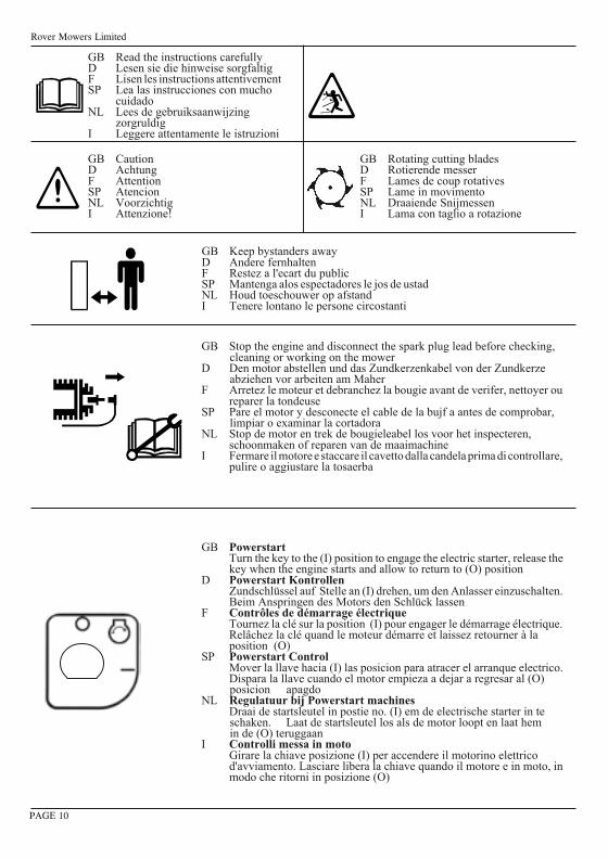
8 13
7 12
9 14
10 15
11 16
ii
A
1mm
Rover Mowers Limited
GB Keep bystanders awayD Andere fernhaltenF Restez a l'ecart du publicSP Mantenga alos espectadores le jos de ustadNL Houd toeschouwer op afstandI Tenere lontano le persone circostanti
GB Rotating cutting bladesD Rotierende messerF Lames de coup rotativesSP Lame in movimentoNL Draaiende SnijmessenI Lama con taglio a rotazione
GB PowerstartTurn the key to the (I) position to engage the electric starter, release thekey when the engine starts and allow to return to (O) position
D Powerstart KontrollenZundschlüssel auf Stelle an (I) drehen, um den Anlasser einzuschalten.Beim Anspringen des Motors den Schlück lassen
F Contrôles de démarrage électriqueTournez la clé sur la position (I) pour engager le démarrage électrique.Relâchez la clé quand le moteur démarre et laissez retourner à laposition (O)
SP Powerstart ControlMover la llave hacia (I) las posicion para atracer el arranque electrico.Dispara la llave cuando el motor empieza a dejar a regresar al (O)posicion apagdo
NL Regulatuur bij Powerstart machinesDraai de startsleutel in postie no. (I) em de electrische starter in teschaken. Laat de startsleutel los als de motor loopt en laat hemin de (O) teruggaan
I Controlli messa in motoGirare la chiave posizione (I) per accendere il motorino elettricod'avviamento. Lasciare libera la chiave quando il motore e in moto, inmodo che ritorni in posizione (O)
GB CautionD AchtungF AttentionSP AtencionNL VoorzichtigI Attenzione!
GB Stop the engine and disconnect the spark plug lead before checking,cleaning or working on the mower
D Den motor abstellen und das Zundkerzenkabel von der Zundkerzeabziehen vor arbeiten am Maher
F Arretez le moteur et debranchez la bougie avant de verifer, nettoyer oureparer la tondeuse
SP Pare el motor y desconecte el cable de la bujf a antes de comprobar,limpiar o examinar la cortadora
NL Stop de motor en trek de bougieleabel los voor het inspecteren,schoonmaken of reparen van de maaimachine
I Fermare il motore e staccare il cavetto dalla candela prima di controllare,pulire o aggiustare la tosaerba
PAGE 10
GB Read the instructions carefullyD Lesen sie die hinweise sorgfaltigF Lisen les instructions attentivementSP Lea las instrucciones con mucho
cuidadoNL Lees de gebruiksaanwijzing
zorgruldigI Leggere attentamente le istruzioni
ROVERMOWERS LIMITED
ACN 000 257 303
Head Office and Factory: Rover Mowers Limited155 Fison Avenue West, Eagle Farm, 4009
Brisbane, Queensland, Australia.
04003632 - CE PRINTED IN AUSTRALIA © Copyright 9/02Revision H.
Para su referencia:
Vendedor .............................................
Fecha de compra ....................................
Modelo ................................................
Serie no ...............................................
Voor uw informatie:
Handelaar .............................................
Aankoopdatum.......................................
Type ...................................................
Serienummer .........................................
Dati da registrare:
Distributore ..........................................
Data d'acquito .......................................
Modello ...............................................
N.o Serie .............................................
For your record:
Dealer .................................................
Date of Purchase ....................................
Model .................................................
Serial No..............................................
Für lhre Aufzeichnung:
Händler ...............................................
Lieferdatum ..........................................
Modell Nr ............................................
Seriennummer .......................................
Pour votre information personnelle:
Fabricant ..............................................
Date d'achat ..........................................
Modèle ................................................
NO de série ...........................................
Recycled paper
GWAIL
Owners ManualGebrauchsanweisungManuel du PropriétaireManual del PropietarioHandleidingManuale Instruzioni
MODEL 50, 60
Petrol LawnmowerMotor-RasenmäherTondeuse à Gazon à EssenceCortadoras de Cesped a GasolinaBenzine GrasmaaimachineFalciatrice A Motore
These machines are covered by one or more of the following Registered Designs and or Patents;Registered Designs: Australia. 131504, 134850Patents: Australia. 713852, 745750, New Zealand. 330293, US. 6085508, UK. GR2325139
04003632-CE PRINTEDINAUSTRALIA ©Copyright1/2003 RevisionI.
3632 Imposed PDF's.indd 1 18/05/2006 2:36:05 PM
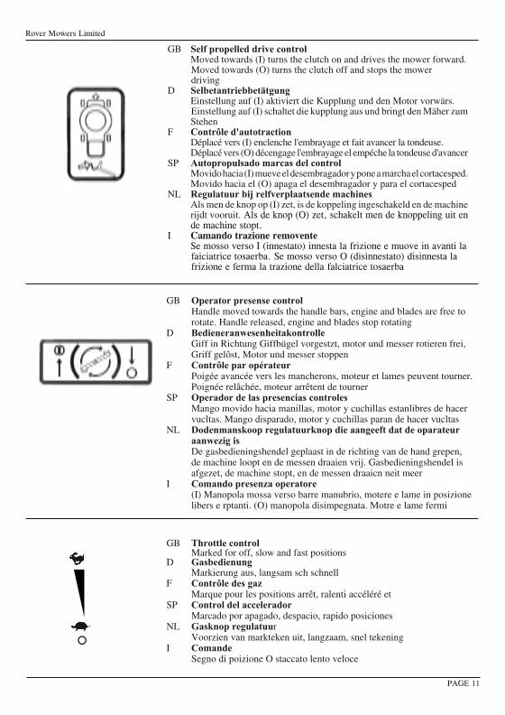