
Report of the IAU Working Group on Cartographic ... · Report of the IAU Working Group on...
35
Celest Mech Dyn Astr DOI 10.1007/s10569-010-9320-4 SPECIAL REPORT Report of the IAU Working Group on Cartographic Coordinates and Rotational Elements: 2009 B. A. Archinal · M. F. A’Hearn · E. Bowell · A. Conrad · G. J. Consolmagno · R. Courtin · T. Fukushima · D. Hestroffer · J. L. Hilton · G. A. Krasinsky · G. Neumann · J. Oberst · P. K. Seidelmann · P. Stooke · D. J. Tholen · P. C. Thomas · I. P. Williams Received: 19 October 2010 / Accepted: 23 October 2010 © Springer Science+Business Media B.V. (outside the USA) 2010 Abstract Every three years the IAU Working Group on Cartographic Coordinates and Rotational Elements revises tables giving the directions of the poles of rotation and the prime meridians of the planets, satellites, minor planets, and comets. This report takes into account the IAU Working Group for Planetary System Nomenclature (WGPSN) and the IAU Committee on Small Body Nomenclature (CSBN) definition of dwarf planets, introduces improved values for the pole and rotation rate of Mercury, returns the rotation rate of Jupiter B. A. Archinal (B ) U.S. Geological Survey, Flagstaff, AZ, USA e-mail: [email protected] M. F. A’Hearn University of Maryland, College Park, MD, USA E. Bowell Lowell Observatory, Flagstaff, AZ, USA A. Conrad W.M. Keck Observatory, Kamuela, HI, USA G. J. Consolmagno Vatican Observatory, Vatican City, Vatican CityState R. Courtin LESIA, Observatoire de Paris, CNRS, Paris, France T. Fukushima National Astronomical Observatory of Japan, Tokyo, Japan D. Hestroffer IMCCE, Observatoire de Paris, CNRS, Paris, France J. L. Hilton U.S. Naval Observatory, Washington, DC, USA G. A. Krasinsky Institute for Applied Astronomy, St. Petersburg, Russia 123
-
Upload
truonglien -
Category
Documents
-
view
219 -
download
0
Transcript of Report of the IAU Working Group on Cartographic ... · Report of the IAU Working Group on...
Celest Mech Dyn AstrDOI 10.1007/s10569-010-9320-4
SPECIAL REPORT
Report of the IAU Working Group on CartographicCoordinates and Rotational Elements: 2009
B. A. Archinal · M. F. A’Hearn · E. Bowell · A. Conrad · G. J. Consolmagno ·R. Courtin · T. Fukushima · D. Hestroffer · J. L. Hilton · G. A. Krasinsky ·G. Neumann · J. Oberst · P. K. Seidelmann · P. Stooke · D. J. Tholen ·P. C. Thomas · I. P. Williams
Received: 19 October 2010 / Accepted: 23 October 2010© Springer Science+Business Media B.V. (outside the USA) 2010
Abstract Every three years the IAU Working Group on Cartographic Coordinates andRotational Elements revises tables giving the directions of the poles of rotation and theprime meridians of the planets, satellites, minor planets, and comets. This report takes intoaccount the IAU Working Group for Planetary System Nomenclature (WGPSN) and the IAUCommittee on Small Body Nomenclature (CSBN) definition of dwarf planets, introducesimproved values for the pole and rotation rate of Mercury, returns the rotation rate of Jupiter
B. A. Archinal (B)U.S. Geological Survey, Flagstaff, AZ, USAe-mail: [email protected]
M. F. A’HearnUniversity of Maryland, College Park, MD, USA
E. BowellLowell Observatory, Flagstaff, AZ, USA
A. ConradW.M. Keck Observatory, Kamuela, HI, USA
G. J. ConsolmagnoVatican Observatory, Vatican City, Vatican City State
R. CourtinLESIA, Observatoire de Paris, CNRS, Paris, France
T. FukushimaNational Astronomical Observatory of Japan, Tokyo, Japan
D. HestrofferIMCCE, Observatoire de Paris, CNRS, Paris, France
J. L. HiltonU.S. Naval Observatory, Washington, DC, USA
G. A. KrasinskyInstitute for Applied Astronomy, St. Petersburg, Russia
123
B. A. Archinal et al.
to a previous value, introduces improved values for the rotation of five satellites of Saturn, andadds the equatorial radius of the Sun for comparison. It also adds or updates size and shapeinformation for the Earth, Mars’ satellites Deimos and Phobos, the four Galilean satellitesof Jupiter, and 22 satellites of Saturn. Pole, rotation, and size information has been added forthe asteroids (21) Lutetia, (511) Davida, and (2867) Šteins. Pole and rotation information hasbeen added for (2) Pallas and (21) Lutetia. Pole and rotation and mean radius informationhas been added for (1) Ceres. Pole information has been updated for (4) Vesta. The highprecision realization for the pole and rotation rate of the Moon is updated. Alternative ori-entation models for Mars, Jupiter, and Saturn are noted. The Working Group also reaffirmsthat once an observable feature at a defined longitude is chosen, a longitude definition originshould not change except under unusual circumstances. It is also noted that alternative coor-dinate systems may exist for various (e.g. dynamical) purposes, but specific cartographiccoordinate system information continues to be recommended for each body. The WorkingGroup elaborates on its purpose, and also announces its plans to occasionally provide limitedupdates to its recommendations via its website, in order to address community needs forsome updates more often than every 3 years. Brief recommendations are also made to thegeneral planetary community regarding the need for controlled products, and improved orconsensus rotation models for Mars, Jupiter, and Saturn.
Keywords Cartographic coordinates · Longitude · Latitude · Rotation axes ·Rotation periods · Sizes · Shapes · Planets · Satellites · Dwarf planets · Minor planets ·Comets
1 Introduction
The IAU Working Group on Cartographic Coordinates and Rotational Elements of the Plan-ets and Satellites was established as a consequence of resolutions adopted by Commis-sions 4 and 16 at the IAU General Assembly at Grenoble in 1976. The Working Groupbecame a joint working group of the IAU and the International Association of Geodesy(IAG) in 1985. Due to a lack of formal communication with the IAG in recent years
G. NeumannNASA Goddard Space Flight Center, Greenbelt, MD, USA
J. OberstDLR Berlin Adlershof, Berlin, Germany
P. K. SeidelmannUniversity of Virginia, Charlottesville, VA, USA
P. StookeUniversity of Western Ontario, London, Canada
D. J. TholenUniversity of Hawaii, Honolulu, HI, USA
P. C. ThomasCornell University, Ithaca, NY, USA
I. P. WilliamsQueen Mary University of London, London, UK
123
Report of the IAU Working Group
that affiliation has been dropped for this report. It may be re-established in the future.Currently, within the IAU, the Working Group is a joint working group of Divisions Iand III, and not part of any commissions. The first report of the Working Group waspresented to the General Assembly at Montreal in 1979 and published in the Trans.IAU 17B, 72–79, 1980. The report with appendices was published in Celestial Mechan-ics 22, 205–230, 1980. The guiding principles and conventions that were adopted by theGroup and the rationale for their acceptance were presented in that report and its appen-dices. The second report of the Working Group was published in the Trans. IAU 18B,151–162, 1983, and also in Celestial Mechanics 29, 309–321, 1983. In 2003 the nameof the Working Group was shortened to the Working Group on Cartographic Coordi-nates and Rotational Elements. The following table summarizes the references to all thereports.
Report General Assembly Celestial Mechanics and Dynamical Astronomy
1 Montreal in 1979 22, 205–230 (Davies et al. 1980)2 Patras in 1982 29, 309–321 (Davies et al. 1983)3 New Delhi in 1985 39, 103–113 (Davies et al. 1986)4 Baltimore in 1988 46, 187–204 (Davies et al. 1989)5 Buenos Aires in 1991 53, 377–397 (Davies et al. 1992)6 The Hague in 1994 63, 127–148 (Davies et al. 1996)7 Kyoto in 1997 No report8 Manchester in 2000 82, 83–110 (Seidelmann et al. 2002)9 Sydney in 2003 91, 203–215 (Seidelmann et al. 2005)10 Prague in 2006 98, 155–180 (Seidelmann et al. 2007)11 Rio de Janeiro in 2009 This paper
Reprints and preprints of the previous reports and this report can be found at the WorkingGroup web site: http://astrogeology.usgs.gov/Projects/WGCCRE. Previous reports are alsoavailable at the web site: http://www.springerlink.com/content/100246.
The original impetus for the Working Group was stated in an IAU Resolution: “to avoid aproliferation of inconsistent cartographic and rotational systems, there is a need to define thecartographic and rotational elements of the planets and satellites on a systematic basis and torelate the new cartographic coordinates rigorously to the rotational elements” (InternationalAstronomical Union (IAU) 1977, p. 144). Since its first report (Davies et al. 1980), thisWorking Group has addressed this need and its purpose has remained essentially unchanged,except for the recognition of the need to address the same issues for small bodies of the SolarSystem, beginning with the 2003 report.
Therefore in actual execution, the Working Group sees its mission as this: making rec-ommendations that define and relate the coordinate systems of Solar System bodies to theirrotational elements to support making cartographic products (i.e. “mapping”) of such bod-ies. The working group incorporates any reasonable and peer reviewed improved determina-tions that follow previously established conventions, or possibly in some cases may decidebetween different such determinations. Because of the lack of the necessary resources, how-ever, the Working Group does not verify or validate such determinations. Our recommen-dations are from the Working Group alone and, if only for reasons of practicality, are notrecommendations from the full IAU. The Working Group has no “enforcement” mecha-nism to assure that its recommendations are followed—the value of these recommendationsis only from their development by international consensus and adoption by the planetarycommunity.
123
B. A. Archinal et al.
The main use of these recommendations should be in cases where standardization is use-ful. It is, of course, not our intention to limit science or the state of the art. If for cartographicor other purposes these recommendations can be followed without affecting the quality ofthe product, then they should be followed so that products can be more easily comparedand multiple datasets appropriately registered. If a user has sufficient data to update the rec-ommended models or values used so that any cartographic product would be significantlyimproved, then obviously—following the conventions described here—such updates shouldbe used. (It may also be useful to make alternative products using old and new models forcomparison purposes).
Because there will inevitably be some delay before our next triennial report is published(or our website updated—see below), this type of action is almost always necessary whenupdated parameter estimates are derived. We encourage the publication of such updates in thepeer-reviewed literature at the earliest opportunity. This is desirable both so that the WorkingGroup can consider them and as appropriate recommend their use and properly referencethem in our next report, but also so others will become aware of such updates, and can usethem if necessary in the interim.
At the request of various individuals and missions, in the coming triennium the WorkingGroup will consider providing limited updates to its recommendations via its website. Thisis in order to address a cited need to update recommendations more often than every 3 years,e.g. for use by operational missions and for updated cartographic products. Details of thisprocedure are still to be worked out. However, our tentative plan is to determine approxi-mately every 6 months whether such updates are necessary and, if so, announce them onour web site. We also plan to begin listing on the website—without any recommendationsand for information purposes only—new recently published and (preferably) peer-revieweddeterminations related to Solar System coordinate systems. Note that the posting of recom-mendations to our web site is not intended to supersede the need for our triennial reports.We plan to reserve the bulk of any new recommendations or changes to our recommenda-tions for these reports, only placing time-critical ones on our website. In our next report, wewill consider the usefulness of these procedures and whether they should continue. Input forsuch updates (whether for Working Group consideration or information only) and commenton these procedures from the community is welcome, particularly from missions and otherworking groups.
The 2003 report introduced and recommended a consistent system of coordinates for bothminor planets (asteroids) and comets, and in this report we extend it to cover dwarf planets.This system is not the same as the system for planets and satellites, which was not changed.It is recognized that the existence of two different systems has the potential for confusion,but the methods required for dwarf planets, minor planets, their satellites, and comets differsufficiently to justify the use of two different systems. This report includes descriptions ofthe two systems; one for planets and satellites (Sects. 2, 3, 4, 6) and another for dwarf planets,minor planets, their satellites, and comets (Sects. 5 and 7). Rotational elements (body orien-tation in inertial space) are covered first (Sects. 2–5), and then cartographic coordinates, e.g.latitude, longitude, and body shape (Sects. 6, 7). Brief recommendations from the WorkingGroup complete this report (Sect. 8). For the purpose of assigning bodies such as Pluto andCeres to these tables, this report assumes that dwarf planets are the primary bodies on thelist maintained by the IAU Working Group for Planetary System Nomenclature (WGPSN)and the IAU Committee on Small Body Nomenclature (CSBN) (2010). The Appendix listschanges made since the previous report.
123
Report of the IAU Working Group
2 Definition of Rotational Elements for Planets and Satellites
Planetary coordinate systems are defined relative to their mean axis of rotation and var-ious definitions of longitude depending on the body. The longitude systems of most ofthose bodies with observable rigid surfaces have been defined by references to a sur-face feature such as a crater. Approximate expressions for these rotational elements withrespect to the International Celestial Reference Frame (ICRF) (Ma et al. 1998) have beenderived. The ICRF is the reference frame of the International Celestial Reference Sys-tem and is itself epochless. There is a small (well under 0.1 arcsecond) rotation betweenthe ICRF and the mean dynamical frame of J2000.0. The epoch J2000.0, which is JD2451545.0 (2000 January 1 12 hours), TDB, is the epoch for variable quantities, which areexpressed in units of days (86400 SI seconds) or Julian centuries of 36525 days. Barycen-tric Dynamical Time (TDB) is the reference time scale for time dependent variables. TDBwas clarified in definition at the IAU General Assembly of 2006 in Prague. TDB, some-times called Teph, is roughly equivalent to Terrestrial Time (TT) in epoch and rate. UTC,TCB, and TCG differ from TT in epoch and rate. For more information on reference sys-tems and time scales see Kovalevsky and Seidelmann (2004), http://www.iers.org, http://rorf.usno.navy.mil/ICRF/, or http://www.usno.navy.mil/USNO/astronomical-applications/astronomical-information-center/icrs-narrative.
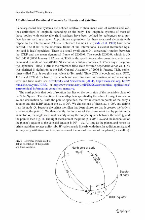
The north pole is that pole of rotation that lies on the north side of the invariable plane ofthe Solar System. The direction of the north pole is specified by the value of its right ascensionα0 and declination δ0. With the pole so specified, the two intersection points of the body’sequator and the ICRF equator are α0 ± 90◦. We choose one of these, α0 + 90◦, and defineit as the node Q. Suppose the prime meridian has been chosen so that it crosses the body’sequator at the point B. We then specify the location of the prime meridian by providing avalue for W, the angle measured easterly along the body’s equator between the node Q andthe point B (see Fig. 1). The right ascension of the pointQ is 90◦ +α0 and the inclination ofthe planet’s equator to the celestial equator is 90◦ − δ0. As long as the planet, and hence itsprime meridian, rotates uniformly,W varies nearly linearly with time. In addition, α0,δ0, andW may vary with time due to a precession of the axis of rotation of the planet (or satellite).
Fig. 1 Reference system used todefine orientation of the planetsand their satellites North pole of body
Equatorof body
ICRF equator
B
Prime
m
eridian
(α0, δ
0)
ϒ
90˚- δ0Q
W
90+α
0
123
B. A. Archinal et al.
If W increases with time, the planet has a direct (or prograde) rotation, and, if W decreaseswith time, the rotation is said to be retrograde.
In the absence of other information, since most satellites fall into this category, the axis ofrotation is assumed to be normal to the mean orbital plane of the planet or the satellite. Formany of the satellites, it is assumed that the rotation rate is equal to the mean orbital period(i.e. synchronous rotation), but in some cases such an assumption still needs to be validated.
The angle W specifies the ephemeris position of the prime meridian. For planets or sat-ellites without any accurately observable fixed surface features, the adopted expression forW defines the prime meridian and is not subject to correction for this reason. However, therotation rate may be redefined for other reasons. Where possible, however, the cartographicposition of the prime meridian is defined by a suitable observable feature, and so the con-stants in the expression W = W0 + Wd , where d is the interval in days from the standardepoch, are chosen so that the ephemeris position follows the motion of the cartographicposition as closely as possible; in these cases the expression for W may require emendationin the future. When new higher accuracy mapping is done, the longitude of the fixed featureshould be maintained and a new value forW0 derived, the results published in peer-reviewedliterature, and the result reported to this Working Group for possible adoption. For bodieswhere they are in use, longitude defining features are noted in the footnotes to Tables 1, 2,and 3.
The Working Group would like to emphasize—as it did in the introduction to its first report(Davies et al. 1980, p. 73)—that once an observable feature at a defined longitude is chosen,the longitude definition origin should not change except under unusual circumstances (suchas perhaps a change in or loss of the feature). This implies that once such a feature has beenadopted, a return to a value of W0 defined by some other method (e.g. the principal axes ofinertia for resonantly or synchronously rotating bodies such as Mercury (Margot 2009), orJovian or Saturnian satellites) should be avoided. Note, however, that this does not precludethe use of smaller or more precisely determined features, multiple features, or even humanartifacts to define longitude—as long as the original definition is maintained to within theaccuracy of previous determinations. An example is the redefinition of the origin for longi-tude for Mars from the large feature then known as Sinus Meridiani to the small crater Airy-0(de Vaucouleurs et al. 1973).
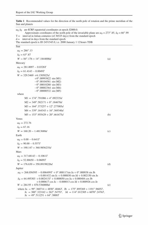
Recommended values of the constants in the expressions for α0, δ0, and W , in celestialequatorial coordinates, are given for the planets and satellites in Tables 1 and 2. In general,these expressions should be accurate to one-tenth of a degree; however, two decimal placesare given to assure consistency when changing coordinates systems. Zeros have sometimesbeen added to rate values (W ) for computational consistency and are not an indication ofsignificant accuracy. Additional decimal places are given in the expressions for Mercury, theMoon, Mars, Saturn, and Uranus, reflecting the greater confidence in their accuracy. Expres-sions for the Sun and Earth are given to a similar precision as those of the other bodies of theSolar System and are for comparative purposes only.
These recommendations are not intended to imply that other coordinate systems with dif-ferent rotational elements should not be used for planetary bodies for other than cartographicor provisional purposes. For example it is recognized that the use of dynamical coordinatesystems such as those tied to a body’s principal axis may be needed for computational pur-poses or for important dynamical work. The use of such coordinate systems is common,for example as described immediately below for the Moon, and also for Mercury (Margot2009). It is also possible, depending for example on the observational mode and accuracy,that a body fixed coordinate frame can at times be defined relative to inertial space at a higherlevel of accuracy than to a surface feature fixed frame. Mercury is again an example, where
123
Report of the IAU Working Group
Table 1 Recommended values for the direction of the north pole of rotation and the prime meridian of theSun and planets
α0,δ0 are ICRF equatorial coordinates at epoch J2000.0.Approximate coordinates of the north pole of the invariable plane are α0 = 273◦.85, δ0 = 66◦.99
T = interval in Julian centuries (of 36525 days) from the standard epochd = interval in days from the standard epochThe standard epoch is JD 2451545.0, i.e. 2000 January 1 12 hours TDB
Sun
α0 = 286◦.13
δ0 = 63◦.87
W = 84◦.176 + 14◦.1844000d (a)
Mercury
α0 = 281.0097 − 0.0328T
δ0 = 61.4143 − 0.0049T
W = 329.5469 +6.1385025d+0◦.00993822 sin (M1)−0◦.00104581 sin (M2)−0◦.00010280 sin (M3)−0◦.00002364 sin (M4)−0◦.00000532 sin (M5)
where
M1 = 174◦.791086 + 4◦.092335d
M2 = 349◦.582171 + 8◦.184670d
M3 = 164◦.373257 + 12◦.277005d
M4 = 339◦.164343 + 16◦.369340d
M5 = 153◦.955429 + 20◦.461675d (b)
Venus
α0 = 272.76
δ0 = 67.16
W = 160.20 − 1.4813688d (c)
Earth
α0 = 0.00 − 0.641T
δ0 = 90.00 − 0.557T
W = 190.147 + 360.9856235d
Mars
α0 = 317.68143 − 0.1061T
δ0 = 52.88650 − 0.0609T
W = 176.630 + 350.89198226d (d)
Jupiter
α0 = 268.056595 − 0.006499T + 0◦.000117sin Ja + 0◦.000938 sin Jb+ 0.001432 sin Jc + 0.000030 sin Jd + 0.002150 sin Je
δ0 = 64.495303 + 0.002413T + 0.000050 cos Ja + 0.000404 cos Jb+ 0.000617 cos Jc − 0.000013 cos Jd + 0.000926 cos Je
W = 284.95 + 870.5360000d (e)
where Ja = 99◦.360714 + 4850◦.4046T , Jb = 175◦.895369 + 1191◦.9605T ,Jc = 300◦.323162 + 262◦.5475T , Jd = 114◦.012305 + 6070◦.2476T ,Je = 49◦.511251 + 64◦.3000T
123
B. A. Archinal et al.
Table 1 continued
Saturn
α0 = 40.589 − 0.036T
δ0 = 83.537 − 0.004T
W = 38.90 + 810.7939024d (e)
Uranus
α0 = 257.311
δ0 = −15.175
W = 203.81 − 501.1600928d (e)
Neptune
α0 = 299.36 + 0.70 sin N
δ0 = 43.46 − 0.51 cos N
W = 253.18 + 536.3128492d − 0.48 sin N (e)
N = 357.85 + 52.316T
(a) The equation W for the Sun is now corrected for light travel time and removing the aberration correction.See the Appendix in Seidelmann et al. (2007)(b) The 20◦ meridian is defined by the crater Hun Kal(c) The 0◦ meridian is defined by the central peak in the crater Ariadne(d) The 0◦ meridian is defined by the crater Airy-0(e) The equations for W for Jupiter, Saturn, Uranus and Neptune refer to the rotation of their magnetic fields(System III). On Jupiter, System I (WI = 67◦.1 + 877◦.900d) refers to the mean atmospheric equatorialrotation; System II (WII = 43◦.3 + 870◦.270d) refers to the mean atmospheric rotation north of the southcomponent of the north equatorial belt, and south of the north component of the south equatorial belt
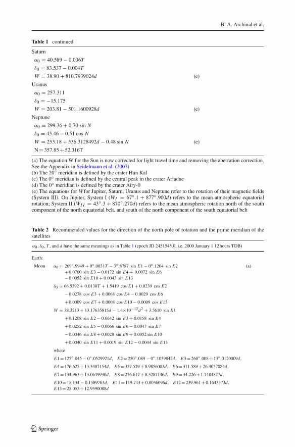
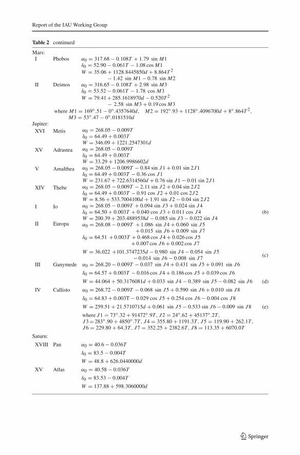
Table 2 Recommended values for the direction of the north pole of rotation and the prime meridian of thesatellites
α0, δ0, T , and d have the same meanings as in Table 1 (epoch JD 2451545.0, i.e. 2000 January 1 12 hours TDB)
Earth:
Moon α0 = 269◦.9949 + 0◦.0031T − 3◦.8787 sin E1 − 0◦.1204 sin E2 (a)+ 0.0700 sin E3 − 0.0172 sin E4 + 0.0072 sin E6− 0.0052 sin E10 + 0.0043 sin E13
δ0 = 66.5392 + 0.0130T + 1.5419 cos E1 + 0.0239 cos E2
− 0.0278 cos E3 + 0.0068 cos E4 − 0.0029 cos E6
+ 0.0009 cos E7 + 0.0008 cos E10 − 0.0009 cos E13
W = 38.3213 + 13.17635815d − 1.4×10⁻¹²d2 + 3.5610 sin E1
+ 0.1208 sin E2 − 0.0642 sin E3 + 0.0158 sin E4
+ 0.0252 sin E5 − 0.0066 sin E6 − 0.0047 sin E7
− 0.0046 sin E8 + 0.0028 sin E9 + 0.0052 sin E10
+ 0.0040 sin E11 + 0.0019 sin E12 − 0.0044 sin E13
where
E1 = 125◦.045 − 0◦.0529921d, E2 = 250◦.089 − 0◦.1059842d, E3 = 260◦.008 + 13◦.0120009d,
E4 = 176.625 + 13.3407154d, E5 = 357.529 + 0.9856003d, E6 = 311.589 + 26.4057084d,
E7 = 134.963 + 13.0649930d, E8 = 276.617 + 0.3287146d, E9 = 34.226 + 1.7484877d,
E10 = 15.134 − 0.1589763d, E11 = 119.743 + 0.0036096d, E12 = 239.961 + 0.1643573d,E13 = 25.053 + 12.9590088d
123
Report of the IAU Working Group
Table 2 continued
Mars:I Phobos α0 = 317.68 − 0.108T + 1.79 sin M1
δ0 = 52.90 − 0.061T − 1.08 cosM1W = 35.06 + 1128.8445850d + 8.864T 2
− 1.42 sin M1 − 0.78 sin M2II Deimos α0 = 316.65 − 0.108T + 2.98 sin M3
δ0 = 53.52 − 0.061T − 1.78 cos M3W = 79.41 + 285.1618970d − 0.520T 2
− 2.58 sin M3 + 0.19 cosM3where M1 = 169◦.51 − 0◦.4357640d, M2 = 192◦.93 + 1128◦.4096700d + 8◦.864T 2,
M3 = 53◦.47 − 0◦.0181510dJupiter:
XVI Metis α0 = 268.05 − 0.009Tδ0 = 64.49 + 0.003TW = 346.09 + 1221.2547301d
XV Adrastea α0 = 268.05 − 0.009Tδ0 = 64.49 + 0.003TW = 33.29 + 1206.9986602d
V Amalthea α0 = 268.05 − 0.009T − 0.84 sin J1 + 0.01 sin 2J1δ0 = 64.49 + 0.003T − 0.36 cos J1W = 231.67 + 722.6314560d + 0.76 sin J1 − 0.01 sin 2J1
XIV Thebe α0 = 268.05 − 0.009T − 2.11 sin J2 + 0.04 sin 2J2δ0 = 64.49 + 0.003T − 0.91 cos J2 + 0.01 cos 2J2W = 8.56 + 533.7004100d + 1.91 sin J2 − 0.04 sin 2J2
I Io α0 = 268.05 − 0.009T + 0.094 sin J3 + 0.024 sin J4δ0 = 64.50 + 0.003T + 0.040 cos J3 + 0.011 cos J4W = 200.39 + 203.4889538d − 0.085 sin J3 − 0.022 sin J4
(b)
II Europa α0 = 268.08 − 0.009T + 1.086 sin J4 + 0.060 sin J5+ 0.015 sin J6 + 0.009 sin J7
δ0 = 64.51 + 0.003T + 0.468 cos J4 + 0.026 cos J5+ 0.007 cos J6 + 0.002 cos J7
W = 36.022 +101.3747235d − 0.980 sin J4 − 0.054 sin J5− 0.014 sin J6 − 0.008 sin J7
(c)
III Ganymede α0 = 268.20 − 0.009T − 0.037 sin J4 + 0.431 sin J5 + 0.091 sin J6
δ0 = 64.57 + 0.003T − 0.016 cos J4 + 0.186 cos J5 + 0.039 cos J6
W = 44.064 + 50.3176081d + 0.033 sin J4 − 0.389 sin J5 − 0.082 sin J6 (d)
IV Callisto α0 = 268.72 − 0.009T − 0.068 sin J5 + 0.590 sin J6 + 0.010 sin J8
δ0 = 64.83 + 0.003T − 0.029 cos J5 + 0.254 cos J6 − 0.004 cos J8
W = 259.51 + 21.5710715d + 0.061 sin J5 − 0.533 sin J6 − 0.009 sin J8 (e)
where J1 = 73◦.32 + 91472◦.9T , J2 = 24◦.62 + 45137◦.2T ,J3 = 283◦.90 + 4850◦.7T , J4 = 355.80 + 1191.3T , J5 = 119.90 + 262.1T ,J6 = 229.80 + 64.3T , J7 = 352.25 + 2382.6T , J8 = 113.35 + 6070.0T
Saturn:
XVIII Pan α0 = 40.6 − 0.036T
δ0 = 83.5 − 0.004T
W = 48.8 + 626.0440000d
XV Atlas α0 = 40.58 − 0.036T
δ0 = 83.53 − 0.004T
W = 137.88 + 598.3060000d
123
B. A. Archinal et al.
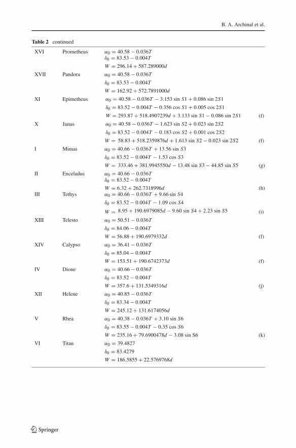
Table 2 continued
XVI Prometheus α0 = 40.58 − 0.036Tδ0 = 83.53 − 0.004T
W = 296.14 + 587.289000d
XVII Pandora α0 = 40.58 − 0.036T
δ0 = 83.53 − 0.004T
W = 162.92 + 572.7891000d
XI Epimetheus α0 = 40.58 − 0.036T − 3.153 sin S1 + 0.086 sin 2S1
δ0 = 83.52 − 0.004T − 0.356 cos S1 + 0.005 cos 2S1
W = 293.87 + 518.4907239d + 3.133 sin S1 − 0.086 sin 2S1 (f)
X Janus α0 = 40.58 − 0.036T − 1.623 sin S2 + 0.023 sin 2S2
δ0 = 83.52 − 0.004T − 0.183 cos S2 + 0.001 cos 2S2
W = 58.83 + 518.2359876d + 1.613 sin S2 − 0.023 sin 2S2 (f)
I Mimas α0 = 40.66 − 0.036T + 13.56 sin S3
δ0 = 83.52 − 0.004T − 1.53 cos S3
W = 333.46 + 381.9945550d − 13.48 sin S3 − 44.85 sin S5 (g)
II Enceladus α0 = 40.66 − 0.036Tδ0 = 83.52 − 0.004T
W = 6.32 + 262.7318996d (h)III Tethys α0 = 40.66 − 0.036T + 9.66 sin S4
δ0 = 83.52 − 0.004T − 1.09 cos S4
W = 8.95 + 190.6979085d − 9.60 sin S4 + 2.23 sin S5 (i)
XIII Telesto α0 = 50.51 − 0.036T
δ0 = 84.06 − 0.004T
W = 56.88 + 190.6979332d (f)
XIV Calypso α0 = 36.41 − 0.036T
δ0 = 85.04 − 0.004T
W = 153.51 + 190.6742373d (f)
IV Dione α0 = 40.66 − 0.036T
δ0 = 83.52 − 0.004T
W = 357.6 + 131.5349316d (j)
XII Helene α0 = 40.85 − 0.036T
δ0 = 83.34 − 0.004T
W = 245.12 + 131.6174056d
V Rhea α0 = 40.38 − 0.036T + 3.10 sin S6
δ0 = 83.55 − 0.004T − 0.35 cos S6
W = 235.16 + 79.6900478d − 3.08 sin S6 (k)
VI Titan α0 = 39.4827
δ0 = 83.4279
W = 186.5855 + 22.5769768d
123
Report of the IAU Working Group
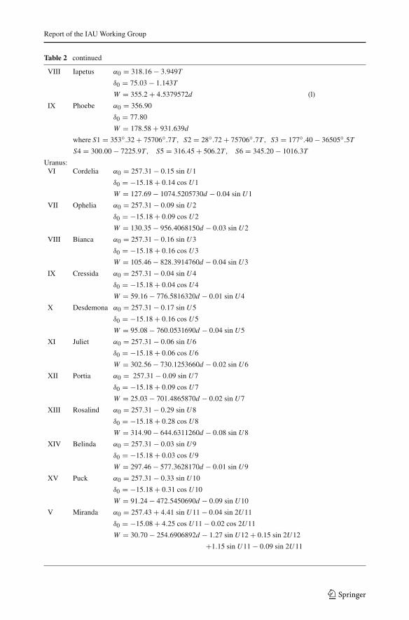
Table 2 continued
VIII Iapetus α0 = 318.16 − 3.949T
δ0 = 75.03 − 1.143T
W = 355.2 + 4.5379572d (l)
IX Phoebe α0 = 356.90
δ0 = 77.80
W = 178.58 + 931.639d
where S1 = 353◦.32 + 75706◦.7T , S2 = 28◦.72 + 75706◦.7T , S3 = 177◦.40 − 36505◦.5TS4 = 300.00 − 7225.9T , S5 = 316.45 + 506.2T , S6 = 345.20 − 1016.3T
Uranus:VI Cordelia α0 = 257.31 − 0.15 sin U1
δ0 = −15.18 + 0.14 cos U1
W = 127.69 − 1074.5205730d − 0.04 sin U1
VII Ophelia α0 = 257.31 − 0.09 sin U2
δ0 = −15.18 + 0.09 cos U2
W = 130.35 − 956.4068150d − 0.03 sin U2
VIII Bianca α0 = 257.31 − 0.16 sin U3
δ0 = −15.18 + 0.16 cos U3
W = 105.46 − 828.3914760d − 0.04 sin U3
IX Cressida α0 = 257.31 − 0.04 sin U4
δ0 = −15.18 + 0.04 cos U4
W = 59.16 − 776.5816320d − 0.01 sin U4
X Desdemona α0 = 257.31 − 0.17 sin U5
δ0 = −15.18 + 0.16 cos U5
W = 95.08 − 760.0531690d − 0.04 sin U5
XI Juliet α0 = 257.31 − 0.06 sin U6
δ0 = −15.18 + 0.06 cos U6
W = 302.56 − 730.1253660d − 0.02 sin U6
XII Portia α0 = 257.31 − 0.09 sin U7
δ0 = −15.18 + 0.09 cos U7
W = 25.03 − 701.4865870d − 0.02 sin U7
XIII Rosalind α0 = 257.31 − 0.29 sin U8
δ0 = −15.18 + 0.28 cos U8
W = 314.90 − 644.6311260d − 0.08 sin U8
XIV Belinda α0 = 257.31 − 0.03 sin U9
δ0 = −15.18 + 0.03 cos U9
W = 297.46 − 577.3628170d − 0.01 sin U9
XV Puck α0 = 257.31 − 0.33 sin U10
δ0 = −15.18 + 0.31 cos U10
W = 91.24 − 472.5450690d − 0.09 sin U10
V Miranda α0 = 257.43 + 4.41 sin U11 − 0.04 sin 2U11
δ0 = −15.08 + 4.25 cos U11 − 0.02 cos 2U11
W = 30.70 − 254.6906892d − 1.27 sin U12 + 0.15 sin 2U12
+1.15 sin U11 − 0.09 sin 2U11
123
B. A. Archinal et al.
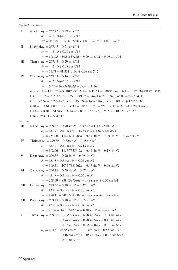
Table 2 continued
I Ariel α0 = 257.43 + 0.29 sin U13
δ0 = −15.10 + 0.28 cos U13
W = 156.22 − 142.8356681d + 0.05 sin U12 + 0.08 sin U13
II Umbrielα0 = 257.43 + 0.21 sin U14
δ0 = −15.10 + 0.20 cos U14
W = 108.05 − 86.8688923d − 0.09 sin U12 + 0.06 sin U14
III Titania α0 = 257.43 + 0.29 sin U15
δ0 = −15.10 + 0.28 cos U15
W = 77.74 − 41.3514316d + 0.08 sin U15
IV Oberon α0 = 257.43 + 0.16 sin U16
δ0 = −15.10 + 0.16 cos U16
W = 6.77 − 26.7394932d + 0.04 sin U16
where U1 = 115◦.75 + 54991◦.87T ,U2 = 141◦.69 + 41887◦.66T , U3 = 135◦.03+29927◦.35T ,
U4 = 61.77 + 25733.59T , U5 = 249.32 + 24471.46T , U6 = 43.86 + 22278.41T ,
U7 = 77.66 + 20289.42T U8 = 157.36 + 16652.76T , U9 = 101.81 + 12872.63T ,
U10 = 138.64 + 8061.81T , U11 = 102.23 − 2024.22T , U12 = 316.41 + 2863.96T ,
U13 = 304.01 − 51.94T , U14 = 308.71 − 93.17T , U15 = 340.82 − 75.32T ,
U16 = 259.14 − 504.81T
Neptune
III Naiad α0 = 299.36 + 0.70 sin N − 6.49 sin N1 + 0.25 sin 2N1
δ0 = 43.36 − 0.51 cos N − 4.75 cos N1 + 0.09 cos 2N1
W = 254.06 + 1222.8441209d − 0.48 sin N + 4.40 sin N1 − 0.27 sin 2N1
IV Thalassa α0 = 299.36 + 0.70 sin N − 0.28 sin N2
δ0 = 43.45 − 0.51 cos N − 0.21 cos N2
W = 102.06 + 1155.7555612d − 0.48 sin N + 0.19 sin N2
V Despina α0 = 299.36 + 0.70sin N − 0.09 sin N3
δ0 = 43.45 − 0.51 cos N − 0.07 cos N3
W = 306.51 + 1075.7341562d − 0.49 sin N + 0.06 sin N3
VI Galatea α0 = 299.36 + 0.70 sin N − 0.07 sin N4
δ0 = 43.43 − 0.51 cos N − 0.05 cos N4
W = 258.09 + 839.6597686d − 0.48 sin N + 0.05 sin N4
VII Larissa α0 = 299.36 + 0.70 sin N − 0.27 sin N5
δ0 = 43.41 − 0.51 cos N − 0.20 cos N5
W = 179.41 + 649.0534470d − 0.48 sin N + 0.19 sin N5
VIII Proteus α0 = 299.27 + 0.70 sin N − 0.05 sin N6
δ0 = 42.91 − 0.51 cos N − 0.04 cos N6
W = 93.38 + 320.7654228d − 0.48 sin N + 0.04 sin N6
I Triton α0 = 299.36 − 32.35 sin N7 − 6.28 sin 2N7 − 2.08 sin 3N7
− 0.74 sin 4N7 − 0.28 sin 5N7 − 0.11 sin 6N7
− 0.07 sin 7N7 − 0.02 sin 8N7 − 0.01 sin 9N7
δ0 = 41.17 + 22.55 cos N7 + 2.10 cos 2N7 + 0.55 cos 3N7
+ 0.16 cos 4N7 + 0.05 cos 5N7 + 0.02 cos 6N7
+ 0.01 cos 7N7
123
Report of the IAU Working Group
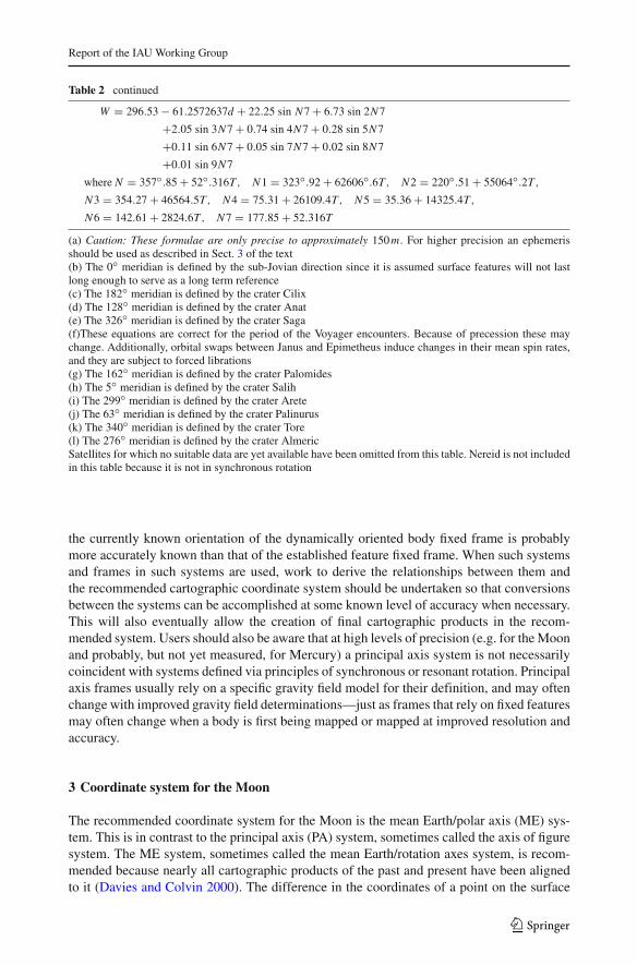
Table 2 continued
W = 296.53 − 61.2572637d + 22.25 sin N7 + 6.73 sin 2N7
+2.05 sin 3N7 + 0.74 sin 4N7 + 0.28 sin 5N7
+0.11 sin 6N7 + 0.05 sin 7N7 + 0.02 sin 8N7
+0.01 sin 9N7
whereN = 357◦.85 + 52◦.316T , N1 = 323◦.92 + 62606◦.6T , N2 = 220◦.51 + 55064◦.2T ,N3 = 354.27 + 46564.5T , N4 = 75.31 + 26109.4T , N5 = 35.36 + 14325.4T ,
N6 = 142.61 + 2824.6T , N7 = 177.85 + 52.316T
(a) Caution: These formulae are only precise to approximately 150m. For higher precision an ephemerisshould be used as described in Sect. 3 of the text(b) The 0◦ meridian is defined by the sub-Jovian direction since it is assumed surface features will not lastlong enough to serve as a long term reference(c) The 182◦ meridian is defined by the crater Cilix(d) The 128◦ meridian is defined by the crater Anat(e) The 326◦ meridian is defined by the crater Saga(f)These equations are correct for the period of the Voyager encounters. Because of precession these maychange. Additionally, orbital swaps between Janus and Epimetheus induce changes in their mean spin rates,and they are subject to forced librations(g) The 162◦ meridian is defined by the crater Palomides(h) The 5◦ meridian is defined by the crater Salih(i) The 299◦ meridian is defined by the crater Arete(j) The 63◦ meridian is defined by the crater Palinurus(k) The 340◦ meridian is defined by the crater Tore(l) The 276◦ meridian is defined by the crater AlmericSatellites for which no suitable data are yet available have been omitted from this table. Nereid is not includedin this table because it is not in synchronous rotation
the currently known orientation of the dynamically oriented body fixed frame is probablymore accurately known than that of the established feature fixed frame. When such systemsand frames in such systems are used, work to derive the relationships between them andthe recommended cartographic coordinate system should be undertaken so that conversionsbetween the systems can be accomplished at some known level of accuracy when necessary.This will also eventually allow the creation of final cartographic products in the recom-mended system. Users should also be aware that at high levels of precision (e.g. for the Moonand probably, but not yet measured, for Mercury) a principal axis system is not necessarilycoincident with systems defined via principles of synchronous or resonant rotation. Principalaxis frames usually rely on a specific gravity field model for their definition, and may oftenchange with improved gravity field determinations—just as frames that rely on fixed featuresmay often change when a body is first being mapped or mapped at improved resolution andaccuracy.
3 Coordinate system for the Moon
The recommended coordinate system for the Moon is the mean Earth/polar axis (ME) sys-tem. This is in contrast to the principal axis (PA) system, sometimes called the axis of figuresystem. The ME system, sometimes called the mean Earth/rotation axes system, is recom-mended because nearly all cartographic products of the past and present have been alignedto it (Davies and Colvin 2000). The difference in the coordinates of a point on the surface
123
B. A. Archinal et al.
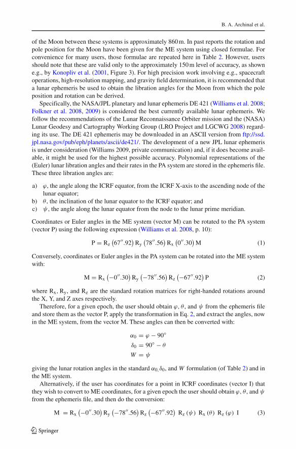
of the Moon between these systems is approximately 860 m. In past reports the rotation andpole position for the Moon have been given for the ME system using closed formulae. Forconvenience for many users, those formulae are repeated here in Table 2. However, usersshould note that these are valid only to the approximately 150 m level of accuracy, as showne.g., by Konopliv et al. (2001, Figure 3). For high precision work involving e.g., spacecraftoperations, high-resolution mapping, and gravity field determination, it is recommended thata lunar ephemeris be used to obtain the libration angles for the Moon from which the poleposition and rotation can be derived.
Specifically, the NASA/JPL planetary and lunar ephemeris DE 421 (Williams et al. 2008;Folkner et al. 2008, 2009) is considered the best currently available lunar ephemeris. Wefollow the recommendations of the Lunar Reconnaissance Orbiter mission and the (NASA)Lunar Geodesy and Cartography Working Group (LRO Project and LGCWG 2008) regard-ing its use. The DE 421 ephemeris may be downloaded in an ASCII version from ftp://ssd.jpl.nasa.gov/pub/eph/planets/ascii/de421/. The development of a new JPL lunar ephemerisis under consideration (Williams 2009, private communication) and, if it does become avail-able, it might be used for the highest possible accuracy. Polynomial representations of the(Euler) lunar libration angles and their rates in the PA system are stored in the ephemeris file.These three libration angles are:
a) ϕ, the angle along the ICRF equator, from the ICRF X-axis to the ascending node of thelunar equator;
b) θ , the inclination of the lunar equator to the ICRF equator; andc) ψ , the angle along the lunar equator from the node to the lunar prime meridian.
Coordinates or Euler angles in the ME system (vector M) can be rotated to the PA system(vector P) using the following expression (Williams et al. 2008, p. 10):
P = Rz(67′′.92
)Ry
(78′′.56
)Rx
(0′′.30
)M (1)
Conversely, coordinates or Euler angles in the PA system can be rotated into the ME systemwith:
M = Rx(−0′′.30
)Ry
(−78′′.56)
Rz(−67′′.92
)P (2)
where Rx,Ry, and Rz are the standard rotation matrices for right-handed rotations aroundthe X, Y, and Z axes respectively.
Therefore, for a given epoch, the user should obtain ϕ, θ , and ψ from the ephemeris fileand store them as the vector P, apply the transformation in Eq. 2, and extract the angles, nowin the ME system, from the vector M. These angles can then be converted with:
α0 = ϕ − 90◦
δ0 = 90◦ − θ
W = ψ
giving the lunar rotation angles in the standard α0,δ0, andW formulation (of Table 2) and inthe ME system.
Alternatively, if the user has coordinates for a point in ICRF coordinates (vector I) thatthey wish to convert to ME coordinates, for a given epoch the user should obtain ϕ, θ , and ψfrom the ephemeris file, and then do the conversion:
M = Rx(−0′′.30
)Ry
(−78′′.56)
Rz(−67′′.92
)Rz (ψ) Rx (θ) Rz (ϕ) I (3)
123
Report of the IAU Working Group
with M now being the coordinates of the point in the ME system. The user should note thatthe numerical values for the rotations in Eqs. 1, 2, and 3 are specific to DE 421 and aredifferent for past and future ephemerides.
Note that the NASA/JPL Navigation and Ancillary Information Facility (NAIF) providessoftware and files to facilitate the above transformations. This includes a Planetary Con-stants Kernel (PCK) made using the lunar libration information extracted from the DE 421ephemeris, and a special lunar frames kernel (FK) providing the specifications and dataneeded to construct the PA to ME system transformation. A new version of the PCK will alsobe provided when a new JPL ephemeris is released. See http://naif.jpl.nasa.gov or (for DE421) http://naif.jpl.nasa.gov/naif/lunar_kernels.txt for further information. Although writtenbefore DE 421 became available, Roncoli (2005) also provides useful information on lunarconstants and coordinates.
4 Rotation elements for planets and satellites
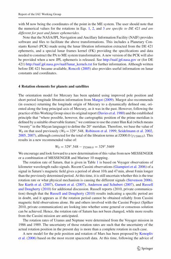
The orientation model for Mercury has been updated using improved pole position andshort period longitude libration information from Margot (2009). Margot also recommends(in essence) returning the longitude origin of Mercury to a dynamically defined one, ori-ented along the long principal axis of Mercury, as it was in the past. However, following thepractice of this Working Group since its original report (Davies et al. 1980) and the establishedprinciple that “where possible, however, the cartographic position of the prime meridian isdefined by a suitable observable feature,” we continue to use the crater Hun Kal (which means“twenty” in the Mayan language) to define the 20◦ meridian. Therefore, we base the value ofW0 on that used previously (W0 = 329◦.548, Robinson et al. 1999; Seidelmann et al. 2002,2005, 2007), although corrected for the total of the libration terms at J2000.0 (γJ2000.0). Thisresults in a new recommended value of:
W0 = 329◦.548 − γJ2000.0 = 329◦.5469
We encourage and look forward to a new determination of this value from new MESSENGERor a combination of MESSENGER and Mariner 10 mapping.
The rotation rate of Saturn, that is given in Table 1 is based on Voyager observations ofkilometer wavelength radio signals. Recent Cassini observations (Giampieri et al. 2006) of asignal in Saturn’s magnetic field gives a period of about 10 h and 47 min, about 8 min longerthan the previously determined period. At this time, it is still uncertain whether this is the truerotation rate or what physical mechanism is causing the different signals (Stevenson 2006).See Kurth et al. (2007), Gurnett et al. (2007), Anderson and Schubert (2007), and Russelland Dougherty (2010) for additional discussion. Russell reports (2010, private communica-tion) though that the Russell and Dougherty (2010) results indicating a specific period arein doubt, and it appears as if the rotation period cannot be obtained reliably from Cassinimagnetic field observations alone. He and others involved with the Cassini Project (Spilker2010, private communication) are looking into whether some general or consensus solutioncan be achieved. Hence, the rotation rate of Saturn has not been changed, while more resultsfrom the Cassini mission are anticipated.
The rotation rates of Uranus and Neptune were determined from the Voyager mission in1986 and 1989. The uncertainty of those rotation rates are such that the uncertainty of theactual rotation position in the present day is more than a complete rotation in each case.
A new model for the pole position and rotation of Mars has been proposed by Konoplivet al. (2006) based on the most recent spacecraft data. At this time, following the advice of
123
B. A. Archinal et al.
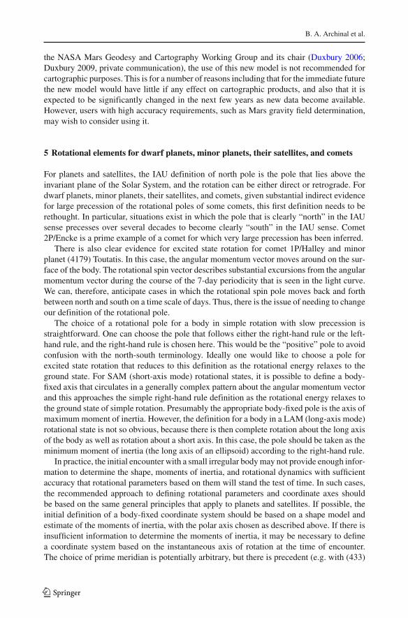
the NASA Mars Geodesy and Cartography Working Group and its chair (Duxbury 2006;Duxbury 2009, private communication), the use of this new model is not recommended forcartographic purposes. This is for a number of reasons including that for the immediate futurethe new model would have little if any effect on cartographic products, and also that it isexpected to be significantly changed in the next few years as new data become available.However, users with high accuracy requirements, such as Mars gravity field determination,may wish to consider using it.
5 Rotational elements for dwarf planets, minor planets, their satellites, and comets
For planets and satellites, the IAU definition of north pole is the pole that lies above theinvariant plane of the Solar System, and the rotation can be either direct or retrograde. Fordwarf planets, minor planets, their satellites, and comets, given substantial indirect evidencefor large precession of the rotational poles of some comets, this first definition needs to berethought. In particular, situations exist in which the pole that is clearly “north” in the IAUsense precesses over several decades to become clearly “south” in the IAU sense. Comet2P/Encke is a prime example of a comet for which very large precession has been inferred.
There is also clear evidence for excited state rotation for comet 1P/Halley and minorplanet (4179) Toutatis. In this case, the angular momentum vector moves around on the sur-face of the body. The rotational spin vector describes substantial excursions from the angularmomentum vector during the course of the 7-day periodicity that is seen in the light curve.We can, therefore, anticipate cases in which the rotational spin pole moves back and forthbetween north and south on a time scale of days. Thus, there is the issue of needing to changeour definition of the rotational pole.
The choice of a rotational pole for a body in simple rotation with slow precession isstraightforward. One can choose the pole that follows either the right-hand rule or the left-hand rule, and the right-hand rule is chosen here. This would be the “positive” pole to avoidconfusion with the north-south terminology. Ideally one would like to choose a pole forexcited state rotation that reduces to this definition as the rotational energy relaxes to theground state. For SAM (short-axis mode) rotational states, it is possible to define a body-fixed axis that circulates in a generally complex pattern about the angular momentum vectorand this approaches the simple right-hand rule definition as the rotational energy relaxes tothe ground state of simple rotation. Presumably the appropriate body-fixed pole is the axis ofmaximum moment of inertia. However, the definition for a body in a LAM (long-axis mode)rotational state is not so obvious, because there is then complete rotation about the long axisof the body as well as rotation about a short axis. In this case, the pole should be taken as theminimum moment of inertia (the long axis of an ellipsoid) according to the right-hand rule.
In practice, the initial encounter with a small irregular body may not provide enough infor-mation to determine the shape, moments of inertia, and rotational dynamics with sufficientaccuracy that rotational parameters based on them will stand the test of time. In such cases,the recommended approach to defining rotational parameters and coordinate axes shouldbe based on the same general principles that apply to planets and satellites. If possible, theinitial definition of a body-fixed coordinate system should be based on a shape model andestimate of the moments of inertia, with the polar axis chosen as described above. If there isinsufficient information to determine the moments of inertia, it may be necessary to definea coordinate system based on the instantaneous axis of rotation at the time of encounter.The choice of prime meridian is potentially arbitrary, but there is precedent (e.g. with (433)
123
Report of the IAU Working Group
Eros) for choosing it so it aligns with the longest axis (or minimum moment of inertia, if thiscan be estimated).
The orientation of the body at subsequent encounters is likely to differ from the predic-tions of a model based on initial encounter data. Such departures may be gross, as a resultof rapid precession in which the spin axis varies relative to the body, or more subtle, simplybecause of the limits of accuracy of the initial observation. In either case, it should be bornein mind that (as for planets and satellites) the main purpose of defining a body-fixed coor-dinate system is to facilitate mapping of surface features. It is, therefore, desirable to relatethe axes of the initial system to identifiable surface features. When new observations becomeavailable, the axes should in most cases be left unchanged with respect to the surface featuresand the rotational model amended to model the inertial-space orientation of the axes moreaccurately. In contrast to the case of planets and satellites, for which the rotation axis is oftendetermined more accurately than the rotation rate, for irregular bodies both axis and rate mayvary over time or be poorly determined. It follows that two or three landmark features willbe required to determine the body-fixed orientation of the coordinate axes, rather than thesingle landmark that suffices to define the prime meridian of a regularly rotating body.
As specified in Sect. 6, for planets and satellites, longitude should increase monotoni-cally for an observer fixed in inertial space. For dwarf planets, minor planets, their satellites,and comets however, with the above rule for poles, this definition corresponds always to aleft-hand rule for increasing longitude, since the concept of retrograde rotation is no longerrelevant. Therefore, for dwarf planets, minor planets, their satellites, and comets, to be consis-tent with the above pole definition, increasing longitude should always follow the right-handrule. This definition is consistent with the sense of increasing longitude used for Eros byMiller et al. (2002), but is inconsistent with the sense of increasing longitude used for Erosby Thomas et al. (2002).
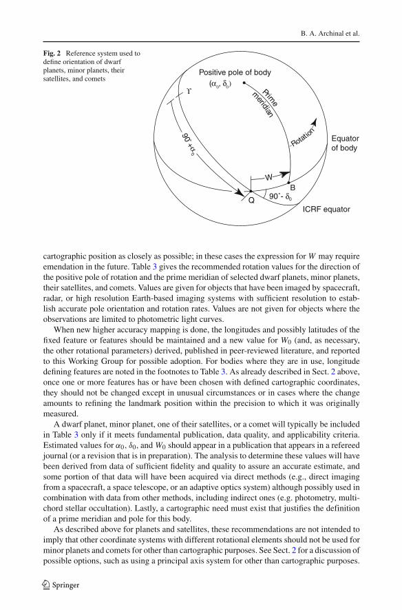
For each such body, the positive pole of rotation is selected as the maximum or minimummoment of inertia according to whether there is short or long axis rotational state and accord-ing to the right-hand rule. So the positive pole is specified by the value of its right ascensionα0 and declination δ0. With the pole so specified, the two intersection points of the body’sequator and the ICRF equator are α0 ± 90◦. We choose one of these, α0 + 90◦, and defineit as the node Q. Suppose the prime meridian has been chosen so that it crosses the body’sequator at the point B. We then specify the location of the prime meridian by providinga value for W, the angle measured along the body’s equator between the node Q and thepoint B in a right-hand system with respect to the body’s positive pole (see Fig. 2). The rightascension of the pointQ is 90◦ +α0 and the inclination of the body’s equator to the celestialequator is 90◦ − δ0. As long as the planet, and hence its prime meridian, rotates uniformly,W varies linearly with time according to the right-hand rule. In addition, α0,, δ0, andW mayvary with time due to a precession of the axis of rotation of the body. It should be noted thatfor bodies whose spin precesses rapidly with large amplitude, this simple formulation of thebody orientation in terms of pole orientation and spin angle may be insufficient. In such casesit may be necessary to develop expressions for the body orientation in terms of a full set oftime-varying Euler angles. At the present time, however, the formulation given here sufficesto represent the rotation of those bodies for which data are available.
The angleW specifies the ephemeris position of the prime meridian, and for dwarf planets,minor planets, their satellites, and comets without any accurately observable fixed surfacefeatures, the adopted expression forW defines the prime meridian. Where possible, however,the cartographic position of the prime meridian is defined by a suitable observable feature,and so the constants in the expression W =W0 + W d , where d is the interval in days fromthe standard epoch, are chosen so that the ephemeris position follows the motion of the
123
B. A. Archinal et al.
Fig. 2 Reference system used todefine orientation of dwarfplanets, minor planets, theirsatellites, and comets
Positive pole of body
Equatorof body
ICRF equator
B
Rotatio
n
Prime
m
eridian
(α0, δ0)
ϒ
90˚- δ0Q
W
90+α
0
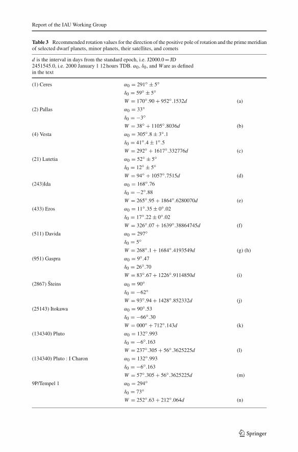
cartographic position as closely as possible; in these cases the expression forW may requireemendation in the future. Table 3 gives the recommended rotation values for the direction ofthe positive pole of rotation and the prime meridian of selected dwarf planets, minor planets,their satellites, and comets. Values are given for objects that have been imaged by spacecraft,radar, or high resolution Earth-based imaging systems with sufficient resolution to estab-lish accurate pole orientation and rotation rates. Values are not given for objects where theobservations are limited to photometric light curves.
When new higher accuracy mapping is done, the longitudes and possibly latitudes of thefixed feature or features should be maintained and a new value for W0 (and, as necessary,the other rotational parameters) derived, published in peer-reviewed literature, and reportedto this Working Group for possible adoption. For bodies where they are in use, longitudedefining features are noted in the footnotes to Table 3. As already described in Sect. 2 above,once one or more features has or have been chosen with defined cartographic coordinates,they should not be changed except in unusual circumstances or in cases where the changeamounts to refining the landmark position within the precision to which it was originallymeasured.
A dwarf planet, minor planet, one of their satellites, or a comet will typically be includedin Table 3 only if it meets fundamental publication, data quality, and applicability criteria.Estimated values for α0, δ0, andW0 should appear in a publication that appears in a refereedjournal (or a revision that is in preparation). The analysis to determine these values will havebeen derived from data of sufficient fidelity and quality to assure an accurate estimate, andsome portion of that data will have been acquired via direct methods (e.g., direct imagingfrom a spacecraft, a space telescope, or an adaptive optics system) although possibly used incombination with data from other methods, including indirect ones (e.g. photometry, multi-chord stellar occultation). Lastly, a cartographic need must exist that justifies the definitionof a prime meridian and pole for this body.
As described above for planets and satellites, these recommendations are not intended toimply that other coordinate systems with different rotational elements should not be used forminor planets and comets for other than cartographic purposes. See Sect. 2 for a discussion ofpossible options, such as using a principal axis system for other than cartographic purposes.
123
Report of the IAU Working Group
Table 3 Recommended rotation values for the direction of the positive pole of rotation and the prime meridianof selected dwarf planets, minor planets, their satellites, and comets
d is the interval in days from the standard epoch, i.e. J2000.0 = JD2451545.0, i.e. 2000 January 1 12 hours TDB. α0, δ0, and Ware as definedin the text
(1) Ceres α0 = 291◦ ± 5◦δ0 = 59◦ ± 5◦W = 170◦.90 + 952◦.1532d (a)
(2) Pallas α0 = 33◦δ0 = −3◦W = 38◦ + 1105◦.8036d (b)
(4) Vesta α0 = 305◦.8 ± 3◦.1δ0 = 41◦.4 ± 1◦.5W = 292◦ + 1617◦.332776d (c)
(21) Lutetia α0 = 52◦ ± 5◦δ0 = 12◦ ± 5◦W = 94◦ + 1057◦.7515d (d)
(243)Ida α0 = 168◦.76
δ0 = −2◦.88
W = 265◦.95 + 1864◦.6280070d (e)
(433) Eros α0 = 11◦.35 ± 0◦.02
δ0 = 17◦.22 ± 0◦.02
W = 326◦.07 + 1639◦.38864745d (f)
(511) Davida α0 = 297◦δ0 = 5◦W = 268◦.1 + 1684◦.4193549d (g) (h)
(951) Gaspra α0 = 9◦.47
δ0 = 26◦.70
W = 83◦.67 + 1226◦.9114850d (i)
(2867) Šteins α0 = 90◦δ0 = −62◦W = 93◦.94 + 1428◦.852332d (j)
(25143) Itokawa α0 = 90◦.53
δ0 = −66◦.30
W = 000◦ + 712◦.143d (k)
(134340) Pluto α0 = 132◦.993
δ0 = −6◦.163
W = 237◦.305 + 56◦.3625225d (l)
(134340) Pluto : I Charon α0 = 132◦.993
δ0 = −6◦.163
W = 57◦.305 + 56◦.3625225d (m)
9P/Tempel 1 α0 = 294◦δ0 = 73◦W = 252◦.63 + 212◦.064d (n)
123
B. A. Archinal et al.
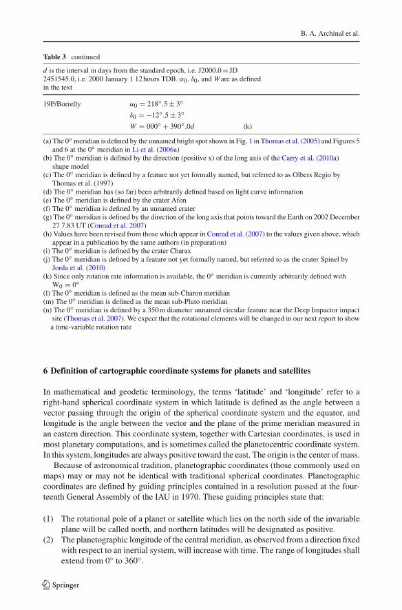
Table 3 continued
d is the interval in days from the standard epoch, i.e. J2000.0 = JD2451545.0, i.e. 2000 January 1 12 hours TDB. α0, δ0, and Ware as definedin the text
19P/Borrelly α0 = 218◦.5 ± 3◦δ0 = −12◦.5 ± 3◦W = 000◦ + 390◦.0d (k)
(a) The 0◦ meridian is defined by the unnamed bright spot shown in Fig. 1 in Thomas et al. (2005) and Figures 5and 6 at the 0◦ meridian in Li et al. (2006a)
(b) The 0◦ meridian is defined by the direction (positive x) of the long axis of the Carry et al. (2010a)shape model
(c) The 0◦ meridian is defined by a feature not yet formally named, but referred to as Olbers Regio byThomas et al. (1997)
(d) The 0◦ meridian has (so far) been arbitrarily defined based on light curve information(e) The 0◦ meridian is defined by the crater Afon(f) The 0◦ meridian is defined by an unnamed crater(g) The 0◦ meridian is defined by the direction of the long axis that points toward the Earth on 2002 December
27 7.83 UT (Conrad et al. 2007)(h) Values have been revised from those which appear in Conrad et al. (2007) to the values given above, which
appear in a publication by the same authors (in preparation)(i) The 0◦ meridian is defined by the crater Charax(j) The 0◦ meridian is defined by a feature not yet formally named, but referred to as the crater Spinel by
Jorda et al. (2010)(k) Since only rotation rate information is available, the 0◦ meridian is currently arbitrarily defined with
W0 = 0◦(l) The 0◦ meridian is defined as the mean sub-Charon meridian(m) The 0◦ meridian is defined as the mean sub-Pluto meridian(n) The 0◦ meridian is defined by a 350 m diameter unnamed circular feature near the Deep Impactor impact
site (Thomas et al. 2007). We expect that the rotational elements will be changed in our next report to showa time-variable rotation rate
6 Definition of cartographic coordinate systems for planets and satellites
In mathematical and geodetic terminology, the terms ‘latitude’ and ‘longitude’ refer to aright-hand spherical coordinate system in which latitude is defined as the angle between avector passing through the origin of the spherical coordinate system and the equator, andlongitude is the angle between the vector and the plane of the prime meridian measured inan eastern direction. This coordinate system, together with Cartesian coordinates, is used inmost planetary computations, and is sometimes called the planetocentric coordinate system.In this system, longitudes are always positive toward the east. The origin is the center of mass.
Because of astronomical tradition, planetographic coordinates (those commonly used onmaps) may or may not be identical with traditional spherical coordinates. Planetographiccoordinates are defined by guiding principles contained in a resolution passed at the four-teenth General Assembly of the IAU in 1970. These guiding principles state that:
(1) The rotational pole of a planet or satellite which lies on the north side of the invariableplane will be called north, and northern latitudes will be designated as positive.
(2) The planetographic longitude of the central meridian, as observed from a direction fixedwith respect to an inertial system, will increase with time. The range of longitudes shallextend from 0◦ to 360◦.
123
Report of the IAU Working Group
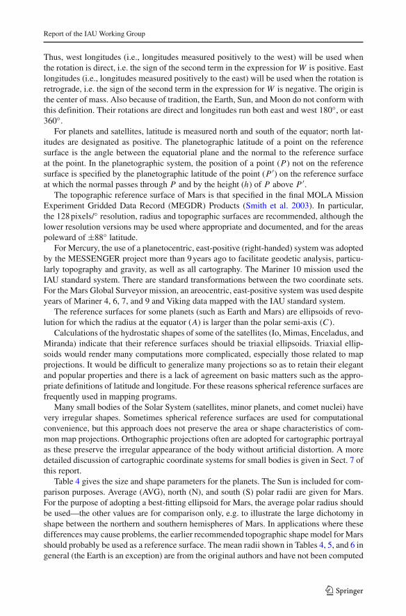
Thus, west longitudes (i.e., longitudes measured positively to the west) will be used whenthe rotation is direct, i.e. the sign of the second term in the expression forW is positive. Eastlongitudes (i.e., longitudes measured positively to the east) will be used when the rotation isretrograde, i.e. the sign of the second term in the expression for W is negative. The origin isthe center of mass. Also because of tradition, the Earth, Sun, and Moon do not conform withthis definition. Their rotations are direct and longitudes run both east and west 180◦, or east360◦.
For planets and satellites, latitude is measured north and south of the equator; north lat-itudes are designated as positive. The planetographic latitude of a point on the referencesurface is the angle between the equatorial plane and the normal to the reference surfaceat the point. In the planetographic system, the position of a point (P ) not on the referencesurface is specified by the planetographic latitude of the point (P ′) on the reference surfaceat which the normal passes through P and by the height (h) of P above P ′.
The topographic reference surface of Mars is that specified in the final MOLA MissionExperiment Gridded Data Record (MEGDR) Products (Smith et al. 2003). In particular,the 128 pixels/◦ resolution, radius and topographic surfaces are recommended, although thelower resolution versions may be used where appropriate and documented, and for the areaspoleward of ±88◦ latitude.
For Mercury, the use of a planetocentric, east-positive (right-handed) system was adoptedby the MESSENGER project more than 9 years ago to facilitate geodetic analysis, particu-larly topography and gravity, as well as all cartography. The Mariner 10 mission used theIAU standard system. There are standard transformations between the two coordinate sets.For the Mars Global Surveyor mission, an areocentric, east-positive system was used despiteyears of Mariner 4, 6, 7, and 9 and Viking data mapped with the IAU standard system.
The reference surfaces for some planets (such as Earth and Mars) are ellipsoids of revo-lution for which the radius at the equator (A) is larger than the polar semi-axis (C).
Calculations of the hydrostatic shapes of some of the satellites (Io, Mimas, Enceladus, andMiranda) indicate that their reference surfaces should be triaxial ellipsoids. Triaxial ellip-soids would render many computations more complicated, especially those related to mapprojections. It would be difficult to generalize many projections so as to retain their elegantand popular properties and there is a lack of agreement on basic matters such as the appro-priate definitions of latitude and longitude. For these reasons spherical reference surfaces arefrequently used in mapping programs.
Many small bodies of the Solar System (satellites, minor planets, and comet nuclei) havevery irregular shapes. Sometimes spherical reference surfaces are used for computationalconvenience, but this approach does not preserve the area or shape characteristics of com-mon map projections. Orthographic projections often are adopted for cartographic portrayalas these preserve the irregular appearance of the body without artificial distortion. A moredetailed discussion of cartographic coordinate systems for small bodies is given in Sect. 7 ofthis report.
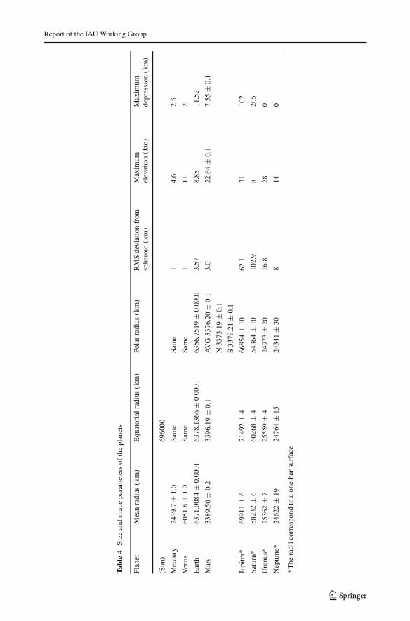
Table 4 gives the size and shape parameters for the planets. The Sun is included for com-parison purposes. Average (AVG), north (N), and south (S) polar radii are given for Mars.For the purpose of adopting a best-fitting ellipsoid for Mars, the average polar radius shouldbe used—the other values are for comparison only, e.g. to illustrate the large dichotomy inshape between the northern and southern hemispheres of Mars. In applications where thesedifferences may cause problems, the earlier recommended topographic shape model for Marsshould probably be used as a reference surface. The mean radii shown in Tables 4, 5, and 6 ingeneral (the Earth is an exception) are from the original authors and have not been computed
123
B. A. Archinal et al.
from the other radii by the Working Group on the assumption that at least some of them areindependently computed.
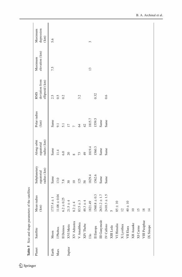
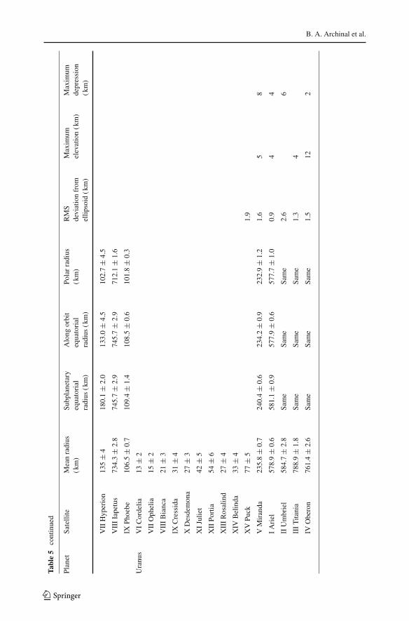
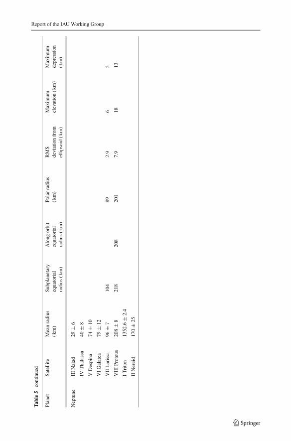
Table 5 gives the size and shape of satellites where known. Only brightnesses are knownfor many of the newly discovered satellites. Poles and rotation rates are also not yet known forthe new discoveries, so those satellites are not listed. A mean radius and best fitting triaxialradii are given for Titan. The triaxial radii are for comparison only, as the differences aresmall enough that the mean radius should be used for most cartographic purposes.
The values of the radii and axes in Tables 4 and 5 are derived by various methods and donot always refer to common definitions. Some use star or spacecraft occultation measure-ments, some use limb fitting, others use altimetry measurements from orbiting spacecraft,and some use control network computations. For the Earth, the spheroid refers to mean sealevel, clearly a very different definition from other bodies in the Solar System.
The uncertainties in the values for the radii and axes in Tables 4 and 5 are generally thoseof the authors, and, as such, frequently have different meanings. Sometimes they are standarderrors of a particular data set, sometimes simply an estimate or expression of confidence.The radii and axes of the large gaseous planets, Jupiter, Saturn, Uranus, and Neptune inTable 4 refer to a one-bar-pressure surface. The radii given in the tables are not necessarilythe appropriate values to be used in dynamical studies; the radius actually used to derive avalue of J2 (for example) should always be used in conjunction with it. In Table 5, ellipsoidalfit axes of objects less than 200 km in radius are for convenient comparison and their use forany modeling can only be approximate.
7 Cartographic coordinates for dwarf planets, minor planets, their satellites,and comets
For large bodies, a spherical or ellipsoidal model shape has traditionally been defined formapping, as in our past reports. For irregularly shaped bodies the ellipsoid is obviouslyuseless, except perhaps for dynamical studies. For very irregular bodies, the concept of a ref-erence ellipsoid ceases to be useful for most purposes. For these bodies, topographic shapesare usually represented by a grid of radii to the surface as a function of planetocentric latitudeand longitude (when possible, or also by a set of vertices and polygons).
Another problem with smaller bodies is that two coordinates (i.e. spherical angular mea-sures) may not uniquely identify a point on the surface of the body. In other words it ispossible to have a line from the center of the object intersect the surface more than once.This can happen on large and even mostly ellipsoidal objects such as the Earth, because ofsuch features as overhanging cliffs and natural bridges and arches. However, on large bodiesthese features are relatively very small and often ignored at the scale of most topographicmaps. For small bodies they may be fairly large relative to the size of the body. Examplecases are on Eros (at a small patch west of Psyche), and certainly on Kleopatra (Ostro et al.2000), possibly on Toutatis near its ‘neck,’ and perhaps near the south pole of Ida, someradii may intersect the surface more than once. Even on small bodies this problem is usuallyrestricted to small areas, but it still may make a planetocentric coordinate system difficultto use. Cartographers always have ad hoc tricks for a specific map, such as interpolatingacross the problem area from areas which are uniquely defined, or by showing overlappingcontours. A Cartesian or other coordinate geometry may be preferable for arbitrarily complexshapes, such as a toroidal comet nucleus, where an active region has eaten its way throughthe nucleus. Such coordinate geometries may also be useful for irregular bodies imaged onlyon one side, such as for 19P/Borrelly and 81P/Wild 2.
123
Report of the IAU Working Group
Tabl
e4
Size
and
shap
epa
ram
eter
sof
the
plan
ets
Plan
etM
ean
radi
us(k
m)
Equ
ator
ialr
adiu
s(k
m)
Pola
rra
dius
(km
)R
MS
devi
atio
nfr
omsp
hero
id(k
m)
Max
imum
elev
atio
n(k
m)
Max
imum
depr
essi
on(k
m)
(Sun
)69
6000
Mer
cury
2439
.7±
1.0
Sam
eSa
me
14.
62.
5
Ven
us60
51.8
±1.
0Sa
me
Sam
e1
112
Ear
th63
71.0
084
±0.
0001
6378
.136
6±
0.00
0163
56.7
519
±0.
0001
3.57
8.85
11.5
2
Mar
s33
89.5
0±
0.2
3396
.19
±0.
1A
VG
3376
.20
±0.
13.
022
.64
±0.
17.
55±
0.1
N33
73.1
9±
0.1
S33
79.2
1±
0.1
Jupi
ter*
6991
1±
671
492
±4
6685
4±
1062
.131
102
Satu
rn*
5823
2±
660
268
±4
5436
4±
1010
2.9
820
5
Ura
nus*
2536
2±
725
559
±4
2497
3±
2016
.828
0
Nep
tune
*24
622
±19
2476
4±
1524
341
±30
814
0
*T
hera
diic
orre
spon
dto
aon
e-ba
rsu
rfac
e
123
B. A. Archinal et al.
Tabl
e5
Size
and
shap
epa
ram
eter
sof
the
sate
llite
s
Plan
etSa
telli
teM
ean
radi
us(k
m)
Subp
lane
tary
equa
tori
alra
dius
(km
)
Alo
ngor
bit
equa
tori
alra
dius
(km
)
Pola
rra
dius
(km
)R
MS
devi
atio
nfr
omel
lipso
id(k
m)
Max
imum
elev
atio
n(k
m)
Max
imum
depr
essi
on(k
m)
Ear
thM
oon
1737
.4±
1Sa
me
Sam
eSa
me
2.5
7.5
5.6
Mar
sI
Phob
os11
.08
±0.
0413
.011
.49.
10.
5
IID
eim
os6.
2±
0.25
7.8
6.0
5.1
0.2
Jupi
ter
XV
IM
etis
21.5
±4
3020
17
XV
Adr
aste
a8.
2±
410
87
VA
mal
thea
83.5
±3
125
7364
3.2
XIV
The
be49
.3±
458
4942
IIo
1821
.49
1829
.418
19.4
1815
.713
3
IIE
urop
a15
60.8
±0.
315
62.6
1560
.315
59.5
0.32
III
Gan
ymed
e26
31.2
±1.
7Sa
me
Sam
eSa
me
IVC
allis
to24
10.3
±1.
5Sa
me
Sam
eSa
me
0.6
XII
IL
eda
5
VI
Him
alia
85±
10
XLy
sith
ea12
VII
Ela
ra40
±10
XII
Ana
nke
10
XI
Car
me
15
VII
IPa
siph
ae18
IXSi
nope
14
123

Report of the IAU Working Group
Tabl
e5
cont
inue
d
Plan
etSa
telli
teM
ean
radi
us(k
m)
Subp
lane
tary
equa
tori
alra
dius
(km
)
Alo
ngor
bit
equa
tori
alra
dius
(km
)
Pola
rra
dius
(km
)R
MS
devi
atio
nfr
omel
lipso
id(k
m)
Max
imum
elev
atio
n(k
m)
Max
imum
depr
essi
on(k
m)
Satu
rnX
VII
IPa
n14
.1±
1.3
17.2
±1.
915
.7±
1.3
10.4
±0.
84
XX
XV
Dap
hnis
3.8
±0.
84.
3±
0.7
4.1
±0.
93.
2±
0.8
XV
Atla
s15
.1±
0.9
20.4
±1.
217
.7±
0.7
9.4
±0.
8
XV
IPr
omet
heus
43.1
±2.
767
.8±
3.1
39.7
±3.
129
.7±
1.9
XV
IIPa
ndor
a40
.7±
1.5
52.0
±1.
840
.5±
2.0
32.0
±0.
9
XI
Epi
met
heus
58.1
±1.
864
.9±
2.0
57.0
±3.
753
.1±
0.7
XJa
nus
89.5
±1.
410
1.5
±1.
992
.5±
1.2
76.3
±1.
2
IM
imas
198.
2±
0.4
207.
8±
0.5
196.
7±
0.5
190.
6±
0.3
XX
XII
Met
hone
1.6
±0.
6Sa
me
Sam
eSa
me
XL
IXA
nthe
∼1X
XX
III
Palle
ne2.
5±
0.6
2.9
±0.
62.
8±
0.8
2.0
±0.
4
IIE
ncel
adus
252.
1±
0.2
256.
6±
0.6
251.
4±
0.2
248.
3±
0.2
0.4
III
Teth
ys53
1.0
±0.
653
8.4
±0.
352
8.3
±1.
152
6.3
±0.
6
XII
ITe
lest
o12
.4±
0.4
16.3
±0.
511
.8±
0.3
10.0
±0.
3
XIV
Cal
ypso
10.7
±0.
715
.1±
0.3
11.5
±2.
27.
0±
0.6
IVD
ione
561.
4±
0.4
563.
4±
0.6
561.
3±
0.5
559.
6±
0.4
0.5
XII
Hel
ene
17.6
±0.
421
.7±
0.5
19.1
±0.
313
.0±
0.3
XX
XIV
Poly
deuc
es1.
3±
0.4
1.5
±0.
61.
2±
0.4
1.0
±0.
2
VR
hea
763.
5±
0.6
765.
0±
0.7
763.
1±
0.6
762.
4±
0.6
VI
Tita
n25
74.7
3±
0.09
2575
.15
±0.
0225
74.7
8±
0.06
2574
.47
±0.
060.
26
123
B. A. Archinal et al.
Tabl
e5
cont
inue
d
Plan
etSa
telli
teM
ean
radi
us(k
m)
Subp
lane
tary
equa
tori
alra
dius
(km
)
Alo
ngor
bit
equa
tori
alra
dius
(km
)
Pola
rra
dius
(km
)R
MS
devi
atio
nfr
omel
lipso
id(k
m)
Max
imum
elev
atio
n(k
m)
Max
imum
depr
essi
on(k
m)
VII
Hyp
erio
n13
5±
418
0.1
±2.
013
3.0
±4.
510
2.7
±4.
5
VII
IIa
petu
s73
4.3
±2.
874
5.7
±2.
974
5.7
±2.
971
2.1
±1.
6
IXPh
oebe
106.
5±
0.7
109.
4±
1.4
108.
5±
0.6
101.
8±
0.3
Ura
nus
VI
Cor
delia
13±
2
VII
Oph
elia
15±
2
VII
IB
ianc
a21
±3
IXC
ress
ida
31±
4
XD
esde
mon
a27
±3
XI
Julie
t42
±5
XII
Port
ia54
±6
XII
IR
osal
ind
27±
4
XIV
Bel
inda
33±
4
XV
Puck
77±
51.
9
VM
iran
da23
5.8
±0.
724
0.4
±0.
623
4.2
±0.
923
2.9
±1.
21.
65
8
IA
riel
578.
9±
0.6
581.
1±
0.9
577.
9±
0.6
577.
7±
1.0
0.9
44
IIU
mbr
iel
584.
7±
2.8
Sam
eSa
me
Sam
e2.
66
III
Tita
nia
788.
9±
1.8
Sam
eSa
me
Sam
e1.
34
IVO
bero
n76
1.4
±2.
6Sa
me
Sam
eSa
me
1.5
122
123
Report of the IAU Working Group
Tabl
e5
cont
inue
d
Plan
etSa
telli
teM
ean
radi
us(k
m)
Subp
lane
tary
equa
tori
alra
dius
(km
)
Alo
ngor
bit
equa
tori
alra
dius
(km
)
Pola
rra
dius
(km
)R
MS
devi
atio
nfr
omel
lipso
id(k
m)
Max
imum
elev
atio
n(k
m)
Max
imum
depr
essi
on(k
m)
Nep
tune
III
Nai
ad29
±6
IVT
hala
ssa
40±
8
VD
espi
na74
±10
VI
Gal
atea
79±
12
VII
Lar
issa
96±
710
489
2.9
65
VII
IPr
oteu
s20
8±
821
820
820
17.
918
13
IT
rito
n13
52.6
±2.
4
IIN
erei
d17
0±
25
123
B. A. Archinal et al.
With the introduction of large mass storage to computer systems, digital cartographyhas become increasingly popular. Cartographic databases are important when consideringirregularly shaped bodies and other bodies, where the surface can be described by a file con-taining the coordinates for each pixel. In this case the reference sphere has shrunk to a unitsphere. Other parameters such as brightness, gravity, etc., if known, can be associated witheach pixel. With proper programming, pictorial and projected views of the body can then bedisplayed.
Taking all of this into account, our recommendation is that longitudes on dwarf plan-ets, minor planets, their satellites, and comets should be measured positively from 0 to 360degrees using a right-hand system from a designated prime meridian. The origin is the centerof mass, to the extent known.
Latitude is measured positive and negative from the equator; latitudes toward the positivepole are designated as positive. For regular shaped bodies the cartographic latitude of apoint on the reference surface is the angle between the equatorial plane and the normal tothe reference surface at the point. In the cartographic system, the position of a point (P )not on the reference surface is specified by the cartographic latitude of the point (P ′) onthe reference surface at which the normal passes through P and by the height (h) of Pabove P ′.
For irregular bodies orthographic digital projections often are adopted for cartographicportrayal as these preserve the irregular appearance of the body without artificial distortion.These projections should also follow the right-hand rule.
Table 6 contains data on the size and shape of selected dwarf planets, minor planets, theirsatellites, and comets. The first column gives the effective radius of the body and an estimateof the accuracy of this measurement. This effective radius is for a sphere of equivalent vol-ume. The next three columns give estimates of the radii measured along the three principalaxes.
The uncertainties in the values for the radii in Table 6 are generally those given by theauthors, and, as such, frequently have different meanings. Sometimes they are standard errorsof a particular data set, sometimes simply an estimate or expression of confidence.
A dwarf planet, minor planet, one of their satellites, or a comet will typically be includedin Table 6 only if it meets fundamental publication, data quality, and applicability criteria.Estimated values for the body’s size and shape (modeled as a spheroid) should have beenpublished in a refereed journal (or a revision that is in preparation). The analysis to determinethese values will have been derived from data of sufficient fidelity and quality to assure anaccurate estimate, and some portion of that data will have been acquired via direct methods(e.g. direct imaging from a spacecraft, a space telescope, or an adaptive optics system). Lastly,a cartographic need must exist that justifies the definition of a size and shape for this body.
The radii given in the tables are not necessarily the appropriate values to be used in dynam-ical studies; the radius actually used to derive a value for the dynamical form factor (J2) (forexample) should always be used in conjunction with it.
8 Recommendations
Although we have not done so in the past, the Working Group briefly summarizes herewhat we have come to see as current urgent needs relative to the development of planetarycartographic products.
123
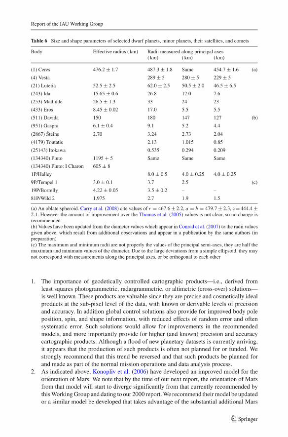
Report of the IAU Working Group
Table 6 Size and shape parameters of selected dwarf planets, minor planets, their satellites, and comets
Body Effective radius ( km) Radii measured along principal axes( km) ( km) ( km)
(1) Ceres 476.2 ± 1.7 487.3 ± 1.8 Same 454.7 ± 1.6 (a)
(4) Vesta 289 ± 5 280 ± 5 229 ± 5
(21) Lutetia 52.5 ± 2.5 62.0 ± 2.5 50.5 ± 2.0 46.5 ± 6.5
(243) Ida 15.65 ± 0.6 26.8 12.0 7.6
(253) Mathilde 26.5 ± 1.3 33 24 23
(433) Eros 8.45 ± 0.02 17.0 5.5 5.5
(511) Davida 150 180 147 127 (b)
(951) Gaspra 6.1 ± 0.4 9.1 5.2 4.4
(2867) Šteins 2.70 3.24 2.73 2.04
(4179) Toutatis 2.13 1.015 0.85
(25143) Itokawa 0.535 0.294 0.209
(134340) Pluto 1195 + 5 Same Same Same
(134340) Pluto: I Charon 605 ± 8
1P/Halley 8.0 ± 0.5 4.0 ± 0.25 4.0 ± 0.25
9P/Tempel 1 3.0 ± 0.1 3.7 2.5 (c)
19P/Borrelly 4.22 ± 0.05 3.5 ± 0.2 – –
81P/Wild 2 1.975 2.7 1.9 1.5
(a) An oblate spheroid. Carry et al. (2008) cite values of r = 467.6 ± 2.2, a = b = 479.7 ± 2.3, c = 444.4 ±2.1. However the amount of improvement over the Thomas et al. (2005) values is not clear, so no change isrecommended(b) Values have been updated from the diameter values which appear in Conrad et al. (2007) to the radii valuesgiven above, which result from additional observations and appear in a publication by the same authors (inpreparation)(c) The maximum and minimum radii are not properly the values of the principal semi-axes, they are half themaximum and minimum values of the diameter. Due to the large deviations from a simple ellipsoid, they maynot correspond with measurements along the principal axes, or be orthogonal to each other
1. The importance of geodetically controlled cartographic products—i.e., derived fromleast squares photogrammetric, radargrammetric, or altimetric (cross-over) solutions—is well known. These products are valuable since they are precise and cosmetically idealproducts at the sub-pixel level of the data, with known or derivable levels of precisionand accuracy. In addition global control solutions also provide for improved body poleposition, spin, and shape information, with reduced effects of random error and oftensystematic error. Such solutions would allow for improvements in the recommendedmodels, and more importantly provide for higher (and known) precision and accuracycartographic products. Although a flood of new planetary datasets is currently arriving,it appears that the production of such products is often not planned for or funded. Westrongly recommend that this trend be reversed and that such products be planned forand made as part of the normal mission operations and data analysis process.
2. As indicated above, Konopliv et al. (2006) have developed an improved model for theorientation of Mars. We note that by the time of our next report, the orientation of Marsfrom that model will start to diverge significantly from that currently recommended bythis Working Group and dating to our 2000 report. We recommend their model be updatedor a similar model be developed that takes advantage of the substantial additional Mars
123
B. A. Archinal et al.
data available since the time of their work, so that it can be adopted by this WorkingGroup and operational Mars missions in the 2012 time frame.
3. As described above, there appear to be a number of slightly conflicting determinationsfor the rotation rates of Jupiter and Saturn. We urge the planetary community to jointlyaddress resolving the various determinations and to develop consensus determinations,such as was done in the past for Jupiter by Riddle and Warwick (1976).
Acknowledgments We appreciate useful input from J. Blue, B. Carry, T. Duxbury, K. Edmundson,C. Higgins, C. Hohenkerk, L. Jorda, R. Kirk, Y. Li, J.-L. Margot, D. McCarthy, T. Roatsch, C. Russell,L. Spilker, and J. Williams.
Appendix: changes since the last report
This appendix summarizes the changes that have been made since the 2006 report (CelestialMechanics and Dynamical Astronomy 98, 155–180, 2007).
1. Following the list of dwarf planets defined by the IAU WGPSN and the CSBN (2010),the entries for Pluto and Charon have been moved to Tables 3 and 6 and adapted to thepositive pole definition, and the entry for Ceres moved to Table 6.
2. A new pole and rotation model has been implemented for Mercury, based on the deter-mination of Margot 2009, but using the previous value of W0. See Sect. 4 for furtherdetails.
3. An algorithm is described in the text for expressing the orientation of the Moon usingthe JPL DE 421 lunar ephemeris, rotated to the mean Earth/polar axis system, in orderto obtain the pole and rotation with high precision.
4. The new pole and rotation model of Konopliv et al. (2006) for Mars continues to benoted in the text, but is not recommended for general use at this time.
5. The rotation rate of Jupiter was updated in the 2000 report (Seidelmann et al. 2002)based on a new determination by Higgins et al. (1997). That rate is different fromthe previously accepted value (“System III (1965)”) of Riddle and Warwick (1976)and is not in agreement with new determinations by Russell et al. (2001) and Yu andRussell (2009). After discussion with some of these authors (Higgins 2010, privatecommunication; Russell 2010, private communication), here it is changed back to theprevious Riddle and Warwick (1976) value. Higgins, Russell, and the Working Grouprecommend that a community consensus on a new value be achieved—much as wasfacilitated by Riddle and Warwick—before a new value is adopted.
6. Several proposed new rotation models for Saturn are noted in the text, but not recom-mended for general use at this time. As with Jupiter, the Working Group recommendsthat a community consensus on a new model be achieved before a new value is adopted.
7. The rotation models of Mimas, Enceladus, Tethys, Dione, and Iapetus have beenupdated in Table 2 based on the Table 24.4 values in Roatsch et al. (2009a). (TheDione model is originally from Roatsch et al. (2008b); the Mimas, Tethys, and Iapetusmodels are originally from Roatsch et al. (2009b); the revised Enceladus model was notyet derived when Roatsch et al. (2008a) was published.). These changes are to the valuesofW0 for these bodies, based on semi-controlled (including limb fitting) new mappingof these bodies. Note that in some further interim revisions of the relevant mappingproducts, W0 has not been further updated, resulting in some variation in longitude ofthe defining features in the interim products. Final products will be made later withassociated further updates to the W0 values (Roatsch 2009, private communication).
123
Report of the IAU Working Group
The rotation model of Titan has been updated in Table 2 based on the improved poleposition and synchronous spin model of Stiles et al. (2008) and as formulated in CassiniProject (2009). This model was derived from Cassini RADAR observations of Titan.A model for nonsynchronous spin, resulting from surface-atmosphere interactions andpossibly indicating, by its magnitude, the presence of a sub-surface ocean (Lorenz et al.2008), is as yet not sufficiently definitive to be adopted. Note that the adopted modeldoes not include any terms for precession and nutation, but for pole position fits thedata better than the previous WG model that assumed a pole perpendicular to the orbitalplane. Stiles et al. (2010) note a correction to their earlier work, substantially reducingthe inferred nonsynchronous rotation rate and giving a slightly different pole position,but they do not provide a compatible spin model, so the newer determination is notadopted here.
8. Clarification has been added to Sect. VI to explain when positive longitudes are east orwest in the planetocentric and planetographic coordinate systems.
9. (1) Ceres has been added to Table 3 based on work described by Thomas et al. (2005),Li et al. (2006a), and Li et al. (2006b). W0 has been derived from W = 333.14◦ at theUTC epoch 2003-12-28T10:51:59 (Thomas 2010, private communication). The periodof 9.074170 hours from Chamberlain et al. (2007) has been used to derive the rotationrate. (2) Pallas, (21) Lutetia, (511) Davida, and (2867) Šteins have been added to Table 3from Carry et al. (2010a) (Pallas); Carry et al. (2010b) (Lutetia), Conrad et al. (2007)(Davida); and Jorda et al. (2010) and Keller et al. (2010) (Šteins). Schmidt et al. (2009)have determined a pole position for (2) Pallas of α0 = 42◦ ± 10 and δ0 = −12◦ ± 10.However, since they provide no corresponding information on spin, values for the poleposition and spin from Carry et al. (2010a) have been recommended here. The poleposition for (4) Vesta has been updated from Li et al. (2010).
10. The equatorial radius of the Sun has been added to Table 4 for comparison, as speci-fied in the IAU (1976) System of Astronomical Constants (International AstronomicalUnion (IAU) 1977, pp. 31, 52–66).
11. The size and shape of the Earth has been updated based on International Associationof Geodesy recommendations (Groten 2000). The (zero frequency tide) mean equato-rial radius, a, is used as is (ibid., equation 46), while the (zero frequency tide) meanpolar flattening, 1/f (ibid., equation 22), is used to calculate the mean polar radius,b = a− af . The mean radius is calculated via the arithmetic mean (2a+ b)/3 (Moritz1980, 392). The RMS deviation from the spheroid, the maximum elevation, and max-imum depression has been left at their previous values since they are only intended tobe approximate. The a and 1/f values used are also those recommended in the IERSConventions (McCarthy and Petit 2004).
12. Sizes and shapes have been updated in Table 5 for Phobos and Deimos based on Willneret al. (2010) and Thomas (1993) respectively.
13. Sizes and shapes have been updated in Table 5 for the Galilean satellites of Jupiter basedon Thomas et al. (1998) (Io); Anderson et al. (2001a) (Ganymede), Anderson et al.(2001b) (Callisto), and Nimmo et al. (2007) (Europa). While making these updates, wehave noted that the previous recommended sizes and shapes for the Galilean satellitesdo not originate from Davies et al. (1998) as indicated in the 2000 report (Seidelmannet al. 2002) but rather from the Galileo SSI instrument team (K. P. Klassen, e-mail of2000 November 13). The mean radii for Europa, Ganymede, and Callisto there camefrom M. Davies and T. Colvin via photogrammetric solutions and the mean radius forIo and the triaxial radii for all four satellites came from P. Thomas via limb fit solutions.
123
B. A. Archinal et al.
14. Sizes and shapes have been updated in or added to Table 5 for the Saturnian satellites(in order outward from Saturn) Pan, Daphnis, Atlas, Prometheus, Pandora, Epimetheus,Janus, Mimas, Methone, Pallene, Tethys, Telesto, Calypso, Dione, Helene, Polydeuces,Rhea, Hyperion, Iapetus, and Phoebe, based on new determinations listed by Thomas(2010); and for Anthe based on a new determination listed by Porco et al. (2007). Sizeand shape information for Titan is updated from Zebker et al. (2009). Also note that inthe 2006 report (Seidelmann et al. 2007, pp. 174–175) the along orbit equatorial radiusof Metis should have been listed as 20 km, the polar radius as 17 km, and the RMSdeviation from the ellipsoid as blank; and the mean radius of Helene should have beenlisted as 16 km and the RMS deviation from the ellipsoid as 0.7 km.
15. In Table 6 a mean radius value from Thomas et al. (2005) has been added for (1) Ceresand a footnote added to note an alternate determination of Ceres’ shape by Carry et al.(2008). Clarifying what was shown in the 2006 report (Seidelmann et al. 2007, p. 177)since it is an oblate spheroid, the first and second axes are listed as being the same,different from the third axis. (21) Lutetia, (511) Davida and (2867) Šteins have beenadded to Table 6 from Drummond et al. (2010) (Lutetia), Conrad et al. (2007) (Dav-ida), and Jorda et al. (2010) and Keller et al. (2010) (Šteins). Schmidt et al. (2009) andCarry et al. (2010a) have both determined shape parameters for (2) Pallas. These arerespectively: r = 272, a = 291 ± 9, b = 278 ± 9, and c = 250 ± 9; r = 256 ± 3, a = 275± 4, b = 258 ± 3, and c = 238 ± 3 km. We have been unable to clearly differentiatewhich is superior so make no recommendation as to which to use at this time.
References
Anderson, J.D., Schubert, G.: Saturn’s gravitational field, internal rotation, and interior structure.Science 317, 1384–1387 (2007). doi:10.1126/science.1144835
Anderson, J.D., Jacobson, R.A., Lau, E.L., Moore, W.B., Olsen, O., Schubert, G., Thomas, P.C.: GalileoGravity Science Team: Shape, Mean Radius, Gravity Field and Interior Structure of Ganymede. DPSMeeting #33. Bull. Am. Astron. Soc. 33, 1101 (2001)
Anderson, J.D., Jacobson, R.A., McElrath, T.P., Moore, W.B., Schubert, G., Thomas, P.C.: Shape, mean radius,gravity field, and interior structure of callisto. Icarus 153, 157–161 (2001)
Carry, B., Dumas, C., Fulchignoni, M., Merline, W.J., Berthier, J., Hestroffer, D., Fusco, T., Tamblyn, P.:Near-infrared mapping and physical properties of the dwarf-planet Ceres. Astron. Astroph. 478, 235–244 (2008). doi:10.1051/0004-6361:20078166
Carry, B., Dumas, C., Kaasalainen, M., Berthier, J., Merline, W.J., Erard, S., Conrad, A., Drummond, J.D.,Hestroffer, D., Fulchignoni, M., Fusco, T.: Physical properties of (2) Pallas. Icarus 205, 460–472 (2010).doi:10.1016/j.icarus.2009.08.007
Carry, B., Kaasalainen, M., Leyrat, C., Merline, W.J., Drummond, J.D., Conrad, A., Weaver, H.A., Tamblyn,P.M., Chapman, C.R., Dumas, C., Colas, F., Christou, J.C., Dotto, E., Perna, D., Fornasier, S., Bernas-coni, L., Behrend, R., Vachier, F., Kryszczynska, A., Polinska, M., Fulchignoni, M., Roy, R., Naves, R.,Poncy, R., Wiggins, P.: Physical properties of ESA Rosetta target asteroid (21) Lutetia: shape and flybygeometry. Astron. & Astroph. (2010, in press). doi:10.1051/0004-6361/201015074
Cassini Project: Planetary Constants (PcK) SPICE kernel. May 7 (2009), ftp://naif.jpl.nasa.gov/pub/naif/CASSINI/kernels/pck/cpck07May2009.tpc. Accessed 2010 October 18
Chamberlain, M.A., Sykes, M.V., Esquerdo, G.A.: Ceres lightcurve analysis—period determination.Icarus 188, 451–456 (2007)
Conrad, A.R., Dumas, C., Merline, W.J., Drummond, J.D., Campbell, R.D., Goodrich, R.W., Le Mignant, D.,Chaffee, F.H., Fusco, T., Kwok, S.H., Knight, R.I.: Direct measurement of 511 the size, shape, and poleof Davida with Keck AO in a single night. Icarus 191, 616–627 (2007). doi:10.1016/j.icarus.2007.05.004
Davies, M.E., Abalakin, V.K., Cross, C.A., Duncombe, R.L., Masursky, H., Morando, B., Owen, T.C., Seidel-mann, P.K., Sinclair, A.T., Wilkins, G.A., Tjuflin, Y.S.: Report of the IAU Working Group on CartographicCoordinates and Rotational Elements of the Planets and Satellites. Celest. Mech. 22, 205–230 (1980)
123
Report of the IAU Working Group
Davies, M.E., Abalakin, V.K., Lieske, J.H., Seidelmann, P.K., Sinclair, A.T., Sinzi, A.M., Smith, B.A., Tjuflin,Y.S.: Report of the IAU working group on cartographic coordinates and rotational elements of the planetsand satellites: 1982. Celest. Mech. 29, 309–321 (1983)
Davies, M.E., Abalakin, V.K., Bursa, M., Lederle, T., Lieske, J.H., Rapp, R.H., Seidelmann, P.K., Sinclair, A.T.,Teifel, V.G., Tjuflin, Y.S.: Report of the IAU/IAG COSPAR working group on cartographic coordinatesand rotational elements of the planets and satellites: 1985. Celest. Mech. 39, 103–113 (1986)
Davies, M.E., Abalakin, V.K., Bursa, M., Hunt, G.E., Lieske, J.H., Morando, B., Rapp, R.H., Seidelmann, P.K.,Sinclair, A.T., Tjuflin, Y.S.: Report of the IAU/IAG/COSPAR working group on cartographic coordinatesand rotational elements of the planets and satellites: 1988. Celest. Mech. Dyn. Astron. 46, 187–204 (1989)
Davies, M.E., Abalakin, V.K., Brahic, A., Bursa, M., Chovitz, B.H., Lieske, J.H., Seidelmann, P.K., Sinclair,A.T., Tjuflin, Y.S.: Report of the IAU/IAG/COSPAR working group on cartographic coordinates androtational elements of the planets and satellites: 1991. Celest. Mech. Dyn. Astron. 53, 377–397 (1992)
Davies, M.E., Abalakin, V.K., Bursa, M., Lieske, J.H., Morando, B., Seidelmann, P.K., Sinclair, A.T.,Yallop, B., Tjuflin, Y.S.: Report of the IAU/IAG/COSPAR working group on cartographic coordinatesand rotational elements of the planets and satellites: 1994. Celest. Mech. Dyn. Astron. 63, 127–148 (1996)
Davies, M.E., Colvin, T.R., Oberst, J., Zeitler, W., Schuster, P., Neukum, G., McEwen, A.S., Phillips, C.B.,Thomas, P.C., Veverka, J., Belton, M.J.S., Schubert, G.: The control networks of the Galilean satellitesand implications for global shape. Icarus 135, 372–376 (1998). doi:10.1006/icar.1998.5982
Davies, M.E., Colvin, T.R.: Lunar coordinates in the regions of the Apollo landers. JGR 105(E8), 20,277–20,280 (2000)
de Vaucouleurs, G., Davies, M.E., Sturms, F.M Jr..: Mariner 9 areographic coordinate system. JGR 78, 4395–4404 (1973)
Drummond, J.D., Conrad, A., Merline, W.J., Carry, B., Chapman, C.R., Weaver, H.A., Tamblyn, P.M., Christou,J.C., Dumas, C.: The triaxial ellipsoid dimensions, rotational pole, and bulk density of ESA Rosetta targetasteroid (21) Lutetia. Astron. & Astroph. (2010, in press). doi:10.1051/0004-6361/201015075
Duxbury, T.: Minutes of 2006 October 3 Meeting of the MGCWG, as of 2006 October 31 (2006)Folkner, W.M., Williams, J.G., Boggs, D.H.: The Planetary and Lunar Ephemeris DE 421. JPL Memorandum
IOM 343R-08-003, 31 March (2008). Available as ftp://ssd.jpl.nasa.gov/pub/eph/planets/ioms/de421.iom.v1.pdf. Accessed 2010 October 18
Folkner, W.M., Williams, J.G., Boggs, D.H.: The Planetary and Lunar Ephemeris DE 421. IPN ProgressReport 42-178, August 15 (2009). Available as http://ipnpr.jpl.nasa.gov/progress_report/42-178/178C.pdf. Accessed 2010 October 18
Giampieri, G., Dougherty, M.K., Smith, E.J., Russell, C.T.: A regular period for Saturn’s magnetic field thatmay track its internal rotation. Nature 441, 62–64 (2006)
Groten, E.: Report of Special Commission 3 of IAG. In: Johnston, K. J, et al. (eds.) Toward Modelsand Constants for Sub-Microarcsecond Astrometry, U.S. Naval Observatory, Washington, D.C., pp.337–352 (2000). Available as http://www.dtic.mil/cgi-bin/GetTRDoc?Location=U2&doc=GetTRDoc.pdf&AD=ADA435898. Accessed 2010 October 18
Gurnett, D.A., Persoon, A.M., Kurth, W.S., Groene, J.B., Averkamp, T.F., Dougherty, M.K., Southwood,D.J.: The variable rotation period of the inner region of Saturn’s plasma disk. Science 316, 442–445 1–16, April 20 (2007)
Higgins, C.A., Carr, T.D., Reyes, F., Greenman, W.B., Lebo, G.R.: A redefinition of Jupiter’s rotationperiod. JGR 102(A10), 22,033–22,041 (1997)
International Astronomical Union (IAU): Proceedings of the Sixteenth General Assembly. Transactionsof the IAU, XVI B, D. Reidel Publishing Company, Dordrecht (1977). A copy of the 1976 IAUResolutions including the “IAU (1976) System of Astronomical Constants” is available on-line ashttp://www.iau.org/static/resolutions/IAU1976_French.pdf. Accessed 2010 October 18
International Astronomical Union (IAU) Working Group for Planetary System Nomenclature (WGPSN)and International Astronomical Union Committee on Small Body Nomenclature: Dwarf Planets andtheir Systems (2010), http://planetarynames.wr.usgs.gov/append7.html#DwarfPlanets. Accessed 2010October 18
Jorda, L., Lamy, P., Groussin, O., Besse, S., Faury, G., Gaskell, R., Gesquière, G., Kaasalainen, M.: Aster-oid (2867) Steins: shape, topography and geology from OSIRIS observations, to be submitted to Icarus(2010)
Keller, H.U., Barbieri, C., Koschny, D., Lamy, P., Rickman, H., Rodrigo, R., Sierks, H., A’Hearn, M.F., Angr-illi, F., Barucci, M.A., Bertaux, J.-L., Cremonese, G., Da Deppo, V., Davidsson, B., De Cecco, M., Debei,S., Fornasier, S., Fulle, M., Groussin, O., Gutierrez, P.J., Hviid, S.F., Ip, W.-H., Jorda, L., Knollenberg,J., Kramm, J.R., Kührt, E., Küppers, M., Lara, L.-M., Lazzarin, M., Moreno, J.L., Marzari, F., Michalik,H., Naletto, G. Sabau, G. Thomas, G. Wenzel, G. Bertini, G. Besse, G. Ferri, G. Kaasalainen, G. Lowry,G. Marchi, G. Mottola, G. Sabolo, G. Schröder, G. Spjuth, G. Vernazza, G.: E-Type Asteroid (2867)
123
B. A. Archinal et al.
Steins as Imaged by OSIRIS on Board Rosetta. Science 327, 190–193 (2010). doi:10.1126/science.1179559
Konopliv, A.S., Asmar, S.W., Carranza, E., Sjogren, W.L., Yuan, D.-N.: Recent gravity models as a result ofthe Lunar Prospector mission. Icarus 150, 1–18 (2001)
Konopliv, A.S., Yoder, C.F., Standish, E.M., Yuan, D.-N., Sjogren, W.L.: A global solution for the Mars staticand seasonal gravity, Mars orientation, Phobos and Deimos masses, and Mars ephemeris. Icarus 182,23–50 (2006)
Kovalevsky, J., Seidelmann, P.K.: Fundamentals of Astrometry. Cambridge University Press,Cambridge (2004)
Kurth, W.S., Lecacheux, A., Averkamp, T.F., Groene, J.B., Gurnett, D.A.: A Saturnian longitude system basedon a variable kilometric radiation period. GRL 24, L02201 (2007). doi:10.1029/2006GL028336
Li, J.-Y., McFadden, L.A., Parker, J.W., Young, E.F., Stern, S.A., Thomas, P.C., Russell, C.T., Sykes, M.V.: Pho-tometric analysis of 1 Ceres and surface mapping from HST observations. Icarus 182, 143–160 (2006a).doi:10.1016/j.icarus.2005.12.012
Li, J.-Y., Young, E.F., Thomas, P.C., Parker, J.Wm., McFadden, L.A., Russell, C.T., Stern, S.A., Sykes, M.V.:HST Images, Albedo Maps, and Shape of 1 Ceres V1.0. EAR-A-HSTACS-5-CERESHST-V1.0. NASAPlanetary Data System (2006b). Available at http://sbn.psi.edu/pds/resource/cereshst.html. Accessed2010 October 18
Li, J.-Y., Thomas, P.C., Carcich, B., Mutchler, M.J., McFadden, L.A., Russell, C.T., Weinstein-Weiss, S.S.,Rayman, M.D., Raymond, C.A.: Improved Measurement of Asteroid (4) Vesta’s Rotational Axis Orien-tation. Icarus. (2010, in press). doi:10.1016/j.icarus.2010.09.019
Lorenz, R.D., Stiles, B.W., Kirk, R.L., Allison, M.D., Persidel Marmo, P., Iess, L., Lunine, J.I., Ostro, S.J.,Hensley, S.: Titan’s rotation reveals an internal Ocean and changing zonal winds. Science 319, 1649–1651 (2008). doi:10.1126/science.1151639
LRO Project and LGCWG (2008). A Standardized Lunar Coordinate System for the Lunar Reconnais-sance Orbiter and Lunar Datasets, Version 5, October 1. Available at http://lunar.gsfc.nasa.gov/library/LunCoordWhitePaper-10-08.pdf. Accessed 2010 October 18
Ma, C., Arias, E.F., Eubanks, T.M., Fey, A.L., Gontier, A.-M., Jacobs, C.S., Sovers, O.J., Archinal, B.A.,Charlot, P.: The international celestial reference frame as realized by very long baseline interferome-try. Astron. J. 116, 516–546 (1998)
Margot, J.-L.: A Mercury orientation model including non-zero obliquity and librations. Celest. Mech. Dyn.Astron. 105, 329–336 (2009). doi:10.1007/s10569-009-9234-1
McCarthy, D.D., Petit, G.: IERS Conventions (2003), IERS Technical Note no. 32, IERS ConventionsCentre, U.S. Naval Observatory and Bureau International des Poids et Mesures (2004). Availableon-line from http://www.iers.org/IERS/EN/DataProducts/Conventions/conventions.html?__nnn=true.Accessed 2010 October 18
Miller, J.K., Konopliv, A.S., Antreasian, P.G., Bordi, J.J., Chesley, S., Helfrich, C.E., Owen, W.M., Wang,T.C., Williams, B.G., Yeomans, D.K., Scheeres, D.J.: Determination of shape, gravity, and rotationalstate of asteroid 433 Eros. Icarus 155, 3–17 (2002)
Moritz, H.: Geodetic Reference System 1980. In: Tscherning, C.C. (ed.) The Geodesist’s Handbook 1984,Bulletin Géodésique, 58(3), pp. 388–398 (1980)
Nimmo, F., Thomas, P.C., Pappalardo, R.T., Moore, W.B.: The global shape of Europa: constraints on lateralshell thickness variations. Icarus 191, 183–192 (2007)
Ostro, S.J., Hudson, R.S., Nolan, M.C., Margot, J.-L., Scheeres, D.J., Campbell, D.B., Magri, C., Giosini,J.D., Yeomans, D.K.: Radar observations of asteroid 216 kleopatra. Science 288, 836–839 (2000)
Porco, C.C., Thomas, P.C., Weiss, J.W., Richardson, D.C.: Saturn’s small inner satellites: clues to their ori-gins. Science 318, 1602–1607 (2007). doi:10.1126/science.1143977
Riddle, A.C., Warwick, J.W.: Redefinition of system III longitude. Icarus 27, 457–459 (1976)Roatsch, T., Wählisch, M., Giese, B., Hoffmeister, A., Matz, K.-D., Scholten, F., Kuhn, A., Wagner, R.,
Neukum, G., Helfenstein, P., Porco, C.C.: High-resolution Enceladus atlas derived from Cassini-ISSimages. Planet. Space Sci. 56, 109–116 (2008)
Roatsch, T., Wählisch, M., Hoffmeister, A., Matz, K.-D., Scholten, F., Kersten, E., Wagner, R., Denk, T.,Neukum, G., Porco, C.C.: High-resolution Dione atlas derived from Cassini-ISS images. Planet. SpaceSci. 56, 1499–1505 (2008)
Roatsch, Th., Jaumann, R., Stephan, K., Thomas, P.C.: Cartographic mapping of the Icy satellites using ISSand VIMS data. In: Dougherty, et al. (eds.) Saturn from Cassini-Huygens. Springer, Berlin (2009a).doi:10.1007/978-1-4020-9215-2
Roatsch, Th., Wählisch, M., Hoffmeister, A., Kersten, E., Matz, K.-D., Scholten, F., Wagner, R., Denk, T.,Neukum, G., Helfenstein, P., Porco, C.: High-resolution Atlases of Mimas, Tethys, and Iapetus derivedfrom Cassini-ISS images. Planet. Space Sci. 57, 83–92 (2009b). doi:10.1016/j.pss.2008.10.014
123
Report of the IAU Working Group
Robinson, M.S., Davies, M.E., Colvin, T.R., Edwards, K.: A revised control network for Mercury.JGR 104(E12), 847–852 (1999)
Roncoli, R.: Lunar Constants and Models Document. JPL D-32296 (2005), available at http://ssd.jpl.nasa.gov/?lunar_doc. Accessed 2010 October 18
Russell, C.T., Yu, Z.J., Kivelson, M.G.: The Rotation Period of Jupiter. GRL 28(10), 1911–1912 (2001)Russell, C.T., Dougherty, M.K.: Magnetic Fields of the Outer Planets, SSR. January (2010). doi:10.1007/
s11214-009-9621-7Schmidt, B.E., Thomas, P.C., Bauer, J.M., Li, J.-Y., McFadden, L.A., Mutchler, M.J., Radcliffe, S.C., Rivkin,
A.S., Russell, C.T., Parker, J.Wm., Stern, S.A.: The shape and surface variation of 2 Pallas from theHubble Space Telescope. Science 326, 275–278 (2009). doi:10.1126/science.1177734
Seidelmann, P.K., Abalakin, V.K., Bursa, M., Davies, M.E., de Bergh, C., Lieske, J.H., Oberst, J., Simon,J.L., Standish, E.M., Stooke, P., Thomas, P.C.: Report of the IAU/IAG working group on cartographiccoordinates and rotational elements of the planets and satellites: 2000. Celest. Mech. Dyn. Astron. 82, 83–110 (2002)
Seidelmann, P.K., Archinal, B.A., A’Hearn, M.F., Cruiskshank, D.P., Hilton, J.L., Keller, H.U., Oberst, J.,Simon, J.L., Stooke, P., Tholen, D.J., Thomas, P.C.: Report on the IAU/IAG working group on carto-graphic coordinates and rotational elements: 2003. Celest. Mech. Dyn. Astron. 91, 203–215 (2005)
Seidelmann, P.K., Archinal, B.A., A’Hearn, M.F., Conrad, A., Consolmagno, G.J., Hestroffer, D., Hilton, J.L.,Krasinsky, G.A., Neumann, G., Oberst, J., Stooke, P., Tedesco, E., Tholen, D.J., Thomas, P.C., Wil-liams, I.P.: Report of the IAU/IAG working group on cartographic coordinates and rotational elements:2006. Celest. Mech. Dyn. Astron. 98, 155–180 (2007)
Smith, D., Neumann, B., Arvidson, R.E. Guinness, E.A., Slavney, S.: Mars global surveyor laser altime-ter mission experiment gridded data record. NASA Planetary Data System, MGS-M-MOLA-5-MEG-DR-L3-V1.0, 2003. Available on-line from http://pds-geosciences.wustl.edu/missions/mgs/megdr.html.Accessed 2010 October 18
Stevenson, D.J.: A new spin on Saturn. Nature 441, 35–344 (2006)Stiles, B.W., Kirk, R.L., Lorenz, R.D., Hensley, S., Lee, E., Ostro, S.J., Allison, M.D., Callahan, P.S., Gim,
Y., Iess, L., Percidel Marmo, P., Hamilton, G., Johnson, W.T.K., West, R.D.: The Cassini RADARTeam: Determining Titan’s spin state from Cassini RADAR images. Astron. J. 135, 1669–1680 (2008).doi:10.1088/0004-6256/135/5/1669
Stiles, B.W., Kirk, R.L., Lorenz, R.D., Hensley, S., Lee, E., Ostro, S.J., Allison, M.D., Callahan, P.S., Gim,Y., Iess, L., Percidel Marmo, P., Hamilton, G., Johnson, W.T.K., West, R.D.: The Cassini RADARTeam: ERRATUM: Determining Titan’s Spin State from Cassini RADAR Images. Astronomical Jour-nal 139, 311 (2010). doi:10.1088/0004-6256/139/1/311
Thomas, P.C.: Gravity, tides, and topography on small satellites and asteroids: Application to surface featuresof the martian satellites. Icarus 105, 326–344 (1993)
Thomas, P.C.: Sizes, shapes, and derived properties of the saturnian satellites after the Cassini nominal mis-sion. Icarus 208, 395–401 (2010). doi:10.1016/j.icarus.2010.01.025
Thomas, P.C., Davies, M.E., Colvin, T.R., Oberst, J., Schuster, P., Neukum, G., Carr, M.H., McEwen, A., Schu-bert, G., Belton, M.J.S.: The shape of Io from Galileo limb measurements. Icarus 135, 175–180 (1998)
Thomas, P.C., Parker, J.Wm., McFadden, L.A., Russell, C.T., Stern, S.A., Sykes, M.V., Young, E.F.: Differ-entiation of the asteroid Ceres as revealed by its shape. Nature 437, 224–226 (2005)
Thomas, P.C., Veverka, J., Belton, M.J.S., Hidy, A., A’Hearn, M.F., Farnham, T.L., Groussin, O., Li, J.-Y.,McFadden, L.A., Sunshine, J., Wellnitz, D., Lisse, C., Schultz, P., Meech, K.J., Delamere, W.A.: Theshape, topography, and geology of Tempel 1 from Deep Impact observations. Icarus 187, 4–15 (2007)
Thomas, P.C., Joseph, J., Carcich, B., Veverka, J., Clark, B.E., Bell, J.F., Byrd, A.W., Chomko, R., Robinson,M., Murchie, S., Prockter, L., Cheng, A., Izenberg, N., Malin, M., Chapman, C., McFadden, L.A., Kirk,R., Gaffey, M., Lucey, P.G.: Eros: shape, topography, and slope processes. Icarus 155, 18–37 (2002)
Williams, J.G., Boggs, D.H., Folkner, W.M.: DE421 Lunar Orbit, Physical Librations, and Surface Coordi-nates. JPL Interoffice Memorandum IOM 335-JW,DB,WF-20080314-001, 14 March (2008). Availableas ftp://ssd.jpl.nasa.gov/pub/eph/planets/ioms/de421_moon_coord_iom.pdf. Accessed 2010 October 18
Willner, K., Oberst, J., Hussmann, H., Giese, B., Hoffmann, H., Matz, K.-D., Roatsch, T., Duxbury, T.: Phoboscontrol point network, rotation, and shape. Earth Planet. Sci. Lett. 294, 541–546 (2010)
Yu, Z.J., Russell, C.T.: Rotation Period of Jupiter from the observation of its magnetic field.GRL 36, L20202 (2009). doi:10.1029/2009GL040094
Zebker, H.A., Stiles, B., Hensley, S., Lorenz, R., Kirk, R.L., Lunine, J.: Size and shape of Saturn’s moonTitan. Science 324, 921–923 (2009)
123