RCMS460 and RCMS490 Series - BENDER and RCMS490 Series ... Example system: ... Insulation...
10
RCMS460 and RCMS490 Series Digital Multi-Channel Ground Fault Monitor / Ground Fault Relay Grounded and High-Resistance Grounded AC/DC Systems T M 4 Technical Bulletin NAE1042060 / 04.2013
-
Upload
dangnguyet -
Category
Documents
-
view
239 -
download
3
Transcript of RCMS460 and RCMS490 Series - BENDER and RCMS490 Series ... Example system: ... Insulation...

RCMS460 and RCMS490 SeriesDigital Multi-Channel Ground Fault Monitor / Ground Fault Relay
Grounded and High-Resistance Grounded AC/DC Systems
T M
4
Technical BulletinNAE1042060 / 04.2013
2
RCMS460 / RCMS490 Series
RCMS460-D / -L and RCMS460-D / -L
Device features• Selectably monitor either pure AC, pure DC,
or AC/DC mix on each separate channel• True RMS value measurement • 12 separate monitoring channels, each with
its own settings adjustment• AC ground fault detection up to 2000 Hz• Fast parallel scanning for all channels• Response ranges
10 mA…10 A (DC or AC/DC mix) 6 mA…20 A (AC only systems)
• Latching or non-latching operation• Three separately adjustable time delays• Adjustable frequency behavior for
protec tion of persons, fire protection and plant protection
• History memory with date and time stamp for 300 data records
• Data logger for 300 data records / channel• Analysis of harmonics, DC, THD• Two Voltage-free SPDT contacts for
entire device• RCMS490: Additionally one voltage-free
SPST contact for each channel• Selectable between normally energized
and normally de energized operation• TEST / RESET button, internal / external• -D version: Digital backlit LCD display• Data exchange via BMS bus• Password protection• Continuous CT connection monitoring• Conforms to RoHS
Approvals
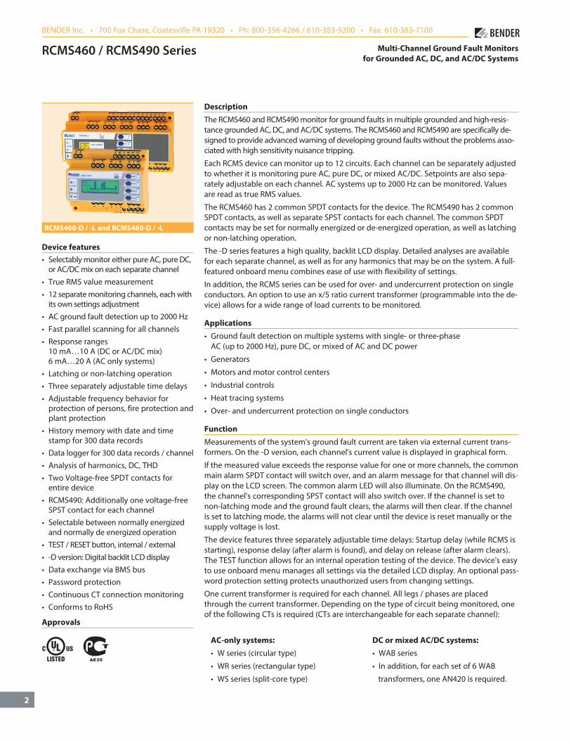
DescriptionThe RCMS460 and RCMS490 monitor for ground faults in multiple grounded and high-resis-tance grounded AC, DC, and AC/DC systems. The RCMS460 and RCMS490 are specifically de-signed to provide advanced warning of developing ground faults without the problems asso-ciated with high sensitivity nuisance tripping.
Each RCMS device can monitor up to 12 circuits. Each channel can be separately adjusted to whether it is monitoring pure AC, pure DC, or mixed AC/DC. Setpoints are also sepa-rately adjustable on each channel. AC systems up to 2000 Hz can be monitored. Values are read as true RMS values.
The RCMS460 has 2 common SPDT contacts for the device. The RCMS490 has 2 common SPDT contacts, as well as separate SPST contacts for each channel. The common SPDT contacts may be set for normally energized or de-energized operation, as well as latching or non-latching operation.
The -D series features a high quality, backlit LCD display. Detailed analyses are available for each separate channel, as well as for any harmonics that may be on the system. A full-featured onboard menu combines ease of use with flexibility of settings.
In addition, the RCMS series can be used for over- and undercurrent protection on single conductors. An option to use an x/5 ratio current transformer (programmable into the de-vice) allows for a wide range of load currents to be monitored.
Applications• Ground fault detection on multiple systems with single- or three-phase
AC (up to 2000 Hz), pure DC, or mixed of AC and DC power
• Generators
• Motors and motor control centers
• Industrial controls
• Heat tracing systems
• Over- and undercurrent protection on single conductors
FunctionMeasurements of the system's ground fault current are taken via external current trans-formers. On the -D version, each channel's current value is displayed in graphical form.
If the measured value exceeds the response value for one or more channels, the common main alarm SPDT contact will switch over, and an alarm message for that channel will dis-play on the LCD screen. The common alarm LED will also illuminate. On the RCMS490, the channel's corresponding SPST contact will also switch over. If the channel is set to non-latching mode and the ground fault clears, the alarms will then clear. If the channel is set to latching mode, the alarms will not clear until the device is reset manually or the supply voltage is lost.
The device features three separately adjustable time delays: Startup delay (while RCMS is starting), response delay (after alarm is found), and delay on release (after alarm clears).The TEST function allows for an internal operation testing of the device. The device's easy to use onboard menu manages all settings via the detailed LCD display. An optional pass-word protection setting protects unauthorized users from changing settings.
One current transformer is required for each channel. All legs / phases are placed through the current transformer. Depending on the type of circuit being monitored, one of the following CTs is required (CTs are interchangeable for each separate channel):
AC-only systems: DC or mixed AC/DC systems: • W series (circular type) • WAB series
• WR series (rectangular type) • In addition, for each set of 6 WAB
• WS series (split-core type) transformers, one AN420 is required.
Multi-Channel Ground Fault Monitorsfor Grounded AC, DC, and AC/DC Systems
BENDER Inc. • 700 Fox Chase, Coatesville PA 19320 • Ph: 800-356-4266 / 610-383-9200 • Fax: 610-383-7100

3
Ground fault monitors RCMS460-D / -L and RCMS490-D / -L
Model variations
RCMS460-DThe RCMS460-D utilizes a digital, backlit LCD display with a full-fea-tured menu for settings for each separate channel. Graphs of each separate channel as well as the harmonics can be displayed. In ad-dition, one RCMS460 can apply settings across multiple intercon-nected RCMS devices. A common DPDT contact is available on the device.
RCMS460-LThe RCMS460-L utilizes a two-digit 7 segment display where the ad-dress of this device is displayed within the BMS bus. The alarm LEDs indicate the measuring where the response value has been ex-ceeded. This unit requires at least one -D be on the system.
RCMS490-D / RCMS490-LThe RCMS490-D and -L versions correspond with the RCMS460 units above. In addition, one SPST contact is available for each channel.
Overview of device types
Distinctive device features RCMS460-D RCMS460-L RCMS490-D RCMS490-LGround fault setpoint ranges DC and mixed AC/DC, AB type curernt transformers (type B) AC-only system, standard current transformers (type A)
10 mA…10 A 6 mA…20 A
10 mA…10 A 6 mA…20 A
10 mA…10 A 6 mA…20 A
10 mA…10 A 6 mA…20 A
Allows for digital inputs × × × ×Backlit, digital LCD display × -- × --7-segment display and LED line -- × -- ×Paramater setting onboard device × -- × --Password protection × -- × --Display error code × × × ×Address range 1…90 1…90 1…90 1…90Master / slave operating principle × × × ×Internal clock × -- × --Common alarm relay(s) for all channels 2 SPDT contacts 2 SPDT contacts 2 SPDT contacts 2 SPDT contactsAlarm relay per channel -- -- 12 SPST contacts 12 SPST contactsAnalysis of harmonics IΔn, DC, THD × --* × --*History memory 300 data records (overall) × -- × --Data logger for 300 data records (per channel) × -- × --PRESET function × --* × --*Number of measuring channels 12 12 12 12Enclosure type XM460 XM460 XM490 XM490
* only in combination with RCMS4…-D
History memory in RCMS460-D, RCMS490-DThe -D version features a history memory storing up to 300 data re-cords per channel (date, time, channel, event code, measured value) in nonvolatile memory. Data can be accessed either on board the device or through one of BENDER's protocol converters.
Analysis of harmonicsThe analysis of the harmonics of the measured currents can be se-lected via a menu item in the -D versions. The DC component, the THD factor and the current value of the harmonics (1…40 at 50 / 60 Hz, 1…5 at 400 Hz) are displayed numerically and graphically.

4
Ground fault monitors RCMS460-D / -L and RCMS490-D / -L
Operating and display elements: RCMS460-D / -L and RCMS490-D / -L
1 - LED “ALARM 2”: Illuminates when the measured value "Alarm" of any channel has been exceeded.
2 - LED “ALARM 1”: Illuminates when the measured value "Prewarning" of any channel has been exceeded.
3 - LED “ON”: Illuminates when power is received to the unit.
4 - Backlit LCD display
5 - INFO key: Displays pertinent system information (does not apply to RCMS4…-L) ESC key: Exits the menu without changing parameters
6 - TEST button: Activates self-test Arrow up key: Scrolls up inside device's menu
7 - RESET button: Resets device Down key: Scrolls down inside device's menu
8 - MENU key: Toggles between the standard display, the device's internal menu, and alarm display.
(does not apply to RCMS4. . .-L) SET key: Sets addresses of -L devices on the system Enter key: Confirm change inside device's menu
9 - Alarm LEDs “1…12” : Illuminate when the corresponding channel has a ground fault. Flashes when the corresponding channel has a current transformer connection error. (-L only)
10 - Seven-segment display for device address and error codes (-L only)
1
2
34
5
6
7
8
10
9
5
Ground fault monitors RCMS460-D / -L and RCMS490-D / -L
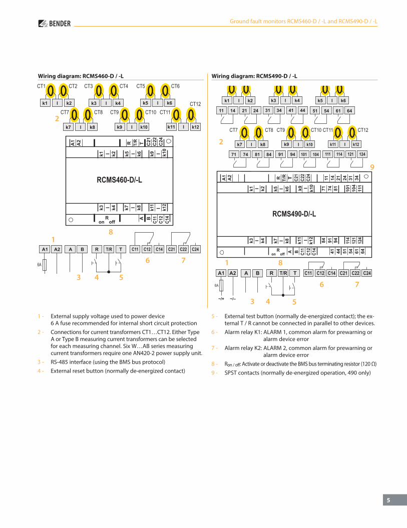
Wiring diagram: RCMS460-D / -L Wiring diagram: RCMS490-D / -L
1 - External supply voltage used to power device 6 A fuse recommended for internal short circuit protection
2 - Connections for current transformers CT1…CT12. Either Type A or Type B measuring current transformers can be selec ted for each measuring channel. Six W…AB series measuring current transformers require one AN420-2 power supply unit.
3 - RS-485 interface (using the BMS bus protocol)4 - External reset button (normally de-energized contact)
5 - External test button (normally de-energized contact); the ex-ternal T / R cannot be connected in parallel to other devices.
6 - Alarm relay K1: ALARM 1, common alarm for prewarning or alarm device error
7 - Alarm relay K2: ALARM 2, common alarm for prewarning or alarm device error
8 - Ron / off: Activate or deactivate the BMS bus terminating resistor (120 Ω)9 - SPST contacts (normally de-energized operation, 490 only)
2
2
1
3 4 5
8
6 7 1
3 4 5
6 7
9
8

6
Ground fault monitors RCMS460-D / -L and RCMS490-D / -L
Wiring, current transformers: W, WR, WS series (AC-only systems, type A)Example: W series
Wiring diagram, current transformers: WAB series (DC and AC/DC mix, type B)
Loads
Signal ConverterRCC420
Ground Fault MonitorRCMS460 / RCMS490
CurrentTransformerWF...
Optional analog output
Wiring, current transformers: WF series Wiring: digital inputs
1 - Voltage-free contact 0 > 250 Ω I < 100 Ω
2 - Current transformer input for next channel
1 2
7
Ground fault monitors RCMS460-D / -L and RCMS490-D / -L
Frequency curves and filter settings
1
2
3
4
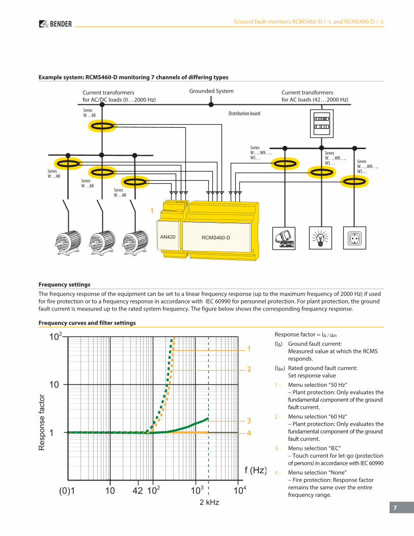
Frequency settingsThe frequency response of the equipment can be set to a linear frequency response (up to the maximum frequency of 2000 Hz) if used for fire protection or to a frequency response in accordance with IEC 60990 for personnel protection. For plant protection, the ground fault current is measured up to the rated system frequency. The figure below shows the corresponding frequency response.
Response factor = I∆ / I∆n
(I∆) Ground fault current: Measured value at which the RCMS responds.
(I∆n) Rated ground fault current: Set response value
1 - Menu selection “50 Hz” – Plant protection: Only evaluates the fundamental component of the ground fault current.
2 - Menu selection “60 Hz” – Plant protection: Only evaluates the fundamental component of the ground fault current.
3 - Menu selection “IEC” – Touch current for let-go (protection of persons) in accordance with IEC 60990
4 - Menu selection “None” – Fire protection: Response factor remains the same over the entire frequency range.
Example system: RCMS460-D monitoring 7 channels of differing types
Grounded SystemCurrent transformersfor AC/DC loads (0 2000 Hz)
Current transformersfor AC loads (42 2000 Hz)
1

8
Insulation coordination acc. to IEC 60664-1 / IEC 60664-3
Rated insulation voltage 250 VRated impulse voltage / pollution degree 4 kV / IIIProtective separation (reinforced insulation) between (A1, A2) – (k1 / l…k12 / R / RT / T, AB) – (11, 12, 14) – (21, 22, 24)Voltage test according to IEC 61010-1 2.21 kV
Supply voltage
Supply voltage US see ordering informationFrequency range US see ordering informationPower consumption ≤ 5 VA (RCMS460) / ≤ 8 VA (RCMS490)
Measuring circuit
External current transformer W…, WR…, WS… series (Type A) W…AB series (Type B)CT monitoring on / off (on)*Load 68 ΩRated insulation voltage (measuring current transformer) 800 VOperating characteristic acc. to IEC 60755 Type A and Type B depending on the CT type (Type A)*Rated frequency 0…2000 Hz (Type B) / 42…2000 Hz (Type A)Cut-off frequency none, IEC, 50 Hz, 60 Hz (none)*Measuring range 0…30 A (CT Type A) – 0…20 A (CT Type B) crest factor up to 10 A = 4, up to 20 A = 2Rated residual operating current IΔn2 (Alarm) 10 mA…10 A (Type B) 6 mA…20 A (Type A) (100 mA overcurrent)*Rated residual operating current IΔn1 (prewarning) 10…100 % x IΔn2 min 5 mA (50 %)*Digital input 1 < 100 Ω – 0 > 250 ΩPreset for alarm Offset: 0…20 A (30 mA)* and IΔ x factor 1…99 (3)*Preset for digital input 0 / I (I)*Relative percentage error 0…- 20 %Hysteresis 2…40 % (20 %)*Factor for additional CT 1…10; x 1…250 (x 1)*Number of measuring channels (per device / system) 12 / 1080
Specified timeStarting delay t (startup) per device 0…99 s (0 ms)*Response delay ton per channel 0…999 s (200 ms)*Release delay toff per channel 0…999 s (200 ms)*Operating time tae at IΔn = 1 x IΔn1 / 2 ≤ 180 msOperating time tae at IΔn = 5 x IΔn1 / 2 ≤ 30 msResponse time tan (IΔn) tan = tae + ton1 / 2Operating time I / 0 inputs < 3,5 sScanning time for all channels (IΔn) ≤ 180 msRecovery time tb 500…600 ms
Displays, memory
Display range measured value 0…30 A (CT Type A) – 0…20 A (CT Type B)Display accuracy ± 10 %LEDs ON / ALARM (RCMS4…-D) ON / ALARM / channel 1…12 (RCMS4…-L)LC display backlit graphical display (RCMS4…-D)7-segment display 2 x 7.62 mm (RCMS4…-L)History memory 300 data records (RCMS4…-D)Data logger 300 data records per channel (RCMS4…-D)Password off / 0…999 (off)*Language D, GB, F (GB)*Fault memory alarm relay on / off (off)*
Inputs / outputs
TEST / RESET button internal / externalCable length for external TEST / RESET button 0…32 ft (0…10 m)
Interface
Interface / protocol RS-485 / BMSBaud rate 9600 baudCable length 0…1200 mRecommended cable (shielded, shield on one side connected to ground) J-Y(ST)Y min. 2 x 0.8Terminating resistor 120 Ω (0.25 W) can be connected via DIP switchDevice address, BMS bus (RCMS…-D / -L) 1…90 (2)*
Cable lengths for measuring current transformers W…, WR…, WS…
Single wire ≥ AWG 18 (0.75 mm2) 0 . . . 3 ft (0…1 m)Single wire, twisted ≥ AWG 18 (0.75 mm2) 0 . . . 32 ft (0…10 m)Shielded cable ≥ AWG 20 (0.5 mm2) 0 . . . 130 ft (0…40 m)Recommended cable (shielded, shield on one side to terminal l, not connected to ground) J-Y(ST)Y min. 2 x 0.8
Cable lengths for measuring current transformers W…ABSingle wire ≥ AWG 18 (0.75 mm2) 0…32 ft (0…10 m)Connection plug-in connector, recommended WXS…
Switching elementsNumber of changeover contacts 2 SPDT contacts (RCMS460) 2 SPDT contacts, 12 SPST contacts (RCMS490)Operating principle normally energized or de-energizedElectrical service life under rated operating conditions 10.000 switching operationsContact data acc. to IEC 60947-5-1 Utilization category AC-13 AC-14 DC-12 DC-12 DC-12 Rated operational voltage 230 V 230 V 24 V 110 V 220 V Rated operational current 5 A 3 A 1 A 0.2 A 0.1 AMinimum contact load 1 mA at AC / DC ≥ 10 V
Environment / EMCEMC IEC 62020: 2003-11Operating temperature - 13 °F…+ 131 °F (- 25 °C…+ 55 °C )Climatic class acc. to IEC 60721 Stationary use (IEC 60721-3-3) 3K5 (except condensation and formation of ice) Transport (IEC 60721-3-2) 2K3 (except condensation and formation of ice) Long-time storage (IEC 60721-3-1) 1K4 (except condensation and formation of ice)Classification of mechanical conditions IEC 60721 Stationary use (IEC 60721-3-3) 3M4 Transport (IEC 60721-3-2) 2M2 Long-time storage (IEC 60721-3-1) 1M3
Connection
Connection screw terminalsrigid / flexible AWG 24…12 / 24 . . . 14Multi-conductor connection (two conductors of the same cross section) rigid / flexible AWG 24…12 / 24…12Stripping length 8…9 mmTightening torque 0.5…0.6 Nm
OtherOperating mode continuous operationPosition of normal use anyDegree of protection, internal components (IEC 60529) IP30, NEMA 1Degree of protection, terminals (IEC 60529) IP20, NEMA 1Enclosure material polycarbonateFlammability class UL94V-0Screw mounting 2 x M4DIN rail mounting acc. to IEC 60715Standards IEC 62020Technical manual TGH 1393Weight ≤ 0.8 lb (RCMS460) ≤ 1.2 lb (RCMS490)
( )* Factory setting
Ground fault monitors RCMS460-D / -L and RCMS490-D / -L
Technical data
9
Ground fault monitors RCMS460-D / -L and RCMS490-D / -L
Ordering informationType Supply voltage US* Art. No.RCMS460-D-1 DC 16…94 V AC 42…460 Hz 16…72 V B 9405 3001RCMS460-D-2 DC 70…276 V AC 42…460 Hz 70…276 V B 9405 3002RCMS460-L-1 DC 16…94 V AC 42…460 Hz 16…72 V B 9405 3003RCMS460-L-2 DC 70…276 V AC 42…460 Hz 70…276 V B 9405 3004RCMS490-D-1 DC 16…94 V AC 42…460 Hz 16…72 V B 9405 3005RCMS490-D-2 DC 70…276 V AC 42…460 Hz 70…276 V B 9405 3006RCMS490-L-1 DC 16…94 V AC 42…460 Hz 16…72 V B 9405 3007RCMS490-L-2 DC 70…276 V AC 42…460 Hz 70…276 V B 9405 3008
Type Supply voltage US* Art. No.AN420-2 (power supply unit for six W…AB)
DC 70…276 V / AC 42…460 Hz 70…276 V
B 9405 3100
Connector cable for RCMS, "AB" type current transformers, and AN420 power supplyType Length in ft (m) Ordering No.WXS-100 3' (1) B 5111 00028WXS-250 8' (2.5) B 5111 00029WXS-500 16' (5) B 5111 00030WXS-1000 32' (10) B 5111 00027WXS-1500 50' (15) B 5111 00035
Current transformers, DC and AC/DC mix (Type B)Type Inside diameter in inches (mm) Ordering No.W20AB ø 0.75" (20) B 9808 0008W35AB ø 1.35" (35) B 9808 0016W60AB ø 2.25" (60) B 9808 0026W120AB ø 4.7" (120) B 9808 0041W210AB ø 8.25" (210) B 9808 0040
Current transformers, AC-only system (Type A)Type Inside diameter in inches (mm) Ordering No.W20 ø 0.75" (20) B 9808 0003W35 ø 1.35" (35) B 9808 0010W60 ø2.25" (60) B 9808 0018W120 ø 4.7" (120) B 9808 0028W210 ø 8.25" (210) B 9808 0034WR70x175 2.75" x 6.9" (70 x 175) B 9808 0609WR115x305 4.5" x 12" (115 x 305) B 9808 0610WS20x30 (split-core) 0.75" x 1.35" (20 x 30) B 9808 0601WS50x80 (split-core) 2" x 3.1" (50 x 80) B 9808 0603WS80x120 (split-core) 3.1" x 4.7" (80 x 120) B 9808 0606
Other current transformer types on request.
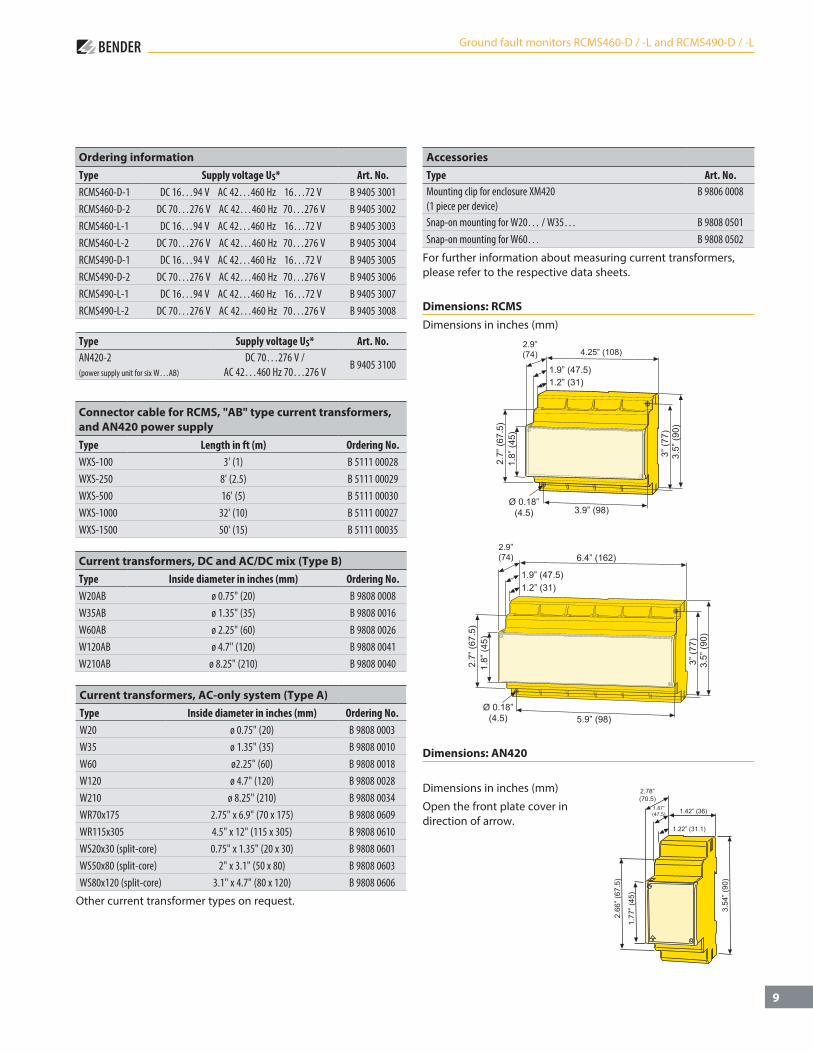
Dimensions: RCMSDimensions in inches (mm)
1.9” (47.5)1.2” (31)
2.7”
(67.
5)1.
8” (4
5)Ø 0.18”
(4.5) 3.9” (98)
3” (7
7)3.
5” (9
0)
4.25” (108)2.9”(74)
1.9” (47.5)1.2” (31)
2.7”
(67.
5)1.
8” (4
5)
Ø 0.18”(4.5)
3” (7
7)3.
5” (9
0)
5.9” (98)
6.4” (162)2.9”(74)
Dimensions: AN420
1.42” (36)
2.78”(70.5)
1.87”(47.5)
1.22” (31.1)
2.66
” (67
.5)
1.77
” (45
)
3.54
” (90
)
Dimensions in inches (mm)
Open the front plate cover in direction of arrow.
AccessoriesType Art. No.Mounting clip for enclosure XM420 (1 piece per device)
B 9806 0008
Snap-on mounting for W20… / W35… B 9808 0501Snap-on mounting for W60… B 9808 0502
For further information about measuring current transformers, please refer to the respective data sheets.

Doc
umen
t NA
E104
2060
/ 04
.201
3 / ©
Ben
der I
nc.
T M
Canada • Mississauga, ONToll-Free: 800-243-2438 • Main: 905-602-9990
Fax: 905-602-9960 • E-mail: [email protected]
USA • Coatesville, PAToll-Free: 800-356-4266 • Main: 610-383-9200Fax: 610-383-7100 • E-mail: [email protected]
bender.org • bender.org/mobile