Product presentation - inventlab
34
inventlab ® Product presentation UPS and power supply solutions
Transcript of Product presentation - inventlab
inventlab®
Product presentation
UPS and power supply solutions

inventlab LLC | CH-4702 Oensingen | +41 62 544 68 05 | www.inventlab.ch | [email protected] | CHE-398.256.369 MWST2
inventlab LLC product overview
inventlab LLCSolothurnstrasse 6CH-4702 Oensingen+41 62 544 68 [email protected]
ATX UPSU ATX UPSU IPC 20W UPSU
®® ®®
MIL UPSUPC104 UPSUmodules
PC1
04 P
S A
TXP
C104
com
mun
icat
ion
PC1
04 V
REG
PC1
04 U
PSU
®
PCB UPSU
®
10A UPSU
Integration modules
ippc
cis
tic
siu
b

inventlab LLC | CH-4702 Oensingen | +41 62 544 68 05 | www.inventlab.ch | [email protected] | CHE-398.256.369 MWST3
Content
3
inventlab LLC product overview 2Content 3Why ultracapacitor based solutions? 4ATX UPSU 5ATX UPSU: Accessories 6ATX UPSU: Specifications, connectors 7ATX UPSU AC: ATX power supply with integrated ATX UPSU 8ATX UPSU IPC 9ATX UPSU IPC: Variants, accessories, specifications 1010A UPSU 1110A UPSU: Block diagramm, connectors 1220W UPSU 1320W UPSU: Timing parameters, configuration software 1420W UPSU: Specifications, connectors 15PC104 UPSU modules 16PC104 UPSU modules: Module combinations and block diagram 17PC104 VREG 18PC104 UPSU 19PC104 communication 20PC104 PS ATX 21MIL UPSU 22MIL UPSU: Block diagram 23MIL UPSU: Mounting, specifications 24PCB UPSU 25inventlab integration modules 26iub - inventlab ultracapacitor buffer 27ippcc - inventlab power path controller and charger 28ippcc: Block diagramm, connectors and application example 29ist - inventlab schmitt trigger module 30ist: Block diagram, dimensions and connectors 31ics - inventlab current sensing module 32ics: Block diagram, dimensions and connectors 33More informations / Your project / Where to buy 34
This presentation provides a general overview over the inventlab-products.For more details like datasheets, configuration software and 3D models, see product websites or contact inventlab LLC.Your special requirements are also welcome.
Presentation content
All inventlab products are 100% Swiss made.
Swiss made

inventlab LLC | CH-4702 Oensingen | +41 62 544 68 05 | www.inventlab.ch | [email protected] | CHE-398.256.369 MWST4
Why ultracapacitor based solutions?
Maintenance-free Wide operating temperature-range Fast charge Non-chemical energy storage Fast discharge (high power density) No storage problems No deep discharge High cycle life Low ESR
Key Benefits
Maxwell supercaps. 310F (behind) and 350F
At remote locations or when battery replacement is expensive If high-availability, reliability, and/or long life is required If high efficiency (low ESR, high power density) is required If high cycle life is required In low temperature environments Fast charge/fast availability is required No chemical energy storage can/should be used When expensive power transmission lines for periodically high
currents can be dropped User friendly applications that should automatically shut down
correctly in the event of power failure
When are ultracapacitors required?
Typical specifications of a single supercap cell
>10 years lifetime (20% capacitance change) - 40°C to 70°C operating temperature 2.7V maximum voltage Capacitance >300F >=500k cycle life >=200A maximum current <=4mΩ ESR
Note: Specifications can be extremely different depending on Ultracapacitor.
inventlab LLC | CH-4702 Oensingen | +41 62 544 68 05 | www.inventlab.ch | [email protected] | CHE-398.256.369 MWST5
ATX UPSU
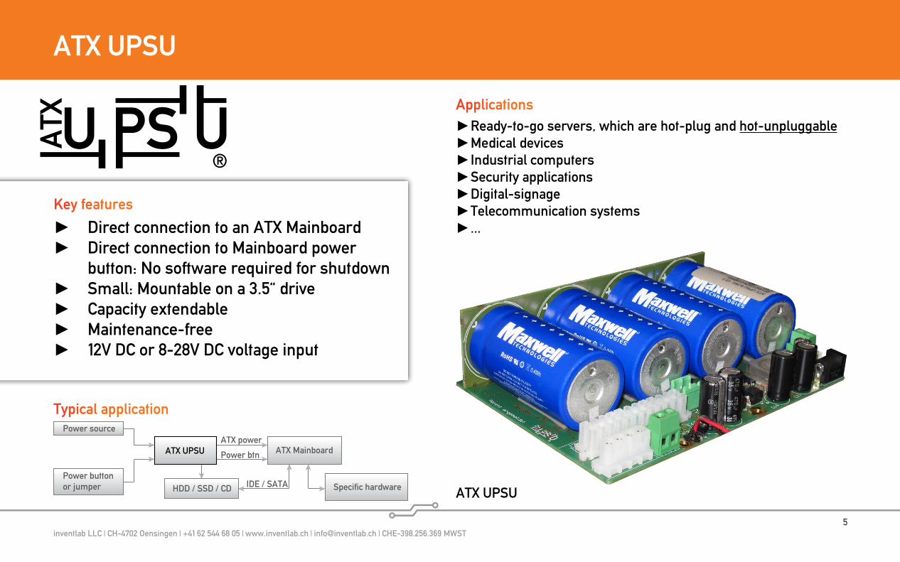
Ready-to-go servers, which are hot-plug and hot-unpluggable Medical devices Industrial computers Security applications Digital-signage Telecommunication systems ...
Applications
ATX UPSU
Direct connection to an ATX Mainboard Direct connection to Mainboard power
button: No software required for shutdown Small: Mountable on a 3.5“ drive Capacity extendable Maintenance-free 12V DC or 8-28V DC voltage input
Key features
Power source
ATX MainboardATX power
Power btn
Power buttonor jumper HDD / SSD / CD Specific hardwareIDE / SATA
ATX UPSU
Typical application
®

inventlab LLC | CH-4702 Oensingen | +41 62 544 68 05 | www.inventlab.ch | [email protected] | CHE-398.256.369 MWST6
ATX UPSU: Accessories
PC POWER SUPPLY TO ATX UPSU adapter: For direct powe-ring ATX UPSU by a normal ATX power supply.
ATX UPSU CAP EXTENSION KIT: Increases capacity
®
ATX UPSU BATTERY PACK: In-creases capacity
Mounting kits
inventlab LLC | CH-4702 Oensingen | +41 62 544 68 05 | www.inventlab.ch | [email protected] | CHE-398.256.369 MWST7
ATX UPSU: Specifications, connectors
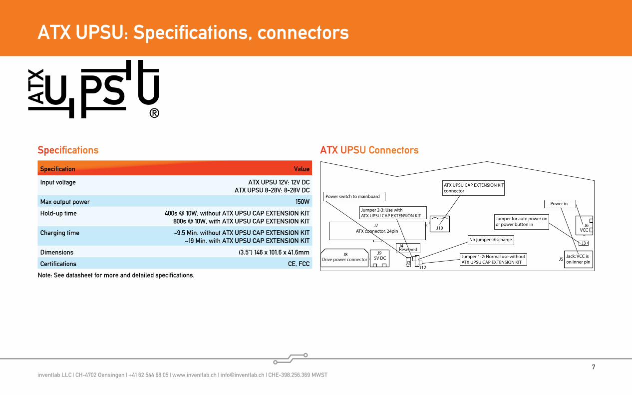
Specification Value
Input voltage ATX UPSU 12V: 12V DCATX UPSU 8-28V: 8-28V DC
Max output power 150W
Hold-up time 400s @ 10W, without ATX UPSU CAP EXTENSION KIT800s @ 10W, with ATX UPSU CAP EXTENSION KIT
Charging time ~9.5 Min. without ATX UPSU CAP EXTENSION KIT~19 Min. with ATX UPSU CAP EXTENSION KIT
Dimensions (3.5“) 146 x 101.6 x 41.6mm
Certifications CE, FCC
Note: See datasheet for more and detailed specifications.
ATX connector, 24pin
Drive power connector
Reserved
5V DC
ATX UPSU CAP EXTENSION KIT connector
Power switch to mainboard
No jumper: discharge
Jumper for auto power onor power button in
Power in
VCC
Jack: VCC ison inner pin
Jumper 1-2: Normal use withoutATX UPSU CAP EXTENSION KIT
Jumper 2-3: Use withATX UPSU CAP EXTENSION KIT
J12J2
J3
J8
J7 J10
J9
J6
J5
J4
Specifications ATX UPSU Connectors
®
inventlab LLC | CH-4702 Oensingen | +41 62 544 68 05 | www.inventlab.ch | [email protected] | CHE-398.256.369 MWST8
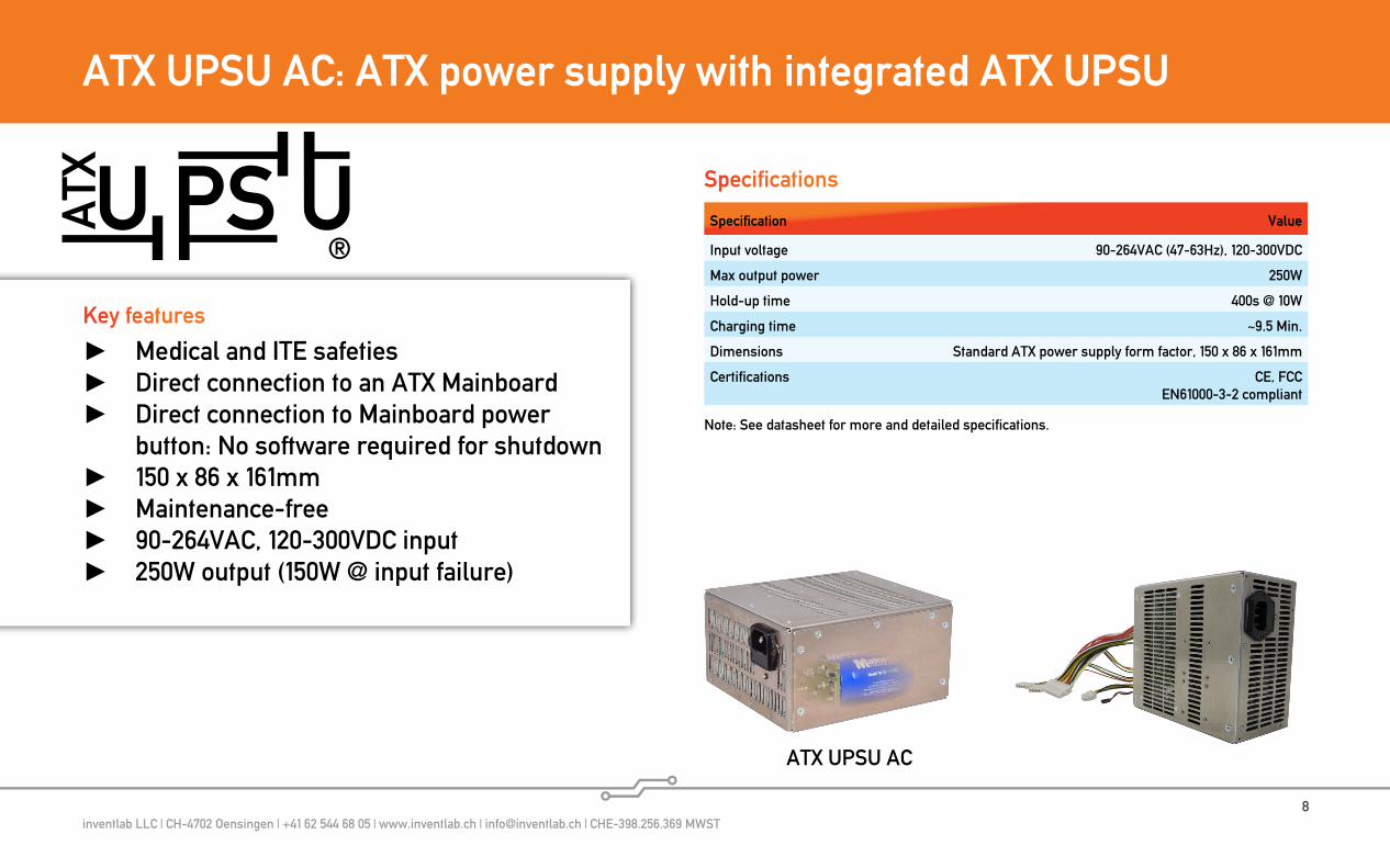
ATX UPSU AC: ATX power supply with integrated ATX UPSU
®
Medical and ITE safeties Direct connection to an ATX Mainboard Direct connection to Mainboard power
button: No software required for shutdown 150 x 86 x 161mm Maintenance-free 90-264VAC, 120-300VDC input 250W output (150W @ input failure)
Key features
Specification Value
Input voltage 90-264VAC (47-63Hz), 120-300VDC
Max output power 250W
Hold-up time 400s @ 10W
Charging time ~9.5 Min.
Dimensions Standard ATX power supply form factor, 150 x 86 x 161mm
Certifications CE, FCCEN61000-3-2 compliant
Note: See datasheet for more and detailed specifications.
Specifications
ATX UPSU AC
inventlab LLC | CH-4702 Oensingen | +41 62 544 68 05 | www.inventlab.ch | [email protected] | CHE-398.256.369 MWST9
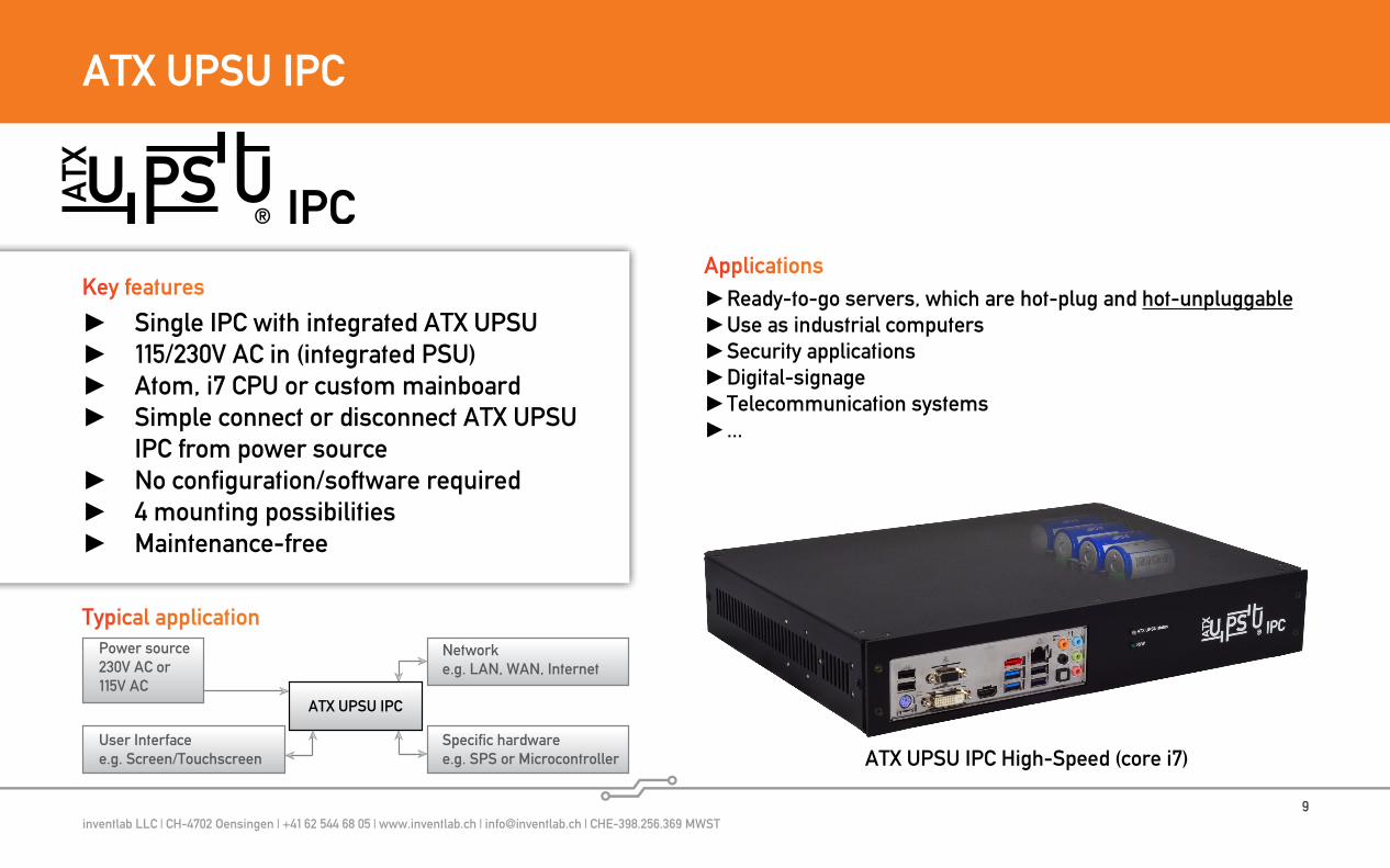
ATX UPSU IPC
Single IPC with integrated ATX UPSU 115/230V AC in (integrated PSU) Atom, i7 CPU or custom mainboard Simple connect or disconnect ATX UPSU
IPC from power source No configuration/software required 4 mounting possibilities Maintenance-free
Key features Ready-to-go servers, which are hot-plug and hot-unpluggable Use as industrial computers Security applications Digital-signage Telecommunication systems ...
Applications
ATX UPSU IPC High-Speed (core i7)
Power source230V AC or115V AC
Specific hardwaree.g. SPS or Microcontroller
Networke.g. LAN, WAN, Internet
ATX UPSU IPC
User Interfacee.g. Screen/Touchscreen
Typical application
inventlab LLC | CH-4702 Oensingen | +41 62 544 68 05 | www.inventlab.ch | [email protected] | CHE-398.256.369 MWST10
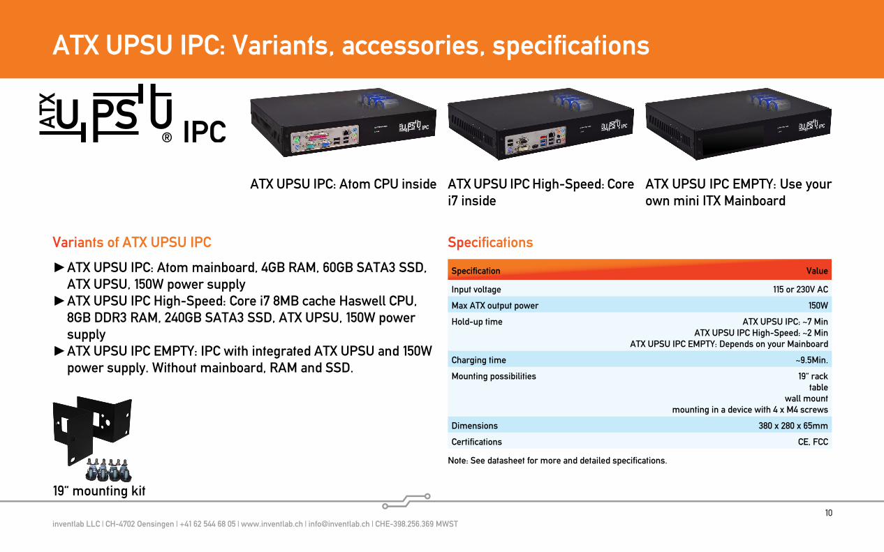
ATX UPSU IPC: Variants, accessories, specifications
19“ mounting kit
ATX UPSU IPC EMPTY: Use your own mini ITX Mainboard
Specification Value
Input voltage 115 or 230V AC
Max ATX output power 150W
Hold-up time ATX UPSU IPC: ~7 MinATX UPSU IPC High-Speed: ~2 Min
ATX UPSU IPC EMPTY: Depends on your Mainboard
Charging time ~9.5Min.
Mounting possibilities 19“ racktable
wall mountmounting in a device with 4 x M4 screws
Dimensions 380 x 280 x 65mm
Certifications CE, FCC
Specifications
Note: See datasheet for more and detailed specifications.
Variants of ATX UPSU IPC
ATX UPSU IPC: Atom mainboard, 4GB RAM, 60GB SATA3 SSD, ATX UPSU, 150W power supply
ATX UPSU IPC High-Speed: Core i7 8MB cache Haswell CPU, 8GB DDR3 RAM, 240GB SATA3 SSD, ATX UPSU, 150W power supply
ATX UPSU IPC EMPTY: IPC with integrated ATX UPSU and 150W power supply. Without mainboard, RAM and SSD.
ATX UPSU IPC: Atom CPU inside ATX UPSU IPC High-Speed: Core i7 inside

inventlab LLC | CH-4702 Oensingen | +41 62 544 68 05 | www.inventlab.ch | [email protected] | CHE-398.256.369 MWST11
10A UPSU
UPS solution with integrated energy storage 12V and 24V variants Ultracapacotor and battery variants 120W (12V variants) / 160W (24V variants) PC104 or DIN-Rail case variants USB communication Relais signal outputs Wide temperature range: -30°C to +60°C
Key features
10A UPSU xxV / 10A UPSU xxV B
10A UPSU xxV B(Battery variants)
10A UPSU xxV(Ultracapacitor variants)
®
10A UPSU xxV DIN / 10A UPSU xxV B DIN

inventlab LLC | CH-4702 Oensingen | +41 62 544 68 05 | www.inventlab.ch | [email protected] | CHE-398.256.369 MWST12
10A UPSU: Block diagramm, connectors
voltage input12V / 24V
Supercapsor Batteries
Controller,charger,voltage regulator
power failedUSB
Status LED
voltage output12V / 24V
low capacity
Ideal diodewith MOSFET
10A UPSU
USB
Stat
us L
ED
volta
ge in
volta
ge o
utpo
wer
faile
dlo
w c
apac
ity
- -
Block diagram Connectors
®
inventlab LLC | CH-4702 Oensingen | +41 62 544 68 05 | www.inventlab.ch | [email protected] | CHE-398.256.369 MWST13
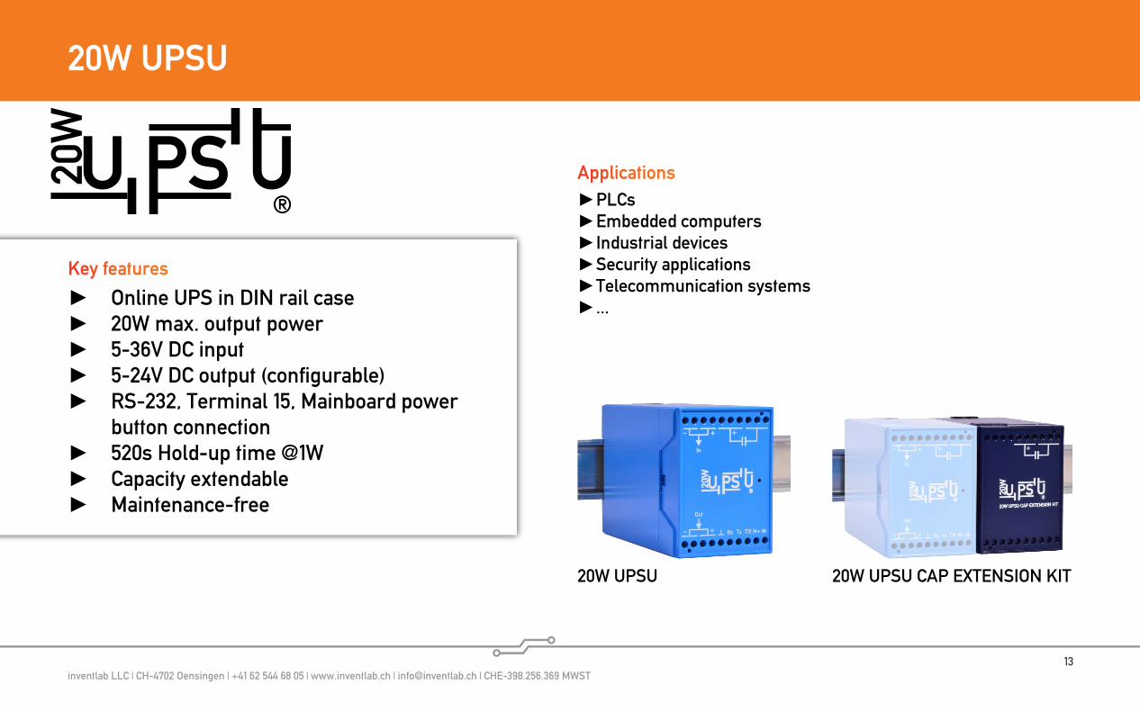
20W UPSU
®
Online UPS in DIN rail case 20W max. output power 5-36V DC input 5-24V DC output (configurable) RS-232, Terminal 15, Mainboard power
button connection 520s Hold-up time @1W Capacity extendable Maintenance-free
Key features
20W UPSU
PLCs Embedded computers Industrial devices Security applications Telecommunication systems ...
Applications
20W UPSU CAP EXTENSION KIT
inventlab LLC | CH-4702 Oensingen | +41 62 544 68 05 | www.inventlab.ch | [email protected] | CHE-398.256.369 MWST14
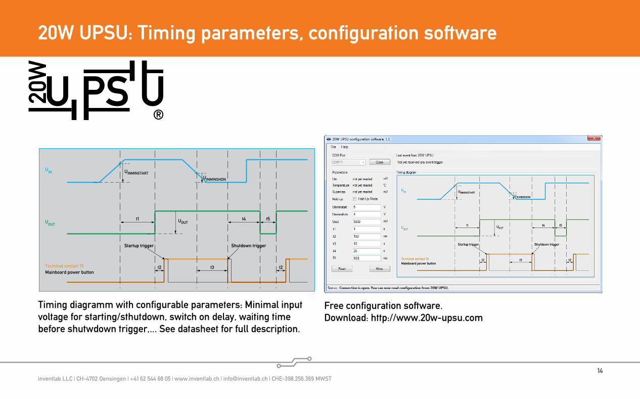
20W UPSU: Timing parameters, configuration software
UIN
UOUT
Terminal contact 15
t1
t3Mainboard power button
t1: Time to charge with full power before the output switches on. Note: The output goes not high until the supercap has reached the minimal voltage to switch the output voltage on. If t1 is set to its min value 0, the output switches on as fast as possible. The higher the t1 is set, the earlier the supercap is fully charged but the later the output switches on after powering 20W UPSU. Range: 0-65535, default: 90st2: The trigger to switch the device on fires after UOUT reaches the setpoint UOUT voltage and t2 is over. Range: 0-65535ms, default: 100msUOUT : The output voltage. UOUT can be 5V, 7.5V, 9V, 12V, 15V, 19V, 24V, xV. If set to xV, you can set the output voltage by the internal potentiometer to a value between 5V and 24V. Default: 5V t3: The time before the shutdown is triggered after UIN was failed. If the input voltage goes high again before t3 is over, the shutdown trigger will not fire. If UIN was failed and the caps are not fully charged, t3 will be ignored and the shutdown trigger fires immediately. If UIN was failed and the shutdown trigger was still fired before, t3 will be ignored and the shutdown trigger will not be fired again. In this case, after the time of t4, the otput goes down for the time of t5. Then the output voltage goes high again and after the time of t2 the startup trigger will be fired. T3 calculate formula: t3 = Running time by max power consumption of connected device - t4 = tLOADMAX - t4 Range: 0-65535s, default: 1st4: The shutdown time. If power input is back again and the shutdown was triggered before: T4 is the minimal hold up time to hold the UOUT high, before it can go down for the time of t5. If power input is not back and the shutdown trigger was fired: The output voltage stays high for the time of t4. Note: If t4 is higher than the supercap can hold UOUT high, UOUT goes down earlier than t4. T4 calculate formula: t4 = Duration to shutdown x 1.5 = tSHDN x 1.5 Range: 1-255s, default: 30st5: The minimal waiting time after UOUT was going down, before a new startup trigger fires. Set t5 enough long, that your device can reset and restart in definied state. Range: 0-65535ms, default: 1000msUINMINSTART : The minimal input voltage to start t1. UIN < UINMINSTART means no input voltage available. UINMINSTART has to be set higher than UINMINSHDN. Range: 4-36V, default: 4VUINMINSHDN : The minimal input voltage, which is necessary to not start t3. UIN < UINMINSHDN means UIN is failed. Range: 3-36V, default: 3VNotes: If the device is set to the hold-up mode, the output voltage is hold up as long as possible. In this case, terminal contact 15 goes up if UIN is up and goes down if UIN goes down. The mainboard power button fires on every state change of UIN, while the RS232 sends every state change to the device. Set t4 enough high to shutdown your device and add about 50% reserve time. Set the sum of t3 and t4 low enough, that the supercap can hold UOUT long enough high with your load. See calculate formulas.
t2
t4 t5
t2
UINMINSTARTUINMINSHDN
UOUT
® Timing diagram
V 1.0www.20w-upsu.com | [email protected] | A product by ChypsoTech LCC
Startup trigger Shutdown trigger
Timing diagramm with configurable parameters: Minimal input voltage for starting/sthutdown, switch on delay, waiting timebefore shutwdown trigger,... See datasheet for full description.
Free configuration software.Download: http://www.20w-upsu.com
®

inventlab LLC | CH-4702 Oensingen | +41 62 544 68 05 | www.inventlab.ch | [email protected] | CHE-398.256.369 MWST15
20W UPSU: Specifications, connectors
Rx Tx T15 M+ M-
- +
®
+
- +
In
Out
Volta
ge in
put
5 to 3
6V D
C
Conn
ectio
n to
20W
UPSU C
AP
EXTE
NSION K
IT
Volta
ge ou
tput
to de
vice GND
RS232 R
xRS23
2 Tx
Term
inal
15 co
nnec
tion
Mainbo
ard p
ower
butto
n +
Mainbo
ard p
ower
butto
n -
1 2 3 4 5 6 7 8 9 10
11 12 13 14 15 19181716 20
Status LEDGreen flashing: Charging, output offGreen light: Normal use, output onRed flashing: Power in failure, output onRed fast flashing: Temperature too highRed light: Error occured, 20W UPSU defect
® Connectors
V 1.0www.20w-upsu.com | [email protected] product by ChypsoTech LCC
®
Specification Value
Input voltage 5-36V DC
Output voltage 5-24V DC
Max power consumption 45W
Max output power 20W
Hold-up time 520s @ 1W, without 20W UPSU CAP EXTENSION KIT26s @ 20W, without 20W UPSU CAP EXTENSION KIT
Charging time ~90s without 20W UPSU CAP EXTENSION KIT
Dimensions 55 (width) x 75 x 109,5 mm
Specifications
Note: Hold-up time and charging time increases linearly by attaching one or more 20W UPSU CAP EXTENSION KIT. See datasheet for more and detailed specifications.
Connectors
inventlab LLC | CH-4702 Oensingen | +41 62 544 68 05 | www.inventlab.ch | [email protected] | CHE-398.256.369 MWST16
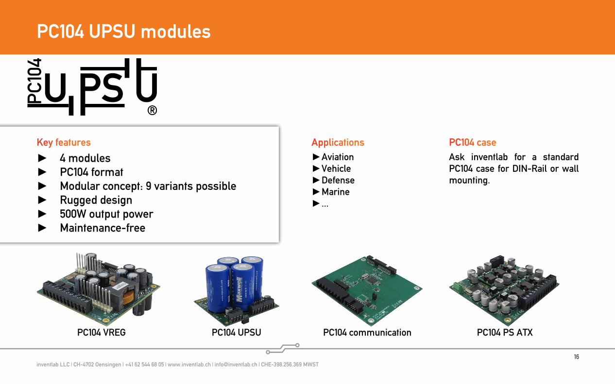
PC104 UPSU modules
®
4 modules PC104 format Modular concept: 9 variants possible Rugged design 500W output power Maintenance-free
Key features
PC104 VREG
Aviation Vehicle Defense Marine ...
Applications
PC104 PS ATXPC104 UPSU PC104 communication
PC104 caseAsk inventlab for a standard PC104 case for DIN-Rail or wall mounting.

inventlab LLC | CH-4702 Oensingen | +41 62 544 68 05 | www.inventlab.ch | [email protected] | CHE-398.256.369 MWST17
PC104 UPSU modules: Module combinations and block diagram
PC104 UPSU
Charge Discharge
ATX Mainboard
PC104 communication
ATX
PC104 VREG
4-36V(with UPSU: 11-36V)
5-36Voutput voltageconfigurableeither by jumper or by PC104 communication
RS232/RS4xxOptoisolated signals:run, fail, low capacity,mainboard pwr btn
PC104 PS ATX
12V
or
Max 500W or 50A
Load/Customer‘s device
to optional additionalcap module
PC104 UPSU-Stack block diagramPossible module combinations
®
Option #
VREG UPSUcom-muni-cation
PS ATX Application
1 1 0 0 0 Transient protection, voltage regulation
2 1 0 0 1 Transient protection, voltage regulation, ATX voltage output
3 1 0 1 0 Transient protection, voltage regulation, communica-tion with PC104 VREG
4 1 0 1 1 Transient protection, voltage regulation, ATX voltage output, communication with PC104 VREG
5 1 1 0 0 Transient protection, voltage regulation, UPS function
6 1 1 0 1 Transient protection, voltage regulation, UPS function, ATX voltage output
7 1 1 1 0 Transient protection, voltage regulation, UPS function, communication with PC104 VREG and PC104 UPSU
8 1 1 1 1 Transient protection, voltage regulation, UPS function, communication with PC104 VREG and PC104 UPSU, ATX voltage output
9 0 0 0 1 12VDC input, ATX voltage output
The PC104 UPSU-modules-stack contains four modules. These four modules can be combined together to meet the customer specific requirements.
inventlab LLC | CH-4702 Oensingen | +41 62 544 68 05 | www.inventlab.ch | [email protected] | CHE-398.256.369 MWST18
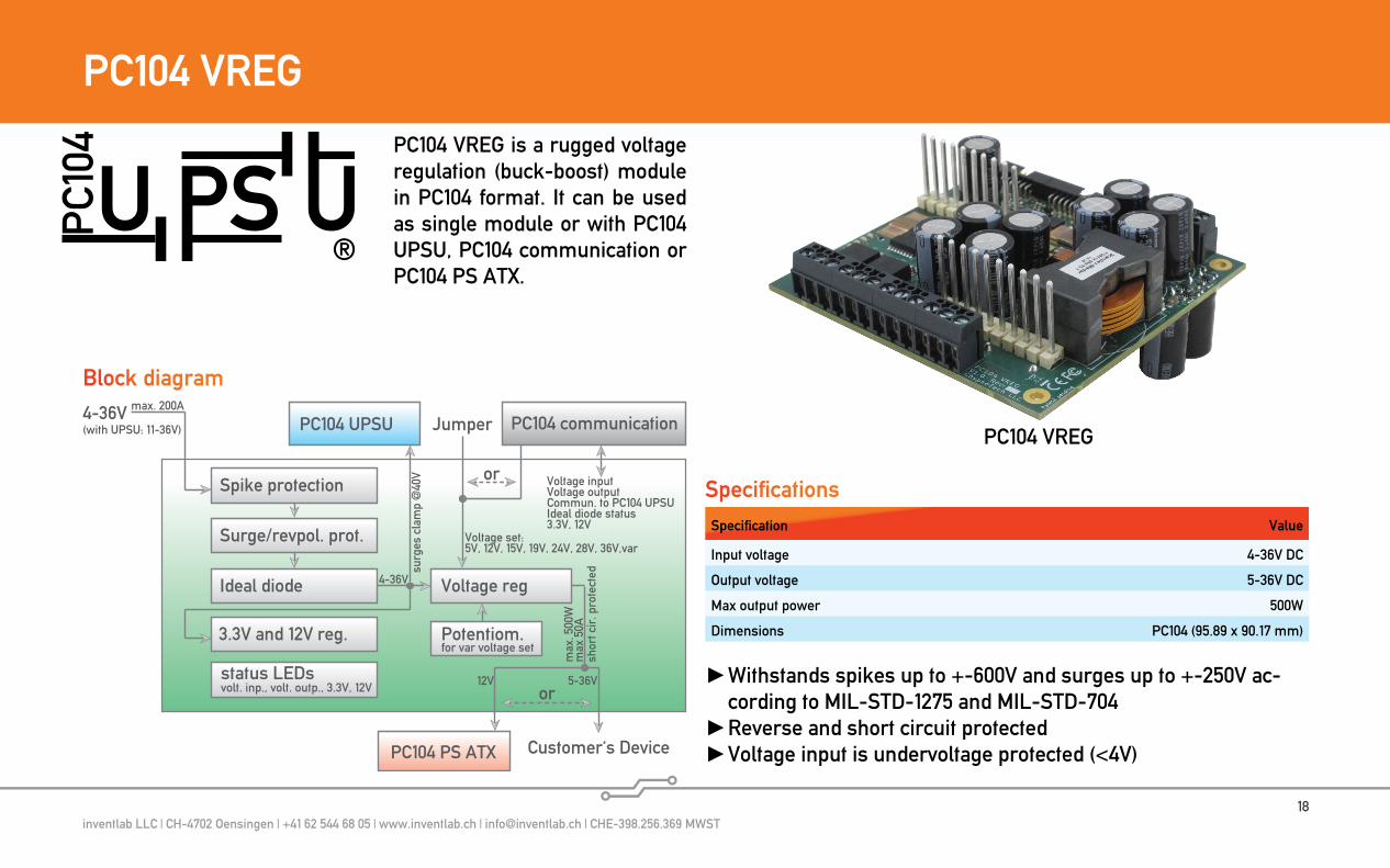
PC104 VREG
3.3V and 12V reg.
max
. 500
Wm
ax 5
0AIdeal diode
Surge/revpol. prot.
Spike protection
status LEDs
Voltage reg
12V 5-36V
surg
es c
lam
p @
40V
4-36V(with UPSU: 11-36V) PC104 communicationPC104 UPSU
PC104 PS ATX
4-36V
Customer‘s Device
or
shor
t cir
. pro
tect
ed
volt. inp., volt. outp., 3.3V, 12V
Voltage inputVoltage outputCommun. to PC104 UPSUIdeal diode status3.3V, 12V
Jumper
Voltage set:5V, 12V, 15V, 19V, 24V, 28V, 36V,var
Potentiom.for var voltage set
or
max. 200A
®
Block diagram
PC104 VREG
Specification Value
Input voltage 4-36V DC
Output voltage 5-36V DC
Max output power 500W
Dimensions PC104 (95.89 x 90.17 mm)
Specifications
Withstands spikes up to +-600V and surges up to +-250V ac- cording to MIL-STD-1275 and MIL-STD-704
Reverse and short circuit protected Voltage input is undervoltage protected (<4V)
PC104 VREG is a rugged voltage regulation (buck-boost) module in PC104 format. It can be used as single module or with PC104 UPSU, PC104 communication or PC104 PS ATX.
inventlab LLC | CH-4702 Oensingen | +41 62 544 68 05 | www.inventlab.ch | [email protected] | CHE-398.256.369 MWST19
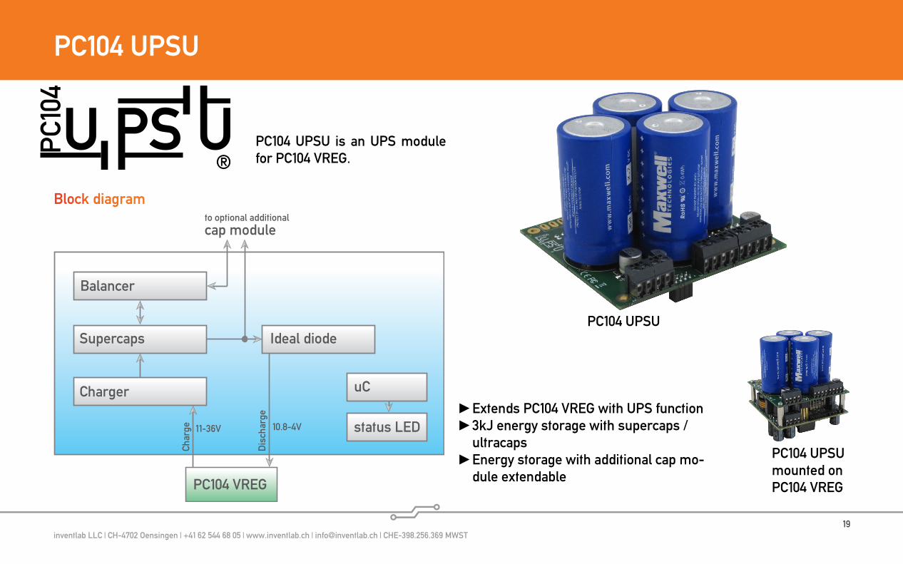
PC104 UPSU
Supercaps
Char
ge
Balancer
Charger
status LED
Ideal diode
uC
11-36V
PC104 VREG
to optional additionalcap module
Dis
char
ge
10.8-4V
®
Block diagram
PC104 UPSU
PC104 UPSU mounted on PC104 VREG
Extends PC104 VREG with UPS function 3kJ energy storage with supercaps /
ultracaps Energy storage with additional cap mo-
dule extendable
PC104 UPSU is an UPS module for PC104 VREG.

inventlab LLC | CH-4702 Oensingen | +41 62 544 68 05 | www.inventlab.ch | [email protected] | CHE-398.256.369 MWST20
PC104 communication
RS4XX PHY
Volta
ge s
et
RS232 PHY
uc
status LED
PC104 VREG
Com
mun
i-ca
tion
Signals:runfaillow capacitymainboard pwr btn
or
Load/Customer‘s device
Optoisolator
signal LEDs
Temperature sens.U
IN
UOUT
Power fail signal
t1
t3
Mainboard power button signal
t2
t4 t5
t2
UINMINSTARTUINMINSHDN
UOUT
Startup trigger Shutdown trigger
Run signal (≈ terminal contact 15)
Low capacity signal
USUPERCAP USUPERCAPGOOD
USUPERCAPBAD
tMBPWRBTN
®
Block diagram
PC104 communication
Timing diagram
RS-4xx/RS-232 Optoisolated (5kVr.m.s.) Sig-
nal outputs: Low capacity, power fail, run, mainboard power button
Intelligent behavior configu- ration options
PC104 communication is a com-munication and controlling mo-dule for PC104 VREG.
inventlab LLC | CH-4702 Oensingen | +41 62 544 68 05 | www.inventlab.ch | [email protected] | CHE-398.256.369 MWST21
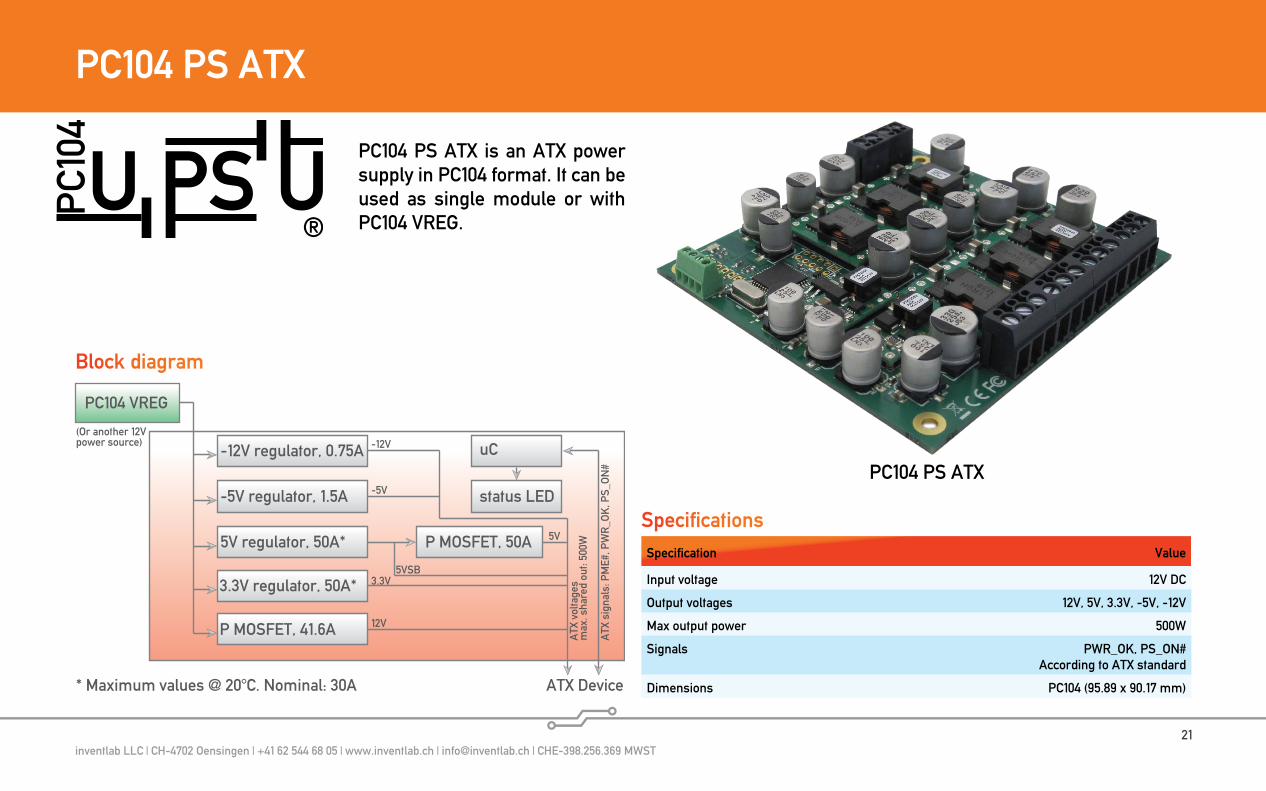
PC104 PS ATX
ATX Device
3.3V regulator, 50A*A
TX v
olta
ges
max
. sha
red
out:
500W
(Or another 12Vpower source)
ATX
sig
nals
: PM
E#, P
WR
_OK
, PS_
ON
#
5V regulator, 50A*
-5V regulator, 1.5A
-12V regulator, 0.75A
P MOSFET, 41.6A
status LED
P MOSFET, 50A
uC
5VSB3.3V
12V
5V
-5V
-12V
PC104 VREG
* Maximum values @ 20°C. Nominal: 30A
®
Block diagram
PC104 PS ATX
Specification Value
Input voltage 12V DC
Output voltages 12V, 5V, 3.3V, -5V, -12V
Max output power 500W
Signals PWR_OK, PS_ON#According to ATX standard
Dimensions PC104 (95.89 x 90.17 mm)
Specifications
PC104 PS ATX is an ATX power supply in PC104 format. It can be used as single module or with PC104 VREG.
inventlab LLC | CH-4702 Oensingen | +41 62 544 68 05 | www.inventlab.ch | [email protected] | CHE-398.256.369 MWST22
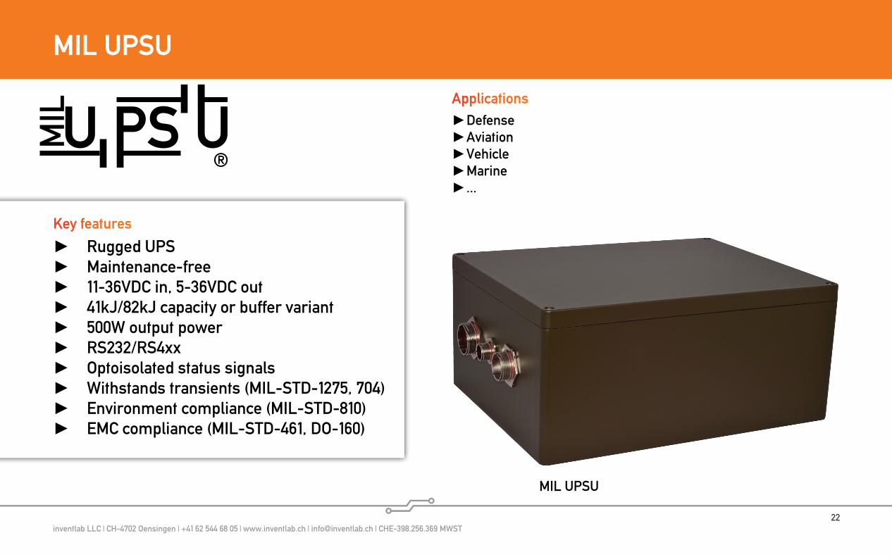
MIL UPSU
®
Rugged UPS Maintenance-free 11-36VDC in, 5-36VDC out 41kJ/82kJ capacity or buffer variant 500W output power RS232/RS4xx Optoisolated status signals Withstands transients (MIL-STD-1275, 704) Environment compliance (MIL-STD-810) EMC compliance (MIL-STD-461, DO-160)
Key features
Defense Aviation Vehicle Marine ...
Applications
MIL UPSU
inventlab LLC | CH-4702 Oensingen | +41 62 544 68 05 | www.inventlab.ch | [email protected] | CHE-398.256.369 MWST23
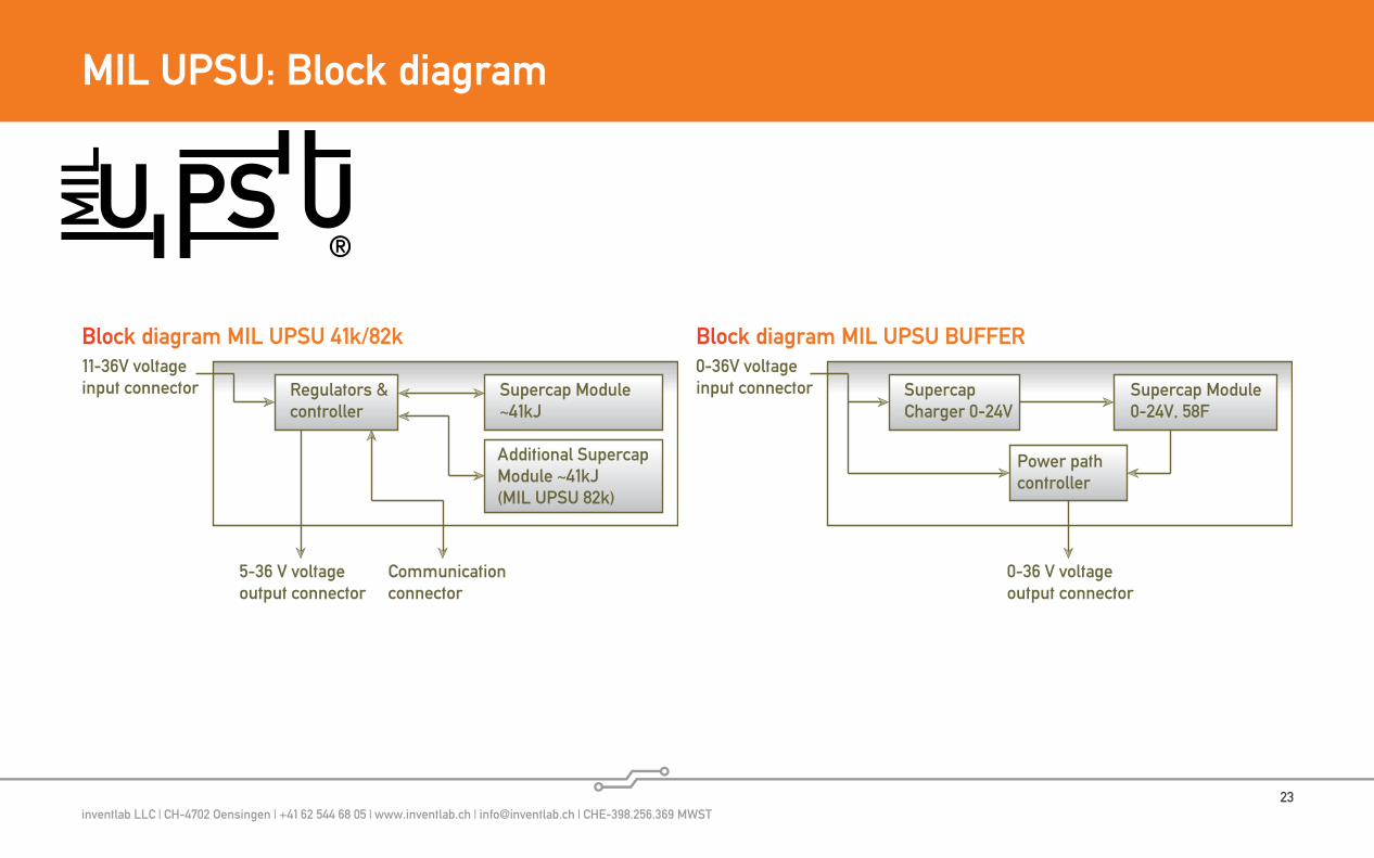
MIL UPSU: Block diagram
®
11-36V voltageinput connector Supercap Module
~41kJ
Communicationconnector
Regulators &controller
5-36 V voltageoutput connector
Additional Supercap Module ~41kJ(MIL UPSU 82k)
Block diagram MIL UPSU 41k/82k0-36V voltageinput connector Supercap Module
0-24V, 58FSupercapCharger 0-24V
0-36 V voltageoutput connector
Power pathcontroller
Block diagram MIL UPSU BUFFER
inventlab LLC | CH-4702 Oensingen | +41 62 544 68 05 | www.inventlab.ch | [email protected] | CHE-398.256.369 MWST24
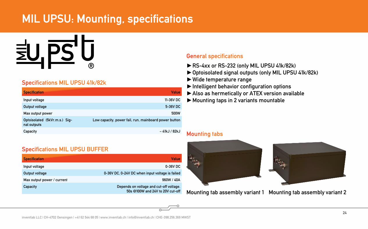
MIL UPSU: Mounting, specifications
® RS-4xx or RS-232 (only MIL UPSU 41k/82k) Optoisolated signal outputs (only MIL UPSU 41k/82k) Wide temperature range Intelligent behavior configuration options Also as hermetically or ATEX version available Mounting taps in 2 variants mountable
Specification Value
Input voltage 11-36V DC
Output voltage 5-36V DC
Max output power 500W
Optoisolated (5kVr.m.s.) Sig-nal outputs
Low capacity, power fail, run, mainboard power button
Capacity ~ 41kJ / 82kJ
Specifications MIL UPSU 41k/82k
Mounting tab assembly variant 1 Mounting tab assembly variant 2
General specifications
Mounting tabs
Specification Value
Input voltage 0-36V DC
Output voltage 0-36V DC, 0-24V DC when input voltage is failed
Max output power / current 960W / 40A
Capacity Depends on voltage and cut-off voltage.50s @100W and 24V to 20V cut-off
Specifications MIL UPSU BUFFER
inventlab LLC | CH-4702 Oensingen | +41 62 544 68 05 | www.inventlab.ch | [email protected] | CHE-398.256.369 MWST25
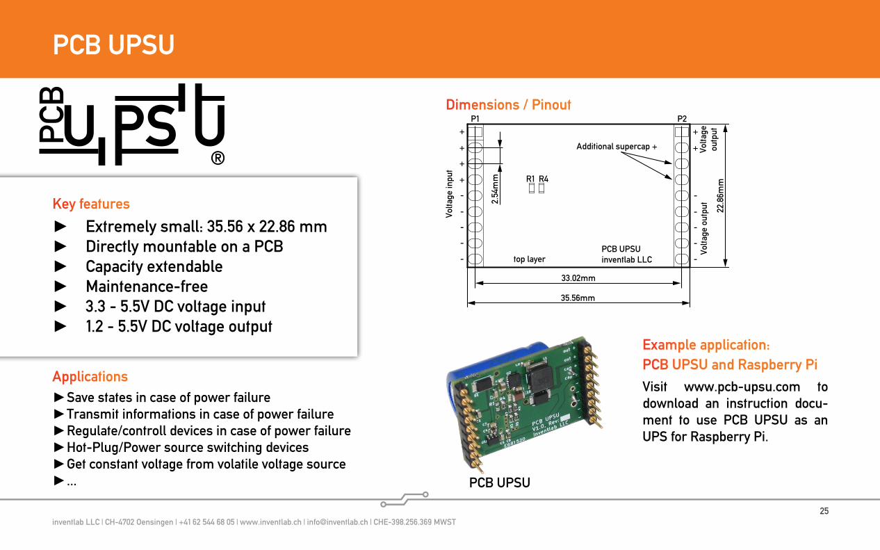
PCB UPSU
Save states in case of power failure Transmit informations in case of power failure Regulate/controll devices in case of power failure Hot-Plug/Power source switching devices Get constant voltage from volatile voltage source ...
Applications
Extremely small: 35.56 x 22.86 mm Directly mountable on a PCB Capacity extendable Maintenance-free 3.3 - 5.5V DC voltage input 1.2 - 5.5V DC voltage output
Key features
®
PCB UPSU
P2P1
PCB UPSUinventlab LLC
R4R1
35.56mm
22.8
6mm
33.02mm
2.54
mm
Volta
ge in
put
+
+
+
+
-
-
-
-
-
+
+
-
-
-
-
-
Volta
ge o
utpu
t
Additional supercap +
top layer
Volta
geou
tput
Dimensions / Pinout
Example application:PCB UPSU and Raspberry Pi
Visit www.pcb-upsu.com to download an instruction docu-ment to use PCB UPSU as an UPS for Raspberry Pi.

inventlab LLC | CH-4702 Oensingen | +41 62 544 68 05 | www.inventlab.ch | [email protected] | CHE-398.256.369 MWST26
inventlab integration modules
Standard products to build almost every powering application
Cost-effective solutions, even for applica- tions, which requires only one pcs
Design support from inventlab minimizes engineering risk and reduces evaluation effort
Configurable and wide voltage ranges Extended temperature ranges
Key features
Buffer to provide high currents UPS solutions Load sharing Redundant power supplies Undervoltage protection Current senging ...
Applications
inventlab integration modulesinventlab integration modules closes the gap between not suitab-le standard products and too expensive engineering for a suitable specific solution. With inventlab integration modules, applications are rapidly realizable in a modular construction.Especially ultracapacitor based solutions are often special and non-standard solutions, which require high-current modules in wide voltage ranges. This modules needs to be operate properly down to 0V without having to enter an undefined state. inventlab modules are build with respect to this aspects.
Ultracapacitor calculatorDimensioning and evaluating ultracapacitor based on power and energy requirements can be a very iterative process.Use our online calculator:https://www.inventlab.ch/ultra-capacitor_energy_calculator/

inventlab LLC | CH-4702 Oensingen | +41 62 544 68 05 | www.inventlab.ch | [email protected] | CHE-398.256.369 MWST27
iub - inventlab ultracapacitor buffer
Low-Cost, High-Power UPS solution 3.6 to 36 V (12.5V buffer voltage) Parallelable to increase capacity Serializable to increase UPS voltage Currents up to 40A Integrated power path controller Power path with MOSFETs Wide operating temperature -40 to +65°C
Key features
iub
inventlab LLC | CH-4702 Oensingen | +41 62 544 68 05 | www.inventlab.ch | [email protected] | CHE-398.256.369 MWST28
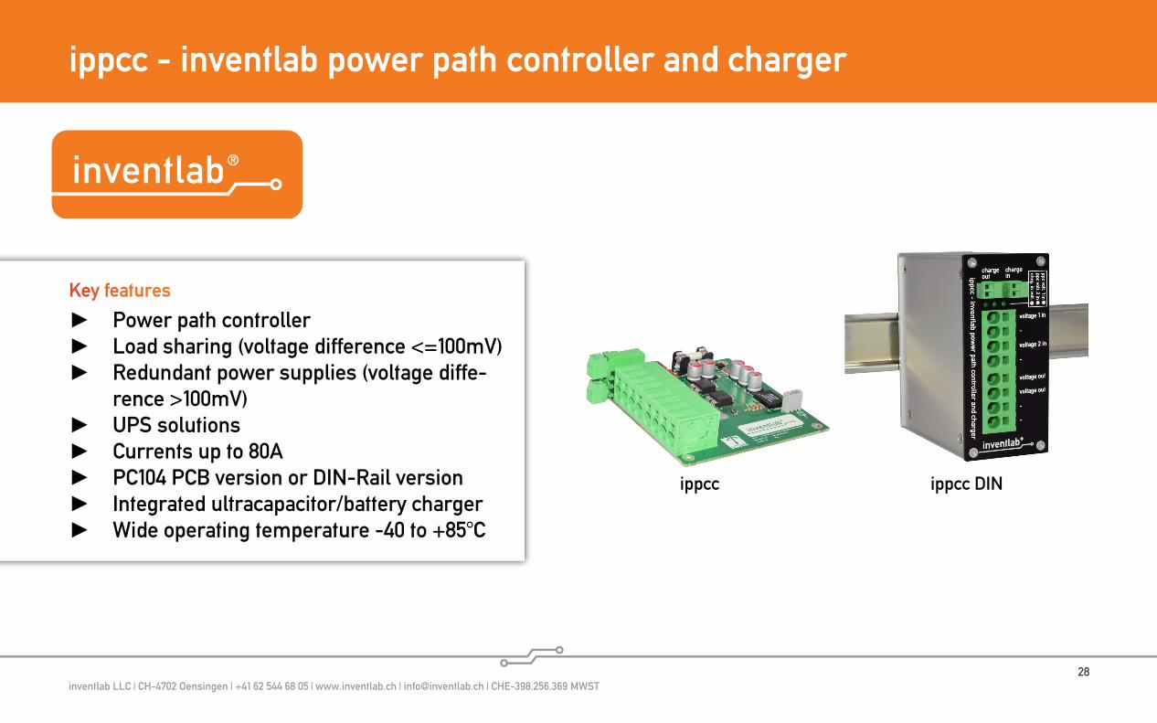
ippcc - inventlab power path controller and charger
Power path controller Load sharing (voltage difference <=100mV) Redundant power supplies (voltage diffe-
rence >100mV) UPS solutions Currents up to 80A PC104 PCB version or DIN-Rail version Integrated ultracapacitor/battery charger Wide operating temperature -40 to +85°C
Key features
ippcc ippcc DIN
inventlab LLC | CH-4702 Oensingen | +41 62 544 68 05 | www.inventlab.ch | [email protected] | CHE-398.256.369 MWST29
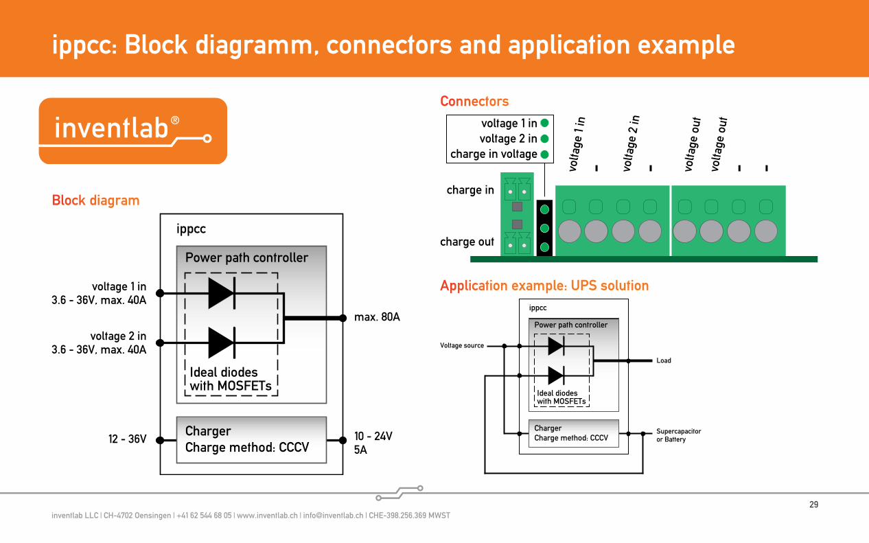
ippcc: Block diagramm, connectors and application example
12 - 36V 10 - 24V5A
voltage 1 in3.6 - 36V, max. 40A
voltage 2 in3.6 - 36V, max. 40A
Power path controller
Ideal diodeswith MOSFETs
max. 80A
ippcc
ChargerCharge method: CCCV
voltage 1 involtage 2 in
charge in voltage
volta
ge 1
in- vo
ltage
2 in
- volta
ge o
utvo
ltage
out
- -
charge in
charge out
Supercapacitoror Battery
Power path controller
Ideal diodeswith MOSFETs
ippcc
ChargerCharge method: CCCV
Voltage source
Load
Block diagram
Connectors
Application example: UPS solution

inventlab LLC | CH-4702 Oensingen | +41 62 544 68 05 | www.inventlab.ch | [email protected] | CHE-398.256.369 MWST30
ist - inventlab schmitt trigger module
Schmitt trigger module Adjustable switch on and off threshold Wide operating voltage 7 - 40V DC Can also be powered by AC: 5 - 28V AC Proper state down to 0V 80A PFET output Relais output Dimensions: 50 x 60 mm Wide operating temperature -40 to +85°C
Key features
ist - inventlab schmitt trigger module
inventlab LLC | CH-4702 Oensingen | +41 62 544 68 05 | www.inventlab.ch | [email protected] | CHE-398.256.369 MWST31
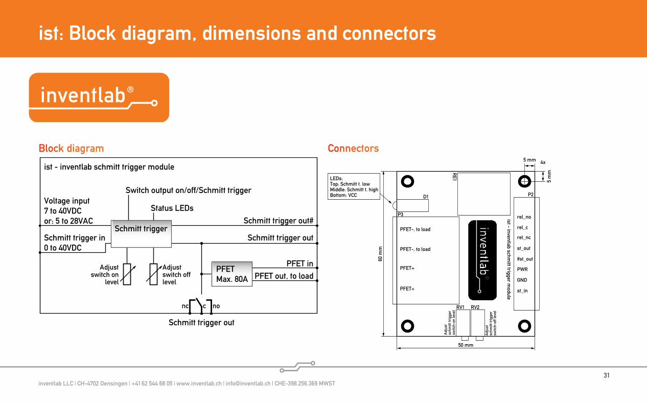
ist: Block diagram, dimensions and connectors
60 m
m
50 mm
5 m
m
5 mm 4x
LEDs:Top: Schmitt t. lowMiddle: Schmitt t. highBottom: VCC
ist - inventlab schmitt trigger m
odule
Adj
ust
schm
itt tr
igge
rsw
itch-
on le
vel
Adj
ust
schm
itt tr
igge
rsw
itch-
off l
evel
D1
RV1 RV2
P3
P2
PFET-, to load
PFET+
PFET-, to load
PFET+
rel_no
rel_c
rel_nc
st_out
#st_out
PWR
GND
st_in
RE1
Block diagram
Schmitt trigger in0 to 40VDC
Schmitt trigger out
Status LEDs
ist - inventlab schmitt trigger module
Voltage input7 to 40VDCor: 5 to 28VAC Schmitt trigger out#
nonc c
PFET inPFET out, to load
Adjustswitch on
level
Adjustswitch offlevel
Switch output on/off/Schmitt trigger
Schmitt trigger outSchmitt trigger
PFETMax. 80A
Connectors
inventlab LLC | CH-4702 Oensingen | +41 62 544 68 05 | www.inventlab.ch | [email protected] | CHE-398.256.369 MWST32
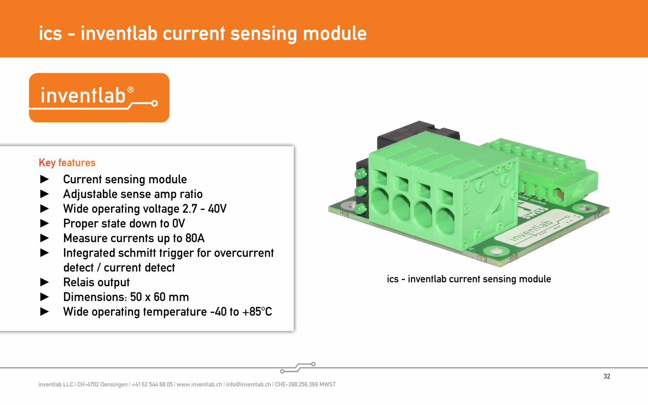
ics - inventlab current sensing module
Current sensing module Adjustable sense amp ratio Wide operating voltage 2.7 - 40V Proper state down to 0V Measure currents up to 80A Integrated schmitt trigger for overcurrent
detect / current detect Relais output Dimensions: 50 x 60 mm Wide operating temperature -40 to +85°C
Key features
ics - inventlab current sensing module
inventlab LLC | CH-4702 Oensingen | +41 62 544 68 05 | www.inventlab.ch | [email protected] | CHE-398.256.369 MWST33
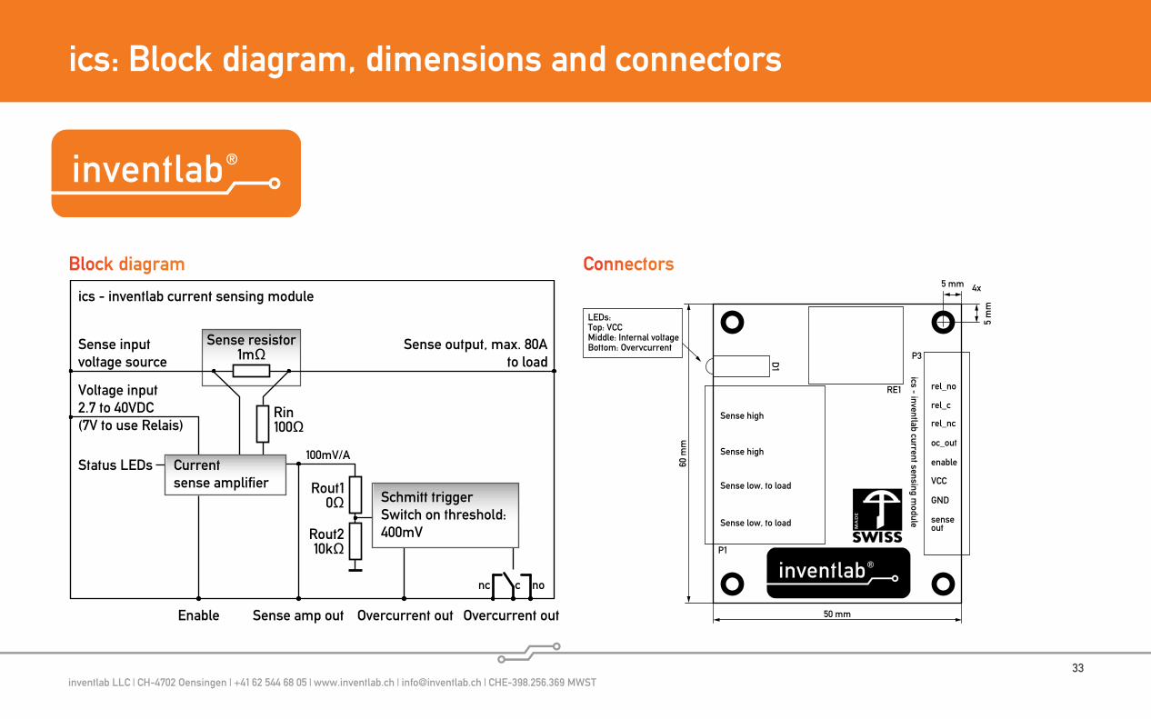
ics: Block diagram, dimensions and connectors
Block diagram Connectors
ics - inventlab current sensing module
P3
RE1
D1
P1
Sense high
Sense low, to load
Sense high
Sense low, to load
rel_no
rel_c
rel_nc
oc_out
enable
VCC
GND
sense out
60 m
m
50 mm
5 m
m
5 mm 4x
LEDs:Top: VCCMiddle: Internal voltageBottom: OvervcurrentSense input
voltage source
Enable Overcurrent out
Status LEDs
Sense output, max. 80Ato load
Sense resistor1mΩ
ics - inventlab current sensing module
Voltage input2.7 to 40VDC (7V to use Relais)
Sense amp out
Rin100Ω
Rout10Ω
Rout210kΩ
Overcurrent out
Schmitt triggerSwitch on threshold:400mV
nonc c
100mV/ACurrentsense amplifier

inventlab LLC | CH-4702 Oensingen | +41 62 544 68 05 | www.inventlab.ch | [email protected] | CHE-398.256.369 MWST34
More informations / Your project / Where to buy
See product websites: http://www.10a-upsu.com http://www.atx-upsu.com http://www.20w-upsu.com http://www.pc104-upsu.com http://www.mil-upsu.com http://www.pcb-upsu.com http://www.inventlab.ch
Your special requirements
Please contact inventlab LLC if your project has special require-ments. Our engineers look forward to hearing from you.
https://shop.inventlab.ch
More informations, datasheets, 3D models
Where to buy
inventlab LLCSolothurnstrasse 6CH-4702 Oensingen+41 62 544 68 [email protected]
Manufacturer
inventlab®, CHYPSOTECH®, ElektronikEntwicklung.ch®, ATX UPSU®, 20W UPSU®, MIL UPSU®, PC104 UPSU®, Das Zuhause der Technik.® and ercotima® are registered trademarks of in-ventlab LLC, all other brand names, trademarks and registered trademarks are property of their respective owners.
Ultracapacitor calculator
https://www.inventlab.ch/ultracapacitor_energy_calculator/