pnoz m b0 en - Компания ТЕХНО LIFE · Pilz GmbH & Co. KG, ... 6.2.2.2 Load project via...
47
Operating Manual — No. 1002660-EN-01 Configurable Control System PNOZmulti Operating Manual PNOZ m B0 Operating Manual PNOZ m B0 PNOZ m B0
Transcript of pnoz m b0 en - Компания ТЕХНО LIFE · Pilz GmbH & Co. KG, ... 6.2.2.2 Load project via...
Operating Manual — No. 1002660-EN-01
Configurable Control System PNOZmulti
Operating Manual PNOZ m B0
Operating Manual PNOZ m B0
PNOZ m B0
��������� ���������� ������ ������������� ������� ��
����������������������� ����� ��������������������������������������� �������������������� ��� ��� � �����
!������� ��� ������ ��������� ���� ����������� ����� �"�������������������������
����#$��%�#$��&%#$��'()#$������#$��!*'#$��!!#$��+%!#$�!�����,-!� #$�!�����*.*#$!�����'*�� #$������ ��������������#����������������� �� ����������������/������������������������ ������� ������
!0���� ��!����0�������
Preface
Contents
Contents
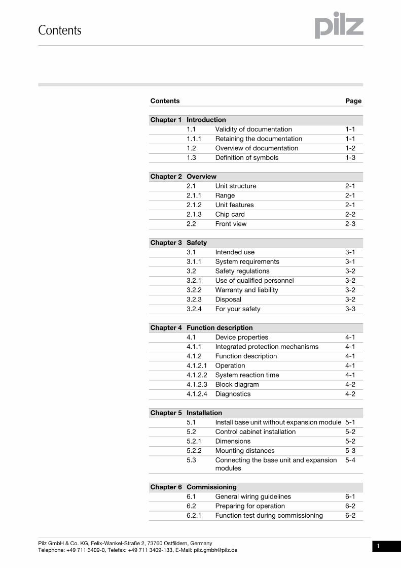
Contents Page
Chapter 1 Introduction1.1 Validity of documentation 1-11.1.1 Retaining the documentation 1-11.2 Overview of documentation 1-21.3 Definition of symbols 1-3
Chapter 2 Overview2.1 Unit structure 2-12.1.1 Range 2-12.1.2 Unit features 2-12.1.3 Chip card 2-22.2 Front view 2-3
Chapter 3 Safety3.1 Intended use 3-13.1.1 System requirements 3-13.2 Safety regulations 3-23.2.1 Use of qualified personnel 3-23.2.2 Warranty and liability 3-23.2.3 Disposal 3-23.2.4 For your safety 3-3
Chapter 4 Function description4.1 Device properties 4-14.1.1 Integrated protection mechanisms 4-14.1.2 Function description 4-14.1.2.1 Operation 4-14.1.2.2 System reaction time 4-14.1.2.3 Block diagram 4-24.1.2.4 Diagnostics 4-2
Chapter 5 Installation5.1 Install base unit without expansion module 5-15.2 Control cabinet installation 5-25.2.1 Dimensions 5-25.2.2 Mounting distances 5-35.3 Connecting the base unit and expansion
modules5-4
Chapter 6 Commissioning6.1 General wiring guidelines 6-16.2 Preparing for operation 6-26.2.1 Function test during commissioning 6-2
Pilz GmbH & Co. KG, Felix-Wankel-Straße 2, 73760 Ostfildern, GermanyTelephone: +49 711 3409-0, Telefax: +49 711 3409-133, E-Mail: [email protected]
1
Contents
2
6.2.2 Commissioning the control system 6-26.2.2.1 Load project from chip card 6-36.2.2.2 Load project via USB port 6-36.2.3 Connection 6-46.2.4 Using the chip card 6-76.3 Connection example 6-8
Chapter 7 Operation7.1 Rotary knob 7-17.1.1 Function 7-17.1.2 Pull out and retract the knob 7-17.1.3 Rotate and press the knob 7-17.2 Messages 7-27.2.1 Display elements 7-27.2.1.1 Status indicators 7-27.2.1.2 Display 7-3
Chapter 8 Technical Details8.1 Technical details 8-18.2 Maximum capacitive load C (μF) with load
current I (A) at the semiconductor outputs8-4
8.3 Maximum permitted total current of the semiconductor outputs
8-5
8.4 Maximum permitted humidity 8-68.4.1 Max. relative humidity, operation 8-68.4.2 Max. relative humidity, storage 8-68.5 Order reference 8-7
Pilz GmbH & Co. KG, Felix-Wankel-Straße 2, 73760 Ostfildern, GermanyTelephone: +49 711 3409-0, Telefax: +49 711 3409-133, E-Mail: [email protected]
1.1 Validity of documentation
1 Introduction
11000IntroductionIntroduction1-1.1Validity of documentation1100Validity of documentation1-Einf Gltigkeit der Dokumentation
This documentation is valid for the product PNOZ m B0. It is valid until new documentation is published.
Einf Einleitung
This operating manual explains the function and operation, describes the installation and provides guidelines on how to connect the product.
1.1.1 Retaining the documentationRetaining the documentation1-Einf Aufbewahren
This documentation is intended for instruction and should be retained for future reference.
Pilz GmbH & Co. KG, Felix-Wankel-Straße 2, 73760 Ostfildern, GermanyTelephone: +49 711 3409-0, Telefax: +49 711 3409-133, E-Mail: [email protected]
1-1
1.2 Overview of documentation
1 Introduction
1-2
1.2Overview of documentation1200Overview of documentation1-Einf_Uebersicht_über_die_Doku_6_Inbetriebnahme
1 Introduction
The introduction is designed to familiarise you with the contents, struc-ture and specific order of this manual.
2 Overview
This chapter provides information on the product's most important fea-tures.
3 Safety
This chapter must be read as it contains important information on in-tended use.
4 Function Description
This chapter describes the product's mode of operation.
5 Installation
This chapter explains how to install the product.
6 Commissioning
This chapter describes the product's commissioning and wiring.
7 Operation
This chapter describes how to operate the product and gives tips in the case of a fault.
8 Technical Details
This chapter contains the product's technical details and order refer-ence.
Pilz GmbH & Co. KG, Felix-Wankel-Straße 2, 73760 Ostfildern, GermanyTelephone: +49 711 3409-0, Telefax: +49 711 3409-133, E-Mail: [email protected]
1.3 Definition of symbols
1 Introduction
1.3Definition of symbols1300Definition of symbols1-Einfhrung Zeichen
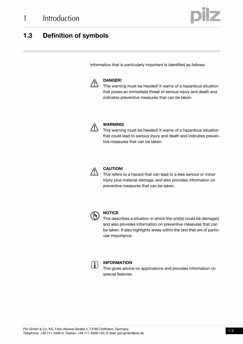
Information that is particularly important is identified as follows:
DANGER!This warning must be heeded! It warns of a hazardous situation that poses an immediate threat of serious injury and death and indicates preventive measures that can be taken.
WARNING!This warning must be heeded! It warns of a hazardous situation that could lead to serious injury and death and indicates preven-tive measures that can be taken.
CAUTION!This refers to a hazard that can lead to a less serious or minor injury plus material damage, and also provides information on preventive measures that can be taken.
NOTICEThis describes a situation in which the unit(s) could be damaged and also provides information on preventive measures that can be taken. It also highlights areas within the text that are of partic-ular importance.
INFORMATIONThis gives advice on applications and provides information on special features.
Pilz GmbH & Co. KG, Felix-Wankel-Straße 2, 73760 Ostfildern, GermanyTelephone: +49 711 3409-0, Telefax: +49 711 3409-133, E-Mail: [email protected]
1-3
1 Introduction
1-4
Pilz GmbH & Co. KG, Felix-Wankel-Straße 2, 73760 Ostfildern, GermanyTelephone: +49 711 3409-0, Telefax: +49 711 3409-133, E-Mail: [email protected]
2.1 Unit structure
2 Overview
22000OverviewOverview2-2.1Unit structure2100Unit structure2-2.1.1 RangeRange2-Lieferumfang_Multi2
Base unit PNOZ m B0 Terminator Documentation on data medium
2.1.2 Unit featuresUnit features2-Gerätemerkmale_Verwendung
Using the product PNOZ m B0:Verwendung/Bildunterschrift_multi_2_Basis
Base unit from the configurable control system PNOZmulti 2Geraetemerkmale_Zusatz BA Einleitung
The product has the following features:Gertemerkmale_multi_2_Basis
Can be configured in the PNOZmulti Configurator Semiconductor outputs:
4 safety outputs Depending on the application, up to PL e of EN ISO 13849-1 and up to SIL CL 3 of EN IEC 62061
12 inputs for connecting, for example:– Emergency stop pushbuttons– Two-hand pushbuttons– Safety gate limit switches– Reset buttons– Light beam devices– Scanners– Enabling switches– PSEN– Operating mode selector switches
8 configurable inputs/outputsCan be configured as:
– Inputs (see above for connection options)or
– Auxiliary outputs 4 configurable outputs
Can be configured as:– Auxiliary outputsor
– Test pulse outputs LED for:
– Error messages– Diagnostics– Supply voltage– Fault at the outputs– Fault at the inputs
Pilz GmbH & Co. KG, Felix-Wankel-Straße 2, 73760 Ostfildern, GermanyTelephone: +49 711 3409-0, Telefax: +49 711 3409-133, E-Mail: [email protected]
2-1
2.1 Unit structure
2 Overview
2-2
Backlit display for:– Error messages– State of supply voltage– State of inputs/outputs– Status information– Device information
Test pulse outputs used to monitor shorts across the inputs Monitoring of shorts between the safety outputs Plug-in connection terminals:
Either spring-loaded terminal or screw terminal available as an acces-sory (see order reference)
Rotary knob for menu controlGerätemerkmal_multi_Mini_Basis_Anschluss_Erweiterung
Expansion modules can be connected(please refer to the document "PNOZmulti System Expansion" for de-tails of the type and number that can be connected)
2.1.3 Chip cardChip card2-Bestimmung/Gertebeschreibung_multi_Chipkarte
To be able to use the product you will need a chip card.
Chip cards are available with memories of 8 kByte and 32 kByte. For large-scale projects we recommend the 32 kByte chip card (see Tech-nical Catalogue). Accessories chapter).
Pilz GmbH & Co. KG, Felix-Wankel-Straße 2, 73760 Ostfildern, GermanyTelephone: +49 711 3409-0, Telefax: +49 711 3409-133, E-Mail: [email protected]
2.2 Front view
2 Overview
2.2Front view2200Front view2-Klemmenbelegung PNOZ mm0.1p
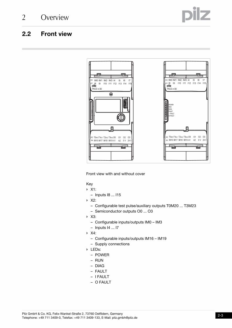
Front view with and without coverLegende__Klemmenbelegung_mini_multi_Basis_BA
Key X1:
– Inputs I8 ... I15 X2:
– Configurable test pulse/auxiliary outputs T0M20 ... T3M23– Semiconductor outputs O0 ... O3
X3:– Configurable inputs/outputs IM0 – IM3– Inputs I4 ... I7
X4:– Configurable inputs/outputs IM16 – IM19– Supply connections
LEDs:– POWER– RUN– DIAG– FAULT– I FAULT– O FAULT
��
��
��
��
��������
�� ��� ��� �������� ��� �� �� ������������ ���
��
��
��
��
��������
� � ����� � ���� ���� ���� ���������� ����
�� ��� ��� ��
�� ��� ��� �������� ��� �� �� ������������ ���
� � ����� � ���� ���� ���� ���������� ����
�� ��� ��� ��
Pilz GmbH & Co. KG, Felix-Wankel-Straße 2, 73760 Ostfildern, GermanyTelephone: +49 711 3409-0, Telefax: +49 711 3409-133, E-Mail: [email protected]
2-3
2 Overview
2-4
Pilz GmbH & Co. KG, Felix-Wankel-Straße 2, 73760 Ostfildern, GermanyTelephone: +49 711 3409-0, Telefax: +49 711 3409-133, E-Mail: [email protected]
3.1 Intended use
3 Safety
33000SafetySafety3-3.1Intended use3100Intended use3-Bestimmung/Gertebeschreibung_multi_System_2
The configurable control system PNOZmulti 2 is used for the safety-re-lated interruption of safety circuits and is designed for use in: E-STOP equipment Safety circuits in accordance with VDE 0113 Part 1 and EN 60204-1
Bestimmung/Gertebeschreibung_multi_Zusatz_Achtung_Standard-Ausgaenge_BA
Bestimmung/Gerätebeschreibung_EMV+Ausschluss
Intended use includes making the electrical installation EMC-compliant. The product is designed for use in an industrial environment. It is not suitable for use in a domestic environment, as this can lead to interfer-ence.
The following is deemed improper use in particular: Any component, technical or electrical modification to the product Use of the product outside the areas described in this manual Use of the product outside the technical details (see chapter entitled
“Technical Details”)
3.1.1 System requirementsSystem requirements3-Systemvoraussetzungen - Verweis auf Produktänderungen
Please refer to the "Product Modifications" document in the "Version overview" section for details of which versions of the base unit and PNOZmulti Configurator can be used for this product.
CAUTION!Inputs and outputs for standard functions must not be used for safety-related applications.
Pilz GmbH & Co. KG, Felix-Wankel-Straße 2, 73760 Ostfildern, GermanyTelephone: +49 711 3409-0, Telefax: +49 711 3409-133, E-Mail: [email protected]
3-1
3.2 Safety regulations
3 Safety
3-2
3.2Safety regulations3200Safety regulations3-3.2.1 Use of qualified personnelUse of qualified personnel3-Sich Qualif. Personal
The products may only be assembled, installed, programmed, commis-sioned, operated, maintained and decommissioned by competent per-sons.
A competent person is someone who, because of their training, experi-ence and current professional activity, has the specialist knowledge re-quired to test, assess and operate the work equipment, devices, systems, plant and machinery in accordance with the general standards and guidelines for safety technology.
It is the company's responsibility only to employ personnel who: Are familiar with the basic regulations concerning health and safety /
accident prevention Have read and understood the safety guidelines given in this descrip-
tion Have a good knowledge of the generic and specialist standards ap-
plicable to the specific application.
3.2.2 Warranty and liabilityWarranty and liability3-Sich Gewhrleistung
All claims to warranty and liability will be rendered invalid if: The product was used contrary to the purpose for which it is intended Damage can be attributed to not having followed the guidelines in the
manual Operating personnel are not suitably qualified Any type of modification has been made (e.g. exchanging compo-
nents on the PCB boards, soldering work etc.).
3.2.3 DisposalDisposal3-Sich Entsorgung
In safety-related applications, please comply with the mission time tM
in the safety-related characteristic data. When decommissioning, please comply with local regulations regard-
ing the disposal of electronic devices (e.g. Electrical and Electronic Equipment Act).
Pilz GmbH & Co. KG, Felix-Wankel-Straße 2, 73760 Ostfildern, GermanyTelephone: +49 711 3409-0, Telefax: +49 711 3409-133, E-Mail: [email protected]

3.2 Safety regulations
3 Safety
3.2.4 For your safetyFor your safety3-Zu Ihrer Sicherheit_mini_multi_Basis
The unit meets all the necessary conditions for safe operation. However, you should always ensure that the following safety requirements are met: Adequate protection must be provided for all inductive consumers. Do not open the housing or make any unauthorised modifications. Please make sure you shut down the supply voltage when performing
maintenance work (e.g. exchanging contactors).
Pilz GmbH & Co. KG, Felix-Wankel-Straße 2, 73760 Ostfildern, GermanyTelephone: +49 711 3409-0, Telefax: +49 711 3409-133, E-Mail: [email protected]
3-3
3 Safety
3-4
Pilz GmbH & Co. KG, Felix-Wankel-Straße 2, 73760 Ostfildern, GermanyTelephone: +49 711 3409-0, Telefax: +49 711 3409-133, E-Mail: [email protected]
4.1 Device properties
4 Function description
44000Function descriptionFunction description4-4.1Device properties4100Device properties4-4.1.1 Integrated protection mechanismsIntegrated protection mechanisms4-Sicherheitseigenschaften_multi_allgemein
The relay conforms to the following safety criteria: The circuit is redundant with built-in self-monitoring. The safety function remains effective in the case of a component fail-
ure. Sicherheitseigenschaften_Halbleiter
The safety outputs are tested periodically using a disconnection test.
4.1.2 Function descriptionFunction description4-
4.1.2.1 OperationOperation4-Funktionen_multi_Basis
The function of the inputs and outputs on the control system depends on the safety circuit created using the PNOZmulti Configurator. A chip card is used to download the safety circuit to the base unit. The base unit has 2 microcontrollers that monitor each other. They evaluate the in-put circuits on the base unit and expansion modules and switch the out-puts on the base unit and expansion modules accordingly.
The LEDs on the base unit and expansion modules indicate the status of the configurable control system PNOZmulti.
The online help on the PNOZmulti Configurator contains descriptions of the operating modes and all the functions of the control system, plus connection examples.
4.1.2.2 System reaction timeSystem reaction time4-_Dummy-Vorlage
The maximum reaction time between an input switching off and a linked semiconductor output in the system switching off is 39 ms. If other times are configured within the user program, switch-off may be delayed further.
Pilz GmbH & Co. KG, Felix-Wankel-Straße 2, 73760 Ostfildern, GermanyTelephone: +49 711 3409-0, Telefax: +49 711 3409-133, E-Mail: [email protected]
4-1
4.1 Device properties
4 Function description
4-2
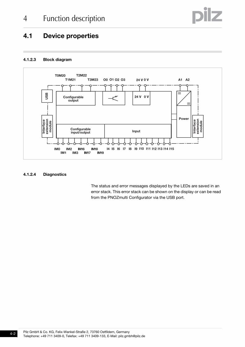
4.1.2.3 Block diagramBlock diagram4-Blockschaltbild PNOZ mm0.1p
4.1.2.4 DiagnosticsDiagnostics4-Funktionen_mini_multi_Basis_Diagnose
The status and error messages displayed by the LEDs are saved in an error stack. This error stack can be shown on the display or can be read from the PNOZmulti Configurator via the USB port.
�
�����
�� �
�
�� �
������ ������ �� �
���������
��� ������� ��� �� ��
���� ��� � �� �� ��!" �����
����" ���
��! ��
������#
��$���%
���
&�' ��
()*
������#
��$���%
���
&�' ��
������ �������� �+� �� �
������
����
Pilz GmbH & Co. KG, Felix-Wankel-Straße 2, 73760 Ostfildern, GermanyTelephone: +49 711 3409-0, Telefax: +49 711 3409-133, E-Mail: [email protected]
5.1 Install base unit without expansion module
5 Installation
55000InstallationInstallation5-5.1Install base unit without expansion module 5100Install base unit without expansion module 5-Montage_multi_2_ohne_Modul_BA
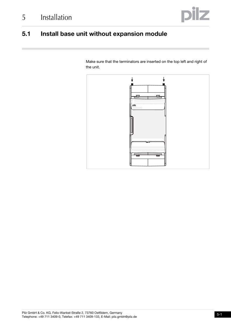
Make sure that the terminators are inserted on the top left and right of the unit.
�� ��� ��� �������� ��� �� �� ������������ ���
��
��
��
��
����������
� � ����� � ���� ���� ���� ���������� ����
�� ��� ��� ��
Pilz GmbH & Co. KG, Felix-Wankel-Straße 2, 73760 Ostfildern, GermanyTelephone: +49 711 3409-0, Telefax: +49 711 3409-133, E-Mail: [email protected]
5-1
5.2 Control cabinet installation
5 Installation
5-2
5.2Control cabinet installation5200Control cabinet installation5-Montage_multi_2_allgemein
The unit should be installed in a control cabinet with a protection type of at least IP54.
Fit the safety system to a horizontal mounting rail. The venting slots must face upward and downward. Other mounting positions could destroy the safety system.
Use the locking slide on the rear of the unit to attach it to a mounting rail.
In environments exposed to heavy vibration, the unit should be se-cured using a fixing element (e.g. retaining bracket or end angle).
Open the locking slide before lifting the unit from the mounting rail. To comply with EMC requirements, the mounting rail must have a low
impedance connection to the control cabinet housing.Montage_EMV ESD
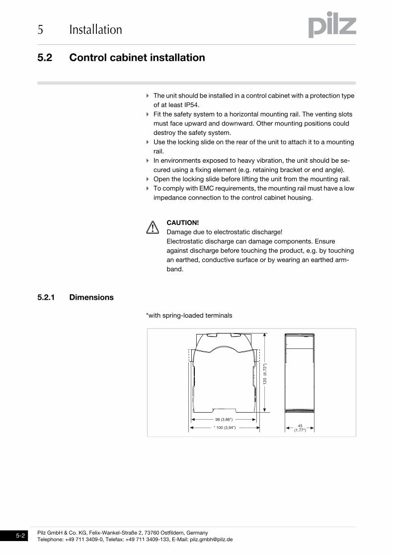
5.2.1 DimensionsDimensions5-Abmessungen PNOZ m B0
*with spring-loaded terminals
CAUTION!Damage due to electrostatic discharge!Electrostatic discharge can damage components. Ensure against discharge before touching the product, e.g. by touching an earthed, conductive surface or by wearing an earthed arm-band.
Pilz GmbH & Co. KG, Felix-Wankel-Straße 2, 73760 Ostfildern, GermanyTelephone: +49 711 3409-0, Telefax: +49 711 3409-133, E-Mail: [email protected]
5.2 Control cabinet installation
5 Installation
5.2.2 Mounting distancesMounting distances5-][Montage_multi_Montageabstaende
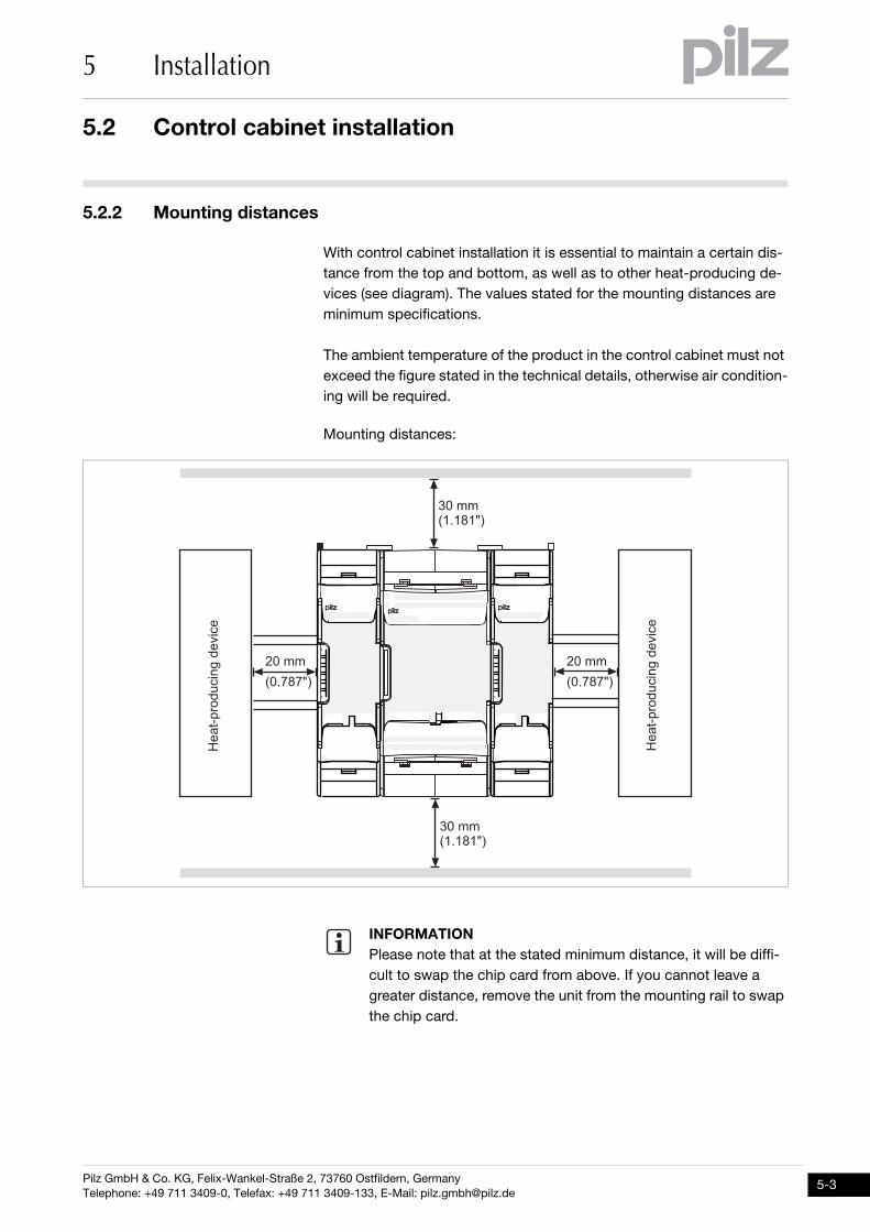
With control cabinet installation it is essential to maintain a certain dis-tance from the top and bottom, as well as to other heat-producing de-vices (see diagram). The values stated for the mounting distances are minimum specifications.
The ambient temperature of the product in the control cabinet must not exceed the figure stated in the technical details, otherwise air condition-ing will be required.
Mounting distances:
][Montage_multi_Montageabstaende_chipkarte
INFORMATIONPlease note that at the stated minimum distance, it will be diffi-cult to swap the chip card from above. If you cannot leave a greater distance, remove the unit from the mounting rail to swap the chip card.
�������� ���
�������� ���
����
��� ���
����
��� ���
�� ��� ��� �������� ��� �� ������������ ���
��
��
��
��
����������
� � ����� � ���� ���� ���� ���������� ����
�� ��� ��� ��
���
����
����
!"�
��#
��
���
����
����
!"�
��#
��
Pilz GmbH & Co. KG, Felix-Wankel-Straße 2, 73760 Ostfildern, GermanyTelephone: +49 711 3409-0, Telefax: +49 711 3409-133, E-Mail: [email protected]
5-3
5.3 Connecting the base unit and expansion modules
5 Installation
5-4
5.3Connecting the base unit and expansion modules5300Connecting the base unit and expansion modules5-Montage_multi_Basis_Verweis_Systemausbau
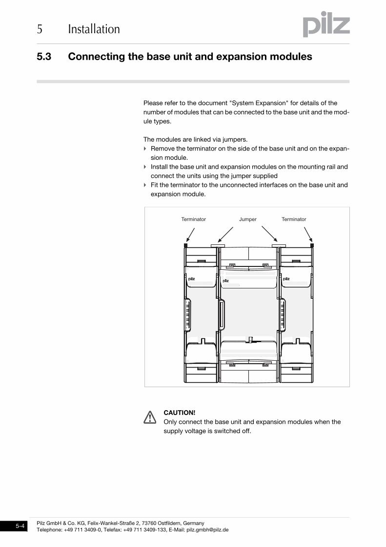
Please refer to the document "System Expansion" for details of the number of modules that can be connected to the base unit and the mod-ule types.
Montage_multi_2_verbind_mit_Modul_BA
The modules are linked via jumpers. Remove the terminator on the side of the base unit and on the expan-
sion module. Install the base unit and expansion modules on the mounting rail and
connect the units using the jumper supplied Fit the terminator to the unconnected interfaces on the base unit and
expansion module.
Verdrahtung_multi_Achtung_Kabel_spannungsl_ziehen_Basis_u_Modul
CAUTION!Only connect the base unit and expansion modules when the supply voltage is switched off.
�������� ��������
�� ��� ��� �������� ��� �� ������������ ���
��
��
��
��
����������
� � ����� � ���� ���� ���� ���������� ����
�� ��� ��� ��
��� ��
Pilz GmbH & Co. KG, Felix-Wankel-Straße 2, 73760 Ostfildern, GermanyTelephone: +49 711 3409-0, Telefax: +49 711 3409-133, E-Mail: [email protected]
6.1 General wiring guidelines
6 Commissioning
66000CommissioningCommissioning6-6.1General wiring guidelines6100General wiring guidelines6-Verdrahtung_mini_multi_HL_Ausg
The wiring is defined in the circuit diagram in the Configurator. There you can select the inputs that are to perform a safety function and the out-puts that are to switch this safety function.
Note: Information given in the "Technical details" must be followed. Outputs O0 to O3 are semiconductor outputs Use copper wire that can withstand 75°C. Sufficient fuse protection must be provided on all output contacts
with inductive loads. The safety system and input circuits must always be supplied by a
single power supply. The power supply must meet the regulations for extra low voltages with safe separation.
Test pulse outputs must exclusively be used to test the inputs. They must not be used to drive loads. Do not route the test pulse lines together with actuator cables within an unprotected multicore cable.
Pilz GmbH & Co. KG, Felix-Wankel-Straße 2, 73760 Ostfildern, GermanyTelephone: +49 711 3409-0, Telefax: +49 711 3409-133, E-Mail: [email protected]
6-1
6.2 Preparing for operation
6 Commissioning
6-2
6.2Preparing for operation6200Preparing for operation6-6.2.1 Function test during commissioningFunction test during commissioning6-Verdrahtung_multi_Basis_Betr_Funktionstest_BA
6.2.2 Commissioning the control systemCommissioning the control system6-Verdrahtung_multi_Basis_Betr_erstes_Mal_mini_multi_BA
Procedure: Wire the inputs and outputs on the base unit in accordance with the
circuit diagram. Connect the supply voltage:
– Supply voltage for the control system:– Terminal A1: + 24 VDC– Terminal A2: 0 V– Supply voltage for the semiconductor outputs:– 24 V terminal: + 24 VDC– 0V terminal: 0 V
Please note: The supply voltage for the semiconductor outputs must al-ways be present, even if you are not using the semiconductor outputs.
Verdrahtung_multi_Basis_Betr_erstes_Mal_galvanische Trennung_BA
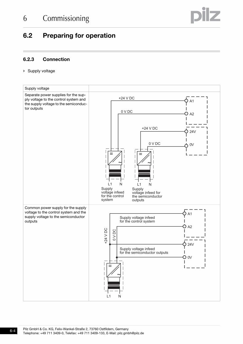
When the voltages are fed separately using two power supplies, the supply voltage for the control system and the supply voltage for the semiconductor outputs are galvanically isolated.
Verdrahtung_multi_Basis_Betr_Erweiterungsmodule nicht abstecken während Betrieb_BA
CAUTION!It is essential to check that the safety devices operate correctly after the chip card has been exchanged after a project has been downloaded when the project has been deleted from the base unit's mem-
ory ("Reset Project" menu)
CAUTION!Do not connect or disconnect expansion modules and termina-tors during operation.
Pilz GmbH & Co. KG, Felix-Wankel-Straße 2, 73760 Ostfildern, GermanyTelephone: +49 711 3409-0, Telefax: +49 711 3409-133, E-Mail: [email protected]
6.2 Preparing for operation
6 Commissioning
6.2.2.1 Load project from chip cardLoad project from chip card6-Verdrahtung_mini_multi_Basis_Betr_erstes_Mal_von_Chipkarte_BA
Procedure: Insert the chip card containing the current project into the card slot on
the base unit. Switch on the supply voltage. The LC display shows the project
name, CRC sum and the date the project was created. Please check this information.
Load the project by pressing the rotary knob. For the project to be downloaded, the rotary knob must be held down for between 3 and 8 seconds. Once the project has been successfully downloaded, the status of the inputs and outputs will be shown on the display.
6.2.2.2 Load project via USB port Load project via USB port 6-Verdrahtung_mini_multi_Basis_Betr_erstes_Mal_USB_BA
Procedure: Insert a chip card into the card slot on the base unit. Connect the computer containing the PNOZmulti Configurator to the
base unit via the USB port. Switch on the supply voltage. Download the project (see PNOZmulti Configurator's online help). Once the project has been successfully downloaded, the status of the
inputs and outputs and the supply voltage will be shown on the dis-play. The "RUN" LED will be lit.
Pilz GmbH & Co. KG, Felix-Wankel-Straße 2, 73760 Ostfildern, GermanyTelephone: +49 711 3409-0, Telefax: +49 711 3409-133, E-Mail: [email protected]
6-3
6.2 Preparing for operation
6 Commissioning
6-4
6.2.3 ConnectionConnection6-Betriebsbereitschaft_herstellen_multi-2 Basisgerät
Supply voltage
Supply voltage
Separate power supplies for the sup-ply voltage to the control system and the supply voltage to the semiconduc-tor outputs
Common power supply for the supply voltage to the control system and the supply voltage to the semiconductor outputs
��������
������
�� �����������������������������
�� ������������������������������� ��
������
��������
�
�
!"
�
�
!"
#"
#�
���
��
��������
������
�
�
!"
#"
#�
���
��
�� �������������������������������
�� ��������������������������������� ��
Pilz GmbH & Co. KG, Felix-Wankel-Straße 2, 73760 Ostfildern, GermanyTelephone: +49 711 3409-0, Telefax: +49 711 3409-133, E-Mail: [email protected]
6.2 Preparing for operation
6 Commissioning
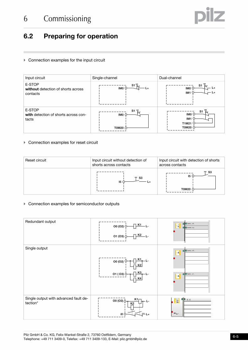
Connection examples for the input circuit
Connection examples for reset circuit
Connection examples for semiconductor outputs
Input circuit Single-channel Dual-channel
E-STOPwithout detection of shorts across contacts
E-STOPwith detection of shorts across con-tacts
Reset circuit Input circuit without detection of shorts across contacts
Input circuit with detection of shorts across contacts
Redundant output
Single output
Single output with advanced fault de-tection*
)��� ,-
)�
��
�� ,-
,-
��
����
)� )�
����
��
����
��
�)�
,-
�
����
)�
. ,/
���0�1
���0��1
.� ,/
.� ,/
.�
���0�1
���0���1
.� ,/
.
.�
,-
,/.
���0�1
��
Pilz GmbH & Co. KG, Felix-Wankel-Straße 2, 73760 Ostfildern, GermanyTelephone: +49 711 3409-0, Telefax: +49 711 3409-133, E-Mail: [email protected]
6-5
6.2 Preparing for operation
6 Commissioning
6-6
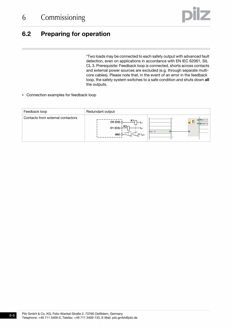
*Two loads may be connected to each safety output with advanced fault detection, even on applications in accordance with EN IEC 62061, SIL CL 3. Prerequisite: Feedback loop is connected, shorts across contacts and external power sources are excluded (e.g. through separate multi-core cables). Please note that, in the event of an error in the feedback loop, the safety system switches to a safe condition and shuts down all the outputs.
Connection examples for feedback loop
Feedback loop Redundant output
Contacts from external contactors.�
,-
,/.
���0�1
���0��1
��
,/
Pilz GmbH & Co. KG, Felix-Wankel-Straße 2, 73760 Ostfildern, GermanyTelephone: +49 711 3409-0, Telefax: +49 711 3409-133, E-Mail: [email protected]
6.2 Preparing for operation
6 Commissioning
6.2.4 Using the chip card Using the chip card 6-Inbetriebnahme_Chipkarte_einsetzen_1_wichtig_Kontaktflaeche_sauber
Inbetriebnahme_Chipkarte_einsetzen_2_wichtig_produkt_ausschalten
Inbetriebnahme_Chipkarte_einsetzen_3_Chipkarte_nicht verkantet
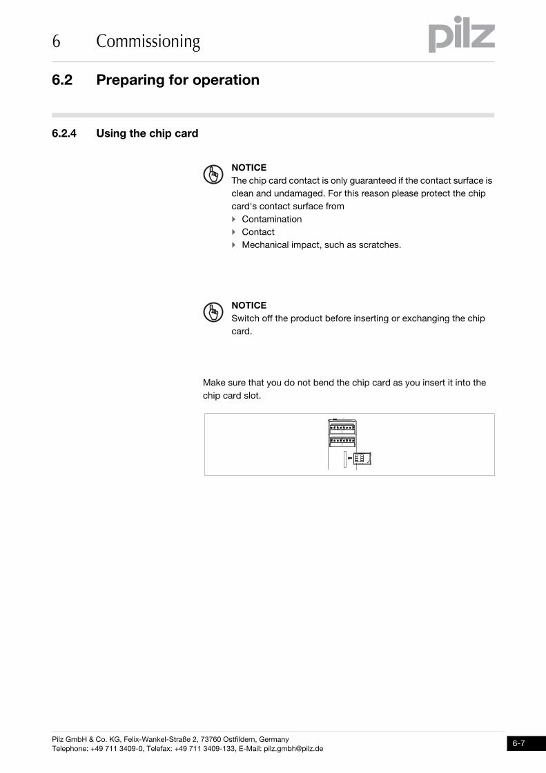
Make sure that you do not bend the chip card as you insert it into the chip card slot.
Inbetriebnahme_Chipkarte_einsetzen_4_Chipkarte_nicht verkantet_Bild_multi_mini
NOTICEThe chip card contact is only guaranteed if the contact surface is clean and undamaged. For this reason please protect the chip card's contact surface from Contamination Contact Mechanical impact, such as scratches.
NOTICESwitch off the product before inserting or exchanging the chip card.
Pilz GmbH & Co. KG, Felix-Wankel-Straße 2, 73760 Ostfildern, GermanyTelephone: +49 711 3409-0, Telefax: +49 711 3409-133, E-Mail: [email protected]
6-7
6.3 Connection example
6 Commissioning
6-8
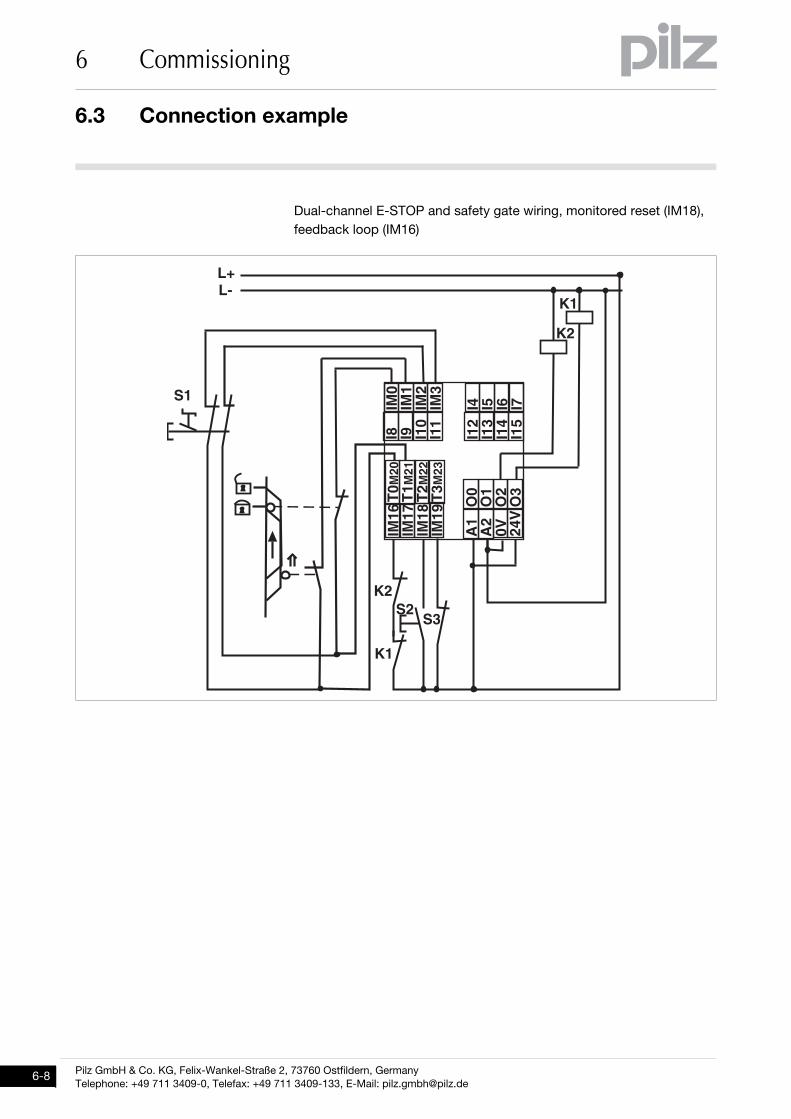
6.3Connection example6300Connection example6-Anschlussbeispiel_Basisgeräte_mini_BA
Dual-channel E-STOP and safety gate wiring, monitored reset (IM18), feedback loop (IM16)
���
���
���
���
�� � � ��
�� � ���
���
���
���
���
��
���
����
����
���
���
�����
�����
�����
��
��
��
��
��
��
��
���
��
��
��
��
��
��
����
����
Pilz GmbH & Co. KG, Felix-Wankel-Straße 2, 73760 Ostfildern, GermanyTelephone: +49 711 3409-0, Telefax: +49 711 3409-133, E-Mail: [email protected]
7.1 Rotary knob
7 Operation
77000OperationOperation7-7.1Rotary knob7100Rotary knob7-7.1.1 FunctionFunction7-Inbetriebnahme_Drehknopf_Funktion
The menu settings are made on the unit's display via a rotary knob. You have the option to make the settings on the knob by hand or with a screwdriver. If you make the settings with a screwdriver, the knob can remain within the unit.
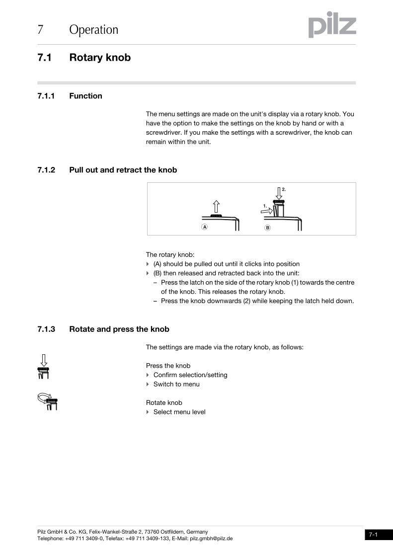
7.1.2 Pull out and retract the knob Pull out and retract the knob 7-Inbetriebnahme_Drehknopf_Bild
Inbetriebnahme_Drehknopf_Funktion_heraus_und_zurck
The rotary knob: (A) should be pulled out until it clicks into position (B) then released and retracted back into the unit:
– Press the latch on the side of the rotary knob (1) towards the centre of the knob. This releases the rotary knob.
– Press the knob downwards (2) while keeping the latch held down.
7.1.3 Rotate and press the knob Rotate and press the knob 7-Inbetriebnahme_Drehknopf_Funktion_drcken_drehen_anzeigen
The settings are made via the rotary knob, as follows:
Press the knob Confirm selection/setting Switch to menu
Rotate knob Select menu level
�
��
��
�
Pilz GmbH & Co. KG, Felix-Wankel-Straße 2, 73760 Ostfildern, GermanyTelephone: +49 711 3409-0, Telefax: +49 711 3409-133, E-Mail: [email protected]
7-1
7.2 Messages
7 Operation
7-2
7.2Messages7200Messages7-Betrieb_Meldungen_Basis_BA
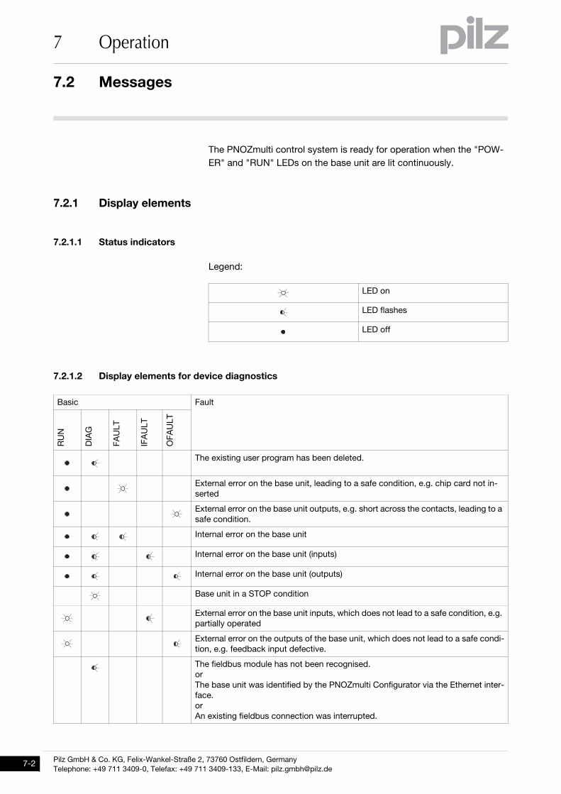
The PNOZmulti control system is ready for operation when the "POW-ER" and "RUN" LEDs on the base unit are lit continuously.
7.2.1 Display elementsDisplay elements7-
7.2.1.1 Status indicatorsStatus indicators7-Anzeige Legende 3x
Legend:
7.2.1.2 Display elements for device diagnosticsDisplay elements for device diagnostics7-Betrieb_Anzeige_mini_multi_Basis_BA
LED on
LED flashes
LED off
Basic Fault
RU
N
DIA
G
FAU
LT
IFA
ULT
OFA
ULT
The existing user program has been deleted.
External error on the base unit, leading to a safe condition, e.g. chip card not in-serted
External error on the base unit outputs, e.g. short across the contacts, leading to a safe condition.
Internal error on the base unit
Internal error on the base unit (inputs)
Internal error on the base unit (outputs)
Base unit in a STOP condition
External error on the base unit inputs, which does not lead to a safe condition, e.g. partially operated
External error on the outputs of the base unit, which does not lead to a safe condi-tion, e.g. feedback input defective.
The fieldbus module has not been recognised.orThe base unit was identified by the PNOZmulti Configurator via the Ethernet inter-face.orAn existing fieldbus connection was interrupted.
Pilz GmbH & Co. KG, Felix-Wankel-Straße 2, 73760 Ostfildern, GermanyTelephone: +49 711 3409-0, Telefax: +49 711 3409-133, E-Mail: [email protected]
7.2 Messages
7 Operation
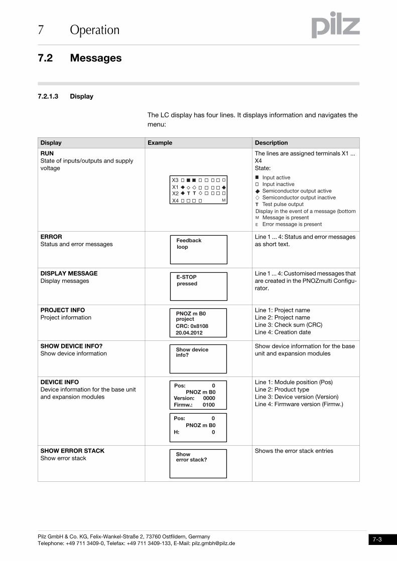
7.2.1.3 DisplayDisplay7-Betrieb_Display_multi_2_BA
The LC display has four lines. It displays information and navigates the menu:
Display Example Description
RUNState of inputs/outputs and supply voltage
The lines are assigned terminals X1 ... X4State:
ERRORStatus and error messages
Line 1 ... 4: Status and error messages as short text.
DISPLAY MESSAGEDisplay messages
Line 1 ... 4: Customised messages that are created in the PNOZmulti Configu-rator.
PROJECT INFOProject information
Line 1: Project nameLine 2: Project nameLine 3: Check sum (CRC)Line 4: Creation date
SHOW DEVICE INFO?Show device information
Show device information for the base unit and expansion modules
DEVICE INFODevice information for the base unit and expansion modules
Line 1: Module position (Pos)Line 2: Product typeLine 3: Device version (Version)Line 4: Firmware version (Firmw.)
SHOW ERROR STACKShow error stack
Shows the error stack entries
��������
� ��
��������������������� ��������������������� ���������������������������������������
����������������������������������������
�
�
�
����������������������������������������
2��'��#3����
4/)������%%�'
�5�6�&�*����7�#��8�9��$�����:��:��
);���'�<�#�����=
��%9�������������������
���%���9�����������5�6�&�*�
2��&�:9�����������
��%9�������������������
>9������������������������5�6�&�*�
);��������%��#3=
Pilz GmbH & Co. KG, Felix-Wankel-Straße 2, 73760 Ostfildern, GermanyTelephone: +49 711 3409-0, Telefax: +49 711 3409-133, E-Mail: [email protected]
7-3
7.2 Messages
7 Operation
7-4
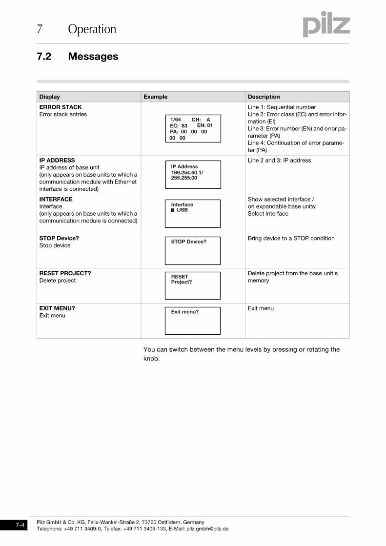
You can switch between the menu levels by pressing or rotating the knob.
ERROR STACKError stack entries
Line 1: Sequential numberLine 2: Error class (EC) and error infor-mation (EI)Line 3: Error number (EN) and error pa-rameter (PA)Line 4: Continuation of error parame-ter (PA)
IP ADDRESSIP address of base unit(only appears on base units to which a communication module with Ethernet interface is connected)
Line 2 and 3: IP address
INTERFACEInterface(only appears on base units to which a communication module is connected)
Show selected interface /on expandable base units:Select interface
STOP Device?Stop device
Bring device to a STOP condition
RESET PROJECT?Delete project
Delete project from the base unit's memory
EXIT MENU?Exit menu
Exit menu
Display Example Description
��+"�
���9���������������4�9����
�������
�459�����>9�����
���''��%%�" :��:"�:�+��:��:��
������#�����()*
)����?�<�#�=
84)4����7�#�=
4$���&�� =
Pilz GmbH & Co. KG, Felix-Wankel-Straße 2, 73760 Ostfildern, GermanyTelephone: +49 711 3409-0, Telefax: +49 711 3409-133, E-Mail: [email protected]
7.2 Messages
7 Operation
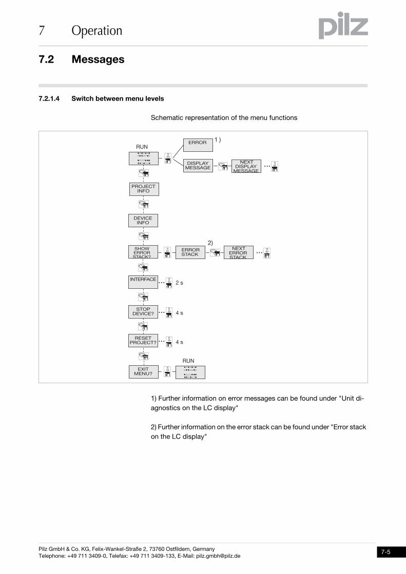
7.2.1.4 Switch between menu levels Switch between menu levels 7-Betrieb_Display_multi_2_Funktionsübersicht
Schematic representation of the menu functions
1) Further information on error messages can be found under "Unit di-agnostics on the LC display"
2) Further information on the error stack can be found under "Error stack on the LC display"
��� �
!� "�#��$%
��&�#��$%
' (��� � �)#*+
�,����$-+
���� � �)#*
�-$
�$�,���� � �)#*
. �
/�
�� ��!� "�#�+
000
�-$
000
�$���%)#� 000
� !��&�#�+ 000
/��
1��
1��
�� !2)3�� )4�
�$�,��� !2)3�� )4�
000
Pilz GmbH & Co. KG, Felix-Wankel-Straße 2, 73760 Ostfildern, GermanyTelephone: +49 711 3409-0, Telefax: +49 711 3409-133, E-Mail: [email protected]
7-5
7.2 Messages
7 Operation
7-6
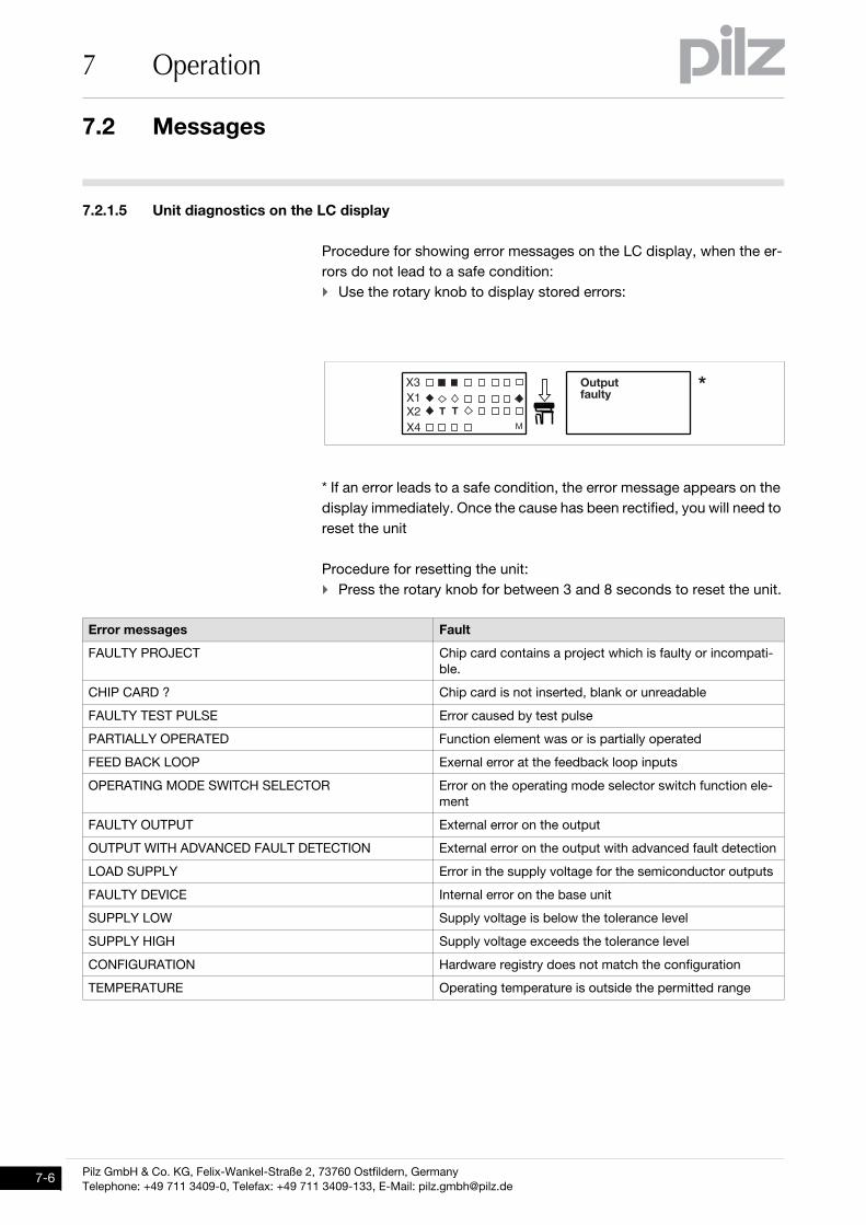
7.2.1.5 Unit diagnostics on the LC displayUnit diagnostics on the LC display7-Betrieb_Display_multi2_Diagnose
Procedure for showing error messages on the LC display, when the er-rors do not lead to a safe condition: Use the rotary knob to display stored errors:
* If an error leads to a safe condition, the error message appears on the display immediately. Once the cause has been rectified, you will need to reset the unit
Procedure for resetting the unit: Press the rotary knob for between 3 and 8 seconds to reset the unit.
Error messages Fault
FAULTY PROJECT Chip card contains a project which is faulty or incompati-ble.
CHIP CARD ? Chip card is not inserted, blank or unreadable
FAULTY TEST PULSE Error caused by test pulse
PARTIALLY OPERATED Function element was or is partially operated
FEED BACK LOOP Exernal error at the feedback loop inputs
OPERATING MODE SWITCH SELECTOR Error on the operating mode selector switch function ele-ment
FAULTY OUTPUT External error on the output
OUTPUT WITH ADVANCED FAULT DETECTION External error on the output with advanced fault detection
LOAD SUPPLY Error in the supply voltage for the semiconductor outputs
FAULTY DEVICE Internal error on the base unit
SUPPLY LOW Supply voltage is below the tolerance level
SUPPLY HIGH Supply voltage exceeds the tolerance level
CONFIGURATION Hardware registry does not match the configuration
TEMPERATURE Operating temperature is outside the permitted range
� �� ��� ��@
A��������
� ��
Pilz GmbH & Co. KG, Felix-Wankel-Straße 2, 73760 Ostfildern, GermanyTelephone: +49 711 3409-0, Telefax: +49 711 3409-133, E-Mail: [email protected]
7.2 Messages
7 Operation
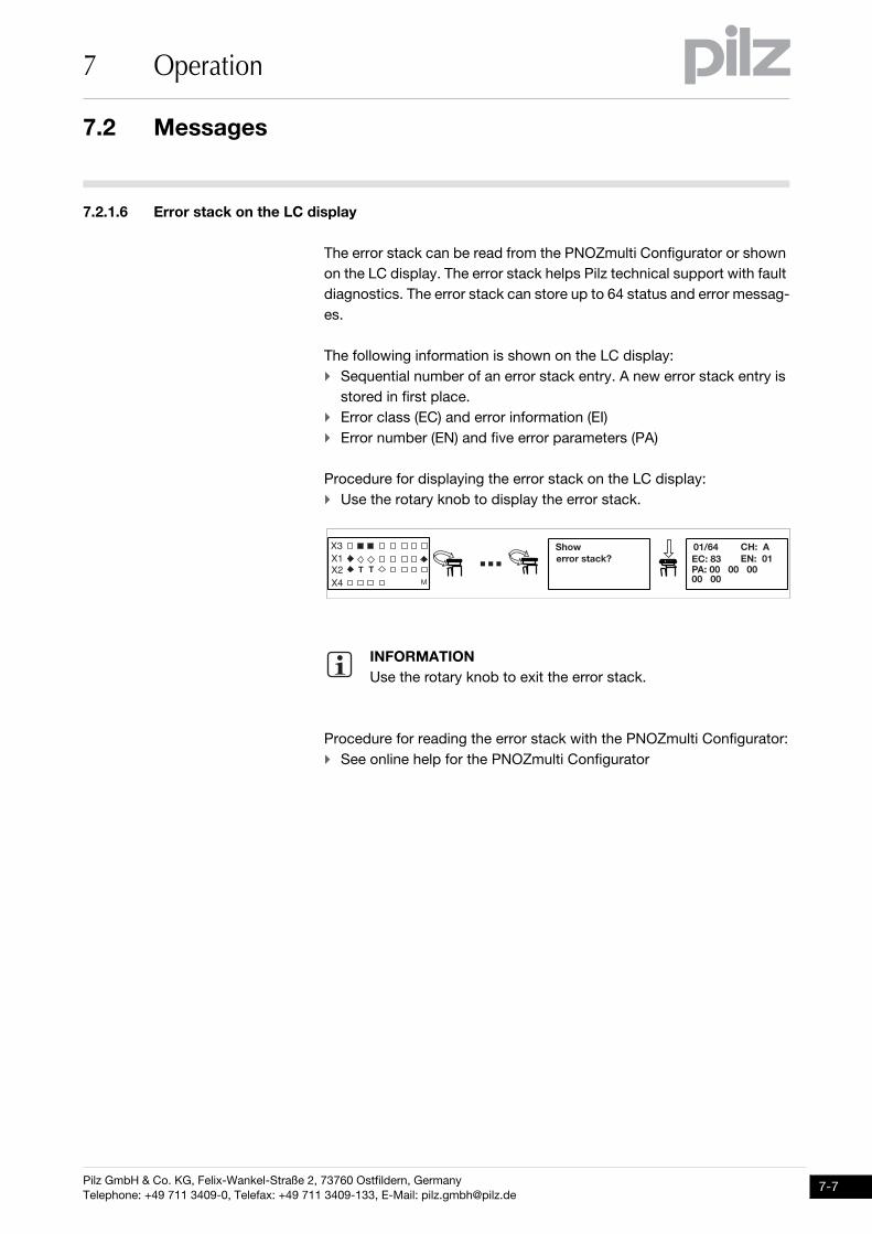
7.2.1.6 Error stack on the LC displayError stack on the LC display7-Betrieb_Display_multi2_erweiterte_Diagnose
The error stack can be read from the PNOZmulti Configurator or shown on the LC display. The error stack helps Pilz technical support with fault diagnostics. The error stack can store up to 64 status and error messag-es.
The following information is shown on the LC display: Sequential number of an error stack entry. A new error stack entry is
stored in first place. Error class (EC) and error information (EI) Error number (EN) and five error parameters (PA)
Procedure for displaying the error stack on the LC display: Use the rotary knob to display the error stack.
Procedure for reading the error stack with the PNOZmulti Configurator: See online help for the PNOZmulti Configurator
INFORMATIONUse the rotary knob to exit the error stack.
��+"�
��9��������������������
4�9��� 459����);��������%��#3=
��������
� ��
::: �>9���
Pilz GmbH & Co. KG, Felix-Wankel-Straße 2, 73760 Ostfildern, GermanyTelephone: +49 711 3409-0, Telefax: +49 711 3409-133, E-Mail: [email protected]
7-7

7 Operation
7-8
Pilz GmbH & Co. KG, Felix-Wankel-Straße 2, 73760 Ostfildern, GermanyTelephone: +49 711 3409-0, Telefax: +49 711 3409-133, E-Mail: [email protected]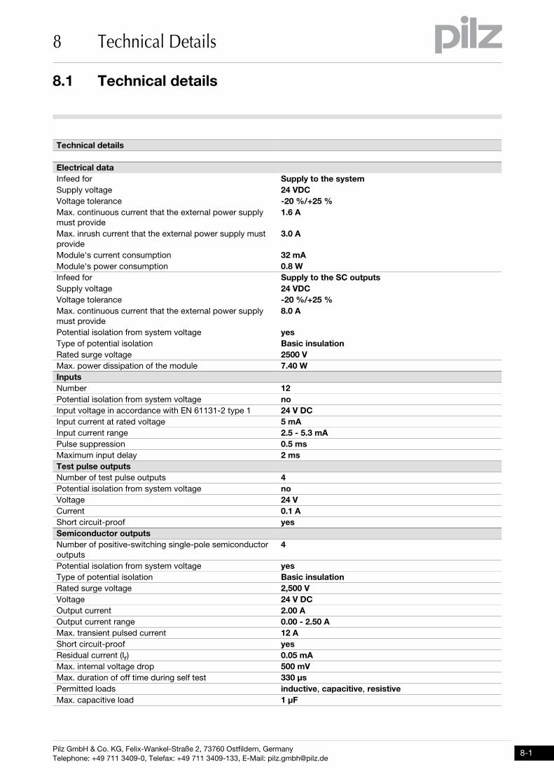
8.1 Technical details
8 Technical Details
88000Technical DetailsTechnical Details8-8.1Technical details8100Technical details8-][Technische Daten_multi_Basis_Multi_2
Technical details
Electrical dataInfeed for Supply to the systemSupply voltage 24 VDCVoltage tolerance -20 %/+25 %Max. continuous current that the external power supply must provide
1.6 A
Max. inrush current that the external power supply must provide
3.0 A
Module's current consumption 32 mAModule's power consumption 0.8 WInfeed for Supply to the SC outputsSupply voltage 24 VDCVoltage tolerance -20 %/+25 %Max. continuous current that the external power supply must provide
8.0 A
Potential isolation from system voltage yesType of potential isolation Basic insulationRated surge voltage 2500 VMax. power dissipation of the module 7.40 WInputsNumber 12Potential isolation from system voltage noInput voltage in accordance with EN 61131-2 type 1 24 V DCInput current at rated voltage 5 mAInput current range 2.5 - 5.3 mAPulse suppression 0.5 msMaximum input delay 2 msTest pulse outputsNumber of test pulse outputs 4Potential isolation from system voltage noVoltage 24 VCurrent 0.1 AShort circuit-proof yesSemiconductor outputsNumber of positive-switching single-pole semiconductor outputs
4
Potential isolation from system voltage yesType of potential isolation Basic insulationRated surge voltage 2,500 VVoltage 24 V DCOutput current 2.00 AOutput current range 0.00 - 2.50 AMax. transient pulsed current 12 AShort circuit-proof yesResidual current (Ir) 0.05 mAMax. internal voltage drop 500 mVMax. duration of off time during self test 330 µsPermitted loads inductive, capacitive, resistiveMax. capacitive load 1 µF
Pilz GmbH & Co. KG, Felix-Wankel-Straße 2, 73760 Ostfildern, GermanyTelephone: +49 711 3409-0, Telefax: +49 711 3409-133, E-Mail: [email protected]
8-1
8.1 Technical details
8 Technical Details
8-2
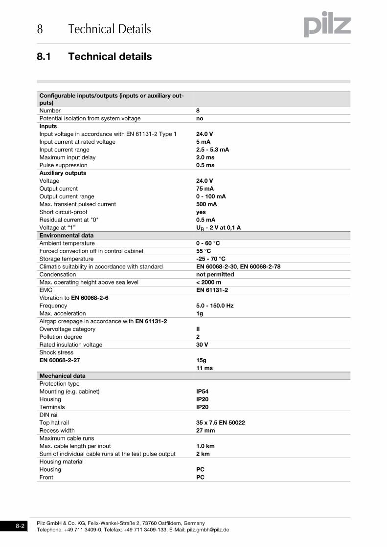
Configurable inputs/outputs (inputs or auxiliary out-puts)Number 8Potential isolation from system voltage noInputsInput voltage in accordance with EN 61131-2 Type 1 24.0 VInput current at rated voltage 5 mAInput current range 2.5 - 5.3 mAMaximum input delay 2.0 msPulse suppression 0.5 msAuxiliary outputsVoltage 24.0 VOutput current 75 mAOutput current range 0 - 100 mAMax. transient pulsed current 500 mAShort circuit-proof yesResidual current at "0" 0.5 mAVoltage at “1” UB - 2 V at 0,1 AEnvironmental dataAmbient temperature 0 - 60 °CForced convection off in control cabinet 55 °CStorage temperature -25 - 70 °CClimatic suitability in accordance with standard EN 60068-2-30, EN 60068-2-78Condensation not permittedMax. operating height above sea level < 2000 m EMC EN 61131-2Vibration to EN 60068-2-6Frequency 5.0 - 150.0 HzMax. acceleration 1gAirgap creepage in accordance with EN 61131-2Overvoltage category IIPollution degree 2Rated insulation voltage 30 VShock stressEN 60068-2-27 15g
11 msMechanical dataProtection typeMounting (e.g. cabinet) IP54Housing IP20Terminals IP20DIN railTop hat rail 35 x 7.5 EN 50022Recess width 27 mmMaximum cable runsMax. cable length per input 1.0 kmSum of individual cable runs at the test pulse output 2 kmHousing materialHousing PCFront PC
Pilz GmbH & Co. KG, Felix-Wankel-Straße 2, 73760 Ostfildern, GermanyTelephone: +49 711 3409-0, Telefax: +49 711 3409-133, E-Mail: [email protected]
8.1 Technical details
8 Technical Details
Si-Kennzahlen_alle
Si_Kennzahlen_Erläuterung_1
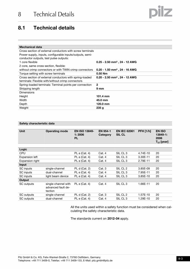
All the units used within a safety function must be considered when cal-culating the safety characteristic data.
Technische Daten_Satz Normen
The standards current on 2012-04 apply.
Cross section of external conductors with screw terminalsPower supply, inputs, configurable inputs/outputs, semi-conductor outputs, test pulse outputs:1 core flexible 0.25 - 2.50 mm² , 24 - 12 AWG2 core, same cross section, flexible:without crimp connectors or with TWIN crimp connectors 0.20 - 1.50 mm² , 24 - 16 AWGTorque setting with screw terminals 0.50 NmCross section of external conductors with spring-loaded terminals: Flexible with/without crimp connectors
0.20 - 2.50 mm² , 24 - 12 AWG
Spring-loaded terminals: Terminal points per connection 2Stripping length 9 mmDimensionsHeight 101.4 mmWidth 45.0 mmDepth 120.0 mmWeight 235 g
Safety characteristic data
Unit Operating mode EN ISO 13849-1: 2006PL
EN 954-1Category
EN IEC 62061SIL CL
PFH [1/h] EN ISO 13849-1: 2006TM [year]
LogicCPU PL e (Cat. 4) Cat. 4 SIL CL 3 4.74E-10 20Expansion left PL e (Cat. 4) Cat. 4 SIL CL 3 3.30E-11 20Expansion right PL e (Cat. 4) Cat. 4 SIL CL 3 2.79E-11 20InputSC inputs single-channel PL d (Cat. 2) Cat. 3 SIL CL 2 3.85E-09 20SC inputs dual-channel PL e (Cat. 4) Cat. 4 SIL CL 3 7.95E-11 20SC inputs light beam device PL e (Cat. 4) Cat. 4 SIL CL 3 3.85E-10 20OutputSC outputs single-channel with
advanced fault de-tection
PL e (Cat. 4) Cat. 4 SIL CL 3 1.66E-11 20
SC outputs single-channel PL d (Cat. 2) Cat. 3 SIL CL 2 1.57E-10 20SC outputs dual-channel PL e (Cat. 4) Cat. 4 SIL CL 3 1.29E-10 20
Mechanical data
Pilz GmbH & Co. KG, Felix-Wankel-Straße 2, 73760 Ostfildern, GermanyTelephone: +49 711 3409-0, Telefax: +49 711 3409-133, E-Mail: [email protected]
8-3
8.2 Maximum capacitive load C (mF) with load current I (A) at the semiconductor outputs
8 Technical Details
8-4
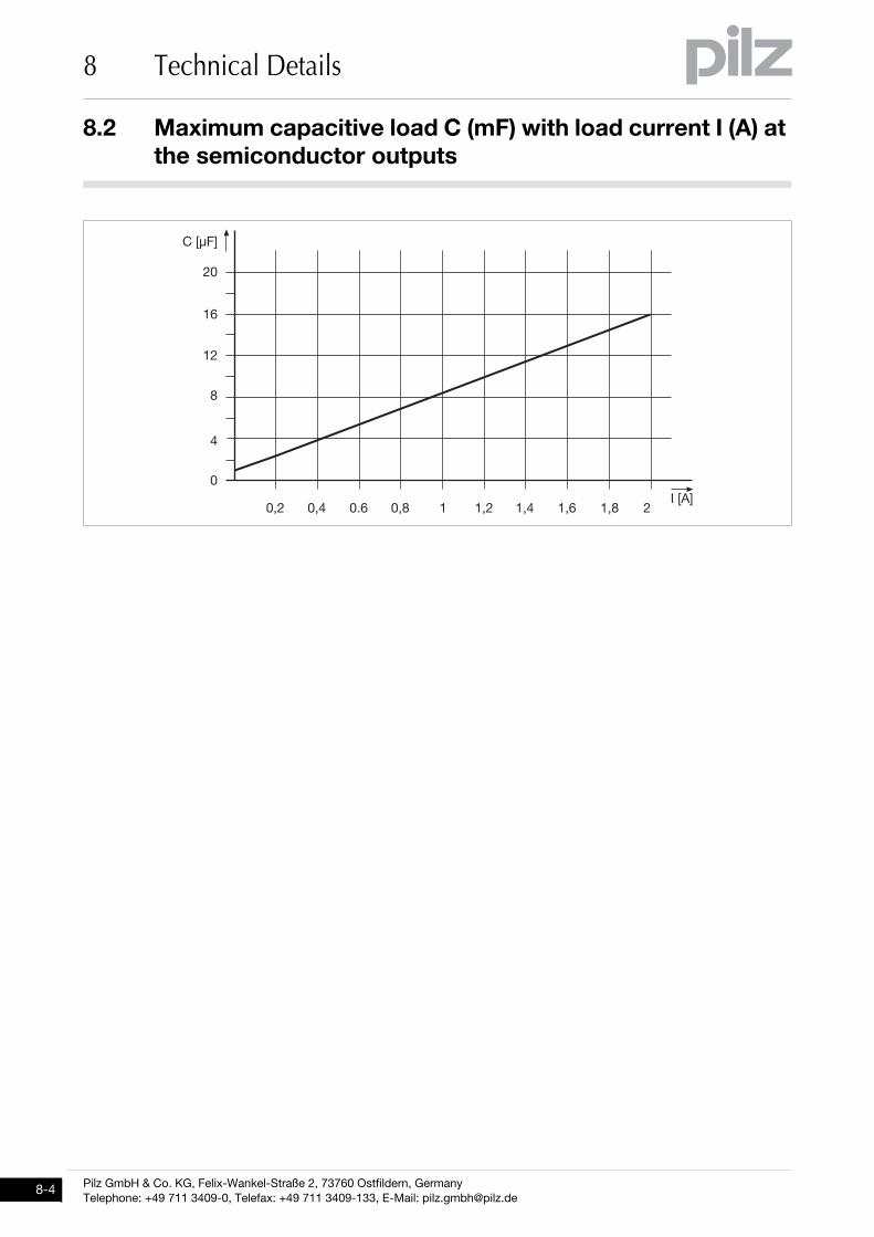
8.2Maximum capacitive load C (μF) with load current I (A) at the semiconductor outputs8200Maximum capacitive load C (μF) with load current I (A) at the semiconductor outputs8-Kapazitive Last
1
5
./
.6
/7
7
78/ 781 706 785 . .8/ .81 .86 .85 /��9):
#�9;%:
Pilz GmbH & Co. KG, Felix-Wankel-Straße 2, 73760 Ostfildern, GermanyTelephone: +49 711 3409-0, Telefax: +49 711 3409-133, E-Mail: [email protected]
8.3 Maximum permitted total current of the semiconductor outputs
8 Technical Details
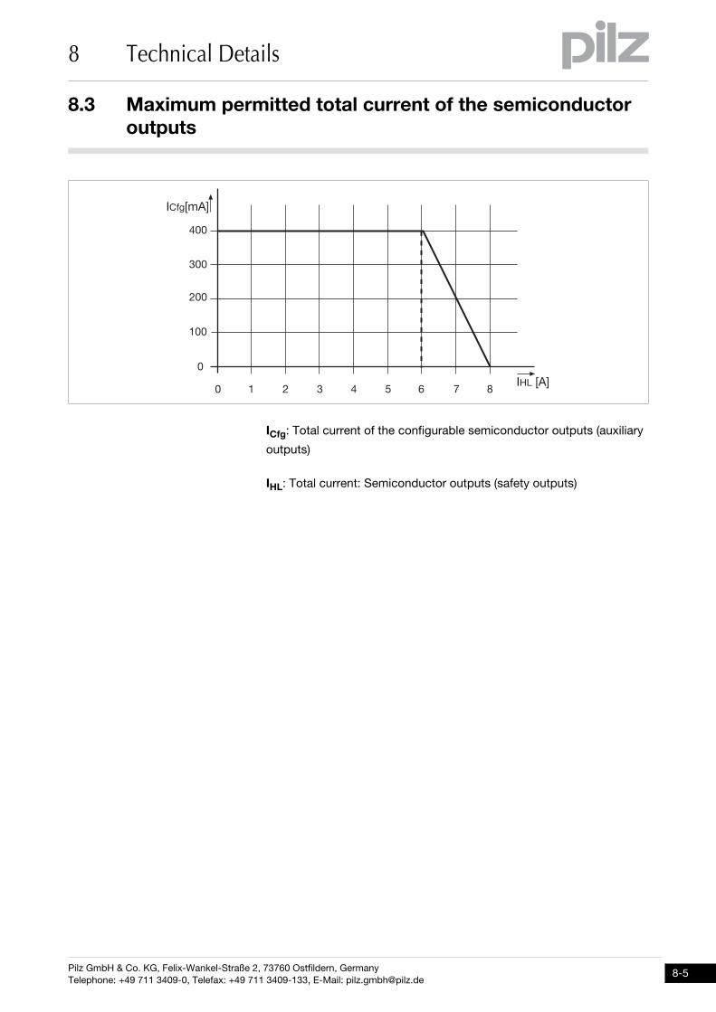
8.3Maximum permitted total current of the semiconductor outputs8300Maximum permitted total current of the semiconductor outputs8-Maximal zulässiger Summenstrom der Halbleiterausgänge
ICfg: Total current of the configurable semiconductor outputs (auxiliary
outputs)
IHL: Total current: Semiconductor outputs (safety outputs)
.77
/77
<77
177
7
. / < 1 = 6 > 5�'2�9):
�#��9�):
7
Pilz GmbH & Co. KG, Felix-Wankel-Straße 2, 73760 Ostfildern, GermanyTelephone: +49 711 3409-0, Telefax: +49 711 3409-133, E-Mail: [email protected]
8-5
8.4 Maximum permitted humidity
8 Technical Details
8-6
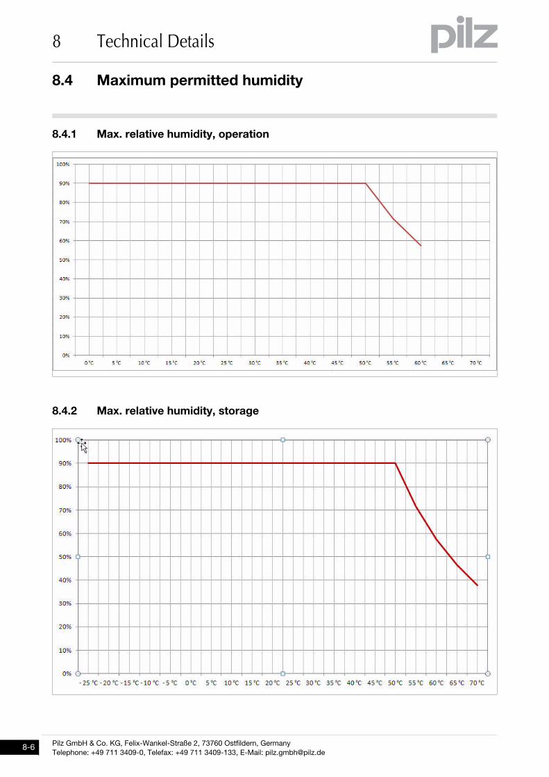
8.4Maximum permitted humidity8400Maximum permitted humidity8-8.4.1 Max. relative humidity, operationMax. relative humidity, operation8-Max. Luftfeuchte Betrieb
8.4.2 Max. relative humidity, storageMax. relative humidity, storage8-Max. Luftfeuchte Lagerung
Pilz GmbH & Co. KG, Felix-Wankel-Straße 2, 73760 Ostfildern, GermanyTelephone: +49 711 3409-0, Telefax: +49 711 3409-133, E-Mail: [email protected]

8.5 Order reference
8 Technical Details
8.5Order reference8500Order reference8-Bestelldaten PNOZ m B0
Bestelldaten Zubehör PNOZ mm0/0.1/0.2p
Bestelldaten Zubehör Abschlussstecker multi2
Bestelldaten Zubehör Kabel PNOZ mm0/0.1p
Order reference
Product type Features Order no.PNOZ m B0 Base unit 772 100
Order reference: Accesso-ries
Product Type Features Order no.PNOZ s Set1 spring-loaded terminals
1 set of spring-loaded terminals 751 008
PNOZ s Set1 screw termi-nals
1 set of screw terminals 750 008
Order reference: Terminator, jumper
Product type Features Order no.PNOZ mm0.xp terminator left
Terminator, black/yellow, x1 779 261
Order reference: Cable
Product Type Features Order no.PSSu A USB-CAB03 Mini USB cable, 3 m 312 992PSSu A USB-CAB05 Mini USB cable, 5 m 312 993
Pilz GmbH & Co. KG, Felix-Wankel-Straße 2, 73760 Ostfildern, GermanyTelephone: +49 711 3409-0, Telefax: +49 711 3409-133, E-Mail: [email protected]
8-7
8 Technical Details
8-8
Pilz GmbH & Co. KG, Felix-Wankel-Straße 2, 73760 Ostfildern, GermanyTelephone: +49 711 3409-0, Telefax: +49 711 3409-133, E-Mail: [email protected]
...
1002
660-
EN
-01,
201
2-07
Prin
ted
in G
erm
any
© P
ilz G
mbH
& C
o. K
G, 2
011
+49 711 [email protected]
Pilz GmbH & Co. KGFelix-Wankel-Straße 273760 Ostfildern, GermanyTelephone: +49 711 3409-0Telefax: +49 711 3409-133E-Mail: [email protected]: www.pilz.com
Technical supportIn many countries we are represented by our subsidiaries and sales partners.
Please refer to our homepage for further details or contact our headquarters.
Indu
raN
ET
p®, P
ilz®, P
IT®, P
MC
prot
ego®
, PM
I®, P
NO
Z®, P
rimo®
, PS
EN
®, P
SS
®, P
VIS
®, S
afet
yBU
S p
®, S
afet
yEY
E®, S
afet
yNE
T p®
, the
spi
rit o
f saf
ety®
are
regi
ster
ed a
nd p
rote
cted
trad
emar
ks
of P
ilz G
mbH
& C
o. K
G in
som
e co
untr
ies.
We
wou
ld p
oint
out
that
pro
duct
feat
ures
may
var
y fr
om th
e de
tails
sta
ted
in th
is d
ocum
ent,
depe
ndin
g on
the
stat
us a
t the
tim
e of
pub
licat
ion
and
the
scop
e of
the
equi
pmen
t. W
e ac
cept
no
resp
onsi
bilit
y fo
r th
e va
lidity
, acc
urac
y an
d en
tiret
y of
the
text
and
gra
phic
s pr
esen
ted
in th
is in
form
atio
n. P
leas
e co
ntac
t our
Tec
hnic
al S
uppo
rt if
you
hav
e an
y qu
estio
ns.
Contact address