
Philippe BARRADE, Alain BOUSCAYROL, Philippe DELARUE ... · Philippe BARRADE, Alain BOUSCAYROL,...
17
EMR’11 Lausanne July 2011 Joint Summer School EMR’11 “Energetic Macroscopic Representation” Philippe BARRADE , Alain BOUSCAYROL, Philippe DELARUE,Walter LHOMME
Transcript of Philippe BARRADE, Alain BOUSCAYROL, Philippe DELARUE ... · Philippe BARRADE, Alain BOUSCAYROL,...
EMR’11 Lausanne July 2011
Joint Summer School EMR’11 “Energetic Macroscopic Representation”
Philippe BARRADE, Alain BOUSCAYROL, Philippe DELARUE,Walter LHOMME
EMR’11, Lausanne, July 2011 2
• Introduction
• Input filter oscillations – Structure and conventional control scheme – From oscillations rejection to instabilities
• Merged control – Objectives and tuning parameters – Merged control loops – Modeling and sizing rules – Input filter stability
• Experimental validation – Stability abacus – Results
• Conclusion
- Content -
EMR’11, Lausanne, July 2011 3
• General frame – DC/DC or 3 phases DC/AC converters – Feeding from a DC source via a 2nd order low pass filter
• Depending on the control of the converter – Some input filter oscillations can occur – In extreme cases, instabilities can be observed
• Depending on the operating point – Reference output power, DC feeding voltage
• Main goal – Allow the input filter stabilization by the appropriate control of the converter
• Obtained from an Energetic Macroscopic Representation (EMR)
- Outline -
EMR’11, Lausanne, July 2011 4
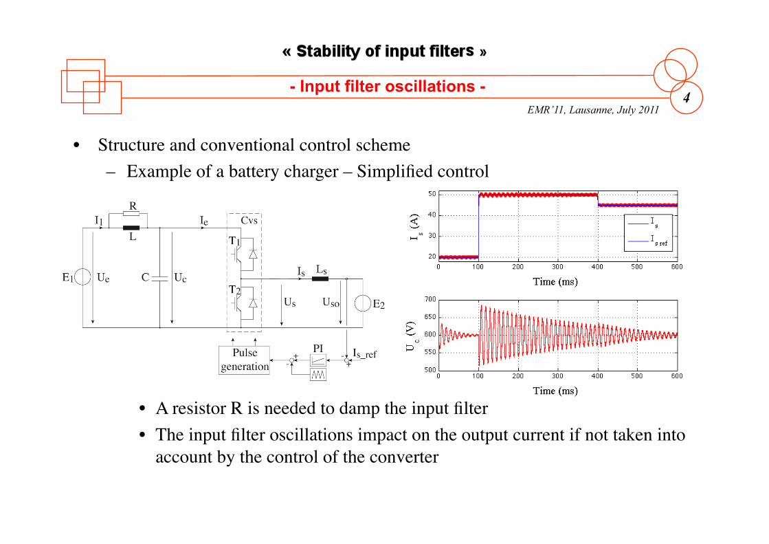
• Structure and conventional control scheme – Example of a battery charger – Simplified control
• A resistor R is needed to damp the input filter • The input filter oscillations impact on the output current if not taken into
account by the control of the converter
- Input filter oscillations -
EMR’11, Lausanne, July 2011 5
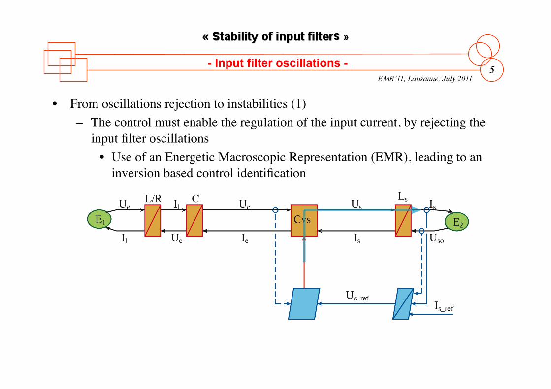
• From oscillations rejection to instabilities (1) – The control must enable the regulation of the input current, by rejecting the
input filter oscillations • Use of an Energetic Macroscopic Representation (EMR), leading to an
inversion based control identification
- Input filter oscillations -
EMR’11, Lausanne, July 2011 6
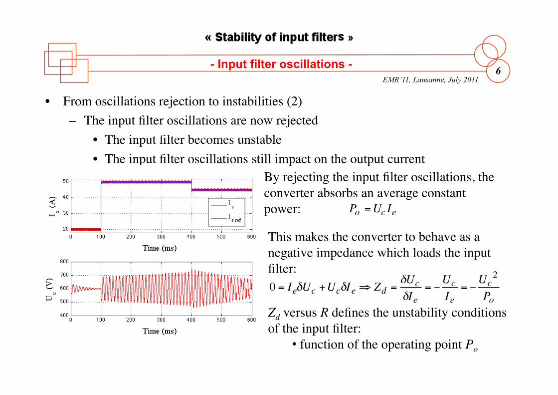
• From oscillations rejection to instabilities (2) – The input filter oscillations are now rejected
• The input filter becomes unstable • The input filter oscillations still impact on the output current
ripple
€
0 = IeδUc +UcδIe ⇒ Zd =δUcδIe
= −UcIe
= −Uc
2
Po
€
Po =Uc Ie
By rejecting the input filter oscillations, the converter absorbs an average constant power:
This makes the converter to behave as a negative impedance which loads the input filter:
Zd versus R defines the unstability conditions of the input filter:
• function of the operating point Po
- Input filter oscillations -
EMR’11, Lausanne, July 2011 7
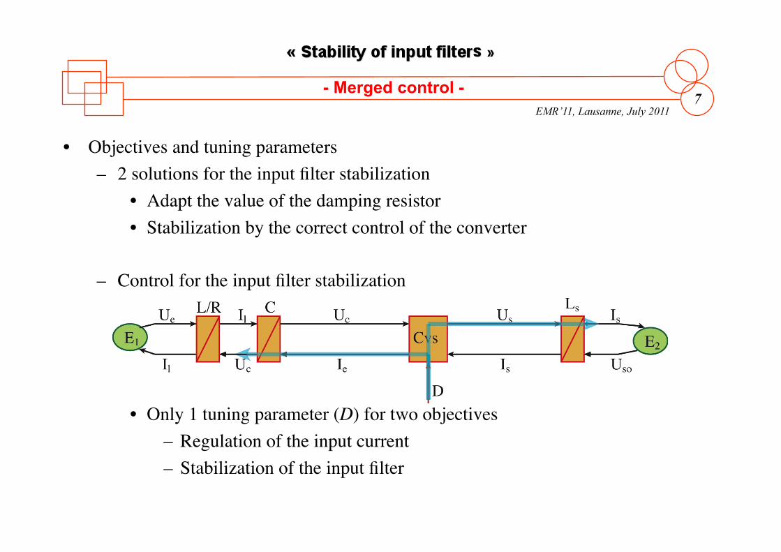
• Objectives and tuning parameters – 2 solutions for the input filter stabilization
• Adapt the value of the damping resistor • Stabilization by the correct control of the converter
– Control for the input filter stabilization
• Only 1 tuning parameter (D) for two objectives – Regulation of the input current – Stabilization of the input filter
- Merged control -
EMR’11, Lausanne, July 2011 8
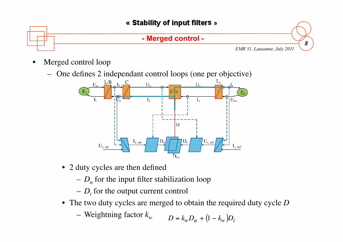
• Merged control loop – One defines 2 independant control loops (one per objective)
• 2 duty cycles are then defined – Du for the input filter stabilization loop – Di for the output current control
• The two duty cycles are merged to obtain the required duty cycle D – Weightning factor kw
€
D = kwDu + 1 − kw( )Di
- Merged control -
EMR’11, Lausanne, July 2011 9
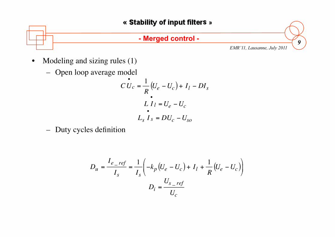
• Modeling and sizing rules (1) – Open loop average model
– Duty cycles definition
€
CU•c =
1RUe −Uc( ) + Il − DIs
L I•l =Ue −Uc
Ls I•s = DUc −Uso
€
Du =Ie _ refIs
=1Is
−kp Ue −Uc( ) + Il +1RUe −Uc( )
⎛
⎝ ⎜
⎞
⎠ ⎟
Di =Us _ refUc
- Merged control -
EMR’11, Lausanne, July 2011 10
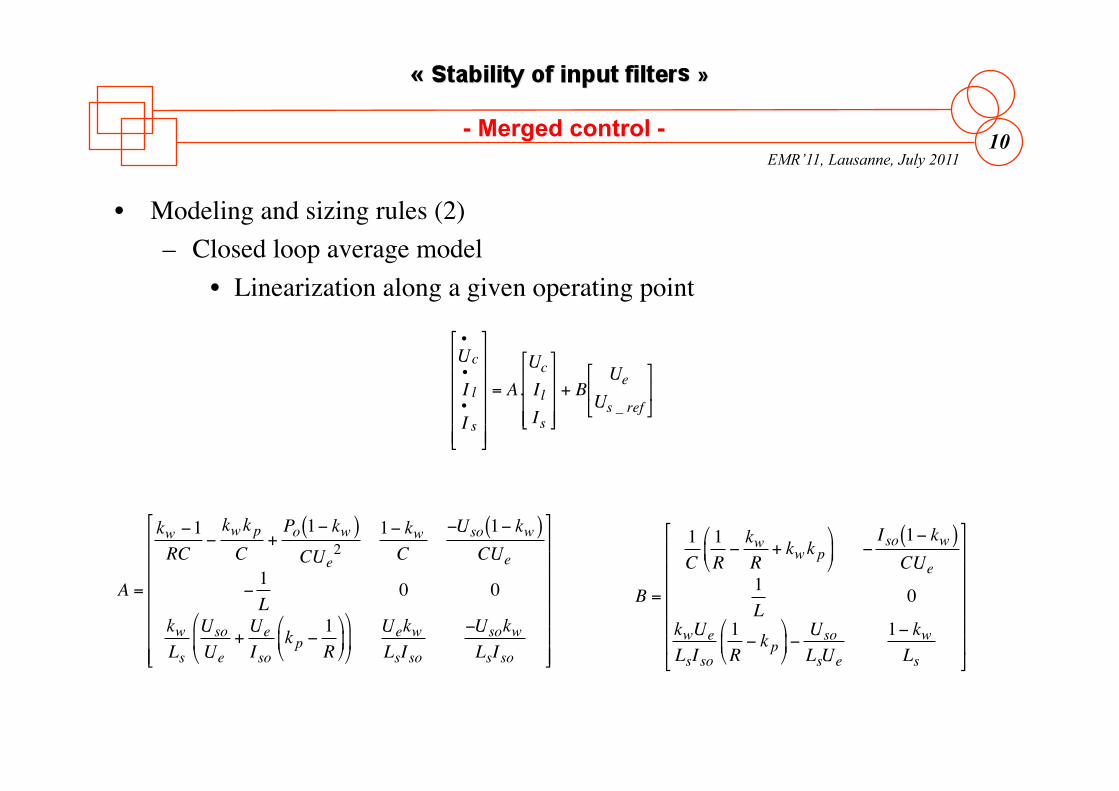
• Modeling and sizing rules (2) – Closed loop average model
• Linearization along a given operating point
€
U•c
I•l
I•s
⎡
⎣
⎢ ⎢ ⎢ ⎢ ⎢
⎤
⎦
⎥ ⎥ ⎥ ⎥ ⎥
= A.UcIlIs
⎡
⎣
⎢ ⎢ ⎢
⎤
⎦
⎥ ⎥ ⎥
+ BUe
Us _ ref
⎡
⎣ ⎢
⎤
⎦ ⎥
€
A =
kw −1RC
−kwk pC
+Po 1− kw( )CUe
21− kwC
−Uso 1− kw( )CUe
−1L
0 0
kwLs
UsoUe
+UeIso
k p −1R
⎛
⎝ ⎜
⎞
⎠ ⎟
⎛
⎝ ⎜
⎞
⎠ ⎟
UekwLsIso
−UsokwLsIso
⎡
⎣
⎢ ⎢ ⎢ ⎢ ⎢ ⎢ ⎢
⎤
⎦
⎥ ⎥ ⎥ ⎥ ⎥ ⎥ ⎥
€
B =
1C
1R−kwR
+ kwk p⎛
⎝ ⎜
⎞
⎠ ⎟ −
Iso 1− kw( )CUe
1L
0
kwUeLsIso
1R− k p
⎛
⎝ ⎜
⎞
⎠ ⎟ −
UsoLsUe
1− kwLs
⎡
⎣
⎢ ⎢ ⎢ ⎢ ⎢ ⎢
⎤
⎦
⎥ ⎥ ⎥ ⎥ ⎥ ⎥
- Merged control -
EMR’11, Lausanne, July 2011 11
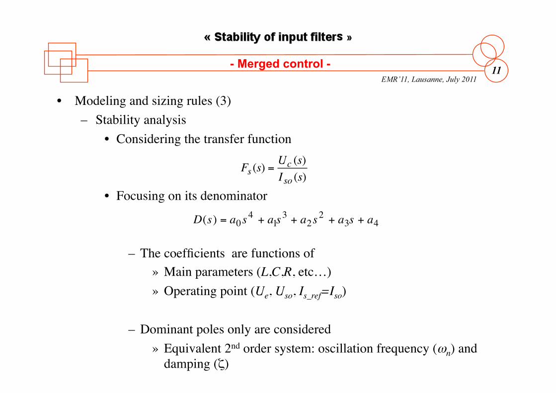
• Modeling and sizing rules (3) – Stability analysis
• Considering the transfer function
• Focusing on its denominator
– The coefficients are functions of » Main parameters (L,C,R, etc…) » Operating point (Ue, Uso, Is_ref=Iso)
– Dominant poles only are considered » Equivalent 2nd order system: oscillation frequency (ωn) and
damping (ζ)
€
Fs (s) =Uc (s)Iso (s)
€
D(s) = a0s4 + a1s
3 + a2s2 + a3s + a4
- Merged control -
EMR’11, Lausanne, July 2011 12
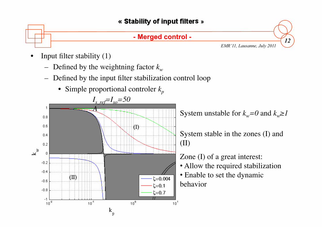
• Input filter stability (1) – Defined by the weightning factor kw – Defined by the input filter stabilization control loop
• Simple proportional controler kp
12
System unstable for kw=0 and kw≥1
Is_ref=Iso=50A
System stable in the zones (I) and (II)
Zone (I) of a great interest: • Allow the required stabilization • Enable to set the dynamic behavior
- Merged control -
EMR’11, Lausanne, July 2011 13
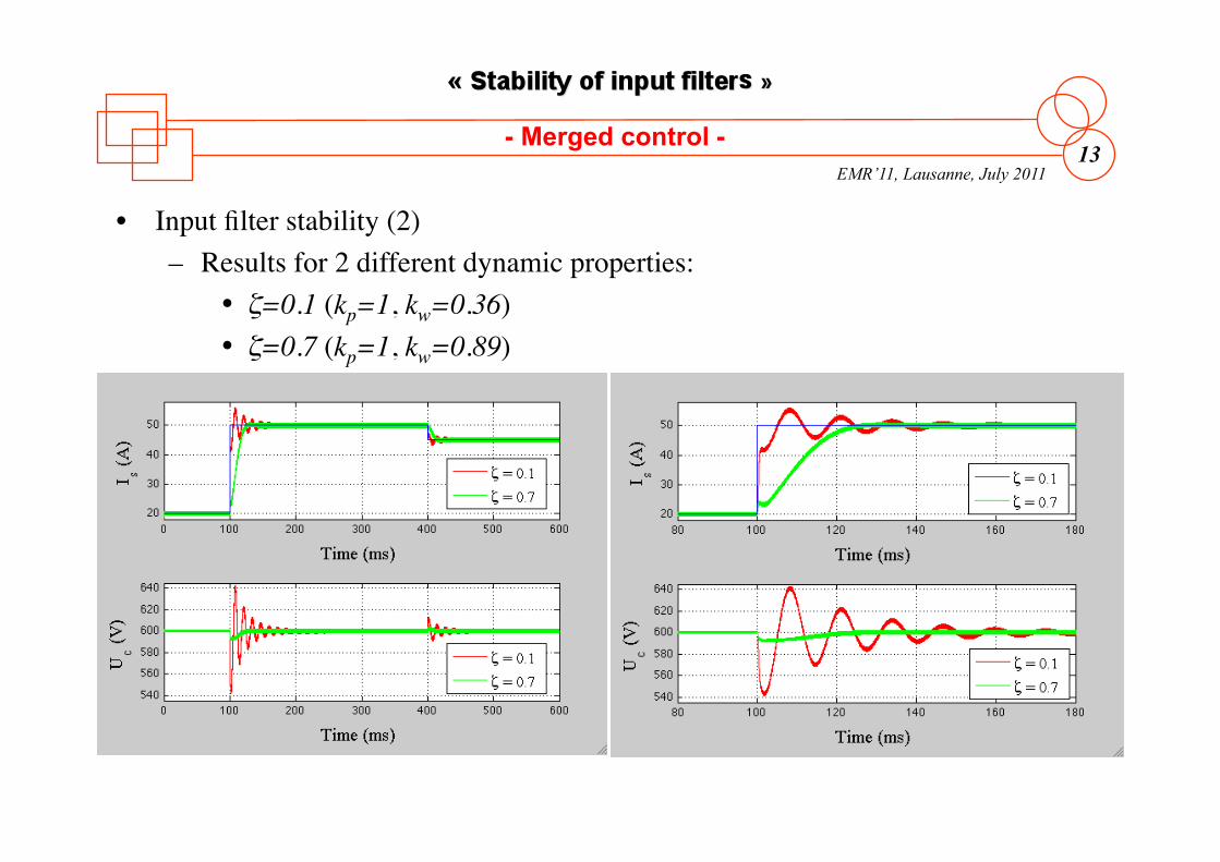
• Input filter stability (2) – Results for 2 different dynamic properties:
• ζ=0.1 (kp=1, kw=0.36) • ζ=0.7 (kp=1, kw=0.89)
- Merged control -
EMR’11, Lausanne, July 2011 14
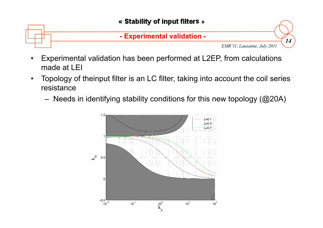
• Experimental validation has been performed at L2EP, from calculations made at LEI
• Topology of theinput filter is an LC filter, taking into account the coil series resistance – Needs in identifying stability conditions for this new topology (@20A)
- Experimental validation -
EMR’11, Lausanne, July 2011 15
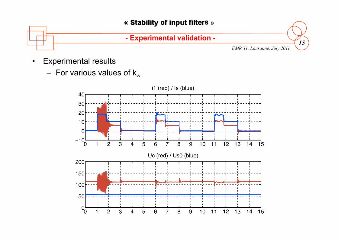
• Experimental results – For various values of kw
- Experimental validation -
EMR’11, Lausanne, July 2011 16
• An new and original method for the stabilization of input filter has been proposed
• This method has been identified thanks to an energetic macroscopic representation – Allows the identification of efficients control structures
• The model of the system and its control has shown: – The control structure based on an inversion method leads to the
effective input filter stabilization – One can moreover adjust the dynamic behavior
- Conclusion -
EMR’11, Lausanne, July 2011 17
• [1] R.D. Middlebrook, S. Cuk, “A general unified approach to modelling switching converters power stages”, IEEE PESC Rec. pp 18-34, 1976.
• [2] R.D. Middlebrook, “Input filter considerations in design and application of switching regulators”, IEEE Industry Applications annual meeting, 1976
• [3] P. Barrade, “Comportement dynamique des ensembles filter-convertisseur”, PhD thesism Institut National Polytechnique de Toulouse, France, 1997.
• [4] F. Barruel, N. Retiere, J. Schanen, A Caisley, “Stability approach for vehicles DC power network: application to aircraft on-board system”, Power Electronics Specialists Conference, PESC’05, pp 1163-1169, june 16th, 2005.
• [5] X.G. Feng, J.J. Liu, F.C. Lee, “Impedance specifications for stable DC distributed power systems”, IEEE Transactions on Power Electronics, vol. 17, pp. 157-162, 2002.
• [6] Ph. Delarue, A. Bouscayrol, A. Tounzi, X. Guillaud, G. Lancigu, “Modelling, control and simulation of an overall wind energy conversion system", Renewable Energy, vol. 28, no. 8, pp. 1159-1324, July 2003.
• [7] K. Chen, A. Bouscayrol, W. Lhomme, "Energetic macroscopic representation and inversion-based control: application to an electric vehicle with an electrical differential", Journal of Asian Electric Vehicles, Vol. 6, N°. 1, pages. 1097-1102, 6-2008.
- References -