Operating Instructions INTORQ 14.105 und 14i.intorqbrakes.ru/u/39/825206958511e89400dfd287238... ·...
24
Operating Instructions INTORQ 14.105 und 14.115 Electromagnetic clutches and brakes j setting the standard www.intorq.de
Transcript of Operating Instructions INTORQ 14.105 und 14i.intorqbrakes.ru/u/39/825206958511e89400dfd287238... ·...
Operating Instructions INTORQ 14.105 und 14.115Electromagnetic clutches and brakes
j
setting the standard
www.intorq.de
j | BA 14.0175−EN | 11/2007
2
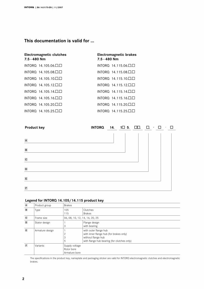
This documentation is valid for ...
Electromagnetic clutches Electromagnetic brakes
7.5 − 480 Nm 7.5 − 480 Nm
INTORQ 14.105.06.�.� INTORQ 14.115.06.�.�
INTORQ 14.105.08.�.� INTORQ 14.115.08.�.�
INTORQ 14.105.10.�.� INTORQ 14.115.10.�.�
INTORQ 14.105.12.�.� INTORQ 14.115.12.�.�
INTORQ 14.105.14.�.� INTORQ 14.115.14.�.�
INTORQ 14.105.16.�.� INTORQ 14.115.16.�.�
INTORQ 14.105.20.�.� INTORQ 14.115.20.�.�
INTORQ 14.105.25.�.� INTORQ 14.115.25.�.�
Product key INTORQ 14. 1� 5. ��. �.
− � − �
�
�
�
�
�
�
Legend for INTORQ 14.105/14.115 product key
� Product group Brakes
� Type 105
115
Clutches
Brakes
� Frame size 06, 08, 10, 12, 14, 16, 20, 25
� Stator design 1
3
Flange design
with bearing
� Armature design 1
2
3
5
with outer flange hub
with inner flange hub (for brakes only)
without flange hub
with flange hub bearing (for clutches only)
� Variants Supply voltage
Rotor bore
Armature bore
The specifications in the product key, nameplate and packaging sticker are valid for INTORQ electromagnetic clutches and electromagnetic
brakes.
j | BA 14.0175−EN | 11/2007
i
3
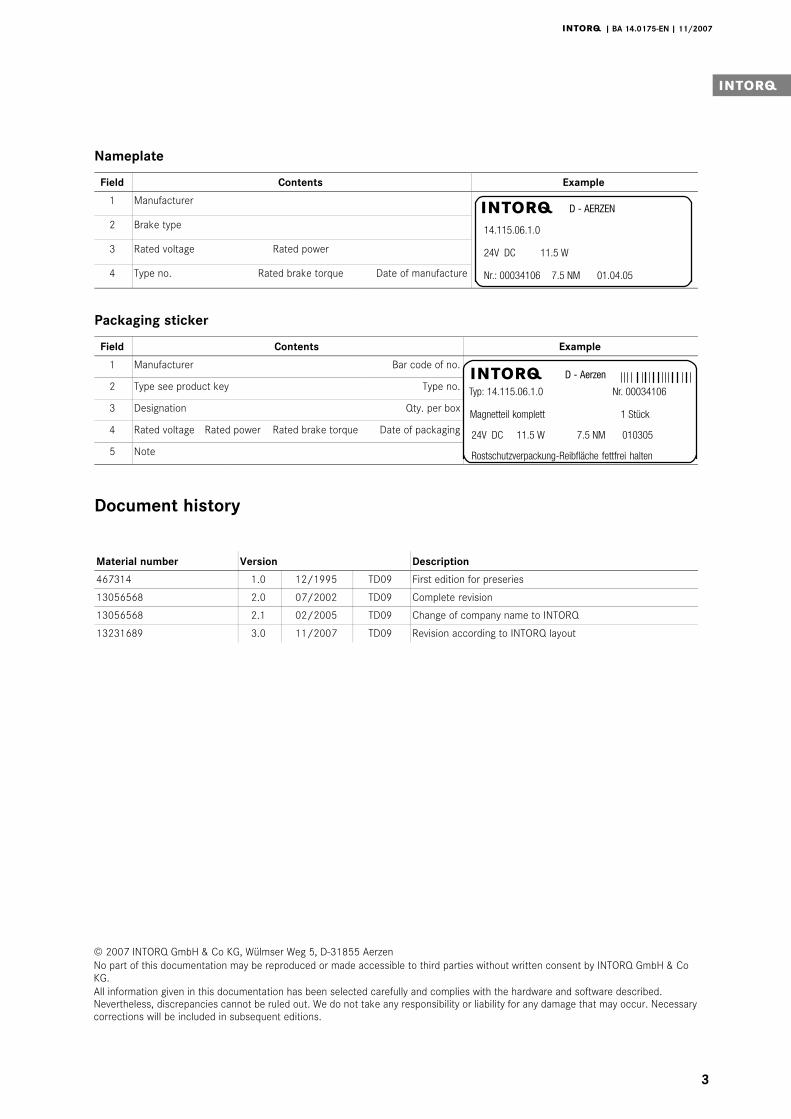
Nameplate
Field Contents Example
1 Manufacturer
14.115.06.1.0
24V DC 11.5 W
Nr.: 00034106 7.5 NM 01.04.05
D − AERZENj
2 Brake type
3 Rated voltage Rated power
4 Type no. Rated brake torque Date of manufacture
Packaging sticker
Field Contents Example
1 Manufacturer Bar code of no.D − Aerzen
Typ: 14.115.06.1.0 Nr. 00034106
24V DC 11.5 W 7.5 NM 010305
Rostschutzverpackung−Reibfläche fettfrei halten
Magnetteil komplett 1 Stück
j2 Type see product key Type no.
3 Designation Qty. per box
4 Rated voltage Rated power Rated brake torque Date of packaging
5 Note
Document history
Material number Version Description
467314 1.0 12/1995 TD09 First edition for preseries
13056568 2.0 07/2002 TD09 Complete revision
13056568 2.1 02/2005 TD09 Change of company name to INTORQ
13231689 3.0 11/2007 TD09 Revision according to INTORQ layout
0Fig. 0Tab. 0
© 2007 INTORQ GmbH & Co KG, Wülmser Weg 5, D−31855 Aerzen
No part of this documentation may be reproduced or made accessible to third parties without written consent by INTORQ GmbH & Co
KG.
All information given in this documentation has been selected carefully and complies with the hardware and software described.Nevertheless, discrepancies cannot be ruled out. We do not take any responsibility or liability for any damage that may occur. Necessary
corrections will be included in subsequent editions.
Contentsi
j | BA 14.0175−EN | 11/2007
4
1 Preface and general information 5 . . . . . . . . . . . . . . . . . . . . . . . . . . . . . . . . . . . . . . .
1.1 How to use these Operating Instructions 5 . . . . . . . . . . . . . . . . . . . . . . . . . . . . . . .
1.2 Terminology used 5 . . . . . . . . . . . . . . . . . . . . . . . . . . . . . . . . . . . . . . . . . . . . . . . . .
1.3 Scope of supply 5 . . . . . . . . . . . . . . . . . . . . . . . . . . . . . . . . . . . . . . . . . . . . . . . . . .
1.4 Labelling 6 . . . . . . . . . . . . . . . . . . . . . . . . . . . . . . . . . . . . . . . . . . . . . . . . . . . . . . . .
1.5 Legal regulations 6 . . . . . . . . . . . . . . . . . . . . . . . . . . . . . . . . . . . . . . . . . . . . . . . . .
2 Safety instructions 7 . . . . . . . . . . . . . . . . . . . . . . . . . . . . . . . . . . . . . . . . . . . . . . . . . . .
2.1 General safety information 7 . . . . . . . . . . . . . . . . . . . . . . . . . . . . . . . . . . . . . . . . . .
2.2 Definition of notes used 10 . . . . . . . . . . . . . . . . . . . . . . . . . . . . . . . . . . . . . . . . . . . .
3 Technical data 11 . . . . . . . . . . . . . . . . . . . . . . . . . . . . . . . . . . . . . . . . . . . . . . . . . . . . . . .
3.1 Product description 11 . . . . . . . . . . . . . . . . . . . . . . . . . . . . . . . . . . . . . . . . . . . . . . .
3.2 Selection table of clutches 14 . . . . . . . . . . . . . . . . . . . . . . . . . . . . . . . . . . . . . . . . .
3.3 Selection table of brakes 14 . . . . . . . . . . . . . . . . . . . . . . . . . . . . . . . . . . . . . . . . . . .
4 Mechanical installation 15 . . . . . . . . . . . . . . . . . . . . . . . . . . . . . . . . . . . . . . . . . . . . . . . .
4.1 Preparation 15 . . . . . . . . . . . . . . . . . . . . . . . . . . . . . . . . . . . . . . . . . . . . . . . . . . . . . .
4.2 Mounting 17 . . . . . . . . . . . . . . . . . . . . . . . . . . . . . . . . . . . . . . . . . . . . . . . . . . . . . . .
5 Electrical installation 20 . . . . . . . . . . . . . . . . . . . . . . . . . . . . . . . . . . . . . . . . . . . . . . . . .
6 Maintenance 21 . . . . . . . . . . . . . . . . . . . . . . . . . . . . . . . . . . . . . . . . . . . . . . . . . . . . . . . . .
6.1 Dismounting 21 . . . . . . . . . . . . . . . . . . . . . . . . . . . . . . . . . . . . . . . . . . . . . . . . . . . . .
6.2 Spare−parts list 22 . . . . . . . . . . . . . . . . . . . . . . . . . . . . . . . . . . . . . . . . . . . . . . . . . .
6.3 Spare parts order 23 . . . . . . . . . . . . . . . . . . . . . . . . . . . . . . . . . . . . . . . . . . . . . . . .

Preface and general information1 i
j | BA 14.0175−EN | 11/2007
5
1 Preface and general information
1.1 How to use these Operating Instructions
| These Operating Instructions inform about safety−relevant working on and with
electromagnetic clutches and brakes. They contain safety information which must be
observed.
| All persons working on or with the electromagnetic clutches and brakes must have
these Operating Instructions available and observe the information and notes relevant
for them.
| The Operating Instructions must always be in a complete and perfectly readable state.
1.2 Terminology used
Term In the following text used for
Clutches and brakes Electromagnetic clutches and brakes
Drive system Drive systems with electromagnetic clutches and brakes and other drive
components
1.3 Scope of supply
| The drive systems are combined individually according to a modular design. The scope
of delivery is indicated in the accompanying papers.
| After receipt of the delivery, check immediately whether it corresponds to the
accompanying papers. INTORQ does not grant any warranty for deficiencies claimed
subsequently. Claim
– visible transport damage immediately to the forwarder.
– visible deficiencies / incompleteness immediately to INTORQ GmbH & Co.KG.

Preface and general information1
j | BA 14.0175−EN | 11/2007
6
1.4 Labelling
Drive systems and drive components are clearly labelled and defined by the indications on the
nameplates.
Manufacturer: INTORQ GmbH & Co KG, Wülmser Weg 5, D−31855 Aerzen
| The INTORQ electromagnetic clutches and brakes are also available as individual
components. The user can combine them as desired. The following indications:
packaging sticker, nameplate, and type code are valid for the stator.
| If individual parts are supplied, there is no identification.
1.5 Legal regulations
Liability
| The information, data and notes in these Operating Instructions met the state of the
art at the time of printing. Claims referring to drive systems which have already been
supplied cannot be derived from the information, illustrations and descriptions.
| We do not accept any liability for damage and operating interference caused by:
– inappropriate use
– unauthorised modifications to the drive system
– improper working on and with the drive system
– operating faults
– disregarding these Operating Instructions
Warranty
| Terms of warranty: see terms of sale and delivery of INTORQ GmbH & Co. KG.
| Warranty claims must be made to INTORQ immediately after detecting defects or
faults.
| The warranty is void in all cases where liability claims cannot be made.

Safety instructions2 i
j | BA 14.0175−EN | 11/2007
7
2 Safety instructions
2.1 General safety information
| These safety notes do not claim to be complete. If any questions or problems occur,
please contact INTORQ GmbH & Co. KG.
| The clutches and brakes met the state of the art at the time of delivery and are
generally safe to operate.
| Clutches and brakes endanger persons, the clutches and brakes themselves and other
properties of the user if
– unqualified personnel work on and with clutches and brakes.
– the clutches and brakes are used for a purpose other than intended.
| The clutches and brakes must be designed such that they perform their function and
do not cause danger for persons if they are installed correctly and used as intended in
error−free operation. This also applies to clutches and brakes integrated into a drive
system.
| Take appropriate measures to ensure that the failure of the clutches or brakes will not
lead to damage to material.
| Do not operate the clutches and brakes unless they are in perfect condition.
| Retrofittings, modifications and changes of the drive system are generally forbidden. In
any case, INTORQ GmbH & Co. KG must be contacted beforehand.
| The friction lining and the friction surfaces must by no means have contact to oil or
grease since even small amounts reduce the brake torque considerably.
| Enclosure IP44, temperature class B (130°C).

Safety instructions2
j | BA 14.0175−EN | 11/2007
8
2.1.1 Personnel responsible for safety
Operators
| An operator is any natural or legal person who uses the clutch or brake or on whose
behalf the clutch or brake is used.
| The operator or his safety personnel must ensure
– that all relevant regulations, notes and laws will be maintained,
– that only qualified personnel work on and with the drive system,
– that the Operating Instructions are always available to the personnel working on and
with the clutch or brake,
– that unqualified personnel will not be allowed to work on and with the clutch or
brake.
Skilled personnel
Skilled personnel are persons who − because of their education, experience, instructions, and
knowledge about corresponding standards and regulations, rules for the prevention of
accidents, and operating conditions − are authorised by the person responsible for the safety
of the plant to perform the required actions and who are able to recognise potential hazards.
(See IEC 364, definition of skilled personnel)
2.1.2 Application as directed
| Drive systems
– are intended for use in machinery and systems.
– must only be used for the purposes ordered and confirmed.
– must only be operated under the ambient conditions prescribed in these Operating
Instructions.
– must not be operated beyond their corresponding power limits.
Any other use shall be deemed inappropriate!

Safety instructions2 i
j | BA 14.0175−EN | 11/2007
9
Application range of the INTORQ clutches and brakes
| No explosive or aggressive atmosphere.
| Humidity, no restrictions.
| Ambient temperature −20°C to +40°C.
| With high humidity and low temperatures
– Take measures to protect armature plate and rotor from freezing.
| Protect electrical connections against contact.
| Sparking in switching operation
– Especially at high speeds and high surface speeds of large clutches and brakes,
sparking can occur during the switch−on slip phase. This is a completely normal
phenomenon of pole face clutches and brakes. If necessary, insulate the drive
system depending on the ambient conditions.

Safety instructions2
j | BA 14.0175−EN | 11/2007
10
2.2 Definition of notes used
The following pictographs and signal words are used in this documentation to indicate dangers
and important information:
Safety instructions
Structure of safety instructions:
Danger!
Characterises the type and severity of danger
Note
Describes the danger
Possible consequences:
| List of possible consequences if the safety instructions are disregarded.
Protective measure:
| List of protective measures to avoid the danger.
Pictograph and signal word Meaning
Danger!Danger of personal injury through dangerous electrical voltage
Reference to an imminent danger that may result in death or serious
personal injury if the corresponding measures are not taken.
Danger!Danger of personal injury through a general source of danger
Reference to an imminent danger that may result in death or serious
personal injury if the corresponding measures are not taken.
� Stop!Danger of property damage
Reference to a possible danger that may result in property damage if the
corresponding measures are not taken.
Application notes
Pictograph and signal word Meaning
� Note! Important note to ensure troublefree operation
Tip! Useful tip for simple handling
� Reference to another documentation

Technical data3 i
j | BA 14.0175−EN | 11/2007
11
3 Technical data
3.1 Product description
3.1.1 Flange−mounted clutches
The clutch consists of the stator (1) with encapsulated coil, the rotor (2) with fixed friction
lining and an armature assembly (5, 6, 7) with armature plate and prestressed spring. The
stator (1) is centred to the shaft and mounted at the machine panel. The rotor (2) is connected
to the shaft using a key. Design 1.5 is particularly suitable for through−shafts. The magnetic
field which is created when a DC voltage is applied attracts the armature plate against the
friction face of the rotor (2) via the air gap �sair�. The torque is transmitted without backlash
by the spring. The prestressed springs draw the armature plate back to its initial position when
the DC voltage is no longer applied. The clutch is released without residual torque.
sair 1
2
5,6,7
Fig. 1 Flange−mounted clutch INTORQ 14.105.��.1.1
1 Stator 5,6,7 Armature assembly
2 Rotor

Technical data3
j | BA 14.0175−EN | 11/2007
12
3.1.2 Shaft−mounted clutches
The stator (1) with encapsulated coil and sealed deep−groove ball bearing is secured against
torsion by a torque arm engaging into the lug at the stator. The torque arm must only accept
the bearing friction. A circlip holds the stator (1) on the rotor (2) in axial direction. At the same
time, the rotor (2) with fixed friction lining must be mounted onto the shaft. Centrings are not
necessary. If a DC voltage is applied the armature plate of the armature assembly (5, 6, 7) is
attracted against the friction surface of the rotor (2) by the magnetic field. The torque is
transmitted without backlash. When the DC voltage is switched off, the prestressed spring
pulls the armature plate back to its initial position. It is released without residual torque.
sair 1
2
5,6,7
Fig. 2 Shaft−mounted clutch INTORQ 14.105.��.3.1
1 Stator 5,6,7 Armature assembly
2 Rotor

Technical data3 i
j | BA 14.0175−EN | 11/2007
13
3.1.3 Flange−mounted brakes
The brake consists of the stator (1) with encapsulated coil and fixed friction lining and an
armature assembly (5, 6, 7) with armature plate and prestressed spring. The stator (1) is
centred to the shaft and mounted at the machine panel. The armature assembly (5) is
connected to the shaft to be braked. If a DC voltage is applied the armature plate is attracted
via the air gap �sair� against the friction surface of the stator (1) by the magnetic field. The shaft
is braked by friction locking. When the DC voltage is switched off the prestressed patented
spring pulls the armature plate back to its initial position. The brake is released without
residual torque.
sair1
5, 6, 7
Fig. 3 Flange−mounted brake INTORQ 14.115.��.1.1
1 Stator 5,6,7 Armature assembly

Technical data3
j | BA 14.0175−EN | 11/2007
14
3.2 Selection table of clutches
Type Mr 1)
[Nm]nmax
[ i 1]P20°C
[W]Operating times 2)
[ms]QE [J] QNA
[kWh]Sfo
[h−1]J [10−5 kgm2]max
[min−1]Rotor Armature plate
t11 t12 t1 t2 1 3 1/2 3 5
INTORQ 14.105.06. 7.5 8000 15 15 30 45 10 3.6x10³ 10 72 11.9 13.3 6 4.2 9.2
INTORQ 14.105.08. 15 6000 20 20 55 75 15 6x10³ 16.6 56 26.5 29.4 17.1 11.8 28.2
INTORQ 14.105.10. 30 5000 28 25 85 110 25 10x103 34.7 43 78 86.6 66.4 47.2 92
INTORQ 14.105.12. 60 4000 35 35 105 140 40 16x103 69.5 37 226 246 180 130 258
INTORQ 14.105.16. 120 3000 50 45 125 170 50 25x103 130.5 36 630 690 633.3 480 868
INTORQ 14.105.20. 240 3000 68 60 140 200 60 40x103 277.7 28 2050 2150 1900 1370 2580
INTORQ 14.105.25. 480 2000 85 75 155 230 70 65x103 555.5 22 5470 5660 4800 3580 7200
1) Referred to relative speed n = 100 min−1
2) Average values for switching on the DC side with rated air gap and warm coilStandard voltage 24 V +5% / −10% acc. to VDE0580Temperature class B (130°C)
3.3 Selection table of brakes
Type Mr 1)
[Nm]nmax
[min−1]P20°C
[W]Operating times 2)
[ms]QE [J] QNA
[kWh]Sfo [h−1] J [10−5
kgm2][ ]
Armatureplate
t11 t12 t1 t2 1/2 3
INTORQ 14.115.06. 7.5 8000 11.5 10 20 35 10 3.6x10³ 10 72 6 4.2
INTORQ 14.115.08. 15 6000 16 15 25 40 20 6x10³ 16.6 56 17.1 11.8
INTORQ 14.115.10. 30 5000 21 20 40 60 30 10x103 34.7 43 66.4 47.2
INTORQ 14.115.12. 60 4000 28 25 55 80 45 16x103 69.5 37 180 130
INTORQ 14.115.16. 120 3000 38 30 70 100 60 25x103 130.5 36 633.3 480
INTORQ 14.115.20. 240 3000 45 35 80 115 70 40x103 277.7 28 1900 1370
INTORQ 14.115.25. 480 2000 70 40 90 130 80 65x103 555.5 22 4800 3580
1) Referred to relative speed n = 100 min−1
2) Average values for switching on the DC side with rated air gap and warm coilStandard voltage 24 V +5% / −10% acc. to VDE0580Temperature class B (130°C)
Mechanical installation4 i
j | BA 14.0175−EN | 11/2007
15
4 Mechanical installation
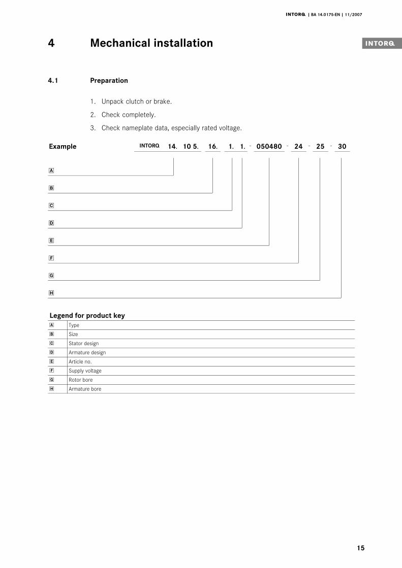
4.1 Preparation
1. Unpack clutch or brake.
2. Check completely.
3. Check nameplate data, especially rated voltage.
Example INTORQ 14. 10 5. 16. 1. 1.
− 050480 − 24 − 25 − 30
�
�
�
�
�
�
�
�
Legend for product key
� Type
� Size
� Stator design
� Armature design
� Article no.
� Supply voltage
� Rotor bore
� Armature bore

Mechanical installation4
j | BA 14.0175−EN | 11/2007
16
4.1.1 Designs
INTORQ 14.105.��.
INTORQ 14.105.��.
INTORQ 14.105.��.
INTORQ 14.105.��.
INTORQ 14.105.��.
INTORQ 14.105.��.
1.1
1.3
1.5
3.1
3.3
3.5
Item 1; 2; 5
Item 1; 2; 6
Item 1; 2; 7
Item 3a; 3b; 5
Item 3a; 3b; 6
Item 3a; 3b; 7
INTORQ 14.115.��.
INTORQ 14.115.��.
INTORQ 14.115.��.
1.1
1.2
1.3
Item 4; 5
Item 4; 8
Item 4; 6
Size
Stator design
Armature design
7 6 5 2 1
7 6 5 3b 3a
8 5 46

Mechanical installation4 i
j | BA 14.0175−EN | 11/2007
17
4.2 Mounting
� Stop!
| Keep friction faces free of grease and oil!
| Use oil− and grease−tight deep−groove ball bearings only!
4.2.1 Clutch and brake of design 1
The stator of clutch or brake of design 1 must be mounted internally or externally centred
(observe dimension �tk for max. centricity from Tab. 1 ). The mounting surface should not
exceed a maximum phase run−out �x" (Tab. 1) and should not be convex. In the case of
internal centring, the register diameter is machined to an oval clearance.
� Stop!
The rotor must be secured axially!
Fig. 4 Internal centring External centring
4.2.2 Stator design 3
The stator design 3 does not need a mounting surface as the centring is performed by a
deep−groove ball bearing on the rotor. A torque arm must be provided for the bearing
friction. This torque arm engages in the recess of the anti−rotation tag.
� Stop!
The stator must not be strained in any case!

Mechanical installation4
j | BA 14.0175−EN | 11/2007
18
4.2.3 Mounting of armature assembly of designs 1, 2 and 5
The armature assembly is shifted onto the shaft. The maximum permissible centre offset of
the shafts, dimension "tw" can be obtained from Tab. 1. The air gap �sair" (Tab. 1) must be
adjusted using a feeler gauge.
Use shims for the exact air gap setting and for the compensation of wear.
� Stop!
The armature assembly must be fixed axially.
14.105 14.115
sairsair
Fig. 5
Size sair x INTORQ 14.105 INTORQ 14.115
[mm] [mm] tk tw b [mm] tw b [mm]
06 0.2�0.05 0.04 0.2 0.1 24 0.16 18
08 0.2�0.05 0.05 0.3 0.1 26.5 0.16 20
10 0.2�0.05 0.06 0.3 0.1 30 0.16 22
12 0.3�0.1 0.07 0.3 0.1 33.5 0.2 24
16 0.3�0.1 0.09 0.4 0.2 37.5 0.2 26
20 0.5�0.15 0.11 0.4 0.2 44 0.2 30
25 0.5�0.15 0.14 0.5 0.2 51 0.3 35
Tab. 1

Mechanical installation4 i
j | BA 14.0175−EN | 11/2007
19
4.2.4 Mounting of armature assembly of design 3
Size Screws DIN Schnorr lock washer * � d [mm] t [mm]
06 M3x8 84 Schnorr lock washer 3 3.1 0.8
08 M4x10 84 Schnorr lock washer 4 4.1 1.0
10 M5x12 6912 Schnorr lock washer 5 5.1 3.5
12 M6x16 7984 Schnorr lock washer 6 6.1 2.8
16 M8x20 7984 Schnorr lock washer 8 8.2 3.5
20 M10x25 7984 Schnorr lock washer 10 10.2 3.5
25 M12x25 7984 Schnorr lock washer 12 12.2 3.8
Tab. 2
* Source of supply:Adolf Schnorr GmbH & CO KGPostfach 60 0162; D−71050 SindelfingenPhone: ++49 (0)7031−3020; Fax: ++49(0)7031−382600
12
3
4
5
d
t
1 Mounting surface 4 Prestressed spring
2 Armature plate 5 Lock washer
3 Screw

Electrical installation5
j | BA 14.0175−EN | 11/2007
20
5 Electrical installation
The device is connected to DC voltage (observe voltage specification on the stator).
Permissible voltage fluctuation according to VDE 0580: +6% to −10%.
The standard voltage is 24V DC. If no DC voltage is available the voltage must be supplied
via transformers or rectifiers.
The clutches and brakes should be switched on the DC side to achieve short switch−off
times.
secondary
primary
230V ~ 50Hz230V ~ 50Hz
Univ
ersa
l sp
ark
suppre
ssor
14.1
98.0
0.0
1 ... 0
4
Fig. 6 Switching on the DC side Switching on the AC side
When switching on the DC side, use a spark suppressor to protect coil and contacts from
excessive inductive voltages.
� Stop!
If there is no protective circuit the inductive voltage can be higher than the
values specified in VDE 0580 and cause the coil to fail which destroys the
switching contacts.
The spark suppressor consists of a non−inductive pulse capacitor which accepts current
peaks during switching. When a spark suppressor is used, the spark at the contact and
thus the contact erosion is considerably reduced.

Maintenance6 i
j | BA 14.0175−EN | 11/2007
21
6 Maintenance
The INTORQ clutches and brakes are largely free of maintenance. In applications requiring
many switching operations the air gap �sair" must be checked and readjusted at certain
periods. When the air gap has reached 250 % of its rated value �sair" it must be readjusted
to the rated value at the latest.
| For air gap setting �sair" after wear, see chapter 6.1, Dismounting.
| The shims mentioned in section 2 can be removed or the spacers can be reduced.
The friction face poles of the rotor or stator of clutches or brakes run into the armature
plate. Friction marks are thus normal and must not be re−worked!
� Stop!
Friction faces must be kept absolutely free of oil and grease!
6.1 Dismounting
Remove the axial circlip or shaft locking plate Fig. 7 to disassemble the armature assembly
of design 1 or 2 or the rotor. After that the armature assembly can be withdrawn from the
shaft via the withdrawal thread �d" (see Fig. 7 and Tab. 3) provided for disassembly in the
flange hub or rotor of the corresponding part. After the armature assembly has been
withdrawn, remove the shims depending on the air gap size �sair" (Fig. 5 and Tab. 1) and
mount them afterwards between circlip and flange hub.
d
e
d
c
Shims
1
Fig. 7
Dimensions Size
06 08 10 12 16 20 25
� c 29 36 46 56 73 92 114
� e 31 37 47 56 73 93 120
d M4 M4 M4 M4 M5 M6 M8
d1 M5 M5 M5 M6 M8 M8 M10
Tab. 3 Dimensions in mm

Maintenance6
j | BA 14.0175−EN | 11/2007
22
6.2 Spare−parts list
The clutches and brakes have a wear reserve of several millimeters. When these are used up
after several readjustments, the rotor and armature assembly of clutches and the stator and
armature assembly of brakes must be replaced in pairs.
| When ordering spare parts, indicate the designation of the parts according to the
illustration and list below.
3 1
2
10
5 6 7
11
12 11
14 13 15
4
5
10
8 6
Item Designation Item Designation
1 Clutch−stator design 1 8 Armature assembly design 2
2 Rotor design 1 10 Setscrew
3 Clutch − stator + rotor 11 Deep−groove ball bearing 2RS
4 Brake − stator 14.115 12 Spacer
5 Armature assembly design 1 13 Circlip
6 Armature assembly design 3 14 Key
7 Armature assembly design 5 15 Spring ring

Maintenance6 i
j | BA 14.0175−EN | 11/2007
23
6.3 Spare parts order
Example: Electromagnetic clutch INTORQ 14.105 10. Item 1 − 24 V / 28W
Type
Size
Spare part
Example: Electromagnetic brake INTORQ 14.115 16. Item 6
Type
Size
Spare part
| When you order stators, you also have to indicate the coil voltage and power (see
section Electrical connection).
| When ordering rotors and armature assemblies of designs 1 and 2, also specify the
bore diameter.
INTORQ ˘
Sales and Service
around the world
INTORQ customers can reach us at
any time and from anywhere in the
world. Our Key Account Sales Team
looks after key account customers
and project business.
In addition, we co−operate with
Lenze’s global sales organisation.
You can contact us via Lenze Service
by calling the 24−hour helpline
(008000 24 46177).
INTORQ GmbH & Co KG
Postfach 1103
D−31849 Aerzen
Wülmser Weg 5
D−31855 Aerzen
Tel.: +49�(0)�5154 70534-0
Fax: +49�(0)�5154 70534-200
E−Mail [email protected]
www.intorq.de
setting the standard
www.intorq.de
j
13
23
16
89
|
BA
14
.01
75
−EN
|
|
3.0
|
©1
1.2
00
7
|
TD
09
|
10
9
8
7
6
5
4
3
2
1