Ome44376d Vr3000 Mainte Cof%26amp%3bmol
57
INSTRUCTION MANUAL VDR MAINTENANCE VIEWER Model VR-3000/VR-3000S APPLICABLE TO SOFTWARE VERSION 1.5x/1.6x This manual is solely for use by the i nstaller . Under no circumstances shall this manual be released to the user . The installer shall remove this manual from the vessel after installation. This manual contains no password data. Obtain password data from FURUNO before beginning the installation. www.furuno.com
-
Upload
edwin-nyange -
Category
Documents
-
view
228 -
download
0
Transcript of Ome44376d Vr3000 Mainte Cof%26amp%3bmol
8102019 Ome44376d Vr3000 Mainte Cof26amp3bmol
httpslidepdfcomreaderfullome44376d-vr3000-mainte-cof26amp3bmol 157
INSTRUCTION MANUAL
VDR MAINTENANCE VIEWER
Model VR-3000VR-3000SAPPLICABLE TO SOFTWARE VERSION 15x16x
This manual is solely for use by the installer Under nocircumstances shall this manual be released to the user
The installer shall remove this manual from the vessel after
installation
This manual contains no password data Obtain password data
from FURUNO before beginning the installation
wwwfurunocom
8102019 Ome44376d Vr3000 Mainte Cof26amp3bmol
httpslidepdfcomreaderfullome44376d-vr3000-mainte-cof26amp3bmol 257
983124983144983141 983152983137983152983141983154 983157983155983141983140 983145983150 983156983144983145983155 983149983137983150983157983137983148
983145983155 983141983148983141983149983141983150983156983137983148 983139983144983148983151983154983145983150983141 983142983154983141983141983086
983110983125983122983125983118983119 983105983157983156983144983151983154983145983162983141983140 983108983145983155983156983154983145983138983157983156983151983154983087983108983141983137983148983141983154
983097983085983093983090 983105983155983144983145983144983137983154983137983085983139983144983151
983118983145983155983144983145983150983151983149983145983161983137 983094983094983090983085983096983093983096983088 983114983105983120983105983118
983105 983098 983123983109983120 983090983088983089983088983086983120983154983145983150983156983141983140 983145983150 983114983137983152983137983150983105983148983148 983154983145983143983144983156983155 983154983141983155983141983154983158983141983140983086
983108 983098 983110983109983106983086 983089983091983084 983090983088983089983092
983120983157983138983086 983118983151983086 983119983117983109983085983092983092983091983095983094983085983108
983080983122983109983110983125 983081 983126983122983085983091983088983088983088983087983123 983107983119983110983078983117983119983116
983088 983088 983088 983089 983095 983092 983092 983089 983092 983089 983091
8102019 Ome44376d Vr3000 Mainte Cof26amp3bmol
httpslidepdfcomreaderfullome44376d-vr3000-mainte-cof26amp3bmol 357
1
CONTENTS
1 HOW TO INSTALL THE VDR MAINTENANCE VIEWER CONNECT THE PC 3
11 Installation by CD (supplied) 3
12 Installation in a Windows 7 PC (32 bit only) 3
13 How to set the PC 4
14 How to connect a PC to the VR-3000 5
15 How to start the VDR Maintenance Viewer 5
16 How to uninstall the VDR Maintenance Viewer 5
2 SOFTWARE CONFIGURATION 6
21 Preparing the software setup 6
22 Radar 8
23 Serial Signal 15
24 Analog Signal 17
25 Digital Signal 19
26 Audio 21
27 Alarm 24
28 Event 26
29 Hardware 27
210 JB 28
211 Life Time 29
212 Network 30
213 System 31
214 Software 32
215 GPS 34
216 Vessel 35
217 Delivery 36
3 HOW TO BACK UP CONFIGURATION DATA 37
31 How to Back up Configuration Data to the Startup Compact Flash (CF) 37
32 How to Back up Configuration Data to a PC 38
33 How to restore the default settings 38
4 HOW TO UPLOAD CONFIGURATION DATA FROM A PC 39
5 MEDIA MANAGEMENT 40
51 Initialization 40
52 Creation 43
53 How to Enable Recording Area on the Backup HDD 45
6 OTHER FUNCTIONS 46
61 Software Management 46
62 Password Management 47
63 Record Comparison 48
64 Software History 49
65 Easy Setup 50
66 Equipment Management 51
67 PC_RAP 52
68 Other 54
8102019 Ome44376d Vr3000 Mainte Cof26amp3bmol
httpslidepdfcomreaderfullome44376d-vr3000-mainte-cof26amp3bmol 457
2
This manual describes how to set the VR-3000VR-3000S after installation The outline of
the setup is as below
Step 1 Network setting on PC and VDR
Step 2 Software setting
Step 3 Backup data setting
Step 4 Software configuration from file data
Step 5 Media management
Step 6 Other functions
After setting up make a backup copy of configuration data onto the CompactFlash (CF)
and the PC
Parts and Equipment needed
a) PC with Internet Explorer 60
b) Ethernet cross cable
8102019 Ome44376d Vr3000 Mainte Cof26amp3bmol
httpslidepdfcomreaderfullome44376d-vr3000-mainte-cof26amp3bmol 557
3
1 How to Install the VDR MaintenanceViewer Connect the PC
11 Installation by CD (supplied)
Live Player V4 and the VDR Maintenance Viewer Program are included in the accessory
CD Install these programs in the PC
1 Place the CD in the PC CD drive
2 The contents of the CD are displayed in a window Double click on the file ldquoviewexerdquoThe Installation Wizard opens
3 Follow the directions of the Installation Wizard
The Live Player V4 and Maintenance Viewer are installed in the computer The Live
Player V4 is not required for use here
12 Installation in a Windows 7 PC (32 bit only)
This section provides the procedure for the installation of the VDR Maintenance Viewer ina Windows 7 PC
Deactivate the firewall
Temporarily deactivate the Windows 7 firewall to install and operate the VDR
Maintenance Viewer
1 Open the Control Panel
2 Select Network and Internet
3 Select Network and Sharing Center
4 Select Windows Firewall from the left window
5 Select Turn Windows Firewall on or off from the left window
6 At Public network location settings select Turn off Windows Firewall (notrecommended) then click the OK button
If you try to use the VDR Maintenance Viewer with the firewall active the following
occurs
bull VDR settings cannot be downloaded when the Live Player V4 is connected
bull Data cannot be replayed when the Backup HDD is connected to LAN Data extraction
and analysis also are not possible
bull VDR settings cannot be downloaded or updated from the VDR Maintenance Viewer
To reactivate the firewall select Turn on Windows firewall at step 6 in the procedure
8102019 Ome44376d Vr3000 Mainte Cof26amp3bmol
httpslidepdfcomreaderfullome44376d-vr3000-mainte-cof26amp3bmol 657
4
How to grant administrator rights
Run the VDR Maintenance Viewer program as an Administrator to install it
1 Click the Start button select All Programs and check that VR-3000 appears
2 Select LivePlayerV4 at VR-3000 right click then select Properties
3 Select Compatibility from the Live Player V4 Properties dialog box
4 At Privilege Level check Run this program as an administrator
5 Select MaintenanceViewer at VR-3000 right click then select Properties
6 Select Compatibility from the menu in the MaintenanceViewer Properties dialogbox
7 At Privilege Level check Run this program as an administrator then click the OK button
How to install the VDR Maintenance Viewer software
1 Double click VR-3000_verexe ( is version number)2 The Setup ndash VR-3000 dialog box appears click the Next button
3 Confirm that the install location is CProgram Files then click the Next button
4 The Folder Exists dialog box appears click the Yes button
5 After the Folder Exists dialog box disappears click the Next and Install buttons
6 After the installation is completed the message Yes restart computer now ischecked then click the Finish button
13 How to set the PC
Before connecting to VR-3000VR-3000S set the IP address and subnet mask of the PC
as below The IP address of VR-3000VR-3000S is 1000100
Windows XP
1 Click Start Settings Control Panel and Network Connections
2 Click Local Window Network Properties and Internet Protocol (TCPIP)
3 Click the Properties button
4 Choose ldquoUse the following addressrdquo
5 Enter IP address and subnet mask
IP address 1000102 or 100099 (other than 1000100)
Subnet mask 255000
6 Click the OK button and then click it again
Windows Vista
1 Click Start Control Panel Network and Internet Network and Sharing Center
2 Click View status to show the Local Window Connection Status dialog box and clickthe Properties button
3 Select Internet Protocol Version 4 (TCPIP v4) and click the Properties button
4 Select Use the following IP address and enter IP address and subnet maskIP address 1000102 or 100099 (other than 1000100)Subnet mask 255000
5 Click the OK button and then click it again on the next screen
6 Restart the PC
8102019 Ome44376d Vr3000 Mainte Cof26amp3bmol
httpslidepdfcomreaderfullome44376d-vr3000-mainte-cof26amp3bmol 757
5
Windows 7
1 Click Start Control Panel Network and Internet Network and Sharing Center
2 Click the Properties button on the Local Area Connection Status dialog box
3 Select Internet Protocol Version 4 (TCPIP v4) then click the Properties button
4 Click the Use the following IP address button
5 Enter IP address and subnet mask
IP address 1000102 or 100099 (other than 1000100)Subnet mask 255000
6 Click the OK button and then click the Close button
7 Restart the PC
14 How to connect a PC to the VR-3000
Use an Ethernet cross cable to connect a PC to J14 (DATA) in the DCU
Ethernetcross cable
DCU
PC
J14 (DATA)
15 How to start the VDR Maintenance Viewer
Windows XP START menu gt VR-3000 gt VDR Maintenance Viewer
Windows Vista START menu gt All Programs gt VR-3000 gt VDR Maintenance Viewer
Windows 7 START menu gt All Programs gt VR-3000 gt VDR Maintenance Viewer
16 How to uninstall the VDR Maintenance ViewerUninstall the software as an Administrator
For Windows XP
1 Click START menu gt VR-3000 gt VR-3000 Uninstall
Uninstall the software following the wizard shown on the display
2 Delete the VDRViewer folder saved in the My Computer gt Local Disk (C) gt Program Files
folder
For Windows Vista or Windows 7
1 Click START menu gt All Programs gt VR-3000 gt VR-3000 UninstallUninstall the software following the wizard shown on the display
2 Delete the VDRViewer folder saved in the My Computer gt Local Disk (C) gt Program Files
folder
8102019 Ome44376d Vr3000 Mainte Cof26amp3bmol
httpslidepdfcomreaderfullome44376d-vr3000-mainte-cof26amp3bmol 857
6
2 Software ConfigurationDisconnect the Remote Alarm Panel until the software configuration is completed
otherwise an alarm (grabber failure or no radar video) sounds
Procedure
1 In the Maintenance Viewer log in to Serviceman2 Download the configuration data from the VDR into the Maintenance Viewer
3 Set each tab (Refer from section 22 for further explanation)
4 After each tab has been set up save the data to the VDR
5 Lastly click the write button to backup the set data to the DRU Backup HDD and the CF
21 Preparing the software setup
To configure VR-3000VR-3000S software with the VDR Maintenance Viewer do the
following
1 Make sure that the PC and DRU are connected securely to the DCU2 Turn on the VDR and wait about three minutes
3 Download ldquoequipxmlrdquo from the VDR to the PC using the following steps
1 Open Internet Explorer on the PC
2 Enter the URL ftp1000100pub to access the VDR from the PC
3 Copy the file ldquoequipxmlrdquo and paste it onto the PC desktop
4 Start the VDR Maintenance Viewer
5 Enter the IP address1000100 in the Maintenance Login dialog box
6 Checkmark ldquoServicemanrdquo enter the password and click the OK button
Note Do not release the password to unauthorized personnel
If the connection is successful the information shown below appears in the status
window- System Time - RAP LEDs - POWER STATUS- DRU Information - Backup HDD Information
If an error message appears the IP address or password may be wrong or the cable
between the PC and VDR is not correctly connected
7 Check the memory size of the DRU and Backup HDD that appear in the status
window
If the memory size display shows MB (data read error) restart the VDR If the
display still does not change check that the DRU and HDD are correctly connected
8102019 Ome44376d Vr3000 Mainte Cof26amp3bmol
httpslidepdfcomreaderfullome44376d-vr3000-mainte-cof26amp3bmol 957
7
Example of acceptable memory size displays
Backup HDD InformationSelected AREA2Size 37864 MB
6GB DRU InformationSelected DRUSize 5794 MB or more
9GB DRU InformationSelected DRUSize 8822 MB or more
8 Select PC_RAP from the Tool menu
Confirm Alarm box in PC_RAP When a 3xx error is displayed as above the data is not
input correctly Data settings are explained on the page 12 If error messages 094 098
018 022 etc are displayed remove the error before going to the next step Refer to the
VDR Operatorrsquos Manual or error code list for definitions of the meanings of individual
error codes
9 Click the X button at the top right corner to close the PC_RAP
10 From the menu select Maintenancegt Equipment Managementgt Import
11 Select the file ldquoequipxmlrdquo from the desktop and click [open]
12 From the menu select Maintenancegt VDR Config Managementgt Download Click
the OK button and then [Close]
If the configuration file has already been downloaded the 12th step is not necessary
The following explanation refers to setting individual tabs
On the signal tab there is an Information Area (left) and a Setting Area (right) Select the
channel to set in the Information Area on the left by selecting it with the cursor and then
set it in the Setting Area on the right The results of the updated setting are displayed in
the Information Area After setting each channel click SET to finish
8102019 Ome44376d Vr3000 Mainte Cof26amp3bmol
httpslidepdfcomreaderfullome44376d-vr3000-mainte-cof26amp3bmol 1057
8
22 RadarRadar Setup is performed in the Radar Tab
Equipment Setup
1 Click the Radar tab
The Radar information setup screen appears
2 Select a radar channel from the Information area For example click the CH No1 boxto open the corresponding setup
3 Click the Select Equipment button in the Setting Area The following dialogue boxappears
4 Select a radar model
For example as in the above illustration select Radargt RadarInterfacegtFurunogtFAR-28x7gt SXGA(60Hz) and click the OK button As in thefollowing illustration FAR-28x7 appears in the Type No field in the CH No 1 of theInformation Area Detailed information about the selected radar appears in the Setting Area
8102019 Ome44376d Vr3000 Mainte Cof26amp3bmol
httpslidepdfcomreaderfullome44376d-vr3000-mainte-cof26amp3bmol 1157
9
If your radar model is not in the list enter the required information manually Thesetting values are the same as the previous Web Configuration values
5 Click the Image Capture button in the Setting Area Confirm the correct video signal6 If required update the Setting Area item contents
It is not necessary to enter information very every item in the Setting Area For easyidentification of Input Source enter Equipment Category Brand Type No and DataName
7 Click the Set button to finish
8 To setup multiple radars repeat steps 2 through 7
9 Click the Check button in the setting area to perform radar check Results appear inthe Check section of the Information Area
8102019 Ome44376d Vr3000 Mainte Cof26amp3bmol
httpslidepdfcomreaderfullome44376d-vr3000-mainte-cof26amp3bmol 1257
10
To import the exact settings to another ship save the settings of the device in the Setting Area to the PC database
1 Click on Reflect Equipment
2 Copy the file to the PC by using Maintenancegt Equipment Managementgt Export inthe menu
3 Import to the other shiprsquos VDR from the PC
How to Set the Record Pattern
When there are two or more Radar units connected to the VDR select which radar torecord to
Note When using a 6 GB DRU it possible to record to 1 channel and when using a 9 GBDRU it is possible to record to 2 channels
1 In the Setting Area click the Recording Mode button The following dialogue boxappears
R1-R4 1st Radar (CH No1)~4
th Radar (CH No4)
G Records signal to the youngest radar number in a group pattern (ex R1-R4 aregrouped) If the youngest number is inactive signal is recorded to the next youngestnumber in sequence within the group
I Indicated unit recordssends
N Indicated unit does not recordsend
2 Select a recording pattern from Patterns 1-4
For example the settings in the above illustration are as follows
Recording Pattern 1 R1 signal is recorded to DRU R2 ndash R4 do not record
R1 and R2 signals are recorded to the Backup HDD R3ndashR4 donot record
Network Sending R1-R4 all send to network
Recording Pattern 3 Recording signal to the DRU automatically routes to the nextyoungest active number in the group between R1 and R3 R4 Does not recordExample If R1 is inactive signal is recorded to R2
Recording to Backup HDD Same as DRU
Send to Network R1-R4 all is sent to the network
3 Update I and N as needed
8102019 Ome44376d Vr3000 Mainte Cof26amp3bmol
httpslidepdfcomreaderfullome44376d-vr3000-mainte-cof26amp3bmol 1357
11
Place the cursor above either I or N and left click to alternate With this I is set torecord while N is set to not record G cannot be changed
4 After completing setup click the OK button
5 To record settings to the database click Reflect Equipment in the Setting Area
How to Enter Information Manually
This VDR system receives in VESA (Video Electronics Standards Association) signal Image signal 05-1Vpp (When using composite signal the minimum synchronization
signal is 50 mV)
Horizontal Synchronization Signal Max plusmn91146 kHz
Vertical Synchronization Signal Max 35 Hz
Acceptable Image Resolution 640x480 ndash 1280x1024
Channel number conforms to the number displayed by the DCU
To set the Radar tab do the following
1 Click the Radar tab
2 Choose the channel with the entered Radar Image from the Information Area
3 Check the Active box in the Setting Area and enter the Horizontal and Verticalresolution of the incoming image in the Horizontal resolution and Vertical resolutioncolumns
4 Click the Set button
5 Click the Image Capturehellip button The Image Capture dialogue box appears
6 Click the Test button in the Image Capture window Radar image appears a fewseconds later
7 If the image is normal close the Image Capture window8 Input each item in the Setting Area
8102019 Ome44376d Vr3000 Mainte Cof26amp3bmol
httpslidepdfcomreaderfullome44376d-vr3000-mainte-cof26amp3bmol 1457
12
Items are as follows
Active Check a channel to activate it
Brand Enter brand nameType No Enter type noCheck Set and activate checkData Name Enter data nameHorizontal resolution Set horizontal resolutionVertical resolution Set vertical resolutionHorizontal Offset Move the picture horizontallyVertical offset Move the picture verticallyPLL This sets the frequency of the PLL-oscillatorCDEV Set CDEV
VCOSL Set VCO Signal LeadPhase (0-63) Phase setting selects the phase of the sampling clock relativeto phase locked loop signal in 64 steps of 5625 degrees IfPhase is not set correctly any section of an image consistingof vertical lines may show line ldquotearingrdquo
Sync Type Select the type of video sync signalHorizontal sync polarity Set the polarity of the horizontal sync signalVertical sync polarity Set the polarity of the vertical sync signalHDVD Sync Termination Sets horizontal and vertical synchronization point When
using a composite signal set to 75ohmsPulse Width for VD Detection (0-1020 Step4) Sets the pulse width for video signal
detectionInterlace Type When the video image is interlace set ldquoInterlaceldquo sampling
mode In Interlace mode the even pixels are sampled on oneframe and odd pixels are sampled on the other frame
8102019 Ome44376d Vr3000 Mainte Cof26amp3bmol
httpslidepdfcomreaderfullome44376d-vr3000-mainte-cof26amp3bmol 1557
13
Interlace Polarity Set interlace polarityITRP (0-4092 Step4) Enter interlace pulse positionITRW (0-4092 step4) Enter interlace pulse widthSampling Rate Display sampling rate Fixed at ldquo15 secondsrdquoCompress Type (viewer) Set compress type (viewer)Color Bit Display and set Color BitChange Pump Current Set pump current Fixed at ldquo05 mArdquo
Video Clock Polarity Set video clock polarity Fixed at ldquoThroughrdquoCounter Clock SelectionSelect counter clock selection Fixed at ldquo49 MHzrdquoVCO Clock Hold Sets VCO clock holdRed Gain (0-255) Enter red gainGreen Gain (0-255) Enter green gainBlue Gain (0-255) Enter blue gainRed Offset (0-255) Enter red offsetGreen Offset (0-255) Enter green offsetBlue Offset (0-255) Enter blue offsetBlack Level (0-255) Enter black levelEquipment Category Enter equipment category
Board Name Enter board name for corresponding channelNote Enter note
Note Offset Phase and Color Bit change with the length of the antenna cable
Marked Items For easy identification of input source enter Equipment Category Brand
Type No and Data Name
Measurement BoxThe Measurement Box is located on the left side of the Information Area The LOWHorizontal and Vertical counter should be higher than the HIGH counter If reversely the
HIGH counter is higher than the LOW counter it is possible that the SYNC Polaritysettings are adjusted incorrectly
8102019 Ome44376d Vr3000 Mainte Cof26amp3bmol
httpslidepdfcomreaderfullome44376d-vr3000-mainte-cof26amp3bmol 1657
14
Config Management
After all items have been set up proceed to the final setting management This can only
be executed one time after all tabs have been set up
1 Click on VDR Config Management in the Maintenance menu
2 Click on the Upload button to send all sent data to the VDR memory
3 Click each individual Write button to record to DRU Backup HDD and CF Note
If the settings are not uploaded to the VDR they have no effect on the unit
4 Click the Close button to close the VDR Config Management Dialogue Box
8102019 Ome44376d Vr3000 Mainte Cof26amp3bmol
httpslidepdfcomreaderfullome44376d-vr3000-mainte-cof26amp3bmol 1757
15
23 Serial Signal
The Serial tab sets the RS-422 signals received at the terminal board (SI01-SI08) and the
junction box (SI09-SI72) This channel is not only for NMEA but also binary and ASCII
data
Set the Serial tab as follows1 Click the Serial tab
2 Select a channel from the Information window
3 Click the Select Equipment button in the Setting Area
4 Choose the unit that is connected to the indicated Channel and click the OK Button
5 Adjust items as needed in the Setting Area
8102019 Ome44376d Vr3000 Mainte Cof26amp3bmol
httpslidepdfcomreaderfullome44376d-vr3000-mainte-cof26amp3bmol 1857
16
6 After finishing the settings for one channel click the Set buttonNote Be sure to do this before moving another channel
7 Repeat steps 2-6 to set up each channel
When running Config Management for Tab Settings
1 From the Maintenance menu click VDR Config Management and then Config
2 Click the Upload button to record data to the VDR memory3 Click the Write button to save data to the DRU backup HDD and CF
The buttons in the Setting Area are as followsSet Save edited dataCapture Received data shown in the serial window dialog boxSelect Equipment Select equipment settings (saved to the database) to reflect in
a channelReflect Equipment Save the equipment setting data to the databaseCheck Check all channels OK or NG (No Good) shown in
Information window
Individual Item ExplanationActive Put check in check box to make channel activeBrand Enter brand nameType No (Equipment Name) Set type no (equipment name)Check Do equipment checkData Name Enter data nameData Type Enter data typeBaud Rate Set baud rate (Available for SI01 to SI08)Data Bit Set number of bits (Available for SI01 to SI08)Parity Bit Set parity bit (Available for SI01 to SI08)Stop Bit Set stop bit (Available for SI01 to SI08)Source Checksum Enter checksum for GPS sourceTime out Set time outEquipment Category Set equipment categoryBoard Name Enter board names where channels are presentNote Enter note
Marked Items For easy identification of input source enter Equipment Category Brand
Type No Date and Name
8102019 Ome44376d Vr3000 Mainte Cof26amp3bmol
httpslidepdfcomreaderfullome44376d-vr3000-mainte-cof26amp3bmol 1957
17
24 Analog SignalAnalog signal is input via Junction Box IF-8530 (optional for VR-3000S)Receivable signal ndash10 to +10 V or 4 to 20mA
Connect the analog signal to V and G terminals on the Junction Box When 4 to 20 mAsignal is connected make a short circuit between the V and I input terminals with jumper
wireThe basic procedure for setting up the analog signal is as follows
1 Click the Analog tab
2 Select channel from the Information Area
3 Set detailed information of the selected channel in the Setting Area Refer to thefollowing illustration to enter detailed item information
In the factory settings there is no preset data when the Select Equipment button is
pressed In the case that the setup was completed on another ship and saved usingReflect Equipment import the data by clicking Select Equipment and choosing thesaved data
4 In the following order calibrate the Analog signal
① Click the Calibration button in the Setting Area
② Enter the voltage (or current) value for Calibration Point 1 and thecorresponding engineering value in the left and right boxes
③ Enter values for Calibration Point 2④ Enter unit for the values in Engineering Value Unit
8102019 Ome44376d Vr3000 Mainte Cof26amp3bmol
httpslidepdfcomreaderfullome44376d-vr3000-mainte-cof26amp3bmol 2057
18
In the above image the Engineering Value Unit is set to degrees (deg) TheCalibration Point 1 is -10V corresponding to 0 degrees Calibration Point 2 is10V corresponding to 30 degrees This is set corresponding to the connectedanalog sensor
When the Apply button is clicked the New Engineering Value of 29835Vcorresponding to the input Voltage of 989V is displayed in the bottom fieldWhenever the input value is changed this value also changes Check that theNew Engineering Value is within an appropriate range
Another method is to observe the Voltage (or Current) field in the top field andpress the Hold button of Point 1 when an appropriate value is displaying Dothis again for Point 2
⑤ Click the OK Button
5 When setting is complete click the Set button Be sure to do this before movinganother to channel
6 Repeat steps 1-5 to set up all channels
When using Config Manager with Tabs
1 From the Maintenance menu click VDR Config Management and then Config
2 Click the Upload button to record to VDR memory
3 Click the Write buttons to record to DRU Backup HDD and CF memory
The items in the Setting Area are as shown below Active Put check in check box to make channel activeBrand Enter brand name
Type No Set type no (equipment name)
Check Do equipment checkData Name Enter data nameData Type Analog Data type (0~10V -10~10v 4~20mV)
Sampling Rate Display sampling rateCalibration Active Disable and enable analog calibrationCalibration Point 1 Enter calibration point 1
Calibration Point 1 Value Enter calibration point 1 valueCalibration Point 2 Enter calibration point 2Calibration Point 2 Value Enter calibration point 2 valueEngineering Value Unit Enter engineering value unit
8102019 Ome44376d Vr3000 Mainte Cof26amp3bmol
httpslidepdfcomreaderfullome44376d-vr3000-mainte-cof26amp3bmol 2157
19
Note For -marked boxes values that are set at the Analog Calibration dialog box aredisplayed
Equipment Category Set equipment categoryBoard Name Enter board names where channels are presentNote Enter note
Marked Items For easy identification of input source enter Equipment CategoryBrand Type No Data and Name
25 Digital Signal
Digital signal is connected via Junction Box IF-8530 (optional for VR-3000S) The
receivable signal is 10-32 V for voltage signal or contact signal For voltage signal
connect to A and B input terminals on the Junction Box For contact signal connect to B
and G input terminals on the Junction Box Also make a short-circuit between the 24 and
A input terminals with a jumper wire
To set up the Digital tab
1 Click the Digital tab
2 Select a channel from the Information Area
3 Set up the digital signal from the Setting Area Refer to the following individual item
explanation
In the factory settings there is no preset data when the Select Equipment button is
pressed In the case that the setup was completed on another ship and saved using
Reflect Equipment import the data by clicking Select Equipment and choosing the
saved data
4 When setting Digital Signal to each 64 channel group perform the following
directions1 Click the Calibration button in the setting area
8102019 Ome44376d Vr3000 Mainte Cof26amp3bmol
httpslidepdfcomreaderfullome44376d-vr3000-mainte-cof26amp3bmol 2257
20
2 Check the active column of the channel group being set
3 Enter the status in columns 0 and 1 of that group
4 Click the OK Button
5 When finished setting up click the Set button
6 Repeat steps 2-5 to set up other channels
When using Config Manager with Tabs
1 From the Maintenance menu click VDR Config Management
2 Click the Upload button to record to VDR memory
3 Click the Write buttons to record to DRU Backup HDD and CF memory
The items in the Setting Area are as shown below
Active Put check in check box to make channel activeBrand Enter brand name
Type No Set type no (equipment name)Check Do equipment checkData Name Enter and display data nameContact Type Set contact type NO normal open NC normal closeSampling Rate Display sampling rateCalibration Active Disable and enable digital calibrationActive Status (1) Set status display when (1) is activeActive Status (0) Set status display when (0) is activeEquipment Category Set equipment categoryBoard Name Enter board names where channels are presentNote Enter note
Marked Items For easy identification of input source enter Equipment CategoryBrand Type No Date and Name
8102019 Ome44376d Vr3000 Mainte Cof26amp3bmol
httpslidepdfcomreaderfullome44376d-vr3000-mainte-cof26amp3bmol 2357
21
26 Audio
Microphone and VHF audio settings are performed in the Audio tab
Set the items in the Audio tab as shown below
1 Click the Audio tab
2 Select channel from the Information Area3 Click Select Equipment in the Setting Area
4 Click on the connected device in the indicated channel The setting contents aredisplayed in the Information and Setting Areas
5 If required update the item contents in the Setting Area Refer to the detailed itemexplanation below
6 After completing settings for a channel click the Set buttonNote Be sure to click the Set button before moving to another channel
7 Repeat steps 2-6 to set up other channels
8102019 Ome44376d Vr3000 Mainte Cof26amp3bmol
httpslidepdfcomreaderfullome44376d-vr3000-mainte-cof26amp3bmol 2457
22
When using Config Manager with tabs
1 From the Maintenance menu click VDR Config Management
2 Click the Upload button to record to VDR memory
3 Click the Write buttons to record to DRU Backup HDD and CF memory
MIC testDo the MIC test to check whether audio is received clearly in adequate level or not
1 Click the MIC TEST button in the Setting Area
2 Click the TEST button in the MIC Test dialogue box MIC test results are displayed in
the MIC Test dialogue box
3 Click the Close button to close the dialogue box
Note Not the same recordingplayback function as the previous Web Configuratorsoftware
Continuous MIC TestRun the continuous MIC test as needed accordingly
1 Click the Continuous MIC Test button in the Setting Area2 Set up how many times to perform in the Continuous MIC Test dialogue box and click
the Test button
3 Click the Close button to close the dialogue box
8102019 Ome44376d Vr3000 Mainte Cof26amp3bmol
httpslidepdfcomreaderfullome44376d-vr3000-mainte-cof26amp3bmol 2557
23
Active Put check in check box to make channel activeBrand Enter and display brand nameType No Set type no (equipment name)Check Do equipment checkData Name Enter data nameInput Type Enter input type Sampling Data Bit Displays sampling data bit rate
Sampling Frequency Displays Sampling FrequencyCodec Sets MIC typeMIC Test Active M1M3M5 Put a checkmark when performing MIC Test of M1M3M5MIS Test Active M2M4M6 Put a checkmark when performing MIC Test of M2M4M6 MIC M1M3M5 Position Enter MIC position of MIC M1M3M5MIC M2M4M6 Position Enter MIC position of MIC M2M4M6Threshold Level M1M3M5 Enter MIC test threshold level of MIC M1M3M5Threshold Level M2M4M6 Enter MIC test threshold level of MIC M2M4M6Equipment Category Set equipment categoryBoard Name Enter board names where channels are present
Note Enter note Marked Items For easy identification of input source enter Equipment Category BrandType No Date and Name
8102019 Ome44376d Vr3000 Mainte Cof26amp3bmol
httpslidepdfcomreaderfullome44376d-vr3000-mainte-cof26amp3bmol 2657
24
27 Alarm
Alarm and Alarm Status settings are found in the Alarm tab
The Alarm tab shows the following information about alarms Click the Time Categoryand Name tabs in the title bar to sort
Time Time of alarm
Category Alarm categoryName Name of alarm
Number Alarm number
Status Alarm status
Alarm Search
1 Click the Search button above the Alarm tab The Search dialogue box appears
2 Add a checkmark to any desired search items (multiple items can be selected)
Start Time Display name of alarms generated after a certain time
End Time Display name of alarms generated before a certain time
Name Display information for alarm name entered
8102019 Ome44376d Vr3000 Mainte Cof26amp3bmol
httpslidepdfcomreaderfullome44376d-vr3000-mainte-cof26amp3bmol 2757
25
Number Display information for alarm number entered
Status Display alarm status for alarm name entered
3 In the checked items column input the desired search items
4 Click the Search Button
Close the Search box to cancel a search
Note During a search the upper left Mode changes from Play to Search andDisplay search related information
8102019 Ome44376d Vr3000 Mainte Cof26amp3bmol
httpslidepdfcomreaderfullome44376d-vr3000-mainte-cof26amp3bmol 2857
26
28 Event
Click the items shown below to sort by item selected
Note You can sort the items in ascending order () descending order () and
initialization order (no symbol)
Time Time an event occurred
Category Category of an event
Name Name of an event
Contents1 Display data associated with log
Contents2 Display data associated with log
Event Search
Do the following to search events
1 Click the Search button on the upper right of the Event tab
2 In the dialogue box add a checkmark to desired search items Multiple items can bechecked
Start Time Display name of event generated after a certain time
End Time Display name of event generated before a certain time
Name Display event names entered
Number Display event numbers entered
Status Display event status entered
Enter information about the checked event to search in the character input box
3 Click the Search button
Note The mode changes from Play to Search when performing a search
8102019 Ome44376d Vr3000 Mainte Cof26amp3bmol
httpslidepdfcomreaderfullome44376d-vr3000-mainte-cof26amp3bmol 2957
27
29 Hardware
The Hardware tab provides information about the system hardware
The buttons in the Setting window work as follows
Self Check Status Display status of self check
CPU Display information about the CPU
Memory Size Display memory size
CPU Board Display status of CPU board
Audio Board Display status of Audio board
Serial Board Display status of Serial board
Radar Interface Board Display status of Radar Interface boardNote Enter and display note
Marked items are optional
8102019 Ome44376d Vr3000 Mainte Cof26amp3bmol
httpslidepdfcomreaderfullome44376d-vr3000-mainte-cof26amp3bmol 3057
28
210 JB
Connect the Junction Box to the DCU before turning on the system
The JB tab functions to set up the Junction Box
The basic procedure for setting up the Junction Box is as follows
1 Click the JB tab2 Select a Junction Box from the Information Area
3 Set up the Junction Box from the Setting Area
4 Click the Set button (Be sure to do this before moving to another channel)5 Click the Check button to perform an inspection on all channels In the Information
Area check column either OK or NG (No Good) is displayed
When using Config Manager with Tabs
1 From the Maintenance menu click VDR Config Management
2 Click the Upload button to record to VDR memory
3 Click the Write buttons to record to DRU Backup HDD and CF
The items in the Setting window work as followsActive Put check in check box to make channel activeNo Display Junction Box numberIP Address Display IP address of Junction Box acquired by VDRMAC Address Display MAC address of Junction Box acquired by VDRCheck Enable and disable equipment checkNote Enter note
Marked items are optional
8102019 Ome44376d Vr3000 Mainte Cof26amp3bmol
httpslidepdfcomreaderfullome44376d-vr3000-mainte-cof26amp3bmol 3157
29
211 Life Time
The Life Time tab controls consumable parts
The basic procedure for using the Life Time tab is as follows
1 Click the Life Time tab
2 Select a Type No in the Information Area3 Set up the chosen part from Setting Area
4 Click the Set button
Note Be sure to click the Set button before moving to set up a different Type
The items in the Setting window work as follows
Type No Enter and display type no
Data Name Enter and display data name
Level Set replacement level Legal Exchange Parts or Normal Exchange Parts
Replace Date Enter and display recommended day of replacement
Lifetime Term Not usedNote Enter and display note
The Status column of the Information Area displays as follows
OK The recommended date of replacement shown in the Replace Date
box in the Information window has not passed
Out of Date The date of replacement has passed
None The date of replacement has not been set
8102019 Ome44376d Vr3000 Mainte Cof26amp3bmol
httpslidepdfcomreaderfullome44376d-vr3000-mainte-cof26amp3bmol 3257
30
212 Network
The Network tab sets the system network
The basic procedure for setting up the system network is as follows
1 Click the Network tab
2 Select a port from the Information Area
3 Set up the network from the Setting Area
4 Click the Set button
Note1 Be sure to click the Set button before moving to set up a different Port
Note2 After setting the system network reboot the VDR to apply the settings
The items in the Setting window work as follows
LAN Type Enter LAN type Public LAN or JB LAN
MAC Address Enter MAC address
IP Address Enter IP address
Subnet Mask Enter subnet mask
Gateway Address Enter gateway address
Live Play Multicast Mode (Only JB LAN) Check box to enable live player multicast
mode
Multicast Address (Only Public LAN) Enter and display live player multicast addressNote Enter note
Marked items are optional
8102019 Ome44376d Vr3000 Mainte Cof26amp3bmol
httpslidepdfcomreaderfullome44376d-vr3000-mainte-cof26amp3bmol 3357
31
213 System
The System tab sets system related functions
The basic procedure for using the System tab is as follows
1 Click the System tab
2 Set up the chosen item from the Setting Area
3 Click the Set button
Note Be sure to click the Set button before moving to a different tab
The items in the Setting window work as follows
VDR Type Enter type of VDR
VDR Model Enter model number of VDR
Radar Interface Check Enable and disable checking of the Radar Interface board
Junction Box Count Enter number of junction boxes in system
DRU Flash Count Enter number of DRU flash disks in system Set 1 when DRU
serial no is 5000 and more Set 3 when DRU serial no is less
than 5000
DRU Capacity Display capacity of DRU
Backup HDD Capacity Display capacity of Backup HDD
VDR Config Version Display version no of VDR
VDR Config Date Display the number of hours the VDR settings have
been saved
VDR Config Code Display configuration identity code
Installation Engineer Enter name of the equipment installer
Installation Company Enter name of installers company
8102019 Ome44376d Vr3000 Mainte Cof26amp3bmol
httpslidepdfcomreaderfullome44376d-vr3000-mainte-cof26amp3bmol 3457
32
Installation Date Enter the date of the installation
MIC Test Time Enter the date of the MIC test
Note Enter note Marked items are optional
USB memory logging Do not check Enable
IEEE1394 BUS Error Auto Restart function Not used
IEEE1394 Active Node Count Do not change the default value of 3 (However set to 5
for serial number 5000 or less of DRU)
IEEE1394 Recover Process Limit Count Do not change the default value of 10
DRU Error Auto Restart function Not used
REBOOT DELAY TIME (sec) Do not change the default value of 10
LIMIT REBOOT COUNT Do not change the default value of 10
Live Player Max Connection Count The max number of Live Player V4 that can be
connected simultaneously The default no is two
but a maximum of five can be set here After you
change this option reboot the VDR to apply the
setting Disconnect the cable connected with
Live Player V4 (PC) from the VDR and thenreconnect it
214 Software
The Software tab sets and display software-related operations
The basic procedure for using the Software tab is as follows
1 Click the Software tab
2 Set up the chosen Item from the Setting Area
3 Click the Set button
8102019 Ome44376d Vr3000 Mainte Cof26amp3bmol
httpslidepdfcomreaderfullome44376d-vr3000-mainte-cof26amp3bmol 3557
33
The items in the Setting window work as follows
VDR System Program Display the VDR system program no
Process Version Display the process version
Power Distribution Unit (PDU) Display the version no of the PDU
Operation System Display the version no of the OS
Audio Driver Display the version no of the audio driverRAP Version Enter the version no of the RAP
AP Version Enter the version no of the AP
JB1-8 Boot Program Display the no of the RJB Boot program for Junction Boxes
1 to 8
JB1-8 App Program Display the no of the RJB App program for Junction Boxes
1 to 8
Watch Dog Interval Do not change the default value of 60 (Enter the process
response time A process is repeated if there is no response
within the time interval set here)
Giveup Interval Do not change the default value of 300 (Enter the restart
watch time The restarting of a process is stopped when the
number of times it has been restarted is exceeded within the
interval set here)
Refork Limit Do not change the default value of 10 (Enter the upper limit
for process restart The restarting of a process is stopped
when the number of times it has been restarted exceeds the
Give up Interval)
Note Enter note
Marked Items are optional
8102019 Ome44376d Vr3000 Mainte Cof26amp3bmol
httpslidepdfcomreaderfullome44376d-vr3000-mainte-cof26amp3bmol 3657
34
215 GPS
The GPS tab sets GPS-related parameters
The basic procedure for using the GPS tab is as follows
1 Click the GPS tab
2 Set up the chosen channel from the Information window3 Set up the chosen item in the Setting Area
4 Click the Set button
5 Repeat steps 2-4 to set up each Channel
6 Click the Check button to perform an inspection on all channels In the Information Area check column either OK or NG (No Good) is displayed
The items in the Setting window work as follows
Priority Display priority order
Date and Time SourceShip Position Source Set GPS source channel (serial channel
number for ZDA sentence)
Check Enable and disable checking
GPS Antenna Position From Bow Enter position of GPS antenna from bow
GPS Antenna Position From Stern Enter position of GPS antenna from stern
GPS Antenna Position From Port Enter position of GPS antenna from port
GPS Antenna Position From Starboard Enter position of GPS antenna from starboard
GPS Failure Threshold If the ZDA is input within the set time limit
the system restarts synchronized If not
input within the time limit the system restarts
without synchronization
8102019 Ome44376d Vr3000 Mainte Cof26amp3bmol
httpslidepdfcomreaderfullome44376d-vr3000-mainte-cof26amp3bmol 3757
35
GPS Delay Time by Time Sync Enter minimum time delay for time
synchronization Time synchronization is started
only in the time set here
GPS Difference Interval The time set here is added to the GPS time to
synchronize the system time Leave at the default
0 value setting
GPS Sync Giveup Time If the system receives the GPS time within the
time set the system synchronizes with the time
When not receiving a signal the system displays
an ldquoerror 26rdquo message
ZDA Timeout Enter value (seconds) for ZDA timeout (234 error)
from GPS
Note Enter and display note
Marked Items are optional
216 VesselThe Vessel tab sets and displays own ships information such as name and IMO number
The basic procedure for using the Vessel tab is as follows
1 Click the Vessel tab
2 Set up information in the Setting window
3 Click the Set button (Be sure to do this before moving to another port)
4 From the Maintenance menu click VDR Config Management and then Config5 Click the Write buttons to save data to the DRU backup HDD CF
The buttons in the Setting window works as follows
Vessel Name Enter name of vessel
Vessel IMO Number Enter IMO number of vessel
Vessel Flag Enter flag of vessel
Approval of Authority Enter name of approving authority
Note Enter note
Marked items are optional
8102019 Ome44376d Vr3000 Mainte Cof26amp3bmol
httpslidepdfcomreaderfullome44376d-vr3000-mainte-cof26amp3bmol 3857
36
217 Delivery
The Delivery tab functions to transmit data from the VDR to a PC via Ethernet LAN Do
not use this function during live connection
The basic procedure for using the Delivery tab is as follows
1 Click the Delivery tab
2 Click the Add button to show the Delivery Config window
3 Select protocol from the Protocol drop-down box (Unicast or Multicast)
4 Enter IP address in the IP address input box
5 Enter port number in the port number input box
6 Click the tab of the data to send (Analog Digital or Serial)
7 Select the channel of the data to send
8 If Serial was selected at step 6 select applicable data sentence from the Inactivewindow Click the right arrow to move the data sentence to the Active window
9 Click the OK button to close the Delivery Config window
10 The settings are listed in a table in the Delivery window Check the checkbox in the
Active column and then click the Set button
The buttons in the Setting window works as follows
Set Save edited settings
Add Create new delivery settings
Modify Modify selected delivery settings
Delete Delete selected delivery settings
8102019 Ome44376d Vr3000 Mainte Cof26amp3bmol
httpslidepdfcomreaderfullome44376d-vr3000-mainte-cof26amp3bmol 3957
37
3 How to Back up Configuration DataThis chapter shows how to back up configuration data to various storage media
Configuration data can be opened with Word Pad or any text editor other than Notepad
31 How to Back up Configuration Data to the Startup CompactFlash (CF)
Back up data to the startup CF after setting the VDR Configuration data is created on the
CF as a configini file
Note When the error shown below occurs during the downloading or uploading of
configuration data check the connection of the DRU Backup HDD and CF and then
upload or download the configuration data again
[CONN] Download failed
[CONN] Could not upload config file
If error occurs again re-install the VDR Maintenance Viewer
Do the following to back up data to a CF
1 Set up parameters on the tabs referring to Chapter 2
2 Click the Maintenance menu
3 Select VDR Config Management
4 Click the Upload button
5 A confirmation box appears click the OK button to start uploading to the VDR
6 Click the Write button where the arrow connects between VDR and DRU BackupHDD
7 A confirmation window appears click the OK button to save the configuration data tothe DRU and Backup HDD
8102019 Ome44376d Vr3000 Mainte Cof26amp3bmol
httpslidepdfcomreaderfullome44376d-vr3000-mainte-cof26amp3bmol 4057
38
8 Click the Write button where the arrow connects between the VDR and CF
9 A confirmation window appears click the OK button to save the configuration data tothe startup CF
10 Check that the PC VDR DRU Backup HDD and CF share the same VDR configcode
32 How to Back up Configuration Data to a PC
Configuration data saved to the PC can be edited with Wordpad and shared with other
vessels For future service ease it is recommended to backup configuration data to the
PC and have the data on board the vessel Also it is recommended to upload this data to
Furuno SMS (Service Management System) If unable to upload to Furuno SMS please
contact the Service Center Furuno Japan
To back up configuration data to the PC do as follows
1 Set up parameters on the tabs referring to Chapter 2
2 Click the Maintenance menu
3 Select VDR Config Management
4 Click the Export to button
5 A confirmation window appears click the OK button
6 Select where to save the data enter file name then click the Open button
7 Confirm that back up file is in the location selected
33 How to restore the default settings
Click the Default button on the VDR Config Management window to restore the default
settings of the DRU Backup HDD CF and VDR Maintenance Viewer
8102019 Ome44376d Vr3000 Mainte Cof26amp3bmol
httpslidepdfcomreaderfullome44376d-vr3000-mainte-cof26amp3bmol 4157
39
4 How to Upload Configuration Datafrom a PCThe procedure below shows how to upload configuration from the PC to aVR-3000VR-3000S
1 Click the Maintenance menu
2 Select VDR Config Management
3 Click the Import from button
4 The Open window appears Select configuration data and then click the Open button
5 Click the Upload button to upload data to the VR-3000VR-3000S
6 Click the Write buttons to save data to the DRU backup HDD and CF
8102019 Ome44376d Vr3000 Mainte Cof26amp3bmol
httpslidepdfcomreaderfullome44376d-vr3000-mainte-cof26amp3bmol 4257
40
5 Media ManagementThe media management feature deletes data from recording media initialization the
system etc There are two method LAN connection and Direct connection The Direct
connection takes longer time than the LAN connection Basically use the LAN connection
method
Note Initialization or creation of recording media is not available when Source Select onthe Live Player V4 is selected to Backup HDD
51 Initialization
This section shows how to delete data from the recording media Configuration data is
not deleted After performing the software configuration delete the data from the DRU
and HDD
Do the following to delete data from the DRU (LAN connection)
1 Set the PlaybackCPU switch in the DCU to the CPU position
2 Use an Ethernet cross cable to connect the PC to J14 (DATA) in the DCU (See page5)
3 Open the Tool menu
4 Select Media Management to open the VDR Media Management window
5 Check that IP address shown in the ldquoLAN Connect to IPrdquo in VDR Media Table Area isthe same as the IP address access point
6 Select ldquoLAN Connect to IPrdquo in the VDR Media Table column
8102019 Ome44376d Vr3000 Mainte Cof26amp3bmol
httpslidepdfcomreaderfullome44376d-vr3000-mainte-cof26amp3bmol 4357
41
7 Click the Analyze button A list of recording media connected to the VDR appears
Put a checkmark in the checkbox of the Select column for the DRU in the Name columnNote If there are several flash memories in the DRU all flash memories are shownCheck all flash memories shown
8 Select ldquoDRU Initializerdquo from the Operation dropdown list in the Operation area
10 Click the Run button
Do the following to delete data from the DRU (Direct connection)
1 Start Live Player V4 software
2 Open the Tool menu and select Source Select Select Live from the pull-downmenu
3 Click the Alarm tab and open Alarm History
4 Set the PlaybackCPU switch in the DCU to the Playback position
5 Wait approx 10 minutes and confirm that Alarm 174 occurs on Alarm History of LivePlayer V4
6 Connect an IEEEE1394 cable between J6 in the DCU and the PC
7 Open the Tool menu
8 Select Media Management to show the VDR Media Management window
9 Select Direct in the VDR Media Table column
10 Click the Analyze button A list of recording media connected to the VDR appears
11 Put a checkmark in the checkbox of the Select column for the DRU in the Namecolumn
Note If there are several flash memories in the DRU all flash memories are shownCheck all flash memories shown
12 Select ldquoDRU Initializerdquo from the Operation dropdown list in the Operation area
13 Enter password in the password column
14 Click the RUN button
8102019 Ome44376d Vr3000 Mainte Cof26amp3bmol
httpslidepdfcomreaderfullome44376d-vr3000-mainte-cof26amp3bmol 4457
42
Delete data from the Backup HDD as follows (LAN connection)
1 Set the PlaybackCPU switch in the DCU to the CPU position
2 Check that an Ethernet cross cable is connected between J14 in the DCU and the PC
3 Open the Tool menu
4 Select Media Management to open the VDR Media Management window
5 Check that IP address shown in the LAN Connect to IP in VDR Media Table Area is
the same as the IP address access point6 Select LAN Connect to IP in the VDR Media Table column
7 Click the Analyze button
8 A list of recording media connected to the VDR appears
9 Put a checkmark in the box of the Select column for the Backup HDD in the Namecolumn Select ldquoBackup HDD Initializerdquo from the Operation dropdown list in theOperation area
10 Click the Run button
Delete data from the Backup HDD as follows (Direct connection)
1 Start Live Player V4 software
2 Open the Tool menu and select Source Select Select Live from the pull-downmenu
3 Click the Alarm tab and open Alarm History
4 Set the PlaybackCPU switch in the DCU to the Playback position
5 Wait approx 10 minutes and confirm that Alarm 174 occurs on Alarm History of LivePlayer V4
6 Connect an IEEE1394 cable between J6 in the DCU and the PC
7 Open the Tool menu
8 Select Media Management to open the VDR Media Management window9 Select Direct in the VDR Media Table window
10 Click the Analyze button A list of recording media connected to the VDR appears
11 Put a checkmark in the check box of the Select column for the Backup HDD in theName column Select ldquoBackup HDD Initializerdquo from the Operation dropdown list in theOperation area
12 Enter password
13 Click the Run button
8102019 Ome44376d Vr3000 Mainte Cof26amp3bmol
httpslidepdfcomreaderfullome44376d-vr3000-mainte-cof26amp3bmol 4557
43
52 CreationThe Creation feature initializes recording media
Note1 This feature deletes ALL configuration data Backup all VDR configuration data
Note2 When you initialize medium that is a different format for the DRU or Backup HDDdelete all partitions with the disk management tool of Windows
Note3 When the Creation is failed try again If you can not initialize recording media tryunder condition as shown below
Do the Creation by the direct connection (When the Creation by the LAN
connection is failed)
Delete all partitions of the DRU or Backup HDD with the disk management tool of
Windows to do the Creation
If the Creation is still failed request service to repairreplace the DRU or Backup
HDD
Initialize the DRU as follows (LAN connection)
1 Set the PlaybackCPU switch in the DCU to the CPU position
2 Check that an Ethernet cross cable is connected between J14 in the DCU and the PC
3 Open the Tool menu
4 Select Media Management to open the VDR Media Management window
5 Check that IP address shown in the LAN Connect to IP in VDR Media Table Area isthe same as the IP address access point
6 Check ldquoLAN Connect to IPrdquo in the VDR Media Table column
7 Click the Analyze button A list of recording media connected to the VDR appears
8 Put a checkmark in the box of the Select column for the DRU in the Name column
Select ldquoDRU Creationrdquo from the Operation dropdown list in the Operation area
9 Click the Run button
Initialize the Backup HDD as follows (LAN connection)
1 To format the Backup HDD place a checkmark in the Select column of the listedrecord media in the Name column of the VDR Media Management dialogue box
2 From the Operation drop down list of the Operation area select ldquoBackup HDDCreation (Radar) or ldquoBackup HDD Creationrdquo
Two partition tools are available for the Backup HDD in the Media Management as
below
Backup HDD creation
This tool is used when the number of the SXGA video signal connected to the BackupHDD is the same as the DRU The same partition is created on both DRU and HDD
(1) When two SXGA video signals are recorded onto the HDD while 9-GB DRU isconnected
(2) When an SXGA video signal is recorded onto the HDD while 6-GB DRU isconnected
Backup HDD creation (radar)
This tool is used when two SXGA video signals are recorded onto the HDD with 6-GB
DRU connected The HDD has an area (radar) to record the second radar signal inaddition to the same partition as the DRU This tool cannot be used when 9-GB DRUis connected
3 Press the Run Button
8102019 Ome44376d Vr3000 Mainte Cof26amp3bmol
httpslidepdfcomreaderfullome44376d-vr3000-mainte-cof26amp3bmol 4657
44
Initialize the DRU as follows (Direct connection)
1 Start Live Player V4 software
2 Open the Tool menu and select Source Select Select Live from the pull-downmenu
3 Click the Alarm tab and open Alarm History
4 Set the PlaybackCPU switch in the DCU to the Playback position
5 Wait approx 10 minutes and confirm that Alarm 174 occurs on Alarm History of LivePlayer V4
6 Connect an IEEE1394 cable between J6 in the DCU and the PC
7 Open the Tool menu
8 Select Media Management to open the VDR Media Management window
9 Select Direct in the VDR Media Table window
10 Click the Analyze button A list of recording media connected to the VDR appears
11 Put a checkmark in the box of the Select column for the DRU and the desiredrecording media in the Name column In the Operation dropdown list of the Operationarea select ldquoDRU Creationrdquo
12 Enter password in the password column
13 Click the Run button
Initialize the Backup HDD as follows (Direct Connection)
1 To format the Backup HDD place a checkmark in the Select column of the listedrecord media in the Name column of the VDR Media Management dialogue box
2 From the Operation column of the Operation area select ldquoBackup HDD Creation(Radar) or ldquoBackup HDD Creationrdquo
Backup HDD creation
This tool is used when the number of the SXGA video signal connected to the BackupHDD is the same as the DRU The same partition is created on both DRU and HDD
(1) When two SXGA video signals are recorded onto the HDD while 9-GB DRU is
connected
(2) When an SXGA video signal is recorded onto the HDD while 6-GB DRU is
connected
Backup HDD creation (radar)
This tool is used when two SXGA video signals are recorded onto the HDD with 6-GBDRU connected The HDD has an area (radar) to record the second radar signal inaddition to the same partition as the DRU This tool cannot be used when 9-GB DRUis connected
3 Enter the password in the Password column
4 Press the Run Button
8102019 Ome44376d Vr3000 Mainte Cof26amp3bmol
httpslidepdfcomreaderfullome44376d-vr3000-mainte-cof26amp3bmol 4757
45
53 How to Enable Recording Area on the Backup HDD
This function enables writing over a recording area To prevent falsification of data all
recording areas must be saved otherwise this function is disabled To use this function push
the SAVE button Save the data before doing this procedure
Note Software version 135 or higher can enable writing over a recording area even if
all recording areas are not saved
Recording enable (LAN connection)
1 Set the PlaybackCPU switch in the DCU to the CPU position
2 Check that an Ethernet cross cable is connected between J14 in the DCU and the PC
3 Open the Tool menu
4 Select Media Management to open the VDR Media Management window
5 Check that IP address shown in the ldquoLAN Connect to IPrdquo in VDR Media Table Area isthe same as the IP address access point
6 Select ldquoLAN Connect to IPrdquo in the VDR Media Table column7 Click the Analyze button A list of recording media connected to the VDR appears
8 Put a checkmark in the box of the Select column for the Backup HDD in the Namecolumn
9 Select ldquoBackup HDD Recording Area Enablerdquo from the Operation dropdown list in theOperation area
10 Click the Run button
Recording enable (Direct connection)
1 Start Live Player V4 software
2 Open the Tool menu and select Source Select Select Live from the pull-down menu3 Click the Alarm tab and open Alarm History
4 Set the PlaybackCPU switch in the DCU to the Playback position
5 Wait approx 10 minutes and confirm that Alarm 174 occurs on Alarm History of LivePlayer V4
6 Connect an IEEE1394 cable between J6 in the DCU and the PC
7 Open the Tool menu
8 Select Media Management to open the VDR Media Management window
9 Select Direct in the VDR Media Table window
10 Click the Analyze button A list of recording media connected to the VDR appears11 Put a checkmark in the box of the Select column for the Backup HDD in the Name
column
12 Select ldquoBackup HDD Recording Area Enablerdquo from the Operation dropdown list in theOperation area
13 Enter password
14 Click the Run button
8102019 Ome44376d Vr3000 Mainte Cof26amp3bmol
httpslidepdfcomreaderfullome44376d-vr3000-mainte-cof26amp3bmol 4857
46
6 Other Functions
61 Software Management
The software download feature downloads VDR system software to the PC
To download software
1 Click the Maintenance menu
2 From the Software Management menu click Software Download to show theSoftware Download window
3 Enter the IP address 1000100 in the IP address box in the Update Server area
4 Click the Download Software button
5 The confirmation window appears click the OK button
The Software Backup Execute window shows the results of the download
Software is downloaded to C Program Files VDR Viewer Viewer Backup The software file
name is vdrtar
To Update Software
VDR system program version 16x can update the software with the procedure shownbelow
Note Do not update the file downloaded in procedures above
1 Click the Maintenance menu
2 From the Software Management menu click Software Upload to show the SoftwareUpload area
3 Click the Select button to show the Open window
4 Select update file (vdrtar) and click the Open button
8102019 Ome44376d Vr3000 Mainte Cof26amp3bmol
httpslidepdfcomreaderfullome44376d-vr3000-mainte-cof26amp3bmol 4957
47
5 Check the displayed Software information is correct
6 Enter the IP address 1000100 in the IP address box in the Update Server area
7 Enter password
8 Click the Update button
After the updating is completed the VDR is automatically restarted
Note Click the Restore button on the Software Update window to restore previoussoftware version This feature is available after updating the software
62 Password Management
The password can be changed for a serviceman to access the equipment Contact
FURUNO to get the default password to use during installation
Serviceman password
1 Click the Maintenance menu2 Select Change Serviceman Password from Password Management to show the
Change Serviceman Password window
3 Enter current password in the Old Password box
4 Enter the new password in the New Password box of the Change Password area
5 Enter new password again in the Confirm New Password box
6 Click the OK button
Audio password
The audio password set at the VDR Maintenance Viewer can be removed to enable
audio access without password1 Click the Maintenance menu
2 Select Change Audio Password from Password Management to show the Change Audio Password window
3 The confirmation window appears click the OK button
8102019 Ome44376d Vr3000 Mainte Cof26amp3bmol
httpslidepdfcomreaderfullome44376d-vr3000-mainte-cof26amp3bmol 5057
48
63 Record ComparisonThe integrity of the DRU and Backup HDD recordings can be compared This function isused by the RampD engineer for debugging
Follow the procedure as shown below
1 Click the Maintenance menu2 Select Record Comparison to show the Record Comparison window
The results are shown every 15 seconds in the Record Comparison window
8102019 Ome44376d Vr3000 Mainte Cof26amp3bmol
httpslidepdfcomreaderfullome44376d-vr3000-mainte-cof26amp3bmol 5157
49
64 Software History
This section shows you to save and configure software history (communications record)
How to save software history
Note When the error dialog appears while saving the software history restart the VDR
Maintenance Viewer
1 Click the Maintenance menu
2 Select Software History Collect
3 Click the Select button The Open dialog box appears
4 Select where to save the data then click the Open button
5 Select desired save condition then click the OK buttonNone No savingAt Once Save the software history manually Saving begins as soon as the OK button is clickedPeriodic For debugging Do not use otherwise The intervals are 30 sec 60 secand 120 secAlarm Detection For debugging Do not use otherwise Software history is savedwhen specified alarm is released Enter alarm number
How to configure software communications record
The RampD engineer uses this function for debugging Do not do this procedure unless
required Malfunction can result
1 Click the Maintenance menu
2 Select Software History Config
3 Do the followingProcess Select the type of communications record to save ALL saves allcommunications records
Detail Hide or show detailed information4 Click the Send button
8102019 Ome44376d Vr3000 Mainte Cof26amp3bmol
httpslidepdfcomreaderfullome44376d-vr3000-mainte-cof26amp3bmol 5257
50
65 Easy SetupThis feature sets equipment settings in batch and creates a data file of those settings
Default template The default template is created with the settings entered at installation
1 Click the Maintenance menu
2 Select Easy Setup to show the Template Selection window
3 Select Default Template
4 Click the Start button to show the Easy Setup window
5 Right click the channels (Radar Audio Digital Serial Analog) then select Edit toshow the Equipment Selection window
6 From the Equipment Directory window select equipment connected to the selectedchannel and then click the OK button
7 Repeat steps 5 and 6 to select equipment settings for each channel
8 Click the Save button in the Easy Setup window to show the Save window
9 Select where to save the file and enter file name
10 Click the Save button
8102019 Ome44376d Vr3000 Mainte Cof26amp3bmol
httpslidepdfcomreaderfullome44376d-vr3000-mainte-cof26amp3bmol 5357
51
Specific template Use a file already created
1 Click the Maintenance menu
2 Select Easy Setup to show the Template Selection window
3 Check Specified Template
4 Click the Select button and then select the file to edit
5 Click the Start button to show the Easy Setup window
6 Right click the channels (Radar Audio Digital Serial Analog) then select Edit toshow the Equipment Selection window
7 From the Equipment Directory window select equipment connected to the selectedchannel and then click the OK button
8 Repeat steps 6 and 7 to select equipment settings for each channel
9 Click the Save button in the Easy Setup window to show the Save window
10Select where to save the file and enter file name
11 Click the Save button
66 Equipment Management
This feature controls the import and export of equipment settings
Import data file
Import data files of equipment settings created in Easy Setup etc to the VDR
1 Click the Maintenance menu
2 Select Import from Equipment Management to show the Open window
3 Select the data file to import and click Open
Export data file
Export data files of equipment settings from the VDR to a PC
1 Click the Maintenance menu
2 Select Export from Equipment Management to show the Save window
3 Enter file name
4 Click the Save button
8102019 Ome44376d Vr3000 Mainte Cof26amp3bmol
httpslidepdfcomreaderfullome44376d-vr3000-mainte-cof26amp3bmol 5457
52
67 PC_RAP
This feature enables the same operation of the RAP (Remote Alarm Panel) from a PC
Select PC_RAP from the Tool menu to show the PC_RAP window
The buttons in the PC_RAP window function as shown below
SAVE Stop recording in the area where recording is currently being done
ACK Silence audio alarm
The PC_RAP display shows the following information with LEDs
RAP_LEDs Display the status of LEDs on the RAPSave The Save button blinks yellow when pushed When the 4 memory
areas have data recorded to them the Save button lights orange when
pushed
Normal Lights (green) where there are no unconfirmed or not restored
alarms
Error Flashes (red) for not confirmed alarm Lights (red) for unrestored
alarm
8102019 Ome44376d Vr3000 Mainte Cof26amp3bmol
httpslidepdfcomreaderfullome44376d-vr3000-mainte-cof26amp3bmol 5557
53
Backup HDD Information Display status of backup HDD
Selected Display current recording area and its status in green for
normal operation and in red for abnormal operation
Size Display capacity of backup HDD
Alarm area displays unconfirmed alarms
Time Display time alarm was generatedNumber Display number of alarm
Name Display name of alarm
Pending Alarm displays the unrestored alarms out of confirmed alarms only
Time Display time alarm was generated
Number Display number of alarm
Name Display name of alarm
8102019 Ome44376d Vr3000 Mainte Cof26amp3bmol
httpslidepdfcomreaderfullome44376d-vr3000-mainte-cof26amp3bmol 5657
54
68 Other
Status Monitor
The status monitor feature provides comprehensive data about the status of the VDR
From the menu bar click Toolgt Status Monitor to show the Status Monitor window
The buttons in the Status Monitor window work as shown below
Reload Settings for automatic refreshing of the status monitor
ON Turn automatic refresh OFF
OFF The Status Monitor is refreshed every five seconds
Save Available when Reload ON is selected The contents of the Status Monitor can be
saved to a text fileUpdate Update the Status Monitor display
Close Close the Status Monitor display
8102019 Ome44376d Vr3000 Mainte Cof26amp3bmol
httpslidepdfcomreaderfullome44376d-vr3000-mainte-cof26amp3bmol 5757
VDR Error List
This feature compiles all the errors shown on the RAP for easy reference
Access from MenugtToolgtVDR Error List
The VDR error list contains the following information
NO Display the number of the error
Title Display the name of the error
Detail Display details about the error
Exchange Check
This feature removes the alarms generated when replacing the DRU or backup HDD
Access MenugtToolgtExchange Check select either DRU or Backup HDD and click OK
Reboot
Reboot the VDR
8102019 Ome44376d Vr3000 Mainte Cof26amp3bmol
httpslidepdfcomreaderfullome44376d-vr3000-mainte-cof26amp3bmol 257
983124983144983141 983152983137983152983141983154 983157983155983141983140 983145983150 983156983144983145983155 983149983137983150983157983137983148
983145983155 983141983148983141983149983141983150983156983137983148 983139983144983148983151983154983145983150983141 983142983154983141983141983086
983110983125983122983125983118983119 983105983157983156983144983151983154983145983162983141983140 983108983145983155983156983154983145983138983157983156983151983154983087983108983141983137983148983141983154
983097983085983093983090 983105983155983144983145983144983137983154983137983085983139983144983151
983118983145983155983144983145983150983151983149983145983161983137 983094983094983090983085983096983093983096983088 983114983105983120983105983118
983105 983098 983123983109983120 983090983088983089983088983086983120983154983145983150983156983141983140 983145983150 983114983137983152983137983150983105983148983148 983154983145983143983144983156983155 983154983141983155983141983154983158983141983140983086
983108 983098 983110983109983106983086 983089983091983084 983090983088983089983092
983120983157983138983086 983118983151983086 983119983117983109983085983092983092983091983095983094983085983108
983080983122983109983110983125 983081 983126983122983085983091983088983088983088983087983123 983107983119983110983078983117983119983116
983088 983088 983088 983089 983095 983092 983092 983089 983092 983089 983091
8102019 Ome44376d Vr3000 Mainte Cof26amp3bmol
httpslidepdfcomreaderfullome44376d-vr3000-mainte-cof26amp3bmol 357
1
CONTENTS
1 HOW TO INSTALL THE VDR MAINTENANCE VIEWER CONNECT THE PC 3
11 Installation by CD (supplied) 3
12 Installation in a Windows 7 PC (32 bit only) 3
13 How to set the PC 4
14 How to connect a PC to the VR-3000 5
15 How to start the VDR Maintenance Viewer 5
16 How to uninstall the VDR Maintenance Viewer 5
2 SOFTWARE CONFIGURATION 6
21 Preparing the software setup 6
22 Radar 8
23 Serial Signal 15
24 Analog Signal 17
25 Digital Signal 19
26 Audio 21
27 Alarm 24
28 Event 26
29 Hardware 27
210 JB 28
211 Life Time 29
212 Network 30
213 System 31
214 Software 32
215 GPS 34
216 Vessel 35
217 Delivery 36
3 HOW TO BACK UP CONFIGURATION DATA 37
31 How to Back up Configuration Data to the Startup Compact Flash (CF) 37
32 How to Back up Configuration Data to a PC 38
33 How to restore the default settings 38
4 HOW TO UPLOAD CONFIGURATION DATA FROM A PC 39
5 MEDIA MANAGEMENT 40
51 Initialization 40
52 Creation 43
53 How to Enable Recording Area on the Backup HDD 45
6 OTHER FUNCTIONS 46
61 Software Management 46
62 Password Management 47
63 Record Comparison 48
64 Software History 49
65 Easy Setup 50
66 Equipment Management 51
67 PC_RAP 52
68 Other 54
8102019 Ome44376d Vr3000 Mainte Cof26amp3bmol
httpslidepdfcomreaderfullome44376d-vr3000-mainte-cof26amp3bmol 457
2
This manual describes how to set the VR-3000VR-3000S after installation The outline of
the setup is as below
Step 1 Network setting on PC and VDR
Step 2 Software setting
Step 3 Backup data setting
Step 4 Software configuration from file data
Step 5 Media management
Step 6 Other functions
After setting up make a backup copy of configuration data onto the CompactFlash (CF)
and the PC
Parts and Equipment needed
a) PC with Internet Explorer 60
b) Ethernet cross cable
8102019 Ome44376d Vr3000 Mainte Cof26amp3bmol
httpslidepdfcomreaderfullome44376d-vr3000-mainte-cof26amp3bmol 557
3
1 How to Install the VDR MaintenanceViewer Connect the PC
11 Installation by CD (supplied)
Live Player V4 and the VDR Maintenance Viewer Program are included in the accessory
CD Install these programs in the PC
1 Place the CD in the PC CD drive
2 The contents of the CD are displayed in a window Double click on the file ldquoviewexerdquoThe Installation Wizard opens
3 Follow the directions of the Installation Wizard
The Live Player V4 and Maintenance Viewer are installed in the computer The Live
Player V4 is not required for use here
12 Installation in a Windows 7 PC (32 bit only)
This section provides the procedure for the installation of the VDR Maintenance Viewer ina Windows 7 PC
Deactivate the firewall
Temporarily deactivate the Windows 7 firewall to install and operate the VDR
Maintenance Viewer
1 Open the Control Panel
2 Select Network and Internet
3 Select Network and Sharing Center
4 Select Windows Firewall from the left window
5 Select Turn Windows Firewall on or off from the left window
6 At Public network location settings select Turn off Windows Firewall (notrecommended) then click the OK button
If you try to use the VDR Maintenance Viewer with the firewall active the following
occurs
bull VDR settings cannot be downloaded when the Live Player V4 is connected
bull Data cannot be replayed when the Backup HDD is connected to LAN Data extraction
and analysis also are not possible
bull VDR settings cannot be downloaded or updated from the VDR Maintenance Viewer
To reactivate the firewall select Turn on Windows firewall at step 6 in the procedure
8102019 Ome44376d Vr3000 Mainte Cof26amp3bmol
httpslidepdfcomreaderfullome44376d-vr3000-mainte-cof26amp3bmol 657
4
How to grant administrator rights
Run the VDR Maintenance Viewer program as an Administrator to install it
1 Click the Start button select All Programs and check that VR-3000 appears
2 Select LivePlayerV4 at VR-3000 right click then select Properties
3 Select Compatibility from the Live Player V4 Properties dialog box
4 At Privilege Level check Run this program as an administrator
5 Select MaintenanceViewer at VR-3000 right click then select Properties
6 Select Compatibility from the menu in the MaintenanceViewer Properties dialogbox
7 At Privilege Level check Run this program as an administrator then click the OK button
How to install the VDR Maintenance Viewer software
1 Double click VR-3000_verexe ( is version number)2 The Setup ndash VR-3000 dialog box appears click the Next button
3 Confirm that the install location is CProgram Files then click the Next button
4 The Folder Exists dialog box appears click the Yes button
5 After the Folder Exists dialog box disappears click the Next and Install buttons
6 After the installation is completed the message Yes restart computer now ischecked then click the Finish button
13 How to set the PC
Before connecting to VR-3000VR-3000S set the IP address and subnet mask of the PC
as below The IP address of VR-3000VR-3000S is 1000100
Windows XP
1 Click Start Settings Control Panel and Network Connections
2 Click Local Window Network Properties and Internet Protocol (TCPIP)
3 Click the Properties button
4 Choose ldquoUse the following addressrdquo
5 Enter IP address and subnet mask
IP address 1000102 or 100099 (other than 1000100)
Subnet mask 255000
6 Click the OK button and then click it again
Windows Vista
1 Click Start Control Panel Network and Internet Network and Sharing Center
2 Click View status to show the Local Window Connection Status dialog box and clickthe Properties button
3 Select Internet Protocol Version 4 (TCPIP v4) and click the Properties button
4 Select Use the following IP address and enter IP address and subnet maskIP address 1000102 or 100099 (other than 1000100)Subnet mask 255000
5 Click the OK button and then click it again on the next screen
6 Restart the PC
8102019 Ome44376d Vr3000 Mainte Cof26amp3bmol
httpslidepdfcomreaderfullome44376d-vr3000-mainte-cof26amp3bmol 757
5
Windows 7
1 Click Start Control Panel Network and Internet Network and Sharing Center
2 Click the Properties button on the Local Area Connection Status dialog box
3 Select Internet Protocol Version 4 (TCPIP v4) then click the Properties button
4 Click the Use the following IP address button
5 Enter IP address and subnet mask
IP address 1000102 or 100099 (other than 1000100)Subnet mask 255000
6 Click the OK button and then click the Close button
7 Restart the PC
14 How to connect a PC to the VR-3000
Use an Ethernet cross cable to connect a PC to J14 (DATA) in the DCU
Ethernetcross cable
DCU
PC
J14 (DATA)
15 How to start the VDR Maintenance Viewer
Windows XP START menu gt VR-3000 gt VDR Maintenance Viewer
Windows Vista START menu gt All Programs gt VR-3000 gt VDR Maintenance Viewer
Windows 7 START menu gt All Programs gt VR-3000 gt VDR Maintenance Viewer
16 How to uninstall the VDR Maintenance ViewerUninstall the software as an Administrator
For Windows XP
1 Click START menu gt VR-3000 gt VR-3000 Uninstall
Uninstall the software following the wizard shown on the display
2 Delete the VDRViewer folder saved in the My Computer gt Local Disk (C) gt Program Files
folder
For Windows Vista or Windows 7
1 Click START menu gt All Programs gt VR-3000 gt VR-3000 UninstallUninstall the software following the wizard shown on the display
2 Delete the VDRViewer folder saved in the My Computer gt Local Disk (C) gt Program Files
folder
8102019 Ome44376d Vr3000 Mainte Cof26amp3bmol
httpslidepdfcomreaderfullome44376d-vr3000-mainte-cof26amp3bmol 857
6
2 Software ConfigurationDisconnect the Remote Alarm Panel until the software configuration is completed
otherwise an alarm (grabber failure or no radar video) sounds
Procedure
1 In the Maintenance Viewer log in to Serviceman2 Download the configuration data from the VDR into the Maintenance Viewer
3 Set each tab (Refer from section 22 for further explanation)
4 After each tab has been set up save the data to the VDR
5 Lastly click the write button to backup the set data to the DRU Backup HDD and the CF
21 Preparing the software setup
To configure VR-3000VR-3000S software with the VDR Maintenance Viewer do the
following
1 Make sure that the PC and DRU are connected securely to the DCU2 Turn on the VDR and wait about three minutes
3 Download ldquoequipxmlrdquo from the VDR to the PC using the following steps
1 Open Internet Explorer on the PC
2 Enter the URL ftp1000100pub to access the VDR from the PC
3 Copy the file ldquoequipxmlrdquo and paste it onto the PC desktop
4 Start the VDR Maintenance Viewer
5 Enter the IP address1000100 in the Maintenance Login dialog box
6 Checkmark ldquoServicemanrdquo enter the password and click the OK button
Note Do not release the password to unauthorized personnel
If the connection is successful the information shown below appears in the status
window- System Time - RAP LEDs - POWER STATUS- DRU Information - Backup HDD Information
If an error message appears the IP address or password may be wrong or the cable
between the PC and VDR is not correctly connected
7 Check the memory size of the DRU and Backup HDD that appear in the status
window
If the memory size display shows MB (data read error) restart the VDR If the
display still does not change check that the DRU and HDD are correctly connected
8102019 Ome44376d Vr3000 Mainte Cof26amp3bmol
httpslidepdfcomreaderfullome44376d-vr3000-mainte-cof26amp3bmol 957
7
Example of acceptable memory size displays
Backup HDD InformationSelected AREA2Size 37864 MB
6GB DRU InformationSelected DRUSize 5794 MB or more
9GB DRU InformationSelected DRUSize 8822 MB or more
8 Select PC_RAP from the Tool menu
Confirm Alarm box in PC_RAP When a 3xx error is displayed as above the data is not
input correctly Data settings are explained on the page 12 If error messages 094 098
018 022 etc are displayed remove the error before going to the next step Refer to the
VDR Operatorrsquos Manual or error code list for definitions of the meanings of individual
error codes
9 Click the X button at the top right corner to close the PC_RAP
10 From the menu select Maintenancegt Equipment Managementgt Import
11 Select the file ldquoequipxmlrdquo from the desktop and click [open]
12 From the menu select Maintenancegt VDR Config Managementgt Download Click
the OK button and then [Close]
If the configuration file has already been downloaded the 12th step is not necessary
The following explanation refers to setting individual tabs
On the signal tab there is an Information Area (left) and a Setting Area (right) Select the
channel to set in the Information Area on the left by selecting it with the cursor and then
set it in the Setting Area on the right The results of the updated setting are displayed in
the Information Area After setting each channel click SET to finish
8102019 Ome44376d Vr3000 Mainte Cof26amp3bmol
httpslidepdfcomreaderfullome44376d-vr3000-mainte-cof26amp3bmol 1057
8
22 RadarRadar Setup is performed in the Radar Tab
Equipment Setup
1 Click the Radar tab
The Radar information setup screen appears
2 Select a radar channel from the Information area For example click the CH No1 boxto open the corresponding setup
3 Click the Select Equipment button in the Setting Area The following dialogue boxappears
4 Select a radar model
For example as in the above illustration select Radargt RadarInterfacegtFurunogtFAR-28x7gt SXGA(60Hz) and click the OK button As in thefollowing illustration FAR-28x7 appears in the Type No field in the CH No 1 of theInformation Area Detailed information about the selected radar appears in the Setting Area
8102019 Ome44376d Vr3000 Mainte Cof26amp3bmol
httpslidepdfcomreaderfullome44376d-vr3000-mainte-cof26amp3bmol 1157
9
If your radar model is not in the list enter the required information manually Thesetting values are the same as the previous Web Configuration values
5 Click the Image Capture button in the Setting Area Confirm the correct video signal6 If required update the Setting Area item contents
It is not necessary to enter information very every item in the Setting Area For easyidentification of Input Source enter Equipment Category Brand Type No and DataName
7 Click the Set button to finish
8 To setup multiple radars repeat steps 2 through 7
9 Click the Check button in the setting area to perform radar check Results appear inthe Check section of the Information Area
8102019 Ome44376d Vr3000 Mainte Cof26amp3bmol
httpslidepdfcomreaderfullome44376d-vr3000-mainte-cof26amp3bmol 1257
10
To import the exact settings to another ship save the settings of the device in the Setting Area to the PC database
1 Click on Reflect Equipment
2 Copy the file to the PC by using Maintenancegt Equipment Managementgt Export inthe menu
3 Import to the other shiprsquos VDR from the PC
How to Set the Record Pattern
When there are two or more Radar units connected to the VDR select which radar torecord to
Note When using a 6 GB DRU it possible to record to 1 channel and when using a 9 GBDRU it is possible to record to 2 channels
1 In the Setting Area click the Recording Mode button The following dialogue boxappears
R1-R4 1st Radar (CH No1)~4
th Radar (CH No4)
G Records signal to the youngest radar number in a group pattern (ex R1-R4 aregrouped) If the youngest number is inactive signal is recorded to the next youngestnumber in sequence within the group
I Indicated unit recordssends
N Indicated unit does not recordsend
2 Select a recording pattern from Patterns 1-4
For example the settings in the above illustration are as follows
Recording Pattern 1 R1 signal is recorded to DRU R2 ndash R4 do not record
R1 and R2 signals are recorded to the Backup HDD R3ndashR4 donot record
Network Sending R1-R4 all send to network
Recording Pattern 3 Recording signal to the DRU automatically routes to the nextyoungest active number in the group between R1 and R3 R4 Does not recordExample If R1 is inactive signal is recorded to R2
Recording to Backup HDD Same as DRU
Send to Network R1-R4 all is sent to the network
3 Update I and N as needed
8102019 Ome44376d Vr3000 Mainte Cof26amp3bmol
httpslidepdfcomreaderfullome44376d-vr3000-mainte-cof26amp3bmol 1357
11
Place the cursor above either I or N and left click to alternate With this I is set torecord while N is set to not record G cannot be changed
4 After completing setup click the OK button
5 To record settings to the database click Reflect Equipment in the Setting Area
How to Enter Information Manually
This VDR system receives in VESA (Video Electronics Standards Association) signal Image signal 05-1Vpp (When using composite signal the minimum synchronization
signal is 50 mV)
Horizontal Synchronization Signal Max plusmn91146 kHz
Vertical Synchronization Signal Max 35 Hz
Acceptable Image Resolution 640x480 ndash 1280x1024
Channel number conforms to the number displayed by the DCU
To set the Radar tab do the following
1 Click the Radar tab
2 Choose the channel with the entered Radar Image from the Information Area
3 Check the Active box in the Setting Area and enter the Horizontal and Verticalresolution of the incoming image in the Horizontal resolution and Vertical resolutioncolumns
4 Click the Set button
5 Click the Image Capturehellip button The Image Capture dialogue box appears
6 Click the Test button in the Image Capture window Radar image appears a fewseconds later
7 If the image is normal close the Image Capture window8 Input each item in the Setting Area
8102019 Ome44376d Vr3000 Mainte Cof26amp3bmol
httpslidepdfcomreaderfullome44376d-vr3000-mainte-cof26amp3bmol 1457
12
Items are as follows
Active Check a channel to activate it
Brand Enter brand nameType No Enter type noCheck Set and activate checkData Name Enter data nameHorizontal resolution Set horizontal resolutionVertical resolution Set vertical resolutionHorizontal Offset Move the picture horizontallyVertical offset Move the picture verticallyPLL This sets the frequency of the PLL-oscillatorCDEV Set CDEV
VCOSL Set VCO Signal LeadPhase (0-63) Phase setting selects the phase of the sampling clock relativeto phase locked loop signal in 64 steps of 5625 degrees IfPhase is not set correctly any section of an image consistingof vertical lines may show line ldquotearingrdquo
Sync Type Select the type of video sync signalHorizontal sync polarity Set the polarity of the horizontal sync signalVertical sync polarity Set the polarity of the vertical sync signalHDVD Sync Termination Sets horizontal and vertical synchronization point When
using a composite signal set to 75ohmsPulse Width for VD Detection (0-1020 Step4) Sets the pulse width for video signal
detectionInterlace Type When the video image is interlace set ldquoInterlaceldquo sampling
mode In Interlace mode the even pixels are sampled on oneframe and odd pixels are sampled on the other frame
8102019 Ome44376d Vr3000 Mainte Cof26amp3bmol
httpslidepdfcomreaderfullome44376d-vr3000-mainte-cof26amp3bmol 1557
13
Interlace Polarity Set interlace polarityITRP (0-4092 Step4) Enter interlace pulse positionITRW (0-4092 step4) Enter interlace pulse widthSampling Rate Display sampling rate Fixed at ldquo15 secondsrdquoCompress Type (viewer) Set compress type (viewer)Color Bit Display and set Color BitChange Pump Current Set pump current Fixed at ldquo05 mArdquo
Video Clock Polarity Set video clock polarity Fixed at ldquoThroughrdquoCounter Clock SelectionSelect counter clock selection Fixed at ldquo49 MHzrdquoVCO Clock Hold Sets VCO clock holdRed Gain (0-255) Enter red gainGreen Gain (0-255) Enter green gainBlue Gain (0-255) Enter blue gainRed Offset (0-255) Enter red offsetGreen Offset (0-255) Enter green offsetBlue Offset (0-255) Enter blue offsetBlack Level (0-255) Enter black levelEquipment Category Enter equipment category
Board Name Enter board name for corresponding channelNote Enter note
Note Offset Phase and Color Bit change with the length of the antenna cable
Marked Items For easy identification of input source enter Equipment Category Brand
Type No and Data Name
Measurement BoxThe Measurement Box is located on the left side of the Information Area The LOWHorizontal and Vertical counter should be higher than the HIGH counter If reversely the
HIGH counter is higher than the LOW counter it is possible that the SYNC Polaritysettings are adjusted incorrectly
8102019 Ome44376d Vr3000 Mainte Cof26amp3bmol
httpslidepdfcomreaderfullome44376d-vr3000-mainte-cof26amp3bmol 1657
14
Config Management
After all items have been set up proceed to the final setting management This can only
be executed one time after all tabs have been set up
1 Click on VDR Config Management in the Maintenance menu
2 Click on the Upload button to send all sent data to the VDR memory
3 Click each individual Write button to record to DRU Backup HDD and CF Note
If the settings are not uploaded to the VDR they have no effect on the unit
4 Click the Close button to close the VDR Config Management Dialogue Box
8102019 Ome44376d Vr3000 Mainte Cof26amp3bmol
httpslidepdfcomreaderfullome44376d-vr3000-mainte-cof26amp3bmol 1757
15
23 Serial Signal
The Serial tab sets the RS-422 signals received at the terminal board (SI01-SI08) and the
junction box (SI09-SI72) This channel is not only for NMEA but also binary and ASCII
data
Set the Serial tab as follows1 Click the Serial tab
2 Select a channel from the Information window
3 Click the Select Equipment button in the Setting Area
4 Choose the unit that is connected to the indicated Channel and click the OK Button
5 Adjust items as needed in the Setting Area
8102019 Ome44376d Vr3000 Mainte Cof26amp3bmol
httpslidepdfcomreaderfullome44376d-vr3000-mainte-cof26amp3bmol 1857
16
6 After finishing the settings for one channel click the Set buttonNote Be sure to do this before moving another channel
7 Repeat steps 2-6 to set up each channel
When running Config Management for Tab Settings
1 From the Maintenance menu click VDR Config Management and then Config
2 Click the Upload button to record data to the VDR memory3 Click the Write button to save data to the DRU backup HDD and CF
The buttons in the Setting Area are as followsSet Save edited dataCapture Received data shown in the serial window dialog boxSelect Equipment Select equipment settings (saved to the database) to reflect in
a channelReflect Equipment Save the equipment setting data to the databaseCheck Check all channels OK or NG (No Good) shown in
Information window
Individual Item ExplanationActive Put check in check box to make channel activeBrand Enter brand nameType No (Equipment Name) Set type no (equipment name)Check Do equipment checkData Name Enter data nameData Type Enter data typeBaud Rate Set baud rate (Available for SI01 to SI08)Data Bit Set number of bits (Available for SI01 to SI08)Parity Bit Set parity bit (Available for SI01 to SI08)Stop Bit Set stop bit (Available for SI01 to SI08)Source Checksum Enter checksum for GPS sourceTime out Set time outEquipment Category Set equipment categoryBoard Name Enter board names where channels are presentNote Enter note
Marked Items For easy identification of input source enter Equipment Category Brand
Type No Date and Name
8102019 Ome44376d Vr3000 Mainte Cof26amp3bmol
httpslidepdfcomreaderfullome44376d-vr3000-mainte-cof26amp3bmol 1957
17
24 Analog SignalAnalog signal is input via Junction Box IF-8530 (optional for VR-3000S)Receivable signal ndash10 to +10 V or 4 to 20mA
Connect the analog signal to V and G terminals on the Junction Box When 4 to 20 mAsignal is connected make a short circuit between the V and I input terminals with jumper
wireThe basic procedure for setting up the analog signal is as follows
1 Click the Analog tab
2 Select channel from the Information Area
3 Set detailed information of the selected channel in the Setting Area Refer to thefollowing illustration to enter detailed item information
In the factory settings there is no preset data when the Select Equipment button is
pressed In the case that the setup was completed on another ship and saved usingReflect Equipment import the data by clicking Select Equipment and choosing thesaved data
4 In the following order calibrate the Analog signal
① Click the Calibration button in the Setting Area
② Enter the voltage (or current) value for Calibration Point 1 and thecorresponding engineering value in the left and right boxes
③ Enter values for Calibration Point 2④ Enter unit for the values in Engineering Value Unit
8102019 Ome44376d Vr3000 Mainte Cof26amp3bmol
httpslidepdfcomreaderfullome44376d-vr3000-mainte-cof26amp3bmol 2057
18
In the above image the Engineering Value Unit is set to degrees (deg) TheCalibration Point 1 is -10V corresponding to 0 degrees Calibration Point 2 is10V corresponding to 30 degrees This is set corresponding to the connectedanalog sensor
When the Apply button is clicked the New Engineering Value of 29835Vcorresponding to the input Voltage of 989V is displayed in the bottom fieldWhenever the input value is changed this value also changes Check that theNew Engineering Value is within an appropriate range
Another method is to observe the Voltage (or Current) field in the top field andpress the Hold button of Point 1 when an appropriate value is displaying Dothis again for Point 2
⑤ Click the OK Button
5 When setting is complete click the Set button Be sure to do this before movinganother to channel
6 Repeat steps 1-5 to set up all channels
When using Config Manager with Tabs
1 From the Maintenance menu click VDR Config Management and then Config
2 Click the Upload button to record to VDR memory
3 Click the Write buttons to record to DRU Backup HDD and CF memory
The items in the Setting Area are as shown below Active Put check in check box to make channel activeBrand Enter brand name
Type No Set type no (equipment name)
Check Do equipment checkData Name Enter data nameData Type Analog Data type (0~10V -10~10v 4~20mV)
Sampling Rate Display sampling rateCalibration Active Disable and enable analog calibrationCalibration Point 1 Enter calibration point 1
Calibration Point 1 Value Enter calibration point 1 valueCalibration Point 2 Enter calibration point 2Calibration Point 2 Value Enter calibration point 2 valueEngineering Value Unit Enter engineering value unit
8102019 Ome44376d Vr3000 Mainte Cof26amp3bmol
httpslidepdfcomreaderfullome44376d-vr3000-mainte-cof26amp3bmol 2157
19
Note For -marked boxes values that are set at the Analog Calibration dialog box aredisplayed
Equipment Category Set equipment categoryBoard Name Enter board names where channels are presentNote Enter note
Marked Items For easy identification of input source enter Equipment CategoryBrand Type No Data and Name
25 Digital Signal
Digital signal is connected via Junction Box IF-8530 (optional for VR-3000S) The
receivable signal is 10-32 V for voltage signal or contact signal For voltage signal
connect to A and B input terminals on the Junction Box For contact signal connect to B
and G input terminals on the Junction Box Also make a short-circuit between the 24 and
A input terminals with a jumper wire
To set up the Digital tab
1 Click the Digital tab
2 Select a channel from the Information Area
3 Set up the digital signal from the Setting Area Refer to the following individual item
explanation
In the factory settings there is no preset data when the Select Equipment button is
pressed In the case that the setup was completed on another ship and saved using
Reflect Equipment import the data by clicking Select Equipment and choosing the
saved data
4 When setting Digital Signal to each 64 channel group perform the following
directions1 Click the Calibration button in the setting area
8102019 Ome44376d Vr3000 Mainte Cof26amp3bmol
httpslidepdfcomreaderfullome44376d-vr3000-mainte-cof26amp3bmol 2257
20
2 Check the active column of the channel group being set
3 Enter the status in columns 0 and 1 of that group
4 Click the OK Button
5 When finished setting up click the Set button
6 Repeat steps 2-5 to set up other channels
When using Config Manager with Tabs
1 From the Maintenance menu click VDR Config Management
2 Click the Upload button to record to VDR memory
3 Click the Write buttons to record to DRU Backup HDD and CF memory
The items in the Setting Area are as shown below
Active Put check in check box to make channel activeBrand Enter brand name
Type No Set type no (equipment name)Check Do equipment checkData Name Enter and display data nameContact Type Set contact type NO normal open NC normal closeSampling Rate Display sampling rateCalibration Active Disable and enable digital calibrationActive Status (1) Set status display when (1) is activeActive Status (0) Set status display when (0) is activeEquipment Category Set equipment categoryBoard Name Enter board names where channels are presentNote Enter note
Marked Items For easy identification of input source enter Equipment CategoryBrand Type No Date and Name
8102019 Ome44376d Vr3000 Mainte Cof26amp3bmol
httpslidepdfcomreaderfullome44376d-vr3000-mainte-cof26amp3bmol 2357
21
26 Audio
Microphone and VHF audio settings are performed in the Audio tab
Set the items in the Audio tab as shown below
1 Click the Audio tab
2 Select channel from the Information Area3 Click Select Equipment in the Setting Area
4 Click on the connected device in the indicated channel The setting contents aredisplayed in the Information and Setting Areas
5 If required update the item contents in the Setting Area Refer to the detailed itemexplanation below
6 After completing settings for a channel click the Set buttonNote Be sure to click the Set button before moving to another channel
7 Repeat steps 2-6 to set up other channels
8102019 Ome44376d Vr3000 Mainte Cof26amp3bmol
httpslidepdfcomreaderfullome44376d-vr3000-mainte-cof26amp3bmol 2457
22
When using Config Manager with tabs
1 From the Maintenance menu click VDR Config Management
2 Click the Upload button to record to VDR memory
3 Click the Write buttons to record to DRU Backup HDD and CF memory
MIC testDo the MIC test to check whether audio is received clearly in adequate level or not
1 Click the MIC TEST button in the Setting Area
2 Click the TEST button in the MIC Test dialogue box MIC test results are displayed in
the MIC Test dialogue box
3 Click the Close button to close the dialogue box
Note Not the same recordingplayback function as the previous Web Configuratorsoftware
Continuous MIC TestRun the continuous MIC test as needed accordingly
1 Click the Continuous MIC Test button in the Setting Area2 Set up how many times to perform in the Continuous MIC Test dialogue box and click
the Test button
3 Click the Close button to close the dialogue box
8102019 Ome44376d Vr3000 Mainte Cof26amp3bmol
httpslidepdfcomreaderfullome44376d-vr3000-mainte-cof26amp3bmol 2557
23
Active Put check in check box to make channel activeBrand Enter and display brand nameType No Set type no (equipment name)Check Do equipment checkData Name Enter data nameInput Type Enter input type Sampling Data Bit Displays sampling data bit rate
Sampling Frequency Displays Sampling FrequencyCodec Sets MIC typeMIC Test Active M1M3M5 Put a checkmark when performing MIC Test of M1M3M5MIS Test Active M2M4M6 Put a checkmark when performing MIC Test of M2M4M6 MIC M1M3M5 Position Enter MIC position of MIC M1M3M5MIC M2M4M6 Position Enter MIC position of MIC M2M4M6Threshold Level M1M3M5 Enter MIC test threshold level of MIC M1M3M5Threshold Level M2M4M6 Enter MIC test threshold level of MIC M2M4M6Equipment Category Set equipment categoryBoard Name Enter board names where channels are present
Note Enter note Marked Items For easy identification of input source enter Equipment Category BrandType No Date and Name
8102019 Ome44376d Vr3000 Mainte Cof26amp3bmol
httpslidepdfcomreaderfullome44376d-vr3000-mainte-cof26amp3bmol 2657
24
27 Alarm
Alarm and Alarm Status settings are found in the Alarm tab
The Alarm tab shows the following information about alarms Click the Time Categoryand Name tabs in the title bar to sort
Time Time of alarm
Category Alarm categoryName Name of alarm
Number Alarm number
Status Alarm status
Alarm Search
1 Click the Search button above the Alarm tab The Search dialogue box appears
2 Add a checkmark to any desired search items (multiple items can be selected)
Start Time Display name of alarms generated after a certain time
End Time Display name of alarms generated before a certain time
Name Display information for alarm name entered
8102019 Ome44376d Vr3000 Mainte Cof26amp3bmol
httpslidepdfcomreaderfullome44376d-vr3000-mainte-cof26amp3bmol 2757
25
Number Display information for alarm number entered
Status Display alarm status for alarm name entered
3 In the checked items column input the desired search items
4 Click the Search Button
Close the Search box to cancel a search
Note During a search the upper left Mode changes from Play to Search andDisplay search related information
8102019 Ome44376d Vr3000 Mainte Cof26amp3bmol
httpslidepdfcomreaderfullome44376d-vr3000-mainte-cof26amp3bmol 2857
26
28 Event
Click the items shown below to sort by item selected
Note You can sort the items in ascending order () descending order () and
initialization order (no symbol)
Time Time an event occurred
Category Category of an event
Name Name of an event
Contents1 Display data associated with log
Contents2 Display data associated with log
Event Search
Do the following to search events
1 Click the Search button on the upper right of the Event tab
2 In the dialogue box add a checkmark to desired search items Multiple items can bechecked
Start Time Display name of event generated after a certain time
End Time Display name of event generated before a certain time
Name Display event names entered
Number Display event numbers entered
Status Display event status entered
Enter information about the checked event to search in the character input box
3 Click the Search button
Note The mode changes from Play to Search when performing a search
8102019 Ome44376d Vr3000 Mainte Cof26amp3bmol
httpslidepdfcomreaderfullome44376d-vr3000-mainte-cof26amp3bmol 2957
27
29 Hardware
The Hardware tab provides information about the system hardware
The buttons in the Setting window work as follows
Self Check Status Display status of self check
CPU Display information about the CPU
Memory Size Display memory size
CPU Board Display status of CPU board
Audio Board Display status of Audio board
Serial Board Display status of Serial board
Radar Interface Board Display status of Radar Interface boardNote Enter and display note
Marked items are optional
8102019 Ome44376d Vr3000 Mainte Cof26amp3bmol
httpslidepdfcomreaderfullome44376d-vr3000-mainte-cof26amp3bmol 3057
28
210 JB
Connect the Junction Box to the DCU before turning on the system
The JB tab functions to set up the Junction Box
The basic procedure for setting up the Junction Box is as follows
1 Click the JB tab2 Select a Junction Box from the Information Area
3 Set up the Junction Box from the Setting Area
4 Click the Set button (Be sure to do this before moving to another channel)5 Click the Check button to perform an inspection on all channels In the Information
Area check column either OK or NG (No Good) is displayed
When using Config Manager with Tabs
1 From the Maintenance menu click VDR Config Management
2 Click the Upload button to record to VDR memory
3 Click the Write buttons to record to DRU Backup HDD and CF
The items in the Setting window work as followsActive Put check in check box to make channel activeNo Display Junction Box numberIP Address Display IP address of Junction Box acquired by VDRMAC Address Display MAC address of Junction Box acquired by VDRCheck Enable and disable equipment checkNote Enter note
Marked items are optional
8102019 Ome44376d Vr3000 Mainte Cof26amp3bmol
httpslidepdfcomreaderfullome44376d-vr3000-mainte-cof26amp3bmol 3157
29
211 Life Time
The Life Time tab controls consumable parts
The basic procedure for using the Life Time tab is as follows
1 Click the Life Time tab
2 Select a Type No in the Information Area3 Set up the chosen part from Setting Area
4 Click the Set button
Note Be sure to click the Set button before moving to set up a different Type
The items in the Setting window work as follows
Type No Enter and display type no
Data Name Enter and display data name
Level Set replacement level Legal Exchange Parts or Normal Exchange Parts
Replace Date Enter and display recommended day of replacement
Lifetime Term Not usedNote Enter and display note
The Status column of the Information Area displays as follows
OK The recommended date of replacement shown in the Replace Date
box in the Information window has not passed
Out of Date The date of replacement has passed
None The date of replacement has not been set
8102019 Ome44376d Vr3000 Mainte Cof26amp3bmol
httpslidepdfcomreaderfullome44376d-vr3000-mainte-cof26amp3bmol 3257
30
212 Network
The Network tab sets the system network
The basic procedure for setting up the system network is as follows
1 Click the Network tab
2 Select a port from the Information Area
3 Set up the network from the Setting Area
4 Click the Set button
Note1 Be sure to click the Set button before moving to set up a different Port
Note2 After setting the system network reboot the VDR to apply the settings
The items in the Setting window work as follows
LAN Type Enter LAN type Public LAN or JB LAN
MAC Address Enter MAC address
IP Address Enter IP address
Subnet Mask Enter subnet mask
Gateway Address Enter gateway address
Live Play Multicast Mode (Only JB LAN) Check box to enable live player multicast
mode
Multicast Address (Only Public LAN) Enter and display live player multicast addressNote Enter note
Marked items are optional
8102019 Ome44376d Vr3000 Mainte Cof26amp3bmol
httpslidepdfcomreaderfullome44376d-vr3000-mainte-cof26amp3bmol 3357
31
213 System
The System tab sets system related functions
The basic procedure for using the System tab is as follows
1 Click the System tab
2 Set up the chosen item from the Setting Area
3 Click the Set button
Note Be sure to click the Set button before moving to a different tab
The items in the Setting window work as follows
VDR Type Enter type of VDR
VDR Model Enter model number of VDR
Radar Interface Check Enable and disable checking of the Radar Interface board
Junction Box Count Enter number of junction boxes in system
DRU Flash Count Enter number of DRU flash disks in system Set 1 when DRU
serial no is 5000 and more Set 3 when DRU serial no is less
than 5000
DRU Capacity Display capacity of DRU
Backup HDD Capacity Display capacity of Backup HDD
VDR Config Version Display version no of VDR
VDR Config Date Display the number of hours the VDR settings have
been saved
VDR Config Code Display configuration identity code
Installation Engineer Enter name of the equipment installer
Installation Company Enter name of installers company
8102019 Ome44376d Vr3000 Mainte Cof26amp3bmol
httpslidepdfcomreaderfullome44376d-vr3000-mainte-cof26amp3bmol 3457
32
Installation Date Enter the date of the installation
MIC Test Time Enter the date of the MIC test
Note Enter note Marked items are optional
USB memory logging Do not check Enable
IEEE1394 BUS Error Auto Restart function Not used
IEEE1394 Active Node Count Do not change the default value of 3 (However set to 5
for serial number 5000 or less of DRU)
IEEE1394 Recover Process Limit Count Do not change the default value of 10
DRU Error Auto Restart function Not used
REBOOT DELAY TIME (sec) Do not change the default value of 10
LIMIT REBOOT COUNT Do not change the default value of 10
Live Player Max Connection Count The max number of Live Player V4 that can be
connected simultaneously The default no is two
but a maximum of five can be set here After you
change this option reboot the VDR to apply the
setting Disconnect the cable connected with
Live Player V4 (PC) from the VDR and thenreconnect it
214 Software
The Software tab sets and display software-related operations
The basic procedure for using the Software tab is as follows
1 Click the Software tab
2 Set up the chosen Item from the Setting Area
3 Click the Set button
8102019 Ome44376d Vr3000 Mainte Cof26amp3bmol
httpslidepdfcomreaderfullome44376d-vr3000-mainte-cof26amp3bmol 3557
33
The items in the Setting window work as follows
VDR System Program Display the VDR system program no
Process Version Display the process version
Power Distribution Unit (PDU) Display the version no of the PDU
Operation System Display the version no of the OS
Audio Driver Display the version no of the audio driverRAP Version Enter the version no of the RAP
AP Version Enter the version no of the AP
JB1-8 Boot Program Display the no of the RJB Boot program for Junction Boxes
1 to 8
JB1-8 App Program Display the no of the RJB App program for Junction Boxes
1 to 8
Watch Dog Interval Do not change the default value of 60 (Enter the process
response time A process is repeated if there is no response
within the time interval set here)
Giveup Interval Do not change the default value of 300 (Enter the restart
watch time The restarting of a process is stopped when the
number of times it has been restarted is exceeded within the
interval set here)
Refork Limit Do not change the default value of 10 (Enter the upper limit
for process restart The restarting of a process is stopped
when the number of times it has been restarted exceeds the
Give up Interval)
Note Enter note
Marked Items are optional
8102019 Ome44376d Vr3000 Mainte Cof26amp3bmol
httpslidepdfcomreaderfullome44376d-vr3000-mainte-cof26amp3bmol 3657
34
215 GPS
The GPS tab sets GPS-related parameters
The basic procedure for using the GPS tab is as follows
1 Click the GPS tab
2 Set up the chosen channel from the Information window3 Set up the chosen item in the Setting Area
4 Click the Set button
5 Repeat steps 2-4 to set up each Channel
6 Click the Check button to perform an inspection on all channels In the Information Area check column either OK or NG (No Good) is displayed
The items in the Setting window work as follows
Priority Display priority order
Date and Time SourceShip Position Source Set GPS source channel (serial channel
number for ZDA sentence)
Check Enable and disable checking
GPS Antenna Position From Bow Enter position of GPS antenna from bow
GPS Antenna Position From Stern Enter position of GPS antenna from stern
GPS Antenna Position From Port Enter position of GPS antenna from port
GPS Antenna Position From Starboard Enter position of GPS antenna from starboard
GPS Failure Threshold If the ZDA is input within the set time limit
the system restarts synchronized If not
input within the time limit the system restarts
without synchronization
8102019 Ome44376d Vr3000 Mainte Cof26amp3bmol
httpslidepdfcomreaderfullome44376d-vr3000-mainte-cof26amp3bmol 3757
35
GPS Delay Time by Time Sync Enter minimum time delay for time
synchronization Time synchronization is started
only in the time set here
GPS Difference Interval The time set here is added to the GPS time to
synchronize the system time Leave at the default
0 value setting
GPS Sync Giveup Time If the system receives the GPS time within the
time set the system synchronizes with the time
When not receiving a signal the system displays
an ldquoerror 26rdquo message
ZDA Timeout Enter value (seconds) for ZDA timeout (234 error)
from GPS
Note Enter and display note
Marked Items are optional
216 VesselThe Vessel tab sets and displays own ships information such as name and IMO number
The basic procedure for using the Vessel tab is as follows
1 Click the Vessel tab
2 Set up information in the Setting window
3 Click the Set button (Be sure to do this before moving to another port)
4 From the Maintenance menu click VDR Config Management and then Config5 Click the Write buttons to save data to the DRU backup HDD CF
The buttons in the Setting window works as follows
Vessel Name Enter name of vessel
Vessel IMO Number Enter IMO number of vessel
Vessel Flag Enter flag of vessel
Approval of Authority Enter name of approving authority
Note Enter note
Marked items are optional
8102019 Ome44376d Vr3000 Mainte Cof26amp3bmol
httpslidepdfcomreaderfullome44376d-vr3000-mainte-cof26amp3bmol 3857
36
217 Delivery
The Delivery tab functions to transmit data from the VDR to a PC via Ethernet LAN Do
not use this function during live connection
The basic procedure for using the Delivery tab is as follows
1 Click the Delivery tab
2 Click the Add button to show the Delivery Config window
3 Select protocol from the Protocol drop-down box (Unicast or Multicast)
4 Enter IP address in the IP address input box
5 Enter port number in the port number input box
6 Click the tab of the data to send (Analog Digital or Serial)
7 Select the channel of the data to send
8 If Serial was selected at step 6 select applicable data sentence from the Inactivewindow Click the right arrow to move the data sentence to the Active window
9 Click the OK button to close the Delivery Config window
10 The settings are listed in a table in the Delivery window Check the checkbox in the
Active column and then click the Set button
The buttons in the Setting window works as follows
Set Save edited settings
Add Create new delivery settings
Modify Modify selected delivery settings
Delete Delete selected delivery settings
8102019 Ome44376d Vr3000 Mainte Cof26amp3bmol
httpslidepdfcomreaderfullome44376d-vr3000-mainte-cof26amp3bmol 3957
37
3 How to Back up Configuration DataThis chapter shows how to back up configuration data to various storage media
Configuration data can be opened with Word Pad or any text editor other than Notepad
31 How to Back up Configuration Data to the Startup CompactFlash (CF)
Back up data to the startup CF after setting the VDR Configuration data is created on the
CF as a configini file
Note When the error shown below occurs during the downloading or uploading of
configuration data check the connection of the DRU Backup HDD and CF and then
upload or download the configuration data again
[CONN] Download failed
[CONN] Could not upload config file
If error occurs again re-install the VDR Maintenance Viewer
Do the following to back up data to a CF
1 Set up parameters on the tabs referring to Chapter 2
2 Click the Maintenance menu
3 Select VDR Config Management
4 Click the Upload button
5 A confirmation box appears click the OK button to start uploading to the VDR
6 Click the Write button where the arrow connects between VDR and DRU BackupHDD
7 A confirmation window appears click the OK button to save the configuration data tothe DRU and Backup HDD
8102019 Ome44376d Vr3000 Mainte Cof26amp3bmol
httpslidepdfcomreaderfullome44376d-vr3000-mainte-cof26amp3bmol 4057
38
8 Click the Write button where the arrow connects between the VDR and CF
9 A confirmation window appears click the OK button to save the configuration data tothe startup CF
10 Check that the PC VDR DRU Backup HDD and CF share the same VDR configcode
32 How to Back up Configuration Data to a PC
Configuration data saved to the PC can be edited with Wordpad and shared with other
vessels For future service ease it is recommended to backup configuration data to the
PC and have the data on board the vessel Also it is recommended to upload this data to
Furuno SMS (Service Management System) If unable to upload to Furuno SMS please
contact the Service Center Furuno Japan
To back up configuration data to the PC do as follows
1 Set up parameters on the tabs referring to Chapter 2
2 Click the Maintenance menu
3 Select VDR Config Management
4 Click the Export to button
5 A confirmation window appears click the OK button
6 Select where to save the data enter file name then click the Open button
7 Confirm that back up file is in the location selected
33 How to restore the default settings
Click the Default button on the VDR Config Management window to restore the default
settings of the DRU Backup HDD CF and VDR Maintenance Viewer
8102019 Ome44376d Vr3000 Mainte Cof26amp3bmol
httpslidepdfcomreaderfullome44376d-vr3000-mainte-cof26amp3bmol 4157
39
4 How to Upload Configuration Datafrom a PCThe procedure below shows how to upload configuration from the PC to aVR-3000VR-3000S
1 Click the Maintenance menu
2 Select VDR Config Management
3 Click the Import from button
4 The Open window appears Select configuration data and then click the Open button
5 Click the Upload button to upload data to the VR-3000VR-3000S
6 Click the Write buttons to save data to the DRU backup HDD and CF
8102019 Ome44376d Vr3000 Mainte Cof26amp3bmol
httpslidepdfcomreaderfullome44376d-vr3000-mainte-cof26amp3bmol 4257
40
5 Media ManagementThe media management feature deletes data from recording media initialization the
system etc There are two method LAN connection and Direct connection The Direct
connection takes longer time than the LAN connection Basically use the LAN connection
method
Note Initialization or creation of recording media is not available when Source Select onthe Live Player V4 is selected to Backup HDD
51 Initialization
This section shows how to delete data from the recording media Configuration data is
not deleted After performing the software configuration delete the data from the DRU
and HDD
Do the following to delete data from the DRU (LAN connection)
1 Set the PlaybackCPU switch in the DCU to the CPU position
2 Use an Ethernet cross cable to connect the PC to J14 (DATA) in the DCU (See page5)
3 Open the Tool menu
4 Select Media Management to open the VDR Media Management window
5 Check that IP address shown in the ldquoLAN Connect to IPrdquo in VDR Media Table Area isthe same as the IP address access point
6 Select ldquoLAN Connect to IPrdquo in the VDR Media Table column
8102019 Ome44376d Vr3000 Mainte Cof26amp3bmol
httpslidepdfcomreaderfullome44376d-vr3000-mainte-cof26amp3bmol 4357
41
7 Click the Analyze button A list of recording media connected to the VDR appears
Put a checkmark in the checkbox of the Select column for the DRU in the Name columnNote If there are several flash memories in the DRU all flash memories are shownCheck all flash memories shown
8 Select ldquoDRU Initializerdquo from the Operation dropdown list in the Operation area
10 Click the Run button
Do the following to delete data from the DRU (Direct connection)
1 Start Live Player V4 software
2 Open the Tool menu and select Source Select Select Live from the pull-downmenu
3 Click the Alarm tab and open Alarm History
4 Set the PlaybackCPU switch in the DCU to the Playback position
5 Wait approx 10 minutes and confirm that Alarm 174 occurs on Alarm History of LivePlayer V4
6 Connect an IEEEE1394 cable between J6 in the DCU and the PC
7 Open the Tool menu
8 Select Media Management to show the VDR Media Management window
9 Select Direct in the VDR Media Table column
10 Click the Analyze button A list of recording media connected to the VDR appears
11 Put a checkmark in the checkbox of the Select column for the DRU in the Namecolumn
Note If there are several flash memories in the DRU all flash memories are shownCheck all flash memories shown
12 Select ldquoDRU Initializerdquo from the Operation dropdown list in the Operation area
13 Enter password in the password column
14 Click the RUN button
8102019 Ome44376d Vr3000 Mainte Cof26amp3bmol
httpslidepdfcomreaderfullome44376d-vr3000-mainte-cof26amp3bmol 4457
42
Delete data from the Backup HDD as follows (LAN connection)
1 Set the PlaybackCPU switch in the DCU to the CPU position
2 Check that an Ethernet cross cable is connected between J14 in the DCU and the PC
3 Open the Tool menu
4 Select Media Management to open the VDR Media Management window
5 Check that IP address shown in the LAN Connect to IP in VDR Media Table Area is
the same as the IP address access point6 Select LAN Connect to IP in the VDR Media Table column
7 Click the Analyze button
8 A list of recording media connected to the VDR appears
9 Put a checkmark in the box of the Select column for the Backup HDD in the Namecolumn Select ldquoBackup HDD Initializerdquo from the Operation dropdown list in theOperation area
10 Click the Run button
Delete data from the Backup HDD as follows (Direct connection)
1 Start Live Player V4 software
2 Open the Tool menu and select Source Select Select Live from the pull-downmenu
3 Click the Alarm tab and open Alarm History
4 Set the PlaybackCPU switch in the DCU to the Playback position
5 Wait approx 10 minutes and confirm that Alarm 174 occurs on Alarm History of LivePlayer V4
6 Connect an IEEE1394 cable between J6 in the DCU and the PC
7 Open the Tool menu
8 Select Media Management to open the VDR Media Management window9 Select Direct in the VDR Media Table window
10 Click the Analyze button A list of recording media connected to the VDR appears
11 Put a checkmark in the check box of the Select column for the Backup HDD in theName column Select ldquoBackup HDD Initializerdquo from the Operation dropdown list in theOperation area
12 Enter password
13 Click the Run button
8102019 Ome44376d Vr3000 Mainte Cof26amp3bmol
httpslidepdfcomreaderfullome44376d-vr3000-mainte-cof26amp3bmol 4557
43
52 CreationThe Creation feature initializes recording media
Note1 This feature deletes ALL configuration data Backup all VDR configuration data
Note2 When you initialize medium that is a different format for the DRU or Backup HDDdelete all partitions with the disk management tool of Windows
Note3 When the Creation is failed try again If you can not initialize recording media tryunder condition as shown below
Do the Creation by the direct connection (When the Creation by the LAN
connection is failed)
Delete all partitions of the DRU or Backup HDD with the disk management tool of
Windows to do the Creation
If the Creation is still failed request service to repairreplace the DRU or Backup
HDD
Initialize the DRU as follows (LAN connection)
1 Set the PlaybackCPU switch in the DCU to the CPU position
2 Check that an Ethernet cross cable is connected between J14 in the DCU and the PC
3 Open the Tool menu
4 Select Media Management to open the VDR Media Management window
5 Check that IP address shown in the LAN Connect to IP in VDR Media Table Area isthe same as the IP address access point
6 Check ldquoLAN Connect to IPrdquo in the VDR Media Table column
7 Click the Analyze button A list of recording media connected to the VDR appears
8 Put a checkmark in the box of the Select column for the DRU in the Name column
Select ldquoDRU Creationrdquo from the Operation dropdown list in the Operation area
9 Click the Run button
Initialize the Backup HDD as follows (LAN connection)
1 To format the Backup HDD place a checkmark in the Select column of the listedrecord media in the Name column of the VDR Media Management dialogue box
2 From the Operation drop down list of the Operation area select ldquoBackup HDDCreation (Radar) or ldquoBackup HDD Creationrdquo
Two partition tools are available for the Backup HDD in the Media Management as
below
Backup HDD creation
This tool is used when the number of the SXGA video signal connected to the BackupHDD is the same as the DRU The same partition is created on both DRU and HDD
(1) When two SXGA video signals are recorded onto the HDD while 9-GB DRU isconnected
(2) When an SXGA video signal is recorded onto the HDD while 6-GB DRU isconnected
Backup HDD creation (radar)
This tool is used when two SXGA video signals are recorded onto the HDD with 6-GB
DRU connected The HDD has an area (radar) to record the second radar signal inaddition to the same partition as the DRU This tool cannot be used when 9-GB DRUis connected
3 Press the Run Button
8102019 Ome44376d Vr3000 Mainte Cof26amp3bmol
httpslidepdfcomreaderfullome44376d-vr3000-mainte-cof26amp3bmol 4657
44
Initialize the DRU as follows (Direct connection)
1 Start Live Player V4 software
2 Open the Tool menu and select Source Select Select Live from the pull-downmenu
3 Click the Alarm tab and open Alarm History
4 Set the PlaybackCPU switch in the DCU to the Playback position
5 Wait approx 10 minutes and confirm that Alarm 174 occurs on Alarm History of LivePlayer V4
6 Connect an IEEE1394 cable between J6 in the DCU and the PC
7 Open the Tool menu
8 Select Media Management to open the VDR Media Management window
9 Select Direct in the VDR Media Table window
10 Click the Analyze button A list of recording media connected to the VDR appears
11 Put a checkmark in the box of the Select column for the DRU and the desiredrecording media in the Name column In the Operation dropdown list of the Operationarea select ldquoDRU Creationrdquo
12 Enter password in the password column
13 Click the Run button
Initialize the Backup HDD as follows (Direct Connection)
1 To format the Backup HDD place a checkmark in the Select column of the listedrecord media in the Name column of the VDR Media Management dialogue box
2 From the Operation column of the Operation area select ldquoBackup HDD Creation(Radar) or ldquoBackup HDD Creationrdquo
Backup HDD creation
This tool is used when the number of the SXGA video signal connected to the BackupHDD is the same as the DRU The same partition is created on both DRU and HDD
(1) When two SXGA video signals are recorded onto the HDD while 9-GB DRU is
connected
(2) When an SXGA video signal is recorded onto the HDD while 6-GB DRU is
connected
Backup HDD creation (radar)
This tool is used when two SXGA video signals are recorded onto the HDD with 6-GBDRU connected The HDD has an area (radar) to record the second radar signal inaddition to the same partition as the DRU This tool cannot be used when 9-GB DRUis connected
3 Enter the password in the Password column
4 Press the Run Button
8102019 Ome44376d Vr3000 Mainte Cof26amp3bmol
httpslidepdfcomreaderfullome44376d-vr3000-mainte-cof26amp3bmol 4757
45
53 How to Enable Recording Area on the Backup HDD
This function enables writing over a recording area To prevent falsification of data all
recording areas must be saved otherwise this function is disabled To use this function push
the SAVE button Save the data before doing this procedure
Note Software version 135 or higher can enable writing over a recording area even if
all recording areas are not saved
Recording enable (LAN connection)
1 Set the PlaybackCPU switch in the DCU to the CPU position
2 Check that an Ethernet cross cable is connected between J14 in the DCU and the PC
3 Open the Tool menu
4 Select Media Management to open the VDR Media Management window
5 Check that IP address shown in the ldquoLAN Connect to IPrdquo in VDR Media Table Area isthe same as the IP address access point
6 Select ldquoLAN Connect to IPrdquo in the VDR Media Table column7 Click the Analyze button A list of recording media connected to the VDR appears
8 Put a checkmark in the box of the Select column for the Backup HDD in the Namecolumn
9 Select ldquoBackup HDD Recording Area Enablerdquo from the Operation dropdown list in theOperation area
10 Click the Run button
Recording enable (Direct connection)
1 Start Live Player V4 software
2 Open the Tool menu and select Source Select Select Live from the pull-down menu3 Click the Alarm tab and open Alarm History
4 Set the PlaybackCPU switch in the DCU to the Playback position
5 Wait approx 10 minutes and confirm that Alarm 174 occurs on Alarm History of LivePlayer V4
6 Connect an IEEE1394 cable between J6 in the DCU and the PC
7 Open the Tool menu
8 Select Media Management to open the VDR Media Management window
9 Select Direct in the VDR Media Table window
10 Click the Analyze button A list of recording media connected to the VDR appears11 Put a checkmark in the box of the Select column for the Backup HDD in the Name
column
12 Select ldquoBackup HDD Recording Area Enablerdquo from the Operation dropdown list in theOperation area
13 Enter password
14 Click the Run button
8102019 Ome44376d Vr3000 Mainte Cof26amp3bmol
httpslidepdfcomreaderfullome44376d-vr3000-mainte-cof26amp3bmol 4857
46
6 Other Functions
61 Software Management
The software download feature downloads VDR system software to the PC
To download software
1 Click the Maintenance menu
2 From the Software Management menu click Software Download to show theSoftware Download window
3 Enter the IP address 1000100 in the IP address box in the Update Server area
4 Click the Download Software button
5 The confirmation window appears click the OK button
The Software Backup Execute window shows the results of the download
Software is downloaded to C Program Files VDR Viewer Viewer Backup The software file
name is vdrtar
To Update Software
VDR system program version 16x can update the software with the procedure shownbelow
Note Do not update the file downloaded in procedures above
1 Click the Maintenance menu
2 From the Software Management menu click Software Upload to show the SoftwareUpload area
3 Click the Select button to show the Open window
4 Select update file (vdrtar) and click the Open button
8102019 Ome44376d Vr3000 Mainte Cof26amp3bmol
httpslidepdfcomreaderfullome44376d-vr3000-mainte-cof26amp3bmol 4957
47
5 Check the displayed Software information is correct
6 Enter the IP address 1000100 in the IP address box in the Update Server area
7 Enter password
8 Click the Update button
After the updating is completed the VDR is automatically restarted
Note Click the Restore button on the Software Update window to restore previoussoftware version This feature is available after updating the software
62 Password Management
The password can be changed for a serviceman to access the equipment Contact
FURUNO to get the default password to use during installation
Serviceman password
1 Click the Maintenance menu2 Select Change Serviceman Password from Password Management to show the
Change Serviceman Password window
3 Enter current password in the Old Password box
4 Enter the new password in the New Password box of the Change Password area
5 Enter new password again in the Confirm New Password box
6 Click the OK button
Audio password
The audio password set at the VDR Maintenance Viewer can be removed to enable
audio access without password1 Click the Maintenance menu
2 Select Change Audio Password from Password Management to show the Change Audio Password window
3 The confirmation window appears click the OK button
8102019 Ome44376d Vr3000 Mainte Cof26amp3bmol
httpslidepdfcomreaderfullome44376d-vr3000-mainte-cof26amp3bmol 5057
48
63 Record ComparisonThe integrity of the DRU and Backup HDD recordings can be compared This function isused by the RampD engineer for debugging
Follow the procedure as shown below
1 Click the Maintenance menu2 Select Record Comparison to show the Record Comparison window
The results are shown every 15 seconds in the Record Comparison window
8102019 Ome44376d Vr3000 Mainte Cof26amp3bmol
httpslidepdfcomreaderfullome44376d-vr3000-mainte-cof26amp3bmol 5157
49
64 Software History
This section shows you to save and configure software history (communications record)
How to save software history
Note When the error dialog appears while saving the software history restart the VDR
Maintenance Viewer
1 Click the Maintenance menu
2 Select Software History Collect
3 Click the Select button The Open dialog box appears
4 Select where to save the data then click the Open button
5 Select desired save condition then click the OK buttonNone No savingAt Once Save the software history manually Saving begins as soon as the OK button is clickedPeriodic For debugging Do not use otherwise The intervals are 30 sec 60 secand 120 secAlarm Detection For debugging Do not use otherwise Software history is savedwhen specified alarm is released Enter alarm number
How to configure software communications record
The RampD engineer uses this function for debugging Do not do this procedure unless
required Malfunction can result
1 Click the Maintenance menu
2 Select Software History Config
3 Do the followingProcess Select the type of communications record to save ALL saves allcommunications records
Detail Hide or show detailed information4 Click the Send button
8102019 Ome44376d Vr3000 Mainte Cof26amp3bmol
httpslidepdfcomreaderfullome44376d-vr3000-mainte-cof26amp3bmol 5257
50
65 Easy SetupThis feature sets equipment settings in batch and creates a data file of those settings
Default template The default template is created with the settings entered at installation
1 Click the Maintenance menu
2 Select Easy Setup to show the Template Selection window
3 Select Default Template
4 Click the Start button to show the Easy Setup window
5 Right click the channels (Radar Audio Digital Serial Analog) then select Edit toshow the Equipment Selection window
6 From the Equipment Directory window select equipment connected to the selectedchannel and then click the OK button
7 Repeat steps 5 and 6 to select equipment settings for each channel
8 Click the Save button in the Easy Setup window to show the Save window
9 Select where to save the file and enter file name
10 Click the Save button
8102019 Ome44376d Vr3000 Mainte Cof26amp3bmol
httpslidepdfcomreaderfullome44376d-vr3000-mainte-cof26amp3bmol 5357
51
Specific template Use a file already created
1 Click the Maintenance menu
2 Select Easy Setup to show the Template Selection window
3 Check Specified Template
4 Click the Select button and then select the file to edit
5 Click the Start button to show the Easy Setup window
6 Right click the channels (Radar Audio Digital Serial Analog) then select Edit toshow the Equipment Selection window
7 From the Equipment Directory window select equipment connected to the selectedchannel and then click the OK button
8 Repeat steps 6 and 7 to select equipment settings for each channel
9 Click the Save button in the Easy Setup window to show the Save window
10Select where to save the file and enter file name
11 Click the Save button
66 Equipment Management
This feature controls the import and export of equipment settings
Import data file
Import data files of equipment settings created in Easy Setup etc to the VDR
1 Click the Maintenance menu
2 Select Import from Equipment Management to show the Open window
3 Select the data file to import and click Open
Export data file
Export data files of equipment settings from the VDR to a PC
1 Click the Maintenance menu
2 Select Export from Equipment Management to show the Save window
3 Enter file name
4 Click the Save button
8102019 Ome44376d Vr3000 Mainte Cof26amp3bmol
httpslidepdfcomreaderfullome44376d-vr3000-mainte-cof26amp3bmol 5457
52
67 PC_RAP
This feature enables the same operation of the RAP (Remote Alarm Panel) from a PC
Select PC_RAP from the Tool menu to show the PC_RAP window
The buttons in the PC_RAP window function as shown below
SAVE Stop recording in the area where recording is currently being done
ACK Silence audio alarm
The PC_RAP display shows the following information with LEDs
RAP_LEDs Display the status of LEDs on the RAPSave The Save button blinks yellow when pushed When the 4 memory
areas have data recorded to them the Save button lights orange when
pushed
Normal Lights (green) where there are no unconfirmed or not restored
alarms
Error Flashes (red) for not confirmed alarm Lights (red) for unrestored
alarm
8102019 Ome44376d Vr3000 Mainte Cof26amp3bmol
httpslidepdfcomreaderfullome44376d-vr3000-mainte-cof26amp3bmol 5557
53
Backup HDD Information Display status of backup HDD
Selected Display current recording area and its status in green for
normal operation and in red for abnormal operation
Size Display capacity of backup HDD
Alarm area displays unconfirmed alarms
Time Display time alarm was generatedNumber Display number of alarm
Name Display name of alarm
Pending Alarm displays the unrestored alarms out of confirmed alarms only
Time Display time alarm was generated
Number Display number of alarm
Name Display name of alarm
8102019 Ome44376d Vr3000 Mainte Cof26amp3bmol
httpslidepdfcomreaderfullome44376d-vr3000-mainte-cof26amp3bmol 5657
54
68 Other
Status Monitor
The status monitor feature provides comprehensive data about the status of the VDR
From the menu bar click Toolgt Status Monitor to show the Status Monitor window
The buttons in the Status Monitor window work as shown below
Reload Settings for automatic refreshing of the status monitor
ON Turn automatic refresh OFF
OFF The Status Monitor is refreshed every five seconds
Save Available when Reload ON is selected The contents of the Status Monitor can be
saved to a text fileUpdate Update the Status Monitor display
Close Close the Status Monitor display
8102019 Ome44376d Vr3000 Mainte Cof26amp3bmol
httpslidepdfcomreaderfullome44376d-vr3000-mainte-cof26amp3bmol 5757
VDR Error List
This feature compiles all the errors shown on the RAP for easy reference
Access from MenugtToolgtVDR Error List
The VDR error list contains the following information
NO Display the number of the error
Title Display the name of the error
Detail Display details about the error
Exchange Check
This feature removes the alarms generated when replacing the DRU or backup HDD
Access MenugtToolgtExchange Check select either DRU or Backup HDD and click OK
Reboot
Reboot the VDR
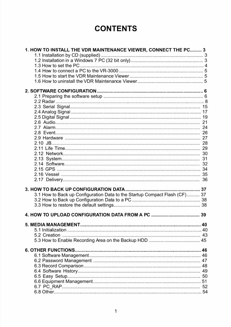
8102019 Ome44376d Vr3000 Mainte Cof26amp3bmol
httpslidepdfcomreaderfullome44376d-vr3000-mainte-cof26amp3bmol 357
1
CONTENTS
1 HOW TO INSTALL THE VDR MAINTENANCE VIEWER CONNECT THE PC 3
11 Installation by CD (supplied) 3
12 Installation in a Windows 7 PC (32 bit only) 3
13 How to set the PC 4
14 How to connect a PC to the VR-3000 5
15 How to start the VDR Maintenance Viewer 5
16 How to uninstall the VDR Maintenance Viewer 5
2 SOFTWARE CONFIGURATION 6
21 Preparing the software setup 6
22 Radar 8
23 Serial Signal 15
24 Analog Signal 17
25 Digital Signal 19
26 Audio 21
27 Alarm 24
28 Event 26
29 Hardware 27
210 JB 28
211 Life Time 29
212 Network 30
213 System 31
214 Software 32
215 GPS 34
216 Vessel 35
217 Delivery 36
3 HOW TO BACK UP CONFIGURATION DATA 37
31 How to Back up Configuration Data to the Startup Compact Flash (CF) 37
32 How to Back up Configuration Data to a PC 38
33 How to restore the default settings 38
4 HOW TO UPLOAD CONFIGURATION DATA FROM A PC 39
5 MEDIA MANAGEMENT 40
51 Initialization 40
52 Creation 43
53 How to Enable Recording Area on the Backup HDD 45
6 OTHER FUNCTIONS 46
61 Software Management 46
62 Password Management 47
63 Record Comparison 48
64 Software History 49
65 Easy Setup 50
66 Equipment Management 51
67 PC_RAP 52
68 Other 54
8102019 Ome44376d Vr3000 Mainte Cof26amp3bmol
httpslidepdfcomreaderfullome44376d-vr3000-mainte-cof26amp3bmol 457
2
This manual describes how to set the VR-3000VR-3000S after installation The outline of
the setup is as below
Step 1 Network setting on PC and VDR
Step 2 Software setting
Step 3 Backup data setting
Step 4 Software configuration from file data
Step 5 Media management
Step 6 Other functions
After setting up make a backup copy of configuration data onto the CompactFlash (CF)
and the PC
Parts and Equipment needed
a) PC with Internet Explorer 60
b) Ethernet cross cable
8102019 Ome44376d Vr3000 Mainte Cof26amp3bmol
httpslidepdfcomreaderfullome44376d-vr3000-mainte-cof26amp3bmol 557
3
1 How to Install the VDR MaintenanceViewer Connect the PC
11 Installation by CD (supplied)
Live Player V4 and the VDR Maintenance Viewer Program are included in the accessory
CD Install these programs in the PC
1 Place the CD in the PC CD drive
2 The contents of the CD are displayed in a window Double click on the file ldquoviewexerdquoThe Installation Wizard opens
3 Follow the directions of the Installation Wizard
The Live Player V4 and Maintenance Viewer are installed in the computer The Live
Player V4 is not required for use here
12 Installation in a Windows 7 PC (32 bit only)
This section provides the procedure for the installation of the VDR Maintenance Viewer ina Windows 7 PC
Deactivate the firewall
Temporarily deactivate the Windows 7 firewall to install and operate the VDR
Maintenance Viewer
1 Open the Control Panel
2 Select Network and Internet
3 Select Network and Sharing Center
4 Select Windows Firewall from the left window
5 Select Turn Windows Firewall on or off from the left window
6 At Public network location settings select Turn off Windows Firewall (notrecommended) then click the OK button
If you try to use the VDR Maintenance Viewer with the firewall active the following
occurs
bull VDR settings cannot be downloaded when the Live Player V4 is connected
bull Data cannot be replayed when the Backup HDD is connected to LAN Data extraction
and analysis also are not possible
bull VDR settings cannot be downloaded or updated from the VDR Maintenance Viewer
To reactivate the firewall select Turn on Windows firewall at step 6 in the procedure
8102019 Ome44376d Vr3000 Mainte Cof26amp3bmol
httpslidepdfcomreaderfullome44376d-vr3000-mainte-cof26amp3bmol 657
4
How to grant administrator rights
Run the VDR Maintenance Viewer program as an Administrator to install it
1 Click the Start button select All Programs and check that VR-3000 appears
2 Select LivePlayerV4 at VR-3000 right click then select Properties
3 Select Compatibility from the Live Player V4 Properties dialog box
4 At Privilege Level check Run this program as an administrator
5 Select MaintenanceViewer at VR-3000 right click then select Properties
6 Select Compatibility from the menu in the MaintenanceViewer Properties dialogbox
7 At Privilege Level check Run this program as an administrator then click the OK button
How to install the VDR Maintenance Viewer software
1 Double click VR-3000_verexe ( is version number)2 The Setup ndash VR-3000 dialog box appears click the Next button
3 Confirm that the install location is CProgram Files then click the Next button
4 The Folder Exists dialog box appears click the Yes button
5 After the Folder Exists dialog box disappears click the Next and Install buttons
6 After the installation is completed the message Yes restart computer now ischecked then click the Finish button
13 How to set the PC
Before connecting to VR-3000VR-3000S set the IP address and subnet mask of the PC
as below The IP address of VR-3000VR-3000S is 1000100
Windows XP
1 Click Start Settings Control Panel and Network Connections
2 Click Local Window Network Properties and Internet Protocol (TCPIP)
3 Click the Properties button
4 Choose ldquoUse the following addressrdquo
5 Enter IP address and subnet mask
IP address 1000102 or 100099 (other than 1000100)
Subnet mask 255000
6 Click the OK button and then click it again
Windows Vista
1 Click Start Control Panel Network and Internet Network and Sharing Center
2 Click View status to show the Local Window Connection Status dialog box and clickthe Properties button
3 Select Internet Protocol Version 4 (TCPIP v4) and click the Properties button
4 Select Use the following IP address and enter IP address and subnet maskIP address 1000102 or 100099 (other than 1000100)Subnet mask 255000
5 Click the OK button and then click it again on the next screen
6 Restart the PC
8102019 Ome44376d Vr3000 Mainte Cof26amp3bmol
httpslidepdfcomreaderfullome44376d-vr3000-mainte-cof26amp3bmol 757
5
Windows 7
1 Click Start Control Panel Network and Internet Network and Sharing Center
2 Click the Properties button on the Local Area Connection Status dialog box
3 Select Internet Protocol Version 4 (TCPIP v4) then click the Properties button
4 Click the Use the following IP address button
5 Enter IP address and subnet mask
IP address 1000102 or 100099 (other than 1000100)Subnet mask 255000
6 Click the OK button and then click the Close button
7 Restart the PC
14 How to connect a PC to the VR-3000
Use an Ethernet cross cable to connect a PC to J14 (DATA) in the DCU
Ethernetcross cable
DCU
PC
J14 (DATA)
15 How to start the VDR Maintenance Viewer
Windows XP START menu gt VR-3000 gt VDR Maintenance Viewer
Windows Vista START menu gt All Programs gt VR-3000 gt VDR Maintenance Viewer
Windows 7 START menu gt All Programs gt VR-3000 gt VDR Maintenance Viewer
16 How to uninstall the VDR Maintenance ViewerUninstall the software as an Administrator
For Windows XP
1 Click START menu gt VR-3000 gt VR-3000 Uninstall
Uninstall the software following the wizard shown on the display
2 Delete the VDRViewer folder saved in the My Computer gt Local Disk (C) gt Program Files
folder
For Windows Vista or Windows 7
1 Click START menu gt All Programs gt VR-3000 gt VR-3000 UninstallUninstall the software following the wizard shown on the display
2 Delete the VDRViewer folder saved in the My Computer gt Local Disk (C) gt Program Files
folder
8102019 Ome44376d Vr3000 Mainte Cof26amp3bmol
httpslidepdfcomreaderfullome44376d-vr3000-mainte-cof26amp3bmol 857
6
2 Software ConfigurationDisconnect the Remote Alarm Panel until the software configuration is completed
otherwise an alarm (grabber failure or no radar video) sounds
Procedure
1 In the Maintenance Viewer log in to Serviceman2 Download the configuration data from the VDR into the Maintenance Viewer
3 Set each tab (Refer from section 22 for further explanation)
4 After each tab has been set up save the data to the VDR
5 Lastly click the write button to backup the set data to the DRU Backup HDD and the CF
21 Preparing the software setup
To configure VR-3000VR-3000S software with the VDR Maintenance Viewer do the
following
1 Make sure that the PC and DRU are connected securely to the DCU2 Turn on the VDR and wait about three minutes
3 Download ldquoequipxmlrdquo from the VDR to the PC using the following steps
1 Open Internet Explorer on the PC
2 Enter the URL ftp1000100pub to access the VDR from the PC
3 Copy the file ldquoequipxmlrdquo and paste it onto the PC desktop
4 Start the VDR Maintenance Viewer
5 Enter the IP address1000100 in the Maintenance Login dialog box
6 Checkmark ldquoServicemanrdquo enter the password and click the OK button
Note Do not release the password to unauthorized personnel
If the connection is successful the information shown below appears in the status
window- System Time - RAP LEDs - POWER STATUS- DRU Information - Backup HDD Information
If an error message appears the IP address or password may be wrong or the cable
between the PC and VDR is not correctly connected
7 Check the memory size of the DRU and Backup HDD that appear in the status
window
If the memory size display shows MB (data read error) restart the VDR If the
display still does not change check that the DRU and HDD are correctly connected
8102019 Ome44376d Vr3000 Mainte Cof26amp3bmol
httpslidepdfcomreaderfullome44376d-vr3000-mainte-cof26amp3bmol 957
7
Example of acceptable memory size displays
Backup HDD InformationSelected AREA2Size 37864 MB
6GB DRU InformationSelected DRUSize 5794 MB or more
9GB DRU InformationSelected DRUSize 8822 MB or more
8 Select PC_RAP from the Tool menu
Confirm Alarm box in PC_RAP When a 3xx error is displayed as above the data is not
input correctly Data settings are explained on the page 12 If error messages 094 098
018 022 etc are displayed remove the error before going to the next step Refer to the
VDR Operatorrsquos Manual or error code list for definitions of the meanings of individual
error codes
9 Click the X button at the top right corner to close the PC_RAP
10 From the menu select Maintenancegt Equipment Managementgt Import
11 Select the file ldquoequipxmlrdquo from the desktop and click [open]
12 From the menu select Maintenancegt VDR Config Managementgt Download Click
the OK button and then [Close]
If the configuration file has already been downloaded the 12th step is not necessary
The following explanation refers to setting individual tabs
On the signal tab there is an Information Area (left) and a Setting Area (right) Select the
channel to set in the Information Area on the left by selecting it with the cursor and then
set it in the Setting Area on the right The results of the updated setting are displayed in
the Information Area After setting each channel click SET to finish
8102019 Ome44376d Vr3000 Mainte Cof26amp3bmol
httpslidepdfcomreaderfullome44376d-vr3000-mainte-cof26amp3bmol 1057
8
22 RadarRadar Setup is performed in the Radar Tab
Equipment Setup
1 Click the Radar tab
The Radar information setup screen appears
2 Select a radar channel from the Information area For example click the CH No1 boxto open the corresponding setup
3 Click the Select Equipment button in the Setting Area The following dialogue boxappears
4 Select a radar model
For example as in the above illustration select Radargt RadarInterfacegtFurunogtFAR-28x7gt SXGA(60Hz) and click the OK button As in thefollowing illustration FAR-28x7 appears in the Type No field in the CH No 1 of theInformation Area Detailed information about the selected radar appears in the Setting Area
8102019 Ome44376d Vr3000 Mainte Cof26amp3bmol
httpslidepdfcomreaderfullome44376d-vr3000-mainte-cof26amp3bmol 1157
9
If your radar model is not in the list enter the required information manually Thesetting values are the same as the previous Web Configuration values
5 Click the Image Capture button in the Setting Area Confirm the correct video signal6 If required update the Setting Area item contents
It is not necessary to enter information very every item in the Setting Area For easyidentification of Input Source enter Equipment Category Brand Type No and DataName
7 Click the Set button to finish
8 To setup multiple radars repeat steps 2 through 7
9 Click the Check button in the setting area to perform radar check Results appear inthe Check section of the Information Area
8102019 Ome44376d Vr3000 Mainte Cof26amp3bmol
httpslidepdfcomreaderfullome44376d-vr3000-mainte-cof26amp3bmol 1257
10
To import the exact settings to another ship save the settings of the device in the Setting Area to the PC database
1 Click on Reflect Equipment
2 Copy the file to the PC by using Maintenancegt Equipment Managementgt Export inthe menu
3 Import to the other shiprsquos VDR from the PC
How to Set the Record Pattern
When there are two or more Radar units connected to the VDR select which radar torecord to
Note When using a 6 GB DRU it possible to record to 1 channel and when using a 9 GBDRU it is possible to record to 2 channels
1 In the Setting Area click the Recording Mode button The following dialogue boxappears
R1-R4 1st Radar (CH No1)~4
th Radar (CH No4)
G Records signal to the youngest radar number in a group pattern (ex R1-R4 aregrouped) If the youngest number is inactive signal is recorded to the next youngestnumber in sequence within the group
I Indicated unit recordssends
N Indicated unit does not recordsend
2 Select a recording pattern from Patterns 1-4
For example the settings in the above illustration are as follows
Recording Pattern 1 R1 signal is recorded to DRU R2 ndash R4 do not record
R1 and R2 signals are recorded to the Backup HDD R3ndashR4 donot record
Network Sending R1-R4 all send to network
Recording Pattern 3 Recording signal to the DRU automatically routes to the nextyoungest active number in the group between R1 and R3 R4 Does not recordExample If R1 is inactive signal is recorded to R2
Recording to Backup HDD Same as DRU
Send to Network R1-R4 all is sent to the network
3 Update I and N as needed
8102019 Ome44376d Vr3000 Mainte Cof26amp3bmol
httpslidepdfcomreaderfullome44376d-vr3000-mainte-cof26amp3bmol 1357
11
Place the cursor above either I or N and left click to alternate With this I is set torecord while N is set to not record G cannot be changed
4 After completing setup click the OK button
5 To record settings to the database click Reflect Equipment in the Setting Area
How to Enter Information Manually
This VDR system receives in VESA (Video Electronics Standards Association) signal Image signal 05-1Vpp (When using composite signal the minimum synchronization
signal is 50 mV)
Horizontal Synchronization Signal Max plusmn91146 kHz
Vertical Synchronization Signal Max 35 Hz
Acceptable Image Resolution 640x480 ndash 1280x1024
Channel number conforms to the number displayed by the DCU
To set the Radar tab do the following
1 Click the Radar tab
2 Choose the channel with the entered Radar Image from the Information Area
3 Check the Active box in the Setting Area and enter the Horizontal and Verticalresolution of the incoming image in the Horizontal resolution and Vertical resolutioncolumns
4 Click the Set button
5 Click the Image Capturehellip button The Image Capture dialogue box appears
6 Click the Test button in the Image Capture window Radar image appears a fewseconds later
7 If the image is normal close the Image Capture window8 Input each item in the Setting Area
8102019 Ome44376d Vr3000 Mainte Cof26amp3bmol
httpslidepdfcomreaderfullome44376d-vr3000-mainte-cof26amp3bmol 1457
12
Items are as follows
Active Check a channel to activate it
Brand Enter brand nameType No Enter type noCheck Set and activate checkData Name Enter data nameHorizontal resolution Set horizontal resolutionVertical resolution Set vertical resolutionHorizontal Offset Move the picture horizontallyVertical offset Move the picture verticallyPLL This sets the frequency of the PLL-oscillatorCDEV Set CDEV
VCOSL Set VCO Signal LeadPhase (0-63) Phase setting selects the phase of the sampling clock relativeto phase locked loop signal in 64 steps of 5625 degrees IfPhase is not set correctly any section of an image consistingof vertical lines may show line ldquotearingrdquo
Sync Type Select the type of video sync signalHorizontal sync polarity Set the polarity of the horizontal sync signalVertical sync polarity Set the polarity of the vertical sync signalHDVD Sync Termination Sets horizontal and vertical synchronization point When
using a composite signal set to 75ohmsPulse Width for VD Detection (0-1020 Step4) Sets the pulse width for video signal
detectionInterlace Type When the video image is interlace set ldquoInterlaceldquo sampling
mode In Interlace mode the even pixels are sampled on oneframe and odd pixels are sampled on the other frame
8102019 Ome44376d Vr3000 Mainte Cof26amp3bmol
httpslidepdfcomreaderfullome44376d-vr3000-mainte-cof26amp3bmol 1557
13
Interlace Polarity Set interlace polarityITRP (0-4092 Step4) Enter interlace pulse positionITRW (0-4092 step4) Enter interlace pulse widthSampling Rate Display sampling rate Fixed at ldquo15 secondsrdquoCompress Type (viewer) Set compress type (viewer)Color Bit Display and set Color BitChange Pump Current Set pump current Fixed at ldquo05 mArdquo
Video Clock Polarity Set video clock polarity Fixed at ldquoThroughrdquoCounter Clock SelectionSelect counter clock selection Fixed at ldquo49 MHzrdquoVCO Clock Hold Sets VCO clock holdRed Gain (0-255) Enter red gainGreen Gain (0-255) Enter green gainBlue Gain (0-255) Enter blue gainRed Offset (0-255) Enter red offsetGreen Offset (0-255) Enter green offsetBlue Offset (0-255) Enter blue offsetBlack Level (0-255) Enter black levelEquipment Category Enter equipment category
Board Name Enter board name for corresponding channelNote Enter note
Note Offset Phase and Color Bit change with the length of the antenna cable
Marked Items For easy identification of input source enter Equipment Category Brand
Type No and Data Name
Measurement BoxThe Measurement Box is located on the left side of the Information Area The LOWHorizontal and Vertical counter should be higher than the HIGH counter If reversely the
HIGH counter is higher than the LOW counter it is possible that the SYNC Polaritysettings are adjusted incorrectly
8102019 Ome44376d Vr3000 Mainte Cof26amp3bmol
httpslidepdfcomreaderfullome44376d-vr3000-mainte-cof26amp3bmol 1657
14
Config Management
After all items have been set up proceed to the final setting management This can only
be executed one time after all tabs have been set up
1 Click on VDR Config Management in the Maintenance menu
2 Click on the Upload button to send all sent data to the VDR memory
3 Click each individual Write button to record to DRU Backup HDD and CF Note
If the settings are not uploaded to the VDR they have no effect on the unit
4 Click the Close button to close the VDR Config Management Dialogue Box
8102019 Ome44376d Vr3000 Mainte Cof26amp3bmol
httpslidepdfcomreaderfullome44376d-vr3000-mainte-cof26amp3bmol 1757
15
23 Serial Signal
The Serial tab sets the RS-422 signals received at the terminal board (SI01-SI08) and the
junction box (SI09-SI72) This channel is not only for NMEA but also binary and ASCII
data
Set the Serial tab as follows1 Click the Serial tab
2 Select a channel from the Information window
3 Click the Select Equipment button in the Setting Area
4 Choose the unit that is connected to the indicated Channel and click the OK Button
5 Adjust items as needed in the Setting Area
8102019 Ome44376d Vr3000 Mainte Cof26amp3bmol
httpslidepdfcomreaderfullome44376d-vr3000-mainte-cof26amp3bmol 1857
16
6 After finishing the settings for one channel click the Set buttonNote Be sure to do this before moving another channel
7 Repeat steps 2-6 to set up each channel
When running Config Management for Tab Settings
1 From the Maintenance menu click VDR Config Management and then Config
2 Click the Upload button to record data to the VDR memory3 Click the Write button to save data to the DRU backup HDD and CF
The buttons in the Setting Area are as followsSet Save edited dataCapture Received data shown in the serial window dialog boxSelect Equipment Select equipment settings (saved to the database) to reflect in
a channelReflect Equipment Save the equipment setting data to the databaseCheck Check all channels OK or NG (No Good) shown in
Information window
Individual Item ExplanationActive Put check in check box to make channel activeBrand Enter brand nameType No (Equipment Name) Set type no (equipment name)Check Do equipment checkData Name Enter data nameData Type Enter data typeBaud Rate Set baud rate (Available for SI01 to SI08)Data Bit Set number of bits (Available for SI01 to SI08)Parity Bit Set parity bit (Available for SI01 to SI08)Stop Bit Set stop bit (Available for SI01 to SI08)Source Checksum Enter checksum for GPS sourceTime out Set time outEquipment Category Set equipment categoryBoard Name Enter board names where channels are presentNote Enter note
Marked Items For easy identification of input source enter Equipment Category Brand
Type No Date and Name
8102019 Ome44376d Vr3000 Mainte Cof26amp3bmol
httpslidepdfcomreaderfullome44376d-vr3000-mainte-cof26amp3bmol 1957
17
24 Analog SignalAnalog signal is input via Junction Box IF-8530 (optional for VR-3000S)Receivable signal ndash10 to +10 V or 4 to 20mA
Connect the analog signal to V and G terminals on the Junction Box When 4 to 20 mAsignal is connected make a short circuit between the V and I input terminals with jumper
wireThe basic procedure for setting up the analog signal is as follows
1 Click the Analog tab
2 Select channel from the Information Area
3 Set detailed information of the selected channel in the Setting Area Refer to thefollowing illustration to enter detailed item information
In the factory settings there is no preset data when the Select Equipment button is
pressed In the case that the setup was completed on another ship and saved usingReflect Equipment import the data by clicking Select Equipment and choosing thesaved data
4 In the following order calibrate the Analog signal
① Click the Calibration button in the Setting Area
② Enter the voltage (or current) value for Calibration Point 1 and thecorresponding engineering value in the left and right boxes
③ Enter values for Calibration Point 2④ Enter unit for the values in Engineering Value Unit
8102019 Ome44376d Vr3000 Mainte Cof26amp3bmol
httpslidepdfcomreaderfullome44376d-vr3000-mainte-cof26amp3bmol 2057
18
In the above image the Engineering Value Unit is set to degrees (deg) TheCalibration Point 1 is -10V corresponding to 0 degrees Calibration Point 2 is10V corresponding to 30 degrees This is set corresponding to the connectedanalog sensor
When the Apply button is clicked the New Engineering Value of 29835Vcorresponding to the input Voltage of 989V is displayed in the bottom fieldWhenever the input value is changed this value also changes Check that theNew Engineering Value is within an appropriate range
Another method is to observe the Voltage (or Current) field in the top field andpress the Hold button of Point 1 when an appropriate value is displaying Dothis again for Point 2
⑤ Click the OK Button
5 When setting is complete click the Set button Be sure to do this before movinganother to channel
6 Repeat steps 1-5 to set up all channels
When using Config Manager with Tabs
1 From the Maintenance menu click VDR Config Management and then Config
2 Click the Upload button to record to VDR memory
3 Click the Write buttons to record to DRU Backup HDD and CF memory
The items in the Setting Area are as shown below Active Put check in check box to make channel activeBrand Enter brand name
Type No Set type no (equipment name)
Check Do equipment checkData Name Enter data nameData Type Analog Data type (0~10V -10~10v 4~20mV)
Sampling Rate Display sampling rateCalibration Active Disable and enable analog calibrationCalibration Point 1 Enter calibration point 1
Calibration Point 1 Value Enter calibration point 1 valueCalibration Point 2 Enter calibration point 2Calibration Point 2 Value Enter calibration point 2 valueEngineering Value Unit Enter engineering value unit
8102019 Ome44376d Vr3000 Mainte Cof26amp3bmol
httpslidepdfcomreaderfullome44376d-vr3000-mainte-cof26amp3bmol 2157
19
Note For -marked boxes values that are set at the Analog Calibration dialog box aredisplayed
Equipment Category Set equipment categoryBoard Name Enter board names where channels are presentNote Enter note
Marked Items For easy identification of input source enter Equipment CategoryBrand Type No Data and Name
25 Digital Signal
Digital signal is connected via Junction Box IF-8530 (optional for VR-3000S) The
receivable signal is 10-32 V for voltage signal or contact signal For voltage signal
connect to A and B input terminals on the Junction Box For contact signal connect to B
and G input terminals on the Junction Box Also make a short-circuit between the 24 and
A input terminals with a jumper wire
To set up the Digital tab
1 Click the Digital tab
2 Select a channel from the Information Area
3 Set up the digital signal from the Setting Area Refer to the following individual item
explanation
In the factory settings there is no preset data when the Select Equipment button is
pressed In the case that the setup was completed on another ship and saved using
Reflect Equipment import the data by clicking Select Equipment and choosing the
saved data
4 When setting Digital Signal to each 64 channel group perform the following
directions1 Click the Calibration button in the setting area
8102019 Ome44376d Vr3000 Mainte Cof26amp3bmol
httpslidepdfcomreaderfullome44376d-vr3000-mainte-cof26amp3bmol 2257
20
2 Check the active column of the channel group being set
3 Enter the status in columns 0 and 1 of that group
4 Click the OK Button
5 When finished setting up click the Set button
6 Repeat steps 2-5 to set up other channels
When using Config Manager with Tabs
1 From the Maintenance menu click VDR Config Management
2 Click the Upload button to record to VDR memory
3 Click the Write buttons to record to DRU Backup HDD and CF memory
The items in the Setting Area are as shown below
Active Put check in check box to make channel activeBrand Enter brand name
Type No Set type no (equipment name)Check Do equipment checkData Name Enter and display data nameContact Type Set contact type NO normal open NC normal closeSampling Rate Display sampling rateCalibration Active Disable and enable digital calibrationActive Status (1) Set status display when (1) is activeActive Status (0) Set status display when (0) is activeEquipment Category Set equipment categoryBoard Name Enter board names where channels are presentNote Enter note
Marked Items For easy identification of input source enter Equipment CategoryBrand Type No Date and Name
8102019 Ome44376d Vr3000 Mainte Cof26amp3bmol
httpslidepdfcomreaderfullome44376d-vr3000-mainte-cof26amp3bmol 2357
21
26 Audio
Microphone and VHF audio settings are performed in the Audio tab
Set the items in the Audio tab as shown below
1 Click the Audio tab
2 Select channel from the Information Area3 Click Select Equipment in the Setting Area
4 Click on the connected device in the indicated channel The setting contents aredisplayed in the Information and Setting Areas
5 If required update the item contents in the Setting Area Refer to the detailed itemexplanation below
6 After completing settings for a channel click the Set buttonNote Be sure to click the Set button before moving to another channel
7 Repeat steps 2-6 to set up other channels
8102019 Ome44376d Vr3000 Mainte Cof26amp3bmol
httpslidepdfcomreaderfullome44376d-vr3000-mainte-cof26amp3bmol 2457
22
When using Config Manager with tabs
1 From the Maintenance menu click VDR Config Management
2 Click the Upload button to record to VDR memory
3 Click the Write buttons to record to DRU Backup HDD and CF memory
MIC testDo the MIC test to check whether audio is received clearly in adequate level or not
1 Click the MIC TEST button in the Setting Area
2 Click the TEST button in the MIC Test dialogue box MIC test results are displayed in
the MIC Test dialogue box
3 Click the Close button to close the dialogue box
Note Not the same recordingplayback function as the previous Web Configuratorsoftware
Continuous MIC TestRun the continuous MIC test as needed accordingly
1 Click the Continuous MIC Test button in the Setting Area2 Set up how many times to perform in the Continuous MIC Test dialogue box and click
the Test button
3 Click the Close button to close the dialogue box
8102019 Ome44376d Vr3000 Mainte Cof26amp3bmol
httpslidepdfcomreaderfullome44376d-vr3000-mainte-cof26amp3bmol 2557
23
Active Put check in check box to make channel activeBrand Enter and display brand nameType No Set type no (equipment name)Check Do equipment checkData Name Enter data nameInput Type Enter input type Sampling Data Bit Displays sampling data bit rate
Sampling Frequency Displays Sampling FrequencyCodec Sets MIC typeMIC Test Active M1M3M5 Put a checkmark when performing MIC Test of M1M3M5MIS Test Active M2M4M6 Put a checkmark when performing MIC Test of M2M4M6 MIC M1M3M5 Position Enter MIC position of MIC M1M3M5MIC M2M4M6 Position Enter MIC position of MIC M2M4M6Threshold Level M1M3M5 Enter MIC test threshold level of MIC M1M3M5Threshold Level M2M4M6 Enter MIC test threshold level of MIC M2M4M6Equipment Category Set equipment categoryBoard Name Enter board names where channels are present
Note Enter note Marked Items For easy identification of input source enter Equipment Category BrandType No Date and Name
8102019 Ome44376d Vr3000 Mainte Cof26amp3bmol
httpslidepdfcomreaderfullome44376d-vr3000-mainte-cof26amp3bmol 2657
24
27 Alarm
Alarm and Alarm Status settings are found in the Alarm tab
The Alarm tab shows the following information about alarms Click the Time Categoryand Name tabs in the title bar to sort
Time Time of alarm
Category Alarm categoryName Name of alarm
Number Alarm number
Status Alarm status
Alarm Search
1 Click the Search button above the Alarm tab The Search dialogue box appears
2 Add a checkmark to any desired search items (multiple items can be selected)
Start Time Display name of alarms generated after a certain time
End Time Display name of alarms generated before a certain time
Name Display information for alarm name entered
8102019 Ome44376d Vr3000 Mainte Cof26amp3bmol
httpslidepdfcomreaderfullome44376d-vr3000-mainte-cof26amp3bmol 2757
25
Number Display information for alarm number entered
Status Display alarm status for alarm name entered
3 In the checked items column input the desired search items
4 Click the Search Button
Close the Search box to cancel a search
Note During a search the upper left Mode changes from Play to Search andDisplay search related information
8102019 Ome44376d Vr3000 Mainte Cof26amp3bmol
httpslidepdfcomreaderfullome44376d-vr3000-mainte-cof26amp3bmol 2857
26
28 Event
Click the items shown below to sort by item selected
Note You can sort the items in ascending order () descending order () and
initialization order (no symbol)
Time Time an event occurred
Category Category of an event
Name Name of an event
Contents1 Display data associated with log
Contents2 Display data associated with log
Event Search
Do the following to search events
1 Click the Search button on the upper right of the Event tab
2 In the dialogue box add a checkmark to desired search items Multiple items can bechecked
Start Time Display name of event generated after a certain time
End Time Display name of event generated before a certain time
Name Display event names entered
Number Display event numbers entered
Status Display event status entered
Enter information about the checked event to search in the character input box
3 Click the Search button
Note The mode changes from Play to Search when performing a search
8102019 Ome44376d Vr3000 Mainte Cof26amp3bmol
httpslidepdfcomreaderfullome44376d-vr3000-mainte-cof26amp3bmol 2957
27
29 Hardware
The Hardware tab provides information about the system hardware
The buttons in the Setting window work as follows
Self Check Status Display status of self check
CPU Display information about the CPU
Memory Size Display memory size
CPU Board Display status of CPU board
Audio Board Display status of Audio board
Serial Board Display status of Serial board
Radar Interface Board Display status of Radar Interface boardNote Enter and display note
Marked items are optional
8102019 Ome44376d Vr3000 Mainte Cof26amp3bmol
httpslidepdfcomreaderfullome44376d-vr3000-mainte-cof26amp3bmol 3057
28
210 JB
Connect the Junction Box to the DCU before turning on the system
The JB tab functions to set up the Junction Box
The basic procedure for setting up the Junction Box is as follows
1 Click the JB tab2 Select a Junction Box from the Information Area
3 Set up the Junction Box from the Setting Area
4 Click the Set button (Be sure to do this before moving to another channel)5 Click the Check button to perform an inspection on all channels In the Information
Area check column either OK or NG (No Good) is displayed
When using Config Manager with Tabs
1 From the Maintenance menu click VDR Config Management
2 Click the Upload button to record to VDR memory
3 Click the Write buttons to record to DRU Backup HDD and CF
The items in the Setting window work as followsActive Put check in check box to make channel activeNo Display Junction Box numberIP Address Display IP address of Junction Box acquired by VDRMAC Address Display MAC address of Junction Box acquired by VDRCheck Enable and disable equipment checkNote Enter note
Marked items are optional
8102019 Ome44376d Vr3000 Mainte Cof26amp3bmol
httpslidepdfcomreaderfullome44376d-vr3000-mainte-cof26amp3bmol 3157
29
211 Life Time
The Life Time tab controls consumable parts
The basic procedure for using the Life Time tab is as follows
1 Click the Life Time tab
2 Select a Type No in the Information Area3 Set up the chosen part from Setting Area
4 Click the Set button
Note Be sure to click the Set button before moving to set up a different Type
The items in the Setting window work as follows
Type No Enter and display type no
Data Name Enter and display data name
Level Set replacement level Legal Exchange Parts or Normal Exchange Parts
Replace Date Enter and display recommended day of replacement
Lifetime Term Not usedNote Enter and display note
The Status column of the Information Area displays as follows
OK The recommended date of replacement shown in the Replace Date
box in the Information window has not passed
Out of Date The date of replacement has passed
None The date of replacement has not been set
8102019 Ome44376d Vr3000 Mainte Cof26amp3bmol
httpslidepdfcomreaderfullome44376d-vr3000-mainte-cof26amp3bmol 3257
30
212 Network
The Network tab sets the system network
The basic procedure for setting up the system network is as follows
1 Click the Network tab
2 Select a port from the Information Area
3 Set up the network from the Setting Area
4 Click the Set button
Note1 Be sure to click the Set button before moving to set up a different Port
Note2 After setting the system network reboot the VDR to apply the settings
The items in the Setting window work as follows
LAN Type Enter LAN type Public LAN or JB LAN
MAC Address Enter MAC address
IP Address Enter IP address
Subnet Mask Enter subnet mask
Gateway Address Enter gateway address
Live Play Multicast Mode (Only JB LAN) Check box to enable live player multicast
mode
Multicast Address (Only Public LAN) Enter and display live player multicast addressNote Enter note
Marked items are optional
8102019 Ome44376d Vr3000 Mainte Cof26amp3bmol
httpslidepdfcomreaderfullome44376d-vr3000-mainte-cof26amp3bmol 3357
31
213 System
The System tab sets system related functions
The basic procedure for using the System tab is as follows
1 Click the System tab
2 Set up the chosen item from the Setting Area
3 Click the Set button
Note Be sure to click the Set button before moving to a different tab
The items in the Setting window work as follows
VDR Type Enter type of VDR
VDR Model Enter model number of VDR
Radar Interface Check Enable and disable checking of the Radar Interface board
Junction Box Count Enter number of junction boxes in system
DRU Flash Count Enter number of DRU flash disks in system Set 1 when DRU
serial no is 5000 and more Set 3 when DRU serial no is less
than 5000
DRU Capacity Display capacity of DRU
Backup HDD Capacity Display capacity of Backup HDD
VDR Config Version Display version no of VDR
VDR Config Date Display the number of hours the VDR settings have
been saved
VDR Config Code Display configuration identity code
Installation Engineer Enter name of the equipment installer
Installation Company Enter name of installers company
8102019 Ome44376d Vr3000 Mainte Cof26amp3bmol
httpslidepdfcomreaderfullome44376d-vr3000-mainte-cof26amp3bmol 3457
32
Installation Date Enter the date of the installation
MIC Test Time Enter the date of the MIC test
Note Enter note Marked items are optional
USB memory logging Do not check Enable
IEEE1394 BUS Error Auto Restart function Not used
IEEE1394 Active Node Count Do not change the default value of 3 (However set to 5
for serial number 5000 or less of DRU)
IEEE1394 Recover Process Limit Count Do not change the default value of 10
DRU Error Auto Restart function Not used
REBOOT DELAY TIME (sec) Do not change the default value of 10
LIMIT REBOOT COUNT Do not change the default value of 10
Live Player Max Connection Count The max number of Live Player V4 that can be
connected simultaneously The default no is two
but a maximum of five can be set here After you
change this option reboot the VDR to apply the
setting Disconnect the cable connected with
Live Player V4 (PC) from the VDR and thenreconnect it
214 Software
The Software tab sets and display software-related operations
The basic procedure for using the Software tab is as follows
1 Click the Software tab
2 Set up the chosen Item from the Setting Area
3 Click the Set button
8102019 Ome44376d Vr3000 Mainte Cof26amp3bmol
httpslidepdfcomreaderfullome44376d-vr3000-mainte-cof26amp3bmol 3557
33
The items in the Setting window work as follows
VDR System Program Display the VDR system program no
Process Version Display the process version
Power Distribution Unit (PDU) Display the version no of the PDU
Operation System Display the version no of the OS
Audio Driver Display the version no of the audio driverRAP Version Enter the version no of the RAP
AP Version Enter the version no of the AP
JB1-8 Boot Program Display the no of the RJB Boot program for Junction Boxes
1 to 8
JB1-8 App Program Display the no of the RJB App program for Junction Boxes
1 to 8
Watch Dog Interval Do not change the default value of 60 (Enter the process
response time A process is repeated if there is no response
within the time interval set here)
Giveup Interval Do not change the default value of 300 (Enter the restart
watch time The restarting of a process is stopped when the
number of times it has been restarted is exceeded within the
interval set here)
Refork Limit Do not change the default value of 10 (Enter the upper limit
for process restart The restarting of a process is stopped
when the number of times it has been restarted exceeds the
Give up Interval)
Note Enter note
Marked Items are optional
8102019 Ome44376d Vr3000 Mainte Cof26amp3bmol
httpslidepdfcomreaderfullome44376d-vr3000-mainte-cof26amp3bmol 3657
34
215 GPS
The GPS tab sets GPS-related parameters
The basic procedure for using the GPS tab is as follows
1 Click the GPS tab
2 Set up the chosen channel from the Information window3 Set up the chosen item in the Setting Area
4 Click the Set button
5 Repeat steps 2-4 to set up each Channel
6 Click the Check button to perform an inspection on all channels In the Information Area check column either OK or NG (No Good) is displayed
The items in the Setting window work as follows
Priority Display priority order
Date and Time SourceShip Position Source Set GPS source channel (serial channel
number for ZDA sentence)
Check Enable and disable checking
GPS Antenna Position From Bow Enter position of GPS antenna from bow
GPS Antenna Position From Stern Enter position of GPS antenna from stern
GPS Antenna Position From Port Enter position of GPS antenna from port
GPS Antenna Position From Starboard Enter position of GPS antenna from starboard
GPS Failure Threshold If the ZDA is input within the set time limit
the system restarts synchronized If not
input within the time limit the system restarts
without synchronization
8102019 Ome44376d Vr3000 Mainte Cof26amp3bmol
httpslidepdfcomreaderfullome44376d-vr3000-mainte-cof26amp3bmol 3757
35
GPS Delay Time by Time Sync Enter minimum time delay for time
synchronization Time synchronization is started
only in the time set here
GPS Difference Interval The time set here is added to the GPS time to
synchronize the system time Leave at the default
0 value setting
GPS Sync Giveup Time If the system receives the GPS time within the
time set the system synchronizes with the time
When not receiving a signal the system displays
an ldquoerror 26rdquo message
ZDA Timeout Enter value (seconds) for ZDA timeout (234 error)
from GPS
Note Enter and display note
Marked Items are optional
216 VesselThe Vessel tab sets and displays own ships information such as name and IMO number
The basic procedure for using the Vessel tab is as follows
1 Click the Vessel tab
2 Set up information in the Setting window
3 Click the Set button (Be sure to do this before moving to another port)
4 From the Maintenance menu click VDR Config Management and then Config5 Click the Write buttons to save data to the DRU backup HDD CF
The buttons in the Setting window works as follows
Vessel Name Enter name of vessel
Vessel IMO Number Enter IMO number of vessel
Vessel Flag Enter flag of vessel
Approval of Authority Enter name of approving authority
Note Enter note
Marked items are optional
8102019 Ome44376d Vr3000 Mainte Cof26amp3bmol
httpslidepdfcomreaderfullome44376d-vr3000-mainte-cof26amp3bmol 3857
36
217 Delivery
The Delivery tab functions to transmit data from the VDR to a PC via Ethernet LAN Do
not use this function during live connection
The basic procedure for using the Delivery tab is as follows
1 Click the Delivery tab
2 Click the Add button to show the Delivery Config window
3 Select protocol from the Protocol drop-down box (Unicast or Multicast)
4 Enter IP address in the IP address input box
5 Enter port number in the port number input box
6 Click the tab of the data to send (Analog Digital or Serial)
7 Select the channel of the data to send
8 If Serial was selected at step 6 select applicable data sentence from the Inactivewindow Click the right arrow to move the data sentence to the Active window
9 Click the OK button to close the Delivery Config window
10 The settings are listed in a table in the Delivery window Check the checkbox in the
Active column and then click the Set button
The buttons in the Setting window works as follows
Set Save edited settings
Add Create new delivery settings
Modify Modify selected delivery settings
Delete Delete selected delivery settings
8102019 Ome44376d Vr3000 Mainte Cof26amp3bmol
httpslidepdfcomreaderfullome44376d-vr3000-mainte-cof26amp3bmol 3957
37
3 How to Back up Configuration DataThis chapter shows how to back up configuration data to various storage media
Configuration data can be opened with Word Pad or any text editor other than Notepad
31 How to Back up Configuration Data to the Startup CompactFlash (CF)
Back up data to the startup CF after setting the VDR Configuration data is created on the
CF as a configini file
Note When the error shown below occurs during the downloading or uploading of
configuration data check the connection of the DRU Backup HDD and CF and then
upload or download the configuration data again
[CONN] Download failed
[CONN] Could not upload config file
If error occurs again re-install the VDR Maintenance Viewer
Do the following to back up data to a CF
1 Set up parameters on the tabs referring to Chapter 2
2 Click the Maintenance menu
3 Select VDR Config Management
4 Click the Upload button
5 A confirmation box appears click the OK button to start uploading to the VDR
6 Click the Write button where the arrow connects between VDR and DRU BackupHDD
7 A confirmation window appears click the OK button to save the configuration data tothe DRU and Backup HDD
8102019 Ome44376d Vr3000 Mainte Cof26amp3bmol
httpslidepdfcomreaderfullome44376d-vr3000-mainte-cof26amp3bmol 4057
38
8 Click the Write button where the arrow connects between the VDR and CF
9 A confirmation window appears click the OK button to save the configuration data tothe startup CF
10 Check that the PC VDR DRU Backup HDD and CF share the same VDR configcode
32 How to Back up Configuration Data to a PC
Configuration data saved to the PC can be edited with Wordpad and shared with other
vessels For future service ease it is recommended to backup configuration data to the
PC and have the data on board the vessel Also it is recommended to upload this data to
Furuno SMS (Service Management System) If unable to upload to Furuno SMS please
contact the Service Center Furuno Japan
To back up configuration data to the PC do as follows
1 Set up parameters on the tabs referring to Chapter 2
2 Click the Maintenance menu
3 Select VDR Config Management
4 Click the Export to button
5 A confirmation window appears click the OK button
6 Select where to save the data enter file name then click the Open button
7 Confirm that back up file is in the location selected
33 How to restore the default settings
Click the Default button on the VDR Config Management window to restore the default
settings of the DRU Backup HDD CF and VDR Maintenance Viewer
8102019 Ome44376d Vr3000 Mainte Cof26amp3bmol
httpslidepdfcomreaderfullome44376d-vr3000-mainte-cof26amp3bmol 4157
39
4 How to Upload Configuration Datafrom a PCThe procedure below shows how to upload configuration from the PC to aVR-3000VR-3000S
1 Click the Maintenance menu
2 Select VDR Config Management
3 Click the Import from button
4 The Open window appears Select configuration data and then click the Open button
5 Click the Upload button to upload data to the VR-3000VR-3000S
6 Click the Write buttons to save data to the DRU backup HDD and CF
8102019 Ome44376d Vr3000 Mainte Cof26amp3bmol
httpslidepdfcomreaderfullome44376d-vr3000-mainte-cof26amp3bmol 4257
40
5 Media ManagementThe media management feature deletes data from recording media initialization the
system etc There are two method LAN connection and Direct connection The Direct
connection takes longer time than the LAN connection Basically use the LAN connection
method
Note Initialization or creation of recording media is not available when Source Select onthe Live Player V4 is selected to Backup HDD
51 Initialization
This section shows how to delete data from the recording media Configuration data is
not deleted After performing the software configuration delete the data from the DRU
and HDD
Do the following to delete data from the DRU (LAN connection)
1 Set the PlaybackCPU switch in the DCU to the CPU position
2 Use an Ethernet cross cable to connect the PC to J14 (DATA) in the DCU (See page5)
3 Open the Tool menu
4 Select Media Management to open the VDR Media Management window
5 Check that IP address shown in the ldquoLAN Connect to IPrdquo in VDR Media Table Area isthe same as the IP address access point
6 Select ldquoLAN Connect to IPrdquo in the VDR Media Table column
8102019 Ome44376d Vr3000 Mainte Cof26amp3bmol
httpslidepdfcomreaderfullome44376d-vr3000-mainte-cof26amp3bmol 4357
41
7 Click the Analyze button A list of recording media connected to the VDR appears
Put a checkmark in the checkbox of the Select column for the DRU in the Name columnNote If there are several flash memories in the DRU all flash memories are shownCheck all flash memories shown
8 Select ldquoDRU Initializerdquo from the Operation dropdown list in the Operation area
10 Click the Run button
Do the following to delete data from the DRU (Direct connection)
1 Start Live Player V4 software
2 Open the Tool menu and select Source Select Select Live from the pull-downmenu
3 Click the Alarm tab and open Alarm History
4 Set the PlaybackCPU switch in the DCU to the Playback position
5 Wait approx 10 minutes and confirm that Alarm 174 occurs on Alarm History of LivePlayer V4
6 Connect an IEEEE1394 cable between J6 in the DCU and the PC
7 Open the Tool menu
8 Select Media Management to show the VDR Media Management window
9 Select Direct in the VDR Media Table column
10 Click the Analyze button A list of recording media connected to the VDR appears
11 Put a checkmark in the checkbox of the Select column for the DRU in the Namecolumn
Note If there are several flash memories in the DRU all flash memories are shownCheck all flash memories shown
12 Select ldquoDRU Initializerdquo from the Operation dropdown list in the Operation area
13 Enter password in the password column
14 Click the RUN button
8102019 Ome44376d Vr3000 Mainte Cof26amp3bmol
httpslidepdfcomreaderfullome44376d-vr3000-mainte-cof26amp3bmol 4457
42
Delete data from the Backup HDD as follows (LAN connection)
1 Set the PlaybackCPU switch in the DCU to the CPU position
2 Check that an Ethernet cross cable is connected between J14 in the DCU and the PC
3 Open the Tool menu
4 Select Media Management to open the VDR Media Management window
5 Check that IP address shown in the LAN Connect to IP in VDR Media Table Area is
the same as the IP address access point6 Select LAN Connect to IP in the VDR Media Table column
7 Click the Analyze button
8 A list of recording media connected to the VDR appears
9 Put a checkmark in the box of the Select column for the Backup HDD in the Namecolumn Select ldquoBackup HDD Initializerdquo from the Operation dropdown list in theOperation area
10 Click the Run button
Delete data from the Backup HDD as follows (Direct connection)
1 Start Live Player V4 software
2 Open the Tool menu and select Source Select Select Live from the pull-downmenu
3 Click the Alarm tab and open Alarm History
4 Set the PlaybackCPU switch in the DCU to the Playback position
5 Wait approx 10 minutes and confirm that Alarm 174 occurs on Alarm History of LivePlayer V4
6 Connect an IEEE1394 cable between J6 in the DCU and the PC
7 Open the Tool menu
8 Select Media Management to open the VDR Media Management window9 Select Direct in the VDR Media Table window
10 Click the Analyze button A list of recording media connected to the VDR appears
11 Put a checkmark in the check box of the Select column for the Backup HDD in theName column Select ldquoBackup HDD Initializerdquo from the Operation dropdown list in theOperation area
12 Enter password
13 Click the Run button
8102019 Ome44376d Vr3000 Mainte Cof26amp3bmol
httpslidepdfcomreaderfullome44376d-vr3000-mainte-cof26amp3bmol 4557
43
52 CreationThe Creation feature initializes recording media
Note1 This feature deletes ALL configuration data Backup all VDR configuration data
Note2 When you initialize medium that is a different format for the DRU or Backup HDDdelete all partitions with the disk management tool of Windows
Note3 When the Creation is failed try again If you can not initialize recording media tryunder condition as shown below
Do the Creation by the direct connection (When the Creation by the LAN
connection is failed)
Delete all partitions of the DRU or Backup HDD with the disk management tool of
Windows to do the Creation
If the Creation is still failed request service to repairreplace the DRU or Backup
HDD
Initialize the DRU as follows (LAN connection)
1 Set the PlaybackCPU switch in the DCU to the CPU position
2 Check that an Ethernet cross cable is connected between J14 in the DCU and the PC
3 Open the Tool menu
4 Select Media Management to open the VDR Media Management window
5 Check that IP address shown in the LAN Connect to IP in VDR Media Table Area isthe same as the IP address access point
6 Check ldquoLAN Connect to IPrdquo in the VDR Media Table column
7 Click the Analyze button A list of recording media connected to the VDR appears
8 Put a checkmark in the box of the Select column for the DRU in the Name column
Select ldquoDRU Creationrdquo from the Operation dropdown list in the Operation area
9 Click the Run button
Initialize the Backup HDD as follows (LAN connection)
1 To format the Backup HDD place a checkmark in the Select column of the listedrecord media in the Name column of the VDR Media Management dialogue box
2 From the Operation drop down list of the Operation area select ldquoBackup HDDCreation (Radar) or ldquoBackup HDD Creationrdquo
Two partition tools are available for the Backup HDD in the Media Management as
below
Backup HDD creation
This tool is used when the number of the SXGA video signal connected to the BackupHDD is the same as the DRU The same partition is created on both DRU and HDD
(1) When two SXGA video signals are recorded onto the HDD while 9-GB DRU isconnected
(2) When an SXGA video signal is recorded onto the HDD while 6-GB DRU isconnected
Backup HDD creation (radar)
This tool is used when two SXGA video signals are recorded onto the HDD with 6-GB
DRU connected The HDD has an area (radar) to record the second radar signal inaddition to the same partition as the DRU This tool cannot be used when 9-GB DRUis connected
3 Press the Run Button
8102019 Ome44376d Vr3000 Mainte Cof26amp3bmol
httpslidepdfcomreaderfullome44376d-vr3000-mainte-cof26amp3bmol 4657
44
Initialize the DRU as follows (Direct connection)
1 Start Live Player V4 software
2 Open the Tool menu and select Source Select Select Live from the pull-downmenu
3 Click the Alarm tab and open Alarm History
4 Set the PlaybackCPU switch in the DCU to the Playback position
5 Wait approx 10 minutes and confirm that Alarm 174 occurs on Alarm History of LivePlayer V4
6 Connect an IEEE1394 cable between J6 in the DCU and the PC
7 Open the Tool menu
8 Select Media Management to open the VDR Media Management window
9 Select Direct in the VDR Media Table window
10 Click the Analyze button A list of recording media connected to the VDR appears
11 Put a checkmark in the box of the Select column for the DRU and the desiredrecording media in the Name column In the Operation dropdown list of the Operationarea select ldquoDRU Creationrdquo
12 Enter password in the password column
13 Click the Run button
Initialize the Backup HDD as follows (Direct Connection)
1 To format the Backup HDD place a checkmark in the Select column of the listedrecord media in the Name column of the VDR Media Management dialogue box
2 From the Operation column of the Operation area select ldquoBackup HDD Creation(Radar) or ldquoBackup HDD Creationrdquo
Backup HDD creation
This tool is used when the number of the SXGA video signal connected to the BackupHDD is the same as the DRU The same partition is created on both DRU and HDD
(1) When two SXGA video signals are recorded onto the HDD while 9-GB DRU is
connected
(2) When an SXGA video signal is recorded onto the HDD while 6-GB DRU is
connected
Backup HDD creation (radar)
This tool is used when two SXGA video signals are recorded onto the HDD with 6-GBDRU connected The HDD has an area (radar) to record the second radar signal inaddition to the same partition as the DRU This tool cannot be used when 9-GB DRUis connected
3 Enter the password in the Password column
4 Press the Run Button
8102019 Ome44376d Vr3000 Mainte Cof26amp3bmol
httpslidepdfcomreaderfullome44376d-vr3000-mainte-cof26amp3bmol 4757
45
53 How to Enable Recording Area on the Backup HDD
This function enables writing over a recording area To prevent falsification of data all
recording areas must be saved otherwise this function is disabled To use this function push
the SAVE button Save the data before doing this procedure
Note Software version 135 or higher can enable writing over a recording area even if
all recording areas are not saved
Recording enable (LAN connection)
1 Set the PlaybackCPU switch in the DCU to the CPU position
2 Check that an Ethernet cross cable is connected between J14 in the DCU and the PC
3 Open the Tool menu
4 Select Media Management to open the VDR Media Management window
5 Check that IP address shown in the ldquoLAN Connect to IPrdquo in VDR Media Table Area isthe same as the IP address access point
6 Select ldquoLAN Connect to IPrdquo in the VDR Media Table column7 Click the Analyze button A list of recording media connected to the VDR appears
8 Put a checkmark in the box of the Select column for the Backup HDD in the Namecolumn
9 Select ldquoBackup HDD Recording Area Enablerdquo from the Operation dropdown list in theOperation area
10 Click the Run button
Recording enable (Direct connection)
1 Start Live Player V4 software
2 Open the Tool menu and select Source Select Select Live from the pull-down menu3 Click the Alarm tab and open Alarm History
4 Set the PlaybackCPU switch in the DCU to the Playback position
5 Wait approx 10 minutes and confirm that Alarm 174 occurs on Alarm History of LivePlayer V4
6 Connect an IEEE1394 cable between J6 in the DCU and the PC
7 Open the Tool menu
8 Select Media Management to open the VDR Media Management window
9 Select Direct in the VDR Media Table window
10 Click the Analyze button A list of recording media connected to the VDR appears11 Put a checkmark in the box of the Select column for the Backup HDD in the Name
column
12 Select ldquoBackup HDD Recording Area Enablerdquo from the Operation dropdown list in theOperation area
13 Enter password
14 Click the Run button
8102019 Ome44376d Vr3000 Mainte Cof26amp3bmol
httpslidepdfcomreaderfullome44376d-vr3000-mainte-cof26amp3bmol 4857
46
6 Other Functions
61 Software Management
The software download feature downloads VDR system software to the PC
To download software
1 Click the Maintenance menu
2 From the Software Management menu click Software Download to show theSoftware Download window
3 Enter the IP address 1000100 in the IP address box in the Update Server area
4 Click the Download Software button
5 The confirmation window appears click the OK button
The Software Backup Execute window shows the results of the download
Software is downloaded to C Program Files VDR Viewer Viewer Backup The software file
name is vdrtar
To Update Software
VDR system program version 16x can update the software with the procedure shownbelow
Note Do not update the file downloaded in procedures above
1 Click the Maintenance menu
2 From the Software Management menu click Software Upload to show the SoftwareUpload area
3 Click the Select button to show the Open window
4 Select update file (vdrtar) and click the Open button
8102019 Ome44376d Vr3000 Mainte Cof26amp3bmol
httpslidepdfcomreaderfullome44376d-vr3000-mainte-cof26amp3bmol 4957
47
5 Check the displayed Software information is correct
6 Enter the IP address 1000100 in the IP address box in the Update Server area
7 Enter password
8 Click the Update button
After the updating is completed the VDR is automatically restarted
Note Click the Restore button on the Software Update window to restore previoussoftware version This feature is available after updating the software
62 Password Management
The password can be changed for a serviceman to access the equipment Contact
FURUNO to get the default password to use during installation
Serviceman password
1 Click the Maintenance menu2 Select Change Serviceman Password from Password Management to show the
Change Serviceman Password window
3 Enter current password in the Old Password box
4 Enter the new password in the New Password box of the Change Password area
5 Enter new password again in the Confirm New Password box
6 Click the OK button
Audio password
The audio password set at the VDR Maintenance Viewer can be removed to enable
audio access without password1 Click the Maintenance menu
2 Select Change Audio Password from Password Management to show the Change Audio Password window
3 The confirmation window appears click the OK button
8102019 Ome44376d Vr3000 Mainte Cof26amp3bmol
httpslidepdfcomreaderfullome44376d-vr3000-mainte-cof26amp3bmol 5057
48
63 Record ComparisonThe integrity of the DRU and Backup HDD recordings can be compared This function isused by the RampD engineer for debugging
Follow the procedure as shown below
1 Click the Maintenance menu2 Select Record Comparison to show the Record Comparison window
The results are shown every 15 seconds in the Record Comparison window
8102019 Ome44376d Vr3000 Mainte Cof26amp3bmol
httpslidepdfcomreaderfullome44376d-vr3000-mainte-cof26amp3bmol 5157
49
64 Software History
This section shows you to save and configure software history (communications record)
How to save software history
Note When the error dialog appears while saving the software history restart the VDR
Maintenance Viewer
1 Click the Maintenance menu
2 Select Software History Collect
3 Click the Select button The Open dialog box appears
4 Select where to save the data then click the Open button
5 Select desired save condition then click the OK buttonNone No savingAt Once Save the software history manually Saving begins as soon as the OK button is clickedPeriodic For debugging Do not use otherwise The intervals are 30 sec 60 secand 120 secAlarm Detection For debugging Do not use otherwise Software history is savedwhen specified alarm is released Enter alarm number
How to configure software communications record
The RampD engineer uses this function for debugging Do not do this procedure unless
required Malfunction can result
1 Click the Maintenance menu
2 Select Software History Config
3 Do the followingProcess Select the type of communications record to save ALL saves allcommunications records
Detail Hide or show detailed information4 Click the Send button
8102019 Ome44376d Vr3000 Mainte Cof26amp3bmol
httpslidepdfcomreaderfullome44376d-vr3000-mainte-cof26amp3bmol 5257
50
65 Easy SetupThis feature sets equipment settings in batch and creates a data file of those settings
Default template The default template is created with the settings entered at installation
1 Click the Maintenance menu
2 Select Easy Setup to show the Template Selection window
3 Select Default Template
4 Click the Start button to show the Easy Setup window
5 Right click the channels (Radar Audio Digital Serial Analog) then select Edit toshow the Equipment Selection window
6 From the Equipment Directory window select equipment connected to the selectedchannel and then click the OK button
7 Repeat steps 5 and 6 to select equipment settings for each channel
8 Click the Save button in the Easy Setup window to show the Save window
9 Select where to save the file and enter file name
10 Click the Save button
8102019 Ome44376d Vr3000 Mainte Cof26amp3bmol
httpslidepdfcomreaderfullome44376d-vr3000-mainte-cof26amp3bmol 5357
51
Specific template Use a file already created
1 Click the Maintenance menu
2 Select Easy Setup to show the Template Selection window
3 Check Specified Template
4 Click the Select button and then select the file to edit
5 Click the Start button to show the Easy Setup window
6 Right click the channels (Radar Audio Digital Serial Analog) then select Edit toshow the Equipment Selection window
7 From the Equipment Directory window select equipment connected to the selectedchannel and then click the OK button
8 Repeat steps 6 and 7 to select equipment settings for each channel
9 Click the Save button in the Easy Setup window to show the Save window
10Select where to save the file and enter file name
11 Click the Save button
66 Equipment Management
This feature controls the import and export of equipment settings
Import data file
Import data files of equipment settings created in Easy Setup etc to the VDR
1 Click the Maintenance menu
2 Select Import from Equipment Management to show the Open window
3 Select the data file to import and click Open
Export data file
Export data files of equipment settings from the VDR to a PC
1 Click the Maintenance menu
2 Select Export from Equipment Management to show the Save window
3 Enter file name
4 Click the Save button
8102019 Ome44376d Vr3000 Mainte Cof26amp3bmol
httpslidepdfcomreaderfullome44376d-vr3000-mainte-cof26amp3bmol 5457
52
67 PC_RAP
This feature enables the same operation of the RAP (Remote Alarm Panel) from a PC
Select PC_RAP from the Tool menu to show the PC_RAP window
The buttons in the PC_RAP window function as shown below
SAVE Stop recording in the area where recording is currently being done
ACK Silence audio alarm
The PC_RAP display shows the following information with LEDs
RAP_LEDs Display the status of LEDs on the RAPSave The Save button blinks yellow when pushed When the 4 memory
areas have data recorded to them the Save button lights orange when
pushed
Normal Lights (green) where there are no unconfirmed or not restored
alarms
Error Flashes (red) for not confirmed alarm Lights (red) for unrestored
alarm
8102019 Ome44376d Vr3000 Mainte Cof26amp3bmol
httpslidepdfcomreaderfullome44376d-vr3000-mainte-cof26amp3bmol 5557
53
Backup HDD Information Display status of backup HDD
Selected Display current recording area and its status in green for
normal operation and in red for abnormal operation
Size Display capacity of backup HDD
Alarm area displays unconfirmed alarms
Time Display time alarm was generatedNumber Display number of alarm
Name Display name of alarm
Pending Alarm displays the unrestored alarms out of confirmed alarms only
Time Display time alarm was generated
Number Display number of alarm
Name Display name of alarm
8102019 Ome44376d Vr3000 Mainte Cof26amp3bmol
httpslidepdfcomreaderfullome44376d-vr3000-mainte-cof26amp3bmol 5657
54
68 Other
Status Monitor
The status monitor feature provides comprehensive data about the status of the VDR
From the menu bar click Toolgt Status Monitor to show the Status Monitor window
The buttons in the Status Monitor window work as shown below
Reload Settings for automatic refreshing of the status monitor
ON Turn automatic refresh OFF
OFF The Status Monitor is refreshed every five seconds
Save Available when Reload ON is selected The contents of the Status Monitor can be
saved to a text fileUpdate Update the Status Monitor display
Close Close the Status Monitor display
8102019 Ome44376d Vr3000 Mainte Cof26amp3bmol
httpslidepdfcomreaderfullome44376d-vr3000-mainte-cof26amp3bmol 5757
VDR Error List
This feature compiles all the errors shown on the RAP for easy reference
Access from MenugtToolgtVDR Error List
The VDR error list contains the following information
NO Display the number of the error
Title Display the name of the error
Detail Display details about the error
Exchange Check
This feature removes the alarms generated when replacing the DRU or backup HDD
Access MenugtToolgtExchange Check select either DRU or Backup HDD and click OK
Reboot
Reboot the VDR
8102019 Ome44376d Vr3000 Mainte Cof26amp3bmol
httpslidepdfcomreaderfullome44376d-vr3000-mainte-cof26amp3bmol 657
4
How to grant administrator rights
Run the VDR Maintenance Viewer program as an Administrator to install it
1 Click the Start button select All Programs and check that VR-3000 appears
2 Select LivePlayerV4 at VR-3000 right click then select Properties
3 Select Compatibility from the Live Player V4 Properties dialog box
4 At Privilege Level check Run this program as an administrator
5 Select MaintenanceViewer at VR-3000 right click then select Properties
6 Select Compatibility from the menu in the MaintenanceViewer Properties dialogbox
7 At Privilege Level check Run this program as an administrator then click the OK button
How to install the VDR Maintenance Viewer software
1 Double click VR-3000_verexe ( is version number)2 The Setup ndash VR-3000 dialog box appears click the Next button
3 Confirm that the install location is CProgram Files then click the Next button
4 The Folder Exists dialog box appears click the Yes button
5 After the Folder Exists dialog box disappears click the Next and Install buttons
6 After the installation is completed the message Yes restart computer now ischecked then click the Finish button
13 How to set the PC
Before connecting to VR-3000VR-3000S set the IP address and subnet mask of the PC
as below The IP address of VR-3000VR-3000S is 1000100
Windows XP
1 Click Start Settings Control Panel and Network Connections
2 Click Local Window Network Properties and Internet Protocol (TCPIP)
3 Click the Properties button
4 Choose ldquoUse the following addressrdquo
5 Enter IP address and subnet mask
IP address 1000102 or 100099 (other than 1000100)
Subnet mask 255000
6 Click the OK button and then click it again
Windows Vista
1 Click Start Control Panel Network and Internet Network and Sharing Center
2 Click View status to show the Local Window Connection Status dialog box and clickthe Properties button
3 Select Internet Protocol Version 4 (TCPIP v4) and click the Properties button
4 Select Use the following IP address and enter IP address and subnet maskIP address 1000102 or 100099 (other than 1000100)Subnet mask 255000
5 Click the OK button and then click it again on the next screen
6 Restart the PC
8102019 Ome44376d Vr3000 Mainte Cof26amp3bmol
httpslidepdfcomreaderfullome44376d-vr3000-mainte-cof26amp3bmol 757
5
Windows 7
1 Click Start Control Panel Network and Internet Network and Sharing Center
2 Click the Properties button on the Local Area Connection Status dialog box
3 Select Internet Protocol Version 4 (TCPIP v4) then click the Properties button
4 Click the Use the following IP address button
5 Enter IP address and subnet mask
IP address 1000102 or 100099 (other than 1000100)Subnet mask 255000
6 Click the OK button and then click the Close button
7 Restart the PC
14 How to connect a PC to the VR-3000
Use an Ethernet cross cable to connect a PC to J14 (DATA) in the DCU
Ethernetcross cable
DCU
PC
J14 (DATA)
15 How to start the VDR Maintenance Viewer
Windows XP START menu gt VR-3000 gt VDR Maintenance Viewer
Windows Vista START menu gt All Programs gt VR-3000 gt VDR Maintenance Viewer
Windows 7 START menu gt All Programs gt VR-3000 gt VDR Maintenance Viewer
16 How to uninstall the VDR Maintenance ViewerUninstall the software as an Administrator
For Windows XP
1 Click START menu gt VR-3000 gt VR-3000 Uninstall
Uninstall the software following the wizard shown on the display
2 Delete the VDRViewer folder saved in the My Computer gt Local Disk (C) gt Program Files
folder
For Windows Vista or Windows 7
1 Click START menu gt All Programs gt VR-3000 gt VR-3000 UninstallUninstall the software following the wizard shown on the display
2 Delete the VDRViewer folder saved in the My Computer gt Local Disk (C) gt Program Files
folder
8102019 Ome44376d Vr3000 Mainte Cof26amp3bmol
httpslidepdfcomreaderfullome44376d-vr3000-mainte-cof26amp3bmol 857
6
2 Software ConfigurationDisconnect the Remote Alarm Panel until the software configuration is completed
otherwise an alarm (grabber failure or no radar video) sounds
Procedure
1 In the Maintenance Viewer log in to Serviceman2 Download the configuration data from the VDR into the Maintenance Viewer
3 Set each tab (Refer from section 22 for further explanation)
4 After each tab has been set up save the data to the VDR
5 Lastly click the write button to backup the set data to the DRU Backup HDD and the CF
21 Preparing the software setup
To configure VR-3000VR-3000S software with the VDR Maintenance Viewer do the
following
1 Make sure that the PC and DRU are connected securely to the DCU2 Turn on the VDR and wait about three minutes
3 Download ldquoequipxmlrdquo from the VDR to the PC using the following steps
1 Open Internet Explorer on the PC
2 Enter the URL ftp1000100pub to access the VDR from the PC
3 Copy the file ldquoequipxmlrdquo and paste it onto the PC desktop
4 Start the VDR Maintenance Viewer
5 Enter the IP address1000100 in the Maintenance Login dialog box
6 Checkmark ldquoServicemanrdquo enter the password and click the OK button
Note Do not release the password to unauthorized personnel
If the connection is successful the information shown below appears in the status
window- System Time - RAP LEDs - POWER STATUS- DRU Information - Backup HDD Information
If an error message appears the IP address or password may be wrong or the cable
between the PC and VDR is not correctly connected
7 Check the memory size of the DRU and Backup HDD that appear in the status
window
If the memory size display shows MB (data read error) restart the VDR If the
display still does not change check that the DRU and HDD are correctly connected
8102019 Ome44376d Vr3000 Mainte Cof26amp3bmol
httpslidepdfcomreaderfullome44376d-vr3000-mainte-cof26amp3bmol 957
7
Example of acceptable memory size displays
Backup HDD InformationSelected AREA2Size 37864 MB
6GB DRU InformationSelected DRUSize 5794 MB or more
9GB DRU InformationSelected DRUSize 8822 MB or more
8 Select PC_RAP from the Tool menu
Confirm Alarm box in PC_RAP When a 3xx error is displayed as above the data is not
input correctly Data settings are explained on the page 12 If error messages 094 098
018 022 etc are displayed remove the error before going to the next step Refer to the
VDR Operatorrsquos Manual or error code list for definitions of the meanings of individual
error codes
9 Click the X button at the top right corner to close the PC_RAP
10 From the menu select Maintenancegt Equipment Managementgt Import
11 Select the file ldquoequipxmlrdquo from the desktop and click [open]
12 From the menu select Maintenancegt VDR Config Managementgt Download Click
the OK button and then [Close]
If the configuration file has already been downloaded the 12th step is not necessary
The following explanation refers to setting individual tabs
On the signal tab there is an Information Area (left) and a Setting Area (right) Select the
channel to set in the Information Area on the left by selecting it with the cursor and then
set it in the Setting Area on the right The results of the updated setting are displayed in
the Information Area After setting each channel click SET to finish
8102019 Ome44376d Vr3000 Mainte Cof26amp3bmol
httpslidepdfcomreaderfullome44376d-vr3000-mainte-cof26amp3bmol 1057
8
22 RadarRadar Setup is performed in the Radar Tab
Equipment Setup
1 Click the Radar tab
The Radar information setup screen appears
2 Select a radar channel from the Information area For example click the CH No1 boxto open the corresponding setup
3 Click the Select Equipment button in the Setting Area The following dialogue boxappears
4 Select a radar model
For example as in the above illustration select Radargt RadarInterfacegtFurunogtFAR-28x7gt SXGA(60Hz) and click the OK button As in thefollowing illustration FAR-28x7 appears in the Type No field in the CH No 1 of theInformation Area Detailed information about the selected radar appears in the Setting Area
8102019 Ome44376d Vr3000 Mainte Cof26amp3bmol
httpslidepdfcomreaderfullome44376d-vr3000-mainte-cof26amp3bmol 1157
9
If your radar model is not in the list enter the required information manually Thesetting values are the same as the previous Web Configuration values
5 Click the Image Capture button in the Setting Area Confirm the correct video signal6 If required update the Setting Area item contents
It is not necessary to enter information very every item in the Setting Area For easyidentification of Input Source enter Equipment Category Brand Type No and DataName
7 Click the Set button to finish
8 To setup multiple radars repeat steps 2 through 7
9 Click the Check button in the setting area to perform radar check Results appear inthe Check section of the Information Area
8102019 Ome44376d Vr3000 Mainte Cof26amp3bmol
httpslidepdfcomreaderfullome44376d-vr3000-mainte-cof26amp3bmol 1257
10
To import the exact settings to another ship save the settings of the device in the Setting Area to the PC database
1 Click on Reflect Equipment
2 Copy the file to the PC by using Maintenancegt Equipment Managementgt Export inthe menu
3 Import to the other shiprsquos VDR from the PC
How to Set the Record Pattern
When there are two or more Radar units connected to the VDR select which radar torecord to
Note When using a 6 GB DRU it possible to record to 1 channel and when using a 9 GBDRU it is possible to record to 2 channels
1 In the Setting Area click the Recording Mode button The following dialogue boxappears
R1-R4 1st Radar (CH No1)~4
th Radar (CH No4)
G Records signal to the youngest radar number in a group pattern (ex R1-R4 aregrouped) If the youngest number is inactive signal is recorded to the next youngestnumber in sequence within the group
I Indicated unit recordssends
N Indicated unit does not recordsend
2 Select a recording pattern from Patterns 1-4
For example the settings in the above illustration are as follows
Recording Pattern 1 R1 signal is recorded to DRU R2 ndash R4 do not record
R1 and R2 signals are recorded to the Backup HDD R3ndashR4 donot record
Network Sending R1-R4 all send to network
Recording Pattern 3 Recording signal to the DRU automatically routes to the nextyoungest active number in the group between R1 and R3 R4 Does not recordExample If R1 is inactive signal is recorded to R2
Recording to Backup HDD Same as DRU
Send to Network R1-R4 all is sent to the network
3 Update I and N as needed
8102019 Ome44376d Vr3000 Mainte Cof26amp3bmol
httpslidepdfcomreaderfullome44376d-vr3000-mainte-cof26amp3bmol 1357
11
Place the cursor above either I or N and left click to alternate With this I is set torecord while N is set to not record G cannot be changed
4 After completing setup click the OK button
5 To record settings to the database click Reflect Equipment in the Setting Area
How to Enter Information Manually
This VDR system receives in VESA (Video Electronics Standards Association) signal Image signal 05-1Vpp (When using composite signal the minimum synchronization
signal is 50 mV)
Horizontal Synchronization Signal Max plusmn91146 kHz
Vertical Synchronization Signal Max 35 Hz
Acceptable Image Resolution 640x480 ndash 1280x1024
Channel number conforms to the number displayed by the DCU
To set the Radar tab do the following
1 Click the Radar tab
2 Choose the channel with the entered Radar Image from the Information Area
3 Check the Active box in the Setting Area and enter the Horizontal and Verticalresolution of the incoming image in the Horizontal resolution and Vertical resolutioncolumns
4 Click the Set button
5 Click the Image Capturehellip button The Image Capture dialogue box appears
6 Click the Test button in the Image Capture window Radar image appears a fewseconds later
7 If the image is normal close the Image Capture window8 Input each item in the Setting Area
8102019 Ome44376d Vr3000 Mainte Cof26amp3bmol
httpslidepdfcomreaderfullome44376d-vr3000-mainte-cof26amp3bmol 1457
12
Items are as follows
Active Check a channel to activate it
Brand Enter brand nameType No Enter type noCheck Set and activate checkData Name Enter data nameHorizontal resolution Set horizontal resolutionVertical resolution Set vertical resolutionHorizontal Offset Move the picture horizontallyVertical offset Move the picture verticallyPLL This sets the frequency of the PLL-oscillatorCDEV Set CDEV
VCOSL Set VCO Signal LeadPhase (0-63) Phase setting selects the phase of the sampling clock relativeto phase locked loop signal in 64 steps of 5625 degrees IfPhase is not set correctly any section of an image consistingof vertical lines may show line ldquotearingrdquo
Sync Type Select the type of video sync signalHorizontal sync polarity Set the polarity of the horizontal sync signalVertical sync polarity Set the polarity of the vertical sync signalHDVD Sync Termination Sets horizontal and vertical synchronization point When
using a composite signal set to 75ohmsPulse Width for VD Detection (0-1020 Step4) Sets the pulse width for video signal
detectionInterlace Type When the video image is interlace set ldquoInterlaceldquo sampling
mode In Interlace mode the even pixels are sampled on oneframe and odd pixels are sampled on the other frame
8102019 Ome44376d Vr3000 Mainte Cof26amp3bmol
httpslidepdfcomreaderfullome44376d-vr3000-mainte-cof26amp3bmol 1557
13
Interlace Polarity Set interlace polarityITRP (0-4092 Step4) Enter interlace pulse positionITRW (0-4092 step4) Enter interlace pulse widthSampling Rate Display sampling rate Fixed at ldquo15 secondsrdquoCompress Type (viewer) Set compress type (viewer)Color Bit Display and set Color BitChange Pump Current Set pump current Fixed at ldquo05 mArdquo
Video Clock Polarity Set video clock polarity Fixed at ldquoThroughrdquoCounter Clock SelectionSelect counter clock selection Fixed at ldquo49 MHzrdquoVCO Clock Hold Sets VCO clock holdRed Gain (0-255) Enter red gainGreen Gain (0-255) Enter green gainBlue Gain (0-255) Enter blue gainRed Offset (0-255) Enter red offsetGreen Offset (0-255) Enter green offsetBlue Offset (0-255) Enter blue offsetBlack Level (0-255) Enter black levelEquipment Category Enter equipment category
Board Name Enter board name for corresponding channelNote Enter note
Note Offset Phase and Color Bit change with the length of the antenna cable
Marked Items For easy identification of input source enter Equipment Category Brand
Type No and Data Name
Measurement BoxThe Measurement Box is located on the left side of the Information Area The LOWHorizontal and Vertical counter should be higher than the HIGH counter If reversely the
HIGH counter is higher than the LOW counter it is possible that the SYNC Polaritysettings are adjusted incorrectly
8102019 Ome44376d Vr3000 Mainte Cof26amp3bmol
httpslidepdfcomreaderfullome44376d-vr3000-mainte-cof26amp3bmol 1657
14
Config Management
After all items have been set up proceed to the final setting management This can only
be executed one time after all tabs have been set up
1 Click on VDR Config Management in the Maintenance menu
2 Click on the Upload button to send all sent data to the VDR memory
3 Click each individual Write button to record to DRU Backup HDD and CF Note
If the settings are not uploaded to the VDR they have no effect on the unit
4 Click the Close button to close the VDR Config Management Dialogue Box
8102019 Ome44376d Vr3000 Mainte Cof26amp3bmol
httpslidepdfcomreaderfullome44376d-vr3000-mainte-cof26amp3bmol 1757
15
23 Serial Signal
The Serial tab sets the RS-422 signals received at the terminal board (SI01-SI08) and the
junction box (SI09-SI72) This channel is not only for NMEA but also binary and ASCII
data
Set the Serial tab as follows1 Click the Serial tab
2 Select a channel from the Information window
3 Click the Select Equipment button in the Setting Area
4 Choose the unit that is connected to the indicated Channel and click the OK Button
5 Adjust items as needed in the Setting Area
8102019 Ome44376d Vr3000 Mainte Cof26amp3bmol
httpslidepdfcomreaderfullome44376d-vr3000-mainte-cof26amp3bmol 1857
16
6 After finishing the settings for one channel click the Set buttonNote Be sure to do this before moving another channel
7 Repeat steps 2-6 to set up each channel
When running Config Management for Tab Settings
1 From the Maintenance menu click VDR Config Management and then Config
2 Click the Upload button to record data to the VDR memory3 Click the Write button to save data to the DRU backup HDD and CF
The buttons in the Setting Area are as followsSet Save edited dataCapture Received data shown in the serial window dialog boxSelect Equipment Select equipment settings (saved to the database) to reflect in
a channelReflect Equipment Save the equipment setting data to the databaseCheck Check all channels OK or NG (No Good) shown in
Information window
Individual Item ExplanationActive Put check in check box to make channel activeBrand Enter brand nameType No (Equipment Name) Set type no (equipment name)Check Do equipment checkData Name Enter data nameData Type Enter data typeBaud Rate Set baud rate (Available for SI01 to SI08)Data Bit Set number of bits (Available for SI01 to SI08)Parity Bit Set parity bit (Available for SI01 to SI08)Stop Bit Set stop bit (Available for SI01 to SI08)Source Checksum Enter checksum for GPS sourceTime out Set time outEquipment Category Set equipment categoryBoard Name Enter board names where channels are presentNote Enter note
Marked Items For easy identification of input source enter Equipment Category Brand
Type No Date and Name
8102019 Ome44376d Vr3000 Mainte Cof26amp3bmol
httpslidepdfcomreaderfullome44376d-vr3000-mainte-cof26amp3bmol 1957
17
24 Analog SignalAnalog signal is input via Junction Box IF-8530 (optional for VR-3000S)Receivable signal ndash10 to +10 V or 4 to 20mA
Connect the analog signal to V and G terminals on the Junction Box When 4 to 20 mAsignal is connected make a short circuit between the V and I input terminals with jumper
wireThe basic procedure for setting up the analog signal is as follows
1 Click the Analog tab
2 Select channel from the Information Area
3 Set detailed information of the selected channel in the Setting Area Refer to thefollowing illustration to enter detailed item information
In the factory settings there is no preset data when the Select Equipment button is
pressed In the case that the setup was completed on another ship and saved usingReflect Equipment import the data by clicking Select Equipment and choosing thesaved data
4 In the following order calibrate the Analog signal
① Click the Calibration button in the Setting Area
② Enter the voltage (or current) value for Calibration Point 1 and thecorresponding engineering value in the left and right boxes
③ Enter values for Calibration Point 2④ Enter unit for the values in Engineering Value Unit
8102019 Ome44376d Vr3000 Mainte Cof26amp3bmol
httpslidepdfcomreaderfullome44376d-vr3000-mainte-cof26amp3bmol 2057
18
In the above image the Engineering Value Unit is set to degrees (deg) TheCalibration Point 1 is -10V corresponding to 0 degrees Calibration Point 2 is10V corresponding to 30 degrees This is set corresponding to the connectedanalog sensor
When the Apply button is clicked the New Engineering Value of 29835Vcorresponding to the input Voltage of 989V is displayed in the bottom fieldWhenever the input value is changed this value also changes Check that theNew Engineering Value is within an appropriate range
Another method is to observe the Voltage (or Current) field in the top field andpress the Hold button of Point 1 when an appropriate value is displaying Dothis again for Point 2
⑤ Click the OK Button
5 When setting is complete click the Set button Be sure to do this before movinganother to channel
6 Repeat steps 1-5 to set up all channels
When using Config Manager with Tabs
1 From the Maintenance menu click VDR Config Management and then Config
2 Click the Upload button to record to VDR memory
3 Click the Write buttons to record to DRU Backup HDD and CF memory
The items in the Setting Area are as shown below Active Put check in check box to make channel activeBrand Enter brand name
Type No Set type no (equipment name)
Check Do equipment checkData Name Enter data nameData Type Analog Data type (0~10V -10~10v 4~20mV)
Sampling Rate Display sampling rateCalibration Active Disable and enable analog calibrationCalibration Point 1 Enter calibration point 1
Calibration Point 1 Value Enter calibration point 1 valueCalibration Point 2 Enter calibration point 2Calibration Point 2 Value Enter calibration point 2 valueEngineering Value Unit Enter engineering value unit
8102019 Ome44376d Vr3000 Mainte Cof26amp3bmol
httpslidepdfcomreaderfullome44376d-vr3000-mainte-cof26amp3bmol 2157
19
Note For -marked boxes values that are set at the Analog Calibration dialog box aredisplayed
Equipment Category Set equipment categoryBoard Name Enter board names where channels are presentNote Enter note
Marked Items For easy identification of input source enter Equipment CategoryBrand Type No Data and Name
25 Digital Signal
Digital signal is connected via Junction Box IF-8530 (optional for VR-3000S) The
receivable signal is 10-32 V for voltage signal or contact signal For voltage signal
connect to A and B input terminals on the Junction Box For contact signal connect to B
and G input terminals on the Junction Box Also make a short-circuit between the 24 and
A input terminals with a jumper wire
To set up the Digital tab
1 Click the Digital tab
2 Select a channel from the Information Area
3 Set up the digital signal from the Setting Area Refer to the following individual item
explanation
In the factory settings there is no preset data when the Select Equipment button is
pressed In the case that the setup was completed on another ship and saved using
Reflect Equipment import the data by clicking Select Equipment and choosing the
saved data
4 When setting Digital Signal to each 64 channel group perform the following
directions1 Click the Calibration button in the setting area
8102019 Ome44376d Vr3000 Mainte Cof26amp3bmol
httpslidepdfcomreaderfullome44376d-vr3000-mainte-cof26amp3bmol 2257
20
2 Check the active column of the channel group being set
3 Enter the status in columns 0 and 1 of that group
4 Click the OK Button
5 When finished setting up click the Set button
6 Repeat steps 2-5 to set up other channels
When using Config Manager with Tabs
1 From the Maintenance menu click VDR Config Management
2 Click the Upload button to record to VDR memory
3 Click the Write buttons to record to DRU Backup HDD and CF memory
The items in the Setting Area are as shown below
Active Put check in check box to make channel activeBrand Enter brand name
Type No Set type no (equipment name)Check Do equipment checkData Name Enter and display data nameContact Type Set contact type NO normal open NC normal closeSampling Rate Display sampling rateCalibration Active Disable and enable digital calibrationActive Status (1) Set status display when (1) is activeActive Status (0) Set status display when (0) is activeEquipment Category Set equipment categoryBoard Name Enter board names where channels are presentNote Enter note
Marked Items For easy identification of input source enter Equipment CategoryBrand Type No Date and Name
8102019 Ome44376d Vr3000 Mainte Cof26amp3bmol
httpslidepdfcomreaderfullome44376d-vr3000-mainte-cof26amp3bmol 2357
21
26 Audio
Microphone and VHF audio settings are performed in the Audio tab
Set the items in the Audio tab as shown below
1 Click the Audio tab
2 Select channel from the Information Area3 Click Select Equipment in the Setting Area
4 Click on the connected device in the indicated channel The setting contents aredisplayed in the Information and Setting Areas
5 If required update the item contents in the Setting Area Refer to the detailed itemexplanation below
6 After completing settings for a channel click the Set buttonNote Be sure to click the Set button before moving to another channel
7 Repeat steps 2-6 to set up other channels
8102019 Ome44376d Vr3000 Mainte Cof26amp3bmol
httpslidepdfcomreaderfullome44376d-vr3000-mainte-cof26amp3bmol 2457
22
When using Config Manager with tabs
1 From the Maintenance menu click VDR Config Management
2 Click the Upload button to record to VDR memory
3 Click the Write buttons to record to DRU Backup HDD and CF memory
MIC testDo the MIC test to check whether audio is received clearly in adequate level or not
1 Click the MIC TEST button in the Setting Area
2 Click the TEST button in the MIC Test dialogue box MIC test results are displayed in
the MIC Test dialogue box
3 Click the Close button to close the dialogue box
Note Not the same recordingplayback function as the previous Web Configuratorsoftware
Continuous MIC TestRun the continuous MIC test as needed accordingly
1 Click the Continuous MIC Test button in the Setting Area2 Set up how many times to perform in the Continuous MIC Test dialogue box and click
the Test button
3 Click the Close button to close the dialogue box
8102019 Ome44376d Vr3000 Mainte Cof26amp3bmol
httpslidepdfcomreaderfullome44376d-vr3000-mainte-cof26amp3bmol 2557
23
Active Put check in check box to make channel activeBrand Enter and display brand nameType No Set type no (equipment name)Check Do equipment checkData Name Enter data nameInput Type Enter input type Sampling Data Bit Displays sampling data bit rate
Sampling Frequency Displays Sampling FrequencyCodec Sets MIC typeMIC Test Active M1M3M5 Put a checkmark when performing MIC Test of M1M3M5MIS Test Active M2M4M6 Put a checkmark when performing MIC Test of M2M4M6 MIC M1M3M5 Position Enter MIC position of MIC M1M3M5MIC M2M4M6 Position Enter MIC position of MIC M2M4M6Threshold Level M1M3M5 Enter MIC test threshold level of MIC M1M3M5Threshold Level M2M4M6 Enter MIC test threshold level of MIC M2M4M6Equipment Category Set equipment categoryBoard Name Enter board names where channels are present
Note Enter note Marked Items For easy identification of input source enter Equipment Category BrandType No Date and Name
8102019 Ome44376d Vr3000 Mainte Cof26amp3bmol
httpslidepdfcomreaderfullome44376d-vr3000-mainte-cof26amp3bmol 2657
24
27 Alarm
Alarm and Alarm Status settings are found in the Alarm tab
The Alarm tab shows the following information about alarms Click the Time Categoryand Name tabs in the title bar to sort
Time Time of alarm
Category Alarm categoryName Name of alarm
Number Alarm number
Status Alarm status
Alarm Search
1 Click the Search button above the Alarm tab The Search dialogue box appears
2 Add a checkmark to any desired search items (multiple items can be selected)
Start Time Display name of alarms generated after a certain time
End Time Display name of alarms generated before a certain time
Name Display information for alarm name entered
8102019 Ome44376d Vr3000 Mainte Cof26amp3bmol
httpslidepdfcomreaderfullome44376d-vr3000-mainte-cof26amp3bmol 2757
25
Number Display information for alarm number entered
Status Display alarm status for alarm name entered
3 In the checked items column input the desired search items
4 Click the Search Button
Close the Search box to cancel a search
Note During a search the upper left Mode changes from Play to Search andDisplay search related information
8102019 Ome44376d Vr3000 Mainte Cof26amp3bmol
httpslidepdfcomreaderfullome44376d-vr3000-mainte-cof26amp3bmol 2857
26
28 Event
Click the items shown below to sort by item selected
Note You can sort the items in ascending order () descending order () and
initialization order (no symbol)
Time Time an event occurred
Category Category of an event
Name Name of an event
Contents1 Display data associated with log
Contents2 Display data associated with log
Event Search
Do the following to search events
1 Click the Search button on the upper right of the Event tab
2 In the dialogue box add a checkmark to desired search items Multiple items can bechecked
Start Time Display name of event generated after a certain time
End Time Display name of event generated before a certain time
Name Display event names entered
Number Display event numbers entered
Status Display event status entered
Enter information about the checked event to search in the character input box
3 Click the Search button
Note The mode changes from Play to Search when performing a search
8102019 Ome44376d Vr3000 Mainte Cof26amp3bmol
httpslidepdfcomreaderfullome44376d-vr3000-mainte-cof26amp3bmol 2957
27
29 Hardware
The Hardware tab provides information about the system hardware
The buttons in the Setting window work as follows
Self Check Status Display status of self check
CPU Display information about the CPU
Memory Size Display memory size
CPU Board Display status of CPU board
Audio Board Display status of Audio board
Serial Board Display status of Serial board
Radar Interface Board Display status of Radar Interface boardNote Enter and display note
Marked items are optional
8102019 Ome44376d Vr3000 Mainte Cof26amp3bmol
httpslidepdfcomreaderfullome44376d-vr3000-mainte-cof26amp3bmol 3057
28
210 JB
Connect the Junction Box to the DCU before turning on the system
The JB tab functions to set up the Junction Box
The basic procedure for setting up the Junction Box is as follows
1 Click the JB tab2 Select a Junction Box from the Information Area
3 Set up the Junction Box from the Setting Area
4 Click the Set button (Be sure to do this before moving to another channel)5 Click the Check button to perform an inspection on all channels In the Information
Area check column either OK or NG (No Good) is displayed
When using Config Manager with Tabs
1 From the Maintenance menu click VDR Config Management
2 Click the Upload button to record to VDR memory
3 Click the Write buttons to record to DRU Backup HDD and CF
The items in the Setting window work as followsActive Put check in check box to make channel activeNo Display Junction Box numberIP Address Display IP address of Junction Box acquired by VDRMAC Address Display MAC address of Junction Box acquired by VDRCheck Enable and disable equipment checkNote Enter note
Marked items are optional
8102019 Ome44376d Vr3000 Mainte Cof26amp3bmol
httpslidepdfcomreaderfullome44376d-vr3000-mainte-cof26amp3bmol 3157
29
211 Life Time
The Life Time tab controls consumable parts
The basic procedure for using the Life Time tab is as follows
1 Click the Life Time tab
2 Select a Type No in the Information Area3 Set up the chosen part from Setting Area
4 Click the Set button
Note Be sure to click the Set button before moving to set up a different Type
The items in the Setting window work as follows
Type No Enter and display type no
Data Name Enter and display data name
Level Set replacement level Legal Exchange Parts or Normal Exchange Parts
Replace Date Enter and display recommended day of replacement
Lifetime Term Not usedNote Enter and display note
The Status column of the Information Area displays as follows
OK The recommended date of replacement shown in the Replace Date
box in the Information window has not passed
Out of Date The date of replacement has passed
None The date of replacement has not been set
8102019 Ome44376d Vr3000 Mainte Cof26amp3bmol
httpslidepdfcomreaderfullome44376d-vr3000-mainte-cof26amp3bmol 3257
30
212 Network
The Network tab sets the system network
The basic procedure for setting up the system network is as follows
1 Click the Network tab
2 Select a port from the Information Area
3 Set up the network from the Setting Area
4 Click the Set button
Note1 Be sure to click the Set button before moving to set up a different Port
Note2 After setting the system network reboot the VDR to apply the settings
The items in the Setting window work as follows
LAN Type Enter LAN type Public LAN or JB LAN
MAC Address Enter MAC address
IP Address Enter IP address
Subnet Mask Enter subnet mask
Gateway Address Enter gateway address
Live Play Multicast Mode (Only JB LAN) Check box to enable live player multicast
mode
Multicast Address (Only Public LAN) Enter and display live player multicast addressNote Enter note
Marked items are optional
8102019 Ome44376d Vr3000 Mainte Cof26amp3bmol
httpslidepdfcomreaderfullome44376d-vr3000-mainte-cof26amp3bmol 3357
31
213 System
The System tab sets system related functions
The basic procedure for using the System tab is as follows
1 Click the System tab
2 Set up the chosen item from the Setting Area
3 Click the Set button
Note Be sure to click the Set button before moving to a different tab
The items in the Setting window work as follows
VDR Type Enter type of VDR
VDR Model Enter model number of VDR
Radar Interface Check Enable and disable checking of the Radar Interface board
Junction Box Count Enter number of junction boxes in system
DRU Flash Count Enter number of DRU flash disks in system Set 1 when DRU
serial no is 5000 and more Set 3 when DRU serial no is less
than 5000
DRU Capacity Display capacity of DRU
Backup HDD Capacity Display capacity of Backup HDD
VDR Config Version Display version no of VDR
VDR Config Date Display the number of hours the VDR settings have
been saved
VDR Config Code Display configuration identity code
Installation Engineer Enter name of the equipment installer
Installation Company Enter name of installers company
8102019 Ome44376d Vr3000 Mainte Cof26amp3bmol
httpslidepdfcomreaderfullome44376d-vr3000-mainte-cof26amp3bmol 3457
32
Installation Date Enter the date of the installation
MIC Test Time Enter the date of the MIC test
Note Enter note Marked items are optional
USB memory logging Do not check Enable
IEEE1394 BUS Error Auto Restart function Not used
IEEE1394 Active Node Count Do not change the default value of 3 (However set to 5
for serial number 5000 or less of DRU)
IEEE1394 Recover Process Limit Count Do not change the default value of 10
DRU Error Auto Restart function Not used
REBOOT DELAY TIME (sec) Do not change the default value of 10
LIMIT REBOOT COUNT Do not change the default value of 10
Live Player Max Connection Count The max number of Live Player V4 that can be
connected simultaneously The default no is two
but a maximum of five can be set here After you
change this option reboot the VDR to apply the
setting Disconnect the cable connected with
Live Player V4 (PC) from the VDR and thenreconnect it
214 Software
The Software tab sets and display software-related operations
The basic procedure for using the Software tab is as follows
1 Click the Software tab
2 Set up the chosen Item from the Setting Area
3 Click the Set button
8102019 Ome44376d Vr3000 Mainte Cof26amp3bmol
httpslidepdfcomreaderfullome44376d-vr3000-mainte-cof26amp3bmol 3557
33
The items in the Setting window work as follows
VDR System Program Display the VDR system program no
Process Version Display the process version
Power Distribution Unit (PDU) Display the version no of the PDU
Operation System Display the version no of the OS
Audio Driver Display the version no of the audio driverRAP Version Enter the version no of the RAP
AP Version Enter the version no of the AP
JB1-8 Boot Program Display the no of the RJB Boot program for Junction Boxes
1 to 8
JB1-8 App Program Display the no of the RJB App program for Junction Boxes
1 to 8
Watch Dog Interval Do not change the default value of 60 (Enter the process
response time A process is repeated if there is no response
within the time interval set here)
Giveup Interval Do not change the default value of 300 (Enter the restart
watch time The restarting of a process is stopped when the
number of times it has been restarted is exceeded within the
interval set here)
Refork Limit Do not change the default value of 10 (Enter the upper limit
for process restart The restarting of a process is stopped
when the number of times it has been restarted exceeds the
Give up Interval)
Note Enter note
Marked Items are optional
8102019 Ome44376d Vr3000 Mainte Cof26amp3bmol
httpslidepdfcomreaderfullome44376d-vr3000-mainte-cof26amp3bmol 3657
34
215 GPS
The GPS tab sets GPS-related parameters
The basic procedure for using the GPS tab is as follows
1 Click the GPS tab
2 Set up the chosen channel from the Information window3 Set up the chosen item in the Setting Area
4 Click the Set button
5 Repeat steps 2-4 to set up each Channel
6 Click the Check button to perform an inspection on all channels In the Information Area check column either OK or NG (No Good) is displayed
The items in the Setting window work as follows
Priority Display priority order
Date and Time SourceShip Position Source Set GPS source channel (serial channel
number for ZDA sentence)
Check Enable and disable checking
GPS Antenna Position From Bow Enter position of GPS antenna from bow
GPS Antenna Position From Stern Enter position of GPS antenna from stern
GPS Antenna Position From Port Enter position of GPS antenna from port
GPS Antenna Position From Starboard Enter position of GPS antenna from starboard
GPS Failure Threshold If the ZDA is input within the set time limit
the system restarts synchronized If not
input within the time limit the system restarts
without synchronization
8102019 Ome44376d Vr3000 Mainte Cof26amp3bmol
httpslidepdfcomreaderfullome44376d-vr3000-mainte-cof26amp3bmol 3757
35
GPS Delay Time by Time Sync Enter minimum time delay for time
synchronization Time synchronization is started
only in the time set here
GPS Difference Interval The time set here is added to the GPS time to
synchronize the system time Leave at the default
0 value setting
GPS Sync Giveup Time If the system receives the GPS time within the
time set the system synchronizes with the time
When not receiving a signal the system displays
an ldquoerror 26rdquo message
ZDA Timeout Enter value (seconds) for ZDA timeout (234 error)
from GPS
Note Enter and display note
Marked Items are optional
216 VesselThe Vessel tab sets and displays own ships information such as name and IMO number
The basic procedure for using the Vessel tab is as follows
1 Click the Vessel tab
2 Set up information in the Setting window
3 Click the Set button (Be sure to do this before moving to another port)
4 From the Maintenance menu click VDR Config Management and then Config5 Click the Write buttons to save data to the DRU backup HDD CF
The buttons in the Setting window works as follows
Vessel Name Enter name of vessel
Vessel IMO Number Enter IMO number of vessel
Vessel Flag Enter flag of vessel
Approval of Authority Enter name of approving authority
Note Enter note
Marked items are optional
8102019 Ome44376d Vr3000 Mainte Cof26amp3bmol
httpslidepdfcomreaderfullome44376d-vr3000-mainte-cof26amp3bmol 3857
36
217 Delivery
The Delivery tab functions to transmit data from the VDR to a PC via Ethernet LAN Do
not use this function during live connection
The basic procedure for using the Delivery tab is as follows
1 Click the Delivery tab
2 Click the Add button to show the Delivery Config window
3 Select protocol from the Protocol drop-down box (Unicast or Multicast)
4 Enter IP address in the IP address input box
5 Enter port number in the port number input box
6 Click the tab of the data to send (Analog Digital or Serial)
7 Select the channel of the data to send
8 If Serial was selected at step 6 select applicable data sentence from the Inactivewindow Click the right arrow to move the data sentence to the Active window
9 Click the OK button to close the Delivery Config window
10 The settings are listed in a table in the Delivery window Check the checkbox in the
Active column and then click the Set button
The buttons in the Setting window works as follows
Set Save edited settings
Add Create new delivery settings
Modify Modify selected delivery settings
Delete Delete selected delivery settings
8102019 Ome44376d Vr3000 Mainte Cof26amp3bmol
httpslidepdfcomreaderfullome44376d-vr3000-mainte-cof26amp3bmol 3957
37
3 How to Back up Configuration DataThis chapter shows how to back up configuration data to various storage media
Configuration data can be opened with Word Pad or any text editor other than Notepad
31 How to Back up Configuration Data to the Startup CompactFlash (CF)
Back up data to the startup CF after setting the VDR Configuration data is created on the
CF as a configini file
Note When the error shown below occurs during the downloading or uploading of
configuration data check the connection of the DRU Backup HDD and CF and then
upload or download the configuration data again
[CONN] Download failed
[CONN] Could not upload config file
If error occurs again re-install the VDR Maintenance Viewer
Do the following to back up data to a CF
1 Set up parameters on the tabs referring to Chapter 2
2 Click the Maintenance menu
3 Select VDR Config Management
4 Click the Upload button
5 A confirmation box appears click the OK button to start uploading to the VDR
6 Click the Write button where the arrow connects between VDR and DRU BackupHDD
7 A confirmation window appears click the OK button to save the configuration data tothe DRU and Backup HDD
8102019 Ome44376d Vr3000 Mainte Cof26amp3bmol
httpslidepdfcomreaderfullome44376d-vr3000-mainte-cof26amp3bmol 4057
38
8 Click the Write button where the arrow connects between the VDR and CF
9 A confirmation window appears click the OK button to save the configuration data tothe startup CF
10 Check that the PC VDR DRU Backup HDD and CF share the same VDR configcode
32 How to Back up Configuration Data to a PC
Configuration data saved to the PC can be edited with Wordpad and shared with other
vessels For future service ease it is recommended to backup configuration data to the
PC and have the data on board the vessel Also it is recommended to upload this data to
Furuno SMS (Service Management System) If unable to upload to Furuno SMS please
contact the Service Center Furuno Japan
To back up configuration data to the PC do as follows
1 Set up parameters on the tabs referring to Chapter 2
2 Click the Maintenance menu
3 Select VDR Config Management
4 Click the Export to button
5 A confirmation window appears click the OK button
6 Select where to save the data enter file name then click the Open button
7 Confirm that back up file is in the location selected
33 How to restore the default settings
Click the Default button on the VDR Config Management window to restore the default
settings of the DRU Backup HDD CF and VDR Maintenance Viewer
8102019 Ome44376d Vr3000 Mainte Cof26amp3bmol
httpslidepdfcomreaderfullome44376d-vr3000-mainte-cof26amp3bmol 4157
39
4 How to Upload Configuration Datafrom a PCThe procedure below shows how to upload configuration from the PC to aVR-3000VR-3000S
1 Click the Maintenance menu
2 Select VDR Config Management
3 Click the Import from button
4 The Open window appears Select configuration data and then click the Open button
5 Click the Upload button to upload data to the VR-3000VR-3000S
6 Click the Write buttons to save data to the DRU backup HDD and CF
8102019 Ome44376d Vr3000 Mainte Cof26amp3bmol
httpslidepdfcomreaderfullome44376d-vr3000-mainte-cof26amp3bmol 4257
40
5 Media ManagementThe media management feature deletes data from recording media initialization the
system etc There are two method LAN connection and Direct connection The Direct
connection takes longer time than the LAN connection Basically use the LAN connection
method
Note Initialization or creation of recording media is not available when Source Select onthe Live Player V4 is selected to Backup HDD
51 Initialization
This section shows how to delete data from the recording media Configuration data is
not deleted After performing the software configuration delete the data from the DRU
and HDD
Do the following to delete data from the DRU (LAN connection)
1 Set the PlaybackCPU switch in the DCU to the CPU position
2 Use an Ethernet cross cable to connect the PC to J14 (DATA) in the DCU (See page5)
3 Open the Tool menu
4 Select Media Management to open the VDR Media Management window
5 Check that IP address shown in the ldquoLAN Connect to IPrdquo in VDR Media Table Area isthe same as the IP address access point
6 Select ldquoLAN Connect to IPrdquo in the VDR Media Table column
8102019 Ome44376d Vr3000 Mainte Cof26amp3bmol
httpslidepdfcomreaderfullome44376d-vr3000-mainte-cof26amp3bmol 4357
41
7 Click the Analyze button A list of recording media connected to the VDR appears
Put a checkmark in the checkbox of the Select column for the DRU in the Name columnNote If there are several flash memories in the DRU all flash memories are shownCheck all flash memories shown
8 Select ldquoDRU Initializerdquo from the Operation dropdown list in the Operation area
10 Click the Run button
Do the following to delete data from the DRU (Direct connection)
1 Start Live Player V4 software
2 Open the Tool menu and select Source Select Select Live from the pull-downmenu
3 Click the Alarm tab and open Alarm History
4 Set the PlaybackCPU switch in the DCU to the Playback position
5 Wait approx 10 minutes and confirm that Alarm 174 occurs on Alarm History of LivePlayer V4
6 Connect an IEEEE1394 cable between J6 in the DCU and the PC
7 Open the Tool menu
8 Select Media Management to show the VDR Media Management window
9 Select Direct in the VDR Media Table column
10 Click the Analyze button A list of recording media connected to the VDR appears
11 Put a checkmark in the checkbox of the Select column for the DRU in the Namecolumn
Note If there are several flash memories in the DRU all flash memories are shownCheck all flash memories shown
12 Select ldquoDRU Initializerdquo from the Operation dropdown list in the Operation area
13 Enter password in the password column
14 Click the RUN button
8102019 Ome44376d Vr3000 Mainte Cof26amp3bmol
httpslidepdfcomreaderfullome44376d-vr3000-mainte-cof26amp3bmol 4457
42
Delete data from the Backup HDD as follows (LAN connection)
1 Set the PlaybackCPU switch in the DCU to the CPU position
2 Check that an Ethernet cross cable is connected between J14 in the DCU and the PC
3 Open the Tool menu
4 Select Media Management to open the VDR Media Management window
5 Check that IP address shown in the LAN Connect to IP in VDR Media Table Area is
the same as the IP address access point6 Select LAN Connect to IP in the VDR Media Table column
7 Click the Analyze button
8 A list of recording media connected to the VDR appears
9 Put a checkmark in the box of the Select column for the Backup HDD in the Namecolumn Select ldquoBackup HDD Initializerdquo from the Operation dropdown list in theOperation area
10 Click the Run button
Delete data from the Backup HDD as follows (Direct connection)
1 Start Live Player V4 software
2 Open the Tool menu and select Source Select Select Live from the pull-downmenu
3 Click the Alarm tab and open Alarm History
4 Set the PlaybackCPU switch in the DCU to the Playback position
5 Wait approx 10 minutes and confirm that Alarm 174 occurs on Alarm History of LivePlayer V4
6 Connect an IEEE1394 cable between J6 in the DCU and the PC
7 Open the Tool menu
8 Select Media Management to open the VDR Media Management window9 Select Direct in the VDR Media Table window
10 Click the Analyze button A list of recording media connected to the VDR appears
11 Put a checkmark in the check box of the Select column for the Backup HDD in theName column Select ldquoBackup HDD Initializerdquo from the Operation dropdown list in theOperation area
12 Enter password
13 Click the Run button
8102019 Ome44376d Vr3000 Mainte Cof26amp3bmol
httpslidepdfcomreaderfullome44376d-vr3000-mainte-cof26amp3bmol 4557
43
52 CreationThe Creation feature initializes recording media
Note1 This feature deletes ALL configuration data Backup all VDR configuration data
Note2 When you initialize medium that is a different format for the DRU or Backup HDDdelete all partitions with the disk management tool of Windows
Note3 When the Creation is failed try again If you can not initialize recording media tryunder condition as shown below
Do the Creation by the direct connection (When the Creation by the LAN
connection is failed)
Delete all partitions of the DRU or Backup HDD with the disk management tool of
Windows to do the Creation
If the Creation is still failed request service to repairreplace the DRU or Backup
HDD
Initialize the DRU as follows (LAN connection)
1 Set the PlaybackCPU switch in the DCU to the CPU position
2 Check that an Ethernet cross cable is connected between J14 in the DCU and the PC
3 Open the Tool menu
4 Select Media Management to open the VDR Media Management window
5 Check that IP address shown in the LAN Connect to IP in VDR Media Table Area isthe same as the IP address access point
6 Check ldquoLAN Connect to IPrdquo in the VDR Media Table column
7 Click the Analyze button A list of recording media connected to the VDR appears
8 Put a checkmark in the box of the Select column for the DRU in the Name column
Select ldquoDRU Creationrdquo from the Operation dropdown list in the Operation area
9 Click the Run button
Initialize the Backup HDD as follows (LAN connection)
1 To format the Backup HDD place a checkmark in the Select column of the listedrecord media in the Name column of the VDR Media Management dialogue box
2 From the Operation drop down list of the Operation area select ldquoBackup HDDCreation (Radar) or ldquoBackup HDD Creationrdquo
Two partition tools are available for the Backup HDD in the Media Management as
below
Backup HDD creation
This tool is used when the number of the SXGA video signal connected to the BackupHDD is the same as the DRU The same partition is created on both DRU and HDD
(1) When two SXGA video signals are recorded onto the HDD while 9-GB DRU isconnected
(2) When an SXGA video signal is recorded onto the HDD while 6-GB DRU isconnected
Backup HDD creation (radar)
This tool is used when two SXGA video signals are recorded onto the HDD with 6-GB
DRU connected The HDD has an area (radar) to record the second radar signal inaddition to the same partition as the DRU This tool cannot be used when 9-GB DRUis connected
3 Press the Run Button
8102019 Ome44376d Vr3000 Mainte Cof26amp3bmol
httpslidepdfcomreaderfullome44376d-vr3000-mainte-cof26amp3bmol 4657
44
Initialize the DRU as follows (Direct connection)
1 Start Live Player V4 software
2 Open the Tool menu and select Source Select Select Live from the pull-downmenu
3 Click the Alarm tab and open Alarm History
4 Set the PlaybackCPU switch in the DCU to the Playback position
5 Wait approx 10 minutes and confirm that Alarm 174 occurs on Alarm History of LivePlayer V4
6 Connect an IEEE1394 cable between J6 in the DCU and the PC
7 Open the Tool menu
8 Select Media Management to open the VDR Media Management window
9 Select Direct in the VDR Media Table window
10 Click the Analyze button A list of recording media connected to the VDR appears
11 Put a checkmark in the box of the Select column for the DRU and the desiredrecording media in the Name column In the Operation dropdown list of the Operationarea select ldquoDRU Creationrdquo
12 Enter password in the password column
13 Click the Run button
Initialize the Backup HDD as follows (Direct Connection)
1 To format the Backup HDD place a checkmark in the Select column of the listedrecord media in the Name column of the VDR Media Management dialogue box
2 From the Operation column of the Operation area select ldquoBackup HDD Creation(Radar) or ldquoBackup HDD Creationrdquo
Backup HDD creation
This tool is used when the number of the SXGA video signal connected to the BackupHDD is the same as the DRU The same partition is created on both DRU and HDD
(1) When two SXGA video signals are recorded onto the HDD while 9-GB DRU is
connected
(2) When an SXGA video signal is recorded onto the HDD while 6-GB DRU is
connected
Backup HDD creation (radar)
This tool is used when two SXGA video signals are recorded onto the HDD with 6-GBDRU connected The HDD has an area (radar) to record the second radar signal inaddition to the same partition as the DRU This tool cannot be used when 9-GB DRUis connected
3 Enter the password in the Password column
4 Press the Run Button
8102019 Ome44376d Vr3000 Mainte Cof26amp3bmol
httpslidepdfcomreaderfullome44376d-vr3000-mainte-cof26amp3bmol 4757
45
53 How to Enable Recording Area on the Backup HDD
This function enables writing over a recording area To prevent falsification of data all
recording areas must be saved otherwise this function is disabled To use this function push
the SAVE button Save the data before doing this procedure
Note Software version 135 or higher can enable writing over a recording area even if
all recording areas are not saved
Recording enable (LAN connection)
1 Set the PlaybackCPU switch in the DCU to the CPU position
2 Check that an Ethernet cross cable is connected between J14 in the DCU and the PC
3 Open the Tool menu
4 Select Media Management to open the VDR Media Management window
5 Check that IP address shown in the ldquoLAN Connect to IPrdquo in VDR Media Table Area isthe same as the IP address access point
6 Select ldquoLAN Connect to IPrdquo in the VDR Media Table column7 Click the Analyze button A list of recording media connected to the VDR appears
8 Put a checkmark in the box of the Select column for the Backup HDD in the Namecolumn
9 Select ldquoBackup HDD Recording Area Enablerdquo from the Operation dropdown list in theOperation area
10 Click the Run button
Recording enable (Direct connection)
1 Start Live Player V4 software
2 Open the Tool menu and select Source Select Select Live from the pull-down menu3 Click the Alarm tab and open Alarm History
4 Set the PlaybackCPU switch in the DCU to the Playback position
5 Wait approx 10 minutes and confirm that Alarm 174 occurs on Alarm History of LivePlayer V4
6 Connect an IEEE1394 cable between J6 in the DCU and the PC
7 Open the Tool menu
8 Select Media Management to open the VDR Media Management window
9 Select Direct in the VDR Media Table window
10 Click the Analyze button A list of recording media connected to the VDR appears11 Put a checkmark in the box of the Select column for the Backup HDD in the Name
column
12 Select ldquoBackup HDD Recording Area Enablerdquo from the Operation dropdown list in theOperation area
13 Enter password
14 Click the Run button
8102019 Ome44376d Vr3000 Mainte Cof26amp3bmol
httpslidepdfcomreaderfullome44376d-vr3000-mainte-cof26amp3bmol 4857
46
6 Other Functions
61 Software Management
The software download feature downloads VDR system software to the PC
To download software
1 Click the Maintenance menu
2 From the Software Management menu click Software Download to show theSoftware Download window
3 Enter the IP address 1000100 in the IP address box in the Update Server area
4 Click the Download Software button
5 The confirmation window appears click the OK button
The Software Backup Execute window shows the results of the download
Software is downloaded to C Program Files VDR Viewer Viewer Backup The software file
name is vdrtar
To Update Software
VDR system program version 16x can update the software with the procedure shownbelow
Note Do not update the file downloaded in procedures above
1 Click the Maintenance menu
2 From the Software Management menu click Software Upload to show the SoftwareUpload area
3 Click the Select button to show the Open window
4 Select update file (vdrtar) and click the Open button
8102019 Ome44376d Vr3000 Mainte Cof26amp3bmol
httpslidepdfcomreaderfullome44376d-vr3000-mainte-cof26amp3bmol 4957
47
5 Check the displayed Software information is correct
6 Enter the IP address 1000100 in the IP address box in the Update Server area
7 Enter password
8 Click the Update button
After the updating is completed the VDR is automatically restarted
Note Click the Restore button on the Software Update window to restore previoussoftware version This feature is available after updating the software
62 Password Management
The password can be changed for a serviceman to access the equipment Contact
FURUNO to get the default password to use during installation
Serviceman password
1 Click the Maintenance menu2 Select Change Serviceman Password from Password Management to show the
Change Serviceman Password window
3 Enter current password in the Old Password box
4 Enter the new password in the New Password box of the Change Password area
5 Enter new password again in the Confirm New Password box
6 Click the OK button
Audio password
The audio password set at the VDR Maintenance Viewer can be removed to enable
audio access without password1 Click the Maintenance menu
2 Select Change Audio Password from Password Management to show the Change Audio Password window
3 The confirmation window appears click the OK button
8102019 Ome44376d Vr3000 Mainte Cof26amp3bmol
httpslidepdfcomreaderfullome44376d-vr3000-mainte-cof26amp3bmol 5057
48
63 Record ComparisonThe integrity of the DRU and Backup HDD recordings can be compared This function isused by the RampD engineer for debugging
Follow the procedure as shown below
1 Click the Maintenance menu2 Select Record Comparison to show the Record Comparison window
The results are shown every 15 seconds in the Record Comparison window
8102019 Ome44376d Vr3000 Mainte Cof26amp3bmol
httpslidepdfcomreaderfullome44376d-vr3000-mainte-cof26amp3bmol 5157
49
64 Software History
This section shows you to save and configure software history (communications record)
How to save software history
Note When the error dialog appears while saving the software history restart the VDR
Maintenance Viewer
1 Click the Maintenance menu
2 Select Software History Collect
3 Click the Select button The Open dialog box appears
4 Select where to save the data then click the Open button
5 Select desired save condition then click the OK buttonNone No savingAt Once Save the software history manually Saving begins as soon as the OK button is clickedPeriodic For debugging Do not use otherwise The intervals are 30 sec 60 secand 120 secAlarm Detection For debugging Do not use otherwise Software history is savedwhen specified alarm is released Enter alarm number
How to configure software communications record
The RampD engineer uses this function for debugging Do not do this procedure unless
required Malfunction can result
1 Click the Maintenance menu
2 Select Software History Config
3 Do the followingProcess Select the type of communications record to save ALL saves allcommunications records
Detail Hide or show detailed information4 Click the Send button
8102019 Ome44376d Vr3000 Mainte Cof26amp3bmol
httpslidepdfcomreaderfullome44376d-vr3000-mainte-cof26amp3bmol 5257
50
65 Easy SetupThis feature sets equipment settings in batch and creates a data file of those settings
Default template The default template is created with the settings entered at installation
1 Click the Maintenance menu
2 Select Easy Setup to show the Template Selection window
3 Select Default Template
4 Click the Start button to show the Easy Setup window
5 Right click the channels (Radar Audio Digital Serial Analog) then select Edit toshow the Equipment Selection window
6 From the Equipment Directory window select equipment connected to the selectedchannel and then click the OK button
7 Repeat steps 5 and 6 to select equipment settings for each channel
8 Click the Save button in the Easy Setup window to show the Save window
9 Select where to save the file and enter file name
10 Click the Save button
8102019 Ome44376d Vr3000 Mainte Cof26amp3bmol
httpslidepdfcomreaderfullome44376d-vr3000-mainte-cof26amp3bmol 5357
51
Specific template Use a file already created
1 Click the Maintenance menu
2 Select Easy Setup to show the Template Selection window
3 Check Specified Template
4 Click the Select button and then select the file to edit
5 Click the Start button to show the Easy Setup window
6 Right click the channels (Radar Audio Digital Serial Analog) then select Edit toshow the Equipment Selection window
7 From the Equipment Directory window select equipment connected to the selectedchannel and then click the OK button
8 Repeat steps 6 and 7 to select equipment settings for each channel
9 Click the Save button in the Easy Setup window to show the Save window
10Select where to save the file and enter file name
11 Click the Save button
66 Equipment Management
This feature controls the import and export of equipment settings
Import data file
Import data files of equipment settings created in Easy Setup etc to the VDR
1 Click the Maintenance menu
2 Select Import from Equipment Management to show the Open window
3 Select the data file to import and click Open
Export data file
Export data files of equipment settings from the VDR to a PC
1 Click the Maintenance menu
2 Select Export from Equipment Management to show the Save window
3 Enter file name
4 Click the Save button
8102019 Ome44376d Vr3000 Mainte Cof26amp3bmol
httpslidepdfcomreaderfullome44376d-vr3000-mainte-cof26amp3bmol 5457
52
67 PC_RAP
This feature enables the same operation of the RAP (Remote Alarm Panel) from a PC
Select PC_RAP from the Tool menu to show the PC_RAP window
The buttons in the PC_RAP window function as shown below
SAVE Stop recording in the area where recording is currently being done
ACK Silence audio alarm
The PC_RAP display shows the following information with LEDs
RAP_LEDs Display the status of LEDs on the RAPSave The Save button blinks yellow when pushed When the 4 memory
areas have data recorded to them the Save button lights orange when
pushed
Normal Lights (green) where there are no unconfirmed or not restored
alarms
Error Flashes (red) for not confirmed alarm Lights (red) for unrestored
alarm
8102019 Ome44376d Vr3000 Mainte Cof26amp3bmol
httpslidepdfcomreaderfullome44376d-vr3000-mainte-cof26amp3bmol 5557
53
Backup HDD Information Display status of backup HDD
Selected Display current recording area and its status in green for
normal operation and in red for abnormal operation
Size Display capacity of backup HDD
Alarm area displays unconfirmed alarms
Time Display time alarm was generatedNumber Display number of alarm
Name Display name of alarm
Pending Alarm displays the unrestored alarms out of confirmed alarms only
Time Display time alarm was generated
Number Display number of alarm
Name Display name of alarm
8102019 Ome44376d Vr3000 Mainte Cof26amp3bmol
httpslidepdfcomreaderfullome44376d-vr3000-mainte-cof26amp3bmol 5657
54
68 Other
Status Monitor
The status monitor feature provides comprehensive data about the status of the VDR
From the menu bar click Toolgt Status Monitor to show the Status Monitor window
The buttons in the Status Monitor window work as shown below
Reload Settings for automatic refreshing of the status monitor
ON Turn automatic refresh OFF
OFF The Status Monitor is refreshed every five seconds
Save Available when Reload ON is selected The contents of the Status Monitor can be
saved to a text fileUpdate Update the Status Monitor display
Close Close the Status Monitor display
8102019 Ome44376d Vr3000 Mainte Cof26amp3bmol
httpslidepdfcomreaderfullome44376d-vr3000-mainte-cof26amp3bmol 5757
VDR Error List
This feature compiles all the errors shown on the RAP for easy reference
Access from MenugtToolgtVDR Error List
The VDR error list contains the following information
NO Display the number of the error
Title Display the name of the error
Detail Display details about the error
Exchange Check
This feature removes the alarms generated when replacing the DRU or backup HDD
Access MenugtToolgtExchange Check select either DRU or Backup HDD and click OK
Reboot
Reboot the VDR
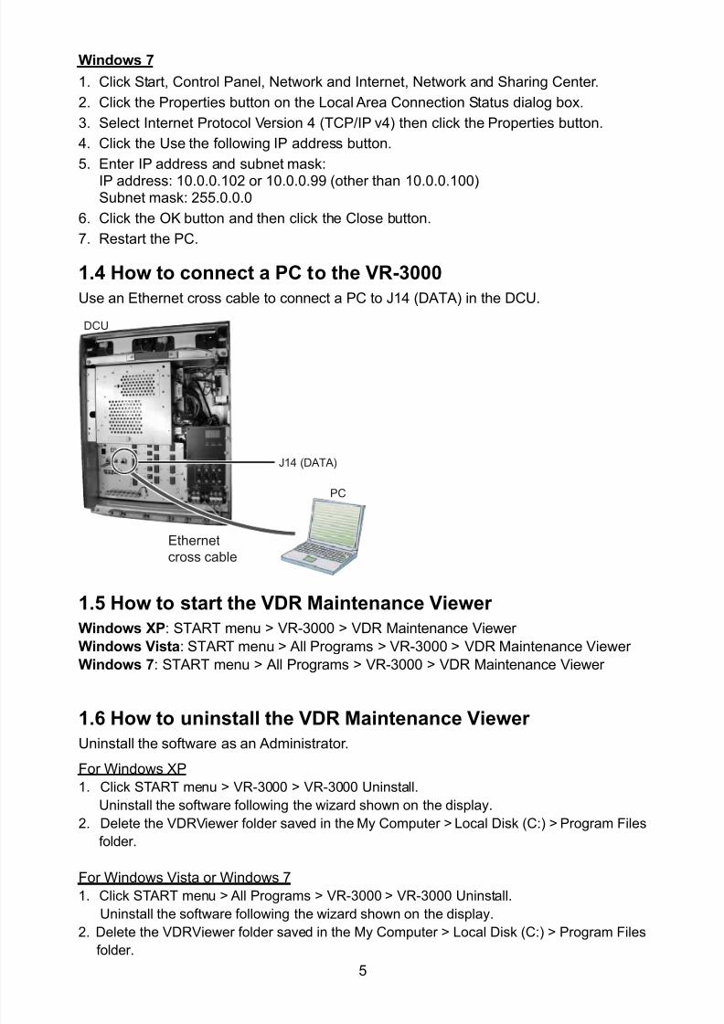
8102019 Ome44376d Vr3000 Mainte Cof26amp3bmol
httpslidepdfcomreaderfullome44376d-vr3000-mainte-cof26amp3bmol 757
5
Windows 7
1 Click Start Control Panel Network and Internet Network and Sharing Center
2 Click the Properties button on the Local Area Connection Status dialog box
3 Select Internet Protocol Version 4 (TCPIP v4) then click the Properties button
4 Click the Use the following IP address button
5 Enter IP address and subnet mask
IP address 1000102 or 100099 (other than 1000100)Subnet mask 255000
6 Click the OK button and then click the Close button
7 Restart the PC
14 How to connect a PC to the VR-3000
Use an Ethernet cross cable to connect a PC to J14 (DATA) in the DCU
Ethernetcross cable
DCU
PC
J14 (DATA)
15 How to start the VDR Maintenance Viewer
Windows XP START menu gt VR-3000 gt VDR Maintenance Viewer
Windows Vista START menu gt All Programs gt VR-3000 gt VDR Maintenance Viewer
Windows 7 START menu gt All Programs gt VR-3000 gt VDR Maintenance Viewer
16 How to uninstall the VDR Maintenance ViewerUninstall the software as an Administrator
For Windows XP
1 Click START menu gt VR-3000 gt VR-3000 Uninstall
Uninstall the software following the wizard shown on the display
2 Delete the VDRViewer folder saved in the My Computer gt Local Disk (C) gt Program Files
folder
For Windows Vista or Windows 7
1 Click START menu gt All Programs gt VR-3000 gt VR-3000 UninstallUninstall the software following the wizard shown on the display
2 Delete the VDRViewer folder saved in the My Computer gt Local Disk (C) gt Program Files
folder
8102019 Ome44376d Vr3000 Mainte Cof26amp3bmol
httpslidepdfcomreaderfullome44376d-vr3000-mainte-cof26amp3bmol 857
6
2 Software ConfigurationDisconnect the Remote Alarm Panel until the software configuration is completed
otherwise an alarm (grabber failure or no radar video) sounds
Procedure
1 In the Maintenance Viewer log in to Serviceman2 Download the configuration data from the VDR into the Maintenance Viewer
3 Set each tab (Refer from section 22 for further explanation)
4 After each tab has been set up save the data to the VDR
5 Lastly click the write button to backup the set data to the DRU Backup HDD and the CF
21 Preparing the software setup
To configure VR-3000VR-3000S software with the VDR Maintenance Viewer do the
following
1 Make sure that the PC and DRU are connected securely to the DCU2 Turn on the VDR and wait about three minutes
3 Download ldquoequipxmlrdquo from the VDR to the PC using the following steps
1 Open Internet Explorer on the PC
2 Enter the URL ftp1000100pub to access the VDR from the PC
3 Copy the file ldquoequipxmlrdquo and paste it onto the PC desktop
4 Start the VDR Maintenance Viewer
5 Enter the IP address1000100 in the Maintenance Login dialog box
6 Checkmark ldquoServicemanrdquo enter the password and click the OK button
Note Do not release the password to unauthorized personnel
If the connection is successful the information shown below appears in the status
window- System Time - RAP LEDs - POWER STATUS- DRU Information - Backup HDD Information
If an error message appears the IP address or password may be wrong or the cable
between the PC and VDR is not correctly connected
7 Check the memory size of the DRU and Backup HDD that appear in the status
window
If the memory size display shows MB (data read error) restart the VDR If the
display still does not change check that the DRU and HDD are correctly connected
8102019 Ome44376d Vr3000 Mainte Cof26amp3bmol
httpslidepdfcomreaderfullome44376d-vr3000-mainte-cof26amp3bmol 957
7
Example of acceptable memory size displays
Backup HDD InformationSelected AREA2Size 37864 MB
6GB DRU InformationSelected DRUSize 5794 MB or more
9GB DRU InformationSelected DRUSize 8822 MB or more
8 Select PC_RAP from the Tool menu
Confirm Alarm box in PC_RAP When a 3xx error is displayed as above the data is not
input correctly Data settings are explained on the page 12 If error messages 094 098
018 022 etc are displayed remove the error before going to the next step Refer to the
VDR Operatorrsquos Manual or error code list for definitions of the meanings of individual
error codes
9 Click the X button at the top right corner to close the PC_RAP
10 From the menu select Maintenancegt Equipment Managementgt Import
11 Select the file ldquoequipxmlrdquo from the desktop and click [open]
12 From the menu select Maintenancegt VDR Config Managementgt Download Click
the OK button and then [Close]
If the configuration file has already been downloaded the 12th step is not necessary
The following explanation refers to setting individual tabs
On the signal tab there is an Information Area (left) and a Setting Area (right) Select the
channel to set in the Information Area on the left by selecting it with the cursor and then
set it in the Setting Area on the right The results of the updated setting are displayed in
the Information Area After setting each channel click SET to finish
8102019 Ome44376d Vr3000 Mainte Cof26amp3bmol
httpslidepdfcomreaderfullome44376d-vr3000-mainte-cof26amp3bmol 1057
8
22 RadarRadar Setup is performed in the Radar Tab
Equipment Setup
1 Click the Radar tab
The Radar information setup screen appears
2 Select a radar channel from the Information area For example click the CH No1 boxto open the corresponding setup
3 Click the Select Equipment button in the Setting Area The following dialogue boxappears
4 Select a radar model
For example as in the above illustration select Radargt RadarInterfacegtFurunogtFAR-28x7gt SXGA(60Hz) and click the OK button As in thefollowing illustration FAR-28x7 appears in the Type No field in the CH No 1 of theInformation Area Detailed information about the selected radar appears in the Setting Area
8102019 Ome44376d Vr3000 Mainte Cof26amp3bmol
httpslidepdfcomreaderfullome44376d-vr3000-mainte-cof26amp3bmol 1157
9
If your radar model is not in the list enter the required information manually Thesetting values are the same as the previous Web Configuration values
5 Click the Image Capture button in the Setting Area Confirm the correct video signal6 If required update the Setting Area item contents
It is not necessary to enter information very every item in the Setting Area For easyidentification of Input Source enter Equipment Category Brand Type No and DataName
7 Click the Set button to finish
8 To setup multiple radars repeat steps 2 through 7
9 Click the Check button in the setting area to perform radar check Results appear inthe Check section of the Information Area
8102019 Ome44376d Vr3000 Mainte Cof26amp3bmol
httpslidepdfcomreaderfullome44376d-vr3000-mainte-cof26amp3bmol 1257
10
To import the exact settings to another ship save the settings of the device in the Setting Area to the PC database
1 Click on Reflect Equipment
2 Copy the file to the PC by using Maintenancegt Equipment Managementgt Export inthe menu
3 Import to the other shiprsquos VDR from the PC
How to Set the Record Pattern
When there are two or more Radar units connected to the VDR select which radar torecord to
Note When using a 6 GB DRU it possible to record to 1 channel and when using a 9 GBDRU it is possible to record to 2 channels
1 In the Setting Area click the Recording Mode button The following dialogue boxappears
R1-R4 1st Radar (CH No1)~4
th Radar (CH No4)
G Records signal to the youngest radar number in a group pattern (ex R1-R4 aregrouped) If the youngest number is inactive signal is recorded to the next youngestnumber in sequence within the group
I Indicated unit recordssends
N Indicated unit does not recordsend
2 Select a recording pattern from Patterns 1-4
For example the settings in the above illustration are as follows
Recording Pattern 1 R1 signal is recorded to DRU R2 ndash R4 do not record
R1 and R2 signals are recorded to the Backup HDD R3ndashR4 donot record
Network Sending R1-R4 all send to network
Recording Pattern 3 Recording signal to the DRU automatically routes to the nextyoungest active number in the group between R1 and R3 R4 Does not recordExample If R1 is inactive signal is recorded to R2
Recording to Backup HDD Same as DRU
Send to Network R1-R4 all is sent to the network
3 Update I and N as needed
8102019 Ome44376d Vr3000 Mainte Cof26amp3bmol
httpslidepdfcomreaderfullome44376d-vr3000-mainte-cof26amp3bmol 1357
11
Place the cursor above either I or N and left click to alternate With this I is set torecord while N is set to not record G cannot be changed
4 After completing setup click the OK button
5 To record settings to the database click Reflect Equipment in the Setting Area
How to Enter Information Manually
This VDR system receives in VESA (Video Electronics Standards Association) signal Image signal 05-1Vpp (When using composite signal the minimum synchronization
signal is 50 mV)
Horizontal Synchronization Signal Max plusmn91146 kHz
Vertical Synchronization Signal Max 35 Hz
Acceptable Image Resolution 640x480 ndash 1280x1024
Channel number conforms to the number displayed by the DCU
To set the Radar tab do the following
1 Click the Radar tab
2 Choose the channel with the entered Radar Image from the Information Area
3 Check the Active box in the Setting Area and enter the Horizontal and Verticalresolution of the incoming image in the Horizontal resolution and Vertical resolutioncolumns
4 Click the Set button
5 Click the Image Capturehellip button The Image Capture dialogue box appears
6 Click the Test button in the Image Capture window Radar image appears a fewseconds later
7 If the image is normal close the Image Capture window8 Input each item in the Setting Area
8102019 Ome44376d Vr3000 Mainte Cof26amp3bmol
httpslidepdfcomreaderfullome44376d-vr3000-mainte-cof26amp3bmol 1457
12
Items are as follows
Active Check a channel to activate it
Brand Enter brand nameType No Enter type noCheck Set and activate checkData Name Enter data nameHorizontal resolution Set horizontal resolutionVertical resolution Set vertical resolutionHorizontal Offset Move the picture horizontallyVertical offset Move the picture verticallyPLL This sets the frequency of the PLL-oscillatorCDEV Set CDEV
VCOSL Set VCO Signal LeadPhase (0-63) Phase setting selects the phase of the sampling clock relativeto phase locked loop signal in 64 steps of 5625 degrees IfPhase is not set correctly any section of an image consistingof vertical lines may show line ldquotearingrdquo
Sync Type Select the type of video sync signalHorizontal sync polarity Set the polarity of the horizontal sync signalVertical sync polarity Set the polarity of the vertical sync signalHDVD Sync Termination Sets horizontal and vertical synchronization point When
using a composite signal set to 75ohmsPulse Width for VD Detection (0-1020 Step4) Sets the pulse width for video signal
detectionInterlace Type When the video image is interlace set ldquoInterlaceldquo sampling
mode In Interlace mode the even pixels are sampled on oneframe and odd pixels are sampled on the other frame
8102019 Ome44376d Vr3000 Mainte Cof26amp3bmol
httpslidepdfcomreaderfullome44376d-vr3000-mainte-cof26amp3bmol 1557
13
Interlace Polarity Set interlace polarityITRP (0-4092 Step4) Enter interlace pulse positionITRW (0-4092 step4) Enter interlace pulse widthSampling Rate Display sampling rate Fixed at ldquo15 secondsrdquoCompress Type (viewer) Set compress type (viewer)Color Bit Display and set Color BitChange Pump Current Set pump current Fixed at ldquo05 mArdquo
Video Clock Polarity Set video clock polarity Fixed at ldquoThroughrdquoCounter Clock SelectionSelect counter clock selection Fixed at ldquo49 MHzrdquoVCO Clock Hold Sets VCO clock holdRed Gain (0-255) Enter red gainGreen Gain (0-255) Enter green gainBlue Gain (0-255) Enter blue gainRed Offset (0-255) Enter red offsetGreen Offset (0-255) Enter green offsetBlue Offset (0-255) Enter blue offsetBlack Level (0-255) Enter black levelEquipment Category Enter equipment category
Board Name Enter board name for corresponding channelNote Enter note
Note Offset Phase and Color Bit change with the length of the antenna cable
Marked Items For easy identification of input source enter Equipment Category Brand
Type No and Data Name
Measurement BoxThe Measurement Box is located on the left side of the Information Area The LOWHorizontal and Vertical counter should be higher than the HIGH counter If reversely the
HIGH counter is higher than the LOW counter it is possible that the SYNC Polaritysettings are adjusted incorrectly
8102019 Ome44376d Vr3000 Mainte Cof26amp3bmol
httpslidepdfcomreaderfullome44376d-vr3000-mainte-cof26amp3bmol 1657
14
Config Management
After all items have been set up proceed to the final setting management This can only
be executed one time after all tabs have been set up
1 Click on VDR Config Management in the Maintenance menu
2 Click on the Upload button to send all sent data to the VDR memory
3 Click each individual Write button to record to DRU Backup HDD and CF Note
If the settings are not uploaded to the VDR they have no effect on the unit
4 Click the Close button to close the VDR Config Management Dialogue Box
8102019 Ome44376d Vr3000 Mainte Cof26amp3bmol
httpslidepdfcomreaderfullome44376d-vr3000-mainte-cof26amp3bmol 1757
15
23 Serial Signal
The Serial tab sets the RS-422 signals received at the terminal board (SI01-SI08) and the
junction box (SI09-SI72) This channel is not only for NMEA but also binary and ASCII
data
Set the Serial tab as follows1 Click the Serial tab
2 Select a channel from the Information window
3 Click the Select Equipment button in the Setting Area
4 Choose the unit that is connected to the indicated Channel and click the OK Button
5 Adjust items as needed in the Setting Area
8102019 Ome44376d Vr3000 Mainte Cof26amp3bmol
httpslidepdfcomreaderfullome44376d-vr3000-mainte-cof26amp3bmol 1857
16
6 After finishing the settings for one channel click the Set buttonNote Be sure to do this before moving another channel
7 Repeat steps 2-6 to set up each channel
When running Config Management for Tab Settings
1 From the Maintenance menu click VDR Config Management and then Config
2 Click the Upload button to record data to the VDR memory3 Click the Write button to save data to the DRU backup HDD and CF
The buttons in the Setting Area are as followsSet Save edited dataCapture Received data shown in the serial window dialog boxSelect Equipment Select equipment settings (saved to the database) to reflect in
a channelReflect Equipment Save the equipment setting data to the databaseCheck Check all channels OK or NG (No Good) shown in
Information window
Individual Item ExplanationActive Put check in check box to make channel activeBrand Enter brand nameType No (Equipment Name) Set type no (equipment name)Check Do equipment checkData Name Enter data nameData Type Enter data typeBaud Rate Set baud rate (Available for SI01 to SI08)Data Bit Set number of bits (Available for SI01 to SI08)Parity Bit Set parity bit (Available for SI01 to SI08)Stop Bit Set stop bit (Available for SI01 to SI08)Source Checksum Enter checksum for GPS sourceTime out Set time outEquipment Category Set equipment categoryBoard Name Enter board names where channels are presentNote Enter note
Marked Items For easy identification of input source enter Equipment Category Brand
Type No Date and Name
8102019 Ome44376d Vr3000 Mainte Cof26amp3bmol
httpslidepdfcomreaderfullome44376d-vr3000-mainte-cof26amp3bmol 1957
17
24 Analog SignalAnalog signal is input via Junction Box IF-8530 (optional for VR-3000S)Receivable signal ndash10 to +10 V or 4 to 20mA
Connect the analog signal to V and G terminals on the Junction Box When 4 to 20 mAsignal is connected make a short circuit between the V and I input terminals with jumper
wireThe basic procedure for setting up the analog signal is as follows
1 Click the Analog tab
2 Select channel from the Information Area
3 Set detailed information of the selected channel in the Setting Area Refer to thefollowing illustration to enter detailed item information
In the factory settings there is no preset data when the Select Equipment button is
pressed In the case that the setup was completed on another ship and saved usingReflect Equipment import the data by clicking Select Equipment and choosing thesaved data
4 In the following order calibrate the Analog signal
① Click the Calibration button in the Setting Area
② Enter the voltage (or current) value for Calibration Point 1 and thecorresponding engineering value in the left and right boxes
③ Enter values for Calibration Point 2④ Enter unit for the values in Engineering Value Unit
8102019 Ome44376d Vr3000 Mainte Cof26amp3bmol
httpslidepdfcomreaderfullome44376d-vr3000-mainte-cof26amp3bmol 2057
18
In the above image the Engineering Value Unit is set to degrees (deg) TheCalibration Point 1 is -10V corresponding to 0 degrees Calibration Point 2 is10V corresponding to 30 degrees This is set corresponding to the connectedanalog sensor
When the Apply button is clicked the New Engineering Value of 29835Vcorresponding to the input Voltage of 989V is displayed in the bottom fieldWhenever the input value is changed this value also changes Check that theNew Engineering Value is within an appropriate range
Another method is to observe the Voltage (or Current) field in the top field andpress the Hold button of Point 1 when an appropriate value is displaying Dothis again for Point 2
⑤ Click the OK Button
5 When setting is complete click the Set button Be sure to do this before movinganother to channel
6 Repeat steps 1-5 to set up all channels
When using Config Manager with Tabs
1 From the Maintenance menu click VDR Config Management and then Config
2 Click the Upload button to record to VDR memory
3 Click the Write buttons to record to DRU Backup HDD and CF memory
The items in the Setting Area are as shown below Active Put check in check box to make channel activeBrand Enter brand name
Type No Set type no (equipment name)
Check Do equipment checkData Name Enter data nameData Type Analog Data type (0~10V -10~10v 4~20mV)
Sampling Rate Display sampling rateCalibration Active Disable and enable analog calibrationCalibration Point 1 Enter calibration point 1
Calibration Point 1 Value Enter calibration point 1 valueCalibration Point 2 Enter calibration point 2Calibration Point 2 Value Enter calibration point 2 valueEngineering Value Unit Enter engineering value unit
8102019 Ome44376d Vr3000 Mainte Cof26amp3bmol
httpslidepdfcomreaderfullome44376d-vr3000-mainte-cof26amp3bmol 2157
19
Note For -marked boxes values that are set at the Analog Calibration dialog box aredisplayed
Equipment Category Set equipment categoryBoard Name Enter board names where channels are presentNote Enter note
Marked Items For easy identification of input source enter Equipment CategoryBrand Type No Data and Name
25 Digital Signal
Digital signal is connected via Junction Box IF-8530 (optional for VR-3000S) The
receivable signal is 10-32 V for voltage signal or contact signal For voltage signal
connect to A and B input terminals on the Junction Box For contact signal connect to B
and G input terminals on the Junction Box Also make a short-circuit between the 24 and
A input terminals with a jumper wire
To set up the Digital tab
1 Click the Digital tab
2 Select a channel from the Information Area
3 Set up the digital signal from the Setting Area Refer to the following individual item
explanation
In the factory settings there is no preset data when the Select Equipment button is
pressed In the case that the setup was completed on another ship and saved using
Reflect Equipment import the data by clicking Select Equipment and choosing the
saved data
4 When setting Digital Signal to each 64 channel group perform the following
directions1 Click the Calibration button in the setting area
8102019 Ome44376d Vr3000 Mainte Cof26amp3bmol
httpslidepdfcomreaderfullome44376d-vr3000-mainte-cof26amp3bmol 2257
20
2 Check the active column of the channel group being set
3 Enter the status in columns 0 and 1 of that group
4 Click the OK Button
5 When finished setting up click the Set button
6 Repeat steps 2-5 to set up other channels
When using Config Manager with Tabs
1 From the Maintenance menu click VDR Config Management
2 Click the Upload button to record to VDR memory
3 Click the Write buttons to record to DRU Backup HDD and CF memory
The items in the Setting Area are as shown below
Active Put check in check box to make channel activeBrand Enter brand name
Type No Set type no (equipment name)Check Do equipment checkData Name Enter and display data nameContact Type Set contact type NO normal open NC normal closeSampling Rate Display sampling rateCalibration Active Disable and enable digital calibrationActive Status (1) Set status display when (1) is activeActive Status (0) Set status display when (0) is activeEquipment Category Set equipment categoryBoard Name Enter board names where channels are presentNote Enter note
Marked Items For easy identification of input source enter Equipment CategoryBrand Type No Date and Name
8102019 Ome44376d Vr3000 Mainte Cof26amp3bmol
httpslidepdfcomreaderfullome44376d-vr3000-mainte-cof26amp3bmol 2357
21
26 Audio
Microphone and VHF audio settings are performed in the Audio tab
Set the items in the Audio tab as shown below
1 Click the Audio tab
2 Select channel from the Information Area3 Click Select Equipment in the Setting Area
4 Click on the connected device in the indicated channel The setting contents aredisplayed in the Information and Setting Areas
5 If required update the item contents in the Setting Area Refer to the detailed itemexplanation below
6 After completing settings for a channel click the Set buttonNote Be sure to click the Set button before moving to another channel
7 Repeat steps 2-6 to set up other channels
8102019 Ome44376d Vr3000 Mainte Cof26amp3bmol
httpslidepdfcomreaderfullome44376d-vr3000-mainte-cof26amp3bmol 2457
22
When using Config Manager with tabs
1 From the Maintenance menu click VDR Config Management
2 Click the Upload button to record to VDR memory
3 Click the Write buttons to record to DRU Backup HDD and CF memory
MIC testDo the MIC test to check whether audio is received clearly in adequate level or not
1 Click the MIC TEST button in the Setting Area
2 Click the TEST button in the MIC Test dialogue box MIC test results are displayed in
the MIC Test dialogue box
3 Click the Close button to close the dialogue box
Note Not the same recordingplayback function as the previous Web Configuratorsoftware
Continuous MIC TestRun the continuous MIC test as needed accordingly
1 Click the Continuous MIC Test button in the Setting Area2 Set up how many times to perform in the Continuous MIC Test dialogue box and click
the Test button
3 Click the Close button to close the dialogue box
8102019 Ome44376d Vr3000 Mainte Cof26amp3bmol
httpslidepdfcomreaderfullome44376d-vr3000-mainte-cof26amp3bmol 2557
23
Active Put check in check box to make channel activeBrand Enter and display brand nameType No Set type no (equipment name)Check Do equipment checkData Name Enter data nameInput Type Enter input type Sampling Data Bit Displays sampling data bit rate
Sampling Frequency Displays Sampling FrequencyCodec Sets MIC typeMIC Test Active M1M3M5 Put a checkmark when performing MIC Test of M1M3M5MIS Test Active M2M4M6 Put a checkmark when performing MIC Test of M2M4M6 MIC M1M3M5 Position Enter MIC position of MIC M1M3M5MIC M2M4M6 Position Enter MIC position of MIC M2M4M6Threshold Level M1M3M5 Enter MIC test threshold level of MIC M1M3M5Threshold Level M2M4M6 Enter MIC test threshold level of MIC M2M4M6Equipment Category Set equipment categoryBoard Name Enter board names where channels are present
Note Enter note Marked Items For easy identification of input source enter Equipment Category BrandType No Date and Name
8102019 Ome44376d Vr3000 Mainte Cof26amp3bmol
httpslidepdfcomreaderfullome44376d-vr3000-mainte-cof26amp3bmol 2657
24
27 Alarm
Alarm and Alarm Status settings are found in the Alarm tab
The Alarm tab shows the following information about alarms Click the Time Categoryand Name tabs in the title bar to sort
Time Time of alarm
Category Alarm categoryName Name of alarm
Number Alarm number
Status Alarm status
Alarm Search
1 Click the Search button above the Alarm tab The Search dialogue box appears
2 Add a checkmark to any desired search items (multiple items can be selected)
Start Time Display name of alarms generated after a certain time
End Time Display name of alarms generated before a certain time
Name Display information for alarm name entered
8102019 Ome44376d Vr3000 Mainte Cof26amp3bmol
httpslidepdfcomreaderfullome44376d-vr3000-mainte-cof26amp3bmol 2757
25
Number Display information for alarm number entered
Status Display alarm status for alarm name entered
3 In the checked items column input the desired search items
4 Click the Search Button
Close the Search box to cancel a search
Note During a search the upper left Mode changes from Play to Search andDisplay search related information
8102019 Ome44376d Vr3000 Mainte Cof26amp3bmol
httpslidepdfcomreaderfullome44376d-vr3000-mainte-cof26amp3bmol 2857
26
28 Event
Click the items shown below to sort by item selected
Note You can sort the items in ascending order () descending order () and
initialization order (no symbol)
Time Time an event occurred
Category Category of an event
Name Name of an event
Contents1 Display data associated with log
Contents2 Display data associated with log
Event Search
Do the following to search events
1 Click the Search button on the upper right of the Event tab
2 In the dialogue box add a checkmark to desired search items Multiple items can bechecked
Start Time Display name of event generated after a certain time
End Time Display name of event generated before a certain time
Name Display event names entered
Number Display event numbers entered
Status Display event status entered
Enter information about the checked event to search in the character input box
3 Click the Search button
Note The mode changes from Play to Search when performing a search
8102019 Ome44376d Vr3000 Mainte Cof26amp3bmol
httpslidepdfcomreaderfullome44376d-vr3000-mainte-cof26amp3bmol 2957
27
29 Hardware
The Hardware tab provides information about the system hardware
The buttons in the Setting window work as follows
Self Check Status Display status of self check
CPU Display information about the CPU
Memory Size Display memory size
CPU Board Display status of CPU board
Audio Board Display status of Audio board
Serial Board Display status of Serial board
Radar Interface Board Display status of Radar Interface boardNote Enter and display note
Marked items are optional
8102019 Ome44376d Vr3000 Mainte Cof26amp3bmol
httpslidepdfcomreaderfullome44376d-vr3000-mainte-cof26amp3bmol 3057
28
210 JB
Connect the Junction Box to the DCU before turning on the system
The JB tab functions to set up the Junction Box
The basic procedure for setting up the Junction Box is as follows
1 Click the JB tab2 Select a Junction Box from the Information Area
3 Set up the Junction Box from the Setting Area
4 Click the Set button (Be sure to do this before moving to another channel)5 Click the Check button to perform an inspection on all channels In the Information
Area check column either OK or NG (No Good) is displayed
When using Config Manager with Tabs
1 From the Maintenance menu click VDR Config Management
2 Click the Upload button to record to VDR memory
3 Click the Write buttons to record to DRU Backup HDD and CF
The items in the Setting window work as followsActive Put check in check box to make channel activeNo Display Junction Box numberIP Address Display IP address of Junction Box acquired by VDRMAC Address Display MAC address of Junction Box acquired by VDRCheck Enable and disable equipment checkNote Enter note
Marked items are optional
8102019 Ome44376d Vr3000 Mainte Cof26amp3bmol
httpslidepdfcomreaderfullome44376d-vr3000-mainte-cof26amp3bmol 3157
29
211 Life Time
The Life Time tab controls consumable parts
The basic procedure for using the Life Time tab is as follows
1 Click the Life Time tab
2 Select a Type No in the Information Area3 Set up the chosen part from Setting Area
4 Click the Set button
Note Be sure to click the Set button before moving to set up a different Type
The items in the Setting window work as follows
Type No Enter and display type no
Data Name Enter and display data name
Level Set replacement level Legal Exchange Parts or Normal Exchange Parts
Replace Date Enter and display recommended day of replacement
Lifetime Term Not usedNote Enter and display note
The Status column of the Information Area displays as follows
OK The recommended date of replacement shown in the Replace Date
box in the Information window has not passed
Out of Date The date of replacement has passed
None The date of replacement has not been set
8102019 Ome44376d Vr3000 Mainte Cof26amp3bmol
httpslidepdfcomreaderfullome44376d-vr3000-mainte-cof26amp3bmol 3257
30
212 Network
The Network tab sets the system network
The basic procedure for setting up the system network is as follows
1 Click the Network tab
2 Select a port from the Information Area
3 Set up the network from the Setting Area
4 Click the Set button
Note1 Be sure to click the Set button before moving to set up a different Port
Note2 After setting the system network reboot the VDR to apply the settings
The items in the Setting window work as follows
LAN Type Enter LAN type Public LAN or JB LAN
MAC Address Enter MAC address
IP Address Enter IP address
Subnet Mask Enter subnet mask
Gateway Address Enter gateway address
Live Play Multicast Mode (Only JB LAN) Check box to enable live player multicast
mode
Multicast Address (Only Public LAN) Enter and display live player multicast addressNote Enter note
Marked items are optional
8102019 Ome44376d Vr3000 Mainte Cof26amp3bmol
httpslidepdfcomreaderfullome44376d-vr3000-mainte-cof26amp3bmol 3357
31
213 System
The System tab sets system related functions
The basic procedure for using the System tab is as follows
1 Click the System tab
2 Set up the chosen item from the Setting Area
3 Click the Set button
Note Be sure to click the Set button before moving to a different tab
The items in the Setting window work as follows
VDR Type Enter type of VDR
VDR Model Enter model number of VDR
Radar Interface Check Enable and disable checking of the Radar Interface board
Junction Box Count Enter number of junction boxes in system
DRU Flash Count Enter number of DRU flash disks in system Set 1 when DRU
serial no is 5000 and more Set 3 when DRU serial no is less
than 5000
DRU Capacity Display capacity of DRU
Backup HDD Capacity Display capacity of Backup HDD
VDR Config Version Display version no of VDR
VDR Config Date Display the number of hours the VDR settings have
been saved
VDR Config Code Display configuration identity code
Installation Engineer Enter name of the equipment installer
Installation Company Enter name of installers company
8102019 Ome44376d Vr3000 Mainte Cof26amp3bmol
httpslidepdfcomreaderfullome44376d-vr3000-mainte-cof26amp3bmol 3457
32
Installation Date Enter the date of the installation
MIC Test Time Enter the date of the MIC test
Note Enter note Marked items are optional
USB memory logging Do not check Enable
IEEE1394 BUS Error Auto Restart function Not used
IEEE1394 Active Node Count Do not change the default value of 3 (However set to 5
for serial number 5000 or less of DRU)
IEEE1394 Recover Process Limit Count Do not change the default value of 10
DRU Error Auto Restart function Not used
REBOOT DELAY TIME (sec) Do not change the default value of 10
LIMIT REBOOT COUNT Do not change the default value of 10
Live Player Max Connection Count The max number of Live Player V4 that can be
connected simultaneously The default no is two
but a maximum of five can be set here After you
change this option reboot the VDR to apply the
setting Disconnect the cable connected with
Live Player V4 (PC) from the VDR and thenreconnect it
214 Software
The Software tab sets and display software-related operations
The basic procedure for using the Software tab is as follows
1 Click the Software tab
2 Set up the chosen Item from the Setting Area
3 Click the Set button
8102019 Ome44376d Vr3000 Mainte Cof26amp3bmol
httpslidepdfcomreaderfullome44376d-vr3000-mainte-cof26amp3bmol 3557
33
The items in the Setting window work as follows
VDR System Program Display the VDR system program no
Process Version Display the process version
Power Distribution Unit (PDU) Display the version no of the PDU
Operation System Display the version no of the OS
Audio Driver Display the version no of the audio driverRAP Version Enter the version no of the RAP
AP Version Enter the version no of the AP
JB1-8 Boot Program Display the no of the RJB Boot program for Junction Boxes
1 to 8
JB1-8 App Program Display the no of the RJB App program for Junction Boxes
1 to 8
Watch Dog Interval Do not change the default value of 60 (Enter the process
response time A process is repeated if there is no response
within the time interval set here)
Giveup Interval Do not change the default value of 300 (Enter the restart
watch time The restarting of a process is stopped when the
number of times it has been restarted is exceeded within the
interval set here)
Refork Limit Do not change the default value of 10 (Enter the upper limit
for process restart The restarting of a process is stopped
when the number of times it has been restarted exceeds the
Give up Interval)
Note Enter note
Marked Items are optional
8102019 Ome44376d Vr3000 Mainte Cof26amp3bmol
httpslidepdfcomreaderfullome44376d-vr3000-mainte-cof26amp3bmol 3657
34
215 GPS
The GPS tab sets GPS-related parameters
The basic procedure for using the GPS tab is as follows
1 Click the GPS tab
2 Set up the chosen channel from the Information window3 Set up the chosen item in the Setting Area
4 Click the Set button
5 Repeat steps 2-4 to set up each Channel
6 Click the Check button to perform an inspection on all channels In the Information Area check column either OK or NG (No Good) is displayed
The items in the Setting window work as follows
Priority Display priority order
Date and Time SourceShip Position Source Set GPS source channel (serial channel
number for ZDA sentence)
Check Enable and disable checking
GPS Antenna Position From Bow Enter position of GPS antenna from bow
GPS Antenna Position From Stern Enter position of GPS antenna from stern
GPS Antenna Position From Port Enter position of GPS antenna from port
GPS Antenna Position From Starboard Enter position of GPS antenna from starboard
GPS Failure Threshold If the ZDA is input within the set time limit
the system restarts synchronized If not
input within the time limit the system restarts
without synchronization
8102019 Ome44376d Vr3000 Mainte Cof26amp3bmol
httpslidepdfcomreaderfullome44376d-vr3000-mainte-cof26amp3bmol 3757
35
GPS Delay Time by Time Sync Enter minimum time delay for time
synchronization Time synchronization is started
only in the time set here
GPS Difference Interval The time set here is added to the GPS time to
synchronize the system time Leave at the default
0 value setting
GPS Sync Giveup Time If the system receives the GPS time within the
time set the system synchronizes with the time
When not receiving a signal the system displays
an ldquoerror 26rdquo message
ZDA Timeout Enter value (seconds) for ZDA timeout (234 error)
from GPS
Note Enter and display note
Marked Items are optional
216 VesselThe Vessel tab sets and displays own ships information such as name and IMO number
The basic procedure for using the Vessel tab is as follows
1 Click the Vessel tab
2 Set up information in the Setting window
3 Click the Set button (Be sure to do this before moving to another port)
4 From the Maintenance menu click VDR Config Management and then Config5 Click the Write buttons to save data to the DRU backup HDD CF
The buttons in the Setting window works as follows
Vessel Name Enter name of vessel
Vessel IMO Number Enter IMO number of vessel
Vessel Flag Enter flag of vessel
Approval of Authority Enter name of approving authority
Note Enter note
Marked items are optional
8102019 Ome44376d Vr3000 Mainte Cof26amp3bmol
httpslidepdfcomreaderfullome44376d-vr3000-mainte-cof26amp3bmol 3857
36
217 Delivery
The Delivery tab functions to transmit data from the VDR to a PC via Ethernet LAN Do
not use this function during live connection
The basic procedure for using the Delivery tab is as follows
1 Click the Delivery tab
2 Click the Add button to show the Delivery Config window
3 Select protocol from the Protocol drop-down box (Unicast or Multicast)
4 Enter IP address in the IP address input box
5 Enter port number in the port number input box
6 Click the tab of the data to send (Analog Digital or Serial)
7 Select the channel of the data to send
8 If Serial was selected at step 6 select applicable data sentence from the Inactivewindow Click the right arrow to move the data sentence to the Active window
9 Click the OK button to close the Delivery Config window
10 The settings are listed in a table in the Delivery window Check the checkbox in the
Active column and then click the Set button
The buttons in the Setting window works as follows
Set Save edited settings
Add Create new delivery settings
Modify Modify selected delivery settings
Delete Delete selected delivery settings
8102019 Ome44376d Vr3000 Mainte Cof26amp3bmol
httpslidepdfcomreaderfullome44376d-vr3000-mainte-cof26amp3bmol 3957
37
3 How to Back up Configuration DataThis chapter shows how to back up configuration data to various storage media
Configuration data can be opened with Word Pad or any text editor other than Notepad
31 How to Back up Configuration Data to the Startup CompactFlash (CF)
Back up data to the startup CF after setting the VDR Configuration data is created on the
CF as a configini file
Note When the error shown below occurs during the downloading or uploading of
configuration data check the connection of the DRU Backup HDD and CF and then
upload or download the configuration data again
[CONN] Download failed
[CONN] Could not upload config file
If error occurs again re-install the VDR Maintenance Viewer
Do the following to back up data to a CF
1 Set up parameters on the tabs referring to Chapter 2
2 Click the Maintenance menu
3 Select VDR Config Management
4 Click the Upload button
5 A confirmation box appears click the OK button to start uploading to the VDR
6 Click the Write button where the arrow connects between VDR and DRU BackupHDD
7 A confirmation window appears click the OK button to save the configuration data tothe DRU and Backup HDD
8102019 Ome44376d Vr3000 Mainte Cof26amp3bmol
httpslidepdfcomreaderfullome44376d-vr3000-mainte-cof26amp3bmol 4057
38
8 Click the Write button where the arrow connects between the VDR and CF
9 A confirmation window appears click the OK button to save the configuration data tothe startup CF
10 Check that the PC VDR DRU Backup HDD and CF share the same VDR configcode
32 How to Back up Configuration Data to a PC
Configuration data saved to the PC can be edited with Wordpad and shared with other
vessels For future service ease it is recommended to backup configuration data to the
PC and have the data on board the vessel Also it is recommended to upload this data to
Furuno SMS (Service Management System) If unable to upload to Furuno SMS please
contact the Service Center Furuno Japan
To back up configuration data to the PC do as follows
1 Set up parameters on the tabs referring to Chapter 2
2 Click the Maintenance menu
3 Select VDR Config Management
4 Click the Export to button
5 A confirmation window appears click the OK button
6 Select where to save the data enter file name then click the Open button
7 Confirm that back up file is in the location selected
33 How to restore the default settings
Click the Default button on the VDR Config Management window to restore the default
settings of the DRU Backup HDD CF and VDR Maintenance Viewer
8102019 Ome44376d Vr3000 Mainte Cof26amp3bmol
httpslidepdfcomreaderfullome44376d-vr3000-mainte-cof26amp3bmol 4157
39
4 How to Upload Configuration Datafrom a PCThe procedure below shows how to upload configuration from the PC to aVR-3000VR-3000S
1 Click the Maintenance menu
2 Select VDR Config Management
3 Click the Import from button
4 The Open window appears Select configuration data and then click the Open button
5 Click the Upload button to upload data to the VR-3000VR-3000S
6 Click the Write buttons to save data to the DRU backup HDD and CF
8102019 Ome44376d Vr3000 Mainte Cof26amp3bmol
httpslidepdfcomreaderfullome44376d-vr3000-mainte-cof26amp3bmol 4257
40
5 Media ManagementThe media management feature deletes data from recording media initialization the
system etc There are two method LAN connection and Direct connection The Direct
connection takes longer time than the LAN connection Basically use the LAN connection
method
Note Initialization or creation of recording media is not available when Source Select onthe Live Player V4 is selected to Backup HDD
51 Initialization
This section shows how to delete data from the recording media Configuration data is
not deleted After performing the software configuration delete the data from the DRU
and HDD
Do the following to delete data from the DRU (LAN connection)
1 Set the PlaybackCPU switch in the DCU to the CPU position
2 Use an Ethernet cross cable to connect the PC to J14 (DATA) in the DCU (See page5)
3 Open the Tool menu
4 Select Media Management to open the VDR Media Management window
5 Check that IP address shown in the ldquoLAN Connect to IPrdquo in VDR Media Table Area isthe same as the IP address access point
6 Select ldquoLAN Connect to IPrdquo in the VDR Media Table column
8102019 Ome44376d Vr3000 Mainte Cof26amp3bmol
httpslidepdfcomreaderfullome44376d-vr3000-mainte-cof26amp3bmol 4357
41
7 Click the Analyze button A list of recording media connected to the VDR appears
Put a checkmark in the checkbox of the Select column for the DRU in the Name columnNote If there are several flash memories in the DRU all flash memories are shownCheck all flash memories shown
8 Select ldquoDRU Initializerdquo from the Operation dropdown list in the Operation area
10 Click the Run button
Do the following to delete data from the DRU (Direct connection)
1 Start Live Player V4 software
2 Open the Tool menu and select Source Select Select Live from the pull-downmenu
3 Click the Alarm tab and open Alarm History
4 Set the PlaybackCPU switch in the DCU to the Playback position
5 Wait approx 10 minutes and confirm that Alarm 174 occurs on Alarm History of LivePlayer V4
6 Connect an IEEEE1394 cable between J6 in the DCU and the PC
7 Open the Tool menu
8 Select Media Management to show the VDR Media Management window
9 Select Direct in the VDR Media Table column
10 Click the Analyze button A list of recording media connected to the VDR appears
11 Put a checkmark in the checkbox of the Select column for the DRU in the Namecolumn
Note If there are several flash memories in the DRU all flash memories are shownCheck all flash memories shown
12 Select ldquoDRU Initializerdquo from the Operation dropdown list in the Operation area
13 Enter password in the password column
14 Click the RUN button
8102019 Ome44376d Vr3000 Mainte Cof26amp3bmol
httpslidepdfcomreaderfullome44376d-vr3000-mainte-cof26amp3bmol 4457
42
Delete data from the Backup HDD as follows (LAN connection)
1 Set the PlaybackCPU switch in the DCU to the CPU position
2 Check that an Ethernet cross cable is connected between J14 in the DCU and the PC
3 Open the Tool menu
4 Select Media Management to open the VDR Media Management window
5 Check that IP address shown in the LAN Connect to IP in VDR Media Table Area is
the same as the IP address access point6 Select LAN Connect to IP in the VDR Media Table column
7 Click the Analyze button
8 A list of recording media connected to the VDR appears
9 Put a checkmark in the box of the Select column for the Backup HDD in the Namecolumn Select ldquoBackup HDD Initializerdquo from the Operation dropdown list in theOperation area
10 Click the Run button
Delete data from the Backup HDD as follows (Direct connection)
1 Start Live Player V4 software
2 Open the Tool menu and select Source Select Select Live from the pull-downmenu
3 Click the Alarm tab and open Alarm History
4 Set the PlaybackCPU switch in the DCU to the Playback position
5 Wait approx 10 minutes and confirm that Alarm 174 occurs on Alarm History of LivePlayer V4
6 Connect an IEEE1394 cable between J6 in the DCU and the PC
7 Open the Tool menu
8 Select Media Management to open the VDR Media Management window9 Select Direct in the VDR Media Table window
10 Click the Analyze button A list of recording media connected to the VDR appears
11 Put a checkmark in the check box of the Select column for the Backup HDD in theName column Select ldquoBackup HDD Initializerdquo from the Operation dropdown list in theOperation area
12 Enter password
13 Click the Run button
8102019 Ome44376d Vr3000 Mainte Cof26amp3bmol
httpslidepdfcomreaderfullome44376d-vr3000-mainte-cof26amp3bmol 4557
43
52 CreationThe Creation feature initializes recording media
Note1 This feature deletes ALL configuration data Backup all VDR configuration data
Note2 When you initialize medium that is a different format for the DRU or Backup HDDdelete all partitions with the disk management tool of Windows
Note3 When the Creation is failed try again If you can not initialize recording media tryunder condition as shown below
Do the Creation by the direct connection (When the Creation by the LAN
connection is failed)
Delete all partitions of the DRU or Backup HDD with the disk management tool of
Windows to do the Creation
If the Creation is still failed request service to repairreplace the DRU or Backup
HDD
Initialize the DRU as follows (LAN connection)
1 Set the PlaybackCPU switch in the DCU to the CPU position
2 Check that an Ethernet cross cable is connected between J14 in the DCU and the PC
3 Open the Tool menu
4 Select Media Management to open the VDR Media Management window
5 Check that IP address shown in the LAN Connect to IP in VDR Media Table Area isthe same as the IP address access point
6 Check ldquoLAN Connect to IPrdquo in the VDR Media Table column
7 Click the Analyze button A list of recording media connected to the VDR appears
8 Put a checkmark in the box of the Select column for the DRU in the Name column
Select ldquoDRU Creationrdquo from the Operation dropdown list in the Operation area
9 Click the Run button
Initialize the Backup HDD as follows (LAN connection)
1 To format the Backup HDD place a checkmark in the Select column of the listedrecord media in the Name column of the VDR Media Management dialogue box
2 From the Operation drop down list of the Operation area select ldquoBackup HDDCreation (Radar) or ldquoBackup HDD Creationrdquo
Two partition tools are available for the Backup HDD in the Media Management as
below
Backup HDD creation
This tool is used when the number of the SXGA video signal connected to the BackupHDD is the same as the DRU The same partition is created on both DRU and HDD
(1) When two SXGA video signals are recorded onto the HDD while 9-GB DRU isconnected
(2) When an SXGA video signal is recorded onto the HDD while 6-GB DRU isconnected
Backup HDD creation (radar)
This tool is used when two SXGA video signals are recorded onto the HDD with 6-GB
DRU connected The HDD has an area (radar) to record the second radar signal inaddition to the same partition as the DRU This tool cannot be used when 9-GB DRUis connected
3 Press the Run Button
8102019 Ome44376d Vr3000 Mainte Cof26amp3bmol
httpslidepdfcomreaderfullome44376d-vr3000-mainte-cof26amp3bmol 4657
44
Initialize the DRU as follows (Direct connection)
1 Start Live Player V4 software
2 Open the Tool menu and select Source Select Select Live from the pull-downmenu
3 Click the Alarm tab and open Alarm History
4 Set the PlaybackCPU switch in the DCU to the Playback position
5 Wait approx 10 minutes and confirm that Alarm 174 occurs on Alarm History of LivePlayer V4
6 Connect an IEEE1394 cable between J6 in the DCU and the PC
7 Open the Tool menu
8 Select Media Management to open the VDR Media Management window
9 Select Direct in the VDR Media Table window
10 Click the Analyze button A list of recording media connected to the VDR appears
11 Put a checkmark in the box of the Select column for the DRU and the desiredrecording media in the Name column In the Operation dropdown list of the Operationarea select ldquoDRU Creationrdquo
12 Enter password in the password column
13 Click the Run button
Initialize the Backup HDD as follows (Direct Connection)
1 To format the Backup HDD place a checkmark in the Select column of the listedrecord media in the Name column of the VDR Media Management dialogue box
2 From the Operation column of the Operation area select ldquoBackup HDD Creation(Radar) or ldquoBackup HDD Creationrdquo
Backup HDD creation
This tool is used when the number of the SXGA video signal connected to the BackupHDD is the same as the DRU The same partition is created on both DRU and HDD
(1) When two SXGA video signals are recorded onto the HDD while 9-GB DRU is
connected
(2) When an SXGA video signal is recorded onto the HDD while 6-GB DRU is
connected
Backup HDD creation (radar)
This tool is used when two SXGA video signals are recorded onto the HDD with 6-GBDRU connected The HDD has an area (radar) to record the second radar signal inaddition to the same partition as the DRU This tool cannot be used when 9-GB DRUis connected
3 Enter the password in the Password column
4 Press the Run Button
8102019 Ome44376d Vr3000 Mainte Cof26amp3bmol
httpslidepdfcomreaderfullome44376d-vr3000-mainte-cof26amp3bmol 4757
45
53 How to Enable Recording Area on the Backup HDD
This function enables writing over a recording area To prevent falsification of data all
recording areas must be saved otherwise this function is disabled To use this function push
the SAVE button Save the data before doing this procedure
Note Software version 135 or higher can enable writing over a recording area even if
all recording areas are not saved
Recording enable (LAN connection)
1 Set the PlaybackCPU switch in the DCU to the CPU position
2 Check that an Ethernet cross cable is connected between J14 in the DCU and the PC
3 Open the Tool menu
4 Select Media Management to open the VDR Media Management window
5 Check that IP address shown in the ldquoLAN Connect to IPrdquo in VDR Media Table Area isthe same as the IP address access point
6 Select ldquoLAN Connect to IPrdquo in the VDR Media Table column7 Click the Analyze button A list of recording media connected to the VDR appears
8 Put a checkmark in the box of the Select column for the Backup HDD in the Namecolumn
9 Select ldquoBackup HDD Recording Area Enablerdquo from the Operation dropdown list in theOperation area
10 Click the Run button
Recording enable (Direct connection)
1 Start Live Player V4 software
2 Open the Tool menu and select Source Select Select Live from the pull-down menu3 Click the Alarm tab and open Alarm History
4 Set the PlaybackCPU switch in the DCU to the Playback position
5 Wait approx 10 minutes and confirm that Alarm 174 occurs on Alarm History of LivePlayer V4
6 Connect an IEEE1394 cable between J6 in the DCU and the PC
7 Open the Tool menu
8 Select Media Management to open the VDR Media Management window
9 Select Direct in the VDR Media Table window
10 Click the Analyze button A list of recording media connected to the VDR appears11 Put a checkmark in the box of the Select column for the Backup HDD in the Name
column
12 Select ldquoBackup HDD Recording Area Enablerdquo from the Operation dropdown list in theOperation area
13 Enter password
14 Click the Run button
8102019 Ome44376d Vr3000 Mainte Cof26amp3bmol
httpslidepdfcomreaderfullome44376d-vr3000-mainte-cof26amp3bmol 4857
46
6 Other Functions
61 Software Management
The software download feature downloads VDR system software to the PC
To download software
1 Click the Maintenance menu
2 From the Software Management menu click Software Download to show theSoftware Download window
3 Enter the IP address 1000100 in the IP address box in the Update Server area
4 Click the Download Software button
5 The confirmation window appears click the OK button
The Software Backup Execute window shows the results of the download
Software is downloaded to C Program Files VDR Viewer Viewer Backup The software file
name is vdrtar
To Update Software
VDR system program version 16x can update the software with the procedure shownbelow
Note Do not update the file downloaded in procedures above
1 Click the Maintenance menu
2 From the Software Management menu click Software Upload to show the SoftwareUpload area
3 Click the Select button to show the Open window
4 Select update file (vdrtar) and click the Open button
8102019 Ome44376d Vr3000 Mainte Cof26amp3bmol
httpslidepdfcomreaderfullome44376d-vr3000-mainte-cof26amp3bmol 4957
47
5 Check the displayed Software information is correct
6 Enter the IP address 1000100 in the IP address box in the Update Server area
7 Enter password
8 Click the Update button
After the updating is completed the VDR is automatically restarted
Note Click the Restore button on the Software Update window to restore previoussoftware version This feature is available after updating the software
62 Password Management
The password can be changed for a serviceman to access the equipment Contact
FURUNO to get the default password to use during installation
Serviceman password
1 Click the Maintenance menu2 Select Change Serviceman Password from Password Management to show the
Change Serviceman Password window
3 Enter current password in the Old Password box
4 Enter the new password in the New Password box of the Change Password area
5 Enter new password again in the Confirm New Password box
6 Click the OK button
Audio password
The audio password set at the VDR Maintenance Viewer can be removed to enable
audio access without password1 Click the Maintenance menu
2 Select Change Audio Password from Password Management to show the Change Audio Password window
3 The confirmation window appears click the OK button
8102019 Ome44376d Vr3000 Mainte Cof26amp3bmol
httpslidepdfcomreaderfullome44376d-vr3000-mainte-cof26amp3bmol 5057
48
63 Record ComparisonThe integrity of the DRU and Backup HDD recordings can be compared This function isused by the RampD engineer for debugging
Follow the procedure as shown below
1 Click the Maintenance menu2 Select Record Comparison to show the Record Comparison window
The results are shown every 15 seconds in the Record Comparison window
8102019 Ome44376d Vr3000 Mainte Cof26amp3bmol
httpslidepdfcomreaderfullome44376d-vr3000-mainte-cof26amp3bmol 5157
49
64 Software History
This section shows you to save and configure software history (communications record)
How to save software history
Note When the error dialog appears while saving the software history restart the VDR
Maintenance Viewer
1 Click the Maintenance menu
2 Select Software History Collect
3 Click the Select button The Open dialog box appears
4 Select where to save the data then click the Open button
5 Select desired save condition then click the OK buttonNone No savingAt Once Save the software history manually Saving begins as soon as the OK button is clickedPeriodic For debugging Do not use otherwise The intervals are 30 sec 60 secand 120 secAlarm Detection For debugging Do not use otherwise Software history is savedwhen specified alarm is released Enter alarm number
How to configure software communications record
The RampD engineer uses this function for debugging Do not do this procedure unless
required Malfunction can result
1 Click the Maintenance menu
2 Select Software History Config
3 Do the followingProcess Select the type of communications record to save ALL saves allcommunications records
Detail Hide or show detailed information4 Click the Send button
8102019 Ome44376d Vr3000 Mainte Cof26amp3bmol
httpslidepdfcomreaderfullome44376d-vr3000-mainte-cof26amp3bmol 5257
50
65 Easy SetupThis feature sets equipment settings in batch and creates a data file of those settings
Default template The default template is created with the settings entered at installation
1 Click the Maintenance menu
2 Select Easy Setup to show the Template Selection window
3 Select Default Template
4 Click the Start button to show the Easy Setup window
5 Right click the channels (Radar Audio Digital Serial Analog) then select Edit toshow the Equipment Selection window
6 From the Equipment Directory window select equipment connected to the selectedchannel and then click the OK button
7 Repeat steps 5 and 6 to select equipment settings for each channel
8 Click the Save button in the Easy Setup window to show the Save window
9 Select where to save the file and enter file name
10 Click the Save button
8102019 Ome44376d Vr3000 Mainte Cof26amp3bmol
httpslidepdfcomreaderfullome44376d-vr3000-mainte-cof26amp3bmol 5357
51
Specific template Use a file already created
1 Click the Maintenance menu
2 Select Easy Setup to show the Template Selection window
3 Check Specified Template
4 Click the Select button and then select the file to edit
5 Click the Start button to show the Easy Setup window
6 Right click the channels (Radar Audio Digital Serial Analog) then select Edit toshow the Equipment Selection window
7 From the Equipment Directory window select equipment connected to the selectedchannel and then click the OK button
8 Repeat steps 6 and 7 to select equipment settings for each channel
9 Click the Save button in the Easy Setup window to show the Save window
10Select where to save the file and enter file name
11 Click the Save button
66 Equipment Management
This feature controls the import and export of equipment settings
Import data file
Import data files of equipment settings created in Easy Setup etc to the VDR
1 Click the Maintenance menu
2 Select Import from Equipment Management to show the Open window
3 Select the data file to import and click Open
Export data file
Export data files of equipment settings from the VDR to a PC
1 Click the Maintenance menu
2 Select Export from Equipment Management to show the Save window
3 Enter file name
4 Click the Save button
8102019 Ome44376d Vr3000 Mainte Cof26amp3bmol
httpslidepdfcomreaderfullome44376d-vr3000-mainte-cof26amp3bmol 5457
52
67 PC_RAP
This feature enables the same operation of the RAP (Remote Alarm Panel) from a PC
Select PC_RAP from the Tool menu to show the PC_RAP window
The buttons in the PC_RAP window function as shown below
SAVE Stop recording in the area where recording is currently being done
ACK Silence audio alarm
The PC_RAP display shows the following information with LEDs
RAP_LEDs Display the status of LEDs on the RAPSave The Save button blinks yellow when pushed When the 4 memory
areas have data recorded to them the Save button lights orange when
pushed
Normal Lights (green) where there are no unconfirmed or not restored
alarms
Error Flashes (red) for not confirmed alarm Lights (red) for unrestored
alarm
8102019 Ome44376d Vr3000 Mainte Cof26amp3bmol
httpslidepdfcomreaderfullome44376d-vr3000-mainte-cof26amp3bmol 5557
53
Backup HDD Information Display status of backup HDD
Selected Display current recording area and its status in green for
normal operation and in red for abnormal operation
Size Display capacity of backup HDD
Alarm area displays unconfirmed alarms
Time Display time alarm was generatedNumber Display number of alarm
Name Display name of alarm
Pending Alarm displays the unrestored alarms out of confirmed alarms only
Time Display time alarm was generated
Number Display number of alarm
Name Display name of alarm
8102019 Ome44376d Vr3000 Mainte Cof26amp3bmol
httpslidepdfcomreaderfullome44376d-vr3000-mainte-cof26amp3bmol 5657
54
68 Other
Status Monitor
The status monitor feature provides comprehensive data about the status of the VDR
From the menu bar click Toolgt Status Monitor to show the Status Monitor window
The buttons in the Status Monitor window work as shown below
Reload Settings for automatic refreshing of the status monitor
ON Turn automatic refresh OFF
OFF The Status Monitor is refreshed every five seconds
Save Available when Reload ON is selected The contents of the Status Monitor can be
saved to a text fileUpdate Update the Status Monitor display
Close Close the Status Monitor display
8102019 Ome44376d Vr3000 Mainte Cof26amp3bmol
httpslidepdfcomreaderfullome44376d-vr3000-mainte-cof26amp3bmol 5757
VDR Error List
This feature compiles all the errors shown on the RAP for easy reference
Access from MenugtToolgtVDR Error List
The VDR error list contains the following information
NO Display the number of the error
Title Display the name of the error
Detail Display details about the error
Exchange Check
This feature removes the alarms generated when replacing the DRU or backup HDD
Access MenugtToolgtExchange Check select either DRU or Backup HDD and click OK
Reboot
Reboot the VDR
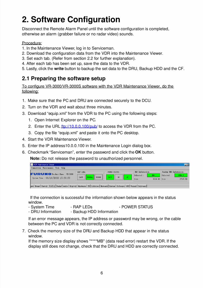
8102019 Ome44376d Vr3000 Mainte Cof26amp3bmol
httpslidepdfcomreaderfullome44376d-vr3000-mainte-cof26amp3bmol 857
6
2 Software ConfigurationDisconnect the Remote Alarm Panel until the software configuration is completed
otherwise an alarm (grabber failure or no radar video) sounds
Procedure
1 In the Maintenance Viewer log in to Serviceman2 Download the configuration data from the VDR into the Maintenance Viewer
3 Set each tab (Refer from section 22 for further explanation)
4 After each tab has been set up save the data to the VDR
5 Lastly click the write button to backup the set data to the DRU Backup HDD and the CF
21 Preparing the software setup
To configure VR-3000VR-3000S software with the VDR Maintenance Viewer do the
following
1 Make sure that the PC and DRU are connected securely to the DCU2 Turn on the VDR and wait about three minutes
3 Download ldquoequipxmlrdquo from the VDR to the PC using the following steps
1 Open Internet Explorer on the PC
2 Enter the URL ftp1000100pub to access the VDR from the PC
3 Copy the file ldquoequipxmlrdquo and paste it onto the PC desktop
4 Start the VDR Maintenance Viewer
5 Enter the IP address1000100 in the Maintenance Login dialog box
6 Checkmark ldquoServicemanrdquo enter the password and click the OK button
Note Do not release the password to unauthorized personnel
If the connection is successful the information shown below appears in the status
window- System Time - RAP LEDs - POWER STATUS- DRU Information - Backup HDD Information
If an error message appears the IP address or password may be wrong or the cable
between the PC and VDR is not correctly connected
7 Check the memory size of the DRU and Backup HDD that appear in the status
window
If the memory size display shows MB (data read error) restart the VDR If the
display still does not change check that the DRU and HDD are correctly connected
8102019 Ome44376d Vr3000 Mainte Cof26amp3bmol
httpslidepdfcomreaderfullome44376d-vr3000-mainte-cof26amp3bmol 957
7
Example of acceptable memory size displays
Backup HDD InformationSelected AREA2Size 37864 MB
6GB DRU InformationSelected DRUSize 5794 MB or more
9GB DRU InformationSelected DRUSize 8822 MB or more
8 Select PC_RAP from the Tool menu
Confirm Alarm box in PC_RAP When a 3xx error is displayed as above the data is not
input correctly Data settings are explained on the page 12 If error messages 094 098
018 022 etc are displayed remove the error before going to the next step Refer to the
VDR Operatorrsquos Manual or error code list for definitions of the meanings of individual
error codes
9 Click the X button at the top right corner to close the PC_RAP
10 From the menu select Maintenancegt Equipment Managementgt Import
11 Select the file ldquoequipxmlrdquo from the desktop and click [open]
12 From the menu select Maintenancegt VDR Config Managementgt Download Click
the OK button and then [Close]
If the configuration file has already been downloaded the 12th step is not necessary
The following explanation refers to setting individual tabs
On the signal tab there is an Information Area (left) and a Setting Area (right) Select the
channel to set in the Information Area on the left by selecting it with the cursor and then
set it in the Setting Area on the right The results of the updated setting are displayed in
the Information Area After setting each channel click SET to finish
8102019 Ome44376d Vr3000 Mainte Cof26amp3bmol
httpslidepdfcomreaderfullome44376d-vr3000-mainte-cof26amp3bmol 1057
8
22 RadarRadar Setup is performed in the Radar Tab
Equipment Setup
1 Click the Radar tab
The Radar information setup screen appears
2 Select a radar channel from the Information area For example click the CH No1 boxto open the corresponding setup
3 Click the Select Equipment button in the Setting Area The following dialogue boxappears
4 Select a radar model
For example as in the above illustration select Radargt RadarInterfacegtFurunogtFAR-28x7gt SXGA(60Hz) and click the OK button As in thefollowing illustration FAR-28x7 appears in the Type No field in the CH No 1 of theInformation Area Detailed information about the selected radar appears in the Setting Area
8102019 Ome44376d Vr3000 Mainte Cof26amp3bmol
httpslidepdfcomreaderfullome44376d-vr3000-mainte-cof26amp3bmol 1157
9
If your radar model is not in the list enter the required information manually Thesetting values are the same as the previous Web Configuration values
5 Click the Image Capture button in the Setting Area Confirm the correct video signal6 If required update the Setting Area item contents
It is not necessary to enter information very every item in the Setting Area For easyidentification of Input Source enter Equipment Category Brand Type No and DataName
7 Click the Set button to finish
8 To setup multiple radars repeat steps 2 through 7
9 Click the Check button in the setting area to perform radar check Results appear inthe Check section of the Information Area
8102019 Ome44376d Vr3000 Mainte Cof26amp3bmol
httpslidepdfcomreaderfullome44376d-vr3000-mainte-cof26amp3bmol 1257
10
To import the exact settings to another ship save the settings of the device in the Setting Area to the PC database
1 Click on Reflect Equipment
2 Copy the file to the PC by using Maintenancegt Equipment Managementgt Export inthe menu
3 Import to the other shiprsquos VDR from the PC
How to Set the Record Pattern
When there are two or more Radar units connected to the VDR select which radar torecord to
Note When using a 6 GB DRU it possible to record to 1 channel and when using a 9 GBDRU it is possible to record to 2 channels
1 In the Setting Area click the Recording Mode button The following dialogue boxappears
R1-R4 1st Radar (CH No1)~4
th Radar (CH No4)
G Records signal to the youngest radar number in a group pattern (ex R1-R4 aregrouped) If the youngest number is inactive signal is recorded to the next youngestnumber in sequence within the group
I Indicated unit recordssends
N Indicated unit does not recordsend
2 Select a recording pattern from Patterns 1-4
For example the settings in the above illustration are as follows
Recording Pattern 1 R1 signal is recorded to DRU R2 ndash R4 do not record
R1 and R2 signals are recorded to the Backup HDD R3ndashR4 donot record
Network Sending R1-R4 all send to network
Recording Pattern 3 Recording signal to the DRU automatically routes to the nextyoungest active number in the group between R1 and R3 R4 Does not recordExample If R1 is inactive signal is recorded to R2
Recording to Backup HDD Same as DRU
Send to Network R1-R4 all is sent to the network
3 Update I and N as needed
8102019 Ome44376d Vr3000 Mainte Cof26amp3bmol
httpslidepdfcomreaderfullome44376d-vr3000-mainte-cof26amp3bmol 1357
11
Place the cursor above either I or N and left click to alternate With this I is set torecord while N is set to not record G cannot be changed
4 After completing setup click the OK button
5 To record settings to the database click Reflect Equipment in the Setting Area
How to Enter Information Manually
This VDR system receives in VESA (Video Electronics Standards Association) signal Image signal 05-1Vpp (When using composite signal the minimum synchronization
signal is 50 mV)
Horizontal Synchronization Signal Max plusmn91146 kHz
Vertical Synchronization Signal Max 35 Hz
Acceptable Image Resolution 640x480 ndash 1280x1024
Channel number conforms to the number displayed by the DCU
To set the Radar tab do the following
1 Click the Radar tab
2 Choose the channel with the entered Radar Image from the Information Area
3 Check the Active box in the Setting Area and enter the Horizontal and Verticalresolution of the incoming image in the Horizontal resolution and Vertical resolutioncolumns
4 Click the Set button
5 Click the Image Capturehellip button The Image Capture dialogue box appears
6 Click the Test button in the Image Capture window Radar image appears a fewseconds later
7 If the image is normal close the Image Capture window8 Input each item in the Setting Area
8102019 Ome44376d Vr3000 Mainte Cof26amp3bmol
httpslidepdfcomreaderfullome44376d-vr3000-mainte-cof26amp3bmol 1457
12
Items are as follows
Active Check a channel to activate it
Brand Enter brand nameType No Enter type noCheck Set and activate checkData Name Enter data nameHorizontal resolution Set horizontal resolutionVertical resolution Set vertical resolutionHorizontal Offset Move the picture horizontallyVertical offset Move the picture verticallyPLL This sets the frequency of the PLL-oscillatorCDEV Set CDEV
VCOSL Set VCO Signal LeadPhase (0-63) Phase setting selects the phase of the sampling clock relativeto phase locked loop signal in 64 steps of 5625 degrees IfPhase is not set correctly any section of an image consistingof vertical lines may show line ldquotearingrdquo
Sync Type Select the type of video sync signalHorizontal sync polarity Set the polarity of the horizontal sync signalVertical sync polarity Set the polarity of the vertical sync signalHDVD Sync Termination Sets horizontal and vertical synchronization point When
using a composite signal set to 75ohmsPulse Width for VD Detection (0-1020 Step4) Sets the pulse width for video signal
detectionInterlace Type When the video image is interlace set ldquoInterlaceldquo sampling
mode In Interlace mode the even pixels are sampled on oneframe and odd pixels are sampled on the other frame
8102019 Ome44376d Vr3000 Mainte Cof26amp3bmol
httpslidepdfcomreaderfullome44376d-vr3000-mainte-cof26amp3bmol 1557
13
Interlace Polarity Set interlace polarityITRP (0-4092 Step4) Enter interlace pulse positionITRW (0-4092 step4) Enter interlace pulse widthSampling Rate Display sampling rate Fixed at ldquo15 secondsrdquoCompress Type (viewer) Set compress type (viewer)Color Bit Display and set Color BitChange Pump Current Set pump current Fixed at ldquo05 mArdquo
Video Clock Polarity Set video clock polarity Fixed at ldquoThroughrdquoCounter Clock SelectionSelect counter clock selection Fixed at ldquo49 MHzrdquoVCO Clock Hold Sets VCO clock holdRed Gain (0-255) Enter red gainGreen Gain (0-255) Enter green gainBlue Gain (0-255) Enter blue gainRed Offset (0-255) Enter red offsetGreen Offset (0-255) Enter green offsetBlue Offset (0-255) Enter blue offsetBlack Level (0-255) Enter black levelEquipment Category Enter equipment category
Board Name Enter board name for corresponding channelNote Enter note
Note Offset Phase and Color Bit change with the length of the antenna cable
Marked Items For easy identification of input source enter Equipment Category Brand
Type No and Data Name
Measurement BoxThe Measurement Box is located on the left side of the Information Area The LOWHorizontal and Vertical counter should be higher than the HIGH counter If reversely the
HIGH counter is higher than the LOW counter it is possible that the SYNC Polaritysettings are adjusted incorrectly
8102019 Ome44376d Vr3000 Mainte Cof26amp3bmol
httpslidepdfcomreaderfullome44376d-vr3000-mainte-cof26amp3bmol 1657
14
Config Management
After all items have been set up proceed to the final setting management This can only
be executed one time after all tabs have been set up
1 Click on VDR Config Management in the Maintenance menu
2 Click on the Upload button to send all sent data to the VDR memory
3 Click each individual Write button to record to DRU Backup HDD and CF Note
If the settings are not uploaded to the VDR they have no effect on the unit
4 Click the Close button to close the VDR Config Management Dialogue Box
8102019 Ome44376d Vr3000 Mainte Cof26amp3bmol
httpslidepdfcomreaderfullome44376d-vr3000-mainte-cof26amp3bmol 1757
15
23 Serial Signal
The Serial tab sets the RS-422 signals received at the terminal board (SI01-SI08) and the
junction box (SI09-SI72) This channel is not only for NMEA but also binary and ASCII
data
Set the Serial tab as follows1 Click the Serial tab
2 Select a channel from the Information window
3 Click the Select Equipment button in the Setting Area
4 Choose the unit that is connected to the indicated Channel and click the OK Button
5 Adjust items as needed in the Setting Area
8102019 Ome44376d Vr3000 Mainte Cof26amp3bmol
httpslidepdfcomreaderfullome44376d-vr3000-mainte-cof26amp3bmol 1857
16
6 After finishing the settings for one channel click the Set buttonNote Be sure to do this before moving another channel
7 Repeat steps 2-6 to set up each channel
When running Config Management for Tab Settings
1 From the Maintenance menu click VDR Config Management and then Config
2 Click the Upload button to record data to the VDR memory3 Click the Write button to save data to the DRU backup HDD and CF
The buttons in the Setting Area are as followsSet Save edited dataCapture Received data shown in the serial window dialog boxSelect Equipment Select equipment settings (saved to the database) to reflect in
a channelReflect Equipment Save the equipment setting data to the databaseCheck Check all channels OK or NG (No Good) shown in
Information window
Individual Item ExplanationActive Put check in check box to make channel activeBrand Enter brand nameType No (Equipment Name) Set type no (equipment name)Check Do equipment checkData Name Enter data nameData Type Enter data typeBaud Rate Set baud rate (Available for SI01 to SI08)Data Bit Set number of bits (Available for SI01 to SI08)Parity Bit Set parity bit (Available for SI01 to SI08)Stop Bit Set stop bit (Available for SI01 to SI08)Source Checksum Enter checksum for GPS sourceTime out Set time outEquipment Category Set equipment categoryBoard Name Enter board names where channels are presentNote Enter note
Marked Items For easy identification of input source enter Equipment Category Brand
Type No Date and Name
8102019 Ome44376d Vr3000 Mainte Cof26amp3bmol
httpslidepdfcomreaderfullome44376d-vr3000-mainte-cof26amp3bmol 1957
17
24 Analog SignalAnalog signal is input via Junction Box IF-8530 (optional for VR-3000S)Receivable signal ndash10 to +10 V or 4 to 20mA
Connect the analog signal to V and G terminals on the Junction Box When 4 to 20 mAsignal is connected make a short circuit between the V and I input terminals with jumper
wireThe basic procedure for setting up the analog signal is as follows
1 Click the Analog tab
2 Select channel from the Information Area
3 Set detailed information of the selected channel in the Setting Area Refer to thefollowing illustration to enter detailed item information
In the factory settings there is no preset data when the Select Equipment button is
pressed In the case that the setup was completed on another ship and saved usingReflect Equipment import the data by clicking Select Equipment and choosing thesaved data
4 In the following order calibrate the Analog signal
① Click the Calibration button in the Setting Area
② Enter the voltage (or current) value for Calibration Point 1 and thecorresponding engineering value in the left and right boxes
③ Enter values for Calibration Point 2④ Enter unit for the values in Engineering Value Unit
8102019 Ome44376d Vr3000 Mainte Cof26amp3bmol
httpslidepdfcomreaderfullome44376d-vr3000-mainte-cof26amp3bmol 2057
18
In the above image the Engineering Value Unit is set to degrees (deg) TheCalibration Point 1 is -10V corresponding to 0 degrees Calibration Point 2 is10V corresponding to 30 degrees This is set corresponding to the connectedanalog sensor
When the Apply button is clicked the New Engineering Value of 29835Vcorresponding to the input Voltage of 989V is displayed in the bottom fieldWhenever the input value is changed this value also changes Check that theNew Engineering Value is within an appropriate range
Another method is to observe the Voltage (or Current) field in the top field andpress the Hold button of Point 1 when an appropriate value is displaying Dothis again for Point 2
⑤ Click the OK Button
5 When setting is complete click the Set button Be sure to do this before movinganother to channel
6 Repeat steps 1-5 to set up all channels
When using Config Manager with Tabs
1 From the Maintenance menu click VDR Config Management and then Config
2 Click the Upload button to record to VDR memory
3 Click the Write buttons to record to DRU Backup HDD and CF memory
The items in the Setting Area are as shown below Active Put check in check box to make channel activeBrand Enter brand name
Type No Set type no (equipment name)
Check Do equipment checkData Name Enter data nameData Type Analog Data type (0~10V -10~10v 4~20mV)
Sampling Rate Display sampling rateCalibration Active Disable and enable analog calibrationCalibration Point 1 Enter calibration point 1
Calibration Point 1 Value Enter calibration point 1 valueCalibration Point 2 Enter calibration point 2Calibration Point 2 Value Enter calibration point 2 valueEngineering Value Unit Enter engineering value unit
8102019 Ome44376d Vr3000 Mainte Cof26amp3bmol
httpslidepdfcomreaderfullome44376d-vr3000-mainte-cof26amp3bmol 2157
19
Note For -marked boxes values that are set at the Analog Calibration dialog box aredisplayed
Equipment Category Set equipment categoryBoard Name Enter board names where channels are presentNote Enter note
Marked Items For easy identification of input source enter Equipment CategoryBrand Type No Data and Name
25 Digital Signal
Digital signal is connected via Junction Box IF-8530 (optional for VR-3000S) The
receivable signal is 10-32 V for voltage signal or contact signal For voltage signal
connect to A and B input terminals on the Junction Box For contact signal connect to B
and G input terminals on the Junction Box Also make a short-circuit between the 24 and
A input terminals with a jumper wire
To set up the Digital tab
1 Click the Digital tab
2 Select a channel from the Information Area
3 Set up the digital signal from the Setting Area Refer to the following individual item
explanation
In the factory settings there is no preset data when the Select Equipment button is
pressed In the case that the setup was completed on another ship and saved using
Reflect Equipment import the data by clicking Select Equipment and choosing the
saved data
4 When setting Digital Signal to each 64 channel group perform the following
directions1 Click the Calibration button in the setting area
8102019 Ome44376d Vr3000 Mainte Cof26amp3bmol
httpslidepdfcomreaderfullome44376d-vr3000-mainte-cof26amp3bmol 2257
20
2 Check the active column of the channel group being set
3 Enter the status in columns 0 and 1 of that group
4 Click the OK Button
5 When finished setting up click the Set button
6 Repeat steps 2-5 to set up other channels
When using Config Manager with Tabs
1 From the Maintenance menu click VDR Config Management
2 Click the Upload button to record to VDR memory
3 Click the Write buttons to record to DRU Backup HDD and CF memory
The items in the Setting Area are as shown below
Active Put check in check box to make channel activeBrand Enter brand name
Type No Set type no (equipment name)Check Do equipment checkData Name Enter and display data nameContact Type Set contact type NO normal open NC normal closeSampling Rate Display sampling rateCalibration Active Disable and enable digital calibrationActive Status (1) Set status display when (1) is activeActive Status (0) Set status display when (0) is activeEquipment Category Set equipment categoryBoard Name Enter board names where channels are presentNote Enter note
Marked Items For easy identification of input source enter Equipment CategoryBrand Type No Date and Name
8102019 Ome44376d Vr3000 Mainte Cof26amp3bmol
httpslidepdfcomreaderfullome44376d-vr3000-mainte-cof26amp3bmol 2357
21
26 Audio
Microphone and VHF audio settings are performed in the Audio tab
Set the items in the Audio tab as shown below
1 Click the Audio tab
2 Select channel from the Information Area3 Click Select Equipment in the Setting Area
4 Click on the connected device in the indicated channel The setting contents aredisplayed in the Information and Setting Areas
5 If required update the item contents in the Setting Area Refer to the detailed itemexplanation below
6 After completing settings for a channel click the Set buttonNote Be sure to click the Set button before moving to another channel
7 Repeat steps 2-6 to set up other channels
8102019 Ome44376d Vr3000 Mainte Cof26amp3bmol
httpslidepdfcomreaderfullome44376d-vr3000-mainte-cof26amp3bmol 2457
22
When using Config Manager with tabs
1 From the Maintenance menu click VDR Config Management
2 Click the Upload button to record to VDR memory
3 Click the Write buttons to record to DRU Backup HDD and CF memory
MIC testDo the MIC test to check whether audio is received clearly in adequate level or not
1 Click the MIC TEST button in the Setting Area
2 Click the TEST button in the MIC Test dialogue box MIC test results are displayed in
the MIC Test dialogue box
3 Click the Close button to close the dialogue box
Note Not the same recordingplayback function as the previous Web Configuratorsoftware
Continuous MIC TestRun the continuous MIC test as needed accordingly
1 Click the Continuous MIC Test button in the Setting Area2 Set up how many times to perform in the Continuous MIC Test dialogue box and click
the Test button
3 Click the Close button to close the dialogue box
8102019 Ome44376d Vr3000 Mainte Cof26amp3bmol
httpslidepdfcomreaderfullome44376d-vr3000-mainte-cof26amp3bmol 2557
23
Active Put check in check box to make channel activeBrand Enter and display brand nameType No Set type no (equipment name)Check Do equipment checkData Name Enter data nameInput Type Enter input type Sampling Data Bit Displays sampling data bit rate
Sampling Frequency Displays Sampling FrequencyCodec Sets MIC typeMIC Test Active M1M3M5 Put a checkmark when performing MIC Test of M1M3M5MIS Test Active M2M4M6 Put a checkmark when performing MIC Test of M2M4M6 MIC M1M3M5 Position Enter MIC position of MIC M1M3M5MIC M2M4M6 Position Enter MIC position of MIC M2M4M6Threshold Level M1M3M5 Enter MIC test threshold level of MIC M1M3M5Threshold Level M2M4M6 Enter MIC test threshold level of MIC M2M4M6Equipment Category Set equipment categoryBoard Name Enter board names where channels are present
Note Enter note Marked Items For easy identification of input source enter Equipment Category BrandType No Date and Name
8102019 Ome44376d Vr3000 Mainte Cof26amp3bmol
httpslidepdfcomreaderfullome44376d-vr3000-mainte-cof26amp3bmol 2657
24
27 Alarm
Alarm and Alarm Status settings are found in the Alarm tab
The Alarm tab shows the following information about alarms Click the Time Categoryand Name tabs in the title bar to sort
Time Time of alarm
Category Alarm categoryName Name of alarm
Number Alarm number
Status Alarm status
Alarm Search
1 Click the Search button above the Alarm tab The Search dialogue box appears
2 Add a checkmark to any desired search items (multiple items can be selected)
Start Time Display name of alarms generated after a certain time
End Time Display name of alarms generated before a certain time
Name Display information for alarm name entered
8102019 Ome44376d Vr3000 Mainte Cof26amp3bmol
httpslidepdfcomreaderfullome44376d-vr3000-mainte-cof26amp3bmol 2757
25
Number Display information for alarm number entered
Status Display alarm status for alarm name entered
3 In the checked items column input the desired search items
4 Click the Search Button
Close the Search box to cancel a search
Note During a search the upper left Mode changes from Play to Search andDisplay search related information
8102019 Ome44376d Vr3000 Mainte Cof26amp3bmol
httpslidepdfcomreaderfullome44376d-vr3000-mainte-cof26amp3bmol 2857
26
28 Event
Click the items shown below to sort by item selected
Note You can sort the items in ascending order () descending order () and
initialization order (no symbol)
Time Time an event occurred
Category Category of an event
Name Name of an event
Contents1 Display data associated with log
Contents2 Display data associated with log
Event Search
Do the following to search events
1 Click the Search button on the upper right of the Event tab
2 In the dialogue box add a checkmark to desired search items Multiple items can bechecked
Start Time Display name of event generated after a certain time
End Time Display name of event generated before a certain time
Name Display event names entered
Number Display event numbers entered
Status Display event status entered
Enter information about the checked event to search in the character input box
3 Click the Search button
Note The mode changes from Play to Search when performing a search
8102019 Ome44376d Vr3000 Mainte Cof26amp3bmol
httpslidepdfcomreaderfullome44376d-vr3000-mainte-cof26amp3bmol 2957
27
29 Hardware
The Hardware tab provides information about the system hardware
The buttons in the Setting window work as follows
Self Check Status Display status of self check
CPU Display information about the CPU
Memory Size Display memory size
CPU Board Display status of CPU board
Audio Board Display status of Audio board
Serial Board Display status of Serial board
Radar Interface Board Display status of Radar Interface boardNote Enter and display note
Marked items are optional
8102019 Ome44376d Vr3000 Mainte Cof26amp3bmol
httpslidepdfcomreaderfullome44376d-vr3000-mainte-cof26amp3bmol 3057
28
210 JB
Connect the Junction Box to the DCU before turning on the system
The JB tab functions to set up the Junction Box
The basic procedure for setting up the Junction Box is as follows
1 Click the JB tab2 Select a Junction Box from the Information Area
3 Set up the Junction Box from the Setting Area
4 Click the Set button (Be sure to do this before moving to another channel)5 Click the Check button to perform an inspection on all channels In the Information
Area check column either OK or NG (No Good) is displayed
When using Config Manager with Tabs
1 From the Maintenance menu click VDR Config Management
2 Click the Upload button to record to VDR memory
3 Click the Write buttons to record to DRU Backup HDD and CF
The items in the Setting window work as followsActive Put check in check box to make channel activeNo Display Junction Box numberIP Address Display IP address of Junction Box acquired by VDRMAC Address Display MAC address of Junction Box acquired by VDRCheck Enable and disable equipment checkNote Enter note
Marked items are optional
8102019 Ome44376d Vr3000 Mainte Cof26amp3bmol
httpslidepdfcomreaderfullome44376d-vr3000-mainte-cof26amp3bmol 3157
29
211 Life Time
The Life Time tab controls consumable parts
The basic procedure for using the Life Time tab is as follows
1 Click the Life Time tab
2 Select a Type No in the Information Area3 Set up the chosen part from Setting Area
4 Click the Set button
Note Be sure to click the Set button before moving to set up a different Type
The items in the Setting window work as follows
Type No Enter and display type no
Data Name Enter and display data name
Level Set replacement level Legal Exchange Parts or Normal Exchange Parts
Replace Date Enter and display recommended day of replacement
Lifetime Term Not usedNote Enter and display note
The Status column of the Information Area displays as follows
OK The recommended date of replacement shown in the Replace Date
box in the Information window has not passed
Out of Date The date of replacement has passed
None The date of replacement has not been set
8102019 Ome44376d Vr3000 Mainte Cof26amp3bmol
httpslidepdfcomreaderfullome44376d-vr3000-mainte-cof26amp3bmol 3257
30
212 Network
The Network tab sets the system network
The basic procedure for setting up the system network is as follows
1 Click the Network tab
2 Select a port from the Information Area
3 Set up the network from the Setting Area
4 Click the Set button
Note1 Be sure to click the Set button before moving to set up a different Port
Note2 After setting the system network reboot the VDR to apply the settings
The items in the Setting window work as follows
LAN Type Enter LAN type Public LAN or JB LAN
MAC Address Enter MAC address
IP Address Enter IP address
Subnet Mask Enter subnet mask
Gateway Address Enter gateway address
Live Play Multicast Mode (Only JB LAN) Check box to enable live player multicast
mode
Multicast Address (Only Public LAN) Enter and display live player multicast addressNote Enter note
Marked items are optional
8102019 Ome44376d Vr3000 Mainte Cof26amp3bmol
httpslidepdfcomreaderfullome44376d-vr3000-mainte-cof26amp3bmol 3357
31
213 System
The System tab sets system related functions
The basic procedure for using the System tab is as follows
1 Click the System tab
2 Set up the chosen item from the Setting Area
3 Click the Set button
Note Be sure to click the Set button before moving to a different tab
The items in the Setting window work as follows
VDR Type Enter type of VDR
VDR Model Enter model number of VDR
Radar Interface Check Enable and disable checking of the Radar Interface board
Junction Box Count Enter number of junction boxes in system
DRU Flash Count Enter number of DRU flash disks in system Set 1 when DRU
serial no is 5000 and more Set 3 when DRU serial no is less
than 5000
DRU Capacity Display capacity of DRU
Backup HDD Capacity Display capacity of Backup HDD
VDR Config Version Display version no of VDR
VDR Config Date Display the number of hours the VDR settings have
been saved
VDR Config Code Display configuration identity code
Installation Engineer Enter name of the equipment installer
Installation Company Enter name of installers company
8102019 Ome44376d Vr3000 Mainte Cof26amp3bmol
httpslidepdfcomreaderfullome44376d-vr3000-mainte-cof26amp3bmol 3457
32
Installation Date Enter the date of the installation
MIC Test Time Enter the date of the MIC test
Note Enter note Marked items are optional
USB memory logging Do not check Enable
IEEE1394 BUS Error Auto Restart function Not used
IEEE1394 Active Node Count Do not change the default value of 3 (However set to 5
for serial number 5000 or less of DRU)
IEEE1394 Recover Process Limit Count Do not change the default value of 10
DRU Error Auto Restart function Not used
REBOOT DELAY TIME (sec) Do not change the default value of 10
LIMIT REBOOT COUNT Do not change the default value of 10
Live Player Max Connection Count The max number of Live Player V4 that can be
connected simultaneously The default no is two
but a maximum of five can be set here After you
change this option reboot the VDR to apply the
setting Disconnect the cable connected with
Live Player V4 (PC) from the VDR and thenreconnect it
214 Software
The Software tab sets and display software-related operations
The basic procedure for using the Software tab is as follows
1 Click the Software tab
2 Set up the chosen Item from the Setting Area
3 Click the Set button
8102019 Ome44376d Vr3000 Mainte Cof26amp3bmol
httpslidepdfcomreaderfullome44376d-vr3000-mainte-cof26amp3bmol 3557
33
The items in the Setting window work as follows
VDR System Program Display the VDR system program no
Process Version Display the process version
Power Distribution Unit (PDU) Display the version no of the PDU
Operation System Display the version no of the OS
Audio Driver Display the version no of the audio driverRAP Version Enter the version no of the RAP
AP Version Enter the version no of the AP
JB1-8 Boot Program Display the no of the RJB Boot program for Junction Boxes
1 to 8
JB1-8 App Program Display the no of the RJB App program for Junction Boxes
1 to 8
Watch Dog Interval Do not change the default value of 60 (Enter the process
response time A process is repeated if there is no response
within the time interval set here)
Giveup Interval Do not change the default value of 300 (Enter the restart
watch time The restarting of a process is stopped when the
number of times it has been restarted is exceeded within the
interval set here)
Refork Limit Do not change the default value of 10 (Enter the upper limit
for process restart The restarting of a process is stopped
when the number of times it has been restarted exceeds the
Give up Interval)
Note Enter note
Marked Items are optional
8102019 Ome44376d Vr3000 Mainte Cof26amp3bmol
httpslidepdfcomreaderfullome44376d-vr3000-mainte-cof26amp3bmol 3657
34
215 GPS
The GPS tab sets GPS-related parameters
The basic procedure for using the GPS tab is as follows
1 Click the GPS tab
2 Set up the chosen channel from the Information window3 Set up the chosen item in the Setting Area
4 Click the Set button
5 Repeat steps 2-4 to set up each Channel
6 Click the Check button to perform an inspection on all channels In the Information Area check column either OK or NG (No Good) is displayed
The items in the Setting window work as follows
Priority Display priority order
Date and Time SourceShip Position Source Set GPS source channel (serial channel
number for ZDA sentence)
Check Enable and disable checking
GPS Antenna Position From Bow Enter position of GPS antenna from bow
GPS Antenna Position From Stern Enter position of GPS antenna from stern
GPS Antenna Position From Port Enter position of GPS antenna from port
GPS Antenna Position From Starboard Enter position of GPS antenna from starboard
GPS Failure Threshold If the ZDA is input within the set time limit
the system restarts synchronized If not
input within the time limit the system restarts
without synchronization
8102019 Ome44376d Vr3000 Mainte Cof26amp3bmol
httpslidepdfcomreaderfullome44376d-vr3000-mainte-cof26amp3bmol 3757
35
GPS Delay Time by Time Sync Enter minimum time delay for time
synchronization Time synchronization is started
only in the time set here
GPS Difference Interval The time set here is added to the GPS time to
synchronize the system time Leave at the default
0 value setting
GPS Sync Giveup Time If the system receives the GPS time within the
time set the system synchronizes with the time
When not receiving a signal the system displays
an ldquoerror 26rdquo message
ZDA Timeout Enter value (seconds) for ZDA timeout (234 error)
from GPS
Note Enter and display note
Marked Items are optional
216 VesselThe Vessel tab sets and displays own ships information such as name and IMO number
The basic procedure for using the Vessel tab is as follows
1 Click the Vessel tab
2 Set up information in the Setting window
3 Click the Set button (Be sure to do this before moving to another port)
4 From the Maintenance menu click VDR Config Management and then Config5 Click the Write buttons to save data to the DRU backup HDD CF
The buttons in the Setting window works as follows
Vessel Name Enter name of vessel
Vessel IMO Number Enter IMO number of vessel
Vessel Flag Enter flag of vessel
Approval of Authority Enter name of approving authority
Note Enter note
Marked items are optional
8102019 Ome44376d Vr3000 Mainte Cof26amp3bmol
httpslidepdfcomreaderfullome44376d-vr3000-mainte-cof26amp3bmol 3857
36
217 Delivery
The Delivery tab functions to transmit data from the VDR to a PC via Ethernet LAN Do
not use this function during live connection
The basic procedure for using the Delivery tab is as follows
1 Click the Delivery tab
2 Click the Add button to show the Delivery Config window
3 Select protocol from the Protocol drop-down box (Unicast or Multicast)
4 Enter IP address in the IP address input box
5 Enter port number in the port number input box
6 Click the tab of the data to send (Analog Digital or Serial)
7 Select the channel of the data to send
8 If Serial was selected at step 6 select applicable data sentence from the Inactivewindow Click the right arrow to move the data sentence to the Active window
9 Click the OK button to close the Delivery Config window
10 The settings are listed in a table in the Delivery window Check the checkbox in the
Active column and then click the Set button
The buttons in the Setting window works as follows
Set Save edited settings
Add Create new delivery settings
Modify Modify selected delivery settings
Delete Delete selected delivery settings
8102019 Ome44376d Vr3000 Mainte Cof26amp3bmol
httpslidepdfcomreaderfullome44376d-vr3000-mainte-cof26amp3bmol 3957
37
3 How to Back up Configuration DataThis chapter shows how to back up configuration data to various storage media
Configuration data can be opened with Word Pad or any text editor other than Notepad
31 How to Back up Configuration Data to the Startup CompactFlash (CF)
Back up data to the startup CF after setting the VDR Configuration data is created on the
CF as a configini file
Note When the error shown below occurs during the downloading or uploading of
configuration data check the connection of the DRU Backup HDD and CF and then
upload or download the configuration data again
[CONN] Download failed
[CONN] Could not upload config file
If error occurs again re-install the VDR Maintenance Viewer
Do the following to back up data to a CF
1 Set up parameters on the tabs referring to Chapter 2
2 Click the Maintenance menu
3 Select VDR Config Management
4 Click the Upload button
5 A confirmation box appears click the OK button to start uploading to the VDR
6 Click the Write button where the arrow connects between VDR and DRU BackupHDD
7 A confirmation window appears click the OK button to save the configuration data tothe DRU and Backup HDD
8102019 Ome44376d Vr3000 Mainte Cof26amp3bmol
httpslidepdfcomreaderfullome44376d-vr3000-mainte-cof26amp3bmol 4057
38
8 Click the Write button where the arrow connects between the VDR and CF
9 A confirmation window appears click the OK button to save the configuration data tothe startup CF
10 Check that the PC VDR DRU Backup HDD and CF share the same VDR configcode
32 How to Back up Configuration Data to a PC
Configuration data saved to the PC can be edited with Wordpad and shared with other
vessels For future service ease it is recommended to backup configuration data to the
PC and have the data on board the vessel Also it is recommended to upload this data to
Furuno SMS (Service Management System) If unable to upload to Furuno SMS please
contact the Service Center Furuno Japan
To back up configuration data to the PC do as follows
1 Set up parameters on the tabs referring to Chapter 2
2 Click the Maintenance menu
3 Select VDR Config Management
4 Click the Export to button
5 A confirmation window appears click the OK button
6 Select where to save the data enter file name then click the Open button
7 Confirm that back up file is in the location selected
33 How to restore the default settings
Click the Default button on the VDR Config Management window to restore the default
settings of the DRU Backup HDD CF and VDR Maintenance Viewer
8102019 Ome44376d Vr3000 Mainte Cof26amp3bmol
httpslidepdfcomreaderfullome44376d-vr3000-mainte-cof26amp3bmol 4157
39
4 How to Upload Configuration Datafrom a PCThe procedure below shows how to upload configuration from the PC to aVR-3000VR-3000S
1 Click the Maintenance menu
2 Select VDR Config Management
3 Click the Import from button
4 The Open window appears Select configuration data and then click the Open button
5 Click the Upload button to upload data to the VR-3000VR-3000S
6 Click the Write buttons to save data to the DRU backup HDD and CF
8102019 Ome44376d Vr3000 Mainte Cof26amp3bmol
httpslidepdfcomreaderfullome44376d-vr3000-mainte-cof26amp3bmol 4257
40
5 Media ManagementThe media management feature deletes data from recording media initialization the
system etc There are two method LAN connection and Direct connection The Direct
connection takes longer time than the LAN connection Basically use the LAN connection
method
Note Initialization or creation of recording media is not available when Source Select onthe Live Player V4 is selected to Backup HDD
51 Initialization
This section shows how to delete data from the recording media Configuration data is
not deleted After performing the software configuration delete the data from the DRU
and HDD
Do the following to delete data from the DRU (LAN connection)
1 Set the PlaybackCPU switch in the DCU to the CPU position
2 Use an Ethernet cross cable to connect the PC to J14 (DATA) in the DCU (See page5)
3 Open the Tool menu
4 Select Media Management to open the VDR Media Management window
5 Check that IP address shown in the ldquoLAN Connect to IPrdquo in VDR Media Table Area isthe same as the IP address access point
6 Select ldquoLAN Connect to IPrdquo in the VDR Media Table column
8102019 Ome44376d Vr3000 Mainte Cof26amp3bmol
httpslidepdfcomreaderfullome44376d-vr3000-mainte-cof26amp3bmol 4357
41
7 Click the Analyze button A list of recording media connected to the VDR appears
Put a checkmark in the checkbox of the Select column for the DRU in the Name columnNote If there are several flash memories in the DRU all flash memories are shownCheck all flash memories shown
8 Select ldquoDRU Initializerdquo from the Operation dropdown list in the Operation area
10 Click the Run button
Do the following to delete data from the DRU (Direct connection)
1 Start Live Player V4 software
2 Open the Tool menu and select Source Select Select Live from the pull-downmenu
3 Click the Alarm tab and open Alarm History
4 Set the PlaybackCPU switch in the DCU to the Playback position
5 Wait approx 10 minutes and confirm that Alarm 174 occurs on Alarm History of LivePlayer V4
6 Connect an IEEEE1394 cable between J6 in the DCU and the PC
7 Open the Tool menu
8 Select Media Management to show the VDR Media Management window
9 Select Direct in the VDR Media Table column
10 Click the Analyze button A list of recording media connected to the VDR appears
11 Put a checkmark in the checkbox of the Select column for the DRU in the Namecolumn
Note If there are several flash memories in the DRU all flash memories are shownCheck all flash memories shown
12 Select ldquoDRU Initializerdquo from the Operation dropdown list in the Operation area
13 Enter password in the password column
14 Click the RUN button
8102019 Ome44376d Vr3000 Mainte Cof26amp3bmol
httpslidepdfcomreaderfullome44376d-vr3000-mainte-cof26amp3bmol 4457
42
Delete data from the Backup HDD as follows (LAN connection)
1 Set the PlaybackCPU switch in the DCU to the CPU position
2 Check that an Ethernet cross cable is connected between J14 in the DCU and the PC
3 Open the Tool menu
4 Select Media Management to open the VDR Media Management window
5 Check that IP address shown in the LAN Connect to IP in VDR Media Table Area is
the same as the IP address access point6 Select LAN Connect to IP in the VDR Media Table column
7 Click the Analyze button
8 A list of recording media connected to the VDR appears
9 Put a checkmark in the box of the Select column for the Backup HDD in the Namecolumn Select ldquoBackup HDD Initializerdquo from the Operation dropdown list in theOperation area
10 Click the Run button
Delete data from the Backup HDD as follows (Direct connection)
1 Start Live Player V4 software
2 Open the Tool menu and select Source Select Select Live from the pull-downmenu
3 Click the Alarm tab and open Alarm History
4 Set the PlaybackCPU switch in the DCU to the Playback position
5 Wait approx 10 minutes and confirm that Alarm 174 occurs on Alarm History of LivePlayer V4
6 Connect an IEEE1394 cable between J6 in the DCU and the PC
7 Open the Tool menu
8 Select Media Management to open the VDR Media Management window9 Select Direct in the VDR Media Table window
10 Click the Analyze button A list of recording media connected to the VDR appears
11 Put a checkmark in the check box of the Select column for the Backup HDD in theName column Select ldquoBackup HDD Initializerdquo from the Operation dropdown list in theOperation area
12 Enter password
13 Click the Run button
8102019 Ome44376d Vr3000 Mainte Cof26amp3bmol
httpslidepdfcomreaderfullome44376d-vr3000-mainte-cof26amp3bmol 4557
43
52 CreationThe Creation feature initializes recording media
Note1 This feature deletes ALL configuration data Backup all VDR configuration data
Note2 When you initialize medium that is a different format for the DRU or Backup HDDdelete all partitions with the disk management tool of Windows
Note3 When the Creation is failed try again If you can not initialize recording media tryunder condition as shown below
Do the Creation by the direct connection (When the Creation by the LAN
connection is failed)
Delete all partitions of the DRU or Backup HDD with the disk management tool of
Windows to do the Creation
If the Creation is still failed request service to repairreplace the DRU or Backup
HDD
Initialize the DRU as follows (LAN connection)
1 Set the PlaybackCPU switch in the DCU to the CPU position
2 Check that an Ethernet cross cable is connected between J14 in the DCU and the PC
3 Open the Tool menu
4 Select Media Management to open the VDR Media Management window
5 Check that IP address shown in the LAN Connect to IP in VDR Media Table Area isthe same as the IP address access point
6 Check ldquoLAN Connect to IPrdquo in the VDR Media Table column
7 Click the Analyze button A list of recording media connected to the VDR appears
8 Put a checkmark in the box of the Select column for the DRU in the Name column
Select ldquoDRU Creationrdquo from the Operation dropdown list in the Operation area
9 Click the Run button
Initialize the Backup HDD as follows (LAN connection)
1 To format the Backup HDD place a checkmark in the Select column of the listedrecord media in the Name column of the VDR Media Management dialogue box
2 From the Operation drop down list of the Operation area select ldquoBackup HDDCreation (Radar) or ldquoBackup HDD Creationrdquo
Two partition tools are available for the Backup HDD in the Media Management as
below
Backup HDD creation
This tool is used when the number of the SXGA video signal connected to the BackupHDD is the same as the DRU The same partition is created on both DRU and HDD
(1) When two SXGA video signals are recorded onto the HDD while 9-GB DRU isconnected
(2) When an SXGA video signal is recorded onto the HDD while 6-GB DRU isconnected
Backup HDD creation (radar)
This tool is used when two SXGA video signals are recorded onto the HDD with 6-GB
DRU connected The HDD has an area (radar) to record the second radar signal inaddition to the same partition as the DRU This tool cannot be used when 9-GB DRUis connected
3 Press the Run Button
8102019 Ome44376d Vr3000 Mainte Cof26amp3bmol
httpslidepdfcomreaderfullome44376d-vr3000-mainte-cof26amp3bmol 4657
44
Initialize the DRU as follows (Direct connection)
1 Start Live Player V4 software
2 Open the Tool menu and select Source Select Select Live from the pull-downmenu
3 Click the Alarm tab and open Alarm History
4 Set the PlaybackCPU switch in the DCU to the Playback position
5 Wait approx 10 minutes and confirm that Alarm 174 occurs on Alarm History of LivePlayer V4
6 Connect an IEEE1394 cable between J6 in the DCU and the PC
7 Open the Tool menu
8 Select Media Management to open the VDR Media Management window
9 Select Direct in the VDR Media Table window
10 Click the Analyze button A list of recording media connected to the VDR appears
11 Put a checkmark in the box of the Select column for the DRU and the desiredrecording media in the Name column In the Operation dropdown list of the Operationarea select ldquoDRU Creationrdquo
12 Enter password in the password column
13 Click the Run button
Initialize the Backup HDD as follows (Direct Connection)
1 To format the Backup HDD place a checkmark in the Select column of the listedrecord media in the Name column of the VDR Media Management dialogue box
2 From the Operation column of the Operation area select ldquoBackup HDD Creation(Radar) or ldquoBackup HDD Creationrdquo
Backup HDD creation
This tool is used when the number of the SXGA video signal connected to the BackupHDD is the same as the DRU The same partition is created on both DRU and HDD
(1) When two SXGA video signals are recorded onto the HDD while 9-GB DRU is
connected
(2) When an SXGA video signal is recorded onto the HDD while 6-GB DRU is
connected
Backup HDD creation (radar)
This tool is used when two SXGA video signals are recorded onto the HDD with 6-GBDRU connected The HDD has an area (radar) to record the second radar signal inaddition to the same partition as the DRU This tool cannot be used when 9-GB DRUis connected
3 Enter the password in the Password column
4 Press the Run Button
8102019 Ome44376d Vr3000 Mainte Cof26amp3bmol
httpslidepdfcomreaderfullome44376d-vr3000-mainte-cof26amp3bmol 4757
45
53 How to Enable Recording Area on the Backup HDD
This function enables writing over a recording area To prevent falsification of data all
recording areas must be saved otherwise this function is disabled To use this function push
the SAVE button Save the data before doing this procedure
Note Software version 135 or higher can enable writing over a recording area even if
all recording areas are not saved
Recording enable (LAN connection)
1 Set the PlaybackCPU switch in the DCU to the CPU position
2 Check that an Ethernet cross cable is connected between J14 in the DCU and the PC
3 Open the Tool menu
4 Select Media Management to open the VDR Media Management window
5 Check that IP address shown in the ldquoLAN Connect to IPrdquo in VDR Media Table Area isthe same as the IP address access point
6 Select ldquoLAN Connect to IPrdquo in the VDR Media Table column7 Click the Analyze button A list of recording media connected to the VDR appears
8 Put a checkmark in the box of the Select column for the Backup HDD in the Namecolumn
9 Select ldquoBackup HDD Recording Area Enablerdquo from the Operation dropdown list in theOperation area
10 Click the Run button
Recording enable (Direct connection)
1 Start Live Player V4 software
2 Open the Tool menu and select Source Select Select Live from the pull-down menu3 Click the Alarm tab and open Alarm History
4 Set the PlaybackCPU switch in the DCU to the Playback position
5 Wait approx 10 minutes and confirm that Alarm 174 occurs on Alarm History of LivePlayer V4
6 Connect an IEEE1394 cable between J6 in the DCU and the PC
7 Open the Tool menu
8 Select Media Management to open the VDR Media Management window
9 Select Direct in the VDR Media Table window
10 Click the Analyze button A list of recording media connected to the VDR appears11 Put a checkmark in the box of the Select column for the Backup HDD in the Name
column
12 Select ldquoBackup HDD Recording Area Enablerdquo from the Operation dropdown list in theOperation area
13 Enter password
14 Click the Run button
8102019 Ome44376d Vr3000 Mainte Cof26amp3bmol
httpslidepdfcomreaderfullome44376d-vr3000-mainte-cof26amp3bmol 4857
46
6 Other Functions
61 Software Management
The software download feature downloads VDR system software to the PC
To download software
1 Click the Maintenance menu
2 From the Software Management menu click Software Download to show theSoftware Download window
3 Enter the IP address 1000100 in the IP address box in the Update Server area
4 Click the Download Software button
5 The confirmation window appears click the OK button
The Software Backup Execute window shows the results of the download
Software is downloaded to C Program Files VDR Viewer Viewer Backup The software file
name is vdrtar
To Update Software
VDR system program version 16x can update the software with the procedure shownbelow
Note Do not update the file downloaded in procedures above
1 Click the Maintenance menu
2 From the Software Management menu click Software Upload to show the SoftwareUpload area
3 Click the Select button to show the Open window
4 Select update file (vdrtar) and click the Open button
8102019 Ome44376d Vr3000 Mainte Cof26amp3bmol
httpslidepdfcomreaderfullome44376d-vr3000-mainte-cof26amp3bmol 4957
47
5 Check the displayed Software information is correct
6 Enter the IP address 1000100 in the IP address box in the Update Server area
7 Enter password
8 Click the Update button
After the updating is completed the VDR is automatically restarted
Note Click the Restore button on the Software Update window to restore previoussoftware version This feature is available after updating the software
62 Password Management
The password can be changed for a serviceman to access the equipment Contact
FURUNO to get the default password to use during installation
Serviceman password
1 Click the Maintenance menu2 Select Change Serviceman Password from Password Management to show the
Change Serviceman Password window
3 Enter current password in the Old Password box
4 Enter the new password in the New Password box of the Change Password area
5 Enter new password again in the Confirm New Password box
6 Click the OK button
Audio password
The audio password set at the VDR Maintenance Viewer can be removed to enable
audio access without password1 Click the Maintenance menu
2 Select Change Audio Password from Password Management to show the Change Audio Password window
3 The confirmation window appears click the OK button
8102019 Ome44376d Vr3000 Mainte Cof26amp3bmol
httpslidepdfcomreaderfullome44376d-vr3000-mainte-cof26amp3bmol 5057
48
63 Record ComparisonThe integrity of the DRU and Backup HDD recordings can be compared This function isused by the RampD engineer for debugging
Follow the procedure as shown below
1 Click the Maintenance menu2 Select Record Comparison to show the Record Comparison window
The results are shown every 15 seconds in the Record Comparison window
8102019 Ome44376d Vr3000 Mainte Cof26amp3bmol
httpslidepdfcomreaderfullome44376d-vr3000-mainte-cof26amp3bmol 5157
49
64 Software History
This section shows you to save and configure software history (communications record)
How to save software history
Note When the error dialog appears while saving the software history restart the VDR
Maintenance Viewer
1 Click the Maintenance menu
2 Select Software History Collect
3 Click the Select button The Open dialog box appears
4 Select where to save the data then click the Open button
5 Select desired save condition then click the OK buttonNone No savingAt Once Save the software history manually Saving begins as soon as the OK button is clickedPeriodic For debugging Do not use otherwise The intervals are 30 sec 60 secand 120 secAlarm Detection For debugging Do not use otherwise Software history is savedwhen specified alarm is released Enter alarm number
How to configure software communications record
The RampD engineer uses this function for debugging Do not do this procedure unless
required Malfunction can result
1 Click the Maintenance menu
2 Select Software History Config
3 Do the followingProcess Select the type of communications record to save ALL saves allcommunications records
Detail Hide or show detailed information4 Click the Send button
8102019 Ome44376d Vr3000 Mainte Cof26amp3bmol
httpslidepdfcomreaderfullome44376d-vr3000-mainte-cof26amp3bmol 5257
50
65 Easy SetupThis feature sets equipment settings in batch and creates a data file of those settings
Default template The default template is created with the settings entered at installation
1 Click the Maintenance menu
2 Select Easy Setup to show the Template Selection window
3 Select Default Template
4 Click the Start button to show the Easy Setup window
5 Right click the channels (Radar Audio Digital Serial Analog) then select Edit toshow the Equipment Selection window
6 From the Equipment Directory window select equipment connected to the selectedchannel and then click the OK button
7 Repeat steps 5 and 6 to select equipment settings for each channel
8 Click the Save button in the Easy Setup window to show the Save window
9 Select where to save the file and enter file name
10 Click the Save button
8102019 Ome44376d Vr3000 Mainte Cof26amp3bmol
httpslidepdfcomreaderfullome44376d-vr3000-mainte-cof26amp3bmol 5357
51
Specific template Use a file already created
1 Click the Maintenance menu
2 Select Easy Setup to show the Template Selection window
3 Check Specified Template
4 Click the Select button and then select the file to edit
5 Click the Start button to show the Easy Setup window
6 Right click the channels (Radar Audio Digital Serial Analog) then select Edit toshow the Equipment Selection window
7 From the Equipment Directory window select equipment connected to the selectedchannel and then click the OK button
8 Repeat steps 6 and 7 to select equipment settings for each channel
9 Click the Save button in the Easy Setup window to show the Save window
10Select where to save the file and enter file name
11 Click the Save button
66 Equipment Management
This feature controls the import and export of equipment settings
Import data file
Import data files of equipment settings created in Easy Setup etc to the VDR
1 Click the Maintenance menu
2 Select Import from Equipment Management to show the Open window
3 Select the data file to import and click Open
Export data file
Export data files of equipment settings from the VDR to a PC
1 Click the Maintenance menu
2 Select Export from Equipment Management to show the Save window
3 Enter file name
4 Click the Save button
8102019 Ome44376d Vr3000 Mainte Cof26amp3bmol
httpslidepdfcomreaderfullome44376d-vr3000-mainte-cof26amp3bmol 5457
52
67 PC_RAP
This feature enables the same operation of the RAP (Remote Alarm Panel) from a PC
Select PC_RAP from the Tool menu to show the PC_RAP window
The buttons in the PC_RAP window function as shown below
SAVE Stop recording in the area where recording is currently being done
ACK Silence audio alarm
The PC_RAP display shows the following information with LEDs
RAP_LEDs Display the status of LEDs on the RAPSave The Save button blinks yellow when pushed When the 4 memory
areas have data recorded to them the Save button lights orange when
pushed
Normal Lights (green) where there are no unconfirmed or not restored
alarms
Error Flashes (red) for not confirmed alarm Lights (red) for unrestored
alarm
8102019 Ome44376d Vr3000 Mainte Cof26amp3bmol
httpslidepdfcomreaderfullome44376d-vr3000-mainte-cof26amp3bmol 5557
53
Backup HDD Information Display status of backup HDD
Selected Display current recording area and its status in green for
normal operation and in red for abnormal operation
Size Display capacity of backup HDD
Alarm area displays unconfirmed alarms
Time Display time alarm was generatedNumber Display number of alarm
Name Display name of alarm
Pending Alarm displays the unrestored alarms out of confirmed alarms only
Time Display time alarm was generated
Number Display number of alarm
Name Display name of alarm
8102019 Ome44376d Vr3000 Mainte Cof26amp3bmol
httpslidepdfcomreaderfullome44376d-vr3000-mainte-cof26amp3bmol 5657
54
68 Other
Status Monitor
The status monitor feature provides comprehensive data about the status of the VDR
From the menu bar click Toolgt Status Monitor to show the Status Monitor window
The buttons in the Status Monitor window work as shown below
Reload Settings for automatic refreshing of the status monitor
ON Turn automatic refresh OFF
OFF The Status Monitor is refreshed every five seconds
Save Available when Reload ON is selected The contents of the Status Monitor can be
saved to a text fileUpdate Update the Status Monitor display
Close Close the Status Monitor display
8102019 Ome44376d Vr3000 Mainte Cof26amp3bmol
httpslidepdfcomreaderfullome44376d-vr3000-mainte-cof26amp3bmol 5757
VDR Error List
This feature compiles all the errors shown on the RAP for easy reference
Access from MenugtToolgtVDR Error List
The VDR error list contains the following information
NO Display the number of the error
Title Display the name of the error
Detail Display details about the error
Exchange Check
This feature removes the alarms generated when replacing the DRU or backup HDD
Access MenugtToolgtExchange Check select either DRU or Backup HDD and click OK
Reboot
Reboot the VDR
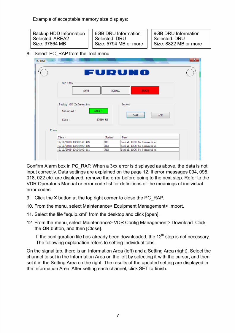
8102019 Ome44376d Vr3000 Mainte Cof26amp3bmol
httpslidepdfcomreaderfullome44376d-vr3000-mainte-cof26amp3bmol 957
7
Example of acceptable memory size displays
Backup HDD InformationSelected AREA2Size 37864 MB
6GB DRU InformationSelected DRUSize 5794 MB or more
9GB DRU InformationSelected DRUSize 8822 MB or more
8 Select PC_RAP from the Tool menu
Confirm Alarm box in PC_RAP When a 3xx error is displayed as above the data is not
input correctly Data settings are explained on the page 12 If error messages 094 098
018 022 etc are displayed remove the error before going to the next step Refer to the
VDR Operatorrsquos Manual or error code list for definitions of the meanings of individual
error codes
9 Click the X button at the top right corner to close the PC_RAP
10 From the menu select Maintenancegt Equipment Managementgt Import
11 Select the file ldquoequipxmlrdquo from the desktop and click [open]
12 From the menu select Maintenancegt VDR Config Managementgt Download Click
the OK button and then [Close]
If the configuration file has already been downloaded the 12th step is not necessary
The following explanation refers to setting individual tabs
On the signal tab there is an Information Area (left) and a Setting Area (right) Select the
channel to set in the Information Area on the left by selecting it with the cursor and then
set it in the Setting Area on the right The results of the updated setting are displayed in
the Information Area After setting each channel click SET to finish
8102019 Ome44376d Vr3000 Mainte Cof26amp3bmol
httpslidepdfcomreaderfullome44376d-vr3000-mainte-cof26amp3bmol 1057
8
22 RadarRadar Setup is performed in the Radar Tab
Equipment Setup
1 Click the Radar tab
The Radar information setup screen appears
2 Select a radar channel from the Information area For example click the CH No1 boxto open the corresponding setup
3 Click the Select Equipment button in the Setting Area The following dialogue boxappears
4 Select a radar model
For example as in the above illustration select Radargt RadarInterfacegtFurunogtFAR-28x7gt SXGA(60Hz) and click the OK button As in thefollowing illustration FAR-28x7 appears in the Type No field in the CH No 1 of theInformation Area Detailed information about the selected radar appears in the Setting Area
8102019 Ome44376d Vr3000 Mainte Cof26amp3bmol
httpslidepdfcomreaderfullome44376d-vr3000-mainte-cof26amp3bmol 1157
9
If your radar model is not in the list enter the required information manually Thesetting values are the same as the previous Web Configuration values
5 Click the Image Capture button in the Setting Area Confirm the correct video signal6 If required update the Setting Area item contents
It is not necessary to enter information very every item in the Setting Area For easyidentification of Input Source enter Equipment Category Brand Type No and DataName
7 Click the Set button to finish
8 To setup multiple radars repeat steps 2 through 7
9 Click the Check button in the setting area to perform radar check Results appear inthe Check section of the Information Area
8102019 Ome44376d Vr3000 Mainte Cof26amp3bmol
httpslidepdfcomreaderfullome44376d-vr3000-mainte-cof26amp3bmol 1257
10
To import the exact settings to another ship save the settings of the device in the Setting Area to the PC database
1 Click on Reflect Equipment
2 Copy the file to the PC by using Maintenancegt Equipment Managementgt Export inthe menu
3 Import to the other shiprsquos VDR from the PC
How to Set the Record Pattern
When there are two or more Radar units connected to the VDR select which radar torecord to
Note When using a 6 GB DRU it possible to record to 1 channel and when using a 9 GBDRU it is possible to record to 2 channels
1 In the Setting Area click the Recording Mode button The following dialogue boxappears
R1-R4 1st Radar (CH No1)~4
th Radar (CH No4)
G Records signal to the youngest radar number in a group pattern (ex R1-R4 aregrouped) If the youngest number is inactive signal is recorded to the next youngestnumber in sequence within the group
I Indicated unit recordssends
N Indicated unit does not recordsend
2 Select a recording pattern from Patterns 1-4
For example the settings in the above illustration are as follows
Recording Pattern 1 R1 signal is recorded to DRU R2 ndash R4 do not record
R1 and R2 signals are recorded to the Backup HDD R3ndashR4 donot record
Network Sending R1-R4 all send to network
Recording Pattern 3 Recording signal to the DRU automatically routes to the nextyoungest active number in the group between R1 and R3 R4 Does not recordExample If R1 is inactive signal is recorded to R2
Recording to Backup HDD Same as DRU
Send to Network R1-R4 all is sent to the network
3 Update I and N as needed
8102019 Ome44376d Vr3000 Mainte Cof26amp3bmol
httpslidepdfcomreaderfullome44376d-vr3000-mainte-cof26amp3bmol 1357
11
Place the cursor above either I or N and left click to alternate With this I is set torecord while N is set to not record G cannot be changed
4 After completing setup click the OK button
5 To record settings to the database click Reflect Equipment in the Setting Area
How to Enter Information Manually
This VDR system receives in VESA (Video Electronics Standards Association) signal Image signal 05-1Vpp (When using composite signal the minimum synchronization
signal is 50 mV)
Horizontal Synchronization Signal Max plusmn91146 kHz
Vertical Synchronization Signal Max 35 Hz
Acceptable Image Resolution 640x480 ndash 1280x1024
Channel number conforms to the number displayed by the DCU
To set the Radar tab do the following
1 Click the Radar tab
2 Choose the channel with the entered Radar Image from the Information Area
3 Check the Active box in the Setting Area and enter the Horizontal and Verticalresolution of the incoming image in the Horizontal resolution and Vertical resolutioncolumns
4 Click the Set button
5 Click the Image Capturehellip button The Image Capture dialogue box appears
6 Click the Test button in the Image Capture window Radar image appears a fewseconds later
7 If the image is normal close the Image Capture window8 Input each item in the Setting Area
8102019 Ome44376d Vr3000 Mainte Cof26amp3bmol
httpslidepdfcomreaderfullome44376d-vr3000-mainte-cof26amp3bmol 1457
12
Items are as follows
Active Check a channel to activate it
Brand Enter brand nameType No Enter type noCheck Set and activate checkData Name Enter data nameHorizontal resolution Set horizontal resolutionVertical resolution Set vertical resolutionHorizontal Offset Move the picture horizontallyVertical offset Move the picture verticallyPLL This sets the frequency of the PLL-oscillatorCDEV Set CDEV
VCOSL Set VCO Signal LeadPhase (0-63) Phase setting selects the phase of the sampling clock relativeto phase locked loop signal in 64 steps of 5625 degrees IfPhase is not set correctly any section of an image consistingof vertical lines may show line ldquotearingrdquo
Sync Type Select the type of video sync signalHorizontal sync polarity Set the polarity of the horizontal sync signalVertical sync polarity Set the polarity of the vertical sync signalHDVD Sync Termination Sets horizontal and vertical synchronization point When
using a composite signal set to 75ohmsPulse Width for VD Detection (0-1020 Step4) Sets the pulse width for video signal
detectionInterlace Type When the video image is interlace set ldquoInterlaceldquo sampling
mode In Interlace mode the even pixels are sampled on oneframe and odd pixels are sampled on the other frame
8102019 Ome44376d Vr3000 Mainte Cof26amp3bmol
httpslidepdfcomreaderfullome44376d-vr3000-mainte-cof26amp3bmol 1557
13
Interlace Polarity Set interlace polarityITRP (0-4092 Step4) Enter interlace pulse positionITRW (0-4092 step4) Enter interlace pulse widthSampling Rate Display sampling rate Fixed at ldquo15 secondsrdquoCompress Type (viewer) Set compress type (viewer)Color Bit Display and set Color BitChange Pump Current Set pump current Fixed at ldquo05 mArdquo
Video Clock Polarity Set video clock polarity Fixed at ldquoThroughrdquoCounter Clock SelectionSelect counter clock selection Fixed at ldquo49 MHzrdquoVCO Clock Hold Sets VCO clock holdRed Gain (0-255) Enter red gainGreen Gain (0-255) Enter green gainBlue Gain (0-255) Enter blue gainRed Offset (0-255) Enter red offsetGreen Offset (0-255) Enter green offsetBlue Offset (0-255) Enter blue offsetBlack Level (0-255) Enter black levelEquipment Category Enter equipment category
Board Name Enter board name for corresponding channelNote Enter note
Note Offset Phase and Color Bit change with the length of the antenna cable
Marked Items For easy identification of input source enter Equipment Category Brand
Type No and Data Name
Measurement BoxThe Measurement Box is located on the left side of the Information Area The LOWHorizontal and Vertical counter should be higher than the HIGH counter If reversely the
HIGH counter is higher than the LOW counter it is possible that the SYNC Polaritysettings are adjusted incorrectly
8102019 Ome44376d Vr3000 Mainte Cof26amp3bmol
httpslidepdfcomreaderfullome44376d-vr3000-mainte-cof26amp3bmol 1657
14
Config Management
After all items have been set up proceed to the final setting management This can only
be executed one time after all tabs have been set up
1 Click on VDR Config Management in the Maintenance menu
2 Click on the Upload button to send all sent data to the VDR memory
3 Click each individual Write button to record to DRU Backup HDD and CF Note
If the settings are not uploaded to the VDR they have no effect on the unit
4 Click the Close button to close the VDR Config Management Dialogue Box
8102019 Ome44376d Vr3000 Mainte Cof26amp3bmol
httpslidepdfcomreaderfullome44376d-vr3000-mainte-cof26amp3bmol 1757
15
23 Serial Signal
The Serial tab sets the RS-422 signals received at the terminal board (SI01-SI08) and the
junction box (SI09-SI72) This channel is not only for NMEA but also binary and ASCII
data
Set the Serial tab as follows1 Click the Serial tab
2 Select a channel from the Information window
3 Click the Select Equipment button in the Setting Area
4 Choose the unit that is connected to the indicated Channel and click the OK Button
5 Adjust items as needed in the Setting Area
8102019 Ome44376d Vr3000 Mainte Cof26amp3bmol
httpslidepdfcomreaderfullome44376d-vr3000-mainte-cof26amp3bmol 1857
16
6 After finishing the settings for one channel click the Set buttonNote Be sure to do this before moving another channel
7 Repeat steps 2-6 to set up each channel
When running Config Management for Tab Settings
1 From the Maintenance menu click VDR Config Management and then Config
2 Click the Upload button to record data to the VDR memory3 Click the Write button to save data to the DRU backup HDD and CF
The buttons in the Setting Area are as followsSet Save edited dataCapture Received data shown in the serial window dialog boxSelect Equipment Select equipment settings (saved to the database) to reflect in
a channelReflect Equipment Save the equipment setting data to the databaseCheck Check all channels OK or NG (No Good) shown in
Information window
Individual Item ExplanationActive Put check in check box to make channel activeBrand Enter brand nameType No (Equipment Name) Set type no (equipment name)Check Do equipment checkData Name Enter data nameData Type Enter data typeBaud Rate Set baud rate (Available for SI01 to SI08)Data Bit Set number of bits (Available for SI01 to SI08)Parity Bit Set parity bit (Available for SI01 to SI08)Stop Bit Set stop bit (Available for SI01 to SI08)Source Checksum Enter checksum for GPS sourceTime out Set time outEquipment Category Set equipment categoryBoard Name Enter board names where channels are presentNote Enter note
Marked Items For easy identification of input source enter Equipment Category Brand
Type No Date and Name
8102019 Ome44376d Vr3000 Mainte Cof26amp3bmol
httpslidepdfcomreaderfullome44376d-vr3000-mainte-cof26amp3bmol 1957
17
24 Analog SignalAnalog signal is input via Junction Box IF-8530 (optional for VR-3000S)Receivable signal ndash10 to +10 V or 4 to 20mA
Connect the analog signal to V and G terminals on the Junction Box When 4 to 20 mAsignal is connected make a short circuit between the V and I input terminals with jumper
wireThe basic procedure for setting up the analog signal is as follows
1 Click the Analog tab
2 Select channel from the Information Area
3 Set detailed information of the selected channel in the Setting Area Refer to thefollowing illustration to enter detailed item information
In the factory settings there is no preset data when the Select Equipment button is
pressed In the case that the setup was completed on another ship and saved usingReflect Equipment import the data by clicking Select Equipment and choosing thesaved data
4 In the following order calibrate the Analog signal
① Click the Calibration button in the Setting Area
② Enter the voltage (or current) value for Calibration Point 1 and thecorresponding engineering value in the left and right boxes
③ Enter values for Calibration Point 2④ Enter unit for the values in Engineering Value Unit
8102019 Ome44376d Vr3000 Mainte Cof26amp3bmol
httpslidepdfcomreaderfullome44376d-vr3000-mainte-cof26amp3bmol 2057
18
In the above image the Engineering Value Unit is set to degrees (deg) TheCalibration Point 1 is -10V corresponding to 0 degrees Calibration Point 2 is10V corresponding to 30 degrees This is set corresponding to the connectedanalog sensor
When the Apply button is clicked the New Engineering Value of 29835Vcorresponding to the input Voltage of 989V is displayed in the bottom fieldWhenever the input value is changed this value also changes Check that theNew Engineering Value is within an appropriate range
Another method is to observe the Voltage (or Current) field in the top field andpress the Hold button of Point 1 when an appropriate value is displaying Dothis again for Point 2
⑤ Click the OK Button
5 When setting is complete click the Set button Be sure to do this before movinganother to channel
6 Repeat steps 1-5 to set up all channels
When using Config Manager with Tabs
1 From the Maintenance menu click VDR Config Management and then Config
2 Click the Upload button to record to VDR memory
3 Click the Write buttons to record to DRU Backup HDD and CF memory
The items in the Setting Area are as shown below Active Put check in check box to make channel activeBrand Enter brand name
Type No Set type no (equipment name)
Check Do equipment checkData Name Enter data nameData Type Analog Data type (0~10V -10~10v 4~20mV)
Sampling Rate Display sampling rateCalibration Active Disable and enable analog calibrationCalibration Point 1 Enter calibration point 1
Calibration Point 1 Value Enter calibration point 1 valueCalibration Point 2 Enter calibration point 2Calibration Point 2 Value Enter calibration point 2 valueEngineering Value Unit Enter engineering value unit
8102019 Ome44376d Vr3000 Mainte Cof26amp3bmol
httpslidepdfcomreaderfullome44376d-vr3000-mainte-cof26amp3bmol 2157
19
Note For -marked boxes values that are set at the Analog Calibration dialog box aredisplayed
Equipment Category Set equipment categoryBoard Name Enter board names where channels are presentNote Enter note
Marked Items For easy identification of input source enter Equipment CategoryBrand Type No Data and Name
25 Digital Signal
Digital signal is connected via Junction Box IF-8530 (optional for VR-3000S) The
receivable signal is 10-32 V for voltage signal or contact signal For voltage signal
connect to A and B input terminals on the Junction Box For contact signal connect to B
and G input terminals on the Junction Box Also make a short-circuit between the 24 and
A input terminals with a jumper wire
To set up the Digital tab
1 Click the Digital tab
2 Select a channel from the Information Area
3 Set up the digital signal from the Setting Area Refer to the following individual item
explanation
In the factory settings there is no preset data when the Select Equipment button is
pressed In the case that the setup was completed on another ship and saved using
Reflect Equipment import the data by clicking Select Equipment and choosing the
saved data
4 When setting Digital Signal to each 64 channel group perform the following
directions1 Click the Calibration button in the setting area
8102019 Ome44376d Vr3000 Mainte Cof26amp3bmol
httpslidepdfcomreaderfullome44376d-vr3000-mainte-cof26amp3bmol 2257
20
2 Check the active column of the channel group being set
3 Enter the status in columns 0 and 1 of that group
4 Click the OK Button
5 When finished setting up click the Set button
6 Repeat steps 2-5 to set up other channels
When using Config Manager with Tabs
1 From the Maintenance menu click VDR Config Management
2 Click the Upload button to record to VDR memory
3 Click the Write buttons to record to DRU Backup HDD and CF memory
The items in the Setting Area are as shown below
Active Put check in check box to make channel activeBrand Enter brand name
Type No Set type no (equipment name)Check Do equipment checkData Name Enter and display data nameContact Type Set contact type NO normal open NC normal closeSampling Rate Display sampling rateCalibration Active Disable and enable digital calibrationActive Status (1) Set status display when (1) is activeActive Status (0) Set status display when (0) is activeEquipment Category Set equipment categoryBoard Name Enter board names where channels are presentNote Enter note
Marked Items For easy identification of input source enter Equipment CategoryBrand Type No Date and Name
8102019 Ome44376d Vr3000 Mainte Cof26amp3bmol
httpslidepdfcomreaderfullome44376d-vr3000-mainte-cof26amp3bmol 2357
21
26 Audio
Microphone and VHF audio settings are performed in the Audio tab
Set the items in the Audio tab as shown below
1 Click the Audio tab
2 Select channel from the Information Area3 Click Select Equipment in the Setting Area
4 Click on the connected device in the indicated channel The setting contents aredisplayed in the Information and Setting Areas
5 If required update the item contents in the Setting Area Refer to the detailed itemexplanation below
6 After completing settings for a channel click the Set buttonNote Be sure to click the Set button before moving to another channel
7 Repeat steps 2-6 to set up other channels
8102019 Ome44376d Vr3000 Mainte Cof26amp3bmol
httpslidepdfcomreaderfullome44376d-vr3000-mainte-cof26amp3bmol 2457
22
When using Config Manager with tabs
1 From the Maintenance menu click VDR Config Management
2 Click the Upload button to record to VDR memory
3 Click the Write buttons to record to DRU Backup HDD and CF memory
MIC testDo the MIC test to check whether audio is received clearly in adequate level or not
1 Click the MIC TEST button in the Setting Area
2 Click the TEST button in the MIC Test dialogue box MIC test results are displayed in
the MIC Test dialogue box
3 Click the Close button to close the dialogue box
Note Not the same recordingplayback function as the previous Web Configuratorsoftware
Continuous MIC TestRun the continuous MIC test as needed accordingly
1 Click the Continuous MIC Test button in the Setting Area2 Set up how many times to perform in the Continuous MIC Test dialogue box and click
the Test button
3 Click the Close button to close the dialogue box
8102019 Ome44376d Vr3000 Mainte Cof26amp3bmol
httpslidepdfcomreaderfullome44376d-vr3000-mainte-cof26amp3bmol 2557
23
Active Put check in check box to make channel activeBrand Enter and display brand nameType No Set type no (equipment name)Check Do equipment checkData Name Enter data nameInput Type Enter input type Sampling Data Bit Displays sampling data bit rate
Sampling Frequency Displays Sampling FrequencyCodec Sets MIC typeMIC Test Active M1M3M5 Put a checkmark when performing MIC Test of M1M3M5MIS Test Active M2M4M6 Put a checkmark when performing MIC Test of M2M4M6 MIC M1M3M5 Position Enter MIC position of MIC M1M3M5MIC M2M4M6 Position Enter MIC position of MIC M2M4M6Threshold Level M1M3M5 Enter MIC test threshold level of MIC M1M3M5Threshold Level M2M4M6 Enter MIC test threshold level of MIC M2M4M6Equipment Category Set equipment categoryBoard Name Enter board names where channels are present
Note Enter note Marked Items For easy identification of input source enter Equipment Category BrandType No Date and Name
8102019 Ome44376d Vr3000 Mainte Cof26amp3bmol
httpslidepdfcomreaderfullome44376d-vr3000-mainte-cof26amp3bmol 2657
24
27 Alarm
Alarm and Alarm Status settings are found in the Alarm tab
The Alarm tab shows the following information about alarms Click the Time Categoryand Name tabs in the title bar to sort
Time Time of alarm
Category Alarm categoryName Name of alarm
Number Alarm number
Status Alarm status
Alarm Search
1 Click the Search button above the Alarm tab The Search dialogue box appears
2 Add a checkmark to any desired search items (multiple items can be selected)
Start Time Display name of alarms generated after a certain time
End Time Display name of alarms generated before a certain time
Name Display information for alarm name entered
8102019 Ome44376d Vr3000 Mainte Cof26amp3bmol
httpslidepdfcomreaderfullome44376d-vr3000-mainte-cof26amp3bmol 2757
25
Number Display information for alarm number entered
Status Display alarm status for alarm name entered
3 In the checked items column input the desired search items
4 Click the Search Button
Close the Search box to cancel a search
Note During a search the upper left Mode changes from Play to Search andDisplay search related information
8102019 Ome44376d Vr3000 Mainte Cof26amp3bmol
httpslidepdfcomreaderfullome44376d-vr3000-mainte-cof26amp3bmol 2857
26
28 Event
Click the items shown below to sort by item selected
Note You can sort the items in ascending order () descending order () and
initialization order (no symbol)
Time Time an event occurred
Category Category of an event
Name Name of an event
Contents1 Display data associated with log
Contents2 Display data associated with log
Event Search
Do the following to search events
1 Click the Search button on the upper right of the Event tab
2 In the dialogue box add a checkmark to desired search items Multiple items can bechecked
Start Time Display name of event generated after a certain time
End Time Display name of event generated before a certain time
Name Display event names entered
Number Display event numbers entered
Status Display event status entered
Enter information about the checked event to search in the character input box
3 Click the Search button
Note The mode changes from Play to Search when performing a search
8102019 Ome44376d Vr3000 Mainte Cof26amp3bmol
httpslidepdfcomreaderfullome44376d-vr3000-mainte-cof26amp3bmol 2957
27
29 Hardware
The Hardware tab provides information about the system hardware
The buttons in the Setting window work as follows
Self Check Status Display status of self check
CPU Display information about the CPU
Memory Size Display memory size
CPU Board Display status of CPU board
Audio Board Display status of Audio board
Serial Board Display status of Serial board
Radar Interface Board Display status of Radar Interface boardNote Enter and display note
Marked items are optional
8102019 Ome44376d Vr3000 Mainte Cof26amp3bmol
httpslidepdfcomreaderfullome44376d-vr3000-mainte-cof26amp3bmol 3057
28
210 JB
Connect the Junction Box to the DCU before turning on the system
The JB tab functions to set up the Junction Box
The basic procedure for setting up the Junction Box is as follows
1 Click the JB tab2 Select a Junction Box from the Information Area
3 Set up the Junction Box from the Setting Area
4 Click the Set button (Be sure to do this before moving to another channel)5 Click the Check button to perform an inspection on all channels In the Information
Area check column either OK or NG (No Good) is displayed
When using Config Manager with Tabs
1 From the Maintenance menu click VDR Config Management
2 Click the Upload button to record to VDR memory
3 Click the Write buttons to record to DRU Backup HDD and CF
The items in the Setting window work as followsActive Put check in check box to make channel activeNo Display Junction Box numberIP Address Display IP address of Junction Box acquired by VDRMAC Address Display MAC address of Junction Box acquired by VDRCheck Enable and disable equipment checkNote Enter note
Marked items are optional
8102019 Ome44376d Vr3000 Mainte Cof26amp3bmol
httpslidepdfcomreaderfullome44376d-vr3000-mainte-cof26amp3bmol 3157
29
211 Life Time
The Life Time tab controls consumable parts
The basic procedure for using the Life Time tab is as follows
1 Click the Life Time tab
2 Select a Type No in the Information Area3 Set up the chosen part from Setting Area
4 Click the Set button
Note Be sure to click the Set button before moving to set up a different Type
The items in the Setting window work as follows
Type No Enter and display type no
Data Name Enter and display data name
Level Set replacement level Legal Exchange Parts or Normal Exchange Parts
Replace Date Enter and display recommended day of replacement
Lifetime Term Not usedNote Enter and display note
The Status column of the Information Area displays as follows
OK The recommended date of replacement shown in the Replace Date
box in the Information window has not passed
Out of Date The date of replacement has passed
None The date of replacement has not been set
8102019 Ome44376d Vr3000 Mainte Cof26amp3bmol
httpslidepdfcomreaderfullome44376d-vr3000-mainte-cof26amp3bmol 3257
30
212 Network
The Network tab sets the system network
The basic procedure for setting up the system network is as follows
1 Click the Network tab
2 Select a port from the Information Area
3 Set up the network from the Setting Area
4 Click the Set button
Note1 Be sure to click the Set button before moving to set up a different Port
Note2 After setting the system network reboot the VDR to apply the settings
The items in the Setting window work as follows
LAN Type Enter LAN type Public LAN or JB LAN
MAC Address Enter MAC address
IP Address Enter IP address
Subnet Mask Enter subnet mask
Gateway Address Enter gateway address
Live Play Multicast Mode (Only JB LAN) Check box to enable live player multicast
mode
Multicast Address (Only Public LAN) Enter and display live player multicast addressNote Enter note
Marked items are optional
8102019 Ome44376d Vr3000 Mainte Cof26amp3bmol
httpslidepdfcomreaderfullome44376d-vr3000-mainte-cof26amp3bmol 3357
31
213 System
The System tab sets system related functions
The basic procedure for using the System tab is as follows
1 Click the System tab
2 Set up the chosen item from the Setting Area
3 Click the Set button
Note Be sure to click the Set button before moving to a different tab
The items in the Setting window work as follows
VDR Type Enter type of VDR
VDR Model Enter model number of VDR
Radar Interface Check Enable and disable checking of the Radar Interface board
Junction Box Count Enter number of junction boxes in system
DRU Flash Count Enter number of DRU flash disks in system Set 1 when DRU
serial no is 5000 and more Set 3 when DRU serial no is less
than 5000
DRU Capacity Display capacity of DRU
Backup HDD Capacity Display capacity of Backup HDD
VDR Config Version Display version no of VDR
VDR Config Date Display the number of hours the VDR settings have
been saved
VDR Config Code Display configuration identity code
Installation Engineer Enter name of the equipment installer
Installation Company Enter name of installers company
8102019 Ome44376d Vr3000 Mainte Cof26amp3bmol
httpslidepdfcomreaderfullome44376d-vr3000-mainte-cof26amp3bmol 3457
32
Installation Date Enter the date of the installation
MIC Test Time Enter the date of the MIC test
Note Enter note Marked items are optional
USB memory logging Do not check Enable
IEEE1394 BUS Error Auto Restart function Not used
IEEE1394 Active Node Count Do not change the default value of 3 (However set to 5
for serial number 5000 or less of DRU)
IEEE1394 Recover Process Limit Count Do not change the default value of 10
DRU Error Auto Restart function Not used
REBOOT DELAY TIME (sec) Do not change the default value of 10
LIMIT REBOOT COUNT Do not change the default value of 10
Live Player Max Connection Count The max number of Live Player V4 that can be
connected simultaneously The default no is two
but a maximum of five can be set here After you
change this option reboot the VDR to apply the
setting Disconnect the cable connected with
Live Player V4 (PC) from the VDR and thenreconnect it
214 Software
The Software tab sets and display software-related operations
The basic procedure for using the Software tab is as follows
1 Click the Software tab
2 Set up the chosen Item from the Setting Area
3 Click the Set button
8102019 Ome44376d Vr3000 Mainte Cof26amp3bmol
httpslidepdfcomreaderfullome44376d-vr3000-mainte-cof26amp3bmol 3557
33
The items in the Setting window work as follows
VDR System Program Display the VDR system program no
Process Version Display the process version
Power Distribution Unit (PDU) Display the version no of the PDU
Operation System Display the version no of the OS
Audio Driver Display the version no of the audio driverRAP Version Enter the version no of the RAP
AP Version Enter the version no of the AP
JB1-8 Boot Program Display the no of the RJB Boot program for Junction Boxes
1 to 8
JB1-8 App Program Display the no of the RJB App program for Junction Boxes
1 to 8
Watch Dog Interval Do not change the default value of 60 (Enter the process
response time A process is repeated if there is no response
within the time interval set here)
Giveup Interval Do not change the default value of 300 (Enter the restart
watch time The restarting of a process is stopped when the
number of times it has been restarted is exceeded within the
interval set here)
Refork Limit Do not change the default value of 10 (Enter the upper limit
for process restart The restarting of a process is stopped
when the number of times it has been restarted exceeds the
Give up Interval)
Note Enter note
Marked Items are optional
8102019 Ome44376d Vr3000 Mainte Cof26amp3bmol
httpslidepdfcomreaderfullome44376d-vr3000-mainte-cof26amp3bmol 3657
34
215 GPS
The GPS tab sets GPS-related parameters
The basic procedure for using the GPS tab is as follows
1 Click the GPS tab
2 Set up the chosen channel from the Information window3 Set up the chosen item in the Setting Area
4 Click the Set button
5 Repeat steps 2-4 to set up each Channel
6 Click the Check button to perform an inspection on all channels In the Information Area check column either OK or NG (No Good) is displayed
The items in the Setting window work as follows
Priority Display priority order
Date and Time SourceShip Position Source Set GPS source channel (serial channel
number for ZDA sentence)
Check Enable and disable checking
GPS Antenna Position From Bow Enter position of GPS antenna from bow
GPS Antenna Position From Stern Enter position of GPS antenna from stern
GPS Antenna Position From Port Enter position of GPS antenna from port
GPS Antenna Position From Starboard Enter position of GPS antenna from starboard
GPS Failure Threshold If the ZDA is input within the set time limit
the system restarts synchronized If not
input within the time limit the system restarts
without synchronization
8102019 Ome44376d Vr3000 Mainte Cof26amp3bmol
httpslidepdfcomreaderfullome44376d-vr3000-mainte-cof26amp3bmol 3757
35
GPS Delay Time by Time Sync Enter minimum time delay for time
synchronization Time synchronization is started
only in the time set here
GPS Difference Interval The time set here is added to the GPS time to
synchronize the system time Leave at the default
0 value setting
GPS Sync Giveup Time If the system receives the GPS time within the
time set the system synchronizes with the time
When not receiving a signal the system displays
an ldquoerror 26rdquo message
ZDA Timeout Enter value (seconds) for ZDA timeout (234 error)
from GPS
Note Enter and display note
Marked Items are optional
216 VesselThe Vessel tab sets and displays own ships information such as name and IMO number
The basic procedure for using the Vessel tab is as follows
1 Click the Vessel tab
2 Set up information in the Setting window
3 Click the Set button (Be sure to do this before moving to another port)
4 From the Maintenance menu click VDR Config Management and then Config5 Click the Write buttons to save data to the DRU backup HDD CF
The buttons in the Setting window works as follows
Vessel Name Enter name of vessel
Vessel IMO Number Enter IMO number of vessel
Vessel Flag Enter flag of vessel
Approval of Authority Enter name of approving authority
Note Enter note
Marked items are optional
8102019 Ome44376d Vr3000 Mainte Cof26amp3bmol
httpslidepdfcomreaderfullome44376d-vr3000-mainte-cof26amp3bmol 3857
36
217 Delivery
The Delivery tab functions to transmit data from the VDR to a PC via Ethernet LAN Do
not use this function during live connection
The basic procedure for using the Delivery tab is as follows
1 Click the Delivery tab
2 Click the Add button to show the Delivery Config window
3 Select protocol from the Protocol drop-down box (Unicast or Multicast)
4 Enter IP address in the IP address input box
5 Enter port number in the port number input box
6 Click the tab of the data to send (Analog Digital or Serial)
7 Select the channel of the data to send
8 If Serial was selected at step 6 select applicable data sentence from the Inactivewindow Click the right arrow to move the data sentence to the Active window
9 Click the OK button to close the Delivery Config window
10 The settings are listed in a table in the Delivery window Check the checkbox in the
Active column and then click the Set button
The buttons in the Setting window works as follows
Set Save edited settings
Add Create new delivery settings
Modify Modify selected delivery settings
Delete Delete selected delivery settings
8102019 Ome44376d Vr3000 Mainte Cof26amp3bmol
httpslidepdfcomreaderfullome44376d-vr3000-mainte-cof26amp3bmol 3957
37
3 How to Back up Configuration DataThis chapter shows how to back up configuration data to various storage media
Configuration data can be opened with Word Pad or any text editor other than Notepad
31 How to Back up Configuration Data to the Startup CompactFlash (CF)
Back up data to the startup CF after setting the VDR Configuration data is created on the
CF as a configini file
Note When the error shown below occurs during the downloading or uploading of
configuration data check the connection of the DRU Backup HDD and CF and then
upload or download the configuration data again
[CONN] Download failed
[CONN] Could not upload config file
If error occurs again re-install the VDR Maintenance Viewer
Do the following to back up data to a CF
1 Set up parameters on the tabs referring to Chapter 2
2 Click the Maintenance menu
3 Select VDR Config Management
4 Click the Upload button
5 A confirmation box appears click the OK button to start uploading to the VDR
6 Click the Write button where the arrow connects between VDR and DRU BackupHDD
7 A confirmation window appears click the OK button to save the configuration data tothe DRU and Backup HDD
8102019 Ome44376d Vr3000 Mainte Cof26amp3bmol
httpslidepdfcomreaderfullome44376d-vr3000-mainte-cof26amp3bmol 4057
38
8 Click the Write button where the arrow connects between the VDR and CF
9 A confirmation window appears click the OK button to save the configuration data tothe startup CF
10 Check that the PC VDR DRU Backup HDD and CF share the same VDR configcode
32 How to Back up Configuration Data to a PC
Configuration data saved to the PC can be edited with Wordpad and shared with other
vessels For future service ease it is recommended to backup configuration data to the
PC and have the data on board the vessel Also it is recommended to upload this data to
Furuno SMS (Service Management System) If unable to upload to Furuno SMS please
contact the Service Center Furuno Japan
To back up configuration data to the PC do as follows
1 Set up parameters on the tabs referring to Chapter 2
2 Click the Maintenance menu
3 Select VDR Config Management
4 Click the Export to button
5 A confirmation window appears click the OK button
6 Select where to save the data enter file name then click the Open button
7 Confirm that back up file is in the location selected
33 How to restore the default settings
Click the Default button on the VDR Config Management window to restore the default
settings of the DRU Backup HDD CF and VDR Maintenance Viewer
8102019 Ome44376d Vr3000 Mainte Cof26amp3bmol
httpslidepdfcomreaderfullome44376d-vr3000-mainte-cof26amp3bmol 4157
39
4 How to Upload Configuration Datafrom a PCThe procedure below shows how to upload configuration from the PC to aVR-3000VR-3000S
1 Click the Maintenance menu
2 Select VDR Config Management
3 Click the Import from button
4 The Open window appears Select configuration data and then click the Open button
5 Click the Upload button to upload data to the VR-3000VR-3000S
6 Click the Write buttons to save data to the DRU backup HDD and CF
8102019 Ome44376d Vr3000 Mainte Cof26amp3bmol
httpslidepdfcomreaderfullome44376d-vr3000-mainte-cof26amp3bmol 4257
40
5 Media ManagementThe media management feature deletes data from recording media initialization the
system etc There are two method LAN connection and Direct connection The Direct
connection takes longer time than the LAN connection Basically use the LAN connection
method
Note Initialization or creation of recording media is not available when Source Select onthe Live Player V4 is selected to Backup HDD
51 Initialization
This section shows how to delete data from the recording media Configuration data is
not deleted After performing the software configuration delete the data from the DRU
and HDD
Do the following to delete data from the DRU (LAN connection)
1 Set the PlaybackCPU switch in the DCU to the CPU position
2 Use an Ethernet cross cable to connect the PC to J14 (DATA) in the DCU (See page5)
3 Open the Tool menu
4 Select Media Management to open the VDR Media Management window
5 Check that IP address shown in the ldquoLAN Connect to IPrdquo in VDR Media Table Area isthe same as the IP address access point
6 Select ldquoLAN Connect to IPrdquo in the VDR Media Table column
8102019 Ome44376d Vr3000 Mainte Cof26amp3bmol
httpslidepdfcomreaderfullome44376d-vr3000-mainte-cof26amp3bmol 4357
41
7 Click the Analyze button A list of recording media connected to the VDR appears
Put a checkmark in the checkbox of the Select column for the DRU in the Name columnNote If there are several flash memories in the DRU all flash memories are shownCheck all flash memories shown
8 Select ldquoDRU Initializerdquo from the Operation dropdown list in the Operation area
10 Click the Run button
Do the following to delete data from the DRU (Direct connection)
1 Start Live Player V4 software
2 Open the Tool menu and select Source Select Select Live from the pull-downmenu
3 Click the Alarm tab and open Alarm History
4 Set the PlaybackCPU switch in the DCU to the Playback position
5 Wait approx 10 minutes and confirm that Alarm 174 occurs on Alarm History of LivePlayer V4
6 Connect an IEEEE1394 cable between J6 in the DCU and the PC
7 Open the Tool menu
8 Select Media Management to show the VDR Media Management window
9 Select Direct in the VDR Media Table column
10 Click the Analyze button A list of recording media connected to the VDR appears
11 Put a checkmark in the checkbox of the Select column for the DRU in the Namecolumn
Note If there are several flash memories in the DRU all flash memories are shownCheck all flash memories shown
12 Select ldquoDRU Initializerdquo from the Operation dropdown list in the Operation area
13 Enter password in the password column
14 Click the RUN button
8102019 Ome44376d Vr3000 Mainte Cof26amp3bmol
httpslidepdfcomreaderfullome44376d-vr3000-mainte-cof26amp3bmol 4457
42
Delete data from the Backup HDD as follows (LAN connection)
1 Set the PlaybackCPU switch in the DCU to the CPU position
2 Check that an Ethernet cross cable is connected between J14 in the DCU and the PC
3 Open the Tool menu
4 Select Media Management to open the VDR Media Management window
5 Check that IP address shown in the LAN Connect to IP in VDR Media Table Area is
the same as the IP address access point6 Select LAN Connect to IP in the VDR Media Table column
7 Click the Analyze button
8 A list of recording media connected to the VDR appears
9 Put a checkmark in the box of the Select column for the Backup HDD in the Namecolumn Select ldquoBackup HDD Initializerdquo from the Operation dropdown list in theOperation area
10 Click the Run button
Delete data from the Backup HDD as follows (Direct connection)
1 Start Live Player V4 software
2 Open the Tool menu and select Source Select Select Live from the pull-downmenu
3 Click the Alarm tab and open Alarm History
4 Set the PlaybackCPU switch in the DCU to the Playback position
5 Wait approx 10 minutes and confirm that Alarm 174 occurs on Alarm History of LivePlayer V4
6 Connect an IEEE1394 cable between J6 in the DCU and the PC
7 Open the Tool menu
8 Select Media Management to open the VDR Media Management window9 Select Direct in the VDR Media Table window
10 Click the Analyze button A list of recording media connected to the VDR appears
11 Put a checkmark in the check box of the Select column for the Backup HDD in theName column Select ldquoBackup HDD Initializerdquo from the Operation dropdown list in theOperation area
12 Enter password
13 Click the Run button
8102019 Ome44376d Vr3000 Mainte Cof26amp3bmol
httpslidepdfcomreaderfullome44376d-vr3000-mainte-cof26amp3bmol 4557
43
52 CreationThe Creation feature initializes recording media
Note1 This feature deletes ALL configuration data Backup all VDR configuration data
Note2 When you initialize medium that is a different format for the DRU or Backup HDDdelete all partitions with the disk management tool of Windows
Note3 When the Creation is failed try again If you can not initialize recording media tryunder condition as shown below
Do the Creation by the direct connection (When the Creation by the LAN
connection is failed)
Delete all partitions of the DRU or Backup HDD with the disk management tool of
Windows to do the Creation
If the Creation is still failed request service to repairreplace the DRU or Backup
HDD
Initialize the DRU as follows (LAN connection)
1 Set the PlaybackCPU switch in the DCU to the CPU position
2 Check that an Ethernet cross cable is connected between J14 in the DCU and the PC
3 Open the Tool menu
4 Select Media Management to open the VDR Media Management window
5 Check that IP address shown in the LAN Connect to IP in VDR Media Table Area isthe same as the IP address access point
6 Check ldquoLAN Connect to IPrdquo in the VDR Media Table column
7 Click the Analyze button A list of recording media connected to the VDR appears
8 Put a checkmark in the box of the Select column for the DRU in the Name column
Select ldquoDRU Creationrdquo from the Operation dropdown list in the Operation area
9 Click the Run button
Initialize the Backup HDD as follows (LAN connection)
1 To format the Backup HDD place a checkmark in the Select column of the listedrecord media in the Name column of the VDR Media Management dialogue box
2 From the Operation drop down list of the Operation area select ldquoBackup HDDCreation (Radar) or ldquoBackup HDD Creationrdquo
Two partition tools are available for the Backup HDD in the Media Management as
below
Backup HDD creation
This tool is used when the number of the SXGA video signal connected to the BackupHDD is the same as the DRU The same partition is created on both DRU and HDD
(1) When two SXGA video signals are recorded onto the HDD while 9-GB DRU isconnected
(2) When an SXGA video signal is recorded onto the HDD while 6-GB DRU isconnected
Backup HDD creation (radar)
This tool is used when two SXGA video signals are recorded onto the HDD with 6-GB
DRU connected The HDD has an area (radar) to record the second radar signal inaddition to the same partition as the DRU This tool cannot be used when 9-GB DRUis connected
3 Press the Run Button
8102019 Ome44376d Vr3000 Mainte Cof26amp3bmol
httpslidepdfcomreaderfullome44376d-vr3000-mainte-cof26amp3bmol 4657
44
Initialize the DRU as follows (Direct connection)
1 Start Live Player V4 software
2 Open the Tool menu and select Source Select Select Live from the pull-downmenu
3 Click the Alarm tab and open Alarm History
4 Set the PlaybackCPU switch in the DCU to the Playback position
5 Wait approx 10 minutes and confirm that Alarm 174 occurs on Alarm History of LivePlayer V4
6 Connect an IEEE1394 cable between J6 in the DCU and the PC
7 Open the Tool menu
8 Select Media Management to open the VDR Media Management window
9 Select Direct in the VDR Media Table window
10 Click the Analyze button A list of recording media connected to the VDR appears
11 Put a checkmark in the box of the Select column for the DRU and the desiredrecording media in the Name column In the Operation dropdown list of the Operationarea select ldquoDRU Creationrdquo
12 Enter password in the password column
13 Click the Run button
Initialize the Backup HDD as follows (Direct Connection)
1 To format the Backup HDD place a checkmark in the Select column of the listedrecord media in the Name column of the VDR Media Management dialogue box
2 From the Operation column of the Operation area select ldquoBackup HDD Creation(Radar) or ldquoBackup HDD Creationrdquo
Backup HDD creation
This tool is used when the number of the SXGA video signal connected to the BackupHDD is the same as the DRU The same partition is created on both DRU and HDD
(1) When two SXGA video signals are recorded onto the HDD while 9-GB DRU is
connected
(2) When an SXGA video signal is recorded onto the HDD while 6-GB DRU is
connected
Backup HDD creation (radar)
This tool is used when two SXGA video signals are recorded onto the HDD with 6-GBDRU connected The HDD has an area (radar) to record the second radar signal inaddition to the same partition as the DRU This tool cannot be used when 9-GB DRUis connected
3 Enter the password in the Password column
4 Press the Run Button
8102019 Ome44376d Vr3000 Mainte Cof26amp3bmol
httpslidepdfcomreaderfullome44376d-vr3000-mainte-cof26amp3bmol 4757
45
53 How to Enable Recording Area on the Backup HDD
This function enables writing over a recording area To prevent falsification of data all
recording areas must be saved otherwise this function is disabled To use this function push
the SAVE button Save the data before doing this procedure
Note Software version 135 or higher can enable writing over a recording area even if
all recording areas are not saved
Recording enable (LAN connection)
1 Set the PlaybackCPU switch in the DCU to the CPU position
2 Check that an Ethernet cross cable is connected between J14 in the DCU and the PC
3 Open the Tool menu
4 Select Media Management to open the VDR Media Management window
5 Check that IP address shown in the ldquoLAN Connect to IPrdquo in VDR Media Table Area isthe same as the IP address access point
6 Select ldquoLAN Connect to IPrdquo in the VDR Media Table column7 Click the Analyze button A list of recording media connected to the VDR appears
8 Put a checkmark in the box of the Select column for the Backup HDD in the Namecolumn
9 Select ldquoBackup HDD Recording Area Enablerdquo from the Operation dropdown list in theOperation area
10 Click the Run button
Recording enable (Direct connection)
1 Start Live Player V4 software
2 Open the Tool menu and select Source Select Select Live from the pull-down menu3 Click the Alarm tab and open Alarm History
4 Set the PlaybackCPU switch in the DCU to the Playback position
5 Wait approx 10 minutes and confirm that Alarm 174 occurs on Alarm History of LivePlayer V4
6 Connect an IEEE1394 cable between J6 in the DCU and the PC
7 Open the Tool menu
8 Select Media Management to open the VDR Media Management window
9 Select Direct in the VDR Media Table window
10 Click the Analyze button A list of recording media connected to the VDR appears11 Put a checkmark in the box of the Select column for the Backup HDD in the Name
column
12 Select ldquoBackup HDD Recording Area Enablerdquo from the Operation dropdown list in theOperation area
13 Enter password
14 Click the Run button
8102019 Ome44376d Vr3000 Mainte Cof26amp3bmol
httpslidepdfcomreaderfullome44376d-vr3000-mainte-cof26amp3bmol 4857
46
6 Other Functions
61 Software Management
The software download feature downloads VDR system software to the PC
To download software
1 Click the Maintenance menu
2 From the Software Management menu click Software Download to show theSoftware Download window
3 Enter the IP address 1000100 in the IP address box in the Update Server area
4 Click the Download Software button
5 The confirmation window appears click the OK button
The Software Backup Execute window shows the results of the download
Software is downloaded to C Program Files VDR Viewer Viewer Backup The software file
name is vdrtar
To Update Software
VDR system program version 16x can update the software with the procedure shownbelow
Note Do not update the file downloaded in procedures above
1 Click the Maintenance menu
2 From the Software Management menu click Software Upload to show the SoftwareUpload area
3 Click the Select button to show the Open window
4 Select update file (vdrtar) and click the Open button
8102019 Ome44376d Vr3000 Mainte Cof26amp3bmol
httpslidepdfcomreaderfullome44376d-vr3000-mainte-cof26amp3bmol 4957
47
5 Check the displayed Software information is correct
6 Enter the IP address 1000100 in the IP address box in the Update Server area
7 Enter password
8 Click the Update button
After the updating is completed the VDR is automatically restarted
Note Click the Restore button on the Software Update window to restore previoussoftware version This feature is available after updating the software
62 Password Management
The password can be changed for a serviceman to access the equipment Contact
FURUNO to get the default password to use during installation
Serviceman password
1 Click the Maintenance menu2 Select Change Serviceman Password from Password Management to show the
Change Serviceman Password window
3 Enter current password in the Old Password box
4 Enter the new password in the New Password box of the Change Password area
5 Enter new password again in the Confirm New Password box
6 Click the OK button
Audio password
The audio password set at the VDR Maintenance Viewer can be removed to enable
audio access without password1 Click the Maintenance menu
2 Select Change Audio Password from Password Management to show the Change Audio Password window
3 The confirmation window appears click the OK button
8102019 Ome44376d Vr3000 Mainte Cof26amp3bmol
httpslidepdfcomreaderfullome44376d-vr3000-mainte-cof26amp3bmol 5057
48
63 Record ComparisonThe integrity of the DRU and Backup HDD recordings can be compared This function isused by the RampD engineer for debugging
Follow the procedure as shown below
1 Click the Maintenance menu2 Select Record Comparison to show the Record Comparison window
The results are shown every 15 seconds in the Record Comparison window
8102019 Ome44376d Vr3000 Mainte Cof26amp3bmol
httpslidepdfcomreaderfullome44376d-vr3000-mainte-cof26amp3bmol 5157
49
64 Software History
This section shows you to save and configure software history (communications record)
How to save software history
Note When the error dialog appears while saving the software history restart the VDR
Maintenance Viewer
1 Click the Maintenance menu
2 Select Software History Collect
3 Click the Select button The Open dialog box appears
4 Select where to save the data then click the Open button
5 Select desired save condition then click the OK buttonNone No savingAt Once Save the software history manually Saving begins as soon as the OK button is clickedPeriodic For debugging Do not use otherwise The intervals are 30 sec 60 secand 120 secAlarm Detection For debugging Do not use otherwise Software history is savedwhen specified alarm is released Enter alarm number
How to configure software communications record
The RampD engineer uses this function for debugging Do not do this procedure unless
required Malfunction can result
1 Click the Maintenance menu
2 Select Software History Config
3 Do the followingProcess Select the type of communications record to save ALL saves allcommunications records
Detail Hide or show detailed information4 Click the Send button
8102019 Ome44376d Vr3000 Mainte Cof26amp3bmol
httpslidepdfcomreaderfullome44376d-vr3000-mainte-cof26amp3bmol 5257
50
65 Easy SetupThis feature sets equipment settings in batch and creates a data file of those settings
Default template The default template is created with the settings entered at installation
1 Click the Maintenance menu
2 Select Easy Setup to show the Template Selection window
3 Select Default Template
4 Click the Start button to show the Easy Setup window
5 Right click the channels (Radar Audio Digital Serial Analog) then select Edit toshow the Equipment Selection window
6 From the Equipment Directory window select equipment connected to the selectedchannel and then click the OK button
7 Repeat steps 5 and 6 to select equipment settings for each channel
8 Click the Save button in the Easy Setup window to show the Save window
9 Select where to save the file and enter file name
10 Click the Save button
8102019 Ome44376d Vr3000 Mainte Cof26amp3bmol
httpslidepdfcomreaderfullome44376d-vr3000-mainte-cof26amp3bmol 5357
51
Specific template Use a file already created
1 Click the Maintenance menu
2 Select Easy Setup to show the Template Selection window
3 Check Specified Template
4 Click the Select button and then select the file to edit
5 Click the Start button to show the Easy Setup window
6 Right click the channels (Radar Audio Digital Serial Analog) then select Edit toshow the Equipment Selection window
7 From the Equipment Directory window select equipment connected to the selectedchannel and then click the OK button
8 Repeat steps 6 and 7 to select equipment settings for each channel
9 Click the Save button in the Easy Setup window to show the Save window
10Select where to save the file and enter file name
11 Click the Save button
66 Equipment Management
This feature controls the import and export of equipment settings
Import data file
Import data files of equipment settings created in Easy Setup etc to the VDR
1 Click the Maintenance menu
2 Select Import from Equipment Management to show the Open window
3 Select the data file to import and click Open
Export data file
Export data files of equipment settings from the VDR to a PC
1 Click the Maintenance menu
2 Select Export from Equipment Management to show the Save window
3 Enter file name
4 Click the Save button
8102019 Ome44376d Vr3000 Mainte Cof26amp3bmol
httpslidepdfcomreaderfullome44376d-vr3000-mainte-cof26amp3bmol 5457
52
67 PC_RAP
This feature enables the same operation of the RAP (Remote Alarm Panel) from a PC
Select PC_RAP from the Tool menu to show the PC_RAP window
The buttons in the PC_RAP window function as shown below
SAVE Stop recording in the area where recording is currently being done
ACK Silence audio alarm
The PC_RAP display shows the following information with LEDs
RAP_LEDs Display the status of LEDs on the RAPSave The Save button blinks yellow when pushed When the 4 memory
areas have data recorded to them the Save button lights orange when
pushed
Normal Lights (green) where there are no unconfirmed or not restored
alarms
Error Flashes (red) for not confirmed alarm Lights (red) for unrestored
alarm
8102019 Ome44376d Vr3000 Mainte Cof26amp3bmol
httpslidepdfcomreaderfullome44376d-vr3000-mainte-cof26amp3bmol 5557
53
Backup HDD Information Display status of backup HDD
Selected Display current recording area and its status in green for
normal operation and in red for abnormal operation
Size Display capacity of backup HDD
Alarm area displays unconfirmed alarms
Time Display time alarm was generatedNumber Display number of alarm
Name Display name of alarm
Pending Alarm displays the unrestored alarms out of confirmed alarms only
Time Display time alarm was generated
Number Display number of alarm
Name Display name of alarm
8102019 Ome44376d Vr3000 Mainte Cof26amp3bmol
httpslidepdfcomreaderfullome44376d-vr3000-mainte-cof26amp3bmol 5657
54
68 Other
Status Monitor
The status monitor feature provides comprehensive data about the status of the VDR
From the menu bar click Toolgt Status Monitor to show the Status Monitor window
The buttons in the Status Monitor window work as shown below
Reload Settings for automatic refreshing of the status monitor
ON Turn automatic refresh OFF
OFF The Status Monitor is refreshed every five seconds
Save Available when Reload ON is selected The contents of the Status Monitor can be
saved to a text fileUpdate Update the Status Monitor display
Close Close the Status Monitor display
8102019 Ome44376d Vr3000 Mainte Cof26amp3bmol
httpslidepdfcomreaderfullome44376d-vr3000-mainte-cof26amp3bmol 5757
VDR Error List
This feature compiles all the errors shown on the RAP for easy reference
Access from MenugtToolgtVDR Error List
The VDR error list contains the following information
NO Display the number of the error
Title Display the name of the error
Detail Display details about the error
Exchange Check
This feature removes the alarms generated when replacing the DRU or backup HDD
Access MenugtToolgtExchange Check select either DRU or Backup HDD and click OK
Reboot
Reboot the VDR
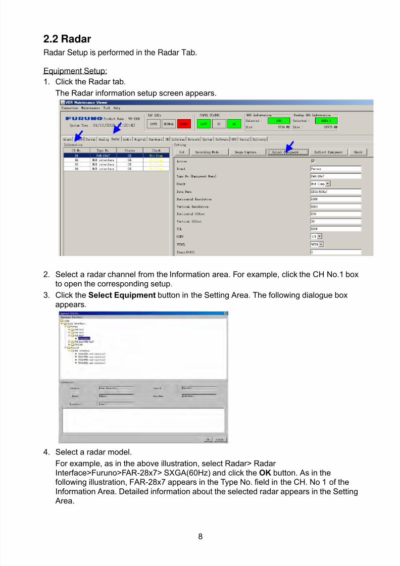
8102019 Ome44376d Vr3000 Mainte Cof26amp3bmol
httpslidepdfcomreaderfullome44376d-vr3000-mainte-cof26amp3bmol 1057
8
22 RadarRadar Setup is performed in the Radar Tab
Equipment Setup
1 Click the Radar tab
The Radar information setup screen appears
2 Select a radar channel from the Information area For example click the CH No1 boxto open the corresponding setup
3 Click the Select Equipment button in the Setting Area The following dialogue boxappears
4 Select a radar model
For example as in the above illustration select Radargt RadarInterfacegtFurunogtFAR-28x7gt SXGA(60Hz) and click the OK button As in thefollowing illustration FAR-28x7 appears in the Type No field in the CH No 1 of theInformation Area Detailed information about the selected radar appears in the Setting Area
8102019 Ome44376d Vr3000 Mainte Cof26amp3bmol
httpslidepdfcomreaderfullome44376d-vr3000-mainte-cof26amp3bmol 1157
9
If your radar model is not in the list enter the required information manually Thesetting values are the same as the previous Web Configuration values
5 Click the Image Capture button in the Setting Area Confirm the correct video signal6 If required update the Setting Area item contents
It is not necessary to enter information very every item in the Setting Area For easyidentification of Input Source enter Equipment Category Brand Type No and DataName
7 Click the Set button to finish
8 To setup multiple radars repeat steps 2 through 7
9 Click the Check button in the setting area to perform radar check Results appear inthe Check section of the Information Area
8102019 Ome44376d Vr3000 Mainte Cof26amp3bmol
httpslidepdfcomreaderfullome44376d-vr3000-mainte-cof26amp3bmol 1257
10
To import the exact settings to another ship save the settings of the device in the Setting Area to the PC database
1 Click on Reflect Equipment
2 Copy the file to the PC by using Maintenancegt Equipment Managementgt Export inthe menu
3 Import to the other shiprsquos VDR from the PC
How to Set the Record Pattern
When there are two or more Radar units connected to the VDR select which radar torecord to
Note When using a 6 GB DRU it possible to record to 1 channel and when using a 9 GBDRU it is possible to record to 2 channels
1 In the Setting Area click the Recording Mode button The following dialogue boxappears
R1-R4 1st Radar (CH No1)~4
th Radar (CH No4)
G Records signal to the youngest radar number in a group pattern (ex R1-R4 aregrouped) If the youngest number is inactive signal is recorded to the next youngestnumber in sequence within the group
I Indicated unit recordssends
N Indicated unit does not recordsend
2 Select a recording pattern from Patterns 1-4
For example the settings in the above illustration are as follows
Recording Pattern 1 R1 signal is recorded to DRU R2 ndash R4 do not record
R1 and R2 signals are recorded to the Backup HDD R3ndashR4 donot record
Network Sending R1-R4 all send to network
Recording Pattern 3 Recording signal to the DRU automatically routes to the nextyoungest active number in the group between R1 and R3 R4 Does not recordExample If R1 is inactive signal is recorded to R2
Recording to Backup HDD Same as DRU
Send to Network R1-R4 all is sent to the network
3 Update I and N as needed
8102019 Ome44376d Vr3000 Mainte Cof26amp3bmol
httpslidepdfcomreaderfullome44376d-vr3000-mainte-cof26amp3bmol 1357
11
Place the cursor above either I or N and left click to alternate With this I is set torecord while N is set to not record G cannot be changed
4 After completing setup click the OK button
5 To record settings to the database click Reflect Equipment in the Setting Area
How to Enter Information Manually
This VDR system receives in VESA (Video Electronics Standards Association) signal Image signal 05-1Vpp (When using composite signal the minimum synchronization
signal is 50 mV)
Horizontal Synchronization Signal Max plusmn91146 kHz
Vertical Synchronization Signal Max 35 Hz
Acceptable Image Resolution 640x480 ndash 1280x1024
Channel number conforms to the number displayed by the DCU
To set the Radar tab do the following
1 Click the Radar tab
2 Choose the channel with the entered Radar Image from the Information Area
3 Check the Active box in the Setting Area and enter the Horizontal and Verticalresolution of the incoming image in the Horizontal resolution and Vertical resolutioncolumns
4 Click the Set button
5 Click the Image Capturehellip button The Image Capture dialogue box appears
6 Click the Test button in the Image Capture window Radar image appears a fewseconds later
7 If the image is normal close the Image Capture window8 Input each item in the Setting Area
8102019 Ome44376d Vr3000 Mainte Cof26amp3bmol
httpslidepdfcomreaderfullome44376d-vr3000-mainte-cof26amp3bmol 1457
12
Items are as follows
Active Check a channel to activate it
Brand Enter brand nameType No Enter type noCheck Set and activate checkData Name Enter data nameHorizontal resolution Set horizontal resolutionVertical resolution Set vertical resolutionHorizontal Offset Move the picture horizontallyVertical offset Move the picture verticallyPLL This sets the frequency of the PLL-oscillatorCDEV Set CDEV
VCOSL Set VCO Signal LeadPhase (0-63) Phase setting selects the phase of the sampling clock relativeto phase locked loop signal in 64 steps of 5625 degrees IfPhase is not set correctly any section of an image consistingof vertical lines may show line ldquotearingrdquo
Sync Type Select the type of video sync signalHorizontal sync polarity Set the polarity of the horizontal sync signalVertical sync polarity Set the polarity of the vertical sync signalHDVD Sync Termination Sets horizontal and vertical synchronization point When
using a composite signal set to 75ohmsPulse Width for VD Detection (0-1020 Step4) Sets the pulse width for video signal
detectionInterlace Type When the video image is interlace set ldquoInterlaceldquo sampling
mode In Interlace mode the even pixels are sampled on oneframe and odd pixels are sampled on the other frame
8102019 Ome44376d Vr3000 Mainte Cof26amp3bmol
httpslidepdfcomreaderfullome44376d-vr3000-mainte-cof26amp3bmol 1557
13
Interlace Polarity Set interlace polarityITRP (0-4092 Step4) Enter interlace pulse positionITRW (0-4092 step4) Enter interlace pulse widthSampling Rate Display sampling rate Fixed at ldquo15 secondsrdquoCompress Type (viewer) Set compress type (viewer)Color Bit Display and set Color BitChange Pump Current Set pump current Fixed at ldquo05 mArdquo
Video Clock Polarity Set video clock polarity Fixed at ldquoThroughrdquoCounter Clock SelectionSelect counter clock selection Fixed at ldquo49 MHzrdquoVCO Clock Hold Sets VCO clock holdRed Gain (0-255) Enter red gainGreen Gain (0-255) Enter green gainBlue Gain (0-255) Enter blue gainRed Offset (0-255) Enter red offsetGreen Offset (0-255) Enter green offsetBlue Offset (0-255) Enter blue offsetBlack Level (0-255) Enter black levelEquipment Category Enter equipment category
Board Name Enter board name for corresponding channelNote Enter note
Note Offset Phase and Color Bit change with the length of the antenna cable
Marked Items For easy identification of input source enter Equipment Category Brand
Type No and Data Name
Measurement BoxThe Measurement Box is located on the left side of the Information Area The LOWHorizontal and Vertical counter should be higher than the HIGH counter If reversely the
HIGH counter is higher than the LOW counter it is possible that the SYNC Polaritysettings are adjusted incorrectly
8102019 Ome44376d Vr3000 Mainte Cof26amp3bmol
httpslidepdfcomreaderfullome44376d-vr3000-mainte-cof26amp3bmol 1657
14
Config Management
After all items have been set up proceed to the final setting management This can only
be executed one time after all tabs have been set up
1 Click on VDR Config Management in the Maintenance menu
2 Click on the Upload button to send all sent data to the VDR memory
3 Click each individual Write button to record to DRU Backup HDD and CF Note
If the settings are not uploaded to the VDR they have no effect on the unit
4 Click the Close button to close the VDR Config Management Dialogue Box
8102019 Ome44376d Vr3000 Mainte Cof26amp3bmol
httpslidepdfcomreaderfullome44376d-vr3000-mainte-cof26amp3bmol 1757
15
23 Serial Signal
The Serial tab sets the RS-422 signals received at the terminal board (SI01-SI08) and the
junction box (SI09-SI72) This channel is not only for NMEA but also binary and ASCII
data
Set the Serial tab as follows1 Click the Serial tab
2 Select a channel from the Information window
3 Click the Select Equipment button in the Setting Area
4 Choose the unit that is connected to the indicated Channel and click the OK Button
5 Adjust items as needed in the Setting Area
8102019 Ome44376d Vr3000 Mainte Cof26amp3bmol
httpslidepdfcomreaderfullome44376d-vr3000-mainte-cof26amp3bmol 1857
16
6 After finishing the settings for one channel click the Set buttonNote Be sure to do this before moving another channel
7 Repeat steps 2-6 to set up each channel
When running Config Management for Tab Settings
1 From the Maintenance menu click VDR Config Management and then Config
2 Click the Upload button to record data to the VDR memory3 Click the Write button to save data to the DRU backup HDD and CF
The buttons in the Setting Area are as followsSet Save edited dataCapture Received data shown in the serial window dialog boxSelect Equipment Select equipment settings (saved to the database) to reflect in
a channelReflect Equipment Save the equipment setting data to the databaseCheck Check all channels OK or NG (No Good) shown in
Information window
Individual Item ExplanationActive Put check in check box to make channel activeBrand Enter brand nameType No (Equipment Name) Set type no (equipment name)Check Do equipment checkData Name Enter data nameData Type Enter data typeBaud Rate Set baud rate (Available for SI01 to SI08)Data Bit Set number of bits (Available for SI01 to SI08)Parity Bit Set parity bit (Available for SI01 to SI08)Stop Bit Set stop bit (Available for SI01 to SI08)Source Checksum Enter checksum for GPS sourceTime out Set time outEquipment Category Set equipment categoryBoard Name Enter board names where channels are presentNote Enter note
Marked Items For easy identification of input source enter Equipment Category Brand
Type No Date and Name
8102019 Ome44376d Vr3000 Mainte Cof26amp3bmol
httpslidepdfcomreaderfullome44376d-vr3000-mainte-cof26amp3bmol 1957
17
24 Analog SignalAnalog signal is input via Junction Box IF-8530 (optional for VR-3000S)Receivable signal ndash10 to +10 V or 4 to 20mA
Connect the analog signal to V and G terminals on the Junction Box When 4 to 20 mAsignal is connected make a short circuit between the V and I input terminals with jumper
wireThe basic procedure for setting up the analog signal is as follows
1 Click the Analog tab
2 Select channel from the Information Area
3 Set detailed information of the selected channel in the Setting Area Refer to thefollowing illustration to enter detailed item information
In the factory settings there is no preset data when the Select Equipment button is
pressed In the case that the setup was completed on another ship and saved usingReflect Equipment import the data by clicking Select Equipment and choosing thesaved data
4 In the following order calibrate the Analog signal
① Click the Calibration button in the Setting Area
② Enter the voltage (or current) value for Calibration Point 1 and thecorresponding engineering value in the left and right boxes
③ Enter values for Calibration Point 2④ Enter unit for the values in Engineering Value Unit
8102019 Ome44376d Vr3000 Mainte Cof26amp3bmol
httpslidepdfcomreaderfullome44376d-vr3000-mainte-cof26amp3bmol 2057
18
In the above image the Engineering Value Unit is set to degrees (deg) TheCalibration Point 1 is -10V corresponding to 0 degrees Calibration Point 2 is10V corresponding to 30 degrees This is set corresponding to the connectedanalog sensor
When the Apply button is clicked the New Engineering Value of 29835Vcorresponding to the input Voltage of 989V is displayed in the bottom fieldWhenever the input value is changed this value also changes Check that theNew Engineering Value is within an appropriate range
Another method is to observe the Voltage (or Current) field in the top field andpress the Hold button of Point 1 when an appropriate value is displaying Dothis again for Point 2
⑤ Click the OK Button
5 When setting is complete click the Set button Be sure to do this before movinganother to channel
6 Repeat steps 1-5 to set up all channels
When using Config Manager with Tabs
1 From the Maintenance menu click VDR Config Management and then Config
2 Click the Upload button to record to VDR memory
3 Click the Write buttons to record to DRU Backup HDD and CF memory
The items in the Setting Area are as shown below Active Put check in check box to make channel activeBrand Enter brand name
Type No Set type no (equipment name)
Check Do equipment checkData Name Enter data nameData Type Analog Data type (0~10V -10~10v 4~20mV)
Sampling Rate Display sampling rateCalibration Active Disable and enable analog calibrationCalibration Point 1 Enter calibration point 1
Calibration Point 1 Value Enter calibration point 1 valueCalibration Point 2 Enter calibration point 2Calibration Point 2 Value Enter calibration point 2 valueEngineering Value Unit Enter engineering value unit
8102019 Ome44376d Vr3000 Mainte Cof26amp3bmol
httpslidepdfcomreaderfullome44376d-vr3000-mainte-cof26amp3bmol 2157
19
Note For -marked boxes values that are set at the Analog Calibration dialog box aredisplayed
Equipment Category Set equipment categoryBoard Name Enter board names where channels are presentNote Enter note
Marked Items For easy identification of input source enter Equipment CategoryBrand Type No Data and Name
25 Digital Signal
Digital signal is connected via Junction Box IF-8530 (optional for VR-3000S) The
receivable signal is 10-32 V for voltage signal or contact signal For voltage signal
connect to A and B input terminals on the Junction Box For contact signal connect to B
and G input terminals on the Junction Box Also make a short-circuit between the 24 and
A input terminals with a jumper wire
To set up the Digital tab
1 Click the Digital tab
2 Select a channel from the Information Area
3 Set up the digital signal from the Setting Area Refer to the following individual item
explanation
In the factory settings there is no preset data when the Select Equipment button is
pressed In the case that the setup was completed on another ship and saved using
Reflect Equipment import the data by clicking Select Equipment and choosing the
saved data
4 When setting Digital Signal to each 64 channel group perform the following
directions1 Click the Calibration button in the setting area
8102019 Ome44376d Vr3000 Mainte Cof26amp3bmol
httpslidepdfcomreaderfullome44376d-vr3000-mainte-cof26amp3bmol 2257
20
2 Check the active column of the channel group being set
3 Enter the status in columns 0 and 1 of that group
4 Click the OK Button
5 When finished setting up click the Set button
6 Repeat steps 2-5 to set up other channels
When using Config Manager with Tabs
1 From the Maintenance menu click VDR Config Management
2 Click the Upload button to record to VDR memory
3 Click the Write buttons to record to DRU Backup HDD and CF memory
The items in the Setting Area are as shown below
Active Put check in check box to make channel activeBrand Enter brand name
Type No Set type no (equipment name)Check Do equipment checkData Name Enter and display data nameContact Type Set contact type NO normal open NC normal closeSampling Rate Display sampling rateCalibration Active Disable and enable digital calibrationActive Status (1) Set status display when (1) is activeActive Status (0) Set status display when (0) is activeEquipment Category Set equipment categoryBoard Name Enter board names where channels are presentNote Enter note
Marked Items For easy identification of input source enter Equipment CategoryBrand Type No Date and Name
8102019 Ome44376d Vr3000 Mainte Cof26amp3bmol
httpslidepdfcomreaderfullome44376d-vr3000-mainte-cof26amp3bmol 2357
21
26 Audio
Microphone and VHF audio settings are performed in the Audio tab
Set the items in the Audio tab as shown below
1 Click the Audio tab
2 Select channel from the Information Area3 Click Select Equipment in the Setting Area
4 Click on the connected device in the indicated channel The setting contents aredisplayed in the Information and Setting Areas
5 If required update the item contents in the Setting Area Refer to the detailed itemexplanation below
6 After completing settings for a channel click the Set buttonNote Be sure to click the Set button before moving to another channel
7 Repeat steps 2-6 to set up other channels
8102019 Ome44376d Vr3000 Mainte Cof26amp3bmol
httpslidepdfcomreaderfullome44376d-vr3000-mainte-cof26amp3bmol 2457
22
When using Config Manager with tabs
1 From the Maintenance menu click VDR Config Management
2 Click the Upload button to record to VDR memory
3 Click the Write buttons to record to DRU Backup HDD and CF memory
MIC testDo the MIC test to check whether audio is received clearly in adequate level or not
1 Click the MIC TEST button in the Setting Area
2 Click the TEST button in the MIC Test dialogue box MIC test results are displayed in
the MIC Test dialogue box
3 Click the Close button to close the dialogue box
Note Not the same recordingplayback function as the previous Web Configuratorsoftware
Continuous MIC TestRun the continuous MIC test as needed accordingly
1 Click the Continuous MIC Test button in the Setting Area2 Set up how many times to perform in the Continuous MIC Test dialogue box and click
the Test button
3 Click the Close button to close the dialogue box
8102019 Ome44376d Vr3000 Mainte Cof26amp3bmol
httpslidepdfcomreaderfullome44376d-vr3000-mainte-cof26amp3bmol 2557
23
Active Put check in check box to make channel activeBrand Enter and display brand nameType No Set type no (equipment name)Check Do equipment checkData Name Enter data nameInput Type Enter input type Sampling Data Bit Displays sampling data bit rate
Sampling Frequency Displays Sampling FrequencyCodec Sets MIC typeMIC Test Active M1M3M5 Put a checkmark when performing MIC Test of M1M3M5MIS Test Active M2M4M6 Put a checkmark when performing MIC Test of M2M4M6 MIC M1M3M5 Position Enter MIC position of MIC M1M3M5MIC M2M4M6 Position Enter MIC position of MIC M2M4M6Threshold Level M1M3M5 Enter MIC test threshold level of MIC M1M3M5Threshold Level M2M4M6 Enter MIC test threshold level of MIC M2M4M6Equipment Category Set equipment categoryBoard Name Enter board names where channels are present
Note Enter note Marked Items For easy identification of input source enter Equipment Category BrandType No Date and Name
8102019 Ome44376d Vr3000 Mainte Cof26amp3bmol
httpslidepdfcomreaderfullome44376d-vr3000-mainte-cof26amp3bmol 2657
24
27 Alarm
Alarm and Alarm Status settings are found in the Alarm tab
The Alarm tab shows the following information about alarms Click the Time Categoryand Name tabs in the title bar to sort
Time Time of alarm
Category Alarm categoryName Name of alarm
Number Alarm number
Status Alarm status
Alarm Search
1 Click the Search button above the Alarm tab The Search dialogue box appears
2 Add a checkmark to any desired search items (multiple items can be selected)
Start Time Display name of alarms generated after a certain time
End Time Display name of alarms generated before a certain time
Name Display information for alarm name entered
8102019 Ome44376d Vr3000 Mainte Cof26amp3bmol
httpslidepdfcomreaderfullome44376d-vr3000-mainte-cof26amp3bmol 2757
25
Number Display information for alarm number entered
Status Display alarm status for alarm name entered
3 In the checked items column input the desired search items
4 Click the Search Button
Close the Search box to cancel a search
Note During a search the upper left Mode changes from Play to Search andDisplay search related information
8102019 Ome44376d Vr3000 Mainte Cof26amp3bmol
httpslidepdfcomreaderfullome44376d-vr3000-mainte-cof26amp3bmol 2857
26
28 Event
Click the items shown below to sort by item selected
Note You can sort the items in ascending order () descending order () and
initialization order (no symbol)
Time Time an event occurred
Category Category of an event
Name Name of an event
Contents1 Display data associated with log
Contents2 Display data associated with log
Event Search
Do the following to search events
1 Click the Search button on the upper right of the Event tab
2 In the dialogue box add a checkmark to desired search items Multiple items can bechecked
Start Time Display name of event generated after a certain time
End Time Display name of event generated before a certain time
Name Display event names entered
Number Display event numbers entered
Status Display event status entered
Enter information about the checked event to search in the character input box
3 Click the Search button
Note The mode changes from Play to Search when performing a search
8102019 Ome44376d Vr3000 Mainte Cof26amp3bmol
httpslidepdfcomreaderfullome44376d-vr3000-mainte-cof26amp3bmol 2957
27
29 Hardware
The Hardware tab provides information about the system hardware
The buttons in the Setting window work as follows
Self Check Status Display status of self check
CPU Display information about the CPU
Memory Size Display memory size
CPU Board Display status of CPU board
Audio Board Display status of Audio board
Serial Board Display status of Serial board
Radar Interface Board Display status of Radar Interface boardNote Enter and display note
Marked items are optional
8102019 Ome44376d Vr3000 Mainte Cof26amp3bmol
httpslidepdfcomreaderfullome44376d-vr3000-mainte-cof26amp3bmol 3057
28
210 JB
Connect the Junction Box to the DCU before turning on the system
The JB tab functions to set up the Junction Box
The basic procedure for setting up the Junction Box is as follows
1 Click the JB tab2 Select a Junction Box from the Information Area
3 Set up the Junction Box from the Setting Area
4 Click the Set button (Be sure to do this before moving to another channel)5 Click the Check button to perform an inspection on all channels In the Information
Area check column either OK or NG (No Good) is displayed
When using Config Manager with Tabs
1 From the Maintenance menu click VDR Config Management
2 Click the Upload button to record to VDR memory
3 Click the Write buttons to record to DRU Backup HDD and CF
The items in the Setting window work as followsActive Put check in check box to make channel activeNo Display Junction Box numberIP Address Display IP address of Junction Box acquired by VDRMAC Address Display MAC address of Junction Box acquired by VDRCheck Enable and disable equipment checkNote Enter note
Marked items are optional
8102019 Ome44376d Vr3000 Mainte Cof26amp3bmol
httpslidepdfcomreaderfullome44376d-vr3000-mainte-cof26amp3bmol 3157
29
211 Life Time
The Life Time tab controls consumable parts
The basic procedure for using the Life Time tab is as follows
1 Click the Life Time tab
2 Select a Type No in the Information Area3 Set up the chosen part from Setting Area
4 Click the Set button
Note Be sure to click the Set button before moving to set up a different Type
The items in the Setting window work as follows
Type No Enter and display type no
Data Name Enter and display data name
Level Set replacement level Legal Exchange Parts or Normal Exchange Parts
Replace Date Enter and display recommended day of replacement
Lifetime Term Not usedNote Enter and display note
The Status column of the Information Area displays as follows
OK The recommended date of replacement shown in the Replace Date
box in the Information window has not passed
Out of Date The date of replacement has passed
None The date of replacement has not been set
8102019 Ome44376d Vr3000 Mainte Cof26amp3bmol
httpslidepdfcomreaderfullome44376d-vr3000-mainte-cof26amp3bmol 3257
30
212 Network
The Network tab sets the system network
The basic procedure for setting up the system network is as follows
1 Click the Network tab
2 Select a port from the Information Area
3 Set up the network from the Setting Area
4 Click the Set button
Note1 Be sure to click the Set button before moving to set up a different Port
Note2 After setting the system network reboot the VDR to apply the settings
The items in the Setting window work as follows
LAN Type Enter LAN type Public LAN or JB LAN
MAC Address Enter MAC address
IP Address Enter IP address
Subnet Mask Enter subnet mask
Gateway Address Enter gateway address
Live Play Multicast Mode (Only JB LAN) Check box to enable live player multicast
mode
Multicast Address (Only Public LAN) Enter and display live player multicast addressNote Enter note
Marked items are optional
8102019 Ome44376d Vr3000 Mainte Cof26amp3bmol
httpslidepdfcomreaderfullome44376d-vr3000-mainte-cof26amp3bmol 3357
31
213 System
The System tab sets system related functions
The basic procedure for using the System tab is as follows
1 Click the System tab
2 Set up the chosen item from the Setting Area
3 Click the Set button
Note Be sure to click the Set button before moving to a different tab
The items in the Setting window work as follows
VDR Type Enter type of VDR
VDR Model Enter model number of VDR
Radar Interface Check Enable and disable checking of the Radar Interface board
Junction Box Count Enter number of junction boxes in system
DRU Flash Count Enter number of DRU flash disks in system Set 1 when DRU
serial no is 5000 and more Set 3 when DRU serial no is less
than 5000
DRU Capacity Display capacity of DRU
Backup HDD Capacity Display capacity of Backup HDD
VDR Config Version Display version no of VDR
VDR Config Date Display the number of hours the VDR settings have
been saved
VDR Config Code Display configuration identity code
Installation Engineer Enter name of the equipment installer
Installation Company Enter name of installers company
8102019 Ome44376d Vr3000 Mainte Cof26amp3bmol
httpslidepdfcomreaderfullome44376d-vr3000-mainte-cof26amp3bmol 3457
32
Installation Date Enter the date of the installation
MIC Test Time Enter the date of the MIC test
Note Enter note Marked items are optional
USB memory logging Do not check Enable
IEEE1394 BUS Error Auto Restart function Not used
IEEE1394 Active Node Count Do not change the default value of 3 (However set to 5
for serial number 5000 or less of DRU)
IEEE1394 Recover Process Limit Count Do not change the default value of 10
DRU Error Auto Restart function Not used
REBOOT DELAY TIME (sec) Do not change the default value of 10
LIMIT REBOOT COUNT Do not change the default value of 10
Live Player Max Connection Count The max number of Live Player V4 that can be
connected simultaneously The default no is two
but a maximum of five can be set here After you
change this option reboot the VDR to apply the
setting Disconnect the cable connected with
Live Player V4 (PC) from the VDR and thenreconnect it
214 Software
The Software tab sets and display software-related operations
The basic procedure for using the Software tab is as follows
1 Click the Software tab
2 Set up the chosen Item from the Setting Area
3 Click the Set button
8102019 Ome44376d Vr3000 Mainte Cof26amp3bmol
httpslidepdfcomreaderfullome44376d-vr3000-mainte-cof26amp3bmol 3557
33
The items in the Setting window work as follows
VDR System Program Display the VDR system program no
Process Version Display the process version
Power Distribution Unit (PDU) Display the version no of the PDU
Operation System Display the version no of the OS
Audio Driver Display the version no of the audio driverRAP Version Enter the version no of the RAP
AP Version Enter the version no of the AP
JB1-8 Boot Program Display the no of the RJB Boot program for Junction Boxes
1 to 8
JB1-8 App Program Display the no of the RJB App program for Junction Boxes
1 to 8
Watch Dog Interval Do not change the default value of 60 (Enter the process
response time A process is repeated if there is no response
within the time interval set here)
Giveup Interval Do not change the default value of 300 (Enter the restart
watch time The restarting of a process is stopped when the
number of times it has been restarted is exceeded within the
interval set here)
Refork Limit Do not change the default value of 10 (Enter the upper limit
for process restart The restarting of a process is stopped
when the number of times it has been restarted exceeds the
Give up Interval)
Note Enter note
Marked Items are optional
8102019 Ome44376d Vr3000 Mainte Cof26amp3bmol
httpslidepdfcomreaderfullome44376d-vr3000-mainte-cof26amp3bmol 3657
34
215 GPS
The GPS tab sets GPS-related parameters
The basic procedure for using the GPS tab is as follows
1 Click the GPS tab
2 Set up the chosen channel from the Information window3 Set up the chosen item in the Setting Area
4 Click the Set button
5 Repeat steps 2-4 to set up each Channel
6 Click the Check button to perform an inspection on all channels In the Information Area check column either OK or NG (No Good) is displayed
The items in the Setting window work as follows
Priority Display priority order
Date and Time SourceShip Position Source Set GPS source channel (serial channel
number for ZDA sentence)
Check Enable and disable checking
GPS Antenna Position From Bow Enter position of GPS antenna from bow
GPS Antenna Position From Stern Enter position of GPS antenna from stern
GPS Antenna Position From Port Enter position of GPS antenna from port
GPS Antenna Position From Starboard Enter position of GPS antenna from starboard
GPS Failure Threshold If the ZDA is input within the set time limit
the system restarts synchronized If not
input within the time limit the system restarts
without synchronization
8102019 Ome44376d Vr3000 Mainte Cof26amp3bmol
httpslidepdfcomreaderfullome44376d-vr3000-mainte-cof26amp3bmol 3757
35
GPS Delay Time by Time Sync Enter minimum time delay for time
synchronization Time synchronization is started
only in the time set here
GPS Difference Interval The time set here is added to the GPS time to
synchronize the system time Leave at the default
0 value setting
GPS Sync Giveup Time If the system receives the GPS time within the
time set the system synchronizes with the time
When not receiving a signal the system displays
an ldquoerror 26rdquo message
ZDA Timeout Enter value (seconds) for ZDA timeout (234 error)
from GPS
Note Enter and display note
Marked Items are optional
216 VesselThe Vessel tab sets and displays own ships information such as name and IMO number
The basic procedure for using the Vessel tab is as follows
1 Click the Vessel tab
2 Set up information in the Setting window
3 Click the Set button (Be sure to do this before moving to another port)
4 From the Maintenance menu click VDR Config Management and then Config5 Click the Write buttons to save data to the DRU backup HDD CF
The buttons in the Setting window works as follows
Vessel Name Enter name of vessel
Vessel IMO Number Enter IMO number of vessel
Vessel Flag Enter flag of vessel
Approval of Authority Enter name of approving authority
Note Enter note
Marked items are optional
8102019 Ome44376d Vr3000 Mainte Cof26amp3bmol
httpslidepdfcomreaderfullome44376d-vr3000-mainte-cof26amp3bmol 3857
36
217 Delivery
The Delivery tab functions to transmit data from the VDR to a PC via Ethernet LAN Do
not use this function during live connection
The basic procedure for using the Delivery tab is as follows
1 Click the Delivery tab
2 Click the Add button to show the Delivery Config window
3 Select protocol from the Protocol drop-down box (Unicast or Multicast)
4 Enter IP address in the IP address input box
5 Enter port number in the port number input box
6 Click the tab of the data to send (Analog Digital or Serial)
7 Select the channel of the data to send
8 If Serial was selected at step 6 select applicable data sentence from the Inactivewindow Click the right arrow to move the data sentence to the Active window
9 Click the OK button to close the Delivery Config window
10 The settings are listed in a table in the Delivery window Check the checkbox in the
Active column and then click the Set button
The buttons in the Setting window works as follows
Set Save edited settings
Add Create new delivery settings
Modify Modify selected delivery settings
Delete Delete selected delivery settings
8102019 Ome44376d Vr3000 Mainte Cof26amp3bmol
httpslidepdfcomreaderfullome44376d-vr3000-mainte-cof26amp3bmol 3957
37
3 How to Back up Configuration DataThis chapter shows how to back up configuration data to various storage media
Configuration data can be opened with Word Pad or any text editor other than Notepad
31 How to Back up Configuration Data to the Startup CompactFlash (CF)
Back up data to the startup CF after setting the VDR Configuration data is created on the
CF as a configini file
Note When the error shown below occurs during the downloading or uploading of
configuration data check the connection of the DRU Backup HDD and CF and then
upload or download the configuration data again
[CONN] Download failed
[CONN] Could not upload config file
If error occurs again re-install the VDR Maintenance Viewer
Do the following to back up data to a CF
1 Set up parameters on the tabs referring to Chapter 2
2 Click the Maintenance menu
3 Select VDR Config Management
4 Click the Upload button
5 A confirmation box appears click the OK button to start uploading to the VDR
6 Click the Write button where the arrow connects between VDR and DRU BackupHDD
7 A confirmation window appears click the OK button to save the configuration data tothe DRU and Backup HDD
8102019 Ome44376d Vr3000 Mainte Cof26amp3bmol
httpslidepdfcomreaderfullome44376d-vr3000-mainte-cof26amp3bmol 4057
38
8 Click the Write button where the arrow connects between the VDR and CF
9 A confirmation window appears click the OK button to save the configuration data tothe startup CF
10 Check that the PC VDR DRU Backup HDD and CF share the same VDR configcode
32 How to Back up Configuration Data to a PC
Configuration data saved to the PC can be edited with Wordpad and shared with other
vessels For future service ease it is recommended to backup configuration data to the
PC and have the data on board the vessel Also it is recommended to upload this data to
Furuno SMS (Service Management System) If unable to upload to Furuno SMS please
contact the Service Center Furuno Japan
To back up configuration data to the PC do as follows
1 Set up parameters on the tabs referring to Chapter 2
2 Click the Maintenance menu
3 Select VDR Config Management
4 Click the Export to button
5 A confirmation window appears click the OK button
6 Select where to save the data enter file name then click the Open button
7 Confirm that back up file is in the location selected
33 How to restore the default settings
Click the Default button on the VDR Config Management window to restore the default
settings of the DRU Backup HDD CF and VDR Maintenance Viewer
8102019 Ome44376d Vr3000 Mainte Cof26amp3bmol
httpslidepdfcomreaderfullome44376d-vr3000-mainte-cof26amp3bmol 4157
39
4 How to Upload Configuration Datafrom a PCThe procedure below shows how to upload configuration from the PC to aVR-3000VR-3000S
1 Click the Maintenance menu
2 Select VDR Config Management
3 Click the Import from button
4 The Open window appears Select configuration data and then click the Open button
5 Click the Upload button to upload data to the VR-3000VR-3000S
6 Click the Write buttons to save data to the DRU backup HDD and CF
8102019 Ome44376d Vr3000 Mainte Cof26amp3bmol
httpslidepdfcomreaderfullome44376d-vr3000-mainte-cof26amp3bmol 4257
40
5 Media ManagementThe media management feature deletes data from recording media initialization the
system etc There are two method LAN connection and Direct connection The Direct
connection takes longer time than the LAN connection Basically use the LAN connection
method
Note Initialization or creation of recording media is not available when Source Select onthe Live Player V4 is selected to Backup HDD
51 Initialization
This section shows how to delete data from the recording media Configuration data is
not deleted After performing the software configuration delete the data from the DRU
and HDD
Do the following to delete data from the DRU (LAN connection)
1 Set the PlaybackCPU switch in the DCU to the CPU position
2 Use an Ethernet cross cable to connect the PC to J14 (DATA) in the DCU (See page5)
3 Open the Tool menu
4 Select Media Management to open the VDR Media Management window
5 Check that IP address shown in the ldquoLAN Connect to IPrdquo in VDR Media Table Area isthe same as the IP address access point
6 Select ldquoLAN Connect to IPrdquo in the VDR Media Table column
8102019 Ome44376d Vr3000 Mainte Cof26amp3bmol
httpslidepdfcomreaderfullome44376d-vr3000-mainte-cof26amp3bmol 4357
41
7 Click the Analyze button A list of recording media connected to the VDR appears
Put a checkmark in the checkbox of the Select column for the DRU in the Name columnNote If there are several flash memories in the DRU all flash memories are shownCheck all flash memories shown
8 Select ldquoDRU Initializerdquo from the Operation dropdown list in the Operation area
10 Click the Run button
Do the following to delete data from the DRU (Direct connection)
1 Start Live Player V4 software
2 Open the Tool menu and select Source Select Select Live from the pull-downmenu
3 Click the Alarm tab and open Alarm History
4 Set the PlaybackCPU switch in the DCU to the Playback position
5 Wait approx 10 minutes and confirm that Alarm 174 occurs on Alarm History of LivePlayer V4
6 Connect an IEEEE1394 cable between J6 in the DCU and the PC
7 Open the Tool menu
8 Select Media Management to show the VDR Media Management window
9 Select Direct in the VDR Media Table column
10 Click the Analyze button A list of recording media connected to the VDR appears
11 Put a checkmark in the checkbox of the Select column for the DRU in the Namecolumn
Note If there are several flash memories in the DRU all flash memories are shownCheck all flash memories shown
12 Select ldquoDRU Initializerdquo from the Operation dropdown list in the Operation area
13 Enter password in the password column
14 Click the RUN button
8102019 Ome44376d Vr3000 Mainte Cof26amp3bmol
httpslidepdfcomreaderfullome44376d-vr3000-mainte-cof26amp3bmol 4457
42
Delete data from the Backup HDD as follows (LAN connection)
1 Set the PlaybackCPU switch in the DCU to the CPU position
2 Check that an Ethernet cross cable is connected between J14 in the DCU and the PC
3 Open the Tool menu
4 Select Media Management to open the VDR Media Management window
5 Check that IP address shown in the LAN Connect to IP in VDR Media Table Area is
the same as the IP address access point6 Select LAN Connect to IP in the VDR Media Table column
7 Click the Analyze button
8 A list of recording media connected to the VDR appears
9 Put a checkmark in the box of the Select column for the Backup HDD in the Namecolumn Select ldquoBackup HDD Initializerdquo from the Operation dropdown list in theOperation area
10 Click the Run button
Delete data from the Backup HDD as follows (Direct connection)
1 Start Live Player V4 software
2 Open the Tool menu and select Source Select Select Live from the pull-downmenu
3 Click the Alarm tab and open Alarm History
4 Set the PlaybackCPU switch in the DCU to the Playback position
5 Wait approx 10 minutes and confirm that Alarm 174 occurs on Alarm History of LivePlayer V4
6 Connect an IEEE1394 cable between J6 in the DCU and the PC
7 Open the Tool menu
8 Select Media Management to open the VDR Media Management window9 Select Direct in the VDR Media Table window
10 Click the Analyze button A list of recording media connected to the VDR appears
11 Put a checkmark in the check box of the Select column for the Backup HDD in theName column Select ldquoBackup HDD Initializerdquo from the Operation dropdown list in theOperation area
12 Enter password
13 Click the Run button
8102019 Ome44376d Vr3000 Mainte Cof26amp3bmol
httpslidepdfcomreaderfullome44376d-vr3000-mainte-cof26amp3bmol 4557
43
52 CreationThe Creation feature initializes recording media
Note1 This feature deletes ALL configuration data Backup all VDR configuration data
Note2 When you initialize medium that is a different format for the DRU or Backup HDDdelete all partitions with the disk management tool of Windows
Note3 When the Creation is failed try again If you can not initialize recording media tryunder condition as shown below
Do the Creation by the direct connection (When the Creation by the LAN
connection is failed)
Delete all partitions of the DRU or Backup HDD with the disk management tool of
Windows to do the Creation
If the Creation is still failed request service to repairreplace the DRU or Backup
HDD
Initialize the DRU as follows (LAN connection)
1 Set the PlaybackCPU switch in the DCU to the CPU position
2 Check that an Ethernet cross cable is connected between J14 in the DCU and the PC
3 Open the Tool menu
4 Select Media Management to open the VDR Media Management window
5 Check that IP address shown in the LAN Connect to IP in VDR Media Table Area isthe same as the IP address access point
6 Check ldquoLAN Connect to IPrdquo in the VDR Media Table column
7 Click the Analyze button A list of recording media connected to the VDR appears
8 Put a checkmark in the box of the Select column for the DRU in the Name column
Select ldquoDRU Creationrdquo from the Operation dropdown list in the Operation area
9 Click the Run button
Initialize the Backup HDD as follows (LAN connection)
1 To format the Backup HDD place a checkmark in the Select column of the listedrecord media in the Name column of the VDR Media Management dialogue box
2 From the Operation drop down list of the Operation area select ldquoBackup HDDCreation (Radar) or ldquoBackup HDD Creationrdquo
Two partition tools are available for the Backup HDD in the Media Management as
below
Backup HDD creation
This tool is used when the number of the SXGA video signal connected to the BackupHDD is the same as the DRU The same partition is created on both DRU and HDD
(1) When two SXGA video signals are recorded onto the HDD while 9-GB DRU isconnected
(2) When an SXGA video signal is recorded onto the HDD while 6-GB DRU isconnected
Backup HDD creation (radar)
This tool is used when two SXGA video signals are recorded onto the HDD with 6-GB
DRU connected The HDD has an area (radar) to record the second radar signal inaddition to the same partition as the DRU This tool cannot be used when 9-GB DRUis connected
3 Press the Run Button
8102019 Ome44376d Vr3000 Mainte Cof26amp3bmol
httpslidepdfcomreaderfullome44376d-vr3000-mainte-cof26amp3bmol 4657
44
Initialize the DRU as follows (Direct connection)
1 Start Live Player V4 software
2 Open the Tool menu and select Source Select Select Live from the pull-downmenu
3 Click the Alarm tab and open Alarm History
4 Set the PlaybackCPU switch in the DCU to the Playback position
5 Wait approx 10 minutes and confirm that Alarm 174 occurs on Alarm History of LivePlayer V4
6 Connect an IEEE1394 cable between J6 in the DCU and the PC
7 Open the Tool menu
8 Select Media Management to open the VDR Media Management window
9 Select Direct in the VDR Media Table window
10 Click the Analyze button A list of recording media connected to the VDR appears
11 Put a checkmark in the box of the Select column for the DRU and the desiredrecording media in the Name column In the Operation dropdown list of the Operationarea select ldquoDRU Creationrdquo
12 Enter password in the password column
13 Click the Run button
Initialize the Backup HDD as follows (Direct Connection)
1 To format the Backup HDD place a checkmark in the Select column of the listedrecord media in the Name column of the VDR Media Management dialogue box
2 From the Operation column of the Operation area select ldquoBackup HDD Creation(Radar) or ldquoBackup HDD Creationrdquo
Backup HDD creation
This tool is used when the number of the SXGA video signal connected to the BackupHDD is the same as the DRU The same partition is created on both DRU and HDD
(1) When two SXGA video signals are recorded onto the HDD while 9-GB DRU is
connected
(2) When an SXGA video signal is recorded onto the HDD while 6-GB DRU is
connected
Backup HDD creation (radar)
This tool is used when two SXGA video signals are recorded onto the HDD with 6-GBDRU connected The HDD has an area (radar) to record the second radar signal inaddition to the same partition as the DRU This tool cannot be used when 9-GB DRUis connected
3 Enter the password in the Password column
4 Press the Run Button
8102019 Ome44376d Vr3000 Mainte Cof26amp3bmol
httpslidepdfcomreaderfullome44376d-vr3000-mainte-cof26amp3bmol 4757
45
53 How to Enable Recording Area on the Backup HDD
This function enables writing over a recording area To prevent falsification of data all
recording areas must be saved otherwise this function is disabled To use this function push
the SAVE button Save the data before doing this procedure
Note Software version 135 or higher can enable writing over a recording area even if
all recording areas are not saved
Recording enable (LAN connection)
1 Set the PlaybackCPU switch in the DCU to the CPU position
2 Check that an Ethernet cross cable is connected between J14 in the DCU and the PC
3 Open the Tool menu
4 Select Media Management to open the VDR Media Management window
5 Check that IP address shown in the ldquoLAN Connect to IPrdquo in VDR Media Table Area isthe same as the IP address access point
6 Select ldquoLAN Connect to IPrdquo in the VDR Media Table column7 Click the Analyze button A list of recording media connected to the VDR appears
8 Put a checkmark in the box of the Select column for the Backup HDD in the Namecolumn
9 Select ldquoBackup HDD Recording Area Enablerdquo from the Operation dropdown list in theOperation area
10 Click the Run button
Recording enable (Direct connection)
1 Start Live Player V4 software
2 Open the Tool menu and select Source Select Select Live from the pull-down menu3 Click the Alarm tab and open Alarm History
4 Set the PlaybackCPU switch in the DCU to the Playback position
5 Wait approx 10 minutes and confirm that Alarm 174 occurs on Alarm History of LivePlayer V4
6 Connect an IEEE1394 cable between J6 in the DCU and the PC
7 Open the Tool menu
8 Select Media Management to open the VDR Media Management window
9 Select Direct in the VDR Media Table window
10 Click the Analyze button A list of recording media connected to the VDR appears11 Put a checkmark in the box of the Select column for the Backup HDD in the Name
column
12 Select ldquoBackup HDD Recording Area Enablerdquo from the Operation dropdown list in theOperation area
13 Enter password
14 Click the Run button
8102019 Ome44376d Vr3000 Mainte Cof26amp3bmol
httpslidepdfcomreaderfullome44376d-vr3000-mainte-cof26amp3bmol 4857
46
6 Other Functions
61 Software Management
The software download feature downloads VDR system software to the PC
To download software
1 Click the Maintenance menu
2 From the Software Management menu click Software Download to show theSoftware Download window
3 Enter the IP address 1000100 in the IP address box in the Update Server area
4 Click the Download Software button
5 The confirmation window appears click the OK button
The Software Backup Execute window shows the results of the download
Software is downloaded to C Program Files VDR Viewer Viewer Backup The software file
name is vdrtar
To Update Software
VDR system program version 16x can update the software with the procedure shownbelow
Note Do not update the file downloaded in procedures above
1 Click the Maintenance menu
2 From the Software Management menu click Software Upload to show the SoftwareUpload area
3 Click the Select button to show the Open window
4 Select update file (vdrtar) and click the Open button
8102019 Ome44376d Vr3000 Mainte Cof26amp3bmol
httpslidepdfcomreaderfullome44376d-vr3000-mainte-cof26amp3bmol 4957
47
5 Check the displayed Software information is correct
6 Enter the IP address 1000100 in the IP address box in the Update Server area
7 Enter password
8 Click the Update button
After the updating is completed the VDR is automatically restarted
Note Click the Restore button on the Software Update window to restore previoussoftware version This feature is available after updating the software
62 Password Management
The password can be changed for a serviceman to access the equipment Contact
FURUNO to get the default password to use during installation
Serviceman password
1 Click the Maintenance menu2 Select Change Serviceman Password from Password Management to show the
Change Serviceman Password window
3 Enter current password in the Old Password box
4 Enter the new password in the New Password box of the Change Password area
5 Enter new password again in the Confirm New Password box
6 Click the OK button
Audio password
The audio password set at the VDR Maintenance Viewer can be removed to enable
audio access without password1 Click the Maintenance menu
2 Select Change Audio Password from Password Management to show the Change Audio Password window
3 The confirmation window appears click the OK button
8102019 Ome44376d Vr3000 Mainte Cof26amp3bmol
httpslidepdfcomreaderfullome44376d-vr3000-mainte-cof26amp3bmol 5057
48
63 Record ComparisonThe integrity of the DRU and Backup HDD recordings can be compared This function isused by the RampD engineer for debugging
Follow the procedure as shown below
1 Click the Maintenance menu2 Select Record Comparison to show the Record Comparison window
The results are shown every 15 seconds in the Record Comparison window
8102019 Ome44376d Vr3000 Mainte Cof26amp3bmol
httpslidepdfcomreaderfullome44376d-vr3000-mainte-cof26amp3bmol 5157
49
64 Software History
This section shows you to save and configure software history (communications record)
How to save software history
Note When the error dialog appears while saving the software history restart the VDR
Maintenance Viewer
1 Click the Maintenance menu
2 Select Software History Collect
3 Click the Select button The Open dialog box appears
4 Select where to save the data then click the Open button
5 Select desired save condition then click the OK buttonNone No savingAt Once Save the software history manually Saving begins as soon as the OK button is clickedPeriodic For debugging Do not use otherwise The intervals are 30 sec 60 secand 120 secAlarm Detection For debugging Do not use otherwise Software history is savedwhen specified alarm is released Enter alarm number
How to configure software communications record
The RampD engineer uses this function for debugging Do not do this procedure unless
required Malfunction can result
1 Click the Maintenance menu
2 Select Software History Config
3 Do the followingProcess Select the type of communications record to save ALL saves allcommunications records
Detail Hide or show detailed information4 Click the Send button
8102019 Ome44376d Vr3000 Mainte Cof26amp3bmol
httpslidepdfcomreaderfullome44376d-vr3000-mainte-cof26amp3bmol 5257
50
65 Easy SetupThis feature sets equipment settings in batch and creates a data file of those settings
Default template The default template is created with the settings entered at installation
1 Click the Maintenance menu
2 Select Easy Setup to show the Template Selection window
3 Select Default Template
4 Click the Start button to show the Easy Setup window
5 Right click the channels (Radar Audio Digital Serial Analog) then select Edit toshow the Equipment Selection window
6 From the Equipment Directory window select equipment connected to the selectedchannel and then click the OK button
7 Repeat steps 5 and 6 to select equipment settings for each channel
8 Click the Save button in the Easy Setup window to show the Save window
9 Select where to save the file and enter file name
10 Click the Save button
8102019 Ome44376d Vr3000 Mainte Cof26amp3bmol
httpslidepdfcomreaderfullome44376d-vr3000-mainte-cof26amp3bmol 5357
51
Specific template Use a file already created
1 Click the Maintenance menu
2 Select Easy Setup to show the Template Selection window
3 Check Specified Template
4 Click the Select button and then select the file to edit
5 Click the Start button to show the Easy Setup window
6 Right click the channels (Radar Audio Digital Serial Analog) then select Edit toshow the Equipment Selection window
7 From the Equipment Directory window select equipment connected to the selectedchannel and then click the OK button
8 Repeat steps 6 and 7 to select equipment settings for each channel
9 Click the Save button in the Easy Setup window to show the Save window
10Select where to save the file and enter file name
11 Click the Save button
66 Equipment Management
This feature controls the import and export of equipment settings
Import data file
Import data files of equipment settings created in Easy Setup etc to the VDR
1 Click the Maintenance menu
2 Select Import from Equipment Management to show the Open window
3 Select the data file to import and click Open
Export data file
Export data files of equipment settings from the VDR to a PC
1 Click the Maintenance menu
2 Select Export from Equipment Management to show the Save window
3 Enter file name
4 Click the Save button
8102019 Ome44376d Vr3000 Mainte Cof26amp3bmol
httpslidepdfcomreaderfullome44376d-vr3000-mainte-cof26amp3bmol 5457
52
67 PC_RAP
This feature enables the same operation of the RAP (Remote Alarm Panel) from a PC
Select PC_RAP from the Tool menu to show the PC_RAP window
The buttons in the PC_RAP window function as shown below
SAVE Stop recording in the area where recording is currently being done
ACK Silence audio alarm
The PC_RAP display shows the following information with LEDs
RAP_LEDs Display the status of LEDs on the RAPSave The Save button blinks yellow when pushed When the 4 memory
areas have data recorded to them the Save button lights orange when
pushed
Normal Lights (green) where there are no unconfirmed or not restored
alarms
Error Flashes (red) for not confirmed alarm Lights (red) for unrestored
alarm
8102019 Ome44376d Vr3000 Mainte Cof26amp3bmol
httpslidepdfcomreaderfullome44376d-vr3000-mainte-cof26amp3bmol 5557
53
Backup HDD Information Display status of backup HDD
Selected Display current recording area and its status in green for
normal operation and in red for abnormal operation
Size Display capacity of backup HDD
Alarm area displays unconfirmed alarms
Time Display time alarm was generatedNumber Display number of alarm
Name Display name of alarm
Pending Alarm displays the unrestored alarms out of confirmed alarms only
Time Display time alarm was generated
Number Display number of alarm
Name Display name of alarm
8102019 Ome44376d Vr3000 Mainte Cof26amp3bmol
httpslidepdfcomreaderfullome44376d-vr3000-mainte-cof26amp3bmol 5657
54
68 Other
Status Monitor
The status monitor feature provides comprehensive data about the status of the VDR
From the menu bar click Toolgt Status Monitor to show the Status Monitor window
The buttons in the Status Monitor window work as shown below
Reload Settings for automatic refreshing of the status monitor
ON Turn automatic refresh OFF
OFF The Status Monitor is refreshed every five seconds
Save Available when Reload ON is selected The contents of the Status Monitor can be
saved to a text fileUpdate Update the Status Monitor display
Close Close the Status Monitor display
8102019 Ome44376d Vr3000 Mainte Cof26amp3bmol
httpslidepdfcomreaderfullome44376d-vr3000-mainte-cof26amp3bmol 5757
VDR Error List
This feature compiles all the errors shown on the RAP for easy reference
Access from MenugtToolgtVDR Error List
The VDR error list contains the following information
NO Display the number of the error
Title Display the name of the error
Detail Display details about the error
Exchange Check
This feature removes the alarms generated when replacing the DRU or backup HDD
Access MenugtToolgtExchange Check select either DRU or Backup HDD and click OK
Reboot
Reboot the VDR
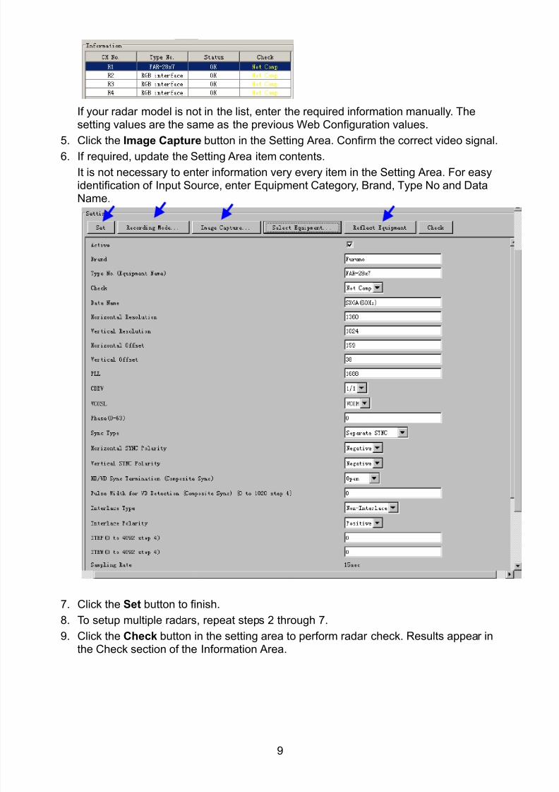
8102019 Ome44376d Vr3000 Mainte Cof26amp3bmol
httpslidepdfcomreaderfullome44376d-vr3000-mainte-cof26amp3bmol 1157
9
If your radar model is not in the list enter the required information manually Thesetting values are the same as the previous Web Configuration values
5 Click the Image Capture button in the Setting Area Confirm the correct video signal6 If required update the Setting Area item contents
It is not necessary to enter information very every item in the Setting Area For easyidentification of Input Source enter Equipment Category Brand Type No and DataName
7 Click the Set button to finish
8 To setup multiple radars repeat steps 2 through 7
9 Click the Check button in the setting area to perform radar check Results appear inthe Check section of the Information Area
8102019 Ome44376d Vr3000 Mainte Cof26amp3bmol
httpslidepdfcomreaderfullome44376d-vr3000-mainte-cof26amp3bmol 1257
10
To import the exact settings to another ship save the settings of the device in the Setting Area to the PC database
1 Click on Reflect Equipment
2 Copy the file to the PC by using Maintenancegt Equipment Managementgt Export inthe menu
3 Import to the other shiprsquos VDR from the PC
How to Set the Record Pattern
When there are two or more Radar units connected to the VDR select which radar torecord to
Note When using a 6 GB DRU it possible to record to 1 channel and when using a 9 GBDRU it is possible to record to 2 channels
1 In the Setting Area click the Recording Mode button The following dialogue boxappears
R1-R4 1st Radar (CH No1)~4
th Radar (CH No4)
G Records signal to the youngest radar number in a group pattern (ex R1-R4 aregrouped) If the youngest number is inactive signal is recorded to the next youngestnumber in sequence within the group
I Indicated unit recordssends
N Indicated unit does not recordsend
2 Select a recording pattern from Patterns 1-4
For example the settings in the above illustration are as follows
Recording Pattern 1 R1 signal is recorded to DRU R2 ndash R4 do not record
R1 and R2 signals are recorded to the Backup HDD R3ndashR4 donot record
Network Sending R1-R4 all send to network
Recording Pattern 3 Recording signal to the DRU automatically routes to the nextyoungest active number in the group between R1 and R3 R4 Does not recordExample If R1 is inactive signal is recorded to R2
Recording to Backup HDD Same as DRU
Send to Network R1-R4 all is sent to the network
3 Update I and N as needed
8102019 Ome44376d Vr3000 Mainte Cof26amp3bmol
httpslidepdfcomreaderfullome44376d-vr3000-mainte-cof26amp3bmol 1357
11
Place the cursor above either I or N and left click to alternate With this I is set torecord while N is set to not record G cannot be changed
4 After completing setup click the OK button
5 To record settings to the database click Reflect Equipment in the Setting Area
How to Enter Information Manually
This VDR system receives in VESA (Video Electronics Standards Association) signal Image signal 05-1Vpp (When using composite signal the minimum synchronization
signal is 50 mV)
Horizontal Synchronization Signal Max plusmn91146 kHz
Vertical Synchronization Signal Max 35 Hz
Acceptable Image Resolution 640x480 ndash 1280x1024
Channel number conforms to the number displayed by the DCU
To set the Radar tab do the following
1 Click the Radar tab
2 Choose the channel with the entered Radar Image from the Information Area
3 Check the Active box in the Setting Area and enter the Horizontal and Verticalresolution of the incoming image in the Horizontal resolution and Vertical resolutioncolumns
4 Click the Set button
5 Click the Image Capturehellip button The Image Capture dialogue box appears
6 Click the Test button in the Image Capture window Radar image appears a fewseconds later
7 If the image is normal close the Image Capture window8 Input each item in the Setting Area
8102019 Ome44376d Vr3000 Mainte Cof26amp3bmol
httpslidepdfcomreaderfullome44376d-vr3000-mainte-cof26amp3bmol 1457
12
Items are as follows
Active Check a channel to activate it
Brand Enter brand nameType No Enter type noCheck Set and activate checkData Name Enter data nameHorizontal resolution Set horizontal resolutionVertical resolution Set vertical resolutionHorizontal Offset Move the picture horizontallyVertical offset Move the picture verticallyPLL This sets the frequency of the PLL-oscillatorCDEV Set CDEV
VCOSL Set VCO Signal LeadPhase (0-63) Phase setting selects the phase of the sampling clock relativeto phase locked loop signal in 64 steps of 5625 degrees IfPhase is not set correctly any section of an image consistingof vertical lines may show line ldquotearingrdquo
Sync Type Select the type of video sync signalHorizontal sync polarity Set the polarity of the horizontal sync signalVertical sync polarity Set the polarity of the vertical sync signalHDVD Sync Termination Sets horizontal and vertical synchronization point When
using a composite signal set to 75ohmsPulse Width for VD Detection (0-1020 Step4) Sets the pulse width for video signal
detectionInterlace Type When the video image is interlace set ldquoInterlaceldquo sampling
mode In Interlace mode the even pixels are sampled on oneframe and odd pixels are sampled on the other frame
8102019 Ome44376d Vr3000 Mainte Cof26amp3bmol
httpslidepdfcomreaderfullome44376d-vr3000-mainte-cof26amp3bmol 1557
13
Interlace Polarity Set interlace polarityITRP (0-4092 Step4) Enter interlace pulse positionITRW (0-4092 step4) Enter interlace pulse widthSampling Rate Display sampling rate Fixed at ldquo15 secondsrdquoCompress Type (viewer) Set compress type (viewer)Color Bit Display and set Color BitChange Pump Current Set pump current Fixed at ldquo05 mArdquo
Video Clock Polarity Set video clock polarity Fixed at ldquoThroughrdquoCounter Clock SelectionSelect counter clock selection Fixed at ldquo49 MHzrdquoVCO Clock Hold Sets VCO clock holdRed Gain (0-255) Enter red gainGreen Gain (0-255) Enter green gainBlue Gain (0-255) Enter blue gainRed Offset (0-255) Enter red offsetGreen Offset (0-255) Enter green offsetBlue Offset (0-255) Enter blue offsetBlack Level (0-255) Enter black levelEquipment Category Enter equipment category
Board Name Enter board name for corresponding channelNote Enter note
Note Offset Phase and Color Bit change with the length of the antenna cable
Marked Items For easy identification of input source enter Equipment Category Brand
Type No and Data Name
Measurement BoxThe Measurement Box is located on the left side of the Information Area The LOWHorizontal and Vertical counter should be higher than the HIGH counter If reversely the
HIGH counter is higher than the LOW counter it is possible that the SYNC Polaritysettings are adjusted incorrectly
8102019 Ome44376d Vr3000 Mainte Cof26amp3bmol
httpslidepdfcomreaderfullome44376d-vr3000-mainte-cof26amp3bmol 1657
14
Config Management
After all items have been set up proceed to the final setting management This can only
be executed one time after all tabs have been set up
1 Click on VDR Config Management in the Maintenance menu
2 Click on the Upload button to send all sent data to the VDR memory
3 Click each individual Write button to record to DRU Backup HDD and CF Note
If the settings are not uploaded to the VDR they have no effect on the unit
4 Click the Close button to close the VDR Config Management Dialogue Box
8102019 Ome44376d Vr3000 Mainte Cof26amp3bmol
httpslidepdfcomreaderfullome44376d-vr3000-mainte-cof26amp3bmol 1757
15
23 Serial Signal
The Serial tab sets the RS-422 signals received at the terminal board (SI01-SI08) and the
junction box (SI09-SI72) This channel is not only for NMEA but also binary and ASCII
data
Set the Serial tab as follows1 Click the Serial tab
2 Select a channel from the Information window
3 Click the Select Equipment button in the Setting Area
4 Choose the unit that is connected to the indicated Channel and click the OK Button
5 Adjust items as needed in the Setting Area
8102019 Ome44376d Vr3000 Mainte Cof26amp3bmol
httpslidepdfcomreaderfullome44376d-vr3000-mainte-cof26amp3bmol 1857
16
6 After finishing the settings for one channel click the Set buttonNote Be sure to do this before moving another channel
7 Repeat steps 2-6 to set up each channel
When running Config Management for Tab Settings
1 From the Maintenance menu click VDR Config Management and then Config
2 Click the Upload button to record data to the VDR memory3 Click the Write button to save data to the DRU backup HDD and CF
The buttons in the Setting Area are as followsSet Save edited dataCapture Received data shown in the serial window dialog boxSelect Equipment Select equipment settings (saved to the database) to reflect in
a channelReflect Equipment Save the equipment setting data to the databaseCheck Check all channels OK or NG (No Good) shown in
Information window
Individual Item ExplanationActive Put check in check box to make channel activeBrand Enter brand nameType No (Equipment Name) Set type no (equipment name)Check Do equipment checkData Name Enter data nameData Type Enter data typeBaud Rate Set baud rate (Available for SI01 to SI08)Data Bit Set number of bits (Available for SI01 to SI08)Parity Bit Set parity bit (Available for SI01 to SI08)Stop Bit Set stop bit (Available for SI01 to SI08)Source Checksum Enter checksum for GPS sourceTime out Set time outEquipment Category Set equipment categoryBoard Name Enter board names where channels are presentNote Enter note
Marked Items For easy identification of input source enter Equipment Category Brand
Type No Date and Name
8102019 Ome44376d Vr3000 Mainte Cof26amp3bmol
httpslidepdfcomreaderfullome44376d-vr3000-mainte-cof26amp3bmol 1957
17
24 Analog SignalAnalog signal is input via Junction Box IF-8530 (optional for VR-3000S)Receivable signal ndash10 to +10 V or 4 to 20mA
Connect the analog signal to V and G terminals on the Junction Box When 4 to 20 mAsignal is connected make a short circuit between the V and I input terminals with jumper
wireThe basic procedure for setting up the analog signal is as follows
1 Click the Analog tab
2 Select channel from the Information Area
3 Set detailed information of the selected channel in the Setting Area Refer to thefollowing illustration to enter detailed item information
In the factory settings there is no preset data when the Select Equipment button is
pressed In the case that the setup was completed on another ship and saved usingReflect Equipment import the data by clicking Select Equipment and choosing thesaved data
4 In the following order calibrate the Analog signal
① Click the Calibration button in the Setting Area
② Enter the voltage (or current) value for Calibration Point 1 and thecorresponding engineering value in the left and right boxes
③ Enter values for Calibration Point 2④ Enter unit for the values in Engineering Value Unit
8102019 Ome44376d Vr3000 Mainte Cof26amp3bmol
httpslidepdfcomreaderfullome44376d-vr3000-mainte-cof26amp3bmol 2057
18
In the above image the Engineering Value Unit is set to degrees (deg) TheCalibration Point 1 is -10V corresponding to 0 degrees Calibration Point 2 is10V corresponding to 30 degrees This is set corresponding to the connectedanalog sensor
When the Apply button is clicked the New Engineering Value of 29835Vcorresponding to the input Voltage of 989V is displayed in the bottom fieldWhenever the input value is changed this value also changes Check that theNew Engineering Value is within an appropriate range
Another method is to observe the Voltage (or Current) field in the top field andpress the Hold button of Point 1 when an appropriate value is displaying Dothis again for Point 2
⑤ Click the OK Button
5 When setting is complete click the Set button Be sure to do this before movinganother to channel
6 Repeat steps 1-5 to set up all channels
When using Config Manager with Tabs
1 From the Maintenance menu click VDR Config Management and then Config
2 Click the Upload button to record to VDR memory
3 Click the Write buttons to record to DRU Backup HDD and CF memory
The items in the Setting Area are as shown below Active Put check in check box to make channel activeBrand Enter brand name
Type No Set type no (equipment name)
Check Do equipment checkData Name Enter data nameData Type Analog Data type (0~10V -10~10v 4~20mV)
Sampling Rate Display sampling rateCalibration Active Disable and enable analog calibrationCalibration Point 1 Enter calibration point 1
Calibration Point 1 Value Enter calibration point 1 valueCalibration Point 2 Enter calibration point 2Calibration Point 2 Value Enter calibration point 2 valueEngineering Value Unit Enter engineering value unit
8102019 Ome44376d Vr3000 Mainte Cof26amp3bmol
httpslidepdfcomreaderfullome44376d-vr3000-mainte-cof26amp3bmol 2157
19
Note For -marked boxes values that are set at the Analog Calibration dialog box aredisplayed
Equipment Category Set equipment categoryBoard Name Enter board names where channels are presentNote Enter note
Marked Items For easy identification of input source enter Equipment CategoryBrand Type No Data and Name
25 Digital Signal
Digital signal is connected via Junction Box IF-8530 (optional for VR-3000S) The
receivable signal is 10-32 V for voltage signal or contact signal For voltage signal
connect to A and B input terminals on the Junction Box For contact signal connect to B
and G input terminals on the Junction Box Also make a short-circuit between the 24 and
A input terminals with a jumper wire
To set up the Digital tab
1 Click the Digital tab
2 Select a channel from the Information Area
3 Set up the digital signal from the Setting Area Refer to the following individual item
explanation
In the factory settings there is no preset data when the Select Equipment button is
pressed In the case that the setup was completed on another ship and saved using
Reflect Equipment import the data by clicking Select Equipment and choosing the
saved data
4 When setting Digital Signal to each 64 channel group perform the following
directions1 Click the Calibration button in the setting area
8102019 Ome44376d Vr3000 Mainte Cof26amp3bmol
httpslidepdfcomreaderfullome44376d-vr3000-mainte-cof26amp3bmol 2257
20
2 Check the active column of the channel group being set
3 Enter the status in columns 0 and 1 of that group
4 Click the OK Button
5 When finished setting up click the Set button
6 Repeat steps 2-5 to set up other channels
When using Config Manager with Tabs
1 From the Maintenance menu click VDR Config Management
2 Click the Upload button to record to VDR memory
3 Click the Write buttons to record to DRU Backup HDD and CF memory
The items in the Setting Area are as shown below
Active Put check in check box to make channel activeBrand Enter brand name
Type No Set type no (equipment name)Check Do equipment checkData Name Enter and display data nameContact Type Set contact type NO normal open NC normal closeSampling Rate Display sampling rateCalibration Active Disable and enable digital calibrationActive Status (1) Set status display when (1) is activeActive Status (0) Set status display when (0) is activeEquipment Category Set equipment categoryBoard Name Enter board names where channels are presentNote Enter note
Marked Items For easy identification of input source enter Equipment CategoryBrand Type No Date and Name
8102019 Ome44376d Vr3000 Mainte Cof26amp3bmol
httpslidepdfcomreaderfullome44376d-vr3000-mainte-cof26amp3bmol 2357
21
26 Audio
Microphone and VHF audio settings are performed in the Audio tab
Set the items in the Audio tab as shown below
1 Click the Audio tab
2 Select channel from the Information Area3 Click Select Equipment in the Setting Area
4 Click on the connected device in the indicated channel The setting contents aredisplayed in the Information and Setting Areas
5 If required update the item contents in the Setting Area Refer to the detailed itemexplanation below
6 After completing settings for a channel click the Set buttonNote Be sure to click the Set button before moving to another channel
7 Repeat steps 2-6 to set up other channels
8102019 Ome44376d Vr3000 Mainte Cof26amp3bmol
httpslidepdfcomreaderfullome44376d-vr3000-mainte-cof26amp3bmol 2457
22
When using Config Manager with tabs
1 From the Maintenance menu click VDR Config Management
2 Click the Upload button to record to VDR memory
3 Click the Write buttons to record to DRU Backup HDD and CF memory
MIC testDo the MIC test to check whether audio is received clearly in adequate level or not
1 Click the MIC TEST button in the Setting Area
2 Click the TEST button in the MIC Test dialogue box MIC test results are displayed in
the MIC Test dialogue box
3 Click the Close button to close the dialogue box
Note Not the same recordingplayback function as the previous Web Configuratorsoftware
Continuous MIC TestRun the continuous MIC test as needed accordingly
1 Click the Continuous MIC Test button in the Setting Area2 Set up how many times to perform in the Continuous MIC Test dialogue box and click
the Test button
3 Click the Close button to close the dialogue box
8102019 Ome44376d Vr3000 Mainte Cof26amp3bmol
httpslidepdfcomreaderfullome44376d-vr3000-mainte-cof26amp3bmol 2557
23
Active Put check in check box to make channel activeBrand Enter and display brand nameType No Set type no (equipment name)Check Do equipment checkData Name Enter data nameInput Type Enter input type Sampling Data Bit Displays sampling data bit rate
Sampling Frequency Displays Sampling FrequencyCodec Sets MIC typeMIC Test Active M1M3M5 Put a checkmark when performing MIC Test of M1M3M5MIS Test Active M2M4M6 Put a checkmark when performing MIC Test of M2M4M6 MIC M1M3M5 Position Enter MIC position of MIC M1M3M5MIC M2M4M6 Position Enter MIC position of MIC M2M4M6Threshold Level M1M3M5 Enter MIC test threshold level of MIC M1M3M5Threshold Level M2M4M6 Enter MIC test threshold level of MIC M2M4M6Equipment Category Set equipment categoryBoard Name Enter board names where channels are present
Note Enter note Marked Items For easy identification of input source enter Equipment Category BrandType No Date and Name
8102019 Ome44376d Vr3000 Mainte Cof26amp3bmol
httpslidepdfcomreaderfullome44376d-vr3000-mainte-cof26amp3bmol 2657
24
27 Alarm
Alarm and Alarm Status settings are found in the Alarm tab
The Alarm tab shows the following information about alarms Click the Time Categoryand Name tabs in the title bar to sort
Time Time of alarm
Category Alarm categoryName Name of alarm
Number Alarm number
Status Alarm status
Alarm Search
1 Click the Search button above the Alarm tab The Search dialogue box appears
2 Add a checkmark to any desired search items (multiple items can be selected)
Start Time Display name of alarms generated after a certain time
End Time Display name of alarms generated before a certain time
Name Display information for alarm name entered
8102019 Ome44376d Vr3000 Mainte Cof26amp3bmol
httpslidepdfcomreaderfullome44376d-vr3000-mainte-cof26amp3bmol 2757
25
Number Display information for alarm number entered
Status Display alarm status for alarm name entered
3 In the checked items column input the desired search items
4 Click the Search Button
Close the Search box to cancel a search
Note During a search the upper left Mode changes from Play to Search andDisplay search related information
8102019 Ome44376d Vr3000 Mainte Cof26amp3bmol
httpslidepdfcomreaderfullome44376d-vr3000-mainte-cof26amp3bmol 2857
26
28 Event
Click the items shown below to sort by item selected
Note You can sort the items in ascending order () descending order () and
initialization order (no symbol)
Time Time an event occurred
Category Category of an event
Name Name of an event
Contents1 Display data associated with log
Contents2 Display data associated with log
Event Search
Do the following to search events
1 Click the Search button on the upper right of the Event tab
2 In the dialogue box add a checkmark to desired search items Multiple items can bechecked
Start Time Display name of event generated after a certain time
End Time Display name of event generated before a certain time
Name Display event names entered
Number Display event numbers entered
Status Display event status entered
Enter information about the checked event to search in the character input box
3 Click the Search button
Note The mode changes from Play to Search when performing a search
8102019 Ome44376d Vr3000 Mainte Cof26amp3bmol
httpslidepdfcomreaderfullome44376d-vr3000-mainte-cof26amp3bmol 2957
27
29 Hardware
The Hardware tab provides information about the system hardware
The buttons in the Setting window work as follows
Self Check Status Display status of self check
CPU Display information about the CPU
Memory Size Display memory size
CPU Board Display status of CPU board
Audio Board Display status of Audio board
Serial Board Display status of Serial board
Radar Interface Board Display status of Radar Interface boardNote Enter and display note
Marked items are optional
8102019 Ome44376d Vr3000 Mainte Cof26amp3bmol
httpslidepdfcomreaderfullome44376d-vr3000-mainte-cof26amp3bmol 3057
28
210 JB
Connect the Junction Box to the DCU before turning on the system
The JB tab functions to set up the Junction Box
The basic procedure for setting up the Junction Box is as follows
1 Click the JB tab2 Select a Junction Box from the Information Area
3 Set up the Junction Box from the Setting Area
4 Click the Set button (Be sure to do this before moving to another channel)5 Click the Check button to perform an inspection on all channels In the Information
Area check column either OK or NG (No Good) is displayed
When using Config Manager with Tabs
1 From the Maintenance menu click VDR Config Management
2 Click the Upload button to record to VDR memory
3 Click the Write buttons to record to DRU Backup HDD and CF
The items in the Setting window work as followsActive Put check in check box to make channel activeNo Display Junction Box numberIP Address Display IP address of Junction Box acquired by VDRMAC Address Display MAC address of Junction Box acquired by VDRCheck Enable and disable equipment checkNote Enter note
Marked items are optional
8102019 Ome44376d Vr3000 Mainte Cof26amp3bmol
httpslidepdfcomreaderfullome44376d-vr3000-mainte-cof26amp3bmol 3157
29
211 Life Time
The Life Time tab controls consumable parts
The basic procedure for using the Life Time tab is as follows
1 Click the Life Time tab
2 Select a Type No in the Information Area3 Set up the chosen part from Setting Area
4 Click the Set button
Note Be sure to click the Set button before moving to set up a different Type
The items in the Setting window work as follows
Type No Enter and display type no
Data Name Enter and display data name
Level Set replacement level Legal Exchange Parts or Normal Exchange Parts
Replace Date Enter and display recommended day of replacement
Lifetime Term Not usedNote Enter and display note
The Status column of the Information Area displays as follows
OK The recommended date of replacement shown in the Replace Date
box in the Information window has not passed
Out of Date The date of replacement has passed
None The date of replacement has not been set
8102019 Ome44376d Vr3000 Mainte Cof26amp3bmol
httpslidepdfcomreaderfullome44376d-vr3000-mainte-cof26amp3bmol 3257
30
212 Network
The Network tab sets the system network
The basic procedure for setting up the system network is as follows
1 Click the Network tab
2 Select a port from the Information Area
3 Set up the network from the Setting Area
4 Click the Set button
Note1 Be sure to click the Set button before moving to set up a different Port
Note2 After setting the system network reboot the VDR to apply the settings
The items in the Setting window work as follows
LAN Type Enter LAN type Public LAN or JB LAN
MAC Address Enter MAC address
IP Address Enter IP address
Subnet Mask Enter subnet mask
Gateway Address Enter gateway address
Live Play Multicast Mode (Only JB LAN) Check box to enable live player multicast
mode
Multicast Address (Only Public LAN) Enter and display live player multicast addressNote Enter note
Marked items are optional
8102019 Ome44376d Vr3000 Mainte Cof26amp3bmol
httpslidepdfcomreaderfullome44376d-vr3000-mainte-cof26amp3bmol 3357
31
213 System
The System tab sets system related functions
The basic procedure for using the System tab is as follows
1 Click the System tab
2 Set up the chosen item from the Setting Area
3 Click the Set button
Note Be sure to click the Set button before moving to a different tab
The items in the Setting window work as follows
VDR Type Enter type of VDR
VDR Model Enter model number of VDR
Radar Interface Check Enable and disable checking of the Radar Interface board
Junction Box Count Enter number of junction boxes in system
DRU Flash Count Enter number of DRU flash disks in system Set 1 when DRU
serial no is 5000 and more Set 3 when DRU serial no is less
than 5000
DRU Capacity Display capacity of DRU
Backup HDD Capacity Display capacity of Backup HDD
VDR Config Version Display version no of VDR
VDR Config Date Display the number of hours the VDR settings have
been saved
VDR Config Code Display configuration identity code
Installation Engineer Enter name of the equipment installer
Installation Company Enter name of installers company
8102019 Ome44376d Vr3000 Mainte Cof26amp3bmol
httpslidepdfcomreaderfullome44376d-vr3000-mainte-cof26amp3bmol 3457
32
Installation Date Enter the date of the installation
MIC Test Time Enter the date of the MIC test
Note Enter note Marked items are optional
USB memory logging Do not check Enable
IEEE1394 BUS Error Auto Restart function Not used
IEEE1394 Active Node Count Do not change the default value of 3 (However set to 5
for serial number 5000 or less of DRU)
IEEE1394 Recover Process Limit Count Do not change the default value of 10
DRU Error Auto Restart function Not used
REBOOT DELAY TIME (sec) Do not change the default value of 10
LIMIT REBOOT COUNT Do not change the default value of 10
Live Player Max Connection Count The max number of Live Player V4 that can be
connected simultaneously The default no is two
but a maximum of five can be set here After you
change this option reboot the VDR to apply the
setting Disconnect the cable connected with
Live Player V4 (PC) from the VDR and thenreconnect it
214 Software
The Software tab sets and display software-related operations
The basic procedure for using the Software tab is as follows
1 Click the Software tab
2 Set up the chosen Item from the Setting Area
3 Click the Set button
8102019 Ome44376d Vr3000 Mainte Cof26amp3bmol
httpslidepdfcomreaderfullome44376d-vr3000-mainte-cof26amp3bmol 3557
33
The items in the Setting window work as follows
VDR System Program Display the VDR system program no
Process Version Display the process version
Power Distribution Unit (PDU) Display the version no of the PDU
Operation System Display the version no of the OS
Audio Driver Display the version no of the audio driverRAP Version Enter the version no of the RAP
AP Version Enter the version no of the AP
JB1-8 Boot Program Display the no of the RJB Boot program for Junction Boxes
1 to 8
JB1-8 App Program Display the no of the RJB App program for Junction Boxes
1 to 8
Watch Dog Interval Do not change the default value of 60 (Enter the process
response time A process is repeated if there is no response
within the time interval set here)
Giveup Interval Do not change the default value of 300 (Enter the restart
watch time The restarting of a process is stopped when the
number of times it has been restarted is exceeded within the
interval set here)
Refork Limit Do not change the default value of 10 (Enter the upper limit
for process restart The restarting of a process is stopped
when the number of times it has been restarted exceeds the
Give up Interval)
Note Enter note
Marked Items are optional
8102019 Ome44376d Vr3000 Mainte Cof26amp3bmol
httpslidepdfcomreaderfullome44376d-vr3000-mainte-cof26amp3bmol 3657
34
215 GPS
The GPS tab sets GPS-related parameters
The basic procedure for using the GPS tab is as follows
1 Click the GPS tab
2 Set up the chosen channel from the Information window3 Set up the chosen item in the Setting Area
4 Click the Set button
5 Repeat steps 2-4 to set up each Channel
6 Click the Check button to perform an inspection on all channels In the Information Area check column either OK or NG (No Good) is displayed
The items in the Setting window work as follows
Priority Display priority order
Date and Time SourceShip Position Source Set GPS source channel (serial channel
number for ZDA sentence)
Check Enable and disable checking
GPS Antenna Position From Bow Enter position of GPS antenna from bow
GPS Antenna Position From Stern Enter position of GPS antenna from stern
GPS Antenna Position From Port Enter position of GPS antenna from port
GPS Antenna Position From Starboard Enter position of GPS antenna from starboard
GPS Failure Threshold If the ZDA is input within the set time limit
the system restarts synchronized If not
input within the time limit the system restarts
without synchronization
8102019 Ome44376d Vr3000 Mainte Cof26amp3bmol
httpslidepdfcomreaderfullome44376d-vr3000-mainte-cof26amp3bmol 3757
35
GPS Delay Time by Time Sync Enter minimum time delay for time
synchronization Time synchronization is started
only in the time set here
GPS Difference Interval The time set here is added to the GPS time to
synchronize the system time Leave at the default
0 value setting
GPS Sync Giveup Time If the system receives the GPS time within the
time set the system synchronizes with the time
When not receiving a signal the system displays
an ldquoerror 26rdquo message
ZDA Timeout Enter value (seconds) for ZDA timeout (234 error)
from GPS
Note Enter and display note
Marked Items are optional
216 VesselThe Vessel tab sets and displays own ships information such as name and IMO number
The basic procedure for using the Vessel tab is as follows
1 Click the Vessel tab
2 Set up information in the Setting window
3 Click the Set button (Be sure to do this before moving to another port)
4 From the Maintenance menu click VDR Config Management and then Config5 Click the Write buttons to save data to the DRU backup HDD CF
The buttons in the Setting window works as follows
Vessel Name Enter name of vessel
Vessel IMO Number Enter IMO number of vessel
Vessel Flag Enter flag of vessel
Approval of Authority Enter name of approving authority
Note Enter note
Marked items are optional
8102019 Ome44376d Vr3000 Mainte Cof26amp3bmol
httpslidepdfcomreaderfullome44376d-vr3000-mainte-cof26amp3bmol 3857
36
217 Delivery
The Delivery tab functions to transmit data from the VDR to a PC via Ethernet LAN Do
not use this function during live connection
The basic procedure for using the Delivery tab is as follows
1 Click the Delivery tab
2 Click the Add button to show the Delivery Config window
3 Select protocol from the Protocol drop-down box (Unicast or Multicast)
4 Enter IP address in the IP address input box
5 Enter port number in the port number input box
6 Click the tab of the data to send (Analog Digital or Serial)
7 Select the channel of the data to send
8 If Serial was selected at step 6 select applicable data sentence from the Inactivewindow Click the right arrow to move the data sentence to the Active window
9 Click the OK button to close the Delivery Config window
10 The settings are listed in a table in the Delivery window Check the checkbox in the
Active column and then click the Set button
The buttons in the Setting window works as follows
Set Save edited settings
Add Create new delivery settings
Modify Modify selected delivery settings
Delete Delete selected delivery settings
8102019 Ome44376d Vr3000 Mainte Cof26amp3bmol
httpslidepdfcomreaderfullome44376d-vr3000-mainte-cof26amp3bmol 3957
37
3 How to Back up Configuration DataThis chapter shows how to back up configuration data to various storage media
Configuration data can be opened with Word Pad or any text editor other than Notepad
31 How to Back up Configuration Data to the Startup CompactFlash (CF)
Back up data to the startup CF after setting the VDR Configuration data is created on the
CF as a configini file
Note When the error shown below occurs during the downloading or uploading of
configuration data check the connection of the DRU Backup HDD and CF and then
upload or download the configuration data again
[CONN] Download failed
[CONN] Could not upload config file
If error occurs again re-install the VDR Maintenance Viewer
Do the following to back up data to a CF
1 Set up parameters on the tabs referring to Chapter 2
2 Click the Maintenance menu
3 Select VDR Config Management
4 Click the Upload button
5 A confirmation box appears click the OK button to start uploading to the VDR
6 Click the Write button where the arrow connects between VDR and DRU BackupHDD
7 A confirmation window appears click the OK button to save the configuration data tothe DRU and Backup HDD
8102019 Ome44376d Vr3000 Mainte Cof26amp3bmol
httpslidepdfcomreaderfullome44376d-vr3000-mainte-cof26amp3bmol 4057
38
8 Click the Write button where the arrow connects between the VDR and CF
9 A confirmation window appears click the OK button to save the configuration data tothe startup CF
10 Check that the PC VDR DRU Backup HDD and CF share the same VDR configcode
32 How to Back up Configuration Data to a PC
Configuration data saved to the PC can be edited with Wordpad and shared with other
vessels For future service ease it is recommended to backup configuration data to the
PC and have the data on board the vessel Also it is recommended to upload this data to
Furuno SMS (Service Management System) If unable to upload to Furuno SMS please
contact the Service Center Furuno Japan
To back up configuration data to the PC do as follows
1 Set up parameters on the tabs referring to Chapter 2
2 Click the Maintenance menu
3 Select VDR Config Management
4 Click the Export to button
5 A confirmation window appears click the OK button
6 Select where to save the data enter file name then click the Open button
7 Confirm that back up file is in the location selected
33 How to restore the default settings
Click the Default button on the VDR Config Management window to restore the default
settings of the DRU Backup HDD CF and VDR Maintenance Viewer
8102019 Ome44376d Vr3000 Mainte Cof26amp3bmol
httpslidepdfcomreaderfullome44376d-vr3000-mainte-cof26amp3bmol 4157
39
4 How to Upload Configuration Datafrom a PCThe procedure below shows how to upload configuration from the PC to aVR-3000VR-3000S
1 Click the Maintenance menu
2 Select VDR Config Management
3 Click the Import from button
4 The Open window appears Select configuration data and then click the Open button
5 Click the Upload button to upload data to the VR-3000VR-3000S
6 Click the Write buttons to save data to the DRU backup HDD and CF
8102019 Ome44376d Vr3000 Mainte Cof26amp3bmol
httpslidepdfcomreaderfullome44376d-vr3000-mainte-cof26amp3bmol 4257
40
5 Media ManagementThe media management feature deletes data from recording media initialization the
system etc There are two method LAN connection and Direct connection The Direct
connection takes longer time than the LAN connection Basically use the LAN connection
method
Note Initialization or creation of recording media is not available when Source Select onthe Live Player V4 is selected to Backup HDD
51 Initialization
This section shows how to delete data from the recording media Configuration data is
not deleted After performing the software configuration delete the data from the DRU
and HDD
Do the following to delete data from the DRU (LAN connection)
1 Set the PlaybackCPU switch in the DCU to the CPU position
2 Use an Ethernet cross cable to connect the PC to J14 (DATA) in the DCU (See page5)
3 Open the Tool menu
4 Select Media Management to open the VDR Media Management window
5 Check that IP address shown in the ldquoLAN Connect to IPrdquo in VDR Media Table Area isthe same as the IP address access point
6 Select ldquoLAN Connect to IPrdquo in the VDR Media Table column
8102019 Ome44376d Vr3000 Mainte Cof26amp3bmol
httpslidepdfcomreaderfullome44376d-vr3000-mainte-cof26amp3bmol 4357
41
7 Click the Analyze button A list of recording media connected to the VDR appears
Put a checkmark in the checkbox of the Select column for the DRU in the Name columnNote If there are several flash memories in the DRU all flash memories are shownCheck all flash memories shown
8 Select ldquoDRU Initializerdquo from the Operation dropdown list in the Operation area
10 Click the Run button
Do the following to delete data from the DRU (Direct connection)
1 Start Live Player V4 software
2 Open the Tool menu and select Source Select Select Live from the pull-downmenu
3 Click the Alarm tab and open Alarm History
4 Set the PlaybackCPU switch in the DCU to the Playback position
5 Wait approx 10 minutes and confirm that Alarm 174 occurs on Alarm History of LivePlayer V4
6 Connect an IEEEE1394 cable between J6 in the DCU and the PC
7 Open the Tool menu
8 Select Media Management to show the VDR Media Management window
9 Select Direct in the VDR Media Table column
10 Click the Analyze button A list of recording media connected to the VDR appears
11 Put a checkmark in the checkbox of the Select column for the DRU in the Namecolumn
Note If there are several flash memories in the DRU all flash memories are shownCheck all flash memories shown
12 Select ldquoDRU Initializerdquo from the Operation dropdown list in the Operation area
13 Enter password in the password column
14 Click the RUN button
8102019 Ome44376d Vr3000 Mainte Cof26amp3bmol
httpslidepdfcomreaderfullome44376d-vr3000-mainte-cof26amp3bmol 4457
42
Delete data from the Backup HDD as follows (LAN connection)
1 Set the PlaybackCPU switch in the DCU to the CPU position
2 Check that an Ethernet cross cable is connected between J14 in the DCU and the PC
3 Open the Tool menu
4 Select Media Management to open the VDR Media Management window
5 Check that IP address shown in the LAN Connect to IP in VDR Media Table Area is
the same as the IP address access point6 Select LAN Connect to IP in the VDR Media Table column
7 Click the Analyze button
8 A list of recording media connected to the VDR appears
9 Put a checkmark in the box of the Select column for the Backup HDD in the Namecolumn Select ldquoBackup HDD Initializerdquo from the Operation dropdown list in theOperation area
10 Click the Run button
Delete data from the Backup HDD as follows (Direct connection)
1 Start Live Player V4 software
2 Open the Tool menu and select Source Select Select Live from the pull-downmenu
3 Click the Alarm tab and open Alarm History
4 Set the PlaybackCPU switch in the DCU to the Playback position
5 Wait approx 10 minutes and confirm that Alarm 174 occurs on Alarm History of LivePlayer V4
6 Connect an IEEE1394 cable between J6 in the DCU and the PC
7 Open the Tool menu
8 Select Media Management to open the VDR Media Management window9 Select Direct in the VDR Media Table window
10 Click the Analyze button A list of recording media connected to the VDR appears
11 Put a checkmark in the check box of the Select column for the Backup HDD in theName column Select ldquoBackup HDD Initializerdquo from the Operation dropdown list in theOperation area
12 Enter password
13 Click the Run button
8102019 Ome44376d Vr3000 Mainte Cof26amp3bmol
httpslidepdfcomreaderfullome44376d-vr3000-mainte-cof26amp3bmol 4557
43
52 CreationThe Creation feature initializes recording media
Note1 This feature deletes ALL configuration data Backup all VDR configuration data
Note2 When you initialize medium that is a different format for the DRU or Backup HDDdelete all partitions with the disk management tool of Windows
Note3 When the Creation is failed try again If you can not initialize recording media tryunder condition as shown below
Do the Creation by the direct connection (When the Creation by the LAN
connection is failed)
Delete all partitions of the DRU or Backup HDD with the disk management tool of
Windows to do the Creation
If the Creation is still failed request service to repairreplace the DRU or Backup
HDD
Initialize the DRU as follows (LAN connection)
1 Set the PlaybackCPU switch in the DCU to the CPU position
2 Check that an Ethernet cross cable is connected between J14 in the DCU and the PC
3 Open the Tool menu
4 Select Media Management to open the VDR Media Management window
5 Check that IP address shown in the LAN Connect to IP in VDR Media Table Area isthe same as the IP address access point
6 Check ldquoLAN Connect to IPrdquo in the VDR Media Table column
7 Click the Analyze button A list of recording media connected to the VDR appears
8 Put a checkmark in the box of the Select column for the DRU in the Name column
Select ldquoDRU Creationrdquo from the Operation dropdown list in the Operation area
9 Click the Run button
Initialize the Backup HDD as follows (LAN connection)
1 To format the Backup HDD place a checkmark in the Select column of the listedrecord media in the Name column of the VDR Media Management dialogue box
2 From the Operation drop down list of the Operation area select ldquoBackup HDDCreation (Radar) or ldquoBackup HDD Creationrdquo
Two partition tools are available for the Backup HDD in the Media Management as
below
Backup HDD creation
This tool is used when the number of the SXGA video signal connected to the BackupHDD is the same as the DRU The same partition is created on both DRU and HDD
(1) When two SXGA video signals are recorded onto the HDD while 9-GB DRU isconnected
(2) When an SXGA video signal is recorded onto the HDD while 6-GB DRU isconnected
Backup HDD creation (radar)
This tool is used when two SXGA video signals are recorded onto the HDD with 6-GB
DRU connected The HDD has an area (radar) to record the second radar signal inaddition to the same partition as the DRU This tool cannot be used when 9-GB DRUis connected
3 Press the Run Button
8102019 Ome44376d Vr3000 Mainte Cof26amp3bmol
httpslidepdfcomreaderfullome44376d-vr3000-mainte-cof26amp3bmol 4657
44
Initialize the DRU as follows (Direct connection)
1 Start Live Player V4 software
2 Open the Tool menu and select Source Select Select Live from the pull-downmenu
3 Click the Alarm tab and open Alarm History
4 Set the PlaybackCPU switch in the DCU to the Playback position
5 Wait approx 10 minutes and confirm that Alarm 174 occurs on Alarm History of LivePlayer V4
6 Connect an IEEE1394 cable between J6 in the DCU and the PC
7 Open the Tool menu
8 Select Media Management to open the VDR Media Management window
9 Select Direct in the VDR Media Table window
10 Click the Analyze button A list of recording media connected to the VDR appears
11 Put a checkmark in the box of the Select column for the DRU and the desiredrecording media in the Name column In the Operation dropdown list of the Operationarea select ldquoDRU Creationrdquo
12 Enter password in the password column
13 Click the Run button
Initialize the Backup HDD as follows (Direct Connection)
1 To format the Backup HDD place a checkmark in the Select column of the listedrecord media in the Name column of the VDR Media Management dialogue box
2 From the Operation column of the Operation area select ldquoBackup HDD Creation(Radar) or ldquoBackup HDD Creationrdquo
Backup HDD creation
This tool is used when the number of the SXGA video signal connected to the BackupHDD is the same as the DRU The same partition is created on both DRU and HDD
(1) When two SXGA video signals are recorded onto the HDD while 9-GB DRU is
connected
(2) When an SXGA video signal is recorded onto the HDD while 6-GB DRU is
connected
Backup HDD creation (radar)
This tool is used when two SXGA video signals are recorded onto the HDD with 6-GBDRU connected The HDD has an area (radar) to record the second radar signal inaddition to the same partition as the DRU This tool cannot be used when 9-GB DRUis connected
3 Enter the password in the Password column
4 Press the Run Button
8102019 Ome44376d Vr3000 Mainte Cof26amp3bmol
httpslidepdfcomreaderfullome44376d-vr3000-mainte-cof26amp3bmol 4757
45
53 How to Enable Recording Area on the Backup HDD
This function enables writing over a recording area To prevent falsification of data all
recording areas must be saved otherwise this function is disabled To use this function push
the SAVE button Save the data before doing this procedure
Note Software version 135 or higher can enable writing over a recording area even if
all recording areas are not saved
Recording enable (LAN connection)
1 Set the PlaybackCPU switch in the DCU to the CPU position
2 Check that an Ethernet cross cable is connected between J14 in the DCU and the PC
3 Open the Tool menu
4 Select Media Management to open the VDR Media Management window
5 Check that IP address shown in the ldquoLAN Connect to IPrdquo in VDR Media Table Area isthe same as the IP address access point
6 Select ldquoLAN Connect to IPrdquo in the VDR Media Table column7 Click the Analyze button A list of recording media connected to the VDR appears
8 Put a checkmark in the box of the Select column for the Backup HDD in the Namecolumn
9 Select ldquoBackup HDD Recording Area Enablerdquo from the Operation dropdown list in theOperation area
10 Click the Run button
Recording enable (Direct connection)
1 Start Live Player V4 software
2 Open the Tool menu and select Source Select Select Live from the pull-down menu3 Click the Alarm tab and open Alarm History
4 Set the PlaybackCPU switch in the DCU to the Playback position
5 Wait approx 10 minutes and confirm that Alarm 174 occurs on Alarm History of LivePlayer V4
6 Connect an IEEE1394 cable between J6 in the DCU and the PC
7 Open the Tool menu
8 Select Media Management to open the VDR Media Management window
9 Select Direct in the VDR Media Table window
10 Click the Analyze button A list of recording media connected to the VDR appears11 Put a checkmark in the box of the Select column for the Backup HDD in the Name
column
12 Select ldquoBackup HDD Recording Area Enablerdquo from the Operation dropdown list in theOperation area
13 Enter password
14 Click the Run button
8102019 Ome44376d Vr3000 Mainte Cof26amp3bmol
httpslidepdfcomreaderfullome44376d-vr3000-mainte-cof26amp3bmol 4857
46
6 Other Functions
61 Software Management
The software download feature downloads VDR system software to the PC
To download software
1 Click the Maintenance menu
2 From the Software Management menu click Software Download to show theSoftware Download window
3 Enter the IP address 1000100 in the IP address box in the Update Server area
4 Click the Download Software button
5 The confirmation window appears click the OK button
The Software Backup Execute window shows the results of the download
Software is downloaded to C Program Files VDR Viewer Viewer Backup The software file
name is vdrtar
To Update Software
VDR system program version 16x can update the software with the procedure shownbelow
Note Do not update the file downloaded in procedures above
1 Click the Maintenance menu
2 From the Software Management menu click Software Upload to show the SoftwareUpload area
3 Click the Select button to show the Open window
4 Select update file (vdrtar) and click the Open button
8102019 Ome44376d Vr3000 Mainte Cof26amp3bmol
httpslidepdfcomreaderfullome44376d-vr3000-mainte-cof26amp3bmol 4957
47
5 Check the displayed Software information is correct
6 Enter the IP address 1000100 in the IP address box in the Update Server area
7 Enter password
8 Click the Update button
After the updating is completed the VDR is automatically restarted
Note Click the Restore button on the Software Update window to restore previoussoftware version This feature is available after updating the software
62 Password Management
The password can be changed for a serviceman to access the equipment Contact
FURUNO to get the default password to use during installation
Serviceman password
1 Click the Maintenance menu2 Select Change Serviceman Password from Password Management to show the
Change Serviceman Password window
3 Enter current password in the Old Password box
4 Enter the new password in the New Password box of the Change Password area
5 Enter new password again in the Confirm New Password box
6 Click the OK button
Audio password
The audio password set at the VDR Maintenance Viewer can be removed to enable
audio access without password1 Click the Maintenance menu
2 Select Change Audio Password from Password Management to show the Change Audio Password window
3 The confirmation window appears click the OK button
8102019 Ome44376d Vr3000 Mainte Cof26amp3bmol
httpslidepdfcomreaderfullome44376d-vr3000-mainte-cof26amp3bmol 5057
48
63 Record ComparisonThe integrity of the DRU and Backup HDD recordings can be compared This function isused by the RampD engineer for debugging
Follow the procedure as shown below
1 Click the Maintenance menu2 Select Record Comparison to show the Record Comparison window
The results are shown every 15 seconds in the Record Comparison window
8102019 Ome44376d Vr3000 Mainte Cof26amp3bmol
httpslidepdfcomreaderfullome44376d-vr3000-mainte-cof26amp3bmol 5157
49
64 Software History
This section shows you to save and configure software history (communications record)
How to save software history
Note When the error dialog appears while saving the software history restart the VDR
Maintenance Viewer
1 Click the Maintenance menu
2 Select Software History Collect
3 Click the Select button The Open dialog box appears
4 Select where to save the data then click the Open button
5 Select desired save condition then click the OK buttonNone No savingAt Once Save the software history manually Saving begins as soon as the OK button is clickedPeriodic For debugging Do not use otherwise The intervals are 30 sec 60 secand 120 secAlarm Detection For debugging Do not use otherwise Software history is savedwhen specified alarm is released Enter alarm number
How to configure software communications record
The RampD engineer uses this function for debugging Do not do this procedure unless
required Malfunction can result
1 Click the Maintenance menu
2 Select Software History Config
3 Do the followingProcess Select the type of communications record to save ALL saves allcommunications records
Detail Hide or show detailed information4 Click the Send button
8102019 Ome44376d Vr3000 Mainte Cof26amp3bmol
httpslidepdfcomreaderfullome44376d-vr3000-mainte-cof26amp3bmol 5257
50
65 Easy SetupThis feature sets equipment settings in batch and creates a data file of those settings
Default template The default template is created with the settings entered at installation
1 Click the Maintenance menu
2 Select Easy Setup to show the Template Selection window
3 Select Default Template
4 Click the Start button to show the Easy Setup window
5 Right click the channels (Radar Audio Digital Serial Analog) then select Edit toshow the Equipment Selection window
6 From the Equipment Directory window select equipment connected to the selectedchannel and then click the OK button
7 Repeat steps 5 and 6 to select equipment settings for each channel
8 Click the Save button in the Easy Setup window to show the Save window
9 Select where to save the file and enter file name
10 Click the Save button
8102019 Ome44376d Vr3000 Mainte Cof26amp3bmol
httpslidepdfcomreaderfullome44376d-vr3000-mainte-cof26amp3bmol 5357
51
Specific template Use a file already created
1 Click the Maintenance menu
2 Select Easy Setup to show the Template Selection window
3 Check Specified Template
4 Click the Select button and then select the file to edit
5 Click the Start button to show the Easy Setup window
6 Right click the channels (Radar Audio Digital Serial Analog) then select Edit toshow the Equipment Selection window
7 From the Equipment Directory window select equipment connected to the selectedchannel and then click the OK button
8 Repeat steps 6 and 7 to select equipment settings for each channel
9 Click the Save button in the Easy Setup window to show the Save window
10Select where to save the file and enter file name
11 Click the Save button
66 Equipment Management
This feature controls the import and export of equipment settings
Import data file
Import data files of equipment settings created in Easy Setup etc to the VDR
1 Click the Maintenance menu
2 Select Import from Equipment Management to show the Open window
3 Select the data file to import and click Open
Export data file
Export data files of equipment settings from the VDR to a PC
1 Click the Maintenance menu
2 Select Export from Equipment Management to show the Save window
3 Enter file name
4 Click the Save button
8102019 Ome44376d Vr3000 Mainte Cof26amp3bmol
httpslidepdfcomreaderfullome44376d-vr3000-mainte-cof26amp3bmol 5457
52
67 PC_RAP
This feature enables the same operation of the RAP (Remote Alarm Panel) from a PC
Select PC_RAP from the Tool menu to show the PC_RAP window
The buttons in the PC_RAP window function as shown below
SAVE Stop recording in the area where recording is currently being done
ACK Silence audio alarm
The PC_RAP display shows the following information with LEDs
RAP_LEDs Display the status of LEDs on the RAPSave The Save button blinks yellow when pushed When the 4 memory
areas have data recorded to them the Save button lights orange when
pushed
Normal Lights (green) where there are no unconfirmed or not restored
alarms
Error Flashes (red) for not confirmed alarm Lights (red) for unrestored
alarm
8102019 Ome44376d Vr3000 Mainte Cof26amp3bmol
httpslidepdfcomreaderfullome44376d-vr3000-mainte-cof26amp3bmol 5557
53
Backup HDD Information Display status of backup HDD
Selected Display current recording area and its status in green for
normal operation and in red for abnormal operation
Size Display capacity of backup HDD
Alarm area displays unconfirmed alarms
Time Display time alarm was generatedNumber Display number of alarm
Name Display name of alarm
Pending Alarm displays the unrestored alarms out of confirmed alarms only
Time Display time alarm was generated
Number Display number of alarm
Name Display name of alarm
8102019 Ome44376d Vr3000 Mainte Cof26amp3bmol
httpslidepdfcomreaderfullome44376d-vr3000-mainte-cof26amp3bmol 5657
54
68 Other
Status Monitor
The status monitor feature provides comprehensive data about the status of the VDR
From the menu bar click Toolgt Status Monitor to show the Status Monitor window
The buttons in the Status Monitor window work as shown below
Reload Settings for automatic refreshing of the status monitor
ON Turn automatic refresh OFF
OFF The Status Monitor is refreshed every five seconds
Save Available when Reload ON is selected The contents of the Status Monitor can be
saved to a text fileUpdate Update the Status Monitor display
Close Close the Status Monitor display
8102019 Ome44376d Vr3000 Mainte Cof26amp3bmol
httpslidepdfcomreaderfullome44376d-vr3000-mainte-cof26amp3bmol 5757
VDR Error List
This feature compiles all the errors shown on the RAP for easy reference
Access from MenugtToolgtVDR Error List
The VDR error list contains the following information
NO Display the number of the error
Title Display the name of the error
Detail Display details about the error
Exchange Check
This feature removes the alarms generated when replacing the DRU or backup HDD
Access MenugtToolgtExchange Check select either DRU or Backup HDD and click OK
Reboot
Reboot the VDR
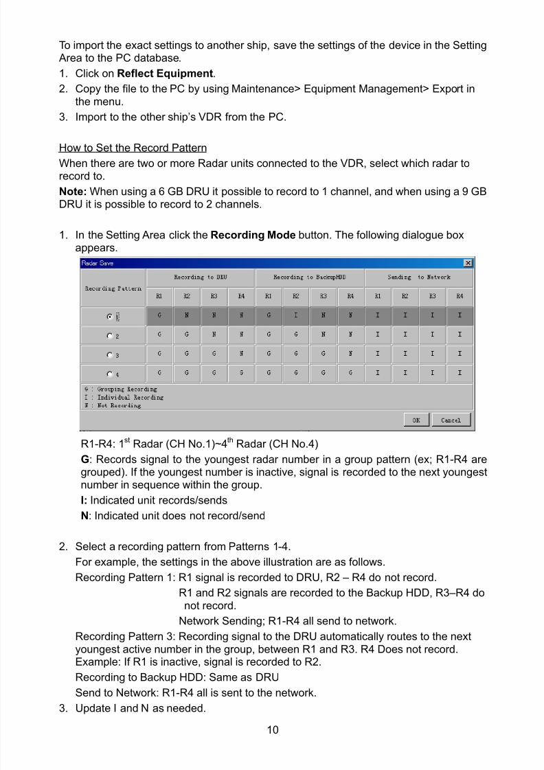
8102019 Ome44376d Vr3000 Mainte Cof26amp3bmol
httpslidepdfcomreaderfullome44376d-vr3000-mainte-cof26amp3bmol 1257
10
To import the exact settings to another ship save the settings of the device in the Setting Area to the PC database
1 Click on Reflect Equipment
2 Copy the file to the PC by using Maintenancegt Equipment Managementgt Export inthe menu
3 Import to the other shiprsquos VDR from the PC
How to Set the Record Pattern
When there are two or more Radar units connected to the VDR select which radar torecord to
Note When using a 6 GB DRU it possible to record to 1 channel and when using a 9 GBDRU it is possible to record to 2 channels
1 In the Setting Area click the Recording Mode button The following dialogue boxappears
R1-R4 1st Radar (CH No1)~4
th Radar (CH No4)
G Records signal to the youngest radar number in a group pattern (ex R1-R4 aregrouped) If the youngest number is inactive signal is recorded to the next youngestnumber in sequence within the group
I Indicated unit recordssends
N Indicated unit does not recordsend
2 Select a recording pattern from Patterns 1-4
For example the settings in the above illustration are as follows
Recording Pattern 1 R1 signal is recorded to DRU R2 ndash R4 do not record
R1 and R2 signals are recorded to the Backup HDD R3ndashR4 donot record
Network Sending R1-R4 all send to network
Recording Pattern 3 Recording signal to the DRU automatically routes to the nextyoungest active number in the group between R1 and R3 R4 Does not recordExample If R1 is inactive signal is recorded to R2
Recording to Backup HDD Same as DRU
Send to Network R1-R4 all is sent to the network
3 Update I and N as needed
8102019 Ome44376d Vr3000 Mainte Cof26amp3bmol
httpslidepdfcomreaderfullome44376d-vr3000-mainte-cof26amp3bmol 1357
11
Place the cursor above either I or N and left click to alternate With this I is set torecord while N is set to not record G cannot be changed
4 After completing setup click the OK button
5 To record settings to the database click Reflect Equipment in the Setting Area
How to Enter Information Manually
This VDR system receives in VESA (Video Electronics Standards Association) signal Image signal 05-1Vpp (When using composite signal the minimum synchronization
signal is 50 mV)
Horizontal Synchronization Signal Max plusmn91146 kHz
Vertical Synchronization Signal Max 35 Hz
Acceptable Image Resolution 640x480 ndash 1280x1024
Channel number conforms to the number displayed by the DCU
To set the Radar tab do the following
1 Click the Radar tab
2 Choose the channel with the entered Radar Image from the Information Area
3 Check the Active box in the Setting Area and enter the Horizontal and Verticalresolution of the incoming image in the Horizontal resolution and Vertical resolutioncolumns
4 Click the Set button
5 Click the Image Capturehellip button The Image Capture dialogue box appears
6 Click the Test button in the Image Capture window Radar image appears a fewseconds later
7 If the image is normal close the Image Capture window8 Input each item in the Setting Area
8102019 Ome44376d Vr3000 Mainte Cof26amp3bmol
httpslidepdfcomreaderfullome44376d-vr3000-mainte-cof26amp3bmol 1457
12
Items are as follows
Active Check a channel to activate it
Brand Enter brand nameType No Enter type noCheck Set and activate checkData Name Enter data nameHorizontal resolution Set horizontal resolutionVertical resolution Set vertical resolutionHorizontal Offset Move the picture horizontallyVertical offset Move the picture verticallyPLL This sets the frequency of the PLL-oscillatorCDEV Set CDEV
VCOSL Set VCO Signal LeadPhase (0-63) Phase setting selects the phase of the sampling clock relativeto phase locked loop signal in 64 steps of 5625 degrees IfPhase is not set correctly any section of an image consistingof vertical lines may show line ldquotearingrdquo
Sync Type Select the type of video sync signalHorizontal sync polarity Set the polarity of the horizontal sync signalVertical sync polarity Set the polarity of the vertical sync signalHDVD Sync Termination Sets horizontal and vertical synchronization point When
using a composite signal set to 75ohmsPulse Width for VD Detection (0-1020 Step4) Sets the pulse width for video signal
detectionInterlace Type When the video image is interlace set ldquoInterlaceldquo sampling
mode In Interlace mode the even pixels are sampled on oneframe and odd pixels are sampled on the other frame
8102019 Ome44376d Vr3000 Mainte Cof26amp3bmol
httpslidepdfcomreaderfullome44376d-vr3000-mainte-cof26amp3bmol 1557
13
Interlace Polarity Set interlace polarityITRP (0-4092 Step4) Enter interlace pulse positionITRW (0-4092 step4) Enter interlace pulse widthSampling Rate Display sampling rate Fixed at ldquo15 secondsrdquoCompress Type (viewer) Set compress type (viewer)Color Bit Display and set Color BitChange Pump Current Set pump current Fixed at ldquo05 mArdquo
Video Clock Polarity Set video clock polarity Fixed at ldquoThroughrdquoCounter Clock SelectionSelect counter clock selection Fixed at ldquo49 MHzrdquoVCO Clock Hold Sets VCO clock holdRed Gain (0-255) Enter red gainGreen Gain (0-255) Enter green gainBlue Gain (0-255) Enter blue gainRed Offset (0-255) Enter red offsetGreen Offset (0-255) Enter green offsetBlue Offset (0-255) Enter blue offsetBlack Level (0-255) Enter black levelEquipment Category Enter equipment category
Board Name Enter board name for corresponding channelNote Enter note
Note Offset Phase and Color Bit change with the length of the antenna cable
Marked Items For easy identification of input source enter Equipment Category Brand
Type No and Data Name
Measurement BoxThe Measurement Box is located on the left side of the Information Area The LOWHorizontal and Vertical counter should be higher than the HIGH counter If reversely the
HIGH counter is higher than the LOW counter it is possible that the SYNC Polaritysettings are adjusted incorrectly
8102019 Ome44376d Vr3000 Mainte Cof26amp3bmol
httpslidepdfcomreaderfullome44376d-vr3000-mainte-cof26amp3bmol 1657
14
Config Management
After all items have been set up proceed to the final setting management This can only
be executed one time after all tabs have been set up
1 Click on VDR Config Management in the Maintenance menu
2 Click on the Upload button to send all sent data to the VDR memory
3 Click each individual Write button to record to DRU Backup HDD and CF Note
If the settings are not uploaded to the VDR they have no effect on the unit
4 Click the Close button to close the VDR Config Management Dialogue Box
8102019 Ome44376d Vr3000 Mainte Cof26amp3bmol
httpslidepdfcomreaderfullome44376d-vr3000-mainte-cof26amp3bmol 1757
15
23 Serial Signal
The Serial tab sets the RS-422 signals received at the terminal board (SI01-SI08) and the
junction box (SI09-SI72) This channel is not only for NMEA but also binary and ASCII
data
Set the Serial tab as follows1 Click the Serial tab
2 Select a channel from the Information window
3 Click the Select Equipment button in the Setting Area
4 Choose the unit that is connected to the indicated Channel and click the OK Button
5 Adjust items as needed in the Setting Area
8102019 Ome44376d Vr3000 Mainte Cof26amp3bmol
httpslidepdfcomreaderfullome44376d-vr3000-mainte-cof26amp3bmol 1857
16
6 After finishing the settings for one channel click the Set buttonNote Be sure to do this before moving another channel
7 Repeat steps 2-6 to set up each channel
When running Config Management for Tab Settings
1 From the Maintenance menu click VDR Config Management and then Config
2 Click the Upload button to record data to the VDR memory3 Click the Write button to save data to the DRU backup HDD and CF
The buttons in the Setting Area are as followsSet Save edited dataCapture Received data shown in the serial window dialog boxSelect Equipment Select equipment settings (saved to the database) to reflect in
a channelReflect Equipment Save the equipment setting data to the databaseCheck Check all channels OK or NG (No Good) shown in
Information window
Individual Item ExplanationActive Put check in check box to make channel activeBrand Enter brand nameType No (Equipment Name) Set type no (equipment name)Check Do equipment checkData Name Enter data nameData Type Enter data typeBaud Rate Set baud rate (Available for SI01 to SI08)Data Bit Set number of bits (Available for SI01 to SI08)Parity Bit Set parity bit (Available for SI01 to SI08)Stop Bit Set stop bit (Available for SI01 to SI08)Source Checksum Enter checksum for GPS sourceTime out Set time outEquipment Category Set equipment categoryBoard Name Enter board names where channels are presentNote Enter note
Marked Items For easy identification of input source enter Equipment Category Brand
Type No Date and Name
8102019 Ome44376d Vr3000 Mainte Cof26amp3bmol
httpslidepdfcomreaderfullome44376d-vr3000-mainte-cof26amp3bmol 1957
17
24 Analog SignalAnalog signal is input via Junction Box IF-8530 (optional for VR-3000S)Receivable signal ndash10 to +10 V or 4 to 20mA
Connect the analog signal to V and G terminals on the Junction Box When 4 to 20 mAsignal is connected make a short circuit between the V and I input terminals with jumper
wireThe basic procedure for setting up the analog signal is as follows
1 Click the Analog tab
2 Select channel from the Information Area
3 Set detailed information of the selected channel in the Setting Area Refer to thefollowing illustration to enter detailed item information
In the factory settings there is no preset data when the Select Equipment button is
pressed In the case that the setup was completed on another ship and saved usingReflect Equipment import the data by clicking Select Equipment and choosing thesaved data
4 In the following order calibrate the Analog signal
① Click the Calibration button in the Setting Area
② Enter the voltage (or current) value for Calibration Point 1 and thecorresponding engineering value in the left and right boxes
③ Enter values for Calibration Point 2④ Enter unit for the values in Engineering Value Unit
8102019 Ome44376d Vr3000 Mainte Cof26amp3bmol
httpslidepdfcomreaderfullome44376d-vr3000-mainte-cof26amp3bmol 2057
18
In the above image the Engineering Value Unit is set to degrees (deg) TheCalibration Point 1 is -10V corresponding to 0 degrees Calibration Point 2 is10V corresponding to 30 degrees This is set corresponding to the connectedanalog sensor
When the Apply button is clicked the New Engineering Value of 29835Vcorresponding to the input Voltage of 989V is displayed in the bottom fieldWhenever the input value is changed this value also changes Check that theNew Engineering Value is within an appropriate range
Another method is to observe the Voltage (or Current) field in the top field andpress the Hold button of Point 1 when an appropriate value is displaying Dothis again for Point 2
⑤ Click the OK Button
5 When setting is complete click the Set button Be sure to do this before movinganother to channel
6 Repeat steps 1-5 to set up all channels
When using Config Manager with Tabs
1 From the Maintenance menu click VDR Config Management and then Config
2 Click the Upload button to record to VDR memory
3 Click the Write buttons to record to DRU Backup HDD and CF memory
The items in the Setting Area are as shown below Active Put check in check box to make channel activeBrand Enter brand name
Type No Set type no (equipment name)
Check Do equipment checkData Name Enter data nameData Type Analog Data type (0~10V -10~10v 4~20mV)
Sampling Rate Display sampling rateCalibration Active Disable and enable analog calibrationCalibration Point 1 Enter calibration point 1
Calibration Point 1 Value Enter calibration point 1 valueCalibration Point 2 Enter calibration point 2Calibration Point 2 Value Enter calibration point 2 valueEngineering Value Unit Enter engineering value unit
8102019 Ome44376d Vr3000 Mainte Cof26amp3bmol
httpslidepdfcomreaderfullome44376d-vr3000-mainte-cof26amp3bmol 2157
19
Note For -marked boxes values that are set at the Analog Calibration dialog box aredisplayed
Equipment Category Set equipment categoryBoard Name Enter board names where channels are presentNote Enter note
Marked Items For easy identification of input source enter Equipment CategoryBrand Type No Data and Name
25 Digital Signal
Digital signal is connected via Junction Box IF-8530 (optional for VR-3000S) The
receivable signal is 10-32 V for voltage signal or contact signal For voltage signal
connect to A and B input terminals on the Junction Box For contact signal connect to B
and G input terminals on the Junction Box Also make a short-circuit between the 24 and
A input terminals with a jumper wire
To set up the Digital tab
1 Click the Digital tab
2 Select a channel from the Information Area
3 Set up the digital signal from the Setting Area Refer to the following individual item
explanation
In the factory settings there is no preset data when the Select Equipment button is
pressed In the case that the setup was completed on another ship and saved using
Reflect Equipment import the data by clicking Select Equipment and choosing the
saved data
4 When setting Digital Signal to each 64 channel group perform the following
directions1 Click the Calibration button in the setting area
8102019 Ome44376d Vr3000 Mainte Cof26amp3bmol
httpslidepdfcomreaderfullome44376d-vr3000-mainte-cof26amp3bmol 2257
20
2 Check the active column of the channel group being set
3 Enter the status in columns 0 and 1 of that group
4 Click the OK Button
5 When finished setting up click the Set button
6 Repeat steps 2-5 to set up other channels
When using Config Manager with Tabs
1 From the Maintenance menu click VDR Config Management
2 Click the Upload button to record to VDR memory
3 Click the Write buttons to record to DRU Backup HDD and CF memory
The items in the Setting Area are as shown below
Active Put check in check box to make channel activeBrand Enter brand name
Type No Set type no (equipment name)Check Do equipment checkData Name Enter and display data nameContact Type Set contact type NO normal open NC normal closeSampling Rate Display sampling rateCalibration Active Disable and enable digital calibrationActive Status (1) Set status display when (1) is activeActive Status (0) Set status display when (0) is activeEquipment Category Set equipment categoryBoard Name Enter board names where channels are presentNote Enter note
Marked Items For easy identification of input source enter Equipment CategoryBrand Type No Date and Name
8102019 Ome44376d Vr3000 Mainte Cof26amp3bmol
httpslidepdfcomreaderfullome44376d-vr3000-mainte-cof26amp3bmol 2357
21
26 Audio
Microphone and VHF audio settings are performed in the Audio tab
Set the items in the Audio tab as shown below
1 Click the Audio tab
2 Select channel from the Information Area3 Click Select Equipment in the Setting Area
4 Click on the connected device in the indicated channel The setting contents aredisplayed in the Information and Setting Areas
5 If required update the item contents in the Setting Area Refer to the detailed itemexplanation below
6 After completing settings for a channel click the Set buttonNote Be sure to click the Set button before moving to another channel
7 Repeat steps 2-6 to set up other channels
8102019 Ome44376d Vr3000 Mainte Cof26amp3bmol
httpslidepdfcomreaderfullome44376d-vr3000-mainte-cof26amp3bmol 2457
22
When using Config Manager with tabs
1 From the Maintenance menu click VDR Config Management
2 Click the Upload button to record to VDR memory
3 Click the Write buttons to record to DRU Backup HDD and CF memory
MIC testDo the MIC test to check whether audio is received clearly in adequate level or not
1 Click the MIC TEST button in the Setting Area
2 Click the TEST button in the MIC Test dialogue box MIC test results are displayed in
the MIC Test dialogue box
3 Click the Close button to close the dialogue box
Note Not the same recordingplayback function as the previous Web Configuratorsoftware
Continuous MIC TestRun the continuous MIC test as needed accordingly
1 Click the Continuous MIC Test button in the Setting Area2 Set up how many times to perform in the Continuous MIC Test dialogue box and click
the Test button
3 Click the Close button to close the dialogue box
8102019 Ome44376d Vr3000 Mainte Cof26amp3bmol
httpslidepdfcomreaderfullome44376d-vr3000-mainte-cof26amp3bmol 2557
23
Active Put check in check box to make channel activeBrand Enter and display brand nameType No Set type no (equipment name)Check Do equipment checkData Name Enter data nameInput Type Enter input type Sampling Data Bit Displays sampling data bit rate
Sampling Frequency Displays Sampling FrequencyCodec Sets MIC typeMIC Test Active M1M3M5 Put a checkmark when performing MIC Test of M1M3M5MIS Test Active M2M4M6 Put a checkmark when performing MIC Test of M2M4M6 MIC M1M3M5 Position Enter MIC position of MIC M1M3M5MIC M2M4M6 Position Enter MIC position of MIC M2M4M6Threshold Level M1M3M5 Enter MIC test threshold level of MIC M1M3M5Threshold Level M2M4M6 Enter MIC test threshold level of MIC M2M4M6Equipment Category Set equipment categoryBoard Name Enter board names where channels are present
Note Enter note Marked Items For easy identification of input source enter Equipment Category BrandType No Date and Name
8102019 Ome44376d Vr3000 Mainte Cof26amp3bmol
httpslidepdfcomreaderfullome44376d-vr3000-mainte-cof26amp3bmol 2657
24
27 Alarm
Alarm and Alarm Status settings are found in the Alarm tab
The Alarm tab shows the following information about alarms Click the Time Categoryand Name tabs in the title bar to sort
Time Time of alarm
Category Alarm categoryName Name of alarm
Number Alarm number
Status Alarm status
Alarm Search
1 Click the Search button above the Alarm tab The Search dialogue box appears
2 Add a checkmark to any desired search items (multiple items can be selected)
Start Time Display name of alarms generated after a certain time
End Time Display name of alarms generated before a certain time
Name Display information for alarm name entered
8102019 Ome44376d Vr3000 Mainte Cof26amp3bmol
httpslidepdfcomreaderfullome44376d-vr3000-mainte-cof26amp3bmol 2757
25
Number Display information for alarm number entered
Status Display alarm status for alarm name entered
3 In the checked items column input the desired search items
4 Click the Search Button
Close the Search box to cancel a search
Note During a search the upper left Mode changes from Play to Search andDisplay search related information
8102019 Ome44376d Vr3000 Mainte Cof26amp3bmol
httpslidepdfcomreaderfullome44376d-vr3000-mainte-cof26amp3bmol 2857
26
28 Event
Click the items shown below to sort by item selected
Note You can sort the items in ascending order () descending order () and
initialization order (no symbol)
Time Time an event occurred
Category Category of an event
Name Name of an event
Contents1 Display data associated with log
Contents2 Display data associated with log
Event Search
Do the following to search events
1 Click the Search button on the upper right of the Event tab
2 In the dialogue box add a checkmark to desired search items Multiple items can bechecked
Start Time Display name of event generated after a certain time
End Time Display name of event generated before a certain time
Name Display event names entered
Number Display event numbers entered
Status Display event status entered
Enter information about the checked event to search in the character input box
3 Click the Search button
Note The mode changes from Play to Search when performing a search
8102019 Ome44376d Vr3000 Mainte Cof26amp3bmol
httpslidepdfcomreaderfullome44376d-vr3000-mainte-cof26amp3bmol 2957
27
29 Hardware
The Hardware tab provides information about the system hardware
The buttons in the Setting window work as follows
Self Check Status Display status of self check
CPU Display information about the CPU
Memory Size Display memory size
CPU Board Display status of CPU board
Audio Board Display status of Audio board
Serial Board Display status of Serial board
Radar Interface Board Display status of Radar Interface boardNote Enter and display note
Marked items are optional
8102019 Ome44376d Vr3000 Mainte Cof26amp3bmol
httpslidepdfcomreaderfullome44376d-vr3000-mainte-cof26amp3bmol 3057
28
210 JB
Connect the Junction Box to the DCU before turning on the system
The JB tab functions to set up the Junction Box
The basic procedure for setting up the Junction Box is as follows
1 Click the JB tab2 Select a Junction Box from the Information Area
3 Set up the Junction Box from the Setting Area
4 Click the Set button (Be sure to do this before moving to another channel)5 Click the Check button to perform an inspection on all channels In the Information
Area check column either OK or NG (No Good) is displayed
When using Config Manager with Tabs
1 From the Maintenance menu click VDR Config Management
2 Click the Upload button to record to VDR memory
3 Click the Write buttons to record to DRU Backup HDD and CF
The items in the Setting window work as followsActive Put check in check box to make channel activeNo Display Junction Box numberIP Address Display IP address of Junction Box acquired by VDRMAC Address Display MAC address of Junction Box acquired by VDRCheck Enable and disable equipment checkNote Enter note
Marked items are optional
8102019 Ome44376d Vr3000 Mainte Cof26amp3bmol
httpslidepdfcomreaderfullome44376d-vr3000-mainte-cof26amp3bmol 3157
29
211 Life Time
The Life Time tab controls consumable parts
The basic procedure for using the Life Time tab is as follows
1 Click the Life Time tab
2 Select a Type No in the Information Area3 Set up the chosen part from Setting Area
4 Click the Set button
Note Be sure to click the Set button before moving to set up a different Type
The items in the Setting window work as follows
Type No Enter and display type no
Data Name Enter and display data name
Level Set replacement level Legal Exchange Parts or Normal Exchange Parts
Replace Date Enter and display recommended day of replacement
Lifetime Term Not usedNote Enter and display note
The Status column of the Information Area displays as follows
OK The recommended date of replacement shown in the Replace Date
box in the Information window has not passed
Out of Date The date of replacement has passed
None The date of replacement has not been set
8102019 Ome44376d Vr3000 Mainte Cof26amp3bmol
httpslidepdfcomreaderfullome44376d-vr3000-mainte-cof26amp3bmol 3257
30
212 Network
The Network tab sets the system network
The basic procedure for setting up the system network is as follows
1 Click the Network tab
2 Select a port from the Information Area
3 Set up the network from the Setting Area
4 Click the Set button
Note1 Be sure to click the Set button before moving to set up a different Port
Note2 After setting the system network reboot the VDR to apply the settings
The items in the Setting window work as follows
LAN Type Enter LAN type Public LAN or JB LAN
MAC Address Enter MAC address
IP Address Enter IP address
Subnet Mask Enter subnet mask
Gateway Address Enter gateway address
Live Play Multicast Mode (Only JB LAN) Check box to enable live player multicast
mode
Multicast Address (Only Public LAN) Enter and display live player multicast addressNote Enter note
Marked items are optional
8102019 Ome44376d Vr3000 Mainte Cof26amp3bmol
httpslidepdfcomreaderfullome44376d-vr3000-mainte-cof26amp3bmol 3357
31
213 System
The System tab sets system related functions
The basic procedure for using the System tab is as follows
1 Click the System tab
2 Set up the chosen item from the Setting Area
3 Click the Set button
Note Be sure to click the Set button before moving to a different tab
The items in the Setting window work as follows
VDR Type Enter type of VDR
VDR Model Enter model number of VDR
Radar Interface Check Enable and disable checking of the Radar Interface board
Junction Box Count Enter number of junction boxes in system
DRU Flash Count Enter number of DRU flash disks in system Set 1 when DRU
serial no is 5000 and more Set 3 when DRU serial no is less
than 5000
DRU Capacity Display capacity of DRU
Backup HDD Capacity Display capacity of Backup HDD
VDR Config Version Display version no of VDR
VDR Config Date Display the number of hours the VDR settings have
been saved
VDR Config Code Display configuration identity code
Installation Engineer Enter name of the equipment installer
Installation Company Enter name of installers company
8102019 Ome44376d Vr3000 Mainte Cof26amp3bmol
httpslidepdfcomreaderfullome44376d-vr3000-mainte-cof26amp3bmol 3457
32
Installation Date Enter the date of the installation
MIC Test Time Enter the date of the MIC test
Note Enter note Marked items are optional
USB memory logging Do not check Enable
IEEE1394 BUS Error Auto Restart function Not used
IEEE1394 Active Node Count Do not change the default value of 3 (However set to 5
for serial number 5000 or less of DRU)
IEEE1394 Recover Process Limit Count Do not change the default value of 10
DRU Error Auto Restart function Not used
REBOOT DELAY TIME (sec) Do not change the default value of 10
LIMIT REBOOT COUNT Do not change the default value of 10
Live Player Max Connection Count The max number of Live Player V4 that can be
connected simultaneously The default no is two
but a maximum of five can be set here After you
change this option reboot the VDR to apply the
setting Disconnect the cable connected with
Live Player V4 (PC) from the VDR and thenreconnect it
214 Software
The Software tab sets and display software-related operations
The basic procedure for using the Software tab is as follows
1 Click the Software tab
2 Set up the chosen Item from the Setting Area
3 Click the Set button
8102019 Ome44376d Vr3000 Mainte Cof26amp3bmol
httpslidepdfcomreaderfullome44376d-vr3000-mainte-cof26amp3bmol 3557
33
The items in the Setting window work as follows
VDR System Program Display the VDR system program no
Process Version Display the process version
Power Distribution Unit (PDU) Display the version no of the PDU
Operation System Display the version no of the OS
Audio Driver Display the version no of the audio driverRAP Version Enter the version no of the RAP
AP Version Enter the version no of the AP
JB1-8 Boot Program Display the no of the RJB Boot program for Junction Boxes
1 to 8
JB1-8 App Program Display the no of the RJB App program for Junction Boxes
1 to 8
Watch Dog Interval Do not change the default value of 60 (Enter the process
response time A process is repeated if there is no response
within the time interval set here)
Giveup Interval Do not change the default value of 300 (Enter the restart
watch time The restarting of a process is stopped when the
number of times it has been restarted is exceeded within the
interval set here)
Refork Limit Do not change the default value of 10 (Enter the upper limit
for process restart The restarting of a process is stopped
when the number of times it has been restarted exceeds the
Give up Interval)
Note Enter note
Marked Items are optional
8102019 Ome44376d Vr3000 Mainte Cof26amp3bmol
httpslidepdfcomreaderfullome44376d-vr3000-mainte-cof26amp3bmol 3657
34
215 GPS
The GPS tab sets GPS-related parameters
The basic procedure for using the GPS tab is as follows
1 Click the GPS tab
2 Set up the chosen channel from the Information window3 Set up the chosen item in the Setting Area
4 Click the Set button
5 Repeat steps 2-4 to set up each Channel
6 Click the Check button to perform an inspection on all channels In the Information Area check column either OK or NG (No Good) is displayed
The items in the Setting window work as follows
Priority Display priority order
Date and Time SourceShip Position Source Set GPS source channel (serial channel
number for ZDA sentence)
Check Enable and disable checking
GPS Antenna Position From Bow Enter position of GPS antenna from bow
GPS Antenna Position From Stern Enter position of GPS antenna from stern
GPS Antenna Position From Port Enter position of GPS antenna from port
GPS Antenna Position From Starboard Enter position of GPS antenna from starboard
GPS Failure Threshold If the ZDA is input within the set time limit
the system restarts synchronized If not
input within the time limit the system restarts
without synchronization
8102019 Ome44376d Vr3000 Mainte Cof26amp3bmol
httpslidepdfcomreaderfullome44376d-vr3000-mainte-cof26amp3bmol 3757
35
GPS Delay Time by Time Sync Enter minimum time delay for time
synchronization Time synchronization is started
only in the time set here
GPS Difference Interval The time set here is added to the GPS time to
synchronize the system time Leave at the default
0 value setting
GPS Sync Giveup Time If the system receives the GPS time within the
time set the system synchronizes with the time
When not receiving a signal the system displays
an ldquoerror 26rdquo message
ZDA Timeout Enter value (seconds) for ZDA timeout (234 error)
from GPS
Note Enter and display note
Marked Items are optional
216 VesselThe Vessel tab sets and displays own ships information such as name and IMO number
The basic procedure for using the Vessel tab is as follows
1 Click the Vessel tab
2 Set up information in the Setting window
3 Click the Set button (Be sure to do this before moving to another port)
4 From the Maintenance menu click VDR Config Management and then Config5 Click the Write buttons to save data to the DRU backup HDD CF
The buttons in the Setting window works as follows
Vessel Name Enter name of vessel
Vessel IMO Number Enter IMO number of vessel
Vessel Flag Enter flag of vessel
Approval of Authority Enter name of approving authority
Note Enter note
Marked items are optional
8102019 Ome44376d Vr3000 Mainte Cof26amp3bmol
httpslidepdfcomreaderfullome44376d-vr3000-mainte-cof26amp3bmol 3857
36
217 Delivery
The Delivery tab functions to transmit data from the VDR to a PC via Ethernet LAN Do
not use this function during live connection
The basic procedure for using the Delivery tab is as follows
1 Click the Delivery tab
2 Click the Add button to show the Delivery Config window
3 Select protocol from the Protocol drop-down box (Unicast or Multicast)
4 Enter IP address in the IP address input box
5 Enter port number in the port number input box
6 Click the tab of the data to send (Analog Digital or Serial)
7 Select the channel of the data to send
8 If Serial was selected at step 6 select applicable data sentence from the Inactivewindow Click the right arrow to move the data sentence to the Active window
9 Click the OK button to close the Delivery Config window
10 The settings are listed in a table in the Delivery window Check the checkbox in the
Active column and then click the Set button
The buttons in the Setting window works as follows
Set Save edited settings
Add Create new delivery settings
Modify Modify selected delivery settings
Delete Delete selected delivery settings
8102019 Ome44376d Vr3000 Mainte Cof26amp3bmol
httpslidepdfcomreaderfullome44376d-vr3000-mainte-cof26amp3bmol 3957
37
3 How to Back up Configuration DataThis chapter shows how to back up configuration data to various storage media
Configuration data can be opened with Word Pad or any text editor other than Notepad
31 How to Back up Configuration Data to the Startup CompactFlash (CF)
Back up data to the startup CF after setting the VDR Configuration data is created on the
CF as a configini file
Note When the error shown below occurs during the downloading or uploading of
configuration data check the connection of the DRU Backup HDD and CF and then
upload or download the configuration data again
[CONN] Download failed
[CONN] Could not upload config file
If error occurs again re-install the VDR Maintenance Viewer
Do the following to back up data to a CF
1 Set up parameters on the tabs referring to Chapter 2
2 Click the Maintenance menu
3 Select VDR Config Management
4 Click the Upload button
5 A confirmation box appears click the OK button to start uploading to the VDR
6 Click the Write button where the arrow connects between VDR and DRU BackupHDD
7 A confirmation window appears click the OK button to save the configuration data tothe DRU and Backup HDD
8102019 Ome44376d Vr3000 Mainte Cof26amp3bmol
httpslidepdfcomreaderfullome44376d-vr3000-mainte-cof26amp3bmol 4057
38
8 Click the Write button where the arrow connects between the VDR and CF
9 A confirmation window appears click the OK button to save the configuration data tothe startup CF
10 Check that the PC VDR DRU Backup HDD and CF share the same VDR configcode
32 How to Back up Configuration Data to a PC
Configuration data saved to the PC can be edited with Wordpad and shared with other
vessels For future service ease it is recommended to backup configuration data to the
PC and have the data on board the vessel Also it is recommended to upload this data to
Furuno SMS (Service Management System) If unable to upload to Furuno SMS please
contact the Service Center Furuno Japan
To back up configuration data to the PC do as follows
1 Set up parameters on the tabs referring to Chapter 2
2 Click the Maintenance menu
3 Select VDR Config Management
4 Click the Export to button
5 A confirmation window appears click the OK button
6 Select where to save the data enter file name then click the Open button
7 Confirm that back up file is in the location selected
33 How to restore the default settings
Click the Default button on the VDR Config Management window to restore the default
settings of the DRU Backup HDD CF and VDR Maintenance Viewer
8102019 Ome44376d Vr3000 Mainte Cof26amp3bmol
httpslidepdfcomreaderfullome44376d-vr3000-mainte-cof26amp3bmol 4157
39
4 How to Upload Configuration Datafrom a PCThe procedure below shows how to upload configuration from the PC to aVR-3000VR-3000S
1 Click the Maintenance menu
2 Select VDR Config Management
3 Click the Import from button
4 The Open window appears Select configuration data and then click the Open button
5 Click the Upload button to upload data to the VR-3000VR-3000S
6 Click the Write buttons to save data to the DRU backup HDD and CF
8102019 Ome44376d Vr3000 Mainte Cof26amp3bmol
httpslidepdfcomreaderfullome44376d-vr3000-mainte-cof26amp3bmol 4257
40
5 Media ManagementThe media management feature deletes data from recording media initialization the
system etc There are two method LAN connection and Direct connection The Direct
connection takes longer time than the LAN connection Basically use the LAN connection
method
Note Initialization or creation of recording media is not available when Source Select onthe Live Player V4 is selected to Backup HDD
51 Initialization
This section shows how to delete data from the recording media Configuration data is
not deleted After performing the software configuration delete the data from the DRU
and HDD
Do the following to delete data from the DRU (LAN connection)
1 Set the PlaybackCPU switch in the DCU to the CPU position
2 Use an Ethernet cross cable to connect the PC to J14 (DATA) in the DCU (See page5)
3 Open the Tool menu
4 Select Media Management to open the VDR Media Management window
5 Check that IP address shown in the ldquoLAN Connect to IPrdquo in VDR Media Table Area isthe same as the IP address access point
6 Select ldquoLAN Connect to IPrdquo in the VDR Media Table column
8102019 Ome44376d Vr3000 Mainte Cof26amp3bmol
httpslidepdfcomreaderfullome44376d-vr3000-mainte-cof26amp3bmol 4357
41
7 Click the Analyze button A list of recording media connected to the VDR appears
Put a checkmark in the checkbox of the Select column for the DRU in the Name columnNote If there are several flash memories in the DRU all flash memories are shownCheck all flash memories shown
8 Select ldquoDRU Initializerdquo from the Operation dropdown list in the Operation area
10 Click the Run button
Do the following to delete data from the DRU (Direct connection)
1 Start Live Player V4 software
2 Open the Tool menu and select Source Select Select Live from the pull-downmenu
3 Click the Alarm tab and open Alarm History
4 Set the PlaybackCPU switch in the DCU to the Playback position
5 Wait approx 10 minutes and confirm that Alarm 174 occurs on Alarm History of LivePlayer V4
6 Connect an IEEEE1394 cable between J6 in the DCU and the PC
7 Open the Tool menu
8 Select Media Management to show the VDR Media Management window
9 Select Direct in the VDR Media Table column
10 Click the Analyze button A list of recording media connected to the VDR appears
11 Put a checkmark in the checkbox of the Select column for the DRU in the Namecolumn
Note If there are several flash memories in the DRU all flash memories are shownCheck all flash memories shown
12 Select ldquoDRU Initializerdquo from the Operation dropdown list in the Operation area
13 Enter password in the password column
14 Click the RUN button
8102019 Ome44376d Vr3000 Mainte Cof26amp3bmol
httpslidepdfcomreaderfullome44376d-vr3000-mainte-cof26amp3bmol 4457
42
Delete data from the Backup HDD as follows (LAN connection)
1 Set the PlaybackCPU switch in the DCU to the CPU position
2 Check that an Ethernet cross cable is connected between J14 in the DCU and the PC
3 Open the Tool menu
4 Select Media Management to open the VDR Media Management window
5 Check that IP address shown in the LAN Connect to IP in VDR Media Table Area is
the same as the IP address access point6 Select LAN Connect to IP in the VDR Media Table column
7 Click the Analyze button
8 A list of recording media connected to the VDR appears
9 Put a checkmark in the box of the Select column for the Backup HDD in the Namecolumn Select ldquoBackup HDD Initializerdquo from the Operation dropdown list in theOperation area
10 Click the Run button
Delete data from the Backup HDD as follows (Direct connection)
1 Start Live Player V4 software
2 Open the Tool menu and select Source Select Select Live from the pull-downmenu
3 Click the Alarm tab and open Alarm History
4 Set the PlaybackCPU switch in the DCU to the Playback position
5 Wait approx 10 minutes and confirm that Alarm 174 occurs on Alarm History of LivePlayer V4
6 Connect an IEEE1394 cable between J6 in the DCU and the PC
7 Open the Tool menu
8 Select Media Management to open the VDR Media Management window9 Select Direct in the VDR Media Table window
10 Click the Analyze button A list of recording media connected to the VDR appears
11 Put a checkmark in the check box of the Select column for the Backup HDD in theName column Select ldquoBackup HDD Initializerdquo from the Operation dropdown list in theOperation area
12 Enter password
13 Click the Run button
8102019 Ome44376d Vr3000 Mainte Cof26amp3bmol
httpslidepdfcomreaderfullome44376d-vr3000-mainte-cof26amp3bmol 4557
43
52 CreationThe Creation feature initializes recording media
Note1 This feature deletes ALL configuration data Backup all VDR configuration data
Note2 When you initialize medium that is a different format for the DRU or Backup HDDdelete all partitions with the disk management tool of Windows
Note3 When the Creation is failed try again If you can not initialize recording media tryunder condition as shown below
Do the Creation by the direct connection (When the Creation by the LAN
connection is failed)
Delete all partitions of the DRU or Backup HDD with the disk management tool of
Windows to do the Creation
If the Creation is still failed request service to repairreplace the DRU or Backup
HDD
Initialize the DRU as follows (LAN connection)
1 Set the PlaybackCPU switch in the DCU to the CPU position
2 Check that an Ethernet cross cable is connected between J14 in the DCU and the PC
3 Open the Tool menu
4 Select Media Management to open the VDR Media Management window
5 Check that IP address shown in the LAN Connect to IP in VDR Media Table Area isthe same as the IP address access point
6 Check ldquoLAN Connect to IPrdquo in the VDR Media Table column
7 Click the Analyze button A list of recording media connected to the VDR appears
8 Put a checkmark in the box of the Select column for the DRU in the Name column
Select ldquoDRU Creationrdquo from the Operation dropdown list in the Operation area
9 Click the Run button
Initialize the Backup HDD as follows (LAN connection)
1 To format the Backup HDD place a checkmark in the Select column of the listedrecord media in the Name column of the VDR Media Management dialogue box
2 From the Operation drop down list of the Operation area select ldquoBackup HDDCreation (Radar) or ldquoBackup HDD Creationrdquo
Two partition tools are available for the Backup HDD in the Media Management as
below
Backup HDD creation
This tool is used when the number of the SXGA video signal connected to the BackupHDD is the same as the DRU The same partition is created on both DRU and HDD
(1) When two SXGA video signals are recorded onto the HDD while 9-GB DRU isconnected
(2) When an SXGA video signal is recorded onto the HDD while 6-GB DRU isconnected
Backup HDD creation (radar)
This tool is used when two SXGA video signals are recorded onto the HDD with 6-GB
DRU connected The HDD has an area (radar) to record the second radar signal inaddition to the same partition as the DRU This tool cannot be used when 9-GB DRUis connected
3 Press the Run Button
8102019 Ome44376d Vr3000 Mainte Cof26amp3bmol
httpslidepdfcomreaderfullome44376d-vr3000-mainte-cof26amp3bmol 4657
44
Initialize the DRU as follows (Direct connection)
1 Start Live Player V4 software
2 Open the Tool menu and select Source Select Select Live from the pull-downmenu
3 Click the Alarm tab and open Alarm History
4 Set the PlaybackCPU switch in the DCU to the Playback position
5 Wait approx 10 minutes and confirm that Alarm 174 occurs on Alarm History of LivePlayer V4
6 Connect an IEEE1394 cable between J6 in the DCU and the PC
7 Open the Tool menu
8 Select Media Management to open the VDR Media Management window
9 Select Direct in the VDR Media Table window
10 Click the Analyze button A list of recording media connected to the VDR appears
11 Put a checkmark in the box of the Select column for the DRU and the desiredrecording media in the Name column In the Operation dropdown list of the Operationarea select ldquoDRU Creationrdquo
12 Enter password in the password column
13 Click the Run button
Initialize the Backup HDD as follows (Direct Connection)
1 To format the Backup HDD place a checkmark in the Select column of the listedrecord media in the Name column of the VDR Media Management dialogue box
2 From the Operation column of the Operation area select ldquoBackup HDD Creation(Radar) or ldquoBackup HDD Creationrdquo
Backup HDD creation
This tool is used when the number of the SXGA video signal connected to the BackupHDD is the same as the DRU The same partition is created on both DRU and HDD
(1) When two SXGA video signals are recorded onto the HDD while 9-GB DRU is
connected
(2) When an SXGA video signal is recorded onto the HDD while 6-GB DRU is
connected
Backup HDD creation (radar)
This tool is used when two SXGA video signals are recorded onto the HDD with 6-GBDRU connected The HDD has an area (radar) to record the second radar signal inaddition to the same partition as the DRU This tool cannot be used when 9-GB DRUis connected
3 Enter the password in the Password column
4 Press the Run Button
8102019 Ome44376d Vr3000 Mainte Cof26amp3bmol
httpslidepdfcomreaderfullome44376d-vr3000-mainte-cof26amp3bmol 4757
45
53 How to Enable Recording Area on the Backup HDD
This function enables writing over a recording area To prevent falsification of data all
recording areas must be saved otherwise this function is disabled To use this function push
the SAVE button Save the data before doing this procedure
Note Software version 135 or higher can enable writing over a recording area even if
all recording areas are not saved
Recording enable (LAN connection)
1 Set the PlaybackCPU switch in the DCU to the CPU position
2 Check that an Ethernet cross cable is connected between J14 in the DCU and the PC
3 Open the Tool menu
4 Select Media Management to open the VDR Media Management window
5 Check that IP address shown in the ldquoLAN Connect to IPrdquo in VDR Media Table Area isthe same as the IP address access point
6 Select ldquoLAN Connect to IPrdquo in the VDR Media Table column7 Click the Analyze button A list of recording media connected to the VDR appears
8 Put a checkmark in the box of the Select column for the Backup HDD in the Namecolumn
9 Select ldquoBackup HDD Recording Area Enablerdquo from the Operation dropdown list in theOperation area
10 Click the Run button
Recording enable (Direct connection)
1 Start Live Player V4 software
2 Open the Tool menu and select Source Select Select Live from the pull-down menu3 Click the Alarm tab and open Alarm History
4 Set the PlaybackCPU switch in the DCU to the Playback position
5 Wait approx 10 minutes and confirm that Alarm 174 occurs on Alarm History of LivePlayer V4
6 Connect an IEEE1394 cable between J6 in the DCU and the PC
7 Open the Tool menu
8 Select Media Management to open the VDR Media Management window
9 Select Direct in the VDR Media Table window
10 Click the Analyze button A list of recording media connected to the VDR appears11 Put a checkmark in the box of the Select column for the Backup HDD in the Name
column
12 Select ldquoBackup HDD Recording Area Enablerdquo from the Operation dropdown list in theOperation area
13 Enter password
14 Click the Run button
8102019 Ome44376d Vr3000 Mainte Cof26amp3bmol
httpslidepdfcomreaderfullome44376d-vr3000-mainte-cof26amp3bmol 4857
46
6 Other Functions
61 Software Management
The software download feature downloads VDR system software to the PC
To download software
1 Click the Maintenance menu
2 From the Software Management menu click Software Download to show theSoftware Download window
3 Enter the IP address 1000100 in the IP address box in the Update Server area
4 Click the Download Software button
5 The confirmation window appears click the OK button
The Software Backup Execute window shows the results of the download
Software is downloaded to C Program Files VDR Viewer Viewer Backup The software file
name is vdrtar
To Update Software
VDR system program version 16x can update the software with the procedure shownbelow
Note Do not update the file downloaded in procedures above
1 Click the Maintenance menu
2 From the Software Management menu click Software Upload to show the SoftwareUpload area
3 Click the Select button to show the Open window
4 Select update file (vdrtar) and click the Open button
8102019 Ome44376d Vr3000 Mainte Cof26amp3bmol
httpslidepdfcomreaderfullome44376d-vr3000-mainte-cof26amp3bmol 4957
47
5 Check the displayed Software information is correct
6 Enter the IP address 1000100 in the IP address box in the Update Server area
7 Enter password
8 Click the Update button
After the updating is completed the VDR is automatically restarted
Note Click the Restore button on the Software Update window to restore previoussoftware version This feature is available after updating the software
62 Password Management
The password can be changed for a serviceman to access the equipment Contact
FURUNO to get the default password to use during installation
Serviceman password
1 Click the Maintenance menu2 Select Change Serviceman Password from Password Management to show the
Change Serviceman Password window
3 Enter current password in the Old Password box
4 Enter the new password in the New Password box of the Change Password area
5 Enter new password again in the Confirm New Password box
6 Click the OK button
Audio password
The audio password set at the VDR Maintenance Viewer can be removed to enable
audio access without password1 Click the Maintenance menu
2 Select Change Audio Password from Password Management to show the Change Audio Password window
3 The confirmation window appears click the OK button
8102019 Ome44376d Vr3000 Mainte Cof26amp3bmol
httpslidepdfcomreaderfullome44376d-vr3000-mainte-cof26amp3bmol 5057
48
63 Record ComparisonThe integrity of the DRU and Backup HDD recordings can be compared This function isused by the RampD engineer for debugging
Follow the procedure as shown below
1 Click the Maintenance menu2 Select Record Comparison to show the Record Comparison window
The results are shown every 15 seconds in the Record Comparison window
8102019 Ome44376d Vr3000 Mainte Cof26amp3bmol
httpslidepdfcomreaderfullome44376d-vr3000-mainte-cof26amp3bmol 5157
49
64 Software History
This section shows you to save and configure software history (communications record)
How to save software history
Note When the error dialog appears while saving the software history restart the VDR
Maintenance Viewer
1 Click the Maintenance menu
2 Select Software History Collect
3 Click the Select button The Open dialog box appears
4 Select where to save the data then click the Open button
5 Select desired save condition then click the OK buttonNone No savingAt Once Save the software history manually Saving begins as soon as the OK button is clickedPeriodic For debugging Do not use otherwise The intervals are 30 sec 60 secand 120 secAlarm Detection For debugging Do not use otherwise Software history is savedwhen specified alarm is released Enter alarm number
How to configure software communications record
The RampD engineer uses this function for debugging Do not do this procedure unless
required Malfunction can result
1 Click the Maintenance menu
2 Select Software History Config
3 Do the followingProcess Select the type of communications record to save ALL saves allcommunications records
Detail Hide or show detailed information4 Click the Send button
8102019 Ome44376d Vr3000 Mainte Cof26amp3bmol
httpslidepdfcomreaderfullome44376d-vr3000-mainte-cof26amp3bmol 5257
50
65 Easy SetupThis feature sets equipment settings in batch and creates a data file of those settings
Default template The default template is created with the settings entered at installation
1 Click the Maintenance menu
2 Select Easy Setup to show the Template Selection window
3 Select Default Template
4 Click the Start button to show the Easy Setup window
5 Right click the channels (Radar Audio Digital Serial Analog) then select Edit toshow the Equipment Selection window
6 From the Equipment Directory window select equipment connected to the selectedchannel and then click the OK button
7 Repeat steps 5 and 6 to select equipment settings for each channel
8 Click the Save button in the Easy Setup window to show the Save window
9 Select where to save the file and enter file name
10 Click the Save button
8102019 Ome44376d Vr3000 Mainte Cof26amp3bmol
httpslidepdfcomreaderfullome44376d-vr3000-mainte-cof26amp3bmol 5357
51
Specific template Use a file already created
1 Click the Maintenance menu
2 Select Easy Setup to show the Template Selection window
3 Check Specified Template
4 Click the Select button and then select the file to edit
5 Click the Start button to show the Easy Setup window
6 Right click the channels (Radar Audio Digital Serial Analog) then select Edit toshow the Equipment Selection window
7 From the Equipment Directory window select equipment connected to the selectedchannel and then click the OK button
8 Repeat steps 6 and 7 to select equipment settings for each channel
9 Click the Save button in the Easy Setup window to show the Save window
10Select where to save the file and enter file name
11 Click the Save button
66 Equipment Management
This feature controls the import and export of equipment settings
Import data file
Import data files of equipment settings created in Easy Setup etc to the VDR
1 Click the Maintenance menu
2 Select Import from Equipment Management to show the Open window
3 Select the data file to import and click Open
Export data file
Export data files of equipment settings from the VDR to a PC
1 Click the Maintenance menu
2 Select Export from Equipment Management to show the Save window
3 Enter file name
4 Click the Save button
8102019 Ome44376d Vr3000 Mainte Cof26amp3bmol
httpslidepdfcomreaderfullome44376d-vr3000-mainte-cof26amp3bmol 5457
52
67 PC_RAP
This feature enables the same operation of the RAP (Remote Alarm Panel) from a PC
Select PC_RAP from the Tool menu to show the PC_RAP window
The buttons in the PC_RAP window function as shown below
SAVE Stop recording in the area where recording is currently being done
ACK Silence audio alarm
The PC_RAP display shows the following information with LEDs
RAP_LEDs Display the status of LEDs on the RAPSave The Save button blinks yellow when pushed When the 4 memory
areas have data recorded to them the Save button lights orange when
pushed
Normal Lights (green) where there are no unconfirmed or not restored
alarms
Error Flashes (red) for not confirmed alarm Lights (red) for unrestored
alarm
8102019 Ome44376d Vr3000 Mainte Cof26amp3bmol
httpslidepdfcomreaderfullome44376d-vr3000-mainte-cof26amp3bmol 5557
53
Backup HDD Information Display status of backup HDD
Selected Display current recording area and its status in green for
normal operation and in red for abnormal operation
Size Display capacity of backup HDD
Alarm area displays unconfirmed alarms
Time Display time alarm was generatedNumber Display number of alarm
Name Display name of alarm
Pending Alarm displays the unrestored alarms out of confirmed alarms only
Time Display time alarm was generated
Number Display number of alarm
Name Display name of alarm
8102019 Ome44376d Vr3000 Mainte Cof26amp3bmol
httpslidepdfcomreaderfullome44376d-vr3000-mainte-cof26amp3bmol 5657
54
68 Other
Status Monitor
The status monitor feature provides comprehensive data about the status of the VDR
From the menu bar click Toolgt Status Monitor to show the Status Monitor window
The buttons in the Status Monitor window work as shown below
Reload Settings for automatic refreshing of the status monitor
ON Turn automatic refresh OFF
OFF The Status Monitor is refreshed every five seconds
Save Available when Reload ON is selected The contents of the Status Monitor can be
saved to a text fileUpdate Update the Status Monitor display
Close Close the Status Monitor display
8102019 Ome44376d Vr3000 Mainte Cof26amp3bmol
httpslidepdfcomreaderfullome44376d-vr3000-mainte-cof26amp3bmol 5757
VDR Error List
This feature compiles all the errors shown on the RAP for easy reference
Access from MenugtToolgtVDR Error List
The VDR error list contains the following information
NO Display the number of the error
Title Display the name of the error
Detail Display details about the error
Exchange Check
This feature removes the alarms generated when replacing the DRU or backup HDD
Access MenugtToolgtExchange Check select either DRU or Backup HDD and click OK
Reboot
Reboot the VDR
8102019 Ome44376d Vr3000 Mainte Cof26amp3bmol
httpslidepdfcomreaderfullome44376d-vr3000-mainte-cof26amp3bmol 1357
11
Place the cursor above either I or N and left click to alternate With this I is set torecord while N is set to not record G cannot be changed
4 After completing setup click the OK button
5 To record settings to the database click Reflect Equipment in the Setting Area
How to Enter Information Manually
This VDR system receives in VESA (Video Electronics Standards Association) signal Image signal 05-1Vpp (When using composite signal the minimum synchronization
signal is 50 mV)
Horizontal Synchronization Signal Max plusmn91146 kHz
Vertical Synchronization Signal Max 35 Hz
Acceptable Image Resolution 640x480 ndash 1280x1024
Channel number conforms to the number displayed by the DCU
To set the Radar tab do the following
1 Click the Radar tab
2 Choose the channel with the entered Radar Image from the Information Area
3 Check the Active box in the Setting Area and enter the Horizontal and Verticalresolution of the incoming image in the Horizontal resolution and Vertical resolutioncolumns
4 Click the Set button
5 Click the Image Capturehellip button The Image Capture dialogue box appears
6 Click the Test button in the Image Capture window Radar image appears a fewseconds later
7 If the image is normal close the Image Capture window8 Input each item in the Setting Area
8102019 Ome44376d Vr3000 Mainte Cof26amp3bmol
httpslidepdfcomreaderfullome44376d-vr3000-mainte-cof26amp3bmol 1457
12
Items are as follows
Active Check a channel to activate it
Brand Enter brand nameType No Enter type noCheck Set and activate checkData Name Enter data nameHorizontal resolution Set horizontal resolutionVertical resolution Set vertical resolutionHorizontal Offset Move the picture horizontallyVertical offset Move the picture verticallyPLL This sets the frequency of the PLL-oscillatorCDEV Set CDEV
VCOSL Set VCO Signal LeadPhase (0-63) Phase setting selects the phase of the sampling clock relativeto phase locked loop signal in 64 steps of 5625 degrees IfPhase is not set correctly any section of an image consistingof vertical lines may show line ldquotearingrdquo
Sync Type Select the type of video sync signalHorizontal sync polarity Set the polarity of the horizontal sync signalVertical sync polarity Set the polarity of the vertical sync signalHDVD Sync Termination Sets horizontal and vertical synchronization point When
using a composite signal set to 75ohmsPulse Width for VD Detection (0-1020 Step4) Sets the pulse width for video signal
detectionInterlace Type When the video image is interlace set ldquoInterlaceldquo sampling
mode In Interlace mode the even pixels are sampled on oneframe and odd pixels are sampled on the other frame
8102019 Ome44376d Vr3000 Mainte Cof26amp3bmol
httpslidepdfcomreaderfullome44376d-vr3000-mainte-cof26amp3bmol 1557
13
Interlace Polarity Set interlace polarityITRP (0-4092 Step4) Enter interlace pulse positionITRW (0-4092 step4) Enter interlace pulse widthSampling Rate Display sampling rate Fixed at ldquo15 secondsrdquoCompress Type (viewer) Set compress type (viewer)Color Bit Display and set Color BitChange Pump Current Set pump current Fixed at ldquo05 mArdquo
Video Clock Polarity Set video clock polarity Fixed at ldquoThroughrdquoCounter Clock SelectionSelect counter clock selection Fixed at ldquo49 MHzrdquoVCO Clock Hold Sets VCO clock holdRed Gain (0-255) Enter red gainGreen Gain (0-255) Enter green gainBlue Gain (0-255) Enter blue gainRed Offset (0-255) Enter red offsetGreen Offset (0-255) Enter green offsetBlue Offset (0-255) Enter blue offsetBlack Level (0-255) Enter black levelEquipment Category Enter equipment category
Board Name Enter board name for corresponding channelNote Enter note
Note Offset Phase and Color Bit change with the length of the antenna cable
Marked Items For easy identification of input source enter Equipment Category Brand
Type No and Data Name
Measurement BoxThe Measurement Box is located on the left side of the Information Area The LOWHorizontal and Vertical counter should be higher than the HIGH counter If reversely the
HIGH counter is higher than the LOW counter it is possible that the SYNC Polaritysettings are adjusted incorrectly
8102019 Ome44376d Vr3000 Mainte Cof26amp3bmol
httpslidepdfcomreaderfullome44376d-vr3000-mainte-cof26amp3bmol 1657
14
Config Management
After all items have been set up proceed to the final setting management This can only
be executed one time after all tabs have been set up
1 Click on VDR Config Management in the Maintenance menu
2 Click on the Upload button to send all sent data to the VDR memory
3 Click each individual Write button to record to DRU Backup HDD and CF Note
If the settings are not uploaded to the VDR they have no effect on the unit
4 Click the Close button to close the VDR Config Management Dialogue Box
8102019 Ome44376d Vr3000 Mainte Cof26amp3bmol
httpslidepdfcomreaderfullome44376d-vr3000-mainte-cof26amp3bmol 1757
15
23 Serial Signal
The Serial tab sets the RS-422 signals received at the terminal board (SI01-SI08) and the
junction box (SI09-SI72) This channel is not only for NMEA but also binary and ASCII
data
Set the Serial tab as follows1 Click the Serial tab
2 Select a channel from the Information window
3 Click the Select Equipment button in the Setting Area
4 Choose the unit that is connected to the indicated Channel and click the OK Button
5 Adjust items as needed in the Setting Area
8102019 Ome44376d Vr3000 Mainte Cof26amp3bmol
httpslidepdfcomreaderfullome44376d-vr3000-mainte-cof26amp3bmol 1857
16
6 After finishing the settings for one channel click the Set buttonNote Be sure to do this before moving another channel
7 Repeat steps 2-6 to set up each channel
When running Config Management for Tab Settings
1 From the Maintenance menu click VDR Config Management and then Config
2 Click the Upload button to record data to the VDR memory3 Click the Write button to save data to the DRU backup HDD and CF
The buttons in the Setting Area are as followsSet Save edited dataCapture Received data shown in the serial window dialog boxSelect Equipment Select equipment settings (saved to the database) to reflect in
a channelReflect Equipment Save the equipment setting data to the databaseCheck Check all channels OK or NG (No Good) shown in
Information window
Individual Item ExplanationActive Put check in check box to make channel activeBrand Enter brand nameType No (Equipment Name) Set type no (equipment name)Check Do equipment checkData Name Enter data nameData Type Enter data typeBaud Rate Set baud rate (Available for SI01 to SI08)Data Bit Set number of bits (Available for SI01 to SI08)Parity Bit Set parity bit (Available for SI01 to SI08)Stop Bit Set stop bit (Available for SI01 to SI08)Source Checksum Enter checksum for GPS sourceTime out Set time outEquipment Category Set equipment categoryBoard Name Enter board names where channels are presentNote Enter note
Marked Items For easy identification of input source enter Equipment Category Brand
Type No Date and Name
8102019 Ome44376d Vr3000 Mainte Cof26amp3bmol
httpslidepdfcomreaderfullome44376d-vr3000-mainte-cof26amp3bmol 1957
17
24 Analog SignalAnalog signal is input via Junction Box IF-8530 (optional for VR-3000S)Receivable signal ndash10 to +10 V or 4 to 20mA
Connect the analog signal to V and G terminals on the Junction Box When 4 to 20 mAsignal is connected make a short circuit between the V and I input terminals with jumper
wireThe basic procedure for setting up the analog signal is as follows
1 Click the Analog tab
2 Select channel from the Information Area
3 Set detailed information of the selected channel in the Setting Area Refer to thefollowing illustration to enter detailed item information
In the factory settings there is no preset data when the Select Equipment button is
pressed In the case that the setup was completed on another ship and saved usingReflect Equipment import the data by clicking Select Equipment and choosing thesaved data
4 In the following order calibrate the Analog signal
① Click the Calibration button in the Setting Area
② Enter the voltage (or current) value for Calibration Point 1 and thecorresponding engineering value in the left and right boxes
③ Enter values for Calibration Point 2④ Enter unit for the values in Engineering Value Unit
8102019 Ome44376d Vr3000 Mainte Cof26amp3bmol
httpslidepdfcomreaderfullome44376d-vr3000-mainte-cof26amp3bmol 2057
18
In the above image the Engineering Value Unit is set to degrees (deg) TheCalibration Point 1 is -10V corresponding to 0 degrees Calibration Point 2 is10V corresponding to 30 degrees This is set corresponding to the connectedanalog sensor
When the Apply button is clicked the New Engineering Value of 29835Vcorresponding to the input Voltage of 989V is displayed in the bottom fieldWhenever the input value is changed this value also changes Check that theNew Engineering Value is within an appropriate range
Another method is to observe the Voltage (or Current) field in the top field andpress the Hold button of Point 1 when an appropriate value is displaying Dothis again for Point 2
⑤ Click the OK Button
5 When setting is complete click the Set button Be sure to do this before movinganother to channel
6 Repeat steps 1-5 to set up all channels
When using Config Manager with Tabs
1 From the Maintenance menu click VDR Config Management and then Config
2 Click the Upload button to record to VDR memory
3 Click the Write buttons to record to DRU Backup HDD and CF memory
The items in the Setting Area are as shown below Active Put check in check box to make channel activeBrand Enter brand name
Type No Set type no (equipment name)
Check Do equipment checkData Name Enter data nameData Type Analog Data type (0~10V -10~10v 4~20mV)
Sampling Rate Display sampling rateCalibration Active Disable and enable analog calibrationCalibration Point 1 Enter calibration point 1
Calibration Point 1 Value Enter calibration point 1 valueCalibration Point 2 Enter calibration point 2Calibration Point 2 Value Enter calibration point 2 valueEngineering Value Unit Enter engineering value unit
8102019 Ome44376d Vr3000 Mainte Cof26amp3bmol
httpslidepdfcomreaderfullome44376d-vr3000-mainte-cof26amp3bmol 2157
19
Note For -marked boxes values that are set at the Analog Calibration dialog box aredisplayed
Equipment Category Set equipment categoryBoard Name Enter board names where channels are presentNote Enter note
Marked Items For easy identification of input source enter Equipment CategoryBrand Type No Data and Name
25 Digital Signal
Digital signal is connected via Junction Box IF-8530 (optional for VR-3000S) The
receivable signal is 10-32 V for voltage signal or contact signal For voltage signal
connect to A and B input terminals on the Junction Box For contact signal connect to B
and G input terminals on the Junction Box Also make a short-circuit between the 24 and
A input terminals with a jumper wire
To set up the Digital tab
1 Click the Digital tab
2 Select a channel from the Information Area
3 Set up the digital signal from the Setting Area Refer to the following individual item
explanation
In the factory settings there is no preset data when the Select Equipment button is
pressed In the case that the setup was completed on another ship and saved using
Reflect Equipment import the data by clicking Select Equipment and choosing the
saved data
4 When setting Digital Signal to each 64 channel group perform the following
directions1 Click the Calibration button in the setting area
8102019 Ome44376d Vr3000 Mainte Cof26amp3bmol
httpslidepdfcomreaderfullome44376d-vr3000-mainte-cof26amp3bmol 2257
20
2 Check the active column of the channel group being set
3 Enter the status in columns 0 and 1 of that group
4 Click the OK Button
5 When finished setting up click the Set button
6 Repeat steps 2-5 to set up other channels
When using Config Manager with Tabs
1 From the Maintenance menu click VDR Config Management
2 Click the Upload button to record to VDR memory
3 Click the Write buttons to record to DRU Backup HDD and CF memory
The items in the Setting Area are as shown below
Active Put check in check box to make channel activeBrand Enter brand name
Type No Set type no (equipment name)Check Do equipment checkData Name Enter and display data nameContact Type Set contact type NO normal open NC normal closeSampling Rate Display sampling rateCalibration Active Disable and enable digital calibrationActive Status (1) Set status display when (1) is activeActive Status (0) Set status display when (0) is activeEquipment Category Set equipment categoryBoard Name Enter board names where channels are presentNote Enter note
Marked Items For easy identification of input source enter Equipment CategoryBrand Type No Date and Name
8102019 Ome44376d Vr3000 Mainte Cof26amp3bmol
httpslidepdfcomreaderfullome44376d-vr3000-mainte-cof26amp3bmol 2357
21
26 Audio
Microphone and VHF audio settings are performed in the Audio tab
Set the items in the Audio tab as shown below
1 Click the Audio tab
2 Select channel from the Information Area3 Click Select Equipment in the Setting Area
4 Click on the connected device in the indicated channel The setting contents aredisplayed in the Information and Setting Areas
5 If required update the item contents in the Setting Area Refer to the detailed itemexplanation below
6 After completing settings for a channel click the Set buttonNote Be sure to click the Set button before moving to another channel
7 Repeat steps 2-6 to set up other channels
8102019 Ome44376d Vr3000 Mainte Cof26amp3bmol
httpslidepdfcomreaderfullome44376d-vr3000-mainte-cof26amp3bmol 2457
22
When using Config Manager with tabs
1 From the Maintenance menu click VDR Config Management
2 Click the Upload button to record to VDR memory
3 Click the Write buttons to record to DRU Backup HDD and CF memory
MIC testDo the MIC test to check whether audio is received clearly in adequate level or not
1 Click the MIC TEST button in the Setting Area
2 Click the TEST button in the MIC Test dialogue box MIC test results are displayed in
the MIC Test dialogue box
3 Click the Close button to close the dialogue box
Note Not the same recordingplayback function as the previous Web Configuratorsoftware
Continuous MIC TestRun the continuous MIC test as needed accordingly
1 Click the Continuous MIC Test button in the Setting Area2 Set up how many times to perform in the Continuous MIC Test dialogue box and click
the Test button
3 Click the Close button to close the dialogue box
8102019 Ome44376d Vr3000 Mainte Cof26amp3bmol
httpslidepdfcomreaderfullome44376d-vr3000-mainte-cof26amp3bmol 2557
23
Active Put check in check box to make channel activeBrand Enter and display brand nameType No Set type no (equipment name)Check Do equipment checkData Name Enter data nameInput Type Enter input type Sampling Data Bit Displays sampling data bit rate
Sampling Frequency Displays Sampling FrequencyCodec Sets MIC typeMIC Test Active M1M3M5 Put a checkmark when performing MIC Test of M1M3M5MIS Test Active M2M4M6 Put a checkmark when performing MIC Test of M2M4M6 MIC M1M3M5 Position Enter MIC position of MIC M1M3M5MIC M2M4M6 Position Enter MIC position of MIC M2M4M6Threshold Level M1M3M5 Enter MIC test threshold level of MIC M1M3M5Threshold Level M2M4M6 Enter MIC test threshold level of MIC M2M4M6Equipment Category Set equipment categoryBoard Name Enter board names where channels are present
Note Enter note Marked Items For easy identification of input source enter Equipment Category BrandType No Date and Name
8102019 Ome44376d Vr3000 Mainte Cof26amp3bmol
httpslidepdfcomreaderfullome44376d-vr3000-mainte-cof26amp3bmol 2657
24
27 Alarm
Alarm and Alarm Status settings are found in the Alarm tab
The Alarm tab shows the following information about alarms Click the Time Categoryand Name tabs in the title bar to sort
Time Time of alarm
Category Alarm categoryName Name of alarm
Number Alarm number
Status Alarm status
Alarm Search
1 Click the Search button above the Alarm tab The Search dialogue box appears
2 Add a checkmark to any desired search items (multiple items can be selected)
Start Time Display name of alarms generated after a certain time
End Time Display name of alarms generated before a certain time
Name Display information for alarm name entered
8102019 Ome44376d Vr3000 Mainte Cof26amp3bmol
httpslidepdfcomreaderfullome44376d-vr3000-mainte-cof26amp3bmol 2757
25
Number Display information for alarm number entered
Status Display alarm status for alarm name entered
3 In the checked items column input the desired search items
4 Click the Search Button
Close the Search box to cancel a search
Note During a search the upper left Mode changes from Play to Search andDisplay search related information
8102019 Ome44376d Vr3000 Mainte Cof26amp3bmol
httpslidepdfcomreaderfullome44376d-vr3000-mainte-cof26amp3bmol 2857
26
28 Event
Click the items shown below to sort by item selected
Note You can sort the items in ascending order () descending order () and
initialization order (no symbol)
Time Time an event occurred
Category Category of an event
Name Name of an event
Contents1 Display data associated with log
Contents2 Display data associated with log
Event Search
Do the following to search events
1 Click the Search button on the upper right of the Event tab
2 In the dialogue box add a checkmark to desired search items Multiple items can bechecked
Start Time Display name of event generated after a certain time
End Time Display name of event generated before a certain time
Name Display event names entered
Number Display event numbers entered
Status Display event status entered
Enter information about the checked event to search in the character input box
3 Click the Search button
Note The mode changes from Play to Search when performing a search
8102019 Ome44376d Vr3000 Mainte Cof26amp3bmol
httpslidepdfcomreaderfullome44376d-vr3000-mainte-cof26amp3bmol 2957
27
29 Hardware
The Hardware tab provides information about the system hardware
The buttons in the Setting window work as follows
Self Check Status Display status of self check
CPU Display information about the CPU
Memory Size Display memory size
CPU Board Display status of CPU board
Audio Board Display status of Audio board
Serial Board Display status of Serial board
Radar Interface Board Display status of Radar Interface boardNote Enter and display note
Marked items are optional
8102019 Ome44376d Vr3000 Mainte Cof26amp3bmol
httpslidepdfcomreaderfullome44376d-vr3000-mainte-cof26amp3bmol 3057
28
210 JB
Connect the Junction Box to the DCU before turning on the system
The JB tab functions to set up the Junction Box
The basic procedure for setting up the Junction Box is as follows
1 Click the JB tab2 Select a Junction Box from the Information Area
3 Set up the Junction Box from the Setting Area
4 Click the Set button (Be sure to do this before moving to another channel)5 Click the Check button to perform an inspection on all channels In the Information
Area check column either OK or NG (No Good) is displayed
When using Config Manager with Tabs
1 From the Maintenance menu click VDR Config Management
2 Click the Upload button to record to VDR memory
3 Click the Write buttons to record to DRU Backup HDD and CF
The items in the Setting window work as followsActive Put check in check box to make channel activeNo Display Junction Box numberIP Address Display IP address of Junction Box acquired by VDRMAC Address Display MAC address of Junction Box acquired by VDRCheck Enable and disable equipment checkNote Enter note
Marked items are optional
8102019 Ome44376d Vr3000 Mainte Cof26amp3bmol
httpslidepdfcomreaderfullome44376d-vr3000-mainte-cof26amp3bmol 3157
29
211 Life Time
The Life Time tab controls consumable parts
The basic procedure for using the Life Time tab is as follows
1 Click the Life Time tab
2 Select a Type No in the Information Area3 Set up the chosen part from Setting Area
4 Click the Set button
Note Be sure to click the Set button before moving to set up a different Type
The items in the Setting window work as follows
Type No Enter and display type no
Data Name Enter and display data name
Level Set replacement level Legal Exchange Parts or Normal Exchange Parts
Replace Date Enter and display recommended day of replacement
Lifetime Term Not usedNote Enter and display note
The Status column of the Information Area displays as follows
OK The recommended date of replacement shown in the Replace Date
box in the Information window has not passed
Out of Date The date of replacement has passed
None The date of replacement has not been set
8102019 Ome44376d Vr3000 Mainte Cof26amp3bmol
httpslidepdfcomreaderfullome44376d-vr3000-mainte-cof26amp3bmol 3257
30
212 Network
The Network tab sets the system network
The basic procedure for setting up the system network is as follows
1 Click the Network tab
2 Select a port from the Information Area
3 Set up the network from the Setting Area
4 Click the Set button
Note1 Be sure to click the Set button before moving to set up a different Port
Note2 After setting the system network reboot the VDR to apply the settings
The items in the Setting window work as follows
LAN Type Enter LAN type Public LAN or JB LAN
MAC Address Enter MAC address
IP Address Enter IP address
Subnet Mask Enter subnet mask
Gateway Address Enter gateway address
Live Play Multicast Mode (Only JB LAN) Check box to enable live player multicast
mode
Multicast Address (Only Public LAN) Enter and display live player multicast addressNote Enter note
Marked items are optional
8102019 Ome44376d Vr3000 Mainte Cof26amp3bmol
httpslidepdfcomreaderfullome44376d-vr3000-mainte-cof26amp3bmol 3357
31
213 System
The System tab sets system related functions
The basic procedure for using the System tab is as follows
1 Click the System tab
2 Set up the chosen item from the Setting Area
3 Click the Set button
Note Be sure to click the Set button before moving to a different tab
The items in the Setting window work as follows
VDR Type Enter type of VDR
VDR Model Enter model number of VDR
Radar Interface Check Enable and disable checking of the Radar Interface board
Junction Box Count Enter number of junction boxes in system
DRU Flash Count Enter number of DRU flash disks in system Set 1 when DRU
serial no is 5000 and more Set 3 when DRU serial no is less
than 5000
DRU Capacity Display capacity of DRU
Backup HDD Capacity Display capacity of Backup HDD
VDR Config Version Display version no of VDR
VDR Config Date Display the number of hours the VDR settings have
been saved
VDR Config Code Display configuration identity code
Installation Engineer Enter name of the equipment installer
Installation Company Enter name of installers company
8102019 Ome44376d Vr3000 Mainte Cof26amp3bmol
httpslidepdfcomreaderfullome44376d-vr3000-mainte-cof26amp3bmol 3457
32
Installation Date Enter the date of the installation
MIC Test Time Enter the date of the MIC test
Note Enter note Marked items are optional
USB memory logging Do not check Enable
IEEE1394 BUS Error Auto Restart function Not used
IEEE1394 Active Node Count Do not change the default value of 3 (However set to 5
for serial number 5000 or less of DRU)
IEEE1394 Recover Process Limit Count Do not change the default value of 10
DRU Error Auto Restart function Not used
REBOOT DELAY TIME (sec) Do not change the default value of 10
LIMIT REBOOT COUNT Do not change the default value of 10
Live Player Max Connection Count The max number of Live Player V4 that can be
connected simultaneously The default no is two
but a maximum of five can be set here After you
change this option reboot the VDR to apply the
setting Disconnect the cable connected with
Live Player V4 (PC) from the VDR and thenreconnect it
214 Software
The Software tab sets and display software-related operations
The basic procedure for using the Software tab is as follows
1 Click the Software tab
2 Set up the chosen Item from the Setting Area
3 Click the Set button
8102019 Ome44376d Vr3000 Mainte Cof26amp3bmol
httpslidepdfcomreaderfullome44376d-vr3000-mainte-cof26amp3bmol 3557
33
The items in the Setting window work as follows
VDR System Program Display the VDR system program no
Process Version Display the process version
Power Distribution Unit (PDU) Display the version no of the PDU
Operation System Display the version no of the OS
Audio Driver Display the version no of the audio driverRAP Version Enter the version no of the RAP
AP Version Enter the version no of the AP
JB1-8 Boot Program Display the no of the RJB Boot program for Junction Boxes
1 to 8
JB1-8 App Program Display the no of the RJB App program for Junction Boxes
1 to 8
Watch Dog Interval Do not change the default value of 60 (Enter the process
response time A process is repeated if there is no response
within the time interval set here)
Giveup Interval Do not change the default value of 300 (Enter the restart
watch time The restarting of a process is stopped when the
number of times it has been restarted is exceeded within the
interval set here)
Refork Limit Do not change the default value of 10 (Enter the upper limit
for process restart The restarting of a process is stopped
when the number of times it has been restarted exceeds the
Give up Interval)
Note Enter note
Marked Items are optional
8102019 Ome44376d Vr3000 Mainte Cof26amp3bmol
httpslidepdfcomreaderfullome44376d-vr3000-mainte-cof26amp3bmol 3657
34
215 GPS
The GPS tab sets GPS-related parameters
The basic procedure for using the GPS tab is as follows
1 Click the GPS tab
2 Set up the chosen channel from the Information window3 Set up the chosen item in the Setting Area
4 Click the Set button
5 Repeat steps 2-4 to set up each Channel
6 Click the Check button to perform an inspection on all channels In the Information Area check column either OK or NG (No Good) is displayed
The items in the Setting window work as follows
Priority Display priority order
Date and Time SourceShip Position Source Set GPS source channel (serial channel
number for ZDA sentence)
Check Enable and disable checking
GPS Antenna Position From Bow Enter position of GPS antenna from bow
GPS Antenna Position From Stern Enter position of GPS antenna from stern
GPS Antenna Position From Port Enter position of GPS antenna from port
GPS Antenna Position From Starboard Enter position of GPS antenna from starboard
GPS Failure Threshold If the ZDA is input within the set time limit
the system restarts synchronized If not
input within the time limit the system restarts
without synchronization
8102019 Ome44376d Vr3000 Mainte Cof26amp3bmol
httpslidepdfcomreaderfullome44376d-vr3000-mainte-cof26amp3bmol 3757
35
GPS Delay Time by Time Sync Enter minimum time delay for time
synchronization Time synchronization is started
only in the time set here
GPS Difference Interval The time set here is added to the GPS time to
synchronize the system time Leave at the default
0 value setting
GPS Sync Giveup Time If the system receives the GPS time within the
time set the system synchronizes with the time
When not receiving a signal the system displays
an ldquoerror 26rdquo message
ZDA Timeout Enter value (seconds) for ZDA timeout (234 error)
from GPS
Note Enter and display note
Marked Items are optional
216 VesselThe Vessel tab sets and displays own ships information such as name and IMO number
The basic procedure for using the Vessel tab is as follows
1 Click the Vessel tab
2 Set up information in the Setting window
3 Click the Set button (Be sure to do this before moving to another port)
4 From the Maintenance menu click VDR Config Management and then Config5 Click the Write buttons to save data to the DRU backup HDD CF
The buttons in the Setting window works as follows
Vessel Name Enter name of vessel
Vessel IMO Number Enter IMO number of vessel
Vessel Flag Enter flag of vessel
Approval of Authority Enter name of approving authority
Note Enter note
Marked items are optional
8102019 Ome44376d Vr3000 Mainte Cof26amp3bmol
httpslidepdfcomreaderfullome44376d-vr3000-mainte-cof26amp3bmol 3857
36
217 Delivery
The Delivery tab functions to transmit data from the VDR to a PC via Ethernet LAN Do
not use this function during live connection
The basic procedure for using the Delivery tab is as follows
1 Click the Delivery tab
2 Click the Add button to show the Delivery Config window
3 Select protocol from the Protocol drop-down box (Unicast or Multicast)
4 Enter IP address in the IP address input box
5 Enter port number in the port number input box
6 Click the tab of the data to send (Analog Digital or Serial)
7 Select the channel of the data to send
8 If Serial was selected at step 6 select applicable data sentence from the Inactivewindow Click the right arrow to move the data sentence to the Active window
9 Click the OK button to close the Delivery Config window
10 The settings are listed in a table in the Delivery window Check the checkbox in the
Active column and then click the Set button
The buttons in the Setting window works as follows
Set Save edited settings
Add Create new delivery settings
Modify Modify selected delivery settings
Delete Delete selected delivery settings
8102019 Ome44376d Vr3000 Mainte Cof26amp3bmol
httpslidepdfcomreaderfullome44376d-vr3000-mainte-cof26amp3bmol 3957
37
3 How to Back up Configuration DataThis chapter shows how to back up configuration data to various storage media
Configuration data can be opened with Word Pad or any text editor other than Notepad
31 How to Back up Configuration Data to the Startup CompactFlash (CF)
Back up data to the startup CF after setting the VDR Configuration data is created on the
CF as a configini file
Note When the error shown below occurs during the downloading or uploading of
configuration data check the connection of the DRU Backup HDD and CF and then
upload or download the configuration data again
[CONN] Download failed
[CONN] Could not upload config file
If error occurs again re-install the VDR Maintenance Viewer
Do the following to back up data to a CF
1 Set up parameters on the tabs referring to Chapter 2
2 Click the Maintenance menu
3 Select VDR Config Management
4 Click the Upload button
5 A confirmation box appears click the OK button to start uploading to the VDR
6 Click the Write button where the arrow connects between VDR and DRU BackupHDD
7 A confirmation window appears click the OK button to save the configuration data tothe DRU and Backup HDD
8102019 Ome44376d Vr3000 Mainte Cof26amp3bmol
httpslidepdfcomreaderfullome44376d-vr3000-mainte-cof26amp3bmol 4057
38
8 Click the Write button where the arrow connects between the VDR and CF
9 A confirmation window appears click the OK button to save the configuration data tothe startup CF
10 Check that the PC VDR DRU Backup HDD and CF share the same VDR configcode
32 How to Back up Configuration Data to a PC
Configuration data saved to the PC can be edited with Wordpad and shared with other
vessels For future service ease it is recommended to backup configuration data to the
PC and have the data on board the vessel Also it is recommended to upload this data to
Furuno SMS (Service Management System) If unable to upload to Furuno SMS please
contact the Service Center Furuno Japan
To back up configuration data to the PC do as follows
1 Set up parameters on the tabs referring to Chapter 2
2 Click the Maintenance menu
3 Select VDR Config Management
4 Click the Export to button
5 A confirmation window appears click the OK button
6 Select where to save the data enter file name then click the Open button
7 Confirm that back up file is in the location selected
33 How to restore the default settings
Click the Default button on the VDR Config Management window to restore the default
settings of the DRU Backup HDD CF and VDR Maintenance Viewer
8102019 Ome44376d Vr3000 Mainte Cof26amp3bmol
httpslidepdfcomreaderfullome44376d-vr3000-mainte-cof26amp3bmol 4157
39
4 How to Upload Configuration Datafrom a PCThe procedure below shows how to upload configuration from the PC to aVR-3000VR-3000S
1 Click the Maintenance menu
2 Select VDR Config Management
3 Click the Import from button
4 The Open window appears Select configuration data and then click the Open button
5 Click the Upload button to upload data to the VR-3000VR-3000S
6 Click the Write buttons to save data to the DRU backup HDD and CF
8102019 Ome44376d Vr3000 Mainte Cof26amp3bmol
httpslidepdfcomreaderfullome44376d-vr3000-mainte-cof26amp3bmol 4257
40
5 Media ManagementThe media management feature deletes data from recording media initialization the
system etc There are two method LAN connection and Direct connection The Direct
connection takes longer time than the LAN connection Basically use the LAN connection
method
Note Initialization or creation of recording media is not available when Source Select onthe Live Player V4 is selected to Backup HDD
51 Initialization
This section shows how to delete data from the recording media Configuration data is
not deleted After performing the software configuration delete the data from the DRU
and HDD
Do the following to delete data from the DRU (LAN connection)
1 Set the PlaybackCPU switch in the DCU to the CPU position
2 Use an Ethernet cross cable to connect the PC to J14 (DATA) in the DCU (See page5)
3 Open the Tool menu
4 Select Media Management to open the VDR Media Management window
5 Check that IP address shown in the ldquoLAN Connect to IPrdquo in VDR Media Table Area isthe same as the IP address access point
6 Select ldquoLAN Connect to IPrdquo in the VDR Media Table column
8102019 Ome44376d Vr3000 Mainte Cof26amp3bmol
httpslidepdfcomreaderfullome44376d-vr3000-mainte-cof26amp3bmol 4357
41
7 Click the Analyze button A list of recording media connected to the VDR appears
Put a checkmark in the checkbox of the Select column for the DRU in the Name columnNote If there are several flash memories in the DRU all flash memories are shownCheck all flash memories shown
8 Select ldquoDRU Initializerdquo from the Operation dropdown list in the Operation area
10 Click the Run button
Do the following to delete data from the DRU (Direct connection)
1 Start Live Player V4 software
2 Open the Tool menu and select Source Select Select Live from the pull-downmenu
3 Click the Alarm tab and open Alarm History
4 Set the PlaybackCPU switch in the DCU to the Playback position
5 Wait approx 10 minutes and confirm that Alarm 174 occurs on Alarm History of LivePlayer V4
6 Connect an IEEEE1394 cable between J6 in the DCU and the PC
7 Open the Tool menu
8 Select Media Management to show the VDR Media Management window
9 Select Direct in the VDR Media Table column
10 Click the Analyze button A list of recording media connected to the VDR appears
11 Put a checkmark in the checkbox of the Select column for the DRU in the Namecolumn
Note If there are several flash memories in the DRU all flash memories are shownCheck all flash memories shown
12 Select ldquoDRU Initializerdquo from the Operation dropdown list in the Operation area
13 Enter password in the password column
14 Click the RUN button
8102019 Ome44376d Vr3000 Mainte Cof26amp3bmol
httpslidepdfcomreaderfullome44376d-vr3000-mainte-cof26amp3bmol 4457
42
Delete data from the Backup HDD as follows (LAN connection)
1 Set the PlaybackCPU switch in the DCU to the CPU position
2 Check that an Ethernet cross cable is connected between J14 in the DCU and the PC
3 Open the Tool menu
4 Select Media Management to open the VDR Media Management window
5 Check that IP address shown in the LAN Connect to IP in VDR Media Table Area is
the same as the IP address access point6 Select LAN Connect to IP in the VDR Media Table column
7 Click the Analyze button
8 A list of recording media connected to the VDR appears
9 Put a checkmark in the box of the Select column for the Backup HDD in the Namecolumn Select ldquoBackup HDD Initializerdquo from the Operation dropdown list in theOperation area
10 Click the Run button
Delete data from the Backup HDD as follows (Direct connection)
1 Start Live Player V4 software
2 Open the Tool menu and select Source Select Select Live from the pull-downmenu
3 Click the Alarm tab and open Alarm History
4 Set the PlaybackCPU switch in the DCU to the Playback position
5 Wait approx 10 minutes and confirm that Alarm 174 occurs on Alarm History of LivePlayer V4
6 Connect an IEEE1394 cable between J6 in the DCU and the PC
7 Open the Tool menu
8 Select Media Management to open the VDR Media Management window9 Select Direct in the VDR Media Table window
10 Click the Analyze button A list of recording media connected to the VDR appears
11 Put a checkmark in the check box of the Select column for the Backup HDD in theName column Select ldquoBackup HDD Initializerdquo from the Operation dropdown list in theOperation area
12 Enter password
13 Click the Run button
8102019 Ome44376d Vr3000 Mainte Cof26amp3bmol
httpslidepdfcomreaderfullome44376d-vr3000-mainte-cof26amp3bmol 4557
43
52 CreationThe Creation feature initializes recording media
Note1 This feature deletes ALL configuration data Backup all VDR configuration data
Note2 When you initialize medium that is a different format for the DRU or Backup HDDdelete all partitions with the disk management tool of Windows
Note3 When the Creation is failed try again If you can not initialize recording media tryunder condition as shown below
Do the Creation by the direct connection (When the Creation by the LAN
connection is failed)
Delete all partitions of the DRU or Backup HDD with the disk management tool of
Windows to do the Creation
If the Creation is still failed request service to repairreplace the DRU or Backup
HDD
Initialize the DRU as follows (LAN connection)
1 Set the PlaybackCPU switch in the DCU to the CPU position
2 Check that an Ethernet cross cable is connected between J14 in the DCU and the PC
3 Open the Tool menu
4 Select Media Management to open the VDR Media Management window
5 Check that IP address shown in the LAN Connect to IP in VDR Media Table Area isthe same as the IP address access point
6 Check ldquoLAN Connect to IPrdquo in the VDR Media Table column
7 Click the Analyze button A list of recording media connected to the VDR appears
8 Put a checkmark in the box of the Select column for the DRU in the Name column
Select ldquoDRU Creationrdquo from the Operation dropdown list in the Operation area
9 Click the Run button
Initialize the Backup HDD as follows (LAN connection)
1 To format the Backup HDD place a checkmark in the Select column of the listedrecord media in the Name column of the VDR Media Management dialogue box
2 From the Operation drop down list of the Operation area select ldquoBackup HDDCreation (Radar) or ldquoBackup HDD Creationrdquo
Two partition tools are available for the Backup HDD in the Media Management as
below
Backup HDD creation
This tool is used when the number of the SXGA video signal connected to the BackupHDD is the same as the DRU The same partition is created on both DRU and HDD
(1) When two SXGA video signals are recorded onto the HDD while 9-GB DRU isconnected
(2) When an SXGA video signal is recorded onto the HDD while 6-GB DRU isconnected
Backup HDD creation (radar)
This tool is used when two SXGA video signals are recorded onto the HDD with 6-GB
DRU connected The HDD has an area (radar) to record the second radar signal inaddition to the same partition as the DRU This tool cannot be used when 9-GB DRUis connected
3 Press the Run Button
8102019 Ome44376d Vr3000 Mainte Cof26amp3bmol
httpslidepdfcomreaderfullome44376d-vr3000-mainte-cof26amp3bmol 4657
44
Initialize the DRU as follows (Direct connection)
1 Start Live Player V4 software
2 Open the Tool menu and select Source Select Select Live from the pull-downmenu
3 Click the Alarm tab and open Alarm History
4 Set the PlaybackCPU switch in the DCU to the Playback position
5 Wait approx 10 minutes and confirm that Alarm 174 occurs on Alarm History of LivePlayer V4
6 Connect an IEEE1394 cable between J6 in the DCU and the PC
7 Open the Tool menu
8 Select Media Management to open the VDR Media Management window
9 Select Direct in the VDR Media Table window
10 Click the Analyze button A list of recording media connected to the VDR appears
11 Put a checkmark in the box of the Select column for the DRU and the desiredrecording media in the Name column In the Operation dropdown list of the Operationarea select ldquoDRU Creationrdquo
12 Enter password in the password column
13 Click the Run button
Initialize the Backup HDD as follows (Direct Connection)
1 To format the Backup HDD place a checkmark in the Select column of the listedrecord media in the Name column of the VDR Media Management dialogue box
2 From the Operation column of the Operation area select ldquoBackup HDD Creation(Radar) or ldquoBackup HDD Creationrdquo
Backup HDD creation
This tool is used when the number of the SXGA video signal connected to the BackupHDD is the same as the DRU The same partition is created on both DRU and HDD
(1) When two SXGA video signals are recorded onto the HDD while 9-GB DRU is
connected
(2) When an SXGA video signal is recorded onto the HDD while 6-GB DRU is
connected
Backup HDD creation (radar)
This tool is used when two SXGA video signals are recorded onto the HDD with 6-GBDRU connected The HDD has an area (radar) to record the second radar signal inaddition to the same partition as the DRU This tool cannot be used when 9-GB DRUis connected
3 Enter the password in the Password column
4 Press the Run Button
8102019 Ome44376d Vr3000 Mainte Cof26amp3bmol
httpslidepdfcomreaderfullome44376d-vr3000-mainte-cof26amp3bmol 4757
45
53 How to Enable Recording Area on the Backup HDD
This function enables writing over a recording area To prevent falsification of data all
recording areas must be saved otherwise this function is disabled To use this function push
the SAVE button Save the data before doing this procedure
Note Software version 135 or higher can enable writing over a recording area even if
all recording areas are not saved
Recording enable (LAN connection)
1 Set the PlaybackCPU switch in the DCU to the CPU position
2 Check that an Ethernet cross cable is connected between J14 in the DCU and the PC
3 Open the Tool menu
4 Select Media Management to open the VDR Media Management window
5 Check that IP address shown in the ldquoLAN Connect to IPrdquo in VDR Media Table Area isthe same as the IP address access point
6 Select ldquoLAN Connect to IPrdquo in the VDR Media Table column7 Click the Analyze button A list of recording media connected to the VDR appears
8 Put a checkmark in the box of the Select column for the Backup HDD in the Namecolumn
9 Select ldquoBackup HDD Recording Area Enablerdquo from the Operation dropdown list in theOperation area
10 Click the Run button
Recording enable (Direct connection)
1 Start Live Player V4 software
2 Open the Tool menu and select Source Select Select Live from the pull-down menu3 Click the Alarm tab and open Alarm History
4 Set the PlaybackCPU switch in the DCU to the Playback position
5 Wait approx 10 minutes and confirm that Alarm 174 occurs on Alarm History of LivePlayer V4
6 Connect an IEEE1394 cable between J6 in the DCU and the PC
7 Open the Tool menu
8 Select Media Management to open the VDR Media Management window
9 Select Direct in the VDR Media Table window
10 Click the Analyze button A list of recording media connected to the VDR appears11 Put a checkmark in the box of the Select column for the Backup HDD in the Name
column
12 Select ldquoBackup HDD Recording Area Enablerdquo from the Operation dropdown list in theOperation area
13 Enter password
14 Click the Run button
8102019 Ome44376d Vr3000 Mainte Cof26amp3bmol
httpslidepdfcomreaderfullome44376d-vr3000-mainte-cof26amp3bmol 4857
46
6 Other Functions
61 Software Management
The software download feature downloads VDR system software to the PC
To download software
1 Click the Maintenance menu
2 From the Software Management menu click Software Download to show theSoftware Download window
3 Enter the IP address 1000100 in the IP address box in the Update Server area
4 Click the Download Software button
5 The confirmation window appears click the OK button
The Software Backup Execute window shows the results of the download
Software is downloaded to C Program Files VDR Viewer Viewer Backup The software file
name is vdrtar
To Update Software
VDR system program version 16x can update the software with the procedure shownbelow
Note Do not update the file downloaded in procedures above
1 Click the Maintenance menu
2 From the Software Management menu click Software Upload to show the SoftwareUpload area
3 Click the Select button to show the Open window
4 Select update file (vdrtar) and click the Open button
8102019 Ome44376d Vr3000 Mainte Cof26amp3bmol
httpslidepdfcomreaderfullome44376d-vr3000-mainte-cof26amp3bmol 4957
47
5 Check the displayed Software information is correct
6 Enter the IP address 1000100 in the IP address box in the Update Server area
7 Enter password
8 Click the Update button
After the updating is completed the VDR is automatically restarted
Note Click the Restore button on the Software Update window to restore previoussoftware version This feature is available after updating the software
62 Password Management
The password can be changed for a serviceman to access the equipment Contact
FURUNO to get the default password to use during installation
Serviceman password
1 Click the Maintenance menu2 Select Change Serviceman Password from Password Management to show the
Change Serviceman Password window
3 Enter current password in the Old Password box
4 Enter the new password in the New Password box of the Change Password area
5 Enter new password again in the Confirm New Password box
6 Click the OK button
Audio password
The audio password set at the VDR Maintenance Viewer can be removed to enable
audio access without password1 Click the Maintenance menu
2 Select Change Audio Password from Password Management to show the Change Audio Password window
3 The confirmation window appears click the OK button
8102019 Ome44376d Vr3000 Mainte Cof26amp3bmol
httpslidepdfcomreaderfullome44376d-vr3000-mainte-cof26amp3bmol 5057
48
63 Record ComparisonThe integrity of the DRU and Backup HDD recordings can be compared This function isused by the RampD engineer for debugging
Follow the procedure as shown below
1 Click the Maintenance menu2 Select Record Comparison to show the Record Comparison window
The results are shown every 15 seconds in the Record Comparison window
8102019 Ome44376d Vr3000 Mainte Cof26amp3bmol
httpslidepdfcomreaderfullome44376d-vr3000-mainte-cof26amp3bmol 5157
49
64 Software History
This section shows you to save and configure software history (communications record)
How to save software history
Note When the error dialog appears while saving the software history restart the VDR
Maintenance Viewer
1 Click the Maintenance menu
2 Select Software History Collect
3 Click the Select button The Open dialog box appears
4 Select where to save the data then click the Open button
5 Select desired save condition then click the OK buttonNone No savingAt Once Save the software history manually Saving begins as soon as the OK button is clickedPeriodic For debugging Do not use otherwise The intervals are 30 sec 60 secand 120 secAlarm Detection For debugging Do not use otherwise Software history is savedwhen specified alarm is released Enter alarm number
How to configure software communications record
The RampD engineer uses this function for debugging Do not do this procedure unless
required Malfunction can result
1 Click the Maintenance menu
2 Select Software History Config
3 Do the followingProcess Select the type of communications record to save ALL saves allcommunications records
Detail Hide or show detailed information4 Click the Send button
8102019 Ome44376d Vr3000 Mainte Cof26amp3bmol
httpslidepdfcomreaderfullome44376d-vr3000-mainte-cof26amp3bmol 5257
50
65 Easy SetupThis feature sets equipment settings in batch and creates a data file of those settings
Default template The default template is created with the settings entered at installation
1 Click the Maintenance menu
2 Select Easy Setup to show the Template Selection window
3 Select Default Template
4 Click the Start button to show the Easy Setup window
5 Right click the channels (Radar Audio Digital Serial Analog) then select Edit toshow the Equipment Selection window
6 From the Equipment Directory window select equipment connected to the selectedchannel and then click the OK button
7 Repeat steps 5 and 6 to select equipment settings for each channel
8 Click the Save button in the Easy Setup window to show the Save window
9 Select where to save the file and enter file name
10 Click the Save button
8102019 Ome44376d Vr3000 Mainte Cof26amp3bmol
httpslidepdfcomreaderfullome44376d-vr3000-mainte-cof26amp3bmol 5357
51
Specific template Use a file already created
1 Click the Maintenance menu
2 Select Easy Setup to show the Template Selection window
3 Check Specified Template
4 Click the Select button and then select the file to edit
5 Click the Start button to show the Easy Setup window
6 Right click the channels (Radar Audio Digital Serial Analog) then select Edit toshow the Equipment Selection window
7 From the Equipment Directory window select equipment connected to the selectedchannel and then click the OK button
8 Repeat steps 6 and 7 to select equipment settings for each channel
9 Click the Save button in the Easy Setup window to show the Save window
10Select where to save the file and enter file name
11 Click the Save button
66 Equipment Management
This feature controls the import and export of equipment settings
Import data file
Import data files of equipment settings created in Easy Setup etc to the VDR
1 Click the Maintenance menu
2 Select Import from Equipment Management to show the Open window
3 Select the data file to import and click Open
Export data file
Export data files of equipment settings from the VDR to a PC
1 Click the Maintenance menu
2 Select Export from Equipment Management to show the Save window
3 Enter file name
4 Click the Save button
8102019 Ome44376d Vr3000 Mainte Cof26amp3bmol
httpslidepdfcomreaderfullome44376d-vr3000-mainte-cof26amp3bmol 5457
52
67 PC_RAP
This feature enables the same operation of the RAP (Remote Alarm Panel) from a PC
Select PC_RAP from the Tool menu to show the PC_RAP window
The buttons in the PC_RAP window function as shown below
SAVE Stop recording in the area where recording is currently being done
ACK Silence audio alarm
The PC_RAP display shows the following information with LEDs
RAP_LEDs Display the status of LEDs on the RAPSave The Save button blinks yellow when pushed When the 4 memory
areas have data recorded to them the Save button lights orange when
pushed
Normal Lights (green) where there are no unconfirmed or not restored
alarms
Error Flashes (red) for not confirmed alarm Lights (red) for unrestored
alarm
8102019 Ome44376d Vr3000 Mainte Cof26amp3bmol
httpslidepdfcomreaderfullome44376d-vr3000-mainte-cof26amp3bmol 5557
53
Backup HDD Information Display status of backup HDD
Selected Display current recording area and its status in green for
normal operation and in red for abnormal operation
Size Display capacity of backup HDD
Alarm area displays unconfirmed alarms
Time Display time alarm was generatedNumber Display number of alarm
Name Display name of alarm
Pending Alarm displays the unrestored alarms out of confirmed alarms only
Time Display time alarm was generated
Number Display number of alarm
Name Display name of alarm
8102019 Ome44376d Vr3000 Mainte Cof26amp3bmol
httpslidepdfcomreaderfullome44376d-vr3000-mainte-cof26amp3bmol 5657
54
68 Other
Status Monitor
The status monitor feature provides comprehensive data about the status of the VDR
From the menu bar click Toolgt Status Monitor to show the Status Monitor window
The buttons in the Status Monitor window work as shown below
Reload Settings for automatic refreshing of the status monitor
ON Turn automatic refresh OFF
OFF The Status Monitor is refreshed every five seconds
Save Available when Reload ON is selected The contents of the Status Monitor can be
saved to a text fileUpdate Update the Status Monitor display
Close Close the Status Monitor display
8102019 Ome44376d Vr3000 Mainte Cof26amp3bmol
httpslidepdfcomreaderfullome44376d-vr3000-mainte-cof26amp3bmol 5757
VDR Error List
This feature compiles all the errors shown on the RAP for easy reference
Access from MenugtToolgtVDR Error List
The VDR error list contains the following information
NO Display the number of the error
Title Display the name of the error
Detail Display details about the error
Exchange Check
This feature removes the alarms generated when replacing the DRU or backup HDD
Access MenugtToolgtExchange Check select either DRU or Backup HDD and click OK
Reboot
Reboot the VDR
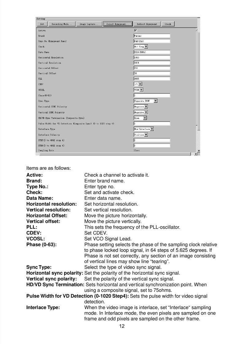
8102019 Ome44376d Vr3000 Mainte Cof26amp3bmol
httpslidepdfcomreaderfullome44376d-vr3000-mainte-cof26amp3bmol 1457
12
Items are as follows
Active Check a channel to activate it
Brand Enter brand nameType No Enter type noCheck Set and activate checkData Name Enter data nameHorizontal resolution Set horizontal resolutionVertical resolution Set vertical resolutionHorizontal Offset Move the picture horizontallyVertical offset Move the picture verticallyPLL This sets the frequency of the PLL-oscillatorCDEV Set CDEV
VCOSL Set VCO Signal LeadPhase (0-63) Phase setting selects the phase of the sampling clock relativeto phase locked loop signal in 64 steps of 5625 degrees IfPhase is not set correctly any section of an image consistingof vertical lines may show line ldquotearingrdquo
Sync Type Select the type of video sync signalHorizontal sync polarity Set the polarity of the horizontal sync signalVertical sync polarity Set the polarity of the vertical sync signalHDVD Sync Termination Sets horizontal and vertical synchronization point When
using a composite signal set to 75ohmsPulse Width for VD Detection (0-1020 Step4) Sets the pulse width for video signal
detectionInterlace Type When the video image is interlace set ldquoInterlaceldquo sampling
mode In Interlace mode the even pixels are sampled on oneframe and odd pixels are sampled on the other frame
8102019 Ome44376d Vr3000 Mainte Cof26amp3bmol
httpslidepdfcomreaderfullome44376d-vr3000-mainte-cof26amp3bmol 1557
13
Interlace Polarity Set interlace polarityITRP (0-4092 Step4) Enter interlace pulse positionITRW (0-4092 step4) Enter interlace pulse widthSampling Rate Display sampling rate Fixed at ldquo15 secondsrdquoCompress Type (viewer) Set compress type (viewer)Color Bit Display and set Color BitChange Pump Current Set pump current Fixed at ldquo05 mArdquo
Video Clock Polarity Set video clock polarity Fixed at ldquoThroughrdquoCounter Clock SelectionSelect counter clock selection Fixed at ldquo49 MHzrdquoVCO Clock Hold Sets VCO clock holdRed Gain (0-255) Enter red gainGreen Gain (0-255) Enter green gainBlue Gain (0-255) Enter blue gainRed Offset (0-255) Enter red offsetGreen Offset (0-255) Enter green offsetBlue Offset (0-255) Enter blue offsetBlack Level (0-255) Enter black levelEquipment Category Enter equipment category
Board Name Enter board name for corresponding channelNote Enter note
Note Offset Phase and Color Bit change with the length of the antenna cable
Marked Items For easy identification of input source enter Equipment Category Brand
Type No and Data Name
Measurement BoxThe Measurement Box is located on the left side of the Information Area The LOWHorizontal and Vertical counter should be higher than the HIGH counter If reversely the
HIGH counter is higher than the LOW counter it is possible that the SYNC Polaritysettings are adjusted incorrectly
8102019 Ome44376d Vr3000 Mainte Cof26amp3bmol
httpslidepdfcomreaderfullome44376d-vr3000-mainte-cof26amp3bmol 1657
14
Config Management
After all items have been set up proceed to the final setting management This can only
be executed one time after all tabs have been set up
1 Click on VDR Config Management in the Maintenance menu
2 Click on the Upload button to send all sent data to the VDR memory
3 Click each individual Write button to record to DRU Backup HDD and CF Note
If the settings are not uploaded to the VDR they have no effect on the unit
4 Click the Close button to close the VDR Config Management Dialogue Box
8102019 Ome44376d Vr3000 Mainte Cof26amp3bmol
httpslidepdfcomreaderfullome44376d-vr3000-mainte-cof26amp3bmol 1757
15
23 Serial Signal
The Serial tab sets the RS-422 signals received at the terminal board (SI01-SI08) and the
junction box (SI09-SI72) This channel is not only for NMEA but also binary and ASCII
data
Set the Serial tab as follows1 Click the Serial tab
2 Select a channel from the Information window
3 Click the Select Equipment button in the Setting Area
4 Choose the unit that is connected to the indicated Channel and click the OK Button
5 Adjust items as needed in the Setting Area
8102019 Ome44376d Vr3000 Mainte Cof26amp3bmol
httpslidepdfcomreaderfullome44376d-vr3000-mainte-cof26amp3bmol 1857
16
6 After finishing the settings for one channel click the Set buttonNote Be sure to do this before moving another channel
7 Repeat steps 2-6 to set up each channel
When running Config Management for Tab Settings
1 From the Maintenance menu click VDR Config Management and then Config
2 Click the Upload button to record data to the VDR memory3 Click the Write button to save data to the DRU backup HDD and CF
The buttons in the Setting Area are as followsSet Save edited dataCapture Received data shown in the serial window dialog boxSelect Equipment Select equipment settings (saved to the database) to reflect in
a channelReflect Equipment Save the equipment setting data to the databaseCheck Check all channels OK or NG (No Good) shown in
Information window
Individual Item ExplanationActive Put check in check box to make channel activeBrand Enter brand nameType No (Equipment Name) Set type no (equipment name)Check Do equipment checkData Name Enter data nameData Type Enter data typeBaud Rate Set baud rate (Available for SI01 to SI08)Data Bit Set number of bits (Available for SI01 to SI08)Parity Bit Set parity bit (Available for SI01 to SI08)Stop Bit Set stop bit (Available for SI01 to SI08)Source Checksum Enter checksum for GPS sourceTime out Set time outEquipment Category Set equipment categoryBoard Name Enter board names where channels are presentNote Enter note
Marked Items For easy identification of input source enter Equipment Category Brand
Type No Date and Name
8102019 Ome44376d Vr3000 Mainte Cof26amp3bmol
httpslidepdfcomreaderfullome44376d-vr3000-mainte-cof26amp3bmol 1957
17
24 Analog SignalAnalog signal is input via Junction Box IF-8530 (optional for VR-3000S)Receivable signal ndash10 to +10 V or 4 to 20mA
Connect the analog signal to V and G terminals on the Junction Box When 4 to 20 mAsignal is connected make a short circuit between the V and I input terminals with jumper
wireThe basic procedure for setting up the analog signal is as follows
1 Click the Analog tab
2 Select channel from the Information Area
3 Set detailed information of the selected channel in the Setting Area Refer to thefollowing illustration to enter detailed item information
In the factory settings there is no preset data when the Select Equipment button is
pressed In the case that the setup was completed on another ship and saved usingReflect Equipment import the data by clicking Select Equipment and choosing thesaved data
4 In the following order calibrate the Analog signal
① Click the Calibration button in the Setting Area
② Enter the voltage (or current) value for Calibration Point 1 and thecorresponding engineering value in the left and right boxes
③ Enter values for Calibration Point 2④ Enter unit for the values in Engineering Value Unit
8102019 Ome44376d Vr3000 Mainte Cof26amp3bmol
httpslidepdfcomreaderfullome44376d-vr3000-mainte-cof26amp3bmol 2057
18
In the above image the Engineering Value Unit is set to degrees (deg) TheCalibration Point 1 is -10V corresponding to 0 degrees Calibration Point 2 is10V corresponding to 30 degrees This is set corresponding to the connectedanalog sensor
When the Apply button is clicked the New Engineering Value of 29835Vcorresponding to the input Voltage of 989V is displayed in the bottom fieldWhenever the input value is changed this value also changes Check that theNew Engineering Value is within an appropriate range
Another method is to observe the Voltage (or Current) field in the top field andpress the Hold button of Point 1 when an appropriate value is displaying Dothis again for Point 2
⑤ Click the OK Button
5 When setting is complete click the Set button Be sure to do this before movinganother to channel
6 Repeat steps 1-5 to set up all channels
When using Config Manager with Tabs
1 From the Maintenance menu click VDR Config Management and then Config
2 Click the Upload button to record to VDR memory
3 Click the Write buttons to record to DRU Backup HDD and CF memory
The items in the Setting Area are as shown below Active Put check in check box to make channel activeBrand Enter brand name
Type No Set type no (equipment name)
Check Do equipment checkData Name Enter data nameData Type Analog Data type (0~10V -10~10v 4~20mV)
Sampling Rate Display sampling rateCalibration Active Disable and enable analog calibrationCalibration Point 1 Enter calibration point 1
Calibration Point 1 Value Enter calibration point 1 valueCalibration Point 2 Enter calibration point 2Calibration Point 2 Value Enter calibration point 2 valueEngineering Value Unit Enter engineering value unit
8102019 Ome44376d Vr3000 Mainte Cof26amp3bmol
httpslidepdfcomreaderfullome44376d-vr3000-mainte-cof26amp3bmol 2157
19
Note For -marked boxes values that are set at the Analog Calibration dialog box aredisplayed
Equipment Category Set equipment categoryBoard Name Enter board names where channels are presentNote Enter note
Marked Items For easy identification of input source enter Equipment CategoryBrand Type No Data and Name
25 Digital Signal
Digital signal is connected via Junction Box IF-8530 (optional for VR-3000S) The
receivable signal is 10-32 V for voltage signal or contact signal For voltage signal
connect to A and B input terminals on the Junction Box For contact signal connect to B
and G input terminals on the Junction Box Also make a short-circuit between the 24 and
A input terminals with a jumper wire
To set up the Digital tab
1 Click the Digital tab
2 Select a channel from the Information Area
3 Set up the digital signal from the Setting Area Refer to the following individual item
explanation
In the factory settings there is no preset data when the Select Equipment button is
pressed In the case that the setup was completed on another ship and saved using
Reflect Equipment import the data by clicking Select Equipment and choosing the
saved data
4 When setting Digital Signal to each 64 channel group perform the following
directions1 Click the Calibration button in the setting area
8102019 Ome44376d Vr3000 Mainte Cof26amp3bmol
httpslidepdfcomreaderfullome44376d-vr3000-mainte-cof26amp3bmol 2257
20
2 Check the active column of the channel group being set
3 Enter the status in columns 0 and 1 of that group
4 Click the OK Button
5 When finished setting up click the Set button
6 Repeat steps 2-5 to set up other channels
When using Config Manager with Tabs
1 From the Maintenance menu click VDR Config Management
2 Click the Upload button to record to VDR memory
3 Click the Write buttons to record to DRU Backup HDD and CF memory
The items in the Setting Area are as shown below
Active Put check in check box to make channel activeBrand Enter brand name
Type No Set type no (equipment name)Check Do equipment checkData Name Enter and display data nameContact Type Set contact type NO normal open NC normal closeSampling Rate Display sampling rateCalibration Active Disable and enable digital calibrationActive Status (1) Set status display when (1) is activeActive Status (0) Set status display when (0) is activeEquipment Category Set equipment categoryBoard Name Enter board names where channels are presentNote Enter note
Marked Items For easy identification of input source enter Equipment CategoryBrand Type No Date and Name
8102019 Ome44376d Vr3000 Mainte Cof26amp3bmol
httpslidepdfcomreaderfullome44376d-vr3000-mainte-cof26amp3bmol 2357
21
26 Audio
Microphone and VHF audio settings are performed in the Audio tab
Set the items in the Audio tab as shown below
1 Click the Audio tab
2 Select channel from the Information Area3 Click Select Equipment in the Setting Area
4 Click on the connected device in the indicated channel The setting contents aredisplayed in the Information and Setting Areas
5 If required update the item contents in the Setting Area Refer to the detailed itemexplanation below
6 After completing settings for a channel click the Set buttonNote Be sure to click the Set button before moving to another channel
7 Repeat steps 2-6 to set up other channels
8102019 Ome44376d Vr3000 Mainte Cof26amp3bmol
httpslidepdfcomreaderfullome44376d-vr3000-mainte-cof26amp3bmol 2457
22
When using Config Manager with tabs
1 From the Maintenance menu click VDR Config Management
2 Click the Upload button to record to VDR memory
3 Click the Write buttons to record to DRU Backup HDD and CF memory
MIC testDo the MIC test to check whether audio is received clearly in adequate level or not
1 Click the MIC TEST button in the Setting Area
2 Click the TEST button in the MIC Test dialogue box MIC test results are displayed in
the MIC Test dialogue box
3 Click the Close button to close the dialogue box
Note Not the same recordingplayback function as the previous Web Configuratorsoftware
Continuous MIC TestRun the continuous MIC test as needed accordingly
1 Click the Continuous MIC Test button in the Setting Area2 Set up how many times to perform in the Continuous MIC Test dialogue box and click
the Test button
3 Click the Close button to close the dialogue box
8102019 Ome44376d Vr3000 Mainte Cof26amp3bmol
httpslidepdfcomreaderfullome44376d-vr3000-mainte-cof26amp3bmol 2557
23
Active Put check in check box to make channel activeBrand Enter and display brand nameType No Set type no (equipment name)Check Do equipment checkData Name Enter data nameInput Type Enter input type Sampling Data Bit Displays sampling data bit rate
Sampling Frequency Displays Sampling FrequencyCodec Sets MIC typeMIC Test Active M1M3M5 Put a checkmark when performing MIC Test of M1M3M5MIS Test Active M2M4M6 Put a checkmark when performing MIC Test of M2M4M6 MIC M1M3M5 Position Enter MIC position of MIC M1M3M5MIC M2M4M6 Position Enter MIC position of MIC M2M4M6Threshold Level M1M3M5 Enter MIC test threshold level of MIC M1M3M5Threshold Level M2M4M6 Enter MIC test threshold level of MIC M2M4M6Equipment Category Set equipment categoryBoard Name Enter board names where channels are present
Note Enter note Marked Items For easy identification of input source enter Equipment Category BrandType No Date and Name
8102019 Ome44376d Vr3000 Mainte Cof26amp3bmol
httpslidepdfcomreaderfullome44376d-vr3000-mainte-cof26amp3bmol 2657
24
27 Alarm
Alarm and Alarm Status settings are found in the Alarm tab
The Alarm tab shows the following information about alarms Click the Time Categoryand Name tabs in the title bar to sort
Time Time of alarm
Category Alarm categoryName Name of alarm
Number Alarm number
Status Alarm status
Alarm Search
1 Click the Search button above the Alarm tab The Search dialogue box appears
2 Add a checkmark to any desired search items (multiple items can be selected)
Start Time Display name of alarms generated after a certain time
End Time Display name of alarms generated before a certain time
Name Display information for alarm name entered
8102019 Ome44376d Vr3000 Mainte Cof26amp3bmol
httpslidepdfcomreaderfullome44376d-vr3000-mainte-cof26amp3bmol 2757
25
Number Display information for alarm number entered
Status Display alarm status for alarm name entered
3 In the checked items column input the desired search items
4 Click the Search Button
Close the Search box to cancel a search
Note During a search the upper left Mode changes from Play to Search andDisplay search related information
8102019 Ome44376d Vr3000 Mainte Cof26amp3bmol
httpslidepdfcomreaderfullome44376d-vr3000-mainte-cof26amp3bmol 2857
26
28 Event
Click the items shown below to sort by item selected
Note You can sort the items in ascending order () descending order () and
initialization order (no symbol)
Time Time an event occurred
Category Category of an event
Name Name of an event
Contents1 Display data associated with log
Contents2 Display data associated with log
Event Search
Do the following to search events
1 Click the Search button on the upper right of the Event tab
2 In the dialogue box add a checkmark to desired search items Multiple items can bechecked
Start Time Display name of event generated after a certain time
End Time Display name of event generated before a certain time
Name Display event names entered
Number Display event numbers entered
Status Display event status entered
Enter information about the checked event to search in the character input box
3 Click the Search button
Note The mode changes from Play to Search when performing a search
8102019 Ome44376d Vr3000 Mainte Cof26amp3bmol
httpslidepdfcomreaderfullome44376d-vr3000-mainte-cof26amp3bmol 2957
27
29 Hardware
The Hardware tab provides information about the system hardware
The buttons in the Setting window work as follows
Self Check Status Display status of self check
CPU Display information about the CPU
Memory Size Display memory size
CPU Board Display status of CPU board
Audio Board Display status of Audio board
Serial Board Display status of Serial board
Radar Interface Board Display status of Radar Interface boardNote Enter and display note
Marked items are optional
8102019 Ome44376d Vr3000 Mainte Cof26amp3bmol
httpslidepdfcomreaderfullome44376d-vr3000-mainte-cof26amp3bmol 3057
28
210 JB
Connect the Junction Box to the DCU before turning on the system
The JB tab functions to set up the Junction Box
The basic procedure for setting up the Junction Box is as follows
1 Click the JB tab2 Select a Junction Box from the Information Area
3 Set up the Junction Box from the Setting Area
4 Click the Set button (Be sure to do this before moving to another channel)5 Click the Check button to perform an inspection on all channels In the Information
Area check column either OK or NG (No Good) is displayed
When using Config Manager with Tabs
1 From the Maintenance menu click VDR Config Management
2 Click the Upload button to record to VDR memory
3 Click the Write buttons to record to DRU Backup HDD and CF
The items in the Setting window work as followsActive Put check in check box to make channel activeNo Display Junction Box numberIP Address Display IP address of Junction Box acquired by VDRMAC Address Display MAC address of Junction Box acquired by VDRCheck Enable and disable equipment checkNote Enter note
Marked items are optional
8102019 Ome44376d Vr3000 Mainte Cof26amp3bmol
httpslidepdfcomreaderfullome44376d-vr3000-mainte-cof26amp3bmol 3157
29
211 Life Time
The Life Time tab controls consumable parts
The basic procedure for using the Life Time tab is as follows
1 Click the Life Time tab
2 Select a Type No in the Information Area3 Set up the chosen part from Setting Area
4 Click the Set button
Note Be sure to click the Set button before moving to set up a different Type
The items in the Setting window work as follows
Type No Enter and display type no
Data Name Enter and display data name
Level Set replacement level Legal Exchange Parts or Normal Exchange Parts
Replace Date Enter and display recommended day of replacement
Lifetime Term Not usedNote Enter and display note
The Status column of the Information Area displays as follows
OK The recommended date of replacement shown in the Replace Date
box in the Information window has not passed
Out of Date The date of replacement has passed
None The date of replacement has not been set
8102019 Ome44376d Vr3000 Mainte Cof26amp3bmol
httpslidepdfcomreaderfullome44376d-vr3000-mainte-cof26amp3bmol 3257
30
212 Network
The Network tab sets the system network
The basic procedure for setting up the system network is as follows
1 Click the Network tab
2 Select a port from the Information Area
3 Set up the network from the Setting Area
4 Click the Set button
Note1 Be sure to click the Set button before moving to set up a different Port
Note2 After setting the system network reboot the VDR to apply the settings
The items in the Setting window work as follows
LAN Type Enter LAN type Public LAN or JB LAN
MAC Address Enter MAC address
IP Address Enter IP address
Subnet Mask Enter subnet mask
Gateway Address Enter gateway address
Live Play Multicast Mode (Only JB LAN) Check box to enable live player multicast
mode
Multicast Address (Only Public LAN) Enter and display live player multicast addressNote Enter note
Marked items are optional
8102019 Ome44376d Vr3000 Mainte Cof26amp3bmol
httpslidepdfcomreaderfullome44376d-vr3000-mainte-cof26amp3bmol 3357
31
213 System
The System tab sets system related functions
The basic procedure for using the System tab is as follows
1 Click the System tab
2 Set up the chosen item from the Setting Area
3 Click the Set button
Note Be sure to click the Set button before moving to a different tab
The items in the Setting window work as follows
VDR Type Enter type of VDR
VDR Model Enter model number of VDR
Radar Interface Check Enable and disable checking of the Radar Interface board
Junction Box Count Enter number of junction boxes in system
DRU Flash Count Enter number of DRU flash disks in system Set 1 when DRU
serial no is 5000 and more Set 3 when DRU serial no is less
than 5000
DRU Capacity Display capacity of DRU
Backup HDD Capacity Display capacity of Backup HDD
VDR Config Version Display version no of VDR
VDR Config Date Display the number of hours the VDR settings have
been saved
VDR Config Code Display configuration identity code
Installation Engineer Enter name of the equipment installer
Installation Company Enter name of installers company
8102019 Ome44376d Vr3000 Mainte Cof26amp3bmol
httpslidepdfcomreaderfullome44376d-vr3000-mainte-cof26amp3bmol 3457
32
Installation Date Enter the date of the installation
MIC Test Time Enter the date of the MIC test
Note Enter note Marked items are optional
USB memory logging Do not check Enable
IEEE1394 BUS Error Auto Restart function Not used
IEEE1394 Active Node Count Do not change the default value of 3 (However set to 5
for serial number 5000 or less of DRU)
IEEE1394 Recover Process Limit Count Do not change the default value of 10
DRU Error Auto Restart function Not used
REBOOT DELAY TIME (sec) Do not change the default value of 10
LIMIT REBOOT COUNT Do not change the default value of 10
Live Player Max Connection Count The max number of Live Player V4 that can be
connected simultaneously The default no is two
but a maximum of five can be set here After you
change this option reboot the VDR to apply the
setting Disconnect the cable connected with
Live Player V4 (PC) from the VDR and thenreconnect it
214 Software
The Software tab sets and display software-related operations
The basic procedure for using the Software tab is as follows
1 Click the Software tab
2 Set up the chosen Item from the Setting Area
3 Click the Set button
8102019 Ome44376d Vr3000 Mainte Cof26amp3bmol
httpslidepdfcomreaderfullome44376d-vr3000-mainte-cof26amp3bmol 3557
33
The items in the Setting window work as follows
VDR System Program Display the VDR system program no
Process Version Display the process version
Power Distribution Unit (PDU) Display the version no of the PDU
Operation System Display the version no of the OS
Audio Driver Display the version no of the audio driverRAP Version Enter the version no of the RAP
AP Version Enter the version no of the AP
JB1-8 Boot Program Display the no of the RJB Boot program for Junction Boxes
1 to 8
JB1-8 App Program Display the no of the RJB App program for Junction Boxes
1 to 8
Watch Dog Interval Do not change the default value of 60 (Enter the process
response time A process is repeated if there is no response
within the time interval set here)
Giveup Interval Do not change the default value of 300 (Enter the restart
watch time The restarting of a process is stopped when the
number of times it has been restarted is exceeded within the
interval set here)
Refork Limit Do not change the default value of 10 (Enter the upper limit
for process restart The restarting of a process is stopped
when the number of times it has been restarted exceeds the
Give up Interval)
Note Enter note
Marked Items are optional
8102019 Ome44376d Vr3000 Mainte Cof26amp3bmol
httpslidepdfcomreaderfullome44376d-vr3000-mainte-cof26amp3bmol 3657
34
215 GPS
The GPS tab sets GPS-related parameters
The basic procedure for using the GPS tab is as follows
1 Click the GPS tab
2 Set up the chosen channel from the Information window3 Set up the chosen item in the Setting Area
4 Click the Set button
5 Repeat steps 2-4 to set up each Channel
6 Click the Check button to perform an inspection on all channels In the Information Area check column either OK or NG (No Good) is displayed
The items in the Setting window work as follows
Priority Display priority order
Date and Time SourceShip Position Source Set GPS source channel (serial channel
number for ZDA sentence)
Check Enable and disable checking
GPS Antenna Position From Bow Enter position of GPS antenna from bow
GPS Antenna Position From Stern Enter position of GPS antenna from stern
GPS Antenna Position From Port Enter position of GPS antenna from port
GPS Antenna Position From Starboard Enter position of GPS antenna from starboard
GPS Failure Threshold If the ZDA is input within the set time limit
the system restarts synchronized If not
input within the time limit the system restarts
without synchronization
8102019 Ome44376d Vr3000 Mainte Cof26amp3bmol
httpslidepdfcomreaderfullome44376d-vr3000-mainte-cof26amp3bmol 3757
35
GPS Delay Time by Time Sync Enter minimum time delay for time
synchronization Time synchronization is started
only in the time set here
GPS Difference Interval The time set here is added to the GPS time to
synchronize the system time Leave at the default
0 value setting
GPS Sync Giveup Time If the system receives the GPS time within the
time set the system synchronizes with the time
When not receiving a signal the system displays
an ldquoerror 26rdquo message
ZDA Timeout Enter value (seconds) for ZDA timeout (234 error)
from GPS
Note Enter and display note
Marked Items are optional
216 VesselThe Vessel tab sets and displays own ships information such as name and IMO number
The basic procedure for using the Vessel tab is as follows
1 Click the Vessel tab
2 Set up information in the Setting window
3 Click the Set button (Be sure to do this before moving to another port)
4 From the Maintenance menu click VDR Config Management and then Config5 Click the Write buttons to save data to the DRU backup HDD CF
The buttons in the Setting window works as follows
Vessel Name Enter name of vessel
Vessel IMO Number Enter IMO number of vessel
Vessel Flag Enter flag of vessel
Approval of Authority Enter name of approving authority
Note Enter note
Marked items are optional
8102019 Ome44376d Vr3000 Mainte Cof26amp3bmol
httpslidepdfcomreaderfullome44376d-vr3000-mainte-cof26amp3bmol 3857
36
217 Delivery
The Delivery tab functions to transmit data from the VDR to a PC via Ethernet LAN Do
not use this function during live connection
The basic procedure for using the Delivery tab is as follows
1 Click the Delivery tab
2 Click the Add button to show the Delivery Config window
3 Select protocol from the Protocol drop-down box (Unicast or Multicast)
4 Enter IP address in the IP address input box
5 Enter port number in the port number input box
6 Click the tab of the data to send (Analog Digital or Serial)
7 Select the channel of the data to send
8 If Serial was selected at step 6 select applicable data sentence from the Inactivewindow Click the right arrow to move the data sentence to the Active window
9 Click the OK button to close the Delivery Config window
10 The settings are listed in a table in the Delivery window Check the checkbox in the
Active column and then click the Set button
The buttons in the Setting window works as follows
Set Save edited settings
Add Create new delivery settings
Modify Modify selected delivery settings
Delete Delete selected delivery settings
8102019 Ome44376d Vr3000 Mainte Cof26amp3bmol
httpslidepdfcomreaderfullome44376d-vr3000-mainte-cof26amp3bmol 3957
37
3 How to Back up Configuration DataThis chapter shows how to back up configuration data to various storage media
Configuration data can be opened with Word Pad or any text editor other than Notepad
31 How to Back up Configuration Data to the Startup CompactFlash (CF)
Back up data to the startup CF after setting the VDR Configuration data is created on the
CF as a configini file
Note When the error shown below occurs during the downloading or uploading of
configuration data check the connection of the DRU Backup HDD and CF and then
upload or download the configuration data again
[CONN] Download failed
[CONN] Could not upload config file
If error occurs again re-install the VDR Maintenance Viewer
Do the following to back up data to a CF
1 Set up parameters on the tabs referring to Chapter 2
2 Click the Maintenance menu
3 Select VDR Config Management
4 Click the Upload button
5 A confirmation box appears click the OK button to start uploading to the VDR
6 Click the Write button where the arrow connects between VDR and DRU BackupHDD
7 A confirmation window appears click the OK button to save the configuration data tothe DRU and Backup HDD
8102019 Ome44376d Vr3000 Mainte Cof26amp3bmol
httpslidepdfcomreaderfullome44376d-vr3000-mainte-cof26amp3bmol 4057
38
8 Click the Write button where the arrow connects between the VDR and CF
9 A confirmation window appears click the OK button to save the configuration data tothe startup CF
10 Check that the PC VDR DRU Backup HDD and CF share the same VDR configcode
32 How to Back up Configuration Data to a PC
Configuration data saved to the PC can be edited with Wordpad and shared with other
vessels For future service ease it is recommended to backup configuration data to the
PC and have the data on board the vessel Also it is recommended to upload this data to
Furuno SMS (Service Management System) If unable to upload to Furuno SMS please
contact the Service Center Furuno Japan
To back up configuration data to the PC do as follows
1 Set up parameters on the tabs referring to Chapter 2
2 Click the Maintenance menu
3 Select VDR Config Management
4 Click the Export to button
5 A confirmation window appears click the OK button
6 Select where to save the data enter file name then click the Open button
7 Confirm that back up file is in the location selected
33 How to restore the default settings
Click the Default button on the VDR Config Management window to restore the default
settings of the DRU Backup HDD CF and VDR Maintenance Viewer
8102019 Ome44376d Vr3000 Mainte Cof26amp3bmol
httpslidepdfcomreaderfullome44376d-vr3000-mainte-cof26amp3bmol 4157
39
4 How to Upload Configuration Datafrom a PCThe procedure below shows how to upload configuration from the PC to aVR-3000VR-3000S
1 Click the Maintenance menu
2 Select VDR Config Management
3 Click the Import from button
4 The Open window appears Select configuration data and then click the Open button
5 Click the Upload button to upload data to the VR-3000VR-3000S
6 Click the Write buttons to save data to the DRU backup HDD and CF
8102019 Ome44376d Vr3000 Mainte Cof26amp3bmol
httpslidepdfcomreaderfullome44376d-vr3000-mainte-cof26amp3bmol 4257
40
5 Media ManagementThe media management feature deletes data from recording media initialization the
system etc There are two method LAN connection and Direct connection The Direct
connection takes longer time than the LAN connection Basically use the LAN connection
method
Note Initialization or creation of recording media is not available when Source Select onthe Live Player V4 is selected to Backup HDD
51 Initialization
This section shows how to delete data from the recording media Configuration data is
not deleted After performing the software configuration delete the data from the DRU
and HDD
Do the following to delete data from the DRU (LAN connection)
1 Set the PlaybackCPU switch in the DCU to the CPU position
2 Use an Ethernet cross cable to connect the PC to J14 (DATA) in the DCU (See page5)
3 Open the Tool menu
4 Select Media Management to open the VDR Media Management window
5 Check that IP address shown in the ldquoLAN Connect to IPrdquo in VDR Media Table Area isthe same as the IP address access point
6 Select ldquoLAN Connect to IPrdquo in the VDR Media Table column
8102019 Ome44376d Vr3000 Mainte Cof26amp3bmol
httpslidepdfcomreaderfullome44376d-vr3000-mainte-cof26amp3bmol 4357
41
7 Click the Analyze button A list of recording media connected to the VDR appears
Put a checkmark in the checkbox of the Select column for the DRU in the Name columnNote If there are several flash memories in the DRU all flash memories are shownCheck all flash memories shown
8 Select ldquoDRU Initializerdquo from the Operation dropdown list in the Operation area
10 Click the Run button
Do the following to delete data from the DRU (Direct connection)
1 Start Live Player V4 software
2 Open the Tool menu and select Source Select Select Live from the pull-downmenu
3 Click the Alarm tab and open Alarm History
4 Set the PlaybackCPU switch in the DCU to the Playback position
5 Wait approx 10 minutes and confirm that Alarm 174 occurs on Alarm History of LivePlayer V4
6 Connect an IEEEE1394 cable between J6 in the DCU and the PC
7 Open the Tool menu
8 Select Media Management to show the VDR Media Management window
9 Select Direct in the VDR Media Table column
10 Click the Analyze button A list of recording media connected to the VDR appears
11 Put a checkmark in the checkbox of the Select column for the DRU in the Namecolumn
Note If there are several flash memories in the DRU all flash memories are shownCheck all flash memories shown
12 Select ldquoDRU Initializerdquo from the Operation dropdown list in the Operation area
13 Enter password in the password column
14 Click the RUN button
8102019 Ome44376d Vr3000 Mainte Cof26amp3bmol
httpslidepdfcomreaderfullome44376d-vr3000-mainte-cof26amp3bmol 4457
42
Delete data from the Backup HDD as follows (LAN connection)
1 Set the PlaybackCPU switch in the DCU to the CPU position
2 Check that an Ethernet cross cable is connected between J14 in the DCU and the PC
3 Open the Tool menu
4 Select Media Management to open the VDR Media Management window
5 Check that IP address shown in the LAN Connect to IP in VDR Media Table Area is
the same as the IP address access point6 Select LAN Connect to IP in the VDR Media Table column
7 Click the Analyze button
8 A list of recording media connected to the VDR appears
9 Put a checkmark in the box of the Select column for the Backup HDD in the Namecolumn Select ldquoBackup HDD Initializerdquo from the Operation dropdown list in theOperation area
10 Click the Run button
Delete data from the Backup HDD as follows (Direct connection)
1 Start Live Player V4 software
2 Open the Tool menu and select Source Select Select Live from the pull-downmenu
3 Click the Alarm tab and open Alarm History
4 Set the PlaybackCPU switch in the DCU to the Playback position
5 Wait approx 10 minutes and confirm that Alarm 174 occurs on Alarm History of LivePlayer V4
6 Connect an IEEE1394 cable between J6 in the DCU and the PC
7 Open the Tool menu
8 Select Media Management to open the VDR Media Management window9 Select Direct in the VDR Media Table window
10 Click the Analyze button A list of recording media connected to the VDR appears
11 Put a checkmark in the check box of the Select column for the Backup HDD in theName column Select ldquoBackup HDD Initializerdquo from the Operation dropdown list in theOperation area
12 Enter password
13 Click the Run button
8102019 Ome44376d Vr3000 Mainte Cof26amp3bmol
httpslidepdfcomreaderfullome44376d-vr3000-mainte-cof26amp3bmol 4557
43
52 CreationThe Creation feature initializes recording media
Note1 This feature deletes ALL configuration data Backup all VDR configuration data
Note2 When you initialize medium that is a different format for the DRU or Backup HDDdelete all partitions with the disk management tool of Windows
Note3 When the Creation is failed try again If you can not initialize recording media tryunder condition as shown below
Do the Creation by the direct connection (When the Creation by the LAN
connection is failed)
Delete all partitions of the DRU or Backup HDD with the disk management tool of
Windows to do the Creation
If the Creation is still failed request service to repairreplace the DRU or Backup
HDD
Initialize the DRU as follows (LAN connection)
1 Set the PlaybackCPU switch in the DCU to the CPU position
2 Check that an Ethernet cross cable is connected between J14 in the DCU and the PC
3 Open the Tool menu
4 Select Media Management to open the VDR Media Management window
5 Check that IP address shown in the LAN Connect to IP in VDR Media Table Area isthe same as the IP address access point
6 Check ldquoLAN Connect to IPrdquo in the VDR Media Table column
7 Click the Analyze button A list of recording media connected to the VDR appears
8 Put a checkmark in the box of the Select column for the DRU in the Name column
Select ldquoDRU Creationrdquo from the Operation dropdown list in the Operation area
9 Click the Run button
Initialize the Backup HDD as follows (LAN connection)
1 To format the Backup HDD place a checkmark in the Select column of the listedrecord media in the Name column of the VDR Media Management dialogue box
2 From the Operation drop down list of the Operation area select ldquoBackup HDDCreation (Radar) or ldquoBackup HDD Creationrdquo
Two partition tools are available for the Backup HDD in the Media Management as
below
Backup HDD creation
This tool is used when the number of the SXGA video signal connected to the BackupHDD is the same as the DRU The same partition is created on both DRU and HDD
(1) When two SXGA video signals are recorded onto the HDD while 9-GB DRU isconnected
(2) When an SXGA video signal is recorded onto the HDD while 6-GB DRU isconnected
Backup HDD creation (radar)
This tool is used when two SXGA video signals are recorded onto the HDD with 6-GB
DRU connected The HDD has an area (radar) to record the second radar signal inaddition to the same partition as the DRU This tool cannot be used when 9-GB DRUis connected
3 Press the Run Button
8102019 Ome44376d Vr3000 Mainte Cof26amp3bmol
httpslidepdfcomreaderfullome44376d-vr3000-mainte-cof26amp3bmol 4657
44
Initialize the DRU as follows (Direct connection)
1 Start Live Player V4 software
2 Open the Tool menu and select Source Select Select Live from the pull-downmenu
3 Click the Alarm tab and open Alarm History
4 Set the PlaybackCPU switch in the DCU to the Playback position
5 Wait approx 10 minutes and confirm that Alarm 174 occurs on Alarm History of LivePlayer V4
6 Connect an IEEE1394 cable between J6 in the DCU and the PC
7 Open the Tool menu
8 Select Media Management to open the VDR Media Management window
9 Select Direct in the VDR Media Table window
10 Click the Analyze button A list of recording media connected to the VDR appears
11 Put a checkmark in the box of the Select column for the DRU and the desiredrecording media in the Name column In the Operation dropdown list of the Operationarea select ldquoDRU Creationrdquo
12 Enter password in the password column
13 Click the Run button
Initialize the Backup HDD as follows (Direct Connection)
1 To format the Backup HDD place a checkmark in the Select column of the listedrecord media in the Name column of the VDR Media Management dialogue box
2 From the Operation column of the Operation area select ldquoBackup HDD Creation(Radar) or ldquoBackup HDD Creationrdquo
Backup HDD creation
This tool is used when the number of the SXGA video signal connected to the BackupHDD is the same as the DRU The same partition is created on both DRU and HDD
(1) When two SXGA video signals are recorded onto the HDD while 9-GB DRU is
connected
(2) When an SXGA video signal is recorded onto the HDD while 6-GB DRU is
connected
Backup HDD creation (radar)
This tool is used when two SXGA video signals are recorded onto the HDD with 6-GBDRU connected The HDD has an area (radar) to record the second radar signal inaddition to the same partition as the DRU This tool cannot be used when 9-GB DRUis connected
3 Enter the password in the Password column
4 Press the Run Button
8102019 Ome44376d Vr3000 Mainte Cof26amp3bmol
httpslidepdfcomreaderfullome44376d-vr3000-mainte-cof26amp3bmol 4757
45
53 How to Enable Recording Area on the Backup HDD
This function enables writing over a recording area To prevent falsification of data all
recording areas must be saved otherwise this function is disabled To use this function push
the SAVE button Save the data before doing this procedure
Note Software version 135 or higher can enable writing over a recording area even if
all recording areas are not saved
Recording enable (LAN connection)
1 Set the PlaybackCPU switch in the DCU to the CPU position
2 Check that an Ethernet cross cable is connected between J14 in the DCU and the PC
3 Open the Tool menu
4 Select Media Management to open the VDR Media Management window
5 Check that IP address shown in the ldquoLAN Connect to IPrdquo in VDR Media Table Area isthe same as the IP address access point
6 Select ldquoLAN Connect to IPrdquo in the VDR Media Table column7 Click the Analyze button A list of recording media connected to the VDR appears
8 Put a checkmark in the box of the Select column for the Backup HDD in the Namecolumn
9 Select ldquoBackup HDD Recording Area Enablerdquo from the Operation dropdown list in theOperation area
10 Click the Run button
Recording enable (Direct connection)
1 Start Live Player V4 software
2 Open the Tool menu and select Source Select Select Live from the pull-down menu3 Click the Alarm tab and open Alarm History
4 Set the PlaybackCPU switch in the DCU to the Playback position
5 Wait approx 10 minutes and confirm that Alarm 174 occurs on Alarm History of LivePlayer V4
6 Connect an IEEE1394 cable between J6 in the DCU and the PC
7 Open the Tool menu
8 Select Media Management to open the VDR Media Management window
9 Select Direct in the VDR Media Table window
10 Click the Analyze button A list of recording media connected to the VDR appears11 Put a checkmark in the box of the Select column for the Backup HDD in the Name
column
12 Select ldquoBackup HDD Recording Area Enablerdquo from the Operation dropdown list in theOperation area
13 Enter password
14 Click the Run button
8102019 Ome44376d Vr3000 Mainte Cof26amp3bmol
httpslidepdfcomreaderfullome44376d-vr3000-mainte-cof26amp3bmol 4857
46
6 Other Functions
61 Software Management
The software download feature downloads VDR system software to the PC
To download software
1 Click the Maintenance menu
2 From the Software Management menu click Software Download to show theSoftware Download window
3 Enter the IP address 1000100 in the IP address box in the Update Server area
4 Click the Download Software button
5 The confirmation window appears click the OK button
The Software Backup Execute window shows the results of the download
Software is downloaded to C Program Files VDR Viewer Viewer Backup The software file
name is vdrtar
To Update Software
VDR system program version 16x can update the software with the procedure shownbelow
Note Do not update the file downloaded in procedures above
1 Click the Maintenance menu
2 From the Software Management menu click Software Upload to show the SoftwareUpload area
3 Click the Select button to show the Open window
4 Select update file (vdrtar) and click the Open button
8102019 Ome44376d Vr3000 Mainte Cof26amp3bmol
httpslidepdfcomreaderfullome44376d-vr3000-mainte-cof26amp3bmol 4957
47
5 Check the displayed Software information is correct
6 Enter the IP address 1000100 in the IP address box in the Update Server area
7 Enter password
8 Click the Update button
After the updating is completed the VDR is automatically restarted
Note Click the Restore button on the Software Update window to restore previoussoftware version This feature is available after updating the software
62 Password Management
The password can be changed for a serviceman to access the equipment Contact
FURUNO to get the default password to use during installation
Serviceman password
1 Click the Maintenance menu2 Select Change Serviceman Password from Password Management to show the
Change Serviceman Password window
3 Enter current password in the Old Password box
4 Enter the new password in the New Password box of the Change Password area
5 Enter new password again in the Confirm New Password box
6 Click the OK button
Audio password
The audio password set at the VDR Maintenance Viewer can be removed to enable
audio access without password1 Click the Maintenance menu
2 Select Change Audio Password from Password Management to show the Change Audio Password window
3 The confirmation window appears click the OK button
8102019 Ome44376d Vr3000 Mainte Cof26amp3bmol
httpslidepdfcomreaderfullome44376d-vr3000-mainte-cof26amp3bmol 5057
48
63 Record ComparisonThe integrity of the DRU and Backup HDD recordings can be compared This function isused by the RampD engineer for debugging
Follow the procedure as shown below
1 Click the Maintenance menu2 Select Record Comparison to show the Record Comparison window
The results are shown every 15 seconds in the Record Comparison window
8102019 Ome44376d Vr3000 Mainte Cof26amp3bmol
httpslidepdfcomreaderfullome44376d-vr3000-mainte-cof26amp3bmol 5157
49
64 Software History
This section shows you to save and configure software history (communications record)
How to save software history
Note When the error dialog appears while saving the software history restart the VDR
Maintenance Viewer
1 Click the Maintenance menu
2 Select Software History Collect
3 Click the Select button The Open dialog box appears
4 Select where to save the data then click the Open button
5 Select desired save condition then click the OK buttonNone No savingAt Once Save the software history manually Saving begins as soon as the OK button is clickedPeriodic For debugging Do not use otherwise The intervals are 30 sec 60 secand 120 secAlarm Detection For debugging Do not use otherwise Software history is savedwhen specified alarm is released Enter alarm number
How to configure software communications record
The RampD engineer uses this function for debugging Do not do this procedure unless
required Malfunction can result
1 Click the Maintenance menu
2 Select Software History Config
3 Do the followingProcess Select the type of communications record to save ALL saves allcommunications records
Detail Hide or show detailed information4 Click the Send button
8102019 Ome44376d Vr3000 Mainte Cof26amp3bmol
httpslidepdfcomreaderfullome44376d-vr3000-mainte-cof26amp3bmol 5257
50
65 Easy SetupThis feature sets equipment settings in batch and creates a data file of those settings
Default template The default template is created with the settings entered at installation
1 Click the Maintenance menu
2 Select Easy Setup to show the Template Selection window
3 Select Default Template
4 Click the Start button to show the Easy Setup window
5 Right click the channels (Radar Audio Digital Serial Analog) then select Edit toshow the Equipment Selection window
6 From the Equipment Directory window select equipment connected to the selectedchannel and then click the OK button
7 Repeat steps 5 and 6 to select equipment settings for each channel
8 Click the Save button in the Easy Setup window to show the Save window
9 Select where to save the file and enter file name
10 Click the Save button
8102019 Ome44376d Vr3000 Mainte Cof26amp3bmol
httpslidepdfcomreaderfullome44376d-vr3000-mainte-cof26amp3bmol 5357
51
Specific template Use a file already created
1 Click the Maintenance menu
2 Select Easy Setup to show the Template Selection window
3 Check Specified Template
4 Click the Select button and then select the file to edit
5 Click the Start button to show the Easy Setup window
6 Right click the channels (Radar Audio Digital Serial Analog) then select Edit toshow the Equipment Selection window
7 From the Equipment Directory window select equipment connected to the selectedchannel and then click the OK button
8 Repeat steps 6 and 7 to select equipment settings for each channel
9 Click the Save button in the Easy Setup window to show the Save window
10Select where to save the file and enter file name
11 Click the Save button
66 Equipment Management
This feature controls the import and export of equipment settings
Import data file
Import data files of equipment settings created in Easy Setup etc to the VDR
1 Click the Maintenance menu
2 Select Import from Equipment Management to show the Open window
3 Select the data file to import and click Open
Export data file
Export data files of equipment settings from the VDR to a PC
1 Click the Maintenance menu
2 Select Export from Equipment Management to show the Save window
3 Enter file name
4 Click the Save button
8102019 Ome44376d Vr3000 Mainte Cof26amp3bmol
httpslidepdfcomreaderfullome44376d-vr3000-mainte-cof26amp3bmol 5457
52
67 PC_RAP
This feature enables the same operation of the RAP (Remote Alarm Panel) from a PC
Select PC_RAP from the Tool menu to show the PC_RAP window
The buttons in the PC_RAP window function as shown below
SAVE Stop recording in the area where recording is currently being done
ACK Silence audio alarm
The PC_RAP display shows the following information with LEDs
RAP_LEDs Display the status of LEDs on the RAPSave The Save button blinks yellow when pushed When the 4 memory
areas have data recorded to them the Save button lights orange when
pushed
Normal Lights (green) where there are no unconfirmed or not restored
alarms
Error Flashes (red) for not confirmed alarm Lights (red) for unrestored
alarm
8102019 Ome44376d Vr3000 Mainte Cof26amp3bmol
httpslidepdfcomreaderfullome44376d-vr3000-mainte-cof26amp3bmol 5557
53
Backup HDD Information Display status of backup HDD
Selected Display current recording area and its status in green for
normal operation and in red for abnormal operation
Size Display capacity of backup HDD
Alarm area displays unconfirmed alarms
Time Display time alarm was generatedNumber Display number of alarm
Name Display name of alarm
Pending Alarm displays the unrestored alarms out of confirmed alarms only
Time Display time alarm was generated
Number Display number of alarm
Name Display name of alarm
8102019 Ome44376d Vr3000 Mainte Cof26amp3bmol
httpslidepdfcomreaderfullome44376d-vr3000-mainte-cof26amp3bmol 5657
54
68 Other
Status Monitor
The status monitor feature provides comprehensive data about the status of the VDR
From the menu bar click Toolgt Status Monitor to show the Status Monitor window
The buttons in the Status Monitor window work as shown below
Reload Settings for automatic refreshing of the status monitor
ON Turn automatic refresh OFF
OFF The Status Monitor is refreshed every five seconds
Save Available when Reload ON is selected The contents of the Status Monitor can be
saved to a text fileUpdate Update the Status Monitor display
Close Close the Status Monitor display
8102019 Ome44376d Vr3000 Mainte Cof26amp3bmol
httpslidepdfcomreaderfullome44376d-vr3000-mainte-cof26amp3bmol 5757
VDR Error List
This feature compiles all the errors shown on the RAP for easy reference
Access from MenugtToolgtVDR Error List
The VDR error list contains the following information
NO Display the number of the error
Title Display the name of the error
Detail Display details about the error
Exchange Check
This feature removes the alarms generated when replacing the DRU or backup HDD
Access MenugtToolgtExchange Check select either DRU or Backup HDD and click OK
Reboot
Reboot the VDR
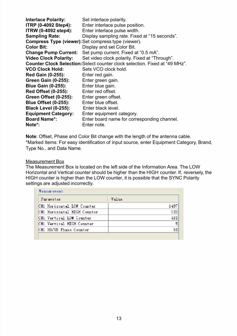
8102019 Ome44376d Vr3000 Mainte Cof26amp3bmol
httpslidepdfcomreaderfullome44376d-vr3000-mainte-cof26amp3bmol 1557
13
Interlace Polarity Set interlace polarityITRP (0-4092 Step4) Enter interlace pulse positionITRW (0-4092 step4) Enter interlace pulse widthSampling Rate Display sampling rate Fixed at ldquo15 secondsrdquoCompress Type (viewer) Set compress type (viewer)Color Bit Display and set Color BitChange Pump Current Set pump current Fixed at ldquo05 mArdquo
Video Clock Polarity Set video clock polarity Fixed at ldquoThroughrdquoCounter Clock SelectionSelect counter clock selection Fixed at ldquo49 MHzrdquoVCO Clock Hold Sets VCO clock holdRed Gain (0-255) Enter red gainGreen Gain (0-255) Enter green gainBlue Gain (0-255) Enter blue gainRed Offset (0-255) Enter red offsetGreen Offset (0-255) Enter green offsetBlue Offset (0-255) Enter blue offsetBlack Level (0-255) Enter black levelEquipment Category Enter equipment category
Board Name Enter board name for corresponding channelNote Enter note
Note Offset Phase and Color Bit change with the length of the antenna cable
Marked Items For easy identification of input source enter Equipment Category Brand
Type No and Data Name
Measurement BoxThe Measurement Box is located on the left side of the Information Area The LOWHorizontal and Vertical counter should be higher than the HIGH counter If reversely the
HIGH counter is higher than the LOW counter it is possible that the SYNC Polaritysettings are adjusted incorrectly
8102019 Ome44376d Vr3000 Mainte Cof26amp3bmol
httpslidepdfcomreaderfullome44376d-vr3000-mainte-cof26amp3bmol 1657
14
Config Management
After all items have been set up proceed to the final setting management This can only
be executed one time after all tabs have been set up
1 Click on VDR Config Management in the Maintenance menu
2 Click on the Upload button to send all sent data to the VDR memory
3 Click each individual Write button to record to DRU Backup HDD and CF Note
If the settings are not uploaded to the VDR they have no effect on the unit
4 Click the Close button to close the VDR Config Management Dialogue Box
8102019 Ome44376d Vr3000 Mainte Cof26amp3bmol
httpslidepdfcomreaderfullome44376d-vr3000-mainte-cof26amp3bmol 1757
15
23 Serial Signal
The Serial tab sets the RS-422 signals received at the terminal board (SI01-SI08) and the
junction box (SI09-SI72) This channel is not only for NMEA but also binary and ASCII
data
Set the Serial tab as follows1 Click the Serial tab
2 Select a channel from the Information window
3 Click the Select Equipment button in the Setting Area
4 Choose the unit that is connected to the indicated Channel and click the OK Button
5 Adjust items as needed in the Setting Area
8102019 Ome44376d Vr3000 Mainte Cof26amp3bmol
httpslidepdfcomreaderfullome44376d-vr3000-mainte-cof26amp3bmol 1857
16
6 After finishing the settings for one channel click the Set buttonNote Be sure to do this before moving another channel
7 Repeat steps 2-6 to set up each channel
When running Config Management for Tab Settings
1 From the Maintenance menu click VDR Config Management and then Config
2 Click the Upload button to record data to the VDR memory3 Click the Write button to save data to the DRU backup HDD and CF
The buttons in the Setting Area are as followsSet Save edited dataCapture Received data shown in the serial window dialog boxSelect Equipment Select equipment settings (saved to the database) to reflect in
a channelReflect Equipment Save the equipment setting data to the databaseCheck Check all channels OK or NG (No Good) shown in
Information window
Individual Item ExplanationActive Put check in check box to make channel activeBrand Enter brand nameType No (Equipment Name) Set type no (equipment name)Check Do equipment checkData Name Enter data nameData Type Enter data typeBaud Rate Set baud rate (Available for SI01 to SI08)Data Bit Set number of bits (Available for SI01 to SI08)Parity Bit Set parity bit (Available for SI01 to SI08)Stop Bit Set stop bit (Available for SI01 to SI08)Source Checksum Enter checksum for GPS sourceTime out Set time outEquipment Category Set equipment categoryBoard Name Enter board names where channels are presentNote Enter note
Marked Items For easy identification of input source enter Equipment Category Brand
Type No Date and Name
8102019 Ome44376d Vr3000 Mainte Cof26amp3bmol
httpslidepdfcomreaderfullome44376d-vr3000-mainte-cof26amp3bmol 1957
17
24 Analog SignalAnalog signal is input via Junction Box IF-8530 (optional for VR-3000S)Receivable signal ndash10 to +10 V or 4 to 20mA
Connect the analog signal to V and G terminals on the Junction Box When 4 to 20 mAsignal is connected make a short circuit between the V and I input terminals with jumper
wireThe basic procedure for setting up the analog signal is as follows
1 Click the Analog tab
2 Select channel from the Information Area
3 Set detailed information of the selected channel in the Setting Area Refer to thefollowing illustration to enter detailed item information
In the factory settings there is no preset data when the Select Equipment button is
pressed In the case that the setup was completed on another ship and saved usingReflect Equipment import the data by clicking Select Equipment and choosing thesaved data
4 In the following order calibrate the Analog signal
① Click the Calibration button in the Setting Area
② Enter the voltage (or current) value for Calibration Point 1 and thecorresponding engineering value in the left and right boxes
③ Enter values for Calibration Point 2④ Enter unit for the values in Engineering Value Unit
8102019 Ome44376d Vr3000 Mainte Cof26amp3bmol
httpslidepdfcomreaderfullome44376d-vr3000-mainte-cof26amp3bmol 2057
18
In the above image the Engineering Value Unit is set to degrees (deg) TheCalibration Point 1 is -10V corresponding to 0 degrees Calibration Point 2 is10V corresponding to 30 degrees This is set corresponding to the connectedanalog sensor
When the Apply button is clicked the New Engineering Value of 29835Vcorresponding to the input Voltage of 989V is displayed in the bottom fieldWhenever the input value is changed this value also changes Check that theNew Engineering Value is within an appropriate range
Another method is to observe the Voltage (or Current) field in the top field andpress the Hold button of Point 1 when an appropriate value is displaying Dothis again for Point 2
⑤ Click the OK Button
5 When setting is complete click the Set button Be sure to do this before movinganother to channel
6 Repeat steps 1-5 to set up all channels
When using Config Manager with Tabs
1 From the Maintenance menu click VDR Config Management and then Config
2 Click the Upload button to record to VDR memory
3 Click the Write buttons to record to DRU Backup HDD and CF memory
The items in the Setting Area are as shown below Active Put check in check box to make channel activeBrand Enter brand name
Type No Set type no (equipment name)
Check Do equipment checkData Name Enter data nameData Type Analog Data type (0~10V -10~10v 4~20mV)
Sampling Rate Display sampling rateCalibration Active Disable and enable analog calibrationCalibration Point 1 Enter calibration point 1
Calibration Point 1 Value Enter calibration point 1 valueCalibration Point 2 Enter calibration point 2Calibration Point 2 Value Enter calibration point 2 valueEngineering Value Unit Enter engineering value unit
8102019 Ome44376d Vr3000 Mainte Cof26amp3bmol
httpslidepdfcomreaderfullome44376d-vr3000-mainte-cof26amp3bmol 2157
19
Note For -marked boxes values that are set at the Analog Calibration dialog box aredisplayed
Equipment Category Set equipment categoryBoard Name Enter board names where channels are presentNote Enter note
Marked Items For easy identification of input source enter Equipment CategoryBrand Type No Data and Name
25 Digital Signal
Digital signal is connected via Junction Box IF-8530 (optional for VR-3000S) The
receivable signal is 10-32 V for voltage signal or contact signal For voltage signal
connect to A and B input terminals on the Junction Box For contact signal connect to B
and G input terminals on the Junction Box Also make a short-circuit between the 24 and
A input terminals with a jumper wire
To set up the Digital tab
1 Click the Digital tab
2 Select a channel from the Information Area
3 Set up the digital signal from the Setting Area Refer to the following individual item
explanation
In the factory settings there is no preset data when the Select Equipment button is
pressed In the case that the setup was completed on another ship and saved using
Reflect Equipment import the data by clicking Select Equipment and choosing the
saved data
4 When setting Digital Signal to each 64 channel group perform the following
directions1 Click the Calibration button in the setting area
8102019 Ome44376d Vr3000 Mainte Cof26amp3bmol
httpslidepdfcomreaderfullome44376d-vr3000-mainte-cof26amp3bmol 2257
20
2 Check the active column of the channel group being set
3 Enter the status in columns 0 and 1 of that group
4 Click the OK Button
5 When finished setting up click the Set button
6 Repeat steps 2-5 to set up other channels
When using Config Manager with Tabs
1 From the Maintenance menu click VDR Config Management
2 Click the Upload button to record to VDR memory
3 Click the Write buttons to record to DRU Backup HDD and CF memory
The items in the Setting Area are as shown below
Active Put check in check box to make channel activeBrand Enter brand name
Type No Set type no (equipment name)Check Do equipment checkData Name Enter and display data nameContact Type Set contact type NO normal open NC normal closeSampling Rate Display sampling rateCalibration Active Disable and enable digital calibrationActive Status (1) Set status display when (1) is activeActive Status (0) Set status display when (0) is activeEquipment Category Set equipment categoryBoard Name Enter board names where channels are presentNote Enter note
Marked Items For easy identification of input source enter Equipment CategoryBrand Type No Date and Name
8102019 Ome44376d Vr3000 Mainte Cof26amp3bmol
httpslidepdfcomreaderfullome44376d-vr3000-mainte-cof26amp3bmol 2357
21
26 Audio
Microphone and VHF audio settings are performed in the Audio tab
Set the items in the Audio tab as shown below
1 Click the Audio tab
2 Select channel from the Information Area3 Click Select Equipment in the Setting Area
4 Click on the connected device in the indicated channel The setting contents aredisplayed in the Information and Setting Areas
5 If required update the item contents in the Setting Area Refer to the detailed itemexplanation below
6 After completing settings for a channel click the Set buttonNote Be sure to click the Set button before moving to another channel
7 Repeat steps 2-6 to set up other channels
8102019 Ome44376d Vr3000 Mainte Cof26amp3bmol
httpslidepdfcomreaderfullome44376d-vr3000-mainte-cof26amp3bmol 2457
22
When using Config Manager with tabs
1 From the Maintenance menu click VDR Config Management
2 Click the Upload button to record to VDR memory
3 Click the Write buttons to record to DRU Backup HDD and CF memory
MIC testDo the MIC test to check whether audio is received clearly in adequate level or not
1 Click the MIC TEST button in the Setting Area
2 Click the TEST button in the MIC Test dialogue box MIC test results are displayed in
the MIC Test dialogue box
3 Click the Close button to close the dialogue box
Note Not the same recordingplayback function as the previous Web Configuratorsoftware
Continuous MIC TestRun the continuous MIC test as needed accordingly
1 Click the Continuous MIC Test button in the Setting Area2 Set up how many times to perform in the Continuous MIC Test dialogue box and click
the Test button
3 Click the Close button to close the dialogue box
8102019 Ome44376d Vr3000 Mainte Cof26amp3bmol
httpslidepdfcomreaderfullome44376d-vr3000-mainte-cof26amp3bmol 2557
23
Active Put check in check box to make channel activeBrand Enter and display brand nameType No Set type no (equipment name)Check Do equipment checkData Name Enter data nameInput Type Enter input type Sampling Data Bit Displays sampling data bit rate
Sampling Frequency Displays Sampling FrequencyCodec Sets MIC typeMIC Test Active M1M3M5 Put a checkmark when performing MIC Test of M1M3M5MIS Test Active M2M4M6 Put a checkmark when performing MIC Test of M2M4M6 MIC M1M3M5 Position Enter MIC position of MIC M1M3M5MIC M2M4M6 Position Enter MIC position of MIC M2M4M6Threshold Level M1M3M5 Enter MIC test threshold level of MIC M1M3M5Threshold Level M2M4M6 Enter MIC test threshold level of MIC M2M4M6Equipment Category Set equipment categoryBoard Name Enter board names where channels are present
Note Enter note Marked Items For easy identification of input source enter Equipment Category BrandType No Date and Name
8102019 Ome44376d Vr3000 Mainte Cof26amp3bmol
httpslidepdfcomreaderfullome44376d-vr3000-mainte-cof26amp3bmol 2657
24
27 Alarm
Alarm and Alarm Status settings are found in the Alarm tab
The Alarm tab shows the following information about alarms Click the Time Categoryand Name tabs in the title bar to sort
Time Time of alarm
Category Alarm categoryName Name of alarm
Number Alarm number
Status Alarm status
Alarm Search
1 Click the Search button above the Alarm tab The Search dialogue box appears
2 Add a checkmark to any desired search items (multiple items can be selected)
Start Time Display name of alarms generated after a certain time
End Time Display name of alarms generated before a certain time
Name Display information for alarm name entered
8102019 Ome44376d Vr3000 Mainte Cof26amp3bmol
httpslidepdfcomreaderfullome44376d-vr3000-mainte-cof26amp3bmol 2757
25
Number Display information for alarm number entered
Status Display alarm status for alarm name entered
3 In the checked items column input the desired search items
4 Click the Search Button
Close the Search box to cancel a search
Note During a search the upper left Mode changes from Play to Search andDisplay search related information
8102019 Ome44376d Vr3000 Mainte Cof26amp3bmol
httpslidepdfcomreaderfullome44376d-vr3000-mainte-cof26amp3bmol 2857
26
28 Event
Click the items shown below to sort by item selected
Note You can sort the items in ascending order () descending order () and
initialization order (no symbol)
Time Time an event occurred
Category Category of an event
Name Name of an event
Contents1 Display data associated with log
Contents2 Display data associated with log
Event Search
Do the following to search events
1 Click the Search button on the upper right of the Event tab
2 In the dialogue box add a checkmark to desired search items Multiple items can bechecked
Start Time Display name of event generated after a certain time
End Time Display name of event generated before a certain time
Name Display event names entered
Number Display event numbers entered
Status Display event status entered
Enter information about the checked event to search in the character input box
3 Click the Search button
Note The mode changes from Play to Search when performing a search
8102019 Ome44376d Vr3000 Mainte Cof26amp3bmol
httpslidepdfcomreaderfullome44376d-vr3000-mainte-cof26amp3bmol 2957
27
29 Hardware
The Hardware tab provides information about the system hardware
The buttons in the Setting window work as follows
Self Check Status Display status of self check
CPU Display information about the CPU
Memory Size Display memory size
CPU Board Display status of CPU board
Audio Board Display status of Audio board
Serial Board Display status of Serial board
Radar Interface Board Display status of Radar Interface boardNote Enter and display note
Marked items are optional
8102019 Ome44376d Vr3000 Mainte Cof26amp3bmol
httpslidepdfcomreaderfullome44376d-vr3000-mainte-cof26amp3bmol 3057
28
210 JB
Connect the Junction Box to the DCU before turning on the system
The JB tab functions to set up the Junction Box
The basic procedure for setting up the Junction Box is as follows
1 Click the JB tab2 Select a Junction Box from the Information Area
3 Set up the Junction Box from the Setting Area
4 Click the Set button (Be sure to do this before moving to another channel)5 Click the Check button to perform an inspection on all channels In the Information
Area check column either OK or NG (No Good) is displayed
When using Config Manager with Tabs
1 From the Maintenance menu click VDR Config Management
2 Click the Upload button to record to VDR memory
3 Click the Write buttons to record to DRU Backup HDD and CF
The items in the Setting window work as followsActive Put check in check box to make channel activeNo Display Junction Box numberIP Address Display IP address of Junction Box acquired by VDRMAC Address Display MAC address of Junction Box acquired by VDRCheck Enable and disable equipment checkNote Enter note
Marked items are optional
8102019 Ome44376d Vr3000 Mainte Cof26amp3bmol
httpslidepdfcomreaderfullome44376d-vr3000-mainte-cof26amp3bmol 3157
29
211 Life Time
The Life Time tab controls consumable parts
The basic procedure for using the Life Time tab is as follows
1 Click the Life Time tab
2 Select a Type No in the Information Area3 Set up the chosen part from Setting Area
4 Click the Set button
Note Be sure to click the Set button before moving to set up a different Type
The items in the Setting window work as follows
Type No Enter and display type no
Data Name Enter and display data name
Level Set replacement level Legal Exchange Parts or Normal Exchange Parts
Replace Date Enter and display recommended day of replacement
Lifetime Term Not usedNote Enter and display note
The Status column of the Information Area displays as follows
OK The recommended date of replacement shown in the Replace Date
box in the Information window has not passed
Out of Date The date of replacement has passed
None The date of replacement has not been set
8102019 Ome44376d Vr3000 Mainte Cof26amp3bmol
httpslidepdfcomreaderfullome44376d-vr3000-mainte-cof26amp3bmol 3257
30
212 Network
The Network tab sets the system network
The basic procedure for setting up the system network is as follows
1 Click the Network tab
2 Select a port from the Information Area
3 Set up the network from the Setting Area
4 Click the Set button
Note1 Be sure to click the Set button before moving to set up a different Port
Note2 After setting the system network reboot the VDR to apply the settings
The items in the Setting window work as follows
LAN Type Enter LAN type Public LAN or JB LAN
MAC Address Enter MAC address
IP Address Enter IP address
Subnet Mask Enter subnet mask
Gateway Address Enter gateway address
Live Play Multicast Mode (Only JB LAN) Check box to enable live player multicast
mode
Multicast Address (Only Public LAN) Enter and display live player multicast addressNote Enter note
Marked items are optional
8102019 Ome44376d Vr3000 Mainte Cof26amp3bmol
httpslidepdfcomreaderfullome44376d-vr3000-mainte-cof26amp3bmol 3357
31
213 System
The System tab sets system related functions
The basic procedure for using the System tab is as follows
1 Click the System tab
2 Set up the chosen item from the Setting Area
3 Click the Set button
Note Be sure to click the Set button before moving to a different tab
The items in the Setting window work as follows
VDR Type Enter type of VDR
VDR Model Enter model number of VDR
Radar Interface Check Enable and disable checking of the Radar Interface board
Junction Box Count Enter number of junction boxes in system
DRU Flash Count Enter number of DRU flash disks in system Set 1 when DRU
serial no is 5000 and more Set 3 when DRU serial no is less
than 5000
DRU Capacity Display capacity of DRU
Backup HDD Capacity Display capacity of Backup HDD
VDR Config Version Display version no of VDR
VDR Config Date Display the number of hours the VDR settings have
been saved
VDR Config Code Display configuration identity code
Installation Engineer Enter name of the equipment installer
Installation Company Enter name of installers company
8102019 Ome44376d Vr3000 Mainte Cof26amp3bmol
httpslidepdfcomreaderfullome44376d-vr3000-mainte-cof26amp3bmol 3457
32
Installation Date Enter the date of the installation
MIC Test Time Enter the date of the MIC test
Note Enter note Marked items are optional
USB memory logging Do not check Enable
IEEE1394 BUS Error Auto Restart function Not used
IEEE1394 Active Node Count Do not change the default value of 3 (However set to 5
for serial number 5000 or less of DRU)
IEEE1394 Recover Process Limit Count Do not change the default value of 10
DRU Error Auto Restart function Not used
REBOOT DELAY TIME (sec) Do not change the default value of 10
LIMIT REBOOT COUNT Do not change the default value of 10
Live Player Max Connection Count The max number of Live Player V4 that can be
connected simultaneously The default no is two
but a maximum of five can be set here After you
change this option reboot the VDR to apply the
setting Disconnect the cable connected with
Live Player V4 (PC) from the VDR and thenreconnect it
214 Software
The Software tab sets and display software-related operations
The basic procedure for using the Software tab is as follows
1 Click the Software tab
2 Set up the chosen Item from the Setting Area
3 Click the Set button
8102019 Ome44376d Vr3000 Mainte Cof26amp3bmol
httpslidepdfcomreaderfullome44376d-vr3000-mainte-cof26amp3bmol 3557
33
The items in the Setting window work as follows
VDR System Program Display the VDR system program no
Process Version Display the process version
Power Distribution Unit (PDU) Display the version no of the PDU
Operation System Display the version no of the OS
Audio Driver Display the version no of the audio driverRAP Version Enter the version no of the RAP
AP Version Enter the version no of the AP
JB1-8 Boot Program Display the no of the RJB Boot program for Junction Boxes
1 to 8
JB1-8 App Program Display the no of the RJB App program for Junction Boxes
1 to 8
Watch Dog Interval Do not change the default value of 60 (Enter the process
response time A process is repeated if there is no response
within the time interval set here)
Giveup Interval Do not change the default value of 300 (Enter the restart
watch time The restarting of a process is stopped when the
number of times it has been restarted is exceeded within the
interval set here)
Refork Limit Do not change the default value of 10 (Enter the upper limit
for process restart The restarting of a process is stopped
when the number of times it has been restarted exceeds the
Give up Interval)
Note Enter note
Marked Items are optional
8102019 Ome44376d Vr3000 Mainte Cof26amp3bmol
httpslidepdfcomreaderfullome44376d-vr3000-mainte-cof26amp3bmol 3657
34
215 GPS
The GPS tab sets GPS-related parameters
The basic procedure for using the GPS tab is as follows
1 Click the GPS tab
2 Set up the chosen channel from the Information window3 Set up the chosen item in the Setting Area
4 Click the Set button
5 Repeat steps 2-4 to set up each Channel
6 Click the Check button to perform an inspection on all channels In the Information Area check column either OK or NG (No Good) is displayed
The items in the Setting window work as follows
Priority Display priority order
Date and Time SourceShip Position Source Set GPS source channel (serial channel
number for ZDA sentence)
Check Enable and disable checking
GPS Antenna Position From Bow Enter position of GPS antenna from bow
GPS Antenna Position From Stern Enter position of GPS antenna from stern
GPS Antenna Position From Port Enter position of GPS antenna from port
GPS Antenna Position From Starboard Enter position of GPS antenna from starboard
GPS Failure Threshold If the ZDA is input within the set time limit
the system restarts synchronized If not
input within the time limit the system restarts
without synchronization
8102019 Ome44376d Vr3000 Mainte Cof26amp3bmol
httpslidepdfcomreaderfullome44376d-vr3000-mainte-cof26amp3bmol 3757
35
GPS Delay Time by Time Sync Enter minimum time delay for time
synchronization Time synchronization is started
only in the time set here
GPS Difference Interval The time set here is added to the GPS time to
synchronize the system time Leave at the default
0 value setting
GPS Sync Giveup Time If the system receives the GPS time within the
time set the system synchronizes with the time
When not receiving a signal the system displays
an ldquoerror 26rdquo message
ZDA Timeout Enter value (seconds) for ZDA timeout (234 error)
from GPS
Note Enter and display note
Marked Items are optional
216 VesselThe Vessel tab sets and displays own ships information such as name and IMO number
The basic procedure for using the Vessel tab is as follows
1 Click the Vessel tab
2 Set up information in the Setting window
3 Click the Set button (Be sure to do this before moving to another port)
4 From the Maintenance menu click VDR Config Management and then Config5 Click the Write buttons to save data to the DRU backup HDD CF
The buttons in the Setting window works as follows
Vessel Name Enter name of vessel
Vessel IMO Number Enter IMO number of vessel
Vessel Flag Enter flag of vessel
Approval of Authority Enter name of approving authority
Note Enter note
Marked items are optional
8102019 Ome44376d Vr3000 Mainte Cof26amp3bmol
httpslidepdfcomreaderfullome44376d-vr3000-mainte-cof26amp3bmol 3857
36
217 Delivery
The Delivery tab functions to transmit data from the VDR to a PC via Ethernet LAN Do
not use this function during live connection
The basic procedure for using the Delivery tab is as follows
1 Click the Delivery tab
2 Click the Add button to show the Delivery Config window
3 Select protocol from the Protocol drop-down box (Unicast or Multicast)
4 Enter IP address in the IP address input box
5 Enter port number in the port number input box
6 Click the tab of the data to send (Analog Digital or Serial)
7 Select the channel of the data to send
8 If Serial was selected at step 6 select applicable data sentence from the Inactivewindow Click the right arrow to move the data sentence to the Active window
9 Click the OK button to close the Delivery Config window
10 The settings are listed in a table in the Delivery window Check the checkbox in the
Active column and then click the Set button
The buttons in the Setting window works as follows
Set Save edited settings
Add Create new delivery settings
Modify Modify selected delivery settings
Delete Delete selected delivery settings
8102019 Ome44376d Vr3000 Mainte Cof26amp3bmol
httpslidepdfcomreaderfullome44376d-vr3000-mainte-cof26amp3bmol 3957
37
3 How to Back up Configuration DataThis chapter shows how to back up configuration data to various storage media
Configuration data can be opened with Word Pad or any text editor other than Notepad
31 How to Back up Configuration Data to the Startup CompactFlash (CF)
Back up data to the startup CF after setting the VDR Configuration data is created on the
CF as a configini file
Note When the error shown below occurs during the downloading or uploading of
configuration data check the connection of the DRU Backup HDD and CF and then
upload or download the configuration data again
[CONN] Download failed
[CONN] Could not upload config file
If error occurs again re-install the VDR Maintenance Viewer
Do the following to back up data to a CF
1 Set up parameters on the tabs referring to Chapter 2
2 Click the Maintenance menu
3 Select VDR Config Management
4 Click the Upload button
5 A confirmation box appears click the OK button to start uploading to the VDR
6 Click the Write button where the arrow connects between VDR and DRU BackupHDD
7 A confirmation window appears click the OK button to save the configuration data tothe DRU and Backup HDD
8102019 Ome44376d Vr3000 Mainte Cof26amp3bmol
httpslidepdfcomreaderfullome44376d-vr3000-mainte-cof26amp3bmol 4057
38
8 Click the Write button where the arrow connects between the VDR and CF
9 A confirmation window appears click the OK button to save the configuration data tothe startup CF
10 Check that the PC VDR DRU Backup HDD and CF share the same VDR configcode
32 How to Back up Configuration Data to a PC
Configuration data saved to the PC can be edited with Wordpad and shared with other
vessels For future service ease it is recommended to backup configuration data to the
PC and have the data on board the vessel Also it is recommended to upload this data to
Furuno SMS (Service Management System) If unable to upload to Furuno SMS please
contact the Service Center Furuno Japan
To back up configuration data to the PC do as follows
1 Set up parameters on the tabs referring to Chapter 2
2 Click the Maintenance menu
3 Select VDR Config Management
4 Click the Export to button
5 A confirmation window appears click the OK button
6 Select where to save the data enter file name then click the Open button
7 Confirm that back up file is in the location selected
33 How to restore the default settings
Click the Default button on the VDR Config Management window to restore the default
settings of the DRU Backup HDD CF and VDR Maintenance Viewer
8102019 Ome44376d Vr3000 Mainte Cof26amp3bmol
httpslidepdfcomreaderfullome44376d-vr3000-mainte-cof26amp3bmol 4157
39
4 How to Upload Configuration Datafrom a PCThe procedure below shows how to upload configuration from the PC to aVR-3000VR-3000S
1 Click the Maintenance menu
2 Select VDR Config Management
3 Click the Import from button
4 The Open window appears Select configuration data and then click the Open button
5 Click the Upload button to upload data to the VR-3000VR-3000S
6 Click the Write buttons to save data to the DRU backup HDD and CF
8102019 Ome44376d Vr3000 Mainte Cof26amp3bmol
httpslidepdfcomreaderfullome44376d-vr3000-mainte-cof26amp3bmol 4257
40
5 Media ManagementThe media management feature deletes data from recording media initialization the
system etc There are two method LAN connection and Direct connection The Direct
connection takes longer time than the LAN connection Basically use the LAN connection
method
Note Initialization or creation of recording media is not available when Source Select onthe Live Player V4 is selected to Backup HDD
51 Initialization
This section shows how to delete data from the recording media Configuration data is
not deleted After performing the software configuration delete the data from the DRU
and HDD
Do the following to delete data from the DRU (LAN connection)
1 Set the PlaybackCPU switch in the DCU to the CPU position
2 Use an Ethernet cross cable to connect the PC to J14 (DATA) in the DCU (See page5)
3 Open the Tool menu
4 Select Media Management to open the VDR Media Management window
5 Check that IP address shown in the ldquoLAN Connect to IPrdquo in VDR Media Table Area isthe same as the IP address access point
6 Select ldquoLAN Connect to IPrdquo in the VDR Media Table column
8102019 Ome44376d Vr3000 Mainte Cof26amp3bmol
httpslidepdfcomreaderfullome44376d-vr3000-mainte-cof26amp3bmol 4357
41
7 Click the Analyze button A list of recording media connected to the VDR appears
Put a checkmark in the checkbox of the Select column for the DRU in the Name columnNote If there are several flash memories in the DRU all flash memories are shownCheck all flash memories shown
8 Select ldquoDRU Initializerdquo from the Operation dropdown list in the Operation area
10 Click the Run button
Do the following to delete data from the DRU (Direct connection)
1 Start Live Player V4 software
2 Open the Tool menu and select Source Select Select Live from the pull-downmenu
3 Click the Alarm tab and open Alarm History
4 Set the PlaybackCPU switch in the DCU to the Playback position
5 Wait approx 10 minutes and confirm that Alarm 174 occurs on Alarm History of LivePlayer V4
6 Connect an IEEEE1394 cable between J6 in the DCU and the PC
7 Open the Tool menu
8 Select Media Management to show the VDR Media Management window
9 Select Direct in the VDR Media Table column
10 Click the Analyze button A list of recording media connected to the VDR appears
11 Put a checkmark in the checkbox of the Select column for the DRU in the Namecolumn
Note If there are several flash memories in the DRU all flash memories are shownCheck all flash memories shown
12 Select ldquoDRU Initializerdquo from the Operation dropdown list in the Operation area
13 Enter password in the password column
14 Click the RUN button
8102019 Ome44376d Vr3000 Mainte Cof26amp3bmol
httpslidepdfcomreaderfullome44376d-vr3000-mainte-cof26amp3bmol 4457
42
Delete data from the Backup HDD as follows (LAN connection)
1 Set the PlaybackCPU switch in the DCU to the CPU position
2 Check that an Ethernet cross cable is connected between J14 in the DCU and the PC
3 Open the Tool menu
4 Select Media Management to open the VDR Media Management window
5 Check that IP address shown in the LAN Connect to IP in VDR Media Table Area is
the same as the IP address access point6 Select LAN Connect to IP in the VDR Media Table column
7 Click the Analyze button
8 A list of recording media connected to the VDR appears
9 Put a checkmark in the box of the Select column for the Backup HDD in the Namecolumn Select ldquoBackup HDD Initializerdquo from the Operation dropdown list in theOperation area
10 Click the Run button
Delete data from the Backup HDD as follows (Direct connection)
1 Start Live Player V4 software
2 Open the Tool menu and select Source Select Select Live from the pull-downmenu
3 Click the Alarm tab and open Alarm History
4 Set the PlaybackCPU switch in the DCU to the Playback position
5 Wait approx 10 minutes and confirm that Alarm 174 occurs on Alarm History of LivePlayer V4
6 Connect an IEEE1394 cable between J6 in the DCU and the PC
7 Open the Tool menu
8 Select Media Management to open the VDR Media Management window9 Select Direct in the VDR Media Table window
10 Click the Analyze button A list of recording media connected to the VDR appears
11 Put a checkmark in the check box of the Select column for the Backup HDD in theName column Select ldquoBackup HDD Initializerdquo from the Operation dropdown list in theOperation area
12 Enter password
13 Click the Run button
8102019 Ome44376d Vr3000 Mainte Cof26amp3bmol
httpslidepdfcomreaderfullome44376d-vr3000-mainte-cof26amp3bmol 4557
43
52 CreationThe Creation feature initializes recording media
Note1 This feature deletes ALL configuration data Backup all VDR configuration data
Note2 When you initialize medium that is a different format for the DRU or Backup HDDdelete all partitions with the disk management tool of Windows
Note3 When the Creation is failed try again If you can not initialize recording media tryunder condition as shown below
Do the Creation by the direct connection (When the Creation by the LAN
connection is failed)
Delete all partitions of the DRU or Backup HDD with the disk management tool of
Windows to do the Creation
If the Creation is still failed request service to repairreplace the DRU or Backup
HDD
Initialize the DRU as follows (LAN connection)
1 Set the PlaybackCPU switch in the DCU to the CPU position
2 Check that an Ethernet cross cable is connected between J14 in the DCU and the PC
3 Open the Tool menu
4 Select Media Management to open the VDR Media Management window
5 Check that IP address shown in the LAN Connect to IP in VDR Media Table Area isthe same as the IP address access point
6 Check ldquoLAN Connect to IPrdquo in the VDR Media Table column
7 Click the Analyze button A list of recording media connected to the VDR appears
8 Put a checkmark in the box of the Select column for the DRU in the Name column
Select ldquoDRU Creationrdquo from the Operation dropdown list in the Operation area
9 Click the Run button
Initialize the Backup HDD as follows (LAN connection)
1 To format the Backup HDD place a checkmark in the Select column of the listedrecord media in the Name column of the VDR Media Management dialogue box
2 From the Operation drop down list of the Operation area select ldquoBackup HDDCreation (Radar) or ldquoBackup HDD Creationrdquo
Two partition tools are available for the Backup HDD in the Media Management as
below
Backup HDD creation
This tool is used when the number of the SXGA video signal connected to the BackupHDD is the same as the DRU The same partition is created on both DRU and HDD
(1) When two SXGA video signals are recorded onto the HDD while 9-GB DRU isconnected
(2) When an SXGA video signal is recorded onto the HDD while 6-GB DRU isconnected
Backup HDD creation (radar)
This tool is used when two SXGA video signals are recorded onto the HDD with 6-GB
DRU connected The HDD has an area (radar) to record the second radar signal inaddition to the same partition as the DRU This tool cannot be used when 9-GB DRUis connected
3 Press the Run Button
8102019 Ome44376d Vr3000 Mainte Cof26amp3bmol
httpslidepdfcomreaderfullome44376d-vr3000-mainte-cof26amp3bmol 4657
44
Initialize the DRU as follows (Direct connection)
1 Start Live Player V4 software
2 Open the Tool menu and select Source Select Select Live from the pull-downmenu
3 Click the Alarm tab and open Alarm History
4 Set the PlaybackCPU switch in the DCU to the Playback position
5 Wait approx 10 minutes and confirm that Alarm 174 occurs on Alarm History of LivePlayer V4
6 Connect an IEEE1394 cable between J6 in the DCU and the PC
7 Open the Tool menu
8 Select Media Management to open the VDR Media Management window
9 Select Direct in the VDR Media Table window
10 Click the Analyze button A list of recording media connected to the VDR appears
11 Put a checkmark in the box of the Select column for the DRU and the desiredrecording media in the Name column In the Operation dropdown list of the Operationarea select ldquoDRU Creationrdquo
12 Enter password in the password column
13 Click the Run button
Initialize the Backup HDD as follows (Direct Connection)
1 To format the Backup HDD place a checkmark in the Select column of the listedrecord media in the Name column of the VDR Media Management dialogue box
2 From the Operation column of the Operation area select ldquoBackup HDD Creation(Radar) or ldquoBackup HDD Creationrdquo
Backup HDD creation
This tool is used when the number of the SXGA video signal connected to the BackupHDD is the same as the DRU The same partition is created on both DRU and HDD
(1) When two SXGA video signals are recorded onto the HDD while 9-GB DRU is
connected
(2) When an SXGA video signal is recorded onto the HDD while 6-GB DRU is
connected
Backup HDD creation (radar)
This tool is used when two SXGA video signals are recorded onto the HDD with 6-GBDRU connected The HDD has an area (radar) to record the second radar signal inaddition to the same partition as the DRU This tool cannot be used when 9-GB DRUis connected
3 Enter the password in the Password column
4 Press the Run Button
8102019 Ome44376d Vr3000 Mainte Cof26amp3bmol
httpslidepdfcomreaderfullome44376d-vr3000-mainte-cof26amp3bmol 4757
45
53 How to Enable Recording Area on the Backup HDD
This function enables writing over a recording area To prevent falsification of data all
recording areas must be saved otherwise this function is disabled To use this function push
the SAVE button Save the data before doing this procedure
Note Software version 135 or higher can enable writing over a recording area even if
all recording areas are not saved
Recording enable (LAN connection)
1 Set the PlaybackCPU switch in the DCU to the CPU position
2 Check that an Ethernet cross cable is connected between J14 in the DCU and the PC
3 Open the Tool menu
4 Select Media Management to open the VDR Media Management window
5 Check that IP address shown in the ldquoLAN Connect to IPrdquo in VDR Media Table Area isthe same as the IP address access point
6 Select ldquoLAN Connect to IPrdquo in the VDR Media Table column7 Click the Analyze button A list of recording media connected to the VDR appears
8 Put a checkmark in the box of the Select column for the Backup HDD in the Namecolumn
9 Select ldquoBackup HDD Recording Area Enablerdquo from the Operation dropdown list in theOperation area
10 Click the Run button
Recording enable (Direct connection)
1 Start Live Player V4 software
2 Open the Tool menu and select Source Select Select Live from the pull-down menu3 Click the Alarm tab and open Alarm History
4 Set the PlaybackCPU switch in the DCU to the Playback position
5 Wait approx 10 minutes and confirm that Alarm 174 occurs on Alarm History of LivePlayer V4
6 Connect an IEEE1394 cable between J6 in the DCU and the PC
7 Open the Tool menu
8 Select Media Management to open the VDR Media Management window
9 Select Direct in the VDR Media Table window
10 Click the Analyze button A list of recording media connected to the VDR appears11 Put a checkmark in the box of the Select column for the Backup HDD in the Name
column
12 Select ldquoBackup HDD Recording Area Enablerdquo from the Operation dropdown list in theOperation area
13 Enter password
14 Click the Run button
8102019 Ome44376d Vr3000 Mainte Cof26amp3bmol
httpslidepdfcomreaderfullome44376d-vr3000-mainte-cof26amp3bmol 4857
46
6 Other Functions
61 Software Management
The software download feature downloads VDR system software to the PC
To download software
1 Click the Maintenance menu
2 From the Software Management menu click Software Download to show theSoftware Download window
3 Enter the IP address 1000100 in the IP address box in the Update Server area
4 Click the Download Software button
5 The confirmation window appears click the OK button
The Software Backup Execute window shows the results of the download
Software is downloaded to C Program Files VDR Viewer Viewer Backup The software file
name is vdrtar
To Update Software
VDR system program version 16x can update the software with the procedure shownbelow
Note Do not update the file downloaded in procedures above
1 Click the Maintenance menu
2 From the Software Management menu click Software Upload to show the SoftwareUpload area
3 Click the Select button to show the Open window
4 Select update file (vdrtar) and click the Open button
8102019 Ome44376d Vr3000 Mainte Cof26amp3bmol
httpslidepdfcomreaderfullome44376d-vr3000-mainte-cof26amp3bmol 4957
47
5 Check the displayed Software information is correct
6 Enter the IP address 1000100 in the IP address box in the Update Server area
7 Enter password
8 Click the Update button
After the updating is completed the VDR is automatically restarted
Note Click the Restore button on the Software Update window to restore previoussoftware version This feature is available after updating the software
62 Password Management
The password can be changed for a serviceman to access the equipment Contact
FURUNO to get the default password to use during installation
Serviceman password
1 Click the Maintenance menu2 Select Change Serviceman Password from Password Management to show the
Change Serviceman Password window
3 Enter current password in the Old Password box
4 Enter the new password in the New Password box of the Change Password area
5 Enter new password again in the Confirm New Password box
6 Click the OK button
Audio password
The audio password set at the VDR Maintenance Viewer can be removed to enable
audio access without password1 Click the Maintenance menu
2 Select Change Audio Password from Password Management to show the Change Audio Password window
3 The confirmation window appears click the OK button
8102019 Ome44376d Vr3000 Mainte Cof26amp3bmol
httpslidepdfcomreaderfullome44376d-vr3000-mainte-cof26amp3bmol 5057
48
63 Record ComparisonThe integrity of the DRU and Backup HDD recordings can be compared This function isused by the RampD engineer for debugging
Follow the procedure as shown below
1 Click the Maintenance menu2 Select Record Comparison to show the Record Comparison window
The results are shown every 15 seconds in the Record Comparison window
8102019 Ome44376d Vr3000 Mainte Cof26amp3bmol
httpslidepdfcomreaderfullome44376d-vr3000-mainte-cof26amp3bmol 5157
49
64 Software History
This section shows you to save and configure software history (communications record)
How to save software history
Note When the error dialog appears while saving the software history restart the VDR
Maintenance Viewer
1 Click the Maintenance menu
2 Select Software History Collect
3 Click the Select button The Open dialog box appears
4 Select where to save the data then click the Open button
5 Select desired save condition then click the OK buttonNone No savingAt Once Save the software history manually Saving begins as soon as the OK button is clickedPeriodic For debugging Do not use otherwise The intervals are 30 sec 60 secand 120 secAlarm Detection For debugging Do not use otherwise Software history is savedwhen specified alarm is released Enter alarm number
How to configure software communications record
The RampD engineer uses this function for debugging Do not do this procedure unless
required Malfunction can result
1 Click the Maintenance menu
2 Select Software History Config
3 Do the followingProcess Select the type of communications record to save ALL saves allcommunications records
Detail Hide or show detailed information4 Click the Send button
8102019 Ome44376d Vr3000 Mainte Cof26amp3bmol
httpslidepdfcomreaderfullome44376d-vr3000-mainte-cof26amp3bmol 5257
50
65 Easy SetupThis feature sets equipment settings in batch and creates a data file of those settings
Default template The default template is created with the settings entered at installation
1 Click the Maintenance menu
2 Select Easy Setup to show the Template Selection window
3 Select Default Template
4 Click the Start button to show the Easy Setup window
5 Right click the channels (Radar Audio Digital Serial Analog) then select Edit toshow the Equipment Selection window
6 From the Equipment Directory window select equipment connected to the selectedchannel and then click the OK button
7 Repeat steps 5 and 6 to select equipment settings for each channel
8 Click the Save button in the Easy Setup window to show the Save window
9 Select where to save the file and enter file name
10 Click the Save button
8102019 Ome44376d Vr3000 Mainte Cof26amp3bmol
httpslidepdfcomreaderfullome44376d-vr3000-mainte-cof26amp3bmol 5357
51
Specific template Use a file already created
1 Click the Maintenance menu
2 Select Easy Setup to show the Template Selection window
3 Check Specified Template
4 Click the Select button and then select the file to edit
5 Click the Start button to show the Easy Setup window
6 Right click the channels (Radar Audio Digital Serial Analog) then select Edit toshow the Equipment Selection window
7 From the Equipment Directory window select equipment connected to the selectedchannel and then click the OK button
8 Repeat steps 6 and 7 to select equipment settings for each channel
9 Click the Save button in the Easy Setup window to show the Save window
10Select where to save the file and enter file name
11 Click the Save button
66 Equipment Management
This feature controls the import and export of equipment settings
Import data file
Import data files of equipment settings created in Easy Setup etc to the VDR
1 Click the Maintenance menu
2 Select Import from Equipment Management to show the Open window
3 Select the data file to import and click Open
Export data file
Export data files of equipment settings from the VDR to a PC
1 Click the Maintenance menu
2 Select Export from Equipment Management to show the Save window
3 Enter file name
4 Click the Save button
8102019 Ome44376d Vr3000 Mainte Cof26amp3bmol
httpslidepdfcomreaderfullome44376d-vr3000-mainte-cof26amp3bmol 5457
52
67 PC_RAP
This feature enables the same operation of the RAP (Remote Alarm Panel) from a PC
Select PC_RAP from the Tool menu to show the PC_RAP window
The buttons in the PC_RAP window function as shown below
SAVE Stop recording in the area where recording is currently being done
ACK Silence audio alarm
The PC_RAP display shows the following information with LEDs
RAP_LEDs Display the status of LEDs on the RAPSave The Save button blinks yellow when pushed When the 4 memory
areas have data recorded to them the Save button lights orange when
pushed
Normal Lights (green) where there are no unconfirmed or not restored
alarms
Error Flashes (red) for not confirmed alarm Lights (red) for unrestored
alarm
8102019 Ome44376d Vr3000 Mainte Cof26amp3bmol
httpslidepdfcomreaderfullome44376d-vr3000-mainte-cof26amp3bmol 5557
53
Backup HDD Information Display status of backup HDD
Selected Display current recording area and its status in green for
normal operation and in red for abnormal operation
Size Display capacity of backup HDD
Alarm area displays unconfirmed alarms
Time Display time alarm was generatedNumber Display number of alarm
Name Display name of alarm
Pending Alarm displays the unrestored alarms out of confirmed alarms only
Time Display time alarm was generated
Number Display number of alarm
Name Display name of alarm
8102019 Ome44376d Vr3000 Mainte Cof26amp3bmol
httpslidepdfcomreaderfullome44376d-vr3000-mainte-cof26amp3bmol 5657
54
68 Other
Status Monitor
The status monitor feature provides comprehensive data about the status of the VDR
From the menu bar click Toolgt Status Monitor to show the Status Monitor window
The buttons in the Status Monitor window work as shown below
Reload Settings for automatic refreshing of the status monitor
ON Turn automatic refresh OFF
OFF The Status Monitor is refreshed every five seconds
Save Available when Reload ON is selected The contents of the Status Monitor can be
saved to a text fileUpdate Update the Status Monitor display
Close Close the Status Monitor display
8102019 Ome44376d Vr3000 Mainte Cof26amp3bmol
httpslidepdfcomreaderfullome44376d-vr3000-mainte-cof26amp3bmol 5757
VDR Error List
This feature compiles all the errors shown on the RAP for easy reference
Access from MenugtToolgtVDR Error List
The VDR error list contains the following information
NO Display the number of the error
Title Display the name of the error
Detail Display details about the error
Exchange Check
This feature removes the alarms generated when replacing the DRU or backup HDD
Access MenugtToolgtExchange Check select either DRU or Backup HDD and click OK
Reboot
Reboot the VDR
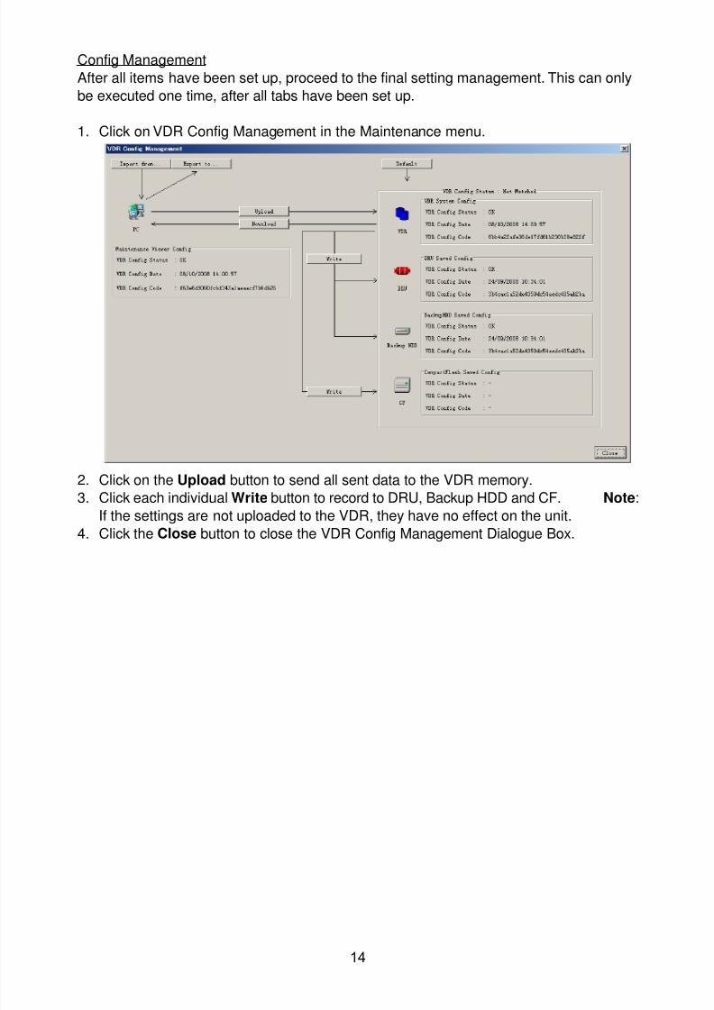
8102019 Ome44376d Vr3000 Mainte Cof26amp3bmol
httpslidepdfcomreaderfullome44376d-vr3000-mainte-cof26amp3bmol 1657
14
Config Management
After all items have been set up proceed to the final setting management This can only
be executed one time after all tabs have been set up
1 Click on VDR Config Management in the Maintenance menu
2 Click on the Upload button to send all sent data to the VDR memory
3 Click each individual Write button to record to DRU Backup HDD and CF Note
If the settings are not uploaded to the VDR they have no effect on the unit
4 Click the Close button to close the VDR Config Management Dialogue Box
8102019 Ome44376d Vr3000 Mainte Cof26amp3bmol
httpslidepdfcomreaderfullome44376d-vr3000-mainte-cof26amp3bmol 1757
15
23 Serial Signal
The Serial tab sets the RS-422 signals received at the terminal board (SI01-SI08) and the
junction box (SI09-SI72) This channel is not only for NMEA but also binary and ASCII
data
Set the Serial tab as follows1 Click the Serial tab
2 Select a channel from the Information window
3 Click the Select Equipment button in the Setting Area
4 Choose the unit that is connected to the indicated Channel and click the OK Button
5 Adjust items as needed in the Setting Area
8102019 Ome44376d Vr3000 Mainte Cof26amp3bmol
httpslidepdfcomreaderfullome44376d-vr3000-mainte-cof26amp3bmol 1857
16
6 After finishing the settings for one channel click the Set buttonNote Be sure to do this before moving another channel
7 Repeat steps 2-6 to set up each channel
When running Config Management for Tab Settings
1 From the Maintenance menu click VDR Config Management and then Config
2 Click the Upload button to record data to the VDR memory3 Click the Write button to save data to the DRU backup HDD and CF
The buttons in the Setting Area are as followsSet Save edited dataCapture Received data shown in the serial window dialog boxSelect Equipment Select equipment settings (saved to the database) to reflect in
a channelReflect Equipment Save the equipment setting data to the databaseCheck Check all channels OK or NG (No Good) shown in
Information window
Individual Item ExplanationActive Put check in check box to make channel activeBrand Enter brand nameType No (Equipment Name) Set type no (equipment name)Check Do equipment checkData Name Enter data nameData Type Enter data typeBaud Rate Set baud rate (Available for SI01 to SI08)Data Bit Set number of bits (Available for SI01 to SI08)Parity Bit Set parity bit (Available for SI01 to SI08)Stop Bit Set stop bit (Available for SI01 to SI08)Source Checksum Enter checksum for GPS sourceTime out Set time outEquipment Category Set equipment categoryBoard Name Enter board names where channels are presentNote Enter note
Marked Items For easy identification of input source enter Equipment Category Brand
Type No Date and Name
8102019 Ome44376d Vr3000 Mainte Cof26amp3bmol
httpslidepdfcomreaderfullome44376d-vr3000-mainte-cof26amp3bmol 1957
17
24 Analog SignalAnalog signal is input via Junction Box IF-8530 (optional for VR-3000S)Receivable signal ndash10 to +10 V or 4 to 20mA
Connect the analog signal to V and G terminals on the Junction Box When 4 to 20 mAsignal is connected make a short circuit between the V and I input terminals with jumper
wireThe basic procedure for setting up the analog signal is as follows
1 Click the Analog tab
2 Select channel from the Information Area
3 Set detailed information of the selected channel in the Setting Area Refer to thefollowing illustration to enter detailed item information
In the factory settings there is no preset data when the Select Equipment button is
pressed In the case that the setup was completed on another ship and saved usingReflect Equipment import the data by clicking Select Equipment and choosing thesaved data
4 In the following order calibrate the Analog signal
① Click the Calibration button in the Setting Area
② Enter the voltage (or current) value for Calibration Point 1 and thecorresponding engineering value in the left and right boxes
③ Enter values for Calibration Point 2④ Enter unit for the values in Engineering Value Unit
8102019 Ome44376d Vr3000 Mainte Cof26amp3bmol
httpslidepdfcomreaderfullome44376d-vr3000-mainte-cof26amp3bmol 2057
18
In the above image the Engineering Value Unit is set to degrees (deg) TheCalibration Point 1 is -10V corresponding to 0 degrees Calibration Point 2 is10V corresponding to 30 degrees This is set corresponding to the connectedanalog sensor
When the Apply button is clicked the New Engineering Value of 29835Vcorresponding to the input Voltage of 989V is displayed in the bottom fieldWhenever the input value is changed this value also changes Check that theNew Engineering Value is within an appropriate range
Another method is to observe the Voltage (or Current) field in the top field andpress the Hold button of Point 1 when an appropriate value is displaying Dothis again for Point 2
⑤ Click the OK Button
5 When setting is complete click the Set button Be sure to do this before movinganother to channel
6 Repeat steps 1-5 to set up all channels
When using Config Manager with Tabs
1 From the Maintenance menu click VDR Config Management and then Config
2 Click the Upload button to record to VDR memory
3 Click the Write buttons to record to DRU Backup HDD and CF memory
The items in the Setting Area are as shown below Active Put check in check box to make channel activeBrand Enter brand name
Type No Set type no (equipment name)
Check Do equipment checkData Name Enter data nameData Type Analog Data type (0~10V -10~10v 4~20mV)
Sampling Rate Display sampling rateCalibration Active Disable and enable analog calibrationCalibration Point 1 Enter calibration point 1
Calibration Point 1 Value Enter calibration point 1 valueCalibration Point 2 Enter calibration point 2Calibration Point 2 Value Enter calibration point 2 valueEngineering Value Unit Enter engineering value unit
8102019 Ome44376d Vr3000 Mainte Cof26amp3bmol
httpslidepdfcomreaderfullome44376d-vr3000-mainte-cof26amp3bmol 2157
19
Note For -marked boxes values that are set at the Analog Calibration dialog box aredisplayed
Equipment Category Set equipment categoryBoard Name Enter board names where channels are presentNote Enter note
Marked Items For easy identification of input source enter Equipment CategoryBrand Type No Data and Name
25 Digital Signal
Digital signal is connected via Junction Box IF-8530 (optional for VR-3000S) The
receivable signal is 10-32 V for voltage signal or contact signal For voltage signal
connect to A and B input terminals on the Junction Box For contact signal connect to B
and G input terminals on the Junction Box Also make a short-circuit between the 24 and
A input terminals with a jumper wire
To set up the Digital tab
1 Click the Digital tab
2 Select a channel from the Information Area
3 Set up the digital signal from the Setting Area Refer to the following individual item
explanation
In the factory settings there is no preset data when the Select Equipment button is
pressed In the case that the setup was completed on another ship and saved using
Reflect Equipment import the data by clicking Select Equipment and choosing the
saved data
4 When setting Digital Signal to each 64 channel group perform the following
directions1 Click the Calibration button in the setting area
8102019 Ome44376d Vr3000 Mainte Cof26amp3bmol
httpslidepdfcomreaderfullome44376d-vr3000-mainte-cof26amp3bmol 2257
20
2 Check the active column of the channel group being set
3 Enter the status in columns 0 and 1 of that group
4 Click the OK Button
5 When finished setting up click the Set button
6 Repeat steps 2-5 to set up other channels
When using Config Manager with Tabs
1 From the Maintenance menu click VDR Config Management
2 Click the Upload button to record to VDR memory
3 Click the Write buttons to record to DRU Backup HDD and CF memory
The items in the Setting Area are as shown below
Active Put check in check box to make channel activeBrand Enter brand name
Type No Set type no (equipment name)Check Do equipment checkData Name Enter and display data nameContact Type Set contact type NO normal open NC normal closeSampling Rate Display sampling rateCalibration Active Disable and enable digital calibrationActive Status (1) Set status display when (1) is activeActive Status (0) Set status display when (0) is activeEquipment Category Set equipment categoryBoard Name Enter board names where channels are presentNote Enter note
Marked Items For easy identification of input source enter Equipment CategoryBrand Type No Date and Name
8102019 Ome44376d Vr3000 Mainte Cof26amp3bmol
httpslidepdfcomreaderfullome44376d-vr3000-mainte-cof26amp3bmol 2357
21
26 Audio
Microphone and VHF audio settings are performed in the Audio tab
Set the items in the Audio tab as shown below
1 Click the Audio tab
2 Select channel from the Information Area3 Click Select Equipment in the Setting Area
4 Click on the connected device in the indicated channel The setting contents aredisplayed in the Information and Setting Areas
5 If required update the item contents in the Setting Area Refer to the detailed itemexplanation below
6 After completing settings for a channel click the Set buttonNote Be sure to click the Set button before moving to another channel
7 Repeat steps 2-6 to set up other channels
8102019 Ome44376d Vr3000 Mainte Cof26amp3bmol
httpslidepdfcomreaderfullome44376d-vr3000-mainte-cof26amp3bmol 2457
22
When using Config Manager with tabs
1 From the Maintenance menu click VDR Config Management
2 Click the Upload button to record to VDR memory
3 Click the Write buttons to record to DRU Backup HDD and CF memory
MIC testDo the MIC test to check whether audio is received clearly in adequate level or not
1 Click the MIC TEST button in the Setting Area
2 Click the TEST button in the MIC Test dialogue box MIC test results are displayed in
the MIC Test dialogue box
3 Click the Close button to close the dialogue box
Note Not the same recordingplayback function as the previous Web Configuratorsoftware
Continuous MIC TestRun the continuous MIC test as needed accordingly
1 Click the Continuous MIC Test button in the Setting Area2 Set up how many times to perform in the Continuous MIC Test dialogue box and click
the Test button
3 Click the Close button to close the dialogue box
8102019 Ome44376d Vr3000 Mainte Cof26amp3bmol
httpslidepdfcomreaderfullome44376d-vr3000-mainte-cof26amp3bmol 2557
23
Active Put check in check box to make channel activeBrand Enter and display brand nameType No Set type no (equipment name)Check Do equipment checkData Name Enter data nameInput Type Enter input type Sampling Data Bit Displays sampling data bit rate
Sampling Frequency Displays Sampling FrequencyCodec Sets MIC typeMIC Test Active M1M3M5 Put a checkmark when performing MIC Test of M1M3M5MIS Test Active M2M4M6 Put a checkmark when performing MIC Test of M2M4M6 MIC M1M3M5 Position Enter MIC position of MIC M1M3M5MIC M2M4M6 Position Enter MIC position of MIC M2M4M6Threshold Level M1M3M5 Enter MIC test threshold level of MIC M1M3M5Threshold Level M2M4M6 Enter MIC test threshold level of MIC M2M4M6Equipment Category Set equipment categoryBoard Name Enter board names where channels are present
Note Enter note Marked Items For easy identification of input source enter Equipment Category BrandType No Date and Name
8102019 Ome44376d Vr3000 Mainte Cof26amp3bmol
httpslidepdfcomreaderfullome44376d-vr3000-mainte-cof26amp3bmol 2657
24
27 Alarm
Alarm and Alarm Status settings are found in the Alarm tab
The Alarm tab shows the following information about alarms Click the Time Categoryand Name tabs in the title bar to sort
Time Time of alarm
Category Alarm categoryName Name of alarm
Number Alarm number
Status Alarm status
Alarm Search
1 Click the Search button above the Alarm tab The Search dialogue box appears
2 Add a checkmark to any desired search items (multiple items can be selected)
Start Time Display name of alarms generated after a certain time
End Time Display name of alarms generated before a certain time
Name Display information for alarm name entered
8102019 Ome44376d Vr3000 Mainte Cof26amp3bmol
httpslidepdfcomreaderfullome44376d-vr3000-mainte-cof26amp3bmol 2757
25
Number Display information for alarm number entered
Status Display alarm status for alarm name entered
3 In the checked items column input the desired search items
4 Click the Search Button
Close the Search box to cancel a search
Note During a search the upper left Mode changes from Play to Search andDisplay search related information
8102019 Ome44376d Vr3000 Mainte Cof26amp3bmol
httpslidepdfcomreaderfullome44376d-vr3000-mainte-cof26amp3bmol 2857
26
28 Event
Click the items shown below to sort by item selected
Note You can sort the items in ascending order () descending order () and
initialization order (no symbol)
Time Time an event occurred
Category Category of an event
Name Name of an event
Contents1 Display data associated with log
Contents2 Display data associated with log
Event Search
Do the following to search events
1 Click the Search button on the upper right of the Event tab
2 In the dialogue box add a checkmark to desired search items Multiple items can bechecked
Start Time Display name of event generated after a certain time
End Time Display name of event generated before a certain time
Name Display event names entered
Number Display event numbers entered
Status Display event status entered
Enter information about the checked event to search in the character input box
3 Click the Search button
Note The mode changes from Play to Search when performing a search
8102019 Ome44376d Vr3000 Mainte Cof26amp3bmol
httpslidepdfcomreaderfullome44376d-vr3000-mainte-cof26amp3bmol 2957
27
29 Hardware
The Hardware tab provides information about the system hardware
The buttons in the Setting window work as follows
Self Check Status Display status of self check
CPU Display information about the CPU
Memory Size Display memory size
CPU Board Display status of CPU board
Audio Board Display status of Audio board
Serial Board Display status of Serial board
Radar Interface Board Display status of Radar Interface boardNote Enter and display note
Marked items are optional
8102019 Ome44376d Vr3000 Mainte Cof26amp3bmol
httpslidepdfcomreaderfullome44376d-vr3000-mainte-cof26amp3bmol 3057
28
210 JB
Connect the Junction Box to the DCU before turning on the system
The JB tab functions to set up the Junction Box
The basic procedure for setting up the Junction Box is as follows
1 Click the JB tab2 Select a Junction Box from the Information Area
3 Set up the Junction Box from the Setting Area
4 Click the Set button (Be sure to do this before moving to another channel)5 Click the Check button to perform an inspection on all channels In the Information
Area check column either OK or NG (No Good) is displayed
When using Config Manager with Tabs
1 From the Maintenance menu click VDR Config Management
2 Click the Upload button to record to VDR memory
3 Click the Write buttons to record to DRU Backup HDD and CF
The items in the Setting window work as followsActive Put check in check box to make channel activeNo Display Junction Box numberIP Address Display IP address of Junction Box acquired by VDRMAC Address Display MAC address of Junction Box acquired by VDRCheck Enable and disable equipment checkNote Enter note
Marked items are optional
8102019 Ome44376d Vr3000 Mainte Cof26amp3bmol
httpslidepdfcomreaderfullome44376d-vr3000-mainte-cof26amp3bmol 3157
29
211 Life Time
The Life Time tab controls consumable parts
The basic procedure for using the Life Time tab is as follows
1 Click the Life Time tab
2 Select a Type No in the Information Area3 Set up the chosen part from Setting Area
4 Click the Set button
Note Be sure to click the Set button before moving to set up a different Type
The items in the Setting window work as follows
Type No Enter and display type no
Data Name Enter and display data name
Level Set replacement level Legal Exchange Parts or Normal Exchange Parts
Replace Date Enter and display recommended day of replacement
Lifetime Term Not usedNote Enter and display note
The Status column of the Information Area displays as follows
OK The recommended date of replacement shown in the Replace Date
box in the Information window has not passed
Out of Date The date of replacement has passed
None The date of replacement has not been set
8102019 Ome44376d Vr3000 Mainte Cof26amp3bmol
httpslidepdfcomreaderfullome44376d-vr3000-mainte-cof26amp3bmol 3257
30
212 Network
The Network tab sets the system network
The basic procedure for setting up the system network is as follows
1 Click the Network tab
2 Select a port from the Information Area
3 Set up the network from the Setting Area
4 Click the Set button
Note1 Be sure to click the Set button before moving to set up a different Port
Note2 After setting the system network reboot the VDR to apply the settings
The items in the Setting window work as follows
LAN Type Enter LAN type Public LAN or JB LAN
MAC Address Enter MAC address
IP Address Enter IP address
Subnet Mask Enter subnet mask
Gateway Address Enter gateway address
Live Play Multicast Mode (Only JB LAN) Check box to enable live player multicast
mode
Multicast Address (Only Public LAN) Enter and display live player multicast addressNote Enter note
Marked items are optional
8102019 Ome44376d Vr3000 Mainte Cof26amp3bmol
httpslidepdfcomreaderfullome44376d-vr3000-mainte-cof26amp3bmol 3357
31
213 System
The System tab sets system related functions
The basic procedure for using the System tab is as follows
1 Click the System tab
2 Set up the chosen item from the Setting Area
3 Click the Set button
Note Be sure to click the Set button before moving to a different tab
The items in the Setting window work as follows
VDR Type Enter type of VDR
VDR Model Enter model number of VDR
Radar Interface Check Enable and disable checking of the Radar Interface board
Junction Box Count Enter number of junction boxes in system
DRU Flash Count Enter number of DRU flash disks in system Set 1 when DRU
serial no is 5000 and more Set 3 when DRU serial no is less
than 5000
DRU Capacity Display capacity of DRU
Backup HDD Capacity Display capacity of Backup HDD
VDR Config Version Display version no of VDR
VDR Config Date Display the number of hours the VDR settings have
been saved
VDR Config Code Display configuration identity code
Installation Engineer Enter name of the equipment installer
Installation Company Enter name of installers company
8102019 Ome44376d Vr3000 Mainte Cof26amp3bmol
httpslidepdfcomreaderfullome44376d-vr3000-mainte-cof26amp3bmol 3457
32
Installation Date Enter the date of the installation
MIC Test Time Enter the date of the MIC test
Note Enter note Marked items are optional
USB memory logging Do not check Enable
IEEE1394 BUS Error Auto Restart function Not used
IEEE1394 Active Node Count Do not change the default value of 3 (However set to 5
for serial number 5000 or less of DRU)
IEEE1394 Recover Process Limit Count Do not change the default value of 10
DRU Error Auto Restart function Not used
REBOOT DELAY TIME (sec) Do not change the default value of 10
LIMIT REBOOT COUNT Do not change the default value of 10
Live Player Max Connection Count The max number of Live Player V4 that can be
connected simultaneously The default no is two
but a maximum of five can be set here After you
change this option reboot the VDR to apply the
setting Disconnect the cable connected with
Live Player V4 (PC) from the VDR and thenreconnect it
214 Software
The Software tab sets and display software-related operations
The basic procedure for using the Software tab is as follows
1 Click the Software tab
2 Set up the chosen Item from the Setting Area
3 Click the Set button
8102019 Ome44376d Vr3000 Mainte Cof26amp3bmol
httpslidepdfcomreaderfullome44376d-vr3000-mainte-cof26amp3bmol 3557
33
The items in the Setting window work as follows
VDR System Program Display the VDR system program no
Process Version Display the process version
Power Distribution Unit (PDU) Display the version no of the PDU
Operation System Display the version no of the OS
Audio Driver Display the version no of the audio driverRAP Version Enter the version no of the RAP
AP Version Enter the version no of the AP
JB1-8 Boot Program Display the no of the RJB Boot program for Junction Boxes
1 to 8
JB1-8 App Program Display the no of the RJB App program for Junction Boxes
1 to 8
Watch Dog Interval Do not change the default value of 60 (Enter the process
response time A process is repeated if there is no response
within the time interval set here)
Giveup Interval Do not change the default value of 300 (Enter the restart
watch time The restarting of a process is stopped when the
number of times it has been restarted is exceeded within the
interval set here)
Refork Limit Do not change the default value of 10 (Enter the upper limit
for process restart The restarting of a process is stopped
when the number of times it has been restarted exceeds the
Give up Interval)
Note Enter note
Marked Items are optional
8102019 Ome44376d Vr3000 Mainte Cof26amp3bmol
httpslidepdfcomreaderfullome44376d-vr3000-mainte-cof26amp3bmol 3657
34
215 GPS
The GPS tab sets GPS-related parameters
The basic procedure for using the GPS tab is as follows
1 Click the GPS tab
2 Set up the chosen channel from the Information window3 Set up the chosen item in the Setting Area
4 Click the Set button
5 Repeat steps 2-4 to set up each Channel
6 Click the Check button to perform an inspection on all channels In the Information Area check column either OK or NG (No Good) is displayed
The items in the Setting window work as follows
Priority Display priority order
Date and Time SourceShip Position Source Set GPS source channel (serial channel
number for ZDA sentence)
Check Enable and disable checking
GPS Antenna Position From Bow Enter position of GPS antenna from bow
GPS Antenna Position From Stern Enter position of GPS antenna from stern
GPS Antenna Position From Port Enter position of GPS antenna from port
GPS Antenna Position From Starboard Enter position of GPS antenna from starboard
GPS Failure Threshold If the ZDA is input within the set time limit
the system restarts synchronized If not
input within the time limit the system restarts
without synchronization
8102019 Ome44376d Vr3000 Mainte Cof26amp3bmol
httpslidepdfcomreaderfullome44376d-vr3000-mainte-cof26amp3bmol 3757
35
GPS Delay Time by Time Sync Enter minimum time delay for time
synchronization Time synchronization is started
only in the time set here
GPS Difference Interval The time set here is added to the GPS time to
synchronize the system time Leave at the default
0 value setting
GPS Sync Giveup Time If the system receives the GPS time within the
time set the system synchronizes with the time
When not receiving a signal the system displays
an ldquoerror 26rdquo message
ZDA Timeout Enter value (seconds) for ZDA timeout (234 error)
from GPS
Note Enter and display note
Marked Items are optional
216 VesselThe Vessel tab sets and displays own ships information such as name and IMO number
The basic procedure for using the Vessel tab is as follows
1 Click the Vessel tab
2 Set up information in the Setting window
3 Click the Set button (Be sure to do this before moving to another port)
4 From the Maintenance menu click VDR Config Management and then Config5 Click the Write buttons to save data to the DRU backup HDD CF
The buttons in the Setting window works as follows
Vessel Name Enter name of vessel
Vessel IMO Number Enter IMO number of vessel
Vessel Flag Enter flag of vessel
Approval of Authority Enter name of approving authority
Note Enter note
Marked items are optional
8102019 Ome44376d Vr3000 Mainte Cof26amp3bmol
httpslidepdfcomreaderfullome44376d-vr3000-mainte-cof26amp3bmol 3857
36
217 Delivery
The Delivery tab functions to transmit data from the VDR to a PC via Ethernet LAN Do
not use this function during live connection
The basic procedure for using the Delivery tab is as follows
1 Click the Delivery tab
2 Click the Add button to show the Delivery Config window
3 Select protocol from the Protocol drop-down box (Unicast or Multicast)
4 Enter IP address in the IP address input box
5 Enter port number in the port number input box
6 Click the tab of the data to send (Analog Digital or Serial)
7 Select the channel of the data to send
8 If Serial was selected at step 6 select applicable data sentence from the Inactivewindow Click the right arrow to move the data sentence to the Active window
9 Click the OK button to close the Delivery Config window
10 The settings are listed in a table in the Delivery window Check the checkbox in the
Active column and then click the Set button
The buttons in the Setting window works as follows
Set Save edited settings
Add Create new delivery settings
Modify Modify selected delivery settings
Delete Delete selected delivery settings
8102019 Ome44376d Vr3000 Mainte Cof26amp3bmol
httpslidepdfcomreaderfullome44376d-vr3000-mainte-cof26amp3bmol 3957
37
3 How to Back up Configuration DataThis chapter shows how to back up configuration data to various storage media
Configuration data can be opened with Word Pad or any text editor other than Notepad
31 How to Back up Configuration Data to the Startup CompactFlash (CF)
Back up data to the startup CF after setting the VDR Configuration data is created on the
CF as a configini file
Note When the error shown below occurs during the downloading or uploading of
configuration data check the connection of the DRU Backup HDD and CF and then
upload or download the configuration data again
[CONN] Download failed
[CONN] Could not upload config file
If error occurs again re-install the VDR Maintenance Viewer
Do the following to back up data to a CF
1 Set up parameters on the tabs referring to Chapter 2
2 Click the Maintenance menu
3 Select VDR Config Management
4 Click the Upload button
5 A confirmation box appears click the OK button to start uploading to the VDR
6 Click the Write button where the arrow connects between VDR and DRU BackupHDD
7 A confirmation window appears click the OK button to save the configuration data tothe DRU and Backup HDD
8102019 Ome44376d Vr3000 Mainte Cof26amp3bmol
httpslidepdfcomreaderfullome44376d-vr3000-mainte-cof26amp3bmol 4057
38
8 Click the Write button where the arrow connects between the VDR and CF
9 A confirmation window appears click the OK button to save the configuration data tothe startup CF
10 Check that the PC VDR DRU Backup HDD and CF share the same VDR configcode
32 How to Back up Configuration Data to a PC
Configuration data saved to the PC can be edited with Wordpad and shared with other
vessels For future service ease it is recommended to backup configuration data to the
PC and have the data on board the vessel Also it is recommended to upload this data to
Furuno SMS (Service Management System) If unable to upload to Furuno SMS please
contact the Service Center Furuno Japan
To back up configuration data to the PC do as follows
1 Set up parameters on the tabs referring to Chapter 2
2 Click the Maintenance menu
3 Select VDR Config Management
4 Click the Export to button
5 A confirmation window appears click the OK button
6 Select where to save the data enter file name then click the Open button
7 Confirm that back up file is in the location selected
33 How to restore the default settings
Click the Default button on the VDR Config Management window to restore the default
settings of the DRU Backup HDD CF and VDR Maintenance Viewer
8102019 Ome44376d Vr3000 Mainte Cof26amp3bmol
httpslidepdfcomreaderfullome44376d-vr3000-mainte-cof26amp3bmol 4157
39
4 How to Upload Configuration Datafrom a PCThe procedure below shows how to upload configuration from the PC to aVR-3000VR-3000S
1 Click the Maintenance menu
2 Select VDR Config Management
3 Click the Import from button
4 The Open window appears Select configuration data and then click the Open button
5 Click the Upload button to upload data to the VR-3000VR-3000S
6 Click the Write buttons to save data to the DRU backup HDD and CF
8102019 Ome44376d Vr3000 Mainte Cof26amp3bmol
httpslidepdfcomreaderfullome44376d-vr3000-mainte-cof26amp3bmol 4257
40
5 Media ManagementThe media management feature deletes data from recording media initialization the
system etc There are two method LAN connection and Direct connection The Direct
connection takes longer time than the LAN connection Basically use the LAN connection
method
Note Initialization or creation of recording media is not available when Source Select onthe Live Player V4 is selected to Backup HDD
51 Initialization
This section shows how to delete data from the recording media Configuration data is
not deleted After performing the software configuration delete the data from the DRU
and HDD
Do the following to delete data from the DRU (LAN connection)
1 Set the PlaybackCPU switch in the DCU to the CPU position
2 Use an Ethernet cross cable to connect the PC to J14 (DATA) in the DCU (See page5)
3 Open the Tool menu
4 Select Media Management to open the VDR Media Management window
5 Check that IP address shown in the ldquoLAN Connect to IPrdquo in VDR Media Table Area isthe same as the IP address access point
6 Select ldquoLAN Connect to IPrdquo in the VDR Media Table column
8102019 Ome44376d Vr3000 Mainte Cof26amp3bmol
httpslidepdfcomreaderfullome44376d-vr3000-mainte-cof26amp3bmol 4357
41
7 Click the Analyze button A list of recording media connected to the VDR appears
Put a checkmark in the checkbox of the Select column for the DRU in the Name columnNote If there are several flash memories in the DRU all flash memories are shownCheck all flash memories shown
8 Select ldquoDRU Initializerdquo from the Operation dropdown list in the Operation area
10 Click the Run button
Do the following to delete data from the DRU (Direct connection)
1 Start Live Player V4 software
2 Open the Tool menu and select Source Select Select Live from the pull-downmenu
3 Click the Alarm tab and open Alarm History
4 Set the PlaybackCPU switch in the DCU to the Playback position
5 Wait approx 10 minutes and confirm that Alarm 174 occurs on Alarm History of LivePlayer V4
6 Connect an IEEEE1394 cable between J6 in the DCU and the PC
7 Open the Tool menu
8 Select Media Management to show the VDR Media Management window
9 Select Direct in the VDR Media Table column
10 Click the Analyze button A list of recording media connected to the VDR appears
11 Put a checkmark in the checkbox of the Select column for the DRU in the Namecolumn
Note If there are several flash memories in the DRU all flash memories are shownCheck all flash memories shown
12 Select ldquoDRU Initializerdquo from the Operation dropdown list in the Operation area
13 Enter password in the password column
14 Click the RUN button
8102019 Ome44376d Vr3000 Mainte Cof26amp3bmol
httpslidepdfcomreaderfullome44376d-vr3000-mainte-cof26amp3bmol 4457
42
Delete data from the Backup HDD as follows (LAN connection)
1 Set the PlaybackCPU switch in the DCU to the CPU position
2 Check that an Ethernet cross cable is connected between J14 in the DCU and the PC
3 Open the Tool menu
4 Select Media Management to open the VDR Media Management window
5 Check that IP address shown in the LAN Connect to IP in VDR Media Table Area is
the same as the IP address access point6 Select LAN Connect to IP in the VDR Media Table column
7 Click the Analyze button
8 A list of recording media connected to the VDR appears
9 Put a checkmark in the box of the Select column for the Backup HDD in the Namecolumn Select ldquoBackup HDD Initializerdquo from the Operation dropdown list in theOperation area
10 Click the Run button
Delete data from the Backup HDD as follows (Direct connection)
1 Start Live Player V4 software
2 Open the Tool menu and select Source Select Select Live from the pull-downmenu
3 Click the Alarm tab and open Alarm History
4 Set the PlaybackCPU switch in the DCU to the Playback position
5 Wait approx 10 minutes and confirm that Alarm 174 occurs on Alarm History of LivePlayer V4
6 Connect an IEEE1394 cable between J6 in the DCU and the PC
7 Open the Tool menu
8 Select Media Management to open the VDR Media Management window9 Select Direct in the VDR Media Table window
10 Click the Analyze button A list of recording media connected to the VDR appears
11 Put a checkmark in the check box of the Select column for the Backup HDD in theName column Select ldquoBackup HDD Initializerdquo from the Operation dropdown list in theOperation area
12 Enter password
13 Click the Run button
8102019 Ome44376d Vr3000 Mainte Cof26amp3bmol
httpslidepdfcomreaderfullome44376d-vr3000-mainte-cof26amp3bmol 4557
43
52 CreationThe Creation feature initializes recording media
Note1 This feature deletes ALL configuration data Backup all VDR configuration data
Note2 When you initialize medium that is a different format for the DRU or Backup HDDdelete all partitions with the disk management tool of Windows
Note3 When the Creation is failed try again If you can not initialize recording media tryunder condition as shown below
Do the Creation by the direct connection (When the Creation by the LAN
connection is failed)
Delete all partitions of the DRU or Backup HDD with the disk management tool of
Windows to do the Creation
If the Creation is still failed request service to repairreplace the DRU or Backup
HDD
Initialize the DRU as follows (LAN connection)
1 Set the PlaybackCPU switch in the DCU to the CPU position
2 Check that an Ethernet cross cable is connected between J14 in the DCU and the PC
3 Open the Tool menu
4 Select Media Management to open the VDR Media Management window
5 Check that IP address shown in the LAN Connect to IP in VDR Media Table Area isthe same as the IP address access point
6 Check ldquoLAN Connect to IPrdquo in the VDR Media Table column
7 Click the Analyze button A list of recording media connected to the VDR appears
8 Put a checkmark in the box of the Select column for the DRU in the Name column
Select ldquoDRU Creationrdquo from the Operation dropdown list in the Operation area
9 Click the Run button
Initialize the Backup HDD as follows (LAN connection)
1 To format the Backup HDD place a checkmark in the Select column of the listedrecord media in the Name column of the VDR Media Management dialogue box
2 From the Operation drop down list of the Operation area select ldquoBackup HDDCreation (Radar) or ldquoBackup HDD Creationrdquo
Two partition tools are available for the Backup HDD in the Media Management as
below
Backup HDD creation
This tool is used when the number of the SXGA video signal connected to the BackupHDD is the same as the DRU The same partition is created on both DRU and HDD
(1) When two SXGA video signals are recorded onto the HDD while 9-GB DRU isconnected
(2) When an SXGA video signal is recorded onto the HDD while 6-GB DRU isconnected
Backup HDD creation (radar)
This tool is used when two SXGA video signals are recorded onto the HDD with 6-GB
DRU connected The HDD has an area (radar) to record the second radar signal inaddition to the same partition as the DRU This tool cannot be used when 9-GB DRUis connected
3 Press the Run Button
8102019 Ome44376d Vr3000 Mainte Cof26amp3bmol
httpslidepdfcomreaderfullome44376d-vr3000-mainte-cof26amp3bmol 4657
44
Initialize the DRU as follows (Direct connection)
1 Start Live Player V4 software
2 Open the Tool menu and select Source Select Select Live from the pull-downmenu
3 Click the Alarm tab and open Alarm History
4 Set the PlaybackCPU switch in the DCU to the Playback position
5 Wait approx 10 minutes and confirm that Alarm 174 occurs on Alarm History of LivePlayer V4
6 Connect an IEEE1394 cable between J6 in the DCU and the PC
7 Open the Tool menu
8 Select Media Management to open the VDR Media Management window
9 Select Direct in the VDR Media Table window
10 Click the Analyze button A list of recording media connected to the VDR appears
11 Put a checkmark in the box of the Select column for the DRU and the desiredrecording media in the Name column In the Operation dropdown list of the Operationarea select ldquoDRU Creationrdquo
12 Enter password in the password column
13 Click the Run button
Initialize the Backup HDD as follows (Direct Connection)
1 To format the Backup HDD place a checkmark in the Select column of the listedrecord media in the Name column of the VDR Media Management dialogue box
2 From the Operation column of the Operation area select ldquoBackup HDD Creation(Radar) or ldquoBackup HDD Creationrdquo
Backup HDD creation
This tool is used when the number of the SXGA video signal connected to the BackupHDD is the same as the DRU The same partition is created on both DRU and HDD
(1) When two SXGA video signals are recorded onto the HDD while 9-GB DRU is
connected
(2) When an SXGA video signal is recorded onto the HDD while 6-GB DRU is
connected
Backup HDD creation (radar)
This tool is used when two SXGA video signals are recorded onto the HDD with 6-GBDRU connected The HDD has an area (radar) to record the second radar signal inaddition to the same partition as the DRU This tool cannot be used when 9-GB DRUis connected
3 Enter the password in the Password column
4 Press the Run Button
8102019 Ome44376d Vr3000 Mainte Cof26amp3bmol
httpslidepdfcomreaderfullome44376d-vr3000-mainte-cof26amp3bmol 4757
45
53 How to Enable Recording Area on the Backup HDD
This function enables writing over a recording area To prevent falsification of data all
recording areas must be saved otherwise this function is disabled To use this function push
the SAVE button Save the data before doing this procedure
Note Software version 135 or higher can enable writing over a recording area even if
all recording areas are not saved
Recording enable (LAN connection)
1 Set the PlaybackCPU switch in the DCU to the CPU position
2 Check that an Ethernet cross cable is connected between J14 in the DCU and the PC
3 Open the Tool menu
4 Select Media Management to open the VDR Media Management window
5 Check that IP address shown in the ldquoLAN Connect to IPrdquo in VDR Media Table Area isthe same as the IP address access point
6 Select ldquoLAN Connect to IPrdquo in the VDR Media Table column7 Click the Analyze button A list of recording media connected to the VDR appears
8 Put a checkmark in the box of the Select column for the Backup HDD in the Namecolumn
9 Select ldquoBackup HDD Recording Area Enablerdquo from the Operation dropdown list in theOperation area
10 Click the Run button
Recording enable (Direct connection)
1 Start Live Player V4 software
2 Open the Tool menu and select Source Select Select Live from the pull-down menu3 Click the Alarm tab and open Alarm History
4 Set the PlaybackCPU switch in the DCU to the Playback position
5 Wait approx 10 minutes and confirm that Alarm 174 occurs on Alarm History of LivePlayer V4
6 Connect an IEEE1394 cable between J6 in the DCU and the PC
7 Open the Tool menu
8 Select Media Management to open the VDR Media Management window
9 Select Direct in the VDR Media Table window
10 Click the Analyze button A list of recording media connected to the VDR appears11 Put a checkmark in the box of the Select column for the Backup HDD in the Name
column
12 Select ldquoBackup HDD Recording Area Enablerdquo from the Operation dropdown list in theOperation area
13 Enter password
14 Click the Run button
8102019 Ome44376d Vr3000 Mainte Cof26amp3bmol
httpslidepdfcomreaderfullome44376d-vr3000-mainte-cof26amp3bmol 4857
46
6 Other Functions
61 Software Management
The software download feature downloads VDR system software to the PC
To download software
1 Click the Maintenance menu
2 From the Software Management menu click Software Download to show theSoftware Download window
3 Enter the IP address 1000100 in the IP address box in the Update Server area
4 Click the Download Software button
5 The confirmation window appears click the OK button
The Software Backup Execute window shows the results of the download
Software is downloaded to C Program Files VDR Viewer Viewer Backup The software file
name is vdrtar
To Update Software
VDR system program version 16x can update the software with the procedure shownbelow
Note Do not update the file downloaded in procedures above
1 Click the Maintenance menu
2 From the Software Management menu click Software Upload to show the SoftwareUpload area
3 Click the Select button to show the Open window
4 Select update file (vdrtar) and click the Open button
8102019 Ome44376d Vr3000 Mainte Cof26amp3bmol
httpslidepdfcomreaderfullome44376d-vr3000-mainte-cof26amp3bmol 4957
47
5 Check the displayed Software information is correct
6 Enter the IP address 1000100 in the IP address box in the Update Server area
7 Enter password
8 Click the Update button
After the updating is completed the VDR is automatically restarted
Note Click the Restore button on the Software Update window to restore previoussoftware version This feature is available after updating the software
62 Password Management
The password can be changed for a serviceman to access the equipment Contact
FURUNO to get the default password to use during installation
Serviceman password
1 Click the Maintenance menu2 Select Change Serviceman Password from Password Management to show the
Change Serviceman Password window
3 Enter current password in the Old Password box
4 Enter the new password in the New Password box of the Change Password area
5 Enter new password again in the Confirm New Password box
6 Click the OK button
Audio password
The audio password set at the VDR Maintenance Viewer can be removed to enable
audio access without password1 Click the Maintenance menu
2 Select Change Audio Password from Password Management to show the Change Audio Password window
3 The confirmation window appears click the OK button
8102019 Ome44376d Vr3000 Mainte Cof26amp3bmol
httpslidepdfcomreaderfullome44376d-vr3000-mainte-cof26amp3bmol 5057
48
63 Record ComparisonThe integrity of the DRU and Backup HDD recordings can be compared This function isused by the RampD engineer for debugging
Follow the procedure as shown below
1 Click the Maintenance menu2 Select Record Comparison to show the Record Comparison window
The results are shown every 15 seconds in the Record Comparison window
8102019 Ome44376d Vr3000 Mainte Cof26amp3bmol
httpslidepdfcomreaderfullome44376d-vr3000-mainte-cof26amp3bmol 5157
49
64 Software History
This section shows you to save and configure software history (communications record)
How to save software history
Note When the error dialog appears while saving the software history restart the VDR
Maintenance Viewer
1 Click the Maintenance menu
2 Select Software History Collect
3 Click the Select button The Open dialog box appears
4 Select where to save the data then click the Open button
5 Select desired save condition then click the OK buttonNone No savingAt Once Save the software history manually Saving begins as soon as the OK button is clickedPeriodic For debugging Do not use otherwise The intervals are 30 sec 60 secand 120 secAlarm Detection For debugging Do not use otherwise Software history is savedwhen specified alarm is released Enter alarm number
How to configure software communications record
The RampD engineer uses this function for debugging Do not do this procedure unless
required Malfunction can result
1 Click the Maintenance menu
2 Select Software History Config
3 Do the followingProcess Select the type of communications record to save ALL saves allcommunications records
Detail Hide or show detailed information4 Click the Send button
8102019 Ome44376d Vr3000 Mainte Cof26amp3bmol
httpslidepdfcomreaderfullome44376d-vr3000-mainte-cof26amp3bmol 5257
50
65 Easy SetupThis feature sets equipment settings in batch and creates a data file of those settings
Default template The default template is created with the settings entered at installation
1 Click the Maintenance menu
2 Select Easy Setup to show the Template Selection window
3 Select Default Template
4 Click the Start button to show the Easy Setup window
5 Right click the channels (Radar Audio Digital Serial Analog) then select Edit toshow the Equipment Selection window
6 From the Equipment Directory window select equipment connected to the selectedchannel and then click the OK button
7 Repeat steps 5 and 6 to select equipment settings for each channel
8 Click the Save button in the Easy Setup window to show the Save window
9 Select where to save the file and enter file name
10 Click the Save button
8102019 Ome44376d Vr3000 Mainte Cof26amp3bmol
httpslidepdfcomreaderfullome44376d-vr3000-mainte-cof26amp3bmol 5357
51
Specific template Use a file already created
1 Click the Maintenance menu
2 Select Easy Setup to show the Template Selection window
3 Check Specified Template
4 Click the Select button and then select the file to edit
5 Click the Start button to show the Easy Setup window
6 Right click the channels (Radar Audio Digital Serial Analog) then select Edit toshow the Equipment Selection window
7 From the Equipment Directory window select equipment connected to the selectedchannel and then click the OK button
8 Repeat steps 6 and 7 to select equipment settings for each channel
9 Click the Save button in the Easy Setup window to show the Save window
10Select where to save the file and enter file name
11 Click the Save button
66 Equipment Management
This feature controls the import and export of equipment settings
Import data file
Import data files of equipment settings created in Easy Setup etc to the VDR
1 Click the Maintenance menu
2 Select Import from Equipment Management to show the Open window
3 Select the data file to import and click Open
Export data file
Export data files of equipment settings from the VDR to a PC
1 Click the Maintenance menu
2 Select Export from Equipment Management to show the Save window
3 Enter file name
4 Click the Save button
8102019 Ome44376d Vr3000 Mainte Cof26amp3bmol
httpslidepdfcomreaderfullome44376d-vr3000-mainte-cof26amp3bmol 5457
52
67 PC_RAP
This feature enables the same operation of the RAP (Remote Alarm Panel) from a PC
Select PC_RAP from the Tool menu to show the PC_RAP window
The buttons in the PC_RAP window function as shown below
SAVE Stop recording in the area where recording is currently being done
ACK Silence audio alarm
The PC_RAP display shows the following information with LEDs
RAP_LEDs Display the status of LEDs on the RAPSave The Save button blinks yellow when pushed When the 4 memory
areas have data recorded to them the Save button lights orange when
pushed
Normal Lights (green) where there are no unconfirmed or not restored
alarms
Error Flashes (red) for not confirmed alarm Lights (red) for unrestored
alarm
8102019 Ome44376d Vr3000 Mainte Cof26amp3bmol
httpslidepdfcomreaderfullome44376d-vr3000-mainte-cof26amp3bmol 5557
53
Backup HDD Information Display status of backup HDD
Selected Display current recording area and its status in green for
normal operation and in red for abnormal operation
Size Display capacity of backup HDD
Alarm area displays unconfirmed alarms
Time Display time alarm was generatedNumber Display number of alarm
Name Display name of alarm
Pending Alarm displays the unrestored alarms out of confirmed alarms only
Time Display time alarm was generated
Number Display number of alarm
Name Display name of alarm
8102019 Ome44376d Vr3000 Mainte Cof26amp3bmol
httpslidepdfcomreaderfullome44376d-vr3000-mainte-cof26amp3bmol 5657
54
68 Other
Status Monitor
The status monitor feature provides comprehensive data about the status of the VDR
From the menu bar click Toolgt Status Monitor to show the Status Monitor window
The buttons in the Status Monitor window work as shown below
Reload Settings for automatic refreshing of the status monitor
ON Turn automatic refresh OFF
OFF The Status Monitor is refreshed every five seconds
Save Available when Reload ON is selected The contents of the Status Monitor can be
saved to a text fileUpdate Update the Status Monitor display
Close Close the Status Monitor display
8102019 Ome44376d Vr3000 Mainte Cof26amp3bmol
httpslidepdfcomreaderfullome44376d-vr3000-mainte-cof26amp3bmol 5757
VDR Error List
This feature compiles all the errors shown on the RAP for easy reference
Access from MenugtToolgtVDR Error List
The VDR error list contains the following information
NO Display the number of the error
Title Display the name of the error
Detail Display details about the error
Exchange Check
This feature removes the alarms generated when replacing the DRU or backup HDD
Access MenugtToolgtExchange Check select either DRU or Backup HDD and click OK
Reboot
Reboot the VDR
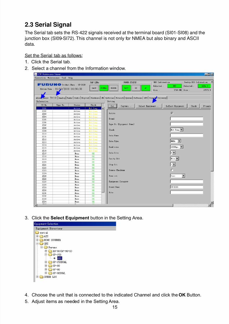
8102019 Ome44376d Vr3000 Mainte Cof26amp3bmol
httpslidepdfcomreaderfullome44376d-vr3000-mainte-cof26amp3bmol 1757
15
23 Serial Signal
The Serial tab sets the RS-422 signals received at the terminal board (SI01-SI08) and the
junction box (SI09-SI72) This channel is not only for NMEA but also binary and ASCII
data
Set the Serial tab as follows1 Click the Serial tab
2 Select a channel from the Information window
3 Click the Select Equipment button in the Setting Area
4 Choose the unit that is connected to the indicated Channel and click the OK Button
5 Adjust items as needed in the Setting Area
8102019 Ome44376d Vr3000 Mainte Cof26amp3bmol
httpslidepdfcomreaderfullome44376d-vr3000-mainte-cof26amp3bmol 1857
16
6 After finishing the settings for one channel click the Set buttonNote Be sure to do this before moving another channel
7 Repeat steps 2-6 to set up each channel
When running Config Management for Tab Settings
1 From the Maintenance menu click VDR Config Management and then Config
2 Click the Upload button to record data to the VDR memory3 Click the Write button to save data to the DRU backup HDD and CF
The buttons in the Setting Area are as followsSet Save edited dataCapture Received data shown in the serial window dialog boxSelect Equipment Select equipment settings (saved to the database) to reflect in
a channelReflect Equipment Save the equipment setting data to the databaseCheck Check all channels OK or NG (No Good) shown in
Information window
Individual Item ExplanationActive Put check in check box to make channel activeBrand Enter brand nameType No (Equipment Name) Set type no (equipment name)Check Do equipment checkData Name Enter data nameData Type Enter data typeBaud Rate Set baud rate (Available for SI01 to SI08)Data Bit Set number of bits (Available for SI01 to SI08)Parity Bit Set parity bit (Available for SI01 to SI08)Stop Bit Set stop bit (Available for SI01 to SI08)Source Checksum Enter checksum for GPS sourceTime out Set time outEquipment Category Set equipment categoryBoard Name Enter board names where channels are presentNote Enter note
Marked Items For easy identification of input source enter Equipment Category Brand
Type No Date and Name
8102019 Ome44376d Vr3000 Mainte Cof26amp3bmol
httpslidepdfcomreaderfullome44376d-vr3000-mainte-cof26amp3bmol 1957
17
24 Analog SignalAnalog signal is input via Junction Box IF-8530 (optional for VR-3000S)Receivable signal ndash10 to +10 V or 4 to 20mA
Connect the analog signal to V and G terminals on the Junction Box When 4 to 20 mAsignal is connected make a short circuit between the V and I input terminals with jumper
wireThe basic procedure for setting up the analog signal is as follows
1 Click the Analog tab
2 Select channel from the Information Area
3 Set detailed information of the selected channel in the Setting Area Refer to thefollowing illustration to enter detailed item information
In the factory settings there is no preset data when the Select Equipment button is
pressed In the case that the setup was completed on another ship and saved usingReflect Equipment import the data by clicking Select Equipment and choosing thesaved data
4 In the following order calibrate the Analog signal
① Click the Calibration button in the Setting Area
② Enter the voltage (or current) value for Calibration Point 1 and thecorresponding engineering value in the left and right boxes
③ Enter values for Calibration Point 2④ Enter unit for the values in Engineering Value Unit
8102019 Ome44376d Vr3000 Mainte Cof26amp3bmol
httpslidepdfcomreaderfullome44376d-vr3000-mainte-cof26amp3bmol 2057
18
In the above image the Engineering Value Unit is set to degrees (deg) TheCalibration Point 1 is -10V corresponding to 0 degrees Calibration Point 2 is10V corresponding to 30 degrees This is set corresponding to the connectedanalog sensor
When the Apply button is clicked the New Engineering Value of 29835Vcorresponding to the input Voltage of 989V is displayed in the bottom fieldWhenever the input value is changed this value also changes Check that theNew Engineering Value is within an appropriate range
Another method is to observe the Voltage (or Current) field in the top field andpress the Hold button of Point 1 when an appropriate value is displaying Dothis again for Point 2
⑤ Click the OK Button
5 When setting is complete click the Set button Be sure to do this before movinganother to channel
6 Repeat steps 1-5 to set up all channels
When using Config Manager with Tabs
1 From the Maintenance menu click VDR Config Management and then Config
2 Click the Upload button to record to VDR memory
3 Click the Write buttons to record to DRU Backup HDD and CF memory
The items in the Setting Area are as shown below Active Put check in check box to make channel activeBrand Enter brand name
Type No Set type no (equipment name)
Check Do equipment checkData Name Enter data nameData Type Analog Data type (0~10V -10~10v 4~20mV)
Sampling Rate Display sampling rateCalibration Active Disable and enable analog calibrationCalibration Point 1 Enter calibration point 1
Calibration Point 1 Value Enter calibration point 1 valueCalibration Point 2 Enter calibration point 2Calibration Point 2 Value Enter calibration point 2 valueEngineering Value Unit Enter engineering value unit
8102019 Ome44376d Vr3000 Mainte Cof26amp3bmol
httpslidepdfcomreaderfullome44376d-vr3000-mainte-cof26amp3bmol 2157
19
Note For -marked boxes values that are set at the Analog Calibration dialog box aredisplayed
Equipment Category Set equipment categoryBoard Name Enter board names where channels are presentNote Enter note
Marked Items For easy identification of input source enter Equipment CategoryBrand Type No Data and Name
25 Digital Signal
Digital signal is connected via Junction Box IF-8530 (optional for VR-3000S) The
receivable signal is 10-32 V for voltage signal or contact signal For voltage signal
connect to A and B input terminals on the Junction Box For contact signal connect to B
and G input terminals on the Junction Box Also make a short-circuit between the 24 and
A input terminals with a jumper wire
To set up the Digital tab
1 Click the Digital tab
2 Select a channel from the Information Area
3 Set up the digital signal from the Setting Area Refer to the following individual item
explanation
In the factory settings there is no preset data when the Select Equipment button is
pressed In the case that the setup was completed on another ship and saved using
Reflect Equipment import the data by clicking Select Equipment and choosing the
saved data
4 When setting Digital Signal to each 64 channel group perform the following
directions1 Click the Calibration button in the setting area
8102019 Ome44376d Vr3000 Mainte Cof26amp3bmol
httpslidepdfcomreaderfullome44376d-vr3000-mainte-cof26amp3bmol 2257
20
2 Check the active column of the channel group being set
3 Enter the status in columns 0 and 1 of that group
4 Click the OK Button
5 When finished setting up click the Set button
6 Repeat steps 2-5 to set up other channels
When using Config Manager with Tabs
1 From the Maintenance menu click VDR Config Management
2 Click the Upload button to record to VDR memory
3 Click the Write buttons to record to DRU Backup HDD and CF memory
The items in the Setting Area are as shown below
Active Put check in check box to make channel activeBrand Enter brand name
Type No Set type no (equipment name)Check Do equipment checkData Name Enter and display data nameContact Type Set contact type NO normal open NC normal closeSampling Rate Display sampling rateCalibration Active Disable and enable digital calibrationActive Status (1) Set status display when (1) is activeActive Status (0) Set status display when (0) is activeEquipment Category Set equipment categoryBoard Name Enter board names where channels are presentNote Enter note
Marked Items For easy identification of input source enter Equipment CategoryBrand Type No Date and Name
8102019 Ome44376d Vr3000 Mainte Cof26amp3bmol
httpslidepdfcomreaderfullome44376d-vr3000-mainte-cof26amp3bmol 2357
21
26 Audio
Microphone and VHF audio settings are performed in the Audio tab
Set the items in the Audio tab as shown below
1 Click the Audio tab
2 Select channel from the Information Area3 Click Select Equipment in the Setting Area
4 Click on the connected device in the indicated channel The setting contents aredisplayed in the Information and Setting Areas
5 If required update the item contents in the Setting Area Refer to the detailed itemexplanation below
6 After completing settings for a channel click the Set buttonNote Be sure to click the Set button before moving to another channel
7 Repeat steps 2-6 to set up other channels
8102019 Ome44376d Vr3000 Mainte Cof26amp3bmol
httpslidepdfcomreaderfullome44376d-vr3000-mainte-cof26amp3bmol 2457
22
When using Config Manager with tabs
1 From the Maintenance menu click VDR Config Management
2 Click the Upload button to record to VDR memory
3 Click the Write buttons to record to DRU Backup HDD and CF memory
MIC testDo the MIC test to check whether audio is received clearly in adequate level or not
1 Click the MIC TEST button in the Setting Area
2 Click the TEST button in the MIC Test dialogue box MIC test results are displayed in
the MIC Test dialogue box
3 Click the Close button to close the dialogue box
Note Not the same recordingplayback function as the previous Web Configuratorsoftware
Continuous MIC TestRun the continuous MIC test as needed accordingly
1 Click the Continuous MIC Test button in the Setting Area2 Set up how many times to perform in the Continuous MIC Test dialogue box and click
the Test button
3 Click the Close button to close the dialogue box
8102019 Ome44376d Vr3000 Mainte Cof26amp3bmol
httpslidepdfcomreaderfullome44376d-vr3000-mainte-cof26amp3bmol 2557
23
Active Put check in check box to make channel activeBrand Enter and display brand nameType No Set type no (equipment name)Check Do equipment checkData Name Enter data nameInput Type Enter input type Sampling Data Bit Displays sampling data bit rate
Sampling Frequency Displays Sampling FrequencyCodec Sets MIC typeMIC Test Active M1M3M5 Put a checkmark when performing MIC Test of M1M3M5MIS Test Active M2M4M6 Put a checkmark when performing MIC Test of M2M4M6 MIC M1M3M5 Position Enter MIC position of MIC M1M3M5MIC M2M4M6 Position Enter MIC position of MIC M2M4M6Threshold Level M1M3M5 Enter MIC test threshold level of MIC M1M3M5Threshold Level M2M4M6 Enter MIC test threshold level of MIC M2M4M6Equipment Category Set equipment categoryBoard Name Enter board names where channels are present
Note Enter note Marked Items For easy identification of input source enter Equipment Category BrandType No Date and Name
8102019 Ome44376d Vr3000 Mainte Cof26amp3bmol
httpslidepdfcomreaderfullome44376d-vr3000-mainte-cof26amp3bmol 2657
24
27 Alarm
Alarm and Alarm Status settings are found in the Alarm tab
The Alarm tab shows the following information about alarms Click the Time Categoryand Name tabs in the title bar to sort
Time Time of alarm
Category Alarm categoryName Name of alarm
Number Alarm number
Status Alarm status
Alarm Search
1 Click the Search button above the Alarm tab The Search dialogue box appears
2 Add a checkmark to any desired search items (multiple items can be selected)
Start Time Display name of alarms generated after a certain time
End Time Display name of alarms generated before a certain time
Name Display information for alarm name entered
8102019 Ome44376d Vr3000 Mainte Cof26amp3bmol
httpslidepdfcomreaderfullome44376d-vr3000-mainte-cof26amp3bmol 2757
25
Number Display information for alarm number entered
Status Display alarm status for alarm name entered
3 In the checked items column input the desired search items
4 Click the Search Button
Close the Search box to cancel a search
Note During a search the upper left Mode changes from Play to Search andDisplay search related information
8102019 Ome44376d Vr3000 Mainte Cof26amp3bmol
httpslidepdfcomreaderfullome44376d-vr3000-mainte-cof26amp3bmol 2857
26
28 Event
Click the items shown below to sort by item selected
Note You can sort the items in ascending order () descending order () and
initialization order (no symbol)
Time Time an event occurred
Category Category of an event
Name Name of an event
Contents1 Display data associated with log
Contents2 Display data associated with log
Event Search
Do the following to search events
1 Click the Search button on the upper right of the Event tab
2 In the dialogue box add a checkmark to desired search items Multiple items can bechecked
Start Time Display name of event generated after a certain time
End Time Display name of event generated before a certain time
Name Display event names entered
Number Display event numbers entered
Status Display event status entered
Enter information about the checked event to search in the character input box
3 Click the Search button
Note The mode changes from Play to Search when performing a search
8102019 Ome44376d Vr3000 Mainte Cof26amp3bmol
httpslidepdfcomreaderfullome44376d-vr3000-mainte-cof26amp3bmol 2957
27
29 Hardware
The Hardware tab provides information about the system hardware
The buttons in the Setting window work as follows
Self Check Status Display status of self check
CPU Display information about the CPU
Memory Size Display memory size
CPU Board Display status of CPU board
Audio Board Display status of Audio board
Serial Board Display status of Serial board
Radar Interface Board Display status of Radar Interface boardNote Enter and display note
Marked items are optional
8102019 Ome44376d Vr3000 Mainte Cof26amp3bmol
httpslidepdfcomreaderfullome44376d-vr3000-mainte-cof26amp3bmol 3057
28
210 JB
Connect the Junction Box to the DCU before turning on the system
The JB tab functions to set up the Junction Box
The basic procedure for setting up the Junction Box is as follows
1 Click the JB tab2 Select a Junction Box from the Information Area
3 Set up the Junction Box from the Setting Area
4 Click the Set button (Be sure to do this before moving to another channel)5 Click the Check button to perform an inspection on all channels In the Information
Area check column either OK or NG (No Good) is displayed
When using Config Manager with Tabs
1 From the Maintenance menu click VDR Config Management
2 Click the Upload button to record to VDR memory
3 Click the Write buttons to record to DRU Backup HDD and CF
The items in the Setting window work as followsActive Put check in check box to make channel activeNo Display Junction Box numberIP Address Display IP address of Junction Box acquired by VDRMAC Address Display MAC address of Junction Box acquired by VDRCheck Enable and disable equipment checkNote Enter note
Marked items are optional
8102019 Ome44376d Vr3000 Mainte Cof26amp3bmol
httpslidepdfcomreaderfullome44376d-vr3000-mainte-cof26amp3bmol 3157
29
211 Life Time
The Life Time tab controls consumable parts
The basic procedure for using the Life Time tab is as follows
1 Click the Life Time tab
2 Select a Type No in the Information Area3 Set up the chosen part from Setting Area
4 Click the Set button
Note Be sure to click the Set button before moving to set up a different Type
The items in the Setting window work as follows
Type No Enter and display type no
Data Name Enter and display data name
Level Set replacement level Legal Exchange Parts or Normal Exchange Parts
Replace Date Enter and display recommended day of replacement
Lifetime Term Not usedNote Enter and display note
The Status column of the Information Area displays as follows
OK The recommended date of replacement shown in the Replace Date
box in the Information window has not passed
Out of Date The date of replacement has passed
None The date of replacement has not been set
8102019 Ome44376d Vr3000 Mainte Cof26amp3bmol
httpslidepdfcomreaderfullome44376d-vr3000-mainte-cof26amp3bmol 3257
30
212 Network
The Network tab sets the system network
The basic procedure for setting up the system network is as follows
1 Click the Network tab
2 Select a port from the Information Area
3 Set up the network from the Setting Area
4 Click the Set button
Note1 Be sure to click the Set button before moving to set up a different Port
Note2 After setting the system network reboot the VDR to apply the settings
The items in the Setting window work as follows
LAN Type Enter LAN type Public LAN or JB LAN
MAC Address Enter MAC address
IP Address Enter IP address
Subnet Mask Enter subnet mask
Gateway Address Enter gateway address
Live Play Multicast Mode (Only JB LAN) Check box to enable live player multicast
mode
Multicast Address (Only Public LAN) Enter and display live player multicast addressNote Enter note
Marked items are optional
8102019 Ome44376d Vr3000 Mainte Cof26amp3bmol
httpslidepdfcomreaderfullome44376d-vr3000-mainte-cof26amp3bmol 3357
31
213 System
The System tab sets system related functions
The basic procedure for using the System tab is as follows
1 Click the System tab
2 Set up the chosen item from the Setting Area
3 Click the Set button
Note Be sure to click the Set button before moving to a different tab
The items in the Setting window work as follows
VDR Type Enter type of VDR
VDR Model Enter model number of VDR
Radar Interface Check Enable and disable checking of the Radar Interface board
Junction Box Count Enter number of junction boxes in system
DRU Flash Count Enter number of DRU flash disks in system Set 1 when DRU
serial no is 5000 and more Set 3 when DRU serial no is less
than 5000
DRU Capacity Display capacity of DRU
Backup HDD Capacity Display capacity of Backup HDD
VDR Config Version Display version no of VDR
VDR Config Date Display the number of hours the VDR settings have
been saved
VDR Config Code Display configuration identity code
Installation Engineer Enter name of the equipment installer
Installation Company Enter name of installers company
8102019 Ome44376d Vr3000 Mainte Cof26amp3bmol
httpslidepdfcomreaderfullome44376d-vr3000-mainte-cof26amp3bmol 3457
32
Installation Date Enter the date of the installation
MIC Test Time Enter the date of the MIC test
Note Enter note Marked items are optional
USB memory logging Do not check Enable
IEEE1394 BUS Error Auto Restart function Not used
IEEE1394 Active Node Count Do not change the default value of 3 (However set to 5
for serial number 5000 or less of DRU)
IEEE1394 Recover Process Limit Count Do not change the default value of 10
DRU Error Auto Restart function Not used
REBOOT DELAY TIME (sec) Do not change the default value of 10
LIMIT REBOOT COUNT Do not change the default value of 10
Live Player Max Connection Count The max number of Live Player V4 that can be
connected simultaneously The default no is two
but a maximum of five can be set here After you
change this option reboot the VDR to apply the
setting Disconnect the cable connected with
Live Player V4 (PC) from the VDR and thenreconnect it
214 Software
The Software tab sets and display software-related operations
The basic procedure for using the Software tab is as follows
1 Click the Software tab
2 Set up the chosen Item from the Setting Area
3 Click the Set button
8102019 Ome44376d Vr3000 Mainte Cof26amp3bmol
httpslidepdfcomreaderfullome44376d-vr3000-mainte-cof26amp3bmol 3557
33
The items in the Setting window work as follows
VDR System Program Display the VDR system program no
Process Version Display the process version
Power Distribution Unit (PDU) Display the version no of the PDU
Operation System Display the version no of the OS
Audio Driver Display the version no of the audio driverRAP Version Enter the version no of the RAP
AP Version Enter the version no of the AP
JB1-8 Boot Program Display the no of the RJB Boot program for Junction Boxes
1 to 8
JB1-8 App Program Display the no of the RJB App program for Junction Boxes
1 to 8
Watch Dog Interval Do not change the default value of 60 (Enter the process
response time A process is repeated if there is no response
within the time interval set here)
Giveup Interval Do not change the default value of 300 (Enter the restart
watch time The restarting of a process is stopped when the
number of times it has been restarted is exceeded within the
interval set here)
Refork Limit Do not change the default value of 10 (Enter the upper limit
for process restart The restarting of a process is stopped
when the number of times it has been restarted exceeds the
Give up Interval)
Note Enter note
Marked Items are optional
8102019 Ome44376d Vr3000 Mainte Cof26amp3bmol
httpslidepdfcomreaderfullome44376d-vr3000-mainte-cof26amp3bmol 3657
34
215 GPS
The GPS tab sets GPS-related parameters
The basic procedure for using the GPS tab is as follows
1 Click the GPS tab
2 Set up the chosen channel from the Information window3 Set up the chosen item in the Setting Area
4 Click the Set button
5 Repeat steps 2-4 to set up each Channel
6 Click the Check button to perform an inspection on all channels In the Information Area check column either OK or NG (No Good) is displayed
The items in the Setting window work as follows
Priority Display priority order
Date and Time SourceShip Position Source Set GPS source channel (serial channel
number for ZDA sentence)
Check Enable and disable checking
GPS Antenna Position From Bow Enter position of GPS antenna from bow
GPS Antenna Position From Stern Enter position of GPS antenna from stern
GPS Antenna Position From Port Enter position of GPS antenna from port
GPS Antenna Position From Starboard Enter position of GPS antenna from starboard
GPS Failure Threshold If the ZDA is input within the set time limit
the system restarts synchronized If not
input within the time limit the system restarts
without synchronization
8102019 Ome44376d Vr3000 Mainte Cof26amp3bmol
httpslidepdfcomreaderfullome44376d-vr3000-mainte-cof26amp3bmol 3757
35
GPS Delay Time by Time Sync Enter minimum time delay for time
synchronization Time synchronization is started
only in the time set here
GPS Difference Interval The time set here is added to the GPS time to
synchronize the system time Leave at the default
0 value setting
GPS Sync Giveup Time If the system receives the GPS time within the
time set the system synchronizes with the time
When not receiving a signal the system displays
an ldquoerror 26rdquo message
ZDA Timeout Enter value (seconds) for ZDA timeout (234 error)
from GPS
Note Enter and display note
Marked Items are optional
216 VesselThe Vessel tab sets and displays own ships information such as name and IMO number
The basic procedure for using the Vessel tab is as follows
1 Click the Vessel tab
2 Set up information in the Setting window
3 Click the Set button (Be sure to do this before moving to another port)
4 From the Maintenance menu click VDR Config Management and then Config5 Click the Write buttons to save data to the DRU backup HDD CF
The buttons in the Setting window works as follows
Vessel Name Enter name of vessel
Vessel IMO Number Enter IMO number of vessel
Vessel Flag Enter flag of vessel
Approval of Authority Enter name of approving authority
Note Enter note
Marked items are optional
8102019 Ome44376d Vr3000 Mainte Cof26amp3bmol
httpslidepdfcomreaderfullome44376d-vr3000-mainte-cof26amp3bmol 3857
36
217 Delivery
The Delivery tab functions to transmit data from the VDR to a PC via Ethernet LAN Do
not use this function during live connection
The basic procedure for using the Delivery tab is as follows
1 Click the Delivery tab
2 Click the Add button to show the Delivery Config window
3 Select protocol from the Protocol drop-down box (Unicast or Multicast)
4 Enter IP address in the IP address input box
5 Enter port number in the port number input box
6 Click the tab of the data to send (Analog Digital or Serial)
7 Select the channel of the data to send
8 If Serial was selected at step 6 select applicable data sentence from the Inactivewindow Click the right arrow to move the data sentence to the Active window
9 Click the OK button to close the Delivery Config window
10 The settings are listed in a table in the Delivery window Check the checkbox in the
Active column and then click the Set button
The buttons in the Setting window works as follows
Set Save edited settings
Add Create new delivery settings
Modify Modify selected delivery settings
Delete Delete selected delivery settings
8102019 Ome44376d Vr3000 Mainte Cof26amp3bmol
httpslidepdfcomreaderfullome44376d-vr3000-mainte-cof26amp3bmol 3957
37
3 How to Back up Configuration DataThis chapter shows how to back up configuration data to various storage media
Configuration data can be opened with Word Pad or any text editor other than Notepad
31 How to Back up Configuration Data to the Startup CompactFlash (CF)
Back up data to the startup CF after setting the VDR Configuration data is created on the
CF as a configini file
Note When the error shown below occurs during the downloading or uploading of
configuration data check the connection of the DRU Backup HDD and CF and then
upload or download the configuration data again
[CONN] Download failed
[CONN] Could not upload config file
If error occurs again re-install the VDR Maintenance Viewer
Do the following to back up data to a CF
1 Set up parameters on the tabs referring to Chapter 2
2 Click the Maintenance menu
3 Select VDR Config Management
4 Click the Upload button
5 A confirmation box appears click the OK button to start uploading to the VDR
6 Click the Write button where the arrow connects between VDR and DRU BackupHDD
7 A confirmation window appears click the OK button to save the configuration data tothe DRU and Backup HDD
8102019 Ome44376d Vr3000 Mainte Cof26amp3bmol
httpslidepdfcomreaderfullome44376d-vr3000-mainte-cof26amp3bmol 4057
38
8 Click the Write button where the arrow connects between the VDR and CF
9 A confirmation window appears click the OK button to save the configuration data tothe startup CF
10 Check that the PC VDR DRU Backup HDD and CF share the same VDR configcode
32 How to Back up Configuration Data to a PC
Configuration data saved to the PC can be edited with Wordpad and shared with other
vessels For future service ease it is recommended to backup configuration data to the
PC and have the data on board the vessel Also it is recommended to upload this data to
Furuno SMS (Service Management System) If unable to upload to Furuno SMS please
contact the Service Center Furuno Japan
To back up configuration data to the PC do as follows
1 Set up parameters on the tabs referring to Chapter 2
2 Click the Maintenance menu
3 Select VDR Config Management
4 Click the Export to button
5 A confirmation window appears click the OK button
6 Select where to save the data enter file name then click the Open button
7 Confirm that back up file is in the location selected
33 How to restore the default settings
Click the Default button on the VDR Config Management window to restore the default
settings of the DRU Backup HDD CF and VDR Maintenance Viewer
8102019 Ome44376d Vr3000 Mainte Cof26amp3bmol
httpslidepdfcomreaderfullome44376d-vr3000-mainte-cof26amp3bmol 4157
39
4 How to Upload Configuration Datafrom a PCThe procedure below shows how to upload configuration from the PC to aVR-3000VR-3000S
1 Click the Maintenance menu
2 Select VDR Config Management
3 Click the Import from button
4 The Open window appears Select configuration data and then click the Open button
5 Click the Upload button to upload data to the VR-3000VR-3000S
6 Click the Write buttons to save data to the DRU backup HDD and CF
8102019 Ome44376d Vr3000 Mainte Cof26amp3bmol
httpslidepdfcomreaderfullome44376d-vr3000-mainte-cof26amp3bmol 4257
40
5 Media ManagementThe media management feature deletes data from recording media initialization the
system etc There are two method LAN connection and Direct connection The Direct
connection takes longer time than the LAN connection Basically use the LAN connection
method
Note Initialization or creation of recording media is not available when Source Select onthe Live Player V4 is selected to Backup HDD
51 Initialization
This section shows how to delete data from the recording media Configuration data is
not deleted After performing the software configuration delete the data from the DRU
and HDD
Do the following to delete data from the DRU (LAN connection)
1 Set the PlaybackCPU switch in the DCU to the CPU position
2 Use an Ethernet cross cable to connect the PC to J14 (DATA) in the DCU (See page5)
3 Open the Tool menu
4 Select Media Management to open the VDR Media Management window
5 Check that IP address shown in the ldquoLAN Connect to IPrdquo in VDR Media Table Area isthe same as the IP address access point
6 Select ldquoLAN Connect to IPrdquo in the VDR Media Table column
8102019 Ome44376d Vr3000 Mainte Cof26amp3bmol
httpslidepdfcomreaderfullome44376d-vr3000-mainte-cof26amp3bmol 4357
41
7 Click the Analyze button A list of recording media connected to the VDR appears
Put a checkmark in the checkbox of the Select column for the DRU in the Name columnNote If there are several flash memories in the DRU all flash memories are shownCheck all flash memories shown
8 Select ldquoDRU Initializerdquo from the Operation dropdown list in the Operation area
10 Click the Run button
Do the following to delete data from the DRU (Direct connection)
1 Start Live Player V4 software
2 Open the Tool menu and select Source Select Select Live from the pull-downmenu
3 Click the Alarm tab and open Alarm History
4 Set the PlaybackCPU switch in the DCU to the Playback position
5 Wait approx 10 minutes and confirm that Alarm 174 occurs on Alarm History of LivePlayer V4
6 Connect an IEEEE1394 cable between J6 in the DCU and the PC
7 Open the Tool menu
8 Select Media Management to show the VDR Media Management window
9 Select Direct in the VDR Media Table column
10 Click the Analyze button A list of recording media connected to the VDR appears
11 Put a checkmark in the checkbox of the Select column for the DRU in the Namecolumn
Note If there are several flash memories in the DRU all flash memories are shownCheck all flash memories shown
12 Select ldquoDRU Initializerdquo from the Operation dropdown list in the Operation area
13 Enter password in the password column
14 Click the RUN button
8102019 Ome44376d Vr3000 Mainte Cof26amp3bmol
httpslidepdfcomreaderfullome44376d-vr3000-mainte-cof26amp3bmol 4457
42
Delete data from the Backup HDD as follows (LAN connection)
1 Set the PlaybackCPU switch in the DCU to the CPU position
2 Check that an Ethernet cross cable is connected between J14 in the DCU and the PC
3 Open the Tool menu
4 Select Media Management to open the VDR Media Management window
5 Check that IP address shown in the LAN Connect to IP in VDR Media Table Area is
the same as the IP address access point6 Select LAN Connect to IP in the VDR Media Table column
7 Click the Analyze button
8 A list of recording media connected to the VDR appears
9 Put a checkmark in the box of the Select column for the Backup HDD in the Namecolumn Select ldquoBackup HDD Initializerdquo from the Operation dropdown list in theOperation area
10 Click the Run button
Delete data from the Backup HDD as follows (Direct connection)
1 Start Live Player V4 software
2 Open the Tool menu and select Source Select Select Live from the pull-downmenu
3 Click the Alarm tab and open Alarm History
4 Set the PlaybackCPU switch in the DCU to the Playback position
5 Wait approx 10 minutes and confirm that Alarm 174 occurs on Alarm History of LivePlayer V4
6 Connect an IEEE1394 cable between J6 in the DCU and the PC
7 Open the Tool menu
8 Select Media Management to open the VDR Media Management window9 Select Direct in the VDR Media Table window
10 Click the Analyze button A list of recording media connected to the VDR appears
11 Put a checkmark in the check box of the Select column for the Backup HDD in theName column Select ldquoBackup HDD Initializerdquo from the Operation dropdown list in theOperation area
12 Enter password
13 Click the Run button
8102019 Ome44376d Vr3000 Mainte Cof26amp3bmol
httpslidepdfcomreaderfullome44376d-vr3000-mainte-cof26amp3bmol 4557
43
52 CreationThe Creation feature initializes recording media
Note1 This feature deletes ALL configuration data Backup all VDR configuration data
Note2 When you initialize medium that is a different format for the DRU or Backup HDDdelete all partitions with the disk management tool of Windows
Note3 When the Creation is failed try again If you can not initialize recording media tryunder condition as shown below
Do the Creation by the direct connection (When the Creation by the LAN
connection is failed)
Delete all partitions of the DRU or Backup HDD with the disk management tool of
Windows to do the Creation
If the Creation is still failed request service to repairreplace the DRU or Backup
HDD
Initialize the DRU as follows (LAN connection)
1 Set the PlaybackCPU switch in the DCU to the CPU position
2 Check that an Ethernet cross cable is connected between J14 in the DCU and the PC
3 Open the Tool menu
4 Select Media Management to open the VDR Media Management window
5 Check that IP address shown in the LAN Connect to IP in VDR Media Table Area isthe same as the IP address access point
6 Check ldquoLAN Connect to IPrdquo in the VDR Media Table column
7 Click the Analyze button A list of recording media connected to the VDR appears
8 Put a checkmark in the box of the Select column for the DRU in the Name column
Select ldquoDRU Creationrdquo from the Operation dropdown list in the Operation area
9 Click the Run button
Initialize the Backup HDD as follows (LAN connection)
1 To format the Backup HDD place a checkmark in the Select column of the listedrecord media in the Name column of the VDR Media Management dialogue box
2 From the Operation drop down list of the Operation area select ldquoBackup HDDCreation (Radar) or ldquoBackup HDD Creationrdquo
Two partition tools are available for the Backup HDD in the Media Management as
below
Backup HDD creation
This tool is used when the number of the SXGA video signal connected to the BackupHDD is the same as the DRU The same partition is created on both DRU and HDD
(1) When two SXGA video signals are recorded onto the HDD while 9-GB DRU isconnected
(2) When an SXGA video signal is recorded onto the HDD while 6-GB DRU isconnected
Backup HDD creation (radar)
This tool is used when two SXGA video signals are recorded onto the HDD with 6-GB
DRU connected The HDD has an area (radar) to record the second radar signal inaddition to the same partition as the DRU This tool cannot be used when 9-GB DRUis connected
3 Press the Run Button
8102019 Ome44376d Vr3000 Mainte Cof26amp3bmol
httpslidepdfcomreaderfullome44376d-vr3000-mainte-cof26amp3bmol 4657
44
Initialize the DRU as follows (Direct connection)
1 Start Live Player V4 software
2 Open the Tool menu and select Source Select Select Live from the pull-downmenu
3 Click the Alarm tab and open Alarm History
4 Set the PlaybackCPU switch in the DCU to the Playback position
5 Wait approx 10 minutes and confirm that Alarm 174 occurs on Alarm History of LivePlayer V4
6 Connect an IEEE1394 cable between J6 in the DCU and the PC
7 Open the Tool menu
8 Select Media Management to open the VDR Media Management window
9 Select Direct in the VDR Media Table window
10 Click the Analyze button A list of recording media connected to the VDR appears
11 Put a checkmark in the box of the Select column for the DRU and the desiredrecording media in the Name column In the Operation dropdown list of the Operationarea select ldquoDRU Creationrdquo
12 Enter password in the password column
13 Click the Run button
Initialize the Backup HDD as follows (Direct Connection)
1 To format the Backup HDD place a checkmark in the Select column of the listedrecord media in the Name column of the VDR Media Management dialogue box
2 From the Operation column of the Operation area select ldquoBackup HDD Creation(Radar) or ldquoBackup HDD Creationrdquo
Backup HDD creation
This tool is used when the number of the SXGA video signal connected to the BackupHDD is the same as the DRU The same partition is created on both DRU and HDD
(1) When two SXGA video signals are recorded onto the HDD while 9-GB DRU is
connected
(2) When an SXGA video signal is recorded onto the HDD while 6-GB DRU is
connected
Backup HDD creation (radar)
This tool is used when two SXGA video signals are recorded onto the HDD with 6-GBDRU connected The HDD has an area (radar) to record the second radar signal inaddition to the same partition as the DRU This tool cannot be used when 9-GB DRUis connected
3 Enter the password in the Password column
4 Press the Run Button
8102019 Ome44376d Vr3000 Mainte Cof26amp3bmol
httpslidepdfcomreaderfullome44376d-vr3000-mainte-cof26amp3bmol 4757
45
53 How to Enable Recording Area on the Backup HDD
This function enables writing over a recording area To prevent falsification of data all
recording areas must be saved otherwise this function is disabled To use this function push
the SAVE button Save the data before doing this procedure
Note Software version 135 or higher can enable writing over a recording area even if
all recording areas are not saved
Recording enable (LAN connection)
1 Set the PlaybackCPU switch in the DCU to the CPU position
2 Check that an Ethernet cross cable is connected between J14 in the DCU and the PC
3 Open the Tool menu
4 Select Media Management to open the VDR Media Management window
5 Check that IP address shown in the ldquoLAN Connect to IPrdquo in VDR Media Table Area isthe same as the IP address access point
6 Select ldquoLAN Connect to IPrdquo in the VDR Media Table column7 Click the Analyze button A list of recording media connected to the VDR appears
8 Put a checkmark in the box of the Select column for the Backup HDD in the Namecolumn
9 Select ldquoBackup HDD Recording Area Enablerdquo from the Operation dropdown list in theOperation area
10 Click the Run button
Recording enable (Direct connection)
1 Start Live Player V4 software
2 Open the Tool menu and select Source Select Select Live from the pull-down menu3 Click the Alarm tab and open Alarm History
4 Set the PlaybackCPU switch in the DCU to the Playback position
5 Wait approx 10 minutes and confirm that Alarm 174 occurs on Alarm History of LivePlayer V4
6 Connect an IEEE1394 cable between J6 in the DCU and the PC
7 Open the Tool menu
8 Select Media Management to open the VDR Media Management window
9 Select Direct in the VDR Media Table window
10 Click the Analyze button A list of recording media connected to the VDR appears11 Put a checkmark in the box of the Select column for the Backup HDD in the Name
column
12 Select ldquoBackup HDD Recording Area Enablerdquo from the Operation dropdown list in theOperation area
13 Enter password
14 Click the Run button
8102019 Ome44376d Vr3000 Mainte Cof26amp3bmol
httpslidepdfcomreaderfullome44376d-vr3000-mainte-cof26amp3bmol 4857
46
6 Other Functions
61 Software Management
The software download feature downloads VDR system software to the PC
To download software
1 Click the Maintenance menu
2 From the Software Management menu click Software Download to show theSoftware Download window
3 Enter the IP address 1000100 in the IP address box in the Update Server area
4 Click the Download Software button
5 The confirmation window appears click the OK button
The Software Backup Execute window shows the results of the download
Software is downloaded to C Program Files VDR Viewer Viewer Backup The software file
name is vdrtar
To Update Software
VDR system program version 16x can update the software with the procedure shownbelow
Note Do not update the file downloaded in procedures above
1 Click the Maintenance menu
2 From the Software Management menu click Software Upload to show the SoftwareUpload area
3 Click the Select button to show the Open window
4 Select update file (vdrtar) and click the Open button
8102019 Ome44376d Vr3000 Mainte Cof26amp3bmol
httpslidepdfcomreaderfullome44376d-vr3000-mainte-cof26amp3bmol 4957
47
5 Check the displayed Software information is correct
6 Enter the IP address 1000100 in the IP address box in the Update Server area
7 Enter password
8 Click the Update button
After the updating is completed the VDR is automatically restarted
Note Click the Restore button on the Software Update window to restore previoussoftware version This feature is available after updating the software
62 Password Management
The password can be changed for a serviceman to access the equipment Contact
FURUNO to get the default password to use during installation
Serviceman password
1 Click the Maintenance menu2 Select Change Serviceman Password from Password Management to show the
Change Serviceman Password window
3 Enter current password in the Old Password box
4 Enter the new password in the New Password box of the Change Password area
5 Enter new password again in the Confirm New Password box
6 Click the OK button
Audio password
The audio password set at the VDR Maintenance Viewer can be removed to enable
audio access without password1 Click the Maintenance menu
2 Select Change Audio Password from Password Management to show the Change Audio Password window
3 The confirmation window appears click the OK button
8102019 Ome44376d Vr3000 Mainte Cof26amp3bmol
httpslidepdfcomreaderfullome44376d-vr3000-mainte-cof26amp3bmol 5057
48
63 Record ComparisonThe integrity of the DRU and Backup HDD recordings can be compared This function isused by the RampD engineer for debugging
Follow the procedure as shown below
1 Click the Maintenance menu2 Select Record Comparison to show the Record Comparison window
The results are shown every 15 seconds in the Record Comparison window
8102019 Ome44376d Vr3000 Mainte Cof26amp3bmol
httpslidepdfcomreaderfullome44376d-vr3000-mainte-cof26amp3bmol 5157
49
64 Software History
This section shows you to save and configure software history (communications record)
How to save software history
Note When the error dialog appears while saving the software history restart the VDR
Maintenance Viewer
1 Click the Maintenance menu
2 Select Software History Collect
3 Click the Select button The Open dialog box appears
4 Select where to save the data then click the Open button
5 Select desired save condition then click the OK buttonNone No savingAt Once Save the software history manually Saving begins as soon as the OK button is clickedPeriodic For debugging Do not use otherwise The intervals are 30 sec 60 secand 120 secAlarm Detection For debugging Do not use otherwise Software history is savedwhen specified alarm is released Enter alarm number
How to configure software communications record
The RampD engineer uses this function for debugging Do not do this procedure unless
required Malfunction can result
1 Click the Maintenance menu
2 Select Software History Config
3 Do the followingProcess Select the type of communications record to save ALL saves allcommunications records
Detail Hide or show detailed information4 Click the Send button
8102019 Ome44376d Vr3000 Mainte Cof26amp3bmol
httpslidepdfcomreaderfullome44376d-vr3000-mainte-cof26amp3bmol 5257
50
65 Easy SetupThis feature sets equipment settings in batch and creates a data file of those settings
Default template The default template is created with the settings entered at installation
1 Click the Maintenance menu
2 Select Easy Setup to show the Template Selection window
3 Select Default Template
4 Click the Start button to show the Easy Setup window
5 Right click the channels (Radar Audio Digital Serial Analog) then select Edit toshow the Equipment Selection window
6 From the Equipment Directory window select equipment connected to the selectedchannel and then click the OK button
7 Repeat steps 5 and 6 to select equipment settings for each channel
8 Click the Save button in the Easy Setup window to show the Save window
9 Select where to save the file and enter file name
10 Click the Save button
8102019 Ome44376d Vr3000 Mainte Cof26amp3bmol
httpslidepdfcomreaderfullome44376d-vr3000-mainte-cof26amp3bmol 5357
51
Specific template Use a file already created
1 Click the Maintenance menu
2 Select Easy Setup to show the Template Selection window
3 Check Specified Template
4 Click the Select button and then select the file to edit
5 Click the Start button to show the Easy Setup window
6 Right click the channels (Radar Audio Digital Serial Analog) then select Edit toshow the Equipment Selection window
7 From the Equipment Directory window select equipment connected to the selectedchannel and then click the OK button
8 Repeat steps 6 and 7 to select equipment settings for each channel
9 Click the Save button in the Easy Setup window to show the Save window
10Select where to save the file and enter file name
11 Click the Save button
66 Equipment Management
This feature controls the import and export of equipment settings
Import data file
Import data files of equipment settings created in Easy Setup etc to the VDR
1 Click the Maintenance menu
2 Select Import from Equipment Management to show the Open window
3 Select the data file to import and click Open
Export data file
Export data files of equipment settings from the VDR to a PC
1 Click the Maintenance menu
2 Select Export from Equipment Management to show the Save window
3 Enter file name
4 Click the Save button
8102019 Ome44376d Vr3000 Mainte Cof26amp3bmol
httpslidepdfcomreaderfullome44376d-vr3000-mainte-cof26amp3bmol 5457
52
67 PC_RAP
This feature enables the same operation of the RAP (Remote Alarm Panel) from a PC
Select PC_RAP from the Tool menu to show the PC_RAP window
The buttons in the PC_RAP window function as shown below
SAVE Stop recording in the area where recording is currently being done
ACK Silence audio alarm
The PC_RAP display shows the following information with LEDs
RAP_LEDs Display the status of LEDs on the RAPSave The Save button blinks yellow when pushed When the 4 memory
areas have data recorded to them the Save button lights orange when
pushed
Normal Lights (green) where there are no unconfirmed or not restored
alarms
Error Flashes (red) for not confirmed alarm Lights (red) for unrestored
alarm
8102019 Ome44376d Vr3000 Mainte Cof26amp3bmol
httpslidepdfcomreaderfullome44376d-vr3000-mainte-cof26amp3bmol 5557
53
Backup HDD Information Display status of backup HDD
Selected Display current recording area and its status in green for
normal operation and in red for abnormal operation
Size Display capacity of backup HDD
Alarm area displays unconfirmed alarms
Time Display time alarm was generatedNumber Display number of alarm
Name Display name of alarm
Pending Alarm displays the unrestored alarms out of confirmed alarms only
Time Display time alarm was generated
Number Display number of alarm
Name Display name of alarm
8102019 Ome44376d Vr3000 Mainte Cof26amp3bmol
httpslidepdfcomreaderfullome44376d-vr3000-mainte-cof26amp3bmol 5657
54
68 Other
Status Monitor
The status monitor feature provides comprehensive data about the status of the VDR
From the menu bar click Toolgt Status Monitor to show the Status Monitor window
The buttons in the Status Monitor window work as shown below
Reload Settings for automatic refreshing of the status monitor
ON Turn automatic refresh OFF
OFF The Status Monitor is refreshed every five seconds
Save Available when Reload ON is selected The contents of the Status Monitor can be
saved to a text fileUpdate Update the Status Monitor display
Close Close the Status Monitor display
8102019 Ome44376d Vr3000 Mainte Cof26amp3bmol
httpslidepdfcomreaderfullome44376d-vr3000-mainte-cof26amp3bmol 5757
VDR Error List
This feature compiles all the errors shown on the RAP for easy reference
Access from MenugtToolgtVDR Error List
The VDR error list contains the following information
NO Display the number of the error
Title Display the name of the error
Detail Display details about the error
Exchange Check
This feature removes the alarms generated when replacing the DRU or backup HDD
Access MenugtToolgtExchange Check select either DRU or Backup HDD and click OK
Reboot
Reboot the VDR
8102019 Ome44376d Vr3000 Mainte Cof26amp3bmol
httpslidepdfcomreaderfullome44376d-vr3000-mainte-cof26amp3bmol 1857
16
6 After finishing the settings for one channel click the Set buttonNote Be sure to do this before moving another channel
7 Repeat steps 2-6 to set up each channel
When running Config Management for Tab Settings
1 From the Maintenance menu click VDR Config Management and then Config
2 Click the Upload button to record data to the VDR memory3 Click the Write button to save data to the DRU backup HDD and CF
The buttons in the Setting Area are as followsSet Save edited dataCapture Received data shown in the serial window dialog boxSelect Equipment Select equipment settings (saved to the database) to reflect in
a channelReflect Equipment Save the equipment setting data to the databaseCheck Check all channels OK or NG (No Good) shown in
Information window
Individual Item ExplanationActive Put check in check box to make channel activeBrand Enter brand nameType No (Equipment Name) Set type no (equipment name)Check Do equipment checkData Name Enter data nameData Type Enter data typeBaud Rate Set baud rate (Available for SI01 to SI08)Data Bit Set number of bits (Available for SI01 to SI08)Parity Bit Set parity bit (Available for SI01 to SI08)Stop Bit Set stop bit (Available for SI01 to SI08)Source Checksum Enter checksum for GPS sourceTime out Set time outEquipment Category Set equipment categoryBoard Name Enter board names where channels are presentNote Enter note
Marked Items For easy identification of input source enter Equipment Category Brand
Type No Date and Name
8102019 Ome44376d Vr3000 Mainte Cof26amp3bmol
httpslidepdfcomreaderfullome44376d-vr3000-mainte-cof26amp3bmol 1957
17
24 Analog SignalAnalog signal is input via Junction Box IF-8530 (optional for VR-3000S)Receivable signal ndash10 to +10 V or 4 to 20mA
Connect the analog signal to V and G terminals on the Junction Box When 4 to 20 mAsignal is connected make a short circuit between the V and I input terminals with jumper
wireThe basic procedure for setting up the analog signal is as follows
1 Click the Analog tab
2 Select channel from the Information Area
3 Set detailed information of the selected channel in the Setting Area Refer to thefollowing illustration to enter detailed item information
In the factory settings there is no preset data when the Select Equipment button is
pressed In the case that the setup was completed on another ship and saved usingReflect Equipment import the data by clicking Select Equipment and choosing thesaved data
4 In the following order calibrate the Analog signal
① Click the Calibration button in the Setting Area
② Enter the voltage (or current) value for Calibration Point 1 and thecorresponding engineering value in the left and right boxes
③ Enter values for Calibration Point 2④ Enter unit for the values in Engineering Value Unit
8102019 Ome44376d Vr3000 Mainte Cof26amp3bmol
httpslidepdfcomreaderfullome44376d-vr3000-mainte-cof26amp3bmol 2057
18
In the above image the Engineering Value Unit is set to degrees (deg) TheCalibration Point 1 is -10V corresponding to 0 degrees Calibration Point 2 is10V corresponding to 30 degrees This is set corresponding to the connectedanalog sensor
When the Apply button is clicked the New Engineering Value of 29835Vcorresponding to the input Voltage of 989V is displayed in the bottom fieldWhenever the input value is changed this value also changes Check that theNew Engineering Value is within an appropriate range
Another method is to observe the Voltage (or Current) field in the top field andpress the Hold button of Point 1 when an appropriate value is displaying Dothis again for Point 2
⑤ Click the OK Button
5 When setting is complete click the Set button Be sure to do this before movinganother to channel
6 Repeat steps 1-5 to set up all channels
When using Config Manager with Tabs
1 From the Maintenance menu click VDR Config Management and then Config
2 Click the Upload button to record to VDR memory
3 Click the Write buttons to record to DRU Backup HDD and CF memory
The items in the Setting Area are as shown below Active Put check in check box to make channel activeBrand Enter brand name
Type No Set type no (equipment name)
Check Do equipment checkData Name Enter data nameData Type Analog Data type (0~10V -10~10v 4~20mV)
Sampling Rate Display sampling rateCalibration Active Disable and enable analog calibrationCalibration Point 1 Enter calibration point 1
Calibration Point 1 Value Enter calibration point 1 valueCalibration Point 2 Enter calibration point 2Calibration Point 2 Value Enter calibration point 2 valueEngineering Value Unit Enter engineering value unit
8102019 Ome44376d Vr3000 Mainte Cof26amp3bmol
httpslidepdfcomreaderfullome44376d-vr3000-mainte-cof26amp3bmol 2157
19
Note For -marked boxes values that are set at the Analog Calibration dialog box aredisplayed
Equipment Category Set equipment categoryBoard Name Enter board names where channels are presentNote Enter note
Marked Items For easy identification of input source enter Equipment CategoryBrand Type No Data and Name
25 Digital Signal
Digital signal is connected via Junction Box IF-8530 (optional for VR-3000S) The
receivable signal is 10-32 V for voltage signal or contact signal For voltage signal
connect to A and B input terminals on the Junction Box For contact signal connect to B
and G input terminals on the Junction Box Also make a short-circuit between the 24 and
A input terminals with a jumper wire
To set up the Digital tab
1 Click the Digital tab
2 Select a channel from the Information Area
3 Set up the digital signal from the Setting Area Refer to the following individual item
explanation
In the factory settings there is no preset data when the Select Equipment button is
pressed In the case that the setup was completed on another ship and saved using
Reflect Equipment import the data by clicking Select Equipment and choosing the
saved data
4 When setting Digital Signal to each 64 channel group perform the following
directions1 Click the Calibration button in the setting area
8102019 Ome44376d Vr3000 Mainte Cof26amp3bmol
httpslidepdfcomreaderfullome44376d-vr3000-mainte-cof26amp3bmol 2257
20
2 Check the active column of the channel group being set
3 Enter the status in columns 0 and 1 of that group
4 Click the OK Button
5 When finished setting up click the Set button
6 Repeat steps 2-5 to set up other channels
When using Config Manager with Tabs
1 From the Maintenance menu click VDR Config Management
2 Click the Upload button to record to VDR memory
3 Click the Write buttons to record to DRU Backup HDD and CF memory
The items in the Setting Area are as shown below
Active Put check in check box to make channel activeBrand Enter brand name
Type No Set type no (equipment name)Check Do equipment checkData Name Enter and display data nameContact Type Set contact type NO normal open NC normal closeSampling Rate Display sampling rateCalibration Active Disable and enable digital calibrationActive Status (1) Set status display when (1) is activeActive Status (0) Set status display when (0) is activeEquipment Category Set equipment categoryBoard Name Enter board names where channels are presentNote Enter note
Marked Items For easy identification of input source enter Equipment CategoryBrand Type No Date and Name
8102019 Ome44376d Vr3000 Mainte Cof26amp3bmol
httpslidepdfcomreaderfullome44376d-vr3000-mainte-cof26amp3bmol 2357
21
26 Audio
Microphone and VHF audio settings are performed in the Audio tab
Set the items in the Audio tab as shown below
1 Click the Audio tab
2 Select channel from the Information Area3 Click Select Equipment in the Setting Area
4 Click on the connected device in the indicated channel The setting contents aredisplayed in the Information and Setting Areas
5 If required update the item contents in the Setting Area Refer to the detailed itemexplanation below
6 After completing settings for a channel click the Set buttonNote Be sure to click the Set button before moving to another channel
7 Repeat steps 2-6 to set up other channels
8102019 Ome44376d Vr3000 Mainte Cof26amp3bmol
httpslidepdfcomreaderfullome44376d-vr3000-mainte-cof26amp3bmol 2457
22
When using Config Manager with tabs
1 From the Maintenance menu click VDR Config Management
2 Click the Upload button to record to VDR memory
3 Click the Write buttons to record to DRU Backup HDD and CF memory
MIC testDo the MIC test to check whether audio is received clearly in adequate level or not
1 Click the MIC TEST button in the Setting Area
2 Click the TEST button in the MIC Test dialogue box MIC test results are displayed in
the MIC Test dialogue box
3 Click the Close button to close the dialogue box
Note Not the same recordingplayback function as the previous Web Configuratorsoftware
Continuous MIC TestRun the continuous MIC test as needed accordingly
1 Click the Continuous MIC Test button in the Setting Area2 Set up how many times to perform in the Continuous MIC Test dialogue box and click
the Test button
3 Click the Close button to close the dialogue box
8102019 Ome44376d Vr3000 Mainte Cof26amp3bmol
httpslidepdfcomreaderfullome44376d-vr3000-mainte-cof26amp3bmol 2557
23
Active Put check in check box to make channel activeBrand Enter and display brand nameType No Set type no (equipment name)Check Do equipment checkData Name Enter data nameInput Type Enter input type Sampling Data Bit Displays sampling data bit rate
Sampling Frequency Displays Sampling FrequencyCodec Sets MIC typeMIC Test Active M1M3M5 Put a checkmark when performing MIC Test of M1M3M5MIS Test Active M2M4M6 Put a checkmark when performing MIC Test of M2M4M6 MIC M1M3M5 Position Enter MIC position of MIC M1M3M5MIC M2M4M6 Position Enter MIC position of MIC M2M4M6Threshold Level M1M3M5 Enter MIC test threshold level of MIC M1M3M5Threshold Level M2M4M6 Enter MIC test threshold level of MIC M2M4M6Equipment Category Set equipment categoryBoard Name Enter board names where channels are present
Note Enter note Marked Items For easy identification of input source enter Equipment Category BrandType No Date and Name
8102019 Ome44376d Vr3000 Mainte Cof26amp3bmol
httpslidepdfcomreaderfullome44376d-vr3000-mainte-cof26amp3bmol 2657
24
27 Alarm
Alarm and Alarm Status settings are found in the Alarm tab
The Alarm tab shows the following information about alarms Click the Time Categoryand Name tabs in the title bar to sort
Time Time of alarm
Category Alarm categoryName Name of alarm
Number Alarm number
Status Alarm status
Alarm Search
1 Click the Search button above the Alarm tab The Search dialogue box appears
2 Add a checkmark to any desired search items (multiple items can be selected)
Start Time Display name of alarms generated after a certain time
End Time Display name of alarms generated before a certain time
Name Display information for alarm name entered
8102019 Ome44376d Vr3000 Mainte Cof26amp3bmol
httpslidepdfcomreaderfullome44376d-vr3000-mainte-cof26amp3bmol 2757
25
Number Display information for alarm number entered
Status Display alarm status for alarm name entered
3 In the checked items column input the desired search items
4 Click the Search Button
Close the Search box to cancel a search
Note During a search the upper left Mode changes from Play to Search andDisplay search related information
8102019 Ome44376d Vr3000 Mainte Cof26amp3bmol
httpslidepdfcomreaderfullome44376d-vr3000-mainte-cof26amp3bmol 2857
26
28 Event
Click the items shown below to sort by item selected
Note You can sort the items in ascending order () descending order () and
initialization order (no symbol)
Time Time an event occurred
Category Category of an event
Name Name of an event
Contents1 Display data associated with log
Contents2 Display data associated with log
Event Search
Do the following to search events
1 Click the Search button on the upper right of the Event tab
2 In the dialogue box add a checkmark to desired search items Multiple items can bechecked
Start Time Display name of event generated after a certain time
End Time Display name of event generated before a certain time
Name Display event names entered
Number Display event numbers entered
Status Display event status entered
Enter information about the checked event to search in the character input box
3 Click the Search button
Note The mode changes from Play to Search when performing a search
8102019 Ome44376d Vr3000 Mainte Cof26amp3bmol
httpslidepdfcomreaderfullome44376d-vr3000-mainte-cof26amp3bmol 2957
27
29 Hardware
The Hardware tab provides information about the system hardware
The buttons in the Setting window work as follows
Self Check Status Display status of self check
CPU Display information about the CPU
Memory Size Display memory size
CPU Board Display status of CPU board
Audio Board Display status of Audio board
Serial Board Display status of Serial board
Radar Interface Board Display status of Radar Interface boardNote Enter and display note
Marked items are optional
8102019 Ome44376d Vr3000 Mainte Cof26amp3bmol
httpslidepdfcomreaderfullome44376d-vr3000-mainte-cof26amp3bmol 3057
28
210 JB
Connect the Junction Box to the DCU before turning on the system
The JB tab functions to set up the Junction Box
The basic procedure for setting up the Junction Box is as follows
1 Click the JB tab2 Select a Junction Box from the Information Area
3 Set up the Junction Box from the Setting Area
4 Click the Set button (Be sure to do this before moving to another channel)5 Click the Check button to perform an inspection on all channels In the Information
Area check column either OK or NG (No Good) is displayed
When using Config Manager with Tabs
1 From the Maintenance menu click VDR Config Management
2 Click the Upload button to record to VDR memory
3 Click the Write buttons to record to DRU Backup HDD and CF
The items in the Setting window work as followsActive Put check in check box to make channel activeNo Display Junction Box numberIP Address Display IP address of Junction Box acquired by VDRMAC Address Display MAC address of Junction Box acquired by VDRCheck Enable and disable equipment checkNote Enter note
Marked items are optional
8102019 Ome44376d Vr3000 Mainte Cof26amp3bmol
httpslidepdfcomreaderfullome44376d-vr3000-mainte-cof26amp3bmol 3157
29
211 Life Time
The Life Time tab controls consumable parts
The basic procedure for using the Life Time tab is as follows
1 Click the Life Time tab
2 Select a Type No in the Information Area3 Set up the chosen part from Setting Area
4 Click the Set button
Note Be sure to click the Set button before moving to set up a different Type
The items in the Setting window work as follows
Type No Enter and display type no
Data Name Enter and display data name
Level Set replacement level Legal Exchange Parts or Normal Exchange Parts
Replace Date Enter and display recommended day of replacement
Lifetime Term Not usedNote Enter and display note
The Status column of the Information Area displays as follows
OK The recommended date of replacement shown in the Replace Date
box in the Information window has not passed
Out of Date The date of replacement has passed
None The date of replacement has not been set
8102019 Ome44376d Vr3000 Mainte Cof26amp3bmol
httpslidepdfcomreaderfullome44376d-vr3000-mainte-cof26amp3bmol 3257
30
212 Network
The Network tab sets the system network
The basic procedure for setting up the system network is as follows
1 Click the Network tab
2 Select a port from the Information Area
3 Set up the network from the Setting Area
4 Click the Set button
Note1 Be sure to click the Set button before moving to set up a different Port
Note2 After setting the system network reboot the VDR to apply the settings
The items in the Setting window work as follows
LAN Type Enter LAN type Public LAN or JB LAN
MAC Address Enter MAC address
IP Address Enter IP address
Subnet Mask Enter subnet mask
Gateway Address Enter gateway address
Live Play Multicast Mode (Only JB LAN) Check box to enable live player multicast
mode
Multicast Address (Only Public LAN) Enter and display live player multicast addressNote Enter note
Marked items are optional
8102019 Ome44376d Vr3000 Mainte Cof26amp3bmol
httpslidepdfcomreaderfullome44376d-vr3000-mainte-cof26amp3bmol 3357
31
213 System
The System tab sets system related functions
The basic procedure for using the System tab is as follows
1 Click the System tab
2 Set up the chosen item from the Setting Area
3 Click the Set button
Note Be sure to click the Set button before moving to a different tab
The items in the Setting window work as follows
VDR Type Enter type of VDR
VDR Model Enter model number of VDR
Radar Interface Check Enable and disable checking of the Radar Interface board
Junction Box Count Enter number of junction boxes in system
DRU Flash Count Enter number of DRU flash disks in system Set 1 when DRU
serial no is 5000 and more Set 3 when DRU serial no is less
than 5000
DRU Capacity Display capacity of DRU
Backup HDD Capacity Display capacity of Backup HDD
VDR Config Version Display version no of VDR
VDR Config Date Display the number of hours the VDR settings have
been saved
VDR Config Code Display configuration identity code
Installation Engineer Enter name of the equipment installer
Installation Company Enter name of installers company
8102019 Ome44376d Vr3000 Mainte Cof26amp3bmol
httpslidepdfcomreaderfullome44376d-vr3000-mainte-cof26amp3bmol 3457
32
Installation Date Enter the date of the installation
MIC Test Time Enter the date of the MIC test
Note Enter note Marked items are optional
USB memory logging Do not check Enable
IEEE1394 BUS Error Auto Restart function Not used
IEEE1394 Active Node Count Do not change the default value of 3 (However set to 5
for serial number 5000 or less of DRU)
IEEE1394 Recover Process Limit Count Do not change the default value of 10
DRU Error Auto Restart function Not used
REBOOT DELAY TIME (sec) Do not change the default value of 10
LIMIT REBOOT COUNT Do not change the default value of 10
Live Player Max Connection Count The max number of Live Player V4 that can be
connected simultaneously The default no is two
but a maximum of five can be set here After you
change this option reboot the VDR to apply the
setting Disconnect the cable connected with
Live Player V4 (PC) from the VDR and thenreconnect it
214 Software
The Software tab sets and display software-related operations
The basic procedure for using the Software tab is as follows
1 Click the Software tab
2 Set up the chosen Item from the Setting Area
3 Click the Set button
8102019 Ome44376d Vr3000 Mainte Cof26amp3bmol
httpslidepdfcomreaderfullome44376d-vr3000-mainte-cof26amp3bmol 3557
33
The items in the Setting window work as follows
VDR System Program Display the VDR system program no
Process Version Display the process version
Power Distribution Unit (PDU) Display the version no of the PDU
Operation System Display the version no of the OS
Audio Driver Display the version no of the audio driverRAP Version Enter the version no of the RAP
AP Version Enter the version no of the AP
JB1-8 Boot Program Display the no of the RJB Boot program for Junction Boxes
1 to 8
JB1-8 App Program Display the no of the RJB App program for Junction Boxes
1 to 8
Watch Dog Interval Do not change the default value of 60 (Enter the process
response time A process is repeated if there is no response
within the time interval set here)
Giveup Interval Do not change the default value of 300 (Enter the restart
watch time The restarting of a process is stopped when the
number of times it has been restarted is exceeded within the
interval set here)
Refork Limit Do not change the default value of 10 (Enter the upper limit
for process restart The restarting of a process is stopped
when the number of times it has been restarted exceeds the
Give up Interval)
Note Enter note
Marked Items are optional
8102019 Ome44376d Vr3000 Mainte Cof26amp3bmol
httpslidepdfcomreaderfullome44376d-vr3000-mainte-cof26amp3bmol 3657
34
215 GPS
The GPS tab sets GPS-related parameters
The basic procedure for using the GPS tab is as follows
1 Click the GPS tab
2 Set up the chosen channel from the Information window3 Set up the chosen item in the Setting Area
4 Click the Set button
5 Repeat steps 2-4 to set up each Channel
6 Click the Check button to perform an inspection on all channels In the Information Area check column either OK or NG (No Good) is displayed
The items in the Setting window work as follows
Priority Display priority order
Date and Time SourceShip Position Source Set GPS source channel (serial channel
number for ZDA sentence)
Check Enable and disable checking
GPS Antenna Position From Bow Enter position of GPS antenna from bow
GPS Antenna Position From Stern Enter position of GPS antenna from stern
GPS Antenna Position From Port Enter position of GPS antenna from port
GPS Antenna Position From Starboard Enter position of GPS antenna from starboard
GPS Failure Threshold If the ZDA is input within the set time limit
the system restarts synchronized If not
input within the time limit the system restarts
without synchronization
8102019 Ome44376d Vr3000 Mainte Cof26amp3bmol
httpslidepdfcomreaderfullome44376d-vr3000-mainte-cof26amp3bmol 3757
35
GPS Delay Time by Time Sync Enter minimum time delay for time
synchronization Time synchronization is started
only in the time set here
GPS Difference Interval The time set here is added to the GPS time to
synchronize the system time Leave at the default
0 value setting
GPS Sync Giveup Time If the system receives the GPS time within the
time set the system synchronizes with the time
When not receiving a signal the system displays
an ldquoerror 26rdquo message
ZDA Timeout Enter value (seconds) for ZDA timeout (234 error)
from GPS
Note Enter and display note
Marked Items are optional
216 VesselThe Vessel tab sets and displays own ships information such as name and IMO number
The basic procedure for using the Vessel tab is as follows
1 Click the Vessel tab
2 Set up information in the Setting window
3 Click the Set button (Be sure to do this before moving to another port)
4 From the Maintenance menu click VDR Config Management and then Config5 Click the Write buttons to save data to the DRU backup HDD CF
The buttons in the Setting window works as follows
Vessel Name Enter name of vessel
Vessel IMO Number Enter IMO number of vessel
Vessel Flag Enter flag of vessel
Approval of Authority Enter name of approving authority
Note Enter note
Marked items are optional
8102019 Ome44376d Vr3000 Mainte Cof26amp3bmol
httpslidepdfcomreaderfullome44376d-vr3000-mainte-cof26amp3bmol 3857
36
217 Delivery
The Delivery tab functions to transmit data from the VDR to a PC via Ethernet LAN Do
not use this function during live connection
The basic procedure for using the Delivery tab is as follows
1 Click the Delivery tab
2 Click the Add button to show the Delivery Config window
3 Select protocol from the Protocol drop-down box (Unicast or Multicast)
4 Enter IP address in the IP address input box
5 Enter port number in the port number input box
6 Click the tab of the data to send (Analog Digital or Serial)
7 Select the channel of the data to send
8 If Serial was selected at step 6 select applicable data sentence from the Inactivewindow Click the right arrow to move the data sentence to the Active window
9 Click the OK button to close the Delivery Config window
10 The settings are listed in a table in the Delivery window Check the checkbox in the
Active column and then click the Set button
The buttons in the Setting window works as follows
Set Save edited settings
Add Create new delivery settings
Modify Modify selected delivery settings
Delete Delete selected delivery settings
8102019 Ome44376d Vr3000 Mainte Cof26amp3bmol
httpslidepdfcomreaderfullome44376d-vr3000-mainte-cof26amp3bmol 3957
37
3 How to Back up Configuration DataThis chapter shows how to back up configuration data to various storage media
Configuration data can be opened with Word Pad or any text editor other than Notepad
31 How to Back up Configuration Data to the Startup CompactFlash (CF)
Back up data to the startup CF after setting the VDR Configuration data is created on the
CF as a configini file
Note When the error shown below occurs during the downloading or uploading of
configuration data check the connection of the DRU Backup HDD and CF and then
upload or download the configuration data again
[CONN] Download failed
[CONN] Could not upload config file
If error occurs again re-install the VDR Maintenance Viewer
Do the following to back up data to a CF
1 Set up parameters on the tabs referring to Chapter 2
2 Click the Maintenance menu
3 Select VDR Config Management
4 Click the Upload button
5 A confirmation box appears click the OK button to start uploading to the VDR
6 Click the Write button where the arrow connects between VDR and DRU BackupHDD
7 A confirmation window appears click the OK button to save the configuration data tothe DRU and Backup HDD
8102019 Ome44376d Vr3000 Mainte Cof26amp3bmol
httpslidepdfcomreaderfullome44376d-vr3000-mainte-cof26amp3bmol 4057
38
8 Click the Write button where the arrow connects between the VDR and CF
9 A confirmation window appears click the OK button to save the configuration data tothe startup CF
10 Check that the PC VDR DRU Backup HDD and CF share the same VDR configcode
32 How to Back up Configuration Data to a PC
Configuration data saved to the PC can be edited with Wordpad and shared with other
vessels For future service ease it is recommended to backup configuration data to the
PC and have the data on board the vessel Also it is recommended to upload this data to
Furuno SMS (Service Management System) If unable to upload to Furuno SMS please
contact the Service Center Furuno Japan
To back up configuration data to the PC do as follows
1 Set up parameters on the tabs referring to Chapter 2
2 Click the Maintenance menu
3 Select VDR Config Management
4 Click the Export to button
5 A confirmation window appears click the OK button
6 Select where to save the data enter file name then click the Open button
7 Confirm that back up file is in the location selected
33 How to restore the default settings
Click the Default button on the VDR Config Management window to restore the default
settings of the DRU Backup HDD CF and VDR Maintenance Viewer
8102019 Ome44376d Vr3000 Mainte Cof26amp3bmol
httpslidepdfcomreaderfullome44376d-vr3000-mainte-cof26amp3bmol 4157
39
4 How to Upload Configuration Datafrom a PCThe procedure below shows how to upload configuration from the PC to aVR-3000VR-3000S
1 Click the Maintenance menu
2 Select VDR Config Management
3 Click the Import from button
4 The Open window appears Select configuration data and then click the Open button
5 Click the Upload button to upload data to the VR-3000VR-3000S
6 Click the Write buttons to save data to the DRU backup HDD and CF
8102019 Ome44376d Vr3000 Mainte Cof26amp3bmol
httpslidepdfcomreaderfullome44376d-vr3000-mainte-cof26amp3bmol 4257
40
5 Media ManagementThe media management feature deletes data from recording media initialization the
system etc There are two method LAN connection and Direct connection The Direct
connection takes longer time than the LAN connection Basically use the LAN connection
method
Note Initialization or creation of recording media is not available when Source Select onthe Live Player V4 is selected to Backup HDD
51 Initialization
This section shows how to delete data from the recording media Configuration data is
not deleted After performing the software configuration delete the data from the DRU
and HDD
Do the following to delete data from the DRU (LAN connection)
1 Set the PlaybackCPU switch in the DCU to the CPU position
2 Use an Ethernet cross cable to connect the PC to J14 (DATA) in the DCU (See page5)
3 Open the Tool menu
4 Select Media Management to open the VDR Media Management window
5 Check that IP address shown in the ldquoLAN Connect to IPrdquo in VDR Media Table Area isthe same as the IP address access point
6 Select ldquoLAN Connect to IPrdquo in the VDR Media Table column
8102019 Ome44376d Vr3000 Mainte Cof26amp3bmol
httpslidepdfcomreaderfullome44376d-vr3000-mainte-cof26amp3bmol 4357
41
7 Click the Analyze button A list of recording media connected to the VDR appears
Put a checkmark in the checkbox of the Select column for the DRU in the Name columnNote If there are several flash memories in the DRU all flash memories are shownCheck all flash memories shown
8 Select ldquoDRU Initializerdquo from the Operation dropdown list in the Operation area
10 Click the Run button
Do the following to delete data from the DRU (Direct connection)
1 Start Live Player V4 software
2 Open the Tool menu and select Source Select Select Live from the pull-downmenu
3 Click the Alarm tab and open Alarm History
4 Set the PlaybackCPU switch in the DCU to the Playback position
5 Wait approx 10 minutes and confirm that Alarm 174 occurs on Alarm History of LivePlayer V4
6 Connect an IEEEE1394 cable between J6 in the DCU and the PC
7 Open the Tool menu
8 Select Media Management to show the VDR Media Management window
9 Select Direct in the VDR Media Table column
10 Click the Analyze button A list of recording media connected to the VDR appears
11 Put a checkmark in the checkbox of the Select column for the DRU in the Namecolumn
Note If there are several flash memories in the DRU all flash memories are shownCheck all flash memories shown
12 Select ldquoDRU Initializerdquo from the Operation dropdown list in the Operation area
13 Enter password in the password column
14 Click the RUN button
8102019 Ome44376d Vr3000 Mainte Cof26amp3bmol
httpslidepdfcomreaderfullome44376d-vr3000-mainte-cof26amp3bmol 4457
42
Delete data from the Backup HDD as follows (LAN connection)
1 Set the PlaybackCPU switch in the DCU to the CPU position
2 Check that an Ethernet cross cable is connected between J14 in the DCU and the PC
3 Open the Tool menu
4 Select Media Management to open the VDR Media Management window
5 Check that IP address shown in the LAN Connect to IP in VDR Media Table Area is
the same as the IP address access point6 Select LAN Connect to IP in the VDR Media Table column
7 Click the Analyze button
8 A list of recording media connected to the VDR appears
9 Put a checkmark in the box of the Select column for the Backup HDD in the Namecolumn Select ldquoBackup HDD Initializerdquo from the Operation dropdown list in theOperation area
10 Click the Run button
Delete data from the Backup HDD as follows (Direct connection)
1 Start Live Player V4 software
2 Open the Tool menu and select Source Select Select Live from the pull-downmenu
3 Click the Alarm tab and open Alarm History
4 Set the PlaybackCPU switch in the DCU to the Playback position
5 Wait approx 10 minutes and confirm that Alarm 174 occurs on Alarm History of LivePlayer V4
6 Connect an IEEE1394 cable between J6 in the DCU and the PC
7 Open the Tool menu
8 Select Media Management to open the VDR Media Management window9 Select Direct in the VDR Media Table window
10 Click the Analyze button A list of recording media connected to the VDR appears
11 Put a checkmark in the check box of the Select column for the Backup HDD in theName column Select ldquoBackup HDD Initializerdquo from the Operation dropdown list in theOperation area
12 Enter password
13 Click the Run button
8102019 Ome44376d Vr3000 Mainte Cof26amp3bmol
httpslidepdfcomreaderfullome44376d-vr3000-mainte-cof26amp3bmol 4557
43
52 CreationThe Creation feature initializes recording media
Note1 This feature deletes ALL configuration data Backup all VDR configuration data
Note2 When you initialize medium that is a different format for the DRU or Backup HDDdelete all partitions with the disk management tool of Windows
Note3 When the Creation is failed try again If you can not initialize recording media tryunder condition as shown below
Do the Creation by the direct connection (When the Creation by the LAN
connection is failed)
Delete all partitions of the DRU or Backup HDD with the disk management tool of
Windows to do the Creation
If the Creation is still failed request service to repairreplace the DRU or Backup
HDD
Initialize the DRU as follows (LAN connection)
1 Set the PlaybackCPU switch in the DCU to the CPU position
2 Check that an Ethernet cross cable is connected between J14 in the DCU and the PC
3 Open the Tool menu
4 Select Media Management to open the VDR Media Management window
5 Check that IP address shown in the LAN Connect to IP in VDR Media Table Area isthe same as the IP address access point
6 Check ldquoLAN Connect to IPrdquo in the VDR Media Table column
7 Click the Analyze button A list of recording media connected to the VDR appears
8 Put a checkmark in the box of the Select column for the DRU in the Name column
Select ldquoDRU Creationrdquo from the Operation dropdown list in the Operation area
9 Click the Run button
Initialize the Backup HDD as follows (LAN connection)
1 To format the Backup HDD place a checkmark in the Select column of the listedrecord media in the Name column of the VDR Media Management dialogue box
2 From the Operation drop down list of the Operation area select ldquoBackup HDDCreation (Radar) or ldquoBackup HDD Creationrdquo
Two partition tools are available for the Backup HDD in the Media Management as
below
Backup HDD creation
This tool is used when the number of the SXGA video signal connected to the BackupHDD is the same as the DRU The same partition is created on both DRU and HDD
(1) When two SXGA video signals are recorded onto the HDD while 9-GB DRU isconnected
(2) When an SXGA video signal is recorded onto the HDD while 6-GB DRU isconnected
Backup HDD creation (radar)
This tool is used when two SXGA video signals are recorded onto the HDD with 6-GB
DRU connected The HDD has an area (radar) to record the second radar signal inaddition to the same partition as the DRU This tool cannot be used when 9-GB DRUis connected
3 Press the Run Button
8102019 Ome44376d Vr3000 Mainte Cof26amp3bmol
httpslidepdfcomreaderfullome44376d-vr3000-mainte-cof26amp3bmol 4657
44
Initialize the DRU as follows (Direct connection)
1 Start Live Player V4 software
2 Open the Tool menu and select Source Select Select Live from the pull-downmenu
3 Click the Alarm tab and open Alarm History
4 Set the PlaybackCPU switch in the DCU to the Playback position
5 Wait approx 10 minutes and confirm that Alarm 174 occurs on Alarm History of LivePlayer V4
6 Connect an IEEE1394 cable between J6 in the DCU and the PC
7 Open the Tool menu
8 Select Media Management to open the VDR Media Management window
9 Select Direct in the VDR Media Table window
10 Click the Analyze button A list of recording media connected to the VDR appears
11 Put a checkmark in the box of the Select column for the DRU and the desiredrecording media in the Name column In the Operation dropdown list of the Operationarea select ldquoDRU Creationrdquo
12 Enter password in the password column
13 Click the Run button
Initialize the Backup HDD as follows (Direct Connection)
1 To format the Backup HDD place a checkmark in the Select column of the listedrecord media in the Name column of the VDR Media Management dialogue box
2 From the Operation column of the Operation area select ldquoBackup HDD Creation(Radar) or ldquoBackup HDD Creationrdquo
Backup HDD creation
This tool is used when the number of the SXGA video signal connected to the BackupHDD is the same as the DRU The same partition is created on both DRU and HDD
(1) When two SXGA video signals are recorded onto the HDD while 9-GB DRU is
connected
(2) When an SXGA video signal is recorded onto the HDD while 6-GB DRU is
connected
Backup HDD creation (radar)
This tool is used when two SXGA video signals are recorded onto the HDD with 6-GBDRU connected The HDD has an area (radar) to record the second radar signal inaddition to the same partition as the DRU This tool cannot be used when 9-GB DRUis connected
3 Enter the password in the Password column
4 Press the Run Button
8102019 Ome44376d Vr3000 Mainte Cof26amp3bmol
httpslidepdfcomreaderfullome44376d-vr3000-mainte-cof26amp3bmol 4757
45
53 How to Enable Recording Area on the Backup HDD
This function enables writing over a recording area To prevent falsification of data all
recording areas must be saved otherwise this function is disabled To use this function push
the SAVE button Save the data before doing this procedure
Note Software version 135 or higher can enable writing over a recording area even if
all recording areas are not saved
Recording enable (LAN connection)
1 Set the PlaybackCPU switch in the DCU to the CPU position
2 Check that an Ethernet cross cable is connected between J14 in the DCU and the PC
3 Open the Tool menu
4 Select Media Management to open the VDR Media Management window
5 Check that IP address shown in the ldquoLAN Connect to IPrdquo in VDR Media Table Area isthe same as the IP address access point
6 Select ldquoLAN Connect to IPrdquo in the VDR Media Table column7 Click the Analyze button A list of recording media connected to the VDR appears
8 Put a checkmark in the box of the Select column for the Backup HDD in the Namecolumn
9 Select ldquoBackup HDD Recording Area Enablerdquo from the Operation dropdown list in theOperation area
10 Click the Run button
Recording enable (Direct connection)
1 Start Live Player V4 software
2 Open the Tool menu and select Source Select Select Live from the pull-down menu3 Click the Alarm tab and open Alarm History
4 Set the PlaybackCPU switch in the DCU to the Playback position
5 Wait approx 10 minutes and confirm that Alarm 174 occurs on Alarm History of LivePlayer V4
6 Connect an IEEE1394 cable between J6 in the DCU and the PC
7 Open the Tool menu
8 Select Media Management to open the VDR Media Management window
9 Select Direct in the VDR Media Table window
10 Click the Analyze button A list of recording media connected to the VDR appears11 Put a checkmark in the box of the Select column for the Backup HDD in the Name
column
12 Select ldquoBackup HDD Recording Area Enablerdquo from the Operation dropdown list in theOperation area
13 Enter password
14 Click the Run button
8102019 Ome44376d Vr3000 Mainte Cof26amp3bmol
httpslidepdfcomreaderfullome44376d-vr3000-mainte-cof26amp3bmol 4857
46
6 Other Functions
61 Software Management
The software download feature downloads VDR system software to the PC
To download software
1 Click the Maintenance menu
2 From the Software Management menu click Software Download to show theSoftware Download window
3 Enter the IP address 1000100 in the IP address box in the Update Server area
4 Click the Download Software button
5 The confirmation window appears click the OK button
The Software Backup Execute window shows the results of the download
Software is downloaded to C Program Files VDR Viewer Viewer Backup The software file
name is vdrtar
To Update Software
VDR system program version 16x can update the software with the procedure shownbelow
Note Do not update the file downloaded in procedures above
1 Click the Maintenance menu
2 From the Software Management menu click Software Upload to show the SoftwareUpload area
3 Click the Select button to show the Open window
4 Select update file (vdrtar) and click the Open button
8102019 Ome44376d Vr3000 Mainte Cof26amp3bmol
httpslidepdfcomreaderfullome44376d-vr3000-mainte-cof26amp3bmol 4957
47
5 Check the displayed Software information is correct
6 Enter the IP address 1000100 in the IP address box in the Update Server area
7 Enter password
8 Click the Update button
After the updating is completed the VDR is automatically restarted
Note Click the Restore button on the Software Update window to restore previoussoftware version This feature is available after updating the software
62 Password Management
The password can be changed for a serviceman to access the equipment Contact
FURUNO to get the default password to use during installation
Serviceman password
1 Click the Maintenance menu2 Select Change Serviceman Password from Password Management to show the
Change Serviceman Password window
3 Enter current password in the Old Password box
4 Enter the new password in the New Password box of the Change Password area
5 Enter new password again in the Confirm New Password box
6 Click the OK button
Audio password
The audio password set at the VDR Maintenance Viewer can be removed to enable
audio access without password1 Click the Maintenance menu
2 Select Change Audio Password from Password Management to show the Change Audio Password window
3 The confirmation window appears click the OK button
8102019 Ome44376d Vr3000 Mainte Cof26amp3bmol
httpslidepdfcomreaderfullome44376d-vr3000-mainte-cof26amp3bmol 5057
48
63 Record ComparisonThe integrity of the DRU and Backup HDD recordings can be compared This function isused by the RampD engineer for debugging
Follow the procedure as shown below
1 Click the Maintenance menu2 Select Record Comparison to show the Record Comparison window
The results are shown every 15 seconds in the Record Comparison window
8102019 Ome44376d Vr3000 Mainte Cof26amp3bmol
httpslidepdfcomreaderfullome44376d-vr3000-mainte-cof26amp3bmol 5157
49
64 Software History
This section shows you to save and configure software history (communications record)
How to save software history
Note When the error dialog appears while saving the software history restart the VDR
Maintenance Viewer
1 Click the Maintenance menu
2 Select Software History Collect
3 Click the Select button The Open dialog box appears
4 Select where to save the data then click the Open button
5 Select desired save condition then click the OK buttonNone No savingAt Once Save the software history manually Saving begins as soon as the OK button is clickedPeriodic For debugging Do not use otherwise The intervals are 30 sec 60 secand 120 secAlarm Detection For debugging Do not use otherwise Software history is savedwhen specified alarm is released Enter alarm number
How to configure software communications record
The RampD engineer uses this function for debugging Do not do this procedure unless
required Malfunction can result
1 Click the Maintenance menu
2 Select Software History Config
3 Do the followingProcess Select the type of communications record to save ALL saves allcommunications records
Detail Hide or show detailed information4 Click the Send button
8102019 Ome44376d Vr3000 Mainte Cof26amp3bmol
httpslidepdfcomreaderfullome44376d-vr3000-mainte-cof26amp3bmol 5257
50
65 Easy SetupThis feature sets equipment settings in batch and creates a data file of those settings
Default template The default template is created with the settings entered at installation
1 Click the Maintenance menu
2 Select Easy Setup to show the Template Selection window
3 Select Default Template
4 Click the Start button to show the Easy Setup window
5 Right click the channels (Radar Audio Digital Serial Analog) then select Edit toshow the Equipment Selection window
6 From the Equipment Directory window select equipment connected to the selectedchannel and then click the OK button
7 Repeat steps 5 and 6 to select equipment settings for each channel
8 Click the Save button in the Easy Setup window to show the Save window
9 Select where to save the file and enter file name
10 Click the Save button
8102019 Ome44376d Vr3000 Mainte Cof26amp3bmol
httpslidepdfcomreaderfullome44376d-vr3000-mainte-cof26amp3bmol 5357
51
Specific template Use a file already created
1 Click the Maintenance menu
2 Select Easy Setup to show the Template Selection window
3 Check Specified Template
4 Click the Select button and then select the file to edit
5 Click the Start button to show the Easy Setup window
6 Right click the channels (Radar Audio Digital Serial Analog) then select Edit toshow the Equipment Selection window
7 From the Equipment Directory window select equipment connected to the selectedchannel and then click the OK button
8 Repeat steps 6 and 7 to select equipment settings for each channel
9 Click the Save button in the Easy Setup window to show the Save window
10Select where to save the file and enter file name
11 Click the Save button
66 Equipment Management
This feature controls the import and export of equipment settings
Import data file
Import data files of equipment settings created in Easy Setup etc to the VDR
1 Click the Maintenance menu
2 Select Import from Equipment Management to show the Open window
3 Select the data file to import and click Open
Export data file
Export data files of equipment settings from the VDR to a PC
1 Click the Maintenance menu
2 Select Export from Equipment Management to show the Save window
3 Enter file name
4 Click the Save button
8102019 Ome44376d Vr3000 Mainte Cof26amp3bmol
httpslidepdfcomreaderfullome44376d-vr3000-mainte-cof26amp3bmol 5457
52
67 PC_RAP
This feature enables the same operation of the RAP (Remote Alarm Panel) from a PC
Select PC_RAP from the Tool menu to show the PC_RAP window
The buttons in the PC_RAP window function as shown below
SAVE Stop recording in the area where recording is currently being done
ACK Silence audio alarm
The PC_RAP display shows the following information with LEDs
RAP_LEDs Display the status of LEDs on the RAPSave The Save button blinks yellow when pushed When the 4 memory
areas have data recorded to them the Save button lights orange when
pushed
Normal Lights (green) where there are no unconfirmed or not restored
alarms
Error Flashes (red) for not confirmed alarm Lights (red) for unrestored
alarm
8102019 Ome44376d Vr3000 Mainte Cof26amp3bmol
httpslidepdfcomreaderfullome44376d-vr3000-mainte-cof26amp3bmol 5557
53
Backup HDD Information Display status of backup HDD
Selected Display current recording area and its status in green for
normal operation and in red for abnormal operation
Size Display capacity of backup HDD
Alarm area displays unconfirmed alarms
Time Display time alarm was generatedNumber Display number of alarm
Name Display name of alarm
Pending Alarm displays the unrestored alarms out of confirmed alarms only
Time Display time alarm was generated
Number Display number of alarm
Name Display name of alarm
8102019 Ome44376d Vr3000 Mainte Cof26amp3bmol
httpslidepdfcomreaderfullome44376d-vr3000-mainte-cof26amp3bmol 5657
54
68 Other
Status Monitor
The status monitor feature provides comprehensive data about the status of the VDR
From the menu bar click Toolgt Status Monitor to show the Status Monitor window
The buttons in the Status Monitor window work as shown below
Reload Settings for automatic refreshing of the status monitor
ON Turn automatic refresh OFF
OFF The Status Monitor is refreshed every five seconds
Save Available when Reload ON is selected The contents of the Status Monitor can be
saved to a text fileUpdate Update the Status Monitor display
Close Close the Status Monitor display
8102019 Ome44376d Vr3000 Mainte Cof26amp3bmol
httpslidepdfcomreaderfullome44376d-vr3000-mainte-cof26amp3bmol 5757
VDR Error List
This feature compiles all the errors shown on the RAP for easy reference
Access from MenugtToolgtVDR Error List
The VDR error list contains the following information
NO Display the number of the error
Title Display the name of the error
Detail Display details about the error
Exchange Check
This feature removes the alarms generated when replacing the DRU or backup HDD
Access MenugtToolgtExchange Check select either DRU or Backup HDD and click OK
Reboot
Reboot the VDR
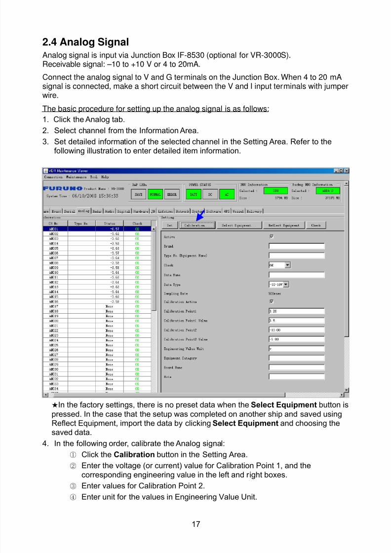
8102019 Ome44376d Vr3000 Mainte Cof26amp3bmol
httpslidepdfcomreaderfullome44376d-vr3000-mainte-cof26amp3bmol 1957
17
24 Analog SignalAnalog signal is input via Junction Box IF-8530 (optional for VR-3000S)Receivable signal ndash10 to +10 V or 4 to 20mA
Connect the analog signal to V and G terminals on the Junction Box When 4 to 20 mAsignal is connected make a short circuit between the V and I input terminals with jumper
wireThe basic procedure for setting up the analog signal is as follows
1 Click the Analog tab
2 Select channel from the Information Area
3 Set detailed information of the selected channel in the Setting Area Refer to thefollowing illustration to enter detailed item information
In the factory settings there is no preset data when the Select Equipment button is
pressed In the case that the setup was completed on another ship and saved usingReflect Equipment import the data by clicking Select Equipment and choosing thesaved data
4 In the following order calibrate the Analog signal
① Click the Calibration button in the Setting Area
② Enter the voltage (or current) value for Calibration Point 1 and thecorresponding engineering value in the left and right boxes
③ Enter values for Calibration Point 2④ Enter unit for the values in Engineering Value Unit
8102019 Ome44376d Vr3000 Mainte Cof26amp3bmol
httpslidepdfcomreaderfullome44376d-vr3000-mainte-cof26amp3bmol 2057
18
In the above image the Engineering Value Unit is set to degrees (deg) TheCalibration Point 1 is -10V corresponding to 0 degrees Calibration Point 2 is10V corresponding to 30 degrees This is set corresponding to the connectedanalog sensor
When the Apply button is clicked the New Engineering Value of 29835Vcorresponding to the input Voltage of 989V is displayed in the bottom fieldWhenever the input value is changed this value also changes Check that theNew Engineering Value is within an appropriate range
Another method is to observe the Voltage (or Current) field in the top field andpress the Hold button of Point 1 when an appropriate value is displaying Dothis again for Point 2
⑤ Click the OK Button
5 When setting is complete click the Set button Be sure to do this before movinganother to channel
6 Repeat steps 1-5 to set up all channels
When using Config Manager with Tabs
1 From the Maintenance menu click VDR Config Management and then Config
2 Click the Upload button to record to VDR memory
3 Click the Write buttons to record to DRU Backup HDD and CF memory
The items in the Setting Area are as shown below Active Put check in check box to make channel activeBrand Enter brand name
Type No Set type no (equipment name)
Check Do equipment checkData Name Enter data nameData Type Analog Data type (0~10V -10~10v 4~20mV)
Sampling Rate Display sampling rateCalibration Active Disable and enable analog calibrationCalibration Point 1 Enter calibration point 1
Calibration Point 1 Value Enter calibration point 1 valueCalibration Point 2 Enter calibration point 2Calibration Point 2 Value Enter calibration point 2 valueEngineering Value Unit Enter engineering value unit
8102019 Ome44376d Vr3000 Mainte Cof26amp3bmol
httpslidepdfcomreaderfullome44376d-vr3000-mainte-cof26amp3bmol 2157
19
Note For -marked boxes values that are set at the Analog Calibration dialog box aredisplayed
Equipment Category Set equipment categoryBoard Name Enter board names where channels are presentNote Enter note
Marked Items For easy identification of input source enter Equipment CategoryBrand Type No Data and Name
25 Digital Signal
Digital signal is connected via Junction Box IF-8530 (optional for VR-3000S) The
receivable signal is 10-32 V for voltage signal or contact signal For voltage signal
connect to A and B input terminals on the Junction Box For contact signal connect to B
and G input terminals on the Junction Box Also make a short-circuit between the 24 and
A input terminals with a jumper wire
To set up the Digital tab
1 Click the Digital tab
2 Select a channel from the Information Area
3 Set up the digital signal from the Setting Area Refer to the following individual item
explanation
In the factory settings there is no preset data when the Select Equipment button is
pressed In the case that the setup was completed on another ship and saved using
Reflect Equipment import the data by clicking Select Equipment and choosing the
saved data
4 When setting Digital Signal to each 64 channel group perform the following
directions1 Click the Calibration button in the setting area
8102019 Ome44376d Vr3000 Mainte Cof26amp3bmol
httpslidepdfcomreaderfullome44376d-vr3000-mainte-cof26amp3bmol 2257
20
2 Check the active column of the channel group being set
3 Enter the status in columns 0 and 1 of that group
4 Click the OK Button
5 When finished setting up click the Set button
6 Repeat steps 2-5 to set up other channels
When using Config Manager with Tabs
1 From the Maintenance menu click VDR Config Management
2 Click the Upload button to record to VDR memory
3 Click the Write buttons to record to DRU Backup HDD and CF memory
The items in the Setting Area are as shown below
Active Put check in check box to make channel activeBrand Enter brand name
Type No Set type no (equipment name)Check Do equipment checkData Name Enter and display data nameContact Type Set contact type NO normal open NC normal closeSampling Rate Display sampling rateCalibration Active Disable and enable digital calibrationActive Status (1) Set status display when (1) is activeActive Status (0) Set status display when (0) is activeEquipment Category Set equipment categoryBoard Name Enter board names where channels are presentNote Enter note
Marked Items For easy identification of input source enter Equipment CategoryBrand Type No Date and Name
8102019 Ome44376d Vr3000 Mainte Cof26amp3bmol
httpslidepdfcomreaderfullome44376d-vr3000-mainte-cof26amp3bmol 2357
21
26 Audio
Microphone and VHF audio settings are performed in the Audio tab
Set the items in the Audio tab as shown below
1 Click the Audio tab
2 Select channel from the Information Area3 Click Select Equipment in the Setting Area
4 Click on the connected device in the indicated channel The setting contents aredisplayed in the Information and Setting Areas
5 If required update the item contents in the Setting Area Refer to the detailed itemexplanation below
6 After completing settings for a channel click the Set buttonNote Be sure to click the Set button before moving to another channel
7 Repeat steps 2-6 to set up other channels
8102019 Ome44376d Vr3000 Mainte Cof26amp3bmol
httpslidepdfcomreaderfullome44376d-vr3000-mainte-cof26amp3bmol 2457
22
When using Config Manager with tabs
1 From the Maintenance menu click VDR Config Management
2 Click the Upload button to record to VDR memory
3 Click the Write buttons to record to DRU Backup HDD and CF memory
MIC testDo the MIC test to check whether audio is received clearly in adequate level or not
1 Click the MIC TEST button in the Setting Area
2 Click the TEST button in the MIC Test dialogue box MIC test results are displayed in
the MIC Test dialogue box
3 Click the Close button to close the dialogue box
Note Not the same recordingplayback function as the previous Web Configuratorsoftware
Continuous MIC TestRun the continuous MIC test as needed accordingly
1 Click the Continuous MIC Test button in the Setting Area2 Set up how many times to perform in the Continuous MIC Test dialogue box and click
the Test button
3 Click the Close button to close the dialogue box
8102019 Ome44376d Vr3000 Mainte Cof26amp3bmol
httpslidepdfcomreaderfullome44376d-vr3000-mainte-cof26amp3bmol 2557
23
Active Put check in check box to make channel activeBrand Enter and display brand nameType No Set type no (equipment name)Check Do equipment checkData Name Enter data nameInput Type Enter input type Sampling Data Bit Displays sampling data bit rate
Sampling Frequency Displays Sampling FrequencyCodec Sets MIC typeMIC Test Active M1M3M5 Put a checkmark when performing MIC Test of M1M3M5MIS Test Active M2M4M6 Put a checkmark when performing MIC Test of M2M4M6 MIC M1M3M5 Position Enter MIC position of MIC M1M3M5MIC M2M4M6 Position Enter MIC position of MIC M2M4M6Threshold Level M1M3M5 Enter MIC test threshold level of MIC M1M3M5Threshold Level M2M4M6 Enter MIC test threshold level of MIC M2M4M6Equipment Category Set equipment categoryBoard Name Enter board names where channels are present
Note Enter note Marked Items For easy identification of input source enter Equipment Category BrandType No Date and Name
8102019 Ome44376d Vr3000 Mainte Cof26amp3bmol
httpslidepdfcomreaderfullome44376d-vr3000-mainte-cof26amp3bmol 2657
24
27 Alarm
Alarm and Alarm Status settings are found in the Alarm tab
The Alarm tab shows the following information about alarms Click the Time Categoryand Name tabs in the title bar to sort
Time Time of alarm
Category Alarm categoryName Name of alarm
Number Alarm number
Status Alarm status
Alarm Search
1 Click the Search button above the Alarm tab The Search dialogue box appears
2 Add a checkmark to any desired search items (multiple items can be selected)
Start Time Display name of alarms generated after a certain time
End Time Display name of alarms generated before a certain time
Name Display information for alarm name entered
8102019 Ome44376d Vr3000 Mainte Cof26amp3bmol
httpslidepdfcomreaderfullome44376d-vr3000-mainte-cof26amp3bmol 2757
25
Number Display information for alarm number entered
Status Display alarm status for alarm name entered
3 In the checked items column input the desired search items
4 Click the Search Button
Close the Search box to cancel a search
Note During a search the upper left Mode changes from Play to Search andDisplay search related information
8102019 Ome44376d Vr3000 Mainte Cof26amp3bmol
httpslidepdfcomreaderfullome44376d-vr3000-mainte-cof26amp3bmol 2857
26
28 Event
Click the items shown below to sort by item selected
Note You can sort the items in ascending order () descending order () and
initialization order (no symbol)
Time Time an event occurred
Category Category of an event
Name Name of an event
Contents1 Display data associated with log
Contents2 Display data associated with log
Event Search
Do the following to search events
1 Click the Search button on the upper right of the Event tab
2 In the dialogue box add a checkmark to desired search items Multiple items can bechecked
Start Time Display name of event generated after a certain time
End Time Display name of event generated before a certain time
Name Display event names entered
Number Display event numbers entered
Status Display event status entered
Enter information about the checked event to search in the character input box
3 Click the Search button
Note The mode changes from Play to Search when performing a search
8102019 Ome44376d Vr3000 Mainte Cof26amp3bmol
httpslidepdfcomreaderfullome44376d-vr3000-mainte-cof26amp3bmol 2957
27
29 Hardware
The Hardware tab provides information about the system hardware
The buttons in the Setting window work as follows
Self Check Status Display status of self check
CPU Display information about the CPU
Memory Size Display memory size
CPU Board Display status of CPU board
Audio Board Display status of Audio board
Serial Board Display status of Serial board
Radar Interface Board Display status of Radar Interface boardNote Enter and display note
Marked items are optional
8102019 Ome44376d Vr3000 Mainte Cof26amp3bmol
httpslidepdfcomreaderfullome44376d-vr3000-mainte-cof26amp3bmol 3057
28
210 JB
Connect the Junction Box to the DCU before turning on the system
The JB tab functions to set up the Junction Box
The basic procedure for setting up the Junction Box is as follows
1 Click the JB tab2 Select a Junction Box from the Information Area
3 Set up the Junction Box from the Setting Area
4 Click the Set button (Be sure to do this before moving to another channel)5 Click the Check button to perform an inspection on all channels In the Information
Area check column either OK or NG (No Good) is displayed
When using Config Manager with Tabs
1 From the Maintenance menu click VDR Config Management
2 Click the Upload button to record to VDR memory
3 Click the Write buttons to record to DRU Backup HDD and CF
The items in the Setting window work as followsActive Put check in check box to make channel activeNo Display Junction Box numberIP Address Display IP address of Junction Box acquired by VDRMAC Address Display MAC address of Junction Box acquired by VDRCheck Enable and disable equipment checkNote Enter note
Marked items are optional
8102019 Ome44376d Vr3000 Mainte Cof26amp3bmol
httpslidepdfcomreaderfullome44376d-vr3000-mainte-cof26amp3bmol 3157
29
211 Life Time
The Life Time tab controls consumable parts
The basic procedure for using the Life Time tab is as follows
1 Click the Life Time tab
2 Select a Type No in the Information Area3 Set up the chosen part from Setting Area
4 Click the Set button
Note Be sure to click the Set button before moving to set up a different Type
The items in the Setting window work as follows
Type No Enter and display type no
Data Name Enter and display data name
Level Set replacement level Legal Exchange Parts or Normal Exchange Parts
Replace Date Enter and display recommended day of replacement
Lifetime Term Not usedNote Enter and display note
The Status column of the Information Area displays as follows
OK The recommended date of replacement shown in the Replace Date
box in the Information window has not passed
Out of Date The date of replacement has passed
None The date of replacement has not been set
8102019 Ome44376d Vr3000 Mainte Cof26amp3bmol
httpslidepdfcomreaderfullome44376d-vr3000-mainte-cof26amp3bmol 3257
30
212 Network
The Network tab sets the system network
The basic procedure for setting up the system network is as follows
1 Click the Network tab
2 Select a port from the Information Area
3 Set up the network from the Setting Area
4 Click the Set button
Note1 Be sure to click the Set button before moving to set up a different Port
Note2 After setting the system network reboot the VDR to apply the settings
The items in the Setting window work as follows
LAN Type Enter LAN type Public LAN or JB LAN
MAC Address Enter MAC address
IP Address Enter IP address
Subnet Mask Enter subnet mask
Gateway Address Enter gateway address
Live Play Multicast Mode (Only JB LAN) Check box to enable live player multicast
mode
Multicast Address (Only Public LAN) Enter and display live player multicast addressNote Enter note
Marked items are optional
8102019 Ome44376d Vr3000 Mainte Cof26amp3bmol
httpslidepdfcomreaderfullome44376d-vr3000-mainte-cof26amp3bmol 3357
31
213 System
The System tab sets system related functions
The basic procedure for using the System tab is as follows
1 Click the System tab
2 Set up the chosen item from the Setting Area
3 Click the Set button
Note Be sure to click the Set button before moving to a different tab
The items in the Setting window work as follows
VDR Type Enter type of VDR
VDR Model Enter model number of VDR
Radar Interface Check Enable and disable checking of the Radar Interface board
Junction Box Count Enter number of junction boxes in system
DRU Flash Count Enter number of DRU flash disks in system Set 1 when DRU
serial no is 5000 and more Set 3 when DRU serial no is less
than 5000
DRU Capacity Display capacity of DRU
Backup HDD Capacity Display capacity of Backup HDD
VDR Config Version Display version no of VDR
VDR Config Date Display the number of hours the VDR settings have
been saved
VDR Config Code Display configuration identity code
Installation Engineer Enter name of the equipment installer
Installation Company Enter name of installers company
8102019 Ome44376d Vr3000 Mainte Cof26amp3bmol
httpslidepdfcomreaderfullome44376d-vr3000-mainte-cof26amp3bmol 3457
32
Installation Date Enter the date of the installation
MIC Test Time Enter the date of the MIC test
Note Enter note Marked items are optional
USB memory logging Do not check Enable
IEEE1394 BUS Error Auto Restart function Not used
IEEE1394 Active Node Count Do not change the default value of 3 (However set to 5
for serial number 5000 or less of DRU)
IEEE1394 Recover Process Limit Count Do not change the default value of 10
DRU Error Auto Restart function Not used
REBOOT DELAY TIME (sec) Do not change the default value of 10
LIMIT REBOOT COUNT Do not change the default value of 10
Live Player Max Connection Count The max number of Live Player V4 that can be
connected simultaneously The default no is two
but a maximum of five can be set here After you
change this option reboot the VDR to apply the
setting Disconnect the cable connected with
Live Player V4 (PC) from the VDR and thenreconnect it
214 Software
The Software tab sets and display software-related operations
The basic procedure for using the Software tab is as follows
1 Click the Software tab
2 Set up the chosen Item from the Setting Area
3 Click the Set button
8102019 Ome44376d Vr3000 Mainte Cof26amp3bmol
httpslidepdfcomreaderfullome44376d-vr3000-mainte-cof26amp3bmol 3557
33
The items in the Setting window work as follows
VDR System Program Display the VDR system program no
Process Version Display the process version
Power Distribution Unit (PDU) Display the version no of the PDU
Operation System Display the version no of the OS
Audio Driver Display the version no of the audio driverRAP Version Enter the version no of the RAP
AP Version Enter the version no of the AP
JB1-8 Boot Program Display the no of the RJB Boot program for Junction Boxes
1 to 8
JB1-8 App Program Display the no of the RJB App program for Junction Boxes
1 to 8
Watch Dog Interval Do not change the default value of 60 (Enter the process
response time A process is repeated if there is no response
within the time interval set here)
Giveup Interval Do not change the default value of 300 (Enter the restart
watch time The restarting of a process is stopped when the
number of times it has been restarted is exceeded within the
interval set here)
Refork Limit Do not change the default value of 10 (Enter the upper limit
for process restart The restarting of a process is stopped
when the number of times it has been restarted exceeds the
Give up Interval)
Note Enter note
Marked Items are optional
8102019 Ome44376d Vr3000 Mainte Cof26amp3bmol
httpslidepdfcomreaderfullome44376d-vr3000-mainte-cof26amp3bmol 3657
34
215 GPS
The GPS tab sets GPS-related parameters
The basic procedure for using the GPS tab is as follows
1 Click the GPS tab
2 Set up the chosen channel from the Information window3 Set up the chosen item in the Setting Area
4 Click the Set button
5 Repeat steps 2-4 to set up each Channel
6 Click the Check button to perform an inspection on all channels In the Information Area check column either OK or NG (No Good) is displayed
The items in the Setting window work as follows
Priority Display priority order
Date and Time SourceShip Position Source Set GPS source channel (serial channel
number for ZDA sentence)
Check Enable and disable checking
GPS Antenna Position From Bow Enter position of GPS antenna from bow
GPS Antenna Position From Stern Enter position of GPS antenna from stern
GPS Antenna Position From Port Enter position of GPS antenna from port
GPS Antenna Position From Starboard Enter position of GPS antenna from starboard
GPS Failure Threshold If the ZDA is input within the set time limit
the system restarts synchronized If not
input within the time limit the system restarts
without synchronization
8102019 Ome44376d Vr3000 Mainte Cof26amp3bmol
httpslidepdfcomreaderfullome44376d-vr3000-mainte-cof26amp3bmol 3757
35
GPS Delay Time by Time Sync Enter minimum time delay for time
synchronization Time synchronization is started
only in the time set here
GPS Difference Interval The time set here is added to the GPS time to
synchronize the system time Leave at the default
0 value setting
GPS Sync Giveup Time If the system receives the GPS time within the
time set the system synchronizes with the time
When not receiving a signal the system displays
an ldquoerror 26rdquo message
ZDA Timeout Enter value (seconds) for ZDA timeout (234 error)
from GPS
Note Enter and display note
Marked Items are optional
216 VesselThe Vessel tab sets and displays own ships information such as name and IMO number
The basic procedure for using the Vessel tab is as follows
1 Click the Vessel tab
2 Set up information in the Setting window
3 Click the Set button (Be sure to do this before moving to another port)
4 From the Maintenance menu click VDR Config Management and then Config5 Click the Write buttons to save data to the DRU backup HDD CF
The buttons in the Setting window works as follows
Vessel Name Enter name of vessel
Vessel IMO Number Enter IMO number of vessel
Vessel Flag Enter flag of vessel
Approval of Authority Enter name of approving authority
Note Enter note
Marked items are optional
8102019 Ome44376d Vr3000 Mainte Cof26amp3bmol
httpslidepdfcomreaderfullome44376d-vr3000-mainte-cof26amp3bmol 3857
36
217 Delivery
The Delivery tab functions to transmit data from the VDR to a PC via Ethernet LAN Do
not use this function during live connection
The basic procedure for using the Delivery tab is as follows
1 Click the Delivery tab
2 Click the Add button to show the Delivery Config window
3 Select protocol from the Protocol drop-down box (Unicast or Multicast)
4 Enter IP address in the IP address input box
5 Enter port number in the port number input box
6 Click the tab of the data to send (Analog Digital or Serial)
7 Select the channel of the data to send
8 If Serial was selected at step 6 select applicable data sentence from the Inactivewindow Click the right arrow to move the data sentence to the Active window
9 Click the OK button to close the Delivery Config window
10 The settings are listed in a table in the Delivery window Check the checkbox in the
Active column and then click the Set button
The buttons in the Setting window works as follows
Set Save edited settings
Add Create new delivery settings
Modify Modify selected delivery settings
Delete Delete selected delivery settings
8102019 Ome44376d Vr3000 Mainte Cof26amp3bmol
httpslidepdfcomreaderfullome44376d-vr3000-mainte-cof26amp3bmol 3957
37
3 How to Back up Configuration DataThis chapter shows how to back up configuration data to various storage media
Configuration data can be opened with Word Pad or any text editor other than Notepad
31 How to Back up Configuration Data to the Startup CompactFlash (CF)
Back up data to the startup CF after setting the VDR Configuration data is created on the
CF as a configini file
Note When the error shown below occurs during the downloading or uploading of
configuration data check the connection of the DRU Backup HDD and CF and then
upload or download the configuration data again
[CONN] Download failed
[CONN] Could not upload config file
If error occurs again re-install the VDR Maintenance Viewer
Do the following to back up data to a CF
1 Set up parameters on the tabs referring to Chapter 2
2 Click the Maintenance menu
3 Select VDR Config Management
4 Click the Upload button
5 A confirmation box appears click the OK button to start uploading to the VDR
6 Click the Write button where the arrow connects between VDR and DRU BackupHDD
7 A confirmation window appears click the OK button to save the configuration data tothe DRU and Backup HDD
8102019 Ome44376d Vr3000 Mainte Cof26amp3bmol
httpslidepdfcomreaderfullome44376d-vr3000-mainte-cof26amp3bmol 4057
38
8 Click the Write button where the arrow connects between the VDR and CF
9 A confirmation window appears click the OK button to save the configuration data tothe startup CF
10 Check that the PC VDR DRU Backup HDD and CF share the same VDR configcode
32 How to Back up Configuration Data to a PC
Configuration data saved to the PC can be edited with Wordpad and shared with other
vessels For future service ease it is recommended to backup configuration data to the
PC and have the data on board the vessel Also it is recommended to upload this data to
Furuno SMS (Service Management System) If unable to upload to Furuno SMS please
contact the Service Center Furuno Japan
To back up configuration data to the PC do as follows
1 Set up parameters on the tabs referring to Chapter 2
2 Click the Maintenance menu
3 Select VDR Config Management
4 Click the Export to button
5 A confirmation window appears click the OK button
6 Select where to save the data enter file name then click the Open button
7 Confirm that back up file is in the location selected
33 How to restore the default settings
Click the Default button on the VDR Config Management window to restore the default
settings of the DRU Backup HDD CF and VDR Maintenance Viewer
8102019 Ome44376d Vr3000 Mainte Cof26amp3bmol
httpslidepdfcomreaderfullome44376d-vr3000-mainte-cof26amp3bmol 4157
39
4 How to Upload Configuration Datafrom a PCThe procedure below shows how to upload configuration from the PC to aVR-3000VR-3000S
1 Click the Maintenance menu
2 Select VDR Config Management
3 Click the Import from button
4 The Open window appears Select configuration data and then click the Open button
5 Click the Upload button to upload data to the VR-3000VR-3000S
6 Click the Write buttons to save data to the DRU backup HDD and CF
8102019 Ome44376d Vr3000 Mainte Cof26amp3bmol
httpslidepdfcomreaderfullome44376d-vr3000-mainte-cof26amp3bmol 4257
40
5 Media ManagementThe media management feature deletes data from recording media initialization the
system etc There are two method LAN connection and Direct connection The Direct
connection takes longer time than the LAN connection Basically use the LAN connection
method
Note Initialization or creation of recording media is not available when Source Select onthe Live Player V4 is selected to Backup HDD
51 Initialization
This section shows how to delete data from the recording media Configuration data is
not deleted After performing the software configuration delete the data from the DRU
and HDD
Do the following to delete data from the DRU (LAN connection)
1 Set the PlaybackCPU switch in the DCU to the CPU position
2 Use an Ethernet cross cable to connect the PC to J14 (DATA) in the DCU (See page5)
3 Open the Tool menu
4 Select Media Management to open the VDR Media Management window
5 Check that IP address shown in the ldquoLAN Connect to IPrdquo in VDR Media Table Area isthe same as the IP address access point
6 Select ldquoLAN Connect to IPrdquo in the VDR Media Table column
8102019 Ome44376d Vr3000 Mainte Cof26amp3bmol
httpslidepdfcomreaderfullome44376d-vr3000-mainte-cof26amp3bmol 4357
41
7 Click the Analyze button A list of recording media connected to the VDR appears
Put a checkmark in the checkbox of the Select column for the DRU in the Name columnNote If there are several flash memories in the DRU all flash memories are shownCheck all flash memories shown
8 Select ldquoDRU Initializerdquo from the Operation dropdown list in the Operation area
10 Click the Run button
Do the following to delete data from the DRU (Direct connection)
1 Start Live Player V4 software
2 Open the Tool menu and select Source Select Select Live from the pull-downmenu
3 Click the Alarm tab and open Alarm History
4 Set the PlaybackCPU switch in the DCU to the Playback position
5 Wait approx 10 minutes and confirm that Alarm 174 occurs on Alarm History of LivePlayer V4
6 Connect an IEEEE1394 cable between J6 in the DCU and the PC
7 Open the Tool menu
8 Select Media Management to show the VDR Media Management window
9 Select Direct in the VDR Media Table column
10 Click the Analyze button A list of recording media connected to the VDR appears
11 Put a checkmark in the checkbox of the Select column for the DRU in the Namecolumn
Note If there are several flash memories in the DRU all flash memories are shownCheck all flash memories shown
12 Select ldquoDRU Initializerdquo from the Operation dropdown list in the Operation area
13 Enter password in the password column
14 Click the RUN button
8102019 Ome44376d Vr3000 Mainte Cof26amp3bmol
httpslidepdfcomreaderfullome44376d-vr3000-mainte-cof26amp3bmol 4457
42
Delete data from the Backup HDD as follows (LAN connection)
1 Set the PlaybackCPU switch in the DCU to the CPU position
2 Check that an Ethernet cross cable is connected between J14 in the DCU and the PC
3 Open the Tool menu
4 Select Media Management to open the VDR Media Management window
5 Check that IP address shown in the LAN Connect to IP in VDR Media Table Area is
the same as the IP address access point6 Select LAN Connect to IP in the VDR Media Table column
7 Click the Analyze button
8 A list of recording media connected to the VDR appears
9 Put a checkmark in the box of the Select column for the Backup HDD in the Namecolumn Select ldquoBackup HDD Initializerdquo from the Operation dropdown list in theOperation area
10 Click the Run button
Delete data from the Backup HDD as follows (Direct connection)
1 Start Live Player V4 software
2 Open the Tool menu and select Source Select Select Live from the pull-downmenu
3 Click the Alarm tab and open Alarm History
4 Set the PlaybackCPU switch in the DCU to the Playback position
5 Wait approx 10 minutes and confirm that Alarm 174 occurs on Alarm History of LivePlayer V4
6 Connect an IEEE1394 cable between J6 in the DCU and the PC
7 Open the Tool menu
8 Select Media Management to open the VDR Media Management window9 Select Direct in the VDR Media Table window
10 Click the Analyze button A list of recording media connected to the VDR appears
11 Put a checkmark in the check box of the Select column for the Backup HDD in theName column Select ldquoBackup HDD Initializerdquo from the Operation dropdown list in theOperation area
12 Enter password
13 Click the Run button
8102019 Ome44376d Vr3000 Mainte Cof26amp3bmol
httpslidepdfcomreaderfullome44376d-vr3000-mainte-cof26amp3bmol 4557
43
52 CreationThe Creation feature initializes recording media
Note1 This feature deletes ALL configuration data Backup all VDR configuration data
Note2 When you initialize medium that is a different format for the DRU or Backup HDDdelete all partitions with the disk management tool of Windows
Note3 When the Creation is failed try again If you can not initialize recording media tryunder condition as shown below
Do the Creation by the direct connection (When the Creation by the LAN
connection is failed)
Delete all partitions of the DRU or Backup HDD with the disk management tool of
Windows to do the Creation
If the Creation is still failed request service to repairreplace the DRU or Backup
HDD
Initialize the DRU as follows (LAN connection)
1 Set the PlaybackCPU switch in the DCU to the CPU position
2 Check that an Ethernet cross cable is connected between J14 in the DCU and the PC
3 Open the Tool menu
4 Select Media Management to open the VDR Media Management window
5 Check that IP address shown in the LAN Connect to IP in VDR Media Table Area isthe same as the IP address access point
6 Check ldquoLAN Connect to IPrdquo in the VDR Media Table column
7 Click the Analyze button A list of recording media connected to the VDR appears
8 Put a checkmark in the box of the Select column for the DRU in the Name column
Select ldquoDRU Creationrdquo from the Operation dropdown list in the Operation area
9 Click the Run button
Initialize the Backup HDD as follows (LAN connection)
1 To format the Backup HDD place a checkmark in the Select column of the listedrecord media in the Name column of the VDR Media Management dialogue box
2 From the Operation drop down list of the Operation area select ldquoBackup HDDCreation (Radar) or ldquoBackup HDD Creationrdquo
Two partition tools are available for the Backup HDD in the Media Management as
below
Backup HDD creation
This tool is used when the number of the SXGA video signal connected to the BackupHDD is the same as the DRU The same partition is created on both DRU and HDD
(1) When two SXGA video signals are recorded onto the HDD while 9-GB DRU isconnected
(2) When an SXGA video signal is recorded onto the HDD while 6-GB DRU isconnected
Backup HDD creation (radar)
This tool is used when two SXGA video signals are recorded onto the HDD with 6-GB
DRU connected The HDD has an area (radar) to record the second radar signal inaddition to the same partition as the DRU This tool cannot be used when 9-GB DRUis connected
3 Press the Run Button
8102019 Ome44376d Vr3000 Mainte Cof26amp3bmol
httpslidepdfcomreaderfullome44376d-vr3000-mainte-cof26amp3bmol 4657
44
Initialize the DRU as follows (Direct connection)
1 Start Live Player V4 software
2 Open the Tool menu and select Source Select Select Live from the pull-downmenu
3 Click the Alarm tab and open Alarm History
4 Set the PlaybackCPU switch in the DCU to the Playback position
5 Wait approx 10 minutes and confirm that Alarm 174 occurs on Alarm History of LivePlayer V4
6 Connect an IEEE1394 cable between J6 in the DCU and the PC
7 Open the Tool menu
8 Select Media Management to open the VDR Media Management window
9 Select Direct in the VDR Media Table window
10 Click the Analyze button A list of recording media connected to the VDR appears
11 Put a checkmark in the box of the Select column for the DRU and the desiredrecording media in the Name column In the Operation dropdown list of the Operationarea select ldquoDRU Creationrdquo
12 Enter password in the password column
13 Click the Run button
Initialize the Backup HDD as follows (Direct Connection)
1 To format the Backup HDD place a checkmark in the Select column of the listedrecord media in the Name column of the VDR Media Management dialogue box
2 From the Operation column of the Operation area select ldquoBackup HDD Creation(Radar) or ldquoBackup HDD Creationrdquo
Backup HDD creation
This tool is used when the number of the SXGA video signal connected to the BackupHDD is the same as the DRU The same partition is created on both DRU and HDD
(1) When two SXGA video signals are recorded onto the HDD while 9-GB DRU is
connected
(2) When an SXGA video signal is recorded onto the HDD while 6-GB DRU is
connected
Backup HDD creation (radar)
This tool is used when two SXGA video signals are recorded onto the HDD with 6-GBDRU connected The HDD has an area (radar) to record the second radar signal inaddition to the same partition as the DRU This tool cannot be used when 9-GB DRUis connected
3 Enter the password in the Password column
4 Press the Run Button
8102019 Ome44376d Vr3000 Mainte Cof26amp3bmol
httpslidepdfcomreaderfullome44376d-vr3000-mainte-cof26amp3bmol 4757
45
53 How to Enable Recording Area on the Backup HDD
This function enables writing over a recording area To prevent falsification of data all
recording areas must be saved otherwise this function is disabled To use this function push
the SAVE button Save the data before doing this procedure
Note Software version 135 or higher can enable writing over a recording area even if
all recording areas are not saved
Recording enable (LAN connection)
1 Set the PlaybackCPU switch in the DCU to the CPU position
2 Check that an Ethernet cross cable is connected between J14 in the DCU and the PC
3 Open the Tool menu
4 Select Media Management to open the VDR Media Management window
5 Check that IP address shown in the ldquoLAN Connect to IPrdquo in VDR Media Table Area isthe same as the IP address access point
6 Select ldquoLAN Connect to IPrdquo in the VDR Media Table column7 Click the Analyze button A list of recording media connected to the VDR appears
8 Put a checkmark in the box of the Select column for the Backup HDD in the Namecolumn
9 Select ldquoBackup HDD Recording Area Enablerdquo from the Operation dropdown list in theOperation area
10 Click the Run button
Recording enable (Direct connection)
1 Start Live Player V4 software
2 Open the Tool menu and select Source Select Select Live from the pull-down menu3 Click the Alarm tab and open Alarm History
4 Set the PlaybackCPU switch in the DCU to the Playback position
5 Wait approx 10 minutes and confirm that Alarm 174 occurs on Alarm History of LivePlayer V4
6 Connect an IEEE1394 cable between J6 in the DCU and the PC
7 Open the Tool menu
8 Select Media Management to open the VDR Media Management window
9 Select Direct in the VDR Media Table window
10 Click the Analyze button A list of recording media connected to the VDR appears11 Put a checkmark in the box of the Select column for the Backup HDD in the Name
column
12 Select ldquoBackup HDD Recording Area Enablerdquo from the Operation dropdown list in theOperation area
13 Enter password
14 Click the Run button
8102019 Ome44376d Vr3000 Mainte Cof26amp3bmol
httpslidepdfcomreaderfullome44376d-vr3000-mainte-cof26amp3bmol 4857
46
6 Other Functions
61 Software Management
The software download feature downloads VDR system software to the PC
To download software
1 Click the Maintenance menu
2 From the Software Management menu click Software Download to show theSoftware Download window
3 Enter the IP address 1000100 in the IP address box in the Update Server area
4 Click the Download Software button
5 The confirmation window appears click the OK button
The Software Backup Execute window shows the results of the download
Software is downloaded to C Program Files VDR Viewer Viewer Backup The software file
name is vdrtar
To Update Software
VDR system program version 16x can update the software with the procedure shownbelow
Note Do not update the file downloaded in procedures above
1 Click the Maintenance menu
2 From the Software Management menu click Software Upload to show the SoftwareUpload area
3 Click the Select button to show the Open window
4 Select update file (vdrtar) and click the Open button
8102019 Ome44376d Vr3000 Mainte Cof26amp3bmol
httpslidepdfcomreaderfullome44376d-vr3000-mainte-cof26amp3bmol 4957
47
5 Check the displayed Software information is correct
6 Enter the IP address 1000100 in the IP address box in the Update Server area
7 Enter password
8 Click the Update button
After the updating is completed the VDR is automatically restarted
Note Click the Restore button on the Software Update window to restore previoussoftware version This feature is available after updating the software
62 Password Management
The password can be changed for a serviceman to access the equipment Contact
FURUNO to get the default password to use during installation
Serviceman password
1 Click the Maintenance menu2 Select Change Serviceman Password from Password Management to show the
Change Serviceman Password window
3 Enter current password in the Old Password box
4 Enter the new password in the New Password box of the Change Password area
5 Enter new password again in the Confirm New Password box
6 Click the OK button
Audio password
The audio password set at the VDR Maintenance Viewer can be removed to enable
audio access without password1 Click the Maintenance menu
2 Select Change Audio Password from Password Management to show the Change Audio Password window
3 The confirmation window appears click the OK button
8102019 Ome44376d Vr3000 Mainte Cof26amp3bmol
httpslidepdfcomreaderfullome44376d-vr3000-mainte-cof26amp3bmol 5057
48
63 Record ComparisonThe integrity of the DRU and Backup HDD recordings can be compared This function isused by the RampD engineer for debugging
Follow the procedure as shown below
1 Click the Maintenance menu2 Select Record Comparison to show the Record Comparison window
The results are shown every 15 seconds in the Record Comparison window
8102019 Ome44376d Vr3000 Mainte Cof26amp3bmol
httpslidepdfcomreaderfullome44376d-vr3000-mainte-cof26amp3bmol 5157
49
64 Software History
This section shows you to save and configure software history (communications record)
How to save software history
Note When the error dialog appears while saving the software history restart the VDR
Maintenance Viewer
1 Click the Maintenance menu
2 Select Software History Collect
3 Click the Select button The Open dialog box appears
4 Select where to save the data then click the Open button
5 Select desired save condition then click the OK buttonNone No savingAt Once Save the software history manually Saving begins as soon as the OK button is clickedPeriodic For debugging Do not use otherwise The intervals are 30 sec 60 secand 120 secAlarm Detection For debugging Do not use otherwise Software history is savedwhen specified alarm is released Enter alarm number
How to configure software communications record
The RampD engineer uses this function for debugging Do not do this procedure unless
required Malfunction can result
1 Click the Maintenance menu
2 Select Software History Config
3 Do the followingProcess Select the type of communications record to save ALL saves allcommunications records
Detail Hide or show detailed information4 Click the Send button
8102019 Ome44376d Vr3000 Mainte Cof26amp3bmol
httpslidepdfcomreaderfullome44376d-vr3000-mainte-cof26amp3bmol 5257
50
65 Easy SetupThis feature sets equipment settings in batch and creates a data file of those settings
Default template The default template is created with the settings entered at installation
1 Click the Maintenance menu
2 Select Easy Setup to show the Template Selection window
3 Select Default Template
4 Click the Start button to show the Easy Setup window
5 Right click the channels (Radar Audio Digital Serial Analog) then select Edit toshow the Equipment Selection window
6 From the Equipment Directory window select equipment connected to the selectedchannel and then click the OK button
7 Repeat steps 5 and 6 to select equipment settings for each channel
8 Click the Save button in the Easy Setup window to show the Save window
9 Select where to save the file and enter file name
10 Click the Save button
8102019 Ome44376d Vr3000 Mainte Cof26amp3bmol
httpslidepdfcomreaderfullome44376d-vr3000-mainte-cof26amp3bmol 5357
51
Specific template Use a file already created
1 Click the Maintenance menu
2 Select Easy Setup to show the Template Selection window
3 Check Specified Template
4 Click the Select button and then select the file to edit
5 Click the Start button to show the Easy Setup window
6 Right click the channels (Radar Audio Digital Serial Analog) then select Edit toshow the Equipment Selection window
7 From the Equipment Directory window select equipment connected to the selectedchannel and then click the OK button
8 Repeat steps 6 and 7 to select equipment settings for each channel
9 Click the Save button in the Easy Setup window to show the Save window
10Select where to save the file and enter file name
11 Click the Save button
66 Equipment Management
This feature controls the import and export of equipment settings
Import data file
Import data files of equipment settings created in Easy Setup etc to the VDR
1 Click the Maintenance menu
2 Select Import from Equipment Management to show the Open window
3 Select the data file to import and click Open
Export data file
Export data files of equipment settings from the VDR to a PC
1 Click the Maintenance menu
2 Select Export from Equipment Management to show the Save window
3 Enter file name
4 Click the Save button
8102019 Ome44376d Vr3000 Mainte Cof26amp3bmol
httpslidepdfcomreaderfullome44376d-vr3000-mainte-cof26amp3bmol 5457
52
67 PC_RAP
This feature enables the same operation of the RAP (Remote Alarm Panel) from a PC
Select PC_RAP from the Tool menu to show the PC_RAP window
The buttons in the PC_RAP window function as shown below
SAVE Stop recording in the area where recording is currently being done
ACK Silence audio alarm
The PC_RAP display shows the following information with LEDs
RAP_LEDs Display the status of LEDs on the RAPSave The Save button blinks yellow when pushed When the 4 memory
areas have data recorded to them the Save button lights orange when
pushed
Normal Lights (green) where there are no unconfirmed or not restored
alarms
Error Flashes (red) for not confirmed alarm Lights (red) for unrestored
alarm
8102019 Ome44376d Vr3000 Mainte Cof26amp3bmol
httpslidepdfcomreaderfullome44376d-vr3000-mainte-cof26amp3bmol 5557
53
Backup HDD Information Display status of backup HDD
Selected Display current recording area and its status in green for
normal operation and in red for abnormal operation
Size Display capacity of backup HDD
Alarm area displays unconfirmed alarms
Time Display time alarm was generatedNumber Display number of alarm
Name Display name of alarm
Pending Alarm displays the unrestored alarms out of confirmed alarms only
Time Display time alarm was generated
Number Display number of alarm
Name Display name of alarm
8102019 Ome44376d Vr3000 Mainte Cof26amp3bmol
httpslidepdfcomreaderfullome44376d-vr3000-mainte-cof26amp3bmol 5657
54
68 Other
Status Monitor
The status monitor feature provides comprehensive data about the status of the VDR
From the menu bar click Toolgt Status Monitor to show the Status Monitor window
The buttons in the Status Monitor window work as shown below
Reload Settings for automatic refreshing of the status monitor
ON Turn automatic refresh OFF
OFF The Status Monitor is refreshed every five seconds
Save Available when Reload ON is selected The contents of the Status Monitor can be
saved to a text fileUpdate Update the Status Monitor display
Close Close the Status Monitor display
8102019 Ome44376d Vr3000 Mainte Cof26amp3bmol
httpslidepdfcomreaderfullome44376d-vr3000-mainte-cof26amp3bmol 5757
VDR Error List
This feature compiles all the errors shown on the RAP for easy reference
Access from MenugtToolgtVDR Error List
The VDR error list contains the following information
NO Display the number of the error
Title Display the name of the error
Detail Display details about the error
Exchange Check
This feature removes the alarms generated when replacing the DRU or backup HDD
Access MenugtToolgtExchange Check select either DRU or Backup HDD and click OK
Reboot
Reboot the VDR
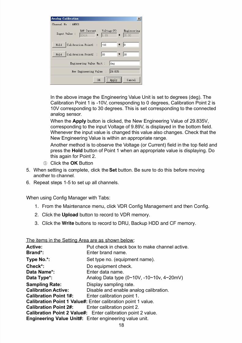
8102019 Ome44376d Vr3000 Mainte Cof26amp3bmol
httpslidepdfcomreaderfullome44376d-vr3000-mainte-cof26amp3bmol 2057
18
In the above image the Engineering Value Unit is set to degrees (deg) TheCalibration Point 1 is -10V corresponding to 0 degrees Calibration Point 2 is10V corresponding to 30 degrees This is set corresponding to the connectedanalog sensor
When the Apply button is clicked the New Engineering Value of 29835Vcorresponding to the input Voltage of 989V is displayed in the bottom fieldWhenever the input value is changed this value also changes Check that theNew Engineering Value is within an appropriate range
Another method is to observe the Voltage (or Current) field in the top field andpress the Hold button of Point 1 when an appropriate value is displaying Dothis again for Point 2
⑤ Click the OK Button
5 When setting is complete click the Set button Be sure to do this before movinganother to channel
6 Repeat steps 1-5 to set up all channels
When using Config Manager with Tabs
1 From the Maintenance menu click VDR Config Management and then Config
2 Click the Upload button to record to VDR memory
3 Click the Write buttons to record to DRU Backup HDD and CF memory
The items in the Setting Area are as shown below Active Put check in check box to make channel activeBrand Enter brand name
Type No Set type no (equipment name)
Check Do equipment checkData Name Enter data nameData Type Analog Data type (0~10V -10~10v 4~20mV)
Sampling Rate Display sampling rateCalibration Active Disable and enable analog calibrationCalibration Point 1 Enter calibration point 1
Calibration Point 1 Value Enter calibration point 1 valueCalibration Point 2 Enter calibration point 2Calibration Point 2 Value Enter calibration point 2 valueEngineering Value Unit Enter engineering value unit
8102019 Ome44376d Vr3000 Mainte Cof26amp3bmol
httpslidepdfcomreaderfullome44376d-vr3000-mainte-cof26amp3bmol 2157
19
Note For -marked boxes values that are set at the Analog Calibration dialog box aredisplayed
Equipment Category Set equipment categoryBoard Name Enter board names where channels are presentNote Enter note
Marked Items For easy identification of input source enter Equipment CategoryBrand Type No Data and Name
25 Digital Signal
Digital signal is connected via Junction Box IF-8530 (optional for VR-3000S) The
receivable signal is 10-32 V for voltage signal or contact signal For voltage signal
connect to A and B input terminals on the Junction Box For contact signal connect to B
and G input terminals on the Junction Box Also make a short-circuit between the 24 and
A input terminals with a jumper wire
To set up the Digital tab
1 Click the Digital tab
2 Select a channel from the Information Area
3 Set up the digital signal from the Setting Area Refer to the following individual item
explanation
In the factory settings there is no preset data when the Select Equipment button is
pressed In the case that the setup was completed on another ship and saved using
Reflect Equipment import the data by clicking Select Equipment and choosing the
saved data
4 When setting Digital Signal to each 64 channel group perform the following
directions1 Click the Calibration button in the setting area
8102019 Ome44376d Vr3000 Mainte Cof26amp3bmol
httpslidepdfcomreaderfullome44376d-vr3000-mainte-cof26amp3bmol 2257
20
2 Check the active column of the channel group being set
3 Enter the status in columns 0 and 1 of that group
4 Click the OK Button
5 When finished setting up click the Set button
6 Repeat steps 2-5 to set up other channels
When using Config Manager with Tabs
1 From the Maintenance menu click VDR Config Management
2 Click the Upload button to record to VDR memory
3 Click the Write buttons to record to DRU Backup HDD and CF memory
The items in the Setting Area are as shown below
Active Put check in check box to make channel activeBrand Enter brand name
Type No Set type no (equipment name)Check Do equipment checkData Name Enter and display data nameContact Type Set contact type NO normal open NC normal closeSampling Rate Display sampling rateCalibration Active Disable and enable digital calibrationActive Status (1) Set status display when (1) is activeActive Status (0) Set status display when (0) is activeEquipment Category Set equipment categoryBoard Name Enter board names where channels are presentNote Enter note
Marked Items For easy identification of input source enter Equipment CategoryBrand Type No Date and Name
8102019 Ome44376d Vr3000 Mainte Cof26amp3bmol
httpslidepdfcomreaderfullome44376d-vr3000-mainte-cof26amp3bmol 2357
21
26 Audio
Microphone and VHF audio settings are performed in the Audio tab
Set the items in the Audio tab as shown below
1 Click the Audio tab
2 Select channel from the Information Area3 Click Select Equipment in the Setting Area
4 Click on the connected device in the indicated channel The setting contents aredisplayed in the Information and Setting Areas
5 If required update the item contents in the Setting Area Refer to the detailed itemexplanation below
6 After completing settings for a channel click the Set buttonNote Be sure to click the Set button before moving to another channel
7 Repeat steps 2-6 to set up other channels
8102019 Ome44376d Vr3000 Mainte Cof26amp3bmol
httpslidepdfcomreaderfullome44376d-vr3000-mainte-cof26amp3bmol 2457
22
When using Config Manager with tabs
1 From the Maintenance menu click VDR Config Management
2 Click the Upload button to record to VDR memory
3 Click the Write buttons to record to DRU Backup HDD and CF memory
MIC testDo the MIC test to check whether audio is received clearly in adequate level or not
1 Click the MIC TEST button in the Setting Area
2 Click the TEST button in the MIC Test dialogue box MIC test results are displayed in
the MIC Test dialogue box
3 Click the Close button to close the dialogue box
Note Not the same recordingplayback function as the previous Web Configuratorsoftware
Continuous MIC TestRun the continuous MIC test as needed accordingly
1 Click the Continuous MIC Test button in the Setting Area2 Set up how many times to perform in the Continuous MIC Test dialogue box and click
the Test button
3 Click the Close button to close the dialogue box
8102019 Ome44376d Vr3000 Mainte Cof26amp3bmol
httpslidepdfcomreaderfullome44376d-vr3000-mainte-cof26amp3bmol 2557
23
Active Put check in check box to make channel activeBrand Enter and display brand nameType No Set type no (equipment name)Check Do equipment checkData Name Enter data nameInput Type Enter input type Sampling Data Bit Displays sampling data bit rate
Sampling Frequency Displays Sampling FrequencyCodec Sets MIC typeMIC Test Active M1M3M5 Put a checkmark when performing MIC Test of M1M3M5MIS Test Active M2M4M6 Put a checkmark when performing MIC Test of M2M4M6 MIC M1M3M5 Position Enter MIC position of MIC M1M3M5MIC M2M4M6 Position Enter MIC position of MIC M2M4M6Threshold Level M1M3M5 Enter MIC test threshold level of MIC M1M3M5Threshold Level M2M4M6 Enter MIC test threshold level of MIC M2M4M6Equipment Category Set equipment categoryBoard Name Enter board names where channels are present
Note Enter note Marked Items For easy identification of input source enter Equipment Category BrandType No Date and Name
8102019 Ome44376d Vr3000 Mainte Cof26amp3bmol
httpslidepdfcomreaderfullome44376d-vr3000-mainte-cof26amp3bmol 2657
24
27 Alarm
Alarm and Alarm Status settings are found in the Alarm tab
The Alarm tab shows the following information about alarms Click the Time Categoryand Name tabs in the title bar to sort
Time Time of alarm
Category Alarm categoryName Name of alarm
Number Alarm number
Status Alarm status
Alarm Search
1 Click the Search button above the Alarm tab The Search dialogue box appears
2 Add a checkmark to any desired search items (multiple items can be selected)
Start Time Display name of alarms generated after a certain time
End Time Display name of alarms generated before a certain time
Name Display information for alarm name entered
8102019 Ome44376d Vr3000 Mainte Cof26amp3bmol
httpslidepdfcomreaderfullome44376d-vr3000-mainte-cof26amp3bmol 2757
25
Number Display information for alarm number entered
Status Display alarm status for alarm name entered
3 In the checked items column input the desired search items
4 Click the Search Button
Close the Search box to cancel a search
Note During a search the upper left Mode changes from Play to Search andDisplay search related information
8102019 Ome44376d Vr3000 Mainte Cof26amp3bmol
httpslidepdfcomreaderfullome44376d-vr3000-mainte-cof26amp3bmol 2857
26
28 Event
Click the items shown below to sort by item selected
Note You can sort the items in ascending order () descending order () and
initialization order (no symbol)
Time Time an event occurred
Category Category of an event
Name Name of an event
Contents1 Display data associated with log
Contents2 Display data associated with log
Event Search
Do the following to search events
1 Click the Search button on the upper right of the Event tab
2 In the dialogue box add a checkmark to desired search items Multiple items can bechecked
Start Time Display name of event generated after a certain time
End Time Display name of event generated before a certain time
Name Display event names entered
Number Display event numbers entered
Status Display event status entered
Enter information about the checked event to search in the character input box
3 Click the Search button
Note The mode changes from Play to Search when performing a search
8102019 Ome44376d Vr3000 Mainte Cof26amp3bmol
httpslidepdfcomreaderfullome44376d-vr3000-mainte-cof26amp3bmol 2957
27
29 Hardware
The Hardware tab provides information about the system hardware
The buttons in the Setting window work as follows
Self Check Status Display status of self check
CPU Display information about the CPU
Memory Size Display memory size
CPU Board Display status of CPU board
Audio Board Display status of Audio board
Serial Board Display status of Serial board
Radar Interface Board Display status of Radar Interface boardNote Enter and display note
Marked items are optional
8102019 Ome44376d Vr3000 Mainte Cof26amp3bmol
httpslidepdfcomreaderfullome44376d-vr3000-mainte-cof26amp3bmol 3057
28
210 JB
Connect the Junction Box to the DCU before turning on the system
The JB tab functions to set up the Junction Box
The basic procedure for setting up the Junction Box is as follows
1 Click the JB tab2 Select a Junction Box from the Information Area
3 Set up the Junction Box from the Setting Area
4 Click the Set button (Be sure to do this before moving to another channel)5 Click the Check button to perform an inspection on all channels In the Information
Area check column either OK or NG (No Good) is displayed
When using Config Manager with Tabs
1 From the Maintenance menu click VDR Config Management
2 Click the Upload button to record to VDR memory
3 Click the Write buttons to record to DRU Backup HDD and CF
The items in the Setting window work as followsActive Put check in check box to make channel activeNo Display Junction Box numberIP Address Display IP address of Junction Box acquired by VDRMAC Address Display MAC address of Junction Box acquired by VDRCheck Enable and disable equipment checkNote Enter note
Marked items are optional
8102019 Ome44376d Vr3000 Mainte Cof26amp3bmol
httpslidepdfcomreaderfullome44376d-vr3000-mainte-cof26amp3bmol 3157
29
211 Life Time
The Life Time tab controls consumable parts
The basic procedure for using the Life Time tab is as follows
1 Click the Life Time tab
2 Select a Type No in the Information Area3 Set up the chosen part from Setting Area
4 Click the Set button
Note Be sure to click the Set button before moving to set up a different Type
The items in the Setting window work as follows
Type No Enter and display type no
Data Name Enter and display data name
Level Set replacement level Legal Exchange Parts or Normal Exchange Parts
Replace Date Enter and display recommended day of replacement
Lifetime Term Not usedNote Enter and display note
The Status column of the Information Area displays as follows
OK The recommended date of replacement shown in the Replace Date
box in the Information window has not passed
Out of Date The date of replacement has passed
None The date of replacement has not been set
8102019 Ome44376d Vr3000 Mainte Cof26amp3bmol
httpslidepdfcomreaderfullome44376d-vr3000-mainte-cof26amp3bmol 3257
30
212 Network
The Network tab sets the system network
The basic procedure for setting up the system network is as follows
1 Click the Network tab
2 Select a port from the Information Area
3 Set up the network from the Setting Area
4 Click the Set button
Note1 Be sure to click the Set button before moving to set up a different Port
Note2 After setting the system network reboot the VDR to apply the settings
The items in the Setting window work as follows
LAN Type Enter LAN type Public LAN or JB LAN
MAC Address Enter MAC address
IP Address Enter IP address
Subnet Mask Enter subnet mask
Gateway Address Enter gateway address
Live Play Multicast Mode (Only JB LAN) Check box to enable live player multicast
mode
Multicast Address (Only Public LAN) Enter and display live player multicast addressNote Enter note
Marked items are optional
8102019 Ome44376d Vr3000 Mainte Cof26amp3bmol
httpslidepdfcomreaderfullome44376d-vr3000-mainte-cof26amp3bmol 3357
31
213 System
The System tab sets system related functions
The basic procedure for using the System tab is as follows
1 Click the System tab
2 Set up the chosen item from the Setting Area
3 Click the Set button
Note Be sure to click the Set button before moving to a different tab
The items in the Setting window work as follows
VDR Type Enter type of VDR
VDR Model Enter model number of VDR
Radar Interface Check Enable and disable checking of the Radar Interface board
Junction Box Count Enter number of junction boxes in system
DRU Flash Count Enter number of DRU flash disks in system Set 1 when DRU
serial no is 5000 and more Set 3 when DRU serial no is less
than 5000
DRU Capacity Display capacity of DRU
Backup HDD Capacity Display capacity of Backup HDD
VDR Config Version Display version no of VDR
VDR Config Date Display the number of hours the VDR settings have
been saved
VDR Config Code Display configuration identity code
Installation Engineer Enter name of the equipment installer
Installation Company Enter name of installers company
8102019 Ome44376d Vr3000 Mainte Cof26amp3bmol
httpslidepdfcomreaderfullome44376d-vr3000-mainte-cof26amp3bmol 3457
32
Installation Date Enter the date of the installation
MIC Test Time Enter the date of the MIC test
Note Enter note Marked items are optional
USB memory logging Do not check Enable
IEEE1394 BUS Error Auto Restart function Not used
IEEE1394 Active Node Count Do not change the default value of 3 (However set to 5
for serial number 5000 or less of DRU)
IEEE1394 Recover Process Limit Count Do not change the default value of 10
DRU Error Auto Restart function Not used
REBOOT DELAY TIME (sec) Do not change the default value of 10
LIMIT REBOOT COUNT Do not change the default value of 10
Live Player Max Connection Count The max number of Live Player V4 that can be
connected simultaneously The default no is two
but a maximum of five can be set here After you
change this option reboot the VDR to apply the
setting Disconnect the cable connected with
Live Player V4 (PC) from the VDR and thenreconnect it
214 Software
The Software tab sets and display software-related operations
The basic procedure for using the Software tab is as follows
1 Click the Software tab
2 Set up the chosen Item from the Setting Area
3 Click the Set button
8102019 Ome44376d Vr3000 Mainte Cof26amp3bmol
httpslidepdfcomreaderfullome44376d-vr3000-mainte-cof26amp3bmol 3557
33
The items in the Setting window work as follows
VDR System Program Display the VDR system program no
Process Version Display the process version
Power Distribution Unit (PDU) Display the version no of the PDU
Operation System Display the version no of the OS
Audio Driver Display the version no of the audio driverRAP Version Enter the version no of the RAP
AP Version Enter the version no of the AP
JB1-8 Boot Program Display the no of the RJB Boot program for Junction Boxes
1 to 8
JB1-8 App Program Display the no of the RJB App program for Junction Boxes
1 to 8
Watch Dog Interval Do not change the default value of 60 (Enter the process
response time A process is repeated if there is no response
within the time interval set here)
Giveup Interval Do not change the default value of 300 (Enter the restart
watch time The restarting of a process is stopped when the
number of times it has been restarted is exceeded within the
interval set here)
Refork Limit Do not change the default value of 10 (Enter the upper limit
for process restart The restarting of a process is stopped
when the number of times it has been restarted exceeds the
Give up Interval)
Note Enter note
Marked Items are optional
8102019 Ome44376d Vr3000 Mainte Cof26amp3bmol
httpslidepdfcomreaderfullome44376d-vr3000-mainte-cof26amp3bmol 3657
34
215 GPS
The GPS tab sets GPS-related parameters
The basic procedure for using the GPS tab is as follows
1 Click the GPS tab
2 Set up the chosen channel from the Information window3 Set up the chosen item in the Setting Area
4 Click the Set button
5 Repeat steps 2-4 to set up each Channel
6 Click the Check button to perform an inspection on all channels In the Information Area check column either OK or NG (No Good) is displayed
The items in the Setting window work as follows
Priority Display priority order
Date and Time SourceShip Position Source Set GPS source channel (serial channel
number for ZDA sentence)
Check Enable and disable checking
GPS Antenna Position From Bow Enter position of GPS antenna from bow
GPS Antenna Position From Stern Enter position of GPS antenna from stern
GPS Antenna Position From Port Enter position of GPS antenna from port
GPS Antenna Position From Starboard Enter position of GPS antenna from starboard
GPS Failure Threshold If the ZDA is input within the set time limit
the system restarts synchronized If not
input within the time limit the system restarts
without synchronization
8102019 Ome44376d Vr3000 Mainte Cof26amp3bmol
httpslidepdfcomreaderfullome44376d-vr3000-mainte-cof26amp3bmol 3757
35
GPS Delay Time by Time Sync Enter minimum time delay for time
synchronization Time synchronization is started
only in the time set here
GPS Difference Interval The time set here is added to the GPS time to
synchronize the system time Leave at the default
0 value setting
GPS Sync Giveup Time If the system receives the GPS time within the
time set the system synchronizes with the time
When not receiving a signal the system displays
an ldquoerror 26rdquo message
ZDA Timeout Enter value (seconds) for ZDA timeout (234 error)
from GPS
Note Enter and display note
Marked Items are optional
216 VesselThe Vessel tab sets and displays own ships information such as name and IMO number
The basic procedure for using the Vessel tab is as follows
1 Click the Vessel tab
2 Set up information in the Setting window
3 Click the Set button (Be sure to do this before moving to another port)
4 From the Maintenance menu click VDR Config Management and then Config5 Click the Write buttons to save data to the DRU backup HDD CF
The buttons in the Setting window works as follows
Vessel Name Enter name of vessel
Vessel IMO Number Enter IMO number of vessel
Vessel Flag Enter flag of vessel
Approval of Authority Enter name of approving authority
Note Enter note
Marked items are optional
8102019 Ome44376d Vr3000 Mainte Cof26amp3bmol
httpslidepdfcomreaderfullome44376d-vr3000-mainte-cof26amp3bmol 3857
36
217 Delivery
The Delivery tab functions to transmit data from the VDR to a PC via Ethernet LAN Do
not use this function during live connection
The basic procedure for using the Delivery tab is as follows
1 Click the Delivery tab
2 Click the Add button to show the Delivery Config window
3 Select protocol from the Protocol drop-down box (Unicast or Multicast)
4 Enter IP address in the IP address input box
5 Enter port number in the port number input box
6 Click the tab of the data to send (Analog Digital or Serial)
7 Select the channel of the data to send
8 If Serial was selected at step 6 select applicable data sentence from the Inactivewindow Click the right arrow to move the data sentence to the Active window
9 Click the OK button to close the Delivery Config window
10 The settings are listed in a table in the Delivery window Check the checkbox in the
Active column and then click the Set button
The buttons in the Setting window works as follows
Set Save edited settings
Add Create new delivery settings
Modify Modify selected delivery settings
Delete Delete selected delivery settings
8102019 Ome44376d Vr3000 Mainte Cof26amp3bmol
httpslidepdfcomreaderfullome44376d-vr3000-mainte-cof26amp3bmol 3957
37
3 How to Back up Configuration DataThis chapter shows how to back up configuration data to various storage media
Configuration data can be opened with Word Pad or any text editor other than Notepad
31 How to Back up Configuration Data to the Startup CompactFlash (CF)
Back up data to the startup CF after setting the VDR Configuration data is created on the
CF as a configini file
Note When the error shown below occurs during the downloading or uploading of
configuration data check the connection of the DRU Backup HDD and CF and then
upload or download the configuration data again
[CONN] Download failed
[CONN] Could not upload config file
If error occurs again re-install the VDR Maintenance Viewer
Do the following to back up data to a CF
1 Set up parameters on the tabs referring to Chapter 2
2 Click the Maintenance menu
3 Select VDR Config Management
4 Click the Upload button
5 A confirmation box appears click the OK button to start uploading to the VDR
6 Click the Write button where the arrow connects between VDR and DRU BackupHDD
7 A confirmation window appears click the OK button to save the configuration data tothe DRU and Backup HDD
8102019 Ome44376d Vr3000 Mainte Cof26amp3bmol
httpslidepdfcomreaderfullome44376d-vr3000-mainte-cof26amp3bmol 4057
38
8 Click the Write button where the arrow connects between the VDR and CF
9 A confirmation window appears click the OK button to save the configuration data tothe startup CF
10 Check that the PC VDR DRU Backup HDD and CF share the same VDR configcode
32 How to Back up Configuration Data to a PC
Configuration data saved to the PC can be edited with Wordpad and shared with other
vessels For future service ease it is recommended to backup configuration data to the
PC and have the data on board the vessel Also it is recommended to upload this data to
Furuno SMS (Service Management System) If unable to upload to Furuno SMS please
contact the Service Center Furuno Japan
To back up configuration data to the PC do as follows
1 Set up parameters on the tabs referring to Chapter 2
2 Click the Maintenance menu
3 Select VDR Config Management
4 Click the Export to button
5 A confirmation window appears click the OK button
6 Select where to save the data enter file name then click the Open button
7 Confirm that back up file is in the location selected
33 How to restore the default settings
Click the Default button on the VDR Config Management window to restore the default
settings of the DRU Backup HDD CF and VDR Maintenance Viewer
8102019 Ome44376d Vr3000 Mainte Cof26amp3bmol
httpslidepdfcomreaderfullome44376d-vr3000-mainte-cof26amp3bmol 4157
39
4 How to Upload Configuration Datafrom a PCThe procedure below shows how to upload configuration from the PC to aVR-3000VR-3000S
1 Click the Maintenance menu
2 Select VDR Config Management
3 Click the Import from button
4 The Open window appears Select configuration data and then click the Open button
5 Click the Upload button to upload data to the VR-3000VR-3000S
6 Click the Write buttons to save data to the DRU backup HDD and CF
8102019 Ome44376d Vr3000 Mainte Cof26amp3bmol
httpslidepdfcomreaderfullome44376d-vr3000-mainte-cof26amp3bmol 4257
40
5 Media ManagementThe media management feature deletes data from recording media initialization the
system etc There are two method LAN connection and Direct connection The Direct
connection takes longer time than the LAN connection Basically use the LAN connection
method
Note Initialization or creation of recording media is not available when Source Select onthe Live Player V4 is selected to Backup HDD
51 Initialization
This section shows how to delete data from the recording media Configuration data is
not deleted After performing the software configuration delete the data from the DRU
and HDD
Do the following to delete data from the DRU (LAN connection)
1 Set the PlaybackCPU switch in the DCU to the CPU position
2 Use an Ethernet cross cable to connect the PC to J14 (DATA) in the DCU (See page5)
3 Open the Tool menu
4 Select Media Management to open the VDR Media Management window
5 Check that IP address shown in the ldquoLAN Connect to IPrdquo in VDR Media Table Area isthe same as the IP address access point
6 Select ldquoLAN Connect to IPrdquo in the VDR Media Table column
8102019 Ome44376d Vr3000 Mainte Cof26amp3bmol
httpslidepdfcomreaderfullome44376d-vr3000-mainte-cof26amp3bmol 4357
41
7 Click the Analyze button A list of recording media connected to the VDR appears
Put a checkmark in the checkbox of the Select column for the DRU in the Name columnNote If there are several flash memories in the DRU all flash memories are shownCheck all flash memories shown
8 Select ldquoDRU Initializerdquo from the Operation dropdown list in the Operation area
10 Click the Run button
Do the following to delete data from the DRU (Direct connection)
1 Start Live Player V4 software
2 Open the Tool menu and select Source Select Select Live from the pull-downmenu
3 Click the Alarm tab and open Alarm History
4 Set the PlaybackCPU switch in the DCU to the Playback position
5 Wait approx 10 minutes and confirm that Alarm 174 occurs on Alarm History of LivePlayer V4
6 Connect an IEEEE1394 cable between J6 in the DCU and the PC
7 Open the Tool menu
8 Select Media Management to show the VDR Media Management window
9 Select Direct in the VDR Media Table column
10 Click the Analyze button A list of recording media connected to the VDR appears
11 Put a checkmark in the checkbox of the Select column for the DRU in the Namecolumn
Note If there are several flash memories in the DRU all flash memories are shownCheck all flash memories shown
12 Select ldquoDRU Initializerdquo from the Operation dropdown list in the Operation area
13 Enter password in the password column
14 Click the RUN button
8102019 Ome44376d Vr3000 Mainte Cof26amp3bmol
httpslidepdfcomreaderfullome44376d-vr3000-mainte-cof26amp3bmol 4457
42
Delete data from the Backup HDD as follows (LAN connection)
1 Set the PlaybackCPU switch in the DCU to the CPU position
2 Check that an Ethernet cross cable is connected between J14 in the DCU and the PC
3 Open the Tool menu
4 Select Media Management to open the VDR Media Management window
5 Check that IP address shown in the LAN Connect to IP in VDR Media Table Area is
the same as the IP address access point6 Select LAN Connect to IP in the VDR Media Table column
7 Click the Analyze button
8 A list of recording media connected to the VDR appears
9 Put a checkmark in the box of the Select column for the Backup HDD in the Namecolumn Select ldquoBackup HDD Initializerdquo from the Operation dropdown list in theOperation area
10 Click the Run button
Delete data from the Backup HDD as follows (Direct connection)
1 Start Live Player V4 software
2 Open the Tool menu and select Source Select Select Live from the pull-downmenu
3 Click the Alarm tab and open Alarm History
4 Set the PlaybackCPU switch in the DCU to the Playback position
5 Wait approx 10 minutes and confirm that Alarm 174 occurs on Alarm History of LivePlayer V4
6 Connect an IEEE1394 cable between J6 in the DCU and the PC
7 Open the Tool menu
8 Select Media Management to open the VDR Media Management window9 Select Direct in the VDR Media Table window
10 Click the Analyze button A list of recording media connected to the VDR appears
11 Put a checkmark in the check box of the Select column for the Backup HDD in theName column Select ldquoBackup HDD Initializerdquo from the Operation dropdown list in theOperation area
12 Enter password
13 Click the Run button
8102019 Ome44376d Vr3000 Mainte Cof26amp3bmol
httpslidepdfcomreaderfullome44376d-vr3000-mainte-cof26amp3bmol 4557
43
52 CreationThe Creation feature initializes recording media
Note1 This feature deletes ALL configuration data Backup all VDR configuration data
Note2 When you initialize medium that is a different format for the DRU or Backup HDDdelete all partitions with the disk management tool of Windows
Note3 When the Creation is failed try again If you can not initialize recording media tryunder condition as shown below
Do the Creation by the direct connection (When the Creation by the LAN
connection is failed)
Delete all partitions of the DRU or Backup HDD with the disk management tool of
Windows to do the Creation
If the Creation is still failed request service to repairreplace the DRU or Backup
HDD
Initialize the DRU as follows (LAN connection)
1 Set the PlaybackCPU switch in the DCU to the CPU position
2 Check that an Ethernet cross cable is connected between J14 in the DCU and the PC
3 Open the Tool menu
4 Select Media Management to open the VDR Media Management window
5 Check that IP address shown in the LAN Connect to IP in VDR Media Table Area isthe same as the IP address access point
6 Check ldquoLAN Connect to IPrdquo in the VDR Media Table column
7 Click the Analyze button A list of recording media connected to the VDR appears
8 Put a checkmark in the box of the Select column for the DRU in the Name column
Select ldquoDRU Creationrdquo from the Operation dropdown list in the Operation area
9 Click the Run button
Initialize the Backup HDD as follows (LAN connection)
1 To format the Backup HDD place a checkmark in the Select column of the listedrecord media in the Name column of the VDR Media Management dialogue box
2 From the Operation drop down list of the Operation area select ldquoBackup HDDCreation (Radar) or ldquoBackup HDD Creationrdquo
Two partition tools are available for the Backup HDD in the Media Management as
below
Backup HDD creation
This tool is used when the number of the SXGA video signal connected to the BackupHDD is the same as the DRU The same partition is created on both DRU and HDD
(1) When two SXGA video signals are recorded onto the HDD while 9-GB DRU isconnected
(2) When an SXGA video signal is recorded onto the HDD while 6-GB DRU isconnected
Backup HDD creation (radar)
This tool is used when two SXGA video signals are recorded onto the HDD with 6-GB
DRU connected The HDD has an area (radar) to record the second radar signal inaddition to the same partition as the DRU This tool cannot be used when 9-GB DRUis connected
3 Press the Run Button
8102019 Ome44376d Vr3000 Mainte Cof26amp3bmol
httpslidepdfcomreaderfullome44376d-vr3000-mainte-cof26amp3bmol 4657
44
Initialize the DRU as follows (Direct connection)
1 Start Live Player V4 software
2 Open the Tool menu and select Source Select Select Live from the pull-downmenu
3 Click the Alarm tab and open Alarm History
4 Set the PlaybackCPU switch in the DCU to the Playback position
5 Wait approx 10 minutes and confirm that Alarm 174 occurs on Alarm History of LivePlayer V4
6 Connect an IEEE1394 cable between J6 in the DCU and the PC
7 Open the Tool menu
8 Select Media Management to open the VDR Media Management window
9 Select Direct in the VDR Media Table window
10 Click the Analyze button A list of recording media connected to the VDR appears
11 Put a checkmark in the box of the Select column for the DRU and the desiredrecording media in the Name column In the Operation dropdown list of the Operationarea select ldquoDRU Creationrdquo
12 Enter password in the password column
13 Click the Run button
Initialize the Backup HDD as follows (Direct Connection)
1 To format the Backup HDD place a checkmark in the Select column of the listedrecord media in the Name column of the VDR Media Management dialogue box
2 From the Operation column of the Operation area select ldquoBackup HDD Creation(Radar) or ldquoBackup HDD Creationrdquo
Backup HDD creation
This tool is used when the number of the SXGA video signal connected to the BackupHDD is the same as the DRU The same partition is created on both DRU and HDD
(1) When two SXGA video signals are recorded onto the HDD while 9-GB DRU is
connected
(2) When an SXGA video signal is recorded onto the HDD while 6-GB DRU is
connected
Backup HDD creation (radar)
This tool is used when two SXGA video signals are recorded onto the HDD with 6-GBDRU connected The HDD has an area (radar) to record the second radar signal inaddition to the same partition as the DRU This tool cannot be used when 9-GB DRUis connected
3 Enter the password in the Password column
4 Press the Run Button
8102019 Ome44376d Vr3000 Mainte Cof26amp3bmol
httpslidepdfcomreaderfullome44376d-vr3000-mainte-cof26amp3bmol 4757
45
53 How to Enable Recording Area on the Backup HDD
This function enables writing over a recording area To prevent falsification of data all
recording areas must be saved otherwise this function is disabled To use this function push
the SAVE button Save the data before doing this procedure
Note Software version 135 or higher can enable writing over a recording area even if
all recording areas are not saved
Recording enable (LAN connection)
1 Set the PlaybackCPU switch in the DCU to the CPU position
2 Check that an Ethernet cross cable is connected between J14 in the DCU and the PC
3 Open the Tool menu
4 Select Media Management to open the VDR Media Management window
5 Check that IP address shown in the ldquoLAN Connect to IPrdquo in VDR Media Table Area isthe same as the IP address access point
6 Select ldquoLAN Connect to IPrdquo in the VDR Media Table column7 Click the Analyze button A list of recording media connected to the VDR appears
8 Put a checkmark in the box of the Select column for the Backup HDD in the Namecolumn
9 Select ldquoBackup HDD Recording Area Enablerdquo from the Operation dropdown list in theOperation area
10 Click the Run button
Recording enable (Direct connection)
1 Start Live Player V4 software
2 Open the Tool menu and select Source Select Select Live from the pull-down menu3 Click the Alarm tab and open Alarm History
4 Set the PlaybackCPU switch in the DCU to the Playback position
5 Wait approx 10 minutes and confirm that Alarm 174 occurs on Alarm History of LivePlayer V4
6 Connect an IEEE1394 cable between J6 in the DCU and the PC
7 Open the Tool menu
8 Select Media Management to open the VDR Media Management window
9 Select Direct in the VDR Media Table window
10 Click the Analyze button A list of recording media connected to the VDR appears11 Put a checkmark in the box of the Select column for the Backup HDD in the Name
column
12 Select ldquoBackup HDD Recording Area Enablerdquo from the Operation dropdown list in theOperation area
13 Enter password
14 Click the Run button
8102019 Ome44376d Vr3000 Mainte Cof26amp3bmol
httpslidepdfcomreaderfullome44376d-vr3000-mainte-cof26amp3bmol 4857
46
6 Other Functions
61 Software Management
The software download feature downloads VDR system software to the PC
To download software
1 Click the Maintenance menu
2 From the Software Management menu click Software Download to show theSoftware Download window
3 Enter the IP address 1000100 in the IP address box in the Update Server area
4 Click the Download Software button
5 The confirmation window appears click the OK button
The Software Backup Execute window shows the results of the download
Software is downloaded to C Program Files VDR Viewer Viewer Backup The software file
name is vdrtar
To Update Software
VDR system program version 16x can update the software with the procedure shownbelow
Note Do not update the file downloaded in procedures above
1 Click the Maintenance menu
2 From the Software Management menu click Software Upload to show the SoftwareUpload area
3 Click the Select button to show the Open window
4 Select update file (vdrtar) and click the Open button
8102019 Ome44376d Vr3000 Mainte Cof26amp3bmol
httpslidepdfcomreaderfullome44376d-vr3000-mainte-cof26amp3bmol 4957
47
5 Check the displayed Software information is correct
6 Enter the IP address 1000100 in the IP address box in the Update Server area
7 Enter password
8 Click the Update button
After the updating is completed the VDR is automatically restarted
Note Click the Restore button on the Software Update window to restore previoussoftware version This feature is available after updating the software
62 Password Management
The password can be changed for a serviceman to access the equipment Contact
FURUNO to get the default password to use during installation
Serviceman password
1 Click the Maintenance menu2 Select Change Serviceman Password from Password Management to show the
Change Serviceman Password window
3 Enter current password in the Old Password box
4 Enter the new password in the New Password box of the Change Password area
5 Enter new password again in the Confirm New Password box
6 Click the OK button
Audio password
The audio password set at the VDR Maintenance Viewer can be removed to enable
audio access without password1 Click the Maintenance menu
2 Select Change Audio Password from Password Management to show the Change Audio Password window
3 The confirmation window appears click the OK button
8102019 Ome44376d Vr3000 Mainte Cof26amp3bmol
httpslidepdfcomreaderfullome44376d-vr3000-mainte-cof26amp3bmol 5057
48
63 Record ComparisonThe integrity of the DRU and Backup HDD recordings can be compared This function isused by the RampD engineer for debugging
Follow the procedure as shown below
1 Click the Maintenance menu2 Select Record Comparison to show the Record Comparison window
The results are shown every 15 seconds in the Record Comparison window
8102019 Ome44376d Vr3000 Mainte Cof26amp3bmol
httpslidepdfcomreaderfullome44376d-vr3000-mainte-cof26amp3bmol 5157
49
64 Software History
This section shows you to save and configure software history (communications record)
How to save software history
Note When the error dialog appears while saving the software history restart the VDR
Maintenance Viewer
1 Click the Maintenance menu
2 Select Software History Collect
3 Click the Select button The Open dialog box appears
4 Select where to save the data then click the Open button
5 Select desired save condition then click the OK buttonNone No savingAt Once Save the software history manually Saving begins as soon as the OK button is clickedPeriodic For debugging Do not use otherwise The intervals are 30 sec 60 secand 120 secAlarm Detection For debugging Do not use otherwise Software history is savedwhen specified alarm is released Enter alarm number
How to configure software communications record
The RampD engineer uses this function for debugging Do not do this procedure unless
required Malfunction can result
1 Click the Maintenance menu
2 Select Software History Config
3 Do the followingProcess Select the type of communications record to save ALL saves allcommunications records
Detail Hide or show detailed information4 Click the Send button
8102019 Ome44376d Vr3000 Mainte Cof26amp3bmol
httpslidepdfcomreaderfullome44376d-vr3000-mainte-cof26amp3bmol 5257
50
65 Easy SetupThis feature sets equipment settings in batch and creates a data file of those settings
Default template The default template is created with the settings entered at installation
1 Click the Maintenance menu
2 Select Easy Setup to show the Template Selection window
3 Select Default Template
4 Click the Start button to show the Easy Setup window
5 Right click the channels (Radar Audio Digital Serial Analog) then select Edit toshow the Equipment Selection window
6 From the Equipment Directory window select equipment connected to the selectedchannel and then click the OK button
7 Repeat steps 5 and 6 to select equipment settings for each channel
8 Click the Save button in the Easy Setup window to show the Save window
9 Select where to save the file and enter file name
10 Click the Save button
8102019 Ome44376d Vr3000 Mainte Cof26amp3bmol
httpslidepdfcomreaderfullome44376d-vr3000-mainte-cof26amp3bmol 5357
51
Specific template Use a file already created
1 Click the Maintenance menu
2 Select Easy Setup to show the Template Selection window
3 Check Specified Template
4 Click the Select button and then select the file to edit
5 Click the Start button to show the Easy Setup window
6 Right click the channels (Radar Audio Digital Serial Analog) then select Edit toshow the Equipment Selection window
7 From the Equipment Directory window select equipment connected to the selectedchannel and then click the OK button
8 Repeat steps 6 and 7 to select equipment settings for each channel
9 Click the Save button in the Easy Setup window to show the Save window
10Select where to save the file and enter file name
11 Click the Save button
66 Equipment Management
This feature controls the import and export of equipment settings
Import data file
Import data files of equipment settings created in Easy Setup etc to the VDR
1 Click the Maintenance menu
2 Select Import from Equipment Management to show the Open window
3 Select the data file to import and click Open
Export data file
Export data files of equipment settings from the VDR to a PC
1 Click the Maintenance menu
2 Select Export from Equipment Management to show the Save window
3 Enter file name
4 Click the Save button
8102019 Ome44376d Vr3000 Mainte Cof26amp3bmol
httpslidepdfcomreaderfullome44376d-vr3000-mainte-cof26amp3bmol 5457
52
67 PC_RAP
This feature enables the same operation of the RAP (Remote Alarm Panel) from a PC
Select PC_RAP from the Tool menu to show the PC_RAP window
The buttons in the PC_RAP window function as shown below
SAVE Stop recording in the area where recording is currently being done
ACK Silence audio alarm
The PC_RAP display shows the following information with LEDs
RAP_LEDs Display the status of LEDs on the RAPSave The Save button blinks yellow when pushed When the 4 memory
areas have data recorded to them the Save button lights orange when
pushed
Normal Lights (green) where there are no unconfirmed or not restored
alarms
Error Flashes (red) for not confirmed alarm Lights (red) for unrestored
alarm
8102019 Ome44376d Vr3000 Mainte Cof26amp3bmol
httpslidepdfcomreaderfullome44376d-vr3000-mainte-cof26amp3bmol 5557
53
Backup HDD Information Display status of backup HDD
Selected Display current recording area and its status in green for
normal operation and in red for abnormal operation
Size Display capacity of backup HDD
Alarm area displays unconfirmed alarms
Time Display time alarm was generatedNumber Display number of alarm
Name Display name of alarm
Pending Alarm displays the unrestored alarms out of confirmed alarms only
Time Display time alarm was generated
Number Display number of alarm
Name Display name of alarm
8102019 Ome44376d Vr3000 Mainte Cof26amp3bmol
httpslidepdfcomreaderfullome44376d-vr3000-mainte-cof26amp3bmol 5657
54
68 Other
Status Monitor
The status monitor feature provides comprehensive data about the status of the VDR
From the menu bar click Toolgt Status Monitor to show the Status Monitor window
The buttons in the Status Monitor window work as shown below
Reload Settings for automatic refreshing of the status monitor
ON Turn automatic refresh OFF
OFF The Status Monitor is refreshed every five seconds
Save Available when Reload ON is selected The contents of the Status Monitor can be
saved to a text fileUpdate Update the Status Monitor display
Close Close the Status Monitor display
8102019 Ome44376d Vr3000 Mainte Cof26amp3bmol
httpslidepdfcomreaderfullome44376d-vr3000-mainte-cof26amp3bmol 5757
VDR Error List
This feature compiles all the errors shown on the RAP for easy reference
Access from MenugtToolgtVDR Error List
The VDR error list contains the following information
NO Display the number of the error
Title Display the name of the error
Detail Display details about the error
Exchange Check
This feature removes the alarms generated when replacing the DRU or backup HDD
Access MenugtToolgtExchange Check select either DRU or Backup HDD and click OK
Reboot
Reboot the VDR
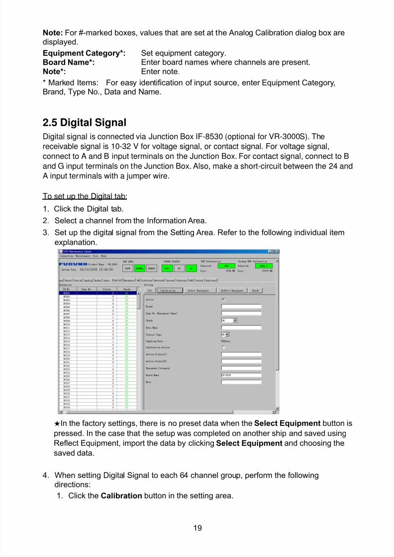
8102019 Ome44376d Vr3000 Mainte Cof26amp3bmol
httpslidepdfcomreaderfullome44376d-vr3000-mainte-cof26amp3bmol 2157
19
Note For -marked boxes values that are set at the Analog Calibration dialog box aredisplayed
Equipment Category Set equipment categoryBoard Name Enter board names where channels are presentNote Enter note
Marked Items For easy identification of input source enter Equipment CategoryBrand Type No Data and Name
25 Digital Signal
Digital signal is connected via Junction Box IF-8530 (optional for VR-3000S) The
receivable signal is 10-32 V for voltage signal or contact signal For voltage signal
connect to A and B input terminals on the Junction Box For contact signal connect to B
and G input terminals on the Junction Box Also make a short-circuit between the 24 and
A input terminals with a jumper wire
To set up the Digital tab
1 Click the Digital tab
2 Select a channel from the Information Area
3 Set up the digital signal from the Setting Area Refer to the following individual item
explanation
In the factory settings there is no preset data when the Select Equipment button is
pressed In the case that the setup was completed on another ship and saved using
Reflect Equipment import the data by clicking Select Equipment and choosing the
saved data
4 When setting Digital Signal to each 64 channel group perform the following
directions1 Click the Calibration button in the setting area
8102019 Ome44376d Vr3000 Mainte Cof26amp3bmol
httpslidepdfcomreaderfullome44376d-vr3000-mainte-cof26amp3bmol 2257
20
2 Check the active column of the channel group being set
3 Enter the status in columns 0 and 1 of that group
4 Click the OK Button
5 When finished setting up click the Set button
6 Repeat steps 2-5 to set up other channels
When using Config Manager with Tabs
1 From the Maintenance menu click VDR Config Management
2 Click the Upload button to record to VDR memory
3 Click the Write buttons to record to DRU Backup HDD and CF memory
The items in the Setting Area are as shown below
Active Put check in check box to make channel activeBrand Enter brand name
Type No Set type no (equipment name)Check Do equipment checkData Name Enter and display data nameContact Type Set contact type NO normal open NC normal closeSampling Rate Display sampling rateCalibration Active Disable and enable digital calibrationActive Status (1) Set status display when (1) is activeActive Status (0) Set status display when (0) is activeEquipment Category Set equipment categoryBoard Name Enter board names where channels are presentNote Enter note
Marked Items For easy identification of input source enter Equipment CategoryBrand Type No Date and Name
8102019 Ome44376d Vr3000 Mainte Cof26amp3bmol
httpslidepdfcomreaderfullome44376d-vr3000-mainte-cof26amp3bmol 2357
21
26 Audio
Microphone and VHF audio settings are performed in the Audio tab
Set the items in the Audio tab as shown below
1 Click the Audio tab
2 Select channel from the Information Area3 Click Select Equipment in the Setting Area
4 Click on the connected device in the indicated channel The setting contents aredisplayed in the Information and Setting Areas
5 If required update the item contents in the Setting Area Refer to the detailed itemexplanation below
6 After completing settings for a channel click the Set buttonNote Be sure to click the Set button before moving to another channel
7 Repeat steps 2-6 to set up other channels
8102019 Ome44376d Vr3000 Mainte Cof26amp3bmol
httpslidepdfcomreaderfullome44376d-vr3000-mainte-cof26amp3bmol 2457
22
When using Config Manager with tabs
1 From the Maintenance menu click VDR Config Management
2 Click the Upload button to record to VDR memory
3 Click the Write buttons to record to DRU Backup HDD and CF memory
MIC testDo the MIC test to check whether audio is received clearly in adequate level or not
1 Click the MIC TEST button in the Setting Area
2 Click the TEST button in the MIC Test dialogue box MIC test results are displayed in
the MIC Test dialogue box
3 Click the Close button to close the dialogue box
Note Not the same recordingplayback function as the previous Web Configuratorsoftware
Continuous MIC TestRun the continuous MIC test as needed accordingly
1 Click the Continuous MIC Test button in the Setting Area2 Set up how many times to perform in the Continuous MIC Test dialogue box and click
the Test button
3 Click the Close button to close the dialogue box
8102019 Ome44376d Vr3000 Mainte Cof26amp3bmol
httpslidepdfcomreaderfullome44376d-vr3000-mainte-cof26amp3bmol 2557
23
Active Put check in check box to make channel activeBrand Enter and display brand nameType No Set type no (equipment name)Check Do equipment checkData Name Enter data nameInput Type Enter input type Sampling Data Bit Displays sampling data bit rate
Sampling Frequency Displays Sampling FrequencyCodec Sets MIC typeMIC Test Active M1M3M5 Put a checkmark when performing MIC Test of M1M3M5MIS Test Active M2M4M6 Put a checkmark when performing MIC Test of M2M4M6 MIC M1M3M5 Position Enter MIC position of MIC M1M3M5MIC M2M4M6 Position Enter MIC position of MIC M2M4M6Threshold Level M1M3M5 Enter MIC test threshold level of MIC M1M3M5Threshold Level M2M4M6 Enter MIC test threshold level of MIC M2M4M6Equipment Category Set equipment categoryBoard Name Enter board names where channels are present
Note Enter note Marked Items For easy identification of input source enter Equipment Category BrandType No Date and Name
8102019 Ome44376d Vr3000 Mainte Cof26amp3bmol
httpslidepdfcomreaderfullome44376d-vr3000-mainte-cof26amp3bmol 2657
24
27 Alarm
Alarm and Alarm Status settings are found in the Alarm tab
The Alarm tab shows the following information about alarms Click the Time Categoryand Name tabs in the title bar to sort
Time Time of alarm
Category Alarm categoryName Name of alarm
Number Alarm number
Status Alarm status
Alarm Search
1 Click the Search button above the Alarm tab The Search dialogue box appears
2 Add a checkmark to any desired search items (multiple items can be selected)
Start Time Display name of alarms generated after a certain time
End Time Display name of alarms generated before a certain time
Name Display information for alarm name entered
8102019 Ome44376d Vr3000 Mainte Cof26amp3bmol
httpslidepdfcomreaderfullome44376d-vr3000-mainte-cof26amp3bmol 2757
25
Number Display information for alarm number entered
Status Display alarm status for alarm name entered
3 In the checked items column input the desired search items
4 Click the Search Button
Close the Search box to cancel a search
Note During a search the upper left Mode changes from Play to Search andDisplay search related information
8102019 Ome44376d Vr3000 Mainte Cof26amp3bmol
httpslidepdfcomreaderfullome44376d-vr3000-mainte-cof26amp3bmol 2857
26
28 Event
Click the items shown below to sort by item selected
Note You can sort the items in ascending order () descending order () and
initialization order (no symbol)
Time Time an event occurred
Category Category of an event
Name Name of an event
Contents1 Display data associated with log
Contents2 Display data associated with log
Event Search
Do the following to search events
1 Click the Search button on the upper right of the Event tab
2 In the dialogue box add a checkmark to desired search items Multiple items can bechecked
Start Time Display name of event generated after a certain time
End Time Display name of event generated before a certain time
Name Display event names entered
Number Display event numbers entered
Status Display event status entered
Enter information about the checked event to search in the character input box
3 Click the Search button
Note The mode changes from Play to Search when performing a search
8102019 Ome44376d Vr3000 Mainte Cof26amp3bmol
httpslidepdfcomreaderfullome44376d-vr3000-mainte-cof26amp3bmol 2957
27
29 Hardware
The Hardware tab provides information about the system hardware
The buttons in the Setting window work as follows
Self Check Status Display status of self check
CPU Display information about the CPU
Memory Size Display memory size
CPU Board Display status of CPU board
Audio Board Display status of Audio board
Serial Board Display status of Serial board
Radar Interface Board Display status of Radar Interface boardNote Enter and display note
Marked items are optional
8102019 Ome44376d Vr3000 Mainte Cof26amp3bmol
httpslidepdfcomreaderfullome44376d-vr3000-mainte-cof26amp3bmol 3057
28
210 JB
Connect the Junction Box to the DCU before turning on the system
The JB tab functions to set up the Junction Box
The basic procedure for setting up the Junction Box is as follows
1 Click the JB tab2 Select a Junction Box from the Information Area
3 Set up the Junction Box from the Setting Area
4 Click the Set button (Be sure to do this before moving to another channel)5 Click the Check button to perform an inspection on all channels In the Information
Area check column either OK or NG (No Good) is displayed
When using Config Manager with Tabs
1 From the Maintenance menu click VDR Config Management
2 Click the Upload button to record to VDR memory
3 Click the Write buttons to record to DRU Backup HDD and CF
The items in the Setting window work as followsActive Put check in check box to make channel activeNo Display Junction Box numberIP Address Display IP address of Junction Box acquired by VDRMAC Address Display MAC address of Junction Box acquired by VDRCheck Enable and disable equipment checkNote Enter note
Marked items are optional
8102019 Ome44376d Vr3000 Mainte Cof26amp3bmol
httpslidepdfcomreaderfullome44376d-vr3000-mainte-cof26amp3bmol 3157
29
211 Life Time
The Life Time tab controls consumable parts
The basic procedure for using the Life Time tab is as follows
1 Click the Life Time tab
2 Select a Type No in the Information Area3 Set up the chosen part from Setting Area
4 Click the Set button
Note Be sure to click the Set button before moving to set up a different Type
The items in the Setting window work as follows
Type No Enter and display type no
Data Name Enter and display data name
Level Set replacement level Legal Exchange Parts or Normal Exchange Parts
Replace Date Enter and display recommended day of replacement
Lifetime Term Not usedNote Enter and display note
The Status column of the Information Area displays as follows
OK The recommended date of replacement shown in the Replace Date
box in the Information window has not passed
Out of Date The date of replacement has passed
None The date of replacement has not been set
8102019 Ome44376d Vr3000 Mainte Cof26amp3bmol
httpslidepdfcomreaderfullome44376d-vr3000-mainte-cof26amp3bmol 3257
30
212 Network
The Network tab sets the system network
The basic procedure for setting up the system network is as follows
1 Click the Network tab
2 Select a port from the Information Area
3 Set up the network from the Setting Area
4 Click the Set button
Note1 Be sure to click the Set button before moving to set up a different Port
Note2 After setting the system network reboot the VDR to apply the settings
The items in the Setting window work as follows
LAN Type Enter LAN type Public LAN or JB LAN
MAC Address Enter MAC address
IP Address Enter IP address
Subnet Mask Enter subnet mask
Gateway Address Enter gateway address
Live Play Multicast Mode (Only JB LAN) Check box to enable live player multicast
mode
Multicast Address (Only Public LAN) Enter and display live player multicast addressNote Enter note
Marked items are optional
8102019 Ome44376d Vr3000 Mainte Cof26amp3bmol
httpslidepdfcomreaderfullome44376d-vr3000-mainte-cof26amp3bmol 3357
31
213 System
The System tab sets system related functions
The basic procedure for using the System tab is as follows
1 Click the System tab
2 Set up the chosen item from the Setting Area
3 Click the Set button
Note Be sure to click the Set button before moving to a different tab
The items in the Setting window work as follows
VDR Type Enter type of VDR
VDR Model Enter model number of VDR
Radar Interface Check Enable and disable checking of the Radar Interface board
Junction Box Count Enter number of junction boxes in system
DRU Flash Count Enter number of DRU flash disks in system Set 1 when DRU
serial no is 5000 and more Set 3 when DRU serial no is less
than 5000
DRU Capacity Display capacity of DRU
Backup HDD Capacity Display capacity of Backup HDD
VDR Config Version Display version no of VDR
VDR Config Date Display the number of hours the VDR settings have
been saved
VDR Config Code Display configuration identity code
Installation Engineer Enter name of the equipment installer
Installation Company Enter name of installers company
8102019 Ome44376d Vr3000 Mainte Cof26amp3bmol
httpslidepdfcomreaderfullome44376d-vr3000-mainte-cof26amp3bmol 3457
32
Installation Date Enter the date of the installation
MIC Test Time Enter the date of the MIC test
Note Enter note Marked items are optional
USB memory logging Do not check Enable
IEEE1394 BUS Error Auto Restart function Not used
IEEE1394 Active Node Count Do not change the default value of 3 (However set to 5
for serial number 5000 or less of DRU)
IEEE1394 Recover Process Limit Count Do not change the default value of 10
DRU Error Auto Restart function Not used
REBOOT DELAY TIME (sec) Do not change the default value of 10
LIMIT REBOOT COUNT Do not change the default value of 10
Live Player Max Connection Count The max number of Live Player V4 that can be
connected simultaneously The default no is two
but a maximum of five can be set here After you
change this option reboot the VDR to apply the
setting Disconnect the cable connected with
Live Player V4 (PC) from the VDR and thenreconnect it
214 Software
The Software tab sets and display software-related operations
The basic procedure for using the Software tab is as follows
1 Click the Software tab
2 Set up the chosen Item from the Setting Area
3 Click the Set button
8102019 Ome44376d Vr3000 Mainte Cof26amp3bmol
httpslidepdfcomreaderfullome44376d-vr3000-mainte-cof26amp3bmol 3557
33
The items in the Setting window work as follows
VDR System Program Display the VDR system program no
Process Version Display the process version
Power Distribution Unit (PDU) Display the version no of the PDU
Operation System Display the version no of the OS
Audio Driver Display the version no of the audio driverRAP Version Enter the version no of the RAP
AP Version Enter the version no of the AP
JB1-8 Boot Program Display the no of the RJB Boot program for Junction Boxes
1 to 8
JB1-8 App Program Display the no of the RJB App program for Junction Boxes
1 to 8
Watch Dog Interval Do not change the default value of 60 (Enter the process
response time A process is repeated if there is no response
within the time interval set here)
Giveup Interval Do not change the default value of 300 (Enter the restart
watch time The restarting of a process is stopped when the
number of times it has been restarted is exceeded within the
interval set here)
Refork Limit Do not change the default value of 10 (Enter the upper limit
for process restart The restarting of a process is stopped
when the number of times it has been restarted exceeds the
Give up Interval)
Note Enter note
Marked Items are optional
8102019 Ome44376d Vr3000 Mainte Cof26amp3bmol
httpslidepdfcomreaderfullome44376d-vr3000-mainte-cof26amp3bmol 3657
34
215 GPS
The GPS tab sets GPS-related parameters
The basic procedure for using the GPS tab is as follows
1 Click the GPS tab
2 Set up the chosen channel from the Information window3 Set up the chosen item in the Setting Area
4 Click the Set button
5 Repeat steps 2-4 to set up each Channel
6 Click the Check button to perform an inspection on all channels In the Information Area check column either OK or NG (No Good) is displayed
The items in the Setting window work as follows
Priority Display priority order
Date and Time SourceShip Position Source Set GPS source channel (serial channel
number for ZDA sentence)
Check Enable and disable checking
GPS Antenna Position From Bow Enter position of GPS antenna from bow
GPS Antenna Position From Stern Enter position of GPS antenna from stern
GPS Antenna Position From Port Enter position of GPS antenna from port
GPS Antenna Position From Starboard Enter position of GPS antenna from starboard
GPS Failure Threshold If the ZDA is input within the set time limit
the system restarts synchronized If not
input within the time limit the system restarts
without synchronization
8102019 Ome44376d Vr3000 Mainte Cof26amp3bmol
httpslidepdfcomreaderfullome44376d-vr3000-mainte-cof26amp3bmol 3757
35
GPS Delay Time by Time Sync Enter minimum time delay for time
synchronization Time synchronization is started
only in the time set here
GPS Difference Interval The time set here is added to the GPS time to
synchronize the system time Leave at the default
0 value setting
GPS Sync Giveup Time If the system receives the GPS time within the
time set the system synchronizes with the time
When not receiving a signal the system displays
an ldquoerror 26rdquo message
ZDA Timeout Enter value (seconds) for ZDA timeout (234 error)
from GPS
Note Enter and display note
Marked Items are optional
216 VesselThe Vessel tab sets and displays own ships information such as name and IMO number
The basic procedure for using the Vessel tab is as follows
1 Click the Vessel tab
2 Set up information in the Setting window
3 Click the Set button (Be sure to do this before moving to another port)
4 From the Maintenance menu click VDR Config Management and then Config5 Click the Write buttons to save data to the DRU backup HDD CF
The buttons in the Setting window works as follows
Vessel Name Enter name of vessel
Vessel IMO Number Enter IMO number of vessel
Vessel Flag Enter flag of vessel
Approval of Authority Enter name of approving authority
Note Enter note
Marked items are optional
8102019 Ome44376d Vr3000 Mainte Cof26amp3bmol
httpslidepdfcomreaderfullome44376d-vr3000-mainte-cof26amp3bmol 3857
36
217 Delivery
The Delivery tab functions to transmit data from the VDR to a PC via Ethernet LAN Do
not use this function during live connection
The basic procedure for using the Delivery tab is as follows
1 Click the Delivery tab
2 Click the Add button to show the Delivery Config window
3 Select protocol from the Protocol drop-down box (Unicast or Multicast)
4 Enter IP address in the IP address input box
5 Enter port number in the port number input box
6 Click the tab of the data to send (Analog Digital or Serial)
7 Select the channel of the data to send
8 If Serial was selected at step 6 select applicable data sentence from the Inactivewindow Click the right arrow to move the data sentence to the Active window
9 Click the OK button to close the Delivery Config window
10 The settings are listed in a table in the Delivery window Check the checkbox in the
Active column and then click the Set button
The buttons in the Setting window works as follows
Set Save edited settings
Add Create new delivery settings
Modify Modify selected delivery settings
Delete Delete selected delivery settings
8102019 Ome44376d Vr3000 Mainte Cof26amp3bmol
httpslidepdfcomreaderfullome44376d-vr3000-mainte-cof26amp3bmol 3957
37
3 How to Back up Configuration DataThis chapter shows how to back up configuration data to various storage media
Configuration data can be opened with Word Pad or any text editor other than Notepad
31 How to Back up Configuration Data to the Startup CompactFlash (CF)
Back up data to the startup CF after setting the VDR Configuration data is created on the
CF as a configini file
Note When the error shown below occurs during the downloading or uploading of
configuration data check the connection of the DRU Backup HDD and CF and then
upload or download the configuration data again
[CONN] Download failed
[CONN] Could not upload config file
If error occurs again re-install the VDR Maintenance Viewer
Do the following to back up data to a CF
1 Set up parameters on the tabs referring to Chapter 2
2 Click the Maintenance menu
3 Select VDR Config Management
4 Click the Upload button
5 A confirmation box appears click the OK button to start uploading to the VDR
6 Click the Write button where the arrow connects between VDR and DRU BackupHDD
7 A confirmation window appears click the OK button to save the configuration data tothe DRU and Backup HDD
8102019 Ome44376d Vr3000 Mainte Cof26amp3bmol
httpslidepdfcomreaderfullome44376d-vr3000-mainte-cof26amp3bmol 4057
38
8 Click the Write button where the arrow connects between the VDR and CF
9 A confirmation window appears click the OK button to save the configuration data tothe startup CF
10 Check that the PC VDR DRU Backup HDD and CF share the same VDR configcode
32 How to Back up Configuration Data to a PC
Configuration data saved to the PC can be edited with Wordpad and shared with other
vessels For future service ease it is recommended to backup configuration data to the
PC and have the data on board the vessel Also it is recommended to upload this data to
Furuno SMS (Service Management System) If unable to upload to Furuno SMS please
contact the Service Center Furuno Japan
To back up configuration data to the PC do as follows
1 Set up parameters on the tabs referring to Chapter 2
2 Click the Maintenance menu
3 Select VDR Config Management
4 Click the Export to button
5 A confirmation window appears click the OK button
6 Select where to save the data enter file name then click the Open button
7 Confirm that back up file is in the location selected
33 How to restore the default settings
Click the Default button on the VDR Config Management window to restore the default
settings of the DRU Backup HDD CF and VDR Maintenance Viewer
8102019 Ome44376d Vr3000 Mainte Cof26amp3bmol
httpslidepdfcomreaderfullome44376d-vr3000-mainte-cof26amp3bmol 4157
39
4 How to Upload Configuration Datafrom a PCThe procedure below shows how to upload configuration from the PC to aVR-3000VR-3000S
1 Click the Maintenance menu
2 Select VDR Config Management
3 Click the Import from button
4 The Open window appears Select configuration data and then click the Open button
5 Click the Upload button to upload data to the VR-3000VR-3000S
6 Click the Write buttons to save data to the DRU backup HDD and CF
8102019 Ome44376d Vr3000 Mainte Cof26amp3bmol
httpslidepdfcomreaderfullome44376d-vr3000-mainte-cof26amp3bmol 4257
40
5 Media ManagementThe media management feature deletes data from recording media initialization the
system etc There are two method LAN connection and Direct connection The Direct
connection takes longer time than the LAN connection Basically use the LAN connection
method
Note Initialization or creation of recording media is not available when Source Select onthe Live Player V4 is selected to Backup HDD
51 Initialization
This section shows how to delete data from the recording media Configuration data is
not deleted After performing the software configuration delete the data from the DRU
and HDD
Do the following to delete data from the DRU (LAN connection)
1 Set the PlaybackCPU switch in the DCU to the CPU position
2 Use an Ethernet cross cable to connect the PC to J14 (DATA) in the DCU (See page5)
3 Open the Tool menu
4 Select Media Management to open the VDR Media Management window
5 Check that IP address shown in the ldquoLAN Connect to IPrdquo in VDR Media Table Area isthe same as the IP address access point
6 Select ldquoLAN Connect to IPrdquo in the VDR Media Table column
8102019 Ome44376d Vr3000 Mainte Cof26amp3bmol
httpslidepdfcomreaderfullome44376d-vr3000-mainte-cof26amp3bmol 4357
41
7 Click the Analyze button A list of recording media connected to the VDR appears
Put a checkmark in the checkbox of the Select column for the DRU in the Name columnNote If there are several flash memories in the DRU all flash memories are shownCheck all flash memories shown
8 Select ldquoDRU Initializerdquo from the Operation dropdown list in the Operation area
10 Click the Run button
Do the following to delete data from the DRU (Direct connection)
1 Start Live Player V4 software
2 Open the Tool menu and select Source Select Select Live from the pull-downmenu
3 Click the Alarm tab and open Alarm History
4 Set the PlaybackCPU switch in the DCU to the Playback position
5 Wait approx 10 minutes and confirm that Alarm 174 occurs on Alarm History of LivePlayer V4
6 Connect an IEEEE1394 cable between J6 in the DCU and the PC
7 Open the Tool menu
8 Select Media Management to show the VDR Media Management window
9 Select Direct in the VDR Media Table column
10 Click the Analyze button A list of recording media connected to the VDR appears
11 Put a checkmark in the checkbox of the Select column for the DRU in the Namecolumn
Note If there are several flash memories in the DRU all flash memories are shownCheck all flash memories shown
12 Select ldquoDRU Initializerdquo from the Operation dropdown list in the Operation area
13 Enter password in the password column
14 Click the RUN button
8102019 Ome44376d Vr3000 Mainte Cof26amp3bmol
httpslidepdfcomreaderfullome44376d-vr3000-mainte-cof26amp3bmol 4457
42
Delete data from the Backup HDD as follows (LAN connection)
1 Set the PlaybackCPU switch in the DCU to the CPU position
2 Check that an Ethernet cross cable is connected between J14 in the DCU and the PC
3 Open the Tool menu
4 Select Media Management to open the VDR Media Management window
5 Check that IP address shown in the LAN Connect to IP in VDR Media Table Area is
the same as the IP address access point6 Select LAN Connect to IP in the VDR Media Table column
7 Click the Analyze button
8 A list of recording media connected to the VDR appears
9 Put a checkmark in the box of the Select column for the Backup HDD in the Namecolumn Select ldquoBackup HDD Initializerdquo from the Operation dropdown list in theOperation area
10 Click the Run button
Delete data from the Backup HDD as follows (Direct connection)
1 Start Live Player V4 software
2 Open the Tool menu and select Source Select Select Live from the pull-downmenu
3 Click the Alarm tab and open Alarm History
4 Set the PlaybackCPU switch in the DCU to the Playback position
5 Wait approx 10 minutes and confirm that Alarm 174 occurs on Alarm History of LivePlayer V4
6 Connect an IEEE1394 cable between J6 in the DCU and the PC
7 Open the Tool menu
8 Select Media Management to open the VDR Media Management window9 Select Direct in the VDR Media Table window
10 Click the Analyze button A list of recording media connected to the VDR appears
11 Put a checkmark in the check box of the Select column for the Backup HDD in theName column Select ldquoBackup HDD Initializerdquo from the Operation dropdown list in theOperation area
12 Enter password
13 Click the Run button
8102019 Ome44376d Vr3000 Mainte Cof26amp3bmol
httpslidepdfcomreaderfullome44376d-vr3000-mainte-cof26amp3bmol 4557
43
52 CreationThe Creation feature initializes recording media
Note1 This feature deletes ALL configuration data Backup all VDR configuration data
Note2 When you initialize medium that is a different format for the DRU or Backup HDDdelete all partitions with the disk management tool of Windows
Note3 When the Creation is failed try again If you can not initialize recording media tryunder condition as shown below
Do the Creation by the direct connection (When the Creation by the LAN
connection is failed)
Delete all partitions of the DRU or Backup HDD with the disk management tool of
Windows to do the Creation
If the Creation is still failed request service to repairreplace the DRU or Backup
HDD
Initialize the DRU as follows (LAN connection)
1 Set the PlaybackCPU switch in the DCU to the CPU position
2 Check that an Ethernet cross cable is connected between J14 in the DCU and the PC
3 Open the Tool menu
4 Select Media Management to open the VDR Media Management window
5 Check that IP address shown in the LAN Connect to IP in VDR Media Table Area isthe same as the IP address access point
6 Check ldquoLAN Connect to IPrdquo in the VDR Media Table column
7 Click the Analyze button A list of recording media connected to the VDR appears
8 Put a checkmark in the box of the Select column for the DRU in the Name column
Select ldquoDRU Creationrdquo from the Operation dropdown list in the Operation area
9 Click the Run button
Initialize the Backup HDD as follows (LAN connection)
1 To format the Backup HDD place a checkmark in the Select column of the listedrecord media in the Name column of the VDR Media Management dialogue box
2 From the Operation drop down list of the Operation area select ldquoBackup HDDCreation (Radar) or ldquoBackup HDD Creationrdquo
Two partition tools are available for the Backup HDD in the Media Management as
below
Backup HDD creation
This tool is used when the number of the SXGA video signal connected to the BackupHDD is the same as the DRU The same partition is created on both DRU and HDD
(1) When two SXGA video signals are recorded onto the HDD while 9-GB DRU isconnected
(2) When an SXGA video signal is recorded onto the HDD while 6-GB DRU isconnected
Backup HDD creation (radar)
This tool is used when two SXGA video signals are recorded onto the HDD with 6-GB
DRU connected The HDD has an area (radar) to record the second radar signal inaddition to the same partition as the DRU This tool cannot be used when 9-GB DRUis connected
3 Press the Run Button
8102019 Ome44376d Vr3000 Mainte Cof26amp3bmol
httpslidepdfcomreaderfullome44376d-vr3000-mainte-cof26amp3bmol 4657
44
Initialize the DRU as follows (Direct connection)
1 Start Live Player V4 software
2 Open the Tool menu and select Source Select Select Live from the pull-downmenu
3 Click the Alarm tab and open Alarm History
4 Set the PlaybackCPU switch in the DCU to the Playback position
5 Wait approx 10 minutes and confirm that Alarm 174 occurs on Alarm History of LivePlayer V4
6 Connect an IEEE1394 cable between J6 in the DCU and the PC
7 Open the Tool menu
8 Select Media Management to open the VDR Media Management window
9 Select Direct in the VDR Media Table window
10 Click the Analyze button A list of recording media connected to the VDR appears
11 Put a checkmark in the box of the Select column for the DRU and the desiredrecording media in the Name column In the Operation dropdown list of the Operationarea select ldquoDRU Creationrdquo
12 Enter password in the password column
13 Click the Run button
Initialize the Backup HDD as follows (Direct Connection)
1 To format the Backup HDD place a checkmark in the Select column of the listedrecord media in the Name column of the VDR Media Management dialogue box
2 From the Operation column of the Operation area select ldquoBackup HDD Creation(Radar) or ldquoBackup HDD Creationrdquo
Backup HDD creation
This tool is used when the number of the SXGA video signal connected to the BackupHDD is the same as the DRU The same partition is created on both DRU and HDD
(1) When two SXGA video signals are recorded onto the HDD while 9-GB DRU is
connected
(2) When an SXGA video signal is recorded onto the HDD while 6-GB DRU is
connected
Backup HDD creation (radar)
This tool is used when two SXGA video signals are recorded onto the HDD with 6-GBDRU connected The HDD has an area (radar) to record the second radar signal inaddition to the same partition as the DRU This tool cannot be used when 9-GB DRUis connected
3 Enter the password in the Password column
4 Press the Run Button
8102019 Ome44376d Vr3000 Mainte Cof26amp3bmol
httpslidepdfcomreaderfullome44376d-vr3000-mainte-cof26amp3bmol 4757
45
53 How to Enable Recording Area on the Backup HDD
This function enables writing over a recording area To prevent falsification of data all
recording areas must be saved otherwise this function is disabled To use this function push
the SAVE button Save the data before doing this procedure
Note Software version 135 or higher can enable writing over a recording area even if
all recording areas are not saved
Recording enable (LAN connection)
1 Set the PlaybackCPU switch in the DCU to the CPU position
2 Check that an Ethernet cross cable is connected between J14 in the DCU and the PC
3 Open the Tool menu
4 Select Media Management to open the VDR Media Management window
5 Check that IP address shown in the ldquoLAN Connect to IPrdquo in VDR Media Table Area isthe same as the IP address access point
6 Select ldquoLAN Connect to IPrdquo in the VDR Media Table column7 Click the Analyze button A list of recording media connected to the VDR appears
8 Put a checkmark in the box of the Select column for the Backup HDD in the Namecolumn
9 Select ldquoBackup HDD Recording Area Enablerdquo from the Operation dropdown list in theOperation area
10 Click the Run button
Recording enable (Direct connection)
1 Start Live Player V4 software
2 Open the Tool menu and select Source Select Select Live from the pull-down menu3 Click the Alarm tab and open Alarm History
4 Set the PlaybackCPU switch in the DCU to the Playback position
5 Wait approx 10 minutes and confirm that Alarm 174 occurs on Alarm History of LivePlayer V4
6 Connect an IEEE1394 cable between J6 in the DCU and the PC
7 Open the Tool menu
8 Select Media Management to open the VDR Media Management window
9 Select Direct in the VDR Media Table window
10 Click the Analyze button A list of recording media connected to the VDR appears11 Put a checkmark in the box of the Select column for the Backup HDD in the Name
column
12 Select ldquoBackup HDD Recording Area Enablerdquo from the Operation dropdown list in theOperation area
13 Enter password
14 Click the Run button
8102019 Ome44376d Vr3000 Mainte Cof26amp3bmol
httpslidepdfcomreaderfullome44376d-vr3000-mainte-cof26amp3bmol 4857
46
6 Other Functions
61 Software Management
The software download feature downloads VDR system software to the PC
To download software
1 Click the Maintenance menu
2 From the Software Management menu click Software Download to show theSoftware Download window
3 Enter the IP address 1000100 in the IP address box in the Update Server area
4 Click the Download Software button
5 The confirmation window appears click the OK button
The Software Backup Execute window shows the results of the download
Software is downloaded to C Program Files VDR Viewer Viewer Backup The software file
name is vdrtar
To Update Software
VDR system program version 16x can update the software with the procedure shownbelow
Note Do not update the file downloaded in procedures above
1 Click the Maintenance menu
2 From the Software Management menu click Software Upload to show the SoftwareUpload area
3 Click the Select button to show the Open window
4 Select update file (vdrtar) and click the Open button
8102019 Ome44376d Vr3000 Mainte Cof26amp3bmol
httpslidepdfcomreaderfullome44376d-vr3000-mainte-cof26amp3bmol 4957
47
5 Check the displayed Software information is correct
6 Enter the IP address 1000100 in the IP address box in the Update Server area
7 Enter password
8 Click the Update button
After the updating is completed the VDR is automatically restarted
Note Click the Restore button on the Software Update window to restore previoussoftware version This feature is available after updating the software
62 Password Management
The password can be changed for a serviceman to access the equipment Contact
FURUNO to get the default password to use during installation
Serviceman password
1 Click the Maintenance menu2 Select Change Serviceman Password from Password Management to show the
Change Serviceman Password window
3 Enter current password in the Old Password box
4 Enter the new password in the New Password box of the Change Password area
5 Enter new password again in the Confirm New Password box
6 Click the OK button
Audio password
The audio password set at the VDR Maintenance Viewer can be removed to enable
audio access without password1 Click the Maintenance menu
2 Select Change Audio Password from Password Management to show the Change Audio Password window
3 The confirmation window appears click the OK button
8102019 Ome44376d Vr3000 Mainte Cof26amp3bmol
httpslidepdfcomreaderfullome44376d-vr3000-mainte-cof26amp3bmol 5057
48
63 Record ComparisonThe integrity of the DRU and Backup HDD recordings can be compared This function isused by the RampD engineer for debugging
Follow the procedure as shown below
1 Click the Maintenance menu2 Select Record Comparison to show the Record Comparison window
The results are shown every 15 seconds in the Record Comparison window
8102019 Ome44376d Vr3000 Mainte Cof26amp3bmol
httpslidepdfcomreaderfullome44376d-vr3000-mainte-cof26amp3bmol 5157
49
64 Software History
This section shows you to save and configure software history (communications record)
How to save software history
Note When the error dialog appears while saving the software history restart the VDR
Maintenance Viewer
1 Click the Maintenance menu
2 Select Software History Collect
3 Click the Select button The Open dialog box appears
4 Select where to save the data then click the Open button
5 Select desired save condition then click the OK buttonNone No savingAt Once Save the software history manually Saving begins as soon as the OK button is clickedPeriodic For debugging Do not use otherwise The intervals are 30 sec 60 secand 120 secAlarm Detection For debugging Do not use otherwise Software history is savedwhen specified alarm is released Enter alarm number
How to configure software communications record
The RampD engineer uses this function for debugging Do not do this procedure unless
required Malfunction can result
1 Click the Maintenance menu
2 Select Software History Config
3 Do the followingProcess Select the type of communications record to save ALL saves allcommunications records
Detail Hide or show detailed information4 Click the Send button
8102019 Ome44376d Vr3000 Mainte Cof26amp3bmol
httpslidepdfcomreaderfullome44376d-vr3000-mainte-cof26amp3bmol 5257
50
65 Easy SetupThis feature sets equipment settings in batch and creates a data file of those settings
Default template The default template is created with the settings entered at installation
1 Click the Maintenance menu
2 Select Easy Setup to show the Template Selection window
3 Select Default Template
4 Click the Start button to show the Easy Setup window
5 Right click the channels (Radar Audio Digital Serial Analog) then select Edit toshow the Equipment Selection window
6 From the Equipment Directory window select equipment connected to the selectedchannel and then click the OK button
7 Repeat steps 5 and 6 to select equipment settings for each channel
8 Click the Save button in the Easy Setup window to show the Save window
9 Select where to save the file and enter file name
10 Click the Save button
8102019 Ome44376d Vr3000 Mainte Cof26amp3bmol
httpslidepdfcomreaderfullome44376d-vr3000-mainte-cof26amp3bmol 5357
51
Specific template Use a file already created
1 Click the Maintenance menu
2 Select Easy Setup to show the Template Selection window
3 Check Specified Template
4 Click the Select button and then select the file to edit
5 Click the Start button to show the Easy Setup window
6 Right click the channels (Radar Audio Digital Serial Analog) then select Edit toshow the Equipment Selection window
7 From the Equipment Directory window select equipment connected to the selectedchannel and then click the OK button
8 Repeat steps 6 and 7 to select equipment settings for each channel
9 Click the Save button in the Easy Setup window to show the Save window
10Select where to save the file and enter file name
11 Click the Save button
66 Equipment Management
This feature controls the import and export of equipment settings
Import data file
Import data files of equipment settings created in Easy Setup etc to the VDR
1 Click the Maintenance menu
2 Select Import from Equipment Management to show the Open window
3 Select the data file to import and click Open
Export data file
Export data files of equipment settings from the VDR to a PC
1 Click the Maintenance menu
2 Select Export from Equipment Management to show the Save window
3 Enter file name
4 Click the Save button
8102019 Ome44376d Vr3000 Mainte Cof26amp3bmol
httpslidepdfcomreaderfullome44376d-vr3000-mainte-cof26amp3bmol 5457
52
67 PC_RAP
This feature enables the same operation of the RAP (Remote Alarm Panel) from a PC
Select PC_RAP from the Tool menu to show the PC_RAP window
The buttons in the PC_RAP window function as shown below
SAVE Stop recording in the area where recording is currently being done
ACK Silence audio alarm
The PC_RAP display shows the following information with LEDs
RAP_LEDs Display the status of LEDs on the RAPSave The Save button blinks yellow when pushed When the 4 memory
areas have data recorded to them the Save button lights orange when
pushed
Normal Lights (green) where there are no unconfirmed or not restored
alarms
Error Flashes (red) for not confirmed alarm Lights (red) for unrestored
alarm
8102019 Ome44376d Vr3000 Mainte Cof26amp3bmol
httpslidepdfcomreaderfullome44376d-vr3000-mainte-cof26amp3bmol 5557
53
Backup HDD Information Display status of backup HDD
Selected Display current recording area and its status in green for
normal operation and in red for abnormal operation
Size Display capacity of backup HDD
Alarm area displays unconfirmed alarms
Time Display time alarm was generatedNumber Display number of alarm
Name Display name of alarm
Pending Alarm displays the unrestored alarms out of confirmed alarms only
Time Display time alarm was generated
Number Display number of alarm
Name Display name of alarm
8102019 Ome44376d Vr3000 Mainte Cof26amp3bmol
httpslidepdfcomreaderfullome44376d-vr3000-mainte-cof26amp3bmol 5657
54
68 Other
Status Monitor
The status monitor feature provides comprehensive data about the status of the VDR
From the menu bar click Toolgt Status Monitor to show the Status Monitor window
The buttons in the Status Monitor window work as shown below
Reload Settings for automatic refreshing of the status monitor
ON Turn automatic refresh OFF
OFF The Status Monitor is refreshed every five seconds
Save Available when Reload ON is selected The contents of the Status Monitor can be
saved to a text fileUpdate Update the Status Monitor display
Close Close the Status Monitor display
8102019 Ome44376d Vr3000 Mainte Cof26amp3bmol
httpslidepdfcomreaderfullome44376d-vr3000-mainte-cof26amp3bmol 5757
VDR Error List
This feature compiles all the errors shown on the RAP for easy reference
Access from MenugtToolgtVDR Error List
The VDR error list contains the following information
NO Display the number of the error
Title Display the name of the error
Detail Display details about the error
Exchange Check
This feature removes the alarms generated when replacing the DRU or backup HDD
Access MenugtToolgtExchange Check select either DRU or Backup HDD and click OK
Reboot
Reboot the VDR
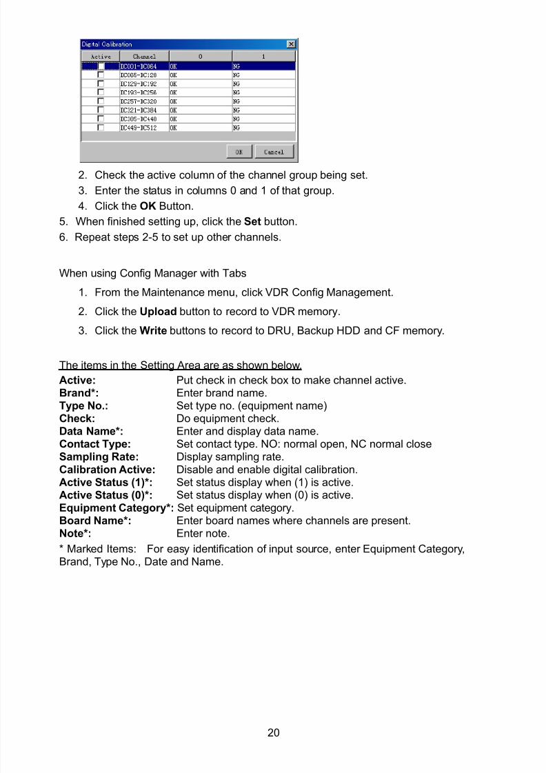
8102019 Ome44376d Vr3000 Mainte Cof26amp3bmol
httpslidepdfcomreaderfullome44376d-vr3000-mainte-cof26amp3bmol 2257
20
2 Check the active column of the channel group being set
3 Enter the status in columns 0 and 1 of that group
4 Click the OK Button
5 When finished setting up click the Set button
6 Repeat steps 2-5 to set up other channels
When using Config Manager with Tabs
1 From the Maintenance menu click VDR Config Management
2 Click the Upload button to record to VDR memory
3 Click the Write buttons to record to DRU Backup HDD and CF memory
The items in the Setting Area are as shown below
Active Put check in check box to make channel activeBrand Enter brand name
Type No Set type no (equipment name)Check Do equipment checkData Name Enter and display data nameContact Type Set contact type NO normal open NC normal closeSampling Rate Display sampling rateCalibration Active Disable and enable digital calibrationActive Status (1) Set status display when (1) is activeActive Status (0) Set status display when (0) is activeEquipment Category Set equipment categoryBoard Name Enter board names where channels are presentNote Enter note
Marked Items For easy identification of input source enter Equipment CategoryBrand Type No Date and Name
8102019 Ome44376d Vr3000 Mainte Cof26amp3bmol
httpslidepdfcomreaderfullome44376d-vr3000-mainte-cof26amp3bmol 2357
21
26 Audio
Microphone and VHF audio settings are performed in the Audio tab
Set the items in the Audio tab as shown below
1 Click the Audio tab
2 Select channel from the Information Area3 Click Select Equipment in the Setting Area
4 Click on the connected device in the indicated channel The setting contents aredisplayed in the Information and Setting Areas
5 If required update the item contents in the Setting Area Refer to the detailed itemexplanation below
6 After completing settings for a channel click the Set buttonNote Be sure to click the Set button before moving to another channel
7 Repeat steps 2-6 to set up other channels
8102019 Ome44376d Vr3000 Mainte Cof26amp3bmol
httpslidepdfcomreaderfullome44376d-vr3000-mainte-cof26amp3bmol 2457
22
When using Config Manager with tabs
1 From the Maintenance menu click VDR Config Management
2 Click the Upload button to record to VDR memory
3 Click the Write buttons to record to DRU Backup HDD and CF memory
MIC testDo the MIC test to check whether audio is received clearly in adequate level or not
1 Click the MIC TEST button in the Setting Area
2 Click the TEST button in the MIC Test dialogue box MIC test results are displayed in
the MIC Test dialogue box
3 Click the Close button to close the dialogue box
Note Not the same recordingplayback function as the previous Web Configuratorsoftware
Continuous MIC TestRun the continuous MIC test as needed accordingly
1 Click the Continuous MIC Test button in the Setting Area2 Set up how many times to perform in the Continuous MIC Test dialogue box and click
the Test button
3 Click the Close button to close the dialogue box
8102019 Ome44376d Vr3000 Mainte Cof26amp3bmol
httpslidepdfcomreaderfullome44376d-vr3000-mainte-cof26amp3bmol 2557
23
Active Put check in check box to make channel activeBrand Enter and display brand nameType No Set type no (equipment name)Check Do equipment checkData Name Enter data nameInput Type Enter input type Sampling Data Bit Displays sampling data bit rate
Sampling Frequency Displays Sampling FrequencyCodec Sets MIC typeMIC Test Active M1M3M5 Put a checkmark when performing MIC Test of M1M3M5MIS Test Active M2M4M6 Put a checkmark when performing MIC Test of M2M4M6 MIC M1M3M5 Position Enter MIC position of MIC M1M3M5MIC M2M4M6 Position Enter MIC position of MIC M2M4M6Threshold Level M1M3M5 Enter MIC test threshold level of MIC M1M3M5Threshold Level M2M4M6 Enter MIC test threshold level of MIC M2M4M6Equipment Category Set equipment categoryBoard Name Enter board names where channels are present
Note Enter note Marked Items For easy identification of input source enter Equipment Category BrandType No Date and Name
8102019 Ome44376d Vr3000 Mainte Cof26amp3bmol
httpslidepdfcomreaderfullome44376d-vr3000-mainte-cof26amp3bmol 2657
24
27 Alarm
Alarm and Alarm Status settings are found in the Alarm tab
The Alarm tab shows the following information about alarms Click the Time Categoryand Name tabs in the title bar to sort
Time Time of alarm
Category Alarm categoryName Name of alarm
Number Alarm number
Status Alarm status
Alarm Search
1 Click the Search button above the Alarm tab The Search dialogue box appears
2 Add a checkmark to any desired search items (multiple items can be selected)
Start Time Display name of alarms generated after a certain time
End Time Display name of alarms generated before a certain time
Name Display information for alarm name entered
8102019 Ome44376d Vr3000 Mainte Cof26amp3bmol
httpslidepdfcomreaderfullome44376d-vr3000-mainte-cof26amp3bmol 2757
25
Number Display information for alarm number entered
Status Display alarm status for alarm name entered
3 In the checked items column input the desired search items
4 Click the Search Button
Close the Search box to cancel a search
Note During a search the upper left Mode changes from Play to Search andDisplay search related information
8102019 Ome44376d Vr3000 Mainte Cof26amp3bmol
httpslidepdfcomreaderfullome44376d-vr3000-mainte-cof26amp3bmol 2857
26
28 Event
Click the items shown below to sort by item selected
Note You can sort the items in ascending order () descending order () and
initialization order (no symbol)
Time Time an event occurred
Category Category of an event
Name Name of an event
Contents1 Display data associated with log
Contents2 Display data associated with log
Event Search
Do the following to search events
1 Click the Search button on the upper right of the Event tab
2 In the dialogue box add a checkmark to desired search items Multiple items can bechecked
Start Time Display name of event generated after a certain time
End Time Display name of event generated before a certain time
Name Display event names entered
Number Display event numbers entered
Status Display event status entered
Enter information about the checked event to search in the character input box
3 Click the Search button
Note The mode changes from Play to Search when performing a search
8102019 Ome44376d Vr3000 Mainte Cof26amp3bmol
httpslidepdfcomreaderfullome44376d-vr3000-mainte-cof26amp3bmol 2957
27
29 Hardware
The Hardware tab provides information about the system hardware
The buttons in the Setting window work as follows
Self Check Status Display status of self check
CPU Display information about the CPU
Memory Size Display memory size
CPU Board Display status of CPU board
Audio Board Display status of Audio board
Serial Board Display status of Serial board
Radar Interface Board Display status of Radar Interface boardNote Enter and display note
Marked items are optional
8102019 Ome44376d Vr3000 Mainte Cof26amp3bmol
httpslidepdfcomreaderfullome44376d-vr3000-mainte-cof26amp3bmol 3057
28
210 JB
Connect the Junction Box to the DCU before turning on the system
The JB tab functions to set up the Junction Box
The basic procedure for setting up the Junction Box is as follows
1 Click the JB tab2 Select a Junction Box from the Information Area
3 Set up the Junction Box from the Setting Area
4 Click the Set button (Be sure to do this before moving to another channel)5 Click the Check button to perform an inspection on all channels In the Information
Area check column either OK or NG (No Good) is displayed
When using Config Manager with Tabs
1 From the Maintenance menu click VDR Config Management
2 Click the Upload button to record to VDR memory
3 Click the Write buttons to record to DRU Backup HDD and CF
The items in the Setting window work as followsActive Put check in check box to make channel activeNo Display Junction Box numberIP Address Display IP address of Junction Box acquired by VDRMAC Address Display MAC address of Junction Box acquired by VDRCheck Enable and disable equipment checkNote Enter note
Marked items are optional
8102019 Ome44376d Vr3000 Mainte Cof26amp3bmol
httpslidepdfcomreaderfullome44376d-vr3000-mainte-cof26amp3bmol 3157
29
211 Life Time
The Life Time tab controls consumable parts
The basic procedure for using the Life Time tab is as follows
1 Click the Life Time tab
2 Select a Type No in the Information Area3 Set up the chosen part from Setting Area
4 Click the Set button
Note Be sure to click the Set button before moving to set up a different Type
The items in the Setting window work as follows
Type No Enter and display type no
Data Name Enter and display data name
Level Set replacement level Legal Exchange Parts or Normal Exchange Parts
Replace Date Enter and display recommended day of replacement
Lifetime Term Not usedNote Enter and display note
The Status column of the Information Area displays as follows
OK The recommended date of replacement shown in the Replace Date
box in the Information window has not passed
Out of Date The date of replacement has passed
None The date of replacement has not been set
8102019 Ome44376d Vr3000 Mainte Cof26amp3bmol
httpslidepdfcomreaderfullome44376d-vr3000-mainte-cof26amp3bmol 3257
30
212 Network
The Network tab sets the system network
The basic procedure for setting up the system network is as follows
1 Click the Network tab
2 Select a port from the Information Area
3 Set up the network from the Setting Area
4 Click the Set button
Note1 Be sure to click the Set button before moving to set up a different Port
Note2 After setting the system network reboot the VDR to apply the settings
The items in the Setting window work as follows
LAN Type Enter LAN type Public LAN or JB LAN
MAC Address Enter MAC address
IP Address Enter IP address
Subnet Mask Enter subnet mask
Gateway Address Enter gateway address
Live Play Multicast Mode (Only JB LAN) Check box to enable live player multicast
mode
Multicast Address (Only Public LAN) Enter and display live player multicast addressNote Enter note
Marked items are optional
8102019 Ome44376d Vr3000 Mainte Cof26amp3bmol
httpslidepdfcomreaderfullome44376d-vr3000-mainte-cof26amp3bmol 3357
31
213 System
The System tab sets system related functions
The basic procedure for using the System tab is as follows
1 Click the System tab
2 Set up the chosen item from the Setting Area
3 Click the Set button
Note Be sure to click the Set button before moving to a different tab
The items in the Setting window work as follows
VDR Type Enter type of VDR
VDR Model Enter model number of VDR
Radar Interface Check Enable and disable checking of the Radar Interface board
Junction Box Count Enter number of junction boxes in system
DRU Flash Count Enter number of DRU flash disks in system Set 1 when DRU
serial no is 5000 and more Set 3 when DRU serial no is less
than 5000
DRU Capacity Display capacity of DRU
Backup HDD Capacity Display capacity of Backup HDD
VDR Config Version Display version no of VDR
VDR Config Date Display the number of hours the VDR settings have
been saved
VDR Config Code Display configuration identity code
Installation Engineer Enter name of the equipment installer
Installation Company Enter name of installers company
8102019 Ome44376d Vr3000 Mainte Cof26amp3bmol
httpslidepdfcomreaderfullome44376d-vr3000-mainte-cof26amp3bmol 3457
32
Installation Date Enter the date of the installation
MIC Test Time Enter the date of the MIC test
Note Enter note Marked items are optional
USB memory logging Do not check Enable
IEEE1394 BUS Error Auto Restart function Not used
IEEE1394 Active Node Count Do not change the default value of 3 (However set to 5
for serial number 5000 or less of DRU)
IEEE1394 Recover Process Limit Count Do not change the default value of 10
DRU Error Auto Restart function Not used
REBOOT DELAY TIME (sec) Do not change the default value of 10
LIMIT REBOOT COUNT Do not change the default value of 10
Live Player Max Connection Count The max number of Live Player V4 that can be
connected simultaneously The default no is two
but a maximum of five can be set here After you
change this option reboot the VDR to apply the
setting Disconnect the cable connected with
Live Player V4 (PC) from the VDR and thenreconnect it
214 Software
The Software tab sets and display software-related operations
The basic procedure for using the Software tab is as follows
1 Click the Software tab
2 Set up the chosen Item from the Setting Area
3 Click the Set button
8102019 Ome44376d Vr3000 Mainte Cof26amp3bmol
httpslidepdfcomreaderfullome44376d-vr3000-mainte-cof26amp3bmol 3557
33
The items in the Setting window work as follows
VDR System Program Display the VDR system program no
Process Version Display the process version
Power Distribution Unit (PDU) Display the version no of the PDU
Operation System Display the version no of the OS
Audio Driver Display the version no of the audio driverRAP Version Enter the version no of the RAP
AP Version Enter the version no of the AP
JB1-8 Boot Program Display the no of the RJB Boot program for Junction Boxes
1 to 8
JB1-8 App Program Display the no of the RJB App program for Junction Boxes
1 to 8
Watch Dog Interval Do not change the default value of 60 (Enter the process
response time A process is repeated if there is no response
within the time interval set here)
Giveup Interval Do not change the default value of 300 (Enter the restart
watch time The restarting of a process is stopped when the
number of times it has been restarted is exceeded within the
interval set here)
Refork Limit Do not change the default value of 10 (Enter the upper limit
for process restart The restarting of a process is stopped
when the number of times it has been restarted exceeds the
Give up Interval)
Note Enter note
Marked Items are optional
8102019 Ome44376d Vr3000 Mainte Cof26amp3bmol
httpslidepdfcomreaderfullome44376d-vr3000-mainte-cof26amp3bmol 3657
34
215 GPS
The GPS tab sets GPS-related parameters
The basic procedure for using the GPS tab is as follows
1 Click the GPS tab
2 Set up the chosen channel from the Information window3 Set up the chosen item in the Setting Area
4 Click the Set button
5 Repeat steps 2-4 to set up each Channel
6 Click the Check button to perform an inspection on all channels In the Information Area check column either OK or NG (No Good) is displayed
The items in the Setting window work as follows
Priority Display priority order
Date and Time SourceShip Position Source Set GPS source channel (serial channel
number for ZDA sentence)
Check Enable and disable checking
GPS Antenna Position From Bow Enter position of GPS antenna from bow
GPS Antenna Position From Stern Enter position of GPS antenna from stern
GPS Antenna Position From Port Enter position of GPS antenna from port
GPS Antenna Position From Starboard Enter position of GPS antenna from starboard
GPS Failure Threshold If the ZDA is input within the set time limit
the system restarts synchronized If not
input within the time limit the system restarts
without synchronization
8102019 Ome44376d Vr3000 Mainte Cof26amp3bmol
httpslidepdfcomreaderfullome44376d-vr3000-mainte-cof26amp3bmol 3757
35
GPS Delay Time by Time Sync Enter minimum time delay for time
synchronization Time synchronization is started
only in the time set here
GPS Difference Interval The time set here is added to the GPS time to
synchronize the system time Leave at the default
0 value setting
GPS Sync Giveup Time If the system receives the GPS time within the
time set the system synchronizes with the time
When not receiving a signal the system displays
an ldquoerror 26rdquo message
ZDA Timeout Enter value (seconds) for ZDA timeout (234 error)
from GPS
Note Enter and display note
Marked Items are optional
216 VesselThe Vessel tab sets and displays own ships information such as name and IMO number
The basic procedure for using the Vessel tab is as follows
1 Click the Vessel tab
2 Set up information in the Setting window
3 Click the Set button (Be sure to do this before moving to another port)
4 From the Maintenance menu click VDR Config Management and then Config5 Click the Write buttons to save data to the DRU backup HDD CF
The buttons in the Setting window works as follows
Vessel Name Enter name of vessel
Vessel IMO Number Enter IMO number of vessel
Vessel Flag Enter flag of vessel
Approval of Authority Enter name of approving authority
Note Enter note
Marked items are optional
8102019 Ome44376d Vr3000 Mainte Cof26amp3bmol
httpslidepdfcomreaderfullome44376d-vr3000-mainte-cof26amp3bmol 3857
36
217 Delivery
The Delivery tab functions to transmit data from the VDR to a PC via Ethernet LAN Do
not use this function during live connection
The basic procedure for using the Delivery tab is as follows
1 Click the Delivery tab
2 Click the Add button to show the Delivery Config window
3 Select protocol from the Protocol drop-down box (Unicast or Multicast)
4 Enter IP address in the IP address input box
5 Enter port number in the port number input box
6 Click the tab of the data to send (Analog Digital or Serial)
7 Select the channel of the data to send
8 If Serial was selected at step 6 select applicable data sentence from the Inactivewindow Click the right arrow to move the data sentence to the Active window
9 Click the OK button to close the Delivery Config window
10 The settings are listed in a table in the Delivery window Check the checkbox in the
Active column and then click the Set button
The buttons in the Setting window works as follows
Set Save edited settings
Add Create new delivery settings
Modify Modify selected delivery settings
Delete Delete selected delivery settings
8102019 Ome44376d Vr3000 Mainte Cof26amp3bmol
httpslidepdfcomreaderfullome44376d-vr3000-mainte-cof26amp3bmol 3957
37
3 How to Back up Configuration DataThis chapter shows how to back up configuration data to various storage media
Configuration data can be opened with Word Pad or any text editor other than Notepad
31 How to Back up Configuration Data to the Startup CompactFlash (CF)
Back up data to the startup CF after setting the VDR Configuration data is created on the
CF as a configini file
Note When the error shown below occurs during the downloading or uploading of
configuration data check the connection of the DRU Backup HDD and CF and then
upload or download the configuration data again
[CONN] Download failed
[CONN] Could not upload config file
If error occurs again re-install the VDR Maintenance Viewer
Do the following to back up data to a CF
1 Set up parameters on the tabs referring to Chapter 2
2 Click the Maintenance menu
3 Select VDR Config Management
4 Click the Upload button
5 A confirmation box appears click the OK button to start uploading to the VDR
6 Click the Write button where the arrow connects between VDR and DRU BackupHDD
7 A confirmation window appears click the OK button to save the configuration data tothe DRU and Backup HDD
8102019 Ome44376d Vr3000 Mainte Cof26amp3bmol
httpslidepdfcomreaderfullome44376d-vr3000-mainte-cof26amp3bmol 4057
38
8 Click the Write button where the arrow connects between the VDR and CF
9 A confirmation window appears click the OK button to save the configuration data tothe startup CF
10 Check that the PC VDR DRU Backup HDD and CF share the same VDR configcode
32 How to Back up Configuration Data to a PC
Configuration data saved to the PC can be edited with Wordpad and shared with other
vessels For future service ease it is recommended to backup configuration data to the
PC and have the data on board the vessel Also it is recommended to upload this data to
Furuno SMS (Service Management System) If unable to upload to Furuno SMS please
contact the Service Center Furuno Japan
To back up configuration data to the PC do as follows
1 Set up parameters on the tabs referring to Chapter 2
2 Click the Maintenance menu
3 Select VDR Config Management
4 Click the Export to button
5 A confirmation window appears click the OK button
6 Select where to save the data enter file name then click the Open button
7 Confirm that back up file is in the location selected
33 How to restore the default settings
Click the Default button on the VDR Config Management window to restore the default
settings of the DRU Backup HDD CF and VDR Maintenance Viewer
8102019 Ome44376d Vr3000 Mainte Cof26amp3bmol
httpslidepdfcomreaderfullome44376d-vr3000-mainte-cof26amp3bmol 4157
39
4 How to Upload Configuration Datafrom a PCThe procedure below shows how to upload configuration from the PC to aVR-3000VR-3000S
1 Click the Maintenance menu
2 Select VDR Config Management
3 Click the Import from button
4 The Open window appears Select configuration data and then click the Open button
5 Click the Upload button to upload data to the VR-3000VR-3000S
6 Click the Write buttons to save data to the DRU backup HDD and CF
8102019 Ome44376d Vr3000 Mainte Cof26amp3bmol
httpslidepdfcomreaderfullome44376d-vr3000-mainte-cof26amp3bmol 4257
40
5 Media ManagementThe media management feature deletes data from recording media initialization the
system etc There are two method LAN connection and Direct connection The Direct
connection takes longer time than the LAN connection Basically use the LAN connection
method
Note Initialization or creation of recording media is not available when Source Select onthe Live Player V4 is selected to Backup HDD
51 Initialization
This section shows how to delete data from the recording media Configuration data is
not deleted After performing the software configuration delete the data from the DRU
and HDD
Do the following to delete data from the DRU (LAN connection)
1 Set the PlaybackCPU switch in the DCU to the CPU position
2 Use an Ethernet cross cable to connect the PC to J14 (DATA) in the DCU (See page5)
3 Open the Tool menu
4 Select Media Management to open the VDR Media Management window
5 Check that IP address shown in the ldquoLAN Connect to IPrdquo in VDR Media Table Area isthe same as the IP address access point
6 Select ldquoLAN Connect to IPrdquo in the VDR Media Table column
8102019 Ome44376d Vr3000 Mainte Cof26amp3bmol
httpslidepdfcomreaderfullome44376d-vr3000-mainte-cof26amp3bmol 4357
41
7 Click the Analyze button A list of recording media connected to the VDR appears
Put a checkmark in the checkbox of the Select column for the DRU in the Name columnNote If there are several flash memories in the DRU all flash memories are shownCheck all flash memories shown
8 Select ldquoDRU Initializerdquo from the Operation dropdown list in the Operation area
10 Click the Run button
Do the following to delete data from the DRU (Direct connection)
1 Start Live Player V4 software
2 Open the Tool menu and select Source Select Select Live from the pull-downmenu
3 Click the Alarm tab and open Alarm History
4 Set the PlaybackCPU switch in the DCU to the Playback position
5 Wait approx 10 minutes and confirm that Alarm 174 occurs on Alarm History of LivePlayer V4
6 Connect an IEEEE1394 cable between J6 in the DCU and the PC
7 Open the Tool menu
8 Select Media Management to show the VDR Media Management window
9 Select Direct in the VDR Media Table column
10 Click the Analyze button A list of recording media connected to the VDR appears
11 Put a checkmark in the checkbox of the Select column for the DRU in the Namecolumn
Note If there are several flash memories in the DRU all flash memories are shownCheck all flash memories shown
12 Select ldquoDRU Initializerdquo from the Operation dropdown list in the Operation area
13 Enter password in the password column
14 Click the RUN button
8102019 Ome44376d Vr3000 Mainte Cof26amp3bmol
httpslidepdfcomreaderfullome44376d-vr3000-mainte-cof26amp3bmol 4457
42
Delete data from the Backup HDD as follows (LAN connection)
1 Set the PlaybackCPU switch in the DCU to the CPU position
2 Check that an Ethernet cross cable is connected between J14 in the DCU and the PC
3 Open the Tool menu
4 Select Media Management to open the VDR Media Management window
5 Check that IP address shown in the LAN Connect to IP in VDR Media Table Area is
the same as the IP address access point6 Select LAN Connect to IP in the VDR Media Table column
7 Click the Analyze button
8 A list of recording media connected to the VDR appears
9 Put a checkmark in the box of the Select column for the Backup HDD in the Namecolumn Select ldquoBackup HDD Initializerdquo from the Operation dropdown list in theOperation area
10 Click the Run button
Delete data from the Backup HDD as follows (Direct connection)
1 Start Live Player V4 software
2 Open the Tool menu and select Source Select Select Live from the pull-downmenu
3 Click the Alarm tab and open Alarm History
4 Set the PlaybackCPU switch in the DCU to the Playback position
5 Wait approx 10 minutes and confirm that Alarm 174 occurs on Alarm History of LivePlayer V4
6 Connect an IEEE1394 cable between J6 in the DCU and the PC
7 Open the Tool menu
8 Select Media Management to open the VDR Media Management window9 Select Direct in the VDR Media Table window
10 Click the Analyze button A list of recording media connected to the VDR appears
11 Put a checkmark in the check box of the Select column for the Backup HDD in theName column Select ldquoBackup HDD Initializerdquo from the Operation dropdown list in theOperation area
12 Enter password
13 Click the Run button
8102019 Ome44376d Vr3000 Mainte Cof26amp3bmol
httpslidepdfcomreaderfullome44376d-vr3000-mainte-cof26amp3bmol 4557
43
52 CreationThe Creation feature initializes recording media
Note1 This feature deletes ALL configuration data Backup all VDR configuration data
Note2 When you initialize medium that is a different format for the DRU or Backup HDDdelete all partitions with the disk management tool of Windows
Note3 When the Creation is failed try again If you can not initialize recording media tryunder condition as shown below
Do the Creation by the direct connection (When the Creation by the LAN
connection is failed)
Delete all partitions of the DRU or Backup HDD with the disk management tool of
Windows to do the Creation
If the Creation is still failed request service to repairreplace the DRU or Backup
HDD
Initialize the DRU as follows (LAN connection)
1 Set the PlaybackCPU switch in the DCU to the CPU position
2 Check that an Ethernet cross cable is connected between J14 in the DCU and the PC
3 Open the Tool menu
4 Select Media Management to open the VDR Media Management window
5 Check that IP address shown in the LAN Connect to IP in VDR Media Table Area isthe same as the IP address access point
6 Check ldquoLAN Connect to IPrdquo in the VDR Media Table column
7 Click the Analyze button A list of recording media connected to the VDR appears
8 Put a checkmark in the box of the Select column for the DRU in the Name column
Select ldquoDRU Creationrdquo from the Operation dropdown list in the Operation area
9 Click the Run button
Initialize the Backup HDD as follows (LAN connection)
1 To format the Backup HDD place a checkmark in the Select column of the listedrecord media in the Name column of the VDR Media Management dialogue box
2 From the Operation drop down list of the Operation area select ldquoBackup HDDCreation (Radar) or ldquoBackup HDD Creationrdquo
Two partition tools are available for the Backup HDD in the Media Management as
below
Backup HDD creation
This tool is used when the number of the SXGA video signal connected to the BackupHDD is the same as the DRU The same partition is created on both DRU and HDD
(1) When two SXGA video signals are recorded onto the HDD while 9-GB DRU isconnected
(2) When an SXGA video signal is recorded onto the HDD while 6-GB DRU isconnected
Backup HDD creation (radar)
This tool is used when two SXGA video signals are recorded onto the HDD with 6-GB
DRU connected The HDD has an area (radar) to record the second radar signal inaddition to the same partition as the DRU This tool cannot be used when 9-GB DRUis connected
3 Press the Run Button
8102019 Ome44376d Vr3000 Mainte Cof26amp3bmol
httpslidepdfcomreaderfullome44376d-vr3000-mainte-cof26amp3bmol 4657
44
Initialize the DRU as follows (Direct connection)
1 Start Live Player V4 software
2 Open the Tool menu and select Source Select Select Live from the pull-downmenu
3 Click the Alarm tab and open Alarm History
4 Set the PlaybackCPU switch in the DCU to the Playback position
5 Wait approx 10 minutes and confirm that Alarm 174 occurs on Alarm History of LivePlayer V4
6 Connect an IEEE1394 cable between J6 in the DCU and the PC
7 Open the Tool menu
8 Select Media Management to open the VDR Media Management window
9 Select Direct in the VDR Media Table window
10 Click the Analyze button A list of recording media connected to the VDR appears
11 Put a checkmark in the box of the Select column for the DRU and the desiredrecording media in the Name column In the Operation dropdown list of the Operationarea select ldquoDRU Creationrdquo
12 Enter password in the password column
13 Click the Run button
Initialize the Backup HDD as follows (Direct Connection)
1 To format the Backup HDD place a checkmark in the Select column of the listedrecord media in the Name column of the VDR Media Management dialogue box
2 From the Operation column of the Operation area select ldquoBackup HDD Creation(Radar) or ldquoBackup HDD Creationrdquo
Backup HDD creation
This tool is used when the number of the SXGA video signal connected to the BackupHDD is the same as the DRU The same partition is created on both DRU and HDD
(1) When two SXGA video signals are recorded onto the HDD while 9-GB DRU is
connected
(2) When an SXGA video signal is recorded onto the HDD while 6-GB DRU is
connected
Backup HDD creation (radar)
This tool is used when two SXGA video signals are recorded onto the HDD with 6-GBDRU connected The HDD has an area (radar) to record the second radar signal inaddition to the same partition as the DRU This tool cannot be used when 9-GB DRUis connected
3 Enter the password in the Password column
4 Press the Run Button
8102019 Ome44376d Vr3000 Mainte Cof26amp3bmol
httpslidepdfcomreaderfullome44376d-vr3000-mainte-cof26amp3bmol 4757
45
53 How to Enable Recording Area on the Backup HDD
This function enables writing over a recording area To prevent falsification of data all
recording areas must be saved otherwise this function is disabled To use this function push
the SAVE button Save the data before doing this procedure
Note Software version 135 or higher can enable writing over a recording area even if
all recording areas are not saved
Recording enable (LAN connection)
1 Set the PlaybackCPU switch in the DCU to the CPU position
2 Check that an Ethernet cross cable is connected between J14 in the DCU and the PC
3 Open the Tool menu
4 Select Media Management to open the VDR Media Management window
5 Check that IP address shown in the ldquoLAN Connect to IPrdquo in VDR Media Table Area isthe same as the IP address access point
6 Select ldquoLAN Connect to IPrdquo in the VDR Media Table column7 Click the Analyze button A list of recording media connected to the VDR appears
8 Put a checkmark in the box of the Select column for the Backup HDD in the Namecolumn
9 Select ldquoBackup HDD Recording Area Enablerdquo from the Operation dropdown list in theOperation area
10 Click the Run button
Recording enable (Direct connection)
1 Start Live Player V4 software
2 Open the Tool menu and select Source Select Select Live from the pull-down menu3 Click the Alarm tab and open Alarm History
4 Set the PlaybackCPU switch in the DCU to the Playback position
5 Wait approx 10 minutes and confirm that Alarm 174 occurs on Alarm History of LivePlayer V4
6 Connect an IEEE1394 cable between J6 in the DCU and the PC
7 Open the Tool menu
8 Select Media Management to open the VDR Media Management window
9 Select Direct in the VDR Media Table window
10 Click the Analyze button A list of recording media connected to the VDR appears11 Put a checkmark in the box of the Select column for the Backup HDD in the Name
column
12 Select ldquoBackup HDD Recording Area Enablerdquo from the Operation dropdown list in theOperation area
13 Enter password
14 Click the Run button
8102019 Ome44376d Vr3000 Mainte Cof26amp3bmol
httpslidepdfcomreaderfullome44376d-vr3000-mainte-cof26amp3bmol 4857
46
6 Other Functions
61 Software Management
The software download feature downloads VDR system software to the PC
To download software
1 Click the Maintenance menu
2 From the Software Management menu click Software Download to show theSoftware Download window
3 Enter the IP address 1000100 in the IP address box in the Update Server area
4 Click the Download Software button
5 The confirmation window appears click the OK button
The Software Backup Execute window shows the results of the download
Software is downloaded to C Program Files VDR Viewer Viewer Backup The software file
name is vdrtar
To Update Software
VDR system program version 16x can update the software with the procedure shownbelow
Note Do not update the file downloaded in procedures above
1 Click the Maintenance menu
2 From the Software Management menu click Software Upload to show the SoftwareUpload area
3 Click the Select button to show the Open window
4 Select update file (vdrtar) and click the Open button
8102019 Ome44376d Vr3000 Mainte Cof26amp3bmol
httpslidepdfcomreaderfullome44376d-vr3000-mainte-cof26amp3bmol 4957
47
5 Check the displayed Software information is correct
6 Enter the IP address 1000100 in the IP address box in the Update Server area
7 Enter password
8 Click the Update button
After the updating is completed the VDR is automatically restarted
Note Click the Restore button on the Software Update window to restore previoussoftware version This feature is available after updating the software
62 Password Management
The password can be changed for a serviceman to access the equipment Contact
FURUNO to get the default password to use during installation
Serviceman password
1 Click the Maintenance menu2 Select Change Serviceman Password from Password Management to show the
Change Serviceman Password window
3 Enter current password in the Old Password box
4 Enter the new password in the New Password box of the Change Password area
5 Enter new password again in the Confirm New Password box
6 Click the OK button
Audio password
The audio password set at the VDR Maintenance Viewer can be removed to enable
audio access without password1 Click the Maintenance menu
2 Select Change Audio Password from Password Management to show the Change Audio Password window
3 The confirmation window appears click the OK button
8102019 Ome44376d Vr3000 Mainte Cof26amp3bmol
httpslidepdfcomreaderfullome44376d-vr3000-mainte-cof26amp3bmol 5057
48
63 Record ComparisonThe integrity of the DRU and Backup HDD recordings can be compared This function isused by the RampD engineer for debugging
Follow the procedure as shown below
1 Click the Maintenance menu2 Select Record Comparison to show the Record Comparison window
The results are shown every 15 seconds in the Record Comparison window
8102019 Ome44376d Vr3000 Mainte Cof26amp3bmol
httpslidepdfcomreaderfullome44376d-vr3000-mainte-cof26amp3bmol 5157
49
64 Software History
This section shows you to save and configure software history (communications record)
How to save software history
Note When the error dialog appears while saving the software history restart the VDR
Maintenance Viewer
1 Click the Maintenance menu
2 Select Software History Collect
3 Click the Select button The Open dialog box appears
4 Select where to save the data then click the Open button
5 Select desired save condition then click the OK buttonNone No savingAt Once Save the software history manually Saving begins as soon as the OK button is clickedPeriodic For debugging Do not use otherwise The intervals are 30 sec 60 secand 120 secAlarm Detection For debugging Do not use otherwise Software history is savedwhen specified alarm is released Enter alarm number
How to configure software communications record
The RampD engineer uses this function for debugging Do not do this procedure unless
required Malfunction can result
1 Click the Maintenance menu
2 Select Software History Config
3 Do the followingProcess Select the type of communications record to save ALL saves allcommunications records
Detail Hide or show detailed information4 Click the Send button
8102019 Ome44376d Vr3000 Mainte Cof26amp3bmol
httpslidepdfcomreaderfullome44376d-vr3000-mainte-cof26amp3bmol 5257
50
65 Easy SetupThis feature sets equipment settings in batch and creates a data file of those settings
Default template The default template is created with the settings entered at installation
1 Click the Maintenance menu
2 Select Easy Setup to show the Template Selection window
3 Select Default Template
4 Click the Start button to show the Easy Setup window
5 Right click the channels (Radar Audio Digital Serial Analog) then select Edit toshow the Equipment Selection window
6 From the Equipment Directory window select equipment connected to the selectedchannel and then click the OK button
7 Repeat steps 5 and 6 to select equipment settings for each channel
8 Click the Save button in the Easy Setup window to show the Save window
9 Select where to save the file and enter file name
10 Click the Save button
8102019 Ome44376d Vr3000 Mainte Cof26amp3bmol
httpslidepdfcomreaderfullome44376d-vr3000-mainte-cof26amp3bmol 5357
51
Specific template Use a file already created
1 Click the Maintenance menu
2 Select Easy Setup to show the Template Selection window
3 Check Specified Template
4 Click the Select button and then select the file to edit
5 Click the Start button to show the Easy Setup window
6 Right click the channels (Radar Audio Digital Serial Analog) then select Edit toshow the Equipment Selection window
7 From the Equipment Directory window select equipment connected to the selectedchannel and then click the OK button
8 Repeat steps 6 and 7 to select equipment settings for each channel
9 Click the Save button in the Easy Setup window to show the Save window
10Select where to save the file and enter file name
11 Click the Save button
66 Equipment Management
This feature controls the import and export of equipment settings
Import data file
Import data files of equipment settings created in Easy Setup etc to the VDR
1 Click the Maintenance menu
2 Select Import from Equipment Management to show the Open window
3 Select the data file to import and click Open
Export data file
Export data files of equipment settings from the VDR to a PC
1 Click the Maintenance menu
2 Select Export from Equipment Management to show the Save window
3 Enter file name
4 Click the Save button
8102019 Ome44376d Vr3000 Mainte Cof26amp3bmol
httpslidepdfcomreaderfullome44376d-vr3000-mainte-cof26amp3bmol 5457
52
67 PC_RAP
This feature enables the same operation of the RAP (Remote Alarm Panel) from a PC
Select PC_RAP from the Tool menu to show the PC_RAP window
The buttons in the PC_RAP window function as shown below
SAVE Stop recording in the area where recording is currently being done
ACK Silence audio alarm
The PC_RAP display shows the following information with LEDs
RAP_LEDs Display the status of LEDs on the RAPSave The Save button blinks yellow when pushed When the 4 memory
areas have data recorded to them the Save button lights orange when
pushed
Normal Lights (green) where there are no unconfirmed or not restored
alarms
Error Flashes (red) for not confirmed alarm Lights (red) for unrestored
alarm
8102019 Ome44376d Vr3000 Mainte Cof26amp3bmol
httpslidepdfcomreaderfullome44376d-vr3000-mainte-cof26amp3bmol 5557
53
Backup HDD Information Display status of backup HDD
Selected Display current recording area and its status in green for
normal operation and in red for abnormal operation
Size Display capacity of backup HDD
Alarm area displays unconfirmed alarms
Time Display time alarm was generatedNumber Display number of alarm
Name Display name of alarm
Pending Alarm displays the unrestored alarms out of confirmed alarms only
Time Display time alarm was generated
Number Display number of alarm
Name Display name of alarm
8102019 Ome44376d Vr3000 Mainte Cof26amp3bmol
httpslidepdfcomreaderfullome44376d-vr3000-mainte-cof26amp3bmol 5657
54
68 Other
Status Monitor
The status monitor feature provides comprehensive data about the status of the VDR
From the menu bar click Toolgt Status Monitor to show the Status Monitor window
The buttons in the Status Monitor window work as shown below
Reload Settings for automatic refreshing of the status monitor
ON Turn automatic refresh OFF
OFF The Status Monitor is refreshed every five seconds
Save Available when Reload ON is selected The contents of the Status Monitor can be
saved to a text fileUpdate Update the Status Monitor display
Close Close the Status Monitor display
8102019 Ome44376d Vr3000 Mainte Cof26amp3bmol
httpslidepdfcomreaderfullome44376d-vr3000-mainte-cof26amp3bmol 5757
VDR Error List
This feature compiles all the errors shown on the RAP for easy reference
Access from MenugtToolgtVDR Error List
The VDR error list contains the following information
NO Display the number of the error
Title Display the name of the error
Detail Display details about the error
Exchange Check
This feature removes the alarms generated when replacing the DRU or backup HDD
Access MenugtToolgtExchange Check select either DRU or Backup HDD and click OK
Reboot
Reboot the VDR
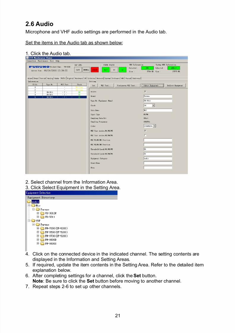
8102019 Ome44376d Vr3000 Mainte Cof26amp3bmol
httpslidepdfcomreaderfullome44376d-vr3000-mainte-cof26amp3bmol 2357
21
26 Audio
Microphone and VHF audio settings are performed in the Audio tab
Set the items in the Audio tab as shown below
1 Click the Audio tab
2 Select channel from the Information Area3 Click Select Equipment in the Setting Area
4 Click on the connected device in the indicated channel The setting contents aredisplayed in the Information and Setting Areas
5 If required update the item contents in the Setting Area Refer to the detailed itemexplanation below
6 After completing settings for a channel click the Set buttonNote Be sure to click the Set button before moving to another channel
7 Repeat steps 2-6 to set up other channels
8102019 Ome44376d Vr3000 Mainte Cof26amp3bmol
httpslidepdfcomreaderfullome44376d-vr3000-mainte-cof26amp3bmol 2457
22
When using Config Manager with tabs
1 From the Maintenance menu click VDR Config Management
2 Click the Upload button to record to VDR memory
3 Click the Write buttons to record to DRU Backup HDD and CF memory
MIC testDo the MIC test to check whether audio is received clearly in adequate level or not
1 Click the MIC TEST button in the Setting Area
2 Click the TEST button in the MIC Test dialogue box MIC test results are displayed in
the MIC Test dialogue box
3 Click the Close button to close the dialogue box
Note Not the same recordingplayback function as the previous Web Configuratorsoftware
Continuous MIC TestRun the continuous MIC test as needed accordingly
1 Click the Continuous MIC Test button in the Setting Area2 Set up how many times to perform in the Continuous MIC Test dialogue box and click
the Test button
3 Click the Close button to close the dialogue box
8102019 Ome44376d Vr3000 Mainte Cof26amp3bmol
httpslidepdfcomreaderfullome44376d-vr3000-mainte-cof26amp3bmol 2557
23
Active Put check in check box to make channel activeBrand Enter and display brand nameType No Set type no (equipment name)Check Do equipment checkData Name Enter data nameInput Type Enter input type Sampling Data Bit Displays sampling data bit rate
Sampling Frequency Displays Sampling FrequencyCodec Sets MIC typeMIC Test Active M1M3M5 Put a checkmark when performing MIC Test of M1M3M5MIS Test Active M2M4M6 Put a checkmark when performing MIC Test of M2M4M6 MIC M1M3M5 Position Enter MIC position of MIC M1M3M5MIC M2M4M6 Position Enter MIC position of MIC M2M4M6Threshold Level M1M3M5 Enter MIC test threshold level of MIC M1M3M5Threshold Level M2M4M6 Enter MIC test threshold level of MIC M2M4M6Equipment Category Set equipment categoryBoard Name Enter board names where channels are present
Note Enter note Marked Items For easy identification of input source enter Equipment Category BrandType No Date and Name
8102019 Ome44376d Vr3000 Mainte Cof26amp3bmol
httpslidepdfcomreaderfullome44376d-vr3000-mainte-cof26amp3bmol 2657
24
27 Alarm
Alarm and Alarm Status settings are found in the Alarm tab
The Alarm tab shows the following information about alarms Click the Time Categoryand Name tabs in the title bar to sort
Time Time of alarm
Category Alarm categoryName Name of alarm
Number Alarm number
Status Alarm status
Alarm Search
1 Click the Search button above the Alarm tab The Search dialogue box appears
2 Add a checkmark to any desired search items (multiple items can be selected)
Start Time Display name of alarms generated after a certain time
End Time Display name of alarms generated before a certain time
Name Display information for alarm name entered
8102019 Ome44376d Vr3000 Mainte Cof26amp3bmol
httpslidepdfcomreaderfullome44376d-vr3000-mainte-cof26amp3bmol 2757
25
Number Display information for alarm number entered
Status Display alarm status for alarm name entered
3 In the checked items column input the desired search items
4 Click the Search Button
Close the Search box to cancel a search
Note During a search the upper left Mode changes from Play to Search andDisplay search related information
8102019 Ome44376d Vr3000 Mainte Cof26amp3bmol
httpslidepdfcomreaderfullome44376d-vr3000-mainte-cof26amp3bmol 2857
26
28 Event
Click the items shown below to sort by item selected
Note You can sort the items in ascending order () descending order () and
initialization order (no symbol)
Time Time an event occurred
Category Category of an event
Name Name of an event
Contents1 Display data associated with log
Contents2 Display data associated with log
Event Search
Do the following to search events
1 Click the Search button on the upper right of the Event tab
2 In the dialogue box add a checkmark to desired search items Multiple items can bechecked
Start Time Display name of event generated after a certain time
End Time Display name of event generated before a certain time
Name Display event names entered
Number Display event numbers entered
Status Display event status entered
Enter information about the checked event to search in the character input box
3 Click the Search button
Note The mode changes from Play to Search when performing a search
8102019 Ome44376d Vr3000 Mainte Cof26amp3bmol
httpslidepdfcomreaderfullome44376d-vr3000-mainte-cof26amp3bmol 2957
27
29 Hardware
The Hardware tab provides information about the system hardware
The buttons in the Setting window work as follows
Self Check Status Display status of self check
CPU Display information about the CPU
Memory Size Display memory size
CPU Board Display status of CPU board
Audio Board Display status of Audio board
Serial Board Display status of Serial board
Radar Interface Board Display status of Radar Interface boardNote Enter and display note
Marked items are optional
8102019 Ome44376d Vr3000 Mainte Cof26amp3bmol
httpslidepdfcomreaderfullome44376d-vr3000-mainte-cof26amp3bmol 3057
28
210 JB
Connect the Junction Box to the DCU before turning on the system
The JB tab functions to set up the Junction Box
The basic procedure for setting up the Junction Box is as follows
1 Click the JB tab2 Select a Junction Box from the Information Area
3 Set up the Junction Box from the Setting Area
4 Click the Set button (Be sure to do this before moving to another channel)5 Click the Check button to perform an inspection on all channels In the Information
Area check column either OK or NG (No Good) is displayed
When using Config Manager with Tabs
1 From the Maintenance menu click VDR Config Management
2 Click the Upload button to record to VDR memory
3 Click the Write buttons to record to DRU Backup HDD and CF
The items in the Setting window work as followsActive Put check in check box to make channel activeNo Display Junction Box numberIP Address Display IP address of Junction Box acquired by VDRMAC Address Display MAC address of Junction Box acquired by VDRCheck Enable and disable equipment checkNote Enter note
Marked items are optional
8102019 Ome44376d Vr3000 Mainte Cof26amp3bmol
httpslidepdfcomreaderfullome44376d-vr3000-mainte-cof26amp3bmol 3157
29
211 Life Time
The Life Time tab controls consumable parts
The basic procedure for using the Life Time tab is as follows
1 Click the Life Time tab
2 Select a Type No in the Information Area3 Set up the chosen part from Setting Area
4 Click the Set button
Note Be sure to click the Set button before moving to set up a different Type
The items in the Setting window work as follows
Type No Enter and display type no
Data Name Enter and display data name
Level Set replacement level Legal Exchange Parts or Normal Exchange Parts
Replace Date Enter and display recommended day of replacement
Lifetime Term Not usedNote Enter and display note
The Status column of the Information Area displays as follows
OK The recommended date of replacement shown in the Replace Date
box in the Information window has not passed
Out of Date The date of replacement has passed
None The date of replacement has not been set
8102019 Ome44376d Vr3000 Mainte Cof26amp3bmol
httpslidepdfcomreaderfullome44376d-vr3000-mainte-cof26amp3bmol 3257
30
212 Network
The Network tab sets the system network
The basic procedure for setting up the system network is as follows
1 Click the Network tab
2 Select a port from the Information Area
3 Set up the network from the Setting Area
4 Click the Set button
Note1 Be sure to click the Set button before moving to set up a different Port
Note2 After setting the system network reboot the VDR to apply the settings
The items in the Setting window work as follows
LAN Type Enter LAN type Public LAN or JB LAN
MAC Address Enter MAC address
IP Address Enter IP address
Subnet Mask Enter subnet mask
Gateway Address Enter gateway address
Live Play Multicast Mode (Only JB LAN) Check box to enable live player multicast
mode
Multicast Address (Only Public LAN) Enter and display live player multicast addressNote Enter note
Marked items are optional
8102019 Ome44376d Vr3000 Mainte Cof26amp3bmol
httpslidepdfcomreaderfullome44376d-vr3000-mainte-cof26amp3bmol 3357
31
213 System
The System tab sets system related functions
The basic procedure for using the System tab is as follows
1 Click the System tab
2 Set up the chosen item from the Setting Area
3 Click the Set button
Note Be sure to click the Set button before moving to a different tab
The items in the Setting window work as follows
VDR Type Enter type of VDR
VDR Model Enter model number of VDR
Radar Interface Check Enable and disable checking of the Radar Interface board
Junction Box Count Enter number of junction boxes in system
DRU Flash Count Enter number of DRU flash disks in system Set 1 when DRU
serial no is 5000 and more Set 3 when DRU serial no is less
than 5000
DRU Capacity Display capacity of DRU
Backup HDD Capacity Display capacity of Backup HDD
VDR Config Version Display version no of VDR
VDR Config Date Display the number of hours the VDR settings have
been saved
VDR Config Code Display configuration identity code
Installation Engineer Enter name of the equipment installer
Installation Company Enter name of installers company
8102019 Ome44376d Vr3000 Mainte Cof26amp3bmol
httpslidepdfcomreaderfullome44376d-vr3000-mainte-cof26amp3bmol 3457
32
Installation Date Enter the date of the installation
MIC Test Time Enter the date of the MIC test
Note Enter note Marked items are optional
USB memory logging Do not check Enable
IEEE1394 BUS Error Auto Restart function Not used
IEEE1394 Active Node Count Do not change the default value of 3 (However set to 5
for serial number 5000 or less of DRU)
IEEE1394 Recover Process Limit Count Do not change the default value of 10
DRU Error Auto Restart function Not used
REBOOT DELAY TIME (sec) Do not change the default value of 10
LIMIT REBOOT COUNT Do not change the default value of 10
Live Player Max Connection Count The max number of Live Player V4 that can be
connected simultaneously The default no is two
but a maximum of five can be set here After you
change this option reboot the VDR to apply the
setting Disconnect the cable connected with
Live Player V4 (PC) from the VDR and thenreconnect it
214 Software
The Software tab sets and display software-related operations
The basic procedure for using the Software tab is as follows
1 Click the Software tab
2 Set up the chosen Item from the Setting Area
3 Click the Set button
8102019 Ome44376d Vr3000 Mainte Cof26amp3bmol
httpslidepdfcomreaderfullome44376d-vr3000-mainte-cof26amp3bmol 3557
33
The items in the Setting window work as follows
VDR System Program Display the VDR system program no
Process Version Display the process version
Power Distribution Unit (PDU) Display the version no of the PDU
Operation System Display the version no of the OS
Audio Driver Display the version no of the audio driverRAP Version Enter the version no of the RAP
AP Version Enter the version no of the AP
JB1-8 Boot Program Display the no of the RJB Boot program for Junction Boxes
1 to 8
JB1-8 App Program Display the no of the RJB App program for Junction Boxes
1 to 8
Watch Dog Interval Do not change the default value of 60 (Enter the process
response time A process is repeated if there is no response
within the time interval set here)
Giveup Interval Do not change the default value of 300 (Enter the restart
watch time The restarting of a process is stopped when the
number of times it has been restarted is exceeded within the
interval set here)
Refork Limit Do not change the default value of 10 (Enter the upper limit
for process restart The restarting of a process is stopped
when the number of times it has been restarted exceeds the
Give up Interval)
Note Enter note
Marked Items are optional
8102019 Ome44376d Vr3000 Mainte Cof26amp3bmol
httpslidepdfcomreaderfullome44376d-vr3000-mainte-cof26amp3bmol 3657
34
215 GPS
The GPS tab sets GPS-related parameters
The basic procedure for using the GPS tab is as follows
1 Click the GPS tab
2 Set up the chosen channel from the Information window3 Set up the chosen item in the Setting Area
4 Click the Set button
5 Repeat steps 2-4 to set up each Channel
6 Click the Check button to perform an inspection on all channels In the Information Area check column either OK or NG (No Good) is displayed
The items in the Setting window work as follows
Priority Display priority order
Date and Time SourceShip Position Source Set GPS source channel (serial channel
number for ZDA sentence)
Check Enable and disable checking
GPS Antenna Position From Bow Enter position of GPS antenna from bow
GPS Antenna Position From Stern Enter position of GPS antenna from stern
GPS Antenna Position From Port Enter position of GPS antenna from port
GPS Antenna Position From Starboard Enter position of GPS antenna from starboard
GPS Failure Threshold If the ZDA is input within the set time limit
the system restarts synchronized If not
input within the time limit the system restarts
without synchronization
8102019 Ome44376d Vr3000 Mainte Cof26amp3bmol
httpslidepdfcomreaderfullome44376d-vr3000-mainte-cof26amp3bmol 3757
35
GPS Delay Time by Time Sync Enter minimum time delay for time
synchronization Time synchronization is started
only in the time set here
GPS Difference Interval The time set here is added to the GPS time to
synchronize the system time Leave at the default
0 value setting
GPS Sync Giveup Time If the system receives the GPS time within the
time set the system synchronizes with the time
When not receiving a signal the system displays
an ldquoerror 26rdquo message
ZDA Timeout Enter value (seconds) for ZDA timeout (234 error)
from GPS
Note Enter and display note
Marked Items are optional
216 VesselThe Vessel tab sets and displays own ships information such as name and IMO number
The basic procedure for using the Vessel tab is as follows
1 Click the Vessel tab
2 Set up information in the Setting window
3 Click the Set button (Be sure to do this before moving to another port)
4 From the Maintenance menu click VDR Config Management and then Config5 Click the Write buttons to save data to the DRU backup HDD CF
The buttons in the Setting window works as follows
Vessel Name Enter name of vessel
Vessel IMO Number Enter IMO number of vessel
Vessel Flag Enter flag of vessel
Approval of Authority Enter name of approving authority
Note Enter note
Marked items are optional
8102019 Ome44376d Vr3000 Mainte Cof26amp3bmol
httpslidepdfcomreaderfullome44376d-vr3000-mainte-cof26amp3bmol 3857
36
217 Delivery
The Delivery tab functions to transmit data from the VDR to a PC via Ethernet LAN Do
not use this function during live connection
The basic procedure for using the Delivery tab is as follows
1 Click the Delivery tab
2 Click the Add button to show the Delivery Config window
3 Select protocol from the Protocol drop-down box (Unicast or Multicast)
4 Enter IP address in the IP address input box
5 Enter port number in the port number input box
6 Click the tab of the data to send (Analog Digital or Serial)
7 Select the channel of the data to send
8 If Serial was selected at step 6 select applicable data sentence from the Inactivewindow Click the right arrow to move the data sentence to the Active window
9 Click the OK button to close the Delivery Config window
10 The settings are listed in a table in the Delivery window Check the checkbox in the
Active column and then click the Set button
The buttons in the Setting window works as follows
Set Save edited settings
Add Create new delivery settings
Modify Modify selected delivery settings
Delete Delete selected delivery settings
8102019 Ome44376d Vr3000 Mainte Cof26amp3bmol
httpslidepdfcomreaderfullome44376d-vr3000-mainte-cof26amp3bmol 3957
37
3 How to Back up Configuration DataThis chapter shows how to back up configuration data to various storage media
Configuration data can be opened with Word Pad or any text editor other than Notepad
31 How to Back up Configuration Data to the Startup CompactFlash (CF)
Back up data to the startup CF after setting the VDR Configuration data is created on the
CF as a configini file
Note When the error shown below occurs during the downloading or uploading of
configuration data check the connection of the DRU Backup HDD and CF and then
upload or download the configuration data again
[CONN] Download failed
[CONN] Could not upload config file
If error occurs again re-install the VDR Maintenance Viewer
Do the following to back up data to a CF
1 Set up parameters on the tabs referring to Chapter 2
2 Click the Maintenance menu
3 Select VDR Config Management
4 Click the Upload button
5 A confirmation box appears click the OK button to start uploading to the VDR
6 Click the Write button where the arrow connects between VDR and DRU BackupHDD
7 A confirmation window appears click the OK button to save the configuration data tothe DRU and Backup HDD
8102019 Ome44376d Vr3000 Mainte Cof26amp3bmol
httpslidepdfcomreaderfullome44376d-vr3000-mainte-cof26amp3bmol 4057
38
8 Click the Write button where the arrow connects between the VDR and CF
9 A confirmation window appears click the OK button to save the configuration data tothe startup CF
10 Check that the PC VDR DRU Backup HDD and CF share the same VDR configcode
32 How to Back up Configuration Data to a PC
Configuration data saved to the PC can be edited with Wordpad and shared with other
vessels For future service ease it is recommended to backup configuration data to the
PC and have the data on board the vessel Also it is recommended to upload this data to
Furuno SMS (Service Management System) If unable to upload to Furuno SMS please
contact the Service Center Furuno Japan
To back up configuration data to the PC do as follows
1 Set up parameters on the tabs referring to Chapter 2
2 Click the Maintenance menu
3 Select VDR Config Management
4 Click the Export to button
5 A confirmation window appears click the OK button
6 Select where to save the data enter file name then click the Open button
7 Confirm that back up file is in the location selected
33 How to restore the default settings
Click the Default button on the VDR Config Management window to restore the default
settings of the DRU Backup HDD CF and VDR Maintenance Viewer
8102019 Ome44376d Vr3000 Mainte Cof26amp3bmol
httpslidepdfcomreaderfullome44376d-vr3000-mainte-cof26amp3bmol 4157
39
4 How to Upload Configuration Datafrom a PCThe procedure below shows how to upload configuration from the PC to aVR-3000VR-3000S
1 Click the Maintenance menu
2 Select VDR Config Management
3 Click the Import from button
4 The Open window appears Select configuration data and then click the Open button
5 Click the Upload button to upload data to the VR-3000VR-3000S
6 Click the Write buttons to save data to the DRU backup HDD and CF
8102019 Ome44376d Vr3000 Mainte Cof26amp3bmol
httpslidepdfcomreaderfullome44376d-vr3000-mainte-cof26amp3bmol 4257
40
5 Media ManagementThe media management feature deletes data from recording media initialization the
system etc There are two method LAN connection and Direct connection The Direct
connection takes longer time than the LAN connection Basically use the LAN connection
method
Note Initialization or creation of recording media is not available when Source Select onthe Live Player V4 is selected to Backup HDD
51 Initialization
This section shows how to delete data from the recording media Configuration data is
not deleted After performing the software configuration delete the data from the DRU
and HDD
Do the following to delete data from the DRU (LAN connection)
1 Set the PlaybackCPU switch in the DCU to the CPU position
2 Use an Ethernet cross cable to connect the PC to J14 (DATA) in the DCU (See page5)
3 Open the Tool menu
4 Select Media Management to open the VDR Media Management window
5 Check that IP address shown in the ldquoLAN Connect to IPrdquo in VDR Media Table Area isthe same as the IP address access point
6 Select ldquoLAN Connect to IPrdquo in the VDR Media Table column
8102019 Ome44376d Vr3000 Mainte Cof26amp3bmol
httpslidepdfcomreaderfullome44376d-vr3000-mainte-cof26amp3bmol 4357
41
7 Click the Analyze button A list of recording media connected to the VDR appears
Put a checkmark in the checkbox of the Select column for the DRU in the Name columnNote If there are several flash memories in the DRU all flash memories are shownCheck all flash memories shown
8 Select ldquoDRU Initializerdquo from the Operation dropdown list in the Operation area
10 Click the Run button
Do the following to delete data from the DRU (Direct connection)
1 Start Live Player V4 software
2 Open the Tool menu and select Source Select Select Live from the pull-downmenu
3 Click the Alarm tab and open Alarm History
4 Set the PlaybackCPU switch in the DCU to the Playback position
5 Wait approx 10 minutes and confirm that Alarm 174 occurs on Alarm History of LivePlayer V4
6 Connect an IEEEE1394 cable between J6 in the DCU and the PC
7 Open the Tool menu
8 Select Media Management to show the VDR Media Management window
9 Select Direct in the VDR Media Table column
10 Click the Analyze button A list of recording media connected to the VDR appears
11 Put a checkmark in the checkbox of the Select column for the DRU in the Namecolumn
Note If there are several flash memories in the DRU all flash memories are shownCheck all flash memories shown
12 Select ldquoDRU Initializerdquo from the Operation dropdown list in the Operation area
13 Enter password in the password column
14 Click the RUN button
8102019 Ome44376d Vr3000 Mainte Cof26amp3bmol
httpslidepdfcomreaderfullome44376d-vr3000-mainte-cof26amp3bmol 4457
42
Delete data from the Backup HDD as follows (LAN connection)
1 Set the PlaybackCPU switch in the DCU to the CPU position
2 Check that an Ethernet cross cable is connected between J14 in the DCU and the PC
3 Open the Tool menu
4 Select Media Management to open the VDR Media Management window
5 Check that IP address shown in the LAN Connect to IP in VDR Media Table Area is
the same as the IP address access point6 Select LAN Connect to IP in the VDR Media Table column
7 Click the Analyze button
8 A list of recording media connected to the VDR appears
9 Put a checkmark in the box of the Select column for the Backup HDD in the Namecolumn Select ldquoBackup HDD Initializerdquo from the Operation dropdown list in theOperation area
10 Click the Run button
Delete data from the Backup HDD as follows (Direct connection)
1 Start Live Player V4 software
2 Open the Tool menu and select Source Select Select Live from the pull-downmenu
3 Click the Alarm tab and open Alarm History
4 Set the PlaybackCPU switch in the DCU to the Playback position
5 Wait approx 10 minutes and confirm that Alarm 174 occurs on Alarm History of LivePlayer V4
6 Connect an IEEE1394 cable between J6 in the DCU and the PC
7 Open the Tool menu
8 Select Media Management to open the VDR Media Management window9 Select Direct in the VDR Media Table window
10 Click the Analyze button A list of recording media connected to the VDR appears
11 Put a checkmark in the check box of the Select column for the Backup HDD in theName column Select ldquoBackup HDD Initializerdquo from the Operation dropdown list in theOperation area
12 Enter password
13 Click the Run button
8102019 Ome44376d Vr3000 Mainte Cof26amp3bmol
httpslidepdfcomreaderfullome44376d-vr3000-mainte-cof26amp3bmol 4557
43
52 CreationThe Creation feature initializes recording media
Note1 This feature deletes ALL configuration data Backup all VDR configuration data
Note2 When you initialize medium that is a different format for the DRU or Backup HDDdelete all partitions with the disk management tool of Windows
Note3 When the Creation is failed try again If you can not initialize recording media tryunder condition as shown below
Do the Creation by the direct connection (When the Creation by the LAN
connection is failed)
Delete all partitions of the DRU or Backup HDD with the disk management tool of
Windows to do the Creation
If the Creation is still failed request service to repairreplace the DRU or Backup
HDD
Initialize the DRU as follows (LAN connection)
1 Set the PlaybackCPU switch in the DCU to the CPU position
2 Check that an Ethernet cross cable is connected between J14 in the DCU and the PC
3 Open the Tool menu
4 Select Media Management to open the VDR Media Management window
5 Check that IP address shown in the LAN Connect to IP in VDR Media Table Area isthe same as the IP address access point
6 Check ldquoLAN Connect to IPrdquo in the VDR Media Table column
7 Click the Analyze button A list of recording media connected to the VDR appears
8 Put a checkmark in the box of the Select column for the DRU in the Name column
Select ldquoDRU Creationrdquo from the Operation dropdown list in the Operation area
9 Click the Run button
Initialize the Backup HDD as follows (LAN connection)
1 To format the Backup HDD place a checkmark in the Select column of the listedrecord media in the Name column of the VDR Media Management dialogue box
2 From the Operation drop down list of the Operation area select ldquoBackup HDDCreation (Radar) or ldquoBackup HDD Creationrdquo
Two partition tools are available for the Backup HDD in the Media Management as
below
Backup HDD creation
This tool is used when the number of the SXGA video signal connected to the BackupHDD is the same as the DRU The same partition is created on both DRU and HDD
(1) When two SXGA video signals are recorded onto the HDD while 9-GB DRU isconnected
(2) When an SXGA video signal is recorded onto the HDD while 6-GB DRU isconnected
Backup HDD creation (radar)
This tool is used when two SXGA video signals are recorded onto the HDD with 6-GB
DRU connected The HDD has an area (radar) to record the second radar signal inaddition to the same partition as the DRU This tool cannot be used when 9-GB DRUis connected
3 Press the Run Button
8102019 Ome44376d Vr3000 Mainte Cof26amp3bmol
httpslidepdfcomreaderfullome44376d-vr3000-mainte-cof26amp3bmol 4657
44
Initialize the DRU as follows (Direct connection)
1 Start Live Player V4 software
2 Open the Tool menu and select Source Select Select Live from the pull-downmenu
3 Click the Alarm tab and open Alarm History
4 Set the PlaybackCPU switch in the DCU to the Playback position
5 Wait approx 10 minutes and confirm that Alarm 174 occurs on Alarm History of LivePlayer V4
6 Connect an IEEE1394 cable between J6 in the DCU and the PC
7 Open the Tool menu
8 Select Media Management to open the VDR Media Management window
9 Select Direct in the VDR Media Table window
10 Click the Analyze button A list of recording media connected to the VDR appears
11 Put a checkmark in the box of the Select column for the DRU and the desiredrecording media in the Name column In the Operation dropdown list of the Operationarea select ldquoDRU Creationrdquo
12 Enter password in the password column
13 Click the Run button
Initialize the Backup HDD as follows (Direct Connection)
1 To format the Backup HDD place a checkmark in the Select column of the listedrecord media in the Name column of the VDR Media Management dialogue box
2 From the Operation column of the Operation area select ldquoBackup HDD Creation(Radar) or ldquoBackup HDD Creationrdquo
Backup HDD creation
This tool is used when the number of the SXGA video signal connected to the BackupHDD is the same as the DRU The same partition is created on both DRU and HDD
(1) When two SXGA video signals are recorded onto the HDD while 9-GB DRU is
connected
(2) When an SXGA video signal is recorded onto the HDD while 6-GB DRU is
connected
Backup HDD creation (radar)
This tool is used when two SXGA video signals are recorded onto the HDD with 6-GBDRU connected The HDD has an area (radar) to record the second radar signal inaddition to the same partition as the DRU This tool cannot be used when 9-GB DRUis connected
3 Enter the password in the Password column
4 Press the Run Button
8102019 Ome44376d Vr3000 Mainte Cof26amp3bmol
httpslidepdfcomreaderfullome44376d-vr3000-mainte-cof26amp3bmol 4757
45
53 How to Enable Recording Area on the Backup HDD
This function enables writing over a recording area To prevent falsification of data all
recording areas must be saved otherwise this function is disabled To use this function push
the SAVE button Save the data before doing this procedure
Note Software version 135 or higher can enable writing over a recording area even if
all recording areas are not saved
Recording enable (LAN connection)
1 Set the PlaybackCPU switch in the DCU to the CPU position
2 Check that an Ethernet cross cable is connected between J14 in the DCU and the PC
3 Open the Tool menu
4 Select Media Management to open the VDR Media Management window
5 Check that IP address shown in the ldquoLAN Connect to IPrdquo in VDR Media Table Area isthe same as the IP address access point
6 Select ldquoLAN Connect to IPrdquo in the VDR Media Table column7 Click the Analyze button A list of recording media connected to the VDR appears
8 Put a checkmark in the box of the Select column for the Backup HDD in the Namecolumn
9 Select ldquoBackup HDD Recording Area Enablerdquo from the Operation dropdown list in theOperation area
10 Click the Run button
Recording enable (Direct connection)
1 Start Live Player V4 software
2 Open the Tool menu and select Source Select Select Live from the pull-down menu3 Click the Alarm tab and open Alarm History
4 Set the PlaybackCPU switch in the DCU to the Playback position
5 Wait approx 10 minutes and confirm that Alarm 174 occurs on Alarm History of LivePlayer V4
6 Connect an IEEE1394 cable between J6 in the DCU and the PC
7 Open the Tool menu
8 Select Media Management to open the VDR Media Management window
9 Select Direct in the VDR Media Table window
10 Click the Analyze button A list of recording media connected to the VDR appears11 Put a checkmark in the box of the Select column for the Backup HDD in the Name
column
12 Select ldquoBackup HDD Recording Area Enablerdquo from the Operation dropdown list in theOperation area
13 Enter password
14 Click the Run button
8102019 Ome44376d Vr3000 Mainte Cof26amp3bmol
httpslidepdfcomreaderfullome44376d-vr3000-mainte-cof26amp3bmol 4857
46
6 Other Functions
61 Software Management
The software download feature downloads VDR system software to the PC
To download software
1 Click the Maintenance menu
2 From the Software Management menu click Software Download to show theSoftware Download window
3 Enter the IP address 1000100 in the IP address box in the Update Server area
4 Click the Download Software button
5 The confirmation window appears click the OK button
The Software Backup Execute window shows the results of the download
Software is downloaded to C Program Files VDR Viewer Viewer Backup The software file
name is vdrtar
To Update Software
VDR system program version 16x can update the software with the procedure shownbelow
Note Do not update the file downloaded in procedures above
1 Click the Maintenance menu
2 From the Software Management menu click Software Upload to show the SoftwareUpload area
3 Click the Select button to show the Open window
4 Select update file (vdrtar) and click the Open button
8102019 Ome44376d Vr3000 Mainte Cof26amp3bmol
httpslidepdfcomreaderfullome44376d-vr3000-mainte-cof26amp3bmol 4957
47
5 Check the displayed Software information is correct
6 Enter the IP address 1000100 in the IP address box in the Update Server area
7 Enter password
8 Click the Update button
After the updating is completed the VDR is automatically restarted
Note Click the Restore button on the Software Update window to restore previoussoftware version This feature is available after updating the software
62 Password Management
The password can be changed for a serviceman to access the equipment Contact
FURUNO to get the default password to use during installation
Serviceman password
1 Click the Maintenance menu2 Select Change Serviceman Password from Password Management to show the
Change Serviceman Password window
3 Enter current password in the Old Password box
4 Enter the new password in the New Password box of the Change Password area
5 Enter new password again in the Confirm New Password box
6 Click the OK button
Audio password
The audio password set at the VDR Maintenance Viewer can be removed to enable
audio access without password1 Click the Maintenance menu
2 Select Change Audio Password from Password Management to show the Change Audio Password window
3 The confirmation window appears click the OK button
8102019 Ome44376d Vr3000 Mainte Cof26amp3bmol
httpslidepdfcomreaderfullome44376d-vr3000-mainte-cof26amp3bmol 5057
48
63 Record ComparisonThe integrity of the DRU and Backup HDD recordings can be compared This function isused by the RampD engineer for debugging
Follow the procedure as shown below
1 Click the Maintenance menu2 Select Record Comparison to show the Record Comparison window
The results are shown every 15 seconds in the Record Comparison window
8102019 Ome44376d Vr3000 Mainte Cof26amp3bmol
httpslidepdfcomreaderfullome44376d-vr3000-mainte-cof26amp3bmol 5157
49
64 Software History
This section shows you to save and configure software history (communications record)
How to save software history
Note When the error dialog appears while saving the software history restart the VDR
Maintenance Viewer
1 Click the Maintenance menu
2 Select Software History Collect
3 Click the Select button The Open dialog box appears
4 Select where to save the data then click the Open button
5 Select desired save condition then click the OK buttonNone No savingAt Once Save the software history manually Saving begins as soon as the OK button is clickedPeriodic For debugging Do not use otherwise The intervals are 30 sec 60 secand 120 secAlarm Detection For debugging Do not use otherwise Software history is savedwhen specified alarm is released Enter alarm number
How to configure software communications record
The RampD engineer uses this function for debugging Do not do this procedure unless
required Malfunction can result
1 Click the Maintenance menu
2 Select Software History Config
3 Do the followingProcess Select the type of communications record to save ALL saves allcommunications records
Detail Hide or show detailed information4 Click the Send button
8102019 Ome44376d Vr3000 Mainte Cof26amp3bmol
httpslidepdfcomreaderfullome44376d-vr3000-mainte-cof26amp3bmol 5257
50
65 Easy SetupThis feature sets equipment settings in batch and creates a data file of those settings
Default template The default template is created with the settings entered at installation
1 Click the Maintenance menu
2 Select Easy Setup to show the Template Selection window
3 Select Default Template
4 Click the Start button to show the Easy Setup window
5 Right click the channels (Radar Audio Digital Serial Analog) then select Edit toshow the Equipment Selection window
6 From the Equipment Directory window select equipment connected to the selectedchannel and then click the OK button
7 Repeat steps 5 and 6 to select equipment settings for each channel
8 Click the Save button in the Easy Setup window to show the Save window
9 Select where to save the file and enter file name
10 Click the Save button
8102019 Ome44376d Vr3000 Mainte Cof26amp3bmol
httpslidepdfcomreaderfullome44376d-vr3000-mainte-cof26amp3bmol 5357
51
Specific template Use a file already created
1 Click the Maintenance menu
2 Select Easy Setup to show the Template Selection window
3 Check Specified Template
4 Click the Select button and then select the file to edit
5 Click the Start button to show the Easy Setup window
6 Right click the channels (Radar Audio Digital Serial Analog) then select Edit toshow the Equipment Selection window
7 From the Equipment Directory window select equipment connected to the selectedchannel and then click the OK button
8 Repeat steps 6 and 7 to select equipment settings for each channel
9 Click the Save button in the Easy Setup window to show the Save window
10Select where to save the file and enter file name
11 Click the Save button
66 Equipment Management
This feature controls the import and export of equipment settings
Import data file
Import data files of equipment settings created in Easy Setup etc to the VDR
1 Click the Maintenance menu
2 Select Import from Equipment Management to show the Open window
3 Select the data file to import and click Open
Export data file
Export data files of equipment settings from the VDR to a PC
1 Click the Maintenance menu
2 Select Export from Equipment Management to show the Save window
3 Enter file name
4 Click the Save button
8102019 Ome44376d Vr3000 Mainte Cof26amp3bmol
httpslidepdfcomreaderfullome44376d-vr3000-mainte-cof26amp3bmol 5457
52
67 PC_RAP
This feature enables the same operation of the RAP (Remote Alarm Panel) from a PC
Select PC_RAP from the Tool menu to show the PC_RAP window
The buttons in the PC_RAP window function as shown below
SAVE Stop recording in the area where recording is currently being done
ACK Silence audio alarm
The PC_RAP display shows the following information with LEDs
RAP_LEDs Display the status of LEDs on the RAPSave The Save button blinks yellow when pushed When the 4 memory
areas have data recorded to them the Save button lights orange when
pushed
Normal Lights (green) where there are no unconfirmed or not restored
alarms
Error Flashes (red) for not confirmed alarm Lights (red) for unrestored
alarm
8102019 Ome44376d Vr3000 Mainte Cof26amp3bmol
httpslidepdfcomreaderfullome44376d-vr3000-mainte-cof26amp3bmol 5557
53
Backup HDD Information Display status of backup HDD
Selected Display current recording area and its status in green for
normal operation and in red for abnormal operation
Size Display capacity of backup HDD
Alarm area displays unconfirmed alarms
Time Display time alarm was generatedNumber Display number of alarm
Name Display name of alarm
Pending Alarm displays the unrestored alarms out of confirmed alarms only
Time Display time alarm was generated
Number Display number of alarm
Name Display name of alarm
8102019 Ome44376d Vr3000 Mainte Cof26amp3bmol
httpslidepdfcomreaderfullome44376d-vr3000-mainte-cof26amp3bmol 5657
54
68 Other
Status Monitor
The status monitor feature provides comprehensive data about the status of the VDR
From the menu bar click Toolgt Status Monitor to show the Status Monitor window
The buttons in the Status Monitor window work as shown below
Reload Settings for automatic refreshing of the status monitor
ON Turn automatic refresh OFF
OFF The Status Monitor is refreshed every five seconds
Save Available when Reload ON is selected The contents of the Status Monitor can be
saved to a text fileUpdate Update the Status Monitor display
Close Close the Status Monitor display
8102019 Ome44376d Vr3000 Mainte Cof26amp3bmol
httpslidepdfcomreaderfullome44376d-vr3000-mainte-cof26amp3bmol 5757
VDR Error List
This feature compiles all the errors shown on the RAP for easy reference
Access from MenugtToolgtVDR Error List
The VDR error list contains the following information
NO Display the number of the error
Title Display the name of the error
Detail Display details about the error
Exchange Check
This feature removes the alarms generated when replacing the DRU or backup HDD
Access MenugtToolgtExchange Check select either DRU or Backup HDD and click OK
Reboot
Reboot the VDR
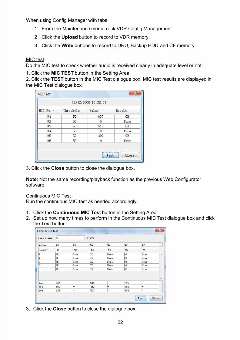
8102019 Ome44376d Vr3000 Mainte Cof26amp3bmol
httpslidepdfcomreaderfullome44376d-vr3000-mainte-cof26amp3bmol 2457
22
When using Config Manager with tabs
1 From the Maintenance menu click VDR Config Management
2 Click the Upload button to record to VDR memory
3 Click the Write buttons to record to DRU Backup HDD and CF memory
MIC testDo the MIC test to check whether audio is received clearly in adequate level or not
1 Click the MIC TEST button in the Setting Area
2 Click the TEST button in the MIC Test dialogue box MIC test results are displayed in
the MIC Test dialogue box
3 Click the Close button to close the dialogue box
Note Not the same recordingplayback function as the previous Web Configuratorsoftware
Continuous MIC TestRun the continuous MIC test as needed accordingly
1 Click the Continuous MIC Test button in the Setting Area2 Set up how many times to perform in the Continuous MIC Test dialogue box and click
the Test button
3 Click the Close button to close the dialogue box
8102019 Ome44376d Vr3000 Mainte Cof26amp3bmol
httpslidepdfcomreaderfullome44376d-vr3000-mainte-cof26amp3bmol 2557
23
Active Put check in check box to make channel activeBrand Enter and display brand nameType No Set type no (equipment name)Check Do equipment checkData Name Enter data nameInput Type Enter input type Sampling Data Bit Displays sampling data bit rate
Sampling Frequency Displays Sampling FrequencyCodec Sets MIC typeMIC Test Active M1M3M5 Put a checkmark when performing MIC Test of M1M3M5MIS Test Active M2M4M6 Put a checkmark when performing MIC Test of M2M4M6 MIC M1M3M5 Position Enter MIC position of MIC M1M3M5MIC M2M4M6 Position Enter MIC position of MIC M2M4M6Threshold Level M1M3M5 Enter MIC test threshold level of MIC M1M3M5Threshold Level M2M4M6 Enter MIC test threshold level of MIC M2M4M6Equipment Category Set equipment categoryBoard Name Enter board names where channels are present
Note Enter note Marked Items For easy identification of input source enter Equipment Category BrandType No Date and Name
8102019 Ome44376d Vr3000 Mainte Cof26amp3bmol
httpslidepdfcomreaderfullome44376d-vr3000-mainte-cof26amp3bmol 2657
24
27 Alarm
Alarm and Alarm Status settings are found in the Alarm tab
The Alarm tab shows the following information about alarms Click the Time Categoryand Name tabs in the title bar to sort
Time Time of alarm
Category Alarm categoryName Name of alarm
Number Alarm number
Status Alarm status
Alarm Search
1 Click the Search button above the Alarm tab The Search dialogue box appears
2 Add a checkmark to any desired search items (multiple items can be selected)
Start Time Display name of alarms generated after a certain time
End Time Display name of alarms generated before a certain time
Name Display information for alarm name entered
8102019 Ome44376d Vr3000 Mainte Cof26amp3bmol
httpslidepdfcomreaderfullome44376d-vr3000-mainte-cof26amp3bmol 2757
25
Number Display information for alarm number entered
Status Display alarm status for alarm name entered
3 In the checked items column input the desired search items
4 Click the Search Button
Close the Search box to cancel a search
Note During a search the upper left Mode changes from Play to Search andDisplay search related information
8102019 Ome44376d Vr3000 Mainte Cof26amp3bmol
httpslidepdfcomreaderfullome44376d-vr3000-mainte-cof26amp3bmol 2857
26
28 Event
Click the items shown below to sort by item selected
Note You can sort the items in ascending order () descending order () and
initialization order (no symbol)
Time Time an event occurred
Category Category of an event
Name Name of an event
Contents1 Display data associated with log
Contents2 Display data associated with log
Event Search
Do the following to search events
1 Click the Search button on the upper right of the Event tab
2 In the dialogue box add a checkmark to desired search items Multiple items can bechecked
Start Time Display name of event generated after a certain time
End Time Display name of event generated before a certain time
Name Display event names entered
Number Display event numbers entered
Status Display event status entered
Enter information about the checked event to search in the character input box
3 Click the Search button
Note The mode changes from Play to Search when performing a search
8102019 Ome44376d Vr3000 Mainte Cof26amp3bmol
httpslidepdfcomreaderfullome44376d-vr3000-mainte-cof26amp3bmol 2957
27
29 Hardware
The Hardware tab provides information about the system hardware
The buttons in the Setting window work as follows
Self Check Status Display status of self check
CPU Display information about the CPU
Memory Size Display memory size
CPU Board Display status of CPU board
Audio Board Display status of Audio board
Serial Board Display status of Serial board
Radar Interface Board Display status of Radar Interface boardNote Enter and display note
Marked items are optional
8102019 Ome44376d Vr3000 Mainte Cof26amp3bmol
httpslidepdfcomreaderfullome44376d-vr3000-mainte-cof26amp3bmol 3057
28
210 JB
Connect the Junction Box to the DCU before turning on the system
The JB tab functions to set up the Junction Box
The basic procedure for setting up the Junction Box is as follows
1 Click the JB tab2 Select a Junction Box from the Information Area
3 Set up the Junction Box from the Setting Area
4 Click the Set button (Be sure to do this before moving to another channel)5 Click the Check button to perform an inspection on all channels In the Information
Area check column either OK or NG (No Good) is displayed
When using Config Manager with Tabs
1 From the Maintenance menu click VDR Config Management
2 Click the Upload button to record to VDR memory
3 Click the Write buttons to record to DRU Backup HDD and CF
The items in the Setting window work as followsActive Put check in check box to make channel activeNo Display Junction Box numberIP Address Display IP address of Junction Box acquired by VDRMAC Address Display MAC address of Junction Box acquired by VDRCheck Enable and disable equipment checkNote Enter note
Marked items are optional
8102019 Ome44376d Vr3000 Mainte Cof26amp3bmol
httpslidepdfcomreaderfullome44376d-vr3000-mainte-cof26amp3bmol 3157
29
211 Life Time
The Life Time tab controls consumable parts
The basic procedure for using the Life Time tab is as follows
1 Click the Life Time tab
2 Select a Type No in the Information Area3 Set up the chosen part from Setting Area
4 Click the Set button
Note Be sure to click the Set button before moving to set up a different Type
The items in the Setting window work as follows
Type No Enter and display type no
Data Name Enter and display data name
Level Set replacement level Legal Exchange Parts or Normal Exchange Parts
Replace Date Enter and display recommended day of replacement
Lifetime Term Not usedNote Enter and display note
The Status column of the Information Area displays as follows
OK The recommended date of replacement shown in the Replace Date
box in the Information window has not passed
Out of Date The date of replacement has passed
None The date of replacement has not been set
8102019 Ome44376d Vr3000 Mainte Cof26amp3bmol
httpslidepdfcomreaderfullome44376d-vr3000-mainte-cof26amp3bmol 3257
30
212 Network
The Network tab sets the system network
The basic procedure for setting up the system network is as follows
1 Click the Network tab
2 Select a port from the Information Area
3 Set up the network from the Setting Area
4 Click the Set button
Note1 Be sure to click the Set button before moving to set up a different Port
Note2 After setting the system network reboot the VDR to apply the settings
The items in the Setting window work as follows
LAN Type Enter LAN type Public LAN or JB LAN
MAC Address Enter MAC address
IP Address Enter IP address
Subnet Mask Enter subnet mask
Gateway Address Enter gateway address
Live Play Multicast Mode (Only JB LAN) Check box to enable live player multicast
mode
Multicast Address (Only Public LAN) Enter and display live player multicast addressNote Enter note
Marked items are optional
8102019 Ome44376d Vr3000 Mainte Cof26amp3bmol
httpslidepdfcomreaderfullome44376d-vr3000-mainte-cof26amp3bmol 3357
31
213 System
The System tab sets system related functions
The basic procedure for using the System tab is as follows
1 Click the System tab
2 Set up the chosen item from the Setting Area
3 Click the Set button
Note Be sure to click the Set button before moving to a different tab
The items in the Setting window work as follows
VDR Type Enter type of VDR
VDR Model Enter model number of VDR
Radar Interface Check Enable and disable checking of the Radar Interface board
Junction Box Count Enter number of junction boxes in system
DRU Flash Count Enter number of DRU flash disks in system Set 1 when DRU
serial no is 5000 and more Set 3 when DRU serial no is less
than 5000
DRU Capacity Display capacity of DRU
Backup HDD Capacity Display capacity of Backup HDD
VDR Config Version Display version no of VDR
VDR Config Date Display the number of hours the VDR settings have
been saved
VDR Config Code Display configuration identity code
Installation Engineer Enter name of the equipment installer
Installation Company Enter name of installers company
8102019 Ome44376d Vr3000 Mainte Cof26amp3bmol
httpslidepdfcomreaderfullome44376d-vr3000-mainte-cof26amp3bmol 3457
32
Installation Date Enter the date of the installation
MIC Test Time Enter the date of the MIC test
Note Enter note Marked items are optional
USB memory logging Do not check Enable
IEEE1394 BUS Error Auto Restart function Not used
IEEE1394 Active Node Count Do not change the default value of 3 (However set to 5
for serial number 5000 or less of DRU)
IEEE1394 Recover Process Limit Count Do not change the default value of 10
DRU Error Auto Restart function Not used
REBOOT DELAY TIME (sec) Do not change the default value of 10
LIMIT REBOOT COUNT Do not change the default value of 10
Live Player Max Connection Count The max number of Live Player V4 that can be
connected simultaneously The default no is two
but a maximum of five can be set here After you
change this option reboot the VDR to apply the
setting Disconnect the cable connected with
Live Player V4 (PC) from the VDR and thenreconnect it
214 Software
The Software tab sets and display software-related operations
The basic procedure for using the Software tab is as follows
1 Click the Software tab
2 Set up the chosen Item from the Setting Area
3 Click the Set button
8102019 Ome44376d Vr3000 Mainte Cof26amp3bmol
httpslidepdfcomreaderfullome44376d-vr3000-mainte-cof26amp3bmol 3557
33
The items in the Setting window work as follows
VDR System Program Display the VDR system program no
Process Version Display the process version
Power Distribution Unit (PDU) Display the version no of the PDU
Operation System Display the version no of the OS
Audio Driver Display the version no of the audio driverRAP Version Enter the version no of the RAP
AP Version Enter the version no of the AP
JB1-8 Boot Program Display the no of the RJB Boot program for Junction Boxes
1 to 8
JB1-8 App Program Display the no of the RJB App program for Junction Boxes
1 to 8
Watch Dog Interval Do not change the default value of 60 (Enter the process
response time A process is repeated if there is no response
within the time interval set here)
Giveup Interval Do not change the default value of 300 (Enter the restart
watch time The restarting of a process is stopped when the
number of times it has been restarted is exceeded within the
interval set here)
Refork Limit Do not change the default value of 10 (Enter the upper limit
for process restart The restarting of a process is stopped
when the number of times it has been restarted exceeds the
Give up Interval)
Note Enter note
Marked Items are optional
8102019 Ome44376d Vr3000 Mainte Cof26amp3bmol
httpslidepdfcomreaderfullome44376d-vr3000-mainte-cof26amp3bmol 3657
34
215 GPS
The GPS tab sets GPS-related parameters
The basic procedure for using the GPS tab is as follows
1 Click the GPS tab
2 Set up the chosen channel from the Information window3 Set up the chosen item in the Setting Area
4 Click the Set button
5 Repeat steps 2-4 to set up each Channel
6 Click the Check button to perform an inspection on all channels In the Information Area check column either OK or NG (No Good) is displayed
The items in the Setting window work as follows
Priority Display priority order
Date and Time SourceShip Position Source Set GPS source channel (serial channel
number for ZDA sentence)
Check Enable and disable checking
GPS Antenna Position From Bow Enter position of GPS antenna from bow
GPS Antenna Position From Stern Enter position of GPS antenna from stern
GPS Antenna Position From Port Enter position of GPS antenna from port
GPS Antenna Position From Starboard Enter position of GPS antenna from starboard
GPS Failure Threshold If the ZDA is input within the set time limit
the system restarts synchronized If not
input within the time limit the system restarts
without synchronization
8102019 Ome44376d Vr3000 Mainte Cof26amp3bmol
httpslidepdfcomreaderfullome44376d-vr3000-mainte-cof26amp3bmol 3757
35
GPS Delay Time by Time Sync Enter minimum time delay for time
synchronization Time synchronization is started
only in the time set here
GPS Difference Interval The time set here is added to the GPS time to
synchronize the system time Leave at the default
0 value setting
GPS Sync Giveup Time If the system receives the GPS time within the
time set the system synchronizes with the time
When not receiving a signal the system displays
an ldquoerror 26rdquo message
ZDA Timeout Enter value (seconds) for ZDA timeout (234 error)
from GPS
Note Enter and display note
Marked Items are optional
216 VesselThe Vessel tab sets and displays own ships information such as name and IMO number
The basic procedure for using the Vessel tab is as follows
1 Click the Vessel tab
2 Set up information in the Setting window
3 Click the Set button (Be sure to do this before moving to another port)
4 From the Maintenance menu click VDR Config Management and then Config5 Click the Write buttons to save data to the DRU backup HDD CF
The buttons in the Setting window works as follows
Vessel Name Enter name of vessel
Vessel IMO Number Enter IMO number of vessel
Vessel Flag Enter flag of vessel
Approval of Authority Enter name of approving authority
Note Enter note
Marked items are optional
8102019 Ome44376d Vr3000 Mainte Cof26amp3bmol
httpslidepdfcomreaderfullome44376d-vr3000-mainte-cof26amp3bmol 3857
36
217 Delivery
The Delivery tab functions to transmit data from the VDR to a PC via Ethernet LAN Do
not use this function during live connection
The basic procedure for using the Delivery tab is as follows
1 Click the Delivery tab
2 Click the Add button to show the Delivery Config window
3 Select protocol from the Protocol drop-down box (Unicast or Multicast)
4 Enter IP address in the IP address input box
5 Enter port number in the port number input box
6 Click the tab of the data to send (Analog Digital or Serial)
7 Select the channel of the data to send
8 If Serial was selected at step 6 select applicable data sentence from the Inactivewindow Click the right arrow to move the data sentence to the Active window
9 Click the OK button to close the Delivery Config window
10 The settings are listed in a table in the Delivery window Check the checkbox in the
Active column and then click the Set button
The buttons in the Setting window works as follows
Set Save edited settings
Add Create new delivery settings
Modify Modify selected delivery settings
Delete Delete selected delivery settings
8102019 Ome44376d Vr3000 Mainte Cof26amp3bmol
httpslidepdfcomreaderfullome44376d-vr3000-mainte-cof26amp3bmol 3957
37
3 How to Back up Configuration DataThis chapter shows how to back up configuration data to various storage media
Configuration data can be opened with Word Pad or any text editor other than Notepad
31 How to Back up Configuration Data to the Startup CompactFlash (CF)
Back up data to the startup CF after setting the VDR Configuration data is created on the
CF as a configini file
Note When the error shown below occurs during the downloading or uploading of
configuration data check the connection of the DRU Backup HDD and CF and then
upload or download the configuration data again
[CONN] Download failed
[CONN] Could not upload config file
If error occurs again re-install the VDR Maintenance Viewer
Do the following to back up data to a CF
1 Set up parameters on the tabs referring to Chapter 2
2 Click the Maintenance menu
3 Select VDR Config Management
4 Click the Upload button
5 A confirmation box appears click the OK button to start uploading to the VDR
6 Click the Write button where the arrow connects between VDR and DRU BackupHDD
7 A confirmation window appears click the OK button to save the configuration data tothe DRU and Backup HDD
8102019 Ome44376d Vr3000 Mainte Cof26amp3bmol
httpslidepdfcomreaderfullome44376d-vr3000-mainte-cof26amp3bmol 4057
38
8 Click the Write button where the arrow connects between the VDR and CF
9 A confirmation window appears click the OK button to save the configuration data tothe startup CF
10 Check that the PC VDR DRU Backup HDD and CF share the same VDR configcode
32 How to Back up Configuration Data to a PC
Configuration data saved to the PC can be edited with Wordpad and shared with other
vessels For future service ease it is recommended to backup configuration data to the
PC and have the data on board the vessel Also it is recommended to upload this data to
Furuno SMS (Service Management System) If unable to upload to Furuno SMS please
contact the Service Center Furuno Japan
To back up configuration data to the PC do as follows
1 Set up parameters on the tabs referring to Chapter 2
2 Click the Maintenance menu
3 Select VDR Config Management
4 Click the Export to button
5 A confirmation window appears click the OK button
6 Select where to save the data enter file name then click the Open button
7 Confirm that back up file is in the location selected
33 How to restore the default settings
Click the Default button on the VDR Config Management window to restore the default
settings of the DRU Backup HDD CF and VDR Maintenance Viewer
8102019 Ome44376d Vr3000 Mainte Cof26amp3bmol
httpslidepdfcomreaderfullome44376d-vr3000-mainte-cof26amp3bmol 4157
39
4 How to Upload Configuration Datafrom a PCThe procedure below shows how to upload configuration from the PC to aVR-3000VR-3000S
1 Click the Maintenance menu
2 Select VDR Config Management
3 Click the Import from button
4 The Open window appears Select configuration data and then click the Open button
5 Click the Upload button to upload data to the VR-3000VR-3000S
6 Click the Write buttons to save data to the DRU backup HDD and CF
8102019 Ome44376d Vr3000 Mainte Cof26amp3bmol
httpslidepdfcomreaderfullome44376d-vr3000-mainte-cof26amp3bmol 4257
40
5 Media ManagementThe media management feature deletes data from recording media initialization the
system etc There are two method LAN connection and Direct connection The Direct
connection takes longer time than the LAN connection Basically use the LAN connection
method
Note Initialization or creation of recording media is not available when Source Select onthe Live Player V4 is selected to Backup HDD
51 Initialization
This section shows how to delete data from the recording media Configuration data is
not deleted After performing the software configuration delete the data from the DRU
and HDD
Do the following to delete data from the DRU (LAN connection)
1 Set the PlaybackCPU switch in the DCU to the CPU position
2 Use an Ethernet cross cable to connect the PC to J14 (DATA) in the DCU (See page5)
3 Open the Tool menu
4 Select Media Management to open the VDR Media Management window
5 Check that IP address shown in the ldquoLAN Connect to IPrdquo in VDR Media Table Area isthe same as the IP address access point
6 Select ldquoLAN Connect to IPrdquo in the VDR Media Table column
8102019 Ome44376d Vr3000 Mainte Cof26amp3bmol
httpslidepdfcomreaderfullome44376d-vr3000-mainte-cof26amp3bmol 4357
41
7 Click the Analyze button A list of recording media connected to the VDR appears
Put a checkmark in the checkbox of the Select column for the DRU in the Name columnNote If there are several flash memories in the DRU all flash memories are shownCheck all flash memories shown
8 Select ldquoDRU Initializerdquo from the Operation dropdown list in the Operation area
10 Click the Run button
Do the following to delete data from the DRU (Direct connection)
1 Start Live Player V4 software
2 Open the Tool menu and select Source Select Select Live from the pull-downmenu
3 Click the Alarm tab and open Alarm History
4 Set the PlaybackCPU switch in the DCU to the Playback position
5 Wait approx 10 minutes and confirm that Alarm 174 occurs on Alarm History of LivePlayer V4
6 Connect an IEEEE1394 cable between J6 in the DCU and the PC
7 Open the Tool menu
8 Select Media Management to show the VDR Media Management window
9 Select Direct in the VDR Media Table column
10 Click the Analyze button A list of recording media connected to the VDR appears
11 Put a checkmark in the checkbox of the Select column for the DRU in the Namecolumn
Note If there are several flash memories in the DRU all flash memories are shownCheck all flash memories shown
12 Select ldquoDRU Initializerdquo from the Operation dropdown list in the Operation area
13 Enter password in the password column
14 Click the RUN button
8102019 Ome44376d Vr3000 Mainte Cof26amp3bmol
httpslidepdfcomreaderfullome44376d-vr3000-mainte-cof26amp3bmol 4457
42
Delete data from the Backup HDD as follows (LAN connection)
1 Set the PlaybackCPU switch in the DCU to the CPU position
2 Check that an Ethernet cross cable is connected between J14 in the DCU and the PC
3 Open the Tool menu
4 Select Media Management to open the VDR Media Management window
5 Check that IP address shown in the LAN Connect to IP in VDR Media Table Area is
the same as the IP address access point6 Select LAN Connect to IP in the VDR Media Table column
7 Click the Analyze button
8 A list of recording media connected to the VDR appears
9 Put a checkmark in the box of the Select column for the Backup HDD in the Namecolumn Select ldquoBackup HDD Initializerdquo from the Operation dropdown list in theOperation area
10 Click the Run button
Delete data from the Backup HDD as follows (Direct connection)
1 Start Live Player V4 software
2 Open the Tool menu and select Source Select Select Live from the pull-downmenu
3 Click the Alarm tab and open Alarm History
4 Set the PlaybackCPU switch in the DCU to the Playback position
5 Wait approx 10 minutes and confirm that Alarm 174 occurs on Alarm History of LivePlayer V4
6 Connect an IEEE1394 cable between J6 in the DCU and the PC
7 Open the Tool menu
8 Select Media Management to open the VDR Media Management window9 Select Direct in the VDR Media Table window
10 Click the Analyze button A list of recording media connected to the VDR appears
11 Put a checkmark in the check box of the Select column for the Backup HDD in theName column Select ldquoBackup HDD Initializerdquo from the Operation dropdown list in theOperation area
12 Enter password
13 Click the Run button
8102019 Ome44376d Vr3000 Mainte Cof26amp3bmol
httpslidepdfcomreaderfullome44376d-vr3000-mainte-cof26amp3bmol 4557
43
52 CreationThe Creation feature initializes recording media
Note1 This feature deletes ALL configuration data Backup all VDR configuration data
Note2 When you initialize medium that is a different format for the DRU or Backup HDDdelete all partitions with the disk management tool of Windows
Note3 When the Creation is failed try again If you can not initialize recording media tryunder condition as shown below
Do the Creation by the direct connection (When the Creation by the LAN
connection is failed)
Delete all partitions of the DRU or Backup HDD with the disk management tool of
Windows to do the Creation
If the Creation is still failed request service to repairreplace the DRU or Backup
HDD
Initialize the DRU as follows (LAN connection)
1 Set the PlaybackCPU switch in the DCU to the CPU position
2 Check that an Ethernet cross cable is connected between J14 in the DCU and the PC
3 Open the Tool menu
4 Select Media Management to open the VDR Media Management window
5 Check that IP address shown in the LAN Connect to IP in VDR Media Table Area isthe same as the IP address access point
6 Check ldquoLAN Connect to IPrdquo in the VDR Media Table column
7 Click the Analyze button A list of recording media connected to the VDR appears
8 Put a checkmark in the box of the Select column for the DRU in the Name column
Select ldquoDRU Creationrdquo from the Operation dropdown list in the Operation area
9 Click the Run button
Initialize the Backup HDD as follows (LAN connection)
1 To format the Backup HDD place a checkmark in the Select column of the listedrecord media in the Name column of the VDR Media Management dialogue box
2 From the Operation drop down list of the Operation area select ldquoBackup HDDCreation (Radar) or ldquoBackup HDD Creationrdquo
Two partition tools are available for the Backup HDD in the Media Management as
below
Backup HDD creation
This tool is used when the number of the SXGA video signal connected to the BackupHDD is the same as the DRU The same partition is created on both DRU and HDD
(1) When two SXGA video signals are recorded onto the HDD while 9-GB DRU isconnected
(2) When an SXGA video signal is recorded onto the HDD while 6-GB DRU isconnected
Backup HDD creation (radar)
This tool is used when two SXGA video signals are recorded onto the HDD with 6-GB
DRU connected The HDD has an area (radar) to record the second radar signal inaddition to the same partition as the DRU This tool cannot be used when 9-GB DRUis connected
3 Press the Run Button
8102019 Ome44376d Vr3000 Mainte Cof26amp3bmol
httpslidepdfcomreaderfullome44376d-vr3000-mainte-cof26amp3bmol 4657
44
Initialize the DRU as follows (Direct connection)
1 Start Live Player V4 software
2 Open the Tool menu and select Source Select Select Live from the pull-downmenu
3 Click the Alarm tab and open Alarm History
4 Set the PlaybackCPU switch in the DCU to the Playback position
5 Wait approx 10 minutes and confirm that Alarm 174 occurs on Alarm History of LivePlayer V4
6 Connect an IEEE1394 cable between J6 in the DCU and the PC
7 Open the Tool menu
8 Select Media Management to open the VDR Media Management window
9 Select Direct in the VDR Media Table window
10 Click the Analyze button A list of recording media connected to the VDR appears
11 Put a checkmark in the box of the Select column for the DRU and the desiredrecording media in the Name column In the Operation dropdown list of the Operationarea select ldquoDRU Creationrdquo
12 Enter password in the password column
13 Click the Run button
Initialize the Backup HDD as follows (Direct Connection)
1 To format the Backup HDD place a checkmark in the Select column of the listedrecord media in the Name column of the VDR Media Management dialogue box
2 From the Operation column of the Operation area select ldquoBackup HDD Creation(Radar) or ldquoBackup HDD Creationrdquo
Backup HDD creation
This tool is used when the number of the SXGA video signal connected to the BackupHDD is the same as the DRU The same partition is created on both DRU and HDD
(1) When two SXGA video signals are recorded onto the HDD while 9-GB DRU is
connected
(2) When an SXGA video signal is recorded onto the HDD while 6-GB DRU is
connected
Backup HDD creation (radar)
This tool is used when two SXGA video signals are recorded onto the HDD with 6-GBDRU connected The HDD has an area (radar) to record the second radar signal inaddition to the same partition as the DRU This tool cannot be used when 9-GB DRUis connected
3 Enter the password in the Password column
4 Press the Run Button
8102019 Ome44376d Vr3000 Mainte Cof26amp3bmol
httpslidepdfcomreaderfullome44376d-vr3000-mainte-cof26amp3bmol 4757
45
53 How to Enable Recording Area on the Backup HDD
This function enables writing over a recording area To prevent falsification of data all
recording areas must be saved otherwise this function is disabled To use this function push
the SAVE button Save the data before doing this procedure
Note Software version 135 or higher can enable writing over a recording area even if
all recording areas are not saved
Recording enable (LAN connection)
1 Set the PlaybackCPU switch in the DCU to the CPU position
2 Check that an Ethernet cross cable is connected between J14 in the DCU and the PC
3 Open the Tool menu
4 Select Media Management to open the VDR Media Management window
5 Check that IP address shown in the ldquoLAN Connect to IPrdquo in VDR Media Table Area isthe same as the IP address access point
6 Select ldquoLAN Connect to IPrdquo in the VDR Media Table column7 Click the Analyze button A list of recording media connected to the VDR appears
8 Put a checkmark in the box of the Select column for the Backup HDD in the Namecolumn
9 Select ldquoBackup HDD Recording Area Enablerdquo from the Operation dropdown list in theOperation area
10 Click the Run button
Recording enable (Direct connection)
1 Start Live Player V4 software
2 Open the Tool menu and select Source Select Select Live from the pull-down menu3 Click the Alarm tab and open Alarm History
4 Set the PlaybackCPU switch in the DCU to the Playback position
5 Wait approx 10 minutes and confirm that Alarm 174 occurs on Alarm History of LivePlayer V4
6 Connect an IEEE1394 cable between J6 in the DCU and the PC
7 Open the Tool menu
8 Select Media Management to open the VDR Media Management window
9 Select Direct in the VDR Media Table window
10 Click the Analyze button A list of recording media connected to the VDR appears11 Put a checkmark in the box of the Select column for the Backup HDD in the Name
column
12 Select ldquoBackup HDD Recording Area Enablerdquo from the Operation dropdown list in theOperation area
13 Enter password
14 Click the Run button
8102019 Ome44376d Vr3000 Mainte Cof26amp3bmol
httpslidepdfcomreaderfullome44376d-vr3000-mainte-cof26amp3bmol 4857
46
6 Other Functions
61 Software Management
The software download feature downloads VDR system software to the PC
To download software
1 Click the Maintenance menu
2 From the Software Management menu click Software Download to show theSoftware Download window
3 Enter the IP address 1000100 in the IP address box in the Update Server area
4 Click the Download Software button
5 The confirmation window appears click the OK button
The Software Backup Execute window shows the results of the download
Software is downloaded to C Program Files VDR Viewer Viewer Backup The software file
name is vdrtar
To Update Software
VDR system program version 16x can update the software with the procedure shownbelow
Note Do not update the file downloaded in procedures above
1 Click the Maintenance menu
2 From the Software Management menu click Software Upload to show the SoftwareUpload area
3 Click the Select button to show the Open window
4 Select update file (vdrtar) and click the Open button
8102019 Ome44376d Vr3000 Mainte Cof26amp3bmol
httpslidepdfcomreaderfullome44376d-vr3000-mainte-cof26amp3bmol 4957
47
5 Check the displayed Software information is correct
6 Enter the IP address 1000100 in the IP address box in the Update Server area
7 Enter password
8 Click the Update button
After the updating is completed the VDR is automatically restarted
Note Click the Restore button on the Software Update window to restore previoussoftware version This feature is available after updating the software
62 Password Management
The password can be changed for a serviceman to access the equipment Contact
FURUNO to get the default password to use during installation
Serviceman password
1 Click the Maintenance menu2 Select Change Serviceman Password from Password Management to show the
Change Serviceman Password window
3 Enter current password in the Old Password box
4 Enter the new password in the New Password box of the Change Password area
5 Enter new password again in the Confirm New Password box
6 Click the OK button
Audio password
The audio password set at the VDR Maintenance Viewer can be removed to enable
audio access without password1 Click the Maintenance menu
2 Select Change Audio Password from Password Management to show the Change Audio Password window
3 The confirmation window appears click the OK button
8102019 Ome44376d Vr3000 Mainte Cof26amp3bmol
httpslidepdfcomreaderfullome44376d-vr3000-mainte-cof26amp3bmol 5057
48
63 Record ComparisonThe integrity of the DRU and Backup HDD recordings can be compared This function isused by the RampD engineer for debugging
Follow the procedure as shown below
1 Click the Maintenance menu2 Select Record Comparison to show the Record Comparison window
The results are shown every 15 seconds in the Record Comparison window
8102019 Ome44376d Vr3000 Mainte Cof26amp3bmol
httpslidepdfcomreaderfullome44376d-vr3000-mainte-cof26amp3bmol 5157
49
64 Software History
This section shows you to save and configure software history (communications record)
How to save software history
Note When the error dialog appears while saving the software history restart the VDR
Maintenance Viewer
1 Click the Maintenance menu
2 Select Software History Collect
3 Click the Select button The Open dialog box appears
4 Select where to save the data then click the Open button
5 Select desired save condition then click the OK buttonNone No savingAt Once Save the software history manually Saving begins as soon as the OK button is clickedPeriodic For debugging Do not use otherwise The intervals are 30 sec 60 secand 120 secAlarm Detection For debugging Do not use otherwise Software history is savedwhen specified alarm is released Enter alarm number
How to configure software communications record
The RampD engineer uses this function for debugging Do not do this procedure unless
required Malfunction can result
1 Click the Maintenance menu
2 Select Software History Config
3 Do the followingProcess Select the type of communications record to save ALL saves allcommunications records
Detail Hide or show detailed information4 Click the Send button
8102019 Ome44376d Vr3000 Mainte Cof26amp3bmol
httpslidepdfcomreaderfullome44376d-vr3000-mainte-cof26amp3bmol 5257
50
65 Easy SetupThis feature sets equipment settings in batch and creates a data file of those settings
Default template The default template is created with the settings entered at installation
1 Click the Maintenance menu
2 Select Easy Setup to show the Template Selection window
3 Select Default Template
4 Click the Start button to show the Easy Setup window
5 Right click the channels (Radar Audio Digital Serial Analog) then select Edit toshow the Equipment Selection window
6 From the Equipment Directory window select equipment connected to the selectedchannel and then click the OK button
7 Repeat steps 5 and 6 to select equipment settings for each channel
8 Click the Save button in the Easy Setup window to show the Save window
9 Select where to save the file and enter file name
10 Click the Save button
8102019 Ome44376d Vr3000 Mainte Cof26amp3bmol
httpslidepdfcomreaderfullome44376d-vr3000-mainte-cof26amp3bmol 5357
51
Specific template Use a file already created
1 Click the Maintenance menu
2 Select Easy Setup to show the Template Selection window
3 Check Specified Template
4 Click the Select button and then select the file to edit
5 Click the Start button to show the Easy Setup window
6 Right click the channels (Radar Audio Digital Serial Analog) then select Edit toshow the Equipment Selection window
7 From the Equipment Directory window select equipment connected to the selectedchannel and then click the OK button
8 Repeat steps 6 and 7 to select equipment settings for each channel
9 Click the Save button in the Easy Setup window to show the Save window
10Select where to save the file and enter file name
11 Click the Save button
66 Equipment Management
This feature controls the import and export of equipment settings
Import data file
Import data files of equipment settings created in Easy Setup etc to the VDR
1 Click the Maintenance menu
2 Select Import from Equipment Management to show the Open window
3 Select the data file to import and click Open
Export data file
Export data files of equipment settings from the VDR to a PC
1 Click the Maintenance menu
2 Select Export from Equipment Management to show the Save window
3 Enter file name
4 Click the Save button
8102019 Ome44376d Vr3000 Mainte Cof26amp3bmol
httpslidepdfcomreaderfullome44376d-vr3000-mainte-cof26amp3bmol 5457
52
67 PC_RAP
This feature enables the same operation of the RAP (Remote Alarm Panel) from a PC
Select PC_RAP from the Tool menu to show the PC_RAP window
The buttons in the PC_RAP window function as shown below
SAVE Stop recording in the area where recording is currently being done
ACK Silence audio alarm
The PC_RAP display shows the following information with LEDs
RAP_LEDs Display the status of LEDs on the RAPSave The Save button blinks yellow when pushed When the 4 memory
areas have data recorded to them the Save button lights orange when
pushed
Normal Lights (green) where there are no unconfirmed or not restored
alarms
Error Flashes (red) for not confirmed alarm Lights (red) for unrestored
alarm
8102019 Ome44376d Vr3000 Mainte Cof26amp3bmol
httpslidepdfcomreaderfullome44376d-vr3000-mainte-cof26amp3bmol 5557
53
Backup HDD Information Display status of backup HDD
Selected Display current recording area and its status in green for
normal operation and in red for abnormal operation
Size Display capacity of backup HDD
Alarm area displays unconfirmed alarms
Time Display time alarm was generatedNumber Display number of alarm
Name Display name of alarm
Pending Alarm displays the unrestored alarms out of confirmed alarms only
Time Display time alarm was generated
Number Display number of alarm
Name Display name of alarm
8102019 Ome44376d Vr3000 Mainte Cof26amp3bmol
httpslidepdfcomreaderfullome44376d-vr3000-mainte-cof26amp3bmol 5657
54
68 Other
Status Monitor
The status monitor feature provides comprehensive data about the status of the VDR
From the menu bar click Toolgt Status Monitor to show the Status Monitor window
The buttons in the Status Monitor window work as shown below
Reload Settings for automatic refreshing of the status monitor
ON Turn automatic refresh OFF
OFF The Status Monitor is refreshed every five seconds
Save Available when Reload ON is selected The contents of the Status Monitor can be
saved to a text fileUpdate Update the Status Monitor display
Close Close the Status Monitor display
8102019 Ome44376d Vr3000 Mainte Cof26amp3bmol
httpslidepdfcomreaderfullome44376d-vr3000-mainte-cof26amp3bmol 5757
VDR Error List
This feature compiles all the errors shown on the RAP for easy reference
Access from MenugtToolgtVDR Error List
The VDR error list contains the following information
NO Display the number of the error
Title Display the name of the error
Detail Display details about the error
Exchange Check
This feature removes the alarms generated when replacing the DRU or backup HDD
Access MenugtToolgtExchange Check select either DRU or Backup HDD and click OK
Reboot
Reboot the VDR
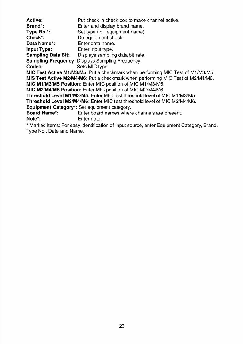
8102019 Ome44376d Vr3000 Mainte Cof26amp3bmol
httpslidepdfcomreaderfullome44376d-vr3000-mainte-cof26amp3bmol 2557
23
Active Put check in check box to make channel activeBrand Enter and display brand nameType No Set type no (equipment name)Check Do equipment checkData Name Enter data nameInput Type Enter input type Sampling Data Bit Displays sampling data bit rate
Sampling Frequency Displays Sampling FrequencyCodec Sets MIC typeMIC Test Active M1M3M5 Put a checkmark when performing MIC Test of M1M3M5MIS Test Active M2M4M6 Put a checkmark when performing MIC Test of M2M4M6 MIC M1M3M5 Position Enter MIC position of MIC M1M3M5MIC M2M4M6 Position Enter MIC position of MIC M2M4M6Threshold Level M1M3M5 Enter MIC test threshold level of MIC M1M3M5Threshold Level M2M4M6 Enter MIC test threshold level of MIC M2M4M6Equipment Category Set equipment categoryBoard Name Enter board names where channels are present
Note Enter note Marked Items For easy identification of input source enter Equipment Category BrandType No Date and Name
8102019 Ome44376d Vr3000 Mainte Cof26amp3bmol
httpslidepdfcomreaderfullome44376d-vr3000-mainte-cof26amp3bmol 2657
24
27 Alarm
Alarm and Alarm Status settings are found in the Alarm tab
The Alarm tab shows the following information about alarms Click the Time Categoryand Name tabs in the title bar to sort
Time Time of alarm
Category Alarm categoryName Name of alarm
Number Alarm number
Status Alarm status
Alarm Search
1 Click the Search button above the Alarm tab The Search dialogue box appears
2 Add a checkmark to any desired search items (multiple items can be selected)
Start Time Display name of alarms generated after a certain time
End Time Display name of alarms generated before a certain time
Name Display information for alarm name entered
8102019 Ome44376d Vr3000 Mainte Cof26amp3bmol
httpslidepdfcomreaderfullome44376d-vr3000-mainte-cof26amp3bmol 2757
25
Number Display information for alarm number entered
Status Display alarm status for alarm name entered
3 In the checked items column input the desired search items
4 Click the Search Button
Close the Search box to cancel a search
Note During a search the upper left Mode changes from Play to Search andDisplay search related information
8102019 Ome44376d Vr3000 Mainte Cof26amp3bmol
httpslidepdfcomreaderfullome44376d-vr3000-mainte-cof26amp3bmol 2857
26
28 Event
Click the items shown below to sort by item selected
Note You can sort the items in ascending order () descending order () and
initialization order (no symbol)
Time Time an event occurred
Category Category of an event
Name Name of an event
Contents1 Display data associated with log
Contents2 Display data associated with log
Event Search
Do the following to search events
1 Click the Search button on the upper right of the Event tab
2 In the dialogue box add a checkmark to desired search items Multiple items can bechecked
Start Time Display name of event generated after a certain time
End Time Display name of event generated before a certain time
Name Display event names entered
Number Display event numbers entered
Status Display event status entered
Enter information about the checked event to search in the character input box
3 Click the Search button
Note The mode changes from Play to Search when performing a search
8102019 Ome44376d Vr3000 Mainte Cof26amp3bmol
httpslidepdfcomreaderfullome44376d-vr3000-mainte-cof26amp3bmol 2957
27
29 Hardware
The Hardware tab provides information about the system hardware
The buttons in the Setting window work as follows
Self Check Status Display status of self check
CPU Display information about the CPU
Memory Size Display memory size
CPU Board Display status of CPU board
Audio Board Display status of Audio board
Serial Board Display status of Serial board
Radar Interface Board Display status of Radar Interface boardNote Enter and display note
Marked items are optional
8102019 Ome44376d Vr3000 Mainte Cof26amp3bmol
httpslidepdfcomreaderfullome44376d-vr3000-mainte-cof26amp3bmol 3057
28
210 JB
Connect the Junction Box to the DCU before turning on the system
The JB tab functions to set up the Junction Box
The basic procedure for setting up the Junction Box is as follows
1 Click the JB tab2 Select a Junction Box from the Information Area
3 Set up the Junction Box from the Setting Area
4 Click the Set button (Be sure to do this before moving to another channel)5 Click the Check button to perform an inspection on all channels In the Information
Area check column either OK or NG (No Good) is displayed
When using Config Manager with Tabs
1 From the Maintenance menu click VDR Config Management
2 Click the Upload button to record to VDR memory
3 Click the Write buttons to record to DRU Backup HDD and CF
The items in the Setting window work as followsActive Put check in check box to make channel activeNo Display Junction Box numberIP Address Display IP address of Junction Box acquired by VDRMAC Address Display MAC address of Junction Box acquired by VDRCheck Enable and disable equipment checkNote Enter note
Marked items are optional
8102019 Ome44376d Vr3000 Mainte Cof26amp3bmol
httpslidepdfcomreaderfullome44376d-vr3000-mainte-cof26amp3bmol 3157
29
211 Life Time
The Life Time tab controls consumable parts
The basic procedure for using the Life Time tab is as follows
1 Click the Life Time tab
2 Select a Type No in the Information Area3 Set up the chosen part from Setting Area
4 Click the Set button
Note Be sure to click the Set button before moving to set up a different Type
The items in the Setting window work as follows
Type No Enter and display type no
Data Name Enter and display data name
Level Set replacement level Legal Exchange Parts or Normal Exchange Parts
Replace Date Enter and display recommended day of replacement
Lifetime Term Not usedNote Enter and display note
The Status column of the Information Area displays as follows
OK The recommended date of replacement shown in the Replace Date
box in the Information window has not passed
Out of Date The date of replacement has passed
None The date of replacement has not been set
8102019 Ome44376d Vr3000 Mainte Cof26amp3bmol
httpslidepdfcomreaderfullome44376d-vr3000-mainte-cof26amp3bmol 3257
30
212 Network
The Network tab sets the system network
The basic procedure for setting up the system network is as follows
1 Click the Network tab
2 Select a port from the Information Area
3 Set up the network from the Setting Area
4 Click the Set button
Note1 Be sure to click the Set button before moving to set up a different Port
Note2 After setting the system network reboot the VDR to apply the settings
The items in the Setting window work as follows
LAN Type Enter LAN type Public LAN or JB LAN
MAC Address Enter MAC address
IP Address Enter IP address
Subnet Mask Enter subnet mask
Gateway Address Enter gateway address
Live Play Multicast Mode (Only JB LAN) Check box to enable live player multicast
mode
Multicast Address (Only Public LAN) Enter and display live player multicast addressNote Enter note
Marked items are optional
8102019 Ome44376d Vr3000 Mainte Cof26amp3bmol
httpslidepdfcomreaderfullome44376d-vr3000-mainte-cof26amp3bmol 3357
31
213 System
The System tab sets system related functions
The basic procedure for using the System tab is as follows
1 Click the System tab
2 Set up the chosen item from the Setting Area
3 Click the Set button
Note Be sure to click the Set button before moving to a different tab
The items in the Setting window work as follows
VDR Type Enter type of VDR
VDR Model Enter model number of VDR
Radar Interface Check Enable and disable checking of the Radar Interface board
Junction Box Count Enter number of junction boxes in system
DRU Flash Count Enter number of DRU flash disks in system Set 1 when DRU
serial no is 5000 and more Set 3 when DRU serial no is less
than 5000
DRU Capacity Display capacity of DRU
Backup HDD Capacity Display capacity of Backup HDD
VDR Config Version Display version no of VDR
VDR Config Date Display the number of hours the VDR settings have
been saved
VDR Config Code Display configuration identity code
Installation Engineer Enter name of the equipment installer
Installation Company Enter name of installers company
8102019 Ome44376d Vr3000 Mainte Cof26amp3bmol
httpslidepdfcomreaderfullome44376d-vr3000-mainte-cof26amp3bmol 3457
32
Installation Date Enter the date of the installation
MIC Test Time Enter the date of the MIC test
Note Enter note Marked items are optional
USB memory logging Do not check Enable
IEEE1394 BUS Error Auto Restart function Not used
IEEE1394 Active Node Count Do not change the default value of 3 (However set to 5
for serial number 5000 or less of DRU)
IEEE1394 Recover Process Limit Count Do not change the default value of 10
DRU Error Auto Restart function Not used
REBOOT DELAY TIME (sec) Do not change the default value of 10
LIMIT REBOOT COUNT Do not change the default value of 10
Live Player Max Connection Count The max number of Live Player V4 that can be
connected simultaneously The default no is two
but a maximum of five can be set here After you
change this option reboot the VDR to apply the
setting Disconnect the cable connected with
Live Player V4 (PC) from the VDR and thenreconnect it
214 Software
The Software tab sets and display software-related operations
The basic procedure for using the Software tab is as follows
1 Click the Software tab
2 Set up the chosen Item from the Setting Area
3 Click the Set button
8102019 Ome44376d Vr3000 Mainte Cof26amp3bmol
httpslidepdfcomreaderfullome44376d-vr3000-mainte-cof26amp3bmol 3557
33
The items in the Setting window work as follows
VDR System Program Display the VDR system program no
Process Version Display the process version
Power Distribution Unit (PDU) Display the version no of the PDU
Operation System Display the version no of the OS
Audio Driver Display the version no of the audio driverRAP Version Enter the version no of the RAP
AP Version Enter the version no of the AP
JB1-8 Boot Program Display the no of the RJB Boot program for Junction Boxes
1 to 8
JB1-8 App Program Display the no of the RJB App program for Junction Boxes
1 to 8
Watch Dog Interval Do not change the default value of 60 (Enter the process
response time A process is repeated if there is no response
within the time interval set here)
Giveup Interval Do not change the default value of 300 (Enter the restart
watch time The restarting of a process is stopped when the
number of times it has been restarted is exceeded within the
interval set here)
Refork Limit Do not change the default value of 10 (Enter the upper limit
for process restart The restarting of a process is stopped
when the number of times it has been restarted exceeds the
Give up Interval)
Note Enter note
Marked Items are optional
8102019 Ome44376d Vr3000 Mainte Cof26amp3bmol
httpslidepdfcomreaderfullome44376d-vr3000-mainte-cof26amp3bmol 3657
34
215 GPS
The GPS tab sets GPS-related parameters
The basic procedure for using the GPS tab is as follows
1 Click the GPS tab
2 Set up the chosen channel from the Information window3 Set up the chosen item in the Setting Area
4 Click the Set button
5 Repeat steps 2-4 to set up each Channel
6 Click the Check button to perform an inspection on all channels In the Information Area check column either OK or NG (No Good) is displayed
The items in the Setting window work as follows
Priority Display priority order
Date and Time SourceShip Position Source Set GPS source channel (serial channel
number for ZDA sentence)
Check Enable and disable checking
GPS Antenna Position From Bow Enter position of GPS antenna from bow
GPS Antenna Position From Stern Enter position of GPS antenna from stern
GPS Antenna Position From Port Enter position of GPS antenna from port
GPS Antenna Position From Starboard Enter position of GPS antenna from starboard
GPS Failure Threshold If the ZDA is input within the set time limit
the system restarts synchronized If not
input within the time limit the system restarts
without synchronization
8102019 Ome44376d Vr3000 Mainte Cof26amp3bmol
httpslidepdfcomreaderfullome44376d-vr3000-mainte-cof26amp3bmol 3757
35
GPS Delay Time by Time Sync Enter minimum time delay for time
synchronization Time synchronization is started
only in the time set here
GPS Difference Interval The time set here is added to the GPS time to
synchronize the system time Leave at the default
0 value setting
GPS Sync Giveup Time If the system receives the GPS time within the
time set the system synchronizes with the time
When not receiving a signal the system displays
an ldquoerror 26rdquo message
ZDA Timeout Enter value (seconds) for ZDA timeout (234 error)
from GPS
Note Enter and display note
Marked Items are optional
216 VesselThe Vessel tab sets and displays own ships information such as name and IMO number
The basic procedure for using the Vessel tab is as follows
1 Click the Vessel tab
2 Set up information in the Setting window
3 Click the Set button (Be sure to do this before moving to another port)
4 From the Maintenance menu click VDR Config Management and then Config5 Click the Write buttons to save data to the DRU backup HDD CF
The buttons in the Setting window works as follows
Vessel Name Enter name of vessel
Vessel IMO Number Enter IMO number of vessel
Vessel Flag Enter flag of vessel
Approval of Authority Enter name of approving authority
Note Enter note
Marked items are optional
8102019 Ome44376d Vr3000 Mainte Cof26amp3bmol
httpslidepdfcomreaderfullome44376d-vr3000-mainte-cof26amp3bmol 3857
36
217 Delivery
The Delivery tab functions to transmit data from the VDR to a PC via Ethernet LAN Do
not use this function during live connection
The basic procedure for using the Delivery tab is as follows
1 Click the Delivery tab
2 Click the Add button to show the Delivery Config window
3 Select protocol from the Protocol drop-down box (Unicast or Multicast)
4 Enter IP address in the IP address input box
5 Enter port number in the port number input box
6 Click the tab of the data to send (Analog Digital or Serial)
7 Select the channel of the data to send
8 If Serial was selected at step 6 select applicable data sentence from the Inactivewindow Click the right arrow to move the data sentence to the Active window
9 Click the OK button to close the Delivery Config window
10 The settings are listed in a table in the Delivery window Check the checkbox in the
Active column and then click the Set button
The buttons in the Setting window works as follows
Set Save edited settings
Add Create new delivery settings
Modify Modify selected delivery settings
Delete Delete selected delivery settings
8102019 Ome44376d Vr3000 Mainte Cof26amp3bmol
httpslidepdfcomreaderfullome44376d-vr3000-mainte-cof26amp3bmol 3957
37
3 How to Back up Configuration DataThis chapter shows how to back up configuration data to various storage media
Configuration data can be opened with Word Pad or any text editor other than Notepad
31 How to Back up Configuration Data to the Startup CompactFlash (CF)
Back up data to the startup CF after setting the VDR Configuration data is created on the
CF as a configini file
Note When the error shown below occurs during the downloading or uploading of
configuration data check the connection of the DRU Backup HDD and CF and then
upload or download the configuration data again
[CONN] Download failed
[CONN] Could not upload config file
If error occurs again re-install the VDR Maintenance Viewer
Do the following to back up data to a CF
1 Set up parameters on the tabs referring to Chapter 2
2 Click the Maintenance menu
3 Select VDR Config Management
4 Click the Upload button
5 A confirmation box appears click the OK button to start uploading to the VDR
6 Click the Write button where the arrow connects between VDR and DRU BackupHDD
7 A confirmation window appears click the OK button to save the configuration data tothe DRU and Backup HDD
8102019 Ome44376d Vr3000 Mainte Cof26amp3bmol
httpslidepdfcomreaderfullome44376d-vr3000-mainte-cof26amp3bmol 4057
38
8 Click the Write button where the arrow connects between the VDR and CF
9 A confirmation window appears click the OK button to save the configuration data tothe startup CF
10 Check that the PC VDR DRU Backup HDD and CF share the same VDR configcode
32 How to Back up Configuration Data to a PC
Configuration data saved to the PC can be edited with Wordpad and shared with other
vessels For future service ease it is recommended to backup configuration data to the
PC and have the data on board the vessel Also it is recommended to upload this data to
Furuno SMS (Service Management System) If unable to upload to Furuno SMS please
contact the Service Center Furuno Japan
To back up configuration data to the PC do as follows
1 Set up parameters on the tabs referring to Chapter 2
2 Click the Maintenance menu
3 Select VDR Config Management
4 Click the Export to button
5 A confirmation window appears click the OK button
6 Select where to save the data enter file name then click the Open button
7 Confirm that back up file is in the location selected
33 How to restore the default settings
Click the Default button on the VDR Config Management window to restore the default
settings of the DRU Backup HDD CF and VDR Maintenance Viewer
8102019 Ome44376d Vr3000 Mainte Cof26amp3bmol
httpslidepdfcomreaderfullome44376d-vr3000-mainte-cof26amp3bmol 4157
39
4 How to Upload Configuration Datafrom a PCThe procedure below shows how to upload configuration from the PC to aVR-3000VR-3000S
1 Click the Maintenance menu
2 Select VDR Config Management
3 Click the Import from button
4 The Open window appears Select configuration data and then click the Open button
5 Click the Upload button to upload data to the VR-3000VR-3000S
6 Click the Write buttons to save data to the DRU backup HDD and CF
8102019 Ome44376d Vr3000 Mainte Cof26amp3bmol
httpslidepdfcomreaderfullome44376d-vr3000-mainte-cof26amp3bmol 4257
40
5 Media ManagementThe media management feature deletes data from recording media initialization the
system etc There are two method LAN connection and Direct connection The Direct
connection takes longer time than the LAN connection Basically use the LAN connection
method
Note Initialization or creation of recording media is not available when Source Select onthe Live Player V4 is selected to Backup HDD
51 Initialization
This section shows how to delete data from the recording media Configuration data is
not deleted After performing the software configuration delete the data from the DRU
and HDD
Do the following to delete data from the DRU (LAN connection)
1 Set the PlaybackCPU switch in the DCU to the CPU position
2 Use an Ethernet cross cable to connect the PC to J14 (DATA) in the DCU (See page5)
3 Open the Tool menu
4 Select Media Management to open the VDR Media Management window
5 Check that IP address shown in the ldquoLAN Connect to IPrdquo in VDR Media Table Area isthe same as the IP address access point
6 Select ldquoLAN Connect to IPrdquo in the VDR Media Table column
8102019 Ome44376d Vr3000 Mainte Cof26amp3bmol
httpslidepdfcomreaderfullome44376d-vr3000-mainte-cof26amp3bmol 4357
41
7 Click the Analyze button A list of recording media connected to the VDR appears
Put a checkmark in the checkbox of the Select column for the DRU in the Name columnNote If there are several flash memories in the DRU all flash memories are shownCheck all flash memories shown
8 Select ldquoDRU Initializerdquo from the Operation dropdown list in the Operation area
10 Click the Run button
Do the following to delete data from the DRU (Direct connection)
1 Start Live Player V4 software
2 Open the Tool menu and select Source Select Select Live from the pull-downmenu
3 Click the Alarm tab and open Alarm History
4 Set the PlaybackCPU switch in the DCU to the Playback position
5 Wait approx 10 minutes and confirm that Alarm 174 occurs on Alarm History of LivePlayer V4
6 Connect an IEEEE1394 cable between J6 in the DCU and the PC
7 Open the Tool menu
8 Select Media Management to show the VDR Media Management window
9 Select Direct in the VDR Media Table column
10 Click the Analyze button A list of recording media connected to the VDR appears
11 Put a checkmark in the checkbox of the Select column for the DRU in the Namecolumn
Note If there are several flash memories in the DRU all flash memories are shownCheck all flash memories shown
12 Select ldquoDRU Initializerdquo from the Operation dropdown list in the Operation area
13 Enter password in the password column
14 Click the RUN button
8102019 Ome44376d Vr3000 Mainte Cof26amp3bmol
httpslidepdfcomreaderfullome44376d-vr3000-mainte-cof26amp3bmol 4457
42
Delete data from the Backup HDD as follows (LAN connection)
1 Set the PlaybackCPU switch in the DCU to the CPU position
2 Check that an Ethernet cross cable is connected between J14 in the DCU and the PC
3 Open the Tool menu
4 Select Media Management to open the VDR Media Management window
5 Check that IP address shown in the LAN Connect to IP in VDR Media Table Area is
the same as the IP address access point6 Select LAN Connect to IP in the VDR Media Table column
7 Click the Analyze button
8 A list of recording media connected to the VDR appears
9 Put a checkmark in the box of the Select column for the Backup HDD in the Namecolumn Select ldquoBackup HDD Initializerdquo from the Operation dropdown list in theOperation area
10 Click the Run button
Delete data from the Backup HDD as follows (Direct connection)
1 Start Live Player V4 software
2 Open the Tool menu and select Source Select Select Live from the pull-downmenu
3 Click the Alarm tab and open Alarm History
4 Set the PlaybackCPU switch in the DCU to the Playback position
5 Wait approx 10 minutes and confirm that Alarm 174 occurs on Alarm History of LivePlayer V4
6 Connect an IEEE1394 cable between J6 in the DCU and the PC
7 Open the Tool menu
8 Select Media Management to open the VDR Media Management window9 Select Direct in the VDR Media Table window
10 Click the Analyze button A list of recording media connected to the VDR appears
11 Put a checkmark in the check box of the Select column for the Backup HDD in theName column Select ldquoBackup HDD Initializerdquo from the Operation dropdown list in theOperation area
12 Enter password
13 Click the Run button
8102019 Ome44376d Vr3000 Mainte Cof26amp3bmol
httpslidepdfcomreaderfullome44376d-vr3000-mainte-cof26amp3bmol 4557
43
52 CreationThe Creation feature initializes recording media
Note1 This feature deletes ALL configuration data Backup all VDR configuration data
Note2 When you initialize medium that is a different format for the DRU or Backup HDDdelete all partitions with the disk management tool of Windows
Note3 When the Creation is failed try again If you can not initialize recording media tryunder condition as shown below
Do the Creation by the direct connection (When the Creation by the LAN
connection is failed)
Delete all partitions of the DRU or Backup HDD with the disk management tool of
Windows to do the Creation
If the Creation is still failed request service to repairreplace the DRU or Backup
HDD
Initialize the DRU as follows (LAN connection)
1 Set the PlaybackCPU switch in the DCU to the CPU position
2 Check that an Ethernet cross cable is connected between J14 in the DCU and the PC
3 Open the Tool menu
4 Select Media Management to open the VDR Media Management window
5 Check that IP address shown in the LAN Connect to IP in VDR Media Table Area isthe same as the IP address access point
6 Check ldquoLAN Connect to IPrdquo in the VDR Media Table column
7 Click the Analyze button A list of recording media connected to the VDR appears
8 Put a checkmark in the box of the Select column for the DRU in the Name column
Select ldquoDRU Creationrdquo from the Operation dropdown list in the Operation area
9 Click the Run button
Initialize the Backup HDD as follows (LAN connection)
1 To format the Backup HDD place a checkmark in the Select column of the listedrecord media in the Name column of the VDR Media Management dialogue box
2 From the Operation drop down list of the Operation area select ldquoBackup HDDCreation (Radar) or ldquoBackup HDD Creationrdquo
Two partition tools are available for the Backup HDD in the Media Management as
below
Backup HDD creation
This tool is used when the number of the SXGA video signal connected to the BackupHDD is the same as the DRU The same partition is created on both DRU and HDD
(1) When two SXGA video signals are recorded onto the HDD while 9-GB DRU isconnected
(2) When an SXGA video signal is recorded onto the HDD while 6-GB DRU isconnected
Backup HDD creation (radar)
This tool is used when two SXGA video signals are recorded onto the HDD with 6-GB
DRU connected The HDD has an area (radar) to record the second radar signal inaddition to the same partition as the DRU This tool cannot be used when 9-GB DRUis connected
3 Press the Run Button
8102019 Ome44376d Vr3000 Mainte Cof26amp3bmol
httpslidepdfcomreaderfullome44376d-vr3000-mainte-cof26amp3bmol 4657
44
Initialize the DRU as follows (Direct connection)
1 Start Live Player V4 software
2 Open the Tool menu and select Source Select Select Live from the pull-downmenu
3 Click the Alarm tab and open Alarm History
4 Set the PlaybackCPU switch in the DCU to the Playback position
5 Wait approx 10 minutes and confirm that Alarm 174 occurs on Alarm History of LivePlayer V4
6 Connect an IEEE1394 cable between J6 in the DCU and the PC
7 Open the Tool menu
8 Select Media Management to open the VDR Media Management window
9 Select Direct in the VDR Media Table window
10 Click the Analyze button A list of recording media connected to the VDR appears
11 Put a checkmark in the box of the Select column for the DRU and the desiredrecording media in the Name column In the Operation dropdown list of the Operationarea select ldquoDRU Creationrdquo
12 Enter password in the password column
13 Click the Run button
Initialize the Backup HDD as follows (Direct Connection)
1 To format the Backup HDD place a checkmark in the Select column of the listedrecord media in the Name column of the VDR Media Management dialogue box
2 From the Operation column of the Operation area select ldquoBackup HDD Creation(Radar) or ldquoBackup HDD Creationrdquo
Backup HDD creation
This tool is used when the number of the SXGA video signal connected to the BackupHDD is the same as the DRU The same partition is created on both DRU and HDD
(1) When two SXGA video signals are recorded onto the HDD while 9-GB DRU is
connected
(2) When an SXGA video signal is recorded onto the HDD while 6-GB DRU is
connected
Backup HDD creation (radar)
This tool is used when two SXGA video signals are recorded onto the HDD with 6-GBDRU connected The HDD has an area (radar) to record the second radar signal inaddition to the same partition as the DRU This tool cannot be used when 9-GB DRUis connected
3 Enter the password in the Password column
4 Press the Run Button
8102019 Ome44376d Vr3000 Mainte Cof26amp3bmol
httpslidepdfcomreaderfullome44376d-vr3000-mainte-cof26amp3bmol 4757
45
53 How to Enable Recording Area on the Backup HDD
This function enables writing over a recording area To prevent falsification of data all
recording areas must be saved otherwise this function is disabled To use this function push
the SAVE button Save the data before doing this procedure
Note Software version 135 or higher can enable writing over a recording area even if
all recording areas are not saved
Recording enable (LAN connection)
1 Set the PlaybackCPU switch in the DCU to the CPU position
2 Check that an Ethernet cross cable is connected between J14 in the DCU and the PC
3 Open the Tool menu
4 Select Media Management to open the VDR Media Management window
5 Check that IP address shown in the ldquoLAN Connect to IPrdquo in VDR Media Table Area isthe same as the IP address access point
6 Select ldquoLAN Connect to IPrdquo in the VDR Media Table column7 Click the Analyze button A list of recording media connected to the VDR appears
8 Put a checkmark in the box of the Select column for the Backup HDD in the Namecolumn
9 Select ldquoBackup HDD Recording Area Enablerdquo from the Operation dropdown list in theOperation area
10 Click the Run button
Recording enable (Direct connection)
1 Start Live Player V4 software
2 Open the Tool menu and select Source Select Select Live from the pull-down menu3 Click the Alarm tab and open Alarm History
4 Set the PlaybackCPU switch in the DCU to the Playback position
5 Wait approx 10 minutes and confirm that Alarm 174 occurs on Alarm History of LivePlayer V4
6 Connect an IEEE1394 cable between J6 in the DCU and the PC
7 Open the Tool menu
8 Select Media Management to open the VDR Media Management window
9 Select Direct in the VDR Media Table window
10 Click the Analyze button A list of recording media connected to the VDR appears11 Put a checkmark in the box of the Select column for the Backup HDD in the Name
column
12 Select ldquoBackup HDD Recording Area Enablerdquo from the Operation dropdown list in theOperation area
13 Enter password
14 Click the Run button
8102019 Ome44376d Vr3000 Mainte Cof26amp3bmol
httpslidepdfcomreaderfullome44376d-vr3000-mainte-cof26amp3bmol 4857
46
6 Other Functions
61 Software Management
The software download feature downloads VDR system software to the PC
To download software
1 Click the Maintenance menu
2 From the Software Management menu click Software Download to show theSoftware Download window
3 Enter the IP address 1000100 in the IP address box in the Update Server area
4 Click the Download Software button
5 The confirmation window appears click the OK button
The Software Backup Execute window shows the results of the download
Software is downloaded to C Program Files VDR Viewer Viewer Backup The software file
name is vdrtar
To Update Software
VDR system program version 16x can update the software with the procedure shownbelow
Note Do not update the file downloaded in procedures above
1 Click the Maintenance menu
2 From the Software Management menu click Software Upload to show the SoftwareUpload area
3 Click the Select button to show the Open window
4 Select update file (vdrtar) and click the Open button
8102019 Ome44376d Vr3000 Mainte Cof26amp3bmol
httpslidepdfcomreaderfullome44376d-vr3000-mainte-cof26amp3bmol 4957
47
5 Check the displayed Software information is correct
6 Enter the IP address 1000100 in the IP address box in the Update Server area
7 Enter password
8 Click the Update button
After the updating is completed the VDR is automatically restarted
Note Click the Restore button on the Software Update window to restore previoussoftware version This feature is available after updating the software
62 Password Management
The password can be changed for a serviceman to access the equipment Contact
FURUNO to get the default password to use during installation
Serviceman password
1 Click the Maintenance menu2 Select Change Serviceman Password from Password Management to show the
Change Serviceman Password window
3 Enter current password in the Old Password box
4 Enter the new password in the New Password box of the Change Password area
5 Enter new password again in the Confirm New Password box
6 Click the OK button
Audio password
The audio password set at the VDR Maintenance Viewer can be removed to enable
audio access without password1 Click the Maintenance menu
2 Select Change Audio Password from Password Management to show the Change Audio Password window
3 The confirmation window appears click the OK button
8102019 Ome44376d Vr3000 Mainte Cof26amp3bmol
httpslidepdfcomreaderfullome44376d-vr3000-mainte-cof26amp3bmol 5057
48
63 Record ComparisonThe integrity of the DRU and Backup HDD recordings can be compared This function isused by the RampD engineer for debugging
Follow the procedure as shown below
1 Click the Maintenance menu2 Select Record Comparison to show the Record Comparison window
The results are shown every 15 seconds in the Record Comparison window
8102019 Ome44376d Vr3000 Mainte Cof26amp3bmol
httpslidepdfcomreaderfullome44376d-vr3000-mainte-cof26amp3bmol 5157
49
64 Software History
This section shows you to save and configure software history (communications record)
How to save software history
Note When the error dialog appears while saving the software history restart the VDR
Maintenance Viewer
1 Click the Maintenance menu
2 Select Software History Collect
3 Click the Select button The Open dialog box appears
4 Select where to save the data then click the Open button
5 Select desired save condition then click the OK buttonNone No savingAt Once Save the software history manually Saving begins as soon as the OK button is clickedPeriodic For debugging Do not use otherwise The intervals are 30 sec 60 secand 120 secAlarm Detection For debugging Do not use otherwise Software history is savedwhen specified alarm is released Enter alarm number
How to configure software communications record
The RampD engineer uses this function for debugging Do not do this procedure unless
required Malfunction can result
1 Click the Maintenance menu
2 Select Software History Config
3 Do the followingProcess Select the type of communications record to save ALL saves allcommunications records
Detail Hide or show detailed information4 Click the Send button
8102019 Ome44376d Vr3000 Mainte Cof26amp3bmol
httpslidepdfcomreaderfullome44376d-vr3000-mainte-cof26amp3bmol 5257
50
65 Easy SetupThis feature sets equipment settings in batch and creates a data file of those settings
Default template The default template is created with the settings entered at installation
1 Click the Maintenance menu
2 Select Easy Setup to show the Template Selection window
3 Select Default Template
4 Click the Start button to show the Easy Setup window
5 Right click the channels (Radar Audio Digital Serial Analog) then select Edit toshow the Equipment Selection window
6 From the Equipment Directory window select equipment connected to the selectedchannel and then click the OK button
7 Repeat steps 5 and 6 to select equipment settings for each channel
8 Click the Save button in the Easy Setup window to show the Save window
9 Select where to save the file and enter file name
10 Click the Save button
8102019 Ome44376d Vr3000 Mainte Cof26amp3bmol
httpslidepdfcomreaderfullome44376d-vr3000-mainte-cof26amp3bmol 5357
51
Specific template Use a file already created
1 Click the Maintenance menu
2 Select Easy Setup to show the Template Selection window
3 Check Specified Template
4 Click the Select button and then select the file to edit
5 Click the Start button to show the Easy Setup window
6 Right click the channels (Radar Audio Digital Serial Analog) then select Edit toshow the Equipment Selection window
7 From the Equipment Directory window select equipment connected to the selectedchannel and then click the OK button
8 Repeat steps 6 and 7 to select equipment settings for each channel
9 Click the Save button in the Easy Setup window to show the Save window
10Select where to save the file and enter file name
11 Click the Save button
66 Equipment Management
This feature controls the import and export of equipment settings
Import data file
Import data files of equipment settings created in Easy Setup etc to the VDR
1 Click the Maintenance menu
2 Select Import from Equipment Management to show the Open window
3 Select the data file to import and click Open
Export data file
Export data files of equipment settings from the VDR to a PC
1 Click the Maintenance menu
2 Select Export from Equipment Management to show the Save window
3 Enter file name
4 Click the Save button
8102019 Ome44376d Vr3000 Mainte Cof26amp3bmol
httpslidepdfcomreaderfullome44376d-vr3000-mainte-cof26amp3bmol 5457
52
67 PC_RAP
This feature enables the same operation of the RAP (Remote Alarm Panel) from a PC
Select PC_RAP from the Tool menu to show the PC_RAP window
The buttons in the PC_RAP window function as shown below
SAVE Stop recording in the area where recording is currently being done
ACK Silence audio alarm
The PC_RAP display shows the following information with LEDs
RAP_LEDs Display the status of LEDs on the RAPSave The Save button blinks yellow when pushed When the 4 memory
areas have data recorded to them the Save button lights orange when
pushed
Normal Lights (green) where there are no unconfirmed or not restored
alarms
Error Flashes (red) for not confirmed alarm Lights (red) for unrestored
alarm
8102019 Ome44376d Vr3000 Mainte Cof26amp3bmol
httpslidepdfcomreaderfullome44376d-vr3000-mainte-cof26amp3bmol 5557
53
Backup HDD Information Display status of backup HDD
Selected Display current recording area and its status in green for
normal operation and in red for abnormal operation
Size Display capacity of backup HDD
Alarm area displays unconfirmed alarms
Time Display time alarm was generatedNumber Display number of alarm
Name Display name of alarm
Pending Alarm displays the unrestored alarms out of confirmed alarms only
Time Display time alarm was generated
Number Display number of alarm
Name Display name of alarm
8102019 Ome44376d Vr3000 Mainte Cof26amp3bmol
httpslidepdfcomreaderfullome44376d-vr3000-mainte-cof26amp3bmol 5657
54
68 Other
Status Monitor
The status monitor feature provides comprehensive data about the status of the VDR
From the menu bar click Toolgt Status Monitor to show the Status Monitor window
The buttons in the Status Monitor window work as shown below
Reload Settings for automatic refreshing of the status monitor
ON Turn automatic refresh OFF
OFF The Status Monitor is refreshed every five seconds
Save Available when Reload ON is selected The contents of the Status Monitor can be
saved to a text fileUpdate Update the Status Monitor display
Close Close the Status Monitor display
8102019 Ome44376d Vr3000 Mainte Cof26amp3bmol
httpslidepdfcomreaderfullome44376d-vr3000-mainte-cof26amp3bmol 5757
VDR Error List
This feature compiles all the errors shown on the RAP for easy reference
Access from MenugtToolgtVDR Error List
The VDR error list contains the following information
NO Display the number of the error
Title Display the name of the error
Detail Display details about the error
Exchange Check
This feature removes the alarms generated when replacing the DRU or backup HDD
Access MenugtToolgtExchange Check select either DRU or Backup HDD and click OK
Reboot
Reboot the VDR
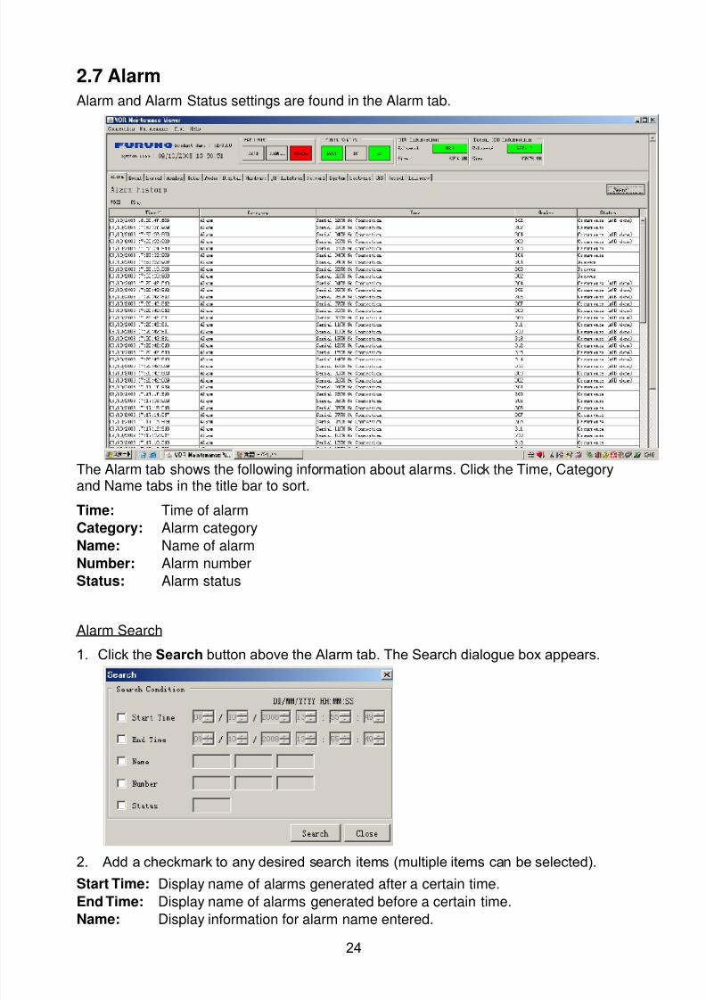
8102019 Ome44376d Vr3000 Mainte Cof26amp3bmol
httpslidepdfcomreaderfullome44376d-vr3000-mainte-cof26amp3bmol 2657
24
27 Alarm
Alarm and Alarm Status settings are found in the Alarm tab
The Alarm tab shows the following information about alarms Click the Time Categoryand Name tabs in the title bar to sort
Time Time of alarm
Category Alarm categoryName Name of alarm
Number Alarm number
Status Alarm status
Alarm Search
1 Click the Search button above the Alarm tab The Search dialogue box appears
2 Add a checkmark to any desired search items (multiple items can be selected)
Start Time Display name of alarms generated after a certain time
End Time Display name of alarms generated before a certain time
Name Display information for alarm name entered
8102019 Ome44376d Vr3000 Mainte Cof26amp3bmol
httpslidepdfcomreaderfullome44376d-vr3000-mainte-cof26amp3bmol 2757
25
Number Display information for alarm number entered
Status Display alarm status for alarm name entered
3 In the checked items column input the desired search items
4 Click the Search Button
Close the Search box to cancel a search
Note During a search the upper left Mode changes from Play to Search andDisplay search related information
8102019 Ome44376d Vr3000 Mainte Cof26amp3bmol
httpslidepdfcomreaderfullome44376d-vr3000-mainte-cof26amp3bmol 2857
26
28 Event
Click the items shown below to sort by item selected
Note You can sort the items in ascending order () descending order () and
initialization order (no symbol)
Time Time an event occurred
Category Category of an event
Name Name of an event
Contents1 Display data associated with log
Contents2 Display data associated with log
Event Search
Do the following to search events
1 Click the Search button on the upper right of the Event tab
2 In the dialogue box add a checkmark to desired search items Multiple items can bechecked
Start Time Display name of event generated after a certain time
End Time Display name of event generated before a certain time
Name Display event names entered
Number Display event numbers entered
Status Display event status entered
Enter information about the checked event to search in the character input box
3 Click the Search button
Note The mode changes from Play to Search when performing a search
8102019 Ome44376d Vr3000 Mainte Cof26amp3bmol
httpslidepdfcomreaderfullome44376d-vr3000-mainte-cof26amp3bmol 2957
27
29 Hardware
The Hardware tab provides information about the system hardware
The buttons in the Setting window work as follows
Self Check Status Display status of self check
CPU Display information about the CPU
Memory Size Display memory size
CPU Board Display status of CPU board
Audio Board Display status of Audio board
Serial Board Display status of Serial board
Radar Interface Board Display status of Radar Interface boardNote Enter and display note
Marked items are optional
8102019 Ome44376d Vr3000 Mainte Cof26amp3bmol
httpslidepdfcomreaderfullome44376d-vr3000-mainte-cof26amp3bmol 3057
28
210 JB
Connect the Junction Box to the DCU before turning on the system
The JB tab functions to set up the Junction Box
The basic procedure for setting up the Junction Box is as follows
1 Click the JB tab2 Select a Junction Box from the Information Area
3 Set up the Junction Box from the Setting Area
4 Click the Set button (Be sure to do this before moving to another channel)5 Click the Check button to perform an inspection on all channels In the Information
Area check column either OK or NG (No Good) is displayed
When using Config Manager with Tabs
1 From the Maintenance menu click VDR Config Management
2 Click the Upload button to record to VDR memory
3 Click the Write buttons to record to DRU Backup HDD and CF
The items in the Setting window work as followsActive Put check in check box to make channel activeNo Display Junction Box numberIP Address Display IP address of Junction Box acquired by VDRMAC Address Display MAC address of Junction Box acquired by VDRCheck Enable and disable equipment checkNote Enter note
Marked items are optional
8102019 Ome44376d Vr3000 Mainte Cof26amp3bmol
httpslidepdfcomreaderfullome44376d-vr3000-mainte-cof26amp3bmol 3157
29
211 Life Time
The Life Time tab controls consumable parts
The basic procedure for using the Life Time tab is as follows
1 Click the Life Time tab
2 Select a Type No in the Information Area3 Set up the chosen part from Setting Area
4 Click the Set button
Note Be sure to click the Set button before moving to set up a different Type
The items in the Setting window work as follows
Type No Enter and display type no
Data Name Enter and display data name
Level Set replacement level Legal Exchange Parts or Normal Exchange Parts
Replace Date Enter and display recommended day of replacement
Lifetime Term Not usedNote Enter and display note
The Status column of the Information Area displays as follows
OK The recommended date of replacement shown in the Replace Date
box in the Information window has not passed
Out of Date The date of replacement has passed
None The date of replacement has not been set
8102019 Ome44376d Vr3000 Mainte Cof26amp3bmol
httpslidepdfcomreaderfullome44376d-vr3000-mainte-cof26amp3bmol 3257
30
212 Network
The Network tab sets the system network
The basic procedure for setting up the system network is as follows
1 Click the Network tab
2 Select a port from the Information Area
3 Set up the network from the Setting Area
4 Click the Set button
Note1 Be sure to click the Set button before moving to set up a different Port
Note2 After setting the system network reboot the VDR to apply the settings
The items in the Setting window work as follows
LAN Type Enter LAN type Public LAN or JB LAN
MAC Address Enter MAC address
IP Address Enter IP address
Subnet Mask Enter subnet mask
Gateway Address Enter gateway address
Live Play Multicast Mode (Only JB LAN) Check box to enable live player multicast
mode
Multicast Address (Only Public LAN) Enter and display live player multicast addressNote Enter note
Marked items are optional
8102019 Ome44376d Vr3000 Mainte Cof26amp3bmol
httpslidepdfcomreaderfullome44376d-vr3000-mainte-cof26amp3bmol 3357
31
213 System
The System tab sets system related functions
The basic procedure for using the System tab is as follows
1 Click the System tab
2 Set up the chosen item from the Setting Area
3 Click the Set button
Note Be sure to click the Set button before moving to a different tab
The items in the Setting window work as follows
VDR Type Enter type of VDR
VDR Model Enter model number of VDR
Radar Interface Check Enable and disable checking of the Radar Interface board
Junction Box Count Enter number of junction boxes in system
DRU Flash Count Enter number of DRU flash disks in system Set 1 when DRU
serial no is 5000 and more Set 3 when DRU serial no is less
than 5000
DRU Capacity Display capacity of DRU
Backup HDD Capacity Display capacity of Backup HDD
VDR Config Version Display version no of VDR
VDR Config Date Display the number of hours the VDR settings have
been saved
VDR Config Code Display configuration identity code
Installation Engineer Enter name of the equipment installer
Installation Company Enter name of installers company
8102019 Ome44376d Vr3000 Mainte Cof26amp3bmol
httpslidepdfcomreaderfullome44376d-vr3000-mainte-cof26amp3bmol 3457
32
Installation Date Enter the date of the installation
MIC Test Time Enter the date of the MIC test
Note Enter note Marked items are optional
USB memory logging Do not check Enable
IEEE1394 BUS Error Auto Restart function Not used
IEEE1394 Active Node Count Do not change the default value of 3 (However set to 5
for serial number 5000 or less of DRU)
IEEE1394 Recover Process Limit Count Do not change the default value of 10
DRU Error Auto Restart function Not used
REBOOT DELAY TIME (sec) Do not change the default value of 10
LIMIT REBOOT COUNT Do not change the default value of 10
Live Player Max Connection Count The max number of Live Player V4 that can be
connected simultaneously The default no is two
but a maximum of five can be set here After you
change this option reboot the VDR to apply the
setting Disconnect the cable connected with
Live Player V4 (PC) from the VDR and thenreconnect it
214 Software
The Software tab sets and display software-related operations
The basic procedure for using the Software tab is as follows
1 Click the Software tab
2 Set up the chosen Item from the Setting Area
3 Click the Set button
8102019 Ome44376d Vr3000 Mainte Cof26amp3bmol
httpslidepdfcomreaderfullome44376d-vr3000-mainte-cof26amp3bmol 3557
33
The items in the Setting window work as follows
VDR System Program Display the VDR system program no
Process Version Display the process version
Power Distribution Unit (PDU) Display the version no of the PDU
Operation System Display the version no of the OS
Audio Driver Display the version no of the audio driverRAP Version Enter the version no of the RAP
AP Version Enter the version no of the AP
JB1-8 Boot Program Display the no of the RJB Boot program for Junction Boxes
1 to 8
JB1-8 App Program Display the no of the RJB App program for Junction Boxes
1 to 8
Watch Dog Interval Do not change the default value of 60 (Enter the process
response time A process is repeated if there is no response
within the time interval set here)
Giveup Interval Do not change the default value of 300 (Enter the restart
watch time The restarting of a process is stopped when the
number of times it has been restarted is exceeded within the
interval set here)
Refork Limit Do not change the default value of 10 (Enter the upper limit
for process restart The restarting of a process is stopped
when the number of times it has been restarted exceeds the
Give up Interval)
Note Enter note
Marked Items are optional
8102019 Ome44376d Vr3000 Mainte Cof26amp3bmol
httpslidepdfcomreaderfullome44376d-vr3000-mainte-cof26amp3bmol 3657
34
215 GPS
The GPS tab sets GPS-related parameters
The basic procedure for using the GPS tab is as follows
1 Click the GPS tab
2 Set up the chosen channel from the Information window3 Set up the chosen item in the Setting Area
4 Click the Set button
5 Repeat steps 2-4 to set up each Channel
6 Click the Check button to perform an inspection on all channels In the Information Area check column either OK or NG (No Good) is displayed
The items in the Setting window work as follows
Priority Display priority order
Date and Time SourceShip Position Source Set GPS source channel (serial channel
number for ZDA sentence)
Check Enable and disable checking
GPS Antenna Position From Bow Enter position of GPS antenna from bow
GPS Antenna Position From Stern Enter position of GPS antenna from stern
GPS Antenna Position From Port Enter position of GPS antenna from port
GPS Antenna Position From Starboard Enter position of GPS antenna from starboard
GPS Failure Threshold If the ZDA is input within the set time limit
the system restarts synchronized If not
input within the time limit the system restarts
without synchronization
8102019 Ome44376d Vr3000 Mainte Cof26amp3bmol
httpslidepdfcomreaderfullome44376d-vr3000-mainte-cof26amp3bmol 3757
35
GPS Delay Time by Time Sync Enter minimum time delay for time
synchronization Time synchronization is started
only in the time set here
GPS Difference Interval The time set here is added to the GPS time to
synchronize the system time Leave at the default
0 value setting
GPS Sync Giveup Time If the system receives the GPS time within the
time set the system synchronizes with the time
When not receiving a signal the system displays
an ldquoerror 26rdquo message
ZDA Timeout Enter value (seconds) for ZDA timeout (234 error)
from GPS
Note Enter and display note
Marked Items are optional
216 VesselThe Vessel tab sets and displays own ships information such as name and IMO number
The basic procedure for using the Vessel tab is as follows
1 Click the Vessel tab
2 Set up information in the Setting window
3 Click the Set button (Be sure to do this before moving to another port)
4 From the Maintenance menu click VDR Config Management and then Config5 Click the Write buttons to save data to the DRU backup HDD CF
The buttons in the Setting window works as follows
Vessel Name Enter name of vessel
Vessel IMO Number Enter IMO number of vessel
Vessel Flag Enter flag of vessel
Approval of Authority Enter name of approving authority
Note Enter note
Marked items are optional
8102019 Ome44376d Vr3000 Mainte Cof26amp3bmol
httpslidepdfcomreaderfullome44376d-vr3000-mainte-cof26amp3bmol 3857
36
217 Delivery
The Delivery tab functions to transmit data from the VDR to a PC via Ethernet LAN Do
not use this function during live connection
The basic procedure for using the Delivery tab is as follows
1 Click the Delivery tab
2 Click the Add button to show the Delivery Config window
3 Select protocol from the Protocol drop-down box (Unicast or Multicast)
4 Enter IP address in the IP address input box
5 Enter port number in the port number input box
6 Click the tab of the data to send (Analog Digital or Serial)
7 Select the channel of the data to send
8 If Serial was selected at step 6 select applicable data sentence from the Inactivewindow Click the right arrow to move the data sentence to the Active window
9 Click the OK button to close the Delivery Config window
10 The settings are listed in a table in the Delivery window Check the checkbox in the
Active column and then click the Set button
The buttons in the Setting window works as follows
Set Save edited settings
Add Create new delivery settings
Modify Modify selected delivery settings
Delete Delete selected delivery settings
8102019 Ome44376d Vr3000 Mainte Cof26amp3bmol
httpslidepdfcomreaderfullome44376d-vr3000-mainte-cof26amp3bmol 3957
37
3 How to Back up Configuration DataThis chapter shows how to back up configuration data to various storage media
Configuration data can be opened with Word Pad or any text editor other than Notepad
31 How to Back up Configuration Data to the Startup CompactFlash (CF)
Back up data to the startup CF after setting the VDR Configuration data is created on the
CF as a configini file
Note When the error shown below occurs during the downloading or uploading of
configuration data check the connection of the DRU Backup HDD and CF and then
upload or download the configuration data again
[CONN] Download failed
[CONN] Could not upload config file
If error occurs again re-install the VDR Maintenance Viewer
Do the following to back up data to a CF
1 Set up parameters on the tabs referring to Chapter 2
2 Click the Maintenance menu
3 Select VDR Config Management
4 Click the Upload button
5 A confirmation box appears click the OK button to start uploading to the VDR
6 Click the Write button where the arrow connects between VDR and DRU BackupHDD
7 A confirmation window appears click the OK button to save the configuration data tothe DRU and Backup HDD
8102019 Ome44376d Vr3000 Mainte Cof26amp3bmol
httpslidepdfcomreaderfullome44376d-vr3000-mainte-cof26amp3bmol 4057
38
8 Click the Write button where the arrow connects between the VDR and CF
9 A confirmation window appears click the OK button to save the configuration data tothe startup CF
10 Check that the PC VDR DRU Backup HDD and CF share the same VDR configcode
32 How to Back up Configuration Data to a PC
Configuration data saved to the PC can be edited with Wordpad and shared with other
vessels For future service ease it is recommended to backup configuration data to the
PC and have the data on board the vessel Also it is recommended to upload this data to
Furuno SMS (Service Management System) If unable to upload to Furuno SMS please
contact the Service Center Furuno Japan
To back up configuration data to the PC do as follows
1 Set up parameters on the tabs referring to Chapter 2
2 Click the Maintenance menu
3 Select VDR Config Management
4 Click the Export to button
5 A confirmation window appears click the OK button
6 Select where to save the data enter file name then click the Open button
7 Confirm that back up file is in the location selected
33 How to restore the default settings
Click the Default button on the VDR Config Management window to restore the default
settings of the DRU Backup HDD CF and VDR Maintenance Viewer
8102019 Ome44376d Vr3000 Mainte Cof26amp3bmol
httpslidepdfcomreaderfullome44376d-vr3000-mainte-cof26amp3bmol 4157
39
4 How to Upload Configuration Datafrom a PCThe procedure below shows how to upload configuration from the PC to aVR-3000VR-3000S
1 Click the Maintenance menu
2 Select VDR Config Management
3 Click the Import from button
4 The Open window appears Select configuration data and then click the Open button
5 Click the Upload button to upload data to the VR-3000VR-3000S
6 Click the Write buttons to save data to the DRU backup HDD and CF
8102019 Ome44376d Vr3000 Mainte Cof26amp3bmol
httpslidepdfcomreaderfullome44376d-vr3000-mainte-cof26amp3bmol 4257
40
5 Media ManagementThe media management feature deletes data from recording media initialization the
system etc There are two method LAN connection and Direct connection The Direct
connection takes longer time than the LAN connection Basically use the LAN connection
method
Note Initialization or creation of recording media is not available when Source Select onthe Live Player V4 is selected to Backup HDD
51 Initialization
This section shows how to delete data from the recording media Configuration data is
not deleted After performing the software configuration delete the data from the DRU
and HDD
Do the following to delete data from the DRU (LAN connection)
1 Set the PlaybackCPU switch in the DCU to the CPU position
2 Use an Ethernet cross cable to connect the PC to J14 (DATA) in the DCU (See page5)
3 Open the Tool menu
4 Select Media Management to open the VDR Media Management window
5 Check that IP address shown in the ldquoLAN Connect to IPrdquo in VDR Media Table Area isthe same as the IP address access point
6 Select ldquoLAN Connect to IPrdquo in the VDR Media Table column
8102019 Ome44376d Vr3000 Mainte Cof26amp3bmol
httpslidepdfcomreaderfullome44376d-vr3000-mainte-cof26amp3bmol 4357
41
7 Click the Analyze button A list of recording media connected to the VDR appears
Put a checkmark in the checkbox of the Select column for the DRU in the Name columnNote If there are several flash memories in the DRU all flash memories are shownCheck all flash memories shown
8 Select ldquoDRU Initializerdquo from the Operation dropdown list in the Operation area
10 Click the Run button
Do the following to delete data from the DRU (Direct connection)
1 Start Live Player V4 software
2 Open the Tool menu and select Source Select Select Live from the pull-downmenu
3 Click the Alarm tab and open Alarm History
4 Set the PlaybackCPU switch in the DCU to the Playback position
5 Wait approx 10 minutes and confirm that Alarm 174 occurs on Alarm History of LivePlayer V4
6 Connect an IEEEE1394 cable between J6 in the DCU and the PC
7 Open the Tool menu
8 Select Media Management to show the VDR Media Management window
9 Select Direct in the VDR Media Table column
10 Click the Analyze button A list of recording media connected to the VDR appears
11 Put a checkmark in the checkbox of the Select column for the DRU in the Namecolumn
Note If there are several flash memories in the DRU all flash memories are shownCheck all flash memories shown
12 Select ldquoDRU Initializerdquo from the Operation dropdown list in the Operation area
13 Enter password in the password column
14 Click the RUN button
8102019 Ome44376d Vr3000 Mainte Cof26amp3bmol
httpslidepdfcomreaderfullome44376d-vr3000-mainte-cof26amp3bmol 4457
42
Delete data from the Backup HDD as follows (LAN connection)
1 Set the PlaybackCPU switch in the DCU to the CPU position
2 Check that an Ethernet cross cable is connected between J14 in the DCU and the PC
3 Open the Tool menu
4 Select Media Management to open the VDR Media Management window
5 Check that IP address shown in the LAN Connect to IP in VDR Media Table Area is
the same as the IP address access point6 Select LAN Connect to IP in the VDR Media Table column
7 Click the Analyze button
8 A list of recording media connected to the VDR appears
9 Put a checkmark in the box of the Select column for the Backup HDD in the Namecolumn Select ldquoBackup HDD Initializerdquo from the Operation dropdown list in theOperation area
10 Click the Run button
Delete data from the Backup HDD as follows (Direct connection)
1 Start Live Player V4 software
2 Open the Tool menu and select Source Select Select Live from the pull-downmenu
3 Click the Alarm tab and open Alarm History
4 Set the PlaybackCPU switch in the DCU to the Playback position
5 Wait approx 10 minutes and confirm that Alarm 174 occurs on Alarm History of LivePlayer V4
6 Connect an IEEE1394 cable between J6 in the DCU and the PC
7 Open the Tool menu
8 Select Media Management to open the VDR Media Management window9 Select Direct in the VDR Media Table window
10 Click the Analyze button A list of recording media connected to the VDR appears
11 Put a checkmark in the check box of the Select column for the Backup HDD in theName column Select ldquoBackup HDD Initializerdquo from the Operation dropdown list in theOperation area
12 Enter password
13 Click the Run button
8102019 Ome44376d Vr3000 Mainte Cof26amp3bmol
httpslidepdfcomreaderfullome44376d-vr3000-mainte-cof26amp3bmol 4557
43
52 CreationThe Creation feature initializes recording media
Note1 This feature deletes ALL configuration data Backup all VDR configuration data
Note2 When you initialize medium that is a different format for the DRU or Backup HDDdelete all partitions with the disk management tool of Windows
Note3 When the Creation is failed try again If you can not initialize recording media tryunder condition as shown below
Do the Creation by the direct connection (When the Creation by the LAN
connection is failed)
Delete all partitions of the DRU or Backup HDD with the disk management tool of
Windows to do the Creation
If the Creation is still failed request service to repairreplace the DRU or Backup
HDD
Initialize the DRU as follows (LAN connection)
1 Set the PlaybackCPU switch in the DCU to the CPU position
2 Check that an Ethernet cross cable is connected between J14 in the DCU and the PC
3 Open the Tool menu
4 Select Media Management to open the VDR Media Management window
5 Check that IP address shown in the LAN Connect to IP in VDR Media Table Area isthe same as the IP address access point
6 Check ldquoLAN Connect to IPrdquo in the VDR Media Table column
7 Click the Analyze button A list of recording media connected to the VDR appears
8 Put a checkmark in the box of the Select column for the DRU in the Name column
Select ldquoDRU Creationrdquo from the Operation dropdown list in the Operation area
9 Click the Run button
Initialize the Backup HDD as follows (LAN connection)
1 To format the Backup HDD place a checkmark in the Select column of the listedrecord media in the Name column of the VDR Media Management dialogue box
2 From the Operation drop down list of the Operation area select ldquoBackup HDDCreation (Radar) or ldquoBackup HDD Creationrdquo
Two partition tools are available for the Backup HDD in the Media Management as
below
Backup HDD creation
This tool is used when the number of the SXGA video signal connected to the BackupHDD is the same as the DRU The same partition is created on both DRU and HDD
(1) When two SXGA video signals are recorded onto the HDD while 9-GB DRU isconnected
(2) When an SXGA video signal is recorded onto the HDD while 6-GB DRU isconnected
Backup HDD creation (radar)
This tool is used when two SXGA video signals are recorded onto the HDD with 6-GB
DRU connected The HDD has an area (radar) to record the second radar signal inaddition to the same partition as the DRU This tool cannot be used when 9-GB DRUis connected
3 Press the Run Button
8102019 Ome44376d Vr3000 Mainte Cof26amp3bmol
httpslidepdfcomreaderfullome44376d-vr3000-mainte-cof26amp3bmol 4657
44
Initialize the DRU as follows (Direct connection)
1 Start Live Player V4 software
2 Open the Tool menu and select Source Select Select Live from the pull-downmenu
3 Click the Alarm tab and open Alarm History
4 Set the PlaybackCPU switch in the DCU to the Playback position
5 Wait approx 10 minutes and confirm that Alarm 174 occurs on Alarm History of LivePlayer V4
6 Connect an IEEE1394 cable between J6 in the DCU and the PC
7 Open the Tool menu
8 Select Media Management to open the VDR Media Management window
9 Select Direct in the VDR Media Table window
10 Click the Analyze button A list of recording media connected to the VDR appears
11 Put a checkmark in the box of the Select column for the DRU and the desiredrecording media in the Name column In the Operation dropdown list of the Operationarea select ldquoDRU Creationrdquo
12 Enter password in the password column
13 Click the Run button
Initialize the Backup HDD as follows (Direct Connection)
1 To format the Backup HDD place a checkmark in the Select column of the listedrecord media in the Name column of the VDR Media Management dialogue box
2 From the Operation column of the Operation area select ldquoBackup HDD Creation(Radar) or ldquoBackup HDD Creationrdquo
Backup HDD creation
This tool is used when the number of the SXGA video signal connected to the BackupHDD is the same as the DRU The same partition is created on both DRU and HDD
(1) When two SXGA video signals are recorded onto the HDD while 9-GB DRU is
connected
(2) When an SXGA video signal is recorded onto the HDD while 6-GB DRU is
connected
Backup HDD creation (radar)
This tool is used when two SXGA video signals are recorded onto the HDD with 6-GBDRU connected The HDD has an area (radar) to record the second radar signal inaddition to the same partition as the DRU This tool cannot be used when 9-GB DRUis connected
3 Enter the password in the Password column
4 Press the Run Button
8102019 Ome44376d Vr3000 Mainte Cof26amp3bmol
httpslidepdfcomreaderfullome44376d-vr3000-mainte-cof26amp3bmol 4757
45
53 How to Enable Recording Area on the Backup HDD
This function enables writing over a recording area To prevent falsification of data all
recording areas must be saved otherwise this function is disabled To use this function push
the SAVE button Save the data before doing this procedure
Note Software version 135 or higher can enable writing over a recording area even if
all recording areas are not saved
Recording enable (LAN connection)
1 Set the PlaybackCPU switch in the DCU to the CPU position
2 Check that an Ethernet cross cable is connected between J14 in the DCU and the PC
3 Open the Tool menu
4 Select Media Management to open the VDR Media Management window
5 Check that IP address shown in the ldquoLAN Connect to IPrdquo in VDR Media Table Area isthe same as the IP address access point
6 Select ldquoLAN Connect to IPrdquo in the VDR Media Table column7 Click the Analyze button A list of recording media connected to the VDR appears
8 Put a checkmark in the box of the Select column for the Backup HDD in the Namecolumn
9 Select ldquoBackup HDD Recording Area Enablerdquo from the Operation dropdown list in theOperation area
10 Click the Run button
Recording enable (Direct connection)
1 Start Live Player V4 software
2 Open the Tool menu and select Source Select Select Live from the pull-down menu3 Click the Alarm tab and open Alarm History
4 Set the PlaybackCPU switch in the DCU to the Playback position
5 Wait approx 10 minutes and confirm that Alarm 174 occurs on Alarm History of LivePlayer V4
6 Connect an IEEE1394 cable between J6 in the DCU and the PC
7 Open the Tool menu
8 Select Media Management to open the VDR Media Management window
9 Select Direct in the VDR Media Table window
10 Click the Analyze button A list of recording media connected to the VDR appears11 Put a checkmark in the box of the Select column for the Backup HDD in the Name
column
12 Select ldquoBackup HDD Recording Area Enablerdquo from the Operation dropdown list in theOperation area
13 Enter password
14 Click the Run button
8102019 Ome44376d Vr3000 Mainte Cof26amp3bmol
httpslidepdfcomreaderfullome44376d-vr3000-mainte-cof26amp3bmol 4857
46
6 Other Functions
61 Software Management
The software download feature downloads VDR system software to the PC
To download software
1 Click the Maintenance menu
2 From the Software Management menu click Software Download to show theSoftware Download window
3 Enter the IP address 1000100 in the IP address box in the Update Server area
4 Click the Download Software button
5 The confirmation window appears click the OK button
The Software Backup Execute window shows the results of the download
Software is downloaded to C Program Files VDR Viewer Viewer Backup The software file
name is vdrtar
To Update Software
VDR system program version 16x can update the software with the procedure shownbelow
Note Do not update the file downloaded in procedures above
1 Click the Maintenance menu
2 From the Software Management menu click Software Upload to show the SoftwareUpload area
3 Click the Select button to show the Open window
4 Select update file (vdrtar) and click the Open button
8102019 Ome44376d Vr3000 Mainte Cof26amp3bmol
httpslidepdfcomreaderfullome44376d-vr3000-mainte-cof26amp3bmol 4957
47
5 Check the displayed Software information is correct
6 Enter the IP address 1000100 in the IP address box in the Update Server area
7 Enter password
8 Click the Update button
After the updating is completed the VDR is automatically restarted
Note Click the Restore button on the Software Update window to restore previoussoftware version This feature is available after updating the software
62 Password Management
The password can be changed for a serviceman to access the equipment Contact
FURUNO to get the default password to use during installation
Serviceman password
1 Click the Maintenance menu2 Select Change Serviceman Password from Password Management to show the
Change Serviceman Password window
3 Enter current password in the Old Password box
4 Enter the new password in the New Password box of the Change Password area
5 Enter new password again in the Confirm New Password box
6 Click the OK button
Audio password
The audio password set at the VDR Maintenance Viewer can be removed to enable
audio access without password1 Click the Maintenance menu
2 Select Change Audio Password from Password Management to show the Change Audio Password window
3 The confirmation window appears click the OK button
8102019 Ome44376d Vr3000 Mainte Cof26amp3bmol
httpslidepdfcomreaderfullome44376d-vr3000-mainte-cof26amp3bmol 5057
48
63 Record ComparisonThe integrity of the DRU and Backup HDD recordings can be compared This function isused by the RampD engineer for debugging
Follow the procedure as shown below
1 Click the Maintenance menu2 Select Record Comparison to show the Record Comparison window
The results are shown every 15 seconds in the Record Comparison window
8102019 Ome44376d Vr3000 Mainte Cof26amp3bmol
httpslidepdfcomreaderfullome44376d-vr3000-mainte-cof26amp3bmol 5157
49
64 Software History
This section shows you to save and configure software history (communications record)
How to save software history
Note When the error dialog appears while saving the software history restart the VDR
Maintenance Viewer
1 Click the Maintenance menu
2 Select Software History Collect
3 Click the Select button The Open dialog box appears
4 Select where to save the data then click the Open button
5 Select desired save condition then click the OK buttonNone No savingAt Once Save the software history manually Saving begins as soon as the OK button is clickedPeriodic For debugging Do not use otherwise The intervals are 30 sec 60 secand 120 secAlarm Detection For debugging Do not use otherwise Software history is savedwhen specified alarm is released Enter alarm number
How to configure software communications record
The RampD engineer uses this function for debugging Do not do this procedure unless
required Malfunction can result
1 Click the Maintenance menu
2 Select Software History Config
3 Do the followingProcess Select the type of communications record to save ALL saves allcommunications records
Detail Hide or show detailed information4 Click the Send button
8102019 Ome44376d Vr3000 Mainte Cof26amp3bmol
httpslidepdfcomreaderfullome44376d-vr3000-mainte-cof26amp3bmol 5257
50
65 Easy SetupThis feature sets equipment settings in batch and creates a data file of those settings
Default template The default template is created with the settings entered at installation
1 Click the Maintenance menu
2 Select Easy Setup to show the Template Selection window
3 Select Default Template
4 Click the Start button to show the Easy Setup window
5 Right click the channels (Radar Audio Digital Serial Analog) then select Edit toshow the Equipment Selection window
6 From the Equipment Directory window select equipment connected to the selectedchannel and then click the OK button
7 Repeat steps 5 and 6 to select equipment settings for each channel
8 Click the Save button in the Easy Setup window to show the Save window
9 Select where to save the file and enter file name
10 Click the Save button
8102019 Ome44376d Vr3000 Mainte Cof26amp3bmol
httpslidepdfcomreaderfullome44376d-vr3000-mainte-cof26amp3bmol 5357
51
Specific template Use a file already created
1 Click the Maintenance menu
2 Select Easy Setup to show the Template Selection window
3 Check Specified Template
4 Click the Select button and then select the file to edit
5 Click the Start button to show the Easy Setup window
6 Right click the channels (Radar Audio Digital Serial Analog) then select Edit toshow the Equipment Selection window
7 From the Equipment Directory window select equipment connected to the selectedchannel and then click the OK button
8 Repeat steps 6 and 7 to select equipment settings for each channel
9 Click the Save button in the Easy Setup window to show the Save window
10Select where to save the file and enter file name
11 Click the Save button
66 Equipment Management
This feature controls the import and export of equipment settings
Import data file
Import data files of equipment settings created in Easy Setup etc to the VDR
1 Click the Maintenance menu
2 Select Import from Equipment Management to show the Open window
3 Select the data file to import and click Open
Export data file
Export data files of equipment settings from the VDR to a PC
1 Click the Maintenance menu
2 Select Export from Equipment Management to show the Save window
3 Enter file name
4 Click the Save button
8102019 Ome44376d Vr3000 Mainte Cof26amp3bmol
httpslidepdfcomreaderfullome44376d-vr3000-mainte-cof26amp3bmol 5457
52
67 PC_RAP
This feature enables the same operation of the RAP (Remote Alarm Panel) from a PC
Select PC_RAP from the Tool menu to show the PC_RAP window
The buttons in the PC_RAP window function as shown below
SAVE Stop recording in the area where recording is currently being done
ACK Silence audio alarm
The PC_RAP display shows the following information with LEDs
RAP_LEDs Display the status of LEDs on the RAPSave The Save button blinks yellow when pushed When the 4 memory
areas have data recorded to them the Save button lights orange when
pushed
Normal Lights (green) where there are no unconfirmed or not restored
alarms
Error Flashes (red) for not confirmed alarm Lights (red) for unrestored
alarm
8102019 Ome44376d Vr3000 Mainte Cof26amp3bmol
httpslidepdfcomreaderfullome44376d-vr3000-mainte-cof26amp3bmol 5557
53
Backup HDD Information Display status of backup HDD
Selected Display current recording area and its status in green for
normal operation and in red for abnormal operation
Size Display capacity of backup HDD
Alarm area displays unconfirmed alarms
Time Display time alarm was generatedNumber Display number of alarm
Name Display name of alarm
Pending Alarm displays the unrestored alarms out of confirmed alarms only
Time Display time alarm was generated
Number Display number of alarm
Name Display name of alarm
8102019 Ome44376d Vr3000 Mainte Cof26amp3bmol
httpslidepdfcomreaderfullome44376d-vr3000-mainte-cof26amp3bmol 5657
54
68 Other
Status Monitor
The status monitor feature provides comprehensive data about the status of the VDR
From the menu bar click Toolgt Status Monitor to show the Status Monitor window
The buttons in the Status Monitor window work as shown below
Reload Settings for automatic refreshing of the status monitor
ON Turn automatic refresh OFF
OFF The Status Monitor is refreshed every five seconds
Save Available when Reload ON is selected The contents of the Status Monitor can be
saved to a text fileUpdate Update the Status Monitor display
Close Close the Status Monitor display
8102019 Ome44376d Vr3000 Mainte Cof26amp3bmol
httpslidepdfcomreaderfullome44376d-vr3000-mainte-cof26amp3bmol 5757
VDR Error List
This feature compiles all the errors shown on the RAP for easy reference
Access from MenugtToolgtVDR Error List
The VDR error list contains the following information
NO Display the number of the error
Title Display the name of the error
Detail Display details about the error
Exchange Check
This feature removes the alarms generated when replacing the DRU or backup HDD
Access MenugtToolgtExchange Check select either DRU or Backup HDD and click OK
Reboot
Reboot the VDR
8102019 Ome44376d Vr3000 Mainte Cof26amp3bmol
httpslidepdfcomreaderfullome44376d-vr3000-mainte-cof26amp3bmol 2757
25
Number Display information for alarm number entered
Status Display alarm status for alarm name entered
3 In the checked items column input the desired search items
4 Click the Search Button
Close the Search box to cancel a search
Note During a search the upper left Mode changes from Play to Search andDisplay search related information
8102019 Ome44376d Vr3000 Mainte Cof26amp3bmol
httpslidepdfcomreaderfullome44376d-vr3000-mainte-cof26amp3bmol 2857
26
28 Event
Click the items shown below to sort by item selected
Note You can sort the items in ascending order () descending order () and
initialization order (no symbol)
Time Time an event occurred
Category Category of an event
Name Name of an event
Contents1 Display data associated with log
Contents2 Display data associated with log
Event Search
Do the following to search events
1 Click the Search button on the upper right of the Event tab
2 In the dialogue box add a checkmark to desired search items Multiple items can bechecked
Start Time Display name of event generated after a certain time
End Time Display name of event generated before a certain time
Name Display event names entered
Number Display event numbers entered
Status Display event status entered
Enter information about the checked event to search in the character input box
3 Click the Search button
Note The mode changes from Play to Search when performing a search
8102019 Ome44376d Vr3000 Mainte Cof26amp3bmol
httpslidepdfcomreaderfullome44376d-vr3000-mainte-cof26amp3bmol 2957
27
29 Hardware
The Hardware tab provides information about the system hardware
The buttons in the Setting window work as follows
Self Check Status Display status of self check
CPU Display information about the CPU
Memory Size Display memory size
CPU Board Display status of CPU board
Audio Board Display status of Audio board
Serial Board Display status of Serial board
Radar Interface Board Display status of Radar Interface boardNote Enter and display note
Marked items are optional
8102019 Ome44376d Vr3000 Mainte Cof26amp3bmol
httpslidepdfcomreaderfullome44376d-vr3000-mainte-cof26amp3bmol 3057
28
210 JB
Connect the Junction Box to the DCU before turning on the system
The JB tab functions to set up the Junction Box
The basic procedure for setting up the Junction Box is as follows
1 Click the JB tab2 Select a Junction Box from the Information Area
3 Set up the Junction Box from the Setting Area
4 Click the Set button (Be sure to do this before moving to another channel)5 Click the Check button to perform an inspection on all channels In the Information
Area check column either OK or NG (No Good) is displayed
When using Config Manager with Tabs
1 From the Maintenance menu click VDR Config Management
2 Click the Upload button to record to VDR memory
3 Click the Write buttons to record to DRU Backup HDD and CF
The items in the Setting window work as followsActive Put check in check box to make channel activeNo Display Junction Box numberIP Address Display IP address of Junction Box acquired by VDRMAC Address Display MAC address of Junction Box acquired by VDRCheck Enable and disable equipment checkNote Enter note
Marked items are optional
8102019 Ome44376d Vr3000 Mainte Cof26amp3bmol
httpslidepdfcomreaderfullome44376d-vr3000-mainte-cof26amp3bmol 3157
29
211 Life Time
The Life Time tab controls consumable parts
The basic procedure for using the Life Time tab is as follows
1 Click the Life Time tab
2 Select a Type No in the Information Area3 Set up the chosen part from Setting Area
4 Click the Set button
Note Be sure to click the Set button before moving to set up a different Type
The items in the Setting window work as follows
Type No Enter and display type no
Data Name Enter and display data name
Level Set replacement level Legal Exchange Parts or Normal Exchange Parts
Replace Date Enter and display recommended day of replacement
Lifetime Term Not usedNote Enter and display note
The Status column of the Information Area displays as follows
OK The recommended date of replacement shown in the Replace Date
box in the Information window has not passed
Out of Date The date of replacement has passed
None The date of replacement has not been set
8102019 Ome44376d Vr3000 Mainte Cof26amp3bmol
httpslidepdfcomreaderfullome44376d-vr3000-mainte-cof26amp3bmol 3257
30
212 Network
The Network tab sets the system network
The basic procedure for setting up the system network is as follows
1 Click the Network tab
2 Select a port from the Information Area
3 Set up the network from the Setting Area
4 Click the Set button
Note1 Be sure to click the Set button before moving to set up a different Port
Note2 After setting the system network reboot the VDR to apply the settings
The items in the Setting window work as follows
LAN Type Enter LAN type Public LAN or JB LAN
MAC Address Enter MAC address
IP Address Enter IP address
Subnet Mask Enter subnet mask
Gateway Address Enter gateway address
Live Play Multicast Mode (Only JB LAN) Check box to enable live player multicast
mode
Multicast Address (Only Public LAN) Enter and display live player multicast addressNote Enter note
Marked items are optional
8102019 Ome44376d Vr3000 Mainte Cof26amp3bmol
httpslidepdfcomreaderfullome44376d-vr3000-mainte-cof26amp3bmol 3357
31
213 System
The System tab sets system related functions
The basic procedure for using the System tab is as follows
1 Click the System tab
2 Set up the chosen item from the Setting Area
3 Click the Set button
Note Be sure to click the Set button before moving to a different tab
The items in the Setting window work as follows
VDR Type Enter type of VDR
VDR Model Enter model number of VDR
Radar Interface Check Enable and disable checking of the Radar Interface board
Junction Box Count Enter number of junction boxes in system
DRU Flash Count Enter number of DRU flash disks in system Set 1 when DRU
serial no is 5000 and more Set 3 when DRU serial no is less
than 5000
DRU Capacity Display capacity of DRU
Backup HDD Capacity Display capacity of Backup HDD
VDR Config Version Display version no of VDR
VDR Config Date Display the number of hours the VDR settings have
been saved
VDR Config Code Display configuration identity code
Installation Engineer Enter name of the equipment installer
Installation Company Enter name of installers company
8102019 Ome44376d Vr3000 Mainte Cof26amp3bmol
httpslidepdfcomreaderfullome44376d-vr3000-mainte-cof26amp3bmol 3457
32
Installation Date Enter the date of the installation
MIC Test Time Enter the date of the MIC test
Note Enter note Marked items are optional
USB memory logging Do not check Enable
IEEE1394 BUS Error Auto Restart function Not used
IEEE1394 Active Node Count Do not change the default value of 3 (However set to 5
for serial number 5000 or less of DRU)
IEEE1394 Recover Process Limit Count Do not change the default value of 10
DRU Error Auto Restart function Not used
REBOOT DELAY TIME (sec) Do not change the default value of 10
LIMIT REBOOT COUNT Do not change the default value of 10
Live Player Max Connection Count The max number of Live Player V4 that can be
connected simultaneously The default no is two
but a maximum of five can be set here After you
change this option reboot the VDR to apply the
setting Disconnect the cable connected with
Live Player V4 (PC) from the VDR and thenreconnect it
214 Software
The Software tab sets and display software-related operations
The basic procedure for using the Software tab is as follows
1 Click the Software tab
2 Set up the chosen Item from the Setting Area
3 Click the Set button
8102019 Ome44376d Vr3000 Mainte Cof26amp3bmol
httpslidepdfcomreaderfullome44376d-vr3000-mainte-cof26amp3bmol 3557
33
The items in the Setting window work as follows
VDR System Program Display the VDR system program no
Process Version Display the process version
Power Distribution Unit (PDU) Display the version no of the PDU
Operation System Display the version no of the OS
Audio Driver Display the version no of the audio driverRAP Version Enter the version no of the RAP
AP Version Enter the version no of the AP
JB1-8 Boot Program Display the no of the RJB Boot program for Junction Boxes
1 to 8
JB1-8 App Program Display the no of the RJB App program for Junction Boxes
1 to 8
Watch Dog Interval Do not change the default value of 60 (Enter the process
response time A process is repeated if there is no response
within the time interval set here)
Giveup Interval Do not change the default value of 300 (Enter the restart
watch time The restarting of a process is stopped when the
number of times it has been restarted is exceeded within the
interval set here)
Refork Limit Do not change the default value of 10 (Enter the upper limit
for process restart The restarting of a process is stopped
when the number of times it has been restarted exceeds the
Give up Interval)
Note Enter note
Marked Items are optional
8102019 Ome44376d Vr3000 Mainte Cof26amp3bmol
httpslidepdfcomreaderfullome44376d-vr3000-mainte-cof26amp3bmol 3657
34
215 GPS
The GPS tab sets GPS-related parameters
The basic procedure for using the GPS tab is as follows
1 Click the GPS tab
2 Set up the chosen channel from the Information window3 Set up the chosen item in the Setting Area
4 Click the Set button
5 Repeat steps 2-4 to set up each Channel
6 Click the Check button to perform an inspection on all channels In the Information Area check column either OK or NG (No Good) is displayed
The items in the Setting window work as follows
Priority Display priority order
Date and Time SourceShip Position Source Set GPS source channel (serial channel
number for ZDA sentence)
Check Enable and disable checking
GPS Antenna Position From Bow Enter position of GPS antenna from bow
GPS Antenna Position From Stern Enter position of GPS antenna from stern
GPS Antenna Position From Port Enter position of GPS antenna from port
GPS Antenna Position From Starboard Enter position of GPS antenna from starboard
GPS Failure Threshold If the ZDA is input within the set time limit
the system restarts synchronized If not
input within the time limit the system restarts
without synchronization
8102019 Ome44376d Vr3000 Mainte Cof26amp3bmol
httpslidepdfcomreaderfullome44376d-vr3000-mainte-cof26amp3bmol 3757
35
GPS Delay Time by Time Sync Enter minimum time delay for time
synchronization Time synchronization is started
only in the time set here
GPS Difference Interval The time set here is added to the GPS time to
synchronize the system time Leave at the default
0 value setting
GPS Sync Giveup Time If the system receives the GPS time within the
time set the system synchronizes with the time
When not receiving a signal the system displays
an ldquoerror 26rdquo message
ZDA Timeout Enter value (seconds) for ZDA timeout (234 error)
from GPS
Note Enter and display note
Marked Items are optional
216 VesselThe Vessel tab sets and displays own ships information such as name and IMO number
The basic procedure for using the Vessel tab is as follows
1 Click the Vessel tab
2 Set up information in the Setting window
3 Click the Set button (Be sure to do this before moving to another port)
4 From the Maintenance menu click VDR Config Management and then Config5 Click the Write buttons to save data to the DRU backup HDD CF
The buttons in the Setting window works as follows
Vessel Name Enter name of vessel
Vessel IMO Number Enter IMO number of vessel
Vessel Flag Enter flag of vessel
Approval of Authority Enter name of approving authority
Note Enter note
Marked items are optional
8102019 Ome44376d Vr3000 Mainte Cof26amp3bmol
httpslidepdfcomreaderfullome44376d-vr3000-mainte-cof26amp3bmol 3857
36
217 Delivery
The Delivery tab functions to transmit data from the VDR to a PC via Ethernet LAN Do
not use this function during live connection
The basic procedure for using the Delivery tab is as follows
1 Click the Delivery tab
2 Click the Add button to show the Delivery Config window
3 Select protocol from the Protocol drop-down box (Unicast or Multicast)
4 Enter IP address in the IP address input box
5 Enter port number in the port number input box
6 Click the tab of the data to send (Analog Digital or Serial)
7 Select the channel of the data to send
8 If Serial was selected at step 6 select applicable data sentence from the Inactivewindow Click the right arrow to move the data sentence to the Active window
9 Click the OK button to close the Delivery Config window
10 The settings are listed in a table in the Delivery window Check the checkbox in the
Active column and then click the Set button
The buttons in the Setting window works as follows
Set Save edited settings
Add Create new delivery settings
Modify Modify selected delivery settings
Delete Delete selected delivery settings
8102019 Ome44376d Vr3000 Mainte Cof26amp3bmol
httpslidepdfcomreaderfullome44376d-vr3000-mainte-cof26amp3bmol 3957
37
3 How to Back up Configuration DataThis chapter shows how to back up configuration data to various storage media
Configuration data can be opened with Word Pad or any text editor other than Notepad
31 How to Back up Configuration Data to the Startup CompactFlash (CF)
Back up data to the startup CF after setting the VDR Configuration data is created on the
CF as a configini file
Note When the error shown below occurs during the downloading or uploading of
configuration data check the connection of the DRU Backup HDD and CF and then
upload or download the configuration data again
[CONN] Download failed
[CONN] Could not upload config file
If error occurs again re-install the VDR Maintenance Viewer
Do the following to back up data to a CF
1 Set up parameters on the tabs referring to Chapter 2
2 Click the Maintenance menu
3 Select VDR Config Management
4 Click the Upload button
5 A confirmation box appears click the OK button to start uploading to the VDR
6 Click the Write button where the arrow connects between VDR and DRU BackupHDD
7 A confirmation window appears click the OK button to save the configuration data tothe DRU and Backup HDD
8102019 Ome44376d Vr3000 Mainte Cof26amp3bmol
httpslidepdfcomreaderfullome44376d-vr3000-mainte-cof26amp3bmol 4057
38
8 Click the Write button where the arrow connects between the VDR and CF
9 A confirmation window appears click the OK button to save the configuration data tothe startup CF
10 Check that the PC VDR DRU Backup HDD and CF share the same VDR configcode
32 How to Back up Configuration Data to a PC
Configuration data saved to the PC can be edited with Wordpad and shared with other
vessels For future service ease it is recommended to backup configuration data to the
PC and have the data on board the vessel Also it is recommended to upload this data to
Furuno SMS (Service Management System) If unable to upload to Furuno SMS please
contact the Service Center Furuno Japan
To back up configuration data to the PC do as follows
1 Set up parameters on the tabs referring to Chapter 2
2 Click the Maintenance menu
3 Select VDR Config Management
4 Click the Export to button
5 A confirmation window appears click the OK button
6 Select where to save the data enter file name then click the Open button
7 Confirm that back up file is in the location selected
33 How to restore the default settings
Click the Default button on the VDR Config Management window to restore the default
settings of the DRU Backup HDD CF and VDR Maintenance Viewer
8102019 Ome44376d Vr3000 Mainte Cof26amp3bmol
httpslidepdfcomreaderfullome44376d-vr3000-mainte-cof26amp3bmol 4157
39
4 How to Upload Configuration Datafrom a PCThe procedure below shows how to upload configuration from the PC to aVR-3000VR-3000S
1 Click the Maintenance menu
2 Select VDR Config Management
3 Click the Import from button
4 The Open window appears Select configuration data and then click the Open button
5 Click the Upload button to upload data to the VR-3000VR-3000S
6 Click the Write buttons to save data to the DRU backup HDD and CF
8102019 Ome44376d Vr3000 Mainte Cof26amp3bmol
httpslidepdfcomreaderfullome44376d-vr3000-mainte-cof26amp3bmol 4257
40
5 Media ManagementThe media management feature deletes data from recording media initialization the
system etc There are two method LAN connection and Direct connection The Direct
connection takes longer time than the LAN connection Basically use the LAN connection
method
Note Initialization or creation of recording media is not available when Source Select onthe Live Player V4 is selected to Backup HDD
51 Initialization
This section shows how to delete data from the recording media Configuration data is
not deleted After performing the software configuration delete the data from the DRU
and HDD
Do the following to delete data from the DRU (LAN connection)
1 Set the PlaybackCPU switch in the DCU to the CPU position
2 Use an Ethernet cross cable to connect the PC to J14 (DATA) in the DCU (See page5)
3 Open the Tool menu
4 Select Media Management to open the VDR Media Management window
5 Check that IP address shown in the ldquoLAN Connect to IPrdquo in VDR Media Table Area isthe same as the IP address access point
6 Select ldquoLAN Connect to IPrdquo in the VDR Media Table column
8102019 Ome44376d Vr3000 Mainte Cof26amp3bmol
httpslidepdfcomreaderfullome44376d-vr3000-mainte-cof26amp3bmol 4357
41
7 Click the Analyze button A list of recording media connected to the VDR appears
Put a checkmark in the checkbox of the Select column for the DRU in the Name columnNote If there are several flash memories in the DRU all flash memories are shownCheck all flash memories shown
8 Select ldquoDRU Initializerdquo from the Operation dropdown list in the Operation area
10 Click the Run button
Do the following to delete data from the DRU (Direct connection)
1 Start Live Player V4 software
2 Open the Tool menu and select Source Select Select Live from the pull-downmenu
3 Click the Alarm tab and open Alarm History
4 Set the PlaybackCPU switch in the DCU to the Playback position
5 Wait approx 10 minutes and confirm that Alarm 174 occurs on Alarm History of LivePlayer V4
6 Connect an IEEEE1394 cable between J6 in the DCU and the PC
7 Open the Tool menu
8 Select Media Management to show the VDR Media Management window
9 Select Direct in the VDR Media Table column
10 Click the Analyze button A list of recording media connected to the VDR appears
11 Put a checkmark in the checkbox of the Select column for the DRU in the Namecolumn
Note If there are several flash memories in the DRU all flash memories are shownCheck all flash memories shown
12 Select ldquoDRU Initializerdquo from the Operation dropdown list in the Operation area
13 Enter password in the password column
14 Click the RUN button
8102019 Ome44376d Vr3000 Mainte Cof26amp3bmol
httpslidepdfcomreaderfullome44376d-vr3000-mainte-cof26amp3bmol 4457
42
Delete data from the Backup HDD as follows (LAN connection)
1 Set the PlaybackCPU switch in the DCU to the CPU position
2 Check that an Ethernet cross cable is connected between J14 in the DCU and the PC
3 Open the Tool menu
4 Select Media Management to open the VDR Media Management window
5 Check that IP address shown in the LAN Connect to IP in VDR Media Table Area is
the same as the IP address access point6 Select LAN Connect to IP in the VDR Media Table column
7 Click the Analyze button
8 A list of recording media connected to the VDR appears
9 Put a checkmark in the box of the Select column for the Backup HDD in the Namecolumn Select ldquoBackup HDD Initializerdquo from the Operation dropdown list in theOperation area
10 Click the Run button
Delete data from the Backup HDD as follows (Direct connection)
1 Start Live Player V4 software
2 Open the Tool menu and select Source Select Select Live from the pull-downmenu
3 Click the Alarm tab and open Alarm History
4 Set the PlaybackCPU switch in the DCU to the Playback position
5 Wait approx 10 minutes and confirm that Alarm 174 occurs on Alarm History of LivePlayer V4
6 Connect an IEEE1394 cable between J6 in the DCU and the PC
7 Open the Tool menu
8 Select Media Management to open the VDR Media Management window9 Select Direct in the VDR Media Table window
10 Click the Analyze button A list of recording media connected to the VDR appears
11 Put a checkmark in the check box of the Select column for the Backup HDD in theName column Select ldquoBackup HDD Initializerdquo from the Operation dropdown list in theOperation area
12 Enter password
13 Click the Run button
8102019 Ome44376d Vr3000 Mainte Cof26amp3bmol
httpslidepdfcomreaderfullome44376d-vr3000-mainte-cof26amp3bmol 4557
43
52 CreationThe Creation feature initializes recording media
Note1 This feature deletes ALL configuration data Backup all VDR configuration data
Note2 When you initialize medium that is a different format for the DRU or Backup HDDdelete all partitions with the disk management tool of Windows
Note3 When the Creation is failed try again If you can not initialize recording media tryunder condition as shown below
Do the Creation by the direct connection (When the Creation by the LAN
connection is failed)
Delete all partitions of the DRU or Backup HDD with the disk management tool of
Windows to do the Creation
If the Creation is still failed request service to repairreplace the DRU or Backup
HDD
Initialize the DRU as follows (LAN connection)
1 Set the PlaybackCPU switch in the DCU to the CPU position
2 Check that an Ethernet cross cable is connected between J14 in the DCU and the PC
3 Open the Tool menu
4 Select Media Management to open the VDR Media Management window
5 Check that IP address shown in the LAN Connect to IP in VDR Media Table Area isthe same as the IP address access point
6 Check ldquoLAN Connect to IPrdquo in the VDR Media Table column
7 Click the Analyze button A list of recording media connected to the VDR appears
8 Put a checkmark in the box of the Select column for the DRU in the Name column
Select ldquoDRU Creationrdquo from the Operation dropdown list in the Operation area
9 Click the Run button
Initialize the Backup HDD as follows (LAN connection)
1 To format the Backup HDD place a checkmark in the Select column of the listedrecord media in the Name column of the VDR Media Management dialogue box
2 From the Operation drop down list of the Operation area select ldquoBackup HDDCreation (Radar) or ldquoBackup HDD Creationrdquo
Two partition tools are available for the Backup HDD in the Media Management as
below
Backup HDD creation
This tool is used when the number of the SXGA video signal connected to the BackupHDD is the same as the DRU The same partition is created on both DRU and HDD
(1) When two SXGA video signals are recorded onto the HDD while 9-GB DRU isconnected
(2) When an SXGA video signal is recorded onto the HDD while 6-GB DRU isconnected
Backup HDD creation (radar)
This tool is used when two SXGA video signals are recorded onto the HDD with 6-GB
DRU connected The HDD has an area (radar) to record the second radar signal inaddition to the same partition as the DRU This tool cannot be used when 9-GB DRUis connected
3 Press the Run Button
8102019 Ome44376d Vr3000 Mainte Cof26amp3bmol
httpslidepdfcomreaderfullome44376d-vr3000-mainte-cof26amp3bmol 4657
44
Initialize the DRU as follows (Direct connection)
1 Start Live Player V4 software
2 Open the Tool menu and select Source Select Select Live from the pull-downmenu
3 Click the Alarm tab and open Alarm History
4 Set the PlaybackCPU switch in the DCU to the Playback position
5 Wait approx 10 minutes and confirm that Alarm 174 occurs on Alarm History of LivePlayer V4
6 Connect an IEEE1394 cable between J6 in the DCU and the PC
7 Open the Tool menu
8 Select Media Management to open the VDR Media Management window
9 Select Direct in the VDR Media Table window
10 Click the Analyze button A list of recording media connected to the VDR appears
11 Put a checkmark in the box of the Select column for the DRU and the desiredrecording media in the Name column In the Operation dropdown list of the Operationarea select ldquoDRU Creationrdquo
12 Enter password in the password column
13 Click the Run button
Initialize the Backup HDD as follows (Direct Connection)
1 To format the Backup HDD place a checkmark in the Select column of the listedrecord media in the Name column of the VDR Media Management dialogue box
2 From the Operation column of the Operation area select ldquoBackup HDD Creation(Radar) or ldquoBackup HDD Creationrdquo
Backup HDD creation
This tool is used when the number of the SXGA video signal connected to the BackupHDD is the same as the DRU The same partition is created on both DRU and HDD
(1) When two SXGA video signals are recorded onto the HDD while 9-GB DRU is
connected
(2) When an SXGA video signal is recorded onto the HDD while 6-GB DRU is
connected
Backup HDD creation (radar)
This tool is used when two SXGA video signals are recorded onto the HDD with 6-GBDRU connected The HDD has an area (radar) to record the second radar signal inaddition to the same partition as the DRU This tool cannot be used when 9-GB DRUis connected
3 Enter the password in the Password column
4 Press the Run Button
8102019 Ome44376d Vr3000 Mainte Cof26amp3bmol
httpslidepdfcomreaderfullome44376d-vr3000-mainte-cof26amp3bmol 4757
45
53 How to Enable Recording Area on the Backup HDD
This function enables writing over a recording area To prevent falsification of data all
recording areas must be saved otherwise this function is disabled To use this function push
the SAVE button Save the data before doing this procedure
Note Software version 135 or higher can enable writing over a recording area even if
all recording areas are not saved
Recording enable (LAN connection)
1 Set the PlaybackCPU switch in the DCU to the CPU position
2 Check that an Ethernet cross cable is connected between J14 in the DCU and the PC
3 Open the Tool menu
4 Select Media Management to open the VDR Media Management window
5 Check that IP address shown in the ldquoLAN Connect to IPrdquo in VDR Media Table Area isthe same as the IP address access point
6 Select ldquoLAN Connect to IPrdquo in the VDR Media Table column7 Click the Analyze button A list of recording media connected to the VDR appears
8 Put a checkmark in the box of the Select column for the Backup HDD in the Namecolumn
9 Select ldquoBackup HDD Recording Area Enablerdquo from the Operation dropdown list in theOperation area
10 Click the Run button
Recording enable (Direct connection)
1 Start Live Player V4 software
2 Open the Tool menu and select Source Select Select Live from the pull-down menu3 Click the Alarm tab and open Alarm History
4 Set the PlaybackCPU switch in the DCU to the Playback position
5 Wait approx 10 minutes and confirm that Alarm 174 occurs on Alarm History of LivePlayer V4
6 Connect an IEEE1394 cable between J6 in the DCU and the PC
7 Open the Tool menu
8 Select Media Management to open the VDR Media Management window
9 Select Direct in the VDR Media Table window
10 Click the Analyze button A list of recording media connected to the VDR appears11 Put a checkmark in the box of the Select column for the Backup HDD in the Name
column
12 Select ldquoBackup HDD Recording Area Enablerdquo from the Operation dropdown list in theOperation area
13 Enter password
14 Click the Run button
8102019 Ome44376d Vr3000 Mainte Cof26amp3bmol
httpslidepdfcomreaderfullome44376d-vr3000-mainte-cof26amp3bmol 4857
46
6 Other Functions
61 Software Management
The software download feature downloads VDR system software to the PC
To download software
1 Click the Maintenance menu
2 From the Software Management menu click Software Download to show theSoftware Download window
3 Enter the IP address 1000100 in the IP address box in the Update Server area
4 Click the Download Software button
5 The confirmation window appears click the OK button
The Software Backup Execute window shows the results of the download
Software is downloaded to C Program Files VDR Viewer Viewer Backup The software file
name is vdrtar
To Update Software
VDR system program version 16x can update the software with the procedure shownbelow
Note Do not update the file downloaded in procedures above
1 Click the Maintenance menu
2 From the Software Management menu click Software Upload to show the SoftwareUpload area
3 Click the Select button to show the Open window
4 Select update file (vdrtar) and click the Open button
8102019 Ome44376d Vr3000 Mainte Cof26amp3bmol
httpslidepdfcomreaderfullome44376d-vr3000-mainte-cof26amp3bmol 4957
47
5 Check the displayed Software information is correct
6 Enter the IP address 1000100 in the IP address box in the Update Server area
7 Enter password
8 Click the Update button
After the updating is completed the VDR is automatically restarted
Note Click the Restore button on the Software Update window to restore previoussoftware version This feature is available after updating the software
62 Password Management
The password can be changed for a serviceman to access the equipment Contact
FURUNO to get the default password to use during installation
Serviceman password
1 Click the Maintenance menu2 Select Change Serviceman Password from Password Management to show the
Change Serviceman Password window
3 Enter current password in the Old Password box
4 Enter the new password in the New Password box of the Change Password area
5 Enter new password again in the Confirm New Password box
6 Click the OK button
Audio password
The audio password set at the VDR Maintenance Viewer can be removed to enable
audio access without password1 Click the Maintenance menu
2 Select Change Audio Password from Password Management to show the Change Audio Password window
3 The confirmation window appears click the OK button
8102019 Ome44376d Vr3000 Mainte Cof26amp3bmol
httpslidepdfcomreaderfullome44376d-vr3000-mainte-cof26amp3bmol 5057
48
63 Record ComparisonThe integrity of the DRU and Backup HDD recordings can be compared This function isused by the RampD engineer for debugging
Follow the procedure as shown below
1 Click the Maintenance menu2 Select Record Comparison to show the Record Comparison window
The results are shown every 15 seconds in the Record Comparison window
8102019 Ome44376d Vr3000 Mainte Cof26amp3bmol
httpslidepdfcomreaderfullome44376d-vr3000-mainte-cof26amp3bmol 5157
49
64 Software History
This section shows you to save and configure software history (communications record)
How to save software history
Note When the error dialog appears while saving the software history restart the VDR
Maintenance Viewer
1 Click the Maintenance menu
2 Select Software History Collect
3 Click the Select button The Open dialog box appears
4 Select where to save the data then click the Open button
5 Select desired save condition then click the OK buttonNone No savingAt Once Save the software history manually Saving begins as soon as the OK button is clickedPeriodic For debugging Do not use otherwise The intervals are 30 sec 60 secand 120 secAlarm Detection For debugging Do not use otherwise Software history is savedwhen specified alarm is released Enter alarm number
How to configure software communications record
The RampD engineer uses this function for debugging Do not do this procedure unless
required Malfunction can result
1 Click the Maintenance menu
2 Select Software History Config
3 Do the followingProcess Select the type of communications record to save ALL saves allcommunications records
Detail Hide or show detailed information4 Click the Send button
8102019 Ome44376d Vr3000 Mainte Cof26amp3bmol
httpslidepdfcomreaderfullome44376d-vr3000-mainte-cof26amp3bmol 5257
50
65 Easy SetupThis feature sets equipment settings in batch and creates a data file of those settings
Default template The default template is created with the settings entered at installation
1 Click the Maintenance menu
2 Select Easy Setup to show the Template Selection window
3 Select Default Template
4 Click the Start button to show the Easy Setup window
5 Right click the channels (Radar Audio Digital Serial Analog) then select Edit toshow the Equipment Selection window
6 From the Equipment Directory window select equipment connected to the selectedchannel and then click the OK button
7 Repeat steps 5 and 6 to select equipment settings for each channel
8 Click the Save button in the Easy Setup window to show the Save window
9 Select where to save the file and enter file name
10 Click the Save button
8102019 Ome44376d Vr3000 Mainte Cof26amp3bmol
httpslidepdfcomreaderfullome44376d-vr3000-mainte-cof26amp3bmol 5357
51
Specific template Use a file already created
1 Click the Maintenance menu
2 Select Easy Setup to show the Template Selection window
3 Check Specified Template
4 Click the Select button and then select the file to edit
5 Click the Start button to show the Easy Setup window
6 Right click the channels (Radar Audio Digital Serial Analog) then select Edit toshow the Equipment Selection window
7 From the Equipment Directory window select equipment connected to the selectedchannel and then click the OK button
8 Repeat steps 6 and 7 to select equipment settings for each channel
9 Click the Save button in the Easy Setup window to show the Save window
10Select where to save the file and enter file name
11 Click the Save button
66 Equipment Management
This feature controls the import and export of equipment settings
Import data file
Import data files of equipment settings created in Easy Setup etc to the VDR
1 Click the Maintenance menu
2 Select Import from Equipment Management to show the Open window
3 Select the data file to import and click Open
Export data file
Export data files of equipment settings from the VDR to a PC
1 Click the Maintenance menu
2 Select Export from Equipment Management to show the Save window
3 Enter file name
4 Click the Save button
8102019 Ome44376d Vr3000 Mainte Cof26amp3bmol
httpslidepdfcomreaderfullome44376d-vr3000-mainte-cof26amp3bmol 5457
52
67 PC_RAP
This feature enables the same operation of the RAP (Remote Alarm Panel) from a PC
Select PC_RAP from the Tool menu to show the PC_RAP window
The buttons in the PC_RAP window function as shown below
SAVE Stop recording in the area where recording is currently being done
ACK Silence audio alarm
The PC_RAP display shows the following information with LEDs
RAP_LEDs Display the status of LEDs on the RAPSave The Save button blinks yellow when pushed When the 4 memory
areas have data recorded to them the Save button lights orange when
pushed
Normal Lights (green) where there are no unconfirmed or not restored
alarms
Error Flashes (red) for not confirmed alarm Lights (red) for unrestored
alarm
8102019 Ome44376d Vr3000 Mainte Cof26amp3bmol
httpslidepdfcomreaderfullome44376d-vr3000-mainte-cof26amp3bmol 5557
53
Backup HDD Information Display status of backup HDD
Selected Display current recording area and its status in green for
normal operation and in red for abnormal operation
Size Display capacity of backup HDD
Alarm area displays unconfirmed alarms
Time Display time alarm was generatedNumber Display number of alarm
Name Display name of alarm
Pending Alarm displays the unrestored alarms out of confirmed alarms only
Time Display time alarm was generated
Number Display number of alarm
Name Display name of alarm
8102019 Ome44376d Vr3000 Mainte Cof26amp3bmol
httpslidepdfcomreaderfullome44376d-vr3000-mainte-cof26amp3bmol 5657
54
68 Other
Status Monitor
The status monitor feature provides comprehensive data about the status of the VDR
From the menu bar click Toolgt Status Monitor to show the Status Monitor window
The buttons in the Status Monitor window work as shown below
Reload Settings for automatic refreshing of the status monitor
ON Turn automatic refresh OFF
OFF The Status Monitor is refreshed every five seconds
Save Available when Reload ON is selected The contents of the Status Monitor can be
saved to a text fileUpdate Update the Status Monitor display
Close Close the Status Monitor display
8102019 Ome44376d Vr3000 Mainte Cof26amp3bmol
httpslidepdfcomreaderfullome44376d-vr3000-mainte-cof26amp3bmol 5757
VDR Error List
This feature compiles all the errors shown on the RAP for easy reference
Access from MenugtToolgtVDR Error List
The VDR error list contains the following information
NO Display the number of the error
Title Display the name of the error
Detail Display details about the error
Exchange Check
This feature removes the alarms generated when replacing the DRU or backup HDD
Access MenugtToolgtExchange Check select either DRU or Backup HDD and click OK
Reboot
Reboot the VDR
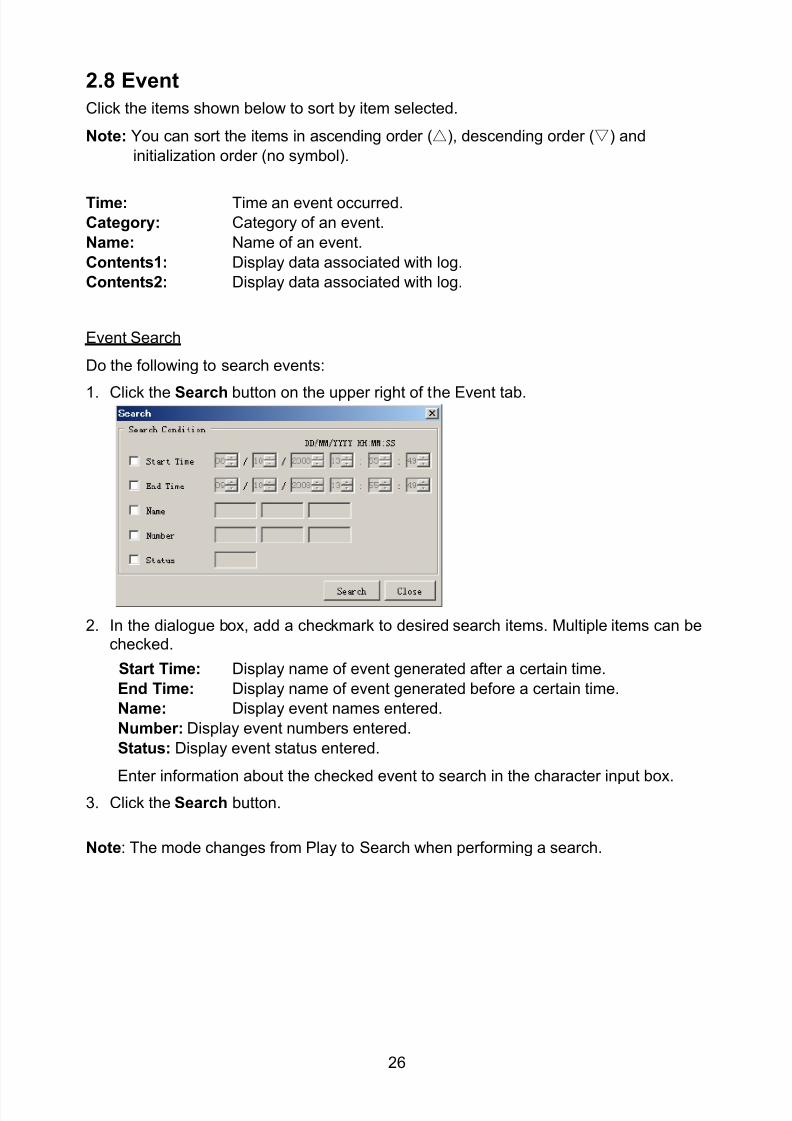
8102019 Ome44376d Vr3000 Mainte Cof26amp3bmol
httpslidepdfcomreaderfullome44376d-vr3000-mainte-cof26amp3bmol 2857
26
28 Event
Click the items shown below to sort by item selected
Note You can sort the items in ascending order () descending order () and
initialization order (no symbol)
Time Time an event occurred
Category Category of an event
Name Name of an event
Contents1 Display data associated with log
Contents2 Display data associated with log
Event Search
Do the following to search events
1 Click the Search button on the upper right of the Event tab
2 In the dialogue box add a checkmark to desired search items Multiple items can bechecked
Start Time Display name of event generated after a certain time
End Time Display name of event generated before a certain time
Name Display event names entered
Number Display event numbers entered
Status Display event status entered
Enter information about the checked event to search in the character input box
3 Click the Search button
Note The mode changes from Play to Search when performing a search
8102019 Ome44376d Vr3000 Mainte Cof26amp3bmol
httpslidepdfcomreaderfullome44376d-vr3000-mainte-cof26amp3bmol 2957
27
29 Hardware
The Hardware tab provides information about the system hardware
The buttons in the Setting window work as follows
Self Check Status Display status of self check
CPU Display information about the CPU
Memory Size Display memory size
CPU Board Display status of CPU board
Audio Board Display status of Audio board
Serial Board Display status of Serial board
Radar Interface Board Display status of Radar Interface boardNote Enter and display note
Marked items are optional
8102019 Ome44376d Vr3000 Mainte Cof26amp3bmol
httpslidepdfcomreaderfullome44376d-vr3000-mainte-cof26amp3bmol 3057
28
210 JB
Connect the Junction Box to the DCU before turning on the system
The JB tab functions to set up the Junction Box
The basic procedure for setting up the Junction Box is as follows
1 Click the JB tab2 Select a Junction Box from the Information Area
3 Set up the Junction Box from the Setting Area
4 Click the Set button (Be sure to do this before moving to another channel)5 Click the Check button to perform an inspection on all channels In the Information
Area check column either OK or NG (No Good) is displayed
When using Config Manager with Tabs
1 From the Maintenance menu click VDR Config Management
2 Click the Upload button to record to VDR memory
3 Click the Write buttons to record to DRU Backup HDD and CF
The items in the Setting window work as followsActive Put check in check box to make channel activeNo Display Junction Box numberIP Address Display IP address of Junction Box acquired by VDRMAC Address Display MAC address of Junction Box acquired by VDRCheck Enable and disable equipment checkNote Enter note
Marked items are optional
8102019 Ome44376d Vr3000 Mainte Cof26amp3bmol
httpslidepdfcomreaderfullome44376d-vr3000-mainte-cof26amp3bmol 3157
29
211 Life Time
The Life Time tab controls consumable parts
The basic procedure for using the Life Time tab is as follows
1 Click the Life Time tab
2 Select a Type No in the Information Area3 Set up the chosen part from Setting Area
4 Click the Set button
Note Be sure to click the Set button before moving to set up a different Type
The items in the Setting window work as follows
Type No Enter and display type no
Data Name Enter and display data name
Level Set replacement level Legal Exchange Parts or Normal Exchange Parts
Replace Date Enter and display recommended day of replacement
Lifetime Term Not usedNote Enter and display note
The Status column of the Information Area displays as follows
OK The recommended date of replacement shown in the Replace Date
box in the Information window has not passed
Out of Date The date of replacement has passed
None The date of replacement has not been set
8102019 Ome44376d Vr3000 Mainte Cof26amp3bmol
httpslidepdfcomreaderfullome44376d-vr3000-mainte-cof26amp3bmol 3257
30
212 Network
The Network tab sets the system network
The basic procedure for setting up the system network is as follows
1 Click the Network tab
2 Select a port from the Information Area
3 Set up the network from the Setting Area
4 Click the Set button
Note1 Be sure to click the Set button before moving to set up a different Port
Note2 After setting the system network reboot the VDR to apply the settings
The items in the Setting window work as follows
LAN Type Enter LAN type Public LAN or JB LAN
MAC Address Enter MAC address
IP Address Enter IP address
Subnet Mask Enter subnet mask
Gateway Address Enter gateway address
Live Play Multicast Mode (Only JB LAN) Check box to enable live player multicast
mode
Multicast Address (Only Public LAN) Enter and display live player multicast addressNote Enter note
Marked items are optional
8102019 Ome44376d Vr3000 Mainte Cof26amp3bmol
httpslidepdfcomreaderfullome44376d-vr3000-mainte-cof26amp3bmol 3357
31
213 System
The System tab sets system related functions
The basic procedure for using the System tab is as follows
1 Click the System tab
2 Set up the chosen item from the Setting Area
3 Click the Set button
Note Be sure to click the Set button before moving to a different tab
The items in the Setting window work as follows
VDR Type Enter type of VDR
VDR Model Enter model number of VDR
Radar Interface Check Enable and disable checking of the Radar Interface board
Junction Box Count Enter number of junction boxes in system
DRU Flash Count Enter number of DRU flash disks in system Set 1 when DRU
serial no is 5000 and more Set 3 when DRU serial no is less
than 5000
DRU Capacity Display capacity of DRU
Backup HDD Capacity Display capacity of Backup HDD
VDR Config Version Display version no of VDR
VDR Config Date Display the number of hours the VDR settings have
been saved
VDR Config Code Display configuration identity code
Installation Engineer Enter name of the equipment installer
Installation Company Enter name of installers company
8102019 Ome44376d Vr3000 Mainte Cof26amp3bmol
httpslidepdfcomreaderfullome44376d-vr3000-mainte-cof26amp3bmol 3457
32
Installation Date Enter the date of the installation
MIC Test Time Enter the date of the MIC test
Note Enter note Marked items are optional
USB memory logging Do not check Enable
IEEE1394 BUS Error Auto Restart function Not used
IEEE1394 Active Node Count Do not change the default value of 3 (However set to 5
for serial number 5000 or less of DRU)
IEEE1394 Recover Process Limit Count Do not change the default value of 10
DRU Error Auto Restart function Not used
REBOOT DELAY TIME (sec) Do not change the default value of 10
LIMIT REBOOT COUNT Do not change the default value of 10
Live Player Max Connection Count The max number of Live Player V4 that can be
connected simultaneously The default no is two
but a maximum of five can be set here After you
change this option reboot the VDR to apply the
setting Disconnect the cable connected with
Live Player V4 (PC) from the VDR and thenreconnect it
214 Software
The Software tab sets and display software-related operations
The basic procedure for using the Software tab is as follows
1 Click the Software tab
2 Set up the chosen Item from the Setting Area
3 Click the Set button
8102019 Ome44376d Vr3000 Mainte Cof26amp3bmol
httpslidepdfcomreaderfullome44376d-vr3000-mainte-cof26amp3bmol 3557
33
The items in the Setting window work as follows
VDR System Program Display the VDR system program no
Process Version Display the process version
Power Distribution Unit (PDU) Display the version no of the PDU
Operation System Display the version no of the OS
Audio Driver Display the version no of the audio driverRAP Version Enter the version no of the RAP
AP Version Enter the version no of the AP
JB1-8 Boot Program Display the no of the RJB Boot program for Junction Boxes
1 to 8
JB1-8 App Program Display the no of the RJB App program for Junction Boxes
1 to 8
Watch Dog Interval Do not change the default value of 60 (Enter the process
response time A process is repeated if there is no response
within the time interval set here)
Giveup Interval Do not change the default value of 300 (Enter the restart
watch time The restarting of a process is stopped when the
number of times it has been restarted is exceeded within the
interval set here)
Refork Limit Do not change the default value of 10 (Enter the upper limit
for process restart The restarting of a process is stopped
when the number of times it has been restarted exceeds the
Give up Interval)
Note Enter note
Marked Items are optional
8102019 Ome44376d Vr3000 Mainte Cof26amp3bmol
httpslidepdfcomreaderfullome44376d-vr3000-mainte-cof26amp3bmol 3657
34
215 GPS
The GPS tab sets GPS-related parameters
The basic procedure for using the GPS tab is as follows
1 Click the GPS tab
2 Set up the chosen channel from the Information window3 Set up the chosen item in the Setting Area
4 Click the Set button
5 Repeat steps 2-4 to set up each Channel
6 Click the Check button to perform an inspection on all channels In the Information Area check column either OK or NG (No Good) is displayed
The items in the Setting window work as follows
Priority Display priority order
Date and Time SourceShip Position Source Set GPS source channel (serial channel
number for ZDA sentence)
Check Enable and disable checking
GPS Antenna Position From Bow Enter position of GPS antenna from bow
GPS Antenna Position From Stern Enter position of GPS antenna from stern
GPS Antenna Position From Port Enter position of GPS antenna from port
GPS Antenna Position From Starboard Enter position of GPS antenna from starboard
GPS Failure Threshold If the ZDA is input within the set time limit
the system restarts synchronized If not
input within the time limit the system restarts
without synchronization
8102019 Ome44376d Vr3000 Mainte Cof26amp3bmol
httpslidepdfcomreaderfullome44376d-vr3000-mainte-cof26amp3bmol 3757
35
GPS Delay Time by Time Sync Enter minimum time delay for time
synchronization Time synchronization is started
only in the time set here
GPS Difference Interval The time set here is added to the GPS time to
synchronize the system time Leave at the default
0 value setting
GPS Sync Giveup Time If the system receives the GPS time within the
time set the system synchronizes with the time
When not receiving a signal the system displays
an ldquoerror 26rdquo message
ZDA Timeout Enter value (seconds) for ZDA timeout (234 error)
from GPS
Note Enter and display note
Marked Items are optional
216 VesselThe Vessel tab sets and displays own ships information such as name and IMO number
The basic procedure for using the Vessel tab is as follows
1 Click the Vessel tab
2 Set up information in the Setting window
3 Click the Set button (Be sure to do this before moving to another port)
4 From the Maintenance menu click VDR Config Management and then Config5 Click the Write buttons to save data to the DRU backup HDD CF
The buttons in the Setting window works as follows
Vessel Name Enter name of vessel
Vessel IMO Number Enter IMO number of vessel
Vessel Flag Enter flag of vessel
Approval of Authority Enter name of approving authority
Note Enter note
Marked items are optional
8102019 Ome44376d Vr3000 Mainte Cof26amp3bmol
httpslidepdfcomreaderfullome44376d-vr3000-mainte-cof26amp3bmol 3857
36
217 Delivery
The Delivery tab functions to transmit data from the VDR to a PC via Ethernet LAN Do
not use this function during live connection
The basic procedure for using the Delivery tab is as follows
1 Click the Delivery tab
2 Click the Add button to show the Delivery Config window
3 Select protocol from the Protocol drop-down box (Unicast or Multicast)
4 Enter IP address in the IP address input box
5 Enter port number in the port number input box
6 Click the tab of the data to send (Analog Digital or Serial)
7 Select the channel of the data to send
8 If Serial was selected at step 6 select applicable data sentence from the Inactivewindow Click the right arrow to move the data sentence to the Active window
9 Click the OK button to close the Delivery Config window
10 The settings are listed in a table in the Delivery window Check the checkbox in the
Active column and then click the Set button
The buttons in the Setting window works as follows
Set Save edited settings
Add Create new delivery settings
Modify Modify selected delivery settings
Delete Delete selected delivery settings
8102019 Ome44376d Vr3000 Mainte Cof26amp3bmol
httpslidepdfcomreaderfullome44376d-vr3000-mainte-cof26amp3bmol 3957
37
3 How to Back up Configuration DataThis chapter shows how to back up configuration data to various storage media
Configuration data can be opened with Word Pad or any text editor other than Notepad
31 How to Back up Configuration Data to the Startup CompactFlash (CF)
Back up data to the startup CF after setting the VDR Configuration data is created on the
CF as a configini file
Note When the error shown below occurs during the downloading or uploading of
configuration data check the connection of the DRU Backup HDD and CF and then
upload or download the configuration data again
[CONN] Download failed
[CONN] Could not upload config file
If error occurs again re-install the VDR Maintenance Viewer
Do the following to back up data to a CF
1 Set up parameters on the tabs referring to Chapter 2
2 Click the Maintenance menu
3 Select VDR Config Management
4 Click the Upload button
5 A confirmation box appears click the OK button to start uploading to the VDR
6 Click the Write button where the arrow connects between VDR and DRU BackupHDD
7 A confirmation window appears click the OK button to save the configuration data tothe DRU and Backup HDD
8102019 Ome44376d Vr3000 Mainte Cof26amp3bmol
httpslidepdfcomreaderfullome44376d-vr3000-mainte-cof26amp3bmol 4057
38
8 Click the Write button where the arrow connects between the VDR and CF
9 A confirmation window appears click the OK button to save the configuration data tothe startup CF
10 Check that the PC VDR DRU Backup HDD and CF share the same VDR configcode
32 How to Back up Configuration Data to a PC
Configuration data saved to the PC can be edited with Wordpad and shared with other
vessels For future service ease it is recommended to backup configuration data to the
PC and have the data on board the vessel Also it is recommended to upload this data to
Furuno SMS (Service Management System) If unable to upload to Furuno SMS please
contact the Service Center Furuno Japan
To back up configuration data to the PC do as follows
1 Set up parameters on the tabs referring to Chapter 2
2 Click the Maintenance menu
3 Select VDR Config Management
4 Click the Export to button
5 A confirmation window appears click the OK button
6 Select where to save the data enter file name then click the Open button
7 Confirm that back up file is in the location selected
33 How to restore the default settings
Click the Default button on the VDR Config Management window to restore the default
settings of the DRU Backup HDD CF and VDR Maintenance Viewer
8102019 Ome44376d Vr3000 Mainte Cof26amp3bmol
httpslidepdfcomreaderfullome44376d-vr3000-mainte-cof26amp3bmol 4157
39
4 How to Upload Configuration Datafrom a PCThe procedure below shows how to upload configuration from the PC to aVR-3000VR-3000S
1 Click the Maintenance menu
2 Select VDR Config Management
3 Click the Import from button
4 The Open window appears Select configuration data and then click the Open button
5 Click the Upload button to upload data to the VR-3000VR-3000S
6 Click the Write buttons to save data to the DRU backup HDD and CF
8102019 Ome44376d Vr3000 Mainte Cof26amp3bmol
httpslidepdfcomreaderfullome44376d-vr3000-mainte-cof26amp3bmol 4257
40
5 Media ManagementThe media management feature deletes data from recording media initialization the
system etc There are two method LAN connection and Direct connection The Direct
connection takes longer time than the LAN connection Basically use the LAN connection
method
Note Initialization or creation of recording media is not available when Source Select onthe Live Player V4 is selected to Backup HDD
51 Initialization
This section shows how to delete data from the recording media Configuration data is
not deleted After performing the software configuration delete the data from the DRU
and HDD
Do the following to delete data from the DRU (LAN connection)
1 Set the PlaybackCPU switch in the DCU to the CPU position
2 Use an Ethernet cross cable to connect the PC to J14 (DATA) in the DCU (See page5)
3 Open the Tool menu
4 Select Media Management to open the VDR Media Management window
5 Check that IP address shown in the ldquoLAN Connect to IPrdquo in VDR Media Table Area isthe same as the IP address access point
6 Select ldquoLAN Connect to IPrdquo in the VDR Media Table column
8102019 Ome44376d Vr3000 Mainte Cof26amp3bmol
httpslidepdfcomreaderfullome44376d-vr3000-mainte-cof26amp3bmol 4357
41
7 Click the Analyze button A list of recording media connected to the VDR appears
Put a checkmark in the checkbox of the Select column for the DRU in the Name columnNote If there are several flash memories in the DRU all flash memories are shownCheck all flash memories shown
8 Select ldquoDRU Initializerdquo from the Operation dropdown list in the Operation area
10 Click the Run button
Do the following to delete data from the DRU (Direct connection)
1 Start Live Player V4 software
2 Open the Tool menu and select Source Select Select Live from the pull-downmenu
3 Click the Alarm tab and open Alarm History
4 Set the PlaybackCPU switch in the DCU to the Playback position
5 Wait approx 10 minutes and confirm that Alarm 174 occurs on Alarm History of LivePlayer V4
6 Connect an IEEEE1394 cable between J6 in the DCU and the PC
7 Open the Tool menu
8 Select Media Management to show the VDR Media Management window
9 Select Direct in the VDR Media Table column
10 Click the Analyze button A list of recording media connected to the VDR appears
11 Put a checkmark in the checkbox of the Select column for the DRU in the Namecolumn
Note If there are several flash memories in the DRU all flash memories are shownCheck all flash memories shown
12 Select ldquoDRU Initializerdquo from the Operation dropdown list in the Operation area
13 Enter password in the password column
14 Click the RUN button
8102019 Ome44376d Vr3000 Mainte Cof26amp3bmol
httpslidepdfcomreaderfullome44376d-vr3000-mainte-cof26amp3bmol 4457
42
Delete data from the Backup HDD as follows (LAN connection)
1 Set the PlaybackCPU switch in the DCU to the CPU position
2 Check that an Ethernet cross cable is connected between J14 in the DCU and the PC
3 Open the Tool menu
4 Select Media Management to open the VDR Media Management window
5 Check that IP address shown in the LAN Connect to IP in VDR Media Table Area is
the same as the IP address access point6 Select LAN Connect to IP in the VDR Media Table column
7 Click the Analyze button
8 A list of recording media connected to the VDR appears
9 Put a checkmark in the box of the Select column for the Backup HDD in the Namecolumn Select ldquoBackup HDD Initializerdquo from the Operation dropdown list in theOperation area
10 Click the Run button
Delete data from the Backup HDD as follows (Direct connection)
1 Start Live Player V4 software
2 Open the Tool menu and select Source Select Select Live from the pull-downmenu
3 Click the Alarm tab and open Alarm History
4 Set the PlaybackCPU switch in the DCU to the Playback position
5 Wait approx 10 minutes and confirm that Alarm 174 occurs on Alarm History of LivePlayer V4
6 Connect an IEEE1394 cable between J6 in the DCU and the PC
7 Open the Tool menu
8 Select Media Management to open the VDR Media Management window9 Select Direct in the VDR Media Table window
10 Click the Analyze button A list of recording media connected to the VDR appears
11 Put a checkmark in the check box of the Select column for the Backup HDD in theName column Select ldquoBackup HDD Initializerdquo from the Operation dropdown list in theOperation area
12 Enter password
13 Click the Run button
8102019 Ome44376d Vr3000 Mainte Cof26amp3bmol
httpslidepdfcomreaderfullome44376d-vr3000-mainte-cof26amp3bmol 4557
43
52 CreationThe Creation feature initializes recording media
Note1 This feature deletes ALL configuration data Backup all VDR configuration data
Note2 When you initialize medium that is a different format for the DRU or Backup HDDdelete all partitions with the disk management tool of Windows
Note3 When the Creation is failed try again If you can not initialize recording media tryunder condition as shown below
Do the Creation by the direct connection (When the Creation by the LAN
connection is failed)
Delete all partitions of the DRU or Backup HDD with the disk management tool of
Windows to do the Creation
If the Creation is still failed request service to repairreplace the DRU or Backup
HDD
Initialize the DRU as follows (LAN connection)
1 Set the PlaybackCPU switch in the DCU to the CPU position
2 Check that an Ethernet cross cable is connected between J14 in the DCU and the PC
3 Open the Tool menu
4 Select Media Management to open the VDR Media Management window
5 Check that IP address shown in the LAN Connect to IP in VDR Media Table Area isthe same as the IP address access point
6 Check ldquoLAN Connect to IPrdquo in the VDR Media Table column
7 Click the Analyze button A list of recording media connected to the VDR appears
8 Put a checkmark in the box of the Select column for the DRU in the Name column
Select ldquoDRU Creationrdquo from the Operation dropdown list in the Operation area
9 Click the Run button
Initialize the Backup HDD as follows (LAN connection)
1 To format the Backup HDD place a checkmark in the Select column of the listedrecord media in the Name column of the VDR Media Management dialogue box
2 From the Operation drop down list of the Operation area select ldquoBackup HDDCreation (Radar) or ldquoBackup HDD Creationrdquo
Two partition tools are available for the Backup HDD in the Media Management as
below
Backup HDD creation
This tool is used when the number of the SXGA video signal connected to the BackupHDD is the same as the DRU The same partition is created on both DRU and HDD
(1) When two SXGA video signals are recorded onto the HDD while 9-GB DRU isconnected
(2) When an SXGA video signal is recorded onto the HDD while 6-GB DRU isconnected
Backup HDD creation (radar)
This tool is used when two SXGA video signals are recorded onto the HDD with 6-GB
DRU connected The HDD has an area (radar) to record the second radar signal inaddition to the same partition as the DRU This tool cannot be used when 9-GB DRUis connected
3 Press the Run Button
8102019 Ome44376d Vr3000 Mainte Cof26amp3bmol
httpslidepdfcomreaderfullome44376d-vr3000-mainte-cof26amp3bmol 4657
44
Initialize the DRU as follows (Direct connection)
1 Start Live Player V4 software
2 Open the Tool menu and select Source Select Select Live from the pull-downmenu
3 Click the Alarm tab and open Alarm History
4 Set the PlaybackCPU switch in the DCU to the Playback position
5 Wait approx 10 minutes and confirm that Alarm 174 occurs on Alarm History of LivePlayer V4
6 Connect an IEEE1394 cable between J6 in the DCU and the PC
7 Open the Tool menu
8 Select Media Management to open the VDR Media Management window
9 Select Direct in the VDR Media Table window
10 Click the Analyze button A list of recording media connected to the VDR appears
11 Put a checkmark in the box of the Select column for the DRU and the desiredrecording media in the Name column In the Operation dropdown list of the Operationarea select ldquoDRU Creationrdquo
12 Enter password in the password column
13 Click the Run button
Initialize the Backup HDD as follows (Direct Connection)
1 To format the Backup HDD place a checkmark in the Select column of the listedrecord media in the Name column of the VDR Media Management dialogue box
2 From the Operation column of the Operation area select ldquoBackup HDD Creation(Radar) or ldquoBackup HDD Creationrdquo
Backup HDD creation
This tool is used when the number of the SXGA video signal connected to the BackupHDD is the same as the DRU The same partition is created on both DRU and HDD
(1) When two SXGA video signals are recorded onto the HDD while 9-GB DRU is
connected
(2) When an SXGA video signal is recorded onto the HDD while 6-GB DRU is
connected
Backup HDD creation (radar)
This tool is used when two SXGA video signals are recorded onto the HDD with 6-GBDRU connected The HDD has an area (radar) to record the second radar signal inaddition to the same partition as the DRU This tool cannot be used when 9-GB DRUis connected
3 Enter the password in the Password column
4 Press the Run Button
8102019 Ome44376d Vr3000 Mainte Cof26amp3bmol
httpslidepdfcomreaderfullome44376d-vr3000-mainte-cof26amp3bmol 4757
45
53 How to Enable Recording Area on the Backup HDD
This function enables writing over a recording area To prevent falsification of data all
recording areas must be saved otherwise this function is disabled To use this function push
the SAVE button Save the data before doing this procedure
Note Software version 135 or higher can enable writing over a recording area even if
all recording areas are not saved
Recording enable (LAN connection)
1 Set the PlaybackCPU switch in the DCU to the CPU position
2 Check that an Ethernet cross cable is connected between J14 in the DCU and the PC
3 Open the Tool menu
4 Select Media Management to open the VDR Media Management window
5 Check that IP address shown in the ldquoLAN Connect to IPrdquo in VDR Media Table Area isthe same as the IP address access point
6 Select ldquoLAN Connect to IPrdquo in the VDR Media Table column7 Click the Analyze button A list of recording media connected to the VDR appears
8 Put a checkmark in the box of the Select column for the Backup HDD in the Namecolumn
9 Select ldquoBackup HDD Recording Area Enablerdquo from the Operation dropdown list in theOperation area
10 Click the Run button
Recording enable (Direct connection)
1 Start Live Player V4 software
2 Open the Tool menu and select Source Select Select Live from the pull-down menu3 Click the Alarm tab and open Alarm History
4 Set the PlaybackCPU switch in the DCU to the Playback position
5 Wait approx 10 minutes and confirm that Alarm 174 occurs on Alarm History of LivePlayer V4
6 Connect an IEEE1394 cable between J6 in the DCU and the PC
7 Open the Tool menu
8 Select Media Management to open the VDR Media Management window
9 Select Direct in the VDR Media Table window
10 Click the Analyze button A list of recording media connected to the VDR appears11 Put a checkmark in the box of the Select column for the Backup HDD in the Name
column
12 Select ldquoBackup HDD Recording Area Enablerdquo from the Operation dropdown list in theOperation area
13 Enter password
14 Click the Run button
8102019 Ome44376d Vr3000 Mainte Cof26amp3bmol
httpslidepdfcomreaderfullome44376d-vr3000-mainte-cof26amp3bmol 4857
46
6 Other Functions
61 Software Management
The software download feature downloads VDR system software to the PC
To download software
1 Click the Maintenance menu
2 From the Software Management menu click Software Download to show theSoftware Download window
3 Enter the IP address 1000100 in the IP address box in the Update Server area
4 Click the Download Software button
5 The confirmation window appears click the OK button
The Software Backup Execute window shows the results of the download
Software is downloaded to C Program Files VDR Viewer Viewer Backup The software file
name is vdrtar
To Update Software
VDR system program version 16x can update the software with the procedure shownbelow
Note Do not update the file downloaded in procedures above
1 Click the Maintenance menu
2 From the Software Management menu click Software Upload to show the SoftwareUpload area
3 Click the Select button to show the Open window
4 Select update file (vdrtar) and click the Open button
8102019 Ome44376d Vr3000 Mainte Cof26amp3bmol
httpslidepdfcomreaderfullome44376d-vr3000-mainte-cof26amp3bmol 4957
47
5 Check the displayed Software information is correct
6 Enter the IP address 1000100 in the IP address box in the Update Server area
7 Enter password
8 Click the Update button
After the updating is completed the VDR is automatically restarted
Note Click the Restore button on the Software Update window to restore previoussoftware version This feature is available after updating the software
62 Password Management
The password can be changed for a serviceman to access the equipment Contact
FURUNO to get the default password to use during installation
Serviceman password
1 Click the Maintenance menu2 Select Change Serviceman Password from Password Management to show the
Change Serviceman Password window
3 Enter current password in the Old Password box
4 Enter the new password in the New Password box of the Change Password area
5 Enter new password again in the Confirm New Password box
6 Click the OK button
Audio password
The audio password set at the VDR Maintenance Viewer can be removed to enable
audio access without password1 Click the Maintenance menu
2 Select Change Audio Password from Password Management to show the Change Audio Password window
3 The confirmation window appears click the OK button
8102019 Ome44376d Vr3000 Mainte Cof26amp3bmol
httpslidepdfcomreaderfullome44376d-vr3000-mainte-cof26amp3bmol 5057
48
63 Record ComparisonThe integrity of the DRU and Backup HDD recordings can be compared This function isused by the RampD engineer for debugging
Follow the procedure as shown below
1 Click the Maintenance menu2 Select Record Comparison to show the Record Comparison window
The results are shown every 15 seconds in the Record Comparison window
8102019 Ome44376d Vr3000 Mainte Cof26amp3bmol
httpslidepdfcomreaderfullome44376d-vr3000-mainte-cof26amp3bmol 5157
49
64 Software History
This section shows you to save and configure software history (communications record)
How to save software history
Note When the error dialog appears while saving the software history restart the VDR
Maintenance Viewer
1 Click the Maintenance menu
2 Select Software History Collect
3 Click the Select button The Open dialog box appears
4 Select where to save the data then click the Open button
5 Select desired save condition then click the OK buttonNone No savingAt Once Save the software history manually Saving begins as soon as the OK button is clickedPeriodic For debugging Do not use otherwise The intervals are 30 sec 60 secand 120 secAlarm Detection For debugging Do not use otherwise Software history is savedwhen specified alarm is released Enter alarm number
How to configure software communications record
The RampD engineer uses this function for debugging Do not do this procedure unless
required Malfunction can result
1 Click the Maintenance menu
2 Select Software History Config
3 Do the followingProcess Select the type of communications record to save ALL saves allcommunications records
Detail Hide or show detailed information4 Click the Send button
8102019 Ome44376d Vr3000 Mainte Cof26amp3bmol
httpslidepdfcomreaderfullome44376d-vr3000-mainte-cof26amp3bmol 5257
50
65 Easy SetupThis feature sets equipment settings in batch and creates a data file of those settings
Default template The default template is created with the settings entered at installation
1 Click the Maintenance menu
2 Select Easy Setup to show the Template Selection window
3 Select Default Template
4 Click the Start button to show the Easy Setup window
5 Right click the channels (Radar Audio Digital Serial Analog) then select Edit toshow the Equipment Selection window
6 From the Equipment Directory window select equipment connected to the selectedchannel and then click the OK button
7 Repeat steps 5 and 6 to select equipment settings for each channel
8 Click the Save button in the Easy Setup window to show the Save window
9 Select where to save the file and enter file name
10 Click the Save button
8102019 Ome44376d Vr3000 Mainte Cof26amp3bmol
httpslidepdfcomreaderfullome44376d-vr3000-mainte-cof26amp3bmol 5357
51
Specific template Use a file already created
1 Click the Maintenance menu
2 Select Easy Setup to show the Template Selection window
3 Check Specified Template
4 Click the Select button and then select the file to edit
5 Click the Start button to show the Easy Setup window
6 Right click the channels (Radar Audio Digital Serial Analog) then select Edit toshow the Equipment Selection window
7 From the Equipment Directory window select equipment connected to the selectedchannel and then click the OK button
8 Repeat steps 6 and 7 to select equipment settings for each channel
9 Click the Save button in the Easy Setup window to show the Save window
10Select where to save the file and enter file name
11 Click the Save button
66 Equipment Management
This feature controls the import and export of equipment settings
Import data file
Import data files of equipment settings created in Easy Setup etc to the VDR
1 Click the Maintenance menu
2 Select Import from Equipment Management to show the Open window
3 Select the data file to import and click Open
Export data file
Export data files of equipment settings from the VDR to a PC
1 Click the Maintenance menu
2 Select Export from Equipment Management to show the Save window
3 Enter file name
4 Click the Save button
8102019 Ome44376d Vr3000 Mainte Cof26amp3bmol
httpslidepdfcomreaderfullome44376d-vr3000-mainte-cof26amp3bmol 5457
52
67 PC_RAP
This feature enables the same operation of the RAP (Remote Alarm Panel) from a PC
Select PC_RAP from the Tool menu to show the PC_RAP window
The buttons in the PC_RAP window function as shown below
SAVE Stop recording in the area where recording is currently being done
ACK Silence audio alarm
The PC_RAP display shows the following information with LEDs
RAP_LEDs Display the status of LEDs on the RAPSave The Save button blinks yellow when pushed When the 4 memory
areas have data recorded to them the Save button lights orange when
pushed
Normal Lights (green) where there are no unconfirmed or not restored
alarms
Error Flashes (red) for not confirmed alarm Lights (red) for unrestored
alarm
8102019 Ome44376d Vr3000 Mainte Cof26amp3bmol
httpslidepdfcomreaderfullome44376d-vr3000-mainte-cof26amp3bmol 5557
53
Backup HDD Information Display status of backup HDD
Selected Display current recording area and its status in green for
normal operation and in red for abnormal operation
Size Display capacity of backup HDD
Alarm area displays unconfirmed alarms
Time Display time alarm was generatedNumber Display number of alarm
Name Display name of alarm
Pending Alarm displays the unrestored alarms out of confirmed alarms only
Time Display time alarm was generated
Number Display number of alarm
Name Display name of alarm
8102019 Ome44376d Vr3000 Mainte Cof26amp3bmol
httpslidepdfcomreaderfullome44376d-vr3000-mainte-cof26amp3bmol 5657
54
68 Other
Status Monitor
The status monitor feature provides comprehensive data about the status of the VDR
From the menu bar click Toolgt Status Monitor to show the Status Monitor window
The buttons in the Status Monitor window work as shown below
Reload Settings for automatic refreshing of the status monitor
ON Turn automatic refresh OFF
OFF The Status Monitor is refreshed every five seconds
Save Available when Reload ON is selected The contents of the Status Monitor can be
saved to a text fileUpdate Update the Status Monitor display
Close Close the Status Monitor display
8102019 Ome44376d Vr3000 Mainte Cof26amp3bmol
httpslidepdfcomreaderfullome44376d-vr3000-mainte-cof26amp3bmol 5757
VDR Error List
This feature compiles all the errors shown on the RAP for easy reference
Access from MenugtToolgtVDR Error List
The VDR error list contains the following information
NO Display the number of the error
Title Display the name of the error
Detail Display details about the error
Exchange Check
This feature removes the alarms generated when replacing the DRU or backup HDD
Access MenugtToolgtExchange Check select either DRU or Backup HDD and click OK
Reboot
Reboot the VDR
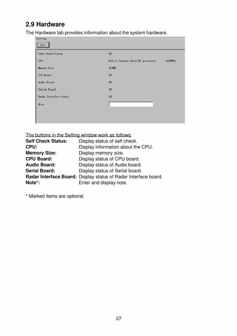
8102019 Ome44376d Vr3000 Mainte Cof26amp3bmol
httpslidepdfcomreaderfullome44376d-vr3000-mainte-cof26amp3bmol 2957
27
29 Hardware
The Hardware tab provides information about the system hardware
The buttons in the Setting window work as follows
Self Check Status Display status of self check
CPU Display information about the CPU
Memory Size Display memory size
CPU Board Display status of CPU board
Audio Board Display status of Audio board
Serial Board Display status of Serial board
Radar Interface Board Display status of Radar Interface boardNote Enter and display note
Marked items are optional
8102019 Ome44376d Vr3000 Mainte Cof26amp3bmol
httpslidepdfcomreaderfullome44376d-vr3000-mainte-cof26amp3bmol 3057
28
210 JB
Connect the Junction Box to the DCU before turning on the system
The JB tab functions to set up the Junction Box
The basic procedure for setting up the Junction Box is as follows
1 Click the JB tab2 Select a Junction Box from the Information Area
3 Set up the Junction Box from the Setting Area
4 Click the Set button (Be sure to do this before moving to another channel)5 Click the Check button to perform an inspection on all channels In the Information
Area check column either OK or NG (No Good) is displayed
When using Config Manager with Tabs
1 From the Maintenance menu click VDR Config Management
2 Click the Upload button to record to VDR memory
3 Click the Write buttons to record to DRU Backup HDD and CF
The items in the Setting window work as followsActive Put check in check box to make channel activeNo Display Junction Box numberIP Address Display IP address of Junction Box acquired by VDRMAC Address Display MAC address of Junction Box acquired by VDRCheck Enable and disable equipment checkNote Enter note
Marked items are optional
8102019 Ome44376d Vr3000 Mainte Cof26amp3bmol
httpslidepdfcomreaderfullome44376d-vr3000-mainte-cof26amp3bmol 3157
29
211 Life Time
The Life Time tab controls consumable parts
The basic procedure for using the Life Time tab is as follows
1 Click the Life Time tab
2 Select a Type No in the Information Area3 Set up the chosen part from Setting Area
4 Click the Set button
Note Be sure to click the Set button before moving to set up a different Type
The items in the Setting window work as follows
Type No Enter and display type no
Data Name Enter and display data name
Level Set replacement level Legal Exchange Parts or Normal Exchange Parts
Replace Date Enter and display recommended day of replacement
Lifetime Term Not usedNote Enter and display note
The Status column of the Information Area displays as follows
OK The recommended date of replacement shown in the Replace Date
box in the Information window has not passed
Out of Date The date of replacement has passed
None The date of replacement has not been set
8102019 Ome44376d Vr3000 Mainte Cof26amp3bmol
httpslidepdfcomreaderfullome44376d-vr3000-mainte-cof26amp3bmol 3257
30
212 Network
The Network tab sets the system network
The basic procedure for setting up the system network is as follows
1 Click the Network tab
2 Select a port from the Information Area
3 Set up the network from the Setting Area
4 Click the Set button
Note1 Be sure to click the Set button before moving to set up a different Port
Note2 After setting the system network reboot the VDR to apply the settings
The items in the Setting window work as follows
LAN Type Enter LAN type Public LAN or JB LAN
MAC Address Enter MAC address
IP Address Enter IP address
Subnet Mask Enter subnet mask
Gateway Address Enter gateway address
Live Play Multicast Mode (Only JB LAN) Check box to enable live player multicast
mode
Multicast Address (Only Public LAN) Enter and display live player multicast addressNote Enter note
Marked items are optional
8102019 Ome44376d Vr3000 Mainte Cof26amp3bmol
httpslidepdfcomreaderfullome44376d-vr3000-mainte-cof26amp3bmol 3357
31
213 System
The System tab sets system related functions
The basic procedure for using the System tab is as follows
1 Click the System tab
2 Set up the chosen item from the Setting Area
3 Click the Set button
Note Be sure to click the Set button before moving to a different tab
The items in the Setting window work as follows
VDR Type Enter type of VDR
VDR Model Enter model number of VDR
Radar Interface Check Enable and disable checking of the Radar Interface board
Junction Box Count Enter number of junction boxes in system
DRU Flash Count Enter number of DRU flash disks in system Set 1 when DRU
serial no is 5000 and more Set 3 when DRU serial no is less
than 5000
DRU Capacity Display capacity of DRU
Backup HDD Capacity Display capacity of Backup HDD
VDR Config Version Display version no of VDR
VDR Config Date Display the number of hours the VDR settings have
been saved
VDR Config Code Display configuration identity code
Installation Engineer Enter name of the equipment installer
Installation Company Enter name of installers company
8102019 Ome44376d Vr3000 Mainte Cof26amp3bmol
httpslidepdfcomreaderfullome44376d-vr3000-mainte-cof26amp3bmol 3457
32
Installation Date Enter the date of the installation
MIC Test Time Enter the date of the MIC test
Note Enter note Marked items are optional
USB memory logging Do not check Enable
IEEE1394 BUS Error Auto Restart function Not used
IEEE1394 Active Node Count Do not change the default value of 3 (However set to 5
for serial number 5000 or less of DRU)
IEEE1394 Recover Process Limit Count Do not change the default value of 10
DRU Error Auto Restart function Not used
REBOOT DELAY TIME (sec) Do not change the default value of 10
LIMIT REBOOT COUNT Do not change the default value of 10
Live Player Max Connection Count The max number of Live Player V4 that can be
connected simultaneously The default no is two
but a maximum of five can be set here After you
change this option reboot the VDR to apply the
setting Disconnect the cable connected with
Live Player V4 (PC) from the VDR and thenreconnect it
214 Software
The Software tab sets and display software-related operations
The basic procedure for using the Software tab is as follows
1 Click the Software tab
2 Set up the chosen Item from the Setting Area
3 Click the Set button
8102019 Ome44376d Vr3000 Mainte Cof26amp3bmol
httpslidepdfcomreaderfullome44376d-vr3000-mainte-cof26amp3bmol 3557
33
The items in the Setting window work as follows
VDR System Program Display the VDR system program no
Process Version Display the process version
Power Distribution Unit (PDU) Display the version no of the PDU
Operation System Display the version no of the OS
Audio Driver Display the version no of the audio driverRAP Version Enter the version no of the RAP
AP Version Enter the version no of the AP
JB1-8 Boot Program Display the no of the RJB Boot program for Junction Boxes
1 to 8
JB1-8 App Program Display the no of the RJB App program for Junction Boxes
1 to 8
Watch Dog Interval Do not change the default value of 60 (Enter the process
response time A process is repeated if there is no response
within the time interval set here)
Giveup Interval Do not change the default value of 300 (Enter the restart
watch time The restarting of a process is stopped when the
number of times it has been restarted is exceeded within the
interval set here)
Refork Limit Do not change the default value of 10 (Enter the upper limit
for process restart The restarting of a process is stopped
when the number of times it has been restarted exceeds the
Give up Interval)
Note Enter note
Marked Items are optional
8102019 Ome44376d Vr3000 Mainte Cof26amp3bmol
httpslidepdfcomreaderfullome44376d-vr3000-mainte-cof26amp3bmol 3657
34
215 GPS
The GPS tab sets GPS-related parameters
The basic procedure for using the GPS tab is as follows
1 Click the GPS tab
2 Set up the chosen channel from the Information window3 Set up the chosen item in the Setting Area
4 Click the Set button
5 Repeat steps 2-4 to set up each Channel
6 Click the Check button to perform an inspection on all channels In the Information Area check column either OK or NG (No Good) is displayed
The items in the Setting window work as follows
Priority Display priority order
Date and Time SourceShip Position Source Set GPS source channel (serial channel
number for ZDA sentence)
Check Enable and disable checking
GPS Antenna Position From Bow Enter position of GPS antenna from bow
GPS Antenna Position From Stern Enter position of GPS antenna from stern
GPS Antenna Position From Port Enter position of GPS antenna from port
GPS Antenna Position From Starboard Enter position of GPS antenna from starboard
GPS Failure Threshold If the ZDA is input within the set time limit
the system restarts synchronized If not
input within the time limit the system restarts
without synchronization
8102019 Ome44376d Vr3000 Mainte Cof26amp3bmol
httpslidepdfcomreaderfullome44376d-vr3000-mainte-cof26amp3bmol 3757
35
GPS Delay Time by Time Sync Enter minimum time delay for time
synchronization Time synchronization is started
only in the time set here
GPS Difference Interval The time set here is added to the GPS time to
synchronize the system time Leave at the default
0 value setting
GPS Sync Giveup Time If the system receives the GPS time within the
time set the system synchronizes with the time
When not receiving a signal the system displays
an ldquoerror 26rdquo message
ZDA Timeout Enter value (seconds) for ZDA timeout (234 error)
from GPS
Note Enter and display note
Marked Items are optional
216 VesselThe Vessel tab sets and displays own ships information such as name and IMO number
The basic procedure for using the Vessel tab is as follows
1 Click the Vessel tab
2 Set up information in the Setting window
3 Click the Set button (Be sure to do this before moving to another port)
4 From the Maintenance menu click VDR Config Management and then Config5 Click the Write buttons to save data to the DRU backup HDD CF
The buttons in the Setting window works as follows
Vessel Name Enter name of vessel
Vessel IMO Number Enter IMO number of vessel
Vessel Flag Enter flag of vessel
Approval of Authority Enter name of approving authority
Note Enter note
Marked items are optional
8102019 Ome44376d Vr3000 Mainte Cof26amp3bmol
httpslidepdfcomreaderfullome44376d-vr3000-mainte-cof26amp3bmol 3857
36
217 Delivery
The Delivery tab functions to transmit data from the VDR to a PC via Ethernet LAN Do
not use this function during live connection
The basic procedure for using the Delivery tab is as follows
1 Click the Delivery tab
2 Click the Add button to show the Delivery Config window
3 Select protocol from the Protocol drop-down box (Unicast or Multicast)
4 Enter IP address in the IP address input box
5 Enter port number in the port number input box
6 Click the tab of the data to send (Analog Digital or Serial)
7 Select the channel of the data to send
8 If Serial was selected at step 6 select applicable data sentence from the Inactivewindow Click the right arrow to move the data sentence to the Active window
9 Click the OK button to close the Delivery Config window
10 The settings are listed in a table in the Delivery window Check the checkbox in the
Active column and then click the Set button
The buttons in the Setting window works as follows
Set Save edited settings
Add Create new delivery settings
Modify Modify selected delivery settings
Delete Delete selected delivery settings
8102019 Ome44376d Vr3000 Mainte Cof26amp3bmol
httpslidepdfcomreaderfullome44376d-vr3000-mainte-cof26amp3bmol 3957
37
3 How to Back up Configuration DataThis chapter shows how to back up configuration data to various storage media
Configuration data can be opened with Word Pad or any text editor other than Notepad
31 How to Back up Configuration Data to the Startup CompactFlash (CF)
Back up data to the startup CF after setting the VDR Configuration data is created on the
CF as a configini file
Note When the error shown below occurs during the downloading or uploading of
configuration data check the connection of the DRU Backup HDD and CF and then
upload or download the configuration data again
[CONN] Download failed
[CONN] Could not upload config file
If error occurs again re-install the VDR Maintenance Viewer
Do the following to back up data to a CF
1 Set up parameters on the tabs referring to Chapter 2
2 Click the Maintenance menu
3 Select VDR Config Management
4 Click the Upload button
5 A confirmation box appears click the OK button to start uploading to the VDR
6 Click the Write button where the arrow connects between VDR and DRU BackupHDD
7 A confirmation window appears click the OK button to save the configuration data tothe DRU and Backup HDD
8102019 Ome44376d Vr3000 Mainte Cof26amp3bmol
httpslidepdfcomreaderfullome44376d-vr3000-mainte-cof26amp3bmol 4057
38
8 Click the Write button where the arrow connects between the VDR and CF
9 A confirmation window appears click the OK button to save the configuration data tothe startup CF
10 Check that the PC VDR DRU Backup HDD and CF share the same VDR configcode
32 How to Back up Configuration Data to a PC
Configuration data saved to the PC can be edited with Wordpad and shared with other
vessels For future service ease it is recommended to backup configuration data to the
PC and have the data on board the vessel Also it is recommended to upload this data to
Furuno SMS (Service Management System) If unable to upload to Furuno SMS please
contact the Service Center Furuno Japan
To back up configuration data to the PC do as follows
1 Set up parameters on the tabs referring to Chapter 2
2 Click the Maintenance menu
3 Select VDR Config Management
4 Click the Export to button
5 A confirmation window appears click the OK button
6 Select where to save the data enter file name then click the Open button
7 Confirm that back up file is in the location selected
33 How to restore the default settings
Click the Default button on the VDR Config Management window to restore the default
settings of the DRU Backup HDD CF and VDR Maintenance Viewer
8102019 Ome44376d Vr3000 Mainte Cof26amp3bmol
httpslidepdfcomreaderfullome44376d-vr3000-mainte-cof26amp3bmol 4157
39
4 How to Upload Configuration Datafrom a PCThe procedure below shows how to upload configuration from the PC to aVR-3000VR-3000S
1 Click the Maintenance menu
2 Select VDR Config Management
3 Click the Import from button
4 The Open window appears Select configuration data and then click the Open button
5 Click the Upload button to upload data to the VR-3000VR-3000S
6 Click the Write buttons to save data to the DRU backup HDD and CF
8102019 Ome44376d Vr3000 Mainte Cof26amp3bmol
httpslidepdfcomreaderfullome44376d-vr3000-mainte-cof26amp3bmol 4257
40
5 Media ManagementThe media management feature deletes data from recording media initialization the
system etc There are two method LAN connection and Direct connection The Direct
connection takes longer time than the LAN connection Basically use the LAN connection
method
Note Initialization or creation of recording media is not available when Source Select onthe Live Player V4 is selected to Backup HDD
51 Initialization
This section shows how to delete data from the recording media Configuration data is
not deleted After performing the software configuration delete the data from the DRU
and HDD
Do the following to delete data from the DRU (LAN connection)
1 Set the PlaybackCPU switch in the DCU to the CPU position
2 Use an Ethernet cross cable to connect the PC to J14 (DATA) in the DCU (See page5)
3 Open the Tool menu
4 Select Media Management to open the VDR Media Management window
5 Check that IP address shown in the ldquoLAN Connect to IPrdquo in VDR Media Table Area isthe same as the IP address access point
6 Select ldquoLAN Connect to IPrdquo in the VDR Media Table column
8102019 Ome44376d Vr3000 Mainte Cof26amp3bmol
httpslidepdfcomreaderfullome44376d-vr3000-mainte-cof26amp3bmol 4357
41
7 Click the Analyze button A list of recording media connected to the VDR appears
Put a checkmark in the checkbox of the Select column for the DRU in the Name columnNote If there are several flash memories in the DRU all flash memories are shownCheck all flash memories shown
8 Select ldquoDRU Initializerdquo from the Operation dropdown list in the Operation area
10 Click the Run button
Do the following to delete data from the DRU (Direct connection)
1 Start Live Player V4 software
2 Open the Tool menu and select Source Select Select Live from the pull-downmenu
3 Click the Alarm tab and open Alarm History
4 Set the PlaybackCPU switch in the DCU to the Playback position
5 Wait approx 10 minutes and confirm that Alarm 174 occurs on Alarm History of LivePlayer V4
6 Connect an IEEEE1394 cable between J6 in the DCU and the PC
7 Open the Tool menu
8 Select Media Management to show the VDR Media Management window
9 Select Direct in the VDR Media Table column
10 Click the Analyze button A list of recording media connected to the VDR appears
11 Put a checkmark in the checkbox of the Select column for the DRU in the Namecolumn
Note If there are several flash memories in the DRU all flash memories are shownCheck all flash memories shown
12 Select ldquoDRU Initializerdquo from the Operation dropdown list in the Operation area
13 Enter password in the password column
14 Click the RUN button
8102019 Ome44376d Vr3000 Mainte Cof26amp3bmol
httpslidepdfcomreaderfullome44376d-vr3000-mainte-cof26amp3bmol 4457
42
Delete data from the Backup HDD as follows (LAN connection)
1 Set the PlaybackCPU switch in the DCU to the CPU position
2 Check that an Ethernet cross cable is connected between J14 in the DCU and the PC
3 Open the Tool menu
4 Select Media Management to open the VDR Media Management window
5 Check that IP address shown in the LAN Connect to IP in VDR Media Table Area is
the same as the IP address access point6 Select LAN Connect to IP in the VDR Media Table column
7 Click the Analyze button
8 A list of recording media connected to the VDR appears
9 Put a checkmark in the box of the Select column for the Backup HDD in the Namecolumn Select ldquoBackup HDD Initializerdquo from the Operation dropdown list in theOperation area
10 Click the Run button
Delete data from the Backup HDD as follows (Direct connection)
1 Start Live Player V4 software
2 Open the Tool menu and select Source Select Select Live from the pull-downmenu
3 Click the Alarm tab and open Alarm History
4 Set the PlaybackCPU switch in the DCU to the Playback position
5 Wait approx 10 minutes and confirm that Alarm 174 occurs on Alarm History of LivePlayer V4
6 Connect an IEEE1394 cable between J6 in the DCU and the PC
7 Open the Tool menu
8 Select Media Management to open the VDR Media Management window9 Select Direct in the VDR Media Table window
10 Click the Analyze button A list of recording media connected to the VDR appears
11 Put a checkmark in the check box of the Select column for the Backup HDD in theName column Select ldquoBackup HDD Initializerdquo from the Operation dropdown list in theOperation area
12 Enter password
13 Click the Run button
8102019 Ome44376d Vr3000 Mainte Cof26amp3bmol
httpslidepdfcomreaderfullome44376d-vr3000-mainte-cof26amp3bmol 4557
43
52 CreationThe Creation feature initializes recording media
Note1 This feature deletes ALL configuration data Backup all VDR configuration data
Note2 When you initialize medium that is a different format for the DRU or Backup HDDdelete all partitions with the disk management tool of Windows
Note3 When the Creation is failed try again If you can not initialize recording media tryunder condition as shown below
Do the Creation by the direct connection (When the Creation by the LAN
connection is failed)
Delete all partitions of the DRU or Backup HDD with the disk management tool of
Windows to do the Creation
If the Creation is still failed request service to repairreplace the DRU or Backup
HDD
Initialize the DRU as follows (LAN connection)
1 Set the PlaybackCPU switch in the DCU to the CPU position
2 Check that an Ethernet cross cable is connected between J14 in the DCU and the PC
3 Open the Tool menu
4 Select Media Management to open the VDR Media Management window
5 Check that IP address shown in the LAN Connect to IP in VDR Media Table Area isthe same as the IP address access point
6 Check ldquoLAN Connect to IPrdquo in the VDR Media Table column
7 Click the Analyze button A list of recording media connected to the VDR appears
8 Put a checkmark in the box of the Select column for the DRU in the Name column
Select ldquoDRU Creationrdquo from the Operation dropdown list in the Operation area
9 Click the Run button
Initialize the Backup HDD as follows (LAN connection)
1 To format the Backup HDD place a checkmark in the Select column of the listedrecord media in the Name column of the VDR Media Management dialogue box
2 From the Operation drop down list of the Operation area select ldquoBackup HDDCreation (Radar) or ldquoBackup HDD Creationrdquo
Two partition tools are available for the Backup HDD in the Media Management as
below
Backup HDD creation
This tool is used when the number of the SXGA video signal connected to the BackupHDD is the same as the DRU The same partition is created on both DRU and HDD
(1) When two SXGA video signals are recorded onto the HDD while 9-GB DRU isconnected
(2) When an SXGA video signal is recorded onto the HDD while 6-GB DRU isconnected
Backup HDD creation (radar)
This tool is used when two SXGA video signals are recorded onto the HDD with 6-GB
DRU connected The HDD has an area (radar) to record the second radar signal inaddition to the same partition as the DRU This tool cannot be used when 9-GB DRUis connected
3 Press the Run Button
8102019 Ome44376d Vr3000 Mainte Cof26amp3bmol
httpslidepdfcomreaderfullome44376d-vr3000-mainte-cof26amp3bmol 4657
44
Initialize the DRU as follows (Direct connection)
1 Start Live Player V4 software
2 Open the Tool menu and select Source Select Select Live from the pull-downmenu
3 Click the Alarm tab and open Alarm History
4 Set the PlaybackCPU switch in the DCU to the Playback position
5 Wait approx 10 minutes and confirm that Alarm 174 occurs on Alarm History of LivePlayer V4
6 Connect an IEEE1394 cable between J6 in the DCU and the PC
7 Open the Tool menu
8 Select Media Management to open the VDR Media Management window
9 Select Direct in the VDR Media Table window
10 Click the Analyze button A list of recording media connected to the VDR appears
11 Put a checkmark in the box of the Select column for the DRU and the desiredrecording media in the Name column In the Operation dropdown list of the Operationarea select ldquoDRU Creationrdquo
12 Enter password in the password column
13 Click the Run button
Initialize the Backup HDD as follows (Direct Connection)
1 To format the Backup HDD place a checkmark in the Select column of the listedrecord media in the Name column of the VDR Media Management dialogue box
2 From the Operation column of the Operation area select ldquoBackup HDD Creation(Radar) or ldquoBackup HDD Creationrdquo
Backup HDD creation
This tool is used when the number of the SXGA video signal connected to the BackupHDD is the same as the DRU The same partition is created on both DRU and HDD
(1) When two SXGA video signals are recorded onto the HDD while 9-GB DRU is
connected
(2) When an SXGA video signal is recorded onto the HDD while 6-GB DRU is
connected
Backup HDD creation (radar)
This tool is used when two SXGA video signals are recorded onto the HDD with 6-GBDRU connected The HDD has an area (radar) to record the second radar signal inaddition to the same partition as the DRU This tool cannot be used when 9-GB DRUis connected
3 Enter the password in the Password column
4 Press the Run Button
8102019 Ome44376d Vr3000 Mainte Cof26amp3bmol
httpslidepdfcomreaderfullome44376d-vr3000-mainte-cof26amp3bmol 4757
45
53 How to Enable Recording Area on the Backup HDD
This function enables writing over a recording area To prevent falsification of data all
recording areas must be saved otherwise this function is disabled To use this function push
the SAVE button Save the data before doing this procedure
Note Software version 135 or higher can enable writing over a recording area even if
all recording areas are not saved
Recording enable (LAN connection)
1 Set the PlaybackCPU switch in the DCU to the CPU position
2 Check that an Ethernet cross cable is connected between J14 in the DCU and the PC
3 Open the Tool menu
4 Select Media Management to open the VDR Media Management window
5 Check that IP address shown in the ldquoLAN Connect to IPrdquo in VDR Media Table Area isthe same as the IP address access point
6 Select ldquoLAN Connect to IPrdquo in the VDR Media Table column7 Click the Analyze button A list of recording media connected to the VDR appears
8 Put a checkmark in the box of the Select column for the Backup HDD in the Namecolumn
9 Select ldquoBackup HDD Recording Area Enablerdquo from the Operation dropdown list in theOperation area
10 Click the Run button
Recording enable (Direct connection)
1 Start Live Player V4 software
2 Open the Tool menu and select Source Select Select Live from the pull-down menu3 Click the Alarm tab and open Alarm History
4 Set the PlaybackCPU switch in the DCU to the Playback position
5 Wait approx 10 minutes and confirm that Alarm 174 occurs on Alarm History of LivePlayer V4
6 Connect an IEEE1394 cable between J6 in the DCU and the PC
7 Open the Tool menu
8 Select Media Management to open the VDR Media Management window
9 Select Direct in the VDR Media Table window
10 Click the Analyze button A list of recording media connected to the VDR appears11 Put a checkmark in the box of the Select column for the Backup HDD in the Name
column
12 Select ldquoBackup HDD Recording Area Enablerdquo from the Operation dropdown list in theOperation area
13 Enter password
14 Click the Run button
8102019 Ome44376d Vr3000 Mainte Cof26amp3bmol
httpslidepdfcomreaderfullome44376d-vr3000-mainte-cof26amp3bmol 4857
46
6 Other Functions
61 Software Management
The software download feature downloads VDR system software to the PC
To download software
1 Click the Maintenance menu
2 From the Software Management menu click Software Download to show theSoftware Download window
3 Enter the IP address 1000100 in the IP address box in the Update Server area
4 Click the Download Software button
5 The confirmation window appears click the OK button
The Software Backup Execute window shows the results of the download
Software is downloaded to C Program Files VDR Viewer Viewer Backup The software file
name is vdrtar
To Update Software
VDR system program version 16x can update the software with the procedure shownbelow
Note Do not update the file downloaded in procedures above
1 Click the Maintenance menu
2 From the Software Management menu click Software Upload to show the SoftwareUpload area
3 Click the Select button to show the Open window
4 Select update file (vdrtar) and click the Open button
8102019 Ome44376d Vr3000 Mainte Cof26amp3bmol
httpslidepdfcomreaderfullome44376d-vr3000-mainte-cof26amp3bmol 4957
47
5 Check the displayed Software information is correct
6 Enter the IP address 1000100 in the IP address box in the Update Server area
7 Enter password
8 Click the Update button
After the updating is completed the VDR is automatically restarted
Note Click the Restore button on the Software Update window to restore previoussoftware version This feature is available after updating the software
62 Password Management
The password can be changed for a serviceman to access the equipment Contact
FURUNO to get the default password to use during installation
Serviceman password
1 Click the Maintenance menu2 Select Change Serviceman Password from Password Management to show the
Change Serviceman Password window
3 Enter current password in the Old Password box
4 Enter the new password in the New Password box of the Change Password area
5 Enter new password again in the Confirm New Password box
6 Click the OK button
Audio password
The audio password set at the VDR Maintenance Viewer can be removed to enable
audio access without password1 Click the Maintenance menu
2 Select Change Audio Password from Password Management to show the Change Audio Password window
3 The confirmation window appears click the OK button
8102019 Ome44376d Vr3000 Mainte Cof26amp3bmol
httpslidepdfcomreaderfullome44376d-vr3000-mainte-cof26amp3bmol 5057
48
63 Record ComparisonThe integrity of the DRU and Backup HDD recordings can be compared This function isused by the RampD engineer for debugging
Follow the procedure as shown below
1 Click the Maintenance menu2 Select Record Comparison to show the Record Comparison window
The results are shown every 15 seconds in the Record Comparison window
8102019 Ome44376d Vr3000 Mainte Cof26amp3bmol
httpslidepdfcomreaderfullome44376d-vr3000-mainte-cof26amp3bmol 5157
49
64 Software History
This section shows you to save and configure software history (communications record)
How to save software history
Note When the error dialog appears while saving the software history restart the VDR
Maintenance Viewer
1 Click the Maintenance menu
2 Select Software History Collect
3 Click the Select button The Open dialog box appears
4 Select where to save the data then click the Open button
5 Select desired save condition then click the OK buttonNone No savingAt Once Save the software history manually Saving begins as soon as the OK button is clickedPeriodic For debugging Do not use otherwise The intervals are 30 sec 60 secand 120 secAlarm Detection For debugging Do not use otherwise Software history is savedwhen specified alarm is released Enter alarm number
How to configure software communications record
The RampD engineer uses this function for debugging Do not do this procedure unless
required Malfunction can result
1 Click the Maintenance menu
2 Select Software History Config
3 Do the followingProcess Select the type of communications record to save ALL saves allcommunications records
Detail Hide or show detailed information4 Click the Send button
8102019 Ome44376d Vr3000 Mainte Cof26amp3bmol
httpslidepdfcomreaderfullome44376d-vr3000-mainte-cof26amp3bmol 5257
50
65 Easy SetupThis feature sets equipment settings in batch and creates a data file of those settings
Default template The default template is created with the settings entered at installation
1 Click the Maintenance menu
2 Select Easy Setup to show the Template Selection window
3 Select Default Template
4 Click the Start button to show the Easy Setup window
5 Right click the channels (Radar Audio Digital Serial Analog) then select Edit toshow the Equipment Selection window
6 From the Equipment Directory window select equipment connected to the selectedchannel and then click the OK button
7 Repeat steps 5 and 6 to select equipment settings for each channel
8 Click the Save button in the Easy Setup window to show the Save window
9 Select where to save the file and enter file name
10 Click the Save button
8102019 Ome44376d Vr3000 Mainte Cof26amp3bmol
httpslidepdfcomreaderfullome44376d-vr3000-mainte-cof26amp3bmol 5357
51
Specific template Use a file already created
1 Click the Maintenance menu
2 Select Easy Setup to show the Template Selection window
3 Check Specified Template
4 Click the Select button and then select the file to edit
5 Click the Start button to show the Easy Setup window
6 Right click the channels (Radar Audio Digital Serial Analog) then select Edit toshow the Equipment Selection window
7 From the Equipment Directory window select equipment connected to the selectedchannel and then click the OK button
8 Repeat steps 6 and 7 to select equipment settings for each channel
9 Click the Save button in the Easy Setup window to show the Save window
10Select where to save the file and enter file name
11 Click the Save button
66 Equipment Management
This feature controls the import and export of equipment settings
Import data file
Import data files of equipment settings created in Easy Setup etc to the VDR
1 Click the Maintenance menu
2 Select Import from Equipment Management to show the Open window
3 Select the data file to import and click Open
Export data file
Export data files of equipment settings from the VDR to a PC
1 Click the Maintenance menu
2 Select Export from Equipment Management to show the Save window
3 Enter file name
4 Click the Save button
8102019 Ome44376d Vr3000 Mainte Cof26amp3bmol
httpslidepdfcomreaderfullome44376d-vr3000-mainte-cof26amp3bmol 5457
52
67 PC_RAP
This feature enables the same operation of the RAP (Remote Alarm Panel) from a PC
Select PC_RAP from the Tool menu to show the PC_RAP window
The buttons in the PC_RAP window function as shown below
SAVE Stop recording in the area where recording is currently being done
ACK Silence audio alarm
The PC_RAP display shows the following information with LEDs
RAP_LEDs Display the status of LEDs on the RAPSave The Save button blinks yellow when pushed When the 4 memory
areas have data recorded to them the Save button lights orange when
pushed
Normal Lights (green) where there are no unconfirmed or not restored
alarms
Error Flashes (red) for not confirmed alarm Lights (red) for unrestored
alarm
8102019 Ome44376d Vr3000 Mainte Cof26amp3bmol
httpslidepdfcomreaderfullome44376d-vr3000-mainte-cof26amp3bmol 5557
53
Backup HDD Information Display status of backup HDD
Selected Display current recording area and its status in green for
normal operation and in red for abnormal operation
Size Display capacity of backup HDD
Alarm area displays unconfirmed alarms
Time Display time alarm was generatedNumber Display number of alarm
Name Display name of alarm
Pending Alarm displays the unrestored alarms out of confirmed alarms only
Time Display time alarm was generated
Number Display number of alarm
Name Display name of alarm
8102019 Ome44376d Vr3000 Mainte Cof26amp3bmol
httpslidepdfcomreaderfullome44376d-vr3000-mainte-cof26amp3bmol 5657
54
68 Other
Status Monitor
The status monitor feature provides comprehensive data about the status of the VDR
From the menu bar click Toolgt Status Monitor to show the Status Monitor window
The buttons in the Status Monitor window work as shown below
Reload Settings for automatic refreshing of the status monitor
ON Turn automatic refresh OFF
OFF The Status Monitor is refreshed every five seconds
Save Available when Reload ON is selected The contents of the Status Monitor can be
saved to a text fileUpdate Update the Status Monitor display
Close Close the Status Monitor display
8102019 Ome44376d Vr3000 Mainte Cof26amp3bmol
httpslidepdfcomreaderfullome44376d-vr3000-mainte-cof26amp3bmol 5757
VDR Error List
This feature compiles all the errors shown on the RAP for easy reference
Access from MenugtToolgtVDR Error List
The VDR error list contains the following information
NO Display the number of the error
Title Display the name of the error
Detail Display details about the error
Exchange Check
This feature removes the alarms generated when replacing the DRU or backup HDD
Access MenugtToolgtExchange Check select either DRU or Backup HDD and click OK
Reboot
Reboot the VDR
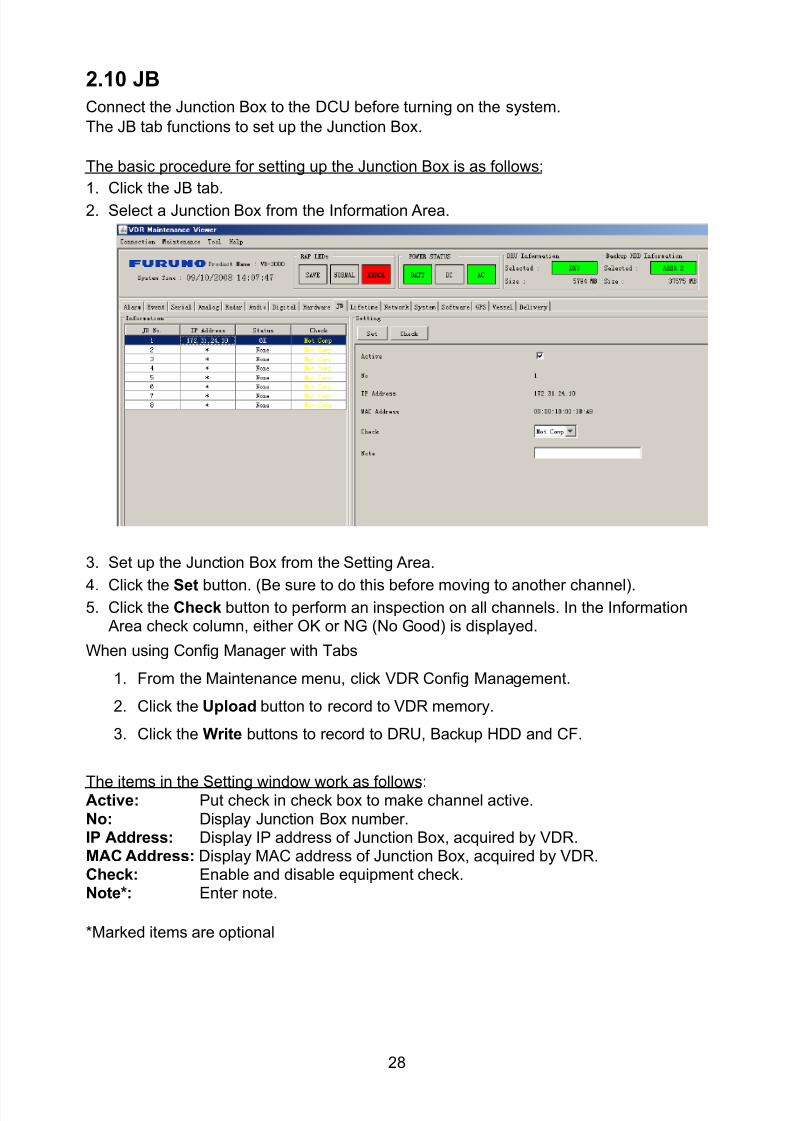
8102019 Ome44376d Vr3000 Mainte Cof26amp3bmol
httpslidepdfcomreaderfullome44376d-vr3000-mainte-cof26amp3bmol 3057
28
210 JB
Connect the Junction Box to the DCU before turning on the system
The JB tab functions to set up the Junction Box
The basic procedure for setting up the Junction Box is as follows
1 Click the JB tab2 Select a Junction Box from the Information Area
3 Set up the Junction Box from the Setting Area
4 Click the Set button (Be sure to do this before moving to another channel)5 Click the Check button to perform an inspection on all channels In the Information
Area check column either OK or NG (No Good) is displayed
When using Config Manager with Tabs
1 From the Maintenance menu click VDR Config Management
2 Click the Upload button to record to VDR memory
3 Click the Write buttons to record to DRU Backup HDD and CF
The items in the Setting window work as followsActive Put check in check box to make channel activeNo Display Junction Box numberIP Address Display IP address of Junction Box acquired by VDRMAC Address Display MAC address of Junction Box acquired by VDRCheck Enable and disable equipment checkNote Enter note
Marked items are optional
8102019 Ome44376d Vr3000 Mainte Cof26amp3bmol
httpslidepdfcomreaderfullome44376d-vr3000-mainte-cof26amp3bmol 3157
29
211 Life Time
The Life Time tab controls consumable parts
The basic procedure for using the Life Time tab is as follows
1 Click the Life Time tab
2 Select a Type No in the Information Area3 Set up the chosen part from Setting Area
4 Click the Set button
Note Be sure to click the Set button before moving to set up a different Type
The items in the Setting window work as follows
Type No Enter and display type no
Data Name Enter and display data name
Level Set replacement level Legal Exchange Parts or Normal Exchange Parts
Replace Date Enter and display recommended day of replacement
Lifetime Term Not usedNote Enter and display note
The Status column of the Information Area displays as follows
OK The recommended date of replacement shown in the Replace Date
box in the Information window has not passed
Out of Date The date of replacement has passed
None The date of replacement has not been set
8102019 Ome44376d Vr3000 Mainte Cof26amp3bmol
httpslidepdfcomreaderfullome44376d-vr3000-mainte-cof26amp3bmol 3257
30
212 Network
The Network tab sets the system network
The basic procedure for setting up the system network is as follows
1 Click the Network tab
2 Select a port from the Information Area
3 Set up the network from the Setting Area
4 Click the Set button
Note1 Be sure to click the Set button before moving to set up a different Port
Note2 After setting the system network reboot the VDR to apply the settings
The items in the Setting window work as follows
LAN Type Enter LAN type Public LAN or JB LAN
MAC Address Enter MAC address
IP Address Enter IP address
Subnet Mask Enter subnet mask
Gateway Address Enter gateway address
Live Play Multicast Mode (Only JB LAN) Check box to enable live player multicast
mode
Multicast Address (Only Public LAN) Enter and display live player multicast addressNote Enter note
Marked items are optional
8102019 Ome44376d Vr3000 Mainte Cof26amp3bmol
httpslidepdfcomreaderfullome44376d-vr3000-mainte-cof26amp3bmol 3357
31
213 System
The System tab sets system related functions
The basic procedure for using the System tab is as follows
1 Click the System tab
2 Set up the chosen item from the Setting Area
3 Click the Set button
Note Be sure to click the Set button before moving to a different tab
The items in the Setting window work as follows
VDR Type Enter type of VDR
VDR Model Enter model number of VDR
Radar Interface Check Enable and disable checking of the Radar Interface board
Junction Box Count Enter number of junction boxes in system
DRU Flash Count Enter number of DRU flash disks in system Set 1 when DRU
serial no is 5000 and more Set 3 when DRU serial no is less
than 5000
DRU Capacity Display capacity of DRU
Backup HDD Capacity Display capacity of Backup HDD
VDR Config Version Display version no of VDR
VDR Config Date Display the number of hours the VDR settings have
been saved
VDR Config Code Display configuration identity code
Installation Engineer Enter name of the equipment installer
Installation Company Enter name of installers company
8102019 Ome44376d Vr3000 Mainte Cof26amp3bmol
httpslidepdfcomreaderfullome44376d-vr3000-mainte-cof26amp3bmol 3457
32
Installation Date Enter the date of the installation
MIC Test Time Enter the date of the MIC test
Note Enter note Marked items are optional
USB memory logging Do not check Enable
IEEE1394 BUS Error Auto Restart function Not used
IEEE1394 Active Node Count Do not change the default value of 3 (However set to 5
for serial number 5000 or less of DRU)
IEEE1394 Recover Process Limit Count Do not change the default value of 10
DRU Error Auto Restart function Not used
REBOOT DELAY TIME (sec) Do not change the default value of 10
LIMIT REBOOT COUNT Do not change the default value of 10
Live Player Max Connection Count The max number of Live Player V4 that can be
connected simultaneously The default no is two
but a maximum of five can be set here After you
change this option reboot the VDR to apply the
setting Disconnect the cable connected with
Live Player V4 (PC) from the VDR and thenreconnect it
214 Software
The Software tab sets and display software-related operations
The basic procedure for using the Software tab is as follows
1 Click the Software tab
2 Set up the chosen Item from the Setting Area
3 Click the Set button
8102019 Ome44376d Vr3000 Mainte Cof26amp3bmol
httpslidepdfcomreaderfullome44376d-vr3000-mainte-cof26amp3bmol 3557
33
The items in the Setting window work as follows
VDR System Program Display the VDR system program no
Process Version Display the process version
Power Distribution Unit (PDU) Display the version no of the PDU
Operation System Display the version no of the OS
Audio Driver Display the version no of the audio driverRAP Version Enter the version no of the RAP
AP Version Enter the version no of the AP
JB1-8 Boot Program Display the no of the RJB Boot program for Junction Boxes
1 to 8
JB1-8 App Program Display the no of the RJB App program for Junction Boxes
1 to 8
Watch Dog Interval Do not change the default value of 60 (Enter the process
response time A process is repeated if there is no response
within the time interval set here)
Giveup Interval Do not change the default value of 300 (Enter the restart
watch time The restarting of a process is stopped when the
number of times it has been restarted is exceeded within the
interval set here)
Refork Limit Do not change the default value of 10 (Enter the upper limit
for process restart The restarting of a process is stopped
when the number of times it has been restarted exceeds the
Give up Interval)
Note Enter note
Marked Items are optional
8102019 Ome44376d Vr3000 Mainte Cof26amp3bmol
httpslidepdfcomreaderfullome44376d-vr3000-mainte-cof26amp3bmol 3657
34
215 GPS
The GPS tab sets GPS-related parameters
The basic procedure for using the GPS tab is as follows
1 Click the GPS tab
2 Set up the chosen channel from the Information window3 Set up the chosen item in the Setting Area
4 Click the Set button
5 Repeat steps 2-4 to set up each Channel
6 Click the Check button to perform an inspection on all channels In the Information Area check column either OK or NG (No Good) is displayed
The items in the Setting window work as follows
Priority Display priority order
Date and Time SourceShip Position Source Set GPS source channel (serial channel
number for ZDA sentence)
Check Enable and disable checking
GPS Antenna Position From Bow Enter position of GPS antenna from bow
GPS Antenna Position From Stern Enter position of GPS antenna from stern
GPS Antenna Position From Port Enter position of GPS antenna from port
GPS Antenna Position From Starboard Enter position of GPS antenna from starboard
GPS Failure Threshold If the ZDA is input within the set time limit
the system restarts synchronized If not
input within the time limit the system restarts
without synchronization
8102019 Ome44376d Vr3000 Mainte Cof26amp3bmol
httpslidepdfcomreaderfullome44376d-vr3000-mainte-cof26amp3bmol 3757
35
GPS Delay Time by Time Sync Enter minimum time delay for time
synchronization Time synchronization is started
only in the time set here
GPS Difference Interval The time set here is added to the GPS time to
synchronize the system time Leave at the default
0 value setting
GPS Sync Giveup Time If the system receives the GPS time within the
time set the system synchronizes with the time
When not receiving a signal the system displays
an ldquoerror 26rdquo message
ZDA Timeout Enter value (seconds) for ZDA timeout (234 error)
from GPS
Note Enter and display note
Marked Items are optional
216 VesselThe Vessel tab sets and displays own ships information such as name and IMO number
The basic procedure for using the Vessel tab is as follows
1 Click the Vessel tab
2 Set up information in the Setting window
3 Click the Set button (Be sure to do this before moving to another port)
4 From the Maintenance menu click VDR Config Management and then Config5 Click the Write buttons to save data to the DRU backup HDD CF
The buttons in the Setting window works as follows
Vessel Name Enter name of vessel
Vessel IMO Number Enter IMO number of vessel
Vessel Flag Enter flag of vessel
Approval of Authority Enter name of approving authority
Note Enter note
Marked items are optional
8102019 Ome44376d Vr3000 Mainte Cof26amp3bmol
httpslidepdfcomreaderfullome44376d-vr3000-mainte-cof26amp3bmol 3857
36
217 Delivery
The Delivery tab functions to transmit data from the VDR to a PC via Ethernet LAN Do
not use this function during live connection
The basic procedure for using the Delivery tab is as follows
1 Click the Delivery tab
2 Click the Add button to show the Delivery Config window
3 Select protocol from the Protocol drop-down box (Unicast or Multicast)
4 Enter IP address in the IP address input box
5 Enter port number in the port number input box
6 Click the tab of the data to send (Analog Digital or Serial)
7 Select the channel of the data to send
8 If Serial was selected at step 6 select applicable data sentence from the Inactivewindow Click the right arrow to move the data sentence to the Active window
9 Click the OK button to close the Delivery Config window
10 The settings are listed in a table in the Delivery window Check the checkbox in the
Active column and then click the Set button
The buttons in the Setting window works as follows
Set Save edited settings
Add Create new delivery settings
Modify Modify selected delivery settings
Delete Delete selected delivery settings
8102019 Ome44376d Vr3000 Mainte Cof26amp3bmol
httpslidepdfcomreaderfullome44376d-vr3000-mainte-cof26amp3bmol 3957
37
3 How to Back up Configuration DataThis chapter shows how to back up configuration data to various storage media
Configuration data can be opened with Word Pad or any text editor other than Notepad
31 How to Back up Configuration Data to the Startup CompactFlash (CF)
Back up data to the startup CF after setting the VDR Configuration data is created on the
CF as a configini file
Note When the error shown below occurs during the downloading or uploading of
configuration data check the connection of the DRU Backup HDD and CF and then
upload or download the configuration data again
[CONN] Download failed
[CONN] Could not upload config file
If error occurs again re-install the VDR Maintenance Viewer
Do the following to back up data to a CF
1 Set up parameters on the tabs referring to Chapter 2
2 Click the Maintenance menu
3 Select VDR Config Management
4 Click the Upload button
5 A confirmation box appears click the OK button to start uploading to the VDR
6 Click the Write button where the arrow connects between VDR and DRU BackupHDD
7 A confirmation window appears click the OK button to save the configuration data tothe DRU and Backup HDD
8102019 Ome44376d Vr3000 Mainte Cof26amp3bmol
httpslidepdfcomreaderfullome44376d-vr3000-mainte-cof26amp3bmol 4057
38
8 Click the Write button where the arrow connects between the VDR and CF
9 A confirmation window appears click the OK button to save the configuration data tothe startup CF
10 Check that the PC VDR DRU Backup HDD and CF share the same VDR configcode
32 How to Back up Configuration Data to a PC
Configuration data saved to the PC can be edited with Wordpad and shared with other
vessels For future service ease it is recommended to backup configuration data to the
PC and have the data on board the vessel Also it is recommended to upload this data to
Furuno SMS (Service Management System) If unable to upload to Furuno SMS please
contact the Service Center Furuno Japan
To back up configuration data to the PC do as follows
1 Set up parameters on the tabs referring to Chapter 2
2 Click the Maintenance menu
3 Select VDR Config Management
4 Click the Export to button
5 A confirmation window appears click the OK button
6 Select where to save the data enter file name then click the Open button
7 Confirm that back up file is in the location selected
33 How to restore the default settings
Click the Default button on the VDR Config Management window to restore the default
settings of the DRU Backup HDD CF and VDR Maintenance Viewer
8102019 Ome44376d Vr3000 Mainte Cof26amp3bmol
httpslidepdfcomreaderfullome44376d-vr3000-mainte-cof26amp3bmol 4157
39
4 How to Upload Configuration Datafrom a PCThe procedure below shows how to upload configuration from the PC to aVR-3000VR-3000S
1 Click the Maintenance menu
2 Select VDR Config Management
3 Click the Import from button
4 The Open window appears Select configuration data and then click the Open button
5 Click the Upload button to upload data to the VR-3000VR-3000S
6 Click the Write buttons to save data to the DRU backup HDD and CF
8102019 Ome44376d Vr3000 Mainte Cof26amp3bmol
httpslidepdfcomreaderfullome44376d-vr3000-mainte-cof26amp3bmol 4257
40
5 Media ManagementThe media management feature deletes data from recording media initialization the
system etc There are two method LAN connection and Direct connection The Direct
connection takes longer time than the LAN connection Basically use the LAN connection
method
Note Initialization or creation of recording media is not available when Source Select onthe Live Player V4 is selected to Backup HDD
51 Initialization
This section shows how to delete data from the recording media Configuration data is
not deleted After performing the software configuration delete the data from the DRU
and HDD
Do the following to delete data from the DRU (LAN connection)
1 Set the PlaybackCPU switch in the DCU to the CPU position
2 Use an Ethernet cross cable to connect the PC to J14 (DATA) in the DCU (See page5)
3 Open the Tool menu
4 Select Media Management to open the VDR Media Management window
5 Check that IP address shown in the ldquoLAN Connect to IPrdquo in VDR Media Table Area isthe same as the IP address access point
6 Select ldquoLAN Connect to IPrdquo in the VDR Media Table column
8102019 Ome44376d Vr3000 Mainte Cof26amp3bmol
httpslidepdfcomreaderfullome44376d-vr3000-mainte-cof26amp3bmol 4357
41
7 Click the Analyze button A list of recording media connected to the VDR appears
Put a checkmark in the checkbox of the Select column for the DRU in the Name columnNote If there are several flash memories in the DRU all flash memories are shownCheck all flash memories shown
8 Select ldquoDRU Initializerdquo from the Operation dropdown list in the Operation area
10 Click the Run button
Do the following to delete data from the DRU (Direct connection)
1 Start Live Player V4 software
2 Open the Tool menu and select Source Select Select Live from the pull-downmenu
3 Click the Alarm tab and open Alarm History
4 Set the PlaybackCPU switch in the DCU to the Playback position
5 Wait approx 10 minutes and confirm that Alarm 174 occurs on Alarm History of LivePlayer V4
6 Connect an IEEEE1394 cable between J6 in the DCU and the PC
7 Open the Tool menu
8 Select Media Management to show the VDR Media Management window
9 Select Direct in the VDR Media Table column
10 Click the Analyze button A list of recording media connected to the VDR appears
11 Put a checkmark in the checkbox of the Select column for the DRU in the Namecolumn
Note If there are several flash memories in the DRU all flash memories are shownCheck all flash memories shown
12 Select ldquoDRU Initializerdquo from the Operation dropdown list in the Operation area
13 Enter password in the password column
14 Click the RUN button
8102019 Ome44376d Vr3000 Mainte Cof26amp3bmol
httpslidepdfcomreaderfullome44376d-vr3000-mainte-cof26amp3bmol 4457
42
Delete data from the Backup HDD as follows (LAN connection)
1 Set the PlaybackCPU switch in the DCU to the CPU position
2 Check that an Ethernet cross cable is connected between J14 in the DCU and the PC
3 Open the Tool menu
4 Select Media Management to open the VDR Media Management window
5 Check that IP address shown in the LAN Connect to IP in VDR Media Table Area is
the same as the IP address access point6 Select LAN Connect to IP in the VDR Media Table column
7 Click the Analyze button
8 A list of recording media connected to the VDR appears
9 Put a checkmark in the box of the Select column for the Backup HDD in the Namecolumn Select ldquoBackup HDD Initializerdquo from the Operation dropdown list in theOperation area
10 Click the Run button
Delete data from the Backup HDD as follows (Direct connection)
1 Start Live Player V4 software
2 Open the Tool menu and select Source Select Select Live from the pull-downmenu
3 Click the Alarm tab and open Alarm History
4 Set the PlaybackCPU switch in the DCU to the Playback position
5 Wait approx 10 minutes and confirm that Alarm 174 occurs on Alarm History of LivePlayer V4
6 Connect an IEEE1394 cable between J6 in the DCU and the PC
7 Open the Tool menu
8 Select Media Management to open the VDR Media Management window9 Select Direct in the VDR Media Table window
10 Click the Analyze button A list of recording media connected to the VDR appears
11 Put a checkmark in the check box of the Select column for the Backup HDD in theName column Select ldquoBackup HDD Initializerdquo from the Operation dropdown list in theOperation area
12 Enter password
13 Click the Run button
8102019 Ome44376d Vr3000 Mainte Cof26amp3bmol
httpslidepdfcomreaderfullome44376d-vr3000-mainte-cof26amp3bmol 4557
43
52 CreationThe Creation feature initializes recording media
Note1 This feature deletes ALL configuration data Backup all VDR configuration data
Note2 When you initialize medium that is a different format for the DRU or Backup HDDdelete all partitions with the disk management tool of Windows
Note3 When the Creation is failed try again If you can not initialize recording media tryunder condition as shown below
Do the Creation by the direct connection (When the Creation by the LAN
connection is failed)
Delete all partitions of the DRU or Backup HDD with the disk management tool of
Windows to do the Creation
If the Creation is still failed request service to repairreplace the DRU or Backup
HDD
Initialize the DRU as follows (LAN connection)
1 Set the PlaybackCPU switch in the DCU to the CPU position
2 Check that an Ethernet cross cable is connected between J14 in the DCU and the PC
3 Open the Tool menu
4 Select Media Management to open the VDR Media Management window
5 Check that IP address shown in the LAN Connect to IP in VDR Media Table Area isthe same as the IP address access point
6 Check ldquoLAN Connect to IPrdquo in the VDR Media Table column
7 Click the Analyze button A list of recording media connected to the VDR appears
8 Put a checkmark in the box of the Select column for the DRU in the Name column
Select ldquoDRU Creationrdquo from the Operation dropdown list in the Operation area
9 Click the Run button
Initialize the Backup HDD as follows (LAN connection)
1 To format the Backup HDD place a checkmark in the Select column of the listedrecord media in the Name column of the VDR Media Management dialogue box
2 From the Operation drop down list of the Operation area select ldquoBackup HDDCreation (Radar) or ldquoBackup HDD Creationrdquo
Two partition tools are available for the Backup HDD in the Media Management as
below
Backup HDD creation
This tool is used when the number of the SXGA video signal connected to the BackupHDD is the same as the DRU The same partition is created on both DRU and HDD
(1) When two SXGA video signals are recorded onto the HDD while 9-GB DRU isconnected
(2) When an SXGA video signal is recorded onto the HDD while 6-GB DRU isconnected
Backup HDD creation (radar)
This tool is used when two SXGA video signals are recorded onto the HDD with 6-GB
DRU connected The HDD has an area (radar) to record the second radar signal inaddition to the same partition as the DRU This tool cannot be used when 9-GB DRUis connected
3 Press the Run Button
8102019 Ome44376d Vr3000 Mainte Cof26amp3bmol
httpslidepdfcomreaderfullome44376d-vr3000-mainte-cof26amp3bmol 4657
44
Initialize the DRU as follows (Direct connection)
1 Start Live Player V4 software
2 Open the Tool menu and select Source Select Select Live from the pull-downmenu
3 Click the Alarm tab and open Alarm History
4 Set the PlaybackCPU switch in the DCU to the Playback position
5 Wait approx 10 minutes and confirm that Alarm 174 occurs on Alarm History of LivePlayer V4
6 Connect an IEEE1394 cable between J6 in the DCU and the PC
7 Open the Tool menu
8 Select Media Management to open the VDR Media Management window
9 Select Direct in the VDR Media Table window
10 Click the Analyze button A list of recording media connected to the VDR appears
11 Put a checkmark in the box of the Select column for the DRU and the desiredrecording media in the Name column In the Operation dropdown list of the Operationarea select ldquoDRU Creationrdquo
12 Enter password in the password column
13 Click the Run button
Initialize the Backup HDD as follows (Direct Connection)
1 To format the Backup HDD place a checkmark in the Select column of the listedrecord media in the Name column of the VDR Media Management dialogue box
2 From the Operation column of the Operation area select ldquoBackup HDD Creation(Radar) or ldquoBackup HDD Creationrdquo
Backup HDD creation
This tool is used when the number of the SXGA video signal connected to the BackupHDD is the same as the DRU The same partition is created on both DRU and HDD
(1) When two SXGA video signals are recorded onto the HDD while 9-GB DRU is
connected
(2) When an SXGA video signal is recorded onto the HDD while 6-GB DRU is
connected
Backup HDD creation (radar)
This tool is used when two SXGA video signals are recorded onto the HDD with 6-GBDRU connected The HDD has an area (radar) to record the second radar signal inaddition to the same partition as the DRU This tool cannot be used when 9-GB DRUis connected
3 Enter the password in the Password column
4 Press the Run Button
8102019 Ome44376d Vr3000 Mainte Cof26amp3bmol
httpslidepdfcomreaderfullome44376d-vr3000-mainte-cof26amp3bmol 4757
45
53 How to Enable Recording Area on the Backup HDD
This function enables writing over a recording area To prevent falsification of data all
recording areas must be saved otherwise this function is disabled To use this function push
the SAVE button Save the data before doing this procedure
Note Software version 135 or higher can enable writing over a recording area even if
all recording areas are not saved
Recording enable (LAN connection)
1 Set the PlaybackCPU switch in the DCU to the CPU position
2 Check that an Ethernet cross cable is connected between J14 in the DCU and the PC
3 Open the Tool menu
4 Select Media Management to open the VDR Media Management window
5 Check that IP address shown in the ldquoLAN Connect to IPrdquo in VDR Media Table Area isthe same as the IP address access point
6 Select ldquoLAN Connect to IPrdquo in the VDR Media Table column7 Click the Analyze button A list of recording media connected to the VDR appears
8 Put a checkmark in the box of the Select column for the Backup HDD in the Namecolumn
9 Select ldquoBackup HDD Recording Area Enablerdquo from the Operation dropdown list in theOperation area
10 Click the Run button
Recording enable (Direct connection)
1 Start Live Player V4 software
2 Open the Tool menu and select Source Select Select Live from the pull-down menu3 Click the Alarm tab and open Alarm History
4 Set the PlaybackCPU switch in the DCU to the Playback position
5 Wait approx 10 minutes and confirm that Alarm 174 occurs on Alarm History of LivePlayer V4
6 Connect an IEEE1394 cable between J6 in the DCU and the PC
7 Open the Tool menu
8 Select Media Management to open the VDR Media Management window
9 Select Direct in the VDR Media Table window
10 Click the Analyze button A list of recording media connected to the VDR appears11 Put a checkmark in the box of the Select column for the Backup HDD in the Name
column
12 Select ldquoBackup HDD Recording Area Enablerdquo from the Operation dropdown list in theOperation area
13 Enter password
14 Click the Run button
8102019 Ome44376d Vr3000 Mainte Cof26amp3bmol
httpslidepdfcomreaderfullome44376d-vr3000-mainte-cof26amp3bmol 4857
46
6 Other Functions
61 Software Management
The software download feature downloads VDR system software to the PC
To download software
1 Click the Maintenance menu
2 From the Software Management menu click Software Download to show theSoftware Download window
3 Enter the IP address 1000100 in the IP address box in the Update Server area
4 Click the Download Software button
5 The confirmation window appears click the OK button
The Software Backup Execute window shows the results of the download
Software is downloaded to C Program Files VDR Viewer Viewer Backup The software file
name is vdrtar
To Update Software
VDR system program version 16x can update the software with the procedure shownbelow
Note Do not update the file downloaded in procedures above
1 Click the Maintenance menu
2 From the Software Management menu click Software Upload to show the SoftwareUpload area
3 Click the Select button to show the Open window
4 Select update file (vdrtar) and click the Open button
8102019 Ome44376d Vr3000 Mainte Cof26amp3bmol
httpslidepdfcomreaderfullome44376d-vr3000-mainte-cof26amp3bmol 4957
47
5 Check the displayed Software information is correct
6 Enter the IP address 1000100 in the IP address box in the Update Server area
7 Enter password
8 Click the Update button
After the updating is completed the VDR is automatically restarted
Note Click the Restore button on the Software Update window to restore previoussoftware version This feature is available after updating the software
62 Password Management
The password can be changed for a serviceman to access the equipment Contact
FURUNO to get the default password to use during installation
Serviceman password
1 Click the Maintenance menu2 Select Change Serviceman Password from Password Management to show the
Change Serviceman Password window
3 Enter current password in the Old Password box
4 Enter the new password in the New Password box of the Change Password area
5 Enter new password again in the Confirm New Password box
6 Click the OK button
Audio password
The audio password set at the VDR Maintenance Viewer can be removed to enable
audio access without password1 Click the Maintenance menu
2 Select Change Audio Password from Password Management to show the Change Audio Password window
3 The confirmation window appears click the OK button
8102019 Ome44376d Vr3000 Mainte Cof26amp3bmol
httpslidepdfcomreaderfullome44376d-vr3000-mainte-cof26amp3bmol 5057
48
63 Record ComparisonThe integrity of the DRU and Backup HDD recordings can be compared This function isused by the RampD engineer for debugging
Follow the procedure as shown below
1 Click the Maintenance menu2 Select Record Comparison to show the Record Comparison window
The results are shown every 15 seconds in the Record Comparison window
8102019 Ome44376d Vr3000 Mainte Cof26amp3bmol
httpslidepdfcomreaderfullome44376d-vr3000-mainte-cof26amp3bmol 5157
49
64 Software History
This section shows you to save and configure software history (communications record)
How to save software history
Note When the error dialog appears while saving the software history restart the VDR
Maintenance Viewer
1 Click the Maintenance menu
2 Select Software History Collect
3 Click the Select button The Open dialog box appears
4 Select where to save the data then click the Open button
5 Select desired save condition then click the OK buttonNone No savingAt Once Save the software history manually Saving begins as soon as the OK button is clickedPeriodic For debugging Do not use otherwise The intervals are 30 sec 60 secand 120 secAlarm Detection For debugging Do not use otherwise Software history is savedwhen specified alarm is released Enter alarm number
How to configure software communications record
The RampD engineer uses this function for debugging Do not do this procedure unless
required Malfunction can result
1 Click the Maintenance menu
2 Select Software History Config
3 Do the followingProcess Select the type of communications record to save ALL saves allcommunications records
Detail Hide or show detailed information4 Click the Send button
8102019 Ome44376d Vr3000 Mainte Cof26amp3bmol
httpslidepdfcomreaderfullome44376d-vr3000-mainte-cof26amp3bmol 5257
50
65 Easy SetupThis feature sets equipment settings in batch and creates a data file of those settings
Default template The default template is created with the settings entered at installation
1 Click the Maintenance menu
2 Select Easy Setup to show the Template Selection window
3 Select Default Template
4 Click the Start button to show the Easy Setup window
5 Right click the channels (Radar Audio Digital Serial Analog) then select Edit toshow the Equipment Selection window
6 From the Equipment Directory window select equipment connected to the selectedchannel and then click the OK button
7 Repeat steps 5 and 6 to select equipment settings for each channel
8 Click the Save button in the Easy Setup window to show the Save window
9 Select where to save the file and enter file name
10 Click the Save button
8102019 Ome44376d Vr3000 Mainte Cof26amp3bmol
httpslidepdfcomreaderfullome44376d-vr3000-mainte-cof26amp3bmol 5357
51
Specific template Use a file already created
1 Click the Maintenance menu
2 Select Easy Setup to show the Template Selection window
3 Check Specified Template
4 Click the Select button and then select the file to edit
5 Click the Start button to show the Easy Setup window
6 Right click the channels (Radar Audio Digital Serial Analog) then select Edit toshow the Equipment Selection window
7 From the Equipment Directory window select equipment connected to the selectedchannel and then click the OK button
8 Repeat steps 6 and 7 to select equipment settings for each channel
9 Click the Save button in the Easy Setup window to show the Save window
10Select where to save the file and enter file name
11 Click the Save button
66 Equipment Management
This feature controls the import and export of equipment settings
Import data file
Import data files of equipment settings created in Easy Setup etc to the VDR
1 Click the Maintenance menu
2 Select Import from Equipment Management to show the Open window
3 Select the data file to import and click Open
Export data file
Export data files of equipment settings from the VDR to a PC
1 Click the Maintenance menu
2 Select Export from Equipment Management to show the Save window
3 Enter file name
4 Click the Save button
8102019 Ome44376d Vr3000 Mainte Cof26amp3bmol
httpslidepdfcomreaderfullome44376d-vr3000-mainte-cof26amp3bmol 5457
52
67 PC_RAP
This feature enables the same operation of the RAP (Remote Alarm Panel) from a PC
Select PC_RAP from the Tool menu to show the PC_RAP window
The buttons in the PC_RAP window function as shown below
SAVE Stop recording in the area where recording is currently being done
ACK Silence audio alarm
The PC_RAP display shows the following information with LEDs
RAP_LEDs Display the status of LEDs on the RAPSave The Save button blinks yellow when pushed When the 4 memory
areas have data recorded to them the Save button lights orange when
pushed
Normal Lights (green) where there are no unconfirmed or not restored
alarms
Error Flashes (red) for not confirmed alarm Lights (red) for unrestored
alarm
8102019 Ome44376d Vr3000 Mainte Cof26amp3bmol
httpslidepdfcomreaderfullome44376d-vr3000-mainte-cof26amp3bmol 5557
53
Backup HDD Information Display status of backup HDD
Selected Display current recording area and its status in green for
normal operation and in red for abnormal operation
Size Display capacity of backup HDD
Alarm area displays unconfirmed alarms
Time Display time alarm was generatedNumber Display number of alarm
Name Display name of alarm
Pending Alarm displays the unrestored alarms out of confirmed alarms only
Time Display time alarm was generated
Number Display number of alarm
Name Display name of alarm
8102019 Ome44376d Vr3000 Mainte Cof26amp3bmol
httpslidepdfcomreaderfullome44376d-vr3000-mainte-cof26amp3bmol 5657
54
68 Other
Status Monitor
The status monitor feature provides comprehensive data about the status of the VDR
From the menu bar click Toolgt Status Monitor to show the Status Monitor window
The buttons in the Status Monitor window work as shown below
Reload Settings for automatic refreshing of the status monitor
ON Turn automatic refresh OFF
OFF The Status Monitor is refreshed every five seconds
Save Available when Reload ON is selected The contents of the Status Monitor can be
saved to a text fileUpdate Update the Status Monitor display
Close Close the Status Monitor display
8102019 Ome44376d Vr3000 Mainte Cof26amp3bmol
httpslidepdfcomreaderfullome44376d-vr3000-mainte-cof26amp3bmol 5757
VDR Error List
This feature compiles all the errors shown on the RAP for easy reference
Access from MenugtToolgtVDR Error List
The VDR error list contains the following information
NO Display the number of the error
Title Display the name of the error
Detail Display details about the error
Exchange Check
This feature removes the alarms generated when replacing the DRU or backup HDD
Access MenugtToolgtExchange Check select either DRU or Backup HDD and click OK
Reboot
Reboot the VDR
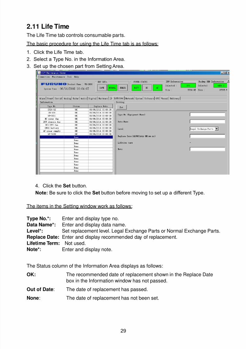
8102019 Ome44376d Vr3000 Mainte Cof26amp3bmol
httpslidepdfcomreaderfullome44376d-vr3000-mainte-cof26amp3bmol 3157
29
211 Life Time
The Life Time tab controls consumable parts
The basic procedure for using the Life Time tab is as follows
1 Click the Life Time tab
2 Select a Type No in the Information Area3 Set up the chosen part from Setting Area
4 Click the Set button
Note Be sure to click the Set button before moving to set up a different Type
The items in the Setting window work as follows
Type No Enter and display type no
Data Name Enter and display data name
Level Set replacement level Legal Exchange Parts or Normal Exchange Parts
Replace Date Enter and display recommended day of replacement
Lifetime Term Not usedNote Enter and display note
The Status column of the Information Area displays as follows
OK The recommended date of replacement shown in the Replace Date
box in the Information window has not passed
Out of Date The date of replacement has passed
None The date of replacement has not been set
8102019 Ome44376d Vr3000 Mainte Cof26amp3bmol
httpslidepdfcomreaderfullome44376d-vr3000-mainte-cof26amp3bmol 3257
30
212 Network
The Network tab sets the system network
The basic procedure for setting up the system network is as follows
1 Click the Network tab
2 Select a port from the Information Area
3 Set up the network from the Setting Area
4 Click the Set button
Note1 Be sure to click the Set button before moving to set up a different Port
Note2 After setting the system network reboot the VDR to apply the settings
The items in the Setting window work as follows
LAN Type Enter LAN type Public LAN or JB LAN
MAC Address Enter MAC address
IP Address Enter IP address
Subnet Mask Enter subnet mask
Gateway Address Enter gateway address
Live Play Multicast Mode (Only JB LAN) Check box to enable live player multicast
mode
Multicast Address (Only Public LAN) Enter and display live player multicast addressNote Enter note
Marked items are optional
8102019 Ome44376d Vr3000 Mainte Cof26amp3bmol
httpslidepdfcomreaderfullome44376d-vr3000-mainte-cof26amp3bmol 3357
31
213 System
The System tab sets system related functions
The basic procedure for using the System tab is as follows
1 Click the System tab
2 Set up the chosen item from the Setting Area
3 Click the Set button
Note Be sure to click the Set button before moving to a different tab
The items in the Setting window work as follows
VDR Type Enter type of VDR
VDR Model Enter model number of VDR
Radar Interface Check Enable and disable checking of the Radar Interface board
Junction Box Count Enter number of junction boxes in system
DRU Flash Count Enter number of DRU flash disks in system Set 1 when DRU
serial no is 5000 and more Set 3 when DRU serial no is less
than 5000
DRU Capacity Display capacity of DRU
Backup HDD Capacity Display capacity of Backup HDD
VDR Config Version Display version no of VDR
VDR Config Date Display the number of hours the VDR settings have
been saved
VDR Config Code Display configuration identity code
Installation Engineer Enter name of the equipment installer
Installation Company Enter name of installers company
8102019 Ome44376d Vr3000 Mainte Cof26amp3bmol
httpslidepdfcomreaderfullome44376d-vr3000-mainte-cof26amp3bmol 3457
32
Installation Date Enter the date of the installation
MIC Test Time Enter the date of the MIC test
Note Enter note Marked items are optional
USB memory logging Do not check Enable
IEEE1394 BUS Error Auto Restart function Not used
IEEE1394 Active Node Count Do not change the default value of 3 (However set to 5
for serial number 5000 or less of DRU)
IEEE1394 Recover Process Limit Count Do not change the default value of 10
DRU Error Auto Restart function Not used
REBOOT DELAY TIME (sec) Do not change the default value of 10
LIMIT REBOOT COUNT Do not change the default value of 10
Live Player Max Connection Count The max number of Live Player V4 that can be
connected simultaneously The default no is two
but a maximum of five can be set here After you
change this option reboot the VDR to apply the
setting Disconnect the cable connected with
Live Player V4 (PC) from the VDR and thenreconnect it
214 Software
The Software tab sets and display software-related operations
The basic procedure for using the Software tab is as follows
1 Click the Software tab
2 Set up the chosen Item from the Setting Area
3 Click the Set button
8102019 Ome44376d Vr3000 Mainte Cof26amp3bmol
httpslidepdfcomreaderfullome44376d-vr3000-mainte-cof26amp3bmol 3557
33
The items in the Setting window work as follows
VDR System Program Display the VDR system program no
Process Version Display the process version
Power Distribution Unit (PDU) Display the version no of the PDU
Operation System Display the version no of the OS
Audio Driver Display the version no of the audio driverRAP Version Enter the version no of the RAP
AP Version Enter the version no of the AP
JB1-8 Boot Program Display the no of the RJB Boot program for Junction Boxes
1 to 8
JB1-8 App Program Display the no of the RJB App program for Junction Boxes
1 to 8
Watch Dog Interval Do not change the default value of 60 (Enter the process
response time A process is repeated if there is no response
within the time interval set here)
Giveup Interval Do not change the default value of 300 (Enter the restart
watch time The restarting of a process is stopped when the
number of times it has been restarted is exceeded within the
interval set here)
Refork Limit Do not change the default value of 10 (Enter the upper limit
for process restart The restarting of a process is stopped
when the number of times it has been restarted exceeds the
Give up Interval)
Note Enter note
Marked Items are optional
8102019 Ome44376d Vr3000 Mainte Cof26amp3bmol
httpslidepdfcomreaderfullome44376d-vr3000-mainte-cof26amp3bmol 3657
34
215 GPS
The GPS tab sets GPS-related parameters
The basic procedure for using the GPS tab is as follows
1 Click the GPS tab
2 Set up the chosen channel from the Information window3 Set up the chosen item in the Setting Area
4 Click the Set button
5 Repeat steps 2-4 to set up each Channel
6 Click the Check button to perform an inspection on all channels In the Information Area check column either OK or NG (No Good) is displayed
The items in the Setting window work as follows
Priority Display priority order
Date and Time SourceShip Position Source Set GPS source channel (serial channel
number for ZDA sentence)
Check Enable and disable checking
GPS Antenna Position From Bow Enter position of GPS antenna from bow
GPS Antenna Position From Stern Enter position of GPS antenna from stern
GPS Antenna Position From Port Enter position of GPS antenna from port
GPS Antenna Position From Starboard Enter position of GPS antenna from starboard
GPS Failure Threshold If the ZDA is input within the set time limit
the system restarts synchronized If not
input within the time limit the system restarts
without synchronization
8102019 Ome44376d Vr3000 Mainte Cof26amp3bmol
httpslidepdfcomreaderfullome44376d-vr3000-mainte-cof26amp3bmol 3757
35
GPS Delay Time by Time Sync Enter minimum time delay for time
synchronization Time synchronization is started
only in the time set here
GPS Difference Interval The time set here is added to the GPS time to
synchronize the system time Leave at the default
0 value setting
GPS Sync Giveup Time If the system receives the GPS time within the
time set the system synchronizes with the time
When not receiving a signal the system displays
an ldquoerror 26rdquo message
ZDA Timeout Enter value (seconds) for ZDA timeout (234 error)
from GPS
Note Enter and display note
Marked Items are optional
216 VesselThe Vessel tab sets and displays own ships information such as name and IMO number
The basic procedure for using the Vessel tab is as follows
1 Click the Vessel tab
2 Set up information in the Setting window
3 Click the Set button (Be sure to do this before moving to another port)
4 From the Maintenance menu click VDR Config Management and then Config5 Click the Write buttons to save data to the DRU backup HDD CF
The buttons in the Setting window works as follows
Vessel Name Enter name of vessel
Vessel IMO Number Enter IMO number of vessel
Vessel Flag Enter flag of vessel
Approval of Authority Enter name of approving authority
Note Enter note
Marked items are optional
8102019 Ome44376d Vr3000 Mainte Cof26amp3bmol
httpslidepdfcomreaderfullome44376d-vr3000-mainte-cof26amp3bmol 3857
36
217 Delivery
The Delivery tab functions to transmit data from the VDR to a PC via Ethernet LAN Do
not use this function during live connection
The basic procedure for using the Delivery tab is as follows
1 Click the Delivery tab
2 Click the Add button to show the Delivery Config window
3 Select protocol from the Protocol drop-down box (Unicast or Multicast)
4 Enter IP address in the IP address input box
5 Enter port number in the port number input box
6 Click the tab of the data to send (Analog Digital or Serial)
7 Select the channel of the data to send
8 If Serial was selected at step 6 select applicable data sentence from the Inactivewindow Click the right arrow to move the data sentence to the Active window
9 Click the OK button to close the Delivery Config window
10 The settings are listed in a table in the Delivery window Check the checkbox in the
Active column and then click the Set button
The buttons in the Setting window works as follows
Set Save edited settings
Add Create new delivery settings
Modify Modify selected delivery settings
Delete Delete selected delivery settings
8102019 Ome44376d Vr3000 Mainte Cof26amp3bmol
httpslidepdfcomreaderfullome44376d-vr3000-mainte-cof26amp3bmol 3957
37
3 How to Back up Configuration DataThis chapter shows how to back up configuration data to various storage media
Configuration data can be opened with Word Pad or any text editor other than Notepad
31 How to Back up Configuration Data to the Startup CompactFlash (CF)
Back up data to the startup CF after setting the VDR Configuration data is created on the
CF as a configini file
Note When the error shown below occurs during the downloading or uploading of
configuration data check the connection of the DRU Backup HDD and CF and then
upload or download the configuration data again
[CONN] Download failed
[CONN] Could not upload config file
If error occurs again re-install the VDR Maintenance Viewer
Do the following to back up data to a CF
1 Set up parameters on the tabs referring to Chapter 2
2 Click the Maintenance menu
3 Select VDR Config Management
4 Click the Upload button
5 A confirmation box appears click the OK button to start uploading to the VDR
6 Click the Write button where the arrow connects between VDR and DRU BackupHDD
7 A confirmation window appears click the OK button to save the configuration data tothe DRU and Backup HDD
8102019 Ome44376d Vr3000 Mainte Cof26amp3bmol
httpslidepdfcomreaderfullome44376d-vr3000-mainte-cof26amp3bmol 4057
38
8 Click the Write button where the arrow connects between the VDR and CF
9 A confirmation window appears click the OK button to save the configuration data tothe startup CF
10 Check that the PC VDR DRU Backup HDD and CF share the same VDR configcode
32 How to Back up Configuration Data to a PC
Configuration data saved to the PC can be edited with Wordpad and shared with other
vessels For future service ease it is recommended to backup configuration data to the
PC and have the data on board the vessel Also it is recommended to upload this data to
Furuno SMS (Service Management System) If unable to upload to Furuno SMS please
contact the Service Center Furuno Japan
To back up configuration data to the PC do as follows
1 Set up parameters on the tabs referring to Chapter 2
2 Click the Maintenance menu
3 Select VDR Config Management
4 Click the Export to button
5 A confirmation window appears click the OK button
6 Select where to save the data enter file name then click the Open button
7 Confirm that back up file is in the location selected
33 How to restore the default settings
Click the Default button on the VDR Config Management window to restore the default
settings of the DRU Backup HDD CF and VDR Maintenance Viewer
8102019 Ome44376d Vr3000 Mainte Cof26amp3bmol
httpslidepdfcomreaderfullome44376d-vr3000-mainte-cof26amp3bmol 4157
39
4 How to Upload Configuration Datafrom a PCThe procedure below shows how to upload configuration from the PC to aVR-3000VR-3000S
1 Click the Maintenance menu
2 Select VDR Config Management
3 Click the Import from button
4 The Open window appears Select configuration data and then click the Open button
5 Click the Upload button to upload data to the VR-3000VR-3000S
6 Click the Write buttons to save data to the DRU backup HDD and CF
8102019 Ome44376d Vr3000 Mainte Cof26amp3bmol
httpslidepdfcomreaderfullome44376d-vr3000-mainte-cof26amp3bmol 4257
40
5 Media ManagementThe media management feature deletes data from recording media initialization the
system etc There are two method LAN connection and Direct connection The Direct
connection takes longer time than the LAN connection Basically use the LAN connection
method
Note Initialization or creation of recording media is not available when Source Select onthe Live Player V4 is selected to Backup HDD
51 Initialization
This section shows how to delete data from the recording media Configuration data is
not deleted After performing the software configuration delete the data from the DRU
and HDD
Do the following to delete data from the DRU (LAN connection)
1 Set the PlaybackCPU switch in the DCU to the CPU position
2 Use an Ethernet cross cable to connect the PC to J14 (DATA) in the DCU (See page5)
3 Open the Tool menu
4 Select Media Management to open the VDR Media Management window
5 Check that IP address shown in the ldquoLAN Connect to IPrdquo in VDR Media Table Area isthe same as the IP address access point
6 Select ldquoLAN Connect to IPrdquo in the VDR Media Table column
8102019 Ome44376d Vr3000 Mainte Cof26amp3bmol
httpslidepdfcomreaderfullome44376d-vr3000-mainte-cof26amp3bmol 4357
41
7 Click the Analyze button A list of recording media connected to the VDR appears
Put a checkmark in the checkbox of the Select column for the DRU in the Name columnNote If there are several flash memories in the DRU all flash memories are shownCheck all flash memories shown
8 Select ldquoDRU Initializerdquo from the Operation dropdown list in the Operation area
10 Click the Run button
Do the following to delete data from the DRU (Direct connection)
1 Start Live Player V4 software
2 Open the Tool menu and select Source Select Select Live from the pull-downmenu
3 Click the Alarm tab and open Alarm History
4 Set the PlaybackCPU switch in the DCU to the Playback position
5 Wait approx 10 minutes and confirm that Alarm 174 occurs on Alarm History of LivePlayer V4
6 Connect an IEEEE1394 cable between J6 in the DCU and the PC
7 Open the Tool menu
8 Select Media Management to show the VDR Media Management window
9 Select Direct in the VDR Media Table column
10 Click the Analyze button A list of recording media connected to the VDR appears
11 Put a checkmark in the checkbox of the Select column for the DRU in the Namecolumn
Note If there are several flash memories in the DRU all flash memories are shownCheck all flash memories shown
12 Select ldquoDRU Initializerdquo from the Operation dropdown list in the Operation area
13 Enter password in the password column
14 Click the RUN button
8102019 Ome44376d Vr3000 Mainte Cof26amp3bmol
httpslidepdfcomreaderfullome44376d-vr3000-mainte-cof26amp3bmol 4457
42
Delete data from the Backup HDD as follows (LAN connection)
1 Set the PlaybackCPU switch in the DCU to the CPU position
2 Check that an Ethernet cross cable is connected between J14 in the DCU and the PC
3 Open the Tool menu
4 Select Media Management to open the VDR Media Management window
5 Check that IP address shown in the LAN Connect to IP in VDR Media Table Area is
the same as the IP address access point6 Select LAN Connect to IP in the VDR Media Table column
7 Click the Analyze button
8 A list of recording media connected to the VDR appears
9 Put a checkmark in the box of the Select column for the Backup HDD in the Namecolumn Select ldquoBackup HDD Initializerdquo from the Operation dropdown list in theOperation area
10 Click the Run button
Delete data from the Backup HDD as follows (Direct connection)
1 Start Live Player V4 software
2 Open the Tool menu and select Source Select Select Live from the pull-downmenu
3 Click the Alarm tab and open Alarm History
4 Set the PlaybackCPU switch in the DCU to the Playback position
5 Wait approx 10 minutes and confirm that Alarm 174 occurs on Alarm History of LivePlayer V4
6 Connect an IEEE1394 cable between J6 in the DCU and the PC
7 Open the Tool menu
8 Select Media Management to open the VDR Media Management window9 Select Direct in the VDR Media Table window
10 Click the Analyze button A list of recording media connected to the VDR appears
11 Put a checkmark in the check box of the Select column for the Backup HDD in theName column Select ldquoBackup HDD Initializerdquo from the Operation dropdown list in theOperation area
12 Enter password
13 Click the Run button
8102019 Ome44376d Vr3000 Mainte Cof26amp3bmol
httpslidepdfcomreaderfullome44376d-vr3000-mainte-cof26amp3bmol 4557
43
52 CreationThe Creation feature initializes recording media
Note1 This feature deletes ALL configuration data Backup all VDR configuration data
Note2 When you initialize medium that is a different format for the DRU or Backup HDDdelete all partitions with the disk management tool of Windows
Note3 When the Creation is failed try again If you can not initialize recording media tryunder condition as shown below
Do the Creation by the direct connection (When the Creation by the LAN
connection is failed)
Delete all partitions of the DRU or Backup HDD with the disk management tool of
Windows to do the Creation
If the Creation is still failed request service to repairreplace the DRU or Backup
HDD
Initialize the DRU as follows (LAN connection)
1 Set the PlaybackCPU switch in the DCU to the CPU position
2 Check that an Ethernet cross cable is connected between J14 in the DCU and the PC
3 Open the Tool menu
4 Select Media Management to open the VDR Media Management window
5 Check that IP address shown in the LAN Connect to IP in VDR Media Table Area isthe same as the IP address access point
6 Check ldquoLAN Connect to IPrdquo in the VDR Media Table column
7 Click the Analyze button A list of recording media connected to the VDR appears
8 Put a checkmark in the box of the Select column for the DRU in the Name column
Select ldquoDRU Creationrdquo from the Operation dropdown list in the Operation area
9 Click the Run button
Initialize the Backup HDD as follows (LAN connection)
1 To format the Backup HDD place a checkmark in the Select column of the listedrecord media in the Name column of the VDR Media Management dialogue box
2 From the Operation drop down list of the Operation area select ldquoBackup HDDCreation (Radar) or ldquoBackup HDD Creationrdquo
Two partition tools are available for the Backup HDD in the Media Management as
below
Backup HDD creation
This tool is used when the number of the SXGA video signal connected to the BackupHDD is the same as the DRU The same partition is created on both DRU and HDD
(1) When two SXGA video signals are recorded onto the HDD while 9-GB DRU isconnected
(2) When an SXGA video signal is recorded onto the HDD while 6-GB DRU isconnected
Backup HDD creation (radar)
This tool is used when two SXGA video signals are recorded onto the HDD with 6-GB
DRU connected The HDD has an area (radar) to record the second radar signal inaddition to the same partition as the DRU This tool cannot be used when 9-GB DRUis connected
3 Press the Run Button
8102019 Ome44376d Vr3000 Mainte Cof26amp3bmol
httpslidepdfcomreaderfullome44376d-vr3000-mainte-cof26amp3bmol 4657
44
Initialize the DRU as follows (Direct connection)
1 Start Live Player V4 software
2 Open the Tool menu and select Source Select Select Live from the pull-downmenu
3 Click the Alarm tab and open Alarm History
4 Set the PlaybackCPU switch in the DCU to the Playback position
5 Wait approx 10 minutes and confirm that Alarm 174 occurs on Alarm History of LivePlayer V4
6 Connect an IEEE1394 cable between J6 in the DCU and the PC
7 Open the Tool menu
8 Select Media Management to open the VDR Media Management window
9 Select Direct in the VDR Media Table window
10 Click the Analyze button A list of recording media connected to the VDR appears
11 Put a checkmark in the box of the Select column for the DRU and the desiredrecording media in the Name column In the Operation dropdown list of the Operationarea select ldquoDRU Creationrdquo
12 Enter password in the password column
13 Click the Run button
Initialize the Backup HDD as follows (Direct Connection)
1 To format the Backup HDD place a checkmark in the Select column of the listedrecord media in the Name column of the VDR Media Management dialogue box
2 From the Operation column of the Operation area select ldquoBackup HDD Creation(Radar) or ldquoBackup HDD Creationrdquo
Backup HDD creation
This tool is used when the number of the SXGA video signal connected to the BackupHDD is the same as the DRU The same partition is created on both DRU and HDD
(1) When two SXGA video signals are recorded onto the HDD while 9-GB DRU is
connected
(2) When an SXGA video signal is recorded onto the HDD while 6-GB DRU is
connected
Backup HDD creation (radar)
This tool is used when two SXGA video signals are recorded onto the HDD with 6-GBDRU connected The HDD has an area (radar) to record the second radar signal inaddition to the same partition as the DRU This tool cannot be used when 9-GB DRUis connected
3 Enter the password in the Password column
4 Press the Run Button
8102019 Ome44376d Vr3000 Mainte Cof26amp3bmol
httpslidepdfcomreaderfullome44376d-vr3000-mainte-cof26amp3bmol 4757
45
53 How to Enable Recording Area on the Backup HDD
This function enables writing over a recording area To prevent falsification of data all
recording areas must be saved otherwise this function is disabled To use this function push
the SAVE button Save the data before doing this procedure
Note Software version 135 or higher can enable writing over a recording area even if
all recording areas are not saved
Recording enable (LAN connection)
1 Set the PlaybackCPU switch in the DCU to the CPU position
2 Check that an Ethernet cross cable is connected between J14 in the DCU and the PC
3 Open the Tool menu
4 Select Media Management to open the VDR Media Management window
5 Check that IP address shown in the ldquoLAN Connect to IPrdquo in VDR Media Table Area isthe same as the IP address access point
6 Select ldquoLAN Connect to IPrdquo in the VDR Media Table column7 Click the Analyze button A list of recording media connected to the VDR appears
8 Put a checkmark in the box of the Select column for the Backup HDD in the Namecolumn
9 Select ldquoBackup HDD Recording Area Enablerdquo from the Operation dropdown list in theOperation area
10 Click the Run button
Recording enable (Direct connection)
1 Start Live Player V4 software
2 Open the Tool menu and select Source Select Select Live from the pull-down menu3 Click the Alarm tab and open Alarm History
4 Set the PlaybackCPU switch in the DCU to the Playback position
5 Wait approx 10 minutes and confirm that Alarm 174 occurs on Alarm History of LivePlayer V4
6 Connect an IEEE1394 cable between J6 in the DCU and the PC
7 Open the Tool menu
8 Select Media Management to open the VDR Media Management window
9 Select Direct in the VDR Media Table window
10 Click the Analyze button A list of recording media connected to the VDR appears11 Put a checkmark in the box of the Select column for the Backup HDD in the Name
column
12 Select ldquoBackup HDD Recording Area Enablerdquo from the Operation dropdown list in theOperation area
13 Enter password
14 Click the Run button
8102019 Ome44376d Vr3000 Mainte Cof26amp3bmol
httpslidepdfcomreaderfullome44376d-vr3000-mainte-cof26amp3bmol 4857
46
6 Other Functions
61 Software Management
The software download feature downloads VDR system software to the PC
To download software
1 Click the Maintenance menu
2 From the Software Management menu click Software Download to show theSoftware Download window
3 Enter the IP address 1000100 in the IP address box in the Update Server area
4 Click the Download Software button
5 The confirmation window appears click the OK button
The Software Backup Execute window shows the results of the download
Software is downloaded to C Program Files VDR Viewer Viewer Backup The software file
name is vdrtar
To Update Software
VDR system program version 16x can update the software with the procedure shownbelow
Note Do not update the file downloaded in procedures above
1 Click the Maintenance menu
2 From the Software Management menu click Software Upload to show the SoftwareUpload area
3 Click the Select button to show the Open window
4 Select update file (vdrtar) and click the Open button
8102019 Ome44376d Vr3000 Mainte Cof26amp3bmol
httpslidepdfcomreaderfullome44376d-vr3000-mainte-cof26amp3bmol 4957
47
5 Check the displayed Software information is correct
6 Enter the IP address 1000100 in the IP address box in the Update Server area
7 Enter password
8 Click the Update button
After the updating is completed the VDR is automatically restarted
Note Click the Restore button on the Software Update window to restore previoussoftware version This feature is available after updating the software
62 Password Management
The password can be changed for a serviceman to access the equipment Contact
FURUNO to get the default password to use during installation
Serviceman password
1 Click the Maintenance menu2 Select Change Serviceman Password from Password Management to show the
Change Serviceman Password window
3 Enter current password in the Old Password box
4 Enter the new password in the New Password box of the Change Password area
5 Enter new password again in the Confirm New Password box
6 Click the OK button
Audio password
The audio password set at the VDR Maintenance Viewer can be removed to enable
audio access without password1 Click the Maintenance menu
2 Select Change Audio Password from Password Management to show the Change Audio Password window
3 The confirmation window appears click the OK button
8102019 Ome44376d Vr3000 Mainte Cof26amp3bmol
httpslidepdfcomreaderfullome44376d-vr3000-mainte-cof26amp3bmol 5057
48
63 Record ComparisonThe integrity of the DRU and Backup HDD recordings can be compared This function isused by the RampD engineer for debugging
Follow the procedure as shown below
1 Click the Maintenance menu2 Select Record Comparison to show the Record Comparison window
The results are shown every 15 seconds in the Record Comparison window
8102019 Ome44376d Vr3000 Mainte Cof26amp3bmol
httpslidepdfcomreaderfullome44376d-vr3000-mainte-cof26amp3bmol 5157
49
64 Software History
This section shows you to save and configure software history (communications record)
How to save software history
Note When the error dialog appears while saving the software history restart the VDR
Maintenance Viewer
1 Click the Maintenance menu
2 Select Software History Collect
3 Click the Select button The Open dialog box appears
4 Select where to save the data then click the Open button
5 Select desired save condition then click the OK buttonNone No savingAt Once Save the software history manually Saving begins as soon as the OK button is clickedPeriodic For debugging Do not use otherwise The intervals are 30 sec 60 secand 120 secAlarm Detection For debugging Do not use otherwise Software history is savedwhen specified alarm is released Enter alarm number
How to configure software communications record
The RampD engineer uses this function for debugging Do not do this procedure unless
required Malfunction can result
1 Click the Maintenance menu
2 Select Software History Config
3 Do the followingProcess Select the type of communications record to save ALL saves allcommunications records
Detail Hide or show detailed information4 Click the Send button
8102019 Ome44376d Vr3000 Mainte Cof26amp3bmol
httpslidepdfcomreaderfullome44376d-vr3000-mainte-cof26amp3bmol 5257
50
65 Easy SetupThis feature sets equipment settings in batch and creates a data file of those settings
Default template The default template is created with the settings entered at installation
1 Click the Maintenance menu
2 Select Easy Setup to show the Template Selection window
3 Select Default Template
4 Click the Start button to show the Easy Setup window
5 Right click the channels (Radar Audio Digital Serial Analog) then select Edit toshow the Equipment Selection window
6 From the Equipment Directory window select equipment connected to the selectedchannel and then click the OK button
7 Repeat steps 5 and 6 to select equipment settings for each channel
8 Click the Save button in the Easy Setup window to show the Save window
9 Select where to save the file and enter file name
10 Click the Save button
8102019 Ome44376d Vr3000 Mainte Cof26amp3bmol
httpslidepdfcomreaderfullome44376d-vr3000-mainte-cof26amp3bmol 5357
51
Specific template Use a file already created
1 Click the Maintenance menu
2 Select Easy Setup to show the Template Selection window
3 Check Specified Template
4 Click the Select button and then select the file to edit
5 Click the Start button to show the Easy Setup window
6 Right click the channels (Radar Audio Digital Serial Analog) then select Edit toshow the Equipment Selection window
7 From the Equipment Directory window select equipment connected to the selectedchannel and then click the OK button
8 Repeat steps 6 and 7 to select equipment settings for each channel
9 Click the Save button in the Easy Setup window to show the Save window
10Select where to save the file and enter file name
11 Click the Save button
66 Equipment Management
This feature controls the import and export of equipment settings
Import data file
Import data files of equipment settings created in Easy Setup etc to the VDR
1 Click the Maintenance menu
2 Select Import from Equipment Management to show the Open window
3 Select the data file to import and click Open
Export data file
Export data files of equipment settings from the VDR to a PC
1 Click the Maintenance menu
2 Select Export from Equipment Management to show the Save window
3 Enter file name
4 Click the Save button
8102019 Ome44376d Vr3000 Mainte Cof26amp3bmol
httpslidepdfcomreaderfullome44376d-vr3000-mainte-cof26amp3bmol 5457
52
67 PC_RAP
This feature enables the same operation of the RAP (Remote Alarm Panel) from a PC
Select PC_RAP from the Tool menu to show the PC_RAP window
The buttons in the PC_RAP window function as shown below
SAVE Stop recording in the area where recording is currently being done
ACK Silence audio alarm
The PC_RAP display shows the following information with LEDs
RAP_LEDs Display the status of LEDs on the RAPSave The Save button blinks yellow when pushed When the 4 memory
areas have data recorded to them the Save button lights orange when
pushed
Normal Lights (green) where there are no unconfirmed or not restored
alarms
Error Flashes (red) for not confirmed alarm Lights (red) for unrestored
alarm
8102019 Ome44376d Vr3000 Mainte Cof26amp3bmol
httpslidepdfcomreaderfullome44376d-vr3000-mainte-cof26amp3bmol 5557
53
Backup HDD Information Display status of backup HDD
Selected Display current recording area and its status in green for
normal operation and in red for abnormal operation
Size Display capacity of backup HDD
Alarm area displays unconfirmed alarms
Time Display time alarm was generatedNumber Display number of alarm
Name Display name of alarm
Pending Alarm displays the unrestored alarms out of confirmed alarms only
Time Display time alarm was generated
Number Display number of alarm
Name Display name of alarm
8102019 Ome44376d Vr3000 Mainte Cof26amp3bmol
httpslidepdfcomreaderfullome44376d-vr3000-mainte-cof26amp3bmol 5657
54
68 Other
Status Monitor
The status monitor feature provides comprehensive data about the status of the VDR
From the menu bar click Toolgt Status Monitor to show the Status Monitor window
The buttons in the Status Monitor window work as shown below
Reload Settings for automatic refreshing of the status monitor
ON Turn automatic refresh OFF
OFF The Status Monitor is refreshed every five seconds
Save Available when Reload ON is selected The contents of the Status Monitor can be
saved to a text fileUpdate Update the Status Monitor display
Close Close the Status Monitor display
8102019 Ome44376d Vr3000 Mainte Cof26amp3bmol
httpslidepdfcomreaderfullome44376d-vr3000-mainte-cof26amp3bmol 5757
VDR Error List
This feature compiles all the errors shown on the RAP for easy reference
Access from MenugtToolgtVDR Error List
The VDR error list contains the following information
NO Display the number of the error
Title Display the name of the error
Detail Display details about the error
Exchange Check
This feature removes the alarms generated when replacing the DRU or backup HDD
Access MenugtToolgtExchange Check select either DRU or Backup HDD and click OK
Reboot
Reboot the VDR
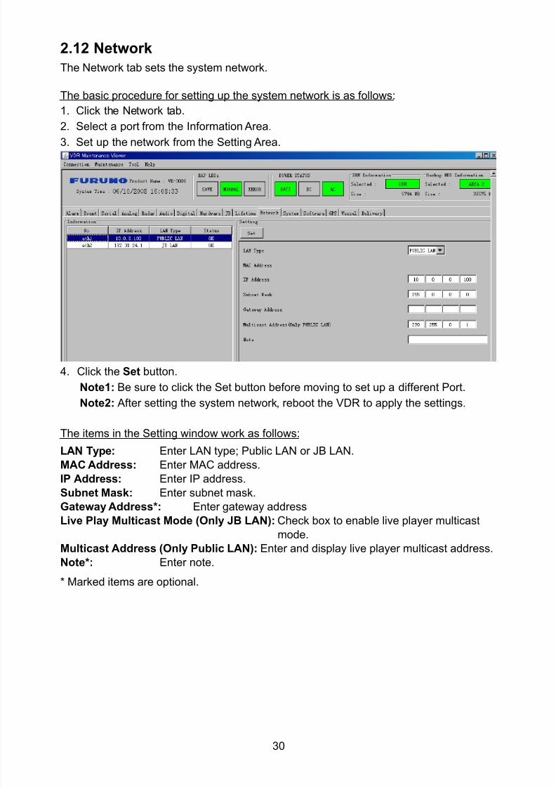
8102019 Ome44376d Vr3000 Mainte Cof26amp3bmol
httpslidepdfcomreaderfullome44376d-vr3000-mainte-cof26amp3bmol 3257
30
212 Network
The Network tab sets the system network
The basic procedure for setting up the system network is as follows
1 Click the Network tab
2 Select a port from the Information Area
3 Set up the network from the Setting Area
4 Click the Set button
Note1 Be sure to click the Set button before moving to set up a different Port
Note2 After setting the system network reboot the VDR to apply the settings
The items in the Setting window work as follows
LAN Type Enter LAN type Public LAN or JB LAN
MAC Address Enter MAC address
IP Address Enter IP address
Subnet Mask Enter subnet mask
Gateway Address Enter gateway address
Live Play Multicast Mode (Only JB LAN) Check box to enable live player multicast
mode
Multicast Address (Only Public LAN) Enter and display live player multicast addressNote Enter note
Marked items are optional
8102019 Ome44376d Vr3000 Mainte Cof26amp3bmol
httpslidepdfcomreaderfullome44376d-vr3000-mainte-cof26amp3bmol 3357
31
213 System
The System tab sets system related functions
The basic procedure for using the System tab is as follows
1 Click the System tab
2 Set up the chosen item from the Setting Area
3 Click the Set button
Note Be sure to click the Set button before moving to a different tab
The items in the Setting window work as follows
VDR Type Enter type of VDR
VDR Model Enter model number of VDR
Radar Interface Check Enable and disable checking of the Radar Interface board
Junction Box Count Enter number of junction boxes in system
DRU Flash Count Enter number of DRU flash disks in system Set 1 when DRU
serial no is 5000 and more Set 3 when DRU serial no is less
than 5000
DRU Capacity Display capacity of DRU
Backup HDD Capacity Display capacity of Backup HDD
VDR Config Version Display version no of VDR
VDR Config Date Display the number of hours the VDR settings have
been saved
VDR Config Code Display configuration identity code
Installation Engineer Enter name of the equipment installer
Installation Company Enter name of installers company
8102019 Ome44376d Vr3000 Mainte Cof26amp3bmol
httpslidepdfcomreaderfullome44376d-vr3000-mainte-cof26amp3bmol 3457
32
Installation Date Enter the date of the installation
MIC Test Time Enter the date of the MIC test
Note Enter note Marked items are optional
USB memory logging Do not check Enable
IEEE1394 BUS Error Auto Restart function Not used
IEEE1394 Active Node Count Do not change the default value of 3 (However set to 5
for serial number 5000 or less of DRU)
IEEE1394 Recover Process Limit Count Do not change the default value of 10
DRU Error Auto Restart function Not used
REBOOT DELAY TIME (sec) Do not change the default value of 10
LIMIT REBOOT COUNT Do not change the default value of 10
Live Player Max Connection Count The max number of Live Player V4 that can be
connected simultaneously The default no is two
but a maximum of five can be set here After you
change this option reboot the VDR to apply the
setting Disconnect the cable connected with
Live Player V4 (PC) from the VDR and thenreconnect it
214 Software
The Software tab sets and display software-related operations
The basic procedure for using the Software tab is as follows
1 Click the Software tab
2 Set up the chosen Item from the Setting Area
3 Click the Set button
8102019 Ome44376d Vr3000 Mainte Cof26amp3bmol
httpslidepdfcomreaderfullome44376d-vr3000-mainte-cof26amp3bmol 3557
33
The items in the Setting window work as follows
VDR System Program Display the VDR system program no
Process Version Display the process version
Power Distribution Unit (PDU) Display the version no of the PDU
Operation System Display the version no of the OS
Audio Driver Display the version no of the audio driverRAP Version Enter the version no of the RAP
AP Version Enter the version no of the AP
JB1-8 Boot Program Display the no of the RJB Boot program for Junction Boxes
1 to 8
JB1-8 App Program Display the no of the RJB App program for Junction Boxes
1 to 8
Watch Dog Interval Do not change the default value of 60 (Enter the process
response time A process is repeated if there is no response
within the time interval set here)
Giveup Interval Do not change the default value of 300 (Enter the restart
watch time The restarting of a process is stopped when the
number of times it has been restarted is exceeded within the
interval set here)
Refork Limit Do not change the default value of 10 (Enter the upper limit
for process restart The restarting of a process is stopped
when the number of times it has been restarted exceeds the
Give up Interval)
Note Enter note
Marked Items are optional
8102019 Ome44376d Vr3000 Mainte Cof26amp3bmol
httpslidepdfcomreaderfullome44376d-vr3000-mainte-cof26amp3bmol 3657
34
215 GPS
The GPS tab sets GPS-related parameters
The basic procedure for using the GPS tab is as follows
1 Click the GPS tab
2 Set up the chosen channel from the Information window3 Set up the chosen item in the Setting Area
4 Click the Set button
5 Repeat steps 2-4 to set up each Channel
6 Click the Check button to perform an inspection on all channels In the Information Area check column either OK or NG (No Good) is displayed
The items in the Setting window work as follows
Priority Display priority order
Date and Time SourceShip Position Source Set GPS source channel (serial channel
number for ZDA sentence)
Check Enable and disable checking
GPS Antenna Position From Bow Enter position of GPS antenna from bow
GPS Antenna Position From Stern Enter position of GPS antenna from stern
GPS Antenna Position From Port Enter position of GPS antenna from port
GPS Antenna Position From Starboard Enter position of GPS antenna from starboard
GPS Failure Threshold If the ZDA is input within the set time limit
the system restarts synchronized If not
input within the time limit the system restarts
without synchronization
8102019 Ome44376d Vr3000 Mainte Cof26amp3bmol
httpslidepdfcomreaderfullome44376d-vr3000-mainte-cof26amp3bmol 3757
35
GPS Delay Time by Time Sync Enter minimum time delay for time
synchronization Time synchronization is started
only in the time set here
GPS Difference Interval The time set here is added to the GPS time to
synchronize the system time Leave at the default
0 value setting
GPS Sync Giveup Time If the system receives the GPS time within the
time set the system synchronizes with the time
When not receiving a signal the system displays
an ldquoerror 26rdquo message
ZDA Timeout Enter value (seconds) for ZDA timeout (234 error)
from GPS
Note Enter and display note
Marked Items are optional
216 VesselThe Vessel tab sets and displays own ships information such as name and IMO number
The basic procedure for using the Vessel tab is as follows
1 Click the Vessel tab
2 Set up information in the Setting window
3 Click the Set button (Be sure to do this before moving to another port)
4 From the Maintenance menu click VDR Config Management and then Config5 Click the Write buttons to save data to the DRU backup HDD CF
The buttons in the Setting window works as follows
Vessel Name Enter name of vessel
Vessel IMO Number Enter IMO number of vessel
Vessel Flag Enter flag of vessel
Approval of Authority Enter name of approving authority
Note Enter note
Marked items are optional
8102019 Ome44376d Vr3000 Mainte Cof26amp3bmol
httpslidepdfcomreaderfullome44376d-vr3000-mainte-cof26amp3bmol 3857
36
217 Delivery
The Delivery tab functions to transmit data from the VDR to a PC via Ethernet LAN Do
not use this function during live connection
The basic procedure for using the Delivery tab is as follows
1 Click the Delivery tab
2 Click the Add button to show the Delivery Config window
3 Select protocol from the Protocol drop-down box (Unicast or Multicast)
4 Enter IP address in the IP address input box
5 Enter port number in the port number input box
6 Click the tab of the data to send (Analog Digital or Serial)
7 Select the channel of the data to send
8 If Serial was selected at step 6 select applicable data sentence from the Inactivewindow Click the right arrow to move the data sentence to the Active window
9 Click the OK button to close the Delivery Config window
10 The settings are listed in a table in the Delivery window Check the checkbox in the
Active column and then click the Set button
The buttons in the Setting window works as follows
Set Save edited settings
Add Create new delivery settings
Modify Modify selected delivery settings
Delete Delete selected delivery settings
8102019 Ome44376d Vr3000 Mainte Cof26amp3bmol
httpslidepdfcomreaderfullome44376d-vr3000-mainte-cof26amp3bmol 3957
37
3 How to Back up Configuration DataThis chapter shows how to back up configuration data to various storage media
Configuration data can be opened with Word Pad or any text editor other than Notepad
31 How to Back up Configuration Data to the Startup CompactFlash (CF)
Back up data to the startup CF after setting the VDR Configuration data is created on the
CF as a configini file
Note When the error shown below occurs during the downloading or uploading of
configuration data check the connection of the DRU Backup HDD and CF and then
upload or download the configuration data again
[CONN] Download failed
[CONN] Could not upload config file
If error occurs again re-install the VDR Maintenance Viewer
Do the following to back up data to a CF
1 Set up parameters on the tabs referring to Chapter 2
2 Click the Maintenance menu
3 Select VDR Config Management
4 Click the Upload button
5 A confirmation box appears click the OK button to start uploading to the VDR
6 Click the Write button where the arrow connects between VDR and DRU BackupHDD
7 A confirmation window appears click the OK button to save the configuration data tothe DRU and Backup HDD
8102019 Ome44376d Vr3000 Mainte Cof26amp3bmol
httpslidepdfcomreaderfullome44376d-vr3000-mainte-cof26amp3bmol 4057
38
8 Click the Write button where the arrow connects between the VDR and CF
9 A confirmation window appears click the OK button to save the configuration data tothe startup CF
10 Check that the PC VDR DRU Backup HDD and CF share the same VDR configcode
32 How to Back up Configuration Data to a PC
Configuration data saved to the PC can be edited with Wordpad and shared with other
vessels For future service ease it is recommended to backup configuration data to the
PC and have the data on board the vessel Also it is recommended to upload this data to
Furuno SMS (Service Management System) If unable to upload to Furuno SMS please
contact the Service Center Furuno Japan
To back up configuration data to the PC do as follows
1 Set up parameters on the tabs referring to Chapter 2
2 Click the Maintenance menu
3 Select VDR Config Management
4 Click the Export to button
5 A confirmation window appears click the OK button
6 Select where to save the data enter file name then click the Open button
7 Confirm that back up file is in the location selected
33 How to restore the default settings
Click the Default button on the VDR Config Management window to restore the default
settings of the DRU Backup HDD CF and VDR Maintenance Viewer
8102019 Ome44376d Vr3000 Mainte Cof26amp3bmol
httpslidepdfcomreaderfullome44376d-vr3000-mainte-cof26amp3bmol 4157
39
4 How to Upload Configuration Datafrom a PCThe procedure below shows how to upload configuration from the PC to aVR-3000VR-3000S
1 Click the Maintenance menu
2 Select VDR Config Management
3 Click the Import from button
4 The Open window appears Select configuration data and then click the Open button
5 Click the Upload button to upload data to the VR-3000VR-3000S
6 Click the Write buttons to save data to the DRU backup HDD and CF
8102019 Ome44376d Vr3000 Mainte Cof26amp3bmol
httpslidepdfcomreaderfullome44376d-vr3000-mainte-cof26amp3bmol 4257
40
5 Media ManagementThe media management feature deletes data from recording media initialization the
system etc There are two method LAN connection and Direct connection The Direct
connection takes longer time than the LAN connection Basically use the LAN connection
method
Note Initialization or creation of recording media is not available when Source Select onthe Live Player V4 is selected to Backup HDD
51 Initialization
This section shows how to delete data from the recording media Configuration data is
not deleted After performing the software configuration delete the data from the DRU
and HDD
Do the following to delete data from the DRU (LAN connection)
1 Set the PlaybackCPU switch in the DCU to the CPU position
2 Use an Ethernet cross cable to connect the PC to J14 (DATA) in the DCU (See page5)
3 Open the Tool menu
4 Select Media Management to open the VDR Media Management window
5 Check that IP address shown in the ldquoLAN Connect to IPrdquo in VDR Media Table Area isthe same as the IP address access point
6 Select ldquoLAN Connect to IPrdquo in the VDR Media Table column
8102019 Ome44376d Vr3000 Mainte Cof26amp3bmol
httpslidepdfcomreaderfullome44376d-vr3000-mainte-cof26amp3bmol 4357
41
7 Click the Analyze button A list of recording media connected to the VDR appears
Put a checkmark in the checkbox of the Select column for the DRU in the Name columnNote If there are several flash memories in the DRU all flash memories are shownCheck all flash memories shown
8 Select ldquoDRU Initializerdquo from the Operation dropdown list in the Operation area
10 Click the Run button
Do the following to delete data from the DRU (Direct connection)
1 Start Live Player V4 software
2 Open the Tool menu and select Source Select Select Live from the pull-downmenu
3 Click the Alarm tab and open Alarm History
4 Set the PlaybackCPU switch in the DCU to the Playback position
5 Wait approx 10 minutes and confirm that Alarm 174 occurs on Alarm History of LivePlayer V4
6 Connect an IEEEE1394 cable between J6 in the DCU and the PC
7 Open the Tool menu
8 Select Media Management to show the VDR Media Management window
9 Select Direct in the VDR Media Table column
10 Click the Analyze button A list of recording media connected to the VDR appears
11 Put a checkmark in the checkbox of the Select column for the DRU in the Namecolumn
Note If there are several flash memories in the DRU all flash memories are shownCheck all flash memories shown
12 Select ldquoDRU Initializerdquo from the Operation dropdown list in the Operation area
13 Enter password in the password column
14 Click the RUN button
8102019 Ome44376d Vr3000 Mainte Cof26amp3bmol
httpslidepdfcomreaderfullome44376d-vr3000-mainte-cof26amp3bmol 4457
42
Delete data from the Backup HDD as follows (LAN connection)
1 Set the PlaybackCPU switch in the DCU to the CPU position
2 Check that an Ethernet cross cable is connected between J14 in the DCU and the PC
3 Open the Tool menu
4 Select Media Management to open the VDR Media Management window
5 Check that IP address shown in the LAN Connect to IP in VDR Media Table Area is
the same as the IP address access point6 Select LAN Connect to IP in the VDR Media Table column
7 Click the Analyze button
8 A list of recording media connected to the VDR appears
9 Put a checkmark in the box of the Select column for the Backup HDD in the Namecolumn Select ldquoBackup HDD Initializerdquo from the Operation dropdown list in theOperation area
10 Click the Run button
Delete data from the Backup HDD as follows (Direct connection)
1 Start Live Player V4 software
2 Open the Tool menu and select Source Select Select Live from the pull-downmenu
3 Click the Alarm tab and open Alarm History
4 Set the PlaybackCPU switch in the DCU to the Playback position
5 Wait approx 10 minutes and confirm that Alarm 174 occurs on Alarm History of LivePlayer V4
6 Connect an IEEE1394 cable between J6 in the DCU and the PC
7 Open the Tool menu
8 Select Media Management to open the VDR Media Management window9 Select Direct in the VDR Media Table window
10 Click the Analyze button A list of recording media connected to the VDR appears
11 Put a checkmark in the check box of the Select column for the Backup HDD in theName column Select ldquoBackup HDD Initializerdquo from the Operation dropdown list in theOperation area
12 Enter password
13 Click the Run button
8102019 Ome44376d Vr3000 Mainte Cof26amp3bmol
httpslidepdfcomreaderfullome44376d-vr3000-mainte-cof26amp3bmol 4557
43
52 CreationThe Creation feature initializes recording media
Note1 This feature deletes ALL configuration data Backup all VDR configuration data
Note2 When you initialize medium that is a different format for the DRU or Backup HDDdelete all partitions with the disk management tool of Windows
Note3 When the Creation is failed try again If you can not initialize recording media tryunder condition as shown below
Do the Creation by the direct connection (When the Creation by the LAN
connection is failed)
Delete all partitions of the DRU or Backup HDD with the disk management tool of
Windows to do the Creation
If the Creation is still failed request service to repairreplace the DRU or Backup
HDD
Initialize the DRU as follows (LAN connection)
1 Set the PlaybackCPU switch in the DCU to the CPU position
2 Check that an Ethernet cross cable is connected between J14 in the DCU and the PC
3 Open the Tool menu
4 Select Media Management to open the VDR Media Management window
5 Check that IP address shown in the LAN Connect to IP in VDR Media Table Area isthe same as the IP address access point
6 Check ldquoLAN Connect to IPrdquo in the VDR Media Table column
7 Click the Analyze button A list of recording media connected to the VDR appears
8 Put a checkmark in the box of the Select column for the DRU in the Name column
Select ldquoDRU Creationrdquo from the Operation dropdown list in the Operation area
9 Click the Run button
Initialize the Backup HDD as follows (LAN connection)
1 To format the Backup HDD place a checkmark in the Select column of the listedrecord media in the Name column of the VDR Media Management dialogue box
2 From the Operation drop down list of the Operation area select ldquoBackup HDDCreation (Radar) or ldquoBackup HDD Creationrdquo
Two partition tools are available for the Backup HDD in the Media Management as
below
Backup HDD creation
This tool is used when the number of the SXGA video signal connected to the BackupHDD is the same as the DRU The same partition is created on both DRU and HDD
(1) When two SXGA video signals are recorded onto the HDD while 9-GB DRU isconnected
(2) When an SXGA video signal is recorded onto the HDD while 6-GB DRU isconnected
Backup HDD creation (radar)
This tool is used when two SXGA video signals are recorded onto the HDD with 6-GB
DRU connected The HDD has an area (radar) to record the second radar signal inaddition to the same partition as the DRU This tool cannot be used when 9-GB DRUis connected
3 Press the Run Button
8102019 Ome44376d Vr3000 Mainte Cof26amp3bmol
httpslidepdfcomreaderfullome44376d-vr3000-mainte-cof26amp3bmol 4657
44
Initialize the DRU as follows (Direct connection)
1 Start Live Player V4 software
2 Open the Tool menu and select Source Select Select Live from the pull-downmenu
3 Click the Alarm tab and open Alarm History
4 Set the PlaybackCPU switch in the DCU to the Playback position
5 Wait approx 10 minutes and confirm that Alarm 174 occurs on Alarm History of LivePlayer V4
6 Connect an IEEE1394 cable between J6 in the DCU and the PC
7 Open the Tool menu
8 Select Media Management to open the VDR Media Management window
9 Select Direct in the VDR Media Table window
10 Click the Analyze button A list of recording media connected to the VDR appears
11 Put a checkmark in the box of the Select column for the DRU and the desiredrecording media in the Name column In the Operation dropdown list of the Operationarea select ldquoDRU Creationrdquo
12 Enter password in the password column
13 Click the Run button
Initialize the Backup HDD as follows (Direct Connection)
1 To format the Backup HDD place a checkmark in the Select column of the listedrecord media in the Name column of the VDR Media Management dialogue box
2 From the Operation column of the Operation area select ldquoBackup HDD Creation(Radar) or ldquoBackup HDD Creationrdquo
Backup HDD creation
This tool is used when the number of the SXGA video signal connected to the BackupHDD is the same as the DRU The same partition is created on both DRU and HDD
(1) When two SXGA video signals are recorded onto the HDD while 9-GB DRU is
connected
(2) When an SXGA video signal is recorded onto the HDD while 6-GB DRU is
connected
Backup HDD creation (radar)
This tool is used when two SXGA video signals are recorded onto the HDD with 6-GBDRU connected The HDD has an area (radar) to record the second radar signal inaddition to the same partition as the DRU This tool cannot be used when 9-GB DRUis connected
3 Enter the password in the Password column
4 Press the Run Button
8102019 Ome44376d Vr3000 Mainte Cof26amp3bmol
httpslidepdfcomreaderfullome44376d-vr3000-mainte-cof26amp3bmol 4757
45
53 How to Enable Recording Area on the Backup HDD
This function enables writing over a recording area To prevent falsification of data all
recording areas must be saved otherwise this function is disabled To use this function push
the SAVE button Save the data before doing this procedure
Note Software version 135 or higher can enable writing over a recording area even if
all recording areas are not saved
Recording enable (LAN connection)
1 Set the PlaybackCPU switch in the DCU to the CPU position
2 Check that an Ethernet cross cable is connected between J14 in the DCU and the PC
3 Open the Tool menu
4 Select Media Management to open the VDR Media Management window
5 Check that IP address shown in the ldquoLAN Connect to IPrdquo in VDR Media Table Area isthe same as the IP address access point
6 Select ldquoLAN Connect to IPrdquo in the VDR Media Table column7 Click the Analyze button A list of recording media connected to the VDR appears
8 Put a checkmark in the box of the Select column for the Backup HDD in the Namecolumn
9 Select ldquoBackup HDD Recording Area Enablerdquo from the Operation dropdown list in theOperation area
10 Click the Run button
Recording enable (Direct connection)
1 Start Live Player V4 software
2 Open the Tool menu and select Source Select Select Live from the pull-down menu3 Click the Alarm tab and open Alarm History
4 Set the PlaybackCPU switch in the DCU to the Playback position
5 Wait approx 10 minutes and confirm that Alarm 174 occurs on Alarm History of LivePlayer V4
6 Connect an IEEE1394 cable between J6 in the DCU and the PC
7 Open the Tool menu
8 Select Media Management to open the VDR Media Management window
9 Select Direct in the VDR Media Table window
10 Click the Analyze button A list of recording media connected to the VDR appears11 Put a checkmark in the box of the Select column for the Backup HDD in the Name
column
12 Select ldquoBackup HDD Recording Area Enablerdquo from the Operation dropdown list in theOperation area
13 Enter password
14 Click the Run button
8102019 Ome44376d Vr3000 Mainte Cof26amp3bmol
httpslidepdfcomreaderfullome44376d-vr3000-mainte-cof26amp3bmol 4857
46
6 Other Functions
61 Software Management
The software download feature downloads VDR system software to the PC
To download software
1 Click the Maintenance menu
2 From the Software Management menu click Software Download to show theSoftware Download window
3 Enter the IP address 1000100 in the IP address box in the Update Server area
4 Click the Download Software button
5 The confirmation window appears click the OK button
The Software Backup Execute window shows the results of the download
Software is downloaded to C Program Files VDR Viewer Viewer Backup The software file
name is vdrtar
To Update Software
VDR system program version 16x can update the software with the procedure shownbelow
Note Do not update the file downloaded in procedures above
1 Click the Maintenance menu
2 From the Software Management menu click Software Upload to show the SoftwareUpload area
3 Click the Select button to show the Open window
4 Select update file (vdrtar) and click the Open button
8102019 Ome44376d Vr3000 Mainte Cof26amp3bmol
httpslidepdfcomreaderfullome44376d-vr3000-mainte-cof26amp3bmol 4957
47
5 Check the displayed Software information is correct
6 Enter the IP address 1000100 in the IP address box in the Update Server area
7 Enter password
8 Click the Update button
After the updating is completed the VDR is automatically restarted
Note Click the Restore button on the Software Update window to restore previoussoftware version This feature is available after updating the software
62 Password Management
The password can be changed for a serviceman to access the equipment Contact
FURUNO to get the default password to use during installation
Serviceman password
1 Click the Maintenance menu2 Select Change Serviceman Password from Password Management to show the
Change Serviceman Password window
3 Enter current password in the Old Password box
4 Enter the new password in the New Password box of the Change Password area
5 Enter new password again in the Confirm New Password box
6 Click the OK button
Audio password
The audio password set at the VDR Maintenance Viewer can be removed to enable
audio access without password1 Click the Maintenance menu
2 Select Change Audio Password from Password Management to show the Change Audio Password window
3 The confirmation window appears click the OK button
8102019 Ome44376d Vr3000 Mainte Cof26amp3bmol
httpslidepdfcomreaderfullome44376d-vr3000-mainte-cof26amp3bmol 5057
48
63 Record ComparisonThe integrity of the DRU and Backup HDD recordings can be compared This function isused by the RampD engineer for debugging
Follow the procedure as shown below
1 Click the Maintenance menu2 Select Record Comparison to show the Record Comparison window
The results are shown every 15 seconds in the Record Comparison window
8102019 Ome44376d Vr3000 Mainte Cof26amp3bmol
httpslidepdfcomreaderfullome44376d-vr3000-mainte-cof26amp3bmol 5157
49
64 Software History
This section shows you to save and configure software history (communications record)
How to save software history
Note When the error dialog appears while saving the software history restart the VDR
Maintenance Viewer
1 Click the Maintenance menu
2 Select Software History Collect
3 Click the Select button The Open dialog box appears
4 Select where to save the data then click the Open button
5 Select desired save condition then click the OK buttonNone No savingAt Once Save the software history manually Saving begins as soon as the OK button is clickedPeriodic For debugging Do not use otherwise The intervals are 30 sec 60 secand 120 secAlarm Detection For debugging Do not use otherwise Software history is savedwhen specified alarm is released Enter alarm number
How to configure software communications record
The RampD engineer uses this function for debugging Do not do this procedure unless
required Malfunction can result
1 Click the Maintenance menu
2 Select Software History Config
3 Do the followingProcess Select the type of communications record to save ALL saves allcommunications records
Detail Hide or show detailed information4 Click the Send button
8102019 Ome44376d Vr3000 Mainte Cof26amp3bmol
httpslidepdfcomreaderfullome44376d-vr3000-mainte-cof26amp3bmol 5257
50
65 Easy SetupThis feature sets equipment settings in batch and creates a data file of those settings
Default template The default template is created with the settings entered at installation
1 Click the Maintenance menu
2 Select Easy Setup to show the Template Selection window
3 Select Default Template
4 Click the Start button to show the Easy Setup window
5 Right click the channels (Radar Audio Digital Serial Analog) then select Edit toshow the Equipment Selection window
6 From the Equipment Directory window select equipment connected to the selectedchannel and then click the OK button
7 Repeat steps 5 and 6 to select equipment settings for each channel
8 Click the Save button in the Easy Setup window to show the Save window
9 Select where to save the file and enter file name
10 Click the Save button
8102019 Ome44376d Vr3000 Mainte Cof26amp3bmol
httpslidepdfcomreaderfullome44376d-vr3000-mainte-cof26amp3bmol 5357
51
Specific template Use a file already created
1 Click the Maintenance menu
2 Select Easy Setup to show the Template Selection window
3 Check Specified Template
4 Click the Select button and then select the file to edit
5 Click the Start button to show the Easy Setup window
6 Right click the channels (Radar Audio Digital Serial Analog) then select Edit toshow the Equipment Selection window
7 From the Equipment Directory window select equipment connected to the selectedchannel and then click the OK button
8 Repeat steps 6 and 7 to select equipment settings for each channel
9 Click the Save button in the Easy Setup window to show the Save window
10Select where to save the file and enter file name
11 Click the Save button
66 Equipment Management
This feature controls the import and export of equipment settings
Import data file
Import data files of equipment settings created in Easy Setup etc to the VDR
1 Click the Maintenance menu
2 Select Import from Equipment Management to show the Open window
3 Select the data file to import and click Open
Export data file
Export data files of equipment settings from the VDR to a PC
1 Click the Maintenance menu
2 Select Export from Equipment Management to show the Save window
3 Enter file name
4 Click the Save button
8102019 Ome44376d Vr3000 Mainte Cof26amp3bmol
httpslidepdfcomreaderfullome44376d-vr3000-mainte-cof26amp3bmol 5457
52
67 PC_RAP
This feature enables the same operation of the RAP (Remote Alarm Panel) from a PC
Select PC_RAP from the Tool menu to show the PC_RAP window
The buttons in the PC_RAP window function as shown below
SAVE Stop recording in the area where recording is currently being done
ACK Silence audio alarm
The PC_RAP display shows the following information with LEDs
RAP_LEDs Display the status of LEDs on the RAPSave The Save button blinks yellow when pushed When the 4 memory
areas have data recorded to them the Save button lights orange when
pushed
Normal Lights (green) where there are no unconfirmed or not restored
alarms
Error Flashes (red) for not confirmed alarm Lights (red) for unrestored
alarm
8102019 Ome44376d Vr3000 Mainte Cof26amp3bmol
httpslidepdfcomreaderfullome44376d-vr3000-mainte-cof26amp3bmol 5557
53
Backup HDD Information Display status of backup HDD
Selected Display current recording area and its status in green for
normal operation and in red for abnormal operation
Size Display capacity of backup HDD
Alarm area displays unconfirmed alarms
Time Display time alarm was generatedNumber Display number of alarm
Name Display name of alarm
Pending Alarm displays the unrestored alarms out of confirmed alarms only
Time Display time alarm was generated
Number Display number of alarm
Name Display name of alarm
8102019 Ome44376d Vr3000 Mainte Cof26amp3bmol
httpslidepdfcomreaderfullome44376d-vr3000-mainte-cof26amp3bmol 5657
54
68 Other
Status Monitor
The status monitor feature provides comprehensive data about the status of the VDR
From the menu bar click Toolgt Status Monitor to show the Status Monitor window
The buttons in the Status Monitor window work as shown below
Reload Settings for automatic refreshing of the status monitor
ON Turn automatic refresh OFF
OFF The Status Monitor is refreshed every five seconds
Save Available when Reload ON is selected The contents of the Status Monitor can be
saved to a text fileUpdate Update the Status Monitor display
Close Close the Status Monitor display
8102019 Ome44376d Vr3000 Mainte Cof26amp3bmol
httpslidepdfcomreaderfullome44376d-vr3000-mainte-cof26amp3bmol 5757
VDR Error List
This feature compiles all the errors shown on the RAP for easy reference
Access from MenugtToolgtVDR Error List
The VDR error list contains the following information
NO Display the number of the error
Title Display the name of the error
Detail Display details about the error
Exchange Check
This feature removes the alarms generated when replacing the DRU or backup HDD
Access MenugtToolgtExchange Check select either DRU or Backup HDD and click OK
Reboot
Reboot the VDR
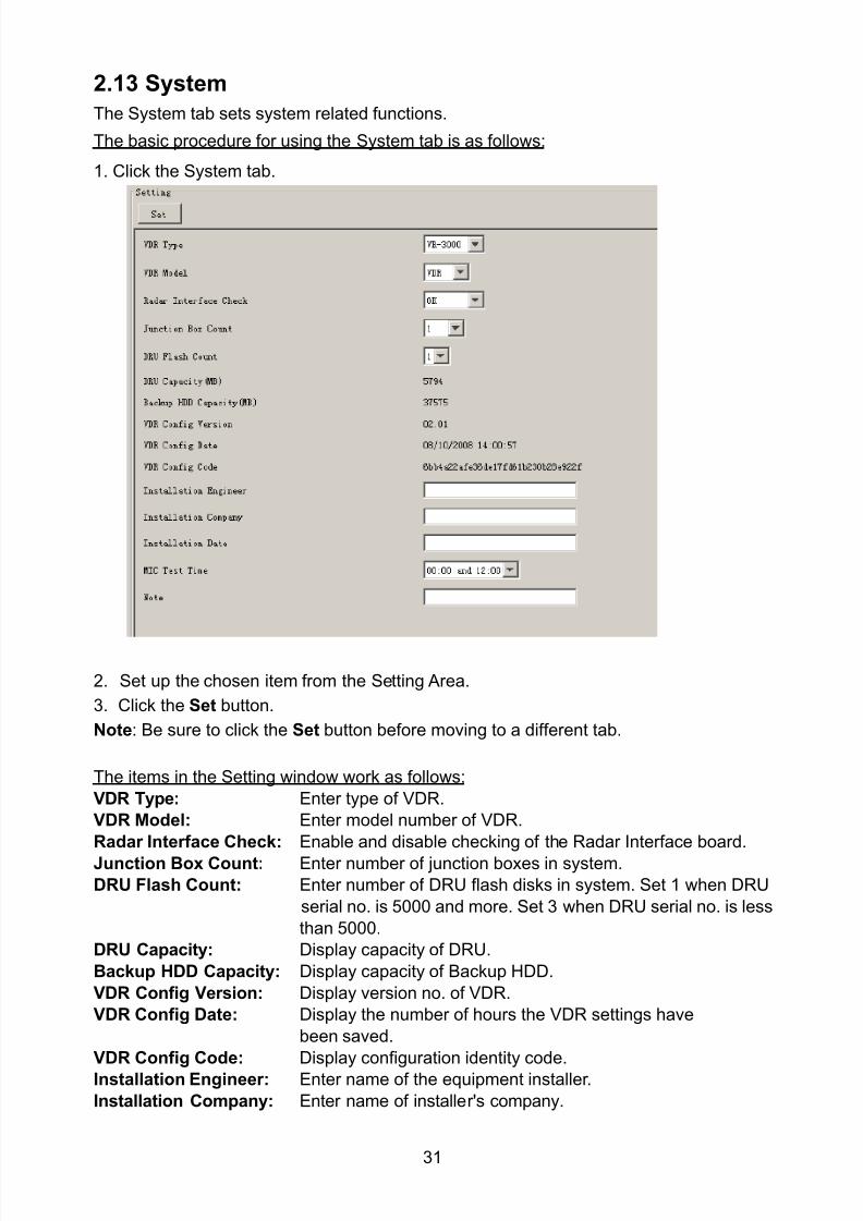
8102019 Ome44376d Vr3000 Mainte Cof26amp3bmol
httpslidepdfcomreaderfullome44376d-vr3000-mainte-cof26amp3bmol 3357
31
213 System
The System tab sets system related functions
The basic procedure for using the System tab is as follows
1 Click the System tab
2 Set up the chosen item from the Setting Area
3 Click the Set button
Note Be sure to click the Set button before moving to a different tab
The items in the Setting window work as follows
VDR Type Enter type of VDR
VDR Model Enter model number of VDR
Radar Interface Check Enable and disable checking of the Radar Interface board
Junction Box Count Enter number of junction boxes in system
DRU Flash Count Enter number of DRU flash disks in system Set 1 when DRU
serial no is 5000 and more Set 3 when DRU serial no is less
than 5000
DRU Capacity Display capacity of DRU
Backup HDD Capacity Display capacity of Backup HDD
VDR Config Version Display version no of VDR
VDR Config Date Display the number of hours the VDR settings have
been saved
VDR Config Code Display configuration identity code
Installation Engineer Enter name of the equipment installer
Installation Company Enter name of installers company
8102019 Ome44376d Vr3000 Mainte Cof26amp3bmol
httpslidepdfcomreaderfullome44376d-vr3000-mainte-cof26amp3bmol 3457
32
Installation Date Enter the date of the installation
MIC Test Time Enter the date of the MIC test
Note Enter note Marked items are optional
USB memory logging Do not check Enable
IEEE1394 BUS Error Auto Restart function Not used
IEEE1394 Active Node Count Do not change the default value of 3 (However set to 5
for serial number 5000 or less of DRU)
IEEE1394 Recover Process Limit Count Do not change the default value of 10
DRU Error Auto Restart function Not used
REBOOT DELAY TIME (sec) Do not change the default value of 10
LIMIT REBOOT COUNT Do not change the default value of 10
Live Player Max Connection Count The max number of Live Player V4 that can be
connected simultaneously The default no is two
but a maximum of five can be set here After you
change this option reboot the VDR to apply the
setting Disconnect the cable connected with
Live Player V4 (PC) from the VDR and thenreconnect it
214 Software
The Software tab sets and display software-related operations
The basic procedure for using the Software tab is as follows
1 Click the Software tab
2 Set up the chosen Item from the Setting Area
3 Click the Set button
8102019 Ome44376d Vr3000 Mainte Cof26amp3bmol
httpslidepdfcomreaderfullome44376d-vr3000-mainte-cof26amp3bmol 3557
33
The items in the Setting window work as follows
VDR System Program Display the VDR system program no
Process Version Display the process version
Power Distribution Unit (PDU) Display the version no of the PDU
Operation System Display the version no of the OS
Audio Driver Display the version no of the audio driverRAP Version Enter the version no of the RAP
AP Version Enter the version no of the AP
JB1-8 Boot Program Display the no of the RJB Boot program for Junction Boxes
1 to 8
JB1-8 App Program Display the no of the RJB App program for Junction Boxes
1 to 8
Watch Dog Interval Do not change the default value of 60 (Enter the process
response time A process is repeated if there is no response
within the time interval set here)
Giveup Interval Do not change the default value of 300 (Enter the restart
watch time The restarting of a process is stopped when the
number of times it has been restarted is exceeded within the
interval set here)
Refork Limit Do not change the default value of 10 (Enter the upper limit
for process restart The restarting of a process is stopped
when the number of times it has been restarted exceeds the
Give up Interval)
Note Enter note
Marked Items are optional
8102019 Ome44376d Vr3000 Mainte Cof26amp3bmol
httpslidepdfcomreaderfullome44376d-vr3000-mainte-cof26amp3bmol 3657
34
215 GPS
The GPS tab sets GPS-related parameters
The basic procedure for using the GPS tab is as follows
1 Click the GPS tab
2 Set up the chosen channel from the Information window3 Set up the chosen item in the Setting Area
4 Click the Set button
5 Repeat steps 2-4 to set up each Channel
6 Click the Check button to perform an inspection on all channels In the Information Area check column either OK or NG (No Good) is displayed
The items in the Setting window work as follows
Priority Display priority order
Date and Time SourceShip Position Source Set GPS source channel (serial channel
number for ZDA sentence)
Check Enable and disable checking
GPS Antenna Position From Bow Enter position of GPS antenna from bow
GPS Antenna Position From Stern Enter position of GPS antenna from stern
GPS Antenna Position From Port Enter position of GPS antenna from port
GPS Antenna Position From Starboard Enter position of GPS antenna from starboard
GPS Failure Threshold If the ZDA is input within the set time limit
the system restarts synchronized If not
input within the time limit the system restarts
without synchronization
8102019 Ome44376d Vr3000 Mainte Cof26amp3bmol
httpslidepdfcomreaderfullome44376d-vr3000-mainte-cof26amp3bmol 3757
35
GPS Delay Time by Time Sync Enter minimum time delay for time
synchronization Time synchronization is started
only in the time set here
GPS Difference Interval The time set here is added to the GPS time to
synchronize the system time Leave at the default
0 value setting
GPS Sync Giveup Time If the system receives the GPS time within the
time set the system synchronizes with the time
When not receiving a signal the system displays
an ldquoerror 26rdquo message
ZDA Timeout Enter value (seconds) for ZDA timeout (234 error)
from GPS
Note Enter and display note
Marked Items are optional
216 VesselThe Vessel tab sets and displays own ships information such as name and IMO number
The basic procedure for using the Vessel tab is as follows
1 Click the Vessel tab
2 Set up information in the Setting window
3 Click the Set button (Be sure to do this before moving to another port)
4 From the Maintenance menu click VDR Config Management and then Config5 Click the Write buttons to save data to the DRU backup HDD CF
The buttons in the Setting window works as follows
Vessel Name Enter name of vessel
Vessel IMO Number Enter IMO number of vessel
Vessel Flag Enter flag of vessel
Approval of Authority Enter name of approving authority
Note Enter note
Marked items are optional
8102019 Ome44376d Vr3000 Mainte Cof26amp3bmol
httpslidepdfcomreaderfullome44376d-vr3000-mainte-cof26amp3bmol 3857
36
217 Delivery
The Delivery tab functions to transmit data from the VDR to a PC via Ethernet LAN Do
not use this function during live connection
The basic procedure for using the Delivery tab is as follows
1 Click the Delivery tab
2 Click the Add button to show the Delivery Config window
3 Select protocol from the Protocol drop-down box (Unicast or Multicast)
4 Enter IP address in the IP address input box
5 Enter port number in the port number input box
6 Click the tab of the data to send (Analog Digital or Serial)
7 Select the channel of the data to send
8 If Serial was selected at step 6 select applicable data sentence from the Inactivewindow Click the right arrow to move the data sentence to the Active window
9 Click the OK button to close the Delivery Config window
10 The settings are listed in a table in the Delivery window Check the checkbox in the
Active column and then click the Set button
The buttons in the Setting window works as follows
Set Save edited settings
Add Create new delivery settings
Modify Modify selected delivery settings
Delete Delete selected delivery settings
8102019 Ome44376d Vr3000 Mainte Cof26amp3bmol
httpslidepdfcomreaderfullome44376d-vr3000-mainte-cof26amp3bmol 3957
37
3 How to Back up Configuration DataThis chapter shows how to back up configuration data to various storage media
Configuration data can be opened with Word Pad or any text editor other than Notepad
31 How to Back up Configuration Data to the Startup CompactFlash (CF)
Back up data to the startup CF after setting the VDR Configuration data is created on the
CF as a configini file
Note When the error shown below occurs during the downloading or uploading of
configuration data check the connection of the DRU Backup HDD and CF and then
upload or download the configuration data again
[CONN] Download failed
[CONN] Could not upload config file
If error occurs again re-install the VDR Maintenance Viewer
Do the following to back up data to a CF
1 Set up parameters on the tabs referring to Chapter 2
2 Click the Maintenance menu
3 Select VDR Config Management
4 Click the Upload button
5 A confirmation box appears click the OK button to start uploading to the VDR
6 Click the Write button where the arrow connects between VDR and DRU BackupHDD
7 A confirmation window appears click the OK button to save the configuration data tothe DRU and Backup HDD
8102019 Ome44376d Vr3000 Mainte Cof26amp3bmol
httpslidepdfcomreaderfullome44376d-vr3000-mainte-cof26amp3bmol 4057
38
8 Click the Write button where the arrow connects between the VDR and CF
9 A confirmation window appears click the OK button to save the configuration data tothe startup CF
10 Check that the PC VDR DRU Backup HDD and CF share the same VDR configcode
32 How to Back up Configuration Data to a PC
Configuration data saved to the PC can be edited with Wordpad and shared with other
vessels For future service ease it is recommended to backup configuration data to the
PC and have the data on board the vessel Also it is recommended to upload this data to
Furuno SMS (Service Management System) If unable to upload to Furuno SMS please
contact the Service Center Furuno Japan
To back up configuration data to the PC do as follows
1 Set up parameters on the tabs referring to Chapter 2
2 Click the Maintenance menu
3 Select VDR Config Management
4 Click the Export to button
5 A confirmation window appears click the OK button
6 Select where to save the data enter file name then click the Open button
7 Confirm that back up file is in the location selected
33 How to restore the default settings
Click the Default button on the VDR Config Management window to restore the default
settings of the DRU Backup HDD CF and VDR Maintenance Viewer
8102019 Ome44376d Vr3000 Mainte Cof26amp3bmol
httpslidepdfcomreaderfullome44376d-vr3000-mainte-cof26amp3bmol 4157
39
4 How to Upload Configuration Datafrom a PCThe procedure below shows how to upload configuration from the PC to aVR-3000VR-3000S
1 Click the Maintenance menu
2 Select VDR Config Management
3 Click the Import from button
4 The Open window appears Select configuration data and then click the Open button
5 Click the Upload button to upload data to the VR-3000VR-3000S
6 Click the Write buttons to save data to the DRU backup HDD and CF
8102019 Ome44376d Vr3000 Mainte Cof26amp3bmol
httpslidepdfcomreaderfullome44376d-vr3000-mainte-cof26amp3bmol 4257
40
5 Media ManagementThe media management feature deletes data from recording media initialization the
system etc There are two method LAN connection and Direct connection The Direct
connection takes longer time than the LAN connection Basically use the LAN connection
method
Note Initialization or creation of recording media is not available when Source Select onthe Live Player V4 is selected to Backup HDD
51 Initialization
This section shows how to delete data from the recording media Configuration data is
not deleted After performing the software configuration delete the data from the DRU
and HDD
Do the following to delete data from the DRU (LAN connection)
1 Set the PlaybackCPU switch in the DCU to the CPU position
2 Use an Ethernet cross cable to connect the PC to J14 (DATA) in the DCU (See page5)
3 Open the Tool menu
4 Select Media Management to open the VDR Media Management window
5 Check that IP address shown in the ldquoLAN Connect to IPrdquo in VDR Media Table Area isthe same as the IP address access point
6 Select ldquoLAN Connect to IPrdquo in the VDR Media Table column
8102019 Ome44376d Vr3000 Mainte Cof26amp3bmol
httpslidepdfcomreaderfullome44376d-vr3000-mainte-cof26amp3bmol 4357
41
7 Click the Analyze button A list of recording media connected to the VDR appears
Put a checkmark in the checkbox of the Select column for the DRU in the Name columnNote If there are several flash memories in the DRU all flash memories are shownCheck all flash memories shown
8 Select ldquoDRU Initializerdquo from the Operation dropdown list in the Operation area
10 Click the Run button
Do the following to delete data from the DRU (Direct connection)
1 Start Live Player V4 software
2 Open the Tool menu and select Source Select Select Live from the pull-downmenu
3 Click the Alarm tab and open Alarm History
4 Set the PlaybackCPU switch in the DCU to the Playback position
5 Wait approx 10 minutes and confirm that Alarm 174 occurs on Alarm History of LivePlayer V4
6 Connect an IEEEE1394 cable between J6 in the DCU and the PC
7 Open the Tool menu
8 Select Media Management to show the VDR Media Management window
9 Select Direct in the VDR Media Table column
10 Click the Analyze button A list of recording media connected to the VDR appears
11 Put a checkmark in the checkbox of the Select column for the DRU in the Namecolumn
Note If there are several flash memories in the DRU all flash memories are shownCheck all flash memories shown
12 Select ldquoDRU Initializerdquo from the Operation dropdown list in the Operation area
13 Enter password in the password column
14 Click the RUN button
8102019 Ome44376d Vr3000 Mainte Cof26amp3bmol
httpslidepdfcomreaderfullome44376d-vr3000-mainte-cof26amp3bmol 4457
42
Delete data from the Backup HDD as follows (LAN connection)
1 Set the PlaybackCPU switch in the DCU to the CPU position
2 Check that an Ethernet cross cable is connected between J14 in the DCU and the PC
3 Open the Tool menu
4 Select Media Management to open the VDR Media Management window
5 Check that IP address shown in the LAN Connect to IP in VDR Media Table Area is
the same as the IP address access point6 Select LAN Connect to IP in the VDR Media Table column
7 Click the Analyze button
8 A list of recording media connected to the VDR appears
9 Put a checkmark in the box of the Select column for the Backup HDD in the Namecolumn Select ldquoBackup HDD Initializerdquo from the Operation dropdown list in theOperation area
10 Click the Run button
Delete data from the Backup HDD as follows (Direct connection)
1 Start Live Player V4 software
2 Open the Tool menu and select Source Select Select Live from the pull-downmenu
3 Click the Alarm tab and open Alarm History
4 Set the PlaybackCPU switch in the DCU to the Playback position
5 Wait approx 10 minutes and confirm that Alarm 174 occurs on Alarm History of LivePlayer V4
6 Connect an IEEE1394 cable between J6 in the DCU and the PC
7 Open the Tool menu
8 Select Media Management to open the VDR Media Management window9 Select Direct in the VDR Media Table window
10 Click the Analyze button A list of recording media connected to the VDR appears
11 Put a checkmark in the check box of the Select column for the Backup HDD in theName column Select ldquoBackup HDD Initializerdquo from the Operation dropdown list in theOperation area
12 Enter password
13 Click the Run button
8102019 Ome44376d Vr3000 Mainte Cof26amp3bmol
httpslidepdfcomreaderfullome44376d-vr3000-mainte-cof26amp3bmol 4557
43
52 CreationThe Creation feature initializes recording media
Note1 This feature deletes ALL configuration data Backup all VDR configuration data
Note2 When you initialize medium that is a different format for the DRU or Backup HDDdelete all partitions with the disk management tool of Windows
Note3 When the Creation is failed try again If you can not initialize recording media tryunder condition as shown below
Do the Creation by the direct connection (When the Creation by the LAN
connection is failed)
Delete all partitions of the DRU or Backup HDD with the disk management tool of
Windows to do the Creation
If the Creation is still failed request service to repairreplace the DRU or Backup
HDD
Initialize the DRU as follows (LAN connection)
1 Set the PlaybackCPU switch in the DCU to the CPU position
2 Check that an Ethernet cross cable is connected between J14 in the DCU and the PC
3 Open the Tool menu
4 Select Media Management to open the VDR Media Management window
5 Check that IP address shown in the LAN Connect to IP in VDR Media Table Area isthe same as the IP address access point
6 Check ldquoLAN Connect to IPrdquo in the VDR Media Table column
7 Click the Analyze button A list of recording media connected to the VDR appears
8 Put a checkmark in the box of the Select column for the DRU in the Name column
Select ldquoDRU Creationrdquo from the Operation dropdown list in the Operation area
9 Click the Run button
Initialize the Backup HDD as follows (LAN connection)
1 To format the Backup HDD place a checkmark in the Select column of the listedrecord media in the Name column of the VDR Media Management dialogue box
2 From the Operation drop down list of the Operation area select ldquoBackup HDDCreation (Radar) or ldquoBackup HDD Creationrdquo
Two partition tools are available for the Backup HDD in the Media Management as
below
Backup HDD creation
This tool is used when the number of the SXGA video signal connected to the BackupHDD is the same as the DRU The same partition is created on both DRU and HDD
(1) When two SXGA video signals are recorded onto the HDD while 9-GB DRU isconnected
(2) When an SXGA video signal is recorded onto the HDD while 6-GB DRU isconnected
Backup HDD creation (radar)
This tool is used when two SXGA video signals are recorded onto the HDD with 6-GB
DRU connected The HDD has an area (radar) to record the second radar signal inaddition to the same partition as the DRU This tool cannot be used when 9-GB DRUis connected
3 Press the Run Button
8102019 Ome44376d Vr3000 Mainte Cof26amp3bmol
httpslidepdfcomreaderfullome44376d-vr3000-mainte-cof26amp3bmol 4657
44
Initialize the DRU as follows (Direct connection)
1 Start Live Player V4 software
2 Open the Tool menu and select Source Select Select Live from the pull-downmenu
3 Click the Alarm tab and open Alarm History
4 Set the PlaybackCPU switch in the DCU to the Playback position
5 Wait approx 10 minutes and confirm that Alarm 174 occurs on Alarm History of LivePlayer V4
6 Connect an IEEE1394 cable between J6 in the DCU and the PC
7 Open the Tool menu
8 Select Media Management to open the VDR Media Management window
9 Select Direct in the VDR Media Table window
10 Click the Analyze button A list of recording media connected to the VDR appears
11 Put a checkmark in the box of the Select column for the DRU and the desiredrecording media in the Name column In the Operation dropdown list of the Operationarea select ldquoDRU Creationrdquo
12 Enter password in the password column
13 Click the Run button
Initialize the Backup HDD as follows (Direct Connection)
1 To format the Backup HDD place a checkmark in the Select column of the listedrecord media in the Name column of the VDR Media Management dialogue box
2 From the Operation column of the Operation area select ldquoBackup HDD Creation(Radar) or ldquoBackup HDD Creationrdquo
Backup HDD creation
This tool is used when the number of the SXGA video signal connected to the BackupHDD is the same as the DRU The same partition is created on both DRU and HDD
(1) When two SXGA video signals are recorded onto the HDD while 9-GB DRU is
connected
(2) When an SXGA video signal is recorded onto the HDD while 6-GB DRU is
connected
Backup HDD creation (radar)
This tool is used when two SXGA video signals are recorded onto the HDD with 6-GBDRU connected The HDD has an area (radar) to record the second radar signal inaddition to the same partition as the DRU This tool cannot be used when 9-GB DRUis connected
3 Enter the password in the Password column
4 Press the Run Button
8102019 Ome44376d Vr3000 Mainte Cof26amp3bmol
httpslidepdfcomreaderfullome44376d-vr3000-mainte-cof26amp3bmol 4757
45
53 How to Enable Recording Area on the Backup HDD
This function enables writing over a recording area To prevent falsification of data all
recording areas must be saved otherwise this function is disabled To use this function push
the SAVE button Save the data before doing this procedure
Note Software version 135 or higher can enable writing over a recording area even if
all recording areas are not saved
Recording enable (LAN connection)
1 Set the PlaybackCPU switch in the DCU to the CPU position
2 Check that an Ethernet cross cable is connected between J14 in the DCU and the PC
3 Open the Tool menu
4 Select Media Management to open the VDR Media Management window
5 Check that IP address shown in the ldquoLAN Connect to IPrdquo in VDR Media Table Area isthe same as the IP address access point
6 Select ldquoLAN Connect to IPrdquo in the VDR Media Table column7 Click the Analyze button A list of recording media connected to the VDR appears
8 Put a checkmark in the box of the Select column for the Backup HDD in the Namecolumn
9 Select ldquoBackup HDD Recording Area Enablerdquo from the Operation dropdown list in theOperation area
10 Click the Run button
Recording enable (Direct connection)
1 Start Live Player V4 software
2 Open the Tool menu and select Source Select Select Live from the pull-down menu3 Click the Alarm tab and open Alarm History
4 Set the PlaybackCPU switch in the DCU to the Playback position
5 Wait approx 10 minutes and confirm that Alarm 174 occurs on Alarm History of LivePlayer V4
6 Connect an IEEE1394 cable between J6 in the DCU and the PC
7 Open the Tool menu
8 Select Media Management to open the VDR Media Management window
9 Select Direct in the VDR Media Table window
10 Click the Analyze button A list of recording media connected to the VDR appears11 Put a checkmark in the box of the Select column for the Backup HDD in the Name
column
12 Select ldquoBackup HDD Recording Area Enablerdquo from the Operation dropdown list in theOperation area
13 Enter password
14 Click the Run button
8102019 Ome44376d Vr3000 Mainte Cof26amp3bmol
httpslidepdfcomreaderfullome44376d-vr3000-mainte-cof26amp3bmol 4857
46
6 Other Functions
61 Software Management
The software download feature downloads VDR system software to the PC
To download software
1 Click the Maintenance menu
2 From the Software Management menu click Software Download to show theSoftware Download window
3 Enter the IP address 1000100 in the IP address box in the Update Server area
4 Click the Download Software button
5 The confirmation window appears click the OK button
The Software Backup Execute window shows the results of the download
Software is downloaded to C Program Files VDR Viewer Viewer Backup The software file
name is vdrtar
To Update Software
VDR system program version 16x can update the software with the procedure shownbelow
Note Do not update the file downloaded in procedures above
1 Click the Maintenance menu
2 From the Software Management menu click Software Upload to show the SoftwareUpload area
3 Click the Select button to show the Open window
4 Select update file (vdrtar) and click the Open button
8102019 Ome44376d Vr3000 Mainte Cof26amp3bmol
httpslidepdfcomreaderfullome44376d-vr3000-mainte-cof26amp3bmol 4957
47
5 Check the displayed Software information is correct
6 Enter the IP address 1000100 in the IP address box in the Update Server area
7 Enter password
8 Click the Update button
After the updating is completed the VDR is automatically restarted
Note Click the Restore button on the Software Update window to restore previoussoftware version This feature is available after updating the software
62 Password Management
The password can be changed for a serviceman to access the equipment Contact
FURUNO to get the default password to use during installation
Serviceman password
1 Click the Maintenance menu2 Select Change Serviceman Password from Password Management to show the
Change Serviceman Password window
3 Enter current password in the Old Password box
4 Enter the new password in the New Password box of the Change Password area
5 Enter new password again in the Confirm New Password box
6 Click the OK button
Audio password
The audio password set at the VDR Maintenance Viewer can be removed to enable
audio access without password1 Click the Maintenance menu
2 Select Change Audio Password from Password Management to show the Change Audio Password window
3 The confirmation window appears click the OK button
8102019 Ome44376d Vr3000 Mainte Cof26amp3bmol
httpslidepdfcomreaderfullome44376d-vr3000-mainte-cof26amp3bmol 5057
48
63 Record ComparisonThe integrity of the DRU and Backup HDD recordings can be compared This function isused by the RampD engineer for debugging
Follow the procedure as shown below
1 Click the Maintenance menu2 Select Record Comparison to show the Record Comparison window
The results are shown every 15 seconds in the Record Comparison window
8102019 Ome44376d Vr3000 Mainte Cof26amp3bmol
httpslidepdfcomreaderfullome44376d-vr3000-mainte-cof26amp3bmol 5157
49
64 Software History
This section shows you to save and configure software history (communications record)
How to save software history
Note When the error dialog appears while saving the software history restart the VDR
Maintenance Viewer
1 Click the Maintenance menu
2 Select Software History Collect
3 Click the Select button The Open dialog box appears
4 Select where to save the data then click the Open button
5 Select desired save condition then click the OK buttonNone No savingAt Once Save the software history manually Saving begins as soon as the OK button is clickedPeriodic For debugging Do not use otherwise The intervals are 30 sec 60 secand 120 secAlarm Detection For debugging Do not use otherwise Software history is savedwhen specified alarm is released Enter alarm number
How to configure software communications record
The RampD engineer uses this function for debugging Do not do this procedure unless
required Malfunction can result
1 Click the Maintenance menu
2 Select Software History Config
3 Do the followingProcess Select the type of communications record to save ALL saves allcommunications records
Detail Hide or show detailed information4 Click the Send button
8102019 Ome44376d Vr3000 Mainte Cof26amp3bmol
httpslidepdfcomreaderfullome44376d-vr3000-mainte-cof26amp3bmol 5257
50
65 Easy SetupThis feature sets equipment settings in batch and creates a data file of those settings
Default template The default template is created with the settings entered at installation
1 Click the Maintenance menu
2 Select Easy Setup to show the Template Selection window
3 Select Default Template
4 Click the Start button to show the Easy Setup window
5 Right click the channels (Radar Audio Digital Serial Analog) then select Edit toshow the Equipment Selection window
6 From the Equipment Directory window select equipment connected to the selectedchannel and then click the OK button
7 Repeat steps 5 and 6 to select equipment settings for each channel
8 Click the Save button in the Easy Setup window to show the Save window
9 Select where to save the file and enter file name
10 Click the Save button
8102019 Ome44376d Vr3000 Mainte Cof26amp3bmol
httpslidepdfcomreaderfullome44376d-vr3000-mainte-cof26amp3bmol 5357
51
Specific template Use a file already created
1 Click the Maintenance menu
2 Select Easy Setup to show the Template Selection window
3 Check Specified Template
4 Click the Select button and then select the file to edit
5 Click the Start button to show the Easy Setup window
6 Right click the channels (Radar Audio Digital Serial Analog) then select Edit toshow the Equipment Selection window
7 From the Equipment Directory window select equipment connected to the selectedchannel and then click the OK button
8 Repeat steps 6 and 7 to select equipment settings for each channel
9 Click the Save button in the Easy Setup window to show the Save window
10Select where to save the file and enter file name
11 Click the Save button
66 Equipment Management
This feature controls the import and export of equipment settings
Import data file
Import data files of equipment settings created in Easy Setup etc to the VDR
1 Click the Maintenance menu
2 Select Import from Equipment Management to show the Open window
3 Select the data file to import and click Open
Export data file
Export data files of equipment settings from the VDR to a PC
1 Click the Maintenance menu
2 Select Export from Equipment Management to show the Save window
3 Enter file name
4 Click the Save button
8102019 Ome44376d Vr3000 Mainte Cof26amp3bmol
httpslidepdfcomreaderfullome44376d-vr3000-mainte-cof26amp3bmol 5457
52
67 PC_RAP
This feature enables the same operation of the RAP (Remote Alarm Panel) from a PC
Select PC_RAP from the Tool menu to show the PC_RAP window
The buttons in the PC_RAP window function as shown below
SAVE Stop recording in the area where recording is currently being done
ACK Silence audio alarm
The PC_RAP display shows the following information with LEDs
RAP_LEDs Display the status of LEDs on the RAPSave The Save button blinks yellow when pushed When the 4 memory
areas have data recorded to them the Save button lights orange when
pushed
Normal Lights (green) where there are no unconfirmed or not restored
alarms
Error Flashes (red) for not confirmed alarm Lights (red) for unrestored
alarm
8102019 Ome44376d Vr3000 Mainte Cof26amp3bmol
httpslidepdfcomreaderfullome44376d-vr3000-mainte-cof26amp3bmol 5557
53
Backup HDD Information Display status of backup HDD
Selected Display current recording area and its status in green for
normal operation and in red for abnormal operation
Size Display capacity of backup HDD
Alarm area displays unconfirmed alarms
Time Display time alarm was generatedNumber Display number of alarm
Name Display name of alarm
Pending Alarm displays the unrestored alarms out of confirmed alarms only
Time Display time alarm was generated
Number Display number of alarm
Name Display name of alarm
8102019 Ome44376d Vr3000 Mainte Cof26amp3bmol
httpslidepdfcomreaderfullome44376d-vr3000-mainte-cof26amp3bmol 5657
54
68 Other
Status Monitor
The status monitor feature provides comprehensive data about the status of the VDR
From the menu bar click Toolgt Status Monitor to show the Status Monitor window
The buttons in the Status Monitor window work as shown below
Reload Settings for automatic refreshing of the status monitor
ON Turn automatic refresh OFF
OFF The Status Monitor is refreshed every five seconds
Save Available when Reload ON is selected The contents of the Status Monitor can be
saved to a text fileUpdate Update the Status Monitor display
Close Close the Status Monitor display
8102019 Ome44376d Vr3000 Mainte Cof26amp3bmol
httpslidepdfcomreaderfullome44376d-vr3000-mainte-cof26amp3bmol 5757
VDR Error List
This feature compiles all the errors shown on the RAP for easy reference
Access from MenugtToolgtVDR Error List
The VDR error list contains the following information
NO Display the number of the error
Title Display the name of the error
Detail Display details about the error
Exchange Check
This feature removes the alarms generated when replacing the DRU or backup HDD
Access MenugtToolgtExchange Check select either DRU or Backup HDD and click OK
Reboot
Reboot the VDR
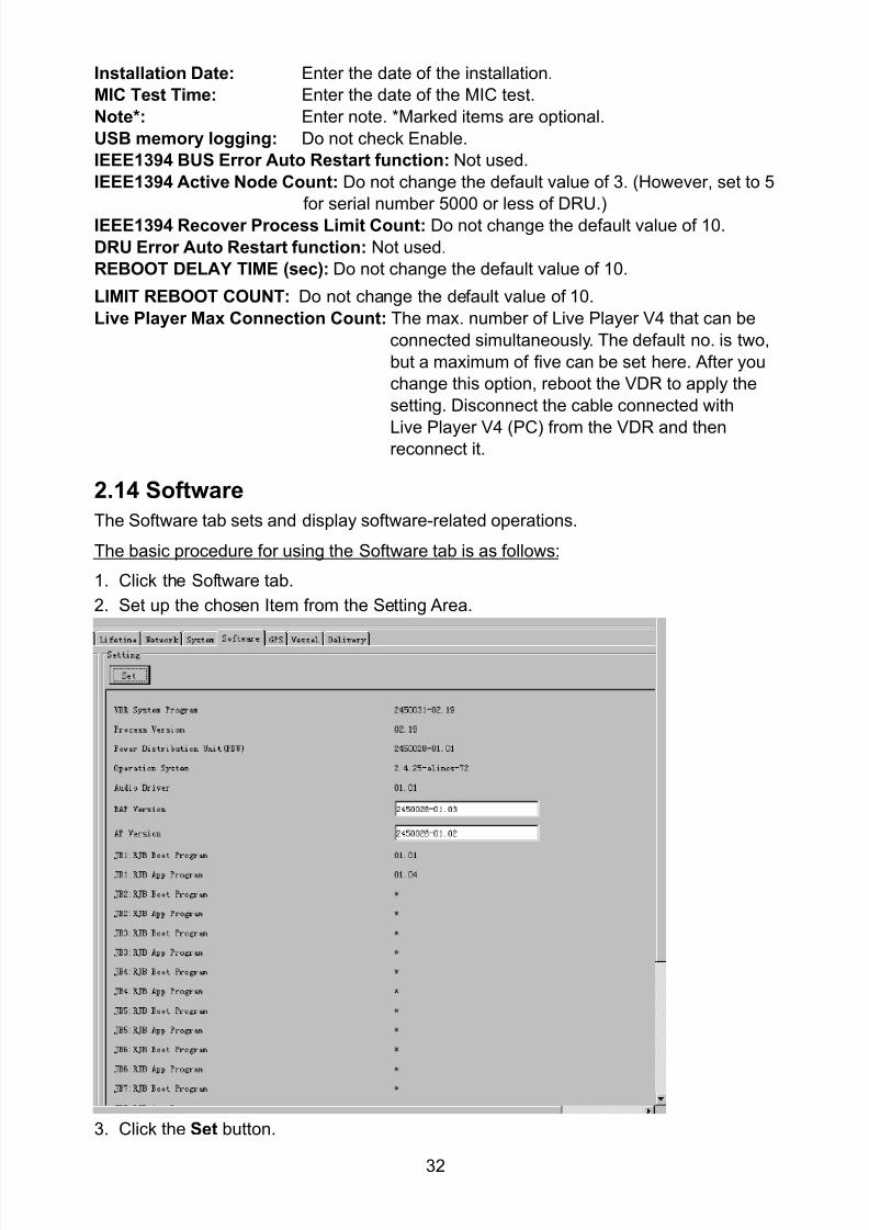
8102019 Ome44376d Vr3000 Mainte Cof26amp3bmol
httpslidepdfcomreaderfullome44376d-vr3000-mainte-cof26amp3bmol 3457
32
Installation Date Enter the date of the installation
MIC Test Time Enter the date of the MIC test
Note Enter note Marked items are optional
USB memory logging Do not check Enable
IEEE1394 BUS Error Auto Restart function Not used
IEEE1394 Active Node Count Do not change the default value of 3 (However set to 5
for serial number 5000 or less of DRU)
IEEE1394 Recover Process Limit Count Do not change the default value of 10
DRU Error Auto Restart function Not used
REBOOT DELAY TIME (sec) Do not change the default value of 10
LIMIT REBOOT COUNT Do not change the default value of 10
Live Player Max Connection Count The max number of Live Player V4 that can be
connected simultaneously The default no is two
but a maximum of five can be set here After you
change this option reboot the VDR to apply the
setting Disconnect the cable connected with
Live Player V4 (PC) from the VDR and thenreconnect it
214 Software
The Software tab sets and display software-related operations
The basic procedure for using the Software tab is as follows
1 Click the Software tab
2 Set up the chosen Item from the Setting Area
3 Click the Set button
8102019 Ome44376d Vr3000 Mainte Cof26amp3bmol
httpslidepdfcomreaderfullome44376d-vr3000-mainte-cof26amp3bmol 3557
33
The items in the Setting window work as follows
VDR System Program Display the VDR system program no
Process Version Display the process version
Power Distribution Unit (PDU) Display the version no of the PDU
Operation System Display the version no of the OS
Audio Driver Display the version no of the audio driverRAP Version Enter the version no of the RAP
AP Version Enter the version no of the AP
JB1-8 Boot Program Display the no of the RJB Boot program for Junction Boxes
1 to 8
JB1-8 App Program Display the no of the RJB App program for Junction Boxes
1 to 8
Watch Dog Interval Do not change the default value of 60 (Enter the process
response time A process is repeated if there is no response
within the time interval set here)
Giveup Interval Do not change the default value of 300 (Enter the restart
watch time The restarting of a process is stopped when the
number of times it has been restarted is exceeded within the
interval set here)
Refork Limit Do not change the default value of 10 (Enter the upper limit
for process restart The restarting of a process is stopped
when the number of times it has been restarted exceeds the
Give up Interval)
Note Enter note
Marked Items are optional
8102019 Ome44376d Vr3000 Mainte Cof26amp3bmol
httpslidepdfcomreaderfullome44376d-vr3000-mainte-cof26amp3bmol 3657
34
215 GPS
The GPS tab sets GPS-related parameters
The basic procedure for using the GPS tab is as follows
1 Click the GPS tab
2 Set up the chosen channel from the Information window3 Set up the chosen item in the Setting Area
4 Click the Set button
5 Repeat steps 2-4 to set up each Channel
6 Click the Check button to perform an inspection on all channels In the Information Area check column either OK or NG (No Good) is displayed
The items in the Setting window work as follows
Priority Display priority order
Date and Time SourceShip Position Source Set GPS source channel (serial channel
number for ZDA sentence)
Check Enable and disable checking
GPS Antenna Position From Bow Enter position of GPS antenna from bow
GPS Antenna Position From Stern Enter position of GPS antenna from stern
GPS Antenna Position From Port Enter position of GPS antenna from port
GPS Antenna Position From Starboard Enter position of GPS antenna from starboard
GPS Failure Threshold If the ZDA is input within the set time limit
the system restarts synchronized If not
input within the time limit the system restarts
without synchronization
8102019 Ome44376d Vr3000 Mainte Cof26amp3bmol
httpslidepdfcomreaderfullome44376d-vr3000-mainte-cof26amp3bmol 3757
35
GPS Delay Time by Time Sync Enter minimum time delay for time
synchronization Time synchronization is started
only in the time set here
GPS Difference Interval The time set here is added to the GPS time to
synchronize the system time Leave at the default
0 value setting
GPS Sync Giveup Time If the system receives the GPS time within the
time set the system synchronizes with the time
When not receiving a signal the system displays
an ldquoerror 26rdquo message
ZDA Timeout Enter value (seconds) for ZDA timeout (234 error)
from GPS
Note Enter and display note
Marked Items are optional
216 VesselThe Vessel tab sets and displays own ships information such as name and IMO number
The basic procedure for using the Vessel tab is as follows
1 Click the Vessel tab
2 Set up information in the Setting window
3 Click the Set button (Be sure to do this before moving to another port)
4 From the Maintenance menu click VDR Config Management and then Config5 Click the Write buttons to save data to the DRU backup HDD CF
The buttons in the Setting window works as follows
Vessel Name Enter name of vessel
Vessel IMO Number Enter IMO number of vessel
Vessel Flag Enter flag of vessel
Approval of Authority Enter name of approving authority
Note Enter note
Marked items are optional
8102019 Ome44376d Vr3000 Mainte Cof26amp3bmol
httpslidepdfcomreaderfullome44376d-vr3000-mainte-cof26amp3bmol 3857
36
217 Delivery
The Delivery tab functions to transmit data from the VDR to a PC via Ethernet LAN Do
not use this function during live connection
The basic procedure for using the Delivery tab is as follows
1 Click the Delivery tab
2 Click the Add button to show the Delivery Config window
3 Select protocol from the Protocol drop-down box (Unicast or Multicast)
4 Enter IP address in the IP address input box
5 Enter port number in the port number input box
6 Click the tab of the data to send (Analog Digital or Serial)
7 Select the channel of the data to send
8 If Serial was selected at step 6 select applicable data sentence from the Inactivewindow Click the right arrow to move the data sentence to the Active window
9 Click the OK button to close the Delivery Config window
10 The settings are listed in a table in the Delivery window Check the checkbox in the
Active column and then click the Set button
The buttons in the Setting window works as follows
Set Save edited settings
Add Create new delivery settings
Modify Modify selected delivery settings
Delete Delete selected delivery settings
8102019 Ome44376d Vr3000 Mainte Cof26amp3bmol
httpslidepdfcomreaderfullome44376d-vr3000-mainte-cof26amp3bmol 3957
37
3 How to Back up Configuration DataThis chapter shows how to back up configuration data to various storage media
Configuration data can be opened with Word Pad or any text editor other than Notepad
31 How to Back up Configuration Data to the Startup CompactFlash (CF)
Back up data to the startup CF after setting the VDR Configuration data is created on the
CF as a configini file
Note When the error shown below occurs during the downloading or uploading of
configuration data check the connection of the DRU Backup HDD and CF and then
upload or download the configuration data again
[CONN] Download failed
[CONN] Could not upload config file
If error occurs again re-install the VDR Maintenance Viewer
Do the following to back up data to a CF
1 Set up parameters on the tabs referring to Chapter 2
2 Click the Maintenance menu
3 Select VDR Config Management
4 Click the Upload button
5 A confirmation box appears click the OK button to start uploading to the VDR
6 Click the Write button where the arrow connects between VDR and DRU BackupHDD
7 A confirmation window appears click the OK button to save the configuration data tothe DRU and Backup HDD
8102019 Ome44376d Vr3000 Mainte Cof26amp3bmol
httpslidepdfcomreaderfullome44376d-vr3000-mainte-cof26amp3bmol 4057
38
8 Click the Write button where the arrow connects between the VDR and CF
9 A confirmation window appears click the OK button to save the configuration data tothe startup CF
10 Check that the PC VDR DRU Backup HDD and CF share the same VDR configcode
32 How to Back up Configuration Data to a PC
Configuration data saved to the PC can be edited with Wordpad and shared with other
vessels For future service ease it is recommended to backup configuration data to the
PC and have the data on board the vessel Also it is recommended to upload this data to
Furuno SMS (Service Management System) If unable to upload to Furuno SMS please
contact the Service Center Furuno Japan
To back up configuration data to the PC do as follows
1 Set up parameters on the tabs referring to Chapter 2
2 Click the Maintenance menu
3 Select VDR Config Management
4 Click the Export to button
5 A confirmation window appears click the OK button
6 Select where to save the data enter file name then click the Open button
7 Confirm that back up file is in the location selected
33 How to restore the default settings
Click the Default button on the VDR Config Management window to restore the default
settings of the DRU Backup HDD CF and VDR Maintenance Viewer
8102019 Ome44376d Vr3000 Mainte Cof26amp3bmol
httpslidepdfcomreaderfullome44376d-vr3000-mainte-cof26amp3bmol 4157
39
4 How to Upload Configuration Datafrom a PCThe procedure below shows how to upload configuration from the PC to aVR-3000VR-3000S
1 Click the Maintenance menu
2 Select VDR Config Management
3 Click the Import from button
4 The Open window appears Select configuration data and then click the Open button
5 Click the Upload button to upload data to the VR-3000VR-3000S
6 Click the Write buttons to save data to the DRU backup HDD and CF
8102019 Ome44376d Vr3000 Mainte Cof26amp3bmol
httpslidepdfcomreaderfullome44376d-vr3000-mainte-cof26amp3bmol 4257
40
5 Media ManagementThe media management feature deletes data from recording media initialization the
system etc There are two method LAN connection and Direct connection The Direct
connection takes longer time than the LAN connection Basically use the LAN connection
method
Note Initialization or creation of recording media is not available when Source Select onthe Live Player V4 is selected to Backup HDD
51 Initialization
This section shows how to delete data from the recording media Configuration data is
not deleted After performing the software configuration delete the data from the DRU
and HDD
Do the following to delete data from the DRU (LAN connection)
1 Set the PlaybackCPU switch in the DCU to the CPU position
2 Use an Ethernet cross cable to connect the PC to J14 (DATA) in the DCU (See page5)
3 Open the Tool menu
4 Select Media Management to open the VDR Media Management window
5 Check that IP address shown in the ldquoLAN Connect to IPrdquo in VDR Media Table Area isthe same as the IP address access point
6 Select ldquoLAN Connect to IPrdquo in the VDR Media Table column
8102019 Ome44376d Vr3000 Mainte Cof26amp3bmol
httpslidepdfcomreaderfullome44376d-vr3000-mainte-cof26amp3bmol 4357
41
7 Click the Analyze button A list of recording media connected to the VDR appears
Put a checkmark in the checkbox of the Select column for the DRU in the Name columnNote If there are several flash memories in the DRU all flash memories are shownCheck all flash memories shown
8 Select ldquoDRU Initializerdquo from the Operation dropdown list in the Operation area
10 Click the Run button
Do the following to delete data from the DRU (Direct connection)
1 Start Live Player V4 software
2 Open the Tool menu and select Source Select Select Live from the pull-downmenu
3 Click the Alarm tab and open Alarm History
4 Set the PlaybackCPU switch in the DCU to the Playback position
5 Wait approx 10 minutes and confirm that Alarm 174 occurs on Alarm History of LivePlayer V4
6 Connect an IEEEE1394 cable between J6 in the DCU and the PC
7 Open the Tool menu
8 Select Media Management to show the VDR Media Management window
9 Select Direct in the VDR Media Table column
10 Click the Analyze button A list of recording media connected to the VDR appears
11 Put a checkmark in the checkbox of the Select column for the DRU in the Namecolumn
Note If there are several flash memories in the DRU all flash memories are shownCheck all flash memories shown
12 Select ldquoDRU Initializerdquo from the Operation dropdown list in the Operation area
13 Enter password in the password column
14 Click the RUN button
8102019 Ome44376d Vr3000 Mainte Cof26amp3bmol
httpslidepdfcomreaderfullome44376d-vr3000-mainte-cof26amp3bmol 4457
42
Delete data from the Backup HDD as follows (LAN connection)
1 Set the PlaybackCPU switch in the DCU to the CPU position
2 Check that an Ethernet cross cable is connected between J14 in the DCU and the PC
3 Open the Tool menu
4 Select Media Management to open the VDR Media Management window
5 Check that IP address shown in the LAN Connect to IP in VDR Media Table Area is
the same as the IP address access point6 Select LAN Connect to IP in the VDR Media Table column
7 Click the Analyze button
8 A list of recording media connected to the VDR appears
9 Put a checkmark in the box of the Select column for the Backup HDD in the Namecolumn Select ldquoBackup HDD Initializerdquo from the Operation dropdown list in theOperation area
10 Click the Run button
Delete data from the Backup HDD as follows (Direct connection)
1 Start Live Player V4 software
2 Open the Tool menu and select Source Select Select Live from the pull-downmenu
3 Click the Alarm tab and open Alarm History
4 Set the PlaybackCPU switch in the DCU to the Playback position
5 Wait approx 10 minutes and confirm that Alarm 174 occurs on Alarm History of LivePlayer V4
6 Connect an IEEE1394 cable between J6 in the DCU and the PC
7 Open the Tool menu
8 Select Media Management to open the VDR Media Management window9 Select Direct in the VDR Media Table window
10 Click the Analyze button A list of recording media connected to the VDR appears
11 Put a checkmark in the check box of the Select column for the Backup HDD in theName column Select ldquoBackup HDD Initializerdquo from the Operation dropdown list in theOperation area
12 Enter password
13 Click the Run button
8102019 Ome44376d Vr3000 Mainte Cof26amp3bmol
httpslidepdfcomreaderfullome44376d-vr3000-mainte-cof26amp3bmol 4557
43
52 CreationThe Creation feature initializes recording media
Note1 This feature deletes ALL configuration data Backup all VDR configuration data
Note2 When you initialize medium that is a different format for the DRU or Backup HDDdelete all partitions with the disk management tool of Windows
Note3 When the Creation is failed try again If you can not initialize recording media tryunder condition as shown below
Do the Creation by the direct connection (When the Creation by the LAN
connection is failed)
Delete all partitions of the DRU or Backup HDD with the disk management tool of
Windows to do the Creation
If the Creation is still failed request service to repairreplace the DRU or Backup
HDD
Initialize the DRU as follows (LAN connection)
1 Set the PlaybackCPU switch in the DCU to the CPU position
2 Check that an Ethernet cross cable is connected between J14 in the DCU and the PC
3 Open the Tool menu
4 Select Media Management to open the VDR Media Management window
5 Check that IP address shown in the LAN Connect to IP in VDR Media Table Area isthe same as the IP address access point
6 Check ldquoLAN Connect to IPrdquo in the VDR Media Table column
7 Click the Analyze button A list of recording media connected to the VDR appears
8 Put a checkmark in the box of the Select column for the DRU in the Name column
Select ldquoDRU Creationrdquo from the Operation dropdown list in the Operation area
9 Click the Run button
Initialize the Backup HDD as follows (LAN connection)
1 To format the Backup HDD place a checkmark in the Select column of the listedrecord media in the Name column of the VDR Media Management dialogue box
2 From the Operation drop down list of the Operation area select ldquoBackup HDDCreation (Radar) or ldquoBackup HDD Creationrdquo
Two partition tools are available for the Backup HDD in the Media Management as
below
Backup HDD creation
This tool is used when the number of the SXGA video signal connected to the BackupHDD is the same as the DRU The same partition is created on both DRU and HDD
(1) When two SXGA video signals are recorded onto the HDD while 9-GB DRU isconnected
(2) When an SXGA video signal is recorded onto the HDD while 6-GB DRU isconnected
Backup HDD creation (radar)
This tool is used when two SXGA video signals are recorded onto the HDD with 6-GB
DRU connected The HDD has an area (radar) to record the second radar signal inaddition to the same partition as the DRU This tool cannot be used when 9-GB DRUis connected
3 Press the Run Button
8102019 Ome44376d Vr3000 Mainte Cof26amp3bmol
httpslidepdfcomreaderfullome44376d-vr3000-mainte-cof26amp3bmol 4657
44
Initialize the DRU as follows (Direct connection)
1 Start Live Player V4 software
2 Open the Tool menu and select Source Select Select Live from the pull-downmenu
3 Click the Alarm tab and open Alarm History
4 Set the PlaybackCPU switch in the DCU to the Playback position
5 Wait approx 10 minutes and confirm that Alarm 174 occurs on Alarm History of LivePlayer V4
6 Connect an IEEE1394 cable between J6 in the DCU and the PC
7 Open the Tool menu
8 Select Media Management to open the VDR Media Management window
9 Select Direct in the VDR Media Table window
10 Click the Analyze button A list of recording media connected to the VDR appears
11 Put a checkmark in the box of the Select column for the DRU and the desiredrecording media in the Name column In the Operation dropdown list of the Operationarea select ldquoDRU Creationrdquo
12 Enter password in the password column
13 Click the Run button
Initialize the Backup HDD as follows (Direct Connection)
1 To format the Backup HDD place a checkmark in the Select column of the listedrecord media in the Name column of the VDR Media Management dialogue box
2 From the Operation column of the Operation area select ldquoBackup HDD Creation(Radar) or ldquoBackup HDD Creationrdquo
Backup HDD creation
This tool is used when the number of the SXGA video signal connected to the BackupHDD is the same as the DRU The same partition is created on both DRU and HDD
(1) When two SXGA video signals are recorded onto the HDD while 9-GB DRU is
connected
(2) When an SXGA video signal is recorded onto the HDD while 6-GB DRU is
connected
Backup HDD creation (radar)
This tool is used when two SXGA video signals are recorded onto the HDD with 6-GBDRU connected The HDD has an area (radar) to record the second radar signal inaddition to the same partition as the DRU This tool cannot be used when 9-GB DRUis connected
3 Enter the password in the Password column
4 Press the Run Button
8102019 Ome44376d Vr3000 Mainte Cof26amp3bmol
httpslidepdfcomreaderfullome44376d-vr3000-mainte-cof26amp3bmol 4757
45
53 How to Enable Recording Area on the Backup HDD
This function enables writing over a recording area To prevent falsification of data all
recording areas must be saved otherwise this function is disabled To use this function push
the SAVE button Save the data before doing this procedure
Note Software version 135 or higher can enable writing over a recording area even if
all recording areas are not saved
Recording enable (LAN connection)
1 Set the PlaybackCPU switch in the DCU to the CPU position
2 Check that an Ethernet cross cable is connected between J14 in the DCU and the PC
3 Open the Tool menu
4 Select Media Management to open the VDR Media Management window
5 Check that IP address shown in the ldquoLAN Connect to IPrdquo in VDR Media Table Area isthe same as the IP address access point
6 Select ldquoLAN Connect to IPrdquo in the VDR Media Table column7 Click the Analyze button A list of recording media connected to the VDR appears
8 Put a checkmark in the box of the Select column for the Backup HDD in the Namecolumn
9 Select ldquoBackup HDD Recording Area Enablerdquo from the Operation dropdown list in theOperation area
10 Click the Run button
Recording enable (Direct connection)
1 Start Live Player V4 software
2 Open the Tool menu and select Source Select Select Live from the pull-down menu3 Click the Alarm tab and open Alarm History
4 Set the PlaybackCPU switch in the DCU to the Playback position
5 Wait approx 10 minutes and confirm that Alarm 174 occurs on Alarm History of LivePlayer V4
6 Connect an IEEE1394 cable between J6 in the DCU and the PC
7 Open the Tool menu
8 Select Media Management to open the VDR Media Management window
9 Select Direct in the VDR Media Table window
10 Click the Analyze button A list of recording media connected to the VDR appears11 Put a checkmark in the box of the Select column for the Backup HDD in the Name
column
12 Select ldquoBackup HDD Recording Area Enablerdquo from the Operation dropdown list in theOperation area
13 Enter password
14 Click the Run button
8102019 Ome44376d Vr3000 Mainte Cof26amp3bmol
httpslidepdfcomreaderfullome44376d-vr3000-mainte-cof26amp3bmol 4857
46
6 Other Functions
61 Software Management
The software download feature downloads VDR system software to the PC
To download software
1 Click the Maintenance menu
2 From the Software Management menu click Software Download to show theSoftware Download window
3 Enter the IP address 1000100 in the IP address box in the Update Server area
4 Click the Download Software button
5 The confirmation window appears click the OK button
The Software Backup Execute window shows the results of the download
Software is downloaded to C Program Files VDR Viewer Viewer Backup The software file
name is vdrtar
To Update Software
VDR system program version 16x can update the software with the procedure shownbelow
Note Do not update the file downloaded in procedures above
1 Click the Maintenance menu
2 From the Software Management menu click Software Upload to show the SoftwareUpload area
3 Click the Select button to show the Open window
4 Select update file (vdrtar) and click the Open button
8102019 Ome44376d Vr3000 Mainte Cof26amp3bmol
httpslidepdfcomreaderfullome44376d-vr3000-mainte-cof26amp3bmol 4957
47
5 Check the displayed Software information is correct
6 Enter the IP address 1000100 in the IP address box in the Update Server area
7 Enter password
8 Click the Update button
After the updating is completed the VDR is automatically restarted
Note Click the Restore button on the Software Update window to restore previoussoftware version This feature is available after updating the software
62 Password Management
The password can be changed for a serviceman to access the equipment Contact
FURUNO to get the default password to use during installation
Serviceman password
1 Click the Maintenance menu2 Select Change Serviceman Password from Password Management to show the
Change Serviceman Password window
3 Enter current password in the Old Password box
4 Enter the new password in the New Password box of the Change Password area
5 Enter new password again in the Confirm New Password box
6 Click the OK button
Audio password
The audio password set at the VDR Maintenance Viewer can be removed to enable
audio access without password1 Click the Maintenance menu
2 Select Change Audio Password from Password Management to show the Change Audio Password window
3 The confirmation window appears click the OK button
8102019 Ome44376d Vr3000 Mainte Cof26amp3bmol
httpslidepdfcomreaderfullome44376d-vr3000-mainte-cof26amp3bmol 5057
48
63 Record ComparisonThe integrity of the DRU and Backup HDD recordings can be compared This function isused by the RampD engineer for debugging
Follow the procedure as shown below
1 Click the Maintenance menu2 Select Record Comparison to show the Record Comparison window
The results are shown every 15 seconds in the Record Comparison window
8102019 Ome44376d Vr3000 Mainte Cof26amp3bmol
httpslidepdfcomreaderfullome44376d-vr3000-mainte-cof26amp3bmol 5157
49
64 Software History
This section shows you to save and configure software history (communications record)
How to save software history
Note When the error dialog appears while saving the software history restart the VDR
Maintenance Viewer
1 Click the Maintenance menu
2 Select Software History Collect
3 Click the Select button The Open dialog box appears
4 Select where to save the data then click the Open button
5 Select desired save condition then click the OK buttonNone No savingAt Once Save the software history manually Saving begins as soon as the OK button is clickedPeriodic For debugging Do not use otherwise The intervals are 30 sec 60 secand 120 secAlarm Detection For debugging Do not use otherwise Software history is savedwhen specified alarm is released Enter alarm number
How to configure software communications record
The RampD engineer uses this function for debugging Do not do this procedure unless
required Malfunction can result
1 Click the Maintenance menu
2 Select Software History Config
3 Do the followingProcess Select the type of communications record to save ALL saves allcommunications records
Detail Hide or show detailed information4 Click the Send button
8102019 Ome44376d Vr3000 Mainte Cof26amp3bmol
httpslidepdfcomreaderfullome44376d-vr3000-mainte-cof26amp3bmol 5257
50
65 Easy SetupThis feature sets equipment settings in batch and creates a data file of those settings
Default template The default template is created with the settings entered at installation
1 Click the Maintenance menu
2 Select Easy Setup to show the Template Selection window
3 Select Default Template
4 Click the Start button to show the Easy Setup window
5 Right click the channels (Radar Audio Digital Serial Analog) then select Edit toshow the Equipment Selection window
6 From the Equipment Directory window select equipment connected to the selectedchannel and then click the OK button
7 Repeat steps 5 and 6 to select equipment settings for each channel
8 Click the Save button in the Easy Setup window to show the Save window
9 Select where to save the file and enter file name
10 Click the Save button
8102019 Ome44376d Vr3000 Mainte Cof26amp3bmol
httpslidepdfcomreaderfullome44376d-vr3000-mainte-cof26amp3bmol 5357
51
Specific template Use a file already created
1 Click the Maintenance menu
2 Select Easy Setup to show the Template Selection window
3 Check Specified Template
4 Click the Select button and then select the file to edit
5 Click the Start button to show the Easy Setup window
6 Right click the channels (Radar Audio Digital Serial Analog) then select Edit toshow the Equipment Selection window
7 From the Equipment Directory window select equipment connected to the selectedchannel and then click the OK button
8 Repeat steps 6 and 7 to select equipment settings for each channel
9 Click the Save button in the Easy Setup window to show the Save window
10Select where to save the file and enter file name
11 Click the Save button
66 Equipment Management
This feature controls the import and export of equipment settings
Import data file
Import data files of equipment settings created in Easy Setup etc to the VDR
1 Click the Maintenance menu
2 Select Import from Equipment Management to show the Open window
3 Select the data file to import and click Open
Export data file
Export data files of equipment settings from the VDR to a PC
1 Click the Maintenance menu
2 Select Export from Equipment Management to show the Save window
3 Enter file name
4 Click the Save button
8102019 Ome44376d Vr3000 Mainte Cof26amp3bmol
httpslidepdfcomreaderfullome44376d-vr3000-mainte-cof26amp3bmol 5457
52
67 PC_RAP
This feature enables the same operation of the RAP (Remote Alarm Panel) from a PC
Select PC_RAP from the Tool menu to show the PC_RAP window
The buttons in the PC_RAP window function as shown below
SAVE Stop recording in the area where recording is currently being done
ACK Silence audio alarm
The PC_RAP display shows the following information with LEDs
RAP_LEDs Display the status of LEDs on the RAPSave The Save button blinks yellow when pushed When the 4 memory
areas have data recorded to them the Save button lights orange when
pushed
Normal Lights (green) where there are no unconfirmed or not restored
alarms
Error Flashes (red) for not confirmed alarm Lights (red) for unrestored
alarm
8102019 Ome44376d Vr3000 Mainte Cof26amp3bmol
httpslidepdfcomreaderfullome44376d-vr3000-mainte-cof26amp3bmol 5557
53
Backup HDD Information Display status of backup HDD
Selected Display current recording area and its status in green for
normal operation and in red for abnormal operation
Size Display capacity of backup HDD
Alarm area displays unconfirmed alarms
Time Display time alarm was generatedNumber Display number of alarm
Name Display name of alarm
Pending Alarm displays the unrestored alarms out of confirmed alarms only
Time Display time alarm was generated
Number Display number of alarm
Name Display name of alarm
8102019 Ome44376d Vr3000 Mainte Cof26amp3bmol
httpslidepdfcomreaderfullome44376d-vr3000-mainte-cof26amp3bmol 5657
54
68 Other
Status Monitor
The status monitor feature provides comprehensive data about the status of the VDR
From the menu bar click Toolgt Status Monitor to show the Status Monitor window
The buttons in the Status Monitor window work as shown below
Reload Settings for automatic refreshing of the status monitor
ON Turn automatic refresh OFF
OFF The Status Monitor is refreshed every five seconds
Save Available when Reload ON is selected The contents of the Status Monitor can be
saved to a text fileUpdate Update the Status Monitor display
Close Close the Status Monitor display
8102019 Ome44376d Vr3000 Mainte Cof26amp3bmol
httpslidepdfcomreaderfullome44376d-vr3000-mainte-cof26amp3bmol 5757
VDR Error List
This feature compiles all the errors shown on the RAP for easy reference
Access from MenugtToolgtVDR Error List
The VDR error list contains the following information
NO Display the number of the error
Title Display the name of the error
Detail Display details about the error
Exchange Check
This feature removes the alarms generated when replacing the DRU or backup HDD
Access MenugtToolgtExchange Check select either DRU or Backup HDD and click OK
Reboot
Reboot the VDR
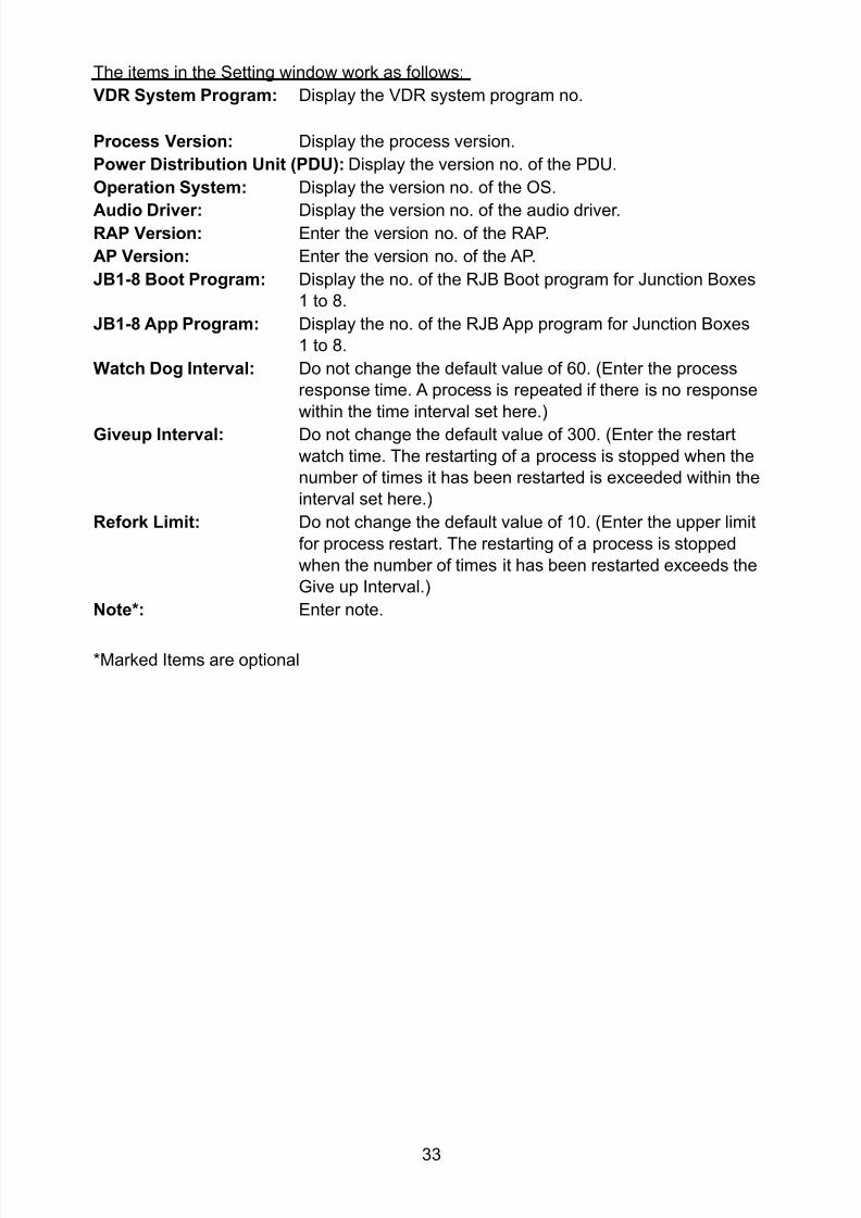
8102019 Ome44376d Vr3000 Mainte Cof26amp3bmol
httpslidepdfcomreaderfullome44376d-vr3000-mainte-cof26amp3bmol 3557
33
The items in the Setting window work as follows
VDR System Program Display the VDR system program no
Process Version Display the process version
Power Distribution Unit (PDU) Display the version no of the PDU
Operation System Display the version no of the OS
Audio Driver Display the version no of the audio driverRAP Version Enter the version no of the RAP
AP Version Enter the version no of the AP
JB1-8 Boot Program Display the no of the RJB Boot program for Junction Boxes
1 to 8
JB1-8 App Program Display the no of the RJB App program for Junction Boxes
1 to 8
Watch Dog Interval Do not change the default value of 60 (Enter the process
response time A process is repeated if there is no response
within the time interval set here)
Giveup Interval Do not change the default value of 300 (Enter the restart
watch time The restarting of a process is stopped when the
number of times it has been restarted is exceeded within the
interval set here)
Refork Limit Do not change the default value of 10 (Enter the upper limit
for process restart The restarting of a process is stopped
when the number of times it has been restarted exceeds the
Give up Interval)
Note Enter note
Marked Items are optional
8102019 Ome44376d Vr3000 Mainte Cof26amp3bmol
httpslidepdfcomreaderfullome44376d-vr3000-mainte-cof26amp3bmol 3657
34
215 GPS
The GPS tab sets GPS-related parameters
The basic procedure for using the GPS tab is as follows
1 Click the GPS tab
2 Set up the chosen channel from the Information window3 Set up the chosen item in the Setting Area
4 Click the Set button
5 Repeat steps 2-4 to set up each Channel
6 Click the Check button to perform an inspection on all channels In the Information Area check column either OK or NG (No Good) is displayed
The items in the Setting window work as follows
Priority Display priority order
Date and Time SourceShip Position Source Set GPS source channel (serial channel
number for ZDA sentence)
Check Enable and disable checking
GPS Antenna Position From Bow Enter position of GPS antenna from bow
GPS Antenna Position From Stern Enter position of GPS antenna from stern
GPS Antenna Position From Port Enter position of GPS antenna from port
GPS Antenna Position From Starboard Enter position of GPS antenna from starboard
GPS Failure Threshold If the ZDA is input within the set time limit
the system restarts synchronized If not
input within the time limit the system restarts
without synchronization
8102019 Ome44376d Vr3000 Mainte Cof26amp3bmol
httpslidepdfcomreaderfullome44376d-vr3000-mainte-cof26amp3bmol 3757
35
GPS Delay Time by Time Sync Enter minimum time delay for time
synchronization Time synchronization is started
only in the time set here
GPS Difference Interval The time set here is added to the GPS time to
synchronize the system time Leave at the default
0 value setting
GPS Sync Giveup Time If the system receives the GPS time within the
time set the system synchronizes with the time
When not receiving a signal the system displays
an ldquoerror 26rdquo message
ZDA Timeout Enter value (seconds) for ZDA timeout (234 error)
from GPS
Note Enter and display note
Marked Items are optional
216 VesselThe Vessel tab sets and displays own ships information such as name and IMO number
The basic procedure for using the Vessel tab is as follows
1 Click the Vessel tab
2 Set up information in the Setting window
3 Click the Set button (Be sure to do this before moving to another port)
4 From the Maintenance menu click VDR Config Management and then Config5 Click the Write buttons to save data to the DRU backup HDD CF
The buttons in the Setting window works as follows
Vessel Name Enter name of vessel
Vessel IMO Number Enter IMO number of vessel
Vessel Flag Enter flag of vessel
Approval of Authority Enter name of approving authority
Note Enter note
Marked items are optional
8102019 Ome44376d Vr3000 Mainte Cof26amp3bmol
httpslidepdfcomreaderfullome44376d-vr3000-mainte-cof26amp3bmol 3857
36
217 Delivery
The Delivery tab functions to transmit data from the VDR to a PC via Ethernet LAN Do
not use this function during live connection
The basic procedure for using the Delivery tab is as follows
1 Click the Delivery tab
2 Click the Add button to show the Delivery Config window
3 Select protocol from the Protocol drop-down box (Unicast or Multicast)
4 Enter IP address in the IP address input box
5 Enter port number in the port number input box
6 Click the tab of the data to send (Analog Digital or Serial)
7 Select the channel of the data to send
8 If Serial was selected at step 6 select applicable data sentence from the Inactivewindow Click the right arrow to move the data sentence to the Active window
9 Click the OK button to close the Delivery Config window
10 The settings are listed in a table in the Delivery window Check the checkbox in the
Active column and then click the Set button
The buttons in the Setting window works as follows
Set Save edited settings
Add Create new delivery settings
Modify Modify selected delivery settings
Delete Delete selected delivery settings
8102019 Ome44376d Vr3000 Mainte Cof26amp3bmol
httpslidepdfcomreaderfullome44376d-vr3000-mainte-cof26amp3bmol 3957
37
3 How to Back up Configuration DataThis chapter shows how to back up configuration data to various storage media
Configuration data can be opened with Word Pad or any text editor other than Notepad
31 How to Back up Configuration Data to the Startup CompactFlash (CF)
Back up data to the startup CF after setting the VDR Configuration data is created on the
CF as a configini file
Note When the error shown below occurs during the downloading or uploading of
configuration data check the connection of the DRU Backup HDD and CF and then
upload or download the configuration data again
[CONN] Download failed
[CONN] Could not upload config file
If error occurs again re-install the VDR Maintenance Viewer
Do the following to back up data to a CF
1 Set up parameters on the tabs referring to Chapter 2
2 Click the Maintenance menu
3 Select VDR Config Management
4 Click the Upload button
5 A confirmation box appears click the OK button to start uploading to the VDR
6 Click the Write button where the arrow connects between VDR and DRU BackupHDD
7 A confirmation window appears click the OK button to save the configuration data tothe DRU and Backup HDD
8102019 Ome44376d Vr3000 Mainte Cof26amp3bmol
httpslidepdfcomreaderfullome44376d-vr3000-mainte-cof26amp3bmol 4057
38
8 Click the Write button where the arrow connects between the VDR and CF
9 A confirmation window appears click the OK button to save the configuration data tothe startup CF
10 Check that the PC VDR DRU Backup HDD and CF share the same VDR configcode
32 How to Back up Configuration Data to a PC
Configuration data saved to the PC can be edited with Wordpad and shared with other
vessels For future service ease it is recommended to backup configuration data to the
PC and have the data on board the vessel Also it is recommended to upload this data to
Furuno SMS (Service Management System) If unable to upload to Furuno SMS please
contact the Service Center Furuno Japan
To back up configuration data to the PC do as follows
1 Set up parameters on the tabs referring to Chapter 2
2 Click the Maintenance menu
3 Select VDR Config Management
4 Click the Export to button
5 A confirmation window appears click the OK button
6 Select where to save the data enter file name then click the Open button
7 Confirm that back up file is in the location selected
33 How to restore the default settings
Click the Default button on the VDR Config Management window to restore the default
settings of the DRU Backup HDD CF and VDR Maintenance Viewer
8102019 Ome44376d Vr3000 Mainte Cof26amp3bmol
httpslidepdfcomreaderfullome44376d-vr3000-mainte-cof26amp3bmol 4157
39
4 How to Upload Configuration Datafrom a PCThe procedure below shows how to upload configuration from the PC to aVR-3000VR-3000S
1 Click the Maintenance menu
2 Select VDR Config Management
3 Click the Import from button
4 The Open window appears Select configuration data and then click the Open button
5 Click the Upload button to upload data to the VR-3000VR-3000S
6 Click the Write buttons to save data to the DRU backup HDD and CF
8102019 Ome44376d Vr3000 Mainte Cof26amp3bmol
httpslidepdfcomreaderfullome44376d-vr3000-mainte-cof26amp3bmol 4257
40
5 Media ManagementThe media management feature deletes data from recording media initialization the
system etc There are two method LAN connection and Direct connection The Direct
connection takes longer time than the LAN connection Basically use the LAN connection
method
Note Initialization or creation of recording media is not available when Source Select onthe Live Player V4 is selected to Backup HDD
51 Initialization
This section shows how to delete data from the recording media Configuration data is
not deleted After performing the software configuration delete the data from the DRU
and HDD
Do the following to delete data from the DRU (LAN connection)
1 Set the PlaybackCPU switch in the DCU to the CPU position
2 Use an Ethernet cross cable to connect the PC to J14 (DATA) in the DCU (See page5)
3 Open the Tool menu
4 Select Media Management to open the VDR Media Management window
5 Check that IP address shown in the ldquoLAN Connect to IPrdquo in VDR Media Table Area isthe same as the IP address access point
6 Select ldquoLAN Connect to IPrdquo in the VDR Media Table column
8102019 Ome44376d Vr3000 Mainte Cof26amp3bmol
httpslidepdfcomreaderfullome44376d-vr3000-mainte-cof26amp3bmol 4357
41
7 Click the Analyze button A list of recording media connected to the VDR appears
Put a checkmark in the checkbox of the Select column for the DRU in the Name columnNote If there are several flash memories in the DRU all flash memories are shownCheck all flash memories shown
8 Select ldquoDRU Initializerdquo from the Operation dropdown list in the Operation area
10 Click the Run button
Do the following to delete data from the DRU (Direct connection)
1 Start Live Player V4 software
2 Open the Tool menu and select Source Select Select Live from the pull-downmenu
3 Click the Alarm tab and open Alarm History
4 Set the PlaybackCPU switch in the DCU to the Playback position
5 Wait approx 10 minutes and confirm that Alarm 174 occurs on Alarm History of LivePlayer V4
6 Connect an IEEEE1394 cable between J6 in the DCU and the PC
7 Open the Tool menu
8 Select Media Management to show the VDR Media Management window
9 Select Direct in the VDR Media Table column
10 Click the Analyze button A list of recording media connected to the VDR appears
11 Put a checkmark in the checkbox of the Select column for the DRU in the Namecolumn
Note If there are several flash memories in the DRU all flash memories are shownCheck all flash memories shown
12 Select ldquoDRU Initializerdquo from the Operation dropdown list in the Operation area
13 Enter password in the password column
14 Click the RUN button
8102019 Ome44376d Vr3000 Mainte Cof26amp3bmol
httpslidepdfcomreaderfullome44376d-vr3000-mainte-cof26amp3bmol 4457
42
Delete data from the Backup HDD as follows (LAN connection)
1 Set the PlaybackCPU switch in the DCU to the CPU position
2 Check that an Ethernet cross cable is connected between J14 in the DCU and the PC
3 Open the Tool menu
4 Select Media Management to open the VDR Media Management window
5 Check that IP address shown in the LAN Connect to IP in VDR Media Table Area is
the same as the IP address access point6 Select LAN Connect to IP in the VDR Media Table column
7 Click the Analyze button
8 A list of recording media connected to the VDR appears
9 Put a checkmark in the box of the Select column for the Backup HDD in the Namecolumn Select ldquoBackup HDD Initializerdquo from the Operation dropdown list in theOperation area
10 Click the Run button
Delete data from the Backup HDD as follows (Direct connection)
1 Start Live Player V4 software
2 Open the Tool menu and select Source Select Select Live from the pull-downmenu
3 Click the Alarm tab and open Alarm History
4 Set the PlaybackCPU switch in the DCU to the Playback position
5 Wait approx 10 minutes and confirm that Alarm 174 occurs on Alarm History of LivePlayer V4
6 Connect an IEEE1394 cable between J6 in the DCU and the PC
7 Open the Tool menu
8 Select Media Management to open the VDR Media Management window9 Select Direct in the VDR Media Table window
10 Click the Analyze button A list of recording media connected to the VDR appears
11 Put a checkmark in the check box of the Select column for the Backup HDD in theName column Select ldquoBackup HDD Initializerdquo from the Operation dropdown list in theOperation area
12 Enter password
13 Click the Run button
8102019 Ome44376d Vr3000 Mainte Cof26amp3bmol
httpslidepdfcomreaderfullome44376d-vr3000-mainte-cof26amp3bmol 4557
43
52 CreationThe Creation feature initializes recording media
Note1 This feature deletes ALL configuration data Backup all VDR configuration data
Note2 When you initialize medium that is a different format for the DRU or Backup HDDdelete all partitions with the disk management tool of Windows
Note3 When the Creation is failed try again If you can not initialize recording media tryunder condition as shown below
Do the Creation by the direct connection (When the Creation by the LAN
connection is failed)
Delete all partitions of the DRU or Backup HDD with the disk management tool of
Windows to do the Creation
If the Creation is still failed request service to repairreplace the DRU or Backup
HDD
Initialize the DRU as follows (LAN connection)
1 Set the PlaybackCPU switch in the DCU to the CPU position
2 Check that an Ethernet cross cable is connected between J14 in the DCU and the PC
3 Open the Tool menu
4 Select Media Management to open the VDR Media Management window
5 Check that IP address shown in the LAN Connect to IP in VDR Media Table Area isthe same as the IP address access point
6 Check ldquoLAN Connect to IPrdquo in the VDR Media Table column
7 Click the Analyze button A list of recording media connected to the VDR appears
8 Put a checkmark in the box of the Select column for the DRU in the Name column
Select ldquoDRU Creationrdquo from the Operation dropdown list in the Operation area
9 Click the Run button
Initialize the Backup HDD as follows (LAN connection)
1 To format the Backup HDD place a checkmark in the Select column of the listedrecord media in the Name column of the VDR Media Management dialogue box
2 From the Operation drop down list of the Operation area select ldquoBackup HDDCreation (Radar) or ldquoBackup HDD Creationrdquo
Two partition tools are available for the Backup HDD in the Media Management as
below
Backup HDD creation
This tool is used when the number of the SXGA video signal connected to the BackupHDD is the same as the DRU The same partition is created on both DRU and HDD
(1) When two SXGA video signals are recorded onto the HDD while 9-GB DRU isconnected
(2) When an SXGA video signal is recorded onto the HDD while 6-GB DRU isconnected
Backup HDD creation (radar)
This tool is used when two SXGA video signals are recorded onto the HDD with 6-GB
DRU connected The HDD has an area (radar) to record the second radar signal inaddition to the same partition as the DRU This tool cannot be used when 9-GB DRUis connected
3 Press the Run Button
8102019 Ome44376d Vr3000 Mainte Cof26amp3bmol
httpslidepdfcomreaderfullome44376d-vr3000-mainte-cof26amp3bmol 4657
44
Initialize the DRU as follows (Direct connection)
1 Start Live Player V4 software
2 Open the Tool menu and select Source Select Select Live from the pull-downmenu
3 Click the Alarm tab and open Alarm History
4 Set the PlaybackCPU switch in the DCU to the Playback position
5 Wait approx 10 minutes and confirm that Alarm 174 occurs on Alarm History of LivePlayer V4
6 Connect an IEEE1394 cable between J6 in the DCU and the PC
7 Open the Tool menu
8 Select Media Management to open the VDR Media Management window
9 Select Direct in the VDR Media Table window
10 Click the Analyze button A list of recording media connected to the VDR appears
11 Put a checkmark in the box of the Select column for the DRU and the desiredrecording media in the Name column In the Operation dropdown list of the Operationarea select ldquoDRU Creationrdquo
12 Enter password in the password column
13 Click the Run button
Initialize the Backup HDD as follows (Direct Connection)
1 To format the Backup HDD place a checkmark in the Select column of the listedrecord media in the Name column of the VDR Media Management dialogue box
2 From the Operation column of the Operation area select ldquoBackup HDD Creation(Radar) or ldquoBackup HDD Creationrdquo
Backup HDD creation
This tool is used when the number of the SXGA video signal connected to the BackupHDD is the same as the DRU The same partition is created on both DRU and HDD
(1) When two SXGA video signals are recorded onto the HDD while 9-GB DRU is
connected
(2) When an SXGA video signal is recorded onto the HDD while 6-GB DRU is
connected
Backup HDD creation (radar)
This tool is used when two SXGA video signals are recorded onto the HDD with 6-GBDRU connected The HDD has an area (radar) to record the second radar signal inaddition to the same partition as the DRU This tool cannot be used when 9-GB DRUis connected
3 Enter the password in the Password column
4 Press the Run Button
8102019 Ome44376d Vr3000 Mainte Cof26amp3bmol
httpslidepdfcomreaderfullome44376d-vr3000-mainte-cof26amp3bmol 4757
45
53 How to Enable Recording Area on the Backup HDD
This function enables writing over a recording area To prevent falsification of data all
recording areas must be saved otherwise this function is disabled To use this function push
the SAVE button Save the data before doing this procedure
Note Software version 135 or higher can enable writing over a recording area even if
all recording areas are not saved
Recording enable (LAN connection)
1 Set the PlaybackCPU switch in the DCU to the CPU position
2 Check that an Ethernet cross cable is connected between J14 in the DCU and the PC
3 Open the Tool menu
4 Select Media Management to open the VDR Media Management window
5 Check that IP address shown in the ldquoLAN Connect to IPrdquo in VDR Media Table Area isthe same as the IP address access point
6 Select ldquoLAN Connect to IPrdquo in the VDR Media Table column7 Click the Analyze button A list of recording media connected to the VDR appears
8 Put a checkmark in the box of the Select column for the Backup HDD in the Namecolumn
9 Select ldquoBackup HDD Recording Area Enablerdquo from the Operation dropdown list in theOperation area
10 Click the Run button
Recording enable (Direct connection)
1 Start Live Player V4 software
2 Open the Tool menu and select Source Select Select Live from the pull-down menu3 Click the Alarm tab and open Alarm History
4 Set the PlaybackCPU switch in the DCU to the Playback position
5 Wait approx 10 minutes and confirm that Alarm 174 occurs on Alarm History of LivePlayer V4
6 Connect an IEEE1394 cable between J6 in the DCU and the PC
7 Open the Tool menu
8 Select Media Management to open the VDR Media Management window
9 Select Direct in the VDR Media Table window
10 Click the Analyze button A list of recording media connected to the VDR appears11 Put a checkmark in the box of the Select column for the Backup HDD in the Name
column
12 Select ldquoBackup HDD Recording Area Enablerdquo from the Operation dropdown list in theOperation area
13 Enter password
14 Click the Run button
8102019 Ome44376d Vr3000 Mainte Cof26amp3bmol
httpslidepdfcomreaderfullome44376d-vr3000-mainte-cof26amp3bmol 4857
46
6 Other Functions
61 Software Management
The software download feature downloads VDR system software to the PC
To download software
1 Click the Maintenance menu
2 From the Software Management menu click Software Download to show theSoftware Download window
3 Enter the IP address 1000100 in the IP address box in the Update Server area
4 Click the Download Software button
5 The confirmation window appears click the OK button
The Software Backup Execute window shows the results of the download
Software is downloaded to C Program Files VDR Viewer Viewer Backup The software file
name is vdrtar
To Update Software
VDR system program version 16x can update the software with the procedure shownbelow
Note Do not update the file downloaded in procedures above
1 Click the Maintenance menu
2 From the Software Management menu click Software Upload to show the SoftwareUpload area
3 Click the Select button to show the Open window
4 Select update file (vdrtar) and click the Open button
8102019 Ome44376d Vr3000 Mainte Cof26amp3bmol
httpslidepdfcomreaderfullome44376d-vr3000-mainte-cof26amp3bmol 4957
47
5 Check the displayed Software information is correct
6 Enter the IP address 1000100 in the IP address box in the Update Server area
7 Enter password
8 Click the Update button
After the updating is completed the VDR is automatically restarted
Note Click the Restore button on the Software Update window to restore previoussoftware version This feature is available after updating the software
62 Password Management
The password can be changed for a serviceman to access the equipment Contact
FURUNO to get the default password to use during installation
Serviceman password
1 Click the Maintenance menu2 Select Change Serviceman Password from Password Management to show the
Change Serviceman Password window
3 Enter current password in the Old Password box
4 Enter the new password in the New Password box of the Change Password area
5 Enter new password again in the Confirm New Password box
6 Click the OK button
Audio password
The audio password set at the VDR Maintenance Viewer can be removed to enable
audio access without password1 Click the Maintenance menu
2 Select Change Audio Password from Password Management to show the Change Audio Password window
3 The confirmation window appears click the OK button
8102019 Ome44376d Vr3000 Mainte Cof26amp3bmol
httpslidepdfcomreaderfullome44376d-vr3000-mainte-cof26amp3bmol 5057
48
63 Record ComparisonThe integrity of the DRU and Backup HDD recordings can be compared This function isused by the RampD engineer for debugging
Follow the procedure as shown below
1 Click the Maintenance menu2 Select Record Comparison to show the Record Comparison window
The results are shown every 15 seconds in the Record Comparison window
8102019 Ome44376d Vr3000 Mainte Cof26amp3bmol
httpslidepdfcomreaderfullome44376d-vr3000-mainte-cof26amp3bmol 5157
49
64 Software History
This section shows you to save and configure software history (communications record)
How to save software history
Note When the error dialog appears while saving the software history restart the VDR
Maintenance Viewer
1 Click the Maintenance menu
2 Select Software History Collect
3 Click the Select button The Open dialog box appears
4 Select where to save the data then click the Open button
5 Select desired save condition then click the OK buttonNone No savingAt Once Save the software history manually Saving begins as soon as the OK button is clickedPeriodic For debugging Do not use otherwise The intervals are 30 sec 60 secand 120 secAlarm Detection For debugging Do not use otherwise Software history is savedwhen specified alarm is released Enter alarm number
How to configure software communications record
The RampD engineer uses this function for debugging Do not do this procedure unless
required Malfunction can result
1 Click the Maintenance menu
2 Select Software History Config
3 Do the followingProcess Select the type of communications record to save ALL saves allcommunications records
Detail Hide or show detailed information4 Click the Send button
8102019 Ome44376d Vr3000 Mainte Cof26amp3bmol
httpslidepdfcomreaderfullome44376d-vr3000-mainte-cof26amp3bmol 5257
50
65 Easy SetupThis feature sets equipment settings in batch and creates a data file of those settings
Default template The default template is created with the settings entered at installation
1 Click the Maintenance menu
2 Select Easy Setup to show the Template Selection window
3 Select Default Template
4 Click the Start button to show the Easy Setup window
5 Right click the channels (Radar Audio Digital Serial Analog) then select Edit toshow the Equipment Selection window
6 From the Equipment Directory window select equipment connected to the selectedchannel and then click the OK button
7 Repeat steps 5 and 6 to select equipment settings for each channel
8 Click the Save button in the Easy Setup window to show the Save window
9 Select where to save the file and enter file name
10 Click the Save button
8102019 Ome44376d Vr3000 Mainte Cof26amp3bmol
httpslidepdfcomreaderfullome44376d-vr3000-mainte-cof26amp3bmol 5357
51
Specific template Use a file already created
1 Click the Maintenance menu
2 Select Easy Setup to show the Template Selection window
3 Check Specified Template
4 Click the Select button and then select the file to edit
5 Click the Start button to show the Easy Setup window
6 Right click the channels (Radar Audio Digital Serial Analog) then select Edit toshow the Equipment Selection window
7 From the Equipment Directory window select equipment connected to the selectedchannel and then click the OK button
8 Repeat steps 6 and 7 to select equipment settings for each channel
9 Click the Save button in the Easy Setup window to show the Save window
10Select where to save the file and enter file name
11 Click the Save button
66 Equipment Management
This feature controls the import and export of equipment settings
Import data file
Import data files of equipment settings created in Easy Setup etc to the VDR
1 Click the Maintenance menu
2 Select Import from Equipment Management to show the Open window
3 Select the data file to import and click Open
Export data file
Export data files of equipment settings from the VDR to a PC
1 Click the Maintenance menu
2 Select Export from Equipment Management to show the Save window
3 Enter file name
4 Click the Save button
8102019 Ome44376d Vr3000 Mainte Cof26amp3bmol
httpslidepdfcomreaderfullome44376d-vr3000-mainte-cof26amp3bmol 5457
52
67 PC_RAP
This feature enables the same operation of the RAP (Remote Alarm Panel) from a PC
Select PC_RAP from the Tool menu to show the PC_RAP window
The buttons in the PC_RAP window function as shown below
SAVE Stop recording in the area where recording is currently being done
ACK Silence audio alarm
The PC_RAP display shows the following information with LEDs
RAP_LEDs Display the status of LEDs on the RAPSave The Save button blinks yellow when pushed When the 4 memory
areas have data recorded to them the Save button lights orange when
pushed
Normal Lights (green) where there are no unconfirmed or not restored
alarms
Error Flashes (red) for not confirmed alarm Lights (red) for unrestored
alarm
8102019 Ome44376d Vr3000 Mainte Cof26amp3bmol
httpslidepdfcomreaderfullome44376d-vr3000-mainte-cof26amp3bmol 5557
53
Backup HDD Information Display status of backup HDD
Selected Display current recording area and its status in green for
normal operation and in red for abnormal operation
Size Display capacity of backup HDD
Alarm area displays unconfirmed alarms
Time Display time alarm was generatedNumber Display number of alarm
Name Display name of alarm
Pending Alarm displays the unrestored alarms out of confirmed alarms only
Time Display time alarm was generated
Number Display number of alarm
Name Display name of alarm
8102019 Ome44376d Vr3000 Mainte Cof26amp3bmol
httpslidepdfcomreaderfullome44376d-vr3000-mainte-cof26amp3bmol 5657
54
68 Other
Status Monitor
The status monitor feature provides comprehensive data about the status of the VDR
From the menu bar click Toolgt Status Monitor to show the Status Monitor window
The buttons in the Status Monitor window work as shown below
Reload Settings for automatic refreshing of the status monitor
ON Turn automatic refresh OFF
OFF The Status Monitor is refreshed every five seconds
Save Available when Reload ON is selected The contents of the Status Monitor can be
saved to a text fileUpdate Update the Status Monitor display
Close Close the Status Monitor display
8102019 Ome44376d Vr3000 Mainte Cof26amp3bmol
httpslidepdfcomreaderfullome44376d-vr3000-mainte-cof26amp3bmol 5757
VDR Error List
This feature compiles all the errors shown on the RAP for easy reference
Access from MenugtToolgtVDR Error List
The VDR error list contains the following information
NO Display the number of the error
Title Display the name of the error
Detail Display details about the error
Exchange Check
This feature removes the alarms generated when replacing the DRU or backup HDD
Access MenugtToolgtExchange Check select either DRU or Backup HDD and click OK
Reboot
Reboot the VDR
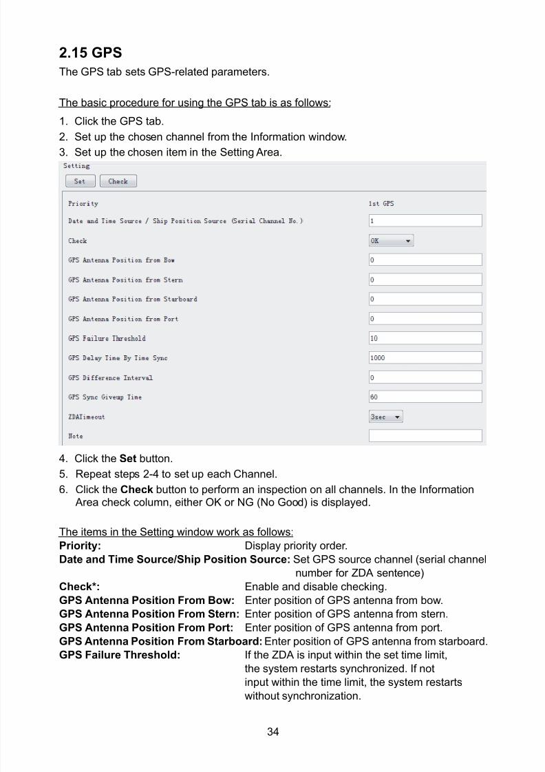
8102019 Ome44376d Vr3000 Mainte Cof26amp3bmol
httpslidepdfcomreaderfullome44376d-vr3000-mainte-cof26amp3bmol 3657
34
215 GPS
The GPS tab sets GPS-related parameters
The basic procedure for using the GPS tab is as follows
1 Click the GPS tab
2 Set up the chosen channel from the Information window3 Set up the chosen item in the Setting Area
4 Click the Set button
5 Repeat steps 2-4 to set up each Channel
6 Click the Check button to perform an inspection on all channels In the Information Area check column either OK or NG (No Good) is displayed
The items in the Setting window work as follows
Priority Display priority order
Date and Time SourceShip Position Source Set GPS source channel (serial channel
number for ZDA sentence)
Check Enable and disable checking
GPS Antenna Position From Bow Enter position of GPS antenna from bow
GPS Antenna Position From Stern Enter position of GPS antenna from stern
GPS Antenna Position From Port Enter position of GPS antenna from port
GPS Antenna Position From Starboard Enter position of GPS antenna from starboard
GPS Failure Threshold If the ZDA is input within the set time limit
the system restarts synchronized If not
input within the time limit the system restarts
without synchronization
8102019 Ome44376d Vr3000 Mainte Cof26amp3bmol
httpslidepdfcomreaderfullome44376d-vr3000-mainte-cof26amp3bmol 3757
35
GPS Delay Time by Time Sync Enter minimum time delay for time
synchronization Time synchronization is started
only in the time set here
GPS Difference Interval The time set here is added to the GPS time to
synchronize the system time Leave at the default
0 value setting
GPS Sync Giveup Time If the system receives the GPS time within the
time set the system synchronizes with the time
When not receiving a signal the system displays
an ldquoerror 26rdquo message
ZDA Timeout Enter value (seconds) for ZDA timeout (234 error)
from GPS
Note Enter and display note
Marked Items are optional
216 VesselThe Vessel tab sets and displays own ships information such as name and IMO number
The basic procedure for using the Vessel tab is as follows
1 Click the Vessel tab
2 Set up information in the Setting window
3 Click the Set button (Be sure to do this before moving to another port)
4 From the Maintenance menu click VDR Config Management and then Config5 Click the Write buttons to save data to the DRU backup HDD CF
The buttons in the Setting window works as follows
Vessel Name Enter name of vessel
Vessel IMO Number Enter IMO number of vessel
Vessel Flag Enter flag of vessel
Approval of Authority Enter name of approving authority
Note Enter note
Marked items are optional
8102019 Ome44376d Vr3000 Mainte Cof26amp3bmol
httpslidepdfcomreaderfullome44376d-vr3000-mainte-cof26amp3bmol 3857
36
217 Delivery
The Delivery tab functions to transmit data from the VDR to a PC via Ethernet LAN Do
not use this function during live connection
The basic procedure for using the Delivery tab is as follows
1 Click the Delivery tab
2 Click the Add button to show the Delivery Config window
3 Select protocol from the Protocol drop-down box (Unicast or Multicast)
4 Enter IP address in the IP address input box
5 Enter port number in the port number input box
6 Click the tab of the data to send (Analog Digital or Serial)
7 Select the channel of the data to send
8 If Serial was selected at step 6 select applicable data sentence from the Inactivewindow Click the right arrow to move the data sentence to the Active window
9 Click the OK button to close the Delivery Config window
10 The settings are listed in a table in the Delivery window Check the checkbox in the
Active column and then click the Set button
The buttons in the Setting window works as follows
Set Save edited settings
Add Create new delivery settings
Modify Modify selected delivery settings
Delete Delete selected delivery settings
8102019 Ome44376d Vr3000 Mainte Cof26amp3bmol
httpslidepdfcomreaderfullome44376d-vr3000-mainte-cof26amp3bmol 3957
37
3 How to Back up Configuration DataThis chapter shows how to back up configuration data to various storage media
Configuration data can be opened with Word Pad or any text editor other than Notepad
31 How to Back up Configuration Data to the Startup CompactFlash (CF)
Back up data to the startup CF after setting the VDR Configuration data is created on the
CF as a configini file
Note When the error shown below occurs during the downloading or uploading of
configuration data check the connection of the DRU Backup HDD and CF and then
upload or download the configuration data again
[CONN] Download failed
[CONN] Could not upload config file
If error occurs again re-install the VDR Maintenance Viewer
Do the following to back up data to a CF
1 Set up parameters on the tabs referring to Chapter 2
2 Click the Maintenance menu
3 Select VDR Config Management
4 Click the Upload button
5 A confirmation box appears click the OK button to start uploading to the VDR
6 Click the Write button where the arrow connects between VDR and DRU BackupHDD
7 A confirmation window appears click the OK button to save the configuration data tothe DRU and Backup HDD
8102019 Ome44376d Vr3000 Mainte Cof26amp3bmol
httpslidepdfcomreaderfullome44376d-vr3000-mainte-cof26amp3bmol 4057
38
8 Click the Write button where the arrow connects between the VDR and CF
9 A confirmation window appears click the OK button to save the configuration data tothe startup CF
10 Check that the PC VDR DRU Backup HDD and CF share the same VDR configcode
32 How to Back up Configuration Data to a PC
Configuration data saved to the PC can be edited with Wordpad and shared with other
vessels For future service ease it is recommended to backup configuration data to the
PC and have the data on board the vessel Also it is recommended to upload this data to
Furuno SMS (Service Management System) If unable to upload to Furuno SMS please
contact the Service Center Furuno Japan
To back up configuration data to the PC do as follows
1 Set up parameters on the tabs referring to Chapter 2
2 Click the Maintenance menu
3 Select VDR Config Management
4 Click the Export to button
5 A confirmation window appears click the OK button
6 Select where to save the data enter file name then click the Open button
7 Confirm that back up file is in the location selected
33 How to restore the default settings
Click the Default button on the VDR Config Management window to restore the default
settings of the DRU Backup HDD CF and VDR Maintenance Viewer
8102019 Ome44376d Vr3000 Mainte Cof26amp3bmol
httpslidepdfcomreaderfullome44376d-vr3000-mainte-cof26amp3bmol 4157
39
4 How to Upload Configuration Datafrom a PCThe procedure below shows how to upload configuration from the PC to aVR-3000VR-3000S
1 Click the Maintenance menu
2 Select VDR Config Management
3 Click the Import from button
4 The Open window appears Select configuration data and then click the Open button
5 Click the Upload button to upload data to the VR-3000VR-3000S
6 Click the Write buttons to save data to the DRU backup HDD and CF
8102019 Ome44376d Vr3000 Mainte Cof26amp3bmol
httpslidepdfcomreaderfullome44376d-vr3000-mainte-cof26amp3bmol 4257
40
5 Media ManagementThe media management feature deletes data from recording media initialization the
system etc There are two method LAN connection and Direct connection The Direct
connection takes longer time than the LAN connection Basically use the LAN connection
method
Note Initialization or creation of recording media is not available when Source Select onthe Live Player V4 is selected to Backup HDD
51 Initialization
This section shows how to delete data from the recording media Configuration data is
not deleted After performing the software configuration delete the data from the DRU
and HDD
Do the following to delete data from the DRU (LAN connection)
1 Set the PlaybackCPU switch in the DCU to the CPU position
2 Use an Ethernet cross cable to connect the PC to J14 (DATA) in the DCU (See page5)
3 Open the Tool menu
4 Select Media Management to open the VDR Media Management window
5 Check that IP address shown in the ldquoLAN Connect to IPrdquo in VDR Media Table Area isthe same as the IP address access point
6 Select ldquoLAN Connect to IPrdquo in the VDR Media Table column
8102019 Ome44376d Vr3000 Mainte Cof26amp3bmol
httpslidepdfcomreaderfullome44376d-vr3000-mainte-cof26amp3bmol 4357
41
7 Click the Analyze button A list of recording media connected to the VDR appears
Put a checkmark in the checkbox of the Select column for the DRU in the Name columnNote If there are several flash memories in the DRU all flash memories are shownCheck all flash memories shown
8 Select ldquoDRU Initializerdquo from the Operation dropdown list in the Operation area
10 Click the Run button
Do the following to delete data from the DRU (Direct connection)
1 Start Live Player V4 software
2 Open the Tool menu and select Source Select Select Live from the pull-downmenu
3 Click the Alarm tab and open Alarm History
4 Set the PlaybackCPU switch in the DCU to the Playback position
5 Wait approx 10 minutes and confirm that Alarm 174 occurs on Alarm History of LivePlayer V4
6 Connect an IEEEE1394 cable between J6 in the DCU and the PC
7 Open the Tool menu
8 Select Media Management to show the VDR Media Management window
9 Select Direct in the VDR Media Table column
10 Click the Analyze button A list of recording media connected to the VDR appears
11 Put a checkmark in the checkbox of the Select column for the DRU in the Namecolumn
Note If there are several flash memories in the DRU all flash memories are shownCheck all flash memories shown
12 Select ldquoDRU Initializerdquo from the Operation dropdown list in the Operation area
13 Enter password in the password column
14 Click the RUN button
8102019 Ome44376d Vr3000 Mainte Cof26amp3bmol
httpslidepdfcomreaderfullome44376d-vr3000-mainte-cof26amp3bmol 4457
42
Delete data from the Backup HDD as follows (LAN connection)
1 Set the PlaybackCPU switch in the DCU to the CPU position
2 Check that an Ethernet cross cable is connected between J14 in the DCU and the PC
3 Open the Tool menu
4 Select Media Management to open the VDR Media Management window
5 Check that IP address shown in the LAN Connect to IP in VDR Media Table Area is
the same as the IP address access point6 Select LAN Connect to IP in the VDR Media Table column
7 Click the Analyze button
8 A list of recording media connected to the VDR appears
9 Put a checkmark in the box of the Select column for the Backup HDD in the Namecolumn Select ldquoBackup HDD Initializerdquo from the Operation dropdown list in theOperation area
10 Click the Run button
Delete data from the Backup HDD as follows (Direct connection)
1 Start Live Player V4 software
2 Open the Tool menu and select Source Select Select Live from the pull-downmenu
3 Click the Alarm tab and open Alarm History
4 Set the PlaybackCPU switch in the DCU to the Playback position
5 Wait approx 10 minutes and confirm that Alarm 174 occurs on Alarm History of LivePlayer V4
6 Connect an IEEE1394 cable between J6 in the DCU and the PC
7 Open the Tool menu
8 Select Media Management to open the VDR Media Management window9 Select Direct in the VDR Media Table window
10 Click the Analyze button A list of recording media connected to the VDR appears
11 Put a checkmark in the check box of the Select column for the Backup HDD in theName column Select ldquoBackup HDD Initializerdquo from the Operation dropdown list in theOperation area
12 Enter password
13 Click the Run button
8102019 Ome44376d Vr3000 Mainte Cof26amp3bmol
httpslidepdfcomreaderfullome44376d-vr3000-mainte-cof26amp3bmol 4557
43
52 CreationThe Creation feature initializes recording media
Note1 This feature deletes ALL configuration data Backup all VDR configuration data
Note2 When you initialize medium that is a different format for the DRU or Backup HDDdelete all partitions with the disk management tool of Windows
Note3 When the Creation is failed try again If you can not initialize recording media tryunder condition as shown below
Do the Creation by the direct connection (When the Creation by the LAN
connection is failed)
Delete all partitions of the DRU or Backup HDD with the disk management tool of
Windows to do the Creation
If the Creation is still failed request service to repairreplace the DRU or Backup
HDD
Initialize the DRU as follows (LAN connection)
1 Set the PlaybackCPU switch in the DCU to the CPU position
2 Check that an Ethernet cross cable is connected between J14 in the DCU and the PC
3 Open the Tool menu
4 Select Media Management to open the VDR Media Management window
5 Check that IP address shown in the LAN Connect to IP in VDR Media Table Area isthe same as the IP address access point
6 Check ldquoLAN Connect to IPrdquo in the VDR Media Table column
7 Click the Analyze button A list of recording media connected to the VDR appears
8 Put a checkmark in the box of the Select column for the DRU in the Name column
Select ldquoDRU Creationrdquo from the Operation dropdown list in the Operation area
9 Click the Run button
Initialize the Backup HDD as follows (LAN connection)
1 To format the Backup HDD place a checkmark in the Select column of the listedrecord media in the Name column of the VDR Media Management dialogue box
2 From the Operation drop down list of the Operation area select ldquoBackup HDDCreation (Radar) or ldquoBackup HDD Creationrdquo
Two partition tools are available for the Backup HDD in the Media Management as
below
Backup HDD creation
This tool is used when the number of the SXGA video signal connected to the BackupHDD is the same as the DRU The same partition is created on both DRU and HDD
(1) When two SXGA video signals are recorded onto the HDD while 9-GB DRU isconnected
(2) When an SXGA video signal is recorded onto the HDD while 6-GB DRU isconnected
Backup HDD creation (radar)
This tool is used when two SXGA video signals are recorded onto the HDD with 6-GB
DRU connected The HDD has an area (radar) to record the second radar signal inaddition to the same partition as the DRU This tool cannot be used when 9-GB DRUis connected
3 Press the Run Button
8102019 Ome44376d Vr3000 Mainte Cof26amp3bmol
httpslidepdfcomreaderfullome44376d-vr3000-mainte-cof26amp3bmol 4657
44
Initialize the DRU as follows (Direct connection)
1 Start Live Player V4 software
2 Open the Tool menu and select Source Select Select Live from the pull-downmenu
3 Click the Alarm tab and open Alarm History
4 Set the PlaybackCPU switch in the DCU to the Playback position
5 Wait approx 10 minutes and confirm that Alarm 174 occurs on Alarm History of LivePlayer V4
6 Connect an IEEE1394 cable between J6 in the DCU and the PC
7 Open the Tool menu
8 Select Media Management to open the VDR Media Management window
9 Select Direct in the VDR Media Table window
10 Click the Analyze button A list of recording media connected to the VDR appears
11 Put a checkmark in the box of the Select column for the DRU and the desiredrecording media in the Name column In the Operation dropdown list of the Operationarea select ldquoDRU Creationrdquo
12 Enter password in the password column
13 Click the Run button
Initialize the Backup HDD as follows (Direct Connection)
1 To format the Backup HDD place a checkmark in the Select column of the listedrecord media in the Name column of the VDR Media Management dialogue box
2 From the Operation column of the Operation area select ldquoBackup HDD Creation(Radar) or ldquoBackup HDD Creationrdquo
Backup HDD creation
This tool is used when the number of the SXGA video signal connected to the BackupHDD is the same as the DRU The same partition is created on both DRU and HDD
(1) When two SXGA video signals are recorded onto the HDD while 9-GB DRU is
connected
(2) When an SXGA video signal is recorded onto the HDD while 6-GB DRU is
connected
Backup HDD creation (radar)
This tool is used when two SXGA video signals are recorded onto the HDD with 6-GBDRU connected The HDD has an area (radar) to record the second radar signal inaddition to the same partition as the DRU This tool cannot be used when 9-GB DRUis connected
3 Enter the password in the Password column
4 Press the Run Button
8102019 Ome44376d Vr3000 Mainte Cof26amp3bmol
httpslidepdfcomreaderfullome44376d-vr3000-mainte-cof26amp3bmol 4757
45
53 How to Enable Recording Area on the Backup HDD
This function enables writing over a recording area To prevent falsification of data all
recording areas must be saved otherwise this function is disabled To use this function push
the SAVE button Save the data before doing this procedure
Note Software version 135 or higher can enable writing over a recording area even if
all recording areas are not saved
Recording enable (LAN connection)
1 Set the PlaybackCPU switch in the DCU to the CPU position
2 Check that an Ethernet cross cable is connected between J14 in the DCU and the PC
3 Open the Tool menu
4 Select Media Management to open the VDR Media Management window
5 Check that IP address shown in the ldquoLAN Connect to IPrdquo in VDR Media Table Area isthe same as the IP address access point
6 Select ldquoLAN Connect to IPrdquo in the VDR Media Table column7 Click the Analyze button A list of recording media connected to the VDR appears
8 Put a checkmark in the box of the Select column for the Backup HDD in the Namecolumn
9 Select ldquoBackup HDD Recording Area Enablerdquo from the Operation dropdown list in theOperation area
10 Click the Run button
Recording enable (Direct connection)
1 Start Live Player V4 software
2 Open the Tool menu and select Source Select Select Live from the pull-down menu3 Click the Alarm tab and open Alarm History
4 Set the PlaybackCPU switch in the DCU to the Playback position
5 Wait approx 10 minutes and confirm that Alarm 174 occurs on Alarm History of LivePlayer V4
6 Connect an IEEE1394 cable between J6 in the DCU and the PC
7 Open the Tool menu
8 Select Media Management to open the VDR Media Management window
9 Select Direct in the VDR Media Table window
10 Click the Analyze button A list of recording media connected to the VDR appears11 Put a checkmark in the box of the Select column for the Backup HDD in the Name
column
12 Select ldquoBackup HDD Recording Area Enablerdquo from the Operation dropdown list in theOperation area
13 Enter password
14 Click the Run button
8102019 Ome44376d Vr3000 Mainte Cof26amp3bmol
httpslidepdfcomreaderfullome44376d-vr3000-mainte-cof26amp3bmol 4857
46
6 Other Functions
61 Software Management
The software download feature downloads VDR system software to the PC
To download software
1 Click the Maintenance menu
2 From the Software Management menu click Software Download to show theSoftware Download window
3 Enter the IP address 1000100 in the IP address box in the Update Server area
4 Click the Download Software button
5 The confirmation window appears click the OK button
The Software Backup Execute window shows the results of the download
Software is downloaded to C Program Files VDR Viewer Viewer Backup The software file
name is vdrtar
To Update Software
VDR system program version 16x can update the software with the procedure shownbelow
Note Do not update the file downloaded in procedures above
1 Click the Maintenance menu
2 From the Software Management menu click Software Upload to show the SoftwareUpload area
3 Click the Select button to show the Open window
4 Select update file (vdrtar) and click the Open button
8102019 Ome44376d Vr3000 Mainte Cof26amp3bmol
httpslidepdfcomreaderfullome44376d-vr3000-mainte-cof26amp3bmol 4957
47
5 Check the displayed Software information is correct
6 Enter the IP address 1000100 in the IP address box in the Update Server area
7 Enter password
8 Click the Update button
After the updating is completed the VDR is automatically restarted
Note Click the Restore button on the Software Update window to restore previoussoftware version This feature is available after updating the software
62 Password Management
The password can be changed for a serviceman to access the equipment Contact
FURUNO to get the default password to use during installation
Serviceman password
1 Click the Maintenance menu2 Select Change Serviceman Password from Password Management to show the
Change Serviceman Password window
3 Enter current password in the Old Password box
4 Enter the new password in the New Password box of the Change Password area
5 Enter new password again in the Confirm New Password box
6 Click the OK button
Audio password
The audio password set at the VDR Maintenance Viewer can be removed to enable
audio access without password1 Click the Maintenance menu
2 Select Change Audio Password from Password Management to show the Change Audio Password window
3 The confirmation window appears click the OK button
8102019 Ome44376d Vr3000 Mainte Cof26amp3bmol
httpslidepdfcomreaderfullome44376d-vr3000-mainte-cof26amp3bmol 5057
48
63 Record ComparisonThe integrity of the DRU and Backup HDD recordings can be compared This function isused by the RampD engineer for debugging
Follow the procedure as shown below
1 Click the Maintenance menu2 Select Record Comparison to show the Record Comparison window
The results are shown every 15 seconds in the Record Comparison window
8102019 Ome44376d Vr3000 Mainte Cof26amp3bmol
httpslidepdfcomreaderfullome44376d-vr3000-mainte-cof26amp3bmol 5157
49
64 Software History
This section shows you to save and configure software history (communications record)
How to save software history
Note When the error dialog appears while saving the software history restart the VDR
Maintenance Viewer
1 Click the Maintenance menu
2 Select Software History Collect
3 Click the Select button The Open dialog box appears
4 Select where to save the data then click the Open button
5 Select desired save condition then click the OK buttonNone No savingAt Once Save the software history manually Saving begins as soon as the OK button is clickedPeriodic For debugging Do not use otherwise The intervals are 30 sec 60 secand 120 secAlarm Detection For debugging Do not use otherwise Software history is savedwhen specified alarm is released Enter alarm number
How to configure software communications record
The RampD engineer uses this function for debugging Do not do this procedure unless
required Malfunction can result
1 Click the Maintenance menu
2 Select Software History Config
3 Do the followingProcess Select the type of communications record to save ALL saves allcommunications records
Detail Hide or show detailed information4 Click the Send button
8102019 Ome44376d Vr3000 Mainte Cof26amp3bmol
httpslidepdfcomreaderfullome44376d-vr3000-mainte-cof26amp3bmol 5257
50
65 Easy SetupThis feature sets equipment settings in batch and creates a data file of those settings
Default template The default template is created with the settings entered at installation
1 Click the Maintenance menu
2 Select Easy Setup to show the Template Selection window
3 Select Default Template
4 Click the Start button to show the Easy Setup window
5 Right click the channels (Radar Audio Digital Serial Analog) then select Edit toshow the Equipment Selection window
6 From the Equipment Directory window select equipment connected to the selectedchannel and then click the OK button
7 Repeat steps 5 and 6 to select equipment settings for each channel
8 Click the Save button in the Easy Setup window to show the Save window
9 Select where to save the file and enter file name
10 Click the Save button
8102019 Ome44376d Vr3000 Mainte Cof26amp3bmol
httpslidepdfcomreaderfullome44376d-vr3000-mainte-cof26amp3bmol 5357
51
Specific template Use a file already created
1 Click the Maintenance menu
2 Select Easy Setup to show the Template Selection window
3 Check Specified Template
4 Click the Select button and then select the file to edit
5 Click the Start button to show the Easy Setup window
6 Right click the channels (Radar Audio Digital Serial Analog) then select Edit toshow the Equipment Selection window
7 From the Equipment Directory window select equipment connected to the selectedchannel and then click the OK button
8 Repeat steps 6 and 7 to select equipment settings for each channel
9 Click the Save button in the Easy Setup window to show the Save window
10Select where to save the file and enter file name
11 Click the Save button
66 Equipment Management
This feature controls the import and export of equipment settings
Import data file
Import data files of equipment settings created in Easy Setup etc to the VDR
1 Click the Maintenance menu
2 Select Import from Equipment Management to show the Open window
3 Select the data file to import and click Open
Export data file
Export data files of equipment settings from the VDR to a PC
1 Click the Maintenance menu
2 Select Export from Equipment Management to show the Save window
3 Enter file name
4 Click the Save button
8102019 Ome44376d Vr3000 Mainte Cof26amp3bmol
httpslidepdfcomreaderfullome44376d-vr3000-mainte-cof26amp3bmol 5457
52
67 PC_RAP
This feature enables the same operation of the RAP (Remote Alarm Panel) from a PC
Select PC_RAP from the Tool menu to show the PC_RAP window
The buttons in the PC_RAP window function as shown below
SAVE Stop recording in the area where recording is currently being done
ACK Silence audio alarm
The PC_RAP display shows the following information with LEDs
RAP_LEDs Display the status of LEDs on the RAPSave The Save button blinks yellow when pushed When the 4 memory
areas have data recorded to them the Save button lights orange when
pushed
Normal Lights (green) where there are no unconfirmed or not restored
alarms
Error Flashes (red) for not confirmed alarm Lights (red) for unrestored
alarm
8102019 Ome44376d Vr3000 Mainte Cof26amp3bmol
httpslidepdfcomreaderfullome44376d-vr3000-mainte-cof26amp3bmol 5557
53
Backup HDD Information Display status of backup HDD
Selected Display current recording area and its status in green for
normal operation and in red for abnormal operation
Size Display capacity of backup HDD
Alarm area displays unconfirmed alarms
Time Display time alarm was generatedNumber Display number of alarm
Name Display name of alarm
Pending Alarm displays the unrestored alarms out of confirmed alarms only
Time Display time alarm was generated
Number Display number of alarm
Name Display name of alarm
8102019 Ome44376d Vr3000 Mainte Cof26amp3bmol
httpslidepdfcomreaderfullome44376d-vr3000-mainte-cof26amp3bmol 5657
54
68 Other
Status Monitor
The status monitor feature provides comprehensive data about the status of the VDR
From the menu bar click Toolgt Status Monitor to show the Status Monitor window
The buttons in the Status Monitor window work as shown below
Reload Settings for automatic refreshing of the status monitor
ON Turn automatic refresh OFF
OFF The Status Monitor is refreshed every five seconds
Save Available when Reload ON is selected The contents of the Status Monitor can be
saved to a text fileUpdate Update the Status Monitor display
Close Close the Status Monitor display
8102019 Ome44376d Vr3000 Mainte Cof26amp3bmol
httpslidepdfcomreaderfullome44376d-vr3000-mainte-cof26amp3bmol 5757
VDR Error List
This feature compiles all the errors shown on the RAP for easy reference
Access from MenugtToolgtVDR Error List
The VDR error list contains the following information
NO Display the number of the error
Title Display the name of the error
Detail Display details about the error
Exchange Check
This feature removes the alarms generated when replacing the DRU or backup HDD
Access MenugtToolgtExchange Check select either DRU or Backup HDD and click OK
Reboot
Reboot the VDR
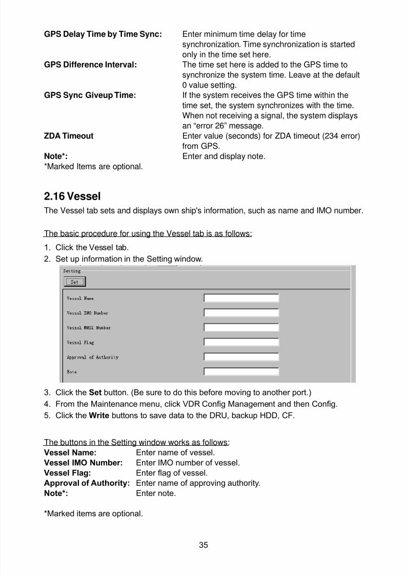
8102019 Ome44376d Vr3000 Mainte Cof26amp3bmol
httpslidepdfcomreaderfullome44376d-vr3000-mainte-cof26amp3bmol 3757
35
GPS Delay Time by Time Sync Enter minimum time delay for time
synchronization Time synchronization is started
only in the time set here
GPS Difference Interval The time set here is added to the GPS time to
synchronize the system time Leave at the default
0 value setting
GPS Sync Giveup Time If the system receives the GPS time within the
time set the system synchronizes with the time
When not receiving a signal the system displays
an ldquoerror 26rdquo message
ZDA Timeout Enter value (seconds) for ZDA timeout (234 error)
from GPS
Note Enter and display note
Marked Items are optional
216 VesselThe Vessel tab sets and displays own ships information such as name and IMO number
The basic procedure for using the Vessel tab is as follows
1 Click the Vessel tab
2 Set up information in the Setting window
3 Click the Set button (Be sure to do this before moving to another port)
4 From the Maintenance menu click VDR Config Management and then Config5 Click the Write buttons to save data to the DRU backup HDD CF
The buttons in the Setting window works as follows
Vessel Name Enter name of vessel
Vessel IMO Number Enter IMO number of vessel
Vessel Flag Enter flag of vessel
Approval of Authority Enter name of approving authority
Note Enter note
Marked items are optional
8102019 Ome44376d Vr3000 Mainte Cof26amp3bmol
httpslidepdfcomreaderfullome44376d-vr3000-mainte-cof26amp3bmol 3857
36
217 Delivery
The Delivery tab functions to transmit data from the VDR to a PC via Ethernet LAN Do
not use this function during live connection
The basic procedure for using the Delivery tab is as follows
1 Click the Delivery tab
2 Click the Add button to show the Delivery Config window
3 Select protocol from the Protocol drop-down box (Unicast or Multicast)
4 Enter IP address in the IP address input box
5 Enter port number in the port number input box
6 Click the tab of the data to send (Analog Digital or Serial)
7 Select the channel of the data to send
8 If Serial was selected at step 6 select applicable data sentence from the Inactivewindow Click the right arrow to move the data sentence to the Active window
9 Click the OK button to close the Delivery Config window
10 The settings are listed in a table in the Delivery window Check the checkbox in the
Active column and then click the Set button
The buttons in the Setting window works as follows
Set Save edited settings
Add Create new delivery settings
Modify Modify selected delivery settings
Delete Delete selected delivery settings
8102019 Ome44376d Vr3000 Mainte Cof26amp3bmol
httpslidepdfcomreaderfullome44376d-vr3000-mainte-cof26amp3bmol 3957
37
3 How to Back up Configuration DataThis chapter shows how to back up configuration data to various storage media
Configuration data can be opened with Word Pad or any text editor other than Notepad
31 How to Back up Configuration Data to the Startup CompactFlash (CF)
Back up data to the startup CF after setting the VDR Configuration data is created on the
CF as a configini file
Note When the error shown below occurs during the downloading or uploading of
configuration data check the connection of the DRU Backup HDD and CF and then
upload or download the configuration data again
[CONN] Download failed
[CONN] Could not upload config file
If error occurs again re-install the VDR Maintenance Viewer
Do the following to back up data to a CF
1 Set up parameters on the tabs referring to Chapter 2
2 Click the Maintenance menu
3 Select VDR Config Management
4 Click the Upload button
5 A confirmation box appears click the OK button to start uploading to the VDR
6 Click the Write button where the arrow connects between VDR and DRU BackupHDD
7 A confirmation window appears click the OK button to save the configuration data tothe DRU and Backup HDD
8102019 Ome44376d Vr3000 Mainte Cof26amp3bmol
httpslidepdfcomreaderfullome44376d-vr3000-mainte-cof26amp3bmol 4057
38
8 Click the Write button where the arrow connects between the VDR and CF
9 A confirmation window appears click the OK button to save the configuration data tothe startup CF
10 Check that the PC VDR DRU Backup HDD and CF share the same VDR configcode
32 How to Back up Configuration Data to a PC
Configuration data saved to the PC can be edited with Wordpad and shared with other
vessels For future service ease it is recommended to backup configuration data to the
PC and have the data on board the vessel Also it is recommended to upload this data to
Furuno SMS (Service Management System) If unable to upload to Furuno SMS please
contact the Service Center Furuno Japan
To back up configuration data to the PC do as follows
1 Set up parameters on the tabs referring to Chapter 2
2 Click the Maintenance menu
3 Select VDR Config Management
4 Click the Export to button
5 A confirmation window appears click the OK button
6 Select where to save the data enter file name then click the Open button
7 Confirm that back up file is in the location selected
33 How to restore the default settings
Click the Default button on the VDR Config Management window to restore the default
settings of the DRU Backup HDD CF and VDR Maintenance Viewer
8102019 Ome44376d Vr3000 Mainte Cof26amp3bmol
httpslidepdfcomreaderfullome44376d-vr3000-mainte-cof26amp3bmol 4157
39
4 How to Upload Configuration Datafrom a PCThe procedure below shows how to upload configuration from the PC to aVR-3000VR-3000S
1 Click the Maintenance menu
2 Select VDR Config Management
3 Click the Import from button
4 The Open window appears Select configuration data and then click the Open button
5 Click the Upload button to upload data to the VR-3000VR-3000S
6 Click the Write buttons to save data to the DRU backup HDD and CF
8102019 Ome44376d Vr3000 Mainte Cof26amp3bmol
httpslidepdfcomreaderfullome44376d-vr3000-mainte-cof26amp3bmol 4257
40
5 Media ManagementThe media management feature deletes data from recording media initialization the
system etc There are two method LAN connection and Direct connection The Direct
connection takes longer time than the LAN connection Basically use the LAN connection
method
Note Initialization or creation of recording media is not available when Source Select onthe Live Player V4 is selected to Backup HDD
51 Initialization
This section shows how to delete data from the recording media Configuration data is
not deleted After performing the software configuration delete the data from the DRU
and HDD
Do the following to delete data from the DRU (LAN connection)
1 Set the PlaybackCPU switch in the DCU to the CPU position
2 Use an Ethernet cross cable to connect the PC to J14 (DATA) in the DCU (See page5)
3 Open the Tool menu
4 Select Media Management to open the VDR Media Management window
5 Check that IP address shown in the ldquoLAN Connect to IPrdquo in VDR Media Table Area isthe same as the IP address access point
6 Select ldquoLAN Connect to IPrdquo in the VDR Media Table column
8102019 Ome44376d Vr3000 Mainte Cof26amp3bmol
httpslidepdfcomreaderfullome44376d-vr3000-mainte-cof26amp3bmol 4357
41
7 Click the Analyze button A list of recording media connected to the VDR appears
Put a checkmark in the checkbox of the Select column for the DRU in the Name columnNote If there are several flash memories in the DRU all flash memories are shownCheck all flash memories shown
8 Select ldquoDRU Initializerdquo from the Operation dropdown list in the Operation area
10 Click the Run button
Do the following to delete data from the DRU (Direct connection)
1 Start Live Player V4 software
2 Open the Tool menu and select Source Select Select Live from the pull-downmenu
3 Click the Alarm tab and open Alarm History
4 Set the PlaybackCPU switch in the DCU to the Playback position
5 Wait approx 10 minutes and confirm that Alarm 174 occurs on Alarm History of LivePlayer V4
6 Connect an IEEEE1394 cable between J6 in the DCU and the PC
7 Open the Tool menu
8 Select Media Management to show the VDR Media Management window
9 Select Direct in the VDR Media Table column
10 Click the Analyze button A list of recording media connected to the VDR appears
11 Put a checkmark in the checkbox of the Select column for the DRU in the Namecolumn
Note If there are several flash memories in the DRU all flash memories are shownCheck all flash memories shown
12 Select ldquoDRU Initializerdquo from the Operation dropdown list in the Operation area
13 Enter password in the password column
14 Click the RUN button
8102019 Ome44376d Vr3000 Mainte Cof26amp3bmol
httpslidepdfcomreaderfullome44376d-vr3000-mainte-cof26amp3bmol 4457
42
Delete data from the Backup HDD as follows (LAN connection)
1 Set the PlaybackCPU switch in the DCU to the CPU position
2 Check that an Ethernet cross cable is connected between J14 in the DCU and the PC
3 Open the Tool menu
4 Select Media Management to open the VDR Media Management window
5 Check that IP address shown in the LAN Connect to IP in VDR Media Table Area is
the same as the IP address access point6 Select LAN Connect to IP in the VDR Media Table column
7 Click the Analyze button
8 A list of recording media connected to the VDR appears
9 Put a checkmark in the box of the Select column for the Backup HDD in the Namecolumn Select ldquoBackup HDD Initializerdquo from the Operation dropdown list in theOperation area
10 Click the Run button
Delete data from the Backup HDD as follows (Direct connection)
1 Start Live Player V4 software
2 Open the Tool menu and select Source Select Select Live from the pull-downmenu
3 Click the Alarm tab and open Alarm History
4 Set the PlaybackCPU switch in the DCU to the Playback position
5 Wait approx 10 minutes and confirm that Alarm 174 occurs on Alarm History of LivePlayer V4
6 Connect an IEEE1394 cable between J6 in the DCU and the PC
7 Open the Tool menu
8 Select Media Management to open the VDR Media Management window9 Select Direct in the VDR Media Table window
10 Click the Analyze button A list of recording media connected to the VDR appears
11 Put a checkmark in the check box of the Select column for the Backup HDD in theName column Select ldquoBackup HDD Initializerdquo from the Operation dropdown list in theOperation area
12 Enter password
13 Click the Run button
8102019 Ome44376d Vr3000 Mainte Cof26amp3bmol
httpslidepdfcomreaderfullome44376d-vr3000-mainte-cof26amp3bmol 4557
43
52 CreationThe Creation feature initializes recording media
Note1 This feature deletes ALL configuration data Backup all VDR configuration data
Note2 When you initialize medium that is a different format for the DRU or Backup HDDdelete all partitions with the disk management tool of Windows
Note3 When the Creation is failed try again If you can not initialize recording media tryunder condition as shown below
Do the Creation by the direct connection (When the Creation by the LAN
connection is failed)
Delete all partitions of the DRU or Backup HDD with the disk management tool of
Windows to do the Creation
If the Creation is still failed request service to repairreplace the DRU or Backup
HDD
Initialize the DRU as follows (LAN connection)
1 Set the PlaybackCPU switch in the DCU to the CPU position
2 Check that an Ethernet cross cable is connected between J14 in the DCU and the PC
3 Open the Tool menu
4 Select Media Management to open the VDR Media Management window
5 Check that IP address shown in the LAN Connect to IP in VDR Media Table Area isthe same as the IP address access point
6 Check ldquoLAN Connect to IPrdquo in the VDR Media Table column
7 Click the Analyze button A list of recording media connected to the VDR appears
8 Put a checkmark in the box of the Select column for the DRU in the Name column
Select ldquoDRU Creationrdquo from the Operation dropdown list in the Operation area
9 Click the Run button
Initialize the Backup HDD as follows (LAN connection)
1 To format the Backup HDD place a checkmark in the Select column of the listedrecord media in the Name column of the VDR Media Management dialogue box
2 From the Operation drop down list of the Operation area select ldquoBackup HDDCreation (Radar) or ldquoBackup HDD Creationrdquo
Two partition tools are available for the Backup HDD in the Media Management as
below
Backup HDD creation
This tool is used when the number of the SXGA video signal connected to the BackupHDD is the same as the DRU The same partition is created on both DRU and HDD
(1) When two SXGA video signals are recorded onto the HDD while 9-GB DRU isconnected
(2) When an SXGA video signal is recorded onto the HDD while 6-GB DRU isconnected
Backup HDD creation (radar)
This tool is used when two SXGA video signals are recorded onto the HDD with 6-GB
DRU connected The HDD has an area (radar) to record the second radar signal inaddition to the same partition as the DRU This tool cannot be used when 9-GB DRUis connected
3 Press the Run Button
8102019 Ome44376d Vr3000 Mainte Cof26amp3bmol
httpslidepdfcomreaderfullome44376d-vr3000-mainte-cof26amp3bmol 4657
44
Initialize the DRU as follows (Direct connection)
1 Start Live Player V4 software
2 Open the Tool menu and select Source Select Select Live from the pull-downmenu
3 Click the Alarm tab and open Alarm History
4 Set the PlaybackCPU switch in the DCU to the Playback position
5 Wait approx 10 minutes and confirm that Alarm 174 occurs on Alarm History of LivePlayer V4
6 Connect an IEEE1394 cable between J6 in the DCU and the PC
7 Open the Tool menu
8 Select Media Management to open the VDR Media Management window
9 Select Direct in the VDR Media Table window
10 Click the Analyze button A list of recording media connected to the VDR appears
11 Put a checkmark in the box of the Select column for the DRU and the desiredrecording media in the Name column In the Operation dropdown list of the Operationarea select ldquoDRU Creationrdquo
12 Enter password in the password column
13 Click the Run button
Initialize the Backup HDD as follows (Direct Connection)
1 To format the Backup HDD place a checkmark in the Select column of the listedrecord media in the Name column of the VDR Media Management dialogue box
2 From the Operation column of the Operation area select ldquoBackup HDD Creation(Radar) or ldquoBackup HDD Creationrdquo
Backup HDD creation
This tool is used when the number of the SXGA video signal connected to the BackupHDD is the same as the DRU The same partition is created on both DRU and HDD
(1) When two SXGA video signals are recorded onto the HDD while 9-GB DRU is
connected
(2) When an SXGA video signal is recorded onto the HDD while 6-GB DRU is
connected
Backup HDD creation (radar)
This tool is used when two SXGA video signals are recorded onto the HDD with 6-GBDRU connected The HDD has an area (radar) to record the second radar signal inaddition to the same partition as the DRU This tool cannot be used when 9-GB DRUis connected
3 Enter the password in the Password column
4 Press the Run Button
8102019 Ome44376d Vr3000 Mainte Cof26amp3bmol
httpslidepdfcomreaderfullome44376d-vr3000-mainte-cof26amp3bmol 4757
45
53 How to Enable Recording Area on the Backup HDD
This function enables writing over a recording area To prevent falsification of data all
recording areas must be saved otherwise this function is disabled To use this function push
the SAVE button Save the data before doing this procedure
Note Software version 135 or higher can enable writing over a recording area even if
all recording areas are not saved
Recording enable (LAN connection)
1 Set the PlaybackCPU switch in the DCU to the CPU position
2 Check that an Ethernet cross cable is connected between J14 in the DCU and the PC
3 Open the Tool menu
4 Select Media Management to open the VDR Media Management window
5 Check that IP address shown in the ldquoLAN Connect to IPrdquo in VDR Media Table Area isthe same as the IP address access point
6 Select ldquoLAN Connect to IPrdquo in the VDR Media Table column7 Click the Analyze button A list of recording media connected to the VDR appears
8 Put a checkmark in the box of the Select column for the Backup HDD in the Namecolumn
9 Select ldquoBackup HDD Recording Area Enablerdquo from the Operation dropdown list in theOperation area
10 Click the Run button
Recording enable (Direct connection)
1 Start Live Player V4 software
2 Open the Tool menu and select Source Select Select Live from the pull-down menu3 Click the Alarm tab and open Alarm History
4 Set the PlaybackCPU switch in the DCU to the Playback position
5 Wait approx 10 minutes and confirm that Alarm 174 occurs on Alarm History of LivePlayer V4
6 Connect an IEEE1394 cable between J6 in the DCU and the PC
7 Open the Tool menu
8 Select Media Management to open the VDR Media Management window
9 Select Direct in the VDR Media Table window
10 Click the Analyze button A list of recording media connected to the VDR appears11 Put a checkmark in the box of the Select column for the Backup HDD in the Name
column
12 Select ldquoBackup HDD Recording Area Enablerdquo from the Operation dropdown list in theOperation area
13 Enter password
14 Click the Run button
8102019 Ome44376d Vr3000 Mainte Cof26amp3bmol
httpslidepdfcomreaderfullome44376d-vr3000-mainte-cof26amp3bmol 4857
46
6 Other Functions
61 Software Management
The software download feature downloads VDR system software to the PC
To download software
1 Click the Maintenance menu
2 From the Software Management menu click Software Download to show theSoftware Download window
3 Enter the IP address 1000100 in the IP address box in the Update Server area
4 Click the Download Software button
5 The confirmation window appears click the OK button
The Software Backup Execute window shows the results of the download
Software is downloaded to C Program Files VDR Viewer Viewer Backup The software file
name is vdrtar
To Update Software
VDR system program version 16x can update the software with the procedure shownbelow
Note Do not update the file downloaded in procedures above
1 Click the Maintenance menu
2 From the Software Management menu click Software Upload to show the SoftwareUpload area
3 Click the Select button to show the Open window
4 Select update file (vdrtar) and click the Open button
8102019 Ome44376d Vr3000 Mainte Cof26amp3bmol
httpslidepdfcomreaderfullome44376d-vr3000-mainte-cof26amp3bmol 4957
47
5 Check the displayed Software information is correct
6 Enter the IP address 1000100 in the IP address box in the Update Server area
7 Enter password
8 Click the Update button
After the updating is completed the VDR is automatically restarted
Note Click the Restore button on the Software Update window to restore previoussoftware version This feature is available after updating the software
62 Password Management
The password can be changed for a serviceman to access the equipment Contact
FURUNO to get the default password to use during installation
Serviceman password
1 Click the Maintenance menu2 Select Change Serviceman Password from Password Management to show the
Change Serviceman Password window
3 Enter current password in the Old Password box
4 Enter the new password in the New Password box of the Change Password area
5 Enter new password again in the Confirm New Password box
6 Click the OK button
Audio password
The audio password set at the VDR Maintenance Viewer can be removed to enable
audio access without password1 Click the Maintenance menu
2 Select Change Audio Password from Password Management to show the Change Audio Password window
3 The confirmation window appears click the OK button
8102019 Ome44376d Vr3000 Mainte Cof26amp3bmol
httpslidepdfcomreaderfullome44376d-vr3000-mainte-cof26amp3bmol 5057
48
63 Record ComparisonThe integrity of the DRU and Backup HDD recordings can be compared This function isused by the RampD engineer for debugging
Follow the procedure as shown below
1 Click the Maintenance menu2 Select Record Comparison to show the Record Comparison window
The results are shown every 15 seconds in the Record Comparison window
8102019 Ome44376d Vr3000 Mainte Cof26amp3bmol
httpslidepdfcomreaderfullome44376d-vr3000-mainte-cof26amp3bmol 5157
49
64 Software History
This section shows you to save and configure software history (communications record)
How to save software history
Note When the error dialog appears while saving the software history restart the VDR
Maintenance Viewer
1 Click the Maintenance menu
2 Select Software History Collect
3 Click the Select button The Open dialog box appears
4 Select where to save the data then click the Open button
5 Select desired save condition then click the OK buttonNone No savingAt Once Save the software history manually Saving begins as soon as the OK button is clickedPeriodic For debugging Do not use otherwise The intervals are 30 sec 60 secand 120 secAlarm Detection For debugging Do not use otherwise Software history is savedwhen specified alarm is released Enter alarm number
How to configure software communications record
The RampD engineer uses this function for debugging Do not do this procedure unless
required Malfunction can result
1 Click the Maintenance menu
2 Select Software History Config
3 Do the followingProcess Select the type of communications record to save ALL saves allcommunications records
Detail Hide or show detailed information4 Click the Send button
8102019 Ome44376d Vr3000 Mainte Cof26amp3bmol
httpslidepdfcomreaderfullome44376d-vr3000-mainte-cof26amp3bmol 5257
50
65 Easy SetupThis feature sets equipment settings in batch and creates a data file of those settings
Default template The default template is created with the settings entered at installation
1 Click the Maintenance menu
2 Select Easy Setup to show the Template Selection window
3 Select Default Template
4 Click the Start button to show the Easy Setup window
5 Right click the channels (Radar Audio Digital Serial Analog) then select Edit toshow the Equipment Selection window
6 From the Equipment Directory window select equipment connected to the selectedchannel and then click the OK button
7 Repeat steps 5 and 6 to select equipment settings for each channel
8 Click the Save button in the Easy Setup window to show the Save window
9 Select where to save the file and enter file name
10 Click the Save button
8102019 Ome44376d Vr3000 Mainte Cof26amp3bmol
httpslidepdfcomreaderfullome44376d-vr3000-mainte-cof26amp3bmol 5357
51
Specific template Use a file already created
1 Click the Maintenance menu
2 Select Easy Setup to show the Template Selection window
3 Check Specified Template
4 Click the Select button and then select the file to edit
5 Click the Start button to show the Easy Setup window
6 Right click the channels (Radar Audio Digital Serial Analog) then select Edit toshow the Equipment Selection window
7 From the Equipment Directory window select equipment connected to the selectedchannel and then click the OK button
8 Repeat steps 6 and 7 to select equipment settings for each channel
9 Click the Save button in the Easy Setup window to show the Save window
10Select where to save the file and enter file name
11 Click the Save button
66 Equipment Management
This feature controls the import and export of equipment settings
Import data file
Import data files of equipment settings created in Easy Setup etc to the VDR
1 Click the Maintenance menu
2 Select Import from Equipment Management to show the Open window
3 Select the data file to import and click Open
Export data file
Export data files of equipment settings from the VDR to a PC
1 Click the Maintenance menu
2 Select Export from Equipment Management to show the Save window
3 Enter file name
4 Click the Save button
8102019 Ome44376d Vr3000 Mainte Cof26amp3bmol
httpslidepdfcomreaderfullome44376d-vr3000-mainte-cof26amp3bmol 5457
52
67 PC_RAP
This feature enables the same operation of the RAP (Remote Alarm Panel) from a PC
Select PC_RAP from the Tool menu to show the PC_RAP window
The buttons in the PC_RAP window function as shown below
SAVE Stop recording in the area where recording is currently being done
ACK Silence audio alarm
The PC_RAP display shows the following information with LEDs
RAP_LEDs Display the status of LEDs on the RAPSave The Save button blinks yellow when pushed When the 4 memory
areas have data recorded to them the Save button lights orange when
pushed
Normal Lights (green) where there are no unconfirmed or not restored
alarms
Error Flashes (red) for not confirmed alarm Lights (red) for unrestored
alarm
8102019 Ome44376d Vr3000 Mainte Cof26amp3bmol
httpslidepdfcomreaderfullome44376d-vr3000-mainte-cof26amp3bmol 5557
53
Backup HDD Information Display status of backup HDD
Selected Display current recording area and its status in green for
normal operation and in red for abnormal operation
Size Display capacity of backup HDD
Alarm area displays unconfirmed alarms
Time Display time alarm was generatedNumber Display number of alarm
Name Display name of alarm
Pending Alarm displays the unrestored alarms out of confirmed alarms only
Time Display time alarm was generated
Number Display number of alarm
Name Display name of alarm
8102019 Ome44376d Vr3000 Mainte Cof26amp3bmol
httpslidepdfcomreaderfullome44376d-vr3000-mainte-cof26amp3bmol 5657
54
68 Other
Status Monitor
The status monitor feature provides comprehensive data about the status of the VDR
From the menu bar click Toolgt Status Monitor to show the Status Monitor window
The buttons in the Status Monitor window work as shown below
Reload Settings for automatic refreshing of the status monitor
ON Turn automatic refresh OFF
OFF The Status Monitor is refreshed every five seconds
Save Available when Reload ON is selected The contents of the Status Monitor can be
saved to a text fileUpdate Update the Status Monitor display
Close Close the Status Monitor display
8102019 Ome44376d Vr3000 Mainte Cof26amp3bmol
httpslidepdfcomreaderfullome44376d-vr3000-mainte-cof26amp3bmol 5757
VDR Error List
This feature compiles all the errors shown on the RAP for easy reference
Access from MenugtToolgtVDR Error List
The VDR error list contains the following information
NO Display the number of the error
Title Display the name of the error
Detail Display details about the error
Exchange Check
This feature removes the alarms generated when replacing the DRU or backup HDD
Access MenugtToolgtExchange Check select either DRU or Backup HDD and click OK
Reboot
Reboot the VDR
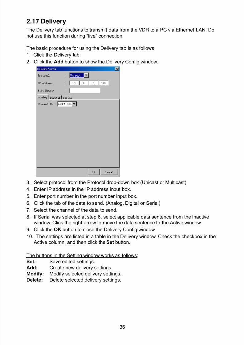
8102019 Ome44376d Vr3000 Mainte Cof26amp3bmol
httpslidepdfcomreaderfullome44376d-vr3000-mainte-cof26amp3bmol 3857
36
217 Delivery
The Delivery tab functions to transmit data from the VDR to a PC via Ethernet LAN Do
not use this function during live connection
The basic procedure for using the Delivery tab is as follows
1 Click the Delivery tab
2 Click the Add button to show the Delivery Config window
3 Select protocol from the Protocol drop-down box (Unicast or Multicast)
4 Enter IP address in the IP address input box
5 Enter port number in the port number input box
6 Click the tab of the data to send (Analog Digital or Serial)
7 Select the channel of the data to send
8 If Serial was selected at step 6 select applicable data sentence from the Inactivewindow Click the right arrow to move the data sentence to the Active window
9 Click the OK button to close the Delivery Config window
10 The settings are listed in a table in the Delivery window Check the checkbox in the
Active column and then click the Set button
The buttons in the Setting window works as follows
Set Save edited settings
Add Create new delivery settings
Modify Modify selected delivery settings
Delete Delete selected delivery settings
8102019 Ome44376d Vr3000 Mainte Cof26amp3bmol
httpslidepdfcomreaderfullome44376d-vr3000-mainte-cof26amp3bmol 3957
37
3 How to Back up Configuration DataThis chapter shows how to back up configuration data to various storage media
Configuration data can be opened with Word Pad or any text editor other than Notepad
31 How to Back up Configuration Data to the Startup CompactFlash (CF)
Back up data to the startup CF after setting the VDR Configuration data is created on the
CF as a configini file
Note When the error shown below occurs during the downloading or uploading of
configuration data check the connection of the DRU Backup HDD and CF and then
upload or download the configuration data again
[CONN] Download failed
[CONN] Could not upload config file
If error occurs again re-install the VDR Maintenance Viewer
Do the following to back up data to a CF
1 Set up parameters on the tabs referring to Chapter 2
2 Click the Maintenance menu
3 Select VDR Config Management
4 Click the Upload button
5 A confirmation box appears click the OK button to start uploading to the VDR
6 Click the Write button where the arrow connects between VDR and DRU BackupHDD
7 A confirmation window appears click the OK button to save the configuration data tothe DRU and Backup HDD
8102019 Ome44376d Vr3000 Mainte Cof26amp3bmol
httpslidepdfcomreaderfullome44376d-vr3000-mainte-cof26amp3bmol 4057
38
8 Click the Write button where the arrow connects between the VDR and CF
9 A confirmation window appears click the OK button to save the configuration data tothe startup CF
10 Check that the PC VDR DRU Backup HDD and CF share the same VDR configcode
32 How to Back up Configuration Data to a PC
Configuration data saved to the PC can be edited with Wordpad and shared with other
vessels For future service ease it is recommended to backup configuration data to the
PC and have the data on board the vessel Also it is recommended to upload this data to
Furuno SMS (Service Management System) If unable to upload to Furuno SMS please
contact the Service Center Furuno Japan
To back up configuration data to the PC do as follows
1 Set up parameters on the tabs referring to Chapter 2
2 Click the Maintenance menu
3 Select VDR Config Management
4 Click the Export to button
5 A confirmation window appears click the OK button
6 Select where to save the data enter file name then click the Open button
7 Confirm that back up file is in the location selected
33 How to restore the default settings
Click the Default button on the VDR Config Management window to restore the default
settings of the DRU Backup HDD CF and VDR Maintenance Viewer
8102019 Ome44376d Vr3000 Mainte Cof26amp3bmol
httpslidepdfcomreaderfullome44376d-vr3000-mainte-cof26amp3bmol 4157
39
4 How to Upload Configuration Datafrom a PCThe procedure below shows how to upload configuration from the PC to aVR-3000VR-3000S
1 Click the Maintenance menu
2 Select VDR Config Management
3 Click the Import from button
4 The Open window appears Select configuration data and then click the Open button
5 Click the Upload button to upload data to the VR-3000VR-3000S
6 Click the Write buttons to save data to the DRU backup HDD and CF
8102019 Ome44376d Vr3000 Mainte Cof26amp3bmol
httpslidepdfcomreaderfullome44376d-vr3000-mainte-cof26amp3bmol 4257
40
5 Media ManagementThe media management feature deletes data from recording media initialization the
system etc There are two method LAN connection and Direct connection The Direct
connection takes longer time than the LAN connection Basically use the LAN connection
method
Note Initialization or creation of recording media is not available when Source Select onthe Live Player V4 is selected to Backup HDD
51 Initialization
This section shows how to delete data from the recording media Configuration data is
not deleted After performing the software configuration delete the data from the DRU
and HDD
Do the following to delete data from the DRU (LAN connection)
1 Set the PlaybackCPU switch in the DCU to the CPU position
2 Use an Ethernet cross cable to connect the PC to J14 (DATA) in the DCU (See page5)
3 Open the Tool menu
4 Select Media Management to open the VDR Media Management window
5 Check that IP address shown in the ldquoLAN Connect to IPrdquo in VDR Media Table Area isthe same as the IP address access point
6 Select ldquoLAN Connect to IPrdquo in the VDR Media Table column
8102019 Ome44376d Vr3000 Mainte Cof26amp3bmol
httpslidepdfcomreaderfullome44376d-vr3000-mainte-cof26amp3bmol 4357
41
7 Click the Analyze button A list of recording media connected to the VDR appears
Put a checkmark in the checkbox of the Select column for the DRU in the Name columnNote If there are several flash memories in the DRU all flash memories are shownCheck all flash memories shown
8 Select ldquoDRU Initializerdquo from the Operation dropdown list in the Operation area
10 Click the Run button
Do the following to delete data from the DRU (Direct connection)
1 Start Live Player V4 software
2 Open the Tool menu and select Source Select Select Live from the pull-downmenu
3 Click the Alarm tab and open Alarm History
4 Set the PlaybackCPU switch in the DCU to the Playback position
5 Wait approx 10 minutes and confirm that Alarm 174 occurs on Alarm History of LivePlayer V4
6 Connect an IEEEE1394 cable between J6 in the DCU and the PC
7 Open the Tool menu
8 Select Media Management to show the VDR Media Management window
9 Select Direct in the VDR Media Table column
10 Click the Analyze button A list of recording media connected to the VDR appears
11 Put a checkmark in the checkbox of the Select column for the DRU in the Namecolumn
Note If there are several flash memories in the DRU all flash memories are shownCheck all flash memories shown
12 Select ldquoDRU Initializerdquo from the Operation dropdown list in the Operation area
13 Enter password in the password column
14 Click the RUN button
8102019 Ome44376d Vr3000 Mainte Cof26amp3bmol
httpslidepdfcomreaderfullome44376d-vr3000-mainte-cof26amp3bmol 4457
42
Delete data from the Backup HDD as follows (LAN connection)
1 Set the PlaybackCPU switch in the DCU to the CPU position
2 Check that an Ethernet cross cable is connected between J14 in the DCU and the PC
3 Open the Tool menu
4 Select Media Management to open the VDR Media Management window
5 Check that IP address shown in the LAN Connect to IP in VDR Media Table Area is
the same as the IP address access point6 Select LAN Connect to IP in the VDR Media Table column
7 Click the Analyze button
8 A list of recording media connected to the VDR appears
9 Put a checkmark in the box of the Select column for the Backup HDD in the Namecolumn Select ldquoBackup HDD Initializerdquo from the Operation dropdown list in theOperation area
10 Click the Run button
Delete data from the Backup HDD as follows (Direct connection)
1 Start Live Player V4 software
2 Open the Tool menu and select Source Select Select Live from the pull-downmenu
3 Click the Alarm tab and open Alarm History
4 Set the PlaybackCPU switch in the DCU to the Playback position
5 Wait approx 10 minutes and confirm that Alarm 174 occurs on Alarm History of LivePlayer V4
6 Connect an IEEE1394 cable between J6 in the DCU and the PC
7 Open the Tool menu
8 Select Media Management to open the VDR Media Management window9 Select Direct in the VDR Media Table window
10 Click the Analyze button A list of recording media connected to the VDR appears
11 Put a checkmark in the check box of the Select column for the Backup HDD in theName column Select ldquoBackup HDD Initializerdquo from the Operation dropdown list in theOperation area
12 Enter password
13 Click the Run button
8102019 Ome44376d Vr3000 Mainte Cof26amp3bmol
httpslidepdfcomreaderfullome44376d-vr3000-mainte-cof26amp3bmol 4557
43
52 CreationThe Creation feature initializes recording media
Note1 This feature deletes ALL configuration data Backup all VDR configuration data
Note2 When you initialize medium that is a different format for the DRU or Backup HDDdelete all partitions with the disk management tool of Windows
Note3 When the Creation is failed try again If you can not initialize recording media tryunder condition as shown below
Do the Creation by the direct connection (When the Creation by the LAN
connection is failed)
Delete all partitions of the DRU or Backup HDD with the disk management tool of
Windows to do the Creation
If the Creation is still failed request service to repairreplace the DRU or Backup
HDD
Initialize the DRU as follows (LAN connection)
1 Set the PlaybackCPU switch in the DCU to the CPU position
2 Check that an Ethernet cross cable is connected between J14 in the DCU and the PC
3 Open the Tool menu
4 Select Media Management to open the VDR Media Management window
5 Check that IP address shown in the LAN Connect to IP in VDR Media Table Area isthe same as the IP address access point
6 Check ldquoLAN Connect to IPrdquo in the VDR Media Table column
7 Click the Analyze button A list of recording media connected to the VDR appears
8 Put a checkmark in the box of the Select column for the DRU in the Name column
Select ldquoDRU Creationrdquo from the Operation dropdown list in the Operation area
9 Click the Run button
Initialize the Backup HDD as follows (LAN connection)
1 To format the Backup HDD place a checkmark in the Select column of the listedrecord media in the Name column of the VDR Media Management dialogue box
2 From the Operation drop down list of the Operation area select ldquoBackup HDDCreation (Radar) or ldquoBackup HDD Creationrdquo
Two partition tools are available for the Backup HDD in the Media Management as
below
Backup HDD creation
This tool is used when the number of the SXGA video signal connected to the BackupHDD is the same as the DRU The same partition is created on both DRU and HDD
(1) When two SXGA video signals are recorded onto the HDD while 9-GB DRU isconnected
(2) When an SXGA video signal is recorded onto the HDD while 6-GB DRU isconnected
Backup HDD creation (radar)
This tool is used when two SXGA video signals are recorded onto the HDD with 6-GB
DRU connected The HDD has an area (radar) to record the second radar signal inaddition to the same partition as the DRU This tool cannot be used when 9-GB DRUis connected
3 Press the Run Button
8102019 Ome44376d Vr3000 Mainte Cof26amp3bmol
httpslidepdfcomreaderfullome44376d-vr3000-mainte-cof26amp3bmol 4657
44
Initialize the DRU as follows (Direct connection)
1 Start Live Player V4 software
2 Open the Tool menu and select Source Select Select Live from the pull-downmenu
3 Click the Alarm tab and open Alarm History
4 Set the PlaybackCPU switch in the DCU to the Playback position
5 Wait approx 10 minutes and confirm that Alarm 174 occurs on Alarm History of LivePlayer V4
6 Connect an IEEE1394 cable between J6 in the DCU and the PC
7 Open the Tool menu
8 Select Media Management to open the VDR Media Management window
9 Select Direct in the VDR Media Table window
10 Click the Analyze button A list of recording media connected to the VDR appears
11 Put a checkmark in the box of the Select column for the DRU and the desiredrecording media in the Name column In the Operation dropdown list of the Operationarea select ldquoDRU Creationrdquo
12 Enter password in the password column
13 Click the Run button
Initialize the Backup HDD as follows (Direct Connection)
1 To format the Backup HDD place a checkmark in the Select column of the listedrecord media in the Name column of the VDR Media Management dialogue box
2 From the Operation column of the Operation area select ldquoBackup HDD Creation(Radar) or ldquoBackup HDD Creationrdquo
Backup HDD creation
This tool is used when the number of the SXGA video signal connected to the BackupHDD is the same as the DRU The same partition is created on both DRU and HDD
(1) When two SXGA video signals are recorded onto the HDD while 9-GB DRU is
connected
(2) When an SXGA video signal is recorded onto the HDD while 6-GB DRU is
connected
Backup HDD creation (radar)
This tool is used when two SXGA video signals are recorded onto the HDD with 6-GBDRU connected The HDD has an area (radar) to record the second radar signal inaddition to the same partition as the DRU This tool cannot be used when 9-GB DRUis connected
3 Enter the password in the Password column
4 Press the Run Button
8102019 Ome44376d Vr3000 Mainte Cof26amp3bmol
httpslidepdfcomreaderfullome44376d-vr3000-mainte-cof26amp3bmol 4757
45
53 How to Enable Recording Area on the Backup HDD
This function enables writing over a recording area To prevent falsification of data all
recording areas must be saved otherwise this function is disabled To use this function push
the SAVE button Save the data before doing this procedure
Note Software version 135 or higher can enable writing over a recording area even if
all recording areas are not saved
Recording enable (LAN connection)
1 Set the PlaybackCPU switch in the DCU to the CPU position
2 Check that an Ethernet cross cable is connected between J14 in the DCU and the PC
3 Open the Tool menu
4 Select Media Management to open the VDR Media Management window
5 Check that IP address shown in the ldquoLAN Connect to IPrdquo in VDR Media Table Area isthe same as the IP address access point
6 Select ldquoLAN Connect to IPrdquo in the VDR Media Table column7 Click the Analyze button A list of recording media connected to the VDR appears
8 Put a checkmark in the box of the Select column for the Backup HDD in the Namecolumn
9 Select ldquoBackup HDD Recording Area Enablerdquo from the Operation dropdown list in theOperation area
10 Click the Run button
Recording enable (Direct connection)
1 Start Live Player V4 software
2 Open the Tool menu and select Source Select Select Live from the pull-down menu3 Click the Alarm tab and open Alarm History
4 Set the PlaybackCPU switch in the DCU to the Playback position
5 Wait approx 10 minutes and confirm that Alarm 174 occurs on Alarm History of LivePlayer V4
6 Connect an IEEE1394 cable between J6 in the DCU and the PC
7 Open the Tool menu
8 Select Media Management to open the VDR Media Management window
9 Select Direct in the VDR Media Table window
10 Click the Analyze button A list of recording media connected to the VDR appears11 Put a checkmark in the box of the Select column for the Backup HDD in the Name
column
12 Select ldquoBackup HDD Recording Area Enablerdquo from the Operation dropdown list in theOperation area
13 Enter password
14 Click the Run button
8102019 Ome44376d Vr3000 Mainte Cof26amp3bmol
httpslidepdfcomreaderfullome44376d-vr3000-mainte-cof26amp3bmol 4857
46
6 Other Functions
61 Software Management
The software download feature downloads VDR system software to the PC
To download software
1 Click the Maintenance menu
2 From the Software Management menu click Software Download to show theSoftware Download window
3 Enter the IP address 1000100 in the IP address box in the Update Server area
4 Click the Download Software button
5 The confirmation window appears click the OK button
The Software Backup Execute window shows the results of the download
Software is downloaded to C Program Files VDR Viewer Viewer Backup The software file
name is vdrtar
To Update Software
VDR system program version 16x can update the software with the procedure shownbelow
Note Do not update the file downloaded in procedures above
1 Click the Maintenance menu
2 From the Software Management menu click Software Upload to show the SoftwareUpload area
3 Click the Select button to show the Open window
4 Select update file (vdrtar) and click the Open button
8102019 Ome44376d Vr3000 Mainte Cof26amp3bmol
httpslidepdfcomreaderfullome44376d-vr3000-mainte-cof26amp3bmol 4957
47
5 Check the displayed Software information is correct
6 Enter the IP address 1000100 in the IP address box in the Update Server area
7 Enter password
8 Click the Update button
After the updating is completed the VDR is automatically restarted
Note Click the Restore button on the Software Update window to restore previoussoftware version This feature is available after updating the software
62 Password Management
The password can be changed for a serviceman to access the equipment Contact
FURUNO to get the default password to use during installation
Serviceman password
1 Click the Maintenance menu2 Select Change Serviceman Password from Password Management to show the
Change Serviceman Password window
3 Enter current password in the Old Password box
4 Enter the new password in the New Password box of the Change Password area
5 Enter new password again in the Confirm New Password box
6 Click the OK button
Audio password
The audio password set at the VDR Maintenance Viewer can be removed to enable
audio access without password1 Click the Maintenance menu
2 Select Change Audio Password from Password Management to show the Change Audio Password window
3 The confirmation window appears click the OK button
8102019 Ome44376d Vr3000 Mainte Cof26amp3bmol
httpslidepdfcomreaderfullome44376d-vr3000-mainte-cof26amp3bmol 5057
48
63 Record ComparisonThe integrity of the DRU and Backup HDD recordings can be compared This function isused by the RampD engineer for debugging
Follow the procedure as shown below
1 Click the Maintenance menu2 Select Record Comparison to show the Record Comparison window
The results are shown every 15 seconds in the Record Comparison window
8102019 Ome44376d Vr3000 Mainte Cof26amp3bmol
httpslidepdfcomreaderfullome44376d-vr3000-mainte-cof26amp3bmol 5157
49
64 Software History
This section shows you to save and configure software history (communications record)
How to save software history
Note When the error dialog appears while saving the software history restart the VDR
Maintenance Viewer
1 Click the Maintenance menu
2 Select Software History Collect
3 Click the Select button The Open dialog box appears
4 Select where to save the data then click the Open button
5 Select desired save condition then click the OK buttonNone No savingAt Once Save the software history manually Saving begins as soon as the OK button is clickedPeriodic For debugging Do not use otherwise The intervals are 30 sec 60 secand 120 secAlarm Detection For debugging Do not use otherwise Software history is savedwhen specified alarm is released Enter alarm number
How to configure software communications record
The RampD engineer uses this function for debugging Do not do this procedure unless
required Malfunction can result
1 Click the Maintenance menu
2 Select Software History Config
3 Do the followingProcess Select the type of communications record to save ALL saves allcommunications records
Detail Hide or show detailed information4 Click the Send button
8102019 Ome44376d Vr3000 Mainte Cof26amp3bmol
httpslidepdfcomreaderfullome44376d-vr3000-mainte-cof26amp3bmol 5257
50
65 Easy SetupThis feature sets equipment settings in batch and creates a data file of those settings
Default template The default template is created with the settings entered at installation
1 Click the Maintenance menu
2 Select Easy Setup to show the Template Selection window
3 Select Default Template
4 Click the Start button to show the Easy Setup window
5 Right click the channels (Radar Audio Digital Serial Analog) then select Edit toshow the Equipment Selection window
6 From the Equipment Directory window select equipment connected to the selectedchannel and then click the OK button
7 Repeat steps 5 and 6 to select equipment settings for each channel
8 Click the Save button in the Easy Setup window to show the Save window
9 Select where to save the file and enter file name
10 Click the Save button
8102019 Ome44376d Vr3000 Mainte Cof26amp3bmol
httpslidepdfcomreaderfullome44376d-vr3000-mainte-cof26amp3bmol 5357
51
Specific template Use a file already created
1 Click the Maintenance menu
2 Select Easy Setup to show the Template Selection window
3 Check Specified Template
4 Click the Select button and then select the file to edit
5 Click the Start button to show the Easy Setup window
6 Right click the channels (Radar Audio Digital Serial Analog) then select Edit toshow the Equipment Selection window
7 From the Equipment Directory window select equipment connected to the selectedchannel and then click the OK button
8 Repeat steps 6 and 7 to select equipment settings for each channel
9 Click the Save button in the Easy Setup window to show the Save window
10Select where to save the file and enter file name
11 Click the Save button
66 Equipment Management
This feature controls the import and export of equipment settings
Import data file
Import data files of equipment settings created in Easy Setup etc to the VDR
1 Click the Maintenance menu
2 Select Import from Equipment Management to show the Open window
3 Select the data file to import and click Open
Export data file
Export data files of equipment settings from the VDR to a PC
1 Click the Maintenance menu
2 Select Export from Equipment Management to show the Save window
3 Enter file name
4 Click the Save button
8102019 Ome44376d Vr3000 Mainte Cof26amp3bmol
httpslidepdfcomreaderfullome44376d-vr3000-mainte-cof26amp3bmol 5457
52
67 PC_RAP
This feature enables the same operation of the RAP (Remote Alarm Panel) from a PC
Select PC_RAP from the Tool menu to show the PC_RAP window
The buttons in the PC_RAP window function as shown below
SAVE Stop recording in the area where recording is currently being done
ACK Silence audio alarm
The PC_RAP display shows the following information with LEDs
RAP_LEDs Display the status of LEDs on the RAPSave The Save button blinks yellow when pushed When the 4 memory
areas have data recorded to them the Save button lights orange when
pushed
Normal Lights (green) where there are no unconfirmed or not restored
alarms
Error Flashes (red) for not confirmed alarm Lights (red) for unrestored
alarm
8102019 Ome44376d Vr3000 Mainte Cof26amp3bmol
httpslidepdfcomreaderfullome44376d-vr3000-mainte-cof26amp3bmol 5557
53
Backup HDD Information Display status of backup HDD
Selected Display current recording area and its status in green for
normal operation and in red for abnormal operation
Size Display capacity of backup HDD
Alarm area displays unconfirmed alarms
Time Display time alarm was generatedNumber Display number of alarm
Name Display name of alarm
Pending Alarm displays the unrestored alarms out of confirmed alarms only
Time Display time alarm was generated
Number Display number of alarm
Name Display name of alarm
8102019 Ome44376d Vr3000 Mainte Cof26amp3bmol
httpslidepdfcomreaderfullome44376d-vr3000-mainte-cof26amp3bmol 5657
54
68 Other
Status Monitor
The status monitor feature provides comprehensive data about the status of the VDR
From the menu bar click Toolgt Status Monitor to show the Status Monitor window
The buttons in the Status Monitor window work as shown below
Reload Settings for automatic refreshing of the status monitor
ON Turn automatic refresh OFF
OFF The Status Monitor is refreshed every five seconds
Save Available when Reload ON is selected The contents of the Status Monitor can be
saved to a text fileUpdate Update the Status Monitor display
Close Close the Status Monitor display
8102019 Ome44376d Vr3000 Mainte Cof26amp3bmol
httpslidepdfcomreaderfullome44376d-vr3000-mainte-cof26amp3bmol 5757
VDR Error List
This feature compiles all the errors shown on the RAP for easy reference
Access from MenugtToolgtVDR Error List
The VDR error list contains the following information
NO Display the number of the error
Title Display the name of the error
Detail Display details about the error
Exchange Check
This feature removes the alarms generated when replacing the DRU or backup HDD
Access MenugtToolgtExchange Check select either DRU or Backup HDD and click OK
Reboot
Reboot the VDR
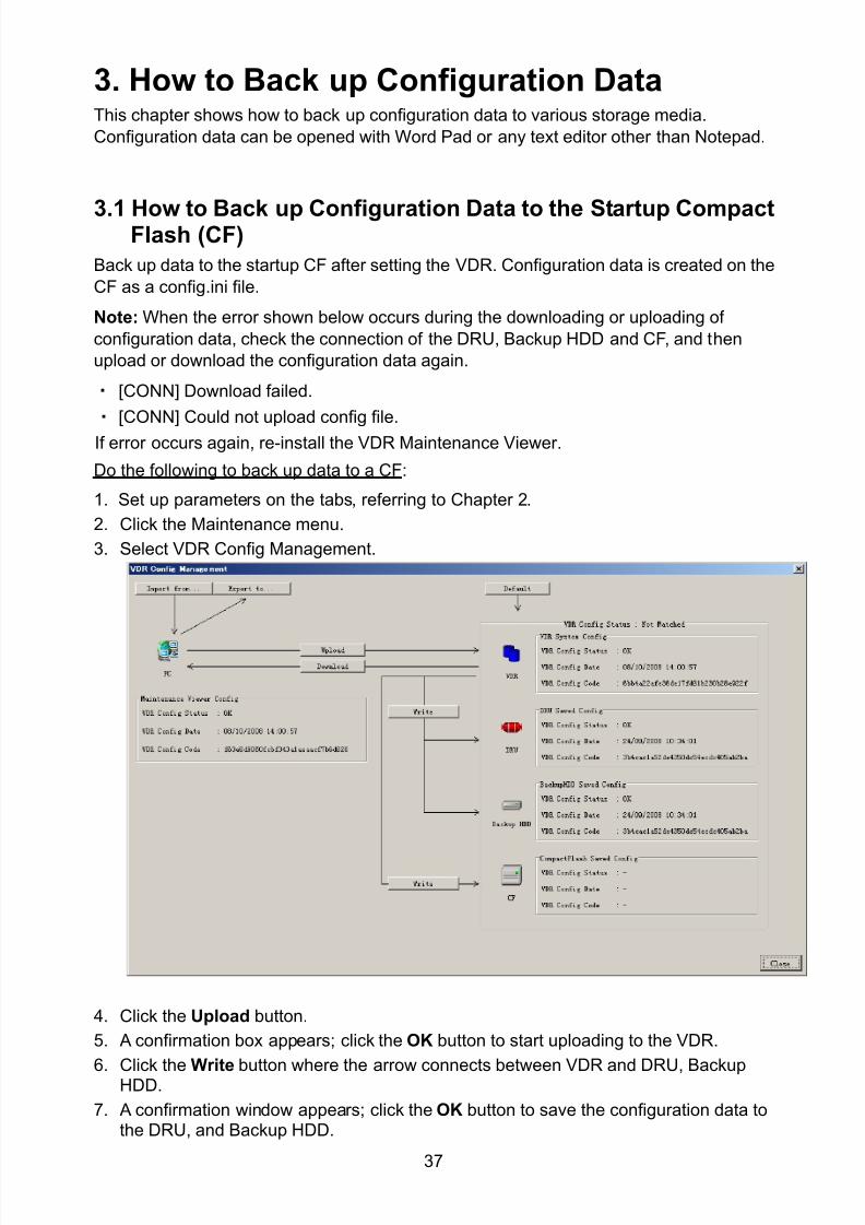
8102019 Ome44376d Vr3000 Mainte Cof26amp3bmol
httpslidepdfcomreaderfullome44376d-vr3000-mainte-cof26amp3bmol 3957
37
3 How to Back up Configuration DataThis chapter shows how to back up configuration data to various storage media
Configuration data can be opened with Word Pad or any text editor other than Notepad
31 How to Back up Configuration Data to the Startup CompactFlash (CF)
Back up data to the startup CF after setting the VDR Configuration data is created on the
CF as a configini file
Note When the error shown below occurs during the downloading or uploading of
configuration data check the connection of the DRU Backup HDD and CF and then
upload or download the configuration data again
[CONN] Download failed
[CONN] Could not upload config file
If error occurs again re-install the VDR Maintenance Viewer
Do the following to back up data to a CF
1 Set up parameters on the tabs referring to Chapter 2
2 Click the Maintenance menu
3 Select VDR Config Management
4 Click the Upload button
5 A confirmation box appears click the OK button to start uploading to the VDR
6 Click the Write button where the arrow connects between VDR and DRU BackupHDD
7 A confirmation window appears click the OK button to save the configuration data tothe DRU and Backup HDD
8102019 Ome44376d Vr3000 Mainte Cof26amp3bmol
httpslidepdfcomreaderfullome44376d-vr3000-mainte-cof26amp3bmol 4057
38
8 Click the Write button where the arrow connects between the VDR and CF
9 A confirmation window appears click the OK button to save the configuration data tothe startup CF
10 Check that the PC VDR DRU Backup HDD and CF share the same VDR configcode
32 How to Back up Configuration Data to a PC
Configuration data saved to the PC can be edited with Wordpad and shared with other
vessels For future service ease it is recommended to backup configuration data to the
PC and have the data on board the vessel Also it is recommended to upload this data to
Furuno SMS (Service Management System) If unable to upload to Furuno SMS please
contact the Service Center Furuno Japan
To back up configuration data to the PC do as follows
1 Set up parameters on the tabs referring to Chapter 2
2 Click the Maintenance menu
3 Select VDR Config Management
4 Click the Export to button
5 A confirmation window appears click the OK button
6 Select where to save the data enter file name then click the Open button
7 Confirm that back up file is in the location selected
33 How to restore the default settings
Click the Default button on the VDR Config Management window to restore the default
settings of the DRU Backup HDD CF and VDR Maintenance Viewer
8102019 Ome44376d Vr3000 Mainte Cof26amp3bmol
httpslidepdfcomreaderfullome44376d-vr3000-mainte-cof26amp3bmol 4157
39
4 How to Upload Configuration Datafrom a PCThe procedure below shows how to upload configuration from the PC to aVR-3000VR-3000S
1 Click the Maintenance menu
2 Select VDR Config Management
3 Click the Import from button
4 The Open window appears Select configuration data and then click the Open button
5 Click the Upload button to upload data to the VR-3000VR-3000S
6 Click the Write buttons to save data to the DRU backup HDD and CF
8102019 Ome44376d Vr3000 Mainte Cof26amp3bmol
httpslidepdfcomreaderfullome44376d-vr3000-mainte-cof26amp3bmol 4257
40
5 Media ManagementThe media management feature deletes data from recording media initialization the
system etc There are two method LAN connection and Direct connection The Direct
connection takes longer time than the LAN connection Basically use the LAN connection
method
Note Initialization or creation of recording media is not available when Source Select onthe Live Player V4 is selected to Backup HDD
51 Initialization
This section shows how to delete data from the recording media Configuration data is
not deleted After performing the software configuration delete the data from the DRU
and HDD
Do the following to delete data from the DRU (LAN connection)
1 Set the PlaybackCPU switch in the DCU to the CPU position
2 Use an Ethernet cross cable to connect the PC to J14 (DATA) in the DCU (See page5)
3 Open the Tool menu
4 Select Media Management to open the VDR Media Management window
5 Check that IP address shown in the ldquoLAN Connect to IPrdquo in VDR Media Table Area isthe same as the IP address access point
6 Select ldquoLAN Connect to IPrdquo in the VDR Media Table column
8102019 Ome44376d Vr3000 Mainte Cof26amp3bmol
httpslidepdfcomreaderfullome44376d-vr3000-mainte-cof26amp3bmol 4357
41
7 Click the Analyze button A list of recording media connected to the VDR appears
Put a checkmark in the checkbox of the Select column for the DRU in the Name columnNote If there are several flash memories in the DRU all flash memories are shownCheck all flash memories shown
8 Select ldquoDRU Initializerdquo from the Operation dropdown list in the Operation area
10 Click the Run button
Do the following to delete data from the DRU (Direct connection)
1 Start Live Player V4 software
2 Open the Tool menu and select Source Select Select Live from the pull-downmenu
3 Click the Alarm tab and open Alarm History
4 Set the PlaybackCPU switch in the DCU to the Playback position
5 Wait approx 10 minutes and confirm that Alarm 174 occurs on Alarm History of LivePlayer V4
6 Connect an IEEEE1394 cable between J6 in the DCU and the PC
7 Open the Tool menu
8 Select Media Management to show the VDR Media Management window
9 Select Direct in the VDR Media Table column
10 Click the Analyze button A list of recording media connected to the VDR appears
11 Put a checkmark in the checkbox of the Select column for the DRU in the Namecolumn
Note If there are several flash memories in the DRU all flash memories are shownCheck all flash memories shown
12 Select ldquoDRU Initializerdquo from the Operation dropdown list in the Operation area
13 Enter password in the password column
14 Click the RUN button
8102019 Ome44376d Vr3000 Mainte Cof26amp3bmol
httpslidepdfcomreaderfullome44376d-vr3000-mainte-cof26amp3bmol 4457
42
Delete data from the Backup HDD as follows (LAN connection)
1 Set the PlaybackCPU switch in the DCU to the CPU position
2 Check that an Ethernet cross cable is connected between J14 in the DCU and the PC
3 Open the Tool menu
4 Select Media Management to open the VDR Media Management window
5 Check that IP address shown in the LAN Connect to IP in VDR Media Table Area is
the same as the IP address access point6 Select LAN Connect to IP in the VDR Media Table column
7 Click the Analyze button
8 A list of recording media connected to the VDR appears
9 Put a checkmark in the box of the Select column for the Backup HDD in the Namecolumn Select ldquoBackup HDD Initializerdquo from the Operation dropdown list in theOperation area
10 Click the Run button
Delete data from the Backup HDD as follows (Direct connection)
1 Start Live Player V4 software
2 Open the Tool menu and select Source Select Select Live from the pull-downmenu
3 Click the Alarm tab and open Alarm History
4 Set the PlaybackCPU switch in the DCU to the Playback position
5 Wait approx 10 minutes and confirm that Alarm 174 occurs on Alarm History of LivePlayer V4
6 Connect an IEEE1394 cable between J6 in the DCU and the PC
7 Open the Tool menu
8 Select Media Management to open the VDR Media Management window9 Select Direct in the VDR Media Table window
10 Click the Analyze button A list of recording media connected to the VDR appears
11 Put a checkmark in the check box of the Select column for the Backup HDD in theName column Select ldquoBackup HDD Initializerdquo from the Operation dropdown list in theOperation area
12 Enter password
13 Click the Run button
8102019 Ome44376d Vr3000 Mainte Cof26amp3bmol
httpslidepdfcomreaderfullome44376d-vr3000-mainte-cof26amp3bmol 4557
43
52 CreationThe Creation feature initializes recording media
Note1 This feature deletes ALL configuration data Backup all VDR configuration data
Note2 When you initialize medium that is a different format for the DRU or Backup HDDdelete all partitions with the disk management tool of Windows
Note3 When the Creation is failed try again If you can not initialize recording media tryunder condition as shown below
Do the Creation by the direct connection (When the Creation by the LAN
connection is failed)
Delete all partitions of the DRU or Backup HDD with the disk management tool of
Windows to do the Creation
If the Creation is still failed request service to repairreplace the DRU or Backup
HDD
Initialize the DRU as follows (LAN connection)
1 Set the PlaybackCPU switch in the DCU to the CPU position
2 Check that an Ethernet cross cable is connected between J14 in the DCU and the PC
3 Open the Tool menu
4 Select Media Management to open the VDR Media Management window
5 Check that IP address shown in the LAN Connect to IP in VDR Media Table Area isthe same as the IP address access point
6 Check ldquoLAN Connect to IPrdquo in the VDR Media Table column
7 Click the Analyze button A list of recording media connected to the VDR appears
8 Put a checkmark in the box of the Select column for the DRU in the Name column
Select ldquoDRU Creationrdquo from the Operation dropdown list in the Operation area
9 Click the Run button
Initialize the Backup HDD as follows (LAN connection)
1 To format the Backup HDD place a checkmark in the Select column of the listedrecord media in the Name column of the VDR Media Management dialogue box
2 From the Operation drop down list of the Operation area select ldquoBackup HDDCreation (Radar) or ldquoBackup HDD Creationrdquo
Two partition tools are available for the Backup HDD in the Media Management as
below
Backup HDD creation
This tool is used when the number of the SXGA video signal connected to the BackupHDD is the same as the DRU The same partition is created on both DRU and HDD
(1) When two SXGA video signals are recorded onto the HDD while 9-GB DRU isconnected
(2) When an SXGA video signal is recorded onto the HDD while 6-GB DRU isconnected
Backup HDD creation (radar)
This tool is used when two SXGA video signals are recorded onto the HDD with 6-GB
DRU connected The HDD has an area (radar) to record the second radar signal inaddition to the same partition as the DRU This tool cannot be used when 9-GB DRUis connected
3 Press the Run Button
8102019 Ome44376d Vr3000 Mainte Cof26amp3bmol
httpslidepdfcomreaderfullome44376d-vr3000-mainte-cof26amp3bmol 4657
44
Initialize the DRU as follows (Direct connection)
1 Start Live Player V4 software
2 Open the Tool menu and select Source Select Select Live from the pull-downmenu
3 Click the Alarm tab and open Alarm History
4 Set the PlaybackCPU switch in the DCU to the Playback position
5 Wait approx 10 minutes and confirm that Alarm 174 occurs on Alarm History of LivePlayer V4
6 Connect an IEEE1394 cable between J6 in the DCU and the PC
7 Open the Tool menu
8 Select Media Management to open the VDR Media Management window
9 Select Direct in the VDR Media Table window
10 Click the Analyze button A list of recording media connected to the VDR appears
11 Put a checkmark in the box of the Select column for the DRU and the desiredrecording media in the Name column In the Operation dropdown list of the Operationarea select ldquoDRU Creationrdquo
12 Enter password in the password column
13 Click the Run button
Initialize the Backup HDD as follows (Direct Connection)
1 To format the Backup HDD place a checkmark in the Select column of the listedrecord media in the Name column of the VDR Media Management dialogue box
2 From the Operation column of the Operation area select ldquoBackup HDD Creation(Radar) or ldquoBackup HDD Creationrdquo
Backup HDD creation
This tool is used when the number of the SXGA video signal connected to the BackupHDD is the same as the DRU The same partition is created on both DRU and HDD
(1) When two SXGA video signals are recorded onto the HDD while 9-GB DRU is
connected
(2) When an SXGA video signal is recorded onto the HDD while 6-GB DRU is
connected
Backup HDD creation (radar)
This tool is used when two SXGA video signals are recorded onto the HDD with 6-GBDRU connected The HDD has an area (radar) to record the second radar signal inaddition to the same partition as the DRU This tool cannot be used when 9-GB DRUis connected
3 Enter the password in the Password column
4 Press the Run Button
8102019 Ome44376d Vr3000 Mainte Cof26amp3bmol
httpslidepdfcomreaderfullome44376d-vr3000-mainte-cof26amp3bmol 4757
45
53 How to Enable Recording Area on the Backup HDD
This function enables writing over a recording area To prevent falsification of data all
recording areas must be saved otherwise this function is disabled To use this function push
the SAVE button Save the data before doing this procedure
Note Software version 135 or higher can enable writing over a recording area even if
all recording areas are not saved
Recording enable (LAN connection)
1 Set the PlaybackCPU switch in the DCU to the CPU position
2 Check that an Ethernet cross cable is connected between J14 in the DCU and the PC
3 Open the Tool menu
4 Select Media Management to open the VDR Media Management window
5 Check that IP address shown in the ldquoLAN Connect to IPrdquo in VDR Media Table Area isthe same as the IP address access point
6 Select ldquoLAN Connect to IPrdquo in the VDR Media Table column7 Click the Analyze button A list of recording media connected to the VDR appears
8 Put a checkmark in the box of the Select column for the Backup HDD in the Namecolumn
9 Select ldquoBackup HDD Recording Area Enablerdquo from the Operation dropdown list in theOperation area
10 Click the Run button
Recording enable (Direct connection)
1 Start Live Player V4 software
2 Open the Tool menu and select Source Select Select Live from the pull-down menu3 Click the Alarm tab and open Alarm History
4 Set the PlaybackCPU switch in the DCU to the Playback position
5 Wait approx 10 minutes and confirm that Alarm 174 occurs on Alarm History of LivePlayer V4
6 Connect an IEEE1394 cable between J6 in the DCU and the PC
7 Open the Tool menu
8 Select Media Management to open the VDR Media Management window
9 Select Direct in the VDR Media Table window
10 Click the Analyze button A list of recording media connected to the VDR appears11 Put a checkmark in the box of the Select column for the Backup HDD in the Name
column
12 Select ldquoBackup HDD Recording Area Enablerdquo from the Operation dropdown list in theOperation area
13 Enter password
14 Click the Run button
8102019 Ome44376d Vr3000 Mainte Cof26amp3bmol
httpslidepdfcomreaderfullome44376d-vr3000-mainte-cof26amp3bmol 4857
46
6 Other Functions
61 Software Management
The software download feature downloads VDR system software to the PC
To download software
1 Click the Maintenance menu
2 From the Software Management menu click Software Download to show theSoftware Download window
3 Enter the IP address 1000100 in the IP address box in the Update Server area
4 Click the Download Software button
5 The confirmation window appears click the OK button
The Software Backup Execute window shows the results of the download
Software is downloaded to C Program Files VDR Viewer Viewer Backup The software file
name is vdrtar
To Update Software
VDR system program version 16x can update the software with the procedure shownbelow
Note Do not update the file downloaded in procedures above
1 Click the Maintenance menu
2 From the Software Management menu click Software Upload to show the SoftwareUpload area
3 Click the Select button to show the Open window
4 Select update file (vdrtar) and click the Open button
8102019 Ome44376d Vr3000 Mainte Cof26amp3bmol
httpslidepdfcomreaderfullome44376d-vr3000-mainte-cof26amp3bmol 4957
47
5 Check the displayed Software information is correct
6 Enter the IP address 1000100 in the IP address box in the Update Server area
7 Enter password
8 Click the Update button
After the updating is completed the VDR is automatically restarted
Note Click the Restore button on the Software Update window to restore previoussoftware version This feature is available after updating the software
62 Password Management
The password can be changed for a serviceman to access the equipment Contact
FURUNO to get the default password to use during installation
Serviceman password
1 Click the Maintenance menu2 Select Change Serviceman Password from Password Management to show the
Change Serviceman Password window
3 Enter current password in the Old Password box
4 Enter the new password in the New Password box of the Change Password area
5 Enter new password again in the Confirm New Password box
6 Click the OK button
Audio password
The audio password set at the VDR Maintenance Viewer can be removed to enable
audio access without password1 Click the Maintenance menu
2 Select Change Audio Password from Password Management to show the Change Audio Password window
3 The confirmation window appears click the OK button
8102019 Ome44376d Vr3000 Mainte Cof26amp3bmol
httpslidepdfcomreaderfullome44376d-vr3000-mainte-cof26amp3bmol 5057
48
63 Record ComparisonThe integrity of the DRU and Backup HDD recordings can be compared This function isused by the RampD engineer for debugging
Follow the procedure as shown below
1 Click the Maintenance menu2 Select Record Comparison to show the Record Comparison window
The results are shown every 15 seconds in the Record Comparison window
8102019 Ome44376d Vr3000 Mainte Cof26amp3bmol
httpslidepdfcomreaderfullome44376d-vr3000-mainte-cof26amp3bmol 5157
49
64 Software History
This section shows you to save and configure software history (communications record)
How to save software history
Note When the error dialog appears while saving the software history restart the VDR
Maintenance Viewer
1 Click the Maintenance menu
2 Select Software History Collect
3 Click the Select button The Open dialog box appears
4 Select where to save the data then click the Open button
5 Select desired save condition then click the OK buttonNone No savingAt Once Save the software history manually Saving begins as soon as the OK button is clickedPeriodic For debugging Do not use otherwise The intervals are 30 sec 60 secand 120 secAlarm Detection For debugging Do not use otherwise Software history is savedwhen specified alarm is released Enter alarm number
How to configure software communications record
The RampD engineer uses this function for debugging Do not do this procedure unless
required Malfunction can result
1 Click the Maintenance menu
2 Select Software History Config
3 Do the followingProcess Select the type of communications record to save ALL saves allcommunications records
Detail Hide or show detailed information4 Click the Send button
8102019 Ome44376d Vr3000 Mainte Cof26amp3bmol
httpslidepdfcomreaderfullome44376d-vr3000-mainte-cof26amp3bmol 5257
50
65 Easy SetupThis feature sets equipment settings in batch and creates a data file of those settings
Default template The default template is created with the settings entered at installation
1 Click the Maintenance menu
2 Select Easy Setup to show the Template Selection window
3 Select Default Template
4 Click the Start button to show the Easy Setup window
5 Right click the channels (Radar Audio Digital Serial Analog) then select Edit toshow the Equipment Selection window
6 From the Equipment Directory window select equipment connected to the selectedchannel and then click the OK button
7 Repeat steps 5 and 6 to select equipment settings for each channel
8 Click the Save button in the Easy Setup window to show the Save window
9 Select where to save the file and enter file name
10 Click the Save button
8102019 Ome44376d Vr3000 Mainte Cof26amp3bmol
httpslidepdfcomreaderfullome44376d-vr3000-mainte-cof26amp3bmol 5357
51
Specific template Use a file already created
1 Click the Maintenance menu
2 Select Easy Setup to show the Template Selection window
3 Check Specified Template
4 Click the Select button and then select the file to edit
5 Click the Start button to show the Easy Setup window
6 Right click the channels (Radar Audio Digital Serial Analog) then select Edit toshow the Equipment Selection window
7 From the Equipment Directory window select equipment connected to the selectedchannel and then click the OK button
8 Repeat steps 6 and 7 to select equipment settings for each channel
9 Click the Save button in the Easy Setup window to show the Save window
10Select where to save the file and enter file name
11 Click the Save button
66 Equipment Management
This feature controls the import and export of equipment settings
Import data file
Import data files of equipment settings created in Easy Setup etc to the VDR
1 Click the Maintenance menu
2 Select Import from Equipment Management to show the Open window
3 Select the data file to import and click Open
Export data file
Export data files of equipment settings from the VDR to a PC
1 Click the Maintenance menu
2 Select Export from Equipment Management to show the Save window
3 Enter file name
4 Click the Save button
8102019 Ome44376d Vr3000 Mainte Cof26amp3bmol
httpslidepdfcomreaderfullome44376d-vr3000-mainte-cof26amp3bmol 5457
52
67 PC_RAP
This feature enables the same operation of the RAP (Remote Alarm Panel) from a PC
Select PC_RAP from the Tool menu to show the PC_RAP window
The buttons in the PC_RAP window function as shown below
SAVE Stop recording in the area where recording is currently being done
ACK Silence audio alarm
The PC_RAP display shows the following information with LEDs
RAP_LEDs Display the status of LEDs on the RAPSave The Save button blinks yellow when pushed When the 4 memory
areas have data recorded to them the Save button lights orange when
pushed
Normal Lights (green) where there are no unconfirmed or not restored
alarms
Error Flashes (red) for not confirmed alarm Lights (red) for unrestored
alarm
8102019 Ome44376d Vr3000 Mainte Cof26amp3bmol
httpslidepdfcomreaderfullome44376d-vr3000-mainte-cof26amp3bmol 5557
53
Backup HDD Information Display status of backup HDD
Selected Display current recording area and its status in green for
normal operation and in red for abnormal operation
Size Display capacity of backup HDD
Alarm area displays unconfirmed alarms
Time Display time alarm was generatedNumber Display number of alarm
Name Display name of alarm
Pending Alarm displays the unrestored alarms out of confirmed alarms only
Time Display time alarm was generated
Number Display number of alarm
Name Display name of alarm
8102019 Ome44376d Vr3000 Mainte Cof26amp3bmol
httpslidepdfcomreaderfullome44376d-vr3000-mainte-cof26amp3bmol 5657
54
68 Other
Status Monitor
The status monitor feature provides comprehensive data about the status of the VDR
From the menu bar click Toolgt Status Monitor to show the Status Monitor window
The buttons in the Status Monitor window work as shown below
Reload Settings for automatic refreshing of the status monitor
ON Turn automatic refresh OFF
OFF The Status Monitor is refreshed every five seconds
Save Available when Reload ON is selected The contents of the Status Monitor can be
saved to a text fileUpdate Update the Status Monitor display
Close Close the Status Monitor display
8102019 Ome44376d Vr3000 Mainte Cof26amp3bmol
httpslidepdfcomreaderfullome44376d-vr3000-mainte-cof26amp3bmol 5757
VDR Error List
This feature compiles all the errors shown on the RAP for easy reference
Access from MenugtToolgtVDR Error List
The VDR error list contains the following information
NO Display the number of the error
Title Display the name of the error
Detail Display details about the error
Exchange Check
This feature removes the alarms generated when replacing the DRU or backup HDD
Access MenugtToolgtExchange Check select either DRU or Backup HDD and click OK
Reboot
Reboot the VDR
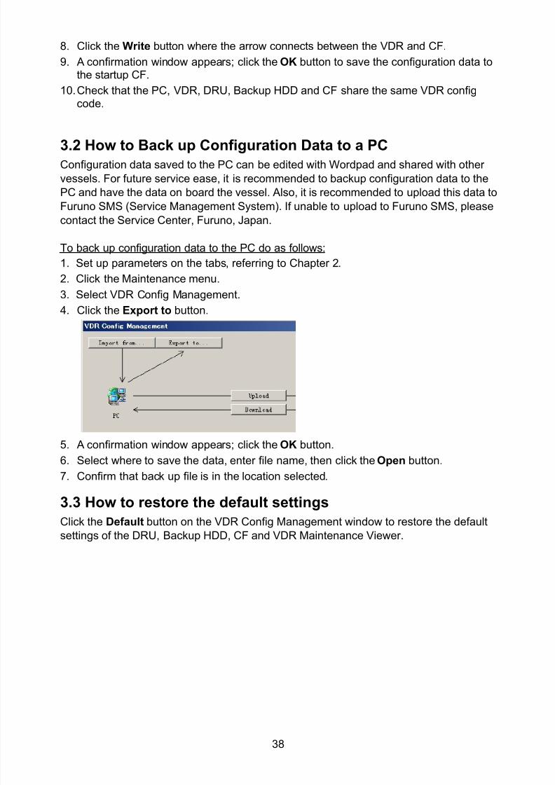
8102019 Ome44376d Vr3000 Mainte Cof26amp3bmol
httpslidepdfcomreaderfullome44376d-vr3000-mainte-cof26amp3bmol 4057
38
8 Click the Write button where the arrow connects between the VDR and CF
9 A confirmation window appears click the OK button to save the configuration data tothe startup CF
10 Check that the PC VDR DRU Backup HDD and CF share the same VDR configcode
32 How to Back up Configuration Data to a PC
Configuration data saved to the PC can be edited with Wordpad and shared with other
vessels For future service ease it is recommended to backup configuration data to the
PC and have the data on board the vessel Also it is recommended to upload this data to
Furuno SMS (Service Management System) If unable to upload to Furuno SMS please
contact the Service Center Furuno Japan
To back up configuration data to the PC do as follows
1 Set up parameters on the tabs referring to Chapter 2
2 Click the Maintenance menu
3 Select VDR Config Management
4 Click the Export to button
5 A confirmation window appears click the OK button
6 Select where to save the data enter file name then click the Open button
7 Confirm that back up file is in the location selected
33 How to restore the default settings
Click the Default button on the VDR Config Management window to restore the default
settings of the DRU Backup HDD CF and VDR Maintenance Viewer
8102019 Ome44376d Vr3000 Mainte Cof26amp3bmol
httpslidepdfcomreaderfullome44376d-vr3000-mainte-cof26amp3bmol 4157
39
4 How to Upload Configuration Datafrom a PCThe procedure below shows how to upload configuration from the PC to aVR-3000VR-3000S
1 Click the Maintenance menu
2 Select VDR Config Management
3 Click the Import from button
4 The Open window appears Select configuration data and then click the Open button
5 Click the Upload button to upload data to the VR-3000VR-3000S
6 Click the Write buttons to save data to the DRU backup HDD and CF
8102019 Ome44376d Vr3000 Mainte Cof26amp3bmol
httpslidepdfcomreaderfullome44376d-vr3000-mainte-cof26amp3bmol 4257
40
5 Media ManagementThe media management feature deletes data from recording media initialization the
system etc There are two method LAN connection and Direct connection The Direct
connection takes longer time than the LAN connection Basically use the LAN connection
method
Note Initialization or creation of recording media is not available when Source Select onthe Live Player V4 is selected to Backup HDD
51 Initialization
This section shows how to delete data from the recording media Configuration data is
not deleted After performing the software configuration delete the data from the DRU
and HDD
Do the following to delete data from the DRU (LAN connection)
1 Set the PlaybackCPU switch in the DCU to the CPU position
2 Use an Ethernet cross cable to connect the PC to J14 (DATA) in the DCU (See page5)
3 Open the Tool menu
4 Select Media Management to open the VDR Media Management window
5 Check that IP address shown in the ldquoLAN Connect to IPrdquo in VDR Media Table Area isthe same as the IP address access point
6 Select ldquoLAN Connect to IPrdquo in the VDR Media Table column
8102019 Ome44376d Vr3000 Mainte Cof26amp3bmol
httpslidepdfcomreaderfullome44376d-vr3000-mainte-cof26amp3bmol 4357
41
7 Click the Analyze button A list of recording media connected to the VDR appears
Put a checkmark in the checkbox of the Select column for the DRU in the Name columnNote If there are several flash memories in the DRU all flash memories are shownCheck all flash memories shown
8 Select ldquoDRU Initializerdquo from the Operation dropdown list in the Operation area
10 Click the Run button
Do the following to delete data from the DRU (Direct connection)
1 Start Live Player V4 software
2 Open the Tool menu and select Source Select Select Live from the pull-downmenu
3 Click the Alarm tab and open Alarm History
4 Set the PlaybackCPU switch in the DCU to the Playback position
5 Wait approx 10 minutes and confirm that Alarm 174 occurs on Alarm History of LivePlayer V4
6 Connect an IEEEE1394 cable between J6 in the DCU and the PC
7 Open the Tool menu
8 Select Media Management to show the VDR Media Management window
9 Select Direct in the VDR Media Table column
10 Click the Analyze button A list of recording media connected to the VDR appears
11 Put a checkmark in the checkbox of the Select column for the DRU in the Namecolumn
Note If there are several flash memories in the DRU all flash memories are shownCheck all flash memories shown
12 Select ldquoDRU Initializerdquo from the Operation dropdown list in the Operation area
13 Enter password in the password column
14 Click the RUN button
8102019 Ome44376d Vr3000 Mainte Cof26amp3bmol
httpslidepdfcomreaderfullome44376d-vr3000-mainte-cof26amp3bmol 4457
42
Delete data from the Backup HDD as follows (LAN connection)
1 Set the PlaybackCPU switch in the DCU to the CPU position
2 Check that an Ethernet cross cable is connected between J14 in the DCU and the PC
3 Open the Tool menu
4 Select Media Management to open the VDR Media Management window
5 Check that IP address shown in the LAN Connect to IP in VDR Media Table Area is
the same as the IP address access point6 Select LAN Connect to IP in the VDR Media Table column
7 Click the Analyze button
8 A list of recording media connected to the VDR appears
9 Put a checkmark in the box of the Select column for the Backup HDD in the Namecolumn Select ldquoBackup HDD Initializerdquo from the Operation dropdown list in theOperation area
10 Click the Run button
Delete data from the Backup HDD as follows (Direct connection)
1 Start Live Player V4 software
2 Open the Tool menu and select Source Select Select Live from the pull-downmenu
3 Click the Alarm tab and open Alarm History
4 Set the PlaybackCPU switch in the DCU to the Playback position
5 Wait approx 10 minutes and confirm that Alarm 174 occurs on Alarm History of LivePlayer V4
6 Connect an IEEE1394 cable between J6 in the DCU and the PC
7 Open the Tool menu
8 Select Media Management to open the VDR Media Management window9 Select Direct in the VDR Media Table window
10 Click the Analyze button A list of recording media connected to the VDR appears
11 Put a checkmark in the check box of the Select column for the Backup HDD in theName column Select ldquoBackup HDD Initializerdquo from the Operation dropdown list in theOperation area
12 Enter password
13 Click the Run button
8102019 Ome44376d Vr3000 Mainte Cof26amp3bmol
httpslidepdfcomreaderfullome44376d-vr3000-mainte-cof26amp3bmol 4557
43
52 CreationThe Creation feature initializes recording media
Note1 This feature deletes ALL configuration data Backup all VDR configuration data
Note2 When you initialize medium that is a different format for the DRU or Backup HDDdelete all partitions with the disk management tool of Windows
Note3 When the Creation is failed try again If you can not initialize recording media tryunder condition as shown below
Do the Creation by the direct connection (When the Creation by the LAN
connection is failed)
Delete all partitions of the DRU or Backup HDD with the disk management tool of
Windows to do the Creation
If the Creation is still failed request service to repairreplace the DRU or Backup
HDD
Initialize the DRU as follows (LAN connection)
1 Set the PlaybackCPU switch in the DCU to the CPU position
2 Check that an Ethernet cross cable is connected between J14 in the DCU and the PC
3 Open the Tool menu
4 Select Media Management to open the VDR Media Management window
5 Check that IP address shown in the LAN Connect to IP in VDR Media Table Area isthe same as the IP address access point
6 Check ldquoLAN Connect to IPrdquo in the VDR Media Table column
7 Click the Analyze button A list of recording media connected to the VDR appears
8 Put a checkmark in the box of the Select column for the DRU in the Name column
Select ldquoDRU Creationrdquo from the Operation dropdown list in the Operation area
9 Click the Run button
Initialize the Backup HDD as follows (LAN connection)
1 To format the Backup HDD place a checkmark in the Select column of the listedrecord media in the Name column of the VDR Media Management dialogue box
2 From the Operation drop down list of the Operation area select ldquoBackup HDDCreation (Radar) or ldquoBackup HDD Creationrdquo
Two partition tools are available for the Backup HDD in the Media Management as
below
Backup HDD creation
This tool is used when the number of the SXGA video signal connected to the BackupHDD is the same as the DRU The same partition is created on both DRU and HDD
(1) When two SXGA video signals are recorded onto the HDD while 9-GB DRU isconnected
(2) When an SXGA video signal is recorded onto the HDD while 6-GB DRU isconnected
Backup HDD creation (radar)
This tool is used when two SXGA video signals are recorded onto the HDD with 6-GB
DRU connected The HDD has an area (radar) to record the second radar signal inaddition to the same partition as the DRU This tool cannot be used when 9-GB DRUis connected
3 Press the Run Button
8102019 Ome44376d Vr3000 Mainte Cof26amp3bmol
httpslidepdfcomreaderfullome44376d-vr3000-mainte-cof26amp3bmol 4657
44
Initialize the DRU as follows (Direct connection)
1 Start Live Player V4 software
2 Open the Tool menu and select Source Select Select Live from the pull-downmenu
3 Click the Alarm tab and open Alarm History
4 Set the PlaybackCPU switch in the DCU to the Playback position
5 Wait approx 10 minutes and confirm that Alarm 174 occurs on Alarm History of LivePlayer V4
6 Connect an IEEE1394 cable between J6 in the DCU and the PC
7 Open the Tool menu
8 Select Media Management to open the VDR Media Management window
9 Select Direct in the VDR Media Table window
10 Click the Analyze button A list of recording media connected to the VDR appears
11 Put a checkmark in the box of the Select column for the DRU and the desiredrecording media in the Name column In the Operation dropdown list of the Operationarea select ldquoDRU Creationrdquo
12 Enter password in the password column
13 Click the Run button
Initialize the Backup HDD as follows (Direct Connection)
1 To format the Backup HDD place a checkmark in the Select column of the listedrecord media in the Name column of the VDR Media Management dialogue box
2 From the Operation column of the Operation area select ldquoBackup HDD Creation(Radar) or ldquoBackup HDD Creationrdquo
Backup HDD creation
This tool is used when the number of the SXGA video signal connected to the BackupHDD is the same as the DRU The same partition is created on both DRU and HDD
(1) When two SXGA video signals are recorded onto the HDD while 9-GB DRU is
connected
(2) When an SXGA video signal is recorded onto the HDD while 6-GB DRU is
connected
Backup HDD creation (radar)
This tool is used when two SXGA video signals are recorded onto the HDD with 6-GBDRU connected The HDD has an area (radar) to record the second radar signal inaddition to the same partition as the DRU This tool cannot be used when 9-GB DRUis connected
3 Enter the password in the Password column
4 Press the Run Button
8102019 Ome44376d Vr3000 Mainte Cof26amp3bmol
httpslidepdfcomreaderfullome44376d-vr3000-mainte-cof26amp3bmol 4757
45
53 How to Enable Recording Area on the Backup HDD
This function enables writing over a recording area To prevent falsification of data all
recording areas must be saved otherwise this function is disabled To use this function push
the SAVE button Save the data before doing this procedure
Note Software version 135 or higher can enable writing over a recording area even if
all recording areas are not saved
Recording enable (LAN connection)
1 Set the PlaybackCPU switch in the DCU to the CPU position
2 Check that an Ethernet cross cable is connected between J14 in the DCU and the PC
3 Open the Tool menu
4 Select Media Management to open the VDR Media Management window
5 Check that IP address shown in the ldquoLAN Connect to IPrdquo in VDR Media Table Area isthe same as the IP address access point
6 Select ldquoLAN Connect to IPrdquo in the VDR Media Table column7 Click the Analyze button A list of recording media connected to the VDR appears
8 Put a checkmark in the box of the Select column for the Backup HDD in the Namecolumn
9 Select ldquoBackup HDD Recording Area Enablerdquo from the Operation dropdown list in theOperation area
10 Click the Run button
Recording enable (Direct connection)
1 Start Live Player V4 software
2 Open the Tool menu and select Source Select Select Live from the pull-down menu3 Click the Alarm tab and open Alarm History
4 Set the PlaybackCPU switch in the DCU to the Playback position
5 Wait approx 10 minutes and confirm that Alarm 174 occurs on Alarm History of LivePlayer V4
6 Connect an IEEE1394 cable between J6 in the DCU and the PC
7 Open the Tool menu
8 Select Media Management to open the VDR Media Management window
9 Select Direct in the VDR Media Table window
10 Click the Analyze button A list of recording media connected to the VDR appears11 Put a checkmark in the box of the Select column for the Backup HDD in the Name
column
12 Select ldquoBackup HDD Recording Area Enablerdquo from the Operation dropdown list in theOperation area
13 Enter password
14 Click the Run button
8102019 Ome44376d Vr3000 Mainte Cof26amp3bmol
httpslidepdfcomreaderfullome44376d-vr3000-mainte-cof26amp3bmol 4857
46
6 Other Functions
61 Software Management
The software download feature downloads VDR system software to the PC
To download software
1 Click the Maintenance menu
2 From the Software Management menu click Software Download to show theSoftware Download window
3 Enter the IP address 1000100 in the IP address box in the Update Server area
4 Click the Download Software button
5 The confirmation window appears click the OK button
The Software Backup Execute window shows the results of the download
Software is downloaded to C Program Files VDR Viewer Viewer Backup The software file
name is vdrtar
To Update Software
VDR system program version 16x can update the software with the procedure shownbelow
Note Do not update the file downloaded in procedures above
1 Click the Maintenance menu
2 From the Software Management menu click Software Upload to show the SoftwareUpload area
3 Click the Select button to show the Open window
4 Select update file (vdrtar) and click the Open button
8102019 Ome44376d Vr3000 Mainte Cof26amp3bmol
httpslidepdfcomreaderfullome44376d-vr3000-mainte-cof26amp3bmol 4957
47
5 Check the displayed Software information is correct
6 Enter the IP address 1000100 in the IP address box in the Update Server area
7 Enter password
8 Click the Update button
After the updating is completed the VDR is automatically restarted
Note Click the Restore button on the Software Update window to restore previoussoftware version This feature is available after updating the software
62 Password Management
The password can be changed for a serviceman to access the equipment Contact
FURUNO to get the default password to use during installation
Serviceman password
1 Click the Maintenance menu2 Select Change Serviceman Password from Password Management to show the
Change Serviceman Password window
3 Enter current password in the Old Password box
4 Enter the new password in the New Password box of the Change Password area
5 Enter new password again in the Confirm New Password box
6 Click the OK button
Audio password
The audio password set at the VDR Maintenance Viewer can be removed to enable
audio access without password1 Click the Maintenance menu
2 Select Change Audio Password from Password Management to show the Change Audio Password window
3 The confirmation window appears click the OK button
8102019 Ome44376d Vr3000 Mainte Cof26amp3bmol
httpslidepdfcomreaderfullome44376d-vr3000-mainte-cof26amp3bmol 5057
48
63 Record ComparisonThe integrity of the DRU and Backup HDD recordings can be compared This function isused by the RampD engineer for debugging
Follow the procedure as shown below
1 Click the Maintenance menu2 Select Record Comparison to show the Record Comparison window
The results are shown every 15 seconds in the Record Comparison window
8102019 Ome44376d Vr3000 Mainte Cof26amp3bmol
httpslidepdfcomreaderfullome44376d-vr3000-mainte-cof26amp3bmol 5157
49
64 Software History
This section shows you to save and configure software history (communications record)
How to save software history
Note When the error dialog appears while saving the software history restart the VDR
Maintenance Viewer
1 Click the Maintenance menu
2 Select Software History Collect
3 Click the Select button The Open dialog box appears
4 Select where to save the data then click the Open button
5 Select desired save condition then click the OK buttonNone No savingAt Once Save the software history manually Saving begins as soon as the OK button is clickedPeriodic For debugging Do not use otherwise The intervals are 30 sec 60 secand 120 secAlarm Detection For debugging Do not use otherwise Software history is savedwhen specified alarm is released Enter alarm number
How to configure software communications record
The RampD engineer uses this function for debugging Do not do this procedure unless
required Malfunction can result
1 Click the Maintenance menu
2 Select Software History Config
3 Do the followingProcess Select the type of communications record to save ALL saves allcommunications records
Detail Hide or show detailed information4 Click the Send button
8102019 Ome44376d Vr3000 Mainte Cof26amp3bmol
httpslidepdfcomreaderfullome44376d-vr3000-mainte-cof26amp3bmol 5257
50
65 Easy SetupThis feature sets equipment settings in batch and creates a data file of those settings
Default template The default template is created with the settings entered at installation
1 Click the Maintenance menu
2 Select Easy Setup to show the Template Selection window
3 Select Default Template
4 Click the Start button to show the Easy Setup window
5 Right click the channels (Radar Audio Digital Serial Analog) then select Edit toshow the Equipment Selection window
6 From the Equipment Directory window select equipment connected to the selectedchannel and then click the OK button
7 Repeat steps 5 and 6 to select equipment settings for each channel
8 Click the Save button in the Easy Setup window to show the Save window
9 Select where to save the file and enter file name
10 Click the Save button
8102019 Ome44376d Vr3000 Mainte Cof26amp3bmol
httpslidepdfcomreaderfullome44376d-vr3000-mainte-cof26amp3bmol 5357
51
Specific template Use a file already created
1 Click the Maintenance menu
2 Select Easy Setup to show the Template Selection window
3 Check Specified Template
4 Click the Select button and then select the file to edit
5 Click the Start button to show the Easy Setup window
6 Right click the channels (Radar Audio Digital Serial Analog) then select Edit toshow the Equipment Selection window
7 From the Equipment Directory window select equipment connected to the selectedchannel and then click the OK button
8 Repeat steps 6 and 7 to select equipment settings for each channel
9 Click the Save button in the Easy Setup window to show the Save window
10Select where to save the file and enter file name
11 Click the Save button
66 Equipment Management
This feature controls the import and export of equipment settings
Import data file
Import data files of equipment settings created in Easy Setup etc to the VDR
1 Click the Maintenance menu
2 Select Import from Equipment Management to show the Open window
3 Select the data file to import and click Open
Export data file
Export data files of equipment settings from the VDR to a PC
1 Click the Maintenance menu
2 Select Export from Equipment Management to show the Save window
3 Enter file name
4 Click the Save button
8102019 Ome44376d Vr3000 Mainte Cof26amp3bmol
httpslidepdfcomreaderfullome44376d-vr3000-mainte-cof26amp3bmol 5457
52
67 PC_RAP
This feature enables the same operation of the RAP (Remote Alarm Panel) from a PC
Select PC_RAP from the Tool menu to show the PC_RAP window
The buttons in the PC_RAP window function as shown below
SAVE Stop recording in the area where recording is currently being done
ACK Silence audio alarm
The PC_RAP display shows the following information with LEDs
RAP_LEDs Display the status of LEDs on the RAPSave The Save button blinks yellow when pushed When the 4 memory
areas have data recorded to them the Save button lights orange when
pushed
Normal Lights (green) where there are no unconfirmed or not restored
alarms
Error Flashes (red) for not confirmed alarm Lights (red) for unrestored
alarm
8102019 Ome44376d Vr3000 Mainte Cof26amp3bmol
httpslidepdfcomreaderfullome44376d-vr3000-mainte-cof26amp3bmol 5557
53
Backup HDD Information Display status of backup HDD
Selected Display current recording area and its status in green for
normal operation and in red for abnormal operation
Size Display capacity of backup HDD
Alarm area displays unconfirmed alarms
Time Display time alarm was generatedNumber Display number of alarm
Name Display name of alarm
Pending Alarm displays the unrestored alarms out of confirmed alarms only
Time Display time alarm was generated
Number Display number of alarm
Name Display name of alarm
8102019 Ome44376d Vr3000 Mainte Cof26amp3bmol
httpslidepdfcomreaderfullome44376d-vr3000-mainte-cof26amp3bmol 5657
54
68 Other
Status Monitor
The status monitor feature provides comprehensive data about the status of the VDR
From the menu bar click Toolgt Status Monitor to show the Status Monitor window
The buttons in the Status Monitor window work as shown below
Reload Settings for automatic refreshing of the status monitor
ON Turn automatic refresh OFF
OFF The Status Monitor is refreshed every five seconds
Save Available when Reload ON is selected The contents of the Status Monitor can be
saved to a text fileUpdate Update the Status Monitor display
Close Close the Status Monitor display
8102019 Ome44376d Vr3000 Mainte Cof26amp3bmol
httpslidepdfcomreaderfullome44376d-vr3000-mainte-cof26amp3bmol 5757
VDR Error List
This feature compiles all the errors shown on the RAP for easy reference
Access from MenugtToolgtVDR Error List
The VDR error list contains the following information
NO Display the number of the error
Title Display the name of the error
Detail Display details about the error
Exchange Check
This feature removes the alarms generated when replacing the DRU or backup HDD
Access MenugtToolgtExchange Check select either DRU or Backup HDD and click OK
Reboot
Reboot the VDR
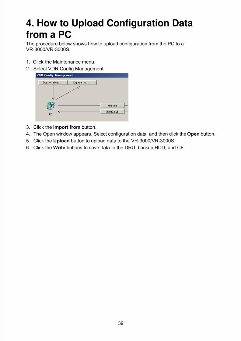
8102019 Ome44376d Vr3000 Mainte Cof26amp3bmol
httpslidepdfcomreaderfullome44376d-vr3000-mainte-cof26amp3bmol 4157
39
4 How to Upload Configuration Datafrom a PCThe procedure below shows how to upload configuration from the PC to aVR-3000VR-3000S
1 Click the Maintenance menu
2 Select VDR Config Management
3 Click the Import from button
4 The Open window appears Select configuration data and then click the Open button
5 Click the Upload button to upload data to the VR-3000VR-3000S
6 Click the Write buttons to save data to the DRU backup HDD and CF
8102019 Ome44376d Vr3000 Mainte Cof26amp3bmol
httpslidepdfcomreaderfullome44376d-vr3000-mainte-cof26amp3bmol 4257
40
5 Media ManagementThe media management feature deletes data from recording media initialization the
system etc There are two method LAN connection and Direct connection The Direct
connection takes longer time than the LAN connection Basically use the LAN connection
method
Note Initialization or creation of recording media is not available when Source Select onthe Live Player V4 is selected to Backup HDD
51 Initialization
This section shows how to delete data from the recording media Configuration data is
not deleted After performing the software configuration delete the data from the DRU
and HDD
Do the following to delete data from the DRU (LAN connection)
1 Set the PlaybackCPU switch in the DCU to the CPU position
2 Use an Ethernet cross cable to connect the PC to J14 (DATA) in the DCU (See page5)
3 Open the Tool menu
4 Select Media Management to open the VDR Media Management window
5 Check that IP address shown in the ldquoLAN Connect to IPrdquo in VDR Media Table Area isthe same as the IP address access point
6 Select ldquoLAN Connect to IPrdquo in the VDR Media Table column
8102019 Ome44376d Vr3000 Mainte Cof26amp3bmol
httpslidepdfcomreaderfullome44376d-vr3000-mainte-cof26amp3bmol 4357
41
7 Click the Analyze button A list of recording media connected to the VDR appears
Put a checkmark in the checkbox of the Select column for the DRU in the Name columnNote If there are several flash memories in the DRU all flash memories are shownCheck all flash memories shown
8 Select ldquoDRU Initializerdquo from the Operation dropdown list in the Operation area
10 Click the Run button
Do the following to delete data from the DRU (Direct connection)
1 Start Live Player V4 software
2 Open the Tool menu and select Source Select Select Live from the pull-downmenu
3 Click the Alarm tab and open Alarm History
4 Set the PlaybackCPU switch in the DCU to the Playback position
5 Wait approx 10 minutes and confirm that Alarm 174 occurs on Alarm History of LivePlayer V4
6 Connect an IEEEE1394 cable between J6 in the DCU and the PC
7 Open the Tool menu
8 Select Media Management to show the VDR Media Management window
9 Select Direct in the VDR Media Table column
10 Click the Analyze button A list of recording media connected to the VDR appears
11 Put a checkmark in the checkbox of the Select column for the DRU in the Namecolumn
Note If there are several flash memories in the DRU all flash memories are shownCheck all flash memories shown
12 Select ldquoDRU Initializerdquo from the Operation dropdown list in the Operation area
13 Enter password in the password column
14 Click the RUN button
8102019 Ome44376d Vr3000 Mainte Cof26amp3bmol
httpslidepdfcomreaderfullome44376d-vr3000-mainte-cof26amp3bmol 4457
42
Delete data from the Backup HDD as follows (LAN connection)
1 Set the PlaybackCPU switch in the DCU to the CPU position
2 Check that an Ethernet cross cable is connected between J14 in the DCU and the PC
3 Open the Tool menu
4 Select Media Management to open the VDR Media Management window
5 Check that IP address shown in the LAN Connect to IP in VDR Media Table Area is
the same as the IP address access point6 Select LAN Connect to IP in the VDR Media Table column
7 Click the Analyze button
8 A list of recording media connected to the VDR appears
9 Put a checkmark in the box of the Select column for the Backup HDD in the Namecolumn Select ldquoBackup HDD Initializerdquo from the Operation dropdown list in theOperation area
10 Click the Run button
Delete data from the Backup HDD as follows (Direct connection)
1 Start Live Player V4 software
2 Open the Tool menu and select Source Select Select Live from the pull-downmenu
3 Click the Alarm tab and open Alarm History
4 Set the PlaybackCPU switch in the DCU to the Playback position
5 Wait approx 10 minutes and confirm that Alarm 174 occurs on Alarm History of LivePlayer V4
6 Connect an IEEE1394 cable between J6 in the DCU and the PC
7 Open the Tool menu
8 Select Media Management to open the VDR Media Management window9 Select Direct in the VDR Media Table window
10 Click the Analyze button A list of recording media connected to the VDR appears
11 Put a checkmark in the check box of the Select column for the Backup HDD in theName column Select ldquoBackup HDD Initializerdquo from the Operation dropdown list in theOperation area
12 Enter password
13 Click the Run button
8102019 Ome44376d Vr3000 Mainte Cof26amp3bmol
httpslidepdfcomreaderfullome44376d-vr3000-mainte-cof26amp3bmol 4557
43
52 CreationThe Creation feature initializes recording media
Note1 This feature deletes ALL configuration data Backup all VDR configuration data
Note2 When you initialize medium that is a different format for the DRU or Backup HDDdelete all partitions with the disk management tool of Windows
Note3 When the Creation is failed try again If you can not initialize recording media tryunder condition as shown below
Do the Creation by the direct connection (When the Creation by the LAN
connection is failed)
Delete all partitions of the DRU or Backup HDD with the disk management tool of
Windows to do the Creation
If the Creation is still failed request service to repairreplace the DRU or Backup
HDD
Initialize the DRU as follows (LAN connection)
1 Set the PlaybackCPU switch in the DCU to the CPU position
2 Check that an Ethernet cross cable is connected between J14 in the DCU and the PC
3 Open the Tool menu
4 Select Media Management to open the VDR Media Management window
5 Check that IP address shown in the LAN Connect to IP in VDR Media Table Area isthe same as the IP address access point
6 Check ldquoLAN Connect to IPrdquo in the VDR Media Table column
7 Click the Analyze button A list of recording media connected to the VDR appears
8 Put a checkmark in the box of the Select column for the DRU in the Name column
Select ldquoDRU Creationrdquo from the Operation dropdown list in the Operation area
9 Click the Run button
Initialize the Backup HDD as follows (LAN connection)
1 To format the Backup HDD place a checkmark in the Select column of the listedrecord media in the Name column of the VDR Media Management dialogue box
2 From the Operation drop down list of the Operation area select ldquoBackup HDDCreation (Radar) or ldquoBackup HDD Creationrdquo
Two partition tools are available for the Backup HDD in the Media Management as
below
Backup HDD creation
This tool is used when the number of the SXGA video signal connected to the BackupHDD is the same as the DRU The same partition is created on both DRU and HDD
(1) When two SXGA video signals are recorded onto the HDD while 9-GB DRU isconnected
(2) When an SXGA video signal is recorded onto the HDD while 6-GB DRU isconnected
Backup HDD creation (radar)
This tool is used when two SXGA video signals are recorded onto the HDD with 6-GB
DRU connected The HDD has an area (radar) to record the second radar signal inaddition to the same partition as the DRU This tool cannot be used when 9-GB DRUis connected
3 Press the Run Button
8102019 Ome44376d Vr3000 Mainte Cof26amp3bmol
httpslidepdfcomreaderfullome44376d-vr3000-mainte-cof26amp3bmol 4657
44
Initialize the DRU as follows (Direct connection)
1 Start Live Player V4 software
2 Open the Tool menu and select Source Select Select Live from the pull-downmenu
3 Click the Alarm tab and open Alarm History
4 Set the PlaybackCPU switch in the DCU to the Playback position
5 Wait approx 10 minutes and confirm that Alarm 174 occurs on Alarm History of LivePlayer V4
6 Connect an IEEE1394 cable between J6 in the DCU and the PC
7 Open the Tool menu
8 Select Media Management to open the VDR Media Management window
9 Select Direct in the VDR Media Table window
10 Click the Analyze button A list of recording media connected to the VDR appears
11 Put a checkmark in the box of the Select column for the DRU and the desiredrecording media in the Name column In the Operation dropdown list of the Operationarea select ldquoDRU Creationrdquo
12 Enter password in the password column
13 Click the Run button
Initialize the Backup HDD as follows (Direct Connection)
1 To format the Backup HDD place a checkmark in the Select column of the listedrecord media in the Name column of the VDR Media Management dialogue box
2 From the Operation column of the Operation area select ldquoBackup HDD Creation(Radar) or ldquoBackup HDD Creationrdquo
Backup HDD creation
This tool is used when the number of the SXGA video signal connected to the BackupHDD is the same as the DRU The same partition is created on both DRU and HDD
(1) When two SXGA video signals are recorded onto the HDD while 9-GB DRU is
connected
(2) When an SXGA video signal is recorded onto the HDD while 6-GB DRU is
connected
Backup HDD creation (radar)
This tool is used when two SXGA video signals are recorded onto the HDD with 6-GBDRU connected The HDD has an area (radar) to record the second radar signal inaddition to the same partition as the DRU This tool cannot be used when 9-GB DRUis connected
3 Enter the password in the Password column
4 Press the Run Button
8102019 Ome44376d Vr3000 Mainte Cof26amp3bmol
httpslidepdfcomreaderfullome44376d-vr3000-mainte-cof26amp3bmol 4757
45
53 How to Enable Recording Area on the Backup HDD
This function enables writing over a recording area To prevent falsification of data all
recording areas must be saved otherwise this function is disabled To use this function push
the SAVE button Save the data before doing this procedure
Note Software version 135 or higher can enable writing over a recording area even if
all recording areas are not saved
Recording enable (LAN connection)
1 Set the PlaybackCPU switch in the DCU to the CPU position
2 Check that an Ethernet cross cable is connected between J14 in the DCU and the PC
3 Open the Tool menu
4 Select Media Management to open the VDR Media Management window
5 Check that IP address shown in the ldquoLAN Connect to IPrdquo in VDR Media Table Area isthe same as the IP address access point
6 Select ldquoLAN Connect to IPrdquo in the VDR Media Table column7 Click the Analyze button A list of recording media connected to the VDR appears
8 Put a checkmark in the box of the Select column for the Backup HDD in the Namecolumn
9 Select ldquoBackup HDD Recording Area Enablerdquo from the Operation dropdown list in theOperation area
10 Click the Run button
Recording enable (Direct connection)
1 Start Live Player V4 software
2 Open the Tool menu and select Source Select Select Live from the pull-down menu3 Click the Alarm tab and open Alarm History
4 Set the PlaybackCPU switch in the DCU to the Playback position
5 Wait approx 10 minutes and confirm that Alarm 174 occurs on Alarm History of LivePlayer V4
6 Connect an IEEE1394 cable between J6 in the DCU and the PC
7 Open the Tool menu
8 Select Media Management to open the VDR Media Management window
9 Select Direct in the VDR Media Table window
10 Click the Analyze button A list of recording media connected to the VDR appears11 Put a checkmark in the box of the Select column for the Backup HDD in the Name
column
12 Select ldquoBackup HDD Recording Area Enablerdquo from the Operation dropdown list in theOperation area
13 Enter password
14 Click the Run button
8102019 Ome44376d Vr3000 Mainte Cof26amp3bmol
httpslidepdfcomreaderfullome44376d-vr3000-mainte-cof26amp3bmol 4857
46
6 Other Functions
61 Software Management
The software download feature downloads VDR system software to the PC
To download software
1 Click the Maintenance menu
2 From the Software Management menu click Software Download to show theSoftware Download window
3 Enter the IP address 1000100 in the IP address box in the Update Server area
4 Click the Download Software button
5 The confirmation window appears click the OK button
The Software Backup Execute window shows the results of the download
Software is downloaded to C Program Files VDR Viewer Viewer Backup The software file
name is vdrtar
To Update Software
VDR system program version 16x can update the software with the procedure shownbelow
Note Do not update the file downloaded in procedures above
1 Click the Maintenance menu
2 From the Software Management menu click Software Upload to show the SoftwareUpload area
3 Click the Select button to show the Open window
4 Select update file (vdrtar) and click the Open button
8102019 Ome44376d Vr3000 Mainte Cof26amp3bmol
httpslidepdfcomreaderfullome44376d-vr3000-mainte-cof26amp3bmol 4957
47
5 Check the displayed Software information is correct
6 Enter the IP address 1000100 in the IP address box in the Update Server area
7 Enter password
8 Click the Update button
After the updating is completed the VDR is automatically restarted
Note Click the Restore button on the Software Update window to restore previoussoftware version This feature is available after updating the software
62 Password Management
The password can be changed for a serviceman to access the equipment Contact
FURUNO to get the default password to use during installation
Serviceman password
1 Click the Maintenance menu2 Select Change Serviceman Password from Password Management to show the
Change Serviceman Password window
3 Enter current password in the Old Password box
4 Enter the new password in the New Password box of the Change Password area
5 Enter new password again in the Confirm New Password box
6 Click the OK button
Audio password
The audio password set at the VDR Maintenance Viewer can be removed to enable
audio access without password1 Click the Maintenance menu
2 Select Change Audio Password from Password Management to show the Change Audio Password window
3 The confirmation window appears click the OK button
8102019 Ome44376d Vr3000 Mainte Cof26amp3bmol
httpslidepdfcomreaderfullome44376d-vr3000-mainte-cof26amp3bmol 5057
48
63 Record ComparisonThe integrity of the DRU and Backup HDD recordings can be compared This function isused by the RampD engineer for debugging
Follow the procedure as shown below
1 Click the Maintenance menu2 Select Record Comparison to show the Record Comparison window
The results are shown every 15 seconds in the Record Comparison window
8102019 Ome44376d Vr3000 Mainte Cof26amp3bmol
httpslidepdfcomreaderfullome44376d-vr3000-mainte-cof26amp3bmol 5157
49
64 Software History
This section shows you to save and configure software history (communications record)
How to save software history
Note When the error dialog appears while saving the software history restart the VDR
Maintenance Viewer
1 Click the Maintenance menu
2 Select Software History Collect
3 Click the Select button The Open dialog box appears
4 Select where to save the data then click the Open button
5 Select desired save condition then click the OK buttonNone No savingAt Once Save the software history manually Saving begins as soon as the OK button is clickedPeriodic For debugging Do not use otherwise The intervals are 30 sec 60 secand 120 secAlarm Detection For debugging Do not use otherwise Software history is savedwhen specified alarm is released Enter alarm number
How to configure software communications record
The RampD engineer uses this function for debugging Do not do this procedure unless
required Malfunction can result
1 Click the Maintenance menu
2 Select Software History Config
3 Do the followingProcess Select the type of communications record to save ALL saves allcommunications records
Detail Hide or show detailed information4 Click the Send button
8102019 Ome44376d Vr3000 Mainte Cof26amp3bmol
httpslidepdfcomreaderfullome44376d-vr3000-mainte-cof26amp3bmol 5257
50
65 Easy SetupThis feature sets equipment settings in batch and creates a data file of those settings
Default template The default template is created with the settings entered at installation
1 Click the Maintenance menu
2 Select Easy Setup to show the Template Selection window
3 Select Default Template
4 Click the Start button to show the Easy Setup window
5 Right click the channels (Radar Audio Digital Serial Analog) then select Edit toshow the Equipment Selection window
6 From the Equipment Directory window select equipment connected to the selectedchannel and then click the OK button
7 Repeat steps 5 and 6 to select equipment settings for each channel
8 Click the Save button in the Easy Setup window to show the Save window
9 Select where to save the file and enter file name
10 Click the Save button
8102019 Ome44376d Vr3000 Mainte Cof26amp3bmol
httpslidepdfcomreaderfullome44376d-vr3000-mainte-cof26amp3bmol 5357
51
Specific template Use a file already created
1 Click the Maintenance menu
2 Select Easy Setup to show the Template Selection window
3 Check Specified Template
4 Click the Select button and then select the file to edit
5 Click the Start button to show the Easy Setup window
6 Right click the channels (Radar Audio Digital Serial Analog) then select Edit toshow the Equipment Selection window
7 From the Equipment Directory window select equipment connected to the selectedchannel and then click the OK button
8 Repeat steps 6 and 7 to select equipment settings for each channel
9 Click the Save button in the Easy Setup window to show the Save window
10Select where to save the file and enter file name
11 Click the Save button
66 Equipment Management
This feature controls the import and export of equipment settings
Import data file
Import data files of equipment settings created in Easy Setup etc to the VDR
1 Click the Maintenance menu
2 Select Import from Equipment Management to show the Open window
3 Select the data file to import and click Open
Export data file
Export data files of equipment settings from the VDR to a PC
1 Click the Maintenance menu
2 Select Export from Equipment Management to show the Save window
3 Enter file name
4 Click the Save button
8102019 Ome44376d Vr3000 Mainte Cof26amp3bmol
httpslidepdfcomreaderfullome44376d-vr3000-mainte-cof26amp3bmol 5457
52
67 PC_RAP
This feature enables the same operation of the RAP (Remote Alarm Panel) from a PC
Select PC_RAP from the Tool menu to show the PC_RAP window
The buttons in the PC_RAP window function as shown below
SAVE Stop recording in the area where recording is currently being done
ACK Silence audio alarm
The PC_RAP display shows the following information with LEDs
RAP_LEDs Display the status of LEDs on the RAPSave The Save button blinks yellow when pushed When the 4 memory
areas have data recorded to them the Save button lights orange when
pushed
Normal Lights (green) where there are no unconfirmed or not restored
alarms
Error Flashes (red) for not confirmed alarm Lights (red) for unrestored
alarm
8102019 Ome44376d Vr3000 Mainte Cof26amp3bmol
httpslidepdfcomreaderfullome44376d-vr3000-mainte-cof26amp3bmol 5557
53
Backup HDD Information Display status of backup HDD
Selected Display current recording area and its status in green for
normal operation and in red for abnormal operation
Size Display capacity of backup HDD
Alarm area displays unconfirmed alarms
Time Display time alarm was generatedNumber Display number of alarm
Name Display name of alarm
Pending Alarm displays the unrestored alarms out of confirmed alarms only
Time Display time alarm was generated
Number Display number of alarm
Name Display name of alarm
8102019 Ome44376d Vr3000 Mainte Cof26amp3bmol
httpslidepdfcomreaderfullome44376d-vr3000-mainte-cof26amp3bmol 5657
54
68 Other
Status Monitor
The status monitor feature provides comprehensive data about the status of the VDR
From the menu bar click Toolgt Status Monitor to show the Status Monitor window
The buttons in the Status Monitor window work as shown below
Reload Settings for automatic refreshing of the status monitor
ON Turn automatic refresh OFF
OFF The Status Monitor is refreshed every five seconds
Save Available when Reload ON is selected The contents of the Status Monitor can be
saved to a text fileUpdate Update the Status Monitor display
Close Close the Status Monitor display
8102019 Ome44376d Vr3000 Mainte Cof26amp3bmol
httpslidepdfcomreaderfullome44376d-vr3000-mainte-cof26amp3bmol 5757
VDR Error List
This feature compiles all the errors shown on the RAP for easy reference
Access from MenugtToolgtVDR Error List
The VDR error list contains the following information
NO Display the number of the error
Title Display the name of the error
Detail Display details about the error
Exchange Check
This feature removes the alarms generated when replacing the DRU or backup HDD
Access MenugtToolgtExchange Check select either DRU or Backup HDD and click OK
Reboot
Reboot the VDR
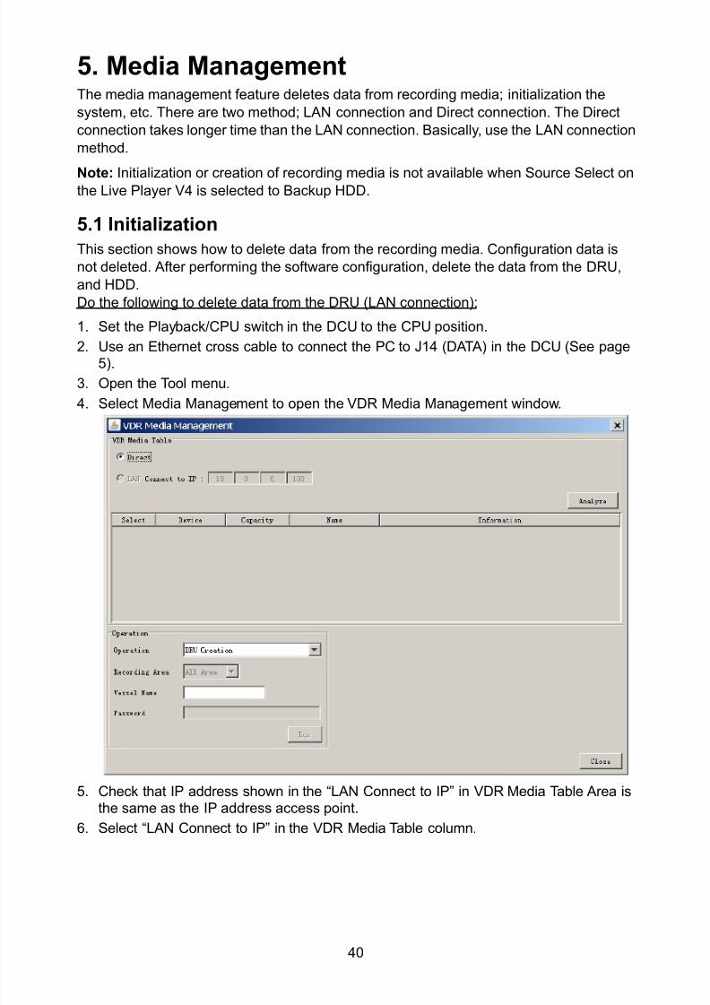
8102019 Ome44376d Vr3000 Mainte Cof26amp3bmol
httpslidepdfcomreaderfullome44376d-vr3000-mainte-cof26amp3bmol 4257
40
5 Media ManagementThe media management feature deletes data from recording media initialization the
system etc There are two method LAN connection and Direct connection The Direct
connection takes longer time than the LAN connection Basically use the LAN connection
method
Note Initialization or creation of recording media is not available when Source Select onthe Live Player V4 is selected to Backup HDD
51 Initialization
This section shows how to delete data from the recording media Configuration data is
not deleted After performing the software configuration delete the data from the DRU
and HDD
Do the following to delete data from the DRU (LAN connection)
1 Set the PlaybackCPU switch in the DCU to the CPU position
2 Use an Ethernet cross cable to connect the PC to J14 (DATA) in the DCU (See page5)
3 Open the Tool menu
4 Select Media Management to open the VDR Media Management window
5 Check that IP address shown in the ldquoLAN Connect to IPrdquo in VDR Media Table Area isthe same as the IP address access point
6 Select ldquoLAN Connect to IPrdquo in the VDR Media Table column
8102019 Ome44376d Vr3000 Mainte Cof26amp3bmol
httpslidepdfcomreaderfullome44376d-vr3000-mainte-cof26amp3bmol 4357
41
7 Click the Analyze button A list of recording media connected to the VDR appears
Put a checkmark in the checkbox of the Select column for the DRU in the Name columnNote If there are several flash memories in the DRU all flash memories are shownCheck all flash memories shown
8 Select ldquoDRU Initializerdquo from the Operation dropdown list in the Operation area
10 Click the Run button
Do the following to delete data from the DRU (Direct connection)
1 Start Live Player V4 software
2 Open the Tool menu and select Source Select Select Live from the pull-downmenu
3 Click the Alarm tab and open Alarm History
4 Set the PlaybackCPU switch in the DCU to the Playback position
5 Wait approx 10 minutes and confirm that Alarm 174 occurs on Alarm History of LivePlayer V4
6 Connect an IEEEE1394 cable between J6 in the DCU and the PC
7 Open the Tool menu
8 Select Media Management to show the VDR Media Management window
9 Select Direct in the VDR Media Table column
10 Click the Analyze button A list of recording media connected to the VDR appears
11 Put a checkmark in the checkbox of the Select column for the DRU in the Namecolumn
Note If there are several flash memories in the DRU all flash memories are shownCheck all flash memories shown
12 Select ldquoDRU Initializerdquo from the Operation dropdown list in the Operation area
13 Enter password in the password column
14 Click the RUN button
8102019 Ome44376d Vr3000 Mainte Cof26amp3bmol
httpslidepdfcomreaderfullome44376d-vr3000-mainte-cof26amp3bmol 4457
42
Delete data from the Backup HDD as follows (LAN connection)
1 Set the PlaybackCPU switch in the DCU to the CPU position
2 Check that an Ethernet cross cable is connected between J14 in the DCU and the PC
3 Open the Tool menu
4 Select Media Management to open the VDR Media Management window
5 Check that IP address shown in the LAN Connect to IP in VDR Media Table Area is
the same as the IP address access point6 Select LAN Connect to IP in the VDR Media Table column
7 Click the Analyze button
8 A list of recording media connected to the VDR appears
9 Put a checkmark in the box of the Select column for the Backup HDD in the Namecolumn Select ldquoBackup HDD Initializerdquo from the Operation dropdown list in theOperation area
10 Click the Run button
Delete data from the Backup HDD as follows (Direct connection)
1 Start Live Player V4 software
2 Open the Tool menu and select Source Select Select Live from the pull-downmenu
3 Click the Alarm tab and open Alarm History
4 Set the PlaybackCPU switch in the DCU to the Playback position
5 Wait approx 10 minutes and confirm that Alarm 174 occurs on Alarm History of LivePlayer V4
6 Connect an IEEE1394 cable between J6 in the DCU and the PC
7 Open the Tool menu
8 Select Media Management to open the VDR Media Management window9 Select Direct in the VDR Media Table window
10 Click the Analyze button A list of recording media connected to the VDR appears
11 Put a checkmark in the check box of the Select column for the Backup HDD in theName column Select ldquoBackup HDD Initializerdquo from the Operation dropdown list in theOperation area
12 Enter password
13 Click the Run button
8102019 Ome44376d Vr3000 Mainte Cof26amp3bmol
httpslidepdfcomreaderfullome44376d-vr3000-mainte-cof26amp3bmol 4557
43
52 CreationThe Creation feature initializes recording media
Note1 This feature deletes ALL configuration data Backup all VDR configuration data
Note2 When you initialize medium that is a different format for the DRU or Backup HDDdelete all partitions with the disk management tool of Windows
Note3 When the Creation is failed try again If you can not initialize recording media tryunder condition as shown below
Do the Creation by the direct connection (When the Creation by the LAN
connection is failed)
Delete all partitions of the DRU or Backup HDD with the disk management tool of
Windows to do the Creation
If the Creation is still failed request service to repairreplace the DRU or Backup
HDD
Initialize the DRU as follows (LAN connection)
1 Set the PlaybackCPU switch in the DCU to the CPU position
2 Check that an Ethernet cross cable is connected between J14 in the DCU and the PC
3 Open the Tool menu
4 Select Media Management to open the VDR Media Management window
5 Check that IP address shown in the LAN Connect to IP in VDR Media Table Area isthe same as the IP address access point
6 Check ldquoLAN Connect to IPrdquo in the VDR Media Table column
7 Click the Analyze button A list of recording media connected to the VDR appears
8 Put a checkmark in the box of the Select column for the DRU in the Name column
Select ldquoDRU Creationrdquo from the Operation dropdown list in the Operation area
9 Click the Run button
Initialize the Backup HDD as follows (LAN connection)
1 To format the Backup HDD place a checkmark in the Select column of the listedrecord media in the Name column of the VDR Media Management dialogue box
2 From the Operation drop down list of the Operation area select ldquoBackup HDDCreation (Radar) or ldquoBackup HDD Creationrdquo
Two partition tools are available for the Backup HDD in the Media Management as
below
Backup HDD creation
This tool is used when the number of the SXGA video signal connected to the BackupHDD is the same as the DRU The same partition is created on both DRU and HDD
(1) When two SXGA video signals are recorded onto the HDD while 9-GB DRU isconnected
(2) When an SXGA video signal is recorded onto the HDD while 6-GB DRU isconnected
Backup HDD creation (radar)
This tool is used when two SXGA video signals are recorded onto the HDD with 6-GB
DRU connected The HDD has an area (radar) to record the second radar signal inaddition to the same partition as the DRU This tool cannot be used when 9-GB DRUis connected
3 Press the Run Button
8102019 Ome44376d Vr3000 Mainte Cof26amp3bmol
httpslidepdfcomreaderfullome44376d-vr3000-mainte-cof26amp3bmol 4657
44
Initialize the DRU as follows (Direct connection)
1 Start Live Player V4 software
2 Open the Tool menu and select Source Select Select Live from the pull-downmenu
3 Click the Alarm tab and open Alarm History
4 Set the PlaybackCPU switch in the DCU to the Playback position
5 Wait approx 10 minutes and confirm that Alarm 174 occurs on Alarm History of LivePlayer V4
6 Connect an IEEE1394 cable between J6 in the DCU and the PC
7 Open the Tool menu
8 Select Media Management to open the VDR Media Management window
9 Select Direct in the VDR Media Table window
10 Click the Analyze button A list of recording media connected to the VDR appears
11 Put a checkmark in the box of the Select column for the DRU and the desiredrecording media in the Name column In the Operation dropdown list of the Operationarea select ldquoDRU Creationrdquo
12 Enter password in the password column
13 Click the Run button
Initialize the Backup HDD as follows (Direct Connection)
1 To format the Backup HDD place a checkmark in the Select column of the listedrecord media in the Name column of the VDR Media Management dialogue box
2 From the Operation column of the Operation area select ldquoBackup HDD Creation(Radar) or ldquoBackup HDD Creationrdquo
Backup HDD creation
This tool is used when the number of the SXGA video signal connected to the BackupHDD is the same as the DRU The same partition is created on both DRU and HDD
(1) When two SXGA video signals are recorded onto the HDD while 9-GB DRU is
connected
(2) When an SXGA video signal is recorded onto the HDD while 6-GB DRU is
connected
Backup HDD creation (radar)
This tool is used when two SXGA video signals are recorded onto the HDD with 6-GBDRU connected The HDD has an area (radar) to record the second radar signal inaddition to the same partition as the DRU This tool cannot be used when 9-GB DRUis connected
3 Enter the password in the Password column
4 Press the Run Button
8102019 Ome44376d Vr3000 Mainte Cof26amp3bmol
httpslidepdfcomreaderfullome44376d-vr3000-mainte-cof26amp3bmol 4757
45
53 How to Enable Recording Area on the Backup HDD
This function enables writing over a recording area To prevent falsification of data all
recording areas must be saved otherwise this function is disabled To use this function push
the SAVE button Save the data before doing this procedure
Note Software version 135 or higher can enable writing over a recording area even if
all recording areas are not saved
Recording enable (LAN connection)
1 Set the PlaybackCPU switch in the DCU to the CPU position
2 Check that an Ethernet cross cable is connected between J14 in the DCU and the PC
3 Open the Tool menu
4 Select Media Management to open the VDR Media Management window
5 Check that IP address shown in the ldquoLAN Connect to IPrdquo in VDR Media Table Area isthe same as the IP address access point
6 Select ldquoLAN Connect to IPrdquo in the VDR Media Table column7 Click the Analyze button A list of recording media connected to the VDR appears
8 Put a checkmark in the box of the Select column for the Backup HDD in the Namecolumn
9 Select ldquoBackup HDD Recording Area Enablerdquo from the Operation dropdown list in theOperation area
10 Click the Run button
Recording enable (Direct connection)
1 Start Live Player V4 software
2 Open the Tool menu and select Source Select Select Live from the pull-down menu3 Click the Alarm tab and open Alarm History
4 Set the PlaybackCPU switch in the DCU to the Playback position
5 Wait approx 10 minutes and confirm that Alarm 174 occurs on Alarm History of LivePlayer V4
6 Connect an IEEE1394 cable between J6 in the DCU and the PC
7 Open the Tool menu
8 Select Media Management to open the VDR Media Management window
9 Select Direct in the VDR Media Table window
10 Click the Analyze button A list of recording media connected to the VDR appears11 Put a checkmark in the box of the Select column for the Backup HDD in the Name
column
12 Select ldquoBackup HDD Recording Area Enablerdquo from the Operation dropdown list in theOperation area
13 Enter password
14 Click the Run button
8102019 Ome44376d Vr3000 Mainte Cof26amp3bmol
httpslidepdfcomreaderfullome44376d-vr3000-mainte-cof26amp3bmol 4857
46
6 Other Functions
61 Software Management
The software download feature downloads VDR system software to the PC
To download software
1 Click the Maintenance menu
2 From the Software Management menu click Software Download to show theSoftware Download window
3 Enter the IP address 1000100 in the IP address box in the Update Server area
4 Click the Download Software button
5 The confirmation window appears click the OK button
The Software Backup Execute window shows the results of the download
Software is downloaded to C Program Files VDR Viewer Viewer Backup The software file
name is vdrtar
To Update Software
VDR system program version 16x can update the software with the procedure shownbelow
Note Do not update the file downloaded in procedures above
1 Click the Maintenance menu
2 From the Software Management menu click Software Upload to show the SoftwareUpload area
3 Click the Select button to show the Open window
4 Select update file (vdrtar) and click the Open button
8102019 Ome44376d Vr3000 Mainte Cof26amp3bmol
httpslidepdfcomreaderfullome44376d-vr3000-mainte-cof26amp3bmol 4957
47
5 Check the displayed Software information is correct
6 Enter the IP address 1000100 in the IP address box in the Update Server area
7 Enter password
8 Click the Update button
After the updating is completed the VDR is automatically restarted
Note Click the Restore button on the Software Update window to restore previoussoftware version This feature is available after updating the software
62 Password Management
The password can be changed for a serviceman to access the equipment Contact
FURUNO to get the default password to use during installation
Serviceman password
1 Click the Maintenance menu2 Select Change Serviceman Password from Password Management to show the
Change Serviceman Password window
3 Enter current password in the Old Password box
4 Enter the new password in the New Password box of the Change Password area
5 Enter new password again in the Confirm New Password box
6 Click the OK button
Audio password
The audio password set at the VDR Maintenance Viewer can be removed to enable
audio access without password1 Click the Maintenance menu
2 Select Change Audio Password from Password Management to show the Change Audio Password window
3 The confirmation window appears click the OK button
8102019 Ome44376d Vr3000 Mainte Cof26amp3bmol
httpslidepdfcomreaderfullome44376d-vr3000-mainte-cof26amp3bmol 5057
48
63 Record ComparisonThe integrity of the DRU and Backup HDD recordings can be compared This function isused by the RampD engineer for debugging
Follow the procedure as shown below
1 Click the Maintenance menu2 Select Record Comparison to show the Record Comparison window
The results are shown every 15 seconds in the Record Comparison window
8102019 Ome44376d Vr3000 Mainte Cof26amp3bmol
httpslidepdfcomreaderfullome44376d-vr3000-mainte-cof26amp3bmol 5157
49
64 Software History
This section shows you to save and configure software history (communications record)
How to save software history
Note When the error dialog appears while saving the software history restart the VDR
Maintenance Viewer
1 Click the Maintenance menu
2 Select Software History Collect
3 Click the Select button The Open dialog box appears
4 Select where to save the data then click the Open button
5 Select desired save condition then click the OK buttonNone No savingAt Once Save the software history manually Saving begins as soon as the OK button is clickedPeriodic For debugging Do not use otherwise The intervals are 30 sec 60 secand 120 secAlarm Detection For debugging Do not use otherwise Software history is savedwhen specified alarm is released Enter alarm number
How to configure software communications record
The RampD engineer uses this function for debugging Do not do this procedure unless
required Malfunction can result
1 Click the Maintenance menu
2 Select Software History Config
3 Do the followingProcess Select the type of communications record to save ALL saves allcommunications records
Detail Hide or show detailed information4 Click the Send button
8102019 Ome44376d Vr3000 Mainte Cof26amp3bmol
httpslidepdfcomreaderfullome44376d-vr3000-mainte-cof26amp3bmol 5257
50
65 Easy SetupThis feature sets equipment settings in batch and creates a data file of those settings
Default template The default template is created with the settings entered at installation
1 Click the Maintenance menu
2 Select Easy Setup to show the Template Selection window
3 Select Default Template
4 Click the Start button to show the Easy Setup window
5 Right click the channels (Radar Audio Digital Serial Analog) then select Edit toshow the Equipment Selection window
6 From the Equipment Directory window select equipment connected to the selectedchannel and then click the OK button
7 Repeat steps 5 and 6 to select equipment settings for each channel
8 Click the Save button in the Easy Setup window to show the Save window
9 Select where to save the file and enter file name
10 Click the Save button
8102019 Ome44376d Vr3000 Mainte Cof26amp3bmol
httpslidepdfcomreaderfullome44376d-vr3000-mainte-cof26amp3bmol 5357
51
Specific template Use a file already created
1 Click the Maintenance menu
2 Select Easy Setup to show the Template Selection window
3 Check Specified Template
4 Click the Select button and then select the file to edit
5 Click the Start button to show the Easy Setup window
6 Right click the channels (Radar Audio Digital Serial Analog) then select Edit toshow the Equipment Selection window
7 From the Equipment Directory window select equipment connected to the selectedchannel and then click the OK button
8 Repeat steps 6 and 7 to select equipment settings for each channel
9 Click the Save button in the Easy Setup window to show the Save window
10Select where to save the file and enter file name
11 Click the Save button
66 Equipment Management
This feature controls the import and export of equipment settings
Import data file
Import data files of equipment settings created in Easy Setup etc to the VDR
1 Click the Maintenance menu
2 Select Import from Equipment Management to show the Open window
3 Select the data file to import and click Open
Export data file
Export data files of equipment settings from the VDR to a PC
1 Click the Maintenance menu
2 Select Export from Equipment Management to show the Save window
3 Enter file name
4 Click the Save button
8102019 Ome44376d Vr3000 Mainte Cof26amp3bmol
httpslidepdfcomreaderfullome44376d-vr3000-mainte-cof26amp3bmol 5457
52
67 PC_RAP
This feature enables the same operation of the RAP (Remote Alarm Panel) from a PC
Select PC_RAP from the Tool menu to show the PC_RAP window
The buttons in the PC_RAP window function as shown below
SAVE Stop recording in the area where recording is currently being done
ACK Silence audio alarm
The PC_RAP display shows the following information with LEDs
RAP_LEDs Display the status of LEDs on the RAPSave The Save button blinks yellow when pushed When the 4 memory
areas have data recorded to them the Save button lights orange when
pushed
Normal Lights (green) where there are no unconfirmed or not restored
alarms
Error Flashes (red) for not confirmed alarm Lights (red) for unrestored
alarm
8102019 Ome44376d Vr3000 Mainte Cof26amp3bmol
httpslidepdfcomreaderfullome44376d-vr3000-mainte-cof26amp3bmol 5557
53
Backup HDD Information Display status of backup HDD
Selected Display current recording area and its status in green for
normal operation and in red for abnormal operation
Size Display capacity of backup HDD
Alarm area displays unconfirmed alarms
Time Display time alarm was generatedNumber Display number of alarm
Name Display name of alarm
Pending Alarm displays the unrestored alarms out of confirmed alarms only
Time Display time alarm was generated
Number Display number of alarm
Name Display name of alarm
8102019 Ome44376d Vr3000 Mainte Cof26amp3bmol
httpslidepdfcomreaderfullome44376d-vr3000-mainte-cof26amp3bmol 5657
54
68 Other
Status Monitor
The status monitor feature provides comprehensive data about the status of the VDR
From the menu bar click Toolgt Status Monitor to show the Status Monitor window
The buttons in the Status Monitor window work as shown below
Reload Settings for automatic refreshing of the status monitor
ON Turn automatic refresh OFF
OFF The Status Monitor is refreshed every five seconds
Save Available when Reload ON is selected The contents of the Status Monitor can be
saved to a text fileUpdate Update the Status Monitor display
Close Close the Status Monitor display
8102019 Ome44376d Vr3000 Mainte Cof26amp3bmol
httpslidepdfcomreaderfullome44376d-vr3000-mainte-cof26amp3bmol 5757
VDR Error List
This feature compiles all the errors shown on the RAP for easy reference
Access from MenugtToolgtVDR Error List
The VDR error list contains the following information
NO Display the number of the error
Title Display the name of the error
Detail Display details about the error
Exchange Check
This feature removes the alarms generated when replacing the DRU or backup HDD
Access MenugtToolgtExchange Check select either DRU or Backup HDD and click OK
Reboot
Reboot the VDR
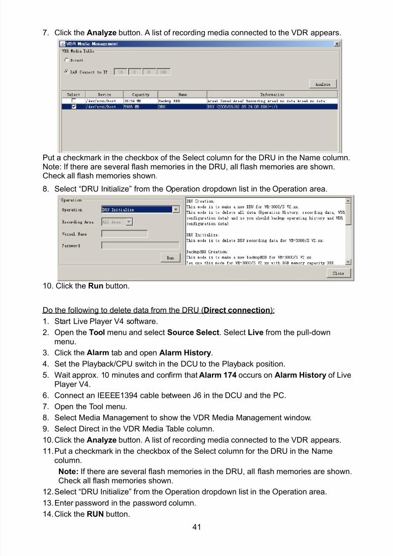
8102019 Ome44376d Vr3000 Mainte Cof26amp3bmol
httpslidepdfcomreaderfullome44376d-vr3000-mainte-cof26amp3bmol 4357
41
7 Click the Analyze button A list of recording media connected to the VDR appears
Put a checkmark in the checkbox of the Select column for the DRU in the Name columnNote If there are several flash memories in the DRU all flash memories are shownCheck all flash memories shown
8 Select ldquoDRU Initializerdquo from the Operation dropdown list in the Operation area
10 Click the Run button
Do the following to delete data from the DRU (Direct connection)
1 Start Live Player V4 software
2 Open the Tool menu and select Source Select Select Live from the pull-downmenu
3 Click the Alarm tab and open Alarm History
4 Set the PlaybackCPU switch in the DCU to the Playback position
5 Wait approx 10 minutes and confirm that Alarm 174 occurs on Alarm History of LivePlayer V4
6 Connect an IEEEE1394 cable between J6 in the DCU and the PC
7 Open the Tool menu
8 Select Media Management to show the VDR Media Management window
9 Select Direct in the VDR Media Table column
10 Click the Analyze button A list of recording media connected to the VDR appears
11 Put a checkmark in the checkbox of the Select column for the DRU in the Namecolumn
Note If there are several flash memories in the DRU all flash memories are shownCheck all flash memories shown
12 Select ldquoDRU Initializerdquo from the Operation dropdown list in the Operation area
13 Enter password in the password column
14 Click the RUN button
8102019 Ome44376d Vr3000 Mainte Cof26amp3bmol
httpslidepdfcomreaderfullome44376d-vr3000-mainte-cof26amp3bmol 4457
42
Delete data from the Backup HDD as follows (LAN connection)
1 Set the PlaybackCPU switch in the DCU to the CPU position
2 Check that an Ethernet cross cable is connected between J14 in the DCU and the PC
3 Open the Tool menu
4 Select Media Management to open the VDR Media Management window
5 Check that IP address shown in the LAN Connect to IP in VDR Media Table Area is
the same as the IP address access point6 Select LAN Connect to IP in the VDR Media Table column
7 Click the Analyze button
8 A list of recording media connected to the VDR appears
9 Put a checkmark in the box of the Select column for the Backup HDD in the Namecolumn Select ldquoBackup HDD Initializerdquo from the Operation dropdown list in theOperation area
10 Click the Run button
Delete data from the Backup HDD as follows (Direct connection)
1 Start Live Player V4 software
2 Open the Tool menu and select Source Select Select Live from the pull-downmenu
3 Click the Alarm tab and open Alarm History
4 Set the PlaybackCPU switch in the DCU to the Playback position
5 Wait approx 10 minutes and confirm that Alarm 174 occurs on Alarm History of LivePlayer V4
6 Connect an IEEE1394 cable between J6 in the DCU and the PC
7 Open the Tool menu
8 Select Media Management to open the VDR Media Management window9 Select Direct in the VDR Media Table window
10 Click the Analyze button A list of recording media connected to the VDR appears
11 Put a checkmark in the check box of the Select column for the Backup HDD in theName column Select ldquoBackup HDD Initializerdquo from the Operation dropdown list in theOperation area
12 Enter password
13 Click the Run button
8102019 Ome44376d Vr3000 Mainte Cof26amp3bmol
httpslidepdfcomreaderfullome44376d-vr3000-mainte-cof26amp3bmol 4557
43
52 CreationThe Creation feature initializes recording media
Note1 This feature deletes ALL configuration data Backup all VDR configuration data
Note2 When you initialize medium that is a different format for the DRU or Backup HDDdelete all partitions with the disk management tool of Windows
Note3 When the Creation is failed try again If you can not initialize recording media tryunder condition as shown below
Do the Creation by the direct connection (When the Creation by the LAN
connection is failed)
Delete all partitions of the DRU or Backup HDD with the disk management tool of
Windows to do the Creation
If the Creation is still failed request service to repairreplace the DRU or Backup
HDD
Initialize the DRU as follows (LAN connection)
1 Set the PlaybackCPU switch in the DCU to the CPU position
2 Check that an Ethernet cross cable is connected between J14 in the DCU and the PC
3 Open the Tool menu
4 Select Media Management to open the VDR Media Management window
5 Check that IP address shown in the LAN Connect to IP in VDR Media Table Area isthe same as the IP address access point
6 Check ldquoLAN Connect to IPrdquo in the VDR Media Table column
7 Click the Analyze button A list of recording media connected to the VDR appears
8 Put a checkmark in the box of the Select column for the DRU in the Name column
Select ldquoDRU Creationrdquo from the Operation dropdown list in the Operation area
9 Click the Run button
Initialize the Backup HDD as follows (LAN connection)
1 To format the Backup HDD place a checkmark in the Select column of the listedrecord media in the Name column of the VDR Media Management dialogue box
2 From the Operation drop down list of the Operation area select ldquoBackup HDDCreation (Radar) or ldquoBackup HDD Creationrdquo
Two partition tools are available for the Backup HDD in the Media Management as
below
Backup HDD creation
This tool is used when the number of the SXGA video signal connected to the BackupHDD is the same as the DRU The same partition is created on both DRU and HDD
(1) When two SXGA video signals are recorded onto the HDD while 9-GB DRU isconnected
(2) When an SXGA video signal is recorded onto the HDD while 6-GB DRU isconnected
Backup HDD creation (radar)
This tool is used when two SXGA video signals are recorded onto the HDD with 6-GB
DRU connected The HDD has an area (radar) to record the second radar signal inaddition to the same partition as the DRU This tool cannot be used when 9-GB DRUis connected
3 Press the Run Button
8102019 Ome44376d Vr3000 Mainte Cof26amp3bmol
httpslidepdfcomreaderfullome44376d-vr3000-mainte-cof26amp3bmol 4657
44
Initialize the DRU as follows (Direct connection)
1 Start Live Player V4 software
2 Open the Tool menu and select Source Select Select Live from the pull-downmenu
3 Click the Alarm tab and open Alarm History
4 Set the PlaybackCPU switch in the DCU to the Playback position
5 Wait approx 10 minutes and confirm that Alarm 174 occurs on Alarm History of LivePlayer V4
6 Connect an IEEE1394 cable between J6 in the DCU and the PC
7 Open the Tool menu
8 Select Media Management to open the VDR Media Management window
9 Select Direct in the VDR Media Table window
10 Click the Analyze button A list of recording media connected to the VDR appears
11 Put a checkmark in the box of the Select column for the DRU and the desiredrecording media in the Name column In the Operation dropdown list of the Operationarea select ldquoDRU Creationrdquo
12 Enter password in the password column
13 Click the Run button
Initialize the Backup HDD as follows (Direct Connection)
1 To format the Backup HDD place a checkmark in the Select column of the listedrecord media in the Name column of the VDR Media Management dialogue box
2 From the Operation column of the Operation area select ldquoBackup HDD Creation(Radar) or ldquoBackup HDD Creationrdquo
Backup HDD creation
This tool is used when the number of the SXGA video signal connected to the BackupHDD is the same as the DRU The same partition is created on both DRU and HDD
(1) When two SXGA video signals are recorded onto the HDD while 9-GB DRU is
connected
(2) When an SXGA video signal is recorded onto the HDD while 6-GB DRU is
connected
Backup HDD creation (radar)
This tool is used when two SXGA video signals are recorded onto the HDD with 6-GBDRU connected The HDD has an area (radar) to record the second radar signal inaddition to the same partition as the DRU This tool cannot be used when 9-GB DRUis connected
3 Enter the password in the Password column
4 Press the Run Button
8102019 Ome44376d Vr3000 Mainte Cof26amp3bmol
httpslidepdfcomreaderfullome44376d-vr3000-mainte-cof26amp3bmol 4757
45
53 How to Enable Recording Area on the Backup HDD
This function enables writing over a recording area To prevent falsification of data all
recording areas must be saved otherwise this function is disabled To use this function push
the SAVE button Save the data before doing this procedure
Note Software version 135 or higher can enable writing over a recording area even if
all recording areas are not saved
Recording enable (LAN connection)
1 Set the PlaybackCPU switch in the DCU to the CPU position
2 Check that an Ethernet cross cable is connected between J14 in the DCU and the PC
3 Open the Tool menu
4 Select Media Management to open the VDR Media Management window
5 Check that IP address shown in the ldquoLAN Connect to IPrdquo in VDR Media Table Area isthe same as the IP address access point
6 Select ldquoLAN Connect to IPrdquo in the VDR Media Table column7 Click the Analyze button A list of recording media connected to the VDR appears
8 Put a checkmark in the box of the Select column for the Backup HDD in the Namecolumn
9 Select ldquoBackup HDD Recording Area Enablerdquo from the Operation dropdown list in theOperation area
10 Click the Run button
Recording enable (Direct connection)
1 Start Live Player V4 software
2 Open the Tool menu and select Source Select Select Live from the pull-down menu3 Click the Alarm tab and open Alarm History
4 Set the PlaybackCPU switch in the DCU to the Playback position
5 Wait approx 10 minutes and confirm that Alarm 174 occurs on Alarm History of LivePlayer V4
6 Connect an IEEE1394 cable between J6 in the DCU and the PC
7 Open the Tool menu
8 Select Media Management to open the VDR Media Management window
9 Select Direct in the VDR Media Table window
10 Click the Analyze button A list of recording media connected to the VDR appears11 Put a checkmark in the box of the Select column for the Backup HDD in the Name
column
12 Select ldquoBackup HDD Recording Area Enablerdquo from the Operation dropdown list in theOperation area
13 Enter password
14 Click the Run button
8102019 Ome44376d Vr3000 Mainte Cof26amp3bmol
httpslidepdfcomreaderfullome44376d-vr3000-mainte-cof26amp3bmol 4857
46
6 Other Functions
61 Software Management
The software download feature downloads VDR system software to the PC
To download software
1 Click the Maintenance menu
2 From the Software Management menu click Software Download to show theSoftware Download window
3 Enter the IP address 1000100 in the IP address box in the Update Server area
4 Click the Download Software button
5 The confirmation window appears click the OK button
The Software Backup Execute window shows the results of the download
Software is downloaded to C Program Files VDR Viewer Viewer Backup The software file
name is vdrtar
To Update Software
VDR system program version 16x can update the software with the procedure shownbelow
Note Do not update the file downloaded in procedures above
1 Click the Maintenance menu
2 From the Software Management menu click Software Upload to show the SoftwareUpload area
3 Click the Select button to show the Open window
4 Select update file (vdrtar) and click the Open button
8102019 Ome44376d Vr3000 Mainte Cof26amp3bmol
httpslidepdfcomreaderfullome44376d-vr3000-mainte-cof26amp3bmol 4957
47
5 Check the displayed Software information is correct
6 Enter the IP address 1000100 in the IP address box in the Update Server area
7 Enter password
8 Click the Update button
After the updating is completed the VDR is automatically restarted
Note Click the Restore button on the Software Update window to restore previoussoftware version This feature is available after updating the software
62 Password Management
The password can be changed for a serviceman to access the equipment Contact
FURUNO to get the default password to use during installation
Serviceman password
1 Click the Maintenance menu2 Select Change Serviceman Password from Password Management to show the
Change Serviceman Password window
3 Enter current password in the Old Password box
4 Enter the new password in the New Password box of the Change Password area
5 Enter new password again in the Confirm New Password box
6 Click the OK button
Audio password
The audio password set at the VDR Maintenance Viewer can be removed to enable
audio access without password1 Click the Maintenance menu
2 Select Change Audio Password from Password Management to show the Change Audio Password window
3 The confirmation window appears click the OK button
8102019 Ome44376d Vr3000 Mainte Cof26amp3bmol
httpslidepdfcomreaderfullome44376d-vr3000-mainte-cof26amp3bmol 5057
48
63 Record ComparisonThe integrity of the DRU and Backup HDD recordings can be compared This function isused by the RampD engineer for debugging
Follow the procedure as shown below
1 Click the Maintenance menu2 Select Record Comparison to show the Record Comparison window
The results are shown every 15 seconds in the Record Comparison window
8102019 Ome44376d Vr3000 Mainte Cof26amp3bmol
httpslidepdfcomreaderfullome44376d-vr3000-mainte-cof26amp3bmol 5157
49
64 Software History
This section shows you to save and configure software history (communications record)
How to save software history
Note When the error dialog appears while saving the software history restart the VDR
Maintenance Viewer
1 Click the Maintenance menu
2 Select Software History Collect
3 Click the Select button The Open dialog box appears
4 Select where to save the data then click the Open button
5 Select desired save condition then click the OK buttonNone No savingAt Once Save the software history manually Saving begins as soon as the OK button is clickedPeriodic For debugging Do not use otherwise The intervals are 30 sec 60 secand 120 secAlarm Detection For debugging Do not use otherwise Software history is savedwhen specified alarm is released Enter alarm number
How to configure software communications record
The RampD engineer uses this function for debugging Do not do this procedure unless
required Malfunction can result
1 Click the Maintenance menu
2 Select Software History Config
3 Do the followingProcess Select the type of communications record to save ALL saves allcommunications records
Detail Hide or show detailed information4 Click the Send button
8102019 Ome44376d Vr3000 Mainte Cof26amp3bmol
httpslidepdfcomreaderfullome44376d-vr3000-mainte-cof26amp3bmol 5257
50
65 Easy SetupThis feature sets equipment settings in batch and creates a data file of those settings
Default template The default template is created with the settings entered at installation
1 Click the Maintenance menu
2 Select Easy Setup to show the Template Selection window
3 Select Default Template
4 Click the Start button to show the Easy Setup window
5 Right click the channels (Radar Audio Digital Serial Analog) then select Edit toshow the Equipment Selection window
6 From the Equipment Directory window select equipment connected to the selectedchannel and then click the OK button
7 Repeat steps 5 and 6 to select equipment settings for each channel
8 Click the Save button in the Easy Setup window to show the Save window
9 Select where to save the file and enter file name
10 Click the Save button
8102019 Ome44376d Vr3000 Mainte Cof26amp3bmol
httpslidepdfcomreaderfullome44376d-vr3000-mainte-cof26amp3bmol 5357
51
Specific template Use a file already created
1 Click the Maintenance menu
2 Select Easy Setup to show the Template Selection window
3 Check Specified Template
4 Click the Select button and then select the file to edit
5 Click the Start button to show the Easy Setup window
6 Right click the channels (Radar Audio Digital Serial Analog) then select Edit toshow the Equipment Selection window
7 From the Equipment Directory window select equipment connected to the selectedchannel and then click the OK button
8 Repeat steps 6 and 7 to select equipment settings for each channel
9 Click the Save button in the Easy Setup window to show the Save window
10Select where to save the file and enter file name
11 Click the Save button
66 Equipment Management
This feature controls the import and export of equipment settings
Import data file
Import data files of equipment settings created in Easy Setup etc to the VDR
1 Click the Maintenance menu
2 Select Import from Equipment Management to show the Open window
3 Select the data file to import and click Open
Export data file
Export data files of equipment settings from the VDR to a PC
1 Click the Maintenance menu
2 Select Export from Equipment Management to show the Save window
3 Enter file name
4 Click the Save button
8102019 Ome44376d Vr3000 Mainte Cof26amp3bmol
httpslidepdfcomreaderfullome44376d-vr3000-mainte-cof26amp3bmol 5457
52
67 PC_RAP
This feature enables the same operation of the RAP (Remote Alarm Panel) from a PC
Select PC_RAP from the Tool menu to show the PC_RAP window
The buttons in the PC_RAP window function as shown below
SAVE Stop recording in the area where recording is currently being done
ACK Silence audio alarm
The PC_RAP display shows the following information with LEDs
RAP_LEDs Display the status of LEDs on the RAPSave The Save button blinks yellow when pushed When the 4 memory
areas have data recorded to them the Save button lights orange when
pushed
Normal Lights (green) where there are no unconfirmed or not restored
alarms
Error Flashes (red) for not confirmed alarm Lights (red) for unrestored
alarm
8102019 Ome44376d Vr3000 Mainte Cof26amp3bmol
httpslidepdfcomreaderfullome44376d-vr3000-mainte-cof26amp3bmol 5557
53
Backup HDD Information Display status of backup HDD
Selected Display current recording area and its status in green for
normal operation and in red for abnormal operation
Size Display capacity of backup HDD
Alarm area displays unconfirmed alarms
Time Display time alarm was generatedNumber Display number of alarm
Name Display name of alarm
Pending Alarm displays the unrestored alarms out of confirmed alarms only
Time Display time alarm was generated
Number Display number of alarm
Name Display name of alarm
8102019 Ome44376d Vr3000 Mainte Cof26amp3bmol
httpslidepdfcomreaderfullome44376d-vr3000-mainte-cof26amp3bmol 5657
54
68 Other
Status Monitor
The status monitor feature provides comprehensive data about the status of the VDR
From the menu bar click Toolgt Status Monitor to show the Status Monitor window
The buttons in the Status Monitor window work as shown below
Reload Settings for automatic refreshing of the status monitor
ON Turn automatic refresh OFF
OFF The Status Monitor is refreshed every five seconds
Save Available when Reload ON is selected The contents of the Status Monitor can be
saved to a text fileUpdate Update the Status Monitor display
Close Close the Status Monitor display
8102019 Ome44376d Vr3000 Mainte Cof26amp3bmol
httpslidepdfcomreaderfullome44376d-vr3000-mainte-cof26amp3bmol 5757
VDR Error List
This feature compiles all the errors shown on the RAP for easy reference
Access from MenugtToolgtVDR Error List
The VDR error list contains the following information
NO Display the number of the error
Title Display the name of the error
Detail Display details about the error
Exchange Check
This feature removes the alarms generated when replacing the DRU or backup HDD
Access MenugtToolgtExchange Check select either DRU or Backup HDD and click OK
Reboot
Reboot the VDR
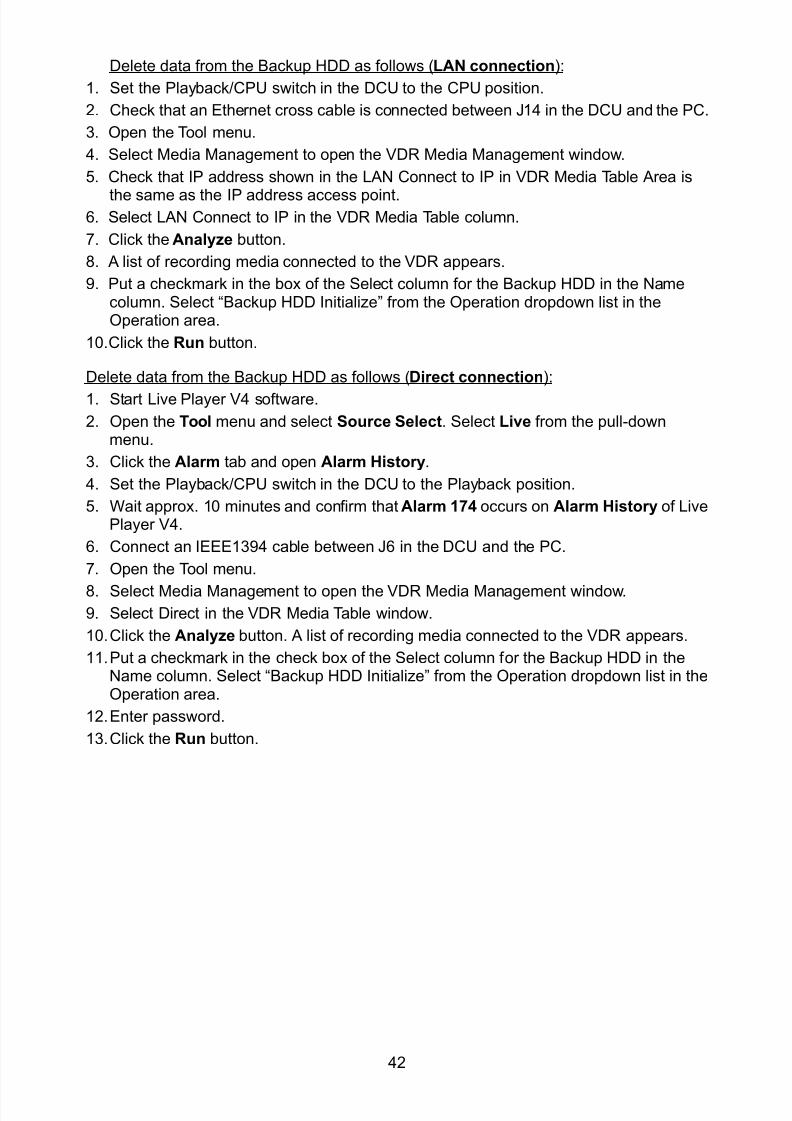
8102019 Ome44376d Vr3000 Mainte Cof26amp3bmol
httpslidepdfcomreaderfullome44376d-vr3000-mainte-cof26amp3bmol 4457
42
Delete data from the Backup HDD as follows (LAN connection)
1 Set the PlaybackCPU switch in the DCU to the CPU position
2 Check that an Ethernet cross cable is connected between J14 in the DCU and the PC
3 Open the Tool menu
4 Select Media Management to open the VDR Media Management window
5 Check that IP address shown in the LAN Connect to IP in VDR Media Table Area is
the same as the IP address access point6 Select LAN Connect to IP in the VDR Media Table column
7 Click the Analyze button
8 A list of recording media connected to the VDR appears
9 Put a checkmark in the box of the Select column for the Backup HDD in the Namecolumn Select ldquoBackup HDD Initializerdquo from the Operation dropdown list in theOperation area
10 Click the Run button
Delete data from the Backup HDD as follows (Direct connection)
1 Start Live Player V4 software
2 Open the Tool menu and select Source Select Select Live from the pull-downmenu
3 Click the Alarm tab and open Alarm History
4 Set the PlaybackCPU switch in the DCU to the Playback position
5 Wait approx 10 minutes and confirm that Alarm 174 occurs on Alarm History of LivePlayer V4
6 Connect an IEEE1394 cable between J6 in the DCU and the PC
7 Open the Tool menu
8 Select Media Management to open the VDR Media Management window9 Select Direct in the VDR Media Table window
10 Click the Analyze button A list of recording media connected to the VDR appears
11 Put a checkmark in the check box of the Select column for the Backup HDD in theName column Select ldquoBackup HDD Initializerdquo from the Operation dropdown list in theOperation area
12 Enter password
13 Click the Run button
8102019 Ome44376d Vr3000 Mainte Cof26amp3bmol
httpslidepdfcomreaderfullome44376d-vr3000-mainte-cof26amp3bmol 4557
43
52 CreationThe Creation feature initializes recording media
Note1 This feature deletes ALL configuration data Backup all VDR configuration data
Note2 When you initialize medium that is a different format for the DRU or Backup HDDdelete all partitions with the disk management tool of Windows
Note3 When the Creation is failed try again If you can not initialize recording media tryunder condition as shown below
Do the Creation by the direct connection (When the Creation by the LAN
connection is failed)
Delete all partitions of the DRU or Backup HDD with the disk management tool of
Windows to do the Creation
If the Creation is still failed request service to repairreplace the DRU or Backup
HDD
Initialize the DRU as follows (LAN connection)
1 Set the PlaybackCPU switch in the DCU to the CPU position
2 Check that an Ethernet cross cable is connected between J14 in the DCU and the PC
3 Open the Tool menu
4 Select Media Management to open the VDR Media Management window
5 Check that IP address shown in the LAN Connect to IP in VDR Media Table Area isthe same as the IP address access point
6 Check ldquoLAN Connect to IPrdquo in the VDR Media Table column
7 Click the Analyze button A list of recording media connected to the VDR appears
8 Put a checkmark in the box of the Select column for the DRU in the Name column
Select ldquoDRU Creationrdquo from the Operation dropdown list in the Operation area
9 Click the Run button
Initialize the Backup HDD as follows (LAN connection)
1 To format the Backup HDD place a checkmark in the Select column of the listedrecord media in the Name column of the VDR Media Management dialogue box
2 From the Operation drop down list of the Operation area select ldquoBackup HDDCreation (Radar) or ldquoBackup HDD Creationrdquo
Two partition tools are available for the Backup HDD in the Media Management as
below
Backup HDD creation
This tool is used when the number of the SXGA video signal connected to the BackupHDD is the same as the DRU The same partition is created on both DRU and HDD
(1) When two SXGA video signals are recorded onto the HDD while 9-GB DRU isconnected
(2) When an SXGA video signal is recorded onto the HDD while 6-GB DRU isconnected
Backup HDD creation (radar)
This tool is used when two SXGA video signals are recorded onto the HDD with 6-GB
DRU connected The HDD has an area (radar) to record the second radar signal inaddition to the same partition as the DRU This tool cannot be used when 9-GB DRUis connected
3 Press the Run Button
8102019 Ome44376d Vr3000 Mainte Cof26amp3bmol
httpslidepdfcomreaderfullome44376d-vr3000-mainte-cof26amp3bmol 4657
44
Initialize the DRU as follows (Direct connection)
1 Start Live Player V4 software
2 Open the Tool menu and select Source Select Select Live from the pull-downmenu
3 Click the Alarm tab and open Alarm History
4 Set the PlaybackCPU switch in the DCU to the Playback position
5 Wait approx 10 minutes and confirm that Alarm 174 occurs on Alarm History of LivePlayer V4
6 Connect an IEEE1394 cable between J6 in the DCU and the PC
7 Open the Tool menu
8 Select Media Management to open the VDR Media Management window
9 Select Direct in the VDR Media Table window
10 Click the Analyze button A list of recording media connected to the VDR appears
11 Put a checkmark in the box of the Select column for the DRU and the desiredrecording media in the Name column In the Operation dropdown list of the Operationarea select ldquoDRU Creationrdquo
12 Enter password in the password column
13 Click the Run button
Initialize the Backup HDD as follows (Direct Connection)
1 To format the Backup HDD place a checkmark in the Select column of the listedrecord media in the Name column of the VDR Media Management dialogue box
2 From the Operation column of the Operation area select ldquoBackup HDD Creation(Radar) or ldquoBackup HDD Creationrdquo
Backup HDD creation
This tool is used when the number of the SXGA video signal connected to the BackupHDD is the same as the DRU The same partition is created on both DRU and HDD
(1) When two SXGA video signals are recorded onto the HDD while 9-GB DRU is
connected
(2) When an SXGA video signal is recorded onto the HDD while 6-GB DRU is
connected
Backup HDD creation (radar)
This tool is used when two SXGA video signals are recorded onto the HDD with 6-GBDRU connected The HDD has an area (radar) to record the second radar signal inaddition to the same partition as the DRU This tool cannot be used when 9-GB DRUis connected
3 Enter the password in the Password column
4 Press the Run Button
8102019 Ome44376d Vr3000 Mainte Cof26amp3bmol
httpslidepdfcomreaderfullome44376d-vr3000-mainte-cof26amp3bmol 4757
45
53 How to Enable Recording Area on the Backup HDD
This function enables writing over a recording area To prevent falsification of data all
recording areas must be saved otherwise this function is disabled To use this function push
the SAVE button Save the data before doing this procedure
Note Software version 135 or higher can enable writing over a recording area even if
all recording areas are not saved
Recording enable (LAN connection)
1 Set the PlaybackCPU switch in the DCU to the CPU position
2 Check that an Ethernet cross cable is connected between J14 in the DCU and the PC
3 Open the Tool menu
4 Select Media Management to open the VDR Media Management window
5 Check that IP address shown in the ldquoLAN Connect to IPrdquo in VDR Media Table Area isthe same as the IP address access point
6 Select ldquoLAN Connect to IPrdquo in the VDR Media Table column7 Click the Analyze button A list of recording media connected to the VDR appears
8 Put a checkmark in the box of the Select column for the Backup HDD in the Namecolumn
9 Select ldquoBackup HDD Recording Area Enablerdquo from the Operation dropdown list in theOperation area
10 Click the Run button
Recording enable (Direct connection)
1 Start Live Player V4 software
2 Open the Tool menu and select Source Select Select Live from the pull-down menu3 Click the Alarm tab and open Alarm History
4 Set the PlaybackCPU switch in the DCU to the Playback position
5 Wait approx 10 minutes and confirm that Alarm 174 occurs on Alarm History of LivePlayer V4
6 Connect an IEEE1394 cable between J6 in the DCU and the PC
7 Open the Tool menu
8 Select Media Management to open the VDR Media Management window
9 Select Direct in the VDR Media Table window
10 Click the Analyze button A list of recording media connected to the VDR appears11 Put a checkmark in the box of the Select column for the Backup HDD in the Name
column
12 Select ldquoBackup HDD Recording Area Enablerdquo from the Operation dropdown list in theOperation area
13 Enter password
14 Click the Run button
8102019 Ome44376d Vr3000 Mainte Cof26amp3bmol
httpslidepdfcomreaderfullome44376d-vr3000-mainte-cof26amp3bmol 4857
46
6 Other Functions
61 Software Management
The software download feature downloads VDR system software to the PC
To download software
1 Click the Maintenance menu
2 From the Software Management menu click Software Download to show theSoftware Download window
3 Enter the IP address 1000100 in the IP address box in the Update Server area
4 Click the Download Software button
5 The confirmation window appears click the OK button
The Software Backup Execute window shows the results of the download
Software is downloaded to C Program Files VDR Viewer Viewer Backup The software file
name is vdrtar
To Update Software
VDR system program version 16x can update the software with the procedure shownbelow
Note Do not update the file downloaded in procedures above
1 Click the Maintenance menu
2 From the Software Management menu click Software Upload to show the SoftwareUpload area
3 Click the Select button to show the Open window
4 Select update file (vdrtar) and click the Open button
8102019 Ome44376d Vr3000 Mainte Cof26amp3bmol
httpslidepdfcomreaderfullome44376d-vr3000-mainte-cof26amp3bmol 4957
47
5 Check the displayed Software information is correct
6 Enter the IP address 1000100 in the IP address box in the Update Server area
7 Enter password
8 Click the Update button
After the updating is completed the VDR is automatically restarted
Note Click the Restore button on the Software Update window to restore previoussoftware version This feature is available after updating the software
62 Password Management
The password can be changed for a serviceman to access the equipment Contact
FURUNO to get the default password to use during installation
Serviceman password
1 Click the Maintenance menu2 Select Change Serviceman Password from Password Management to show the
Change Serviceman Password window
3 Enter current password in the Old Password box
4 Enter the new password in the New Password box of the Change Password area
5 Enter new password again in the Confirm New Password box
6 Click the OK button
Audio password
The audio password set at the VDR Maintenance Viewer can be removed to enable
audio access without password1 Click the Maintenance menu
2 Select Change Audio Password from Password Management to show the Change Audio Password window
3 The confirmation window appears click the OK button
8102019 Ome44376d Vr3000 Mainte Cof26amp3bmol
httpslidepdfcomreaderfullome44376d-vr3000-mainte-cof26amp3bmol 5057
48
63 Record ComparisonThe integrity of the DRU and Backup HDD recordings can be compared This function isused by the RampD engineer for debugging
Follow the procedure as shown below
1 Click the Maintenance menu2 Select Record Comparison to show the Record Comparison window
The results are shown every 15 seconds in the Record Comparison window
8102019 Ome44376d Vr3000 Mainte Cof26amp3bmol
httpslidepdfcomreaderfullome44376d-vr3000-mainte-cof26amp3bmol 5157
49
64 Software History
This section shows you to save and configure software history (communications record)
How to save software history
Note When the error dialog appears while saving the software history restart the VDR
Maintenance Viewer
1 Click the Maintenance menu
2 Select Software History Collect
3 Click the Select button The Open dialog box appears
4 Select where to save the data then click the Open button
5 Select desired save condition then click the OK buttonNone No savingAt Once Save the software history manually Saving begins as soon as the OK button is clickedPeriodic For debugging Do not use otherwise The intervals are 30 sec 60 secand 120 secAlarm Detection For debugging Do not use otherwise Software history is savedwhen specified alarm is released Enter alarm number
How to configure software communications record
The RampD engineer uses this function for debugging Do not do this procedure unless
required Malfunction can result
1 Click the Maintenance menu
2 Select Software History Config
3 Do the followingProcess Select the type of communications record to save ALL saves allcommunications records
Detail Hide or show detailed information4 Click the Send button
8102019 Ome44376d Vr3000 Mainte Cof26amp3bmol
httpslidepdfcomreaderfullome44376d-vr3000-mainte-cof26amp3bmol 5257
50
65 Easy SetupThis feature sets equipment settings in batch and creates a data file of those settings
Default template The default template is created with the settings entered at installation
1 Click the Maintenance menu
2 Select Easy Setup to show the Template Selection window
3 Select Default Template
4 Click the Start button to show the Easy Setup window
5 Right click the channels (Radar Audio Digital Serial Analog) then select Edit toshow the Equipment Selection window
6 From the Equipment Directory window select equipment connected to the selectedchannel and then click the OK button
7 Repeat steps 5 and 6 to select equipment settings for each channel
8 Click the Save button in the Easy Setup window to show the Save window
9 Select where to save the file and enter file name
10 Click the Save button
8102019 Ome44376d Vr3000 Mainte Cof26amp3bmol
httpslidepdfcomreaderfullome44376d-vr3000-mainte-cof26amp3bmol 5357
51
Specific template Use a file already created
1 Click the Maintenance menu
2 Select Easy Setup to show the Template Selection window
3 Check Specified Template
4 Click the Select button and then select the file to edit
5 Click the Start button to show the Easy Setup window
6 Right click the channels (Radar Audio Digital Serial Analog) then select Edit toshow the Equipment Selection window
7 From the Equipment Directory window select equipment connected to the selectedchannel and then click the OK button
8 Repeat steps 6 and 7 to select equipment settings for each channel
9 Click the Save button in the Easy Setup window to show the Save window
10Select where to save the file and enter file name
11 Click the Save button
66 Equipment Management
This feature controls the import and export of equipment settings
Import data file
Import data files of equipment settings created in Easy Setup etc to the VDR
1 Click the Maintenance menu
2 Select Import from Equipment Management to show the Open window
3 Select the data file to import and click Open
Export data file
Export data files of equipment settings from the VDR to a PC
1 Click the Maintenance menu
2 Select Export from Equipment Management to show the Save window
3 Enter file name
4 Click the Save button
8102019 Ome44376d Vr3000 Mainte Cof26amp3bmol
httpslidepdfcomreaderfullome44376d-vr3000-mainte-cof26amp3bmol 5457
52
67 PC_RAP
This feature enables the same operation of the RAP (Remote Alarm Panel) from a PC
Select PC_RAP from the Tool menu to show the PC_RAP window
The buttons in the PC_RAP window function as shown below
SAVE Stop recording in the area where recording is currently being done
ACK Silence audio alarm
The PC_RAP display shows the following information with LEDs
RAP_LEDs Display the status of LEDs on the RAPSave The Save button blinks yellow when pushed When the 4 memory
areas have data recorded to them the Save button lights orange when
pushed
Normal Lights (green) where there are no unconfirmed or not restored
alarms
Error Flashes (red) for not confirmed alarm Lights (red) for unrestored
alarm
8102019 Ome44376d Vr3000 Mainte Cof26amp3bmol
httpslidepdfcomreaderfullome44376d-vr3000-mainte-cof26amp3bmol 5557
53
Backup HDD Information Display status of backup HDD
Selected Display current recording area and its status in green for
normal operation and in red for abnormal operation
Size Display capacity of backup HDD
Alarm area displays unconfirmed alarms
Time Display time alarm was generatedNumber Display number of alarm
Name Display name of alarm
Pending Alarm displays the unrestored alarms out of confirmed alarms only
Time Display time alarm was generated
Number Display number of alarm
Name Display name of alarm
8102019 Ome44376d Vr3000 Mainte Cof26amp3bmol
httpslidepdfcomreaderfullome44376d-vr3000-mainte-cof26amp3bmol 5657
54
68 Other
Status Monitor
The status monitor feature provides comprehensive data about the status of the VDR
From the menu bar click Toolgt Status Monitor to show the Status Monitor window
The buttons in the Status Monitor window work as shown below
Reload Settings for automatic refreshing of the status monitor
ON Turn automatic refresh OFF
OFF The Status Monitor is refreshed every five seconds
Save Available when Reload ON is selected The contents of the Status Monitor can be
saved to a text fileUpdate Update the Status Monitor display
Close Close the Status Monitor display
8102019 Ome44376d Vr3000 Mainte Cof26amp3bmol
httpslidepdfcomreaderfullome44376d-vr3000-mainte-cof26amp3bmol 5757
VDR Error List
This feature compiles all the errors shown on the RAP for easy reference
Access from MenugtToolgtVDR Error List
The VDR error list contains the following information
NO Display the number of the error
Title Display the name of the error
Detail Display details about the error
Exchange Check
This feature removes the alarms generated when replacing the DRU or backup HDD
Access MenugtToolgtExchange Check select either DRU or Backup HDD and click OK
Reboot
Reboot the VDR
8102019 Ome44376d Vr3000 Mainte Cof26amp3bmol
httpslidepdfcomreaderfullome44376d-vr3000-mainte-cof26amp3bmol 4757
45
53 How to Enable Recording Area on the Backup HDD
This function enables writing over a recording area To prevent falsification of data all
recording areas must be saved otherwise this function is disabled To use this function push
the SAVE button Save the data before doing this procedure
Note Software version 135 or higher can enable writing over a recording area even if
all recording areas are not saved
Recording enable (LAN connection)
1 Set the PlaybackCPU switch in the DCU to the CPU position
2 Check that an Ethernet cross cable is connected between J14 in the DCU and the PC
3 Open the Tool menu
4 Select Media Management to open the VDR Media Management window
5 Check that IP address shown in the ldquoLAN Connect to IPrdquo in VDR Media Table Area isthe same as the IP address access point
6 Select ldquoLAN Connect to IPrdquo in the VDR Media Table column7 Click the Analyze button A list of recording media connected to the VDR appears
8 Put a checkmark in the box of the Select column for the Backup HDD in the Namecolumn
9 Select ldquoBackup HDD Recording Area Enablerdquo from the Operation dropdown list in theOperation area
10 Click the Run button
Recording enable (Direct connection)
1 Start Live Player V4 software
2 Open the Tool menu and select Source Select Select Live from the pull-down menu3 Click the Alarm tab and open Alarm History
4 Set the PlaybackCPU switch in the DCU to the Playback position
5 Wait approx 10 minutes and confirm that Alarm 174 occurs on Alarm History of LivePlayer V4
6 Connect an IEEE1394 cable between J6 in the DCU and the PC
7 Open the Tool menu
8 Select Media Management to open the VDR Media Management window
9 Select Direct in the VDR Media Table window
10 Click the Analyze button A list of recording media connected to the VDR appears11 Put a checkmark in the box of the Select column for the Backup HDD in the Name
column
12 Select ldquoBackup HDD Recording Area Enablerdquo from the Operation dropdown list in theOperation area
13 Enter password
14 Click the Run button
8102019 Ome44376d Vr3000 Mainte Cof26amp3bmol
httpslidepdfcomreaderfullome44376d-vr3000-mainte-cof26amp3bmol 4857
46
6 Other Functions
61 Software Management
The software download feature downloads VDR system software to the PC
To download software
1 Click the Maintenance menu
2 From the Software Management menu click Software Download to show theSoftware Download window
3 Enter the IP address 1000100 in the IP address box in the Update Server area
4 Click the Download Software button
5 The confirmation window appears click the OK button
The Software Backup Execute window shows the results of the download
Software is downloaded to C Program Files VDR Viewer Viewer Backup The software file
name is vdrtar
To Update Software
VDR system program version 16x can update the software with the procedure shownbelow
Note Do not update the file downloaded in procedures above
1 Click the Maintenance menu
2 From the Software Management menu click Software Upload to show the SoftwareUpload area
3 Click the Select button to show the Open window
4 Select update file (vdrtar) and click the Open button
8102019 Ome44376d Vr3000 Mainte Cof26amp3bmol
httpslidepdfcomreaderfullome44376d-vr3000-mainte-cof26amp3bmol 4957
47
5 Check the displayed Software information is correct
6 Enter the IP address 1000100 in the IP address box in the Update Server area
7 Enter password
8 Click the Update button
After the updating is completed the VDR is automatically restarted
Note Click the Restore button on the Software Update window to restore previoussoftware version This feature is available after updating the software
62 Password Management
The password can be changed for a serviceman to access the equipment Contact
FURUNO to get the default password to use during installation
Serviceman password
1 Click the Maintenance menu2 Select Change Serviceman Password from Password Management to show the
Change Serviceman Password window
3 Enter current password in the Old Password box
4 Enter the new password in the New Password box of the Change Password area
5 Enter new password again in the Confirm New Password box
6 Click the OK button
Audio password
The audio password set at the VDR Maintenance Viewer can be removed to enable
audio access without password1 Click the Maintenance menu
2 Select Change Audio Password from Password Management to show the Change Audio Password window
3 The confirmation window appears click the OK button
8102019 Ome44376d Vr3000 Mainte Cof26amp3bmol
httpslidepdfcomreaderfullome44376d-vr3000-mainte-cof26amp3bmol 5057
48
63 Record ComparisonThe integrity of the DRU and Backup HDD recordings can be compared This function isused by the RampD engineer for debugging
Follow the procedure as shown below
1 Click the Maintenance menu2 Select Record Comparison to show the Record Comparison window
The results are shown every 15 seconds in the Record Comparison window
8102019 Ome44376d Vr3000 Mainte Cof26amp3bmol
httpslidepdfcomreaderfullome44376d-vr3000-mainte-cof26amp3bmol 5157
49
64 Software History
This section shows you to save and configure software history (communications record)
How to save software history
Note When the error dialog appears while saving the software history restart the VDR
Maintenance Viewer
1 Click the Maintenance menu
2 Select Software History Collect
3 Click the Select button The Open dialog box appears
4 Select where to save the data then click the Open button
5 Select desired save condition then click the OK buttonNone No savingAt Once Save the software history manually Saving begins as soon as the OK button is clickedPeriodic For debugging Do not use otherwise The intervals are 30 sec 60 secand 120 secAlarm Detection For debugging Do not use otherwise Software history is savedwhen specified alarm is released Enter alarm number
How to configure software communications record
The RampD engineer uses this function for debugging Do not do this procedure unless
required Malfunction can result
1 Click the Maintenance menu
2 Select Software History Config
3 Do the followingProcess Select the type of communications record to save ALL saves allcommunications records
Detail Hide or show detailed information4 Click the Send button
8102019 Ome44376d Vr3000 Mainte Cof26amp3bmol
httpslidepdfcomreaderfullome44376d-vr3000-mainte-cof26amp3bmol 5257
50
65 Easy SetupThis feature sets equipment settings in batch and creates a data file of those settings
Default template The default template is created with the settings entered at installation
1 Click the Maintenance menu
2 Select Easy Setup to show the Template Selection window
3 Select Default Template
4 Click the Start button to show the Easy Setup window
5 Right click the channels (Radar Audio Digital Serial Analog) then select Edit toshow the Equipment Selection window
6 From the Equipment Directory window select equipment connected to the selectedchannel and then click the OK button
7 Repeat steps 5 and 6 to select equipment settings for each channel
8 Click the Save button in the Easy Setup window to show the Save window
9 Select where to save the file and enter file name
10 Click the Save button
8102019 Ome44376d Vr3000 Mainte Cof26amp3bmol
httpslidepdfcomreaderfullome44376d-vr3000-mainte-cof26amp3bmol 5357
51
Specific template Use a file already created
1 Click the Maintenance menu
2 Select Easy Setup to show the Template Selection window
3 Check Specified Template
4 Click the Select button and then select the file to edit
5 Click the Start button to show the Easy Setup window
6 Right click the channels (Radar Audio Digital Serial Analog) then select Edit toshow the Equipment Selection window
7 From the Equipment Directory window select equipment connected to the selectedchannel and then click the OK button
8 Repeat steps 6 and 7 to select equipment settings for each channel
9 Click the Save button in the Easy Setup window to show the Save window
10Select where to save the file and enter file name
11 Click the Save button
66 Equipment Management
This feature controls the import and export of equipment settings
Import data file
Import data files of equipment settings created in Easy Setup etc to the VDR
1 Click the Maintenance menu
2 Select Import from Equipment Management to show the Open window
3 Select the data file to import and click Open
Export data file
Export data files of equipment settings from the VDR to a PC
1 Click the Maintenance menu
2 Select Export from Equipment Management to show the Save window
3 Enter file name
4 Click the Save button
8102019 Ome44376d Vr3000 Mainte Cof26amp3bmol
httpslidepdfcomreaderfullome44376d-vr3000-mainte-cof26amp3bmol 5457
52
67 PC_RAP
This feature enables the same operation of the RAP (Remote Alarm Panel) from a PC
Select PC_RAP from the Tool menu to show the PC_RAP window
The buttons in the PC_RAP window function as shown below
SAVE Stop recording in the area where recording is currently being done
ACK Silence audio alarm
The PC_RAP display shows the following information with LEDs
RAP_LEDs Display the status of LEDs on the RAPSave The Save button blinks yellow when pushed When the 4 memory
areas have data recorded to them the Save button lights orange when
pushed
Normal Lights (green) where there are no unconfirmed or not restored
alarms
Error Flashes (red) for not confirmed alarm Lights (red) for unrestored
alarm
8102019 Ome44376d Vr3000 Mainte Cof26amp3bmol
httpslidepdfcomreaderfullome44376d-vr3000-mainte-cof26amp3bmol 5557
53
Backup HDD Information Display status of backup HDD
Selected Display current recording area and its status in green for
normal operation and in red for abnormal operation
Size Display capacity of backup HDD
Alarm area displays unconfirmed alarms
Time Display time alarm was generatedNumber Display number of alarm
Name Display name of alarm
Pending Alarm displays the unrestored alarms out of confirmed alarms only
Time Display time alarm was generated
Number Display number of alarm
Name Display name of alarm
8102019 Ome44376d Vr3000 Mainte Cof26amp3bmol
httpslidepdfcomreaderfullome44376d-vr3000-mainte-cof26amp3bmol 5657
54
68 Other
Status Monitor
The status monitor feature provides comprehensive data about the status of the VDR
From the menu bar click Toolgt Status Monitor to show the Status Monitor window
The buttons in the Status Monitor window work as shown below
Reload Settings for automatic refreshing of the status monitor
ON Turn automatic refresh OFF
OFF The Status Monitor is refreshed every five seconds
Save Available when Reload ON is selected The contents of the Status Monitor can be
saved to a text fileUpdate Update the Status Monitor display
Close Close the Status Monitor display
8102019 Ome44376d Vr3000 Mainte Cof26amp3bmol
httpslidepdfcomreaderfullome44376d-vr3000-mainte-cof26amp3bmol 5757
VDR Error List
This feature compiles all the errors shown on the RAP for easy reference
Access from MenugtToolgtVDR Error List
The VDR error list contains the following information
NO Display the number of the error
Title Display the name of the error
Detail Display details about the error
Exchange Check
This feature removes the alarms generated when replacing the DRU or backup HDD
Access MenugtToolgtExchange Check select either DRU or Backup HDD and click OK
Reboot
Reboot the VDR
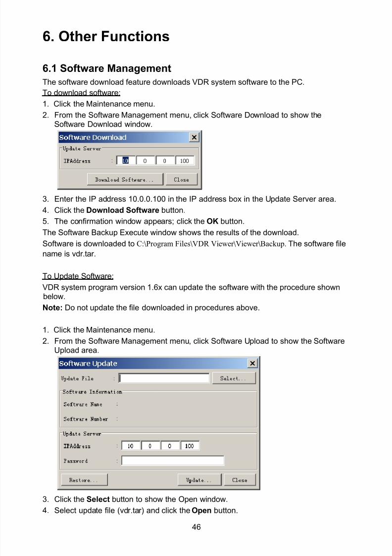
8102019 Ome44376d Vr3000 Mainte Cof26amp3bmol
httpslidepdfcomreaderfullome44376d-vr3000-mainte-cof26amp3bmol 4857
46
6 Other Functions
61 Software Management
The software download feature downloads VDR system software to the PC
To download software
1 Click the Maintenance menu
2 From the Software Management menu click Software Download to show theSoftware Download window
3 Enter the IP address 1000100 in the IP address box in the Update Server area
4 Click the Download Software button
5 The confirmation window appears click the OK button
The Software Backup Execute window shows the results of the download
Software is downloaded to C Program Files VDR Viewer Viewer Backup The software file
name is vdrtar
To Update Software
VDR system program version 16x can update the software with the procedure shownbelow
Note Do not update the file downloaded in procedures above
1 Click the Maintenance menu
2 From the Software Management menu click Software Upload to show the SoftwareUpload area
3 Click the Select button to show the Open window
4 Select update file (vdrtar) and click the Open button
8102019 Ome44376d Vr3000 Mainte Cof26amp3bmol
httpslidepdfcomreaderfullome44376d-vr3000-mainte-cof26amp3bmol 4957
47
5 Check the displayed Software information is correct
6 Enter the IP address 1000100 in the IP address box in the Update Server area
7 Enter password
8 Click the Update button
After the updating is completed the VDR is automatically restarted
Note Click the Restore button on the Software Update window to restore previoussoftware version This feature is available after updating the software
62 Password Management
The password can be changed for a serviceman to access the equipment Contact
FURUNO to get the default password to use during installation
Serviceman password
1 Click the Maintenance menu2 Select Change Serviceman Password from Password Management to show the
Change Serviceman Password window
3 Enter current password in the Old Password box
4 Enter the new password in the New Password box of the Change Password area
5 Enter new password again in the Confirm New Password box
6 Click the OK button
Audio password
The audio password set at the VDR Maintenance Viewer can be removed to enable
audio access without password1 Click the Maintenance menu
2 Select Change Audio Password from Password Management to show the Change Audio Password window
3 The confirmation window appears click the OK button
8102019 Ome44376d Vr3000 Mainte Cof26amp3bmol
httpslidepdfcomreaderfullome44376d-vr3000-mainte-cof26amp3bmol 5057
48
63 Record ComparisonThe integrity of the DRU and Backup HDD recordings can be compared This function isused by the RampD engineer for debugging
Follow the procedure as shown below
1 Click the Maintenance menu2 Select Record Comparison to show the Record Comparison window
The results are shown every 15 seconds in the Record Comparison window
8102019 Ome44376d Vr3000 Mainte Cof26amp3bmol
httpslidepdfcomreaderfullome44376d-vr3000-mainte-cof26amp3bmol 5157
49
64 Software History
This section shows you to save and configure software history (communications record)
How to save software history
Note When the error dialog appears while saving the software history restart the VDR
Maintenance Viewer
1 Click the Maintenance menu
2 Select Software History Collect
3 Click the Select button The Open dialog box appears
4 Select where to save the data then click the Open button
5 Select desired save condition then click the OK buttonNone No savingAt Once Save the software history manually Saving begins as soon as the OK button is clickedPeriodic For debugging Do not use otherwise The intervals are 30 sec 60 secand 120 secAlarm Detection For debugging Do not use otherwise Software history is savedwhen specified alarm is released Enter alarm number
How to configure software communications record
The RampD engineer uses this function for debugging Do not do this procedure unless
required Malfunction can result
1 Click the Maintenance menu
2 Select Software History Config
3 Do the followingProcess Select the type of communications record to save ALL saves allcommunications records
Detail Hide or show detailed information4 Click the Send button
8102019 Ome44376d Vr3000 Mainte Cof26amp3bmol
httpslidepdfcomreaderfullome44376d-vr3000-mainte-cof26amp3bmol 5257
50
65 Easy SetupThis feature sets equipment settings in batch and creates a data file of those settings
Default template The default template is created with the settings entered at installation
1 Click the Maintenance menu
2 Select Easy Setup to show the Template Selection window
3 Select Default Template
4 Click the Start button to show the Easy Setup window
5 Right click the channels (Radar Audio Digital Serial Analog) then select Edit toshow the Equipment Selection window
6 From the Equipment Directory window select equipment connected to the selectedchannel and then click the OK button
7 Repeat steps 5 and 6 to select equipment settings for each channel
8 Click the Save button in the Easy Setup window to show the Save window
9 Select where to save the file and enter file name
10 Click the Save button
8102019 Ome44376d Vr3000 Mainte Cof26amp3bmol
httpslidepdfcomreaderfullome44376d-vr3000-mainte-cof26amp3bmol 5357
51
Specific template Use a file already created
1 Click the Maintenance menu
2 Select Easy Setup to show the Template Selection window
3 Check Specified Template
4 Click the Select button and then select the file to edit
5 Click the Start button to show the Easy Setup window
6 Right click the channels (Radar Audio Digital Serial Analog) then select Edit toshow the Equipment Selection window
7 From the Equipment Directory window select equipment connected to the selectedchannel and then click the OK button
8 Repeat steps 6 and 7 to select equipment settings for each channel
9 Click the Save button in the Easy Setup window to show the Save window
10Select where to save the file and enter file name
11 Click the Save button
66 Equipment Management
This feature controls the import and export of equipment settings
Import data file
Import data files of equipment settings created in Easy Setup etc to the VDR
1 Click the Maintenance menu
2 Select Import from Equipment Management to show the Open window
3 Select the data file to import and click Open
Export data file
Export data files of equipment settings from the VDR to a PC
1 Click the Maintenance menu
2 Select Export from Equipment Management to show the Save window
3 Enter file name
4 Click the Save button
8102019 Ome44376d Vr3000 Mainte Cof26amp3bmol
httpslidepdfcomreaderfullome44376d-vr3000-mainte-cof26amp3bmol 5457
52
67 PC_RAP
This feature enables the same operation of the RAP (Remote Alarm Panel) from a PC
Select PC_RAP from the Tool menu to show the PC_RAP window
The buttons in the PC_RAP window function as shown below
SAVE Stop recording in the area where recording is currently being done
ACK Silence audio alarm
The PC_RAP display shows the following information with LEDs
RAP_LEDs Display the status of LEDs on the RAPSave The Save button blinks yellow when pushed When the 4 memory
areas have data recorded to them the Save button lights orange when
pushed
Normal Lights (green) where there are no unconfirmed or not restored
alarms
Error Flashes (red) for not confirmed alarm Lights (red) for unrestored
alarm
8102019 Ome44376d Vr3000 Mainte Cof26amp3bmol
httpslidepdfcomreaderfullome44376d-vr3000-mainte-cof26amp3bmol 5557
53
Backup HDD Information Display status of backup HDD
Selected Display current recording area and its status in green for
normal operation and in red for abnormal operation
Size Display capacity of backup HDD
Alarm area displays unconfirmed alarms
Time Display time alarm was generatedNumber Display number of alarm
Name Display name of alarm
Pending Alarm displays the unrestored alarms out of confirmed alarms only
Time Display time alarm was generated
Number Display number of alarm
Name Display name of alarm
8102019 Ome44376d Vr3000 Mainte Cof26amp3bmol
httpslidepdfcomreaderfullome44376d-vr3000-mainte-cof26amp3bmol 5657
54
68 Other
Status Monitor
The status monitor feature provides comprehensive data about the status of the VDR
From the menu bar click Toolgt Status Monitor to show the Status Monitor window
The buttons in the Status Monitor window work as shown below
Reload Settings for automatic refreshing of the status monitor
ON Turn automatic refresh OFF
OFF The Status Monitor is refreshed every five seconds
Save Available when Reload ON is selected The contents of the Status Monitor can be
saved to a text fileUpdate Update the Status Monitor display
Close Close the Status Monitor display
8102019 Ome44376d Vr3000 Mainte Cof26amp3bmol
httpslidepdfcomreaderfullome44376d-vr3000-mainte-cof26amp3bmol 5757
VDR Error List
This feature compiles all the errors shown on the RAP for easy reference
Access from MenugtToolgtVDR Error List
The VDR error list contains the following information
NO Display the number of the error
Title Display the name of the error
Detail Display details about the error
Exchange Check
This feature removes the alarms generated when replacing the DRU or backup HDD
Access MenugtToolgtExchange Check select either DRU or Backup HDD and click OK
Reboot
Reboot the VDR
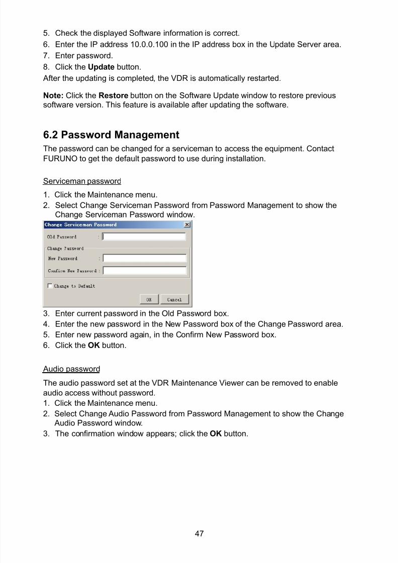
8102019 Ome44376d Vr3000 Mainte Cof26amp3bmol
httpslidepdfcomreaderfullome44376d-vr3000-mainte-cof26amp3bmol 4957
47
5 Check the displayed Software information is correct
6 Enter the IP address 1000100 in the IP address box in the Update Server area
7 Enter password
8 Click the Update button
After the updating is completed the VDR is automatically restarted
Note Click the Restore button on the Software Update window to restore previoussoftware version This feature is available after updating the software
62 Password Management
The password can be changed for a serviceman to access the equipment Contact
FURUNO to get the default password to use during installation
Serviceman password
1 Click the Maintenance menu2 Select Change Serviceman Password from Password Management to show the
Change Serviceman Password window
3 Enter current password in the Old Password box
4 Enter the new password in the New Password box of the Change Password area
5 Enter new password again in the Confirm New Password box
6 Click the OK button
Audio password
The audio password set at the VDR Maintenance Viewer can be removed to enable
audio access without password1 Click the Maintenance menu
2 Select Change Audio Password from Password Management to show the Change Audio Password window
3 The confirmation window appears click the OK button
8102019 Ome44376d Vr3000 Mainte Cof26amp3bmol
httpslidepdfcomreaderfullome44376d-vr3000-mainte-cof26amp3bmol 5057
48
63 Record ComparisonThe integrity of the DRU and Backup HDD recordings can be compared This function isused by the RampD engineer for debugging
Follow the procedure as shown below
1 Click the Maintenance menu2 Select Record Comparison to show the Record Comparison window
The results are shown every 15 seconds in the Record Comparison window
8102019 Ome44376d Vr3000 Mainte Cof26amp3bmol
httpslidepdfcomreaderfullome44376d-vr3000-mainte-cof26amp3bmol 5157
49
64 Software History
This section shows you to save and configure software history (communications record)
How to save software history
Note When the error dialog appears while saving the software history restart the VDR
Maintenance Viewer
1 Click the Maintenance menu
2 Select Software History Collect
3 Click the Select button The Open dialog box appears
4 Select where to save the data then click the Open button
5 Select desired save condition then click the OK buttonNone No savingAt Once Save the software history manually Saving begins as soon as the OK button is clickedPeriodic For debugging Do not use otherwise The intervals are 30 sec 60 secand 120 secAlarm Detection For debugging Do not use otherwise Software history is savedwhen specified alarm is released Enter alarm number
How to configure software communications record
The RampD engineer uses this function for debugging Do not do this procedure unless
required Malfunction can result
1 Click the Maintenance menu
2 Select Software History Config
3 Do the followingProcess Select the type of communications record to save ALL saves allcommunications records
Detail Hide or show detailed information4 Click the Send button
8102019 Ome44376d Vr3000 Mainte Cof26amp3bmol
httpslidepdfcomreaderfullome44376d-vr3000-mainte-cof26amp3bmol 5257
50
65 Easy SetupThis feature sets equipment settings in batch and creates a data file of those settings
Default template The default template is created with the settings entered at installation
1 Click the Maintenance menu
2 Select Easy Setup to show the Template Selection window
3 Select Default Template
4 Click the Start button to show the Easy Setup window
5 Right click the channels (Radar Audio Digital Serial Analog) then select Edit toshow the Equipment Selection window
6 From the Equipment Directory window select equipment connected to the selectedchannel and then click the OK button
7 Repeat steps 5 and 6 to select equipment settings for each channel
8 Click the Save button in the Easy Setup window to show the Save window
9 Select where to save the file and enter file name
10 Click the Save button
8102019 Ome44376d Vr3000 Mainte Cof26amp3bmol
httpslidepdfcomreaderfullome44376d-vr3000-mainte-cof26amp3bmol 5357
51
Specific template Use a file already created
1 Click the Maintenance menu
2 Select Easy Setup to show the Template Selection window
3 Check Specified Template
4 Click the Select button and then select the file to edit
5 Click the Start button to show the Easy Setup window
6 Right click the channels (Radar Audio Digital Serial Analog) then select Edit toshow the Equipment Selection window
7 From the Equipment Directory window select equipment connected to the selectedchannel and then click the OK button
8 Repeat steps 6 and 7 to select equipment settings for each channel
9 Click the Save button in the Easy Setup window to show the Save window
10Select where to save the file and enter file name
11 Click the Save button
66 Equipment Management
This feature controls the import and export of equipment settings
Import data file
Import data files of equipment settings created in Easy Setup etc to the VDR
1 Click the Maintenance menu
2 Select Import from Equipment Management to show the Open window
3 Select the data file to import and click Open
Export data file
Export data files of equipment settings from the VDR to a PC
1 Click the Maintenance menu
2 Select Export from Equipment Management to show the Save window
3 Enter file name
4 Click the Save button
8102019 Ome44376d Vr3000 Mainte Cof26amp3bmol
httpslidepdfcomreaderfullome44376d-vr3000-mainte-cof26amp3bmol 5457
52
67 PC_RAP
This feature enables the same operation of the RAP (Remote Alarm Panel) from a PC
Select PC_RAP from the Tool menu to show the PC_RAP window
The buttons in the PC_RAP window function as shown below
SAVE Stop recording in the area where recording is currently being done
ACK Silence audio alarm
The PC_RAP display shows the following information with LEDs
RAP_LEDs Display the status of LEDs on the RAPSave The Save button blinks yellow when pushed When the 4 memory
areas have data recorded to them the Save button lights orange when
pushed
Normal Lights (green) where there are no unconfirmed or not restored
alarms
Error Flashes (red) for not confirmed alarm Lights (red) for unrestored
alarm
8102019 Ome44376d Vr3000 Mainte Cof26amp3bmol
httpslidepdfcomreaderfullome44376d-vr3000-mainte-cof26amp3bmol 5557
53
Backup HDD Information Display status of backup HDD
Selected Display current recording area and its status in green for
normal operation and in red for abnormal operation
Size Display capacity of backup HDD
Alarm area displays unconfirmed alarms
Time Display time alarm was generatedNumber Display number of alarm
Name Display name of alarm
Pending Alarm displays the unrestored alarms out of confirmed alarms only
Time Display time alarm was generated
Number Display number of alarm
Name Display name of alarm
8102019 Ome44376d Vr3000 Mainte Cof26amp3bmol
httpslidepdfcomreaderfullome44376d-vr3000-mainte-cof26amp3bmol 5657
54
68 Other
Status Monitor
The status monitor feature provides comprehensive data about the status of the VDR
From the menu bar click Toolgt Status Monitor to show the Status Monitor window
The buttons in the Status Monitor window work as shown below
Reload Settings for automatic refreshing of the status monitor
ON Turn automatic refresh OFF
OFF The Status Monitor is refreshed every five seconds
Save Available when Reload ON is selected The contents of the Status Monitor can be
saved to a text fileUpdate Update the Status Monitor display
Close Close the Status Monitor display
8102019 Ome44376d Vr3000 Mainte Cof26amp3bmol
httpslidepdfcomreaderfullome44376d-vr3000-mainte-cof26amp3bmol 5757
VDR Error List
This feature compiles all the errors shown on the RAP for easy reference
Access from MenugtToolgtVDR Error List
The VDR error list contains the following information
NO Display the number of the error
Title Display the name of the error
Detail Display details about the error
Exchange Check
This feature removes the alarms generated when replacing the DRU or backup HDD
Access MenugtToolgtExchange Check select either DRU or Backup HDD and click OK
Reboot
Reboot the VDR
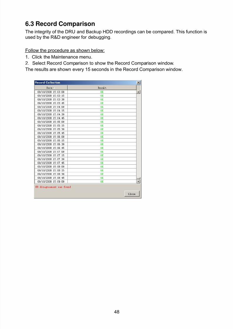
8102019 Ome44376d Vr3000 Mainte Cof26amp3bmol
httpslidepdfcomreaderfullome44376d-vr3000-mainte-cof26amp3bmol 5057
48
63 Record ComparisonThe integrity of the DRU and Backup HDD recordings can be compared This function isused by the RampD engineer for debugging
Follow the procedure as shown below
1 Click the Maintenance menu2 Select Record Comparison to show the Record Comparison window
The results are shown every 15 seconds in the Record Comparison window
8102019 Ome44376d Vr3000 Mainte Cof26amp3bmol
httpslidepdfcomreaderfullome44376d-vr3000-mainte-cof26amp3bmol 5157
49
64 Software History
This section shows you to save and configure software history (communications record)
How to save software history
Note When the error dialog appears while saving the software history restart the VDR
Maintenance Viewer
1 Click the Maintenance menu
2 Select Software History Collect
3 Click the Select button The Open dialog box appears
4 Select where to save the data then click the Open button
5 Select desired save condition then click the OK buttonNone No savingAt Once Save the software history manually Saving begins as soon as the OK button is clickedPeriodic For debugging Do not use otherwise The intervals are 30 sec 60 secand 120 secAlarm Detection For debugging Do not use otherwise Software history is savedwhen specified alarm is released Enter alarm number
How to configure software communications record
The RampD engineer uses this function for debugging Do not do this procedure unless
required Malfunction can result
1 Click the Maintenance menu
2 Select Software History Config
3 Do the followingProcess Select the type of communications record to save ALL saves allcommunications records
Detail Hide or show detailed information4 Click the Send button
8102019 Ome44376d Vr3000 Mainte Cof26amp3bmol
httpslidepdfcomreaderfullome44376d-vr3000-mainte-cof26amp3bmol 5257
50
65 Easy SetupThis feature sets equipment settings in batch and creates a data file of those settings
Default template The default template is created with the settings entered at installation
1 Click the Maintenance menu
2 Select Easy Setup to show the Template Selection window
3 Select Default Template
4 Click the Start button to show the Easy Setup window
5 Right click the channels (Radar Audio Digital Serial Analog) then select Edit toshow the Equipment Selection window
6 From the Equipment Directory window select equipment connected to the selectedchannel and then click the OK button
7 Repeat steps 5 and 6 to select equipment settings for each channel
8 Click the Save button in the Easy Setup window to show the Save window
9 Select where to save the file and enter file name
10 Click the Save button
8102019 Ome44376d Vr3000 Mainte Cof26amp3bmol
httpslidepdfcomreaderfullome44376d-vr3000-mainte-cof26amp3bmol 5357
51
Specific template Use a file already created
1 Click the Maintenance menu
2 Select Easy Setup to show the Template Selection window
3 Check Specified Template
4 Click the Select button and then select the file to edit
5 Click the Start button to show the Easy Setup window
6 Right click the channels (Radar Audio Digital Serial Analog) then select Edit toshow the Equipment Selection window
7 From the Equipment Directory window select equipment connected to the selectedchannel and then click the OK button
8 Repeat steps 6 and 7 to select equipment settings for each channel
9 Click the Save button in the Easy Setup window to show the Save window
10Select where to save the file and enter file name
11 Click the Save button
66 Equipment Management
This feature controls the import and export of equipment settings
Import data file
Import data files of equipment settings created in Easy Setup etc to the VDR
1 Click the Maintenance menu
2 Select Import from Equipment Management to show the Open window
3 Select the data file to import and click Open
Export data file
Export data files of equipment settings from the VDR to a PC
1 Click the Maintenance menu
2 Select Export from Equipment Management to show the Save window
3 Enter file name
4 Click the Save button
8102019 Ome44376d Vr3000 Mainte Cof26amp3bmol
httpslidepdfcomreaderfullome44376d-vr3000-mainte-cof26amp3bmol 5457
52
67 PC_RAP
This feature enables the same operation of the RAP (Remote Alarm Panel) from a PC
Select PC_RAP from the Tool menu to show the PC_RAP window
The buttons in the PC_RAP window function as shown below
SAVE Stop recording in the area where recording is currently being done
ACK Silence audio alarm
The PC_RAP display shows the following information with LEDs
RAP_LEDs Display the status of LEDs on the RAPSave The Save button blinks yellow when pushed When the 4 memory
areas have data recorded to them the Save button lights orange when
pushed
Normal Lights (green) where there are no unconfirmed or not restored
alarms
Error Flashes (red) for not confirmed alarm Lights (red) for unrestored
alarm
8102019 Ome44376d Vr3000 Mainte Cof26amp3bmol
httpslidepdfcomreaderfullome44376d-vr3000-mainte-cof26amp3bmol 5557
53
Backup HDD Information Display status of backup HDD
Selected Display current recording area and its status in green for
normal operation and in red for abnormal operation
Size Display capacity of backup HDD
Alarm area displays unconfirmed alarms
Time Display time alarm was generatedNumber Display number of alarm
Name Display name of alarm
Pending Alarm displays the unrestored alarms out of confirmed alarms only
Time Display time alarm was generated
Number Display number of alarm
Name Display name of alarm
8102019 Ome44376d Vr3000 Mainte Cof26amp3bmol
httpslidepdfcomreaderfullome44376d-vr3000-mainte-cof26amp3bmol 5657
54
68 Other
Status Monitor
The status monitor feature provides comprehensive data about the status of the VDR
From the menu bar click Toolgt Status Monitor to show the Status Monitor window
The buttons in the Status Monitor window work as shown below
Reload Settings for automatic refreshing of the status monitor
ON Turn automatic refresh OFF
OFF The Status Monitor is refreshed every five seconds
Save Available when Reload ON is selected The contents of the Status Monitor can be
saved to a text fileUpdate Update the Status Monitor display
Close Close the Status Monitor display
8102019 Ome44376d Vr3000 Mainte Cof26amp3bmol
httpslidepdfcomreaderfullome44376d-vr3000-mainte-cof26amp3bmol 5757
VDR Error List
This feature compiles all the errors shown on the RAP for easy reference
Access from MenugtToolgtVDR Error List
The VDR error list contains the following information
NO Display the number of the error
Title Display the name of the error
Detail Display details about the error
Exchange Check
This feature removes the alarms generated when replacing the DRU or backup HDD
Access MenugtToolgtExchange Check select either DRU or Backup HDD and click OK
Reboot
Reboot the VDR
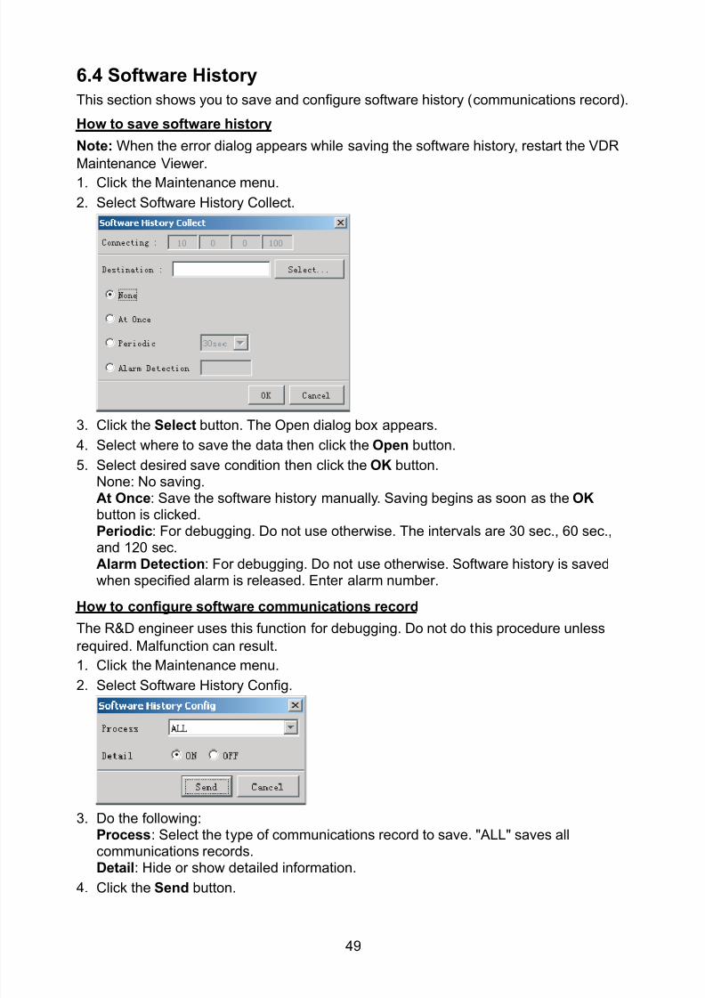
8102019 Ome44376d Vr3000 Mainte Cof26amp3bmol
httpslidepdfcomreaderfullome44376d-vr3000-mainte-cof26amp3bmol 5257
50
65 Easy SetupThis feature sets equipment settings in batch and creates a data file of those settings
Default template The default template is created with the settings entered at installation
1 Click the Maintenance menu
2 Select Easy Setup to show the Template Selection window
3 Select Default Template
4 Click the Start button to show the Easy Setup window
5 Right click the channels (Radar Audio Digital Serial Analog) then select Edit toshow the Equipment Selection window
6 From the Equipment Directory window select equipment connected to the selectedchannel and then click the OK button
7 Repeat steps 5 and 6 to select equipment settings for each channel
8 Click the Save button in the Easy Setup window to show the Save window
9 Select where to save the file and enter file name
10 Click the Save button
8102019 Ome44376d Vr3000 Mainte Cof26amp3bmol
httpslidepdfcomreaderfullome44376d-vr3000-mainte-cof26amp3bmol 5357
51
Specific template Use a file already created
1 Click the Maintenance menu
2 Select Easy Setup to show the Template Selection window
3 Check Specified Template
4 Click the Select button and then select the file to edit
5 Click the Start button to show the Easy Setup window
6 Right click the channels (Radar Audio Digital Serial Analog) then select Edit toshow the Equipment Selection window
7 From the Equipment Directory window select equipment connected to the selectedchannel and then click the OK button
8 Repeat steps 6 and 7 to select equipment settings for each channel
9 Click the Save button in the Easy Setup window to show the Save window
10Select where to save the file and enter file name
11 Click the Save button
66 Equipment Management
This feature controls the import and export of equipment settings
Import data file
Import data files of equipment settings created in Easy Setup etc to the VDR
1 Click the Maintenance menu
2 Select Import from Equipment Management to show the Open window
3 Select the data file to import and click Open
Export data file
Export data files of equipment settings from the VDR to a PC
1 Click the Maintenance menu
2 Select Export from Equipment Management to show the Save window
3 Enter file name
4 Click the Save button
8102019 Ome44376d Vr3000 Mainte Cof26amp3bmol
httpslidepdfcomreaderfullome44376d-vr3000-mainte-cof26amp3bmol 5457
52
67 PC_RAP
This feature enables the same operation of the RAP (Remote Alarm Panel) from a PC
Select PC_RAP from the Tool menu to show the PC_RAP window
The buttons in the PC_RAP window function as shown below
SAVE Stop recording in the area where recording is currently being done
ACK Silence audio alarm
The PC_RAP display shows the following information with LEDs
RAP_LEDs Display the status of LEDs on the RAPSave The Save button blinks yellow when pushed When the 4 memory
areas have data recorded to them the Save button lights orange when
pushed
Normal Lights (green) where there are no unconfirmed or not restored
alarms
Error Flashes (red) for not confirmed alarm Lights (red) for unrestored
alarm
8102019 Ome44376d Vr3000 Mainte Cof26amp3bmol
httpslidepdfcomreaderfullome44376d-vr3000-mainte-cof26amp3bmol 5557
53
Backup HDD Information Display status of backup HDD
Selected Display current recording area and its status in green for
normal operation and in red for abnormal operation
Size Display capacity of backup HDD
Alarm area displays unconfirmed alarms
Time Display time alarm was generatedNumber Display number of alarm
Name Display name of alarm
Pending Alarm displays the unrestored alarms out of confirmed alarms only
Time Display time alarm was generated
Number Display number of alarm
Name Display name of alarm
8102019 Ome44376d Vr3000 Mainte Cof26amp3bmol
httpslidepdfcomreaderfullome44376d-vr3000-mainte-cof26amp3bmol 5657
54
68 Other
Status Monitor
The status monitor feature provides comprehensive data about the status of the VDR
From the menu bar click Toolgt Status Monitor to show the Status Monitor window
The buttons in the Status Monitor window work as shown below
Reload Settings for automatic refreshing of the status monitor
ON Turn automatic refresh OFF
OFF The Status Monitor is refreshed every five seconds
Save Available when Reload ON is selected The contents of the Status Monitor can be
saved to a text fileUpdate Update the Status Monitor display
Close Close the Status Monitor display
8102019 Ome44376d Vr3000 Mainte Cof26amp3bmol
httpslidepdfcomreaderfullome44376d-vr3000-mainte-cof26amp3bmol 5757
VDR Error List
This feature compiles all the errors shown on the RAP for easy reference
Access from MenugtToolgtVDR Error List
The VDR error list contains the following information
NO Display the number of the error
Title Display the name of the error
Detail Display details about the error
Exchange Check
This feature removes the alarms generated when replacing the DRU or backup HDD
Access MenugtToolgtExchange Check select either DRU or Backup HDD and click OK
Reboot
Reboot the VDR
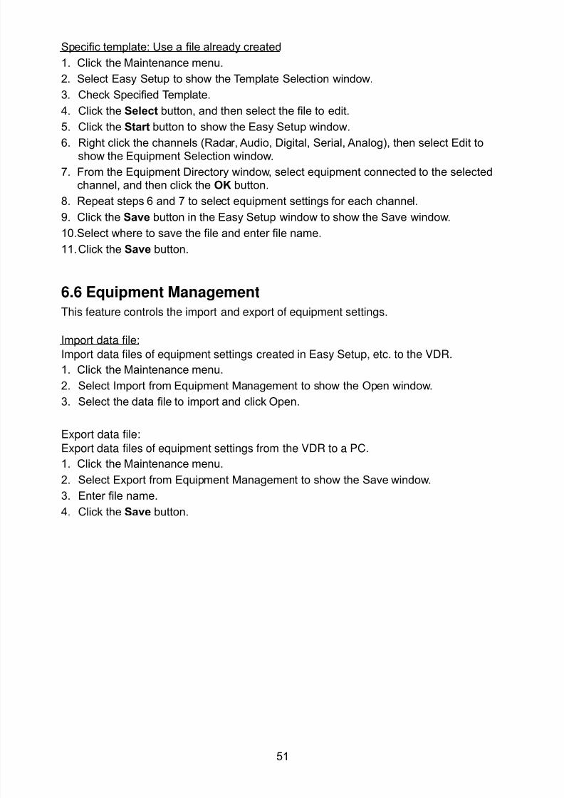
8102019 Ome44376d Vr3000 Mainte Cof26amp3bmol
httpslidepdfcomreaderfullome44376d-vr3000-mainte-cof26amp3bmol 5357
51
Specific template Use a file already created
1 Click the Maintenance menu
2 Select Easy Setup to show the Template Selection window
3 Check Specified Template
4 Click the Select button and then select the file to edit
5 Click the Start button to show the Easy Setup window
6 Right click the channels (Radar Audio Digital Serial Analog) then select Edit toshow the Equipment Selection window
7 From the Equipment Directory window select equipment connected to the selectedchannel and then click the OK button
8 Repeat steps 6 and 7 to select equipment settings for each channel
9 Click the Save button in the Easy Setup window to show the Save window
10Select where to save the file and enter file name
11 Click the Save button
66 Equipment Management
This feature controls the import and export of equipment settings
Import data file
Import data files of equipment settings created in Easy Setup etc to the VDR
1 Click the Maintenance menu
2 Select Import from Equipment Management to show the Open window
3 Select the data file to import and click Open
Export data file
Export data files of equipment settings from the VDR to a PC
1 Click the Maintenance menu
2 Select Export from Equipment Management to show the Save window
3 Enter file name
4 Click the Save button
8102019 Ome44376d Vr3000 Mainte Cof26amp3bmol
httpslidepdfcomreaderfullome44376d-vr3000-mainte-cof26amp3bmol 5457
52
67 PC_RAP
This feature enables the same operation of the RAP (Remote Alarm Panel) from a PC
Select PC_RAP from the Tool menu to show the PC_RAP window
The buttons in the PC_RAP window function as shown below
SAVE Stop recording in the area where recording is currently being done
ACK Silence audio alarm
The PC_RAP display shows the following information with LEDs
RAP_LEDs Display the status of LEDs on the RAPSave The Save button blinks yellow when pushed When the 4 memory
areas have data recorded to them the Save button lights orange when
pushed
Normal Lights (green) where there are no unconfirmed or not restored
alarms
Error Flashes (red) for not confirmed alarm Lights (red) for unrestored
alarm
8102019 Ome44376d Vr3000 Mainte Cof26amp3bmol
httpslidepdfcomreaderfullome44376d-vr3000-mainte-cof26amp3bmol 5557
53
Backup HDD Information Display status of backup HDD
Selected Display current recording area and its status in green for
normal operation and in red for abnormal operation
Size Display capacity of backup HDD
Alarm area displays unconfirmed alarms
Time Display time alarm was generatedNumber Display number of alarm
Name Display name of alarm
Pending Alarm displays the unrestored alarms out of confirmed alarms only
Time Display time alarm was generated
Number Display number of alarm
Name Display name of alarm
8102019 Ome44376d Vr3000 Mainte Cof26amp3bmol
httpslidepdfcomreaderfullome44376d-vr3000-mainte-cof26amp3bmol 5657
54
68 Other
Status Monitor
The status monitor feature provides comprehensive data about the status of the VDR
From the menu bar click Toolgt Status Monitor to show the Status Monitor window
The buttons in the Status Monitor window work as shown below
Reload Settings for automatic refreshing of the status monitor
ON Turn automatic refresh OFF
OFF The Status Monitor is refreshed every five seconds
Save Available when Reload ON is selected The contents of the Status Monitor can be
saved to a text fileUpdate Update the Status Monitor display
Close Close the Status Monitor display
8102019 Ome44376d Vr3000 Mainte Cof26amp3bmol
httpslidepdfcomreaderfullome44376d-vr3000-mainte-cof26amp3bmol 5757
VDR Error List
This feature compiles all the errors shown on the RAP for easy reference
Access from MenugtToolgtVDR Error List
The VDR error list contains the following information
NO Display the number of the error
Title Display the name of the error
Detail Display details about the error
Exchange Check
This feature removes the alarms generated when replacing the DRU or backup HDD
Access MenugtToolgtExchange Check select either DRU or Backup HDD and click OK
Reboot
Reboot the VDR
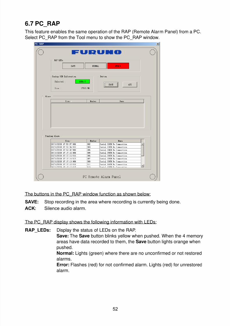
8102019 Ome44376d Vr3000 Mainte Cof26amp3bmol
httpslidepdfcomreaderfullome44376d-vr3000-mainte-cof26amp3bmol 5457
52
67 PC_RAP
This feature enables the same operation of the RAP (Remote Alarm Panel) from a PC
Select PC_RAP from the Tool menu to show the PC_RAP window
The buttons in the PC_RAP window function as shown below
SAVE Stop recording in the area where recording is currently being done
ACK Silence audio alarm
The PC_RAP display shows the following information with LEDs
RAP_LEDs Display the status of LEDs on the RAPSave The Save button blinks yellow when pushed When the 4 memory
areas have data recorded to them the Save button lights orange when
pushed
Normal Lights (green) where there are no unconfirmed or not restored
alarms
Error Flashes (red) for not confirmed alarm Lights (red) for unrestored
alarm
8102019 Ome44376d Vr3000 Mainte Cof26amp3bmol
httpslidepdfcomreaderfullome44376d-vr3000-mainte-cof26amp3bmol 5557
53
Backup HDD Information Display status of backup HDD
Selected Display current recording area and its status in green for
normal operation and in red for abnormal operation
Size Display capacity of backup HDD
Alarm area displays unconfirmed alarms
Time Display time alarm was generatedNumber Display number of alarm
Name Display name of alarm
Pending Alarm displays the unrestored alarms out of confirmed alarms only
Time Display time alarm was generated
Number Display number of alarm
Name Display name of alarm
8102019 Ome44376d Vr3000 Mainte Cof26amp3bmol
httpslidepdfcomreaderfullome44376d-vr3000-mainte-cof26amp3bmol 5657
54
68 Other
Status Monitor
The status monitor feature provides comprehensive data about the status of the VDR
From the menu bar click Toolgt Status Monitor to show the Status Monitor window
The buttons in the Status Monitor window work as shown below
Reload Settings for automatic refreshing of the status monitor
ON Turn automatic refresh OFF
OFF The Status Monitor is refreshed every five seconds
Save Available when Reload ON is selected The contents of the Status Monitor can be
saved to a text fileUpdate Update the Status Monitor display
Close Close the Status Monitor display
8102019 Ome44376d Vr3000 Mainte Cof26amp3bmol
httpslidepdfcomreaderfullome44376d-vr3000-mainte-cof26amp3bmol 5757
VDR Error List
This feature compiles all the errors shown on the RAP for easy reference
Access from MenugtToolgtVDR Error List
The VDR error list contains the following information
NO Display the number of the error
Title Display the name of the error
Detail Display details about the error
Exchange Check
This feature removes the alarms generated when replacing the DRU or backup HDD
Access MenugtToolgtExchange Check select either DRU or Backup HDD and click OK
Reboot
Reboot the VDR
8102019 Ome44376d Vr3000 Mainte Cof26amp3bmol
httpslidepdfcomreaderfullome44376d-vr3000-mainte-cof26amp3bmol 5557
53
Backup HDD Information Display status of backup HDD
Selected Display current recording area and its status in green for
normal operation and in red for abnormal operation
Size Display capacity of backup HDD
Alarm area displays unconfirmed alarms
Time Display time alarm was generatedNumber Display number of alarm
Name Display name of alarm
Pending Alarm displays the unrestored alarms out of confirmed alarms only
Time Display time alarm was generated
Number Display number of alarm
Name Display name of alarm
8102019 Ome44376d Vr3000 Mainte Cof26amp3bmol
httpslidepdfcomreaderfullome44376d-vr3000-mainte-cof26amp3bmol 5657
54
68 Other
Status Monitor
The status monitor feature provides comprehensive data about the status of the VDR
From the menu bar click Toolgt Status Monitor to show the Status Monitor window
The buttons in the Status Monitor window work as shown below
Reload Settings for automatic refreshing of the status monitor
ON Turn automatic refresh OFF
OFF The Status Monitor is refreshed every five seconds
Save Available when Reload ON is selected The contents of the Status Monitor can be
saved to a text fileUpdate Update the Status Monitor display
Close Close the Status Monitor display
8102019 Ome44376d Vr3000 Mainte Cof26amp3bmol
httpslidepdfcomreaderfullome44376d-vr3000-mainte-cof26amp3bmol 5757
VDR Error List
This feature compiles all the errors shown on the RAP for easy reference
Access from MenugtToolgtVDR Error List
The VDR error list contains the following information
NO Display the number of the error
Title Display the name of the error
Detail Display details about the error
Exchange Check
This feature removes the alarms generated when replacing the DRU or backup HDD
Access MenugtToolgtExchange Check select either DRU or Backup HDD and click OK
Reboot
Reboot the VDR
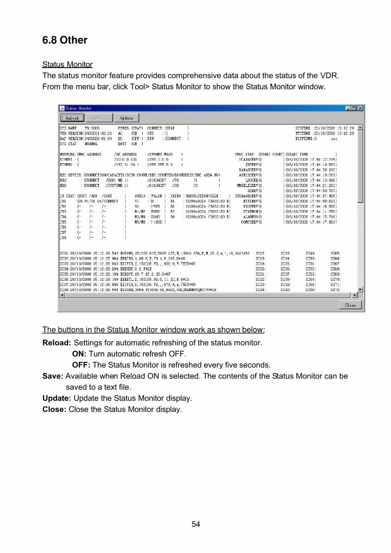
8102019 Ome44376d Vr3000 Mainte Cof26amp3bmol
httpslidepdfcomreaderfullome44376d-vr3000-mainte-cof26amp3bmol 5657
54
68 Other
Status Monitor
The status monitor feature provides comprehensive data about the status of the VDR
From the menu bar click Toolgt Status Monitor to show the Status Monitor window
The buttons in the Status Monitor window work as shown below
Reload Settings for automatic refreshing of the status monitor
ON Turn automatic refresh OFF
OFF The Status Monitor is refreshed every five seconds
Save Available when Reload ON is selected The contents of the Status Monitor can be
saved to a text fileUpdate Update the Status Monitor display
Close Close the Status Monitor display
8102019 Ome44376d Vr3000 Mainte Cof26amp3bmol
httpslidepdfcomreaderfullome44376d-vr3000-mainte-cof26amp3bmol 5757
VDR Error List
This feature compiles all the errors shown on the RAP for easy reference
Access from MenugtToolgtVDR Error List
The VDR error list contains the following information
NO Display the number of the error
Title Display the name of the error
Detail Display details about the error
Exchange Check
This feature removes the alarms generated when replacing the DRU or backup HDD
Access MenugtToolgtExchange Check select either DRU or Backup HDD and click OK
Reboot
Reboot the VDR
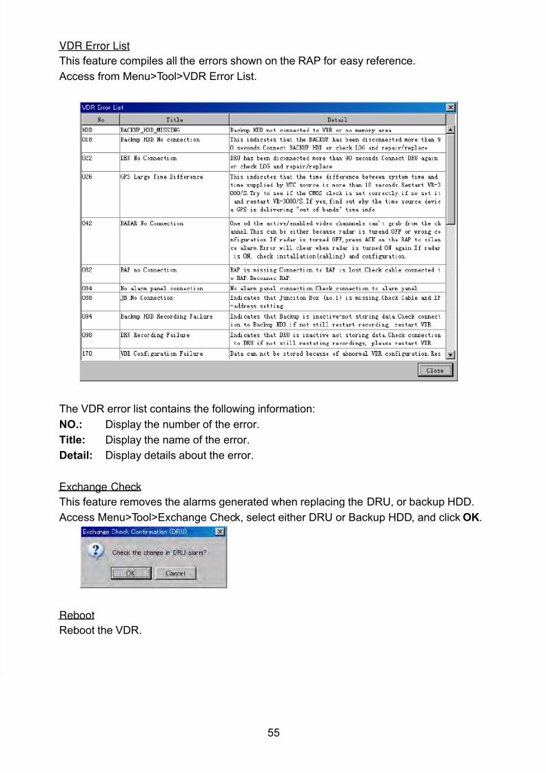
8102019 Ome44376d Vr3000 Mainte Cof26amp3bmol
httpslidepdfcomreaderfullome44376d-vr3000-mainte-cof26amp3bmol 5757
VDR Error List
This feature compiles all the errors shown on the RAP for easy reference
Access from MenugtToolgtVDR Error List
The VDR error list contains the following information
NO Display the number of the error
Title Display the name of the error
Detail Display details about the error
Exchange Check
This feature removes the alarms generated when replacing the DRU or backup HDD
Access MenugtToolgtExchange Check select either DRU or Backup HDD and click OK
Reboot
Reboot the VDR