Model-Based Analysis of a Stepwise Shutdown Logic · control). The process is driven again towards...
41
VTT WORKING PAPERS 115 Kim Björkman 1 , Juho Frits 2 , Janne Valkonen 1 , Keijo Heljanko 2 & Ilkka Niemelä 2 Model-Based Analysis of a Stepwise Shutdown Logic MODSAFE 2008 Work Report 1 VTT Technical Research Centre of Finland 2 Helsinki University of Tehcnology TKK Department of Information and Computer Science
Transcript of Model-Based Analysis of a Stepwise Shutdown Logic · control). The process is driven again towards...

VTT WORKING PAPERS 115VTT CREATES BUSINESS FROM TECHNOLOGY�Technology�and�market�foresight�•�Strategic�research�•�Product�and�service�development�•�IPR�and�licensing�•�Assessments,�testing,�inspection,�certification�•�Technology�and�innovation�management�•�Technology�partnership
•�•�•��VTT�WO
RKIN
G�PA
PERS�115�����M
OD
EL-BA
SED�A
NA
LYSIS�OF�A
�STEPWISE�SH
UTD
OW
N�LO
GIC
.�MO
DSA
FE�2008�WO
RK�R
EPOT
ISBN 978-951-38-7176-5 (URL: http://www.vtt.fi/publications/index.jsp) ISSN 1459-7683 (URL: http://www.vtt.fi/publications/index.jsp)
Kim Björkman1, Juho Frits2, Janne Valkonen1, Keijo Heljanko2 & Ilkka Niemelä2
Model-Based Analysis of a Stepwise Shutdown Logic
MODSAFE 2008 Work Report
1VTT Technical Research Centre of Finland2Helsinki University of Tehcnology TKK Department of Information and Computer Science

ISBN 978-951-38-7176-5 (URL: http://www.vtt.fi/publications/index.jsp) ISSN 1459-7683 (URL: http://www.vtt.fi/publications/index.jsp)
Copyright © VTT 2009
JULKAISIJA – UTGIVARE – PUBLISHER
VTT, Vuorimiehentie 5, PL 1000, 02044 VTT puh. vaihde 020 722 111, faksi 020 722 7001
VTT, Bergsmansvägen 5, PB 1000, 02044 VTT tel. växel 020 722 111, fax 020 722 7001
VTT Technical Research Centre of Finland, Vuorimiehentie 5, P.O. Box 1000, FI-02044 VTT, Finland phone internat. +358 20 722 111, fax +358 20 722 7001
Technical editing Maini Manninen
Series title, number and report code of publication
VTT Working Papers 115 VTT–WORK–115
Author(s) Kim Björkman, Juho Frits, Janne Valkonen, Keijo Heljanko & Ilkka Niemelä Title
Model-Based Analysis of a Stepwise Shutdown Logic MODSAFE 2008 Work Report Abstract Modern digitalized Instrumentation & Control (I&C) systems set new challenges for safety evaluation. Model checking is a promising formal method that can be used for verifying the correctness of system designs. A number of efficient model checking systems are available offering analysis tools that are able to determine automatically whether a given state machine model satisfies the desired safety properties. Model checking can also handle delays and other time-related operations, which are crucial in safety I&C systems and are challenging to design and verify.
Two types of model checking approaches are studied to verify safety logic designs involving timing aspects. The first approach uses timed automata as the modelling framework and the other employs finite state machines typically used in verifying hardware. The approaches are compared using two similar designs of a safety logic demonstrating how small changes in the design can lead to unexpected errors that are hard to detect without using model checking techniques. A straightforward approach to modelling such designs using timed automata and finite state machines is developed and the performance of the model checking tools when verifying the safety requirements of the designs is studied.
A safety case is a way of presenting a clear, defensible argument that a system is adequately safe to operate in its intended environment. Two safety case notations are compared and an exploratory safety case structure developed to test the methodology in practice and see how it suits for documenting the results of model checking. ISBN 978-951-38-7176-5 (URL: http://www.vtt.fi/publications/index.jsp)
Series title and ISSN Project number VTT Working Papers 1459-7683 (URL: http://www.vtt.fi/publications/index.jsp) 23743
Date Language Pages March 2009 English 36 p. + app. 3 p.
Name of project Commissioned by MODSAFE – Model-based safety evaluation of automation systems
Keywords Publisher safety evaluation, model checking, automation system, I&C, safety case, failure, NuSMV, UPPAAL
VTT Technical Research Centre of Finland P.O. Box 1000, FI-02044 VTT, Finland Phone internat. +358 20 722 4520 Fax +358 20 722 4374

5
Preface
This report has been prepared under the research project Model-Based Safety Evaluation of Automation Systems (MODSAFE) which is part of the Finnish Research Programme on Nuclear Power Plant Safety 2007–2010 (SAFIR2010). The aims of the project are to develop methods for model-based safety evaluation, apply the methods in realistic case studies, evaluate the suitability of formal model checking methods for Nuclear Power Plant (NPP) automation analysis, and develop recommendations for the practical application of the methods. This report introduces one of the systems investigated in the 2008 project year, summarizes the results of model checking and describes the safety case methodology.
We wish to express our gratitude to the representatives of the organizations who provided us with the case studies and all those who have given their valuable input in the meetings and discussions during the project.
Espoo, February 2009
Authors
6
Contents Preface ........................................................................................................................... 5
Abbreviations .................................................................................................................. 7
1. Introduction ............................................................................................................... 8
2. Description of the Stepwise Shutdown Logic .......................................................... 10
3. Model Checking ...................................................................................................... 13 3.1 Symbolic Model Checking......................................................................................................... 13 3.2 Timed Automata Model Checking ............................................................................................. 14
4. Modelling of the Stepwise Shutdown Logic............................................................. 15 4.1 UPPAAL Model of the System .................................................................................................. 15
4.1.1 Timer 1 ....................................................................................................................... 15 4.1.2 Timer 2 ....................................................................................................................... 17 4.1.3 Input Automaton......................................................................................................... 18 4.1.4 Flow Input Automaton ................................................................................................ 18
4.2 NuSMV Model of the System.................................................................................................... 19 4.3 Verified Properties .................................................................................................................... 21 4.4 Comparison of Results.............................................................................................................. 22 4.5 Failure Models .......................................................................................................................... 23
5. Safety Cases........................................................................................................... 26 5.1 Safety Case Development and Model Checking....................................................................... 26 5.2 Comparing Safety Case Notations............................................................................................ 27 5.3 Making an Example Safety Case of the Stepwise Shutdown Logic .......................................... 28
6. Conclusions............................................................................................................. 32
Acknowledgements....................................................................................................... 34
References ................................................................................................................... 35
Appendices
Appendix A: System Declarations of the UPPAAL Model Appendix B: Local Declarations of the Input Automaton of the UPPAAL Model
1. Introduction
7
Abbreviations
ASCE Assurance and Safety Case Environment
BDD Binary Decision Diagram
CAE Claims Argument Evidence
CTL Computation Tree Logic
GSN Goal Structuring Notation
IAEA International Atomic Energy Agency
I&C Instrumentation & Control
LTL Linear Temporal Logic
MODSAFE Model-Based Safety Evaluation of Automation Systems
NPP Nuclear Power Plant
PC Personal Computer
SAFIR2010 Finnish Research Programme on Nuclear Power Plant Safety 2007–2010
SAT Propositional Satisfiability
SMV Symbolic Model Verifier
TCTL Timed Computation Tree Logic
1. Introduction
8
1. Introduction
Modern digitalized Instrumentation & Control (I&C) systems are employed in critical applications creating new challenges for safety evaluation. However, such validation work still relies heavily on subjective evaluation which covers only a limited part of the possible behaviours of the system and therefore more rigorous formal methods are required. Such formal methods have been studied (see, e.g., Valkonen et al. [19] for an overview) but they are not yet widely used. Model checking [11] is a promising formal method that can be used for verifying the correctness of system designs. It has not previously been applied in the safety evaluation of nuclear power plant (NPP) automation systems (at least in Finland) but internationally it has been used in verifying the correct behaviour of, e.g., hardware and microprocessor designs, data communications protocols, and operating system device drivers.
A number of efficient model checking systems are available offering analysis tools that are able to determine automatically whether a given state machine model satisfies desired safety properties. Model checking can also handle delays and other time-related operations, which are crucial in safety I&C systems and are challenging to design and verify.
The objective of the Model-Based Safety Evaluation of Automation Systems (MODSAFE) project is to evaluate and develop methods based on formal model checking and apply them in the safety analysis of NPP safety automation (I&C). The purpose is to get a group of methods and tools that can support the practical safety evaluation work and benefit utilities, regulator, and vendors.
The goals of the project for the first two years included reviewing the state of the art in employing formal methods and models for safety evaluation of industrial and nuclear safety systems [19], developing a basic methodology for applying model checking to safety evaluation, and studying the feasibility of the approach [20]. The project focuses on a number of case studies which direct the development of the required methodology and serve as benchmarks for evaluating the feasibility and applicability of the approach.
This report summarizes the experiences gained in the MODSAFE 2008 project of the SAFIR2010 research programme while working on a case study called “Reactor Stepwise Shutdown Logic”. The rest of the report is structured as follows. Section 2

1. Introduction
9
presents the shutdown logic system. Section 3 provides some background information on model checking. Section 4 discusses modelling of the stepwise shutdown logic system and model checking its key safety properties. Section 5 describes two approaches to developing a safety case for the case and Section 6 contains the conclusions.
Some of the results described in Sections 2 and 4 are presented in Björkman et al. [8].
2. Description of the Stepwise Shutdown Logic
10
2. Description of the Stepwise Shutdown Logic
The safety-related system analysed in the research is a safety logic called the stepwise shutdown logic. It is used for the stepwise control of the process towards the normal operating state in the case of process disturbances. The system is triggered when one of the process variables, e.g. the measurement of reactor temperature, deviates from the values set for normal operation. The purpose of the system is to reduce the possibility of the process reaching a state where the actual shutdown function of the process is required. The stepwise shutdown logic is a softer way to control the process and provides savings in time and cost compared with the actual shutdown. Both shutdown systems use partly the same process variables but in the stepwise shutdown the limit values are reached earlier.
The stepwise shutdown logic consists of a set of input signals and their processing and voting logics, and measurement threshold elements. The input signals are related to different process variables, such as the reactor temperature and pressure, and reactor water inflow. Besides providing signal values (analogue and binary), the underlying platform allows also the processing of information on the validity of the signals. The used signal validity information is the fault status, which enables the identification of faulty signals, and the processing of faulty signals according to predetermined rules. For example, if all signals of the same measurement the fault status set, the default value of the output of a process variable measurement is zero to avoid unnecessary shutdowns of the process.
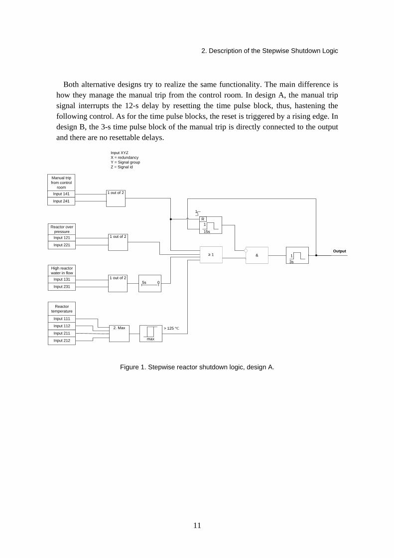
Figures 1 and 2 illustrate two alternative logic diagrams, A and B, that have been designed for implementing the stepwise shutdown. The stepwise shutdown is performed when the measurements of the process variables reach and remain for a certain period over their releasing limit values. At first the process is driven towards a safer state for 3 s. After that, there is a delay of 12 s (the time left of the 15-s time pulse block after the 3-s control). The process is driven again towards a safer state for 3 s if the criteria for the stepwise shutdown are still valid after the delay. This procedure is repeated until the process is back in the safe state or completely shut down (or the actual shutdown is triggered). During the 12-s delay, the following 3-s control can be accelerated through a manual trip from the control room.
2. Description of the Stepwise Shutdown Logic
11
Both alternative designs try to realize the same functionality. The main difference is how they manage the manual trip from the control room. In design A, the manual trip signal interrupts the 12-s delay by resetting the time pulse block, thus, hastening the following control. As for the time pulse blocks, the reset is triggered by a rising edge. In design B, the 3-s time pulse block of the manual trip is directly connected to the output and there are no resettable delays.
3s
15s
2. Max
1 out of 2
1 out of 2
max
> 125 °C
Input XYZX = redundancyY = Signal groupZ = Signal id
≥ 1 &
1
1
1 out of 205s
R
1
Output
Manual trip from control
roomInput 141
Input 241
Reactor temperature
Input 111
Input 112
Reactor over pressure Input 121
Input 221
Input 211
Input 212
High reactor water in flow
Input 131
Input 231
Figure 1. Stepwise reactor shutdown logic, design A.

2. Description of the Stepwise Shutdown Logic
12
3s
15s
Output
2. Max
1 out of 2
1 out of 2
1 out of 2
05s
max > 125 °C
Input XYZX = redundancyY = Signal groupZ = Signal id
≥ 1 & ≥ 1
1
1
3s
1
Manual trip from control
roomInput 141
Input 241
Reactor temperature
Input 111
Input 112
Reactor over pressure
Input 121
Input 221
Input 211
Input 212
High reactor water inflow
Input 131
Input 231
Figure 2. Stepwise reactor shutdown logic, design B.
The stepwise shutdown system is a two-redundant system. Both redundancies have their own set of input signals that are independent of each other. In addition, the execution of the control logic of both redundancies is separated to a set of dedicated computers. The computers participating in the execution of the control logic are illustrated in Figure 3. The control room computers enable the manual trip functionality. The actual logic is processed in the logic processing computers.
Figure 3. Computer architecture.

3. Model Checking
13
3. Model Checking
Model checking [11] is a computer-aided verification method developed to formally verify the correct functioning of a system design model by examining all of its possible behaviours. Model checking was independently discovered by two research groups in the early 1980s [12, 17]. The models used in model checking are quite similar to those used in simulation, as basically the model must describe the behaviour of the system design for all sequences of inputs. However, unlike simulation, model checkers examine the behaviour of the system design with all input sequences and compare it with the system specification. In model checking, at least in principle, the analysis can be fully automated with computer-aided tools. The specification is expressed in a suitable specification language, temporal logics being a prime example, describing the allowed behaviours of a system. Given a model and a specification as input, a model checking algorithm decides whether the system violates its specification or not. If none of the behaviours of the system violate the given specification, the (model of the) system is correct. Otherwise the model checker will automatically give a counter-example execution of the system demonstrating why the property is violated. The MODSAFE project used two model checkers, NuSMV originally designed for hardware model checking and UPPAAL which supports model checking of timed automata. These tools are introduced below.
3.1 Symbolic Model Checking
NuSMV [10, 16] is a state-of-the-art symbolic model checker that supports synchronous state machine models where the real-time behaviour has to be modelled with discrete time steps using explicit counter variables that are incremented at a common clock frequency. NuSMV supports model checking using both Linear Temporal Logic (LTL) and Computation Tree Logic (CTL) [11], making it quite flexible in expressing design specifications. The model checking algorithms employed in this work are based on symbolically representing and exploring the state space of the system by using Binary Decision Diagrams (BDDs) [9, 15]. In addition, SAT (Propositional Satisfiability)-

3. Model Checking
14
based bounded model checking [5] is also supported by NuSMV [6] for finding bugs in larger designs. The sophisticated model checking techniques used by NuSMV can handle well non-determinism induced by free input variables but modelling the real-time aspects can be more challenging due to the inherently discrete time nature of the synchronous state machine model employed by NuSMV.
3.2 Timed Automata Model Checking
UPPAAL [18] is a model checking tool for timed systems based on modelling the system as a network of timed automata that communicate through message channels and shared variables. The timed automata have a finite control structure and real-valued clocks [4] making the modelling of timers fairly straightforward. Networks of timed automata can express the real-time behaviour of the system in continuous time and still be automatically analysed. This is feasible because all the possible behaviours of the system can be captured using a finite graph where different clock valuations with, intuitively, the same behaviour are grouped into a finite number of equivalence classes called regions [4]. The model checking algorithms use symbolic methods to compactly represent the clock valuations associated with each state of the system in quite a memory efficient manner. The model checking algorithms employed inside UPPAAL [3, 14] are able to check a subset of the temporal logic TCTL (Timed Computation Tree Logic) [3] by explicit state model checking that explicitly traverses the finite graph induced by the behaviour of the system. The main strength of UPPAAL is in analysing the complex timing behaviour of a system. However, it is not too well suited to systems with a very high amount of non-determinism as induced by, e.g., reading a large number of input variables (sensor readings) provided by the environment because each combination of inputs is explicitly explored by the employed model checking algorithms.
4. Modelling of the Stepwise Shutdown Logic
15
4. Modelling of the Stepwise Shutdown Logic
4.1 UPPAAL Model of the System
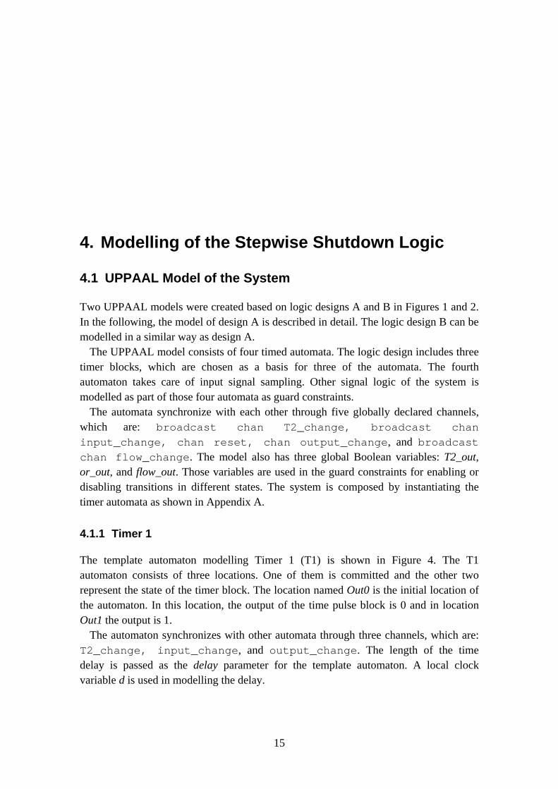
Two UPPAAL models were created based on logic designs A and B in Figures 1 and 2. In the following, the model of design A is described in detail. The logic design B can be modelled in a similar way as design A.
The UPPAAL model consists of four timed automata. The logic design includes three timer blocks, which are chosen as a basis for three of the automata. The fourth automaton takes care of input signal sampling. Other signal logic of the system is modelled as part of those four automata as guard constraints.
The automata synchronize with each other through five globally declared channels, which are: broadcast chan T2_change, broadcast chan input_change, chan reset, chan output_change, and broadcast chan flow_change. The model also has three global Boolean variables: T2_out, or_out, and flow_out. Those variables are used in the guard constraints for enabling or disabling transitions in different states. The system is composed by instantiating the timer automata as shown in Appendix A.
4.1.1 Timer 1
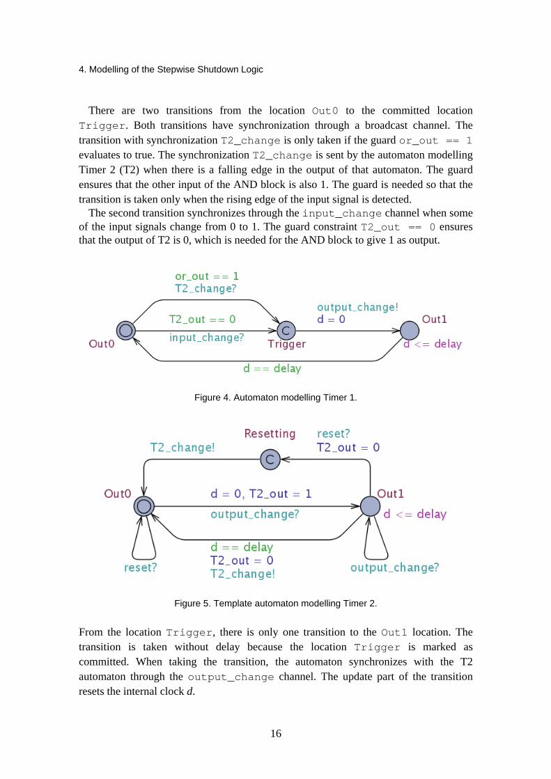
The template automaton modelling Timer 1 (T1) is shown in Figure 4. The T1 automaton consists of three locations. One of them is committed and the other two represent the state of the timer block. The location named Out0 is the initial location of the automaton. In this location, the output of the time pulse block is 0 and in location Out1 the output is 1.
The automaton synchronizes with other automata through three channels, which are: T2_change, input_change, and output_change. The length of the time delay is passed as the delay parameter for the template automaton. A local clock variable d is used in modelling the delay.
4. Modelling of the Stepwise Shutdown Logic
16
There are two transitions from the location Out0 to the committed location Trigger. Both transitions have synchronization through a broadcast channel. The transition with synchronization T2_change is only taken if the guard or_out == 1 evaluates to true. The synchronization T2_change is sent by the automaton modelling Timer 2 (T2) when there is a falling edge in the output of that automaton. The guard ensures that the other input of the AND block is also 1. The guard is needed so that the transition is taken only when the rising edge of the input signal is detected.
The second transition synchronizes through the input_change channel when some of the input signals change from 0 to 1. The guard constraint T2_out == 0 ensures that the output of T2 is 0, which is needed for the AND block to give 1 as output.
Figure 4. Automaton modelling Timer 1.
Figure 5. Template automaton modelling Timer 2.
From the location Trigger, there is only one transition to the Out1 location. The transition is taken without delay because the location Trigger is marked as committed. When taking the transition, the automaton synchronizes with the T2 automaton through the output_change channel. The update part of the transition resets the internal clock d.
4. Modelling of the Stepwise Shutdown Logic
17
In the Out1 location the output of the timer block is 1. The Out1 location contains an invariant constraint d <= delay and the outgoing transition has a guard constraint d == delay. These two constraints force the automaton to be in location Out1 for exactly delay time units and after the time has passed the automaton must take the transition back to the Out0 location.
4.1.2 Timer 2
The template automaton modelling Timer 2 (T2) is shown in Figure 5. The automaton takes as a parameter the length of the time pulse. The automaton has three locations. Locations Out0 and Out1 represent the output states 0 and 1 just as in T1. The third location, called Resetting, forces the synchronizations to happen in the proper order.
If the automaton is in the Out0 location and it receives the output_change synchronization, it takes a transition to the Out1 location. This transition resets the clock d and sets the T2_out variable to value 1. There is also a transition from Out1 back to itself with synchronization output_change because the timer block disregards the rising edge of the input when the output is 1. The automaton sends the T2_change synchronization when the output of the block changes from 1 to 0 because only this change can cause the input signal of the T1 to change from 0 to 1.
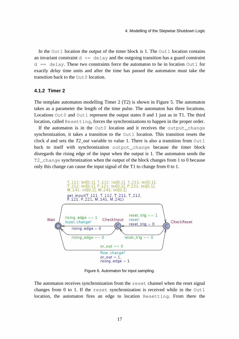
Figure 6. Automaton for input sampling.
The automaton receives synchronization from the reset channel when the reset signal changes from 0 to 1. If the reset synchronization is received while in the Out1 location, the automaton fires an edge to location Resetting. From there the
4. Modelling of the Stepwise Shutdown Logic
18
automaton immediately transfers to Out1 sending the T2_change synchronization which is received by the T1 automaton.
4.1.3 Input Automaton
The Input automaton assigns values for input variables non-deterministically. The Input automaton has three locations as shown in Figure 6. Normally the automaton is in the Wait location and it can take a transition to location CheckReset anytime. During the transition input variables are given values non-deterministically. Those variables are T_111, T_112, T_211, T_212, P_121, P_221, M_141, and M_241. The values of the variables are used in the update part of the edge where a function get_input is invoked. The function calculates the output of the OR gate (variable or_out) based on the values of the inputs which are passed as parameters to the function. The function get_input is declared in Appendix B.
From the CheckReset location the automaton takes one of the two transitions leading to another committed location CheckInput, depending on the value of the reset_trig variable. If reset_trig equals to true, the manual trip push button has been pushed and the automaton sends a reset synchronization.
The next transition leading back to the location Wait is taken depending on the value of the rising_edge variable, which is calculated in the get_input function. If the variable equals to true, the automaton sends an input_change synchronization indicating that the output of the OR gate has changed from 0 to 1.
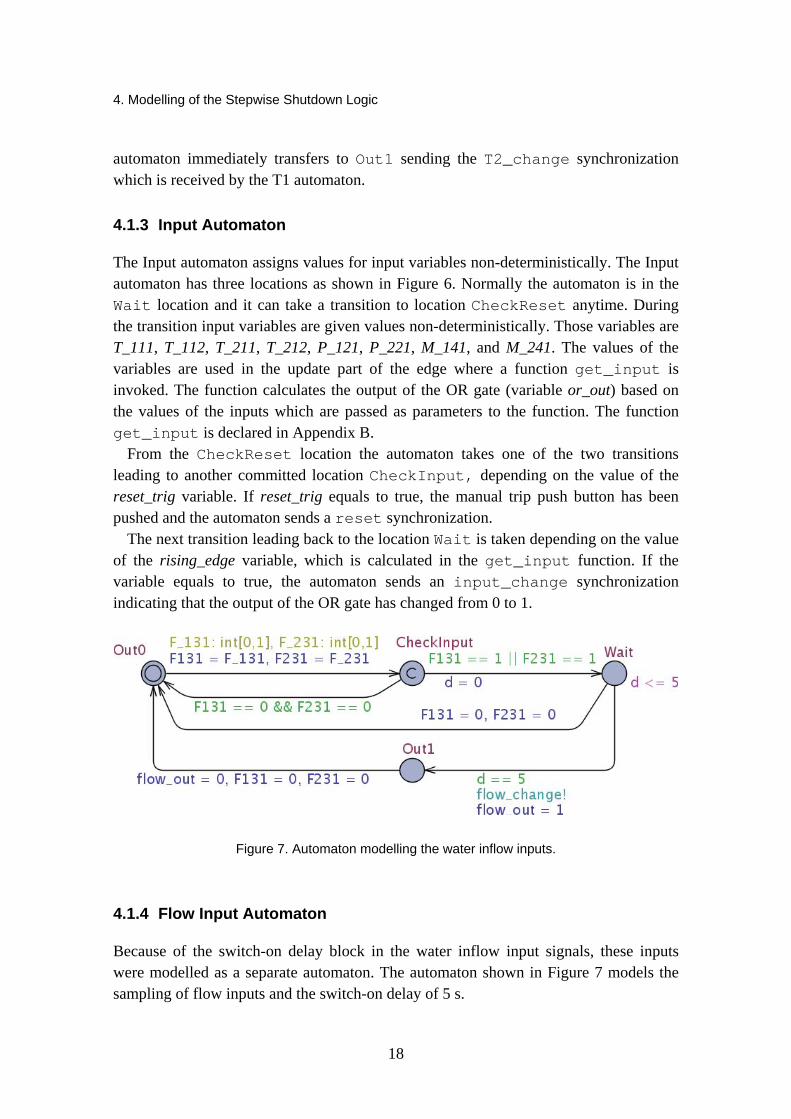
Figure 7. Automaton modelling the water inflow inputs.
4.1.4 Flow Input Automaton
Because of the switch-on delay block in the water inflow input signals, these inputs were modelled as a separate automaton. The automaton shown in Figure 7 models the sampling of flow inputs and the switch-on delay of 5 s.

4. Modelling of the Stepwise Shutdown Logic
19
The automaton consists of four locations. Locations Out0 and Out1 represent the states of the output of the switch-on delay block being 0 and 1. In the edge from Out0 to CheckInput, values for the variables F131 and F231 are given. From the CheckInput location, the automaton takes a transition depending on the values of those variables. If both the inputs are 0, the automaton takes a transition back to the Out0 location. Otherwise the automaton transfers to location Wait.
In location Wait the automaton waits for five time units until it takes a transition to Out1 sending a flow_change synchronization. The edge from Wait to Out0 represents the situation when the inputs change back to 0 before the 5-s delay has passed. From the Out1 location, the automaton transfers back to Out0 and sets the values of the variables back to 0.
4.2 NuSMV Model of the System
Two NuSMV models of the stepwise shutdown system were built based on the logic diagrams presented in Figures 1 and 2. The models comprised a set of modules that are collections of declarations, constraints and specifications. Both models were divided into several modules according to the process variable measurements. Since a module can contain instances of other modules, a structural hierarchy was constructed. Figure 8 below illustrates the modules and their hierarchy.
Figure 8. NuSMV module hierarchy.
4. Modelling of the Stepwise Shutdown Logic
20
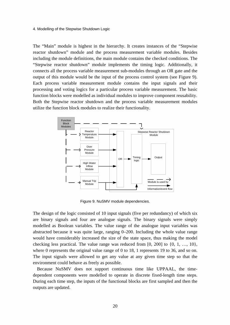
The “Main” module is highest in the hierarchy. It creates instances of the “Stepwise reactor shutdown” module and the process measurement variable modules. Besides including the module definitions, the main module contains the checked conditions. The “Stepwise reactor shutdown” module implements the timing logic. Additionally, it connects all the process variable measurement sub-modules through an OR gate and the output of this module would be the input of the process control system (see Figure 9). Each process variable measurement module contains the input signals and their processing and voting logics for a particular process variable measurement. The basic function blocks were modelled as individual modules to improve component reusability. Both the Stepwise reactor shutdown and the process variable measurement modules utilize the function block modules to realize their functionality.
Reactor Temperature
Module
High Water Inflow
Module
Over PressureModule
Stepwise Reactor Shutdown Module
Function Block
Modules
OR Timing logic
Output
Information/event flow
Module is used byManual TripModule
Figure 9. NuSMV module dependencies.
The design of the logic consisted of 10 input signals (five per redundancy) of which six are binary signals and four are analogue signals. The binary signals were simply modelled as Boolean variables. The value range of the analogue input variables was abstracted because it was quite large, ranging 0–200. Including the whole value range would have considerably increased the size of the state space, thus making the model checking less practical. The value range was reduced from [0, 200] to {0, 1, …, 10}, where 0 represents the original value range of 0 to 18, 1 represents 19 to 36, and so on. The input signals were allowed to get any value at any given time step so that the environment could behave as freely as possible.
Because NuSMV does not support continuous time like UPPAAL, the time-dependent components were modelled to operate in discrete fixed-length time steps. During each time step, the inputs of the functional blocks are first sampled and then the outputs are updated.
4. Modelling of the Stepwise Shutdown Logic
21
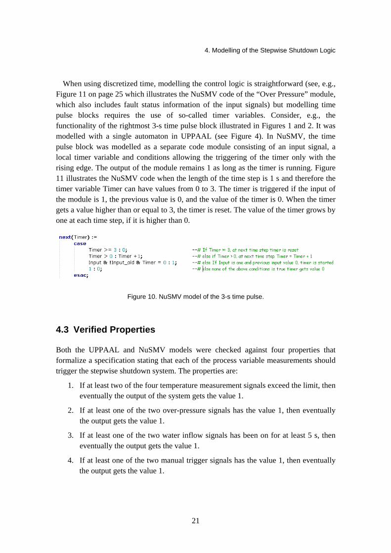
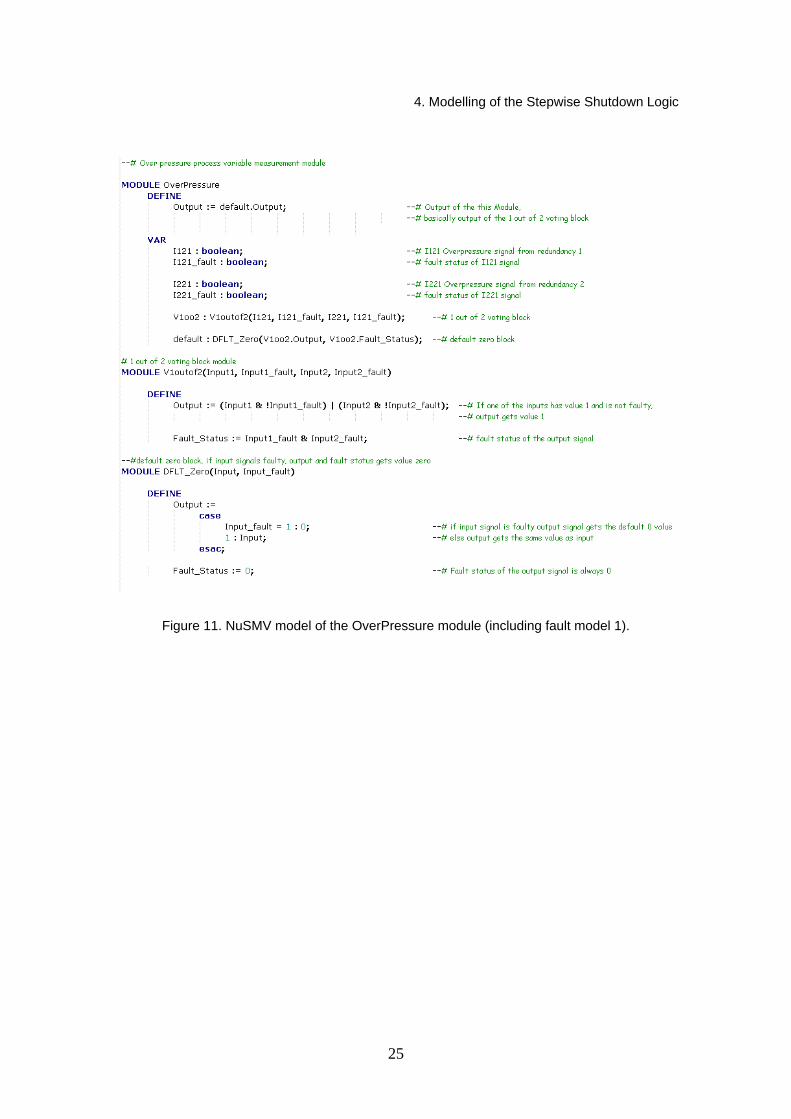
When using discretized time, modelling the control logic is straightforward (see, e.g., Figure 11 on page 25 which illustrates the NuSMV code of the “Over Pressure” module, which also includes fault status information of the input signals) but modelling time pulse blocks requires the use of so-called timer variables. Consider, e.g., the functionality of the rightmost 3-s time pulse block illustrated in Figures 1 and 2. It was modelled with a single automaton in UPPAAL (see Figure 4). In NuSMV, the time pulse block was modelled as a separate code module consisting of an input signal, a local timer variable and conditions allowing the triggering of the timer only with the rising edge. The output of the module remains 1 as long as the timer is running. Figure 11 illustrates the NuSMV code when the length of the time step is 1 s and therefore the timer variable Timer can have values from 0 to 3. The timer is triggered if the input of the module is 1, the previous value is 0, and the value of the timer is 0. When the timer gets a value higher than or equal to 3, the timer is reset. The value of the timer grows by one at each time step, if it is higher than 0.
Figure 10. NuSMV model of the 3-s time pulse.
4.3 Verified Properties
Both the UPPAAL and NuSMV models were checked against four properties that formalize a specification stating that each of the process variable measurements should trigger the stepwise shutdown system. The properties are:
1. If at least two of the four temperature measurement signals exceed the limit, then eventually the output of the system gets the value 1.
2. If at least one of the two over-pressure signals has the value 1, then eventually the output gets the value 1.
3. If at least one of the two water inflow signals has been on for at least 5 s, then eventually the output gets the value 1.
4. If at least one of the two manual trigger signals has the value 1, then eventually the output gets the value 1.
4. Modelling of the Stepwise Shutdown Logic
22
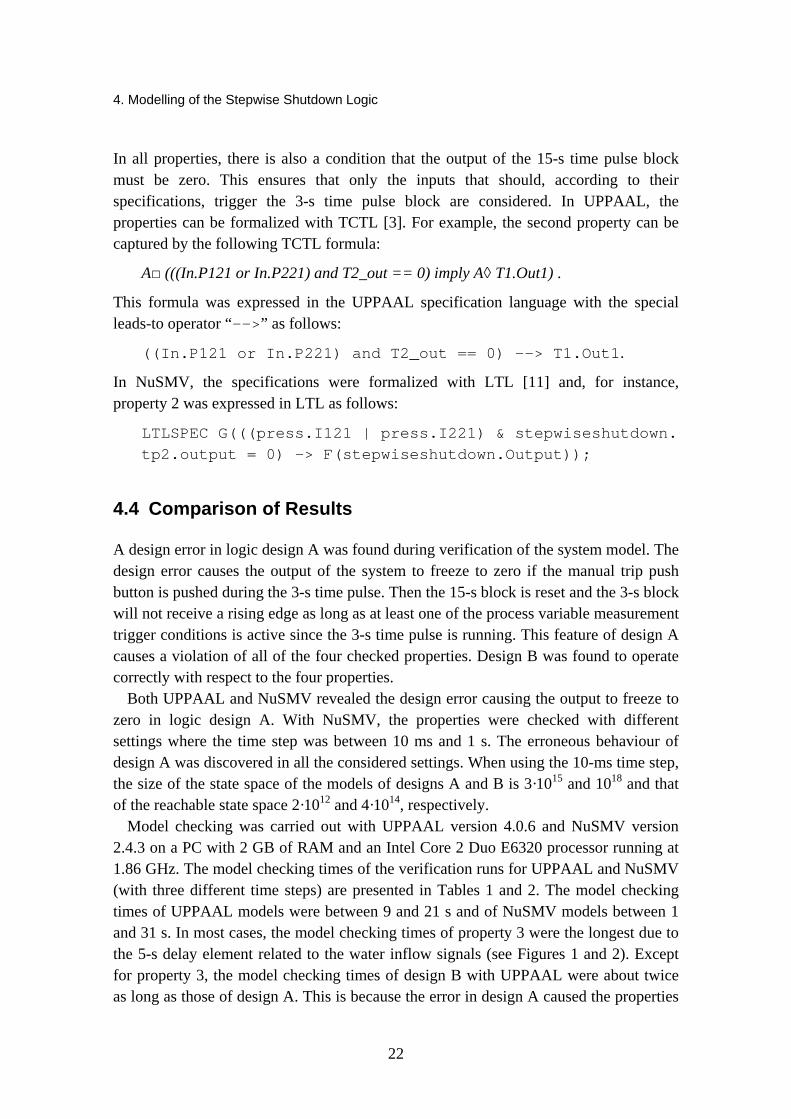
In all properties, there is also a condition that the output of the 15-s time pulse block must be zero. This ensures that only the inputs that should, according to their specifications, trigger the 3-s time pulse block are considered. In UPPAAL, the properties can be formalized with TCTL [3]. For example, the second property can be captured by the following TCTL formula:
A□ (((In.P121 or In.P221) and T2_out == 0) imply A◊ T1.Out1) .
This formula was expressed in the UPPAAL specification language with the special leads-to operator “-->” as follows:
((In.P121 or In.P221) and T2_out == 0) --> T1.Out1.
In NuSMV, the specifications were formalized with LTL [11] and, for instance, property 2 was expressed in LTL as follows:
LTLSPEC G(((press.I121 | press.I221) & stepwiseshutdown. tp2.output = 0) -> F(stepwiseshutdown.Output));
4.4 Comparison of Results
A design error in logic design A was found during verification of the system model. The design error causes the output of the system to freeze to zero if the manual trip push button is pushed during the 3-s time pulse. Then the 15-s block is reset and the 3-s block will not receive a rising edge as long as at least one of the process variable measurement trigger conditions is active since the 3-s time pulse is running. This feature of design A causes a violation of all of the four checked properties. Design B was found to operate correctly with respect to the four properties.
Both UPPAAL and NuSMV revealed the design error causing the output to freeze to zero in logic design A. With NuSMV, the properties were checked with different settings where the time step was between 10 ms and 1 s. The erroneous behaviour of design A was discovered in all the considered settings. When using the 10-ms time step, the size of the state space of the models of designs A and B is 3·1015 and 1018 and that of the reachable state space 2·1012 and 4·1014, respectively.
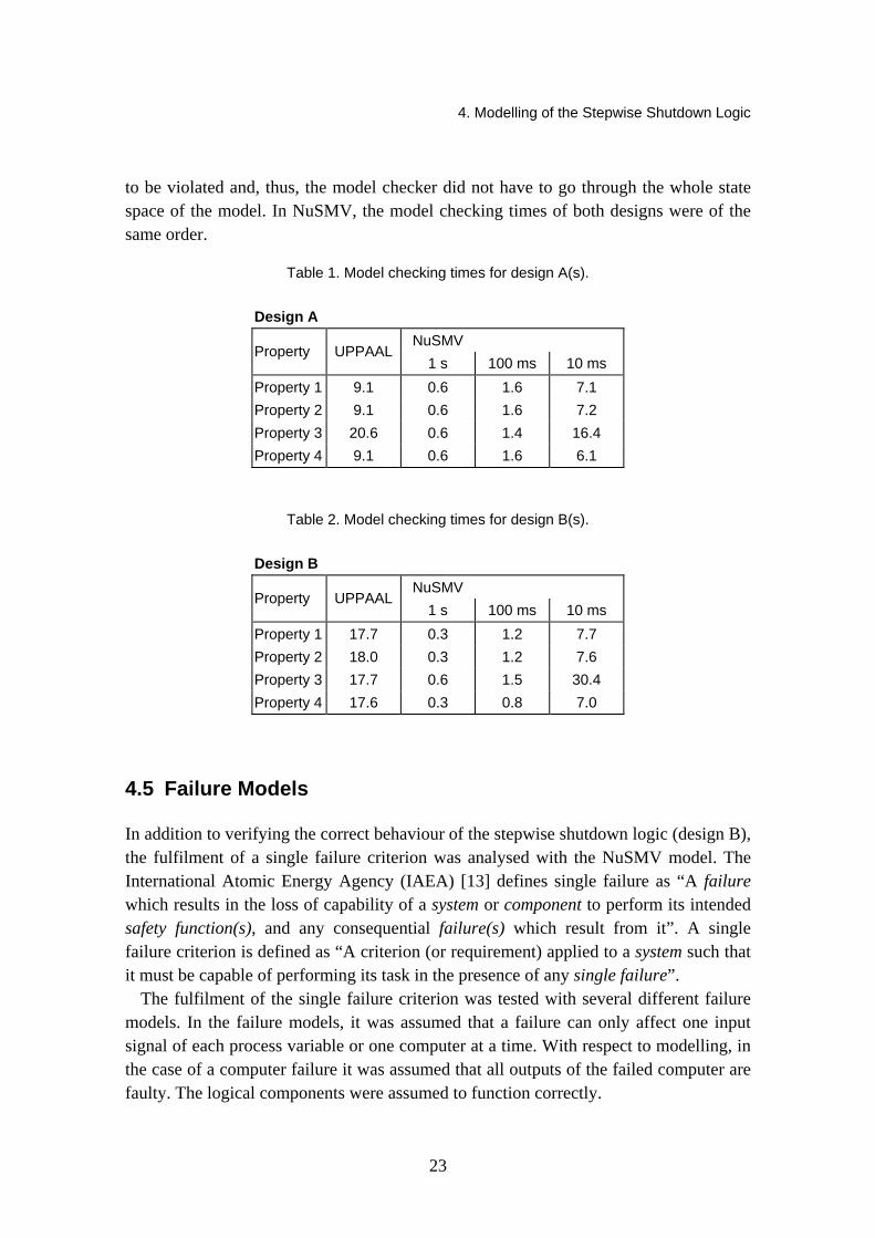
Model checking was carried out with UPPAAL version 4.0.6 and NuSMV version 2.4.3 on a PC with 2 GB of RAM and an Intel Core 2 Duo E6320 processor running at 1.86 GHz. The model checking times of the verification runs for UPPAAL and NuSMV (with three different time steps) are presented in Tables 1 and 2. The model checking times of UPPAAL models were between 9 and 21 s and of NuSMV models between 1 and 31 s. In most cases, the model checking times of property 3 were the longest due to the 5-s delay element related to the water inflow signals (see Figures 1 and 2). Except for property 3, the model checking times of design B with UPPAAL were about twice as long as those of design A. This is because the error in design A caused the properties
4. Modelling of the Stepwise Shutdown Logic
23
to be violated and, thus, the model checker did not have to go through the whole state space of the model. In NuSMV, the model checking times of both designs were of the same order.
Table 1. Model checking times for design A(s).
Design A NuSMV
Property UPPAAL1 s 100 ms 10 ms
Property 1 9.1 0.6 1.6 7.1 Property 2 9.1 0.6 1.6 7.2 Property 3 20.6 0.6 1.4 16.4 Property 4 9.1 0.6 1.6 6.1
Table 2. Model checking times for design B(s).
Design B NuSMV
Property UPPAAL1 s 100 ms 10 ms
Property 1 17.7 0.3 1.2 7.7 Property 2 18.0 0.3 1.2 7.6 Property 3 17.7 0.6 1.5 30.4 Property 4 17.6 0.3 0.8 7.0
4.5 Failure Models
In addition to verifying the correct behaviour of the stepwise shutdown logic (design B), the fulfilment of a single failure criterion was analysed with the NuSMV model. The International Atomic Energy Agency (IAEA) [13] defines single failure as “A failure which results in the loss of capability of a system or component to perform its intended safety function(s), and any consequential failure(s) which result from it”. A single failure criterion is defined as “A criterion (or requirement) applied to a system such that it must be capable of performing its task in the presence of any single failure”.
The fulfilment of the single failure criterion was tested with several different failure models. In the failure models, it was assumed that a failure can only affect one input signal of each process variable or one computer at a time. With respect to modelling, in the case of a computer failure it was assumed that all outputs of the failed computer are faulty. The logical components were assumed to function correctly.

4. Modelling of the Stepwise Shutdown Logic
24
The starting point of the model was that no faults were present. The original model was evolved with more challenging fault models by considering increasingly more complicated fault scenarios. Different faults were classified according to their effect and diagnostic perceptivity. The following three models were considered:
1. All failures are detected, failed signals get a non-deterministic value, and input signals or computers may fail or recover at any time step.
2. Failures may remain undetected, failed signals keep their previous values, and input signals or computers may fail or recover at any time step.
3. Failures may remain undetected, failed signals get a non-deterministic value, and input signals or computers may fail or recover at any time step.
To model faults, each input signal was given an additional Boolean value that represented the fault status of the signal (see Figure 11). The NuSMV model was checked with each of the failure models present against two properties that formalize a specification declaring that the stepwise shutdown logic should fulfil the single failure criteria. The properties are:
1. A single failure should not spuriously trigger the stepwise shutdown. 2. A single failure should not prevent the actual execution of the stepwise shutdown.
Design B fulfilled both of the single failure criterion properties completely with failure models 1 and 2. With failure model 3, the design did not fulfil property 1 because a single undetected faulty binary signal with value 1 could spuriously trigger the stepwise shutdown system. As the design is two-redundant based on 1 out of 2 voting, this property cannot even be expected to be fulfilled. However, in this case, the system fails in the safe direction. With failure model 3, design B fulfils property 2, i.e. no failures with dangerous consequences were discovered.
The introduction of the failure models increased the size of the state space. When using the 10-ms time step, the state space of design B was 2·1036 and the model checking times were between 1 s and 4 h. The longest model checking times were measured for property 1 with failure model 3 (including computer failures), when the time step was 10 ms; however, in this case the value range of the analogue signals was further reduced to [0, 1, 2, 3] to make the model checking more practicable.
4. Modelling of the Stepwise Shutdown Logic
25
Figure 11. NuSMV model of the OverPressure module (including fault model 1).

5. Safety Cases
26
5. Safety Cases
The general definitions of a safety case [1, 7] say that it is a way of presenting a clear, defensible argument that a system is adequately safe to operate in its intended environment. A safety case document contains all the necessary information for justifying the safety of a system together with an argument that explains how the available evidence supports the safety claims.
Earlier in the MODSAFE project (2007), formal methods and models applied in the safety evaluation of industrial and nuclear safety systems were reviewed [19]. As part of the review, the concept of a safety case was introduced and considered.
The primary objective of trying the safety case methodology for the stepwise shutdown system (described in Section 2) was to get experience on how the safety case development proceeds in practice, how difficult it is, and how the ASCE (Assurance and Safety Case Environment) tool [2] could be used for supporting the safety case development. The purpose was not to make a complete safety case of the system but to try the safety case development in practice, get information on the different features of the development process and utilize the experience later for reporting the results of model checking.
This section makes a general comparison of two safety case methodologies, Claim Argument Evidence (CAE) and Goal Structuring Notation (GSN), and describes the development of an exploratory safety case of the stepwise shutdown logic.
5.1 Safety Case Development and Model Checking
The general definition of a safety case refers to making it “for providing evidence that the system is adequately safe for a given application and environment over its lifetime”. This means making a safety case as complete as reasonably possible and taking all the possible viewpoints and circumstances into account. Thus, safety cases may contain several different types of evidence, and the results of model checking can be used for supporting certain goals. However, the role of model checking in safety case creation is limited because only certain features of the system can be modelled and model checked.

5. Safety Cases
27
Model checking suits well certain types of verification tasks but other evidence is needed to fully support high-level safety claims. The safety case notation could be effectively used for documenting the results of model checking. Then, the objective is not to consider extensively all the viewpoints for verifying the whole system but to concentrate on those aspects where model checking could help in providing reliable evidence.
5.2 Comparing Safety Case Notations
The MODSAFE project has considered two methodologies for safety case development: CAE (Claims, Arguments, Evidence) and GSN (Goal Structuring Notation). They both are introduced in concept level in the MODSAFE project report 2007 [19]. This section lists some differences and similarities of the notations.
The structure of the CAE methodology is rather simple to understand because it has only three main entities (claim, argument, evidence) and a general entity (other) for everything that does not fit under the three main ones. The structure is simple and makes CAE clear and concise to follow. Each claim is followed by argumentation, sub-claims or evidence. Because of the small number of entities, the expressive power of CAE is not very high compared with GSN. It means that lots of narrative is needed to explain and justify the structure and the choices made in the safety case development.
GSN has eight entities (goal, context, strategy, justification, assumption, solution, model, notes) that make the methodology rich in expressive power. Narrative can be added to the entities just like in CAE but the main idea of GSN is to visualize everything essential through the entities. Basically, narrative is used only for the details. Compared with CAE, users may find it problematic to utilize all the available entities and to know how to use them.
In CAE, the approach is bottom–up. Higher-level claims are divided into more precise sub-claims. There may be several levels of sub-claims that are followed by evidence showing that the claims are true. Claims are followed by arguments justifying the next steps and explaining the facts and reasons behind the decisions. The direction of the arrows connecting the entities is bottom–up. The lower-level entities are connected to the upper levels by arrows with labels “sub-claim of”, “evidence for” or “supports”.
Contrary to CAE, GSN uses a top–down approach. Goals are “solved by” lower-level goals or other elements of the notation. Any entity may also be connected to a lower-level entity with an arrow labelled “in context of”. That may be used, e.g., in branching the safety case based on certain contexts such as compliance with a standard or considering the system design.
Basically, the main elements of the two methodologies are almost equivalent. Claim equals goal, argument equals strategy, and evidence equals solution. In both notations,
5. Safety Cases
28
the relationships of the entities are described by arrows. The selection of arrow labels is somewhat restricted in both notations but it is not significant because the main point is the variety of entities.
5.3 Making an Example Safety Case of the Stepwise Shutdown Logic
In the experimental safety case carried out in the project, the goal was to get hands-on experience on how the safety case development proceeds, how difficult it is, and what kinds of viewpoints are required to make a safety case. The starting point was to create a formal model of the stepwise shutdown logic and use it for verifying the behaviour of the system with model checking. The system and its modelling process are described earlier in this document.
The CAE notation was chosen for the experimental case based on its simple entity structure. Because the aim was to analyse the design of the shutdown system, the top-level claim (goal) for the safety case was chosen to be: “Shutdown system design meets reactor safety requirements”. The top-level claim was divided into branches handling claims originating from functional and non-functional requirements. They were further divided into increasingly more specific sub-claims. To maintain the structure in an understandable way and make it possible to be followed later, each claim should be justified and explained. It is essential to argue why it was acceptable to divide the claim into sub-claims and what were the reasons for it.
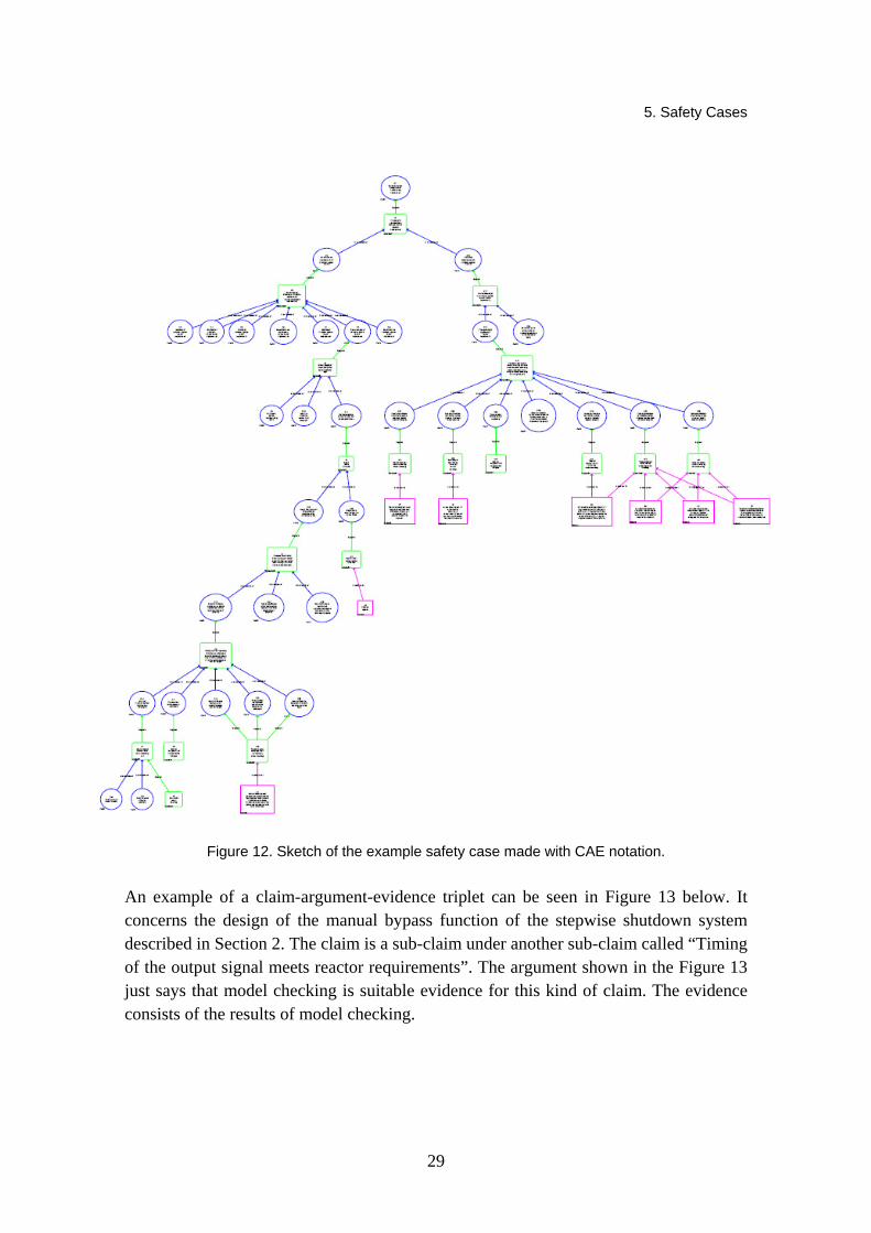
The structure of the example safety case can be seen in Figure 12 below. The blue circles are claims, the green rectangles with round corners are arguments and the red rectangles are evidence. The example safety case is still far from a complete safety case because only the claims that could be shown to be true with model checking were considered. To make the safety case complete would require complementing all the blue leaves with (possibly several levels of) more detailed sub-claims, argumentation and finally evidence.
5. Safety Cases
29
Figure 12. Sketch of the example safety case made with CAE notation.
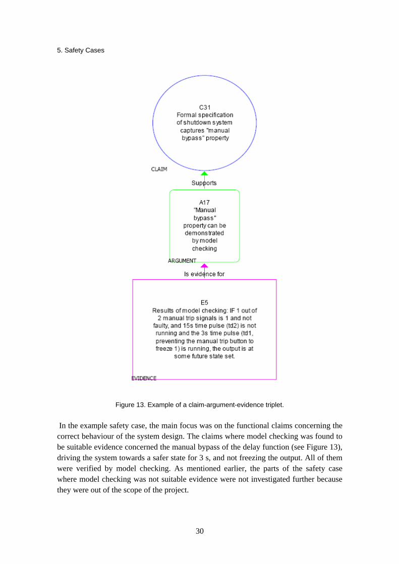
An example of a claim-argument-evidence triplet can be seen in Figure 13 below. It concerns the design of the manual bypass function of the stepwise shutdown system described in Section 2. The claim is a sub-claim under another sub-claim called “Timing of the output signal meets reactor requirements”. The argument shown in the Figure 13 just says that model checking is suitable evidence for this kind of claim. The evidence consists of the results of model checking.
5. Safety Cases
30
Figure 13. Example of a claim-argument-evidence triplet.
In the example safety case, the main focus was on the functional claims concerning the correct behaviour of the system design. The claims where model checking was found to be suitable evidence concerned the manual bypass of the delay function (see Figure 13), driving the system towards a safer state for 3 s, and not freezing the output. All of them were verified by model checking. As mentioned earlier, the parts of the safety case where model checking was not suitable evidence were not investigated further because they were out of the scope of the project.
5. Safety Cases
31
One way to utilize the safety case notation could be using it only for documenting the results of model checking. The verifiable requirements can be written as claims, their justification and additional information can be written under argument and the results of model checking can be documented as evidence. In addition, safety case entities can be colour coded showing the confidence levels of evidence or the success of model checking. Such a structured and visually rich way of documenting the model checking results could be beneficial when the system (e.g. requirements or design) is changed and its behaviour has to be verified again. The tests that failed or passed are easy to spot from a colour-coded tree structure. The safety case styled way of documenting could then be used to support the safety cases aiming at complete safety demonstration.
6. Conclusions
32
6. Conclusions
Digitalized I&C systems are able to perform increasingly more complicated control tasks. They often combine real-time aspects such as timers with non-trivial control logic, making their design and validation very challenging. Model checking is a promising formal method that enables complete verification of designs of such systems. It requires a state machine model of the design and its relevant environment and seems to suit well the verification of safety logic designs.
In the MODSAFE project, the use of two types of model checking approaches was studied to verify safety logic designs involving timing aspects. One approach was to use timed automata as the modelling framework and the other to employ finite state machines typically used in verifying hardware. For the former approach, the UPPAAL model checking system was used and for the latter NuSMV. The approaches were compared using two similar designs of a safety logic demonstrating how small subtle changes in the design can lead to unexpected errors that are hard to detect without using model checking techniques. A straightforward approach to modelling such designs was developed using timed automata and finite state machines and the performance of the model checking tools when verifying the safety requirements of the designs was studied.
UPPAAL supports direct modelling of timers using real-valued clock variables in timed automata so that also the control logic is easy to capture. However, the analysis techniques in UPPAAL are based on state space enumeration techniques which have scaling problems when the number of input variables in the model grows. NuSMV lends itself well to handling control logic but modelling time-dependent components is less straightforward as such components need to be modelled operating in discrete time steps. However, the symbolic model checking techniques used in NuSMV scale much better as the number of input variables grows. Both approaches are able to verify moderate size designs, indicating that current model checking techniques are already applicable to verifying involved safety logic designs. In addition to verifying the correct behaviour of the design, NuSMV was successfully used to analyse whether single failure criteria based on different fault models are satisfied. The results strongly suggest
6. Conclusions
33
that model checking has the potential to become a valuable tool that can be used both in the design and licensing of safety automation.
In addition to modelling and model checking the stepwise shutdown logic, two safety case notations, CAE and GSN, were compared in the project. The main differences between the notations were found to be the number of available entity types that affect the amount of narrative needed to explain the safety case, and that CAE uses a bottom–up approach while GSN is top–down.
The CAE notation was used to make an exploratory safety case concerning the design of the stepwise shutdown system. Only the branches where model checking could be used as evidence were investigated in the project. The other branches were left on a rough level just to outline the structure of a more complete safety case. The safety case notations could be used just for documenting the results of model checking, thus offering a visually rich and reusable way of reporting.
References
34
Acknowledgements
The authors gratefully acknowledge Robin E. Bloomfield and Dan Sheridan from Adelard LLP for their valuable support in developing the safety cases.
References
35
References 1. ASCAD – Adelard Safety Case Development Manual, 1998. ISBN 0 9533771 0 5.
2. ASCE tool, Assurance and safety case environment, Accessed 4.2.2009. http://www.adelard.com/web/hnav/ASCE/index.html.
3. Alur, R., Courcoubetis, C. and Dill, D. “Model-checking for real-time systems”. In: Proceedings, Fifth Annual IEEE Symposium on Logic in Computer Science, 1990. Pp. 414–425.
4. Alur, R. and Dill, D.L. “A theory of timed automata”. Theoretical Computer Science, 126(2): (1994), pp.183–235.
5. Biere, A., Cimatti, A., Clarke, E.M. and Zhu, Y. “Symbolic model checking without BDDs”. In: Proc. of the Fifth International Conference on Tools and Algorithms for the Construction and Analysis of Systems (TACAS’99), (1999).
6. Biere, A., Heljanko, K., Junttila, T., Latvala, T. and Schuppan, V. “Linear Encodings of Bounded LTL Model Checking”. Logical Methods in Computer Science 2(5:5): 2006, pp. 1–64.
7. Bishop, P.G. and Bloomfield, R.E. “A methodology for safety case development”, In: Safety-Critical Systems Symposium (SSS ’98), Birmingham, UK, February 1998.
8. Björkman, K., Frits, J., Valkonen, J., Lahtinen, J., Heljanko, K., Niemelä, I. and Hämäläinen, J.J. “Verification of Safety Logic Designs by Model Checking”. Sixth American Nuclear Society International Topical Meeting on Nuclear Plant Instrumentation, Control, and Human-Machine Interface Technologies, NPIC&HMIT 2009, Knoxville, Tennessee, April 5–9, 2009, on CD-ROM, American Nuclear Society, LaGrange Park, IL 2009.
9. Bryant, R.E. “Graph-Based Algorithms for Boolean Function Manipulation”. IEEE Trans. Computers 35(8): 1986, pp. 677–691.
10. Cavada, R., Cimatti, A., Jochim, C.A., Keighren, G., Olivetti, E., Pistore, M., Roveri, M. and Tchaltsev, A. “NuSMV 2.4 User Manual”, CMU and ITC-irst (2005).
11. Clarke, E.M., Grumberg, O. and Peled, D.A. “Model Checking”, The MIT Press, 1999.
References
36
12. Clarke, E.M. and Emerson, E.A. “Design and synthesis of synchronization of skeletons using branching time temporal logic”. In: Proceedings of the IBM Workshop on Logics of Programs, Vol. 131 of LNCS, Springer, 1981. Pp. 52–71.
13. IAEA International Atomic Energy Agency, Vienna. IAEA Safety Glossary: Terminology Used in Nuclear Safety and Radiation Protection, 2007.
14. Larsen, K.G., Pettersson, P. and Yi, W. “UPPAAL in a nutshell”. International Journal on Software Tools for Technology Transfer, 1(1–2): 1997, pp. 134–152.
15. McMillan, K.L. “Symbolic Model Checking”, Kluwer Academic Publ., (1993).
16. NuSMV Model Checker v.2.4.3, 2008. Available from http://nusmv.irst.itc.it/.
17. Quielle, J. and Sifakis, J. “Specification and verification of concurrent systems in CESAR”. In: Proceedings of the 5th International Symposium on Programming, 1981. Pp. 337–350.
18. UPPAAL integrated tool environment v. 4.0.6, http://www.uppaal.com/ (2009).
19. Valkonen, J., Karanta, I., Koskimies, M., Heljanko, K., Niemelä, I., Sheridan, D. and Bloomfield, R.E. “NPP Safety Automation Systems Analysis – State of the Art”. VTT Working Papers 94, VTT, Espoo, 2008. 62 p. http://www.vtt.fi/inf/pdf/workingpapers/2008/W94.pdf.
20. Valkonen, J., Pettersson, V., Björkman, K., Holmberg, J.-E., Koskimies, M., Heljanko, K. and Niemelä, I. “Model-Based Analysis of an Arc Protection and an Emergency Cooling System – MODSAFE 2007 Working Report”. VTT Working Papers 93, VTT, Espoo, 2008. 13 p. + app. 38 p. http://www.vtt.fi/inf/pdf/workingpapers/2008/W93.pdf.
A1
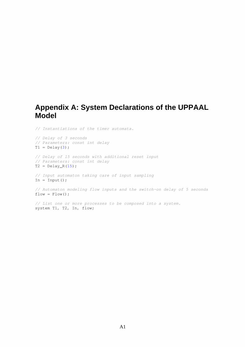
Appendix A: System Declarations of the UPPAAL Model // Instantiations of the timer automata. // Delay of 3 seconds // Parameters: const int delay T1 = Delay(3); // Delay of 15 seconds with additional reset input // Parameters: const int delay T2 = Delay_R(15); // Input automaton taking care of input sampling In = Input(); // Automaton modeling flow inputs and the switch-on delay of 5 seconds flow = Flow(); // List one or more processes to be composed into a system. system T1, T2, In, flow;

B1
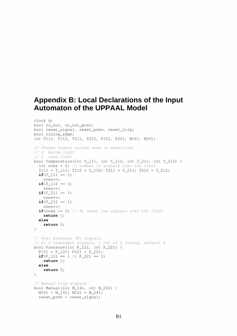
Appendix B: Local Declarations of the Input Automaton of the UPPAAL Model clock d; bool or_out, or_out_prev; bool reset_signal, reset_prev, reset_trig; bool rising_edge; int T111, T112, T211, T212, P121, P221, M141, M241; // Chosen signal values used in modelling: // 0 below limit // 1 over limit bool Temperature(int T_111, int T_112, int T_211, int T_212) { int ones = 0; // number of signals over the limit T111 = T_111; T112 = T_112; T211 = T_211; T212 = T_212; if(T_111 == 1) ones++; if(T_112 == 1) ones++; if(T_211 == 1) ones++; if(T_212 == 1) ones++; if(ones >= 2) // At least two signals over the limit return 1; else return 0; } // Over pressure (P) signals // P: 2 redundant signals, 1 out of 2 voting, default 0 bool Pressure(int P_121, int P_221) { P121 = P_121; P221 = P_221; if(P_121 == 1 || P_221 == 1) return 1; else return 0; } // Manual trip signals bool Manual(int M_141, int M_241) { M141 = M_141; M241 = M_241; reset_prev = reset_signal;
Appendix B: Local Declarations of the Input Automaton of the UPPAAL Model
B2
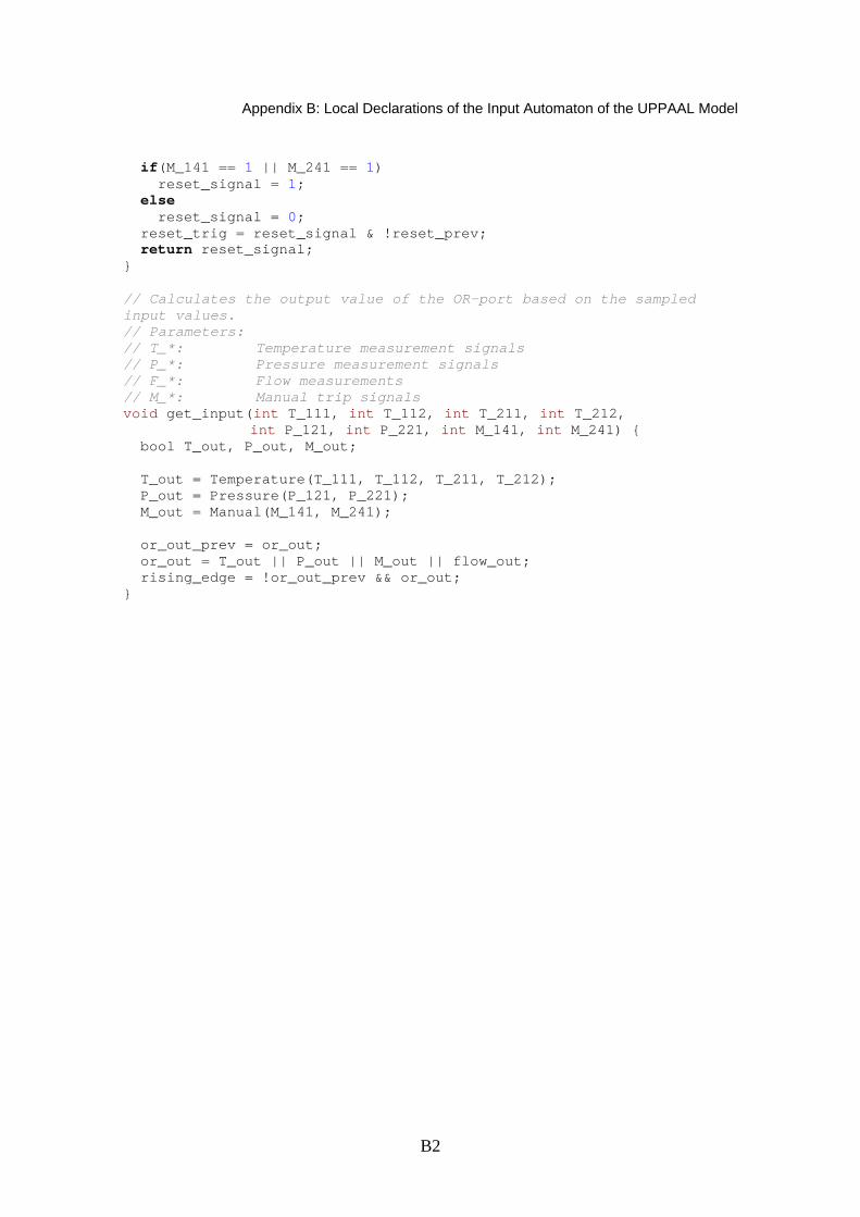
if(M_141 == 1 || M_241 == 1) reset_signal = 1; else reset_signal = 0; reset_trig = reset_signal & !reset_prev; return reset_signal; } // Calculates the output value of the OR-port based on the sampled input values. // Parameters: // T_*: Temperature measurement signals // P_*: Pressure measurement signals // F_*: Flow measurements // M_*: Manual trip signals void get_input(int T_111, int T_112, int T_211, int T_212, int P_121, int P_221, int M_141, int M_241) { bool T_out, P_out, M_out; T_out = Temperature(T_111, T_112, T_211, T_212); P_out = Pressure(P_121, P_221); M_out = Manual(M_141, M_241); or_out_prev = or_out; or_out = T_out || P_out || M_out || flow_out; rising_edge = !or_out_prev && or_out; }
VTT WORKING PAPERS 115VTT CREATES BUSINESS FROM TECHNOLOGY�Technology�and�market�foresight�•�Strategic�research�•�Product�and�service�development�•�IPR�and�licensing�•�Assessments,�testing,�inspection,�certification�•�Technology�and�innovation�management�•�Technology�partnership
•�•�•��VTT�WO
RKIN
G�PA
PERS�115�����M
OD
EL-BA
SED�A
NA
LYSIS�OF�A
�STEPWISE�SH
UTD
OW
N�LO
GIC
.�MO
DSA
FE�2008�WO
RK�R
EPOR
T
ISBN 978-951-38-7176-5 (URL: http://www.vtt.fi/publications/index.jsp) ISSN 1459-7683 (URL: http://www.vtt.fi/publications/index.jsp)
Kim Björkman1, Juho Frits2, Janne Valkonen1, Keijo Heljanko2 & Ilkka Niemelä2
Model-Based Analysis of a Stepwise Shutdown Logic
MODSAFE 2008 Work Report
1VTT Technical Research Centre of Finland2Helsinki University of Tehcnology TKK Department of Information and Computer Science