Mobilné dátové sietefiles.gamepub.sk/statnice/KP/KP/z ktl stranky/prednasky/Mobilne dat… ·...
44
Mobilné dátové siete GSM/GPRS/EDGE/UMTS & more
Transcript of Mobilné dátové sietefiles.gamepub.sk/statnice/KP/KP/z ktl stranky/prednasky/Mobilne dat… ·...
Mobilné dátové siete
GSM/GPRS/EDGE/UMTS&
more
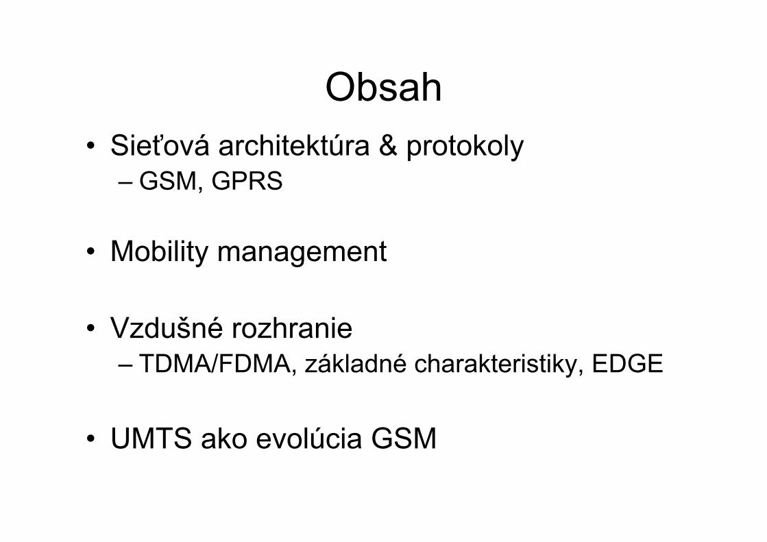
Obsah• Sieťová architektúra & protokoly
– GSM, GPRS
• Mobility management
• Vzdušné rozhranie– TDMA/FDMA, základné charakteristiky, EDGE
• UMTS ako evolúcia GSM

architektúra GSM
BSC
BTS
bunka
MSC
HLR
VLR AuC EIR
GMSC PSTN
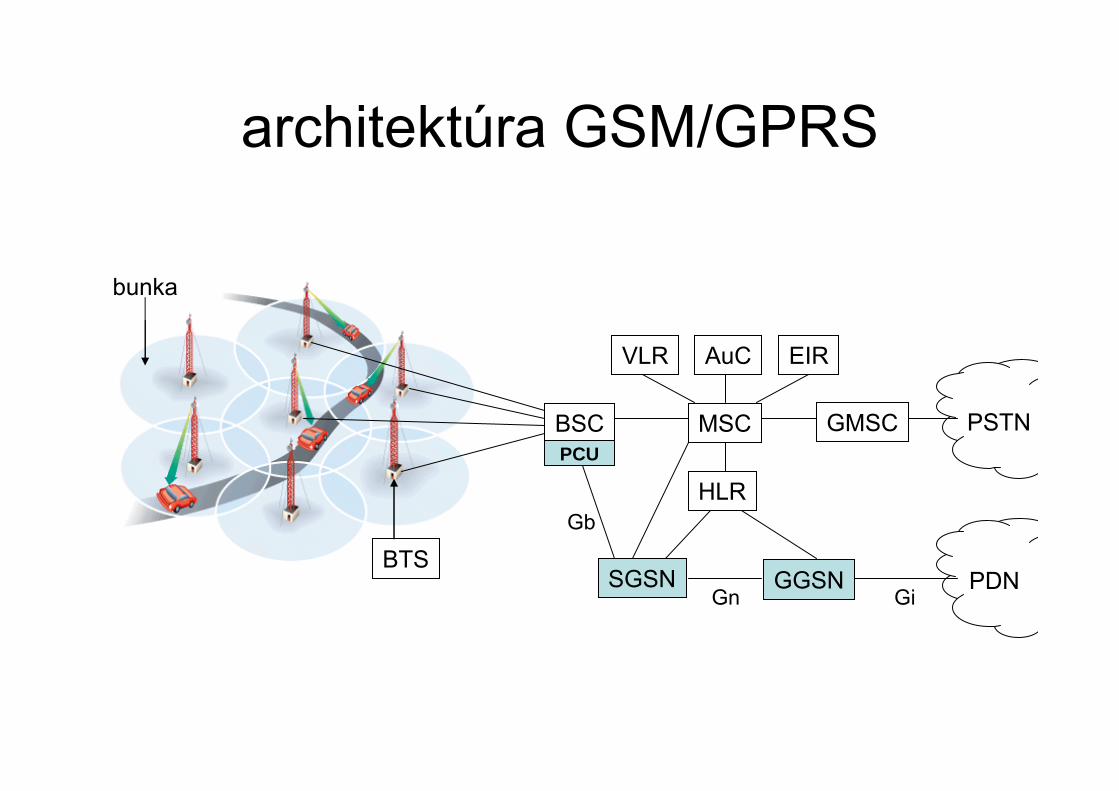
architektúra GSM/GPRS
BSC
BTS
bunka
MSC
HLR
VLR AuC EIR
GMSC PSTNPCU
SGSN GGSN PDN
Gb
Gn Gi
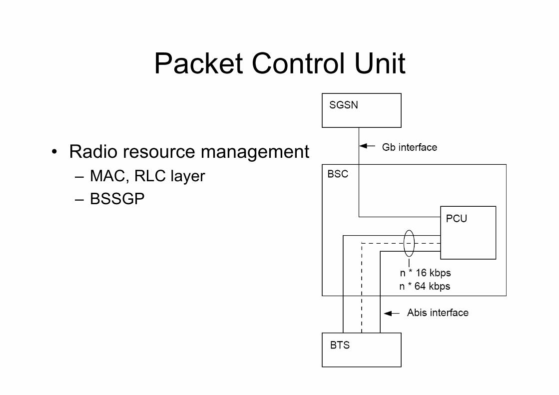
Packet Control Unit
• Radio resource management– MAC, RLC layer– BSSGP

Serving GPRS Support Node
Main functions:– charging– IP connectivity & routing– mobility management– payload handling– QoS– security– session management– subscriber data management
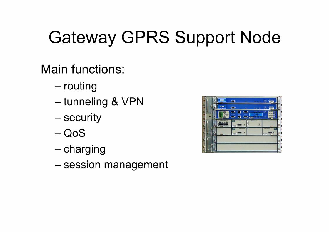
Gateway GPRS Support Node
Main functions:– routing– tunneling & VPN– security– QoS– charging– session management
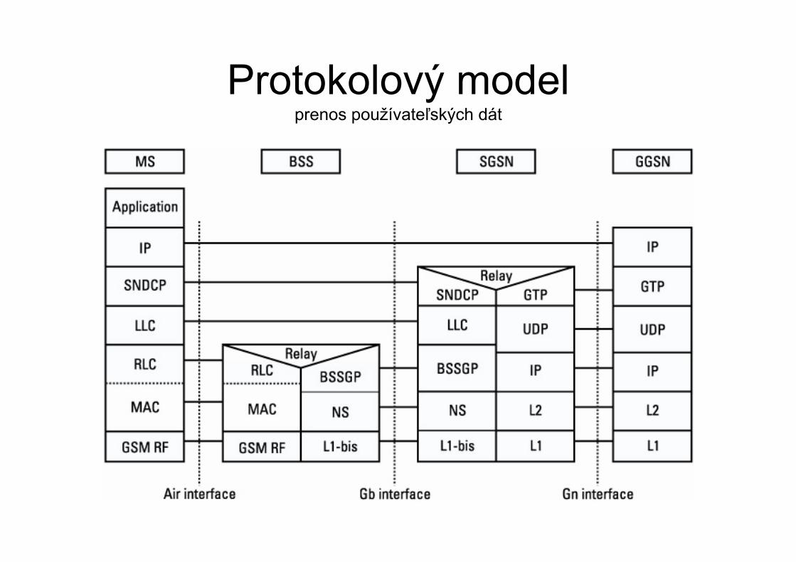
Protokolový model prenos používateľských dát
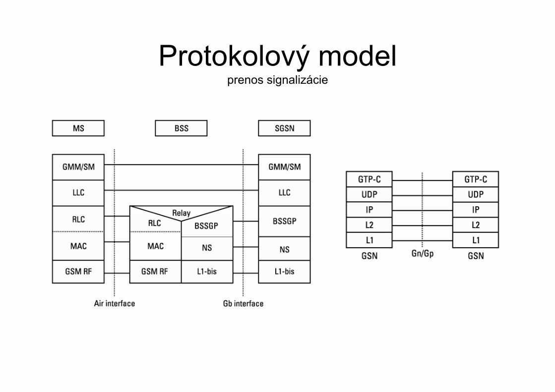
Protokolový model prenos signalizácie
GTP
• used on Gn interface (SGSN-GGSN)• IP based connection (backbone)• GTP-U for user data• GTP-C for control
– create, update, and delete tunnels– path/mobility/location management,
• point-to-point UDP/IP tunnel
SNDCP
• on Gb interface• multiplexing of PDPs (NSAPI)• compression of user data (including IP
header compression)• segmentation/reassembly of data packets
to be passed to/from the LLC layer
LLC
• provides a reliable link between the mobile device and the SGSN for both control and user data
• supports variable length information fields from 140 bytes up to a max of 1520 bytes
• acknowledged/unacknowledged mode
BSSGP
• introduce & provide the required QoS for the user
• routing information between BSS & SGSN• informs the BSC about the radio capability
of the mobile device• flow control
Session/Mobility management
• Routing area concept
• Session management – PDP context
• Mobility states– attach/detach procedure
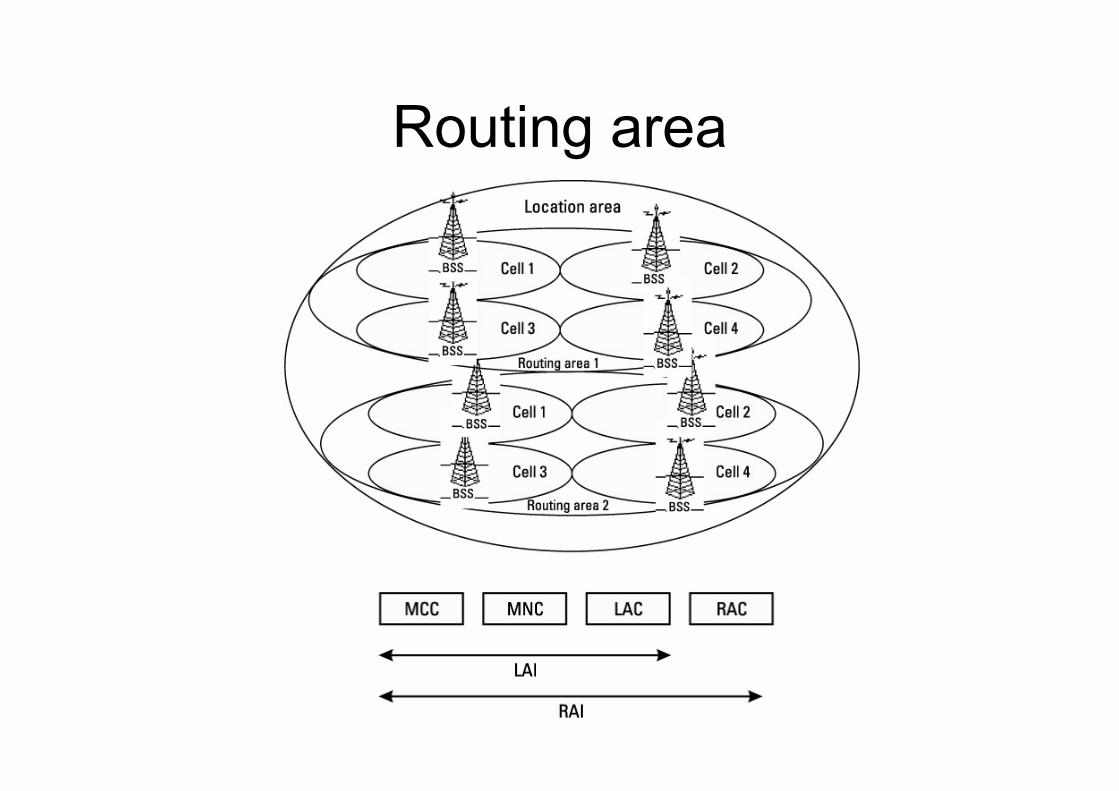
Routing area
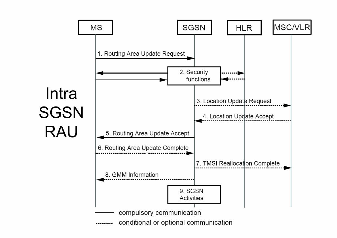
Intra SGSN RAU
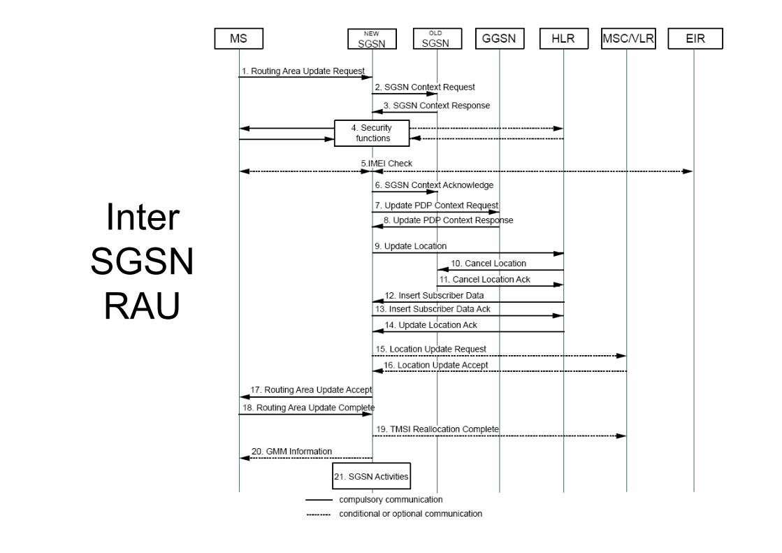
Inter SGSN RAU
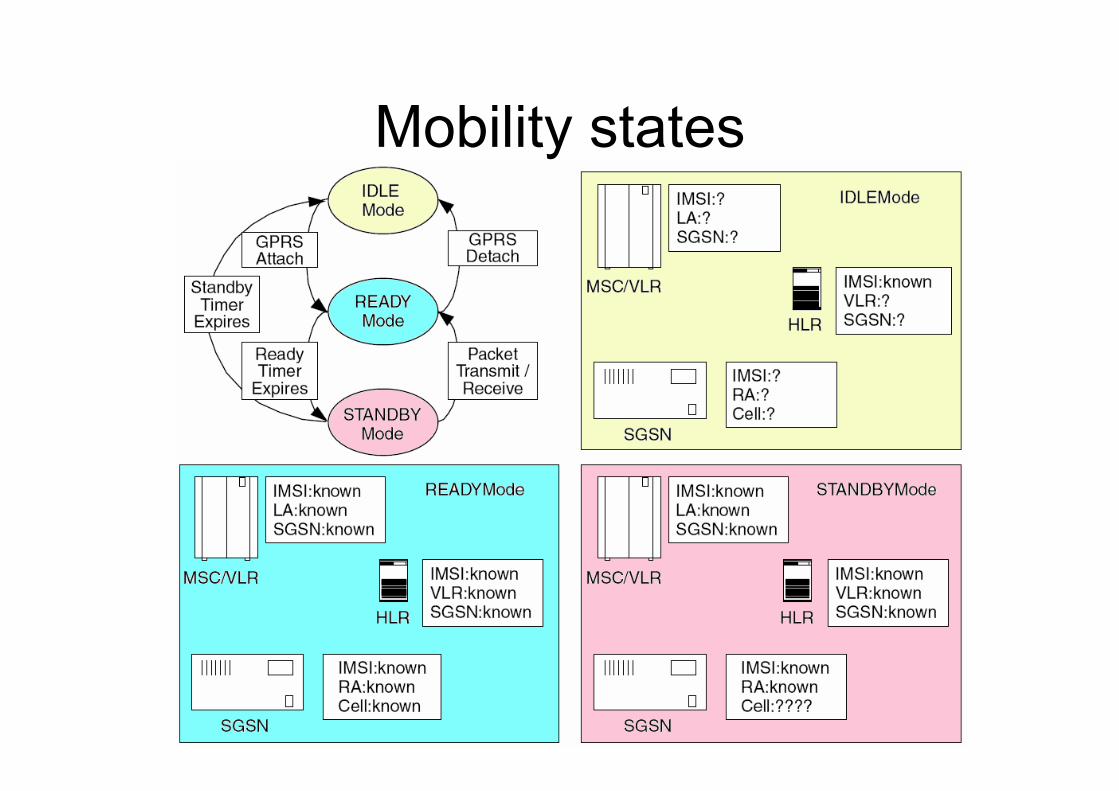
Mobility states
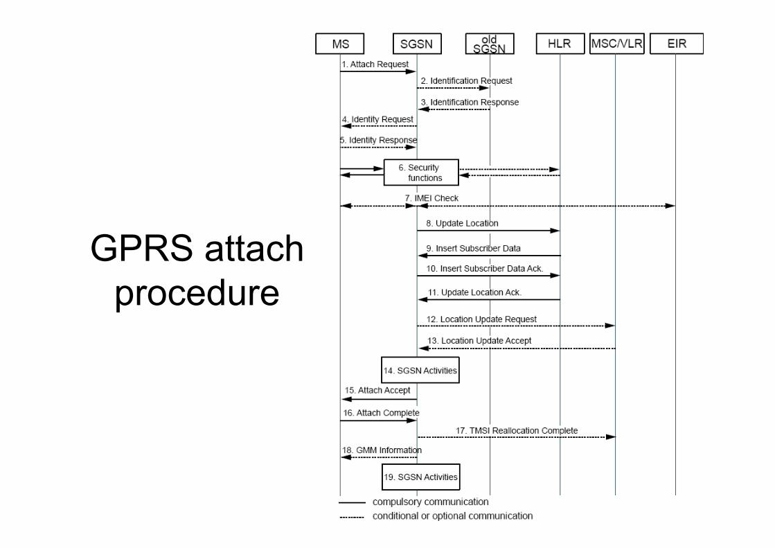
GPRS attach procedure
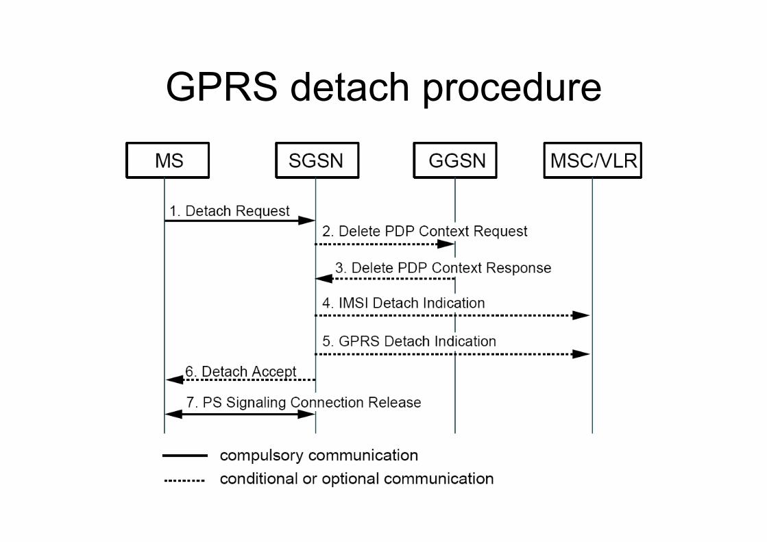
GPRS detach procedure
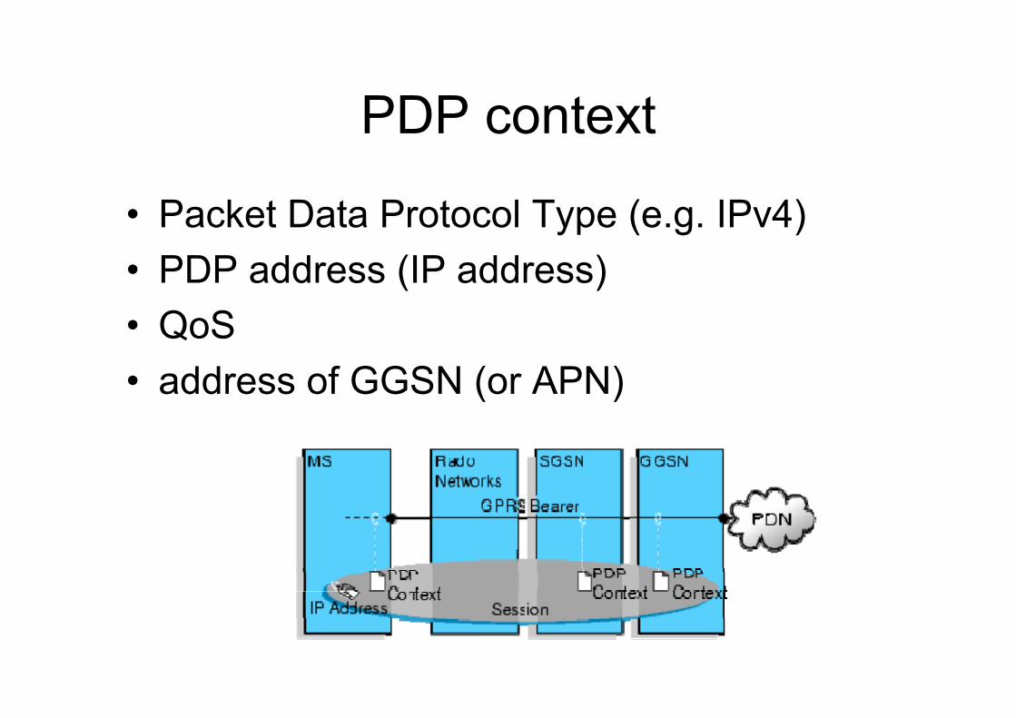
PDP context
• Packet Data Protocol Type (e.g. IPv4)• PDP address (IP address)• QoS• address of GGSN (or APN)
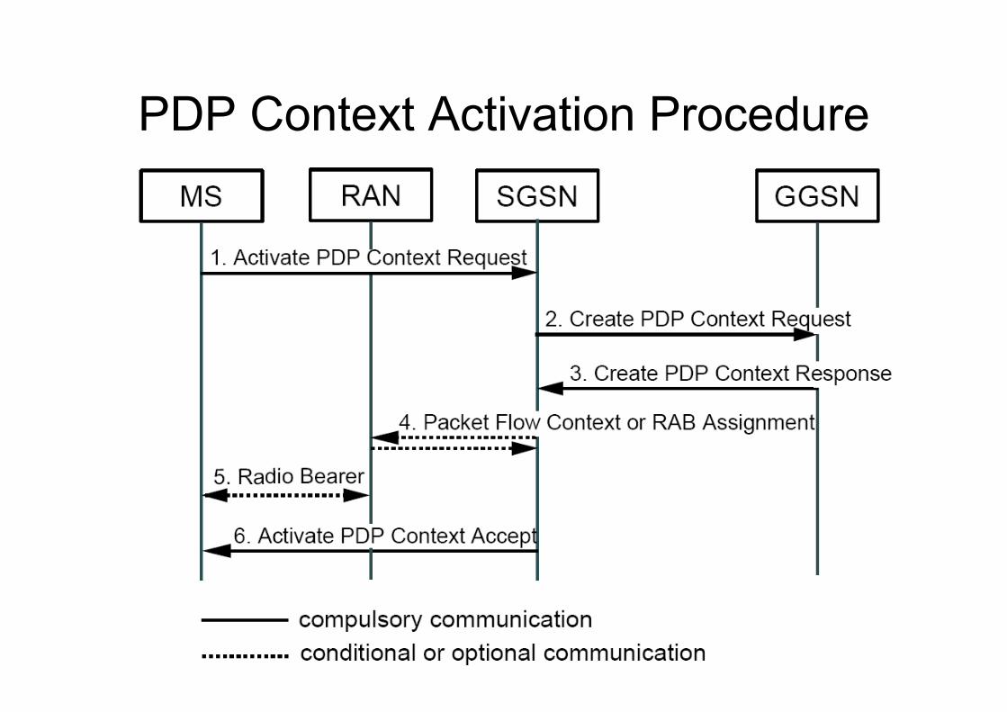
PDP Context Activation Procedure
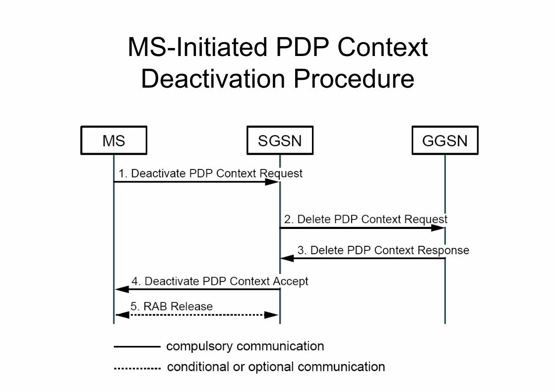
MS-Initiated PDP Context Deactivation Procedure
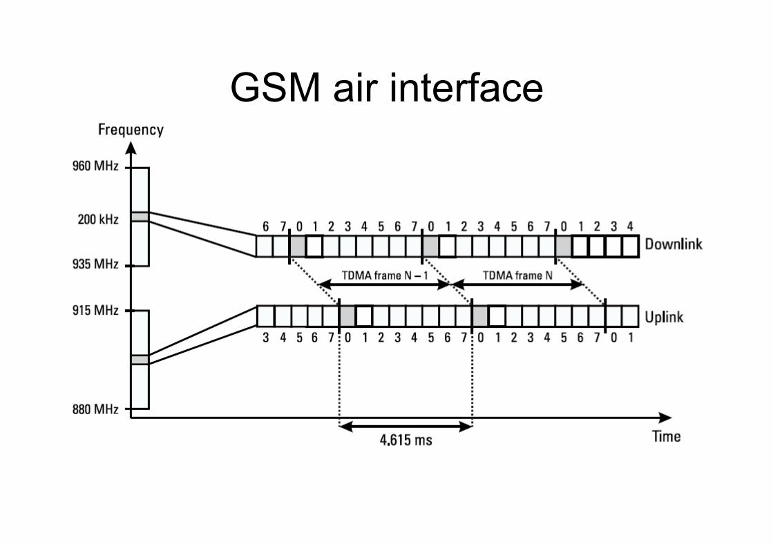
GSM air interface
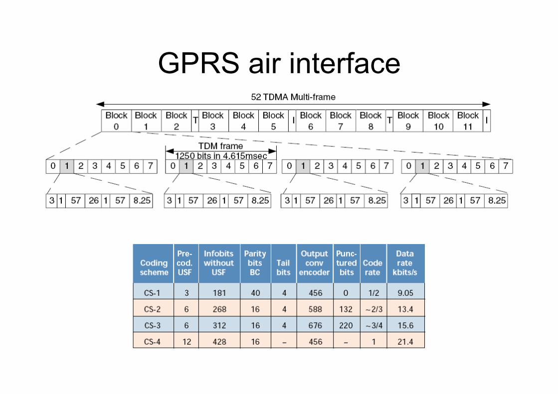
GPRS air interface
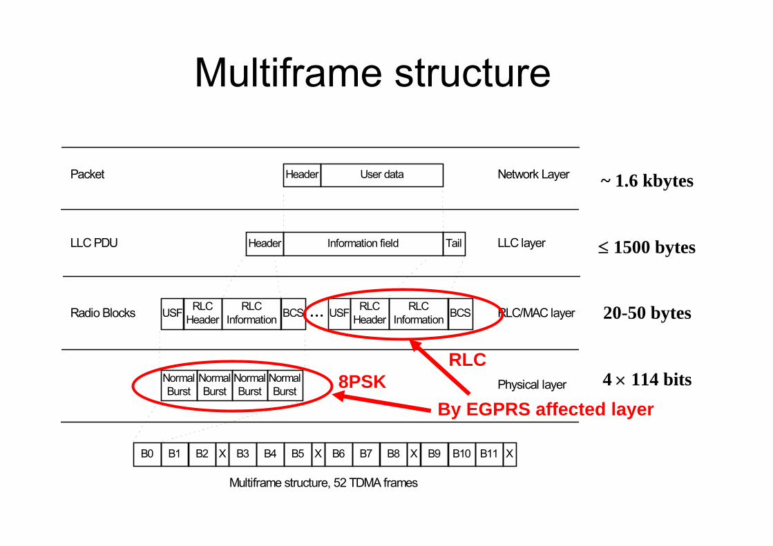
Packet Header User data
Information field TailHeaderLLC PDU
USF RLCHeader
RLCInformation BCS ...Radio Blocks
LLC layer
RLC/MAC layer
Physical layer
Multiframe structure, 52 TDMA frames
Network Layer
USF RLCHeader
RLCInformation BCS
NormalBurst
NormalBurst
NormalBurst
NormalBurst
B0 B1 B2 X B3 B4 B5 X B6 B7 B8 X B9 B10 B11 X
~ 1.6 kbytes
≤ 1500 bytes
20-50 bytes
4 × 114 bitsBy EGPRS affected layer
RLC8PSK
Multiframe structure
10
20
30
40
50
60
0
MC
S1
MC
S2
MC
S3
MC
S4
MC
S5
MC
S6
MC
S7
MC
S8
MC
S9
CS1
CS2
CS3
CS4
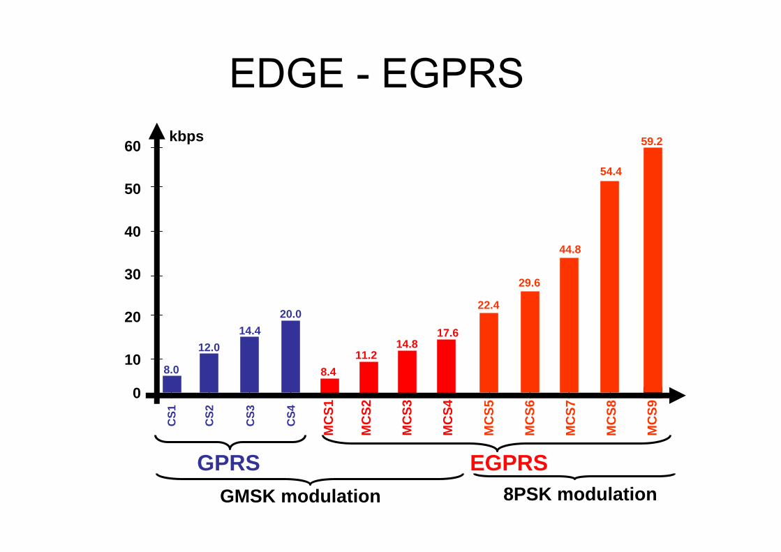
GMSK modulation 8PSK modulation
8.0
12.014.4
20.0
8.411.2
14.817.6
22.4
29.6
44.8
54.4
59.2kbps
GPRS EGPRS
EDGE - EGPRS
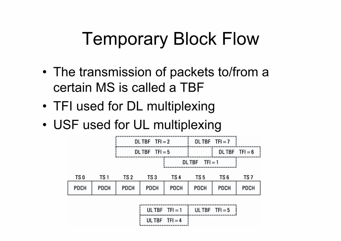
Temporary Block Flow
• The transmission of packets to/from a certain MS is called a TBF
• TFI used for DL multiplexing• USF used for UL multiplexing
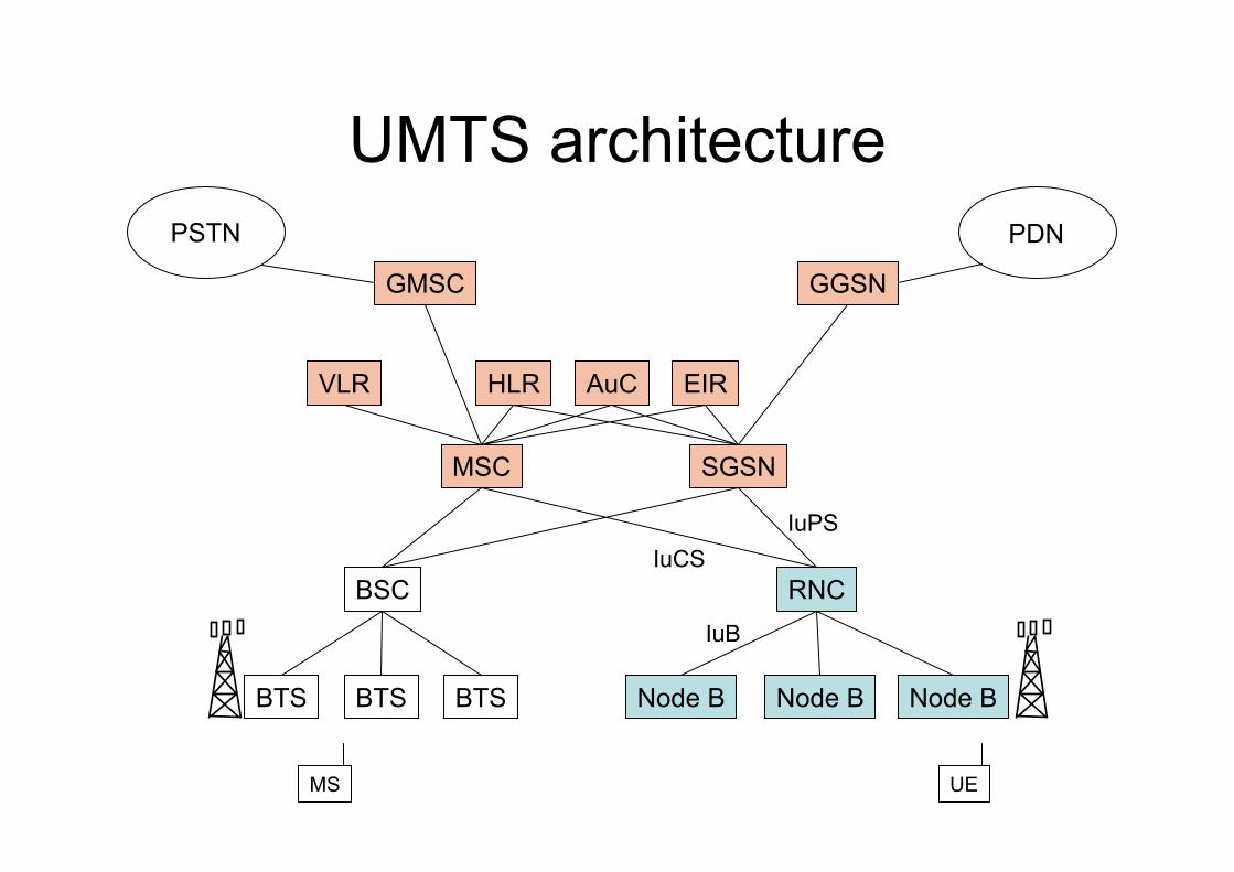
UMTS architecture
BSC
BTSBTSBTS
RNC
Node B Node B Node B
MSC SGSN
GGSNGMSC
VLR HLR AuC EIR
PSTN PDN
MS UE
IuB
IuCSIuPS
Basic facts
• new radio access technology– CDMA, 5 MHz FDD, …
• smooth evolution of core network
• new protocol stacks for new interfaces
• some changes in mobility management
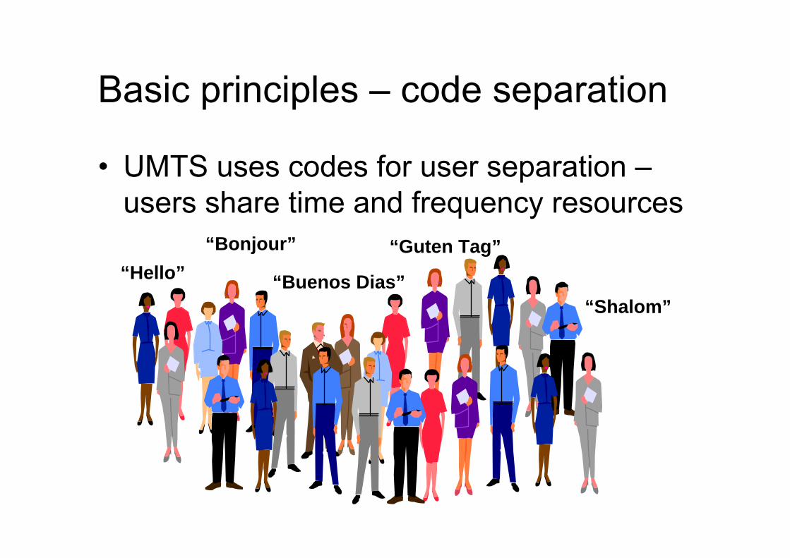
Basic principles – code separation
• UMTS uses codes for user separation –users share time and frequency resources
“Hello”“Bonjour”
“Shalom”“Buenos Dias”
“Guten Tag”
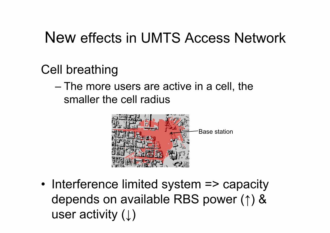
Base station
New effects in UMTS Access Network
Cell breathing– The more users are active in a cell, the
smaller the cell radius
• Interference limited system => capacity depends on available RBS power (↑) & user activity (↓)
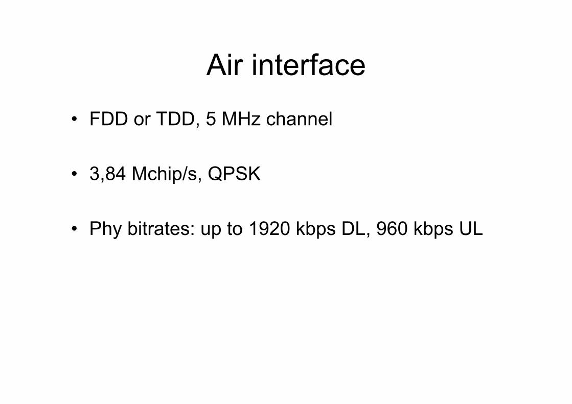
Air interface
• FDD or TDD, 5 MHz channel
• 3,84 Mchip/s, QPSK
• Phy bitrates: up to 1920 kbps DL, 960 kbps UL
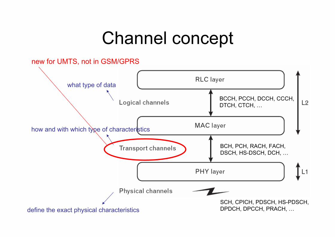
Channel concept
what type of data
how and with which type of characteristics
define the exact physical characteristics
BCCH, PCCH, DCCH, CCCH,DTCH, CTCH, …
BCH, PCH, RACH, FACH,DSCH, HS-DSCH, DCH, …
SCH, CPICH, PDSCH, HS-PDSCH,DPDCH, DPCCH, PRACH, …
new for UMTS, not in GSM/GPRS
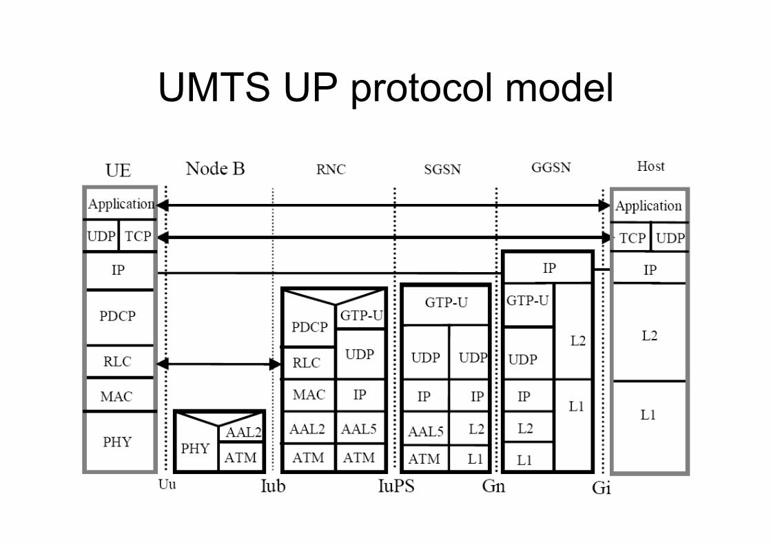
UMTS UP protocol model
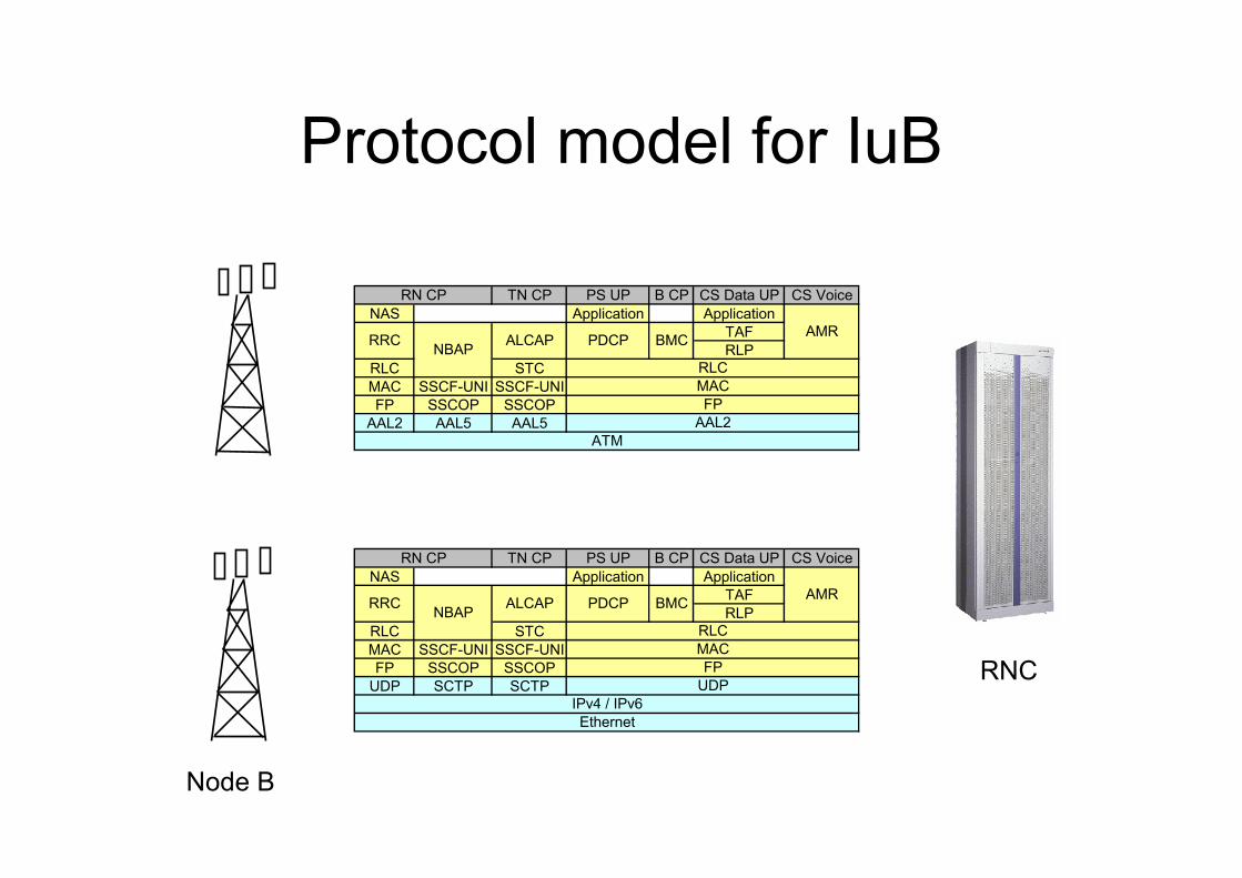
Protocol model for IuB
TN CP PS UP B CP CS Data UP CS VoiceNAS Application Application
TAFRLP
RLC STCMAC SSCF-UNI SSCF-UNIFP SSCOP SSCOP
AAL2 AAL5 AAL5ATM
MACFP
AAL2
AMR
RLC
ALCAP PDCP BMCRRC NBAP
RN CP
TN CP PS UP B CP CS Data UP CS VoiceNAS Application Application
TAFRLP
RLC STCMAC SSCF-UNI SSCF-UNIFP SSCOP SSCOP
UDP SCTP SCTP UDPIPv4 / IPv6Ethernet
RN CP
AMRRRC NBAP ALCAP PDCP BMC
RLCMACFP
Node B
RNC
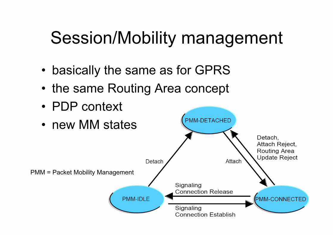
Session/Mobility management
• basically the same as for GPRS• the same Routing Area concept• PDP context• new MM states
PMM = Packet Mobility Management
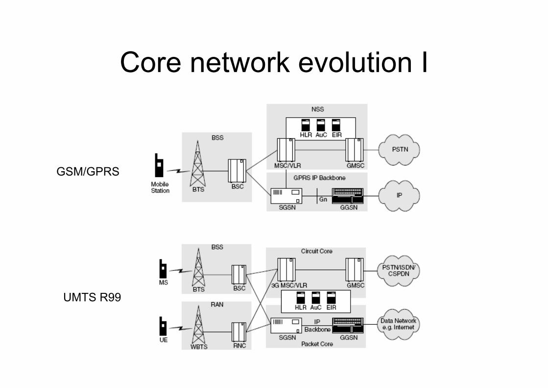
Core network evolution I
GSM/GPRS
UMTS R99
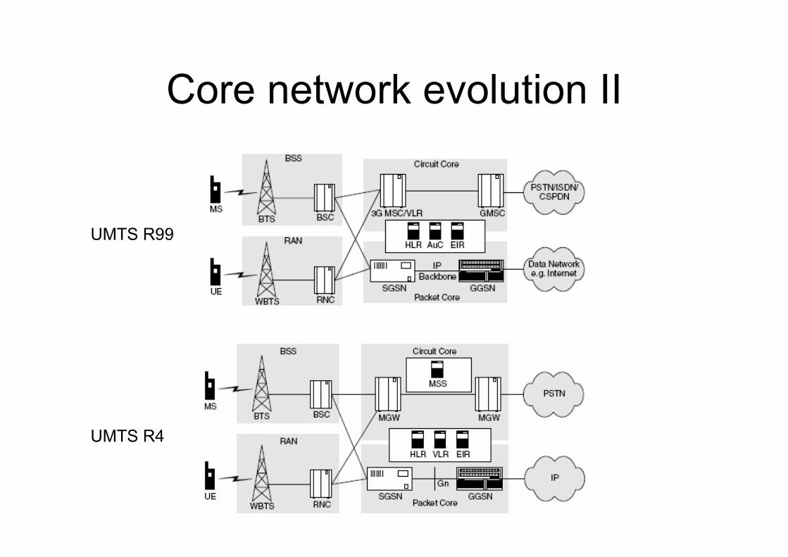
Core network evolution II
UMTS R4
UMTS R99
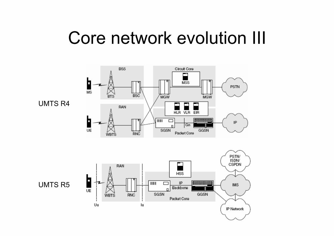
Core network evolution III
UMTS R5
UMTS R4

UMTS System Architecture Evolution
Gb Iu
GERAN UTRAN
3G2GeRAN
LTENon-3GPP
MME/UPE
SGi
IP networks
S3
S4
S5a
S6 S7
S1
S2a
PCRFHSS
SGSN
3GPPAnchor
SAEAnchor
S5b
IASA
IP access WLAN
ePDG
S2b
Non-3GPP
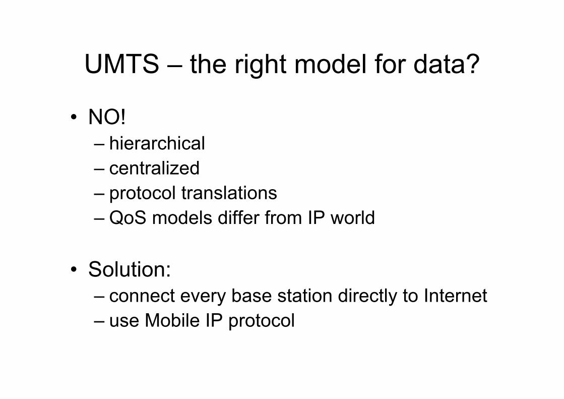
UMTS – the right model for data?
• NO!– hierarchical– centralized– protocol translations– QoS models differ from IP world
• Solution:– connect every base station directly to Internet– use Mobile IP protocol
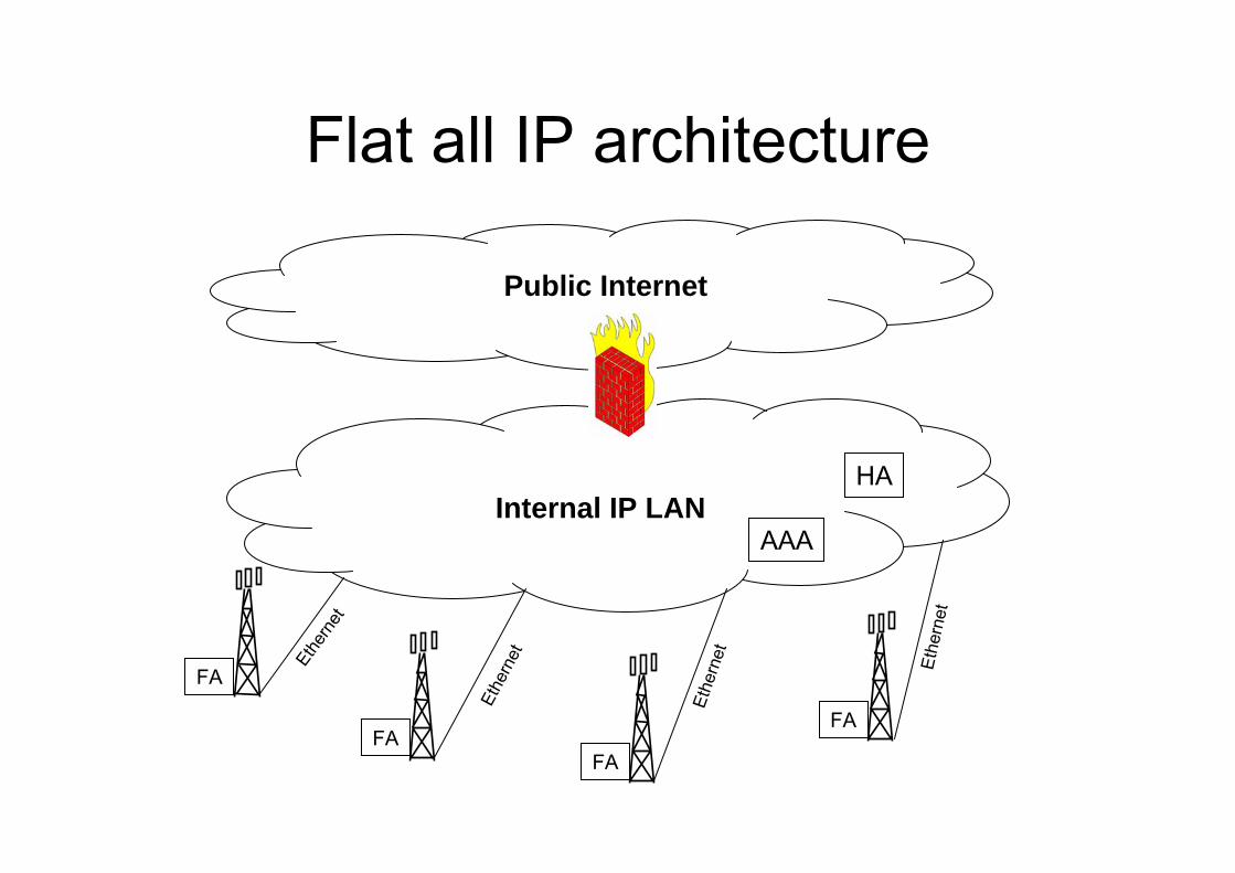
Flat all IP architecture
AAA
HAInternal IP LAN
Public Internet
FA
FAFA
FA
Ethe
rnetEthe
rnet
Ethe
rnet Ethe
rnet
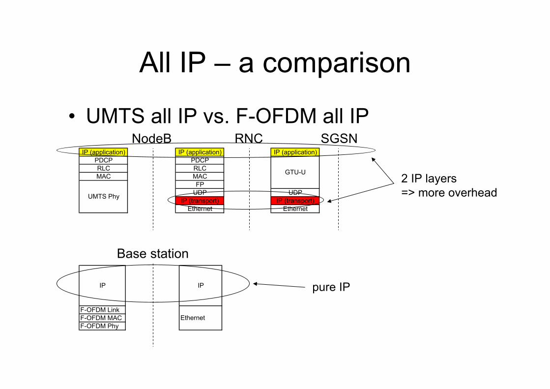
All IP – a comparison
• UMTS all IP vs. F-OFDM all IP
F-OFDM LinkF-OFDM MACF-OFDM Phy
IP IP
Ethernet
Base station
NodeB RNC SGSNIP (application)
PDCPRLCMAC
UMTS Phy
IP (application)PDCPRLCMACFP
UDPIP (transport)
Ethernet
IP (application)
UDPIP (transport)
Ethernet
GTU-U2 IP layers=> more overhead
pure IP