MAYUKH PRESENTATION
19
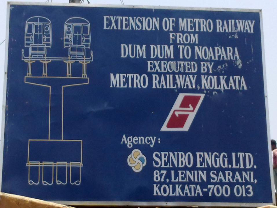
KOLKATA METRO PROJECT, NOAPARA, DUMDUM By Mayukh Bhattacharjee 1221010041, 3 rd year Civil Infrastructure
-
Upload
mayukh-bhattacharjee -
Category
Documents
-
view
92 -
download
0
Transcript of MAYUKH PRESENTATION
KOLKATA
METRO
PROJECT,
NOAPARA,
DUMDUM
By
Mayukh Bhattacharjee
1221010041, 3rd year
Civil Infrastructure
• I sincerely thank SENBO CONSTRUCTIONS for giving me a the opportunity to do my training in their esteemed firm. • Mr. Partha Chakrabharty, Vice- President ( SENBO CONSTRUCTIONS) for assigning me into the training. • Mr. Prantik Bhowmick, Project Manager ( Metro rail constructions,Noapara) for guiding and helping me out with every aspect during my training. • Mr. S. Nanda for his support in making of the project report.
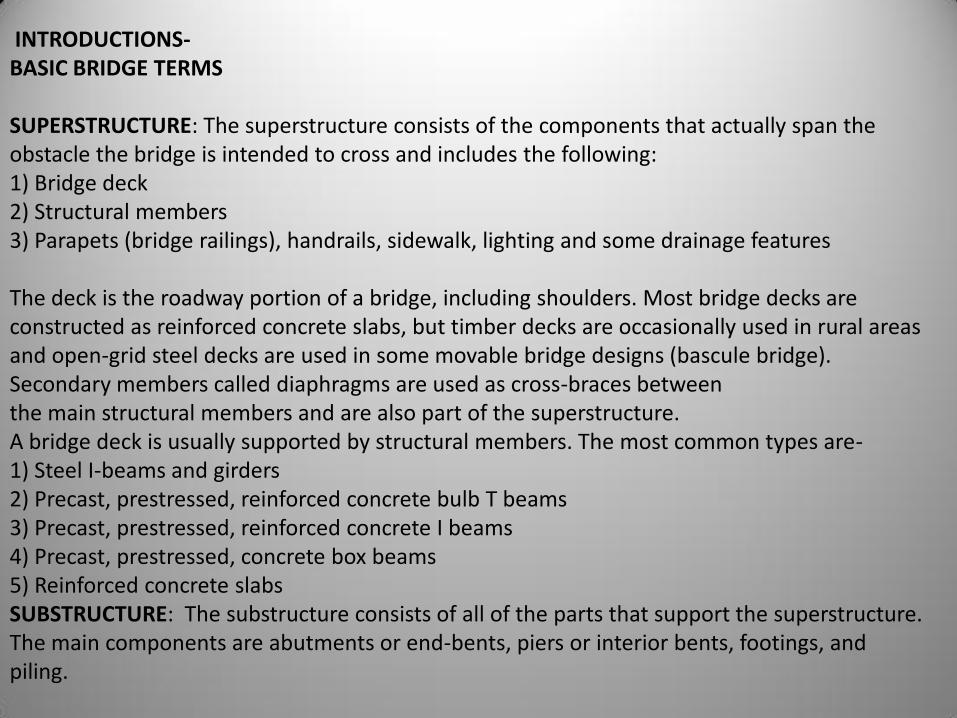
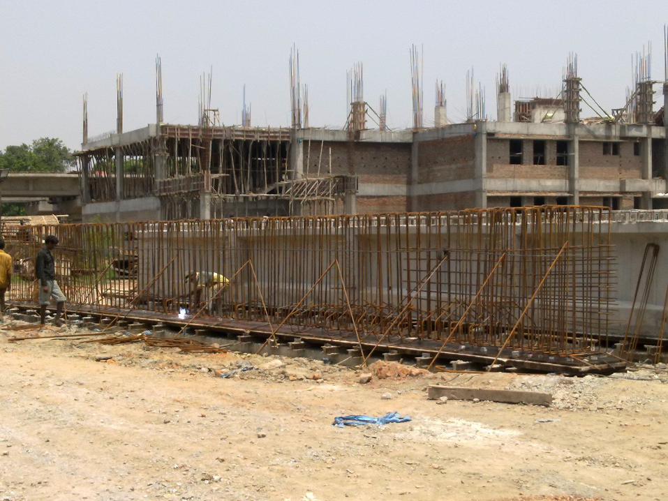
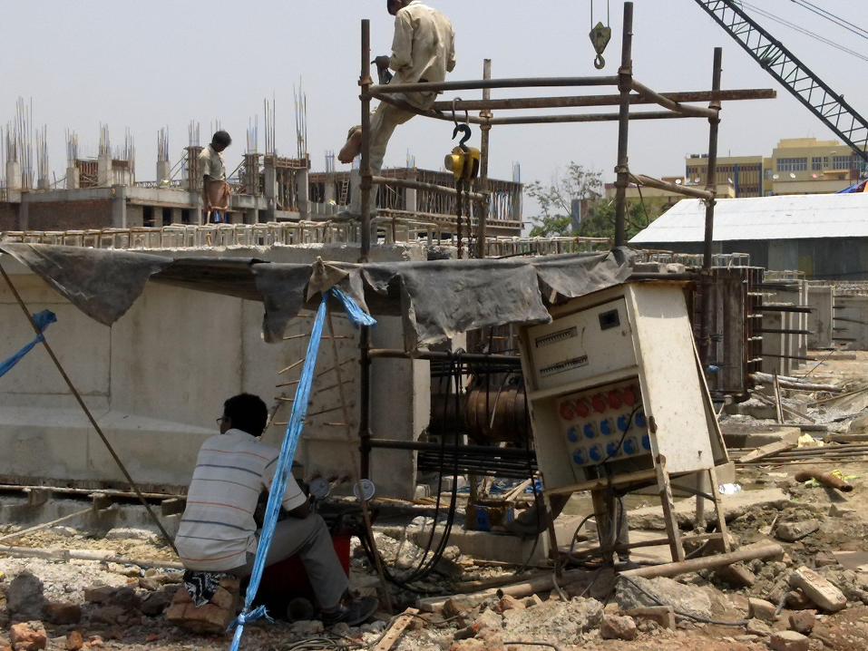
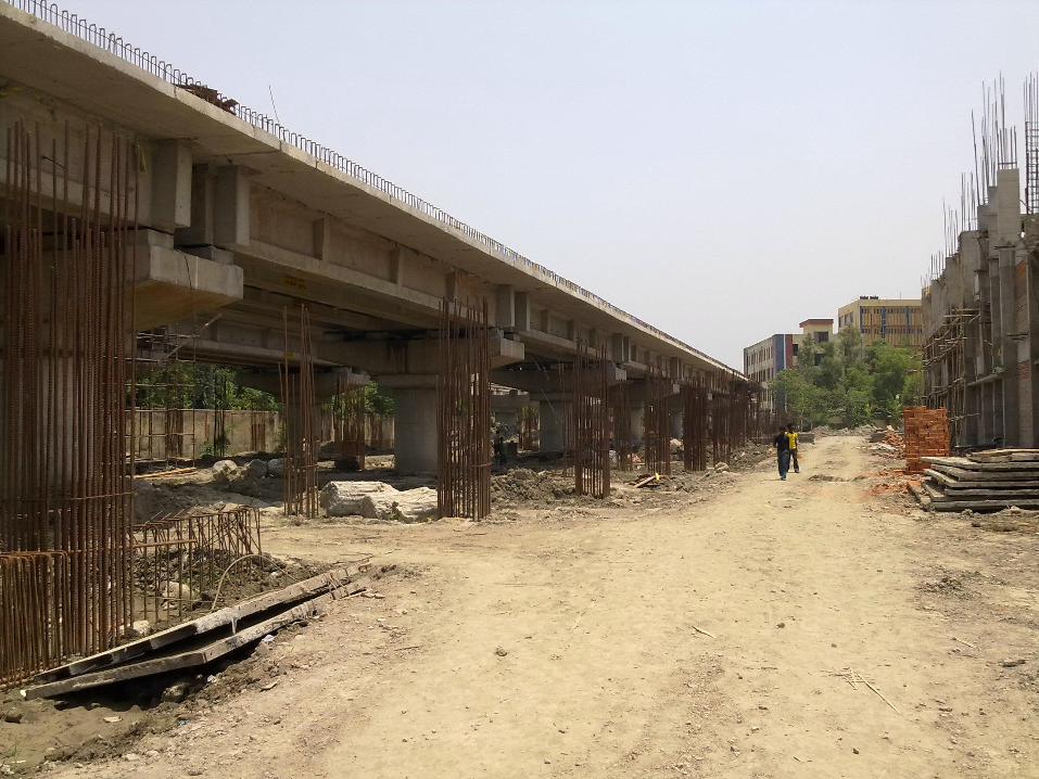
INTRODUCTIONS- BASIC BRIDGE TERMS SUPERSTRUCTURE: The superstructure consists of the components that actually span the obstacle the bridge is intended to cross and includes the following: 1) Bridge deck 2) Structural members 3) Parapets (bridge railings), handrails, sidewalk, lighting and some drainage features The deck is the roadway portion of a bridge, including shoulders. Most bridge decks are constructed as reinforced concrete slabs, but timber decks are occasionally used in rural areas and open-grid steel decks are used in some movable bridge designs (bascule bridge). Secondary members called diaphragms are used as cross-braces between the main structural members and are also part of the superstructure. A bridge deck is usually supported by structural members. The most common types are- 1) Steel I-beams and girders 2) Precast, prestressed, reinforced concrete bulb T beams 3) Precast, prestressed, reinforced concrete I beams 4) Precast, prestressed, concrete box beams 5) Reinforced concrete slabs SUBSTRUCTURE: The substructure consists of all of the parts that support the superstructure. The main components are abutments or end-bents, piers or interior bents, footings, and piling.
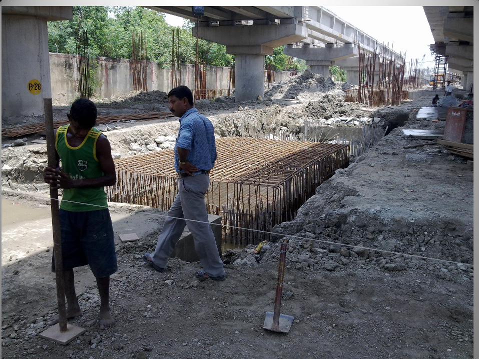
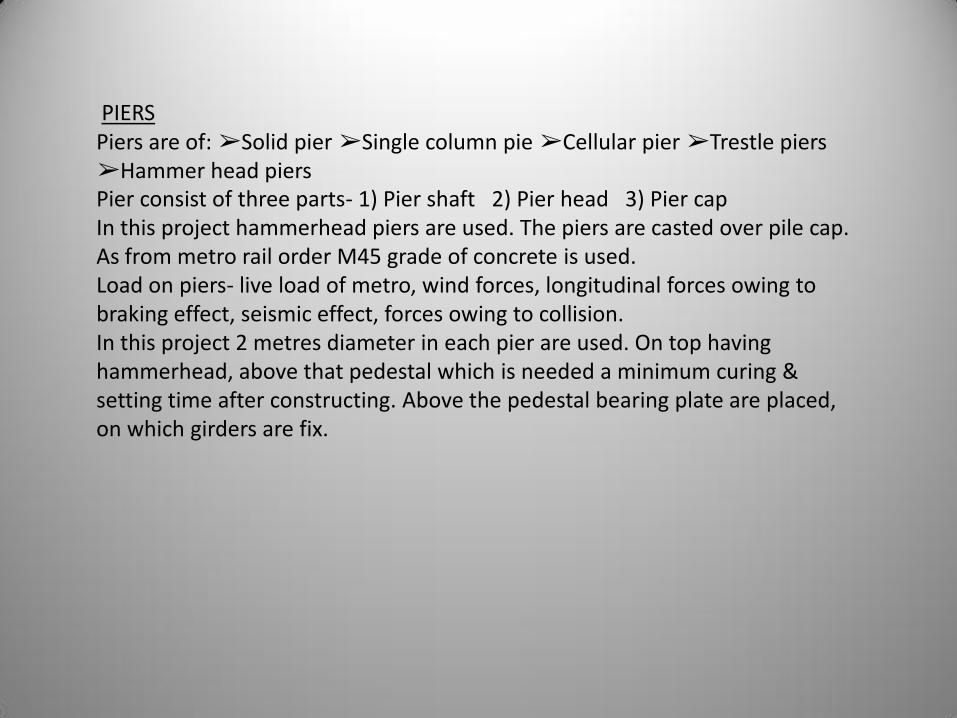
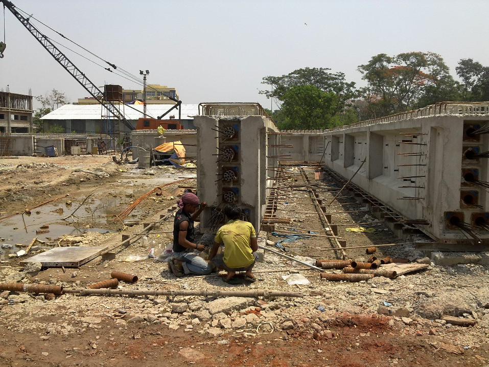
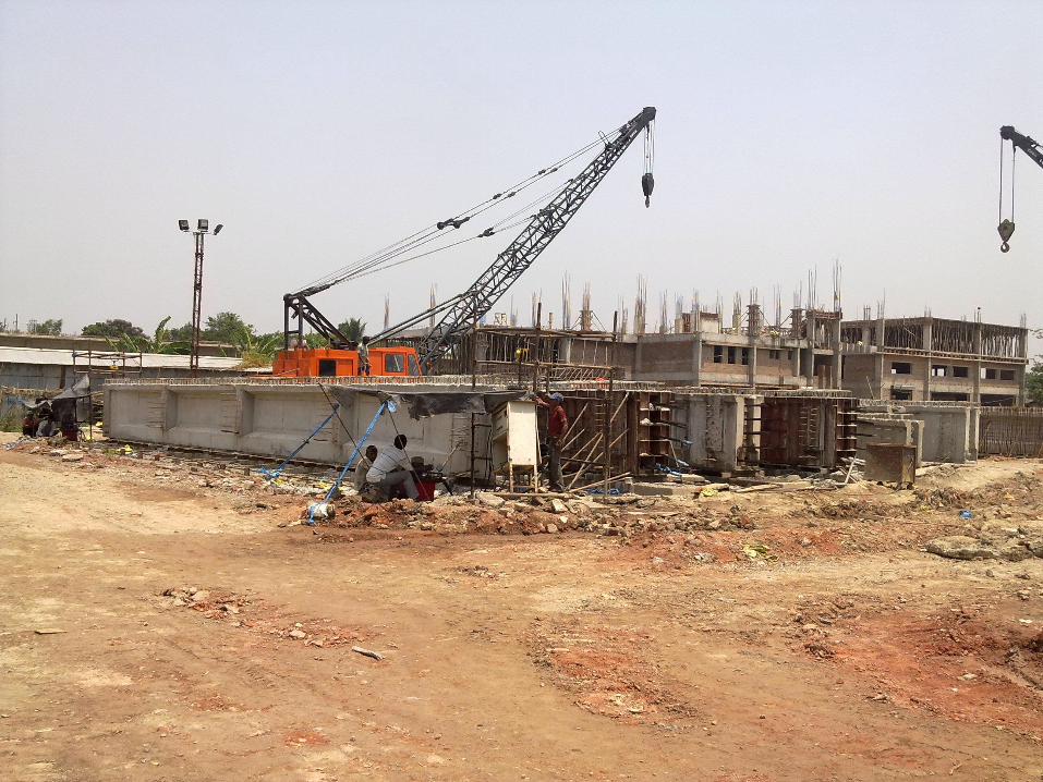
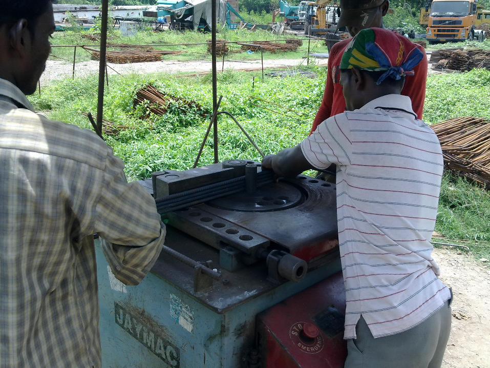
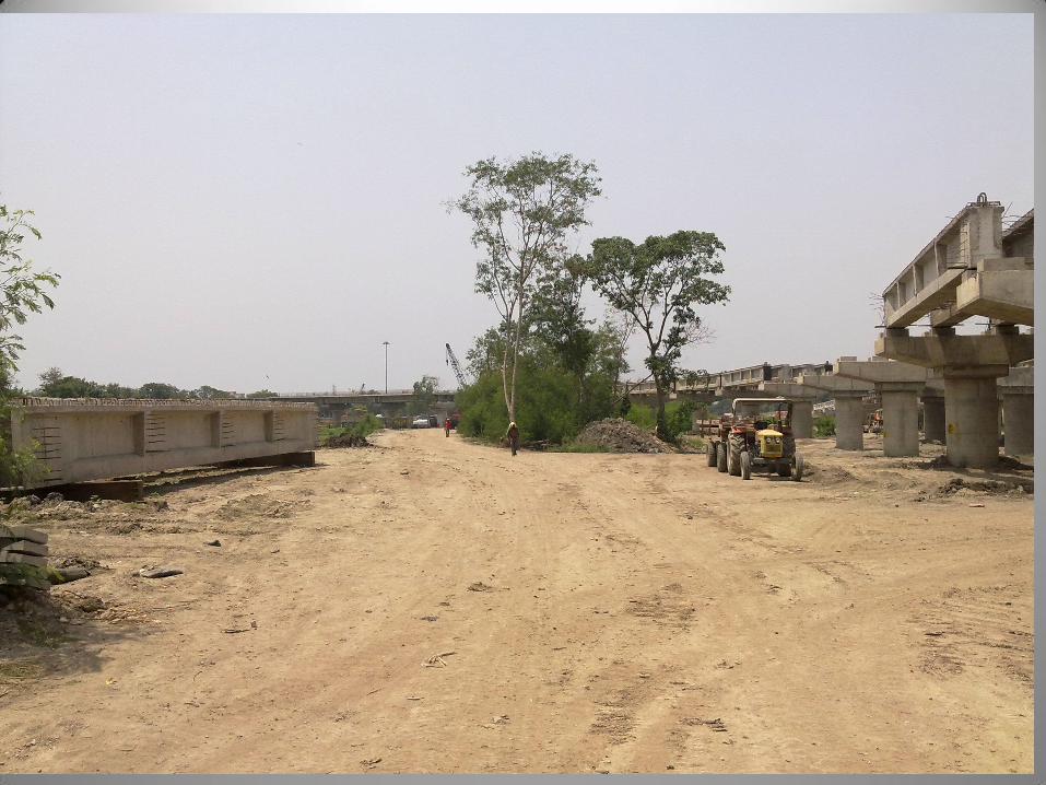
PIERS Piers are of: ➢Solid pier ➢Single column pie ➢Cellular pier ➢Trestle piers ➢Hammer head piers Pier consist of three parts- 1) Pier shaft 2) Pier head 3) Pier cap In this project hammerhead piers are used. The piers are casted over pile cap. As from metro rail order M45 grade of concrete is used. Load on piers- live load of metro, wind forces, longitudinal forces owing to braking effect, seismic effect, forces owing to collision. In this project 2 metres diameter in each pier are used. On top having hammerhead, above that pedestal which is needed a minimum curing & setting time after constructing. Above the pedestal bearing plate are placed, on which girders are fix.
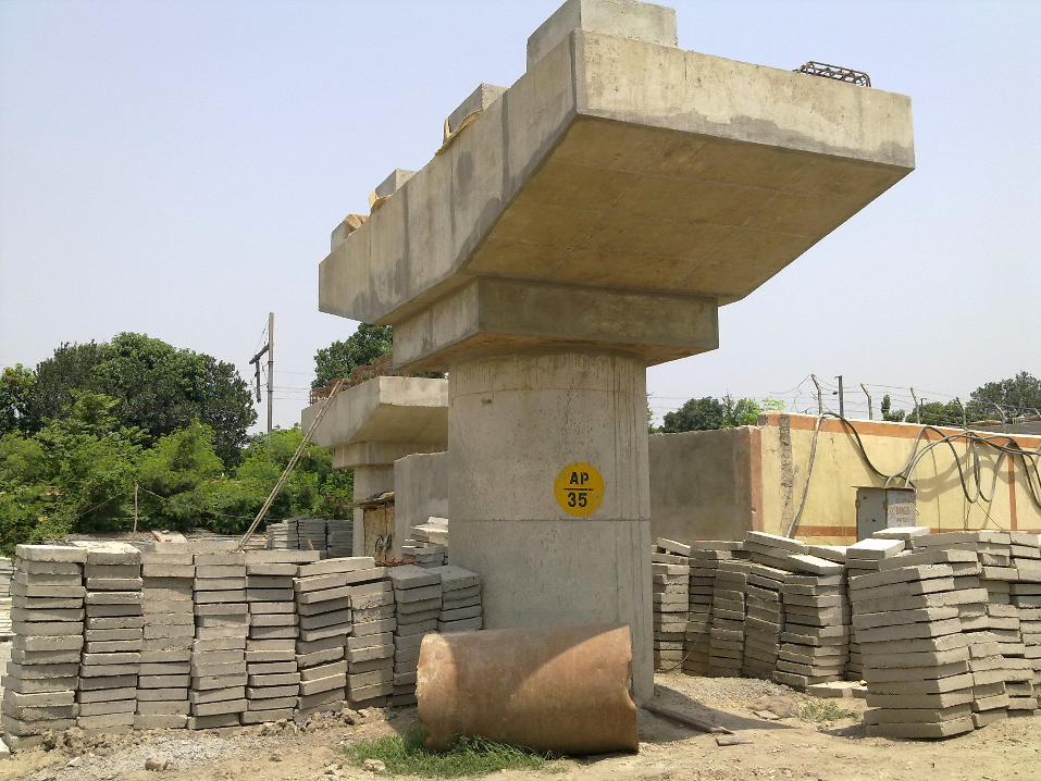
GIRDER The determination of the forces becomes simple since each track is carried by a pair of girders, spanned by the deck slab as they are assumed to act only as stiffeners to the girders. End diaphragms are designed to take up secondary forces that will be induced due to differential prestressing in girders. The shorter due concrete spans are provided with one pair of girders per track or a number of T beam and slabs placed side by side. In the matter case, the distribution of load between the girders is decided by using one of the standard methods evolved and mentioned subsection