![Trabajo de Investigacion Opu[1]](https://static.fdocument.pub/doc/165x107/55cf9acc550346d033a370d4/trabajo-de-investigacion-opu1.jpg)
Licensed Copy: opu-jwb94 opu-jwb94, Open University The ... EN 14324-2004 铜焊... · This British...
53
Licensed Copy: opu-jwb94 opu-jwb94, Open University The JISC, 01 November 2004, Uncontrolled Copy, (c) BSI
Transcript of Licensed Copy: opu-jwb94 opu-jwb94, Open University The ... EN 14324-2004 铜焊... · This British...
Lice
nsed
Cop
y: o
pu-jw
b94
opu-
jwb9
4, O
pen
Uni
vers
ity T
he J
ISC
, 01
Nov
embe
r 20
04, U
ncon
trol
led
Cop
y, (
c) B
SI
BRITISH STANDARD BS EN 14324:2004
Brazing — Guidance on the application of brazed joints
The European Standard EN 14324:2004 has the status of a British Standard
ICS 25.160.50
���������������� ������������������������������� �������������
Lice
nsed
Cop
y: o
pu-jw
b94
opu-
jwb9
4, O
pen
Uni
vers
ity T
he J
ISC
, 01
Nov
embe
r 20
04, U
ncon
trol
led
Cop
y, (
c) B
SI
标准分享网 www.bzfxw.com 免费下载

BS EN 14324:2004
This British Standard was published under the authority of the Standards Policy and Strategy Committee on 27 September 2004
© BSI 27 September 2004
ISBN 0 580 44516 X
National forewordThis British Standard is the official English language version of EN 14324:2004. It supersedes BS 1723-1:1986 and BS 1723-2:1986 which are withdrawn.
The UK participation in its preparation was entrusted to Technical Committee WEE/19, Brazing and bronze welding, which has the responsibility to:
A list of organizations represented on this committee can be obtained on request to its secretary.
Cross-references
The British Standards which implement international or European publications referred to in this document may be found in the BSI Catalogue under the section entitled “International Standards Correspondence Index”, or by using the “Search” facility of the BSI Electronic Catalogue or of British Standards Online.
This publication does not purport to include all the necessary provisions of a contract. Users are responsible for its correct application.
Compliance with a British Standard does not of itself confer immunity from legal obligations.
— aid enquirers to understand the text;
— present to the responsible international/European committee any enquiries on the interpretation, or proposals for change, and keep the UK interests informed;
— monitor related international and European developments and promulgate them in the UK.
Summary of pages
This document comprises a front cover, an inside front cover, the EN title page, pages 2 to 48, an inside back cover and a back cover.
The BSI copyright notice displayed in this document indicates when the document was last issued.
Amendments issued since publication
Amd. No. Date Comments
Lice
nsed
Cop
y: o
pu-jw
b94
opu-
jwb9
4, O
pen
Uni
vers
ity T
he J
ISC
, 01
Nov
embe
r 20
04, U
ncon
trol
led
Cop
y, (
c) B
SI

EUROPEAN STANDARD
NORME EUROPÉENNE
EUROPÄISCHE NORM
EN 14324
September 2004
ICS 25.160.50
English version
Brazing - Guidance on the application of brazed joints
Brasage fort - Guide d'application pour les assemblagesréalisés par brasage fort
Hartlöten - Anleitung zur Anwendung hartgelöteterVerbindungen
This European Standard was approved by CEN on 9 July 2004.
CEN members are bound to comply with the CEN/CENELEC Internal Regulations which stipulate the conditions for giving this EuropeanStandard the status of a national standard without any alteration. Up-to-date lists and bibliographical references concerning such nationalstandards may be obtained on application to the Central Secretariat or to any CEN member.
This European Standard exists in three official versions (English, French, German). A version in any other language made by translationunder the responsibility of a CEN member into its own language and notified to the Central Secretariat has the same status as the officialversions.
CEN members are the national standards bodies of Austria, Belgium, Cyprus, Czech Republic, Denmark, Estonia, Finland, France,Germany, Greece, Hungary, Iceland, Ireland, Italy, Latvia, Lithuania, Luxembourg, Malta, Netherlands, Norway, Poland, Portugal, Slovakia,Slovenia, Spain, Sweden, Switzerland and United Kingdom.
EUROPEAN COMMITTEE FOR STANDARDIZATIONC OM ITÉ EUR OP ÉEN DE NOR M ALIS AT IONEUROPÄISCHES KOMITEE FÜR NORMUNG
Management Centre: rue de Stassart, 36 B-1050 Brussels
© 2004 CEN All rights of exploitation in any form and by any means reservedworldwide for CEN national Members.
Ref. No. EN 14324:2004: E
Lice
nsed
Cop
y: o
pu-jw
b94
opu-
jwb9
4, O
pen
Uni
vers
ity T
he J
ISC
, 01
Nov
embe
r 20
04, U
ncon
trol
led
Cop
y, (
c) B
SI
标准分享网 www.bzfxw.com 免费下载
EN 14324:2004 (E)
2
Contents
page
Foreword..............................................................................................................................................................4 Introduction .........................................................................................................................................................5 1 Scope ......................................................................................................................................................6 2 Normative references ............................................................................................................................6 3 Terms and definitions ...........................................................................................................................6 4 Joint design............................................................................................................................................8 4.1 Principle..................................................................................................................................................8 4.2 Types of joint..........................................................................................................................................8 4.3 Assembly gap and brazing gap............................................................................................................9 4.3.1 General....................................................................................................................................................9 4.3.2 Influence of brazing filler materials ...................................................................................................11 4.3.3 Influence of parent material................................................................................................................11 4.3.4 Influence of dissimilar parent materials............................................................................................11 4.3.5 Influence of surface finish ..................................................................................................................12 4.3.6 Influence of atmospheres or fluxes ...................................................................................................13 4.4 Surface preparation.............................................................................................................................13 4.5 Stress distribution in service .............................................................................................................13 4.6 Application of filler material ...............................................................................................................13 4.7 Assembly ..............................................................................................................................................13 4.8 Good brazing design ...........................................................................................................................13 5 Materials ...............................................................................................................................................14 5.1 Parent materials ...................................................................................................................................14 5.1.1 Basic considerations...........................................................................................................................14 5.1.2 Special considerations........................................................................................................................14 5.2 Filler materials......................................................................................................................................17 5.2.1 General..................................................................................................................................................17 5.2.2 Forms available....................................................................................................................................18 5.2.3 Applications .........................................................................................................................................18 5.3 Fluxes....................................................................................................................................................19 5.3.1 General..................................................................................................................................................19 5.3.2 Flux removal.........................................................................................................................................19 5.4 Atmospheres ........................................................................................................................................20 5.4.1 Protective..............................................................................................................................................20 5.4.2 Vacuum atmospheres for brazing......................................................................................................20 5.5 Safety ....................................................................................................................................................20 6 Methods of brazing..............................................................................................................................22 7 Heat treatment......................................................................................................................................22 8 Inspection .............................................................................................................................................22 Annex A (informative) Examples of brazed assemblies .............................................................................23 Annex B (informative) Typical examples of joint design............................................................................26 Annex C (informative) Filler materials most commonly used for combinations of parent
materials ...............................................................................................................................................32
Lice
nsed
Cop
y: o
pu-jw
b94
opu-
jwb9
4, O
pen
Uni
vers
ity T
he J
ISC
, 01
Nov
embe
r 20
04, U
ncon
trol
led
Cop
y, (
c) B
SI
EN 14324:2004 (E)
3
Annex D (informative) Suitability of brazing filler material classes for the commoner brazing methods................................................................................................................................................33
Annex E (informative) Methods of brazing ..................................................................................................34 E.1 Flame brazing ......................................................................................................................................34 E.1.1 General .................................................................................................................................................34 E.1.2 Hand torch brazing..............................................................................................................................34 E.1.3 Mechanized flame brazing..................................................................................................................36 E.2 Induction brazing.................................................................................................................................37 E.2.1 Process.................................................................................................................................................37 E.2.2 Application ...........................................................................................................................................38 E.2.3 Advantages/limitations .......................................................................................................................38 E.2.4 Size limitations ....................................................................................................................................38 E.2.5 Safety....................................................................................................................................................38 E.3 Resistance brazing..............................................................................................................................39 E.3.1 Process.................................................................................................................................................39 E.3.2 Application ...........................................................................................................................................39 E.3.3 Advantages/limitations .......................................................................................................................39 E.3.4 Size limitations ....................................................................................................................................39 E.3.5 Safety....................................................................................................................................................40 E.4 Furnace brazing...................................................................................................................................40 E.4.1 Process variants..................................................................................................................................40 E.4.2 Protective atmosphere brazing..........................................................................................................40 E.4.3 Vacuum brazing...................................................................................................................................42 E.5 Immersion brazing...............................................................................................................................43 E.5.1 General .................................................................................................................................................43 E.5.2 Flux bath brazing.................................................................................................................................43 E.5.3 Dip bath brazing ..................................................................................................................................44 E.5.4 Salt bath brazing..................................................................................................................................45 E.6 Special methods ..................................................................................................................................46 E.6.1 Laser beam brazing.............................................................................................................................46 E.6.2 Brazing/braze welding with an arc.....................................................................................................47 E.6.3 Other methods .....................................................................................................................................47 Bibliography......................................................................................................................................................48
Lice
nsed
Cop
y: o
pu-jw
b94
opu-
jwb9
4, O
pen
Uni
vers
ity T
he J
ISC
, 01
Nov
embe
r 20
04, U
ncon
trol
led
Cop
y, (
c) B
SI
标准分享网 www.bzfxw.com 免费下载
EN 14324:2004 (E)
4
Foreword
This document (EN 14324:2004) has been prepared by Technical Committee CEN/TC 121 “Welding”, the secretariat of which is held by DIN.
This European Standard shall be given the status of a national standard, either by publication of an identical text or by endorsement, at the latest by March 2005, and conflicting national standards shall be withdrawn at the latest by March 2005.
According to the CEN/CENELEC Internal Regulations, the national standards organizations of the following countries are bound to implement this European Standard: Austria, Belgium, Cyprus, Czech Republic, Denmark, Estonia, Finland, France, Germany, Greece, Hungary, Iceland, Ireland, Italy, Latvia, Lithuania, Luxembourg, Malta, Netherlands, Norway, Poland, Portugal, Slovakia, Slovenia, Spain, Sweden, Switzerland and United Kingdom.
Lice
nsed
Cop
y: o
pu-jw
b94
opu-
jwb9
4, O
pen
Uni
vers
ity T
he J
ISC
, 01
Nov
embe
r 20
04, U
ncon
trol
led
Cop
y, (
c) B
SI

EN 14324:2004 (E)
5
Introduction
The purpose of this document is to provide information and guidance to users whose knowledge of brazing is limited, either as regards the whole process or in some specific areas. It is not intended to replace textbooks but to make readily available certain important information and hopefully prevent some common errors.
Brazing techniques offer a wide field for joining, cladding, building up and comparable applications where brazing filler materials can be used. Structures similar to brazed joints can be achieved by arc brazing processes (MIG, TIG, plasma), infra-red brazing and electron beam brazing, which are better described as braze welding.
Where the word 'material' is used for components, they can be metallic or non-metallic, except when the component can only be metallic, when it is so described. The same usage applies to filler materials, although the use of non-metallic filler materials is very limited.
Lice
nsed
Cop
y: o
pu-jw
b94
opu-
jwb9
4, O
pen
Uni
vers
ity T
he J
ISC
, 01
Nov
embe
r 20
04, U
ncon
trol
led
Cop
y, (
c) B
SI
标准分享网 www.bzfxw.com 免费下载

EN 14324:2004 (E)
6
1 Scope
This document gives guidance on the application of brazing and the manufacture of brazed joints. This standard gives an introduction to brazing and a basis for the understanding and use of brazing in different applications. Because of the wide range of applications of brazing this standard does not give detailed guidance that might be product specific. For such information reference should be made to the appropriate product standard or, for applications where this does not exist, the relevant criteria should be clearly established before any brazing is undertaken.
This standard covers joint design and assembly, material aspects for both parent material and filler materials, brazing process and process variables, pre- and post-braze treatment and inspection.
2 Normative references
The following referenced documents are indispensable for the application of this document. For dated references, only the edition cited applies. For undated references, the latest edition of the referenced document (including any amendments) applies. EN 1044:1999, Brazing — Filler metals.
EN 1045, Brazing — Fluxes for brazing — Classification and technical delivery conditions.
EN 12797, Brazing — Destructive tests of brazed joints.
EN 12799, Brazing — Non-destructive examination of brazed joints.
EN 13133, Brazing — Brazer approval.
EN 13134, Brazing — Procedure approval.
EN ISO 18279, Brazing — Imperfections in brazed joints (ISO 18279:2003).
3 Terms and definitions
For the purposes of this document, the following terms and definitions apply.
3.1 brazing joining process in which a filler material is used which has a liquidus temperatur above 450 °C, but below the solidus of the parent material, and which is mainly distributed in the brazing gap by capillary attraction
NOTE Other joining methods exist (see E.6.3).
3.2 brazed joint result of a joining process where the parent materials are not melted and the filling material and braze material have different chemical compositions compared to the parent materials
3.3 brazing gap narrow, mainly parallel gap at the brazing temperature between the components to be brazed (see Figure 1 and 4.3.4)
Lice
nsed
Cop
y: o
pu-jw
b94
opu-
jwb9
4, O
pen
Uni
vers
ity T
he J
ISC
, 01
Nov
embe
r 20
04, U
ncon
trol
led
Cop
y, (
c) B
SI
EN 14324:2004 (E)
7
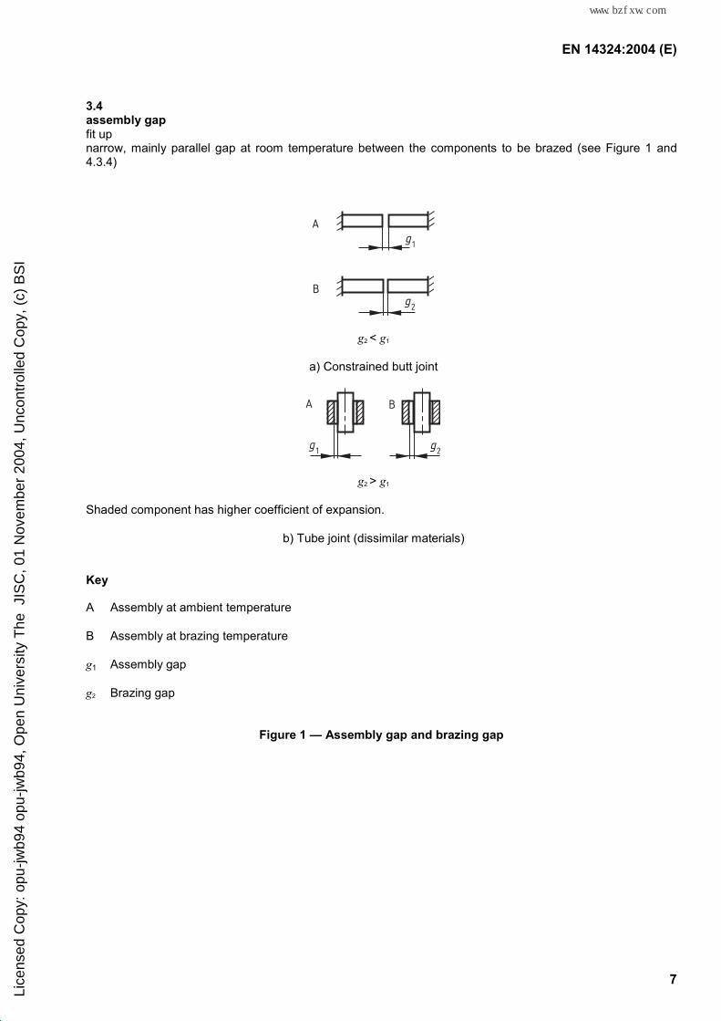
3.4 assembly gap fit up narrow, mainly parallel gap at room temperature between the components to be brazed (see Figure 1 and 4.3.4)
A
B
g1
g2
g2 < g1
a) Constrained butt joint
A B
g1 g2
g2 > g1
Shaded component has higher coefficient of expansion.
b) Tube joint (dissimilar materials)
Key
A Assembly at ambient temperature
B Assembly at brazing temperature
g1 Assembly gap
g2 Brazing gap
Figure 1 — Assembly gap and brazing gap
Lice
nsed
Cop
y: o
pu-jw
b94
opu-
jwb9
4, O
pen
Uni
vers
ity T
he J
ISC
, 01
Nov
embe
r 20
04, U
ncon
trol
led
Cop
y, (
c) B
SI
标准分享网 www.bzfxw.com 免费下载
EN 14324:2004 (E)
8
4 Joint design
4.1 Principle
The brazing process depends upon capillary flow of a molten brazing filler material between parts separated by a narrow gap. The filler material has a different composition from the components to be brazed. This compositional difference may affect the properties of the assembly in service, e.g. at elevated temperature, in corrosive media or under fatigue loading. In addition the properties of the parent material of the components to be brazed can be affected by the brazing cycle.
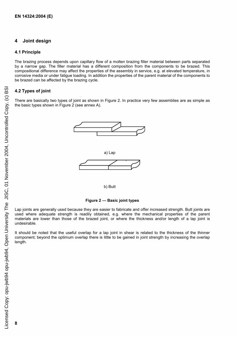
4.2 Types of joint
There are basically two types of joint as shown in Figure 2. In practice very few assemblies are as simple as the basic types shown in Figure 2 (see annex A).
a) Lap
b) Butt
Figure 2 — Basic joint types
Lap joints are generally used because they are easier to fabricate and offer increased strength. Butt joints are used where adequate strength is readily obtained, e.g. where the mechanical properties of the parent materials are lower than those of the brazed joint, or where the thickness and/or length of a lap joint is undesirable.
It should be noted that the useful overlap for a lap joint in shear is related to the thickness of the thinner component; beyond the optimum overlap there is little to be gained in joint strength by increasing the overlap length.
Lice
nsed
Cop
y: o
pu-jw
b94
opu-
jwb9
4, O
pen
Uni
vers
ity T
he J
ISC
, 01
Nov
embe
r 20
04, U
ncon
trol
led
Cop
y, (
c) B
SI

EN 14324:2004 (E)
9
4.3 Assembly gap and brazing gap
4.3.1 General
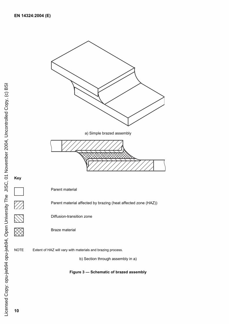
The areas of a brazed assembly are defined as shown schematically in Figure 3.
Perhaps the most critical feature in brazing is the control of the brazing gap, i.e. the gap at the brazing temperature, between the components to be brazed and through which the filler material has to flow by capillary action. There are several factors that influence the choice of the brazing gap and which have to be taken into consideration. It is essential to recognise that where joints are to be made between different parent materials, the assembly gap (fit up) will usually have to be different from the brazing gap (see 4.3.4).
NOTE The assembly gap may need to be larger or smaller than the brazing gap, depending on the thermal expansion coefficients of the materials, the configuration and the brazing process.
Different filler materials require different gaps even within the same group, as can be seen from the typical ranges given in Table 1, but the optimum gap may also be affected by a number of other joint parameters (see example in Figure 4), e.g.:
parent material(s);
geometry of the joint;
surface finish of the faying surfaces;
use of a flux or protective atmosphere;
careful control of brazing temperature and heating rate;
brazing process.
Table 1 — Typical brazing gaps
Filler material class according to EN 1044
Brazing gapa
mm
AL 0,05 to 0,25
AG 0,05 to 0,30
CP 0,05 to 0,30
CU1XX
CU2XX & CU3XX
Up to 0,15
0,05 to 0,20
NI Up to 0,15
AU Up to 0,10
a Brazing gap will depend on the selected filler materials, the
brazing process and the brazing conditions.
Lice
nsed
Cop
y: o
pu-jw
b94
opu-
jwb9
4, O
pen
Uni
vers
ity T
he J
ISC
, 01
Nov
embe
r 20
04, U
ncon
trol
led
Cop
y, (
c) B
SI
标准分享网 www.bzfxw.com 免费下载
EN 14324:2004 (E)
10
a) Simple brazed assembly
Key
Parent material
Parent material affected by brazing (heat affected zone (HAZ))
Diffusion-transition zone
Braze material
NOTE Extent of HAZ will vary with materials and brazing process.
b) Section through assembly in a)
Figure 3 — Schematic of brazed assembly
Lice
nsed
Cop
y: o
pu-jw
b94
opu-
jwb9
4, O
pen
Uni
vers
ity T
he J
ISC
, 01
Nov
embe
r 20
04, U
ncon
trol
led
Cop
y, (
c) B
SI
EN 14324:2004 (E)
11
0
1
2
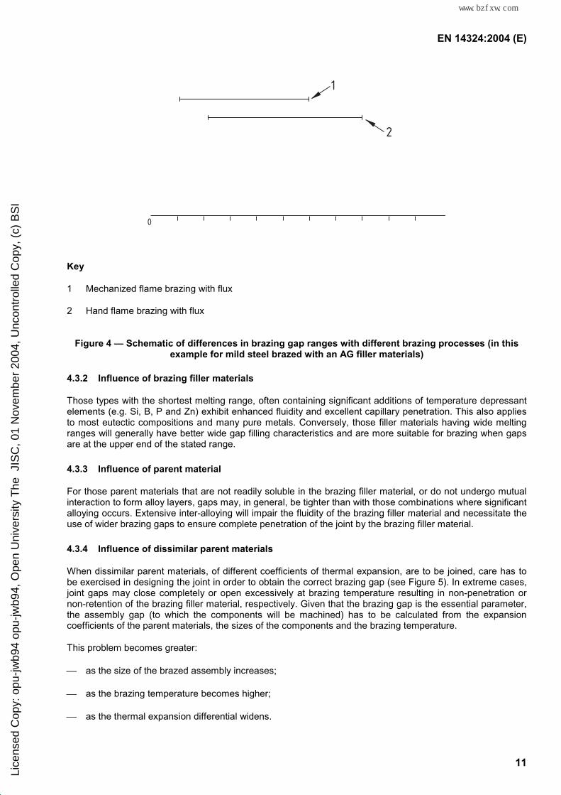
Key
1 Mechanized flame brazing with flux
2 Hand flame brazing with flux
Figure 4 — Schematic of differences in brazing gap ranges with different brazing processes (in this example for mild steel brazed with an AG filler materials)
4.3.2 Influence of brazing filler materials
Those types with the shortest melting range, often containing significant additions of temperature depressant elements (e.g. Si, B, P and Zn) exhibit enhanced fluidity and excellent capillary penetration. This also applies to most eutectic compositions and many pure metals. Conversely, those filler materials having wide melting ranges will generally have better wide gap filling characteristics and are more suitable for brazing when gaps are at the upper end of the stated range.
4.3.3 Influence of parent material
For those parent materials that are not readily soluble in the brazing filler material, or do not undergo mutual interaction to form alloy layers, gaps may, in general, be tighter than with those combinations where significant alloying occurs. Extensive inter-alloying will impair the fluidity of the brazing filler material and necessitate the use of wider brazing gaps to ensure complete penetration of the joint by the brazing filler material.
4.3.4 Influence of dissimilar parent materials
When dissimilar parent materials, of different coefficients of thermal expansion, are to be joined, care has to be exercised in designing the joint in order to obtain the correct brazing gap (see Figure 5). In extreme cases, joint gaps may close completely or open excessively at brazing temperature resulting in non-penetration or non-retention of the brazing filler material, respectively. Given that the brazing gap is the essential parameter, the assembly gap (to which the components will be machined) has to be calculated from the expansion coefficients of the parent materials, the sizes of the components and the brazing temperature.
This problem becomes greater:
as the size of the brazed assembly increases;
as the brazing temperature becomes higher;
as the thermal expansion differential widens.
Lice
nsed
Cop
y: o
pu-jw
b94
opu-
jwb9
4, O
pen
Uni
vers
ity T
he J
ISC
, 01
Nov
embe
r 20
04, U
ncon
trol
led
Cop
y, (
c) B
SI
标准分享网 www.bzfxw.com 免费下载

EN 14324:2004 (E)
12
b
a
ds
dm
1
2B
A
Key
1 Molybdenum
2 Steel
A Assembly at ambient temperature
B Assembly at brazing temperature
ds Outer diameter of steel part (before brazing)
dm Inner diameter of molybdenum part (before brazing)
a Assembly gap
b Brazing gap
Thermal expansion coefficient α α steel > α molybdenum
Figure 5 — Influence on the brazing gap of dissimilar parent materials with different thermal expansion coefficients (schematic)
4.3.5 Influence of surface finish
Too coarse or too fine a surface finish will adversely affect the filling of the joint gap. The flow of the filler material may be influenced by the surface finishes of the joint materials.
Lice
nsed
Cop
y: o
pu-jw
b94
opu-
jwb9
4, O
pen
Uni
vers
ity T
he J
ISC
, 01
Nov
embe
r 20
04, U
ncon
trol
led
Cop
y, (
c) B
SI
EN 14324:2004 (E)
13
4.3.6 Influence of atmospheres or fluxes
Processes using a protective atmosphere or a vacuum will tolerate tighter joint gaps, with given brazing filler materials, than an equivalent process where a flux is used. Unless joint gaps are adequate, flux and gas pockets will be by-passed and become entrapped in the finished joint.
4.4 Surface preparation
The component parts of a joint should be clean and properly fitting. When required by the brazing method, oxide, grease and oil should be removed by chemical, thermal and/or mechanical methods. This may involve degreasing, pickling, scratch brushing and other similar processes. The surface of the component within the brazed joint should not be polished. A roughened surface will assist filler materials flow particularly in the direction of machining. To improve the fit-up it may be necessary to modify the surface by methods such as knurling. To improve wettablilty of materials such as nickel alloys containing titanium and aluminium, and ceramics, it may be necessary to cover the surfaces with a suitable material, e.g. by plating or metallizing.
To prevent the flow of filler materials outside the joint area, it may be necessary to apply a 'stopping-off' agent. Care should be taken that this does not penetrate into the capillary joint gap and inhibit flow.
The degree of cleanliness required depends upon the ultimate quality required of the component and also the brazing process to be used. The degree of preparation is most severe for flux-free controlled atmosphere brazing at higher temperatures.
4.5 Stress distribution in service
Figure B.1 illustrates design modifications which endeavour to remove high stress concentrations from joint edges and distribute the stress more evenly in the parent materials.
4.6 Application of filler material
The brazing filler material is available in various forms (see 5.2.2).
For hand torch brazing applications, the brazing filler material is generally hand fed as rod or wire but may be pre-placed. In mechanized brazing applications, the brazing filler material is either pre-placed or automatically fed. In furnace brazing it has to be pre-placed. Examples of filler material placement are shown in Figure B.2.
The point at which the filler material is applied can greatly affect the quality of the joint. Internal pre-placement can also serve to demonstrate that capillary flow through the joint has occurred.
4.7 Assembly
It is essential, when designing joints, to ensure that the component parts will retain the required relationship during the brazing process. There are several effective methods of achieving this (see Figure B.3).
4.8 Good brazing design
Examples of good brazing design are given in Tables B.1 and B.2.
Lice
nsed
Cop
y: o
pu-jw
b94
opu-
jwb9
4, O
pen
Uni
vers
ity T
he J
ISC
, 01
Nov
embe
r 20
04, U
ncon
trol
led
Cop
y, (
c) B
SI
标准分享网 www.bzfxw.com 免费下载
EN 14324:2004 (E)
14
5 Materials
5.1 Parent materials
5.1.1 Basic considerations
The wide range of materials in current use precludes the listing of every grade which is amenable to joining by the brazing process. General categories are listed here for guidance purposes but other less common materials may well be applicable. If an unlisted material is specified, advice should be sought from the brazing filler manufacturer.
a) Aluminium and its alloys. Pure aluminium, aluminium-zinc (< 6 %), aluminium-manganese (< 2 %), aluminium-silicon (< 2 %), aluminium-magnesium (< 2 %).
b) Coated materials. Materials with electrodeposited or other coatings.
c) Cobalt and its alloys. Pure cobalt, hard facing alloys, corrosion-resistant alloys.
d) Copper and its alloys. Copper (unalloyed, phosphorus-bearing, silver-bearing), low alloyed copper alloys (formerly designated as e.g. beryllium-copper, chromium-copper and others), copper-zinc alloys (brasses), copper-tin alloys (tin-bronzes/ phosphor-bronzes, including some gunmetals), copper-tin-lead alloys (including some gunmetals), copper-nickel-zinc alloys (nickel-silvers), copper-nickel-alloys (cupro-nickel), copper-aluminium alloys (aluminium bronzes), copper-manganese-aluminium alloys.
e) Ferrous metals. Cast iron, malleable iron, mild steel, carbon and low alloy steels, alloy steels, high speed and tool steels, stainless, heat and corrosion-resistant steels.
f) Nickel and its alloys. Pure nickel, nickel-copper, nickel-iron, nickel-chromium-iron, nickel-chromium.
g) Precious metals. Gold, platinum, palladium, silver and their alloys.
h) Refractory metals and alloys. Titanium, zirconium, tantalum, niobium and their alloys.
i) Tungsten and molybdenum. Tungsten, molybdenum, cemented carbides, silver–tungsten, copper-tungsten.
j) Non-metallic materials. For example, ceramics, graphite, tungsten carbide, diamonds, cermets, glass, sapphire.
5.1.2 Special considerations
5.1.2.1 General
Some of the parent materials listed in 5.1.1 may have their properties adversely affected by the brazing process, either because of the effects of temperature or because of metallurgical interactions. In addition, consideration needs to be given to the effects that may arise in the brazing of dissimilar materials. Therefore, the points in 5.1.2.2 to 5.1.2.13 need to be considered when the brazing of such materials is proposed.
Lice
nsed
Cop
y: o
pu-jw
b94
opu-
jwb9
4, O
pen
Uni
vers
ity T
he J
ISC
, 01
Nov
embe
r 20
04, U
ncon
trol
led
Cop
y, (
c) B
SI
EN 14324:2004 (E)
15
5.1.2.2 Dissimilar parent materials
One advantage of brazing is that many combinations of parent materials can be joined, but the effects of the brazing cycle on their physical and metallurgical characteristics always need to be considered.
The primary physical property to be considered is the coefficient of thermal expansion. This has two main effects. The gap between the components at brazing temperature will not be the same as the assembly gap (for which allowance has to be made in designing the joint). There may also be sufficient residual stress after brazing to cause mechanical failure. Depending on the form of the joint, this can cause severe distortion or even cracking, e.g. as sometimes occurs in the brazing of carbide tool tips to shanks, and allowance can be made for this by using the appropriate filler form or joint design to produce a thick compliant joint.
Metallurgical effects can influence the mechanical properties of the joint. In some cases brittle compounds may be formed but in other cases the joint may be strengthened.
5.1.2.3 Effects of brazing process on parent material properties
Where an alloy to be brazed depends for its strength on work hardening, hardening will be minimized by the brazing operation and this cannot be recovered. Precipitation hardenable alloys may be affected by the brazing operation: it may be possible to recover any loss in strength by suitable heat treatment. In some cases consideration needs to be given to changes in the corrosion properties caused by the brazing process. Information should be sought from the parent material supplier about these effects.
5.1.2.4 Alloys with tenacious surface oxides
Parent alloys containing additions forming tenacious oxide films are more difficult to braze than parent materials of the same system that do not. The most common additions are aluminium and titanium in stainless steels and nickel alloys. Such parent material will require special attention both in respect of surface preparation prior to brazing and the degree of protection provided by the flux or atmosphere used during the process, e.g. special fluxes or atmospheres or plating before brazing.
5.1.2.5 Porous metals
Components produced by powder metallurgical processes which have connected porosity (less than about 90 % of theoretical density) may prove difficult to braze because of capillary absorption of the filler materials. Sealing of the surface prior to brazing will be necessary in such cases.
5.1.2.6 Metals and alloys containing reducible oxides
Metals or alloys containing oxide inclusions or dissolved oxygen, which are easily reduced at the brazing temperature, shall not be brazed in a reducing atmosphere; the oxide inclusion can form steam causing porosity and loss of ductility.
5.1.2.7 Aluminium alloys
The filler materials used for brazing aluminium and its alloys are normally based on the Al-Si system. If the parent material contains magnesium as an addition, this reacts with the silicon in the brazing alloy to form an intermetallic compound at the interface. If the level of magnesium is more than 2 %, the amount of intermetallic compound at the interface may embrittle the joint.
Lice
nsed
Cop
y: o
pu-jw
b94
opu-
jwb9
4, O
pen
Uni
vers
ity T
he J
ISC
, 01
Nov
embe
r 20
04, U
ncon
trol
led
Cop
y, (
c) B
SI
标准分享网 www.bzfxw.com 免费下载
EN 14324:2004 (E)
16
5.1.2.8 Lead-bearing copper alloys
Lead is added to various copper alloys, e.g. to improve machinability, it being insoluble in copper and its alloys. If above about 2 %, lead may interfere with brazing
a) by forming an unwettable dross at the interface; and
b) by causing cracking.
These effects can be reduced by adequate fluxing and uniform heating without imposed stress.
5.1.2.9 Free machining carbon steels
Lead and sulphur are added to carbon steels to improve machinability. Lead additions below 0,35 % are not considered to reduce brazeability or joint strength, but higher levels may result in low joint strengths because of interaction with the filler material. When vacuum furnace brazing, it should be noted that lead will volatize from the surface of the steel.
Sulphur-bearing free machining carbon steels, which typically contain up to 0,6 % sulphur, are readily brazed. Joint strengths are comparable with sulphur-free grades.
5.1.2.10 Cast iron
Spheroidal graphite (s.g.) cast irons are fairly readily brazed with silver filler materials but flake graphite irons are more troublesome because the flakes interfere with wetting. One remedy is special surface treatments to remove the flakes, or an alternative may be to use a silver brazing filler material containing nickel.
5.1.2.11 Reactive and refractory metals and their alloys
Titanium, zirconium, niobium and tantalum and their alloys are not normally brazed and specialist advice should be sought before it is attempted. It is essential that an inert atmosphere is always used (argon or vacuum) and that hydrogen-bearing atmospheres are never used.
Molybdenum and tungsten can be brazed in hydrogen as well as in inert atmospheres. However, it is preferable that the brazing temperatures are below the recrystallization temperature, otherwise the parent material can be severely embrittled.
5.1.2.12 Metals prone to cracking during brazing
The main cause of cracking is the stressing of components while in contact with molten filler material. This stress may originate from work hardening of the parent material, from restraint imposed by a jig or from uneven heating. The cracking occurs at grain boundaries which tend to fill with brazing filler material. The phenomenon is sometimes called stress cracking or liquid metal penetration. To prevent this, annealed material should be used where applicable, even heating should be ensured and jigs designed to avoid restraint.
5.1.2.13 Non-metallic materials
Ceramics may be brazed either by previously metallizing the ceramic surface or by using reactive metal filler materials.
For glass materials special glass filler materials are available.
Lice
nsed
Cop
y: o
pu-jw
b94
opu-
jwb9
4, O
pen
Uni
vers
ity T
he J
ISC
, 01
Nov
embe
r 20
04, U
ncon
trol
led
Cop
y, (
c) B
SI
EN 14324:2004 (E)
17
5.2 Filler materials
5.2.1 General
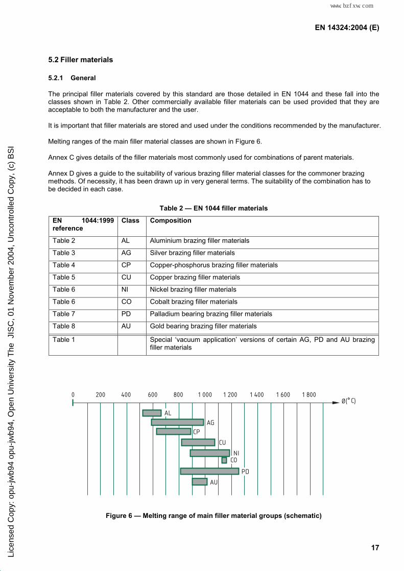
The principal filler materials covered by this standard are those detailed in EN 1044 and these fall into the classes shown in Table 2. Other commercially available filler materials can be used provided that they are acceptable to both the manufacturer and the user.
It is important that filler materials are stored and used under the conditions recommended by the manufacturer.
Melting ranges of the main filler material classes are shown in Figure 6.
Annex C gives details of the filler materials most commonly used for combinations of parent materials.
Annex D gives a guide to the suitability of various brazing filler material classes for the commoner brazing methods. Of necessity, it has been drawn up in very general terms. The suitability of the combination has to be decided in each case.
Table 2 — EN 1044 filler materials
EN 1044:1999 reference
Class Composition
Table 2 AL Aluminium brazing filler materials
Table 3 AG Silver brazing filler materials
Table 4 CP Copper-phosphorus brazing filler materials
Table 5 CU Copper brazing filler materials
Table 6 NI Nickel brazing filler materials
Table 6 CO Cobalt brazing filler materials
Table 7 PD Palladium bearing brazing filler materials
Table 8 AU Gold bearing brazing filler materials
Table 1 Special ‘vacuum application’ versions of certain AG, PD and AU brazing filler materials
200 400 600 800 1 000 1 200 1 400 1 600 1 8000
CP
CU
NI
AG
CO
AU
AL
PDPD
Ø( C)
Figure 6 — Melting range of main filler material groups (schematic)
Lice
nsed
Cop
y: o
pu-jw
b94
opu-
jwb9
4, O
pen
Uni
vers
ity T
he J
ISC
, 01
Nov
embe
r 20
04, U
ncon
trol
led
Cop
y, (
c) B
SI
标准分享网 www.bzfxw.com 免费下载
EN 14324:2004 (E)
18
5.2.2 Forms available
The normal forms available include rod, wire, foil, preforms, powder, paste and clad sheet. A few brazing filler materials may also be sprayed, coated or vacuum deposited or blended from powders. The forms in which the brazing filler material are available should be determined at the design stage.
5.2.3 Applications
5.2.3.1 General
The choice of filler material for brazing a given combination of parent materials depends upon many factors, in some cases there will only be one possibility, in others, several. Not every filler material in a class can be used in a specific case.
5.2.3.2 Class AL
The filler materials in this class are used almost exclusively for the joining of pure aluminium and a restricted range of aluminium alloys.
5.2.3.3 Class AG
Silver brazing filler materials find wide application in the brazing of materials given in 5.1 with the exception of aluminium, magnesium and refractory metals and their alloys. Special grades are available for vacuum applications.
5.2.3.4 Class CP
These filler materials are usually restricted to joining copper and its alloys. With the exception of CP302, they are self-fluxing on copper, but a flux or protective atmosphere is required on most copper alloys. These phosphorus-bearing filler materials are not normally used for joining steel or nickel alloys, as brittle phases may be formed.
5.2.3.5 Class CU
These filler materials are generally used for brazing copper, cemented carbide and ferrous components (CU3XX with a flux) and for brazing of ferrous and some other high melting parent materials in a protective atmosphere or vacuum (CU1XX and CU2XX).
5.2.3.6 Class NI and CO
These filler materials are used almost exclusively for joining stainless steel and other heat and corrosion-resistant alloys in either vacuum or protective atmospheres.
5.2.3.7 Class PD and AU
These filler materials are used in protective atmospheres or vacuum to join metallized ceramics, copper alloys, nickel alloys and steels.
Lice
nsed
Cop
y: o
pu-jw
b94
opu-
jwb9
4, O
pen
Uni
vers
ity T
he J
ISC
, 01
Nov
embe
r 20
04, U
ncon
trol
led
Cop
y, (
c) B
SI
EN 14324:2004 (E)
19
5.3 Fluxes
5.3.1 General
Fluxes are an essential requirement when brazing in air, with the general exception of the self-fluxing copper-phosphorus filler materials. Fluxes are also an integral part of all flux bath processes. In some circumstances they are used in protective atmosphere brazing operations.
The most commonly available forms are powder and paste. Alternatives include gases and liquids, flux-coated or cored filler materials and flux/filler material mixtures.
Fluxes are generally applied prior to heating.
Fluxes for brazing shall be as standardized in EN 1045.
5.3.2 Flux removal
5.3.2.1 General
Some flux residues are chemically active and their complete removal is essential if undesirable corrosion of the parent material is to be avoided.
The method of their removal will depend largely on the stage of exhaustion attained by the flux at the completion of the brazing cycle. This will depend upon the use of an adequate amount of the appropriate flux, avoidance of overheating and a heating time as short as possible. Provided that the assembly can sustain such treatment without damage, flux removal may be facilitated by quenching the assembly into water immediately after the brazing filler material has solidified.
Flux residues should be disposed of in accordance with the relevant regulations.
5.3.2.2 Fluxes for brazing ≥ 750 °C (e.g. FH21, FH30)
The fused residues from borax and similar high temperature fluxes are hard, glassy and relatively insoluble in water. Therefore they have to be removed mechanically, e.g. by grit or shot blasting or abrasive techniques.
5.3.2.3 Fluxes for brazing < 750 °C (e.g. FH10, FH11, FH12)
Residues from fluoroborate fluxes are relatively water soluble and may be removed in hot or boiling water. The efficiency of flux removal may be improved by agitation or ultrasonic vibration. Chemical or proprietary inhibited descaling solution may be used where complete removal of all residual discoloration is required. Non-immersion methods which are equally effective include steam lancing and wet or dry abrasive techniques.
5.3.2.4 Aluminium brazing fluxes
Type FL10 fluxes are highly corrosive and require very careful post-braze removal. The flux residues are water soluble and can be washed away. Type FL20 fluxes are generally non-corrosive and the residue can often be left in situ.
Lice
nsed
Cop
y: o
pu-jw
b94
opu-
jwb9
4, O
pen
Uni
vers
ity T
he J
ISC
, 01
Nov
embe
r 20
04, U
ncon
trol
led
Cop
y, (
c) B
SI
标准分享网 www.bzfxw.com 免费下载

EN 14324:2004 (E)
20
5.4 Atmospheres
5.4.1 Protective
Examples of types of protective atmosphere are listed in Table 3.
Users should understand that the effects of atmospheric purity, cycle time and temperature are interrelated and will affect the requirements for satisfactory brazing. The function of a protective atmosphere is to ensure the cleanliness of the parent and filler materials so that the latter can flow freely during brazing.
The choice of atmosphere will be influenced by the parent and filler materials and may be active or inert.
5.4.2 Vacuum atmospheres for brazing
A vacuum atmosphere is achieved in a vessel specifically designed for brazing or heat treatment by pumping out the furnace gases, usually air. The pumps are generally a carefully designed combination of mechanical and oil diffusion which are matched in pumping capacity, and of sufficient size to evacuate rapidly the furnace space. Outgassing of the charge of components and the interior of the furnace will occur during the heating cycle, and the pumps are frequently automatically interlocked with vacuum measuring instruments to accommodate this.
A vacuum of better than 10–3 mbar is easily achieved, but a low leak rate is equally important to control the residual atmosphere. 10–3 mbar is equivalent to a gas impurity content of approximately 1,1 × 10⁻⁶ (parts per million) by volume.
5.5 Safety
The manufacturer's advice should be sought to ensure that the flux, atmospheres, filler material and parent materials are compatible.
Lice
nsed
Cop
y: o
pu-jw
b94
opu-
jwb9
4, O
pen
Uni
vers
ity T
he J
ISC
, 01
Nov
embe
r 20
04, U
ncon
trol
led
Cop
y, (
c) B
SI

EN 14324:2004 (E)
21
Table 3 — Examples of protective atmospheres
Approximate composition Applications No. Source Typical dew point of incoming gas
°C
H2
%
N2
%
CO
%
CO2
%
Filler material class
Parent materials
1 Combusted fuel gasd (low hydrogen)
Up to + 30 1 to 5 87 1 to 5 11 to 12 AGa, CP, CU3XXa
Cu and some Cu alloys. Low and medium carbon steels
2 Combusted fuel gasd (decarburizing)
Up to + 30 14 to 15 70 to 71 9 to 10 5 to 6 AGa ,CP, CU1XX, CU2XX CU3XXa
Cu and some Cu alloys, low and medium C steel, Ni, Ni-Cu alloy
3 Combusted fuel gasf, dried
- 40 15 to 16 73 to 75 10 to 11 - AGa,CP, CU1XX, CU2XX, CU3XXa
Cu and some Cu alloys, carbon steels, Ni-Cu alloy, Ni, Ni-Fe alloys
4 Combusted fuel gase, dried (carburizing)
- 40 38 to 40 41 to 45 17 to 19 - AGa ,CP, CU1XX, CU3XXa
Cu and some Cu alloys, carbon steels, Ni-Cu alloy, Ni
5 Dissociated ammoniag (cracked ammonia)
- 54 75 25 - - AG, CP CU1XX, CU2XX, CU3XX, NI106, NI107
Cu and some Cu alloys, carbon steels, Ni-Cu alloy, Ni and Ni alloys, alloys containing Crb
6 Cylinder hydrogen
Down to
- 60
100 d - - AG, CP, CU1XX, CU2XX, CU3XX, NI107
Cu and some Cu alloys, low and medium carbon steels, Ni and Ni alloys and alloys of Co, Cr and cemented carbidesb
7 Inert gasg, e.g. argon, nitrogenc
Below – 60 - - - - CP,CU1XX, CU2XX, NI
Cu and some Cu alloys, carbon steels, Ni and Ni alloysb, alloys containing Cr
a Flux additionally required when filler materials containing volatile elements are used. b Flux required in addition to atmosphere when appreciable quantities of aluminium, titanium, silicon or beryllium are present. c It is essential that nitrogen is not used with refractory metals or aluminium or when the filler material contains boron or silicon. d The combusted fuel gas (low hydrogen or decarburizing) may be referred to as exothermic. It may also be available as synthetic gas. e The combustable fuel gas (carburizing) may be referred to as endothermic. It may also be available as synthetic gas. f It may also be available as synthetic gas. g Certain filler materials in EN 1044:1999 Tables 7 and 8, can be brazed in protective atmospheres 5 and 7
Lice
nsed
Cop
y: o
pu-jw
b94
opu-
jwb9
4, O
pen
Uni
vers
ity T
he J
ISC
, 01
Nov
embe
r 20
04, U
ncon
trol
led
Cop
y, (
c) B
SI
标准分享网 www.bzfxw.com 免费下载

EN 14324:2004 (E)
22
6 Methods of brazing
Annex E gives details of the different method of brazing, including the advantages and limitations of each method.
7 Heat treatment
Where the parent materials require heat treatment, it may be possible to carry this out as part of the brazing operation. In other cases it will be necessary to carry out heat treatment separately. If the subsequent heat treatment requires quenching, there is a risk of distortion and/or cracking.
8 Inspection
Where applicable, brazer qualification in accordance with EN 13133, brazing procedure qualification in accordance with EN 13134, non-destructive testing of brazed joints in accordance with EN 12797 and destructive testing of brazed joints in accordance with EN 12799 shall be used. Details of imperfections shall be as given in EN ISO 18279.
Specific requirements that are important to the purchaser and supplier should be established before any work is carried out, so that errors and misjudgements can be avoided. A list of relevant items is given below from which the purchaser/supplier can select those that are most applicable:
a) location where work is to be carried out (workshop or site);
b) design of assembly:
1) interacting effects if subsequent processing is required, e.g. hardening or plating;
2) jigs, fixtures, etc.;
3) surface stop-off and protection of surfaces where filler material is not to flow;
c) inspection procedures, including sampling;
d) materials to be used and method of identification;
e) process and controls (if any) to be identified;
f) method of cleaning and oxide removal where necessary;
g) surface finish of components to be brazed and tolerances on fit-up;
h) achievement of satisfactory brazing cycles and means of avoiding overheating/overcooling;
i) post-braze cleaning and treatment to remove flux and surface finish requirements;
j) removal of surplus filler material;
k) repair of defective joints;
l) equipment controls and maintenance requirements;
m) recording of test results.
Lice
nsed
Cop
y: o
pu-jw
b94
opu-
jwb9
4, O
pen
Uni
vers
ity T
he J
ISC
, 01
Nov
embe
r 20
04, U
ncon
trol
led
Cop
y, (
c) B
SI
EN 14324:2004 (E)
23
Annex A (informative)
Examples of brazed assemblies
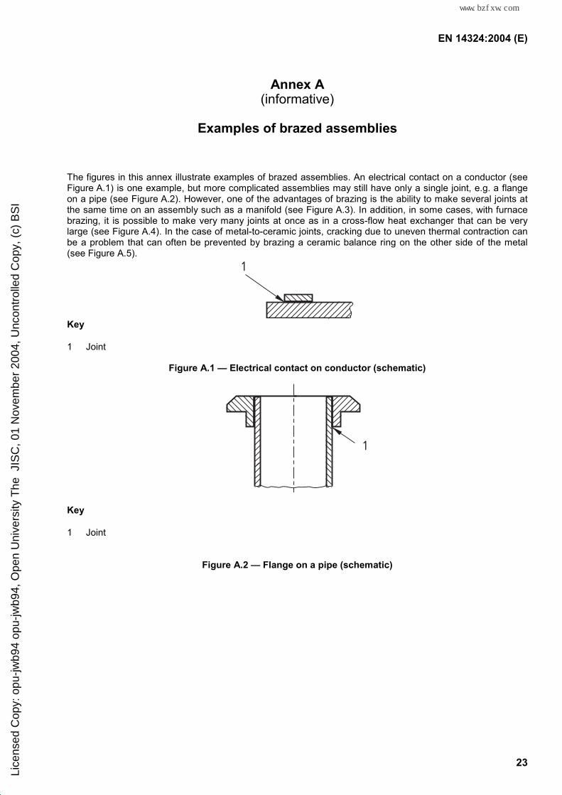
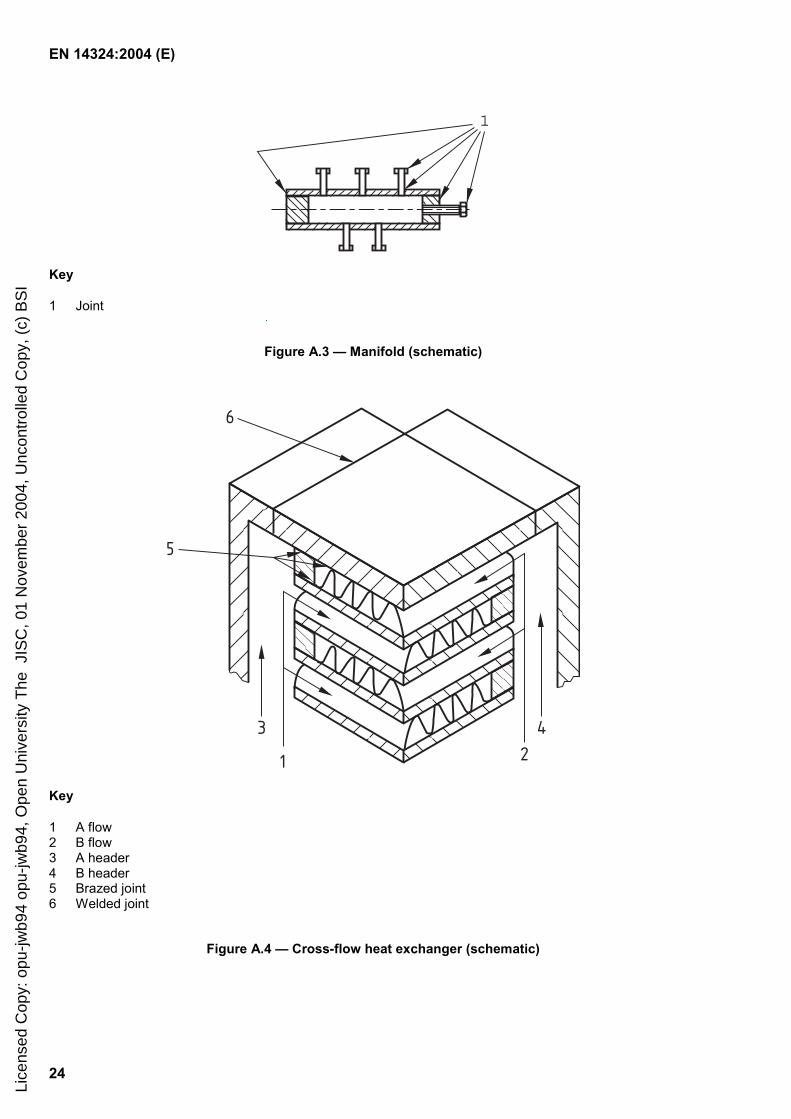
The figures in this annex illustrate examples of brazed assemblies. An electrical contact on a conductor (see Figure A.1) is one example, but more complicated assemblies may still have only a single joint, e.g. a flange on a pipe (see Figure A.2). However, one of the advantages of brazing is the ability to make several joints at the same time on an assembly such as a manifold (see Figure A.3). In addition, in some cases, with furnace brazing, it is possible to make very many joints at once as in a cross-flow heat exchanger that can be very large (see Figure A.4). In the case of metal-to-ceramic joints, cracking due to uneven thermal contraction can be a problem that can often be prevented by brazing a ceramic balance ring on the other side of the metal (see Figure A.5).
1
Key
1 Joint
Figure A.1 — Electrical contact on conductor (schematic)
1
Key
1 Joint
Figure A.2 — Flange on a pipe (schematic)
Lice
nsed
Cop
y: o
pu-jw
b94
opu-
jwb9
4, O
pen
Uni
vers
ity T
he J
ISC
, 01
Nov
embe
r 20
04, U
ncon
trol
led
Cop
y, (
c) B
SI
标准分享网 www.bzfxw.com 免费下载
EN 14324:2004 (E)
24
1
Key
1 Joint
Figure A.3 — Manifold (schematic)
6
5
3
1 24
Key
1 A flow 2 B flow 3 A header 4 B header 5 Brazed joint 6 Welded joint
Figure A.4 — Cross-flow heat exchanger (schematic)
Lice
nsed
Cop
y: o
pu-jw
b94
opu-
jwb9
4, O
pen
Uni
vers
ity T
he J
ISC
, 01
Nov
embe
r 20
04, U
ncon
trol
led
Cop
y, (
c) B
SI

EN 14324:2004 (E)
25
1
4
32
Key
1 Ceramic balance ring 2 Metal ring 3 Ceramic cylinder 4 Joint
Figure A.5 — Metal-to-ceramics (schematic)
Lice
nsed
Cop
y: o
pu-jw
b94
opu-
jwb9
4, O
pen
Uni
vers
ity T
he J
ISC
, 01
Nov
embe
r 20
04, U
ncon
trol
led
Cop
y, (
c) B
SI
标准分享网 www.bzfxw.com 免费下载
EN 14324:2004 (E)
26
Annex B (informative)
Typical examples of joint design
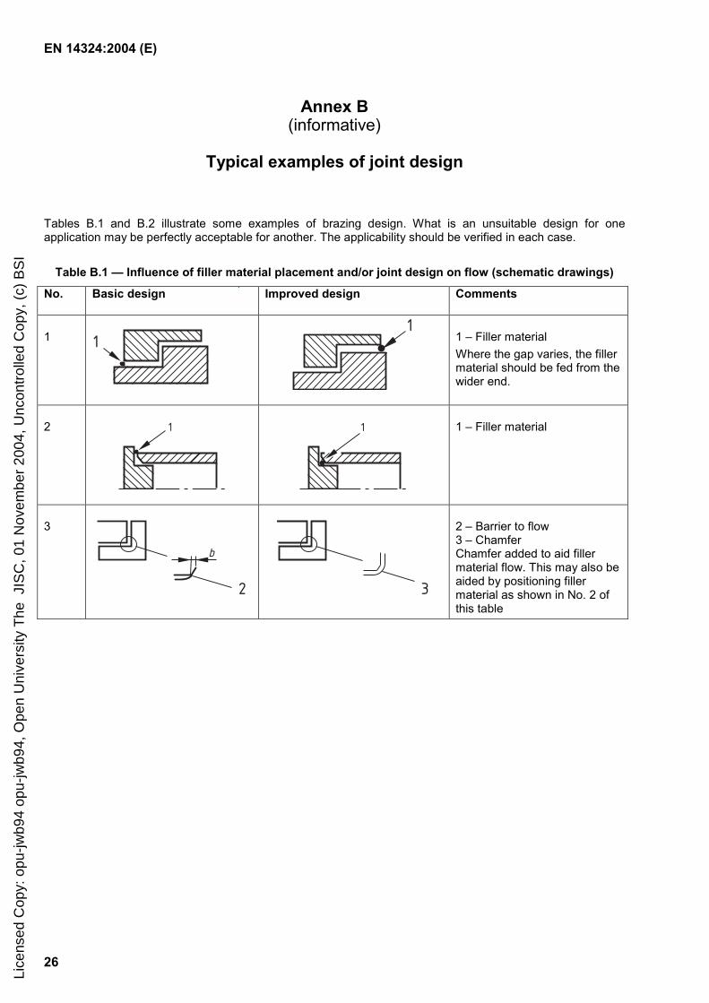
Tables B.1 and B.2 illustrate some examples of brazing design. What is an unsuitable design for one application may be perfectly acceptable for another. The applicability should be verified in each case.
Table B.1 — Influence of filler material placement and/or joint design on flow (schematic drawings)
No. Basic design Improved design Comments
1 1
1
1 – Filler material Where the gap varies, the filler material should be fed from the wider end.
2 1
1
1 – Filler material
3
b
2 3
2 – Barrier to flow 3 – Chamfer Chamfer added to aid filler material flow. This may also be aided by positioning filler material as shown in No. 2 of this table
Lice
nsed
Cop
y: o
pu-jw
b94
opu-
jwb9
4, O
pen
Uni
vers
ity T
he J
ISC
, 01
Nov
embe
r 20
04, U
ncon
trol
led
Cop
y, (
c) B
SI
EN 14324:2004 (E)
27
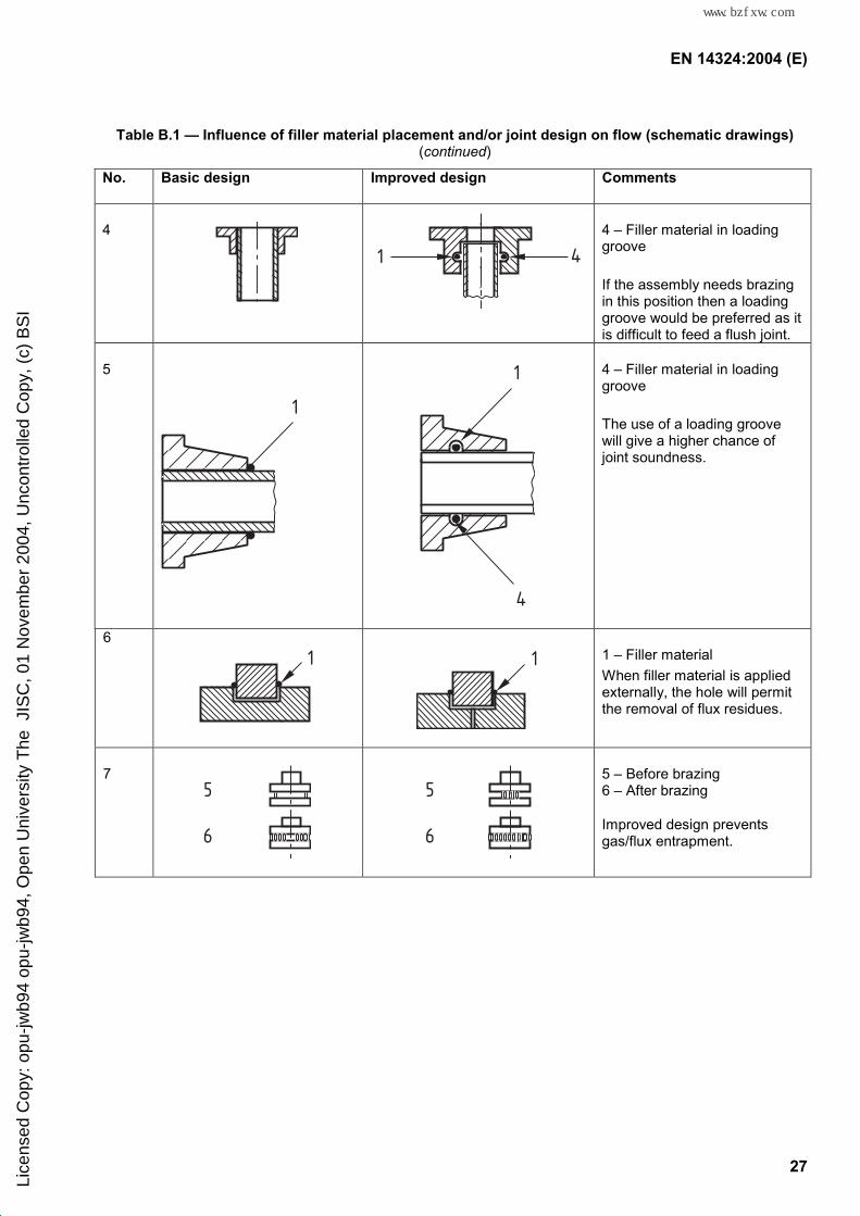
Table B.1 — Influence of filler material placement and/or joint design on flow (schematic drawings) (continued)
No. Basic design Improved design Comments
4
1 4
4 – Filler material in loading groove
If the assembly needs brazing in this position then a loading groove would be preferred as it is difficult to feed a flush joint.
5
1
1
4
4 – Filler material in loading groove
The use of a loading groove will give a higher chance of joint soundness.
6 1
1
1 – Filler material When filler material is applied externally, the hole will permit the removal of flux residues.
7 5
6
5
6
5 – Before brazing 6 – After brazing
Improved design prevents gas/flux entrapment.
Lice
nsed
Cop
y: o
pu-jw
b94
opu-
jwb9
4, O
pen
Uni
vers
ity T
he J
ISC
, 01
Nov
embe
r 20
04, U
ncon
trol
led
Cop
y, (
c) B
SI
标准分享网 www.bzfxw.com 免费下载
EN 14324:2004 (E)
28
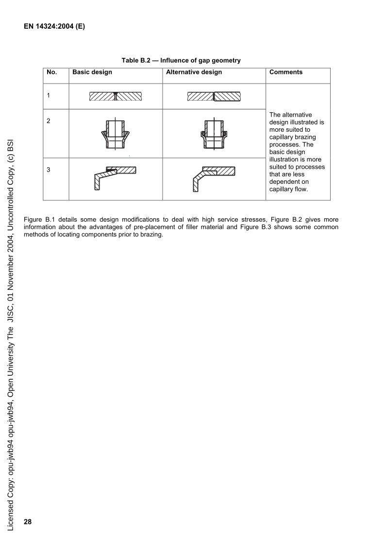
Table B.2 — Influence of gap geometry
No. Basic design Alternative design Comments
1
2
3
The alternative design illustrated is more suited to capillary brazing processes. The basic design illustration is more suited to processes that are less dependent on capillary flow.
Figure B.1 details some design modifications to deal with high service stresses, Figure B.2 gives more information about the advantages of pre-placement of filler material and Figure B.3 shows some common methods of locating components prior to brazing.
Lice
nsed
Cop
y: o
pu-jw
b94
opu-
jwb9
4, O
pen
Uni
vers
ity T
he J
ISC
, 01
Nov
embe
r 20
04, U
ncon
trol
led
Cop
y, (
c) B
SI

EN 14324:2004 (E)
29
Low stress High stress
Lap
Butt
Sheet
Sheet higher static and dynamic loading
Tube
Pipe
Axle
Figure B.1 — Design modifications to deal with high service stresses
Lice
nsed
Cop
y: o
pu-jw
b94
opu-
jwb9
4, O
pen
Uni
vers
ity T
he J
ISC
, 01
Nov
embe
r 20
04, U
ncon
trol
led
Cop
y, (
c) B
SI
标准分享网 www.bzfxw.com 免费下载
EN 14324:2004 (E)
30
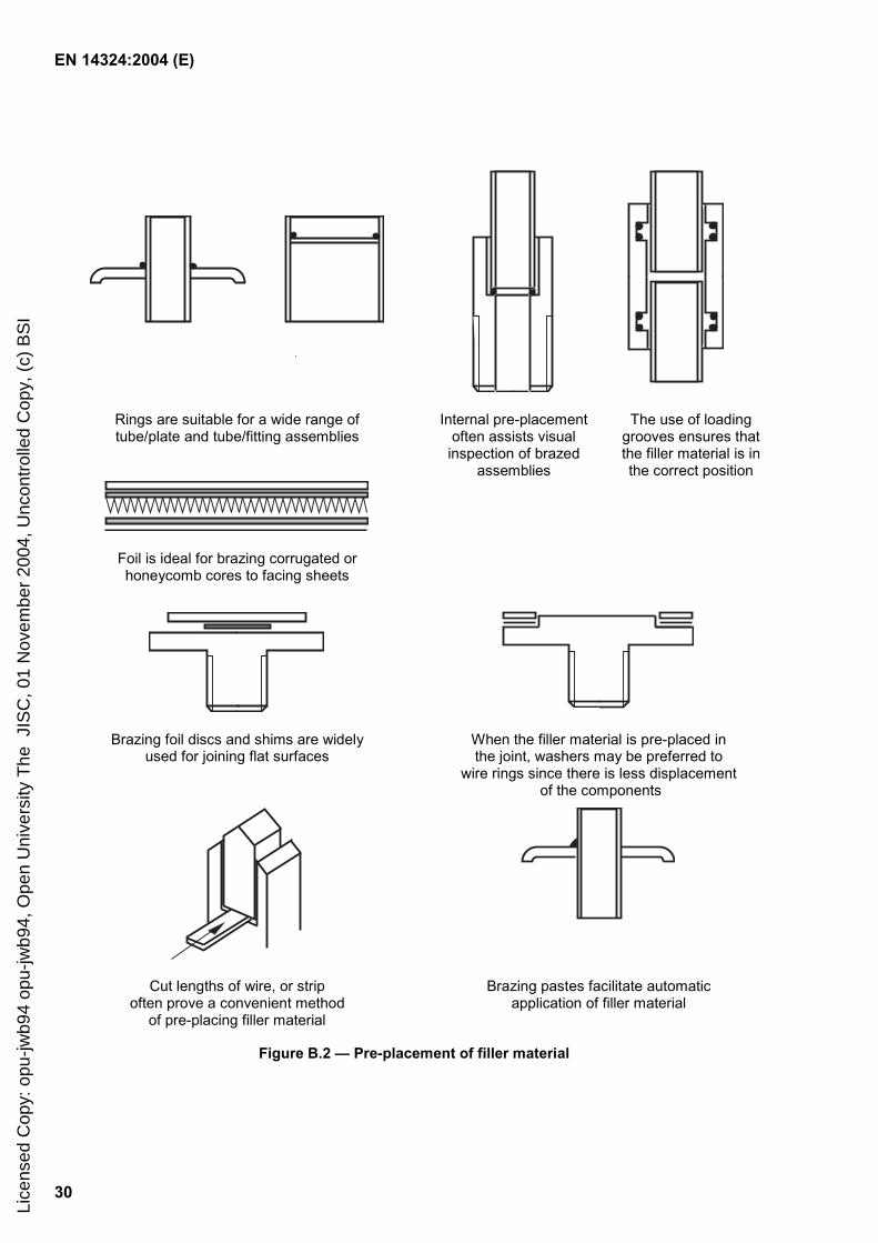
Rings are suitable for a wide range of tube/plate and tube/fitting assemblies
Internal pre-placement often assists visual inspection of brazed
assemblies
The use of loading grooves ensures that the filler material is in the correct position
Foil is ideal for brazing corrugated or honeycomb cores to facing sheets
Brazing foil discs and shims are widely used for joining flat surfaces
When the filler material is pre-placed in the joint, washers may be preferred to
wire rings since there is less displacement of the components
Cut lengths of wire, or strip often prove a convenient method
of pre-placing filler material
Brazing pastes facilitate automatic application of filler material
Figure B.2 — Pre-placement of filler material
Lice
nsed
Cop
y: o
pu-jw
b94
opu-
jwb9
4, O
pen
Uni
vers
ity T
he J
ISC
, 01
Nov
embe
r 20
04, U
ncon
trol
led
Cop
y, (
c) B
SI

EN 14324:2004 (E)
31
Punching Knurling
Resistance spot welding Arc tack welding
Riveting
Expanding Shoulder
Peening Screwing
Coining
Lack of Self - Self- location jigging locating
NOTE The required brazing gap is retained.
Figure B.3 — Common methods of locating components prior to brazing
Lice
nsed
Cop
y: o
pu-jw
b94
opu-
jwb9
4, O
pen
Uni
vers
ity T
he J
ISC
, 01
Nov
embe
r 20
04, U
ncon
trol
led
Cop
y, (
c) B
SI
标准分享网 www.bzfxw.com 免费下载
EN 14324:2004 (E)
32
Annex C (informative)
Filler materials most commonly used for combinations of parent
materials
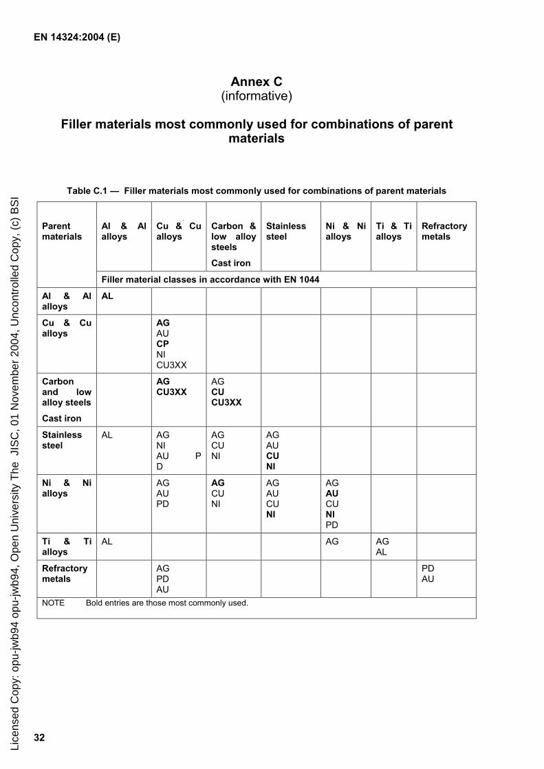
Table C.1 — Filler materials most commonly used for combinations of parent materials
Al & Al alloys
Cu & Cu alloys
Carbon & low alloy steels
Cast iron
Stainless steel
Ni & Ni alloys
Ti & Ti alloys
Refractory metals
Parent materials
Filler material classes in accordance with EN 1044
Al & Al alloys
AL
Cu & Cu alloys
AG AU CP NI CU3XX
Carbon and low alloy steels
Cast iron
AG CU3XX
AG CU CU3XX
Stainless steel
AL AG NI AU PD
AG CU NI
AG AU CU NI
Ni & Ni alloys
AG AU PD
AG CU NI
AG AU CU NI
AG AU CU NI PD
Ti & Ti alloys
AL AG AG AL
Refractory metals
AG PD AU
PD AU
NOTE Bold entries are those most commonly used.
Lice
nsed
Cop
y: o
pu-jw
b94
opu-
jwb9
4, O
pen
Uni
vers
ity T
he J
ISC
, 01
Nov
embe
r 20
04, U
ncon
trol
led
Cop
y, (
c) B
SI
EN 14324:2004 (E)
33
Annex D (informative)
Suitability of brazing filler material classes for the commoner brazing
methods
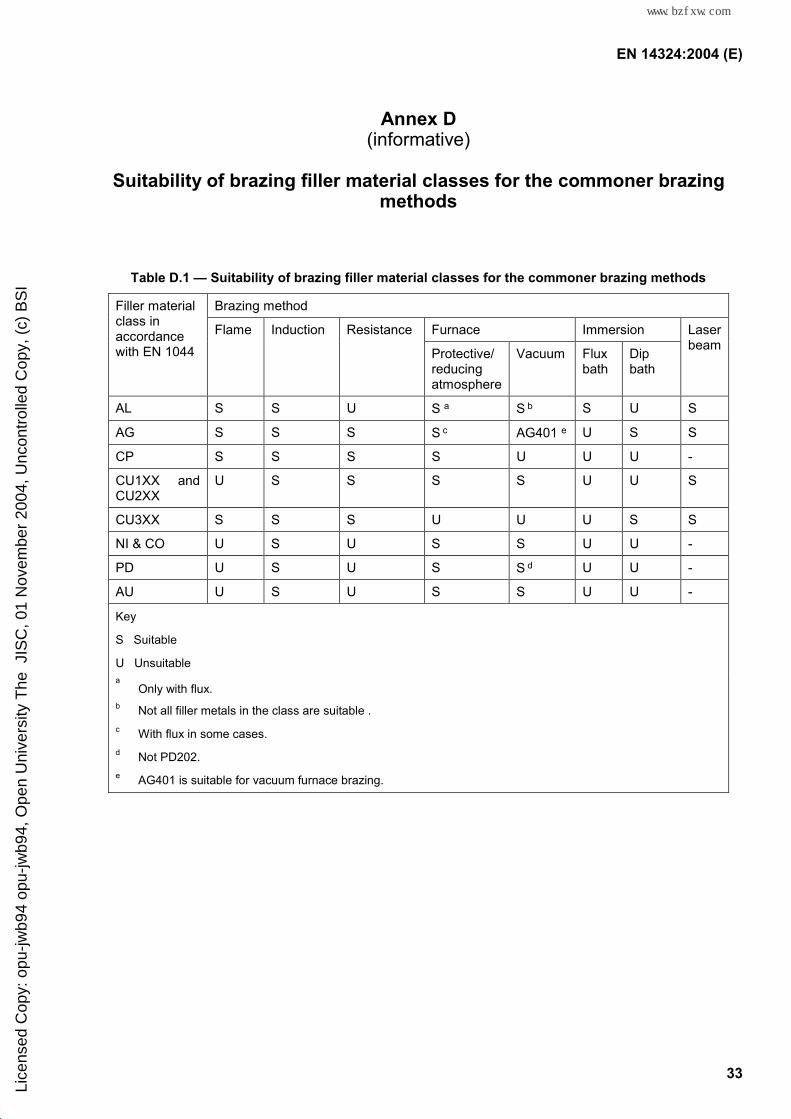
Table D.1 — Suitability of brazing filler material classes for the commoner brazing methods
Brazing method
Furnace Immersion
Filler material class in accordance with EN 1044
Flame Induction Resistance
Protective/ reducing atmosphere
Vacuum Flux bath
Dip bath
Laser beam
AL S S U S a S b S U S
AG S S S S c AG401 e U S S
CP S S S S U U U -
CU1XX and CU2XX
U S S S S U U S
CU3XX S S S U U U S S
NI & CO U S U S S U U -
PD U S U S S d U U -
AU U S U S S U U -
Key
S Suitable
U Unsuitable a Only with flux.
b Not all filler metals in the class are suitable . c With flux in some cases. d Not PD202. e AG401 is suitable for vacuum furnace brazing.
Lice
nsed
Cop
y: o
pu-jw
b94
opu-
jwb9
4, O
pen
Uni
vers
ity T
he J
ISC
, 01
Nov
embe
r 20
04, U
ncon
trol
led
Cop
y, (
c) B
SI
标准分享网 www.bzfxw.com 免费下载
EN 14324:2004 (E)
34
Annex E (informative)
Methods of brazing
E.1 Flame brazing
E.1.1 General
Various fuel gas mixtures may be used for flame brazing. The main factors affecting the choice of mixture are heating power, fuel and equipment investments and availability of gas supply.
The heating torch or blowpipe generally consists of either a single fuel gas delivery tube with adjustment valve and a port system to allow naturally aspirated air to mix with the fuel prior to combustion, or two delivery tubes, one supplying the fuel gas and the other the oxidant via adjustment valves and a pre-mixing chamber.
E.1.2 Hand torch brazing
E.1.2.1 Process
In this method the heat is generally applied using a single torch (blowpipe) held in the operator’s hand. For large work pieces multiple torches may be used.
In decreasing order of heating energy the gas systems generally employed are:
oxy-acetylene;
oxy-methyl acetylene mixtures (proprietary);
oxy-propane;
oxy-natural gas (methane);
compressed air-acetylene;
compressed air-propane;
compressed air-natural gas (methane);
aspirated air-acetylene and propane.
(Overlap occurs at the interface of the respective ranges.)
The choice of system will depend on many factors such as material melting temperature, manual skills available, production rate requirements, cost of fuel/oxidant combination, etc.
Lice
nsed
Cop
y: o
pu-jw
b94
opu-
jwb9
4, O
pen
Uni
vers
ity T
he J
ISC
, 01
Nov
embe
r 20
04, U
ncon
trol
led
Cop
y, (
c) B
SI

EN 14324:2004 (E)
35
E.1.2.2 Application
After adjustment to achieve optimum flame conditions and manipulation of the burner tip to concentrate heat at the optimum working distance (immediately outside the inner combustion cone) within the more massive of the component parts, flux can be applied dry by means of a hand held filler rod until the melting temperature is achieved and the rod is then normally allowed to dwell on the joint until fusion of the filler material occurs.
The process may however, with advantage, also be used with pre-placed paste-flux and filler material rings, or with brazing paste, or with self-fluxing brazing filler material.
Alternatively a gas flux can be added through the flame (flux processes). Clean and bright surfaces can be achieved and pickling is not necessary.
E.1.2.3 Advantages/limitations
The main advantages of the process are:
a) apparatus is simple and its operation is easily understood;
b) moderately rapid heating rate;
c) maximum flexibility of shape, size, heat pattern and consumables allowing simple and complex assembly operations;
d) minimum capital investment;
e) minimum maintenance.
Limitations of the process are:
1) high labour content (investment);
2) training is required to achieve consistent results;
3) relatively low production rate;
4) health and safety factors are more difficult to control.
E.1.2.4 Size limitations
The only limits imposed are the size of the available equipment and/or gas supply to deliver the required heating energy level and the means available for disposing of surplus energy and pollution (heat splash and fume).
E.1.2.5 Safety
Torches for hand torch brazing for fuel gas – oxygen and fuel gas – compressed air should be in accordance with EN ISO 5172. Fuel gas – aspirated air torches should be in accordance with EN 731.
Care has to be taken to operate the burner equipment and the gas installations strictly in accordance with the manufacturer’s instructions, because all fuel/gas oxidant mixtures are potentially explosive, as well as being fire hazards. No modifications or repairs may be carried out on the equipment other than by experts and trained personnel.
All hoses should be regularly checked for integrity, signs of chaffing and cracking and replaced as necessary.
Non-return valves and flashback arrestors should comply with EN 730-1 and EN 730-2.
Adequate ventilation should be ensured.
Lice
nsed
Cop
y: o
pu-jw
b94
opu-
jwb9
4, O
pen
Uni
vers
ity T
he J
ISC
, 01
Nov
embe
r 20
04, U
ncon
trol
led
Cop
y, (
c) B
SI
标准分享网 www.bzfxw.com 免费下载

EN 14324:2004 (E)
36
E.1.3 Mechanized flame brazing
E.1.3.1 Process
Assemblies to be brazed are presented in a jig, mounted on a trolley, rotary table or conveyor belt to a suitably designed burner system.
Burners with various profiles are available. They enable heat patterns to be designed to suit all assemblies of all shapes and sizes.
Various fuel gas mixtures are used for mechanized flame brazing. The main factors affecting the choice of mixture are heating power, fuel and equipment costs and availability of gas supply. In order of descending heating power, the typical gas mixtures used for mechanized flame brazing are:
oxy-acetylene;
oxy-propane;
compressed air-acetylene;
compressed air-propane;
compressed air-natural gas.
E.1.3.2 Application
The process is widely used for brazing at temperatures up to 1 000 °C and is applicable to all materials not adversely affected by heating in air.
Brazing fluxes which are necessary in all cases, other than the application of the self-fluxing copper-phosphorus based brazing filler materials to copper, can be applied manually by brushing or dipping, or automatically using specialized equipment.
Alternatively a gas flux can be added automatically through the flame. Clean and bright surfaces can be achieved and pickling is not necessary.
Brazing filler materials can be applied as hand-fed rod, but in mass production are normally applied either as a preform, or automatically as a paste, or wire. The filler materials generally used are as specified EN 1044:1999, Tables 3 and 4.
Lice
nsed
Cop
y: o
pu-jw
b94
opu-
jwb9
4, O
pen
Uni
vers
ity T
he J
ISC
, 01
Nov
embe
r 20
04, U
ncon
trol
led
Cop
y, (
c) B
SI
EN 14324:2004 (E)
37
E.1.3.3 Advantages/limitations
The main advantages of the process are:
a) moderate equipment investment;
b) simple maintenance;
c) high quantity;
d) flexibility regarding component shape and size and jigs;
e) suitable for continuous or indexing machines;
f) suitable for multiple joints that need to be made individually;
g) automatic feeding of filler materials, paste and flux.
Limitations of the process are:
1) heat input less rapid than induction heating;
2) local extraction of fumes hampered by velocity and volume of burnt gas;
3) not suitable brazing at high temperatures, e.g. above 1 000 °C;
4) complex assemblies subject to more distortion/local overheating than in a furnace;
5) more noise and heat dissipation compared with induction heating.
E.1.3.4 Size limitation
The only limits imposed are the size of the available equipment and/or gas supply to deliver the required heat energy level and the means available for disposing of surplus energy and pollution (heat splash and fume).
E.1.3.5 Safety
Adequate ventilation is necessary. It is essential that maintenance and modification of burners and gas supply is only carried out by competent personnel.
Fixed torches should always be lit from the side, or below, and not by reaching over an unlit torch to light another, since all burners in a system ignite simultaneously.
E.2 Induction brazing
E.2.1 Process
When alternating current is passed through a work-coil adjacent to or around a metal component, a secondary current is induced into the components, and heat is produced. When a high frequency (300 kHz) current is applied for heating steels the heat is concentrated at the surface; with a lower frequency (10 kHz) current a greater depth of penetration is achieved. Intermediate susceptors may be used to heat irregularly shaped components by radiation.
Lice
nsed
Cop
y: o
pu-jw
b94
opu-
jwb9
4, O
pen
Uni
vers
ity T
he J
ISC
, 01
Nov
embe
r 20
04, U
ncon
trol
led
Cop
y, (
c) B
SI
标准分享网 www.bzfxw.com 免费下载

EN 14324:2004 (E)
38
E.2.2 Application
The process can be used for brazing in all temperature ranges and on all electrically conducting materials. It is versatile and can be used either in ‘one-off’ operations or in equipment designed to mass produce components of the same shape. Either flux or controlled atmosphere can be used to aid the brazing process.
The filler material should be pre-placed, and the flux generally incorporated at the same time.
For high technology applications, the component may be processed in a vacuum or under the cover of a suitable gaseous atmosphere. For details regarding power sources, coil design, processes, and automation, manufacturers competent in the design and manufacture of suitable equipment should be consulted.
E.2.3 Advantages/limitations
The main advantages of the process are:
a) rapid heating;
b) closely controlled reproducible heat pattern for simple shapes;
c) economical to run;
d) the heat is concentrated in the joint areas.
Limitations of the process are:
1) high capital investment;
2) less efficient for materials which are non-ferromagnetic, particularly if of high thermal conductivity;
3) coil design is difficult for irregularly shaped or complex components.
E.2.4 Size limitations
In general, the method is used to heat only the area to be brazed and so, by careful design, very large assemblies can be brazed. At the other extreme of the size range, very small components can be processed by this method.
E.2.5 Safety
It is essential that care is taken when high frequency current is passed through the coil. Due to induction, metallic objects (including rings and watches), can be heated causing severe burns (not electric shock). Skin contact with the coil will also cause a r.f. burn. The manufacturer's instructions should be carefully observed and the equipment should be maintained, according to the manufacturer's instructions, by authorized personnel.
Adequate ventilation should be ensured.
Lice
nsed
Cop
y: o
pu-jw
b94
opu-
jwb9
4, O
pen
Uni
vers
ity T
he J
ISC
, 01
Nov
embe
r 20
04, U
ncon
trol
led
Cop
y, (
c) B
SI
EN 14324:2004 (E)
39
E.3 Resistance brazing
E.3.1 Process
The parts to be joined are raised to the brazing temperature by the passage of a high current at a low voltage. Suitably shaped electrodes are used to establish good electrical contact and to apply sufficient force to hold the component parts in the correct position for brazing. Heat may be generated indirectly within the body of the electrode (usually graphite) from where it is transmitted by thermal conduction to the joint assembly. Alternatively, heat may be generated directly by the combined effect of the various interfacial and bulk resistances of the parts themselves. In this case, water cooled metal electrodes of relatively high electrical conductivity are used to transmit current to, and maintain the appropriate holding force on, the joint assembly.
E.3.2 Application
The process is best suited to applications where joints of limited area and relatively simple geometry permit the ready access of electrodes to the assembly. It is particularly suitable for the repetitive brazing of flat symmetrical components using both manual and automated techniques.
Temperatures attained by the process vary according to the mode employed; indirect heating is usually restricted to temperatures below 800 °C, because of excessive burning and wastage of the graphite electrode, whereas such limitations do not apply to direct heating.
The use of flux in resistance brazing applications requires considerable care due to its non-conducting characteristics and the risk of explosion. In consequence, self-fluxing brazing filler materials are preferred or, less commonly, a localized protective atmosphere. Where the use of a flux cannot be avoided, a small quantity of thin paste (to be preferred) or liquid flux is employed.
E.3.3 Advantages/limitations
The main advantages of the process are:
a) extremely rapid localized heating;
b) low running investment;
c) low capital investment;
d) closely controlled reproducible heat pattern.
Limitations of the process are:
1) higher capital investment than hand torch brazing;
2) severe limitations on shape and size;
3) high wear of graphite electrodes;
4) potentially poor repeatability if flux is used;
5) not suitable for high temperature parent materials.
E.3.4 Size limitations
Energy requirements increase rapidly with increasing size of the joint, so restricting the use of the process to small joint areas.
Lice
nsed
Cop
y: o
pu-jw
b94
opu-
jwb9
4, O
pen
Uni
vers
ity T
he J
ISC
, 01
Nov
embe
r 20
04, U
ncon
trol
led
Cop
y, (
c) B
SI
标准分享网 www.bzfxw.com 免费下载
EN 14324:2004 (E)
40
E.3.5 Safety
Health hazards are limited to a spatter risk caused by dirty or high resistance parts, flux films or insufficient holding pressure. The time cycles are short and the volume of fume producing material small.
Adequate ventilation should be ensured.
E.4 Furnace brazing
E.4.1 Process variants
There are two main variants of the process; protective atmosphere or vacuum furnace brazing. The first can be continuous or batch operated. The second can generally only be batch operated. These variants are individually discussed in greater detail in E.4.2 to E.4.3, but certain aspects are common to all of them and are therefore considered in this sub-clause.
Many small components or one large one may occupy the available furnace space. It is essential to realise that the components are not accessible during brazing. Therefore, preparation before loading should include adequate jigging if the components are not self-aligning as well as the pre-placement of brazing filler material and (where relevant) flux. The joint should be designed to ensure correct positioning of the brazing filler material and its retention in the joint when molten. The process variables, e.g. heating and cooling rates, intermediate dwell and peak temperatures and times at temperature should be determined by preliminary trials and recorded in the procedure instructions. Since the brazing times are generally longer than with most other brazing processes, it is advisable to pay greater attention to the possible effects of the thermal cycle on the properties of the parent materials. Some advantages and limitations are also common to all furnace brazing processes as follows.
Advantages of the processes are:
a) minimal distortion, even on complex parts;
b) simultaneous brazing of multiple and/or multi-joint assemblies;
c) good control of process variables and therefore particularly suited to high integrity components.
Limitations of the processes are as follows:
1) through heating of the components is inevitable, which cannot be acceptable in some applications;
2) when the heating rates are slow, filler materials with wide melting ranges may be unsuitable because of liquation;
3) furnace contamination can occur from metallic vapours, metallic oxides or flux residues.
E.4.2 Protective atmosphere brazing
E.4.2.1 General
It is unusual to use flux in a protective atmosphere furnace as, to prevent oxidation, a suitable gas atmosphere is provided within the furnace.
The atmosphere most commonly used in a continuous furnace is exothermic, derived from partially burnt natural gas or propane, and is reducing. Cracked ammonia, hydrogen and nitrogen mixtures and endothermic atmospheres are also used. The selection of protecting gas, filler material and flux, if necessary, should be done taking the advice of the supplier of the filler material.
Lice
nsed
Cop
y: o
pu-jw
b94
opu-
jwb9
4, O
pen
Uni
vers
ity T
he J
ISC
, 01
Nov
embe
r 20
04, U
ncon
trol
led
Cop
y, (
c) B
SI
EN 14324:2004 (E)
41
E.4.2.2 Continuous furnace brazing
E.4.2.2.1 Process
Components are progressively conveyed through a continuously heated tunnel furnace, then through a cooling zone. The heating and cooling cycle depends upon the conveyor speed and temperature setting.
E.4.2.2.2 Application
Although applied to many materials, the major application of continuous heated furnace brazing is for the joining of mild steel with copper filler material.
It is important that the assemblies are secure and that parts are self-locating and will not be disturbed by the movement of the conveyor.
Conveyor speeds vary, according to the mass of components, giving typical process cycle times of 15 min to 2 h.
E.4.2.2.3 Advantages/limitations
The main advantages of the process are:
a) high production throughputs;
b) usually fluxless with no post-cleaning requirements;
c) components need not be as clean as for vacuum brazing;
d) can use low cost brazing filler materials.
Limitations of the process are:
1) high capital investment (but lower than vacuum furnaces per unit of output);
2) not practical to switch on and off repeatedly.
E.4.2.2.4 Size limitations
The maximum size of component is limited only by the furnace cross-sectional area.
E.4.2.2.5 Safety
Fumes need to be extracted. There is an explosion risk with highly reducing atmopheres, as with any hydrogen-rich gas.
E.4.2.3 Batch furnace brazing
E.4.2.3.1 Process
Components are loaded into a heated space, normally within a retort to hold the protective atmosphere.
The heating cycle is controlled by varying the furnace temperature. Rapid cooling is normally possible by removing the retort from the furnace.
Lice
nsed
Cop
y: o
pu-jw
b94
opu-
jwb9
4, O
pen
Uni
vers
ity T
he J
ISC
, 01
Nov
embe
r 20
04, U
ncon
trol
led
Cop
y, (
c) B
SI
标准分享网 www.bzfxw.com 免费下载

EN 14324:2004 (E)
42
E.4.2.3.2 Applications
Batch furnace brazing is principally used in the electronic and electrical industries.
E.4.2.3.3 Advantages/limitations
The main advantages of the process are:
a) usually fluxless with no post-cleaning requirements;
b) components generally need not to be as clean as for vacuum brazing;
c) larger components can be processed than in a continuous furnace.
Limitations of the process are:
1) long cycle time;
2) limited retort life at higher temperatures;
3) high energy consumption.
E.4.2.3.4 Size limitations
Large components can be processed.
E.4.2.3.5 Safety
Fumes need to be extracted. There is an explosion risk with highly reducing atmospheres as with any hydrogen-rich gas.
E.4.3 Vacuum brazing
E.4.3.1 Process
The furnace has a chamber (usually water cooled), with a sealable door, inside which are heat shields. The furnace is heated by resistance heaters on the inner faces of the heat shields.
The furnace is continually pumped during heating, normally to pressures of the order of 1 x 10⁻³ mbar to 1 x 10⁻⁵ mbar and this removes any evolved gases. Other pressure ranges may be specified for special purposes. The function of the vacuum is to preserve surface cleanliness and permit filler material flow. Low leakage rates are as important as pumping speed and ultimate pressure.
Accurate means of regulating temperature, heating and cooling rates are normally available. To speed cooling after brazing, provision is made to circulate through the furnace cooled gas that is inert to the materials being brazed.
E.4.3.2 Application
Although in principle widely applicable, vacuum brazing is normally used for brazing at high temperature of the corrosion and heat resisting types of alloys.
Heating is slow and this results in total floor-to-floor cycle times in the range 2 h to 10 h.
Lice
nsed
Cop
y: o
pu-jw
b94
opu-
jwb9
4, O
pen
Uni
vers
ity T
he J
ISC
, 01
Nov
embe
r 20
04, U
ncon
trol
led
Cop
y, (
c) B
SI
EN 14324:2004 (E)
43
E.4.3.3 Advantages/limitations
The main advantages of the process are:
a) high alloy steels, nickel alloys containing titanium and aluminium and reactive metals can be brazed;
b) flux-free brazing with no post-braze cleaning required;
c) precise heating cycles and thermal control;
d) brazing combined with heat treatment of parent materials to be joined.
Limitations of the process are:
1) high capital investment;
2) surfaces of components have to be clean (more critical than with other processes);
3) heating and cooling rates may be slower than optimum for certain materials;
4) it is essential that volatile metals are excluded from the furnace charge (except when brazing aluminium).
E.4.3.4 Size limitations
Production furnaces with ruling dimensions of 300 mm to 1 000 mm are common, but larger furnaces are available.
E.4.3.5 Safety
There are few hazards except from residual backfill gases in larger furnaces.
Adequate ventilation should be ensured.
E.5 Immersion brazing
E.5.1 General
The assembly is raised to the brazing temperature by partial or total immersion in a molten heat transfer medium. Three types of process are used:
a) flux bath brazing;
b) dip bath brazing;
c) salt bath brazing.
E.5.2 Flux bath brazing
E.5.2.1 Process
Flux bath brazing (also known as flux dip brazing) is the most widely used and involves the submersion of the components in a bath of suitably active molten flux. Filler material preforms are placed adjacent to the joint area prior to immersion.
Lice
nsed
Cop
y: o
pu-jw
b94
opu-
jwb9
4, O
pen
Uni
vers
ity T
he J
ISC
, 01
Nov
embe
r 20
04, U
ncon
trol
led
Cop
y, (
c) B
SI
标准分享网 www.bzfxw.com 免费下载

EN 14324:2004 (E)
44
E.5.2.2 Application
The process is restricted to the brazing of aluminium and a limited range of aluminium alloys over a relatively narrow range of temperatures around 600 °C. The technique is particularly suitable for the simultaneous brazing of multiple joints in complex assemblies such as heat exchangers.
E.5.2.3 Advantages/limitations
The main advantages of the process are:
a) provides precise and even heating of complex assemblies;
b) simultaneous heat treatment can be carried out.
Limitations of the process are:
1) need for careful preheating;
2) need for control of flux bath composition;
3) provision needs to be made for flux access and drainage;
4) need for meticulous removal of corrosive flux residues;
5) tendency for distortion of parts heated close to their melting temperature.
E.5.2.4 Size limitations
Flux bath brazing will accommodate a wide range of sizes including thin sections. The maximum dimension which can be handled will depend on the flux bath size but may be of the order of 1 m.
E.5.2.5 Safety
There is a significant risk of explosion if pre-heating is not carried out efficiently. Irritant fumes are emitted by the molten flux and require adequate extraction. Splashing by molten flux is an ever present risk.
E.5.3 Dip bath brazing
E.5.3.1 Process
Dip bath brazing involves immersion of the immediate joint area in a molten filler material bath, the surface of which is usually protected by a layer of molten flux. This process is mainly restricted to the joining of the ends of light section assemblies of limited heat capacity.
E.5.3.2 Application
Filler materials with melting temperatures in excess of 900 °C are seldom used and operating temperatures are usually below 750 °C due to problems of limited flux stability at operating temperatures. For wire terminations and junctions of appropriate geometry it offers a rapid means of achieving high integrity joints.
Lice
nsed
Cop
y: o
pu-jw
b94
opu-
jwb9
4, O
pen
Uni
vers
ity T
he J
ISC
, 01
Nov
embe
r 20
04, U
ncon
trol
led
Cop
y, (
c) B
SI
EN 14324:2004 (E)
45
E.5.3.3 Advantages/limitations
The main advantages of the process are:
a) wide brazing gaps can be accommodated;
b) good standard of joint;
c) rapid heat transfer.
Limitations of the process are:
1) compositional drift of the bath which needs to be monitored;
2) need for frequent flux replenishment;
3) need to preheat components;
4) surfaces of components are coated with brazing filler material which is wasteful.
E.5.3.4 Size limitations
Components brazed by the process will seldom exceed 5 mm in cross section and a few centimetres in length due to the chilling effect of more massive parts.
E.5.3.5 Safety
With this process, the risks are as follows:
explosion with damp assemblies;
splashing of molten metal and flux;
evolution of toxic metal oxide.
Cadmium-bearing AG series filler materials and their associated fluxes are the most hazardous combination in this last respect.
Adequate ventilation should be ensured.
E.5.4 Salt bath brazing
E.5.4.1 Process
Now largely outmoded, this process involves submerging the assembly to be brazed in a fused salt bath. Brazing filler material preform and a suitable brazing flux are applied to the joint area prior to immersion.
E.5.4.2 Application
Application is restricted to ferrous components where brazing and heat treatment may often be combined in a single operation. In this case only those EN 1044, AG and CU3XX filler materials with melting temperatures in excess of 750 °C will be suitable.
Lice
nsed
Cop
y: o
pu-jw
b94
opu-
jwb9
4, O
pen
Uni
vers
ity T
he J
ISC
, 01
Nov
embe
r 20
04, U
ncon
trol
led
Cop
y, (
c) B
SI
标准分享网 www.bzfxw.com 免费下载

EN 14324:2004 (E)
46
E.5.4.3 Advantages/limitations
The main advantages of the process are:
a) uniform temperatures and rapid heating rate;
b) components remain scale free;
c) combined heat treatment and brazing operations are possible.
Limitations of the process are:
1) need to preheat to dry flux;
2) not suitable for light section parts due to floatation surface tension effects of salt;
3) salt removal and its safe disposal cause problems.
E.5.4.4 Size limitations
It is not a practical process for small parts of low mass. Maximum dimensions are limited only by the size of salt bath available.
E.5.4.5 Safety
Health hazards emanate largely from the molten salt and include the danger of explosion from damp components, splashing by molten salts and fumes emanating from the bath surface.
Adequate ventilation should be ensured.
E.6 Special methods
E.6.1 Laser beam brazing
E.6.1.1 Process
A continuous wave laser beam is used as the heat source. With a defocused beam it is possible to heat the pre-placed or automatically fed brazing filler material to its melting temperature as well as heating the joint surfaces of the components to a temperature sufficiently high for localized filler material wetting and flow to occur. The laser beam is absorbed in the top surface of the joint only. The variables for the process are the power of the laser beam, focussing, traverse and details of wire supply.
E.6.1.2 Application
The process is suitable for components that require a minimal or a very localized amount of heat input to the joint.
Lice
nsed
Cop
y: o
pu-jw
b94
opu-
jwb9
4, O
pen
Uni
vers
ity T
he J
ISC
, 01
Nov
embe
r 20
04, U
ncon
trol
led
Cop
y, (
c) B
SI

EN 14324:2004 (E)
47
E.6.1.3 Advantages/limitations
The main advantages of the process are:
a) localized heat source;
b) suitable for sealing joints where uniform heating of the whole joint is impractical.
Limitations of the process are:
1) only for thin sheets;
2) high capital cost;
3) limited capillary flow;
4) for some metals, e.g. copper, beam reflection can cause operating difficulties;
5) impractical to switch on and off repeatedly.
E.6.1.4 Safety
As for all laser applications, the safety rules for this type of equipment have to be followed. It should only be used by competent personnel.
E.6.2 Brazing/braze welding with an arc
E.6.2.1 Process
Arc brazing/braze welding processes can be divided into gas-shielded metal arc (MIG) and tungsten inert gas (TIG) brazing/braze welding.
The principle of brazing/braze welding with an electric arc is mainly similar to MIG and plasma arc welding with wire consumables. Copper alloy filler materials are used.
E.6.2.2 Application
This process is suitable for surface coated or uncoated thin sheet, e.g. galvanized sheet.
E.6.2.3 Advantages/limitations
The main advantages of the process are:
a) reduced damage of the coating and a lower thermal load can be achieved because of the lower melting temperature of the filler materials;
b) the filler materials used are largely corrosion resistant;
c) there is no important melting of the parent materials;
d) working under local shielding gas atmospheres and without fluxes.
Limitations of the process are:
1) joint has to be accessible for shielded gas torch (plasma gas torch);
2) thickness of sheet usually up to 3 mm.
E.6.2.4 Safety
Adequate ventilation should be ensured. If necessary, torches with localized ventilation should be used.
With this process metal vapour and dust can be generated. All safety regulations should be observed.
E.6.3 Other methods Other methods are possible, e.g. infra-red brazing and electron beam brazing, which are better described as braze welding.
Lice
nsed
Cop
y: o
pu-jw
b94
opu-
jwb9
4, O
pen
Uni
vers
ity T
he J
ISC
, 01
Nov
embe
r 20
04, U
ncon
trol
led
Cop
y, (
c) B
SI
标准分享网 www.bzfxw.com 免费下载
EN 14324:2004 (E)
48
Bibliography
[1] EN 730-1, Gas welding equipment — Safety devices — Part 1: Incorporating a flame (flashback) arrestor.
[2] EN 730-2, Gas welding equipment — Safety devices — Part 2: Not incorporating a flame (flashback) arrestor.
[3] EN 731, Gas welding equipment — Air-aspirated hand blowpipes — Specifications and tests.
[4] EN ISO 5172, Manual blowpipes for welding, cutting and heating — Specifications and tests (ISO 5172:1995, including Amendment 1:1995).
Lice
nsed
Cop
y: o
pu-jw
b94
opu-
jwb9
4, O
pen
Uni
vers
ity T
he J
ISC
, 01
Nov
embe
r 20
04, U
ncon
trol
led
Cop
y, (
c) B
SI

blankLice
nsed
Cop
y: o
pu-jw
b94
opu-
jwb9
4, O
pen
Uni
vers
ity T
he J
ISC
, 01
Nov
embe
r 20
04, U
ncon
trol
led
Cop
y, (
c) B
SI
标准分享网 www.bzfxw.com 免费下载
BS EN 14324:2004
BSI
389 Chiswick High Road
London
W4 4AL
BSI — British Standards InstitutionBSI is the independent national body responsible for preparing British Standards. It presents the UK view on standards in Europe and at the international level. It is incorporated by Royal Charter.
Revisions
British Standards are updated by amendment or revision. Users of British Standards should make sure that they possess the latest amendments or editions.
It is the constant aim of BSI to improve the quality of our products and services. We would be grateful if anyone finding an inaccuracy or ambiguity while using this British Standard would inform the Secretary of the technical committee responsible, the identity of which can be found on the inside front cover. Tel: +44 (0)20 8996 9000. Fax: +44 (0)20 8996 7400.
BSI offers members an individual updating service called PLUS which ensures that subscribers automatically receive the latest editions of standards.
Buying standards
Orders for all BSI, international and foreign standards publications should be addressed to Customer Services. Tel: +44 (0)20 8996 9001. Fax: +44 (0)20 8996 7001. Email: [email protected]. Standards are also available from the BSI website at http://www.bsi-global.com.
In response to orders for international standards, it is BSI policy to supply the BSI implementation of those that have been published as British Standards, unless otherwise requested.
Information on standards
BSI provides a wide range of information on national, European and international standards through its Library and its Technical Help to Exporters Service. Various BSI electronic information services are also available which give details on all its products and services. Contact the Information Centre. Tel: +44 (0)20 8996 7111. Fax: +44 (0)20 8996 7048. Email: [email protected].
Subscribing members of BSI are kept up to date with standards developments and receive substantial discounts on the purchase price of standards. For details of these and other benefits contact Membership Administration. Tel: +44 (0)20 8996 7002. Fax: +44 (0)20 8996 7001. Email: [email protected].
Information regarding online access to British Standards via British Standards Online can be found at http://www.bsi-global.com/bsonline.
Further information about BSI is available on the BSI website at http://www.bsi-global.com.
Copyright
Copyright subsists in all BSI publications. BSI also holds the copyright, in the UK, of the publications of the international standardization bodies. Except as permitted under the Copyright, Designs and Patents Act 1988 no extract may be reproduced, stored in a retrieval system or transmitted in any form or by any means – electronic, photocopying, recording or otherwise – without prior written permission from BSI.
This does not preclude the free use, in the course of implementing the standard, of necessary details such as symbols, and size, type or grade designations. If these details are to be used for any other purpose than implementation then the prior written permission of BSI must be obtained.
Details and advice can be obtained from the Copyright & Licensing Manager. Tel: +44 (0)20 8996 7070. Fax: +44 (0)20 8996 7553. Email: [email protected].
Lice
nsed
Cop
y: o
pu-jw
b94
opu-
jwb9
4, O
pen
Uni
vers
ity T
he J
ISC
, 01
Nov
embe
r 20
04, U
ncon
trol
led
Cop
y, (
c) B
SI


![[RTF] ‡准号 标 准 名 称 A36/A36M 碳素结构钢 A131/A131M 船用结构钢 ... .5.1.1 补焊修整应根据焊接工艺规范(WPS),使用有保护电弧焊(SMAW)、气体保护电弧焊(GMAW)、药芯焊丝电弧焊(FCAW)或埋弧焊(SAW](https://static.fdocument.pub/doc/165x107/5b37521d7f8b9a4a728bf2c9/rtf-a36a36m-a131a131m-.jpg)
