Lecture 2: examples of rigid body kinematics 2: examples of rigid body kinematics • forward...
23
Lecture 2: examples of rigid body kinematics • forward kinematics problem • head impact demo • rolling disk • intro to project #3 Tuesday, April 9, 13
-
Upload
phungxuyen -
Category
Documents
-
view
222 -
download
1
Transcript of Lecture 2: examples of rigid body kinematics 2: examples of rigid body kinematics • forward...
Lecture 2: examples of rigid body kinematics
• forward kinematics problem• head impact demo• rolling disk• intro to project #3
Tuesday, April 9, 13

robotic arm• Forward Kinematics: prescribe motion of
links AB & BC, calculate motion of C
http://www.nytimes.com/2012/05/26/science/space/space-x-capsule-docks-at-space-station.html?_r=0
j
kiθ1
θ2
Α
B
C
↵AB = ↵BC = Asin(⇡t)rC =vC =
Given:Find:
Tuesday, April 9, 13
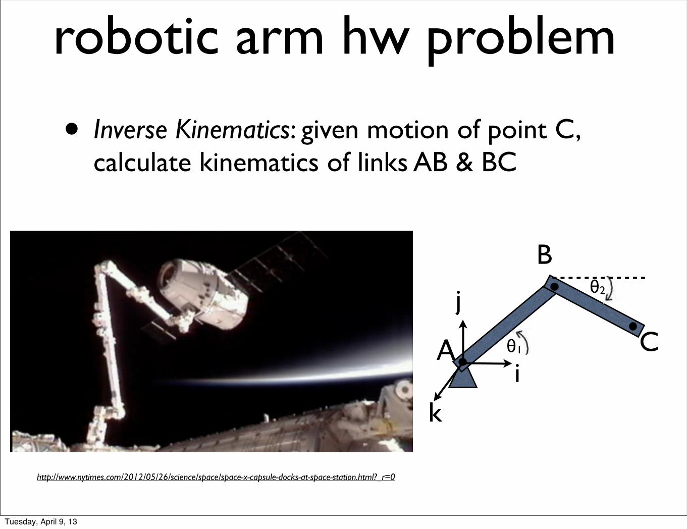
robotic arm hw problem
• Inverse Kinematics: given motion of point C, calculate kinematics of links AB & BC
http://www.nytimes.com/2012/05/26/science/space/space-x-capsule-docks-at-space-station.html?_r=0
j
kiθ1
θ2
Α
B
C
Tuesday, April 9, 13

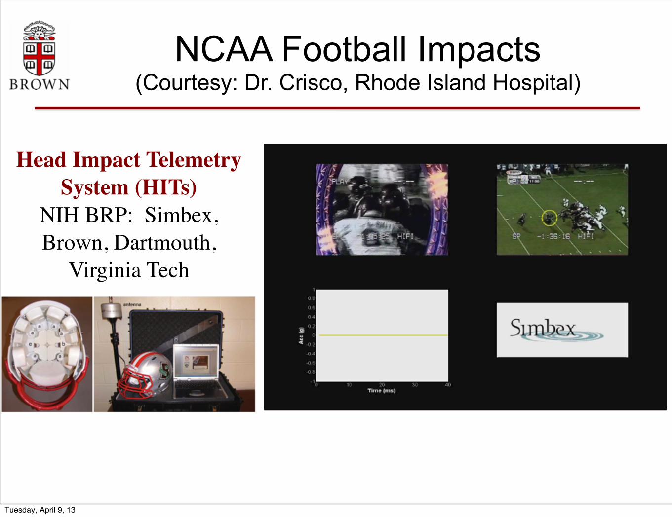
NCAA Football Impacts (Courtesy: Dr. Crisco, Rhode Island Hospital)
Head Impact Telemetry System (HITs)
NIH BRP: Simbex, Brown, Dartmouth,
Virginia Tech
Tuesday, April 9, 13
NCAA Football Impacts (Courtesy: Dr. Crisco, Rhode Island Hospital)
Head Impact Telemetry System (HITs)
NIH BRP: Simbex, Brown, Dartmouth,
Virginia Tech
Tuesday, April 9, 13
y""
x""
z""
F"
CM"r1""
aCM"
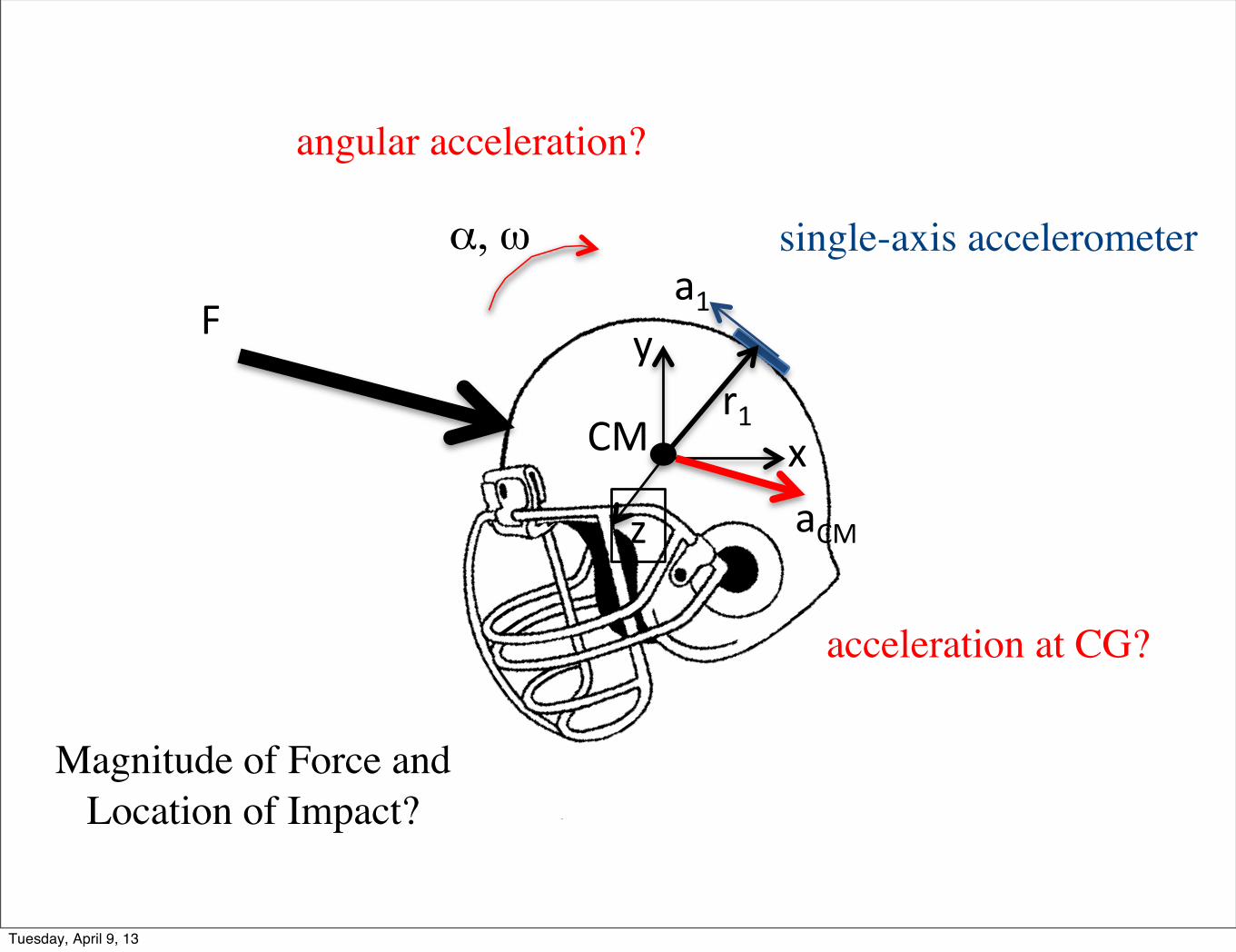
a1"α, ω# single-axis accelerometer
acceleration at CG?
angular acceleration?
Magnitude of Force and Location of Impact?
Tuesday, April 9, 13
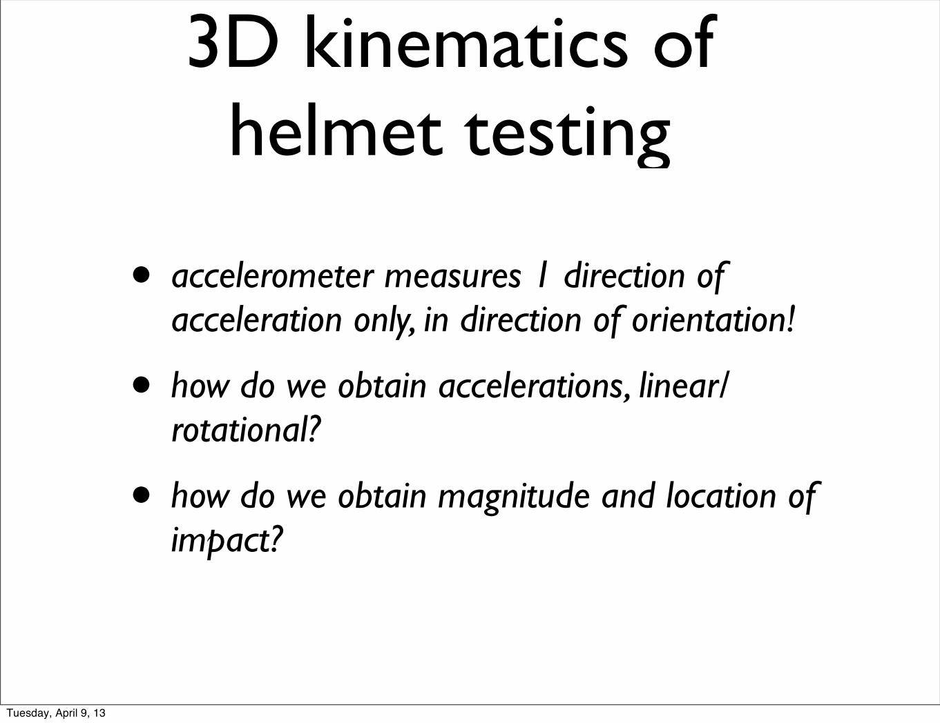
• accelerometer measures 1 direction of acceleration only, in direction of orientation!
• how do we obtain accelerations, linear/rotational?
• how do we obtain magnitude and location of impact?
3D kinematics of helmet testing
Tuesday, April 9, 13

Rolling Disk (no slip)
O O’
C
C’θ
Tuesday, April 9, 13
Rolling Disk (no slip)
O O’
C
C’θ
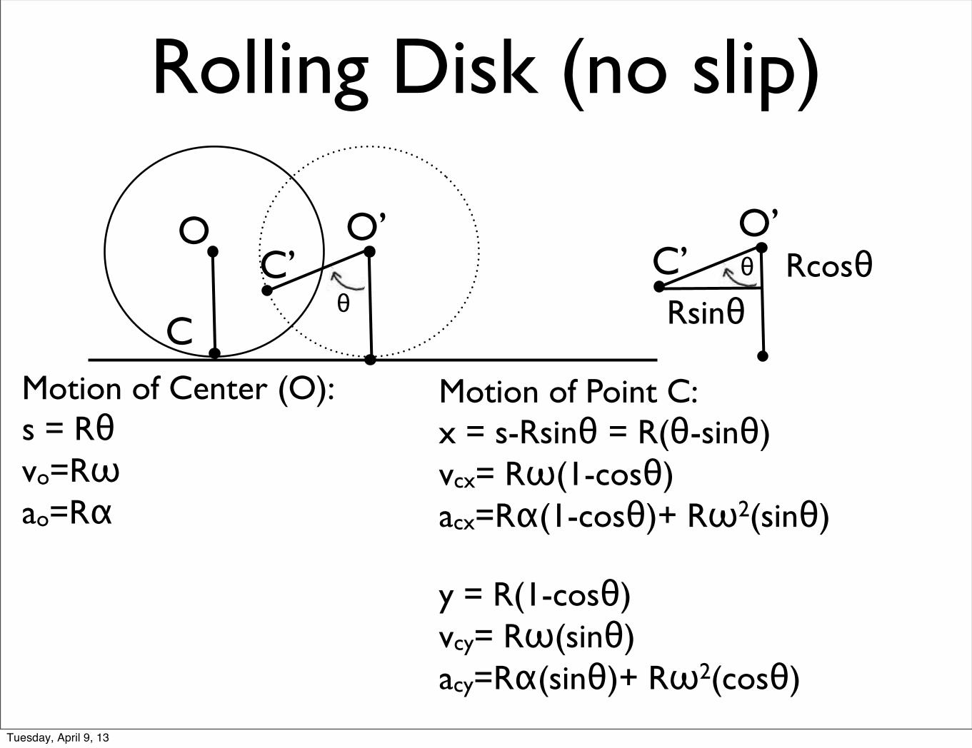
O’C’ θ RcosθRsinθ
Motion of Center (O):s = Rθvo=Rωao=Rα
Motion of Point C:x = s-Rsinθ = R(θ-sinθ)vcx= Rω(1-cosθ)acx=Rα(1-cosθ)+ Rω2(sinθ)
y = R(1-cosθ)vcy= Rω(sinθ)acy=Rα(sinθ)+ Rω2(cosθ)
Tuesday, April 9, 13
Rolling Disk (no slip)
O O’
C
C’θ
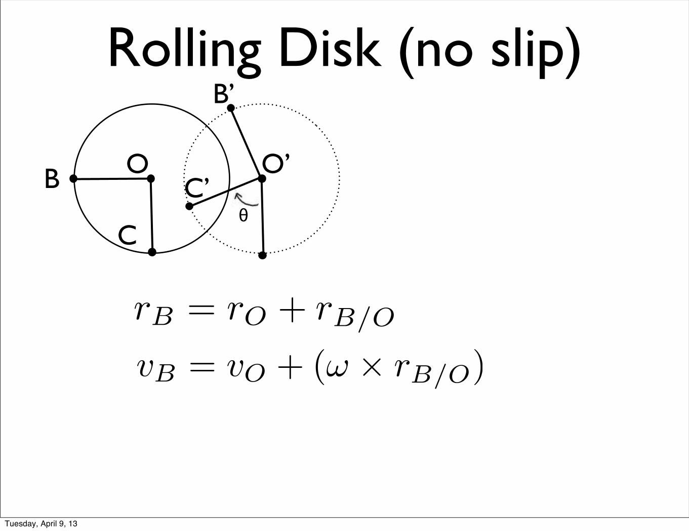
rB = rO + rB/O
B
vB = vO + (! ⇥ rB/O)
B’
Tuesday, April 9, 13
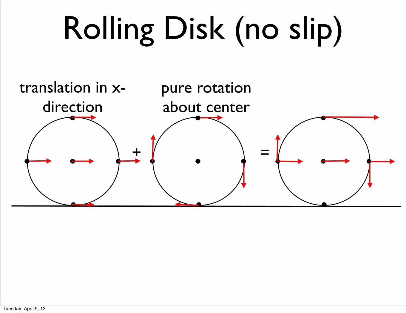
+ =
Rolling Disk (no slip)
translation in x-direction
pure rotation about center
Tuesday, April 9, 13

EN40 Dynamics and Vibra2onsProject # 3
A Trifilar Pendulum to Measure Mass Moments of Iner2a
• What is a Trifilar Pendulum?
• A plaForm hanging by 3 cables that can support an “object”• If we perturb the pendulum by a small angle, it will oscillate (spin) at a certain frequency• The frequency depends on the mass moment of inter2a
Tuesday, April 9, 13

(i) Derive the formula that relates the vibra2on frequency to the mass moment of iner2a
(ii) Design the pendulum (choose the dimensions, geometry, mass, etc)
(iii) Construct the pendulum (iv) Test the accuracy of the design (v) Use the device to measure the mass moment
of iner2a of several objects of complex shapes
Your Tasks:
Tuesday, April 9, 13

Project Schedule
• April 9 (TODAY!): Start analysis of Trifilar Pendulum (part of HW7) • April 9: Form teams of three students or fewer• April 12: Submit HW7 (KEEP A COPY) • Week of April 15: ConstrucNon and tesNng • April 19: Final design tesNng; report due.
Tuesday, April 9, 13
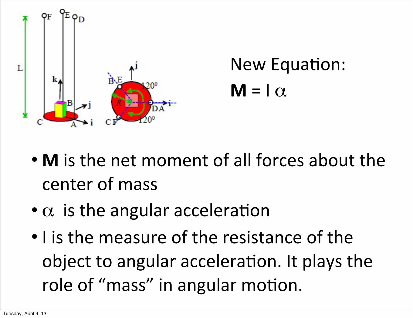
•M is the net moment of all forces about the center of mass• α is the angular accelera2on• I is the measure of the resistance of the object to angular accelera2on. It plays the role of “mass” in angular mo2on.
New Equa2on: M = I α
Tuesday, April 9, 13

• For a rigid body, measuring I is as important as measuring its mass!
• I depends on the mass and shape of the body. Can be easily calculated for simple geometries (sphere, prism, etc.) of uniform density
• Complex geometries: easier to measure!
I=mass moment of iner2a
Tuesday, April 9, 13
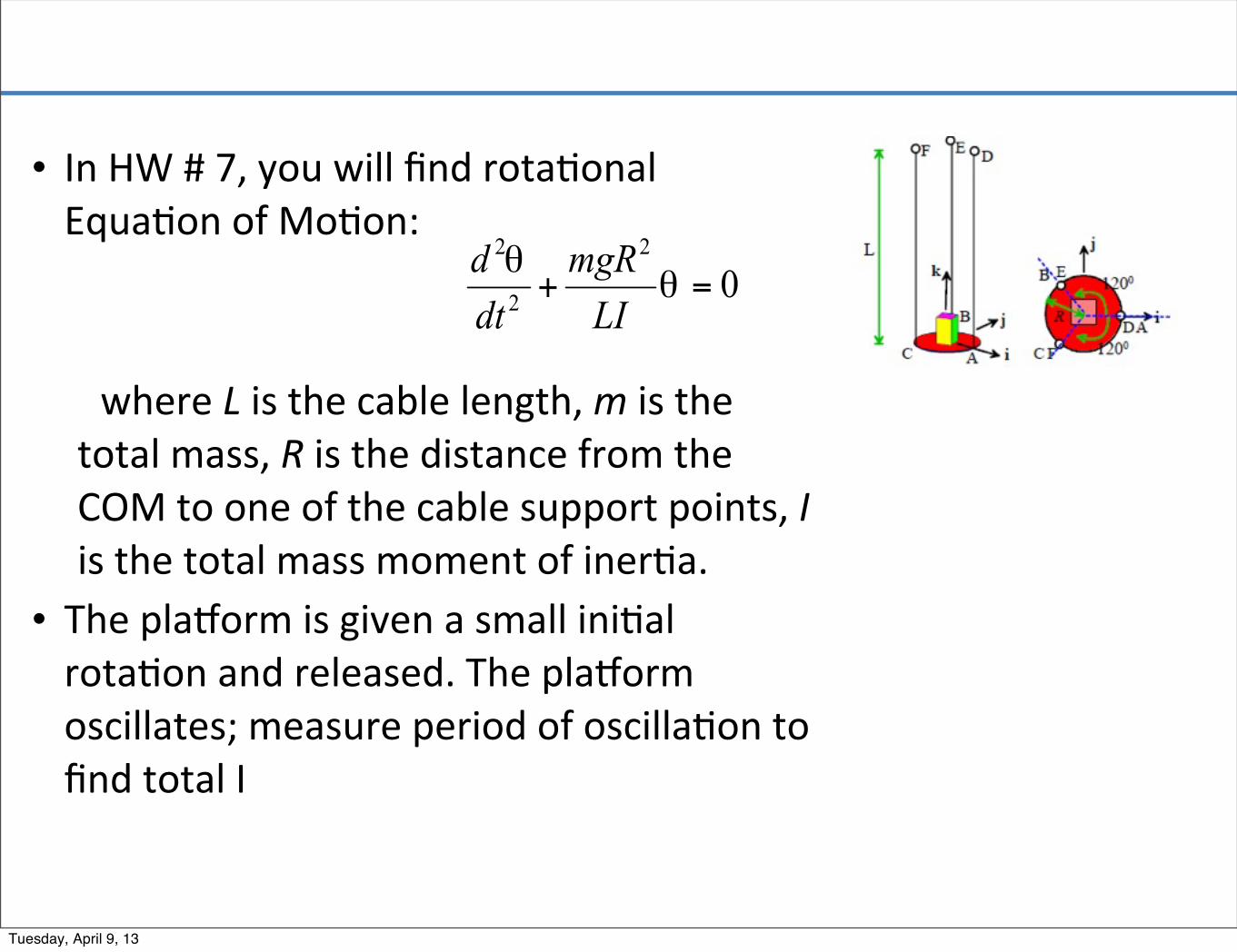
• In HW # 7, you will find rota2onal Equa2on of Mo2on:
where L is the cable length, m is the total mass, R is the distance from the COM to one of the cable support points, I is the total mass moment of iner2a.
• The plaForm is given a small ini2al rota2on and released. The plaForm oscillates; measure period of oscilla2on to find total I
Tuesday, April 9, 13
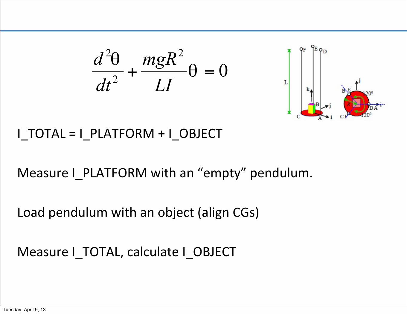
I_TOTAL = I_PLATFORM + I_OBJECT
Measure I_PLATFORM with an “empty” pendulum.
Load pendulum with an object (align CGs)
Measure I_TOTAL, calculate I_OBJECT
Tuesday, April 9, 13
Design Considera2ons
• You must make sure you can measure the period of the system sufficiently accurately. Eg. Make sure that you don’t need to measure the ;me period with 0.0001s accuracy in order to measure the moment of iner;a (MOI). You should be able to use a stop watch and get sufficient accuracy.
• You must make the device sensi;ve to the object of interest. For example, the ;me period should be sufficiently different with and without the object, so that you can accurately dis;nguish between IplaForm and IplaForm+Iobject.
• Addi;onal design considera;ons: (i) Accuracy of alignment of CM, for both plaNorm and objects of
interest. (ii) Mass and size range of objects to study (iii) Support of various shapes (iv) Robustness of design• Your en;re device will include the cables and a top support structure. During tes;ng, this support structure will be clamped to another fixed plaNorm in Prince Lab.
Tuesday, April 9, 13
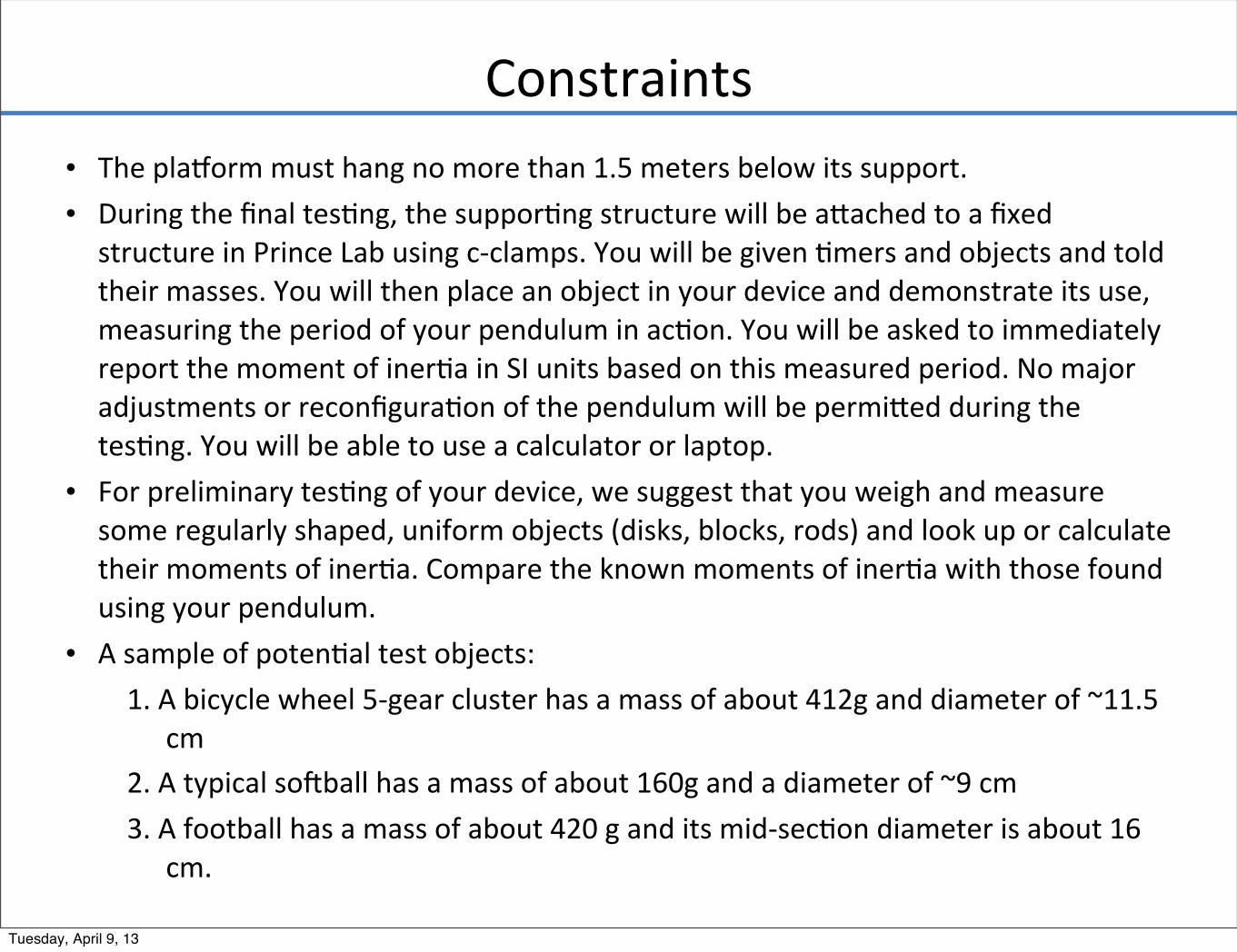
Constraints• The plaForm must hang no more than 1.5 meters below its support. • During the final tes2ng, the suppor2ng structure will be aeached to a fixed
structure in Prince Lab using c-‐clamps. You will be given 2mers and objects and told their masses. You will then place an object in your device and demonstrate its use, measuring the period of your pendulum in ac2on. You will be asked to immediately report the moment of iner2a in SI units based on this measured period. No major adjustments or reconfigura2on of the pendulum will be permieed during the tes2ng. You will be able to use a calculator or laptop.
• For preliminary tes2ng of your device, we suggest that you weigh and measure some regularly shaped, uniform objects (disks, blocks, rods) and look up or calculate their moments of iner2a. Compare the known moments of iner2a with those found using your pendulum.
• A sample of poten2al test objects: 1. A bicycle wheel 5-‐gear cluster has a mass of about 412g and diameter of ~11.5
cm 2. A typical solball has a mass of about 160g and a diameter of ~9 cm 3. A football has a mass of about 420 g and its mid-‐sec2on diameter is about 16
cm.
Tuesday, April 9, 13
Materials and Construc;on
• The pendulum may be constructed from the following materials: – Foam-‐core board – Perforated Aluminum Sheet – Plywood (12”x12” squares of 1/2”, ¼” thickness should be available) – 2x4
• The top support structure can be made of wood – plywood is probably preferable.
• Various types of string and cable, hooks, bolts, screws, brackets, and other miscellaneous hardware will be available in Prince Lab.
• Construc;on will take place in Prince Lab. Hand tools, X-‐Acto knives, and small power tools will be available for cubng and drilling.
• Power tools may only be used under the supervision of Mr. Brian Corkum or one of the Lab TAs.
• Mr. Corkum will supervise the overall use of the lab, and is an invaluable source of insight and advice.
• Construc;on can be performed during day;me hours April 16-‐20. TAs and faculty will be available during normal sec;on ;mes, in the adernoon hours
Tuesday, April 9, 13
Safety
• Wear safety glasses when working on the project.
• Tie back all hair and loose clothing. • Clamp all work pieces while being cut or drilled • NO OPEN TOED SHOES IN PRINCE LAB • BE CAREFUL!
Tuesday, April 9, 13
• Classroom sec;ons will not be held: faculty will be in Prince Lab!
• Evening TA office hrs will not be held next week, instead TAs are available during day for construc;on help!
• No regular faculty office hours, faculty will be helping in prince lab instead.
Tuesday, April 9, 13