Instrumentation and Modelling of Injection Stretch Blow...
22
Instrumentation and Modelling of Injection Stretch Blow Moulding Dr. Gary H Menary, Mr. Yannis Salomeia and Prof. Cecil G Armstrong School of Mechanical and Aerospace Engineering Queen’s University of Belfast, N Ireland
Transcript of Instrumentation and Modelling of Injection Stretch Blow...

Instrumentation and Modelling of Injection Stretch Blow Moulding
Dr. Gary H Menary, Mr. Yannis Salomeia and Prof. Cecil G Armstrong
School of Mechanical and Aerospace Engineering
Queen’s University of Belfast, N Ireland
�Aim of research
�Data acquisition principle & equipment
� Pre-form temperature measurements
� Results from industrial trials
� Modelling of ISBM
� Conclusions
OUTLINE
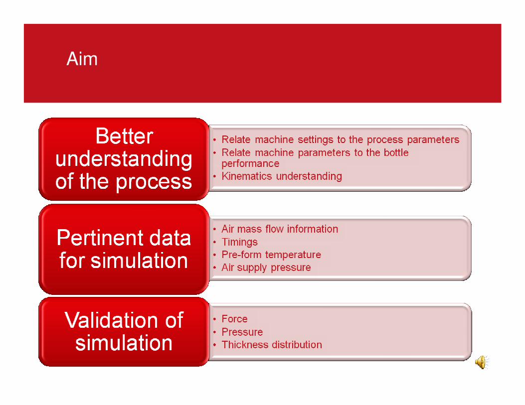
Aim
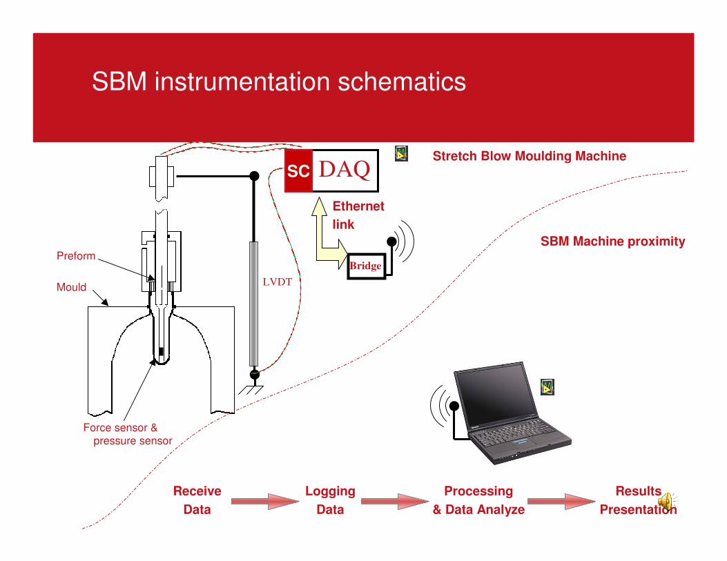
SBM instrumentation schematics
Preform
MouldLVDT
Stretch Blow Moulding Machine
Force sensor & pressure sensor
Bridge
Ethernet
link
DAQ
Receive
Data
Logging
Data
Processing
& Data Analyze
Results
Presentation
SBM Machine proximity
SC
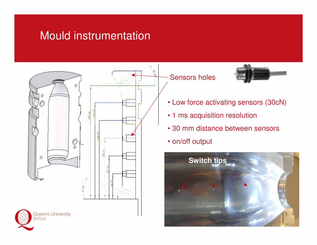
Mould instrumentation
Switch tips
Sensors holes
• Low force activating sensors (30cN)
• 1 ms acquisition resolution
• 30 mm distance between sensors
• on/off output
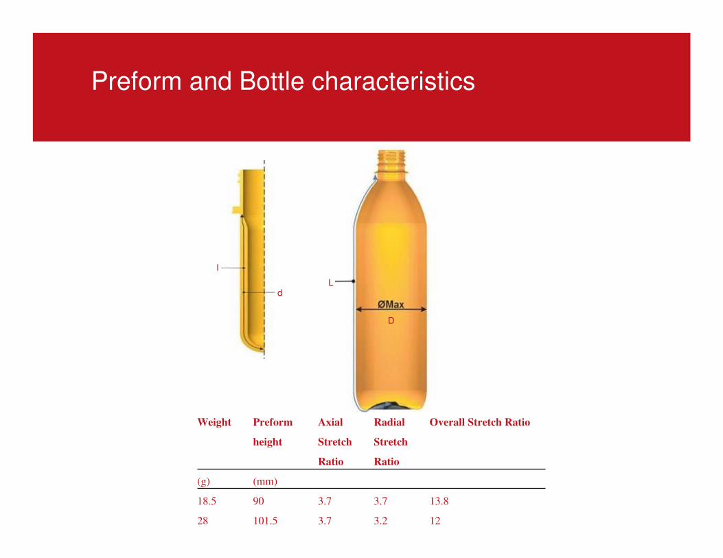
Preform and Bottle characteristics
Weight Preform
height
Axial
Stretch
Ratio
Radial
Stretch
Ratio
Overall Stretch Ratio
(g) (mm)
18.5 90 3.7 3.7 13.8
28 101.5 3.7 3.2 12
D
L
l
d
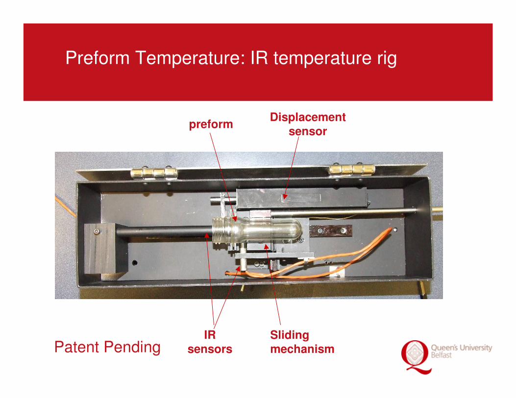
Preform Temperature: IR temperature rig
Displacement
sensor
Sliding mechanism
IR sensors
preform
Patent Pending
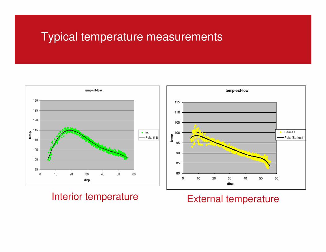
Typical temperature measurements
temp-int-low
95
100
105
110
115
120
125
130
0 10 20 30 40 50 60
disp
tem
p int
Poly. (int)
80
85
90
95
100
105
110
115
0 10 20 30 40 50 60
tem
p
disp
temp-ext-low
Series1
Poly. (Series1)
Interior temperature External temperature
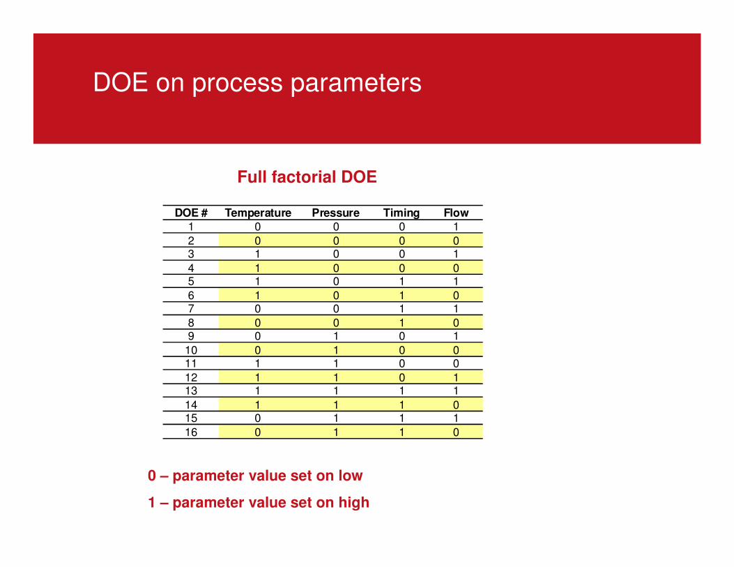
DOE on process parameters
Full factorial DOE
0 – parameter value set on low
1 – parameter value set on high
DOE # Temperature Pressure Timing Flow
1 0 0 0 1
2 0 0 0 03 1 0 0 1
4 1 0 0 05 1 0 1 1
6 1 0 1 07 0 0 1 1
8 0 0 1 09 0 1 0 1
10 0 1 0 011 1 1 0 0
12 1 1 0 113 1 1 1 1
14 1 1 1 015 0 1 1 1
16 0 1 1 0
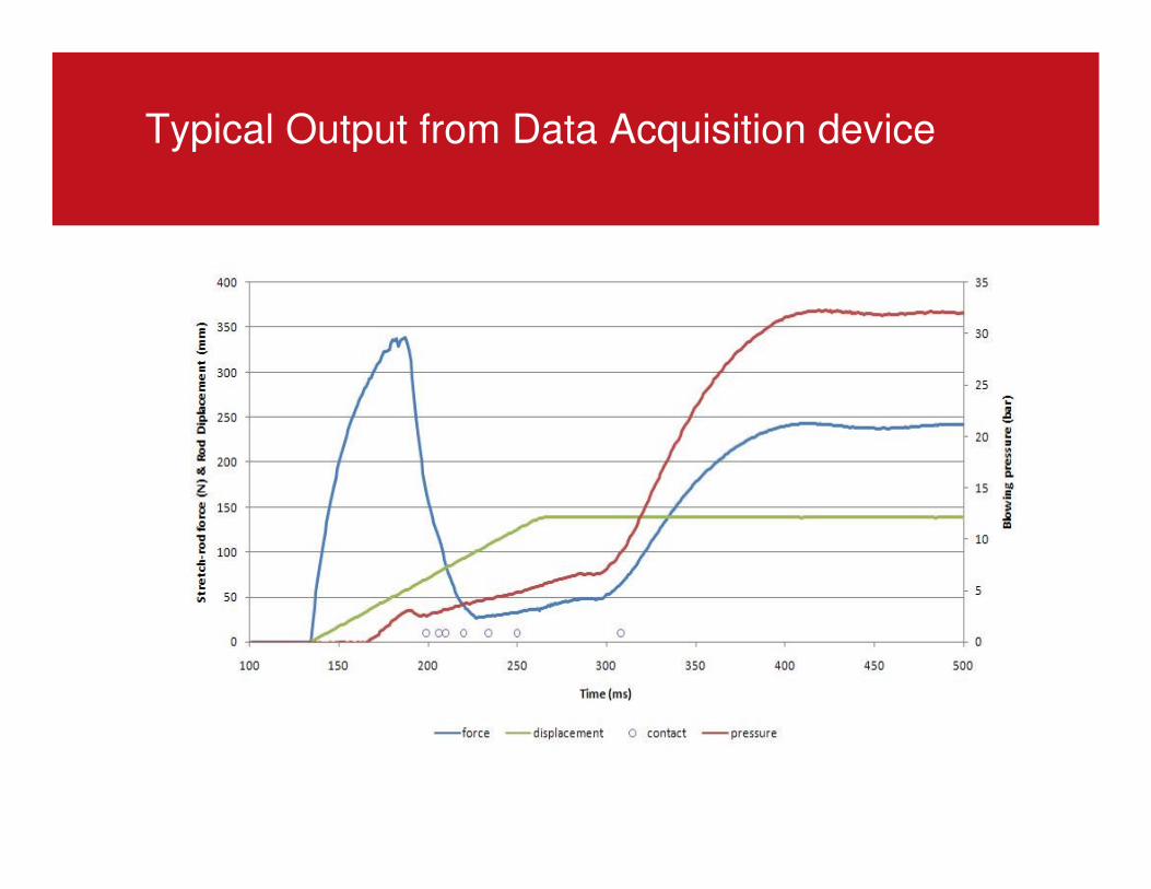
Typical Output from Data Acquisition device
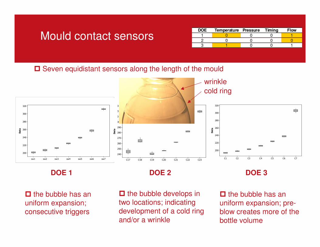
Mould contact sensors
Data
sw7sw6sw5sw4sw3sw2sw1
320
300
280
260
240
220
200
Boxplot of sw1, sw2, sw3, sw4, sw5, sw6, sw7
Data
C23C22C21C20C19C18C17
330
320
310
300
290
280
270
260
250
240
Boxplot of C17, C18, C19, C20, C21, C22, C23
Data
C7C6C5C4C3C2C1
320
300
280
260
240
220
200
Boxplot of C1, C2, C3, C4, C5, C6, C7
DOE 1 DOE 2 DOE 3
� the bubble has an
uniform expansion;
consecutive triggers
� the bubble develops in
two locations; indicating
development of a cold ring
and/or a wrinkle
� the bubble has an
uniform expansion; pre-
blow creates more of the
bottle volume
� Seven equidistant sensors along the length of the mould
cold ring
wrinkle
DOE Temperature Pressure Timing Flow
1 0 0 0 1
2 0 0 0 03 1 0 0 1
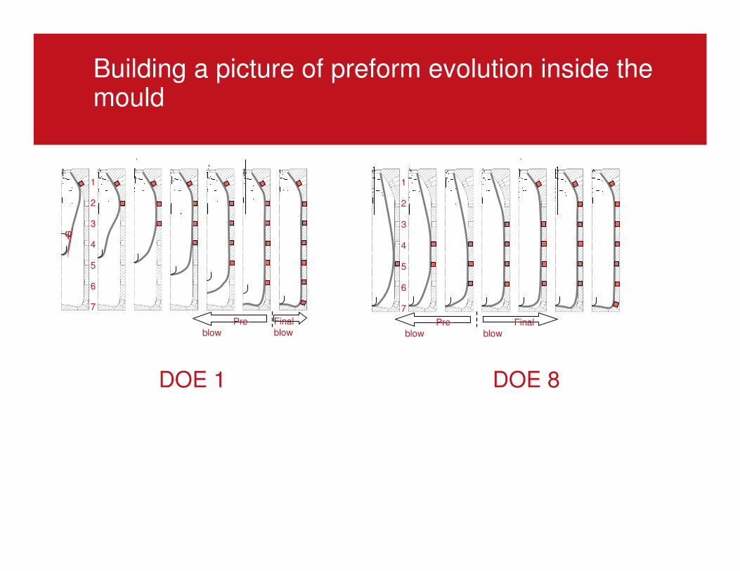
Building a picture of preform evolution inside the mould
1
2
3
4
5
6
7
Final
blowPre-
blow
φ
1
2
3
4
5
6
7
Final
blow
Pre-
blow
DOE 1 DOE 8
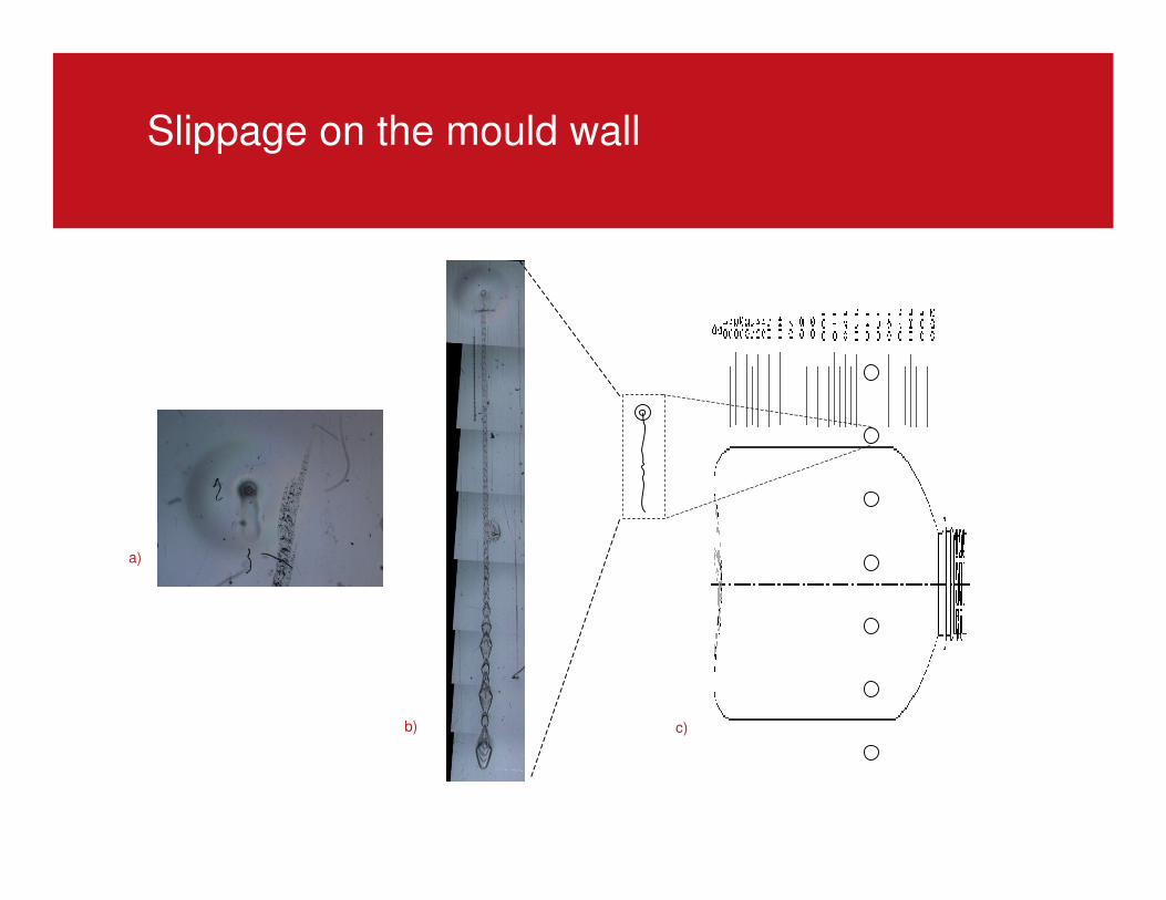
Slippage on the mould wall
a)
b) c)
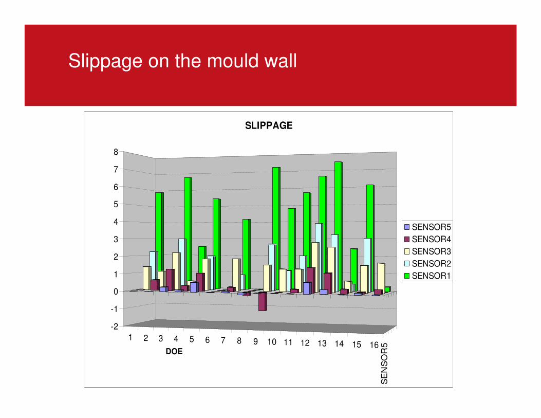
Slippage on the mould wall
1 2 3 4 5 6 7 8 9 10 11 12 13 14 15 16
SE
NS
OR
5
-2
-1
0
1
2
3
4
5
6
7
8
DOE
SLIPPAGE
SENSOR5
SENSOR4
SENSOR3
SENSOR2
SENSOR1
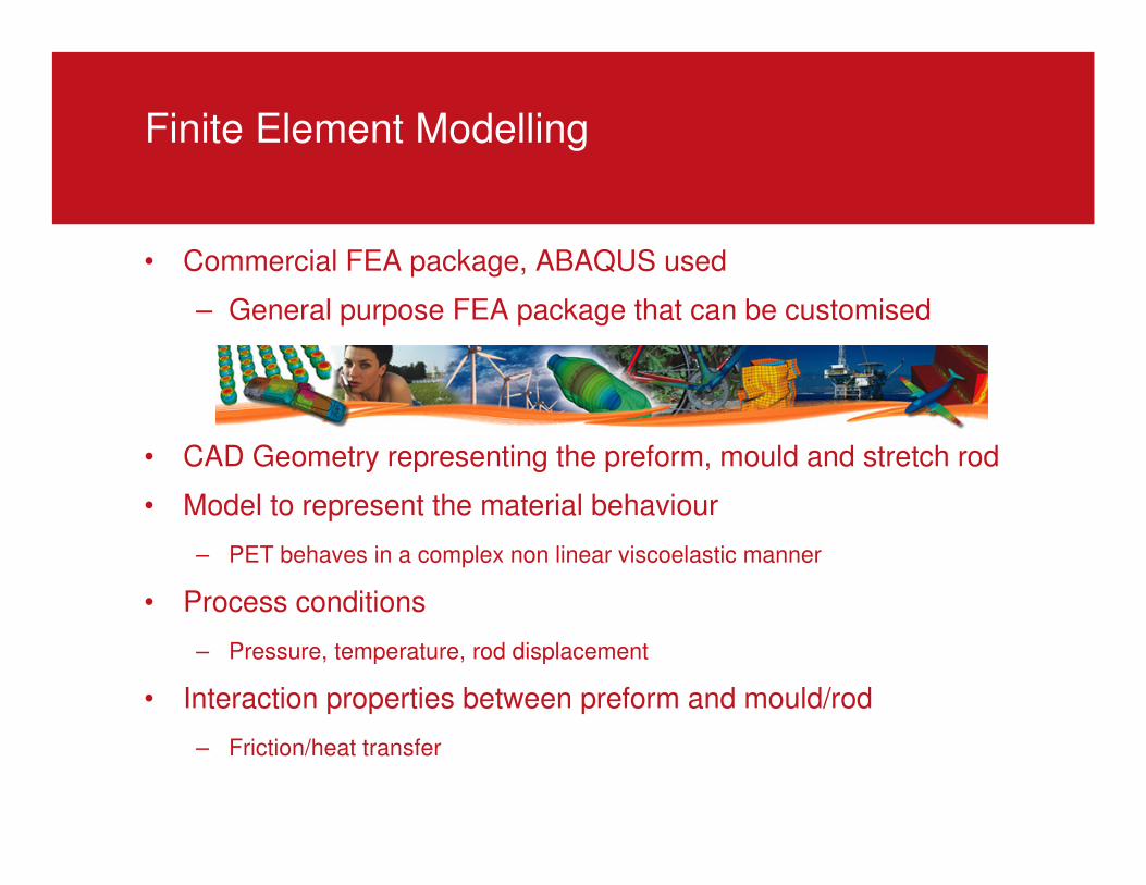
Finite Element Modelling
• Commercial FEA package, ABAQUS used
– General purpose FEA package that can be customised
• CAD Geometry representing the preform, mould and stretch rod
• Model to represent the material behaviour
– PET behaves in a complex non linear viscoelastic manner
• Process conditions
– Pressure, temperature, rod displacement
• Interaction properties between preform and mould/rod
– Friction/heat transfer
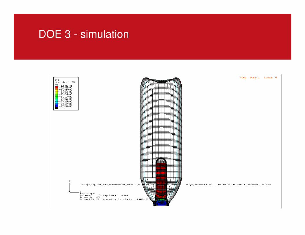
DOE 3 - simulation
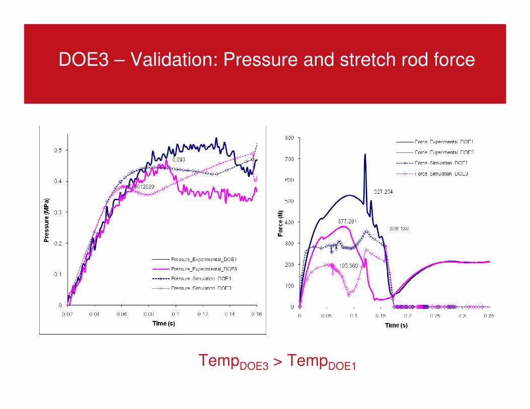
DOE3 – Validation: Pressure and stretch rod force
TempDOE3 > TempDOE1
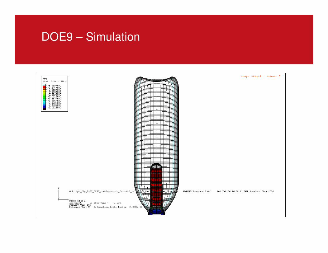
DOE9 – Simulation
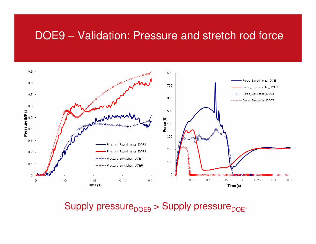
DOE9 – Validation: Pressure and stretch rod force
Supply pressureDOE9 > Supply pressureDOE1
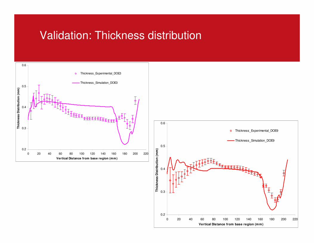
Validation: Thickness distribution
0.2
0.3
0.4
0.5
0.6
0 20 40 60 80 100 120 140 160 180 200 220
Vertical Distance from base region (mm)
Th
ickn
ess D
istr
ibu
tio
n (
mm
)
Thickness_Experimental_DOE9
Thickness_Simulation_DOE9
0.2
0.3
0.4
0.5
0.6
0 20 40 60 80 100 120 140 160 180 200 220
Vertical Distance from base region (mm)
Th
ickn
ess D
istr
ibu
tio
n (
mm
)
Thickness_Experimental_DOE3
Thickness_Simulation_DOE3
Conclusions
� Capable of deploying a wireless data acquisition system on an industrial
ISBM machine
□ Measurements of pressure, stretch rod force and displacement.
□ Bubble kinematics
□ Air Temperature
□ Internal and External preform temperature distribution
□ Numerical simulation of ISBM process has been developed using
commercial FEA packages ABAQUS
□ Validation of pressure and stretch rod force
□ Thickness predictions still not ideal
□ Material model – strain hardening too soon?
□ Further understanding of contact conditions is required to improve
the simulation
Acknowledgements
• Logoplaste
– For performing ISBM trials
• Apt_Pack project partners


![[Gokigenyou] Stretch v.1 EXTRA](https://static.fdocument.pub/doc/165x107/577cb1441a28aba7118b9812/gokigenyou-stretch-v1-extra.jpg)