Information Science 1 - 立命館大学piumarta/is1/slides/IS1-06.pdf · Flowchart ! A flowchart is...
31
Information Science 1 Program Development Algorithms and Problem Solving College of Information Science and Engineering Ritsumeikan University Week 06
Transcript of Information Science 1 - 立命館大学piumarta/is1/slides/IS1-06.pdf · Flowchart ! A flowchart is...
Information Science 1
Program Development
-‐Algorithms and Problem Solving-‐
College of Information Science and Engineering Ritsumeikan University
Week 06
2
Topics covered l Terms and concepts from Week 05 l The software development process
– software – software life cycle – life-cycle models
l Software design - algorithm - design (and development) formal tools
l Quiz

3
Recall Week 05 l Signed, unsigned l Positive, negative l Real numbers, floating point numbers l Signed magnitude, sign-magnitude l Two’s complement (2’s complement) l Invert, flip, 1’s complement l Duplicate, sign extension l Range, out of range, overflow l IEEE 754 (“I triple E 754”) l Exponent, fraction, infinity, NaN

4
Our goals today l To understand the software
development process
l To introduce the concept of the software product life cycle and software process models
l To learn what an algorithm is
l To survey popular formal tools used in program design and development
5
The concept of software product
l A specific set of computer programs and associated documentation (such as user requirements, design models, user manuals, etc) are called a software product
l A software product may be developed for a particular customer – custom software – or for a general market – generic software
l A new software product can be created by developing new programs, configuring generic software systems, or reusing existing software

6
The software development process
l The software development process is a set of activities having their goal as the development or evolution of software. It always includes: - Specification: What the system should do and
its development constraints - Development: Production of the software
system - Validation: Checking that the developed
software is what the customer wants - Evolution: Changing the software in response
to changing demands
7
Software life cycle l All the processes of software development
and use are called the software processes. The software life cycle is an ordered set of software processes
l Fundamental assumptions of software product development: - Good software processes lead to good
products - Good software processes reduce risk
l Software process models are simplified representations of the software life cycle, presented from a specific perspective
8
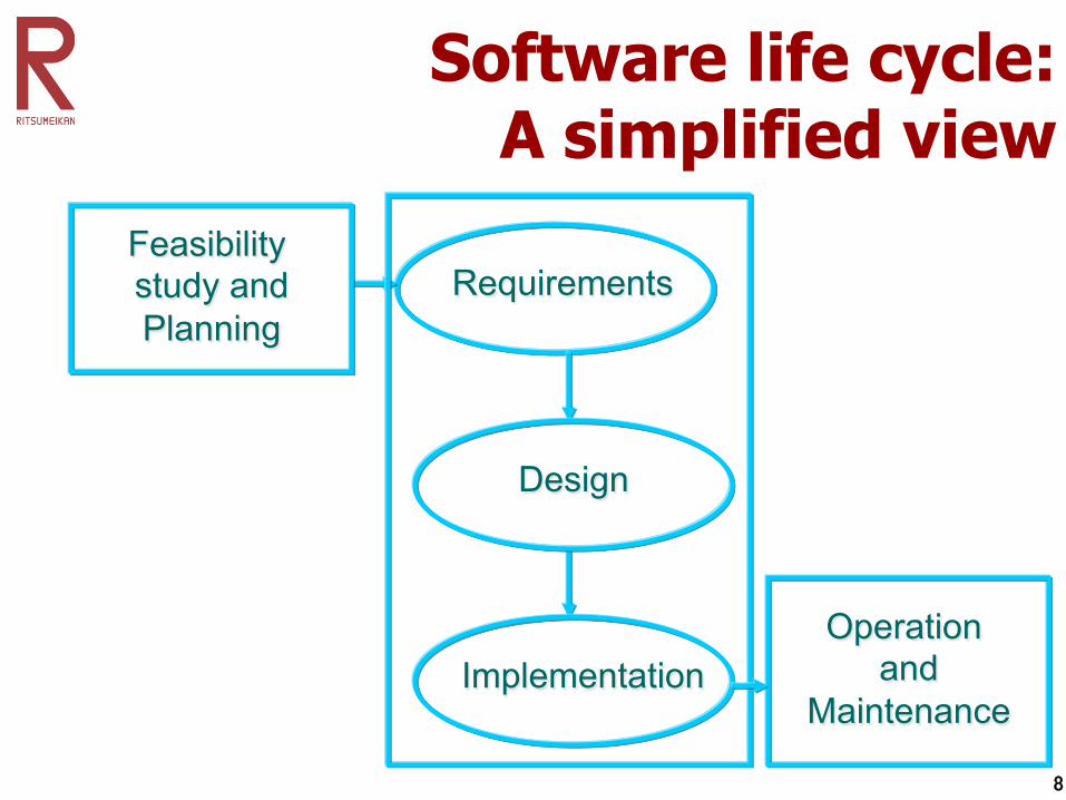
Software life cycle: A simplified view
Requirements
Operation and
Maintenance Implementation
Design
Feasibility study and Planning

9
The Waterfall model
Requirements Analysis
System design
Unit Testing & Integration
System Testing
Operation & Maintenance
Program design
Coding
Acceptance Testing Software processes
Assumed order

10
Requirements analysis l This phase of the software life cycle is to
establish system's services, constraints, and goals through interaction with system prospective users (i.e. the client)
l The requirements analysis phase is usually comprised of activities related to:
- Feasibility study (which is often carried out separately from other activities)
- Requirements elicitation (i.e. understanding and analysis of what the client needs)
- Requirements definition - Requirements specification

11
System and Program design l The system design phase is to establish an
overall system architecture, and to partition all the requirements into hardware requirements and software requirements
l During the program design phase, the previously established system functions are represented in a form that can unambiguously be understood and can be transformed into one or more executable programs
12
Coding and Unit testing l Through coding (or, in other words,
programming), the software design is realized as a set of programs or program units. These programs can be written specifically, acquired from elsewhere, or obtained by modifying programs developed previously
l Individual programs and subsystems are tested against specifications during the unit testing phase

13
Integration, System testing, and Acceptance testing
l Integration and system testing are usually concurrent activities that include: - Integration of individual programs into larger
modules (subsystems) and, ultimately, into a complete system
- Testing the subsystems and, then, the whole system against the specified requirements
- Delivering the system to the client l During acceptance testing, the client
performs independent testing before accepting the system and putting it into operation

14
Operation and Maintenance l This phase of the software life cycle
includes activities related to — System operation: The product is put
into practical use — System maintenance: Errors/“bugs” and
other problems are identified and fixed — System evolution: The product evolves
over time as requirements change, to add new functions or adapt to the technical environment
— Phasing out of the software product: The system is withdrawn from service

15
Feedback and the Waterfall model Requirements Analysis
System design
Unit & Integration Testing
System Testing
Operation & Maintenance
Program design
Coding
Acceptance Testing
Each phase may need to be iteratively refined due to new understanding emerging at later stages

16
System documentation l Each (sub)system’s documentation
describes the purpose of the processing system, and it usually includes: — Computer system flowcharts — Input and output descriptions — File descriptions — Error messages
l System documentation also assigns responsibility for performing each control and processing procedure, as well as error-correction procedures

17
The concept of algorithm l Definition:
An algorithm is a finite set of unambiguous, executable instructions that direct a terminating activity
l In an algorithm, always — the number of steps (instructions) is
finite — we are able to do each of the
instructions — when we have followed all of the steps,
we obtain a solution, and then stop

18
Designing Algorithms: A Methodology
1. Read the problem and establish the input and the output
2. Identify, what variables are needed? 3. Figure out, what computations are required to
achieve the output? l Usually, first steps in your algorithm are to
bring input values to the variables l Usually, last steps are to display the output l So, the middle steps are to do the
computation l If processes are to be repeated, add loops

19
Algorithm design tools: Flowchart
l A flowchart is a logic diagram used to describe each step that the program must perform to arrive at the solution
l It is a very popular design tool used for showing an algorithm in a graphical form. Most common flowchart symbols are:
Direction of logic flow
Beginning or end of a task
Input/output operation
Logic comparison operation. Always has one entry and two exit points
Data manipulation operations e.g arithmetic
Logic flow connectors

20
Flowchart: Example l Suppose you want to calculate the
squares of the integers from 2 to 7 – a simple solution would be to arrange a loop
for both calculation and display
is i > 7 ? i = 2
i = i + 1
NO
YES
Display i 2 Start
Stop

21
5 purposes of flowcharting 1. An aid in developing the logic of a
program 2. Verification that all possible conditions
have been considered in a program 3. Provides a means of communicating
with others about algorithms (especially good for international communication)
4. A guide in coding the program 5. Documentation for the program

22
Algorithm design tools: Pseudocode
l Pseudocode is a textual description of a program l Basic pseudocode operations:
— Read the input from user — Print/Display the output to the user — Carry out basic arithmetical computations — Conditional operations: Execute an operation if
the condition is true — Repeat operations: Execute a block operation
multiple times until a certain condition is met l Pseudocode is a simplified form of English (or any
other natural language – Japanese, Vietnamese, Arabic, etc), but looks like programming
23
Algorithm design tools: Hierarchy chart
l Hierarchy chart is a graphical description of how parts of a (sub)system are connected
l A hierarchy chart: — Shows the overall system structure — Describes what each part, or module, of the
system does — Also shows how each module relates to other
modules in the system l There are two hierarchy chart symbols: rectangles
(to indicate the parts) and lines (to connect related modules). Arrows may also be used to show the flow
24
Algorithm design tools: UML l The Unified Modeling Language (UML) is a
language for – visualizing, – specifying, – constructing, and – documenting an information system
l UML is not “just for” software development, and it can be used “outside” the domain of computer (information) science
25
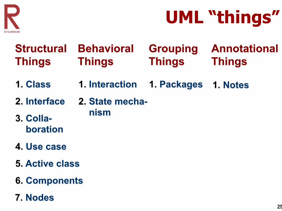
UML “things”
Structural Things 1. Class
2. Interface
3. Colla- boration
4. Use case
5. Active class
6. Components
7. Nodes
Behavioral Things
2. State mecha- nism
1. Interaction
Grouping Things 1. Packages
Annotational Things 1. Notes
26
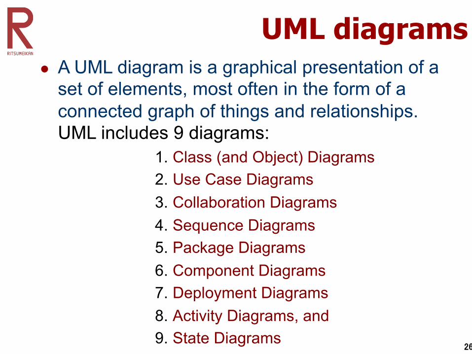
UML diagrams l A UML diagram is a graphical presentation of a
set of elements, most often in the form of a connected graph of things and relationships. UML includes 9 diagrams:
1. Class (and Object) Diagrams 2. Use Case Diagrams 3. Collaboration Diagrams 4. Sequence Diagrams 5. Package Diagrams 6. Component Diagrams 7. Deployment Diagrams 8. Activity Diagrams, and 9. State Diagrams

27
UML: Example (a class diagram)
DVD Movie VHS Movie Video Game
Rental Item {abstract}
Rental Invoice
1..* 1
Customer
Checkout Screen
0..1
1
Simple Association
Class
Abstract Class
Simple Aggregation
Generalization
Composition (Dependency)
Multiplicity

28
What you are supposed to know after this class
l The phases of the software life cycle (as in the Waterfall model)
l Algorithm definition l Software design tools: flowchart
and pseudocode l You are also advised to learn
hierarchy charts and, especially, (in the future) the UML
29
Homework
l Read these slides l Do the self-preparation work l Learn the vocabulary l Consult, whenever necessary, the
textbook materials
30
Next class
l Overview and mid-semester evaluation for the first six weeks: from Week 01 to Week 06

31
Quiz 03