Image magnified lensless holographic projection by...
6
Image magnified lensless holographic projection by convergent spherical beam illumination Chenliang Chang (常琛亮) 1,2, *, Yijun Qi (祁怡君) 2 , Jun Wu (吴 俊) 2 , Jun Xia (夏 军) 2 , and Shouping Nie (聂守平) 1 1 Jiangsu Key Laboratory for Opto-Electronic Technology, School of Physics and Technology, Nanjing Normal University, Nanjing 210023, China 2 Joint International Research Laboratory of Information Display and Visualization, School of Electronic Science and Engineering, Southeast University, Nanjing 210096, China *Corresponding author: [email protected] Received July 11, 2018; accepted August 27, 2018; posted online September 21, 2018 In liquid crystal spatial light modulator (SLM)-based holographic projection, the image is usually displayed at a distant projection screen through free space diffraction from a computer-generated hologram (CGH). Therefore, it allows for removing of the projection lens for the sake of system simplification and being aberration free, known as the “lensless holographic projection”. However, the maximum size of the optical projected image is limited by the diffraction angle of the SLM. In this Letter, we present a method for the implementation of image magni- fication in a lensless holographic projection system by using convergent spherical wave illumination to the SLM. The complete complex amplitude of the image wavefront is reconstructed in a lensless optical filtering system from a phase-only CGH that is encoded by the off-axis double-phase method. The dimensions of the magnified image can break the limitation by the maximum diffraction angle of the SLM at a given projection distance. Optical experiment results with successful image magnification in the lensless holographic projection system are presented. OCIS codes: 090.2870, 090.1760. doi: 10.3788/COL201816.100901. Attention to holographic projection has increased in the past decade. In a traditional holographic projector, the size of the projected images can be easily magnified through the imaging system, which involves zoom lenses. For example, the optical projected image could be magni- fied by using either the 4f system [ 1] or one lens with a di- vergent spherical illumination [ 2, 3] . However, the existing projection lenses would increase the complexity of the pro- jection system and introduce lens aberration. Since in holographic projection the projected image is reconstructed via diffraction from the computer-generated hologram (CGH), the reconstructed distance and size of the image can be controlled digitally in the numerical calculation of Fresnel diffraction from the image to the CGH. Therefore, it allows abandoning bulks of imaging and zoom lenses, also referred as lensless holographic pro- jection [ 4, 5] , and shows great potential in a variety of appli- cations towards portable and miniature projection systems. Generally, while the holographic projection is optically achieved by loading the CGH into a dynamic spatial light modulator (SLM), the concept of “lensless” in a holographic projection system could be classified into two categories according to the previously reported works. (1) There are absolutely no lenses in the whole optical setup [ 4– 6] , as shown in Fig. 1(a). In this type, the direct point light source with high divergence, such as an optical fiber, is usually used as the illumination source, allow- ing the realization of miniaturized holographic pico- projectors. (2) There are no lenses existing between the SLM and the projection screen, but a lens (or lenses) responsible for beam collimation could be permitted before illumination to the SLM [ 7– 9] , such as in the case shown in Fig. 1(b). Although the beam collimation lens is used, it can still be called a “lensless” holographic projection since the expression of “lensless” mainly refers to the substan- tive holographic projection process that happens between the SLM (CGH) and the screen via Fresnel diffraction. In this Letter, our work of lensless holographic projection is mainly focused on the second case. In lensless holographic projection, the CGH that needs to be loaded into the SLM is calculated from the projected image at a given distance by using the Fresnel diffraction algorithms. The fast Fourier transforms (FFTs) used in the Fresnel diffraction calculation map the CGH in the SLM plane onto a target image in the image plane, and then, the image size is restricted by the diffraction angle of the used SLM. Due to the fact that the maximum diffraction angle depends on the pixel pitch of the SLM, the maximum reachable dimension of the projected image is determined by the so-called Nyquist criterion of Fig. 1. Two cases for lensless holographic projection. COL 16(10), 100901(2018) CHINESE OPTICS LETTERS October 10, 2018 1671-7694/2018/100901(6) 100901-1 © 2018 Chinese Optics Letters
Transcript of Image magnified lensless holographic projection by...

Image magnified lensless holographic projection byconvergent spherical beam illumination
Chenliang Chang (常琛亮)1,2,*, Yijun Qi (祁怡君)2, Jun Wu (吴 俊)2, Jun Xia (夏 军)2,and Shouping Nie (聂守平)1
1Jiangsu Key Laboratory for Opto-Electronic Technology, School of Physics and Technology, Nanjing NormalUniversity, Nanjing 210023, China
2Joint International Research Laboratory of Information Display and Visualization, School of Electronic Science andEngineering, Southeast University, Nanjing 210096, China
*Corresponding author: [email protected] July 11, 2018; accepted August 27, 2018; posted online September 21, 2018
In liquid crystal spatial light modulator (SLM)-based holographic projection, the image is usually displayed at adistant projection screen through free space diffraction from a computer-generated hologram (CGH). Therefore,it allows for removing of the projection lens for the sake of system simplification and being aberration free, knownas the “lensless holographic projection”. However, the maximum size of the optical projected image is limited bythe diffraction angle of the SLM. In this Letter, we present a method for the implementation of image magni-fication in a lensless holographic projection system by using convergent spherical wave illumination to the SLM.The complete complex amplitude of the image wavefront is reconstructed in a lensless optical filtering systemfrom a phase-only CGH that is encoded by the off-axis double-phase method. The dimensions of the magnifiedimage can break the limitation by the maximum diffraction angle of the SLM at a given projection distance.Optical experiment results with successful image magnification in the lensless holographic projection system arepresented.
OCIS codes: 090.2870, 090.1760.doi: 10.3788/COL201816.100901.
Attention to holographic projection has increased in thepast decade. In a traditional holographic projector, thesize of the projected images can be easily magnifiedthrough the imaging system, which involves zoom lenses.For example, the optical projected image could be magni-fied by using either the 4f system[1] or one lens with a di-vergent spherical illumination[2,3]. However, the existingprojection lenses would increase the complexity of the pro-jection system and introduce lens aberration.Since in holographic projection the projected image is
reconstructed via diffraction from the computer-generatedhologram (CGH), the reconstructed distance and sizeof the image can be controlled digitally in the numericalcalculation of Fresnel diffraction from the image to theCGH. Therefore, it allows abandoning bulks of imagingand zoom lenses, also referred as lensless holographic pro-jection[4,5], and shows great potential in a variety of appli-cations towards portable and miniature projection systems.Generally, while the holographic projection is optically
achieved by loading the CGH into a dynamic spatiallight modulator (SLM), the concept of “lensless” in aholographic projection system could be classified intotwo categories according to the previously reported works.(1) There are absolutely no lenses in the whole opticalsetup[4–6], as shown in Fig. 1(a). In this type, the directpoint light source with high divergence, such as an opticalfiber, is usually used as the illumination source, allow-ing the realization of miniaturized holographic pico-projectors. (2) There are no lenses existing between the
SLM and the projection screen, but a lens (or lenses)responsible for beam collimation could be permitted beforeillumination to the SLM[7–9], such as in the case shown inFig. 1(b). Although the beam collimation lens is used, itcan still be called a “lensless” holographic projection sincethe expression of “lensless” mainly refers to the substan-tive holographic projection process that happens betweenthe SLM (CGH) and the screen via Fresnel diffraction. Inthis Letter, our work of lensless holographic projection ismainly focused on the second case.
In lensless holographic projection, the CGH that needsto be loaded into the SLM is calculated from the projectedimage at a given distance by using the Fresnel diffractionalgorithms. The fast Fourier transforms (FFTs) used inthe Fresnel diffraction calculation map the CGH in theSLM plane onto a target image in the image plane, andthen, the image size is restricted by the diffraction angleof the used SLM. Due to the fact that the maximumdiffraction angle depends on the pixel pitch of the SLM,the maximum reachable dimension of the projected imageis determined by the so-called Nyquist criterion of
Fig. 1. Two cases for lensless holographic projection.
COL 16(10), 100901(2018) CHINESE OPTICS LETTERS October 10, 2018
1671-7694/2018/100901(6) 100901-1 © 2018 Chinese Optics Letters
L ¼ λz∕dx, where λ is the light wavelength, z is theprojection distance, and dx is the pixel pitch of theSLM. Shimobaba et al. proposed a method of lenslesszoomable holographic projection, where the image sizecan be adjustable during the calculation of CGH by em-ploying a convolution-based aliasing-reduced shifted andscaled (ARSS)-Fresnel diffraction algorithm[6,10]. Thus, theimage can be magnified by presetting the image pixel pitchthrough diffraction calculation. An alternative method foradjusting image dimension in CGH calculation is also re-ported in Ref. [11] by using the double-step Fresnel diffrac-tion algorithm. However, the maximum size of the imagein both of these methods is still limited by the Nyquist cri-terion due to the restrictive diffraction angle of the SLM.Using a spherical wave to illuminate the SLM is an effec-
tive solution to break the Nyquist criterion and enlarge thesize of the reconstructed image. By introducing a sphericalillumination wavefront, the diffraction angle of the SLM isincreased, and the diffraction region occupied by the pro-jected image is further enlarged. Qu et al. proposed amethod for image magnification in lensless holographic pro-jection[9]. The SLM is illuminated by a divergent sphericalbeam, and the size of the optical projected image can exceedthe traditional Nyquist limit. But, the phase-only CGHused in the experiment is generated by the Gerschberg–Saxton (GS) algorithm[12], and the image would be de-graded by the presence of speckle noise.In this Letter, we propose an image magnified lensless
holographic projection system. Instead of using a diver-gent beam, we use a convergent spherical wave illumina-tion to increase the diffraction angle of the SLM, thereforeenabling the dimension magnification of the projectionimage, as well as maintaining the high image quality ofspeckle noise suppression due to the reconstruction ofcomplex amplitude of the image via a lensless opticalfiltering system. In this way, a large-sized and high-definition lensless holographic projection is achieved.We first briefly review the principle of CGH calculation
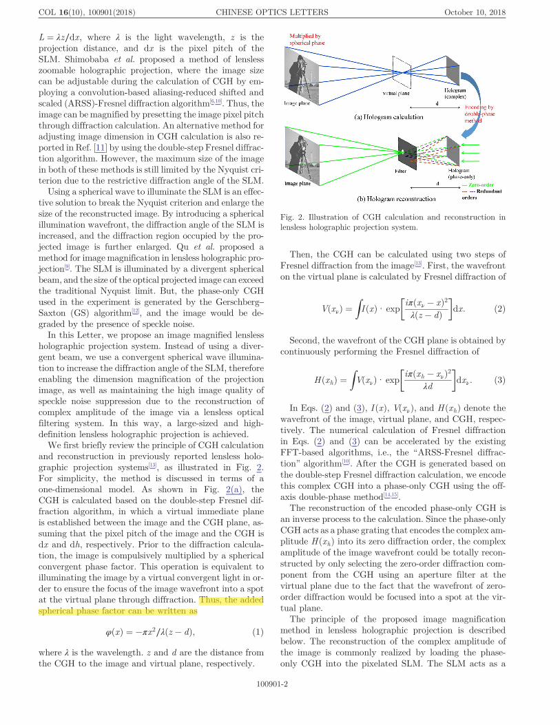
and reconstruction in previously reported lensless holo-graphic projection systems[13], as illustrated in Fig. 2.For simplicity, the method is discussed in terms of aone-dimensional model. As shown in Fig. 2(a), theCGH is calculated based on the double-step Fresnel dif-fraction algorithm, in which a virtual immediate planeis established between the image and the CGH plane, as-suming that the pixel pitch of the image and the CGH isdx and dh, respectively. Prior to the diffraction calcula-tion, the image is compulsively multiplied by a sphericalconvergent phase factor. This operation is equivalent toilluminating the image by a virtual convergent light in or-der to ensure the focus of the image wavefront into a spotat the virtual plane through diffraction. Thus, the addedspherical phase factor can be written as
φðxÞ ¼ −πx2∕λðz − dÞ; (1)
where λ is the wavelength. z and d are the distance fromthe CGH to the image and virtual plane, respectively.
Then, the CGH can be calculated using two steps ofFresnel diffraction from the image[13]. First, the wavefronton the virtual plane is calculated by Fresnel diffraction of
VðxνÞ ¼ZI ðxÞ·exp
�iπðxν − xÞ2λðz − dÞ
�dx: (2)
Second, the wavefront of the CGH plane is obtained bycontinuously performing the Fresnel diffraction of
HðxhÞ ¼ZVðxνÞ·exp
�iπðxh − xνÞ2
λd
�dxν: (3)
In Eqs. (2) and (3), I ðxÞ, VðxνÞ, and H ðxhÞ denote thewavefront of the image, virtual plane, and CGH, respec-tively. The numerical calculation of Fresnel diffractionin Eqs. (2) and (3) can be accelerated by the existingFFT-based algorithms, i.e., the “ARSS-Fresnel diffrac-tion” algorithm[10]. After the CGH is generated based onthe double-step Fresnel diffraction calculation, we encodethis complex CGH into a phase-only CGH using the off-axis double-phase method[14,15].
The reconstruction of the encoded phase-only CGH isan inverse process to the calculation. Since the phase-onlyCGH acts as a phase grating that encodes the complex am-plitude H ðxhÞ into its zero diffraction order, the complexamplitude of the image wavefront could be totally recon-structed by only selecting the zero-order diffraction com-ponent from the CGH using an aperture filter at thevirtual plane due to the fact that the wavefront of zero-order diffraction would be focused into a spot at the vir-tual plane.
The principle of the proposed image magnificationmethod in lensless holographic projection is describedbelow. The reconstruction of the complex amplitude ofthe image is commonly realized by loading the phase-only CGH into the pixelated SLM. The SLM acts as a
Fig. 2. Illustration of CGH calculation and reconstruction inlensless holographic projection system.
COL 16(10), 100901(2018) CHINESE OPTICS LETTERS October 10, 2018
100901-2
51756
高亮

diffractive optical element, and the diffraction angle of themodulated light beam obeys the formula of
sin θdiff − sin θin ≈ θdiff − θin ¼ λ
2dh;
θdiff ¼ θin þλ
2dh; (4)
where θin represents the angle of the incident illuminationbeam, and θdiff represents the maximum diffraction angleafter being modulated by the SLM. Conventionally, theincident angle is θin ¼ 0 since the SLM is illuminatedby the collimated plane waves; so, the viewing angle θ ¼2θdiff ¼ λ∕dh is mainly dependent on the pixel pitch dh ofthe SLM, as shown in Fig. 3(a). The maximum reachablesize of the projection image at a given distance (z) will berestricted by the typical commercial SLM, i.e., dh ¼ 8 μmfor the Holoeye Pluto-type phase-only SLM. Generally,the maximum size of the image can be calculated accord-ing to the Nyquist criterion as L ¼ λz∕dh.An obvious solution for the problem of breaking the
limitation of the image size is to introduce an incident an-gle (θin ≠ 0) of the illumination beam while still maintain-ing the principle of complex amplitude modulation forhigh image quality as described above. This means thattwo necessary requirements should be satisfied at the sametime: firstly, the plane wave illumination should be re-placed by spherical wavefront illumination for the sakeof increasing the diffraction angle; secondly, the beamafter being modulated by the SLM should be focused intoa spot at the virtual plane for further facilitated filteringoperation. Based on these two requirements, the incidentbeam of the convergent spherical wavefront is an optimum
adoption as the illumination. As illustrated in Fig. 3(b),by using convergent spherical wave illumination, theangle of the incident beam as well as the diffractionbeam is both increased, thereby expanding the viewing an-gle (diffraction angle) according to the relation asθ ¼ 2θdiff ¼ 2θin þ λ∕dh. The phase of the spherical illumi-nation on the SLM plane is determined by φðxhÞ ¼−πx2h∕λf so as to be focused on the virtual plane. All ofthe incident light, especially in the corner part, fromthe SLM is guaranteed to converge to the spot withoutlight loss under the illumination of the convergent spheri-cal wave. So, the complete information for the compleximage could be completely reconstructed with a larger sizeof λz∕dh þ 2zθin. In this way, the image can be magnifiedthrough breaking the Nyquist limitation of the SLM, ow-ing to the introduction of the convergent spherical illumi-nation under an incident angle of θin. It should be notedthat owing to the producing of an extra spherical phase onthe SLM, a correction should be performed by addingthe CGH with the conjugated phase of the sphericalillumination.
The image magnification in lensless holographicprojection under spherical illumination is demonstratedin optical experiments. Figure 4 shows the sketch ofthe experimental setup. The laser illumination source(532 nm) is delivered by a convergent lens with a shortfocal lens, which shapes the beam into a convergentspherical wavefront to illuminate the phase-only SLM(Holoeye PLUTO, resolution 1920 × 1080 with pixel pitchof 8 μm). After being modulated by the encoded phase-only CGH, the beam then passes a low-pass filterconsisting of a circular iris whose diameter is 3.3 mm.The complex amplitude of the image is reconstructedon a large projection screen with a smooth, flat surfaceto avoid extra diffusive speckles.
In order to compare the effect of image magnification bythe proposed method, we first reconstruct the image byusing plane wave illumination. Figure 5(a) shows the pro-jection screen of a white board that is placed at distancez ¼ 2 m from the SLM. The resolution of the test image“Monalisa” is 1920 × 1080. Figure 5(b) shows the result ofthe reconstructed image with size of 13.44 cm × 7.56 cm,
Fig. 3. Principle of image magnification by using spherical waveillumination. (a) Plane wave illumination, the maximum reach-able image size is limited by Nyquist criterion. (b) Convergentspherical wave illumination, the image is reconstructed with alarger size due to the enlargement of the diffraction angle.
Fig. 4. Optical setup for lensless holographic projection usingconvergent spherical beam illumination.
COL 16(10), 100901(2018) CHINESE OPTICS LETTERS October 10, 2018
100901-3

whose width (13.44 cm) is almost the maximum diffrac-tion bandwidth limited by the diffraction angle ofthe SLM (λz∕dh). In the CGH calculation of Fig. 5(b),the pixel pitch of the image is dx ¼ 13.44 cm∕1920 ¼ 70 μm. Next, we enlarge the pixel pitch of the im-age to dx ¼ 180 μm in CGH calculation, thereby magni-fying the size of the target image to 34.56 cm × 19.44 cm.The corresponding reconstruction from the SLM underplane wave illumination is shown in Fig. 5(c). The maxi-mum diffraction angle of the SLM is limited by plane waveillumination, resulting in image content loss on the projec-tion screen. The maximum size of the visible image con-tent is restricted by the Nyquist criterion and the restimage contents are blocked by the filter. This problemis overcome by replacing the plane wave illumination withconvergent spherical wave illumination using the setupdisplayed in Fig. 4. The lens position is adjusted to makesure that the incident beam focuses toward the SLM withan incident angle of θin ≈ 3°. As expected, the recon-structed image shown in Fig. 5(d) is visible in the wholepredesigned projection region [marked as red line inFig. 5(a)] due to the enlargement of the diffraction angleof the SLM. The image size has been magnified approxi-mately by 2.6 times (180 μm/70 μm) compared with theresult of Fig. 5(b), which is reconstructed under conven-tional plane wave illumination, proving the image magni-fication in the holographic projection based on theproposed method. It is also noted that, although coherentillumination is used, the reconstructed image shows nosignificant speckle noise, owing to the fact that thesmooth phase (spherical phase) distribution of the com-plex amplitude image is obtained, thus avoiding specklegeneration.Figure 6 shows more experimental results of image
magnified holographic projection under spherical wave
illumination. We show three respective reconstructed re-sults of “Baboon” in Fig. 6(b), “Fruits” in Fig. 6(c), and“Parrots” in Fig. 6(d) with the same magnifiedsize (34.56 cm × 19.44 cm) as the “Monalisa” image inFig. 6(a). Moreover, two animations (Visualizations 1and 2) are also presented to exhibit the dynamic holo-graphic projection of 1080P high-definition videos.Figures 6(e) and 6(f) are one frame extracted from eachanimation, respectively. It should be noted that the ring-ing artifacts appearing at the edge of each reconstructedimage are caused by the rectangular band-limit functionof convolution operation in ARSS-Fresnel diffraction cal-culation. The artifacts can be avoided by employing iter-ative schemes[16] or introducing apodization filtering inCGH calculation.
Finally, another experiment is carried out to furtherprove the feasibility of projecting magnified color imagesby the proposed method. We use the similar scheme ofthe time-sequential control method, as reported inRefs. [13,17] to reconstruct color images. Three phase-only CGHs are calculated independently from the red–green–blue (RGB) component of a color image usingthe double-step Fresnel diffraction algorithm before theyare loaded into the SLM. Three laser beams of red(671 nm), green (532 nm), and blue (473 nm) with a con-vergent spherical wavefront are used to illuminate theSLM in turn to match the current loaded CGH of the cor-responding wavelength. Figures 7(a)–7(c) show thereconstruction of the projected image (“Monalisa”) foreach used wavelength, and Fig. 7(d) is the mixed colorreconstruction. Figures 7(e) and 7(f) are the color recon-structions of the other two images (“Fruits” and “Par-rots”). All of the reconstructions in Fig. 7 are captured
Fig. 5. (a) Projected screen marked with the size of the targetprojected image. (b) Reconstructed image under conventionalplane wave illumination. (c) Reconstructed image with magni-fied size under conventional plane wave illumination. (d) Recon-structed image with magnified size under spherical waveillumination.
Fig. 6. Optical reconstructions of image magnified lensless holo-graphic projection. (a)–(d) Monochromatic reconstructions of“Monalisa”, “Baboon”, “Fruits”, and “Parrots” with imagewidth of 34.56 cm and image height of 19.44 cm, respectively.(e) and (f) are one frame extracted from two 1080P high defini-tion animations (Visualizations 1 and 2), respectively.
COL 16(10), 100901(2018) CHINESE OPTICS LETTERS October 10, 2018
100901-4

from the projection screen 2 m from the SLM, and theyhave the same image size of 34.56 cm × 19.44 cm as wellas the same resolution of 1920 × 1080.The significant merit of the proposed method is the sup-
pression of speckle noise through modulating both ofthe amplitude and phase of the image wavefront; whilein the existing methods[9,18], the calculation of CGH usingthe iterative scheme (i.e., GS algorithm) usually leads touncontrolled (random) phase distribution and thereforeproduces speckle noise. We carry out the simulations totheoretically compare the image quality after consideringthe interference among adjacent image pixels and showthe key role of the phase. The first row in Fig. 8 is thereconstruction by the conventional method (GS-basedCGH), and the image phase is randomly distributed,
whereas the second row is the reconstruction by ourmethod with the designed spherical phase distribution.The actual updated intensities are obtained after calculat-ing the interference among overlapped pixels[5] (addingtheir complex amplitude values). It can be seen that withthe random phase distribution, the actual intensity of theimage has great speckle noise due to the destructive inter-ference (discontinues phase jump) between overlappedpixels; but from the result of our method, we can see thatwith the smooth spherical phase, even if the interferencestill exists, the image is clear because there is no abruptphase change between pixels. The quantitative qualityof the images is analyzed by calculating speckle con-trast[15] in the chosen region (enclosed by solid lines)and peak signal noise ratio (PSNR). The value of specklecontrast is C ¼ 0.0173 by the proposed method, while bythe conventional method it is up to C ¼ 0.5278, provingthe speckle reduction effect by the proposed method basedon complex amplitude (both of amplitude and phase)modulation.
In this Letter, an image magnified lensless holographicprojection system is proposed. The CGH is calculatedfrom the target image by using the double-step Fresneldiffraction algorithm. When using a convergent sphericalbeam to illuminate the SLM, the diffraction angle ofthe SLM will be increased physically. The projected im-age is greatly magnified by breaking the dimension limi-tation of the Nyquist sampling criterion. Both large-sizedmonochromatic and color complex amplitude imageswith suppressed speckle noise are obtained via a lenslessoptical filtering path. The proposed method has thepotential to develop a compact and portable dynamichigh-definition holographic projection and displaysystem.
This work was supported by the National NaturalScience Foundation of China (NSFC) (Nos. 61605080and 61775035) and the National 863 Program of China(No. 2015AA016301).
References1. A. Kaczorowski, G. S. Gordon, and T. D. Wilkinson, Opt. Express
24, 15742 (2016).2. E. Buckley, Opt. Lett. 35, 3399 (2010).3. E. Buckley, J. Display Technol. 7, 135 (2011).4. M. Makowski, I. Ducin, K. Kakarenko, J. Suszek, M. Sypek, and A.
Kolodziejczyk, Opt. Express 20, 25130 (2012).5. M. Makowski, Opt. Express 21, 29205 (2013).6. T. Shimobaba, M. Makowski, T. Kakue, M. Oikawa, N. Okada, Y.
Endo, R. Hirayama, and T. Ito, Opt. Express 21, 25285 (2013).7. M.Makowski, T. Shimobaba, and T. Ito, Chin. Opt. Lett. 14, 120901
(2016).8. T. Shimobaba and T. Ito, Opt. Express. 23, 9549 (2015).9. W. Qu, H. Gu, H. Zhang, and Q. Tan, Appl. Opt. 54, 10018 (2015).
10. T. Shimobaba, T. Kakue, N. Okada, M. Oikawa, Y. Yamaguchi, andT. Ito, J. Opt. 15, 075405 (2013).
11. N. Okada, T. Shimobaba, Y. Ichihashi, R. Oi, K. Yamamoto, M.Oikawa, T. Kakue, N. Masuda, and T. Ito, Opt. Express 21, 9192(2013).
Fig. 7. Optical reconstructions of color projected images.(a)–(c) Individual reconstruction of red, green, and blue compo-nents of “Monalisa”, respectively. (d)–(f) Color reconstructionsof “Monalisa”, “Fruits”, and “Parrots” with image width of34.56 cm and image height of 19.44 cm, respectively.
Fig. 8. Comparison of reconstructed images by considering theactual interferences.
COL 16(10), 100901(2018) CHINESE OPTICS LETTERS October 10, 2018
100901-5

12. R. W. Gerchberg, Optik 35, 237 (1972).13. C. Chang, J. Wu, J. Xia, S. Nie, and Y. Qi, Opt. Express 25, 6568
(2017).14. O. Mendoza-Yero, G. Mínguez-Vega, and J. Lancis, Opt. Lett. 39,
1740 (2014).15. Y. Qi, C. Chang, and J. Xia, Opt. Express 24, 30368 (2016).
16. T. Shimobaban, T. Kakue, Y. Endo, R. Hirayama, D. Hiyama, S.Hasegawa, Y. Nagahama, M. Sano, M. Oikawa, T. Sugie, and T.Ito, Opt. Commun. 355, 596 (2015).
17. M. Oikawa, T. Shimobaba, T. Yoda, H. Nakayama, A. Shiraki, N.Masuda, and T. Ito, Opt. Express 19, 12008 (2011).
18. W. Qu, H. Gu, and Q. Tan, Chin. Opt. Lett. 14, 031404 (2015).
COL 16(10), 100901(2018) CHINESE OPTICS LETTERS October 10, 2018
100901-6


![Fundamentals of holographic data storage - Indico [Home]indico.ictp.it/event/a05190/session/35/contribution/23/... · · 2014-05-05Fundamentals of holographic data storage: Diffraction](https://static.fdocument.pub/doc/165x107/5b0252fd7f8b9a65618f0668/fundamentals-of-holographic-data-storage-indico-home-of-holographic-data-storage.jpg)