Honda EU70is OWNER’S MANUAL MANUEL DE EXPLICACIONESAUS... · 2016-10-11 · To help you make...
84
Honda EU70is OWNER’S MANUAL MANUEL DE EXPLICACIONES The‘‘e-SPEC’’mark symbolizes environmentally responsible technologies applied to Honda power equipment, which contains our wish to ‘‘preserve nature for generations to come.’’
Transcript of Honda EU70is OWNER’S MANUAL MANUEL DE EXPLICACIONESAUS... · 2016-10-11 · To help you make...
Honda EU70is
OWNER’S MANUAL
MANUEL DE EXPLICACIONES
The‘‘e-SPEC’’mark symbolizes environmentally responsible technologies applied to Honda power equipment, which contains our wish to ‘‘preserve nature for generations to come.’’
4MZ376000.book -1 ページ 2014年9月25日 木曜日 午前11時46分

4MZ376000.book 0 ページ 2014年9月25日 木曜日 午前11時46分
Keep this owner’s manual handy so that you can refer to it at any time. This owner’s manual is considered a permanent part of the generator and should remain with the generator if resold.
The information and specifications included in this publication were in effect at the time of approval for printing. Honda Motor Co., Ltd. reserves the right, however, to discontinue or change specifications or design at any time without notice and without incurring any obligation whatsoever.
• The illustration may vary according to the type.
Exhaust contains poisonous carbon monoxide gas that can build up to dangerous levels in closed areas. Breathing carbon monoxide can cause unconsciousness or death.
Never run the generator in a closed, or even partly closed area where people may be present.

4MZ376000.book 1 ページ 2014年9月25日 木曜日 午前11時46分
INTRODUCTION
Congratulations on your selection of a Honda generator. We are certain you will be pleased with your purchase of one of the finest generators on the market.
We want to help you get the best results from your new generator and to operate it safely. This manual contains all the information on how to do that; please read it carefully.
As you read this manual, you will find information preceded by a symbol. That information is intended to help you avoid damage
to your generator, other property, or the environment.
We suggest you read the warranty policy to fully understand its coverage and your responsibilities of ownership.
When your generator needs scheduled maintenance, keep in mind that your authorized Honda servicing dealer is specially trained in servicing Honda generators. Your authorized Honda servicing dealer is dedicated to your satisfaction and will be pleased to answer your questions and concerns.
Best Wishes,Honda Motor Co., Ltd.
1
4MZ376000.book 2 ページ 2014年9月25日 木曜日 午前11時46分
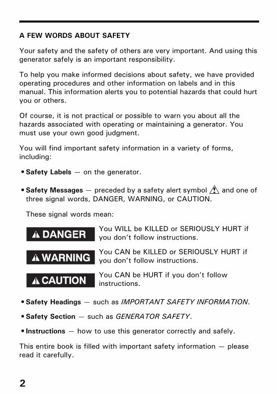
A FEW WORDS ABOUT SAFETY
Your safety and the safety of others are very important. And using this generator safely is an important responsibility.
To help you make informed decisions about safety, we have provided operating procedures and other information on labels and in this manual. This information alerts you to potential hazards that could hurt you or others.
Of course, it is not practical or possible to warn you about all the hazards associated with operating or maintaining a generator. You must use your own good judgment.
You will find important safety information in a variety of forms, including:
• Safety Labels — on the generator.
• Safety Messages — preceded by a safety alert symbol and one of three signal words, DANGER, WARNING, or CAUTION.
These signal words mean:
• Safety Headings — such as IMPORTANT SAFETY INFORMATION.
• Safety Section — such as GENERATOR SAFETY.
• Instructions — how to use this generator correctly and safely.
This entire book is filled with important safety information — please read it carefully.
You WILL be KILLED or SERIOUSLY HURT if you don’t follow instructions.
You CAN be KILLED or SERIOUSLY HURT if you don’t follow instructions.
You CAN be HURT if you don’t follow instructions.
2

4MZ376000.book 3 ページ 2014年9月25日 木曜日 午前11時46分
CONTENTSGENERATOR SAFETY ..................................................................6
IMPORTANT SAFETY INFORMATION .........................................6Operator Responsibility ..........................................................6Carbon Monoxide Hazards......................................................7Electric Shock Hazards...........................................................8Fire and Burn Hazards ............................................................8Refuel With Care...................................................................9Disposal ...............................................................................9
SAFETY LABEL LOCATIONS.................................................... 10
CONTROLS & FEATURES ........................................................... 14COMPONENT & CONTROL LOCATIONS.................................... 14CONTROLS ........................................................................... 16
MAIN Switch...................................................................... 16ENGINE START Button......................................................... 16Starter Grip ........................................................................ 17Eco-Throttle Switch............................................................. 17Folding Handle .................................................................... 18Maintenance Covers ............................................................ 19
FEATURES ............................................................................ 20Ground Terminal ................................................................. 20OUTPUT Indicator ............................................................... 21OVERLOAD ALARM Indicator ............................................... 21OIL ALERT/CHECK Indicator ................................................. 22i-Monitor ............................................................................ 23Fuel Gauge ......................................................................... 26
BEFORE OPERATION ................................................................. 27ARE YOU READY TO GET STARTED?....................................... 27
Knowledge ......................................................................... 27IS YOUR GENERATOR READY TO GO? ..................................... 27
Check the Engine ................................................................ 28Battery Maintenance Cover................................................... 28
OPERATION.............................................................................. 29SAFE OPERATING PRECAUTIONS ............................................ 29STARTING THE ENGINE .......................................................... 30STOPPING THE ENGINE .......................................................... 33STARTING THE ENGINE with REMOTE CONTROL (Optional part)... 34STOPPING THE ENGINE with REMOTE CONTROL (Optional part) ... 35
3
4MZ376000.book 4 ページ 2014年9月25日 木曜日 午前11時46分
CONTENTS
AC OPERATION ..................................................................... 36AC Applications .................................................................. 38
ECO-THROTTLE SYSTEM........................................................ 39STANDBY POWER.................................................................. 40
Connections to a Building’s Electrical System ......................... 40System Ground................................................................... 40Special Requirements........................................................... 41
SERVICING YOUR GENERATOR .................................................. 42THE IMPORTANCE OF MAINTENANCE ..................................... 42MAINTENANCE SAFETY ......................................................... 43
Safety Precautions .............................................................. 43MAINTENANCE SCHEDULE ..................................................... 44REFUELING............................................................................ 45FUEL RECOMMENDATIONS..................................................... 46ENGINE OIL LEVEL CHECK ...................................................... 47ENGINE OIL CHANGE ............................................................. 48ENGINE OIL RECOMMENDATIONS ........................................... 49AIR CLEANER SERVICE........................................................... 50FOAM AIR FILTER CLEANING .................................................. 51SPARK PLUG SERVICE............................................................ 52SPARK ARRESTER SERVICE .................................................... 54BATTERY SERVICE................................................................. 55FUSE .................................................................................... 59
STORAGE................................................................................. 60STORAGE PREPARATION........................................................ 60
Cleaning............................................................................. 60Fuel................................................................................... 60Engine Oil........................................................................... 62Battery .............................................................................. 62
STORAGE PRECAUTIONS ....................................................... 63REMOVAL FROM STORAGE .................................................... 63
TRANSPORTING ....................................................................... 64
4

4MZ376000.book 5 ページ 2014年9月25日 木曜日 午前11時46分
CONTENTS
TAKING CARE OF UNEXPECTED PROBLEMS................................ 66ENGINE WILL NOT START....................................................... 66ENGINE LACKS POWER .......................................................... 67NO POWER AT THE AC RECEPTACLES .................................... 67
TECHNICAL INFORMATION........................................................ 68Serial Number Location ........................................................ 68Specifications ..................................................................... 69
ASSEMBLY............................................................................... 70SAFETY ................................................................................ 70
The Importance of Proper Assembly ...................................... 70Important Safety Precautions................................................ 71
ASSEMBLY............................................................................ 72Unpacking .......................................................................... 72Loose Parts ........................................................................ 72Wheel Kit Installation ........................................................... 73Battery .............................................................................. 74Engine Oil........................................................................... 75Fuel................................................................................... 75Battery Voltage................................................................... 76
BEFORE OPERATION .............................................................. 76
OPTIONAL PARTS..................................................................... 77REMOTE CONTROL KIT (R, U type only) ................................... 77HANGER KIT ......................................................................... 79
5

4MZ376000.book 6 ページ 2014年9月25日 木曜日 午前11時46分
GENERATOR SAFETY
IMPORTANT SAFETY INFORMATION
Honda generators are designed for use with electrical equipment that has suitable power requirements. Other uses can result in injury to the operator or damage to the generator and other property. Most injuries or property damage can be prevented if you follow all instructions in this manual and on the generator. The most common hazards are discussed below, along with the best way to protect yourself and others.
• Never attempt to modify the generator. It can cause an accident as well as damage to the generator and appliances.– Do not connect an extension to the muffler.– Do not modify the intake system.– Do not adjust the governor.– Do not remove the control panel or do not change the wiring of the
control panel.
Operator Responsibility• Know how to stop the generator quickly in case of emergency.
• Understand the use of all generator controls, output receptacles, and connections.
• Be sure that anyone who operates the generator receives proper instruction. Do not let children operate the generator without parental supervision.
• Be sure to observe the instructions in this manual for how to use the generator and maintenance information. Ignoring or improperly following the instructions can cause an accident such as an electric shock, and the condition of the exhaust gas may deteriorate.– Obey all applicable laws and regulations where the generator is used.– Gasoline and Oil is toxic. Follow the instructions provided by each
manufacturer before use.– Place the generator on a firm level place before operation.– Do not operate the generator with any cover removed. You may get
your hand or foot caught in the generator and it may cause accident.
– Consult your authorized Honda dealer for disassembly and service of the generator that are not covered in this manual.
6

4MZ376000.book 7 ページ 2014年9月25日 木曜日 午前11時46分
GENERATOR SAFETY
Carbon Monoxide HazardsA generator's exhaust contains toxic carbon monoxide, which you cannot see or smell. Breathing carbon monoxide can KILL YOU IN MINUTES. To avoid carbon monoxide poisoning, follow these instructions when operating a generator:
• Only run a generator OUTSIDE, far away from windows, doors, and vents.
• Never operate a generator inside a house, garage, basement, crawl space, or any enclosed or partially enclosed space.
• Never operate a generator near open doors or windows.
• Get fresh air and seek medical attention immediately if you suspect you have inhaled carbon monoxide.
Early symptoms of carbon monoxide exposure include headache, fatigue, shortness of breath, nausea, and dizziness. Continued exposure to carbon monoxide can cause loss of muscular coordination, loss of consciousness, and then death.
7

4MZ376000.book 8 ページ 2014年9月25日 木曜日 午前11時46分
GENERATOR SAFETY
Electric Shock HazardsThe generator produces enough electric power to cause a serious shock or electrocution if misused.
• Do not use in wet conditions. Keep the generator dry.– Do not use in the rain or snow.– Do not use near a pool or a sprinkler system.– Do not use when your hands are wet.
• If the generator is stored outdoors, unprotected from the weather, all of the electrical components on the control panel before each use. Moisture or ice can cause a malfunction or short circuit in electrical components that could result in electrocution.
• Do not connect to a building’s electrical system unless an isolation switch has been installed by a qualified electrician.
Fire and Burn HazardsThe exhaust system gets hot enough to ignite some materials.• Keep the generator at least 1 meter away from buildings and other
equipment during operation.• Do not enclose the generator in any structure.• Keep flammable materials away from the generator.
The muffler becomes very hot during operation and remains hot for a while after stopping the engine. Be careful not to touch the muffler while it is hot. Let the engine cool before storing the generator indoors.
8

4MZ376000.book 9 ページ 2014年9月25日 木曜日 午前11時46分
GENERATOR SAFETY
Refuel With CareGasoline is extremely flammable, and gasoline vapor can explode.• Do not refuel during operation.• Allow the engine to cool if it has been in operation.• Refuel only outdoors in a well-ventilated area and on a level surface.• Never smoke near gasoline, and keep other flames and sparks away.• Do not overfill the fuel tank.• Make sure that any spilled fuel has been wiped up before starting the
engine.• Always store gasoline in an approved container.
DisposalTo protect the environment, do not dispose of the used generator, battery, engine oil, etc. carelessly by leaving them in the waste.Observe the local laws or regulations or consult your authorized Honda generator dealer to dispose of these parts.
Please dispose of used motor oil in a manner that is compatible with the environment. We suggest you take it in a sealed container to your local service station for reclamation. Do not throw it in the trash or pour it on the ground.
An improperly disposed battery can hurt the environment. Always confirm local regulations for battery disposal. Contact your Honda servicing dealer for a replacement.
9

4MZ376000.book 10 ページ 2014年9月25日 木曜日 午前11時46分
GENERATOR SAFETY
SAFETY LABEL LOCATIONS
These labels warn you of potential hazards that can cause serious injury. Read them carefully. If a label comes off or becomes hard to read, contact your authorized Honda servicing dealer for a replacement.
R, RA types
READ OWNER’S MANUAL EXHAUST CAUTION
CONNECT CAUTION
FUEL CAUTION
HOT CAUTION
10

4MZ376000.book 11 ページ 2014年9月25日 木曜日 午前11時46分
GENERATOR SAFETY
• Honda generator is designed to give safe and dependable service if operated according to instructions.Read and understand the Owner's Manual before operating the generator. Failure to do so could result in personal injury or equipment damage.
• Gasoline is highly flammable and explosive. Turn the engine off and let it cool before refueling.
• Exhaust contains poisonous carbon monoxide, a colorless, odorless gas. Breathing carbon monoxide can cause loss of consciousness and may lead to death.
• If you run the generator in an area that is confined, or even partially enclosed area, the air you breathe could contain a dangerous amount of exhaust gas.
• Never run your generator inside a garage, house or near open windows or doors.
11

4MZ376000.book 12 ページ 2014年9月25日 木曜日 午前11時46分
GENERATOR SAFETY
• Improper connections to a building’s electrical system can allow current from the generator to backfeed into the utility lines.Such backfeed may electrocute utility company workers or others who contact the lines during a power outage, and the generator may explode, burn, or cause fires when utility power is restored.Consult the utility company or a qualified electrician prior to making any power connections.
• A hot exhaust system can cause serious burns. Avoid contact if the engine has been running.
12

4MZ376000.book 13 ページ 2014年9月25日 木曜日 午前11時46分
GENERATOR SAFETY
U type
13

4MZ376000.book 14 ページ 2014年9月25日 木曜日 午前11時46分
CONTROLS & FEATURES
COMPONENT & CONTROL LOCATIONS
Use the illustrations on these pages to locate and identify the most frequently used controls.
OVERLOAD ALARM INDICATOR
OIL ALERT/CHECK INDICATOR
i-MONITOR BUTTON
ECO-THROTTLE SWITCHAC RECEPTACLES
OUTPUT INDICATOR
i-MONITOR
ENGINE START BUTTON
MAIN SWITCH
AC RECEPTACLES
R type
U type RA type
AC RECEPTACLES
14

4MZ376000.book 15 ページ 2014年9月25日 木曜日 午前11時46分
CONTROLS & FEATURES
FUEL GAUGE
RIGHT MAINTENANCE COVER
OIL DRAIN PLUG
MUFFLER TIP
FUEL TANK CAP
STARTER GRIP
OIL FILLER CAP
GROUND TERMINAL
STANDHANDLE
BATTERY(inside batterymaintenance cover)
FUSE(inside battery maintenance cover)
WHEEL
LEFT MAINTENANCE COVER
AIR CLEANER
SPARK PLUG INSPECTION COVER
15

4MZ376000.book 16 ページ 2014年9月25日 木曜日 午前11時46分
CONTROLS & FEATURES
CONTROLS
MAIN SwitchThe MAIN switch controls the ignition system.
OFF – Stops the engine. The main switch key can be removed/inserted.
ON – Running position, and for starting with the ENGINE START button or recoil starter, and for using the remote control kit (optional part: R, U type only).
ENGINE START ButtonWith the MAIN switch in the ON position, press and release the ENGINE START button to start the engine.
MAIN SWITCH
ON
OFF
ENGINE START BUTTON
16

4MZ376000.book 17 ページ 2014年9月25日 木曜日 午前11時46分
CONTROLS & FEATURES
Starter GripUsed when the battery voltage is too low to turn the starter motor. Pulling the starter grip operates the recoil starter to start the engine.
• Do not exceed 20 degrees from horizontal when pulling the starter grip.
• Do not allow the starter grip to snap back against the engine. Return it gently to prevent damage to the starter.
• Do not let the starter rope rub against the generator body, or the rope will wear out prematurely.
Eco-Throttle SwitchThe Eco-Throttle system automatically reduces engine speed when all loads are turned off or disconnected. When appliances are turned on or reconnected, the engine returns to the proper speed to power theelectrical load.
If high electrical loads are connected simultaneously, turn the Eco-Throttle switch to the OFF position to reduce voltage changes.
ON – Recommended to minimize fuel consumption and further reduce noise levels when a reduced load or no load is applied to the generator.
OFF – The Eco-Throttle system does not operate. Generator operates at full speed.
STARTER GRIP
20°
ECO-THROTTLE SWITCH
OFF ON
17

4MZ376000.book 18 ページ 2014年9月25日 木曜日 午前11時46分
CONTROLS & FEATURES
Folding HandleThe foldable handle makes the generator easy to push and should be folded when the generator is stationary. Do not rest objects on the extended handle.
To Extend The HandleLift handle upward. Lock levers will lock and secure the handle into place.
To Fold The Handle1.Press both handle lock levers downward.2.Lower the handle.
HANDLE
Handle in pushing position
Handle in stationary position
HANDLE LOCK LEVER
18

4MZ376000.book 19 ページ 2014年9月25日 木曜日 午前11時46分
CONTROLS & FEATURES
Maintenance CoversMaintenance cover location.
Be sure the maintenance covers are closed while the generator is running.
Running the generator with maintenance cover(s) open will adversely affect the engine performance, and will cause the generator to overheat.
To open:Turn the latch 90° counterclockwise.
To close:Turn the latch 90° clockwise to lock while pushing the cover.
LATCH LATCH
LEFT MAINTENANCE COVER• Spark plug inspection/replacement• Air cleaner inspection/cleaning
LATCH
RIGHT MAINTENANCE COVER• Engine oil level check• Engine oil change• Use recoil starter
Push the cover closed and turn the latch.
19
4MZ376000.book 20 ページ 2014年9月25日 木曜日 午前11時46分
CONTROLS & FEATURES
FEATURES
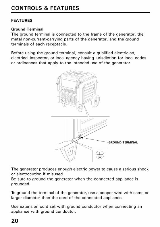
Ground TerminalThe ground terminal is connected to the frame of the generator, the metal non-current-carrying parts of the generator, and the ground terminals of each receptacle.
Before using the ground terminal, consult a qualified electrician, electrical inspector, or local agency having jurisdiction for local codes or ordinances that apply to the intended use of the generator.
The generator produces enough electric power to cause a serious shock or electrocution if misused.Be sure to ground the generator when the connected appliance is grounded.
To ground the terminal of the generator, use a cooper wire with same or larger diameter than the cord of the connected appliance.
Use extension cord set with ground conductor when connecting an appliance with ground conductor.
GROUND TERMINAL
20

4MZ376000.book 21 ページ 2014年9月25日 木曜日 午前11時46分
CONTROLS & FEATURES
OUTPUT IndicatorThe green OUTPUT indicator is illuminated when the generator is operating normally. It indicates that the generator is producing electrical power at the receptacles.
OVERLOAD ALARM IndicatorIf the generator is overloaded, or if there is a short circuit in a connected appliance, or if the inverter is overheated, the red OVERLOAD ALARM indicator will go ON. When the generator is operating overloaded, the red OVERLOAD ALARM indicator will stay ON and, after about five seconds, current to the connected appliance(s) will shut off, and the green OUTPUT indicator will go OFF.
OUTPUT INDICATOR (GREEN)
OVERLOAD ALRAM INDICATOR (RED)
21
4MZ376000.book 22 ページ 2014年9月25日 木曜日 午前11時46分
CONTROLS & FEATURES
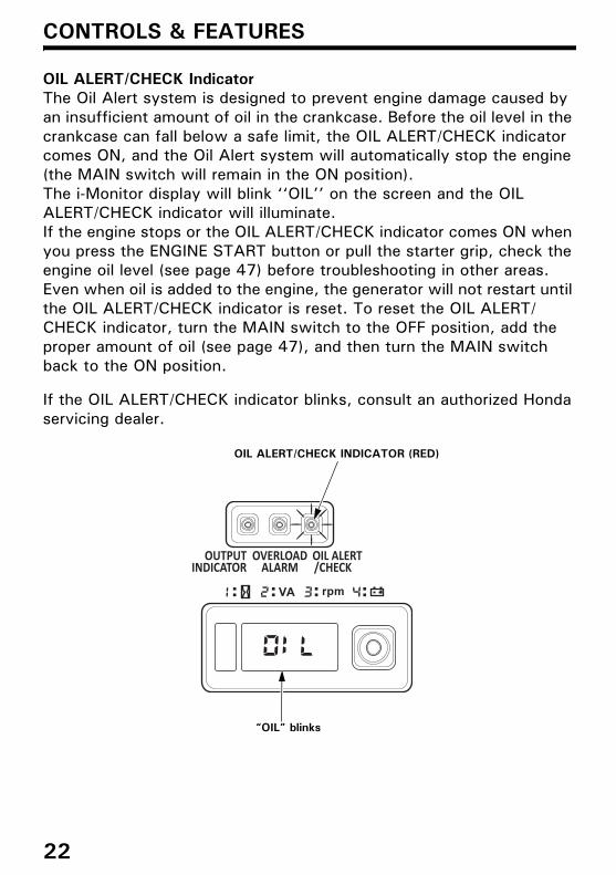
OIL ALERT/CHECK IndicatorThe Oil Alert system is designed to prevent engine damage caused by an insufficient amount of oil in the crankcase. Before the oil level in the crankcase can fall below a safe limit, the OIL ALERT/CHECK indicator comes ON, and the Oil Alert system will automatically stop the engine (the MAIN switch will remain in the ON position).The i-Monitor display will blink ‘‘OIL’’ on the screen and the OIL ALERT/CHECK indicator will illuminate.If the engine stops or the OIL ALERT/CHECK indicator comes ON when you press the ENGINE START button or pull the starter grip, check the engine oil level (see page 47) before troubleshooting in other areas.Even when oil is added to the engine, the generator will not restart until the OIL ALERT/CHECK indicator is reset. To reset the OIL ALERT/CHECK indicator, turn the MAIN switch to the OFF position, add the proper amount of oil (see page 47), and then turn the MAIN switch back to the ON position.
If the OIL ALERT/CHECK indicator blinks, consult an authorized Honda servicing dealer.
OIL ALERT/CHECK INDICATOR (RED)
“OIL” blinks
22

4MZ376000.book 23 ページ 2014年9月25日 木曜日 午前11時46分
CONTROLS & FEATURES
i-MonitorThe i-Monitor is a user interface that allows the operator to view (when the generator is running) total operating time in hours, generator output, engine RPM, battery voltage, and error messages. The different display modes are selected by pressing the i-Monitor button.
i-Monitor at StartupDuring start up, the i-Monitor display and all three indicators will simultaneously blink once. The condition of the i-Monitor display and all three indicators can be checked. Once the generator is running, the green OUTPUT indicator and the i-Monitor display will remain lit.
Display Backlight FlashesIf the key is left in the ON position for over 30 seconds without starting the engine, the display will start to flash.
i-Monitor DisplayThe i-Monitor display is divided into two screens. The single-digit screen displays the i-Monitor mode, which is represented by a number 1 through 4. The four-digit screen displays the four mode values or any activated error messages.
i-Monitor Display Mode 1 – Total Operating HoursThis mode displays the total operating hours of the generator. When the generator is running, the total operating time accumulates. If the total operating time is less than one hour, the numeric display will be ‘‘0.’’ When the operating time is one hour or greater, the display will be ‘‘1’’ or ‘‘2’’ and so on. Base the generator’s maintenance schedule on the accumulated time displayed.
SINGLE-DIGIT SCREEN DISPLAY i-MONITOR BUTTON
FOUR-DIGIT SCREEN DISPLAY
23

4MZ376000.book 24 ページ 2014年9月25日 木曜日 午前11時46分
CONTROLS & FEATURES
i-Monitor Display Mode 2 – Power OutputThis mode displays an approximate generator output on the display screen. The output is expressed in VA (volt-amperes). The output value is not an exact measurement and should be regarded as a reference only. Power output will not display until a load is connected to the generator.
i-Monitor Display Mode 3 – Engine RPMWhen the i-Monitor is in this mode, the engine’s speed, expressed in revolutions-per-minute (RPM), is displayed.
i-Monitor Display Mode 4 – Battery VoltageThis mode displays the battery condition, expressed in Volts DC.
24

4MZ376000.book 25 ページ 2014年9月25日 木曜日 午前11時46分
CONTROLS & FEATURES
i-Monitor Low Battery MessageIf the ENGINE START button is pressed and ‘‘batt’’ is blinked on thei-Monitor display, the battery voltage is too low to operate the engine’s electric starter. Use the recoil starter to start the generator. Have the battery recharged and checked (see page 58).
i-Monitor System Error MessagesIf the generator has a system malfunction, it will blink an error message on the i-Monitor display. During remote control operation, an E-01 error message may display if the ENGINE START button is pressed for more than 10 seconds. With an E-01 error message, the engine will stay running and the electrical output may stay constant.Normal remote control operation will be restored after the E-01 error message clears automatically. If the E-01 error message does not clear automatically or if any other error message displays, contact an authorized Honda servicing dealer.
“batt” blinks
OIL ALERT/CHECK INDICATOR
ERROR MESSAGE(Example: E-01)“E-01” blinks
25

4MZ376000.book 26 ページ 2014年9月25日 木曜日 午前11時46分
CONTROLS & FEATURES
Fuel GaugeThe fuel gauge is a mechanical device that measures the fuel level in the tank. The red indicator in the window will reference the level in relation to full or empty. To provide increased operating time, start with a full tank before operation. Check the fuel level with the generator on a level surface. Always refuel with the engine OFF and cool.
FULL
FUEL GAUGE
EMPTY
26
4MZ376000.book 27 ページ 2014年9月25日 木曜日 午前11時46分
BEFORE OPERATION
ARE YOU READY TO GET STARTED?
Your safety is your responsibility. A little time spent in preparation will significantly reduce your risk of injury.
KnowledgeRead and understand this manual. Know what the controls do and how to operate them.
Familiarize yourself with the generator and its operation before you begin using it. Know how to quickly shut off the generator in case of an emergency.
If the generator is being used to power appliances, be sure that they do not exceed the generator’s load rating (see page 38).
IS YOUR GENERATOR READY TO GO?
For your safety, to ensure compliance with environmental regulations, and to maximize the service life of your equipment, it is very important to take a few moments before you operate the generator to check its condition. Be sure to take care of any problem you find, or have your authorized Honda servicing dealer correct it, before you operate the generator.
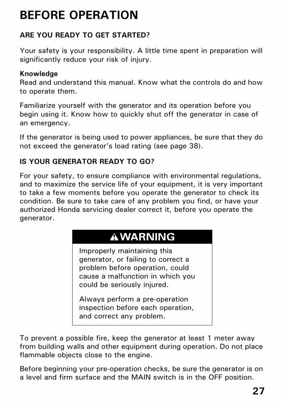
To prevent a possible fire, keep the generator at least 1 meter away from building walls and other equipment during operation. Do not place flammable objects close to the engine.
Before beginning your pre-operation checks, be sure the generator is on a level and firm surface and the MAIN switch is in the OFF position.
Improperly maintaining this generator, or failing to correct a problem before operation, could cause a malfunction in which you could be seriously injured.
Always perform a pre-operation inspection before each operation, and correct any problem.
27

4MZ376000.book 28 ページ 2014年9月25日 木曜日 午前11時46分
BEFORE OPERATION
Check the Engine
• Before each use, look around and underneath the engine for signs of oil or gasoline leaks.
• Check the engine oil level (see page 47). A low engine oil level will cause the Oil Alert system to shut down the engine.
• Check the air filters (see page 50). Dirty air filters will restrict air flow to the fuel system, reducing engine and generator performance.
• Check the fuel level (see page 45). Starting with a full tank will help to eliminate or reduce operating interruptions for refueling.
Battery Maintenance CoverNever operate the generator with the battery maintenance cover open, as poor engine and generator performance will result.
BATTERY MAINTENANCE COVER
28

4MZ376000.book 29 ページ 2014年9月25日 木曜日 午前11時46分
OPERATION
SAFE OPERATING PRECAUTIONS
Before operating the generator for the first time, review chapters GENERATOR SAFETY (see page 6) and BEFORE OPERATION (see page 27).
For your safety, do not operate the generator in an enclosed area such as a garage. Your generator’s exhaust contains poisonous carbon monoxide gas that can collect rapidly in an enclosed area and cause illness or death.
Before connecting an AC appliance or power cord to the generator:
• Use grounded 3-prong extension cords, tools, and appliances, or double-insulated tools and appliances.
• Inspect cords and plugs, and replace if damaged.• Make sure that the appliance is in good working order. Faulty
appliances or power cords can create a potential for electric shock.• Make sure the electrical rating of the tool or appliance does not
exceed the rated power of the generator or the receptacle being used.
• Operate the generator at least 1 meter away from buildings and other equipment.
• Do not operate the generator in an enclosed structure.• Do not place flammable objects close to the engine.
Exhaust contains poisonous carbon monoxide gas that can build up to dangerous levels in closed areas. Breathing carbon monoxide can cause unconsciousness or death.
Never run the generator in a closed, or even partly closed area where people may be present.
29

4MZ376000.book 30 ページ 2014年9月25日 木曜日 午前11時46分
OPERATION
Frequency of UseIf your generator will be used on an infrequent or intermittent basis, (more than 4 weeks before next use), please refer to the Battery Service section of the SERVICING YOUR GENERATOR (see page 55) and the Fuel section of the STORAGE chapter (see page 60) for additional information regarding battery and fuel deterioration.
STARTING THE ENGINETo prevent a possible fire, keep the generator at least 1 meter away from building walls and other equipment during operation. Do not place flammable objects close to the engine.
• Operating this generator less than 1 meter from a building or other obstruction can cause overheating and damage the generator.
• For proper cooling, allow at least 1 meter of empty space above and around the generator.Keep all cooling holes open and clear of debris, mud, water, etc. Cooling holes are located on the control panel and the bottom of the generator. If the cooling holes are blocked, the generator may overheat and damage the engine, inverter, or windings.
Refer to SAFE OPERATING PRECAUTIONS on page 29 and perform the IS YOUR GENERATOR READY TO GO? checks (see page 27).
Refer to AC OPERATION (see page 36) for connecting loads to the generator.
1.Make sure that all appliances are disconnected from the AC receptacles.
30

4MZ376000.book 31 ページ 2014年9月25日 木曜日 午前11時46分
OPERATION
2.Make sure the Eco-Throttle switch is in the OFF position, or more time will be required for warm-up.If you wish to use the Eco-Throttle system, turn the Eco-Throttle switch to the ON position after the engine has warmed up for 2 or 3 minutes.
3.Turn the MAIN switch to the ON position.
4.Press and release the ENGINE START button.The ENGINE START button functions for 5 seconds. As soon as the engine starts, the starter will stop automatically.
If the engine fails to start, wait at least 10 seconds before operating the starter again.
Do not leave the MAIN switch in the ON position when the generator is not operating or the battery will be drained. Turn the MAIN switch to the OFF position when not in use.
ONOFF
ECO-THROTTLE SWITCH
MAIN SWITCH
ENGINE START BUTTON
ON
OFF
31
4MZ376000.book 32 ページ 2014年9月25日 木曜日 午前11時46分
OPERATION
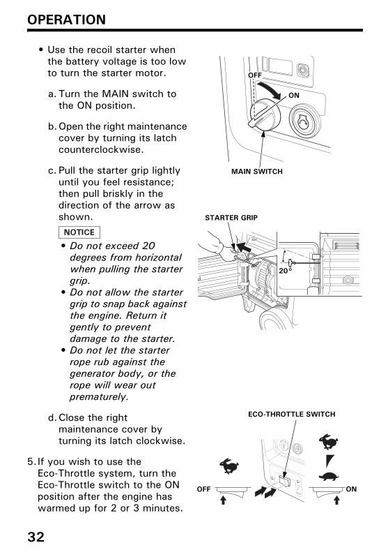
• Use the recoil starter when the battery voltage is too low to turn the starter motor.
a. Turn the MAIN switch to the ON position.
b.Open the right maintenance cover by turning its latch counterclockwise.
c. Pull the starter grip lightly until you feel resistance; then pull briskly in the direction of the arrow as shown.
• Do not exceed 20 degrees from horizontal when pulling the starter grip.
• Do not allow the starter grip to snap back against the engine. Return it gently to prevent damage to the starter.
• Do not let the starter rope rub against the generator body, or the rope will wear out prematurely.
d.Close the right maintenance cover by turning its latch clockwise.
5.If you wish to use the Eco-Throttle system, turn the Eco-Throttle switch to the ON position after the engine has warmed up for 2 or 3 minutes.
MAIN SWITCH
ON
20°
STARTER GRIP
ECO-THROTTLE SWITCH
OFF ON
OFF
32

4MZ376000.book 33 ページ 2014年9月25日 木曜日 午前11時46分
OPERATION
STOPPING THE ENGINE
To stop the engine in an emergency, simply turn the MAIN switch to the OFF position.Under normal conditions, use the following procedure.
1.Turn the MAIN switch to the OFF position.
2.Unplug all appliances from the generator AC receptacles.
MAIN SWITCH
ON
OFF
33

4MZ376000.book 34 ページ 2014年9月25日 木曜日 午前11時46分
OPERATION
STARTING THE ENGINE with REMOTE CONTROL (Optional part)R, U type only
1.Turn the MAIN switch of the generator to the ON position.
2.Turn the MAIN switch of the remote control to the ON position.
3.Press and release the ENGINE START button.The ENGINE START button functions for 5 seconds. As soon as the engine starts, the starter will stop automatically.The pilot lamp comes on when the engine starts.
If the engine fails to start, wait at least 10 seconds before operating the starter again.
MAIN SWITCH
ON
OFF
PILOT LAMP ENGINE START BUTTON
MAIN SWITCHON
OFF
34

4MZ376000.book 35 ページ 2014年9月25日 木曜日 午前11時46分
OPERATION
STOPPING THE ENGINE with REMOTE CONTROL (Optional part)R, U type only
1.Turn the MAIN switch of the remote control to the OFF position.
MAIN SWITCH ON
OFF
35

4MZ376000.book 36 ページ 2014年9月25日 木曜日 午前11時46分
OPERATION
AC OPERATION
If an appliance begins to operate abnormally, becomes sluggish, or stops suddenly, turn it off immediately. Disconnect the appliance, and determine whether the problem is in the appliance or the rated load capacity of the generator has been exceeded.
Substantial overloading that continuously lights the red OVERLOAD ALARM indicator may damage the generator. Marginal overloading that temporarily lights the red OVERLOAD ALARM indicator may shorten the service life of the generator.
1.Start the engine and make sure the green OUTPUT indicator comes on.
2.Plug in the appliance.Most motorized appliances require more than their rated wattage for startup.
OUTPUT INDICATOR (GREEN)
PLUG
36
4MZ376000.book 37 ページ 2014年9月25日 木曜日 午前11時46分
OPERATION
If the generator is overloaded, or if there is a short circuit in a connected appliance, or if the inverter is overheated, the red OVERLOAD ALARM indicator will come ON. The red OVERLOAD ALARM indicator will stay ON and, after about five seconds, current to the connected appliance(s) will shut off, and the green OUTPUT indicator will go OFF. Stop the engine and investigate the problem.
Determine if the cause is a short circuit in a connected appliance, an overload, or an overheated inverter. Correct the problem and restart the generator.
Before connecting an appliance to the generator, make sure that it is in good order and that its electrical rating does not exceed that of the generator. Then start the generator and connect the appliance power cord.
When an electric motor is started, the red OVERLOAD ALARM indicator may come on. This is normal if the red OVERLOAD ALARM indicator goes OFF after about five seconds. If the red OVERLOAD ALARM indicator stays ON, consult an authorized Honda servicing dealer.
37

4MZ376000.book 38 ページ 2014年9月25日 木曜日 午前11時46分
OPERATION
AC ApplicationsBefore connecting an appliance or power cord to the generator:
• Make sure that it is in good working order. Faulty appliances or power cords can create a potential for electrical shock.
• If an appliance begins to operate abnormally, becomes sluggish, or stops suddenly, turn it off immediately. Disconnect the appliance, and determine whether the problem is the appliance or the rated load capacity of the generator has been exceeded.
Most appliance motors require more than their rated wattage for startup.Make sure the electrical rating of the tool or appliance does not exceed the maximum power rating of the generator.
Maximum power is:
7.0 kVA
For continuous operation, do not exceed the rated power.Rated power is:
5.5 kVA
In either case, the total power requirements (VA) of all appliances connected must be considered. Appliance and power tool manufacturers usually list rating information near the model number or serial number.
38

4MZ376000.book 39 ページ 2014年9月25日 木曜日 午前11時46分
OPERATION
ECO-THROTTLE SYSTEM
With the switch in the ON position, engine speed is automatically lowered when loads are reduced, turned off, or disconnected. When appliances are turned on or reconnected, the engine returns to the proper speed to power the electrical load. In the OFF position, the Eco-Throttle system does not operate.
Appliances with large start-up power demands may not allow the engine to reach normal operating rpm when they are connected to the generator. Turn the Eco-Throttle switch to the OFF position and connect the appliance to the generator. If the engine still will not reach normal operating speed, check that the appliance does not exceed the rated load capacity of the generator.
If high electrical loads are connected simultaneously, turn the Eco-Throttle switch to the OFF position to reduce voltage changes.
The Eco-Throttle system is not effective for use with appliances or tools that require only momentary power. If the tool or appliance will be turned ON and OFF quickly, the Eco-Throttle switch should be in the OFF position.
ECO-THROTTLE SWITCH
OFF ON
39

4MZ376000.book 40 ページ 2014年9月25日 木曜日 午前11時46分
OPERATION
STANDBY POWER
Connections to a Building’s Electrical SystemConnections for standby power to a building's electrical system must be made by a qualified electrician. The connection must isolate the generator power from utility power, and must comply with all applicable laws and electrical codes.
In some areas, generators are required by law to be registered with local utility companies. Check local regulations for proper registration and use procedures.
System GroundThis generator has a system ground that connects generator frame components to ground terminals in the AC output receptacles. The system ground is not connected to the AC neutral wire.
Improper connections to a building’s electrical system can allow current from the generator to backfeed into the utility lines.
Such backfeed may electrocute utility company workers or others who contact the lines during a power outage, and the generator may explode, burn, or cause fires when utility power is restored.
Consult the utility company or a qualified electrician prior to making any power connections.
40

4MZ376000.book 41 ページ 2014年9月25日 木曜日 午前11時46分
OPERATION
Special RequirementsThere may be applicable laws, local codes, or ordinances that apply to the intended use of the generator. Please consult a qualified electrician, electrical inspector, or the local agency having jurisdiction.
• In some areas, generators are required to be registered with local utility companies.
• If the generator is used at a construction site, there may be additional regulations that must be observed.
41

4MZ376000.book 42 ページ 2014年9月25日 木曜日 午前11時46分
SERVICING YOUR GENERATOR
THE IMPORTANCE OF MAINTENANCE
Good maintenance is essential for safe, economical, and trouble-free operation. It will also help reduce air pollution.
To help you properly care for your generator, the following pages include a maintenance schedule, routine inspection procedures, and simple maintenance procedures using basic hand tools. Other service tasks that are more difficult or require special tools are best handled by professionals and are normally performed by a Honda technician or other qualified mechanic.
The maintenance schedule applies to normal operating conditions. If you operate your generator under unusual conditions, such as sustained high-load or high-temperature operation, or use it in dusty conditions, consult your authorized Honda servicing dealer for recommendations applicable to your individual needs and use.
Remember that an authorized Honda servicing dealer knows your generator best and is fully equipped to maintain and repair it.
To ensure the best quality and reliability, use only new, Honda Genuine parts or their equivalents for repair and replacement.
Improper maintenance, or failure to correct a problem before operation, can cause a malfunction in which you can be seriously hurt or killed.
Always follow the inspection and maintenance recommendations and schedules in this owner’s manual.
42

4MZ376000.book 43 ページ 2014年9月25日 木曜日 午前11時46分
SERVICING YOUR GENERATOR
MAINTENANCE SAFETY
Some of the most important safety precautions follow. However, we cannot warn you of every conceivable hazard that can arise in performing maintenance. Only you can decide whether or not you should perform a given task.
Safety Precautions
Make sure the engine is off before you begin any maintenance or repairs. This will eliminate several potential hazards:
–Carbon monoxide poisoning from engine exhaust.Operate outside away from open windows or doors.
–Burns from hot parts.Let the engine and exhaust system cool before touching.
–Injury from moving parts.Do not run the engine unless instructed to do so.
• Read the instructions before you begin, and make sure you have the tools and skills required.
• To reduce the possibility of fire or explosion, be careful when working around gasoline. Use only a non-flammable solvent, not gasoline, to clean parts. Keep cigarettes, sparks, and flames away from all fuel-related parts.
Failure to properly follow maintenance instructions and precautions can cause you to be seriously hurt or killed.
Always follow the procedures and precautions in the owner’s manual.
43

4MZ376000.book 44 ページ 2014年9月25日 木曜日 午前11時46分
SERVICING YOUR GENERATOR
MAINTENANCE SCHEDULE
NOTE:(*) Replace paper element type only.(1)Service more frequently when used in dusty areas.(2)These items should be serviced by your authorized Honda servicing dealer, unless you have the
proper tools and are mechanically proficient. Refer to the Honda shop manual for service procedures.
(3)For commercial use, log hours of operation to determine proper maintenance intervals.(4) In the event of cracks or fracture in the fuel filter grommet and regulator grommet, replace the
part with a new one.
This generator is equipped with a catalytic converter. If the engine is not properly maintained, the catalyst in the muffler may lose effectiveness.
REGULAR SERVICE PERIOD (3)ITEMPerform at every indicated month or operating hour interval, whichever comes first.
Each use
First month
or 20 hrs.
Every 3 months
or 50 hrs.
Every 6 months
or 100 hrs.
Every year or
300 hrs.
Page
Engine oil Check level o 47Change o o 48
Air cleaner Check o 50Clean o (1) 51Replace o (*) 50
Spark plug Check-adjust o 52Replace o 52
Spark arrester Clean o 54Valve clearance Check-adjust o (2) —Combustion chamber
Clean After every 1,000 hrs. (2) —
Fuel tank Clean Every 2 years or 1,000 hrs. (2) —Fuel filter Change Every 2 years or 1,000 hrs. (2) (4) —Fuel tube Check Every 2 years (Replace if necessary) (2) (4) —
44

4MZ376000.book 45 ページ 2014年9月25日 木曜日 午前11時46分
SERVICING YOUR GENERATOR
REFUELING
With the engine stopped, check the fuel level gauge. Refill the fuel tank if the fuel level is low.
Fuel can damage paint and plastic. Be careful not to spill fuel when filling your fuel tank. Damage caused by spilled fuel is not covered under warranty.
Refuel in a well-ventilated area before starting the engine. If the engine has been running, allow it to cool. Refuel carefully to avoid spilling fuel.Do not fill the fuel tank above the upper level mark (red) on the fuel filter.Never refuel the engine inside a building where gasoline fumes may reach flames or sparks. Keep gasoline away from appliance pilot lights, barbecues, electric appliances, power tools, etc.Spilled fuel is not only a fire hazard, it causes environmental damage. Wipe up spills immediately.
Gasoline is highly flammable and explosive.
You can be burned or seriously injured when handling fuel.
• Stop the engine and keep heat, sparks, and flame away.
• Handle fuel only outdoors.• Wipe up spills immediately.
45

4MZ376000.book 46 ページ 2014年9月25日 木曜日 午前11時46分
SERVICING YOUR GENERATOR
After refueling, reinstall the fuel tank cap securely.
FUEL RECOMMENDATIONS
This engine is certified to operate on regular unleaded gasoline with a Research Octane Number of 89 or higher.Use unleaded gasoline only, or the catalyzer will loose its effectiveness and negatively affect exhaust emissions.
Never use stale or contaminated gasoline or an oil/gasoline mixture. Avoid getting dirt or water in the fuel tank.
You may use regular unleaded gasoline containing no more than 10% ethanol (E10) or 5% methanol by volume. In addition, methanol must contain cosolvents and corrosion inhibitors.
Use of fuels with content of ethanol or methanol greater than shown above may cause starting and/or performance problems. It may also damage metal, rubber, and plastic parts of the fuel system.
Engine damage or performance problems that result from using a fuel with percentages of ethanol or methanol greater than shown above and leaded gasoline are not covered under warranty.
If your equipment will be used on an infrequent basis, please refer to the fuel section of the STORAGE chapter (see page 60) for additional information regarding fuel deterioration.
FULL
FUEL TANK CAP
FUEL GAUGE
EMPTY
UPPER LEVEL MARK (RED)
FUEL FILTER
46
4MZ376000.book 47 ページ 2014年9月25日 木曜日 午前11時46分
SERVICING YOUR GENERATOR
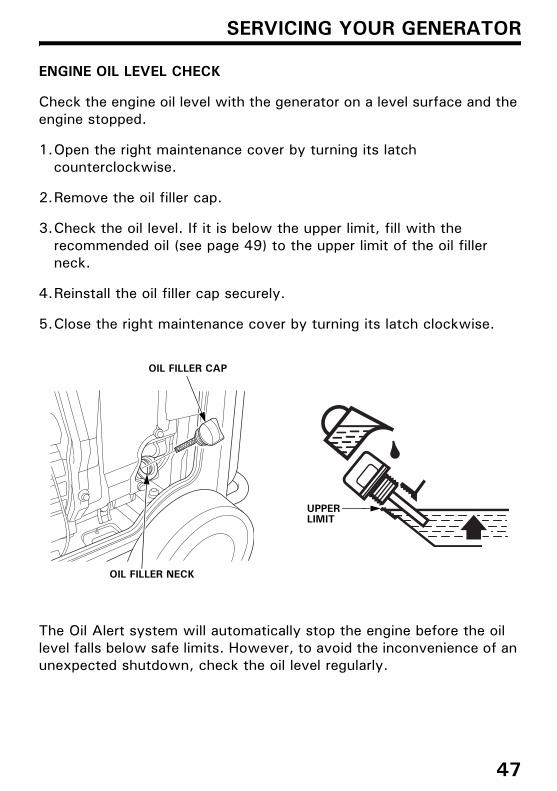
ENGINE OIL LEVEL CHECK
Check the engine oil level with the generator on a level surface and the engine stopped.
1.Open the right maintenance cover by turning its latch counterclockwise.
2.Remove the oil filler cap.
3.Check the oil level. If it is below the upper limit, fill with the recommended oil (see page 49) to the upper limit of the oil filler neck.
4.Reinstall the oil filler cap securely.
5.Close the right maintenance cover by turning its latch clockwise.
The Oil Alert system will automatically stop the engine before the oil level falls below safe limits. However, to avoid the inconvenience of an unexpected shutdown, check the oil level regularly.
OIL FILLER NECK
OIL FILLER CAP
UPPER LIMIT
47

4MZ376000.book 48 ページ 2014年9月25日 木曜日 午前11時46分
SERVICING YOUR GENERATOR
ENGINE OIL CHANGE
Drain the oil while the engine is warm to assure rapid and complete draining.
1.Open the right maintenance cover by turning its latch counterclockwise.
2.Reach under the generator and remove the black rubber seal located below the oil drain plug.
3.Place a suitable container underneath the generator to catch the used oil.
4.Remove the oil filler cap.5.Remove the oil drain plug and sealing washer and allow the oil to
drain completely.6.Reinstall the oil drain plug and a new sealing washer. Tighten the
plug securely.7.Reach under the generator and reinstall the black rubber seal.
Improper disposal of engine oil can be harmful to the environment. If you change your own oil, please dispose of the used oil properly. Put it in a sealed container, and take it to a recycling center. Do not discard it in a trash bin, dump it on the ground, or pour it down the drain.
8.With the generator in a level position, fill with the recommended oil (see page 49) to the upper limit of the oil filler neck.Maximum oil capacity: 1.1 L
9.Reinstall the oil filler cap securely.10.Close the right maintenance cover by turning its latch clockwise.
Wash your hands with soap and water after handling used oil.BLACK RUBBER SEAL SEALING WASHER
(Replace)
OIL FILLER CAP
OIL FILLER CAP
OIL DRAIN PLUG
UPPER LIMIT
48

4MZ376000.book 49 ページ 2014年9月25日 木曜日 午前11時46分
SERVICING YOUR GENERATOR
ENGINE OIL RECOMMENDATIONS
Oil is a major factor affecting engine performance and service life.
Use 4-stroke motor oil that meets or exceeds the requirements for API service category SE or later (or equivalent). Always check the API SERVICE label on the oil container to be sure it includes the letters SE or later (or equivalent).
SAE 10W–30 is recommended for general use. Other viscosities shown in the chart may be used when the average temperature in your area is within the recommended range.
Read the instruction on the oil container before use.
AMBIENT TEMPERATURE
49

4MZ376000.book 50 ページ 2014年9月25日 木曜日 午前11時46分
SERVICING YOUR GENERATOR
AIR CLEANER SERVICE
1.Open the left maintenance cover by turning its latch counterclockwise.
2.Unsnap the air cleaner cover clips; remove the air cleaner cover.
3.Foam air filter:a. Remove the foam air filter from the air cleaner cover.b.Check the foam air filter to be sure it is clean and in good
condition. If the foam air filter is dirty, clean it as described on page 51. Replace the foam air filter if it is damaged.
c. Reinstall the foam air filter in the air cleaner cover.
4.Paper air filter:a. Remove the guide.b. If the paper air filter is dirty, replace it with a new one.
Do not clean the paper air filter.
5.Reinstall the guide and the air cleaner cover.
6.Close the left maintenance cover.
Operating the engine without the air filters, or with a damaged air filters, will allow dirt to enter the engine, causing rapid engine wear.
PAPER AIR FILTER
AIR CLEANER COVER
CLIP
GUIDE
FOAM AIR FILTER
50

4MZ376000.book 51 ページ 2014年9月25日 木曜日 午前11時46分
SERVICING YOUR GENERATOR
FOAM AIR FILTER CLEANING
A dirty foam air filter will restrict air flow to the fuel system, reducing engine performance. If you operate the generator in very dusty areas, clean the foam air filter more frequently than specified in the Maintenance Schedule.
1.Clean the foam air filter in warm soapy water, rinse, and allow to dry thoroughly, or clean in non-flammable solvent and allow to dry.
2.Dip the foam air filter in clean engine oil, and then squeeze out all excess oil. The engine will smoke when started if too much oil is left in the foam air filter.
3.Wipe dirt from the inside of the air cleaner cover using a moist rag. Be careful to prevent dirt from entering the air duct that leads to the fuel system.
Clean Squeeze and DryDo not twist.
Dip in Oil SqueezeDo not twist.
51

4MZ376000.book 52 ページ 2014年9月25日 木曜日 午前11時46分
SERVICING YOUR GENERATOR
SPARK PLUG SERVICE
Recommended spark plugs: BPR6ES (NGK)
To ensure proper engine operation, the spark plug must be properly gapped and free of deposits.
An incorrect spark plug can cause engine damage.
If the engine is hot, allow it to cool before servicing the spark plug.
1.Open the left maintenance cover by turning its latch counterclockwise.
2.Loosen the cover screw and remove the spark plug inspection cover.
3.Disconnect the spark plug cap, and remove any dirt from around the spark plug area.
4.Remove the spark plug with the spark plug wrench.
COVER SCREW
SPARK PLUG INSPECTION COVER
SPARK PLUG WRENCH
SPARK PLUG CAP
52
4MZ376000.book 53 ページ 2014年9月25日 木曜日 午前11時46分
SERVICING YOUR GENERATOR
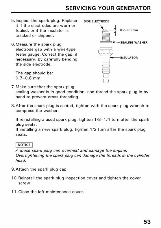
5.Inspect the spark plug. Replace it if the electrodes are worn or fouled, or if the insulator is cracked or chipped.
6.Measure the spark plug electrode gap with a wire-type feeler gauge. Correct the gap, if necessary, by carefully bending the side electrode.
The gap should be:0.7–0.8 mm
7.Make sure that the spark plug sealing washer is in good condition, and thread the spark plug in by hand to prevent cross-threading.
8.After the spark plug is seated, tighten with the spark plug wrench to compress the washer.
If reinstalling a used spark plug, tighten 1/8–1/4 turn after the spark plug seats.If installing a new spark plug, tighten 1/2 turn after the spark plug seats.
A loose spark plug can overheat and damage the engine.Overtightening the spark plug can damage the threads in the cylinder head.
9.Attach the spark plug cap.
10.Reinstall the spark plug inspection cover and tighten the cover screw.
11.Close the left maintenance cover.
SEALING WASHER
0.7–0.8 mm
SIDE ELECTRODE
INSULATOR
53

4MZ376000.book 54 ページ 2014年9月25日 木曜日 午前11時46分
SERVICING YOUR GENERATOR
SPARK ARRESTER SERVICE
If the engine has been running, the muffler will be very hot. Allow the muffler to cool before servicing the spark arrester.
1.Remove the two 5×16 mm pan head screws, and remove the tail pipe and spark arrester.
2.Use a brush to remove carbon deposits from the spark arrester screen.Be careful to avoid damaging the screen.The spark arrester must be free of breaks and tears. Replace the spark arrester if it is damaged.
3.Install the spark arrester in the reverse order of removal.
TAIL PIPE
SPARK ARRESTER
5×16 mm PAN HEAD SCREW (2)
54
4MZ376000.book 55 ページ 2014年9月25日 木曜日 午前11時46分
SERVICING YOUR GENERATOR
BATTERY SERVICE
Your generator’s engine charging system charges the battery while the engine is running. However, if the generator is only used periodically, the battery must be charged monthly to maintain the battery service life.
Emergency Procedures
Eyes – Flush with water from a cup or other container for at least fifteen minutes. (Water under pressure can damage the eye.)Call a physician immediately.
Skin – Remove contaminated clothing. Flush the skin with large quantities of water. Call a physician immediately.
Swallowing – Drink water or milk. Call a physician immediately.
The battery contains sulfuric acid (electrolyte), which is highly corrosive and poisonous. Getting electrolyte in your eyes or on your skin can cause serious burns.
Wear protective clothing and eye protection when working near the battery.KEEP CHILDREN AWAY FROM THE BATTERY.
55
4MZ376000.book 56 ページ 2014年9月25日 木曜日 午前11時46分
SERVICING YOUR GENERATOR
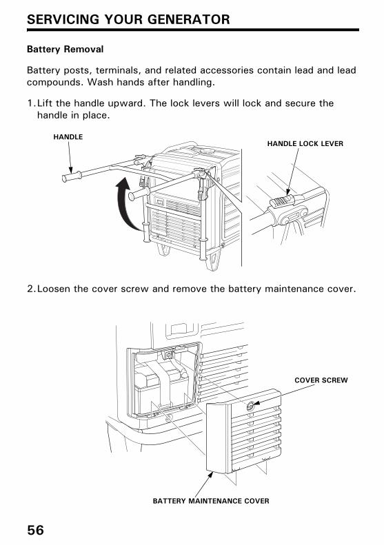
Battery Removal
Battery posts, terminals, and related accessories contain lead and lead compounds. Wash hands after handling.
1.Lift the handle upward. The lock levers will lock and secure the handle in place.
2.Loosen the cover screw and remove the battery maintenance cover.
HANDLEHANDLE LOCK LEVER
COVER SCREW
BATTERY MAINTENANCE COVER
56

4MZ376000.book 57 ページ 2014年9月25日 木曜日 午前11時46分
SERVICING YOUR GENERATOR
3.Remove the negative (–) cable from the battery negative (–) terminal, and then remove the positive (+) cable from the battery positive (+) terminal.
4.Unhook the battery strap from the bottom hook of the generator.
5.Remove the battery.
This symbol on the battery means that this product must not be treated as household waste.
An improperly disposed of battery can be harmful to the environment and human health.Always confirm local regulations for battery disposal.
BATTERY STRAP
NEGATIVE (–) CABLE
POSITIVE (+) CABLE
57
4MZ376000.book 58 ページ 2014年9月25日 木曜日 午前11時46分
SERVICING YOUR GENERATOR
Battery Charging
The battery is rated at 11.2 Ah (ampere-hours). Charging current should equal 10% of the battery’s ampere-hour rating. A battery charger should be used that can be adjusted to deliver 1.1 amps.
1.Connect the battery charger following the manufacturer’s instructions.
2.Charge the battery 5–10 hours.3.Clean the outside of the battery and the battery compartment with a
solution of baking soda and water.
Battery Installation1.Install the battery into the generator.2.Connect the positive (+) cable to the battery positive (+)
terminal first, and tighten the bolt securely.3.Slide the battery boot over the positive (+) cable and terminal.4.Connect the negative (–) cable to the battery negative (–)
terminal, and tighten the bolt securely.5.Install the battery strap.6.Install the battery maintenance cover in the reverse order of removal
(see page 56).Never operate the generator with the battery maintenance cover open, as poor engine and generator performance will result.
The battery gives off explosive hydrogen gas during normal operation.
A spark or flame can cause the battery to explode with enough force to kill or seriously hurt you.
Wear protective clothing and a face shield, or have a skilled mechanic perform the battery maintenance.
58

4MZ376000.book 59 ページ 2014年9月25日 木曜日 午前11時46分
SERVICING YOUR GENERATOR
FUSE
If the fuse is blown, the starter motor will not operate.
In the event of fuse failure, locate the cause of failure and repair it before you continue operation. If the fuse continues to fail, discontinue generator use and consult an authorized Honda servicing dealer.
1.Turn the MAIN switch to the OFF position and remove the key before checking or replacing the fuse.
2.Loosen the cover screw and remove the battery maintenance cover.
3.Remove the fuse holder cover and pull the fuse out.
4.Replace the fuse with a fuse of the same type and rating.Specified fuse: 3 A, 15 A
Never use a fuse with a different rating from that specified. Serious damage to the electrical system or fire may result.
5.Install the fuse holder cover and the battery maintenance cover in the reverse order of removal (see page 56).Never operate the generator with the battery maintenance cover open, as poor engine and generator performance will result.
BATTERY MAINTENANCE COVER
COVER SCREW
FUSE (15 A) FUSE (3 A)
FUSE HOLDER COVER
59

4MZ376000.book 60 ページ 2014年9月25日 木曜日 午前11時46分
STORAGE
STORAGE PREPARATION
Proper storage preparation is essential for keeping your generator trouble-free and looking good. The following steps will help to keep rust and corrosion from impairing your generator’s function and appearance, and will make the engine easier to start when you use the generator again.
CleaningWipe the generator with a moist cloth. After the generator has dried, touch up any damaged paint, and coat other areas that may rust with a light film of oil.
Fuel
Depending on the region where you operate your equipment, fuel formulations may deteriorate and oxidize rapidly. Fuel deterioration and oxidation can occur in as little as 30 days and may cause damage to the fuel system. Please check with your authorized Honda servicing dealer for local storage recommendations.
Gasoline will oxidize and deteriorate in storage. Old gasoline will cause hard starting, and it leaves gum deposits that clog the fuel system. If the gasoline in your generator deteriorates during storage, you may need to have the fuel system components serviced or replaced.The length of time that gasoline can be left in your fuel tank without causing functional problems will vary with such factors as gasoline blend, your storage temperatures, and whether the fuel tank is partially or completely filled. The air in a partially filled fuel tank promotes fuel deterioration. Very warm storage temperatures accelerate fuel deterioration. Fuel deterioration problems may occur within a few months, or even less if the gasoline was not fresh when you filled the fuel tank.
60
4MZ376000.book 61 ページ 2014年9月25日 木曜日 午前11時46分
STORAGE
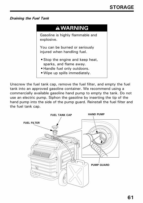
Draining the Fuel Tank
Unscrew the fuel tank cap, remove the fuel filter, and empty the fuel tank into an approved gasoline container. We recommend using a commercially available gasoline hand pump to empty the tank. Do not use an electric pump. Siphon the gasoline by inserting the tip of the hand pump into the side of the pump guard. Reinstall the fuel filter and the fuel tank cap.
Gasoline is highly flammable and explosive.
You can be burned or seriously injured when handling fuel.
• Stop the engine and keep heat, sparks, and flame away.
• Handle fuel only outdoors.• Wipe up spills immediately.
FUEL FILTER
FUEL TANK CAP HAND PUMP
PUMP GUARD
61
4MZ376000.book 62 ページ 2014年9月25日 木曜日 午前11時46分
STORAGE
Engine Oil1.Change the engine oil (see page 48).
2.Remove the spark plug (see page 52).
3.Pour a teaspoon (5 cm3) of clean engine oil into the cylinder.
4.Pull the starter rope several times to distribute the oil in the cylinder.
5.Reinstall the spark plug (see page 53).
6.Slowly pull the starter grip until resistance is felt. At this point, the piston is coming up on its compression stroke and both the intake and exhaust valves are closed. Storing the engine in this position will help to protect it from internal corrosion. Return the starter grip gently.
BatteryCharge the battery before storing the generator (see page 58).
62

4MZ376000.book 63 ページ 2014年9月25日 木曜日 午前11時46分
STORAGE
STORAGE PRECAUTIONS
If your generator will be stored with gasoline in the fuel tank, it is important to reduce the hazard of gasoline vapor ignition.
Select a well ventilated storage area away from any appliance that operates with a flame, such as a furnace, water heater, or clothes dryer. Also avoid any area with a spark-producing electric motor, or where power tools are operated.
If possible, avoid storage areas with high humidity, because that promotes rust and corrosion.
Place the generator on a level surface. Tilting can cause fuel or oil leakage.
With the engine and exhaust system cool, cover the generator to keep out dust. A hot engine and exhaust system can ignite or melt some materials.
Do not use sheet plastic as a dust cover. A nonporous cover will trap moisture around the generator, promoting rust and corrosion.
Fully charge the battery. Recharge the battery once a month (see page 58).
REMOVAL FROM STORAGE
Check your generator as described in the BEFORE OPERATION chapter of this manual (see page 27).
If the generator was stored for 1 year or longer, drain the fuel tank (see page 61) and refuel with fresh gasoline. If you keep a container of gasoline for refueling, be sure that it contains only fresh gasoline. Gasoline oxidizes and deteriorates over time, causing hard starting.
If the cylinder was coated with oil during storage preparation, the engine may smoke briefly at startup. This is normal.
63

4MZ376000.book 64 ページ 2014年9月25日 木曜日 午前11時46分
TRANSPORTING
If the generator has been running, allow the engine to cool for at least 15 minutes before loading the generator on the transport vehicle. A hot engine and exhaust system can burn you and can ignite some materials.
Keep the generator level when transporting to reduce the possibility of fuel leakage.
When using ropes or tie-down straps to secure the generator for transportation, be sure to only use the frame bars as attachment points. Do not fasten ropes or straps to any portions of the generator body or the folding handle.
When transporting the generator:• Turn the switch to the OFF position.• Do not operate the generator while it is on a vehicle. Take the
generator off the vehicle and use it in a well ventilated place.• Avoid a place exposed to direct sunlight when putting the generator
on a vehicle. If the generator is left in an enclosed vehicle for many hours, high temperature inside the vehicle could cause fuel to vaporize resulting in a possible explosion.
• Do not drive on a rough road for an extended period with the generator on board. If you must transport the generator on a rough road, drain the fuel from the generator beforehand.
64

4MZ376000.book 65 ページ 2014年9月25日 木曜日 午前11時46分
TRANSPORTING
• Use a hoist and attach it on the hanger (optional parts) of your generator to lift it up for transportation.
• When you are to lift up your generator with your assistants by hands, take care not to lift it up by holding the handle or rear bar of the generator. Be sure to lift up the generator by holding the holding part (shaded areas in the figure below).
HOLDING PART
65
4MZ376000.book 66 ページ 2014年9月25日 木曜日 午前11時46分
TAKING CARE OF UNEXPECTED PROBLEMS
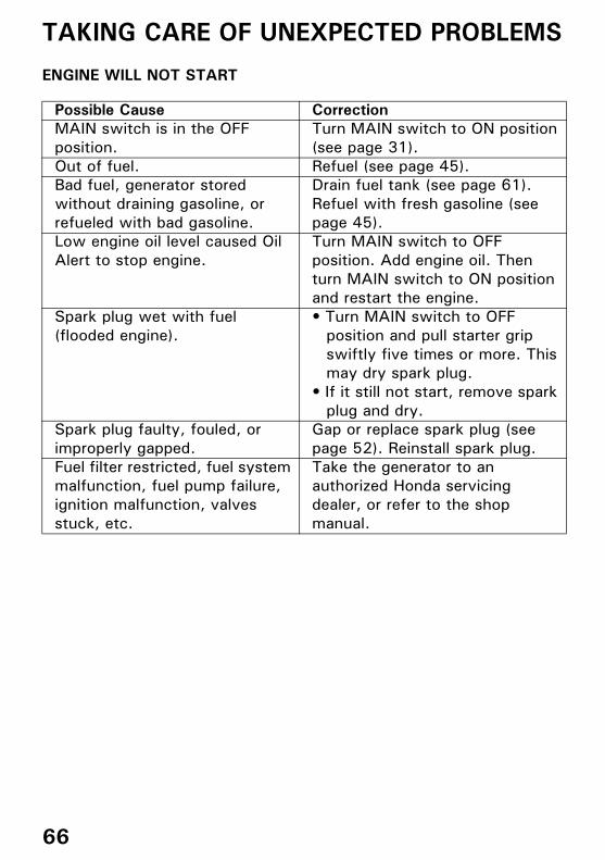
ENGINE WILL NOT START
Possible Cause CorrectionMAIN switch is in the OFF position.
Turn MAIN switch to ON position (see page 31).
Out of fuel. Refuel (see page 45).Bad fuel, generator stored without draining gasoline, or refueled with bad gasoline.
Drain fuel tank (see page 61).Refuel with fresh gasoline (see page 45).
Low engine oil level caused Oil Alert to stop engine.
Turn MAIN switch to OFF position. Add engine oil. Then turn MAIN switch to ON position and restart the engine.
Spark plug wet with fuel (flooded engine).
• Turn MAIN switch to OFF position and pull starter grip swiftly five times or more. This may dry spark plug.
• If it still not start, remove spark plug and dry.
Spark plug faulty, fouled, or improperly gapped.
Gap or replace spark plug (see page 52). Reinstall spark plug.
Fuel filter restricted, fuel system malfunction, fuel pump failure, ignition malfunction, valves stuck, etc.
Take the generator to an authorized Honda servicing dealer, or refer to the shop manual.
66

4MZ376000.book 67 ページ 2014年9月25日 木曜日 午前11時46分
TAKING CARE OF UNEXPECTED PROBLEMS
ENGINE LACKS POWER
NO POWER AT THE AC RECEPTACLES
Possible Cause CorrectionAir filter restricted. Clean or replace air filter (see
page 50).Bad fuel, generator stored without draining gasoline, or refueled with bad gasoline.
Drain fuel tank (see page 61).Refuel with fresh gasoline (see page 45).
Fuel filter restricted, fuel system malfunction, fuel pump failure, ignition malfunction, valves stuck, etc.
Take the generator to an authorized Honda servicing dealer, or refer to the shop manual.
Possible Cause CorrectionOUTPUT indicator is OFF, and OVERLOAD ALARM indicator is ON.
Check AC load. Stop and restart the engine.Check the cooling air inlet. Stop and restart the engine.
Faulty power tool or appliance. Replace or repair power tool or appliance.Stop and restart the engine.
Faulty generator. Take the generator to an authorized Honda servicing dealer, or refer to the shop manual.
67

4MZ376000.book 68 ページ 2014年9月25日 木曜日 午前11時46分
TECHNICAL INFORMATION
Serial Number Location
Record the frame serial number and date purchased in the spaces below. You will need this information when ordering parts and when making technical or warranty inquiries.
Frame serial number:
Date purchased:
FRAME SERIAL NUMBER
68
4MZ376000.book 69 ページ 2014年9月25日 木曜日 午前11時46分
TECHNICAL INFORMATION
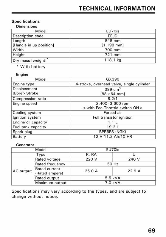
SpecificationsDimensions
* With battery
Engine
Generator
Specifications may vary according to the types, and are subject to change without notice.
Model EU70isDescription code EEJDLength[Handle in up position]
848 mm[1,198 mm]
Width 700 mmHeight 721 mmDry mass [weight]* 118.1 kg
Model GX390Engine type 4-stroke, overhead valve, single cylinderDisplacement[Bore×Stroke]
389 cm3
[88×64 mm]Compression ratio 8.2:1Engine speed 2,400–3,600 rpm
<with Eco-Throttle switch ON>Cooling system Forced airIgnition system Full transistor ignitionEngine oil capacity 1.1 LFuel tank capacity 19.2 LSpark plug BPR6ES (NGK)Battery 12 V 11.2 Ah/10 HR
Model EU70isType R, RA U
AC output
Rated voltage 220 V 240 VRated frequency 50 HzRated current(Rated ampere) 25.0 A 22.9 A
Rated output 5.5 kVAMaximum output 7.0 kVA
69

4MZ376000.book 70 ページ 2014年9月25日 木曜日 午前11時46分
ASSEMBLY
SAFETY
The Importance of Proper AssemblyProper assembly is essential to operator safety and the reliability of the machine. Any error or oversight made by the person assembling and servicing a unit can easily result in faulty operation, damage to the machine, or injury to the operator.
Some of the most important safety precautions are given below. However, we cannot warn you of every conceivable hazard that can arise in performing this assembly. Only you can decide whether or not you should perform a given task.
Improper assembly can cause an unsafe condition that can lead to serious injury or death.
Follow the procedures and precautions in the assembly instructions carefully.
Failure to properly follow instructions and precautions can cause you to be seriously hurt or killed.
Follow the procedures and precautions in this manual carefully.
70

4MZ376000.book 71 ページ 2014年9月25日 木曜日 午前11時46分
ASSEMBLY
Important Safety Precautions• Make sure you have a clear understanding of all basic shop safety
practices and that you are wearing appropriate clothing and safety equipment. When performing this assembly, be especially careful of the following:
Read the instructions before you begin, and be sure you have the tools and skills required to perform the tasks safely.
• Make sure the engine is off before you begin any assembly, maintenance, or repairs. This will help eliminate several potential hazards:
Carbon monoxide poisoning from engine exhaust. Operate outside away from open windows or doors.
Burns from hot parts. Let the engine and exhaust system cool before touching.
Injury from moving parts. Do not run the engine unless the instruction tells you to do so. Even then, keep your hands, fingers, and clothing away. Do not run the engine when any protective guard or shield is removed.
• To reduce the possibility of a fire or explosion, be careful when working around gasoline or batteries. Use only a non-flammable solvent, not gasoline, to clean parts. Keep all cigarettes, sparks, and flames away from all fuel-related parts.
71
4MZ376000.book 72 ページ 2014年9月25日 木曜日 午前11時46分
ASSEMBLY
ASSEMBLY
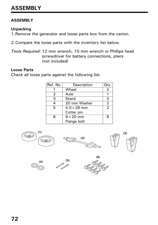
Unpacking1.Remove the generator and loose parts box from the carton.
2.Compare the loose parts with the inventory list below.
Tools Required: 12 mm wrench, 10 mm wrench or Phillips head screwdriver for battery connections, pliers (not included)
Loose PartsCheck all loose parts against the following list.
Ref. No. Description Qty.1 Wheel 22 Axle 13 Stand 24 20 mm Washer 25 4.0×28 mm
Cotter pin2
6 8×20 mm Flange bolt
8
(1)
(2)
(3)
(4) (5)(6)
72
4MZ376000.book 73 ページ 2014年9月25日 木曜日 午前11時46分
ASSEMBLY
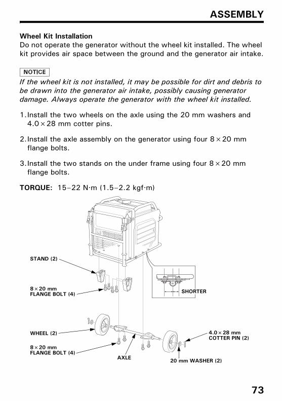
Wheel Kit InstallationDo not operate the generator without the wheel kit installed. The wheel kit provides air space between the ground and the generator air intake.
If the wheel kit is not installed, it may be possible for dirt and debris to be drawn into the generator air intake, possibly causing generator damage. Always operate the generator with the wheel kit installed.
1.Install the two wheels on the axle using the 20 mm washers and 4.0×28 mm cotter pins.
2.Install the axle assembly on the generator using four 8×20 mm flange bolts.
3.Install the two stands on the under frame using four 8×20 mm flange bolts.
TORQUE: 15–22 N·m (1.5–2.2 kgf·m)
STAND (2)
8×20 mm FLANGE BOLT (4)
4.0×28 mm COTTER PIN (2)
AXLE
WHEEL (2)
8×20 mm FLANGE BOLT (4)
20 mm WASHER (2)
SHORTER
73

4MZ376000.book 74 ページ 2014年9月25日 木曜日 午前11時46分
ASSEMBLY
Battery
Battery posts, terminals, and related accessories contain lead and lead compounds. Wash hands after handling.
The battery is disconnected and strapped into the battery tray for shipment.
1.Remove the battery maintenance cover (see page 56).2.Remove the battery strap from the bottom hook, and then remove
the battery.3.Only remove the battery cables from the twist clip.
Make sure that the 4-pin blue coupler harness is secured with the twist clip. Charge the battery properly. See page 58.Reinstall the battery.
4.Remove the protective cover from the battery positive (+) terminal, and connect the positive (+) cable to the battery positive (+) terminal. Make sure to cover the terminal with the battery boot.
5.Connect the negative (–) cable to the battery negative (–) terminal.6.Secure the battery by hooking the strap onto the bottom hook of the
generator.
7.Install the battery maintenance cover in the reverse order of removal (see page 56).Never operate the generator with the battery maintenance cover open, as poor engine and generator performance will result.
TWIST CLIP
BOTTOM HOOK 4-PIN BLUE COUPLER HARNESS
BATTERY CABLES
NEGATIVE (–) CABLE
BATTERY STRAP
BATTERYPOSITIVE (+) CABLE
BATTERY BOOT
74

4MZ376000.book 75 ページ 2014年9月25日 木曜日 午前11時46分
ASSEMBLY
Engine Oil
The generator is shipped WITHOUT OIL in the engine.
Place the generator on a level surface. Open the right maintenance cover by turning its latch counterclockwise.Remove the oil filler cap.Add enough of the recommended oil to bring the oil level to the upper limit of the oil filler neck.
Use a 4-stroke motor oil that meets the requirements for API service category SE or later (or equivalent).
SAE 10W-30 is recommended for general, all-temperature use. Other viscosities in the chart may be used when the temperature in your area is within the indicated range.
Reinstall the oil filler cap securely. Close the right maintenance cover by turning its latch clockwise.
Fuel
Refer to page 45.
AMBIENT TEMPERATURE
OIL FILLER CAP
OIL FILLER NECK
UPPER LIMIT
75

4MZ376000.book 76 ページ 2014年9月25日 木曜日 午前11時46分
ASSEMBLY
Battery Voltage
Check the battery voltage with the i-Monitor (see page 24).
The battery voltage should be 12.3 V or more.
If the battery voltage is low, charge the battery until the battery voltage is 12.3 V or more.
BEFORE OPERATION
Before using the generator, all generator operators must read the following chapters and sections:
• GENERATOR SAFETY (see page 6)
• CONTROLS & FEATURES (see page 14)
• BEFORE OPERATION (see page 27)
• OPERATION (see page 29)
• STARTING THE ENGINE (see page 30)
• STOPPING THE ENGINE (see page 33)
• MAINTENANCE SCHEDULE (see page 44)
76

4MZ376000.book 77 ページ 2014年9月25日 木曜日 午前11時46分
OPTIONAL PARTS
REMOTE CONTROL KIT (R, U type only)
Using the remote control in wet conditions, such as rain or snow, or near a pool or sprinkler system, or when your hands are wet, could result in malfunction. Keep the remote control dry.(degree of protection: IP3X)
1.Remove the battery maintenance cover (see page 56).
2.Remove the plug from the connector.• Do not discard the plug. The plug should be installed back into the
connector when the remote control kit is removed.
3.View the back of the battery maintenance cover and locate theknockout near the top center of the cover. Carefully remove theknockout.
PLUG
BATTERY MAINTENANCE COVERKNOCKOUT
77

4MZ376000.book 78 ページ 2014年9月25日 木曜日 午前11時46分
OPTIONAL PARTS
4.Fit the grommet into the battery maintenance cover knockout.5.Plug the remote control cable into the connector.6.Install the battery maintenance cover and tighten the cover screw.
7.To avoid accidentally unplugging the remote control cable, securethe cable to the generator frame with a cable tie as shown.
• Never operate the generator withthe battery maintenance coveropen, as poor engine and generatorperformance will result.
• Install the plug to the connectorwhen the remote control kit isremoved.
GROMMET
REMOTE CONTROL CABLE
BATTERY MAINTENANCE COVER REMOTE CONTROL BOX
REMOTE CONTROL CABLE
CABLE TIE
PLUG
78

4MZ376000.book 79 ページ 2014年9月25日 木曜日 午前11時46分
OPTIONAL PARTS
HANGER KIT
Protect the fuel tank and frame pipe with the protector films during installation of the hanger.
1.Slide one end of the hanger under the frame pipe on the left side ofthe generator.
2.Slide the other end of the hanger under the frame pipe on the rightside of the generator.
3.Slide the hanger along the frame pipes to align the center of thehanger with the recessed part on the rear side of the fuel tank.
4.Install the hanger brackets on both ends of the hanger and tightenthe 8×16 mm flange bolts securely.
TORQUE: 24–29 N·m (2.4–3.0 kgf·m)
PROTECTOR FILM (commercially available)
HANGER
8×16 mm FLANGE BOLT (4)
HANGER BRACKET (2)
HANGER
79

80
MEMO
4MZ376000.book 80 ページ 2014年9月25日 木曜日 午前11時46分

81
MEMO
4MZ376000.book 81 ページ 2014年9月25日 木曜日 午前11時46分

82
MEMO
4MZ376000.book 82 ページ 2014年9月25日 木曜日 午前11時46分