
Giải mã chập
54
Lời nói đầu Trong lĩnh vực truyền thông, các quá trình mã hóa và giải mã được sử dụng nhiều với các chức năng khác nhau nhằm đảm bảo tính bảo mật, độ tin cậy cao khi truyền tin. Do đó, việc xây dựng các phương pháp mã hóa, giải mã, việc chọn lựa các tham số cho bộ tạo mã (encoder) và các bộ giải mã (decoder) là rất quan trọng trong truyền tin an toàn. Cho đến nay, thông thường các phương pháp mã hóa và giải mã chỉ được phân tích trên cơ sở phương pháp xử lý tín hiệu truyền thống, biểu diễn theo thời gian, tần số hay không gian. Tuy vậy, dù được phân tích trên cơ sở nào, thì việc thiết lập các bộ tạo mã hay giải mã đều được thực hiện dựa vào các mô hình khối ở bước ban đầu. Hay nói cách khác, việc thiết lập các bộ tạo mã hay giải mã chính là việc xây dựng một mô hình hệ thống với đầu vào là tin tức, đầu ra là các từ mã và các biến trạng thái có trong hệ thống. Vì vậy, việc nhìn nhận mã hóa và giải mã trên quan điểm lý thuyết hệ thống là có cơ sở thực hiện. Đặc biệt, việc nghiên cứumã sửa sai trên quan điểm lý thuyết hệ thống có tầm quan trọng đối với việc tìm các mã có khả năng sửa sai tốt, cần ít bit dư thừa, hay tìm ra các mã mạnh kết hợp với khả năng quan sát, điều khiển đồng thời để tối ưu hóa quá trình mã hóa và giải mã. Page 1
-
Upload
pham-hoang-anh -
Category
Documents
-
view
472 -
download
8
Transcript of Giải mã chập

Lời nói đầu
Trong lĩnh vực truyền thông, các quá trình mã hóa và giải mã được sử dụng
nhiều với các chức năng khác nhau nhằm đảm bảo tính bảo mật, độ tin cậy cao khi
truyền tin. Do đó, việc xây dựng các phương pháp mã hóa, giải mã, việc chọn lựa
các tham số cho bộ tạo mã (encoder) và các bộ giải mã (decoder) là rất quan trọng
trong truyền tin an toàn. Cho đến nay, thông thường các phương pháp mã hóa và
giải mã chỉ được phân tích trên cơ sở phương pháp xử lý tín hiệu truyền thống,
biểu diễn theo thời gian, tần số hay không gian. Tuy vậy, dù được phân tích trên
cơ sở nào, thì việc thiết lập các bộ tạo mã hay giải mã đều được thực hiện dựa vào
các mô hình khối ở bước ban đầu. Hay nói cách khác, việc thiết lập các bộ tạo mã
hay giải mã chính là việc xây dựng một mô hình hệ thống với đầu vào là tin tức,
đầu ra là các từ mã và các biến trạng thái có trong hệ thống. Vì vậy, việc nhìn
nhận mã hóa và giải mã trên quan điểm lý thuyết hệ thống là có cơ sở thực hiện.
Đặc biệt, việc nghiên cứumã sửa sai trên quan điểm lý thuyết hệ thống có tầm
quan trọng đối với việc tìm các mã có khả năng sửa sai tốt, cần ít bit dư thừa, hay
tìm ra các mã mạnh kết hợp với khả năng quan sát, điều khiển đồng thời để tối ưu
hóa quá trình mã hóa và giải mã.
Trong khuôn khổ của môn học, mã chập được sử dụng để phân tích và làm
rõ thêm về việc biểu diễn mã trong không gian trạng thái. Ngoài ra, project còn
biểu diễn một bộ tạo mã và giải mã chập sử dụng phần mềm Matlab2010 nhằm có
cái nhìn rõ hơn về quá trình tạo mã và giải mã. Do hạn chế về thời gian tìm hiểu
nên để tài còn nhiều thiếu sót và kính mong cô chỉ bảo để đề tại được bổ sung
trong thời gian tới.
Page 1

Mục LụcChương 1.Lý thuyết về mã chập.......................................................................................................3
1.1. Bộ tạo mã chập.............................................................................................................3
1.2. Bộ giải mã chập............................................................................................................5
Chương 2: Mô phỏng bộ mã hóa và giải mã mã chập.....................................................................8
2.1. Mô hình của bộ mã hóa................................................................................................8
2.2. Kết quả mô phỏng......................................................................................................10
Kết luận.............................................................................................................................................12
Tài liệu tham khảo...........................................................................................................................13
Page 2

Chương 1.Lý thuyết về mã chập
1.1. Bộ tạo mã chập
Mã chập là một loại mã sửa sai được sử dụng trong mã hóa kênh với từ mã
được tạo ra nhờ việc cộng các bit thông tin và các bit có trong các thanh ghi dịch.
Để tạo ra mã chập, ta dùng bộ lập mã chập có nguyên tắc hoạt động dựa vào việc
“chập” dòng bit thông tin đầu vào với đáp ứng xung của bộ tạo mã. Do đó, một
dãy thông tin nhị phân u được chia thành kí tự dk=(dk(0),…..,dk
(k-1)). Các kí tự này
được ánh xạ thông qua bộ tạo mã gồm n bit. Hai tham số quan trọng của một từ
mã chập là tốc độ mã R = k/n và độ dài ràng buộc Kc = M+1 với M là số lượng
các thanh ghi dịch có trong bộ mã (độ dài ràng buộc là thời gian trải rộng của các
bit mà mỗi bít đầu vào ảnh hưởng lên). Hình 1 mô tả một bộ giải mã có tốc độ là
½, độ dài ràng buộc Kc = 3.
Hình 1. Sơ đồ khối và sơ đồ chuyển trạng thái của bộ tạo mã chập
Hình 1 cũng chỉ ra sơ đồ chuyển trạng thái tương ứng với các thanh ghi
dịch phía bên trái.Với các mã chập, việc mô tả bộ tạo mã bằng sơ đồ trạng thái sẽ
thuận lợi hơn. Nếu bộ lập mã có M thanh ghi dịch thì sẽ có 2M trạng thái S(m) với m
= 0,…,2M-1. Mỗi trạng thái được biểu diễn bởi một nút và sử chuyển đổi các trạng
thái được biểu diễn bằng các mũi tên. Trên các mũi tên mô tả bit đầu vào dk tương
ứng với các kí tự đầu ra xk được viết là dk/xk(0)x(1)
k.
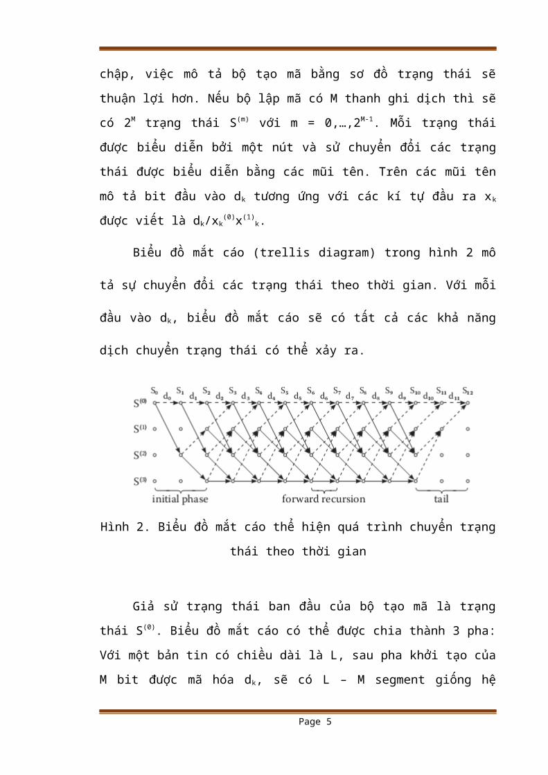
Biểu đồ mắt cáo (trellis diagram) trong hình 2 mô tả sự chuyển đổi các
trạng thái theo thời gian. Với mỗi đầu vào dk, biểu đồ mắt cáo sẽ có tất cả các khả
năng dịch chuyển trạng thái có thể xảy ra.
Page 3

Hình 2. Biểu đồ mắt cáo thể hiện quá trình chuyển trạng thái theo thời gian
Giả sử trạng thái ban đầu của bộ tạo mã là trạng thái S(0). Biểu đồ mắt cáo
có thể được chia thành 3 pha: Với một bản tin có chiều dài là L, sau pha khởi tạo
của M bit được mã hóa dk, sẽ có L – M segment giống hệ nhau. Sau khi bản tin có
chiều dài L được mã hóa hết, thì bộ tạo mã sẽ chuyển về trạng thái ban đầu bằng
cách thêm vào M kí tự. Do đó, chiều dài của từ mã được tăng lên LT = L + M. Kĩ
thuật thêm M kí tự này sẽ làm cải thiện khả năng bị lỗi tại điểm cuối của bản tin
được mã hóa.
Để hiểu rõ hơn về biểu đồ mắt cáo, ta xem xét hình 3. Hình 3 biểu diễn quá
trình tạo từ mã sử dụng biểu đồ mắt cáo với bản tin có độ dài 12 bit với nội dung
d= (0,1,0,1,1,0,0,1,1,1,0,0) và được 24 bit từ mã đầu ra xk
Hình 3. Ví dụ về sử dụng biểu đồ mắt cáo với đầu vào cho trước
1.2. Bộ giải mã chập
Page 4
Có nhiều phương pháp giải mã chập. Tuy nhiên, trong project này, chúng ta
sẽ đề cập đến thuật toán giải mã chập Viterbi. Lý thuyết chung của thuật toán này
là nhằm tìm ra đường ngắn nhất có trong biểu đồ mắt cáo , đường dẫn đến một
trạng thái S(k) phải là đường ngắn nhất có thể. Thuật toán này có thể được chia
thành hai bước: 1) tính toán giá nhánh (branch metric), giá đường (path metric) và
các bit quyết định. 2) traceback. Trong pha 1, sự sai khác giữa kí tự nhận yk và tất
cả các kí tự khác mà có khả năng nhận được được tính toán. Trong trường hợp
hard decision mà các kí tự chỉ là bit 0 hoặc 1, thì khoảng cách Hamming đươc sử
dụng để tính brach metric. Khoảng cách Hamming sẽ tính số bit sai khác trong kí
tự nhận được với số bit trong các kí tự có khả năng nhận được. Trong ví dụ ở phần
1, khoảng cách Hamming có thể là 0, 1, 2. Kết quả sẽ được lưu trong path
metric.Với mỗi bước k, khoảng cách Hamming cho mỗi trạng thái Sk được tính
toán và được cộng vào path metric của các trạng thái trước đó (k-1). Trong pha
thứ 2, thuật toán Viterbi sẽ dò ngược lại để xác định ra chuỗi kí tự gần nhất. Trạng
thái ban đầu trong pha dò ngược là trạng thái có path metric thấp nhất.
Để hiểu rõ hơn về thuật toán Viterbi. Chúng ta tiếp tục xét ví dụ trong phần
1 với từ mã cuối cùng nhận được yk bị sai khác so với từ mã sau bộ lập mã xk do
quá trình truyền dữ liệu. (Hình 4)
Hình 4. Ví dụ về thuật toán Virterbi
Sau quá trình truyền, yk bị sai khác so với xk tại những bit được tô màu đỏ
như trên hình 4. Bước đầu để giải mã kí tự thu là tạo ra bảng tra LUT mô tả sơ đồ
chuyển trạng thái. Bảng tra này được dùng để tính toán khoảng cách Hamming.
Page 5

Hình 5. Ma trận chuyển trạng thái
Như trong hình 4, S(0) sẽ chuyển đến 1 trong hai trạng thái là S(0) hoặc S(2)
sau khi nhận kí tự truyền đầu tiên. Do kí tự nhận được y1 = 00, nên kí tự này sẽ
được so sánh với hai kí tự tại hai trạng thái chuyển có thể có là S(0) và S(2). Nếu
S(0)-> S(0) thì khoảng cách Hamming là 0 và nếu chuyển tới S(2) thì khoảng cách
Hamming là 2. Giá trị này sẽ được lưu lại tại các nút tương ứng bên trong mắt
cáo.Giá trị này sẽ được tiếp tục tính toán tại các mắt khác nhau sau mỗi lẫn
chuyển trạng thái và được cộng dồn cả giá trị của trạng thái trước. Tại mỗi trạng
thái, sẽ có những giá trị path metric của các trạng thái trước đó được cộng dồn ,
những giá trị này được so sánh với nhau và giá trị nhỏ hơn sẽ được trọn là path
metric tại thời điểm đó. Nối tất cả các mắt cáo có path metric nhỏ nhất tại từng
thời điểm, ta sẽ có sơ đồ chuyển trạng thái tối ưu nhất. (đường màu đỏ trên Hình
6).
Hình 6. Kết quả thực hiện pha 1 của thuật toán Virterbi
Sau khi kết thúc pha 1, pha 2 sẽ thực hiện việc traceback dựa theo sơ đồ
chuyển trạng thái đã có của pha 1. Để khởi tạo traceback, trạng thái có path metric
Page 6

nhỏ nhất sẽ được đưa vào một thanh ghi dịch 2 bit, trong ví dụ này là 00. Giá trị
này chính là con trỏ để chọn các bit lựa chọn. Quá trình traceback được mô tả
trong hình 7.
Hình 7. Quá trình Traceback
Tổ hợp các bit được đẩy ra khỏi thanh ghi dịch 2 bit tạo thành bản tin ban
đầu (các bit màu vàng). Từ đó ta kết thúc quá trình giải mã mã chập.
Page 7

Chương 2:
Mô phỏng bộ mã hóa và giải mã mã chập
Trong chương này, một bộ tạo mã chập và giải mã được xây dựng và mô
phỏng sử dụng công cụ Simulink của Matlab 2010.Đầu tiên, mô hình của bộ mã
hóa được đưa ra.Sau đó; chúng ta thiết lập sơ đồ khối sử dụng các khối trong
Simulink để thực hiện việc mã hóa và giải mã mã chập.Cuối cùng, kết quả mô
phỏng sẽ được đưa ra để kiểm chứng.
2.1. Mô hình của bộ mã hóa
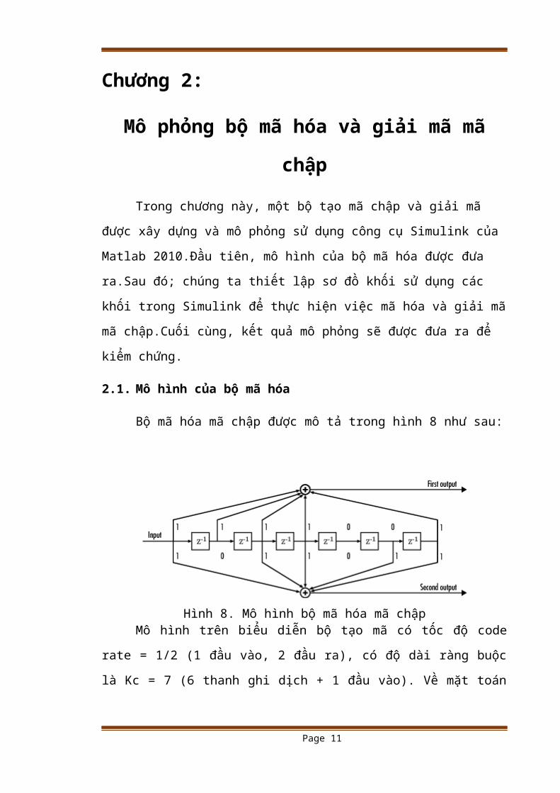
Bộ mã hóa mã chập được mô tả trong hình 8 như sau:
Hình 8. Mô hình bộ mã hóa mã chậpMô hình trên biểu diễn bộ tạo mã có tốc độ code rate = 1/2 (1 đầu vào, 2
đầu ra), có độ dài ràng buộc là Kc = 7 (6 thanh ghi dịch + 1 đầu vào). Về mặt toán
học, bộ mã chập trên được hình thành bởi ma trận đa thức có dạng:
Z4+Z3+Z2+Z+1Z6+Z5+Z 4+Z3+Z+1
Từsơđồ mô hình bộ mã hóa mã chập trên, chúng ta sử dụng công cụ
Simulink của Matlab nhằm xây dựng một bộ mã hóa và giải mã mã chập với mô
hình như trong hình 8 như sau:
Page 8

Hình 9.Mô hình mã hóa và giải mã mã chập
Trong mô hình trên, quá trình mã hóa và giải mã mã chập được mô tả
thông qua 4 khối.Đầu tiên, tín hiệu bản tin bất kì được tạo ra một cách ngẫu nhiên
thôn qua bộ tạo mã nhị phân Bernoulli. Sau đó, chuỗi bit nhị phân này được đưa
lần lượt vào bộ mã hóa mã chập rồi đưa quá kênh truyền nhị phân với một xác
suất lỗi kênh truyền nhất định và cuối cùng được giải mã qua bộ giải mã sử dụng
thuật toán Virterbi. Bộ mã hóa mã chập được xây dựng bằng việc khai báo các
thông số cho biểu đồ chuyển trạng thái (Trellis structure) được có trong bộ mã hóa
mã chập. Cách khai báo như sau:
Trellis = poly2trellis ([chiều dài ràng buộc], [ hệ số trong đa thức sinh dưới dạng
bát phân])
Hàm Poly2trellis có nhiệm vụ chuyển đổi dạng đa thức sang sơ đồ chuyển
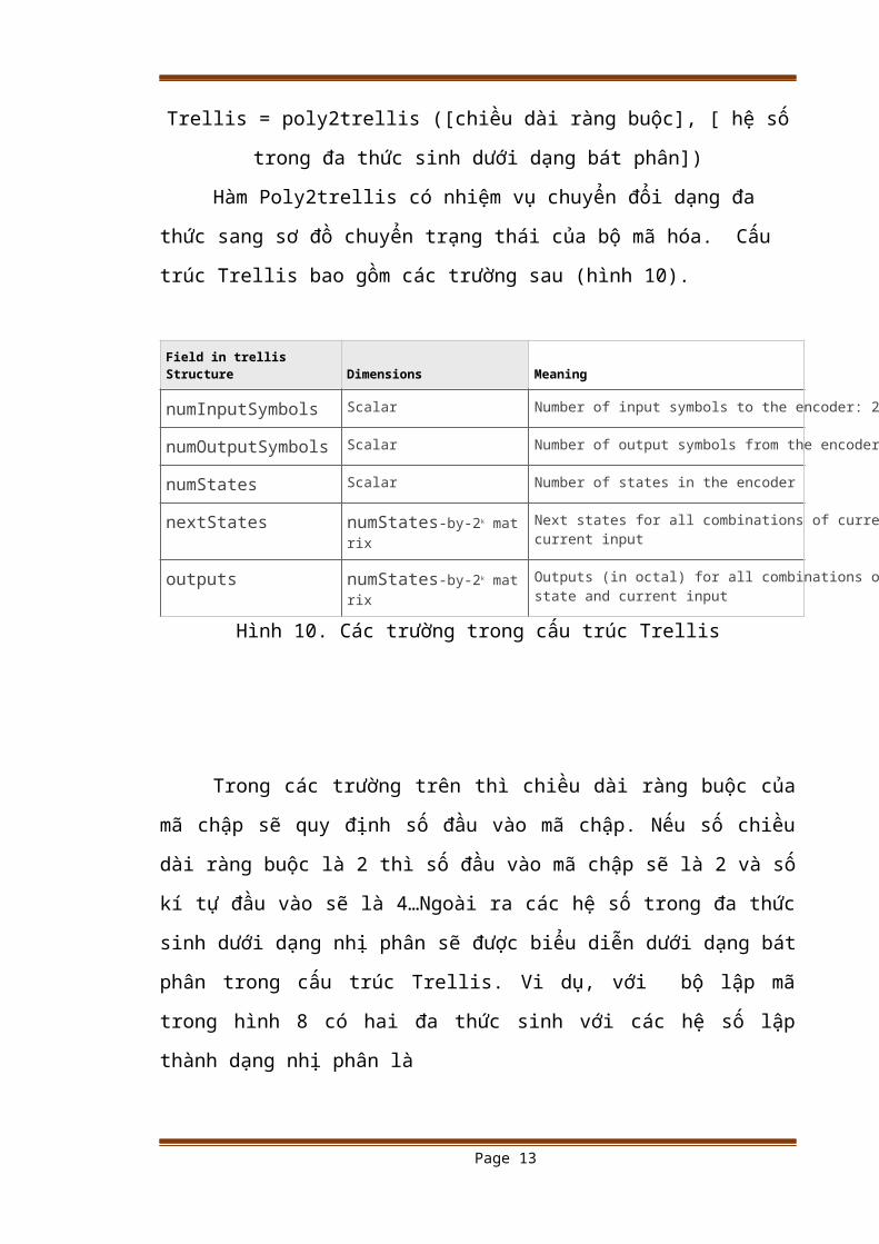
trạng thái của bộ mã hóa. Cấu trúc Trellis bao gồm các trường sau (hình 10).
Field in trellis Structure Dimensions Meaning
numInputSymbols Scalar Number of input symbols to the encoder: 2k
numOutputSymbols Scalar Number of output symbols from the encoder: 2
numStates Scalar Number of states in the encoder
nextStates numStates-by-2k matrix Next states for all combinations of current state and current input
outputs numStates-by-2k matrix Outputs (in octal) for all combinations of current state and current input
Hình 10. Các trường trong cấu trúc Trellis
Page 9

Trong các trường trên thì chiều dài ràng buộc của mã chập sẽ quy định số
đầu vào mã chập. Nếu số chiều dài ràng buộc là 2 thì số đầu vào mã chập sẽ là 2
và số kí tự đầu vào sẽ là 4…Ngoài ra các hệ số trong đa thức sinh dưới dạng nhị
phân sẽ được biểu diễn dưới dạng bát phân trong cấu trúc Trellis. Vi dụ, với bộ
lập mã trong hình 8 có hai đa thức sinh với các hệ số lập thành dạng nhị phân là
(1 1 1 1 0 0 1) ứng với đầu ra của bit thứ nhất và (1 0 1 1 0 1 1), trong khai báo
Trellis, dạng nhị phân này sẽ được đổi sang dạng bát phân là hai số 171 và 133.
Với bộ mã hóa như trên, cấu trúc trellis sẽ có 27 trạng thái trong bộ mã hóa.
Để hiểu rõ hơn về quá trình mã hóa và giải mã mã chập, kết quả mô phỏng
của bộ mã hóa này sẽ được đưa ra trong phần sau.
2.2. Kết quả mô phỏng
Với mô hình được cho trong hình 9, chúng ta thiết lập các thông số cho
từng khối như sau:
Khối tạo chuỗi bit nhị phân:
- Proballity of a zero: 0.5
- Initial seed: dùng hàm randseed
- Sample time: 0.5
Khối tạo mã chập: thiết lập Trellis poly2trellis ( 7, [171 133])
Khối kênh truyền đối xứng: xét xác suất lỗi: 0.02
Khối giải mã sử dụng thuật toán Virterbi: thiết lấp tương tự khối mã chập
Chọn thời gian mô phỏng từ 0 đến 100 s.
Sau khi đã thiết lập các khối, ta tiến hành mô phỏng và thu đươc kết quả
như trên hình 11
Page 10
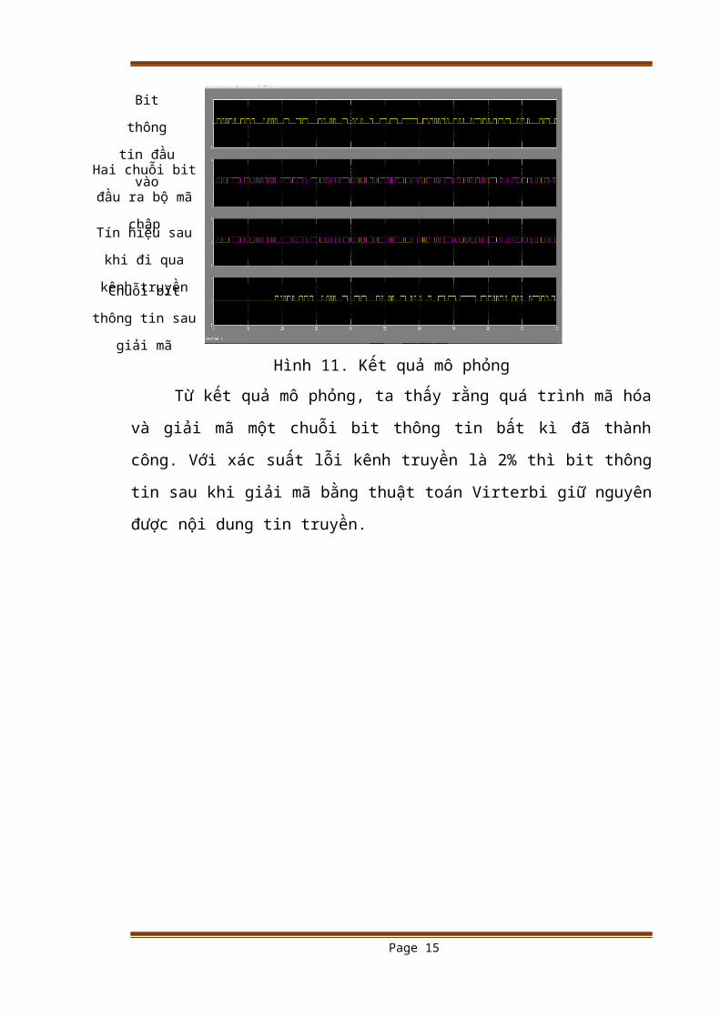
Hình 11. Kết quả mô phỏng
Từ kết quả mô phỏng, ta thấy rằng quá trình mã hóa và giải mã một chuỗi
bit thông tin bất kì đã thành công. Với xác suất lỗi kênh truyền là 2% thì bit thông
tin sau khi giải mã bằng thuật toán Virterbi giữ nguyên được nội dung tin truyền.
Page 11
Hai chuỗi bit đầu ra
bộ mã chập
Bit thông tin
đầu vào
Chuỗi bit thông tin
sau giải mã
Tín hiệu sau khi đi
qua kênh truyền

Kết luận
Như vậy, quá trình mô phỏng việc mã hóa và giải mã mã chập đã được
thực hiện.Việc thiết lập mã và giải mã đều dựa vào biểu đồ mắt cáo và thuật toán
giải mã Virterbi.Sự tiện lợi của công cụ Simulink trong phần mềm Matlab cho
phép chúng ta có thể xây dựng được bất kì bộ tạo mã chập chỉ bằng cách thay đổi
các tham số trong sơ đồ khối của bộ tạo mã.
Tuy nhiên, project còn nhiều thiếu sót. Đó là chưa nêu ra được vai trò làm
giảm thiểu lỗi kênh truyền của mã chập bằng cách thiết lập mối quan hệ đồ thị
giữa tỉ số tín hiệu trên nhiễu SNR và tỉ lệ lỗi bit BER. Ngoài ra, việc xây dựng bộ
tạo mã chập theo quan điểm lý thuyết hệ thống chưa được thực hiện. Đây là những
hướng cần khắc phục trong thời gian tới của project.
Page 12
Tài liệu tham khảo
[1] Eric V. York (1997), Algebraic Description and Construction of Error Correcting
Codes: A Linear Systems point of view, Dissertation for the degree of Philosophy
Doctor of the University of Notre Dame, Notre Dame Indiana, USA.
[2] Brian M. Allen, (1999). Linear systems analysis and decoding of convolutional
codes.
[3] www.mathwork.com
Page 13

PHỤ LỤC CODE/* This code was developed as part of graduate coursework at Embry-
Riddle Aeronautical University
* under the guidance of Dr. Pat Anderson and Dr. Hever Moncayo.
*
* Author: Robert F. Hartley
* Assistant Developers: Francois Hugon, Brian DeRosa, and Christopher
Carvalho
* Support: [email protected]
*
* Oct. 25, 2012
* Version 1.0
*
*/
/*
* File: Arduino_IMU_sfcn.c
*
*
*
* --- THIS FILE GENERATED BY S-FUNCTION BUILDER: 3.0 ---
*
* This file is an S-function produced by the S-Function
* Builder which only recognizes certain fields. Changes made
* outside these fields will be lost the next time the block is
* used to load, edit, and resave this file. This file will be overwritten
* by the S-function Builder block. If you want to edit this file by hand,
* you must change it only in the area defined as:
*
* %%%-SFUNWIZ_defines_Changes_BEGIN
* #define NAME 'replacement text'
Page 14
* %%% SFUNWIZ_defines_Changes_END
*
* DO NOT change NAME--Change the 'replacement text' only.
*
* For better compatibility with the Simulink Coder, the
* "wrapper" S-function technique is used. This is discussed
* in the Simulink Coder's Manual in the Chapter titled,
* "Wrapper S-functions".
*
* -------------------------------------------------------------------------
* | See matlabroot/simulink/src/sfuntmpl_doc.c for a more detailed
template |
* -------------------------------------------------------------------------
* Created: Thu Aug 9 02:31:58 2012
*
*
*/
#define S_FUNCTION_LEVEL 2
#define S_FUNCTION_NAME Arduino_IMU_sfcn
/
*<<<<<<<<<<<<<<<<<<<<<<<<<<<<<<<<<<<<<<<<<<<<<<<<<<<<
<<<<<<<<<<<<<*/
/* %%%-SFUNWIZ_defines_Changes_BEGIN --- EDIT HERE TO _END
*/
#define NUM_INPUTS 7
/* Input Port 0 */
#define IN_PORT_0_NAME p_degs
#define INPUT_0_WIDTH 1
#define INPUT_DIMS_0_COL 1
#define INPUT_0_DTYPE real_T
Page 15

#define INPUT_0_COMPLEX COMPLEX_NO
#define IN_0_FRAME_BASED FRAME_NO
#define IN_0_BUS_BASED 0
#define IN_0_BUS_NAME
#define IN_0_DIMS 1-D
#define INPUT_0_FEEDTHROUGH 1
#define IN_0_ISSIGNED 1
#define IN_0_WORDLENGTH 8
#define IN_0_FIXPOINTSCALING 1
#define IN_0_FRACTIONLENGTH 3
#define IN_0_BIAS 0
#define IN_0_SLOPE 0.125
/* Input Port 1 */
#define IN_PORT_1_NAME q_degs
#define INPUT_1_WIDTH 1
#define INPUT_DIMS_1_COL 1
#define INPUT_1_DTYPE real_T
#define INPUT_1_COMPLEX COMPLEX_NO
#define IN_1_FRAME_BASED FRAME_NO
#define IN_1_BUS_BASED 0
#define IN_1_BUS_NAME
#define IN_1_DIMS 1-D
#define INPUT_1_FEEDTHROUGH 1
#define IN_1_ISSIGNED 1
#define IN_1_WORDLENGTH 8
#define IN_1_FIXPOINTSCALING 1
#define IN_1_FRACTIONLENGTH 3
#define IN_1_BIAS 0
#define IN_1_SLOPE 0.125
/* Input Port 2 */
#define IN_PORT_2_NAME r_degs
Page 16

#define INPUT_2_WIDTH 1
#define INPUT_DIMS_2_COL 1
#define INPUT_2_DTYPE real_T
#define INPUT_2_COMPLEX COMPLEX_NO
#define IN_2_FRAME_BASED FRAME_NO
#define IN_2_BUS_BASED 0
#define IN_2_BUS_NAME
#define IN_2_DIMS 1-D
#define INPUT_2_FEEDTHROUGH 1
#define IN_2_ISSIGNED 1
#define IN_2_WORDLENGTH 8
#define IN_2_FIXPOINTSCALING 1
#define IN_2_FRACTIONLENGTH 3
#define IN_2_BIAS 0
#define IN_2_SLOPE 0.125
/* Input Port 3 */
#define IN_PORT_3_NAME nx_g
#define INPUT_3_WIDTH 1
#define INPUT_DIMS_3_COL 1
#define INPUT_3_DTYPE real_T
#define INPUT_3_COMPLEX COMPLEX_NO
#define IN_3_FRAME_BASED FRAME_NO
#define IN_3_BUS_BASED 0
#define IN_3_BUS_NAME
#define IN_3_DIMS 1-D
#define INPUT_3_FEEDTHROUGH 1
#define IN_3_ISSIGNED 1
#define IN_3_WORDLENGTH 8
#define IN_3_FIXPOINTSCALING 1
#define IN_3_FRACTIONLENGTH 3
#define IN_3_BIAS 0
Page 17

#define IN_3_SLOPE 0.125
/* Input Port 4 */
#define IN_PORT_4_NAME ny_g
#define INPUT_4_WIDTH 1
#define INPUT_DIMS_4_COL 1
#define INPUT_4_DTYPE real_T
#define INPUT_4_COMPLEX COMPLEX_NO
#define IN_4_FRAME_BASED FRAME_NO
#define IN_4_BUS_BASED 0
#define IN_4_BUS_NAME
#define IN_4_DIMS 1-D
#define INPUT_4_FEEDTHROUGH 1
#define IN_4_ISSIGNED 1
#define IN_4_WORDLENGTH 8
#define IN_4_FIXPOINTSCALING 1
#define IN_4_FRACTIONLENGTH 3
#define IN_4_BIAS 0
#define IN_4_SLOPE 0.125
/* Input Port 5 */
#define IN_PORT_5_NAME nz_g
#define INPUT_5_WIDTH 1
#define INPUT_DIMS_5_COL 1
#define INPUT_5_DTYPE real_T
#define INPUT_5_COMPLEX COMPLEX_NO
#define IN_5_FRAME_BASED FRAME_NO
#define IN_5_BUS_BASED 0
#define IN_5_BUS_NAME
#define IN_5_DIMS 1-D
#define INPUT_5_FEEDTHROUGH 1
#define IN_5_ISSIGNED 1
#define IN_5_WORDLENGTH 8
Page 18

#define IN_5_FIXPOINTSCALING 1
#define IN_5_FRACTIONLENGTH 3
#define IN_5_BIAS 0
#define IN_5_SLOPE 0.125
/* Input Port 6 */
#define IN_PORT_6_NAME temp_degC
#define INPUT_6_WIDTH 1
#define INPUT_DIMS_6_COL 1
#define INPUT_6_DTYPE real_T
#define INPUT_6_COMPLEX COMPLEX_NO
#define IN_6_FRAME_BASED FRAME_NO
#define IN_6_BUS_BASED 0
#define IN_6_BUS_NAME
#define IN_6_DIMS 1-D
#define INPUT_6_FEEDTHROUGH 1
#define IN_6_ISSIGNED 1
#define IN_6_WORDLENGTH 8
#define IN_6_FIXPOINTSCALING 1
#define IN_6_FRACTIONLENGTH 3
#define IN_6_BIAS 0
#define IN_6_SLOPE 0.125
#define NUM_OUTPUTS 7
/* Output Port 0 */
#define OUT_PORT_0_NAME p_degs
#define OUTPUT_0_WIDTH 1
#define OUTPUT_DIMS_0_COL 1
#define OUTPUT_0_DTYPE real_T
#define OUTPUT_0_COMPLEX COMPLEX_NO
#define OUT_0_FRAME_BASED FRAME_NO
#define OUT_0_BUS_BASED 0
Page 19

#define OUT_0_BUS_NAME
#define OUT_0_DIMS 1-D
#define OUT_0_ISSIGNED 1
#define OUT_0_WORDLENGTH 8
#define OUT_0_FIXPOINTSCALING 1
#define OUT_0_FRACTIONLENGTH 3
#define OUT_0_BIAS 0
#define OUT_0_SLOPE 0.125
/* Output Port 1 */
#define OUT_PORT_1_NAME q_degs
#define OUTPUT_1_WIDTH 1
#define OUTPUT_DIMS_1_COL 1
#define OUTPUT_1_DTYPE real_T
#define OUTPUT_1_COMPLEX COMPLEX_NO
#define OUT_1_FRAME_BASED FRAME_NO
#define OUT_1_BUS_BASED 0
#define OUT_1_BUS_NAME
#define OUT_1_DIMS 1-D
#define OUT_1_ISSIGNED 1
#define OUT_1_WORDLENGTH 8
#define OUT_1_FIXPOINTSCALING 1
#define OUT_1_FRACTIONLENGTH 3
#define OUT_1_BIAS 0
#define OUT_1_SLOPE 0.125
/* Output Port 2 */
#define OUT_PORT_2_NAME r_degs
#define OUTPUT_2_WIDTH 1
#define OUTPUT_DIMS_2_COL 1
#define OUTPUT_2_DTYPE real_T
#define OUTPUT_2_COMPLEX COMPLEX_NO
#define OUT_2_FRAME_BASED FRAME_NO
Page 20
#define OUT_2_BUS_BASED 0
#define OUT_2_BUS_NAME
#define OUT_2_DIMS 1-D
#define OUT_2_ISSIGNED 1
#define OUT_2_WORDLENGTH 8
#define OUT_2_FIXPOINTSCALING 1
#define OUT_2_FRACTIONLENGTH 3
#define OUT_2_BIAS 0
#define OUT_2_SLOPE 0.125
/* Output Port 3 */
#define OUT_PORT_3_NAME nx_g
#define OUTPUT_3_WIDTH 1
#define OUTPUT_DIMS_3_COL 1
#define OUTPUT_3_DTYPE real_T
#define OUTPUT_3_COMPLEX COMPLEX_NO
#define OUT_3_FRAME_BASED FRAME_NO
#define OUT_3_BUS_BASED 0
#define OUT_3_BUS_NAME
#define OUT_3_DIMS 1-D
#define OUT_3_ISSIGNED 1
#define OUT_3_WORDLENGTH 8
#define OUT_3_FIXPOINTSCALING 1
#define OUT_3_FRACTIONLENGTH 3
#define OUT_3_BIAS 0
#define OUT_3_SLOPE 0.125
/* Output Port 4 */
#define OUT_PORT_4_NAME ny_g
#define OUTPUT_4_WIDTH 1
#define OUTPUT_DIMS_4_COL 1
#define OUTPUT_4_DTYPE real_T
#define OUTPUT_4_COMPLEX COMPLEX_NO
Page 21

#define OUT_4_FRAME_BASED FRAME_NO
#define OUT_4_BUS_BASED 0
#define OUT_4_BUS_NAME
#define OUT_4_DIMS 1-D
#define OUT_4_ISSIGNED 1
#define OUT_4_WORDLENGTH 8
#define OUT_4_FIXPOINTSCALING 1
#define OUT_4_FRACTIONLENGTH 3
#define OUT_4_BIAS 0
#define OUT_4_SLOPE 0.125
/* Output Port 5 */
#define OUT_PORT_5_NAME nz_g
#define OUTPUT_5_WIDTH 1
#define OUTPUT_DIMS_5_COL 1
#define OUTPUT_5_DTYPE real_T
#define OUTPUT_5_COMPLEX COMPLEX_NO
#define OUT_5_FRAME_BASED FRAME_NO
#define OUT_5_BUS_BASED 0
#define OUT_5_BUS_NAME
#define OUT_5_DIMS 1-D
#define OUT_5_ISSIGNED 1
#define OUT_5_WORDLENGTH 8
#define OUT_5_FIXPOINTSCALING 1
#define OUT_5_FRACTIONLENGTH 3
#define OUT_5_BIAS 0
#define OUT_5_SLOPE 0.125
/* Output Port 6 */
#define OUT_PORT_6_NAME temp_degC
#define OUTPUT_6_WIDTH 1
#define OUTPUT_DIMS_6_COL 1
#define OUTPUT_6_DTYPE real_T
Page 22
#define OUTPUT_6_COMPLEX COMPLEX_NO
#define OUT_6_FRAME_BASED FRAME_NO
#define OUT_6_BUS_BASED 0
#define OUT_6_BUS_NAME
#define OUT_6_DIMS 1-D
#define OUT_6_ISSIGNED 1
#define OUT_6_WORDLENGTH 8
#define OUT_6_FIXPOINTSCALING 1
#define OUT_6_FRACTIONLENGTH 3
#define OUT_6_BIAS 0
#define OUT_6_SLOPE 0.125
#define NPARAMS 4
/* Parameter 1 */
#define PARAMETER_0_NAME lpf_filt_freq_hz
#define PARAMETER_0_DTYPE uint32_T
#define PARAMETER_0_COMPLEX COMPLEX_NO
/* Parameter 2 */
#define PARAMETER_1_NAME gyro_scale
#define PARAMETER_1_DTYPE uint32_T
#define PARAMETER_1_COMPLEX COMPLEX_NO
/* Parameter 3 */
#define PARAMETER_2_NAME accel_scale
#define PARAMETER_2_DTYPE uint32_T
#define PARAMETER_2_COMPLEX COMPLEX_NO
/* Parameter 4 */
#define PARAMETER_3_NAME SampleTime
#define PARAMETER_3_DTYPE real_T
#define PARAMETER_3_COMPLEX COMPLEX_NO
#define SAMPLE_TIME_0 SampleTime
Page 23
#define NUM_DISC_STATES 0
#define DISC_STATES_IC [0]
#define NUM_CONT_STATES 0
#define CONT_STATES_IC [0]
#define SFUNWIZ_GENERATE_TLC 0
#define SOURCEFILES "__SFB__"
#define PANELINDEX 6
#define USE_SIMSTRUCT 0
#define SHOW_COMPILE_STEPS 0
#define CREATE_DEBUG_MEXFILE 0
#define SAVE_CODE_ONLY 1
#define SFUNWIZ_REVISION 3.0
/* %%%-SFUNWIZ_defines_Changes_END --- EDIT HERE TO _BEGIN
*/
/
*<<<<<<<<<<<<<<<<<<<<<<<<<<<<<<<<<<<<<<<<<<<<<<<<<<<<
<<<<<<<<<<<<<*/
#include "simstruc.h"
#define PARAM_DEF0(S) ssGetSFcnParam(S, 0)
#define PARAM_DEF1(S) ssGetSFcnParam(S, 1)
#define PARAM_DEF2(S) ssGetSFcnParam(S, 2)
#define PARAM_DEF3(S) ssGetSFcnParam(S, 3)
#define IS_PARAM_DOUBLE(pVal) (mxIsNumeric(pVal) && !
mxIsLogical(pVal) &&\
!mxIsEmpty(pVal) && !mxIsSparse(pVal) && !mxIsComplex(pVal) &&
mxIsDouble(pVal))
/*====================*
Page 24
* S-function methods *
*====================*/
#define MDL_CHECK_PARAMETERS
#if defined(MDL_CHECK_PARAMETERS) &&
defined(MATLAB_MEX_FILE)
/* Function: mdlCheckParameters
=============================================
* Abstract:
* Validate our parameters to verify they are okay.
*/
static void mdlCheckParameters(SimStruct *S)
{
int paramIndex = 0;
bool validParam = false;
/* All parameters must match the S-function Builder Dialog */
/* {
const mxArray *pVal0 = ssGetSFcnParam(S,0);
if (!IS_PARAM_DOUBLE(pVal0)) {
validParam = true;
paramIndex = 0;
goto EXIT_POINT;
}
}
{
const mxArray *pVal1 = ssGetSFcnParam(S,1);
if (!IS_PARAM_DOUBLE(pVal1)) {
validParam = true;
paramIndex = 1;
Page 25

goto EXIT_POINT;
}
}
{
const mxArray *pVal2 = ssGetSFcnParam(S,2);
if (!IS_PARAM_DOUBLE(pVal2)) {
validParam = true;
paramIndex = 2;
goto EXIT_POINT;
}
}
*/
{
const mxArray *pVal3 = ssGetSFcnParam(S,3);
if (!mxIsDouble(pVal3)) {
ssSetErrorStatus(S,"Sample time parameter SampleTime must be
of type double");
return;
}
}
{
const mxArray *pVal3 = ssGetSFcnParam(S,3);
if (!IS_PARAM_DOUBLE(pVal3)) {
validParam = true;
paramIndex = 3;
goto EXIT_POINT;
}
}
Page 26
EXIT_POINT:
if (validParam) {
char parameterErrorMsg[1024];
sprintf(parameterErrorMsg, "The data type and or complexity of
parameter %d does not match the "
"information specified in the S-function Builder dialog. "
"For non-double parameters you will need to cast them using
int8, int16, "
"int32, uint8, uint16, uint32 or boolean.", paramIndex + 1);
ssSetErrorStatus(S,parameterErrorMsg);
}
return;
}
#endif /* MDL_CHECK_PARAMETERS */
/* Function: mdlInitializeSizes
===============================================
* Abstract:
* Setup sizes of the various vectors.
*/
static void mdlInitializeSizes(SimStruct *S)
{
DECL_AND_INIT_DIMSINFO(outputDimsInfo);
ssSetNumSFcnParams(S, NPARAMS); /* Number of expected
parameters */
#if defined(MATLAB_MEX_FILE)
if (ssGetNumSFcnParams(S) == ssGetSFcnParamsCount(S)) {
mdlCheckParameters(S);
if (ssGetErrorStatus(S) != NULL) {
return;
}
Page 27
} else {
return; /* Parameter mismatch will be reported by Simulink */
}
#endif
ssSetNumContStates(S, NUM_CONT_STATES);
ssSetNumDiscStates(S, NUM_DISC_STATES);
if (!ssSetNumInputPorts(S, NUM_INPUTS)) return;
/* Input Port 0 */
ssSetInputPortWidth(S, 0, INPUT_0_WIDTH);
ssSetInputPortDataType(S, 0, SS_DOUBLE);
ssSetInputPortComplexSignal(S, 0, INPUT_0_COMPLEX);
ssSetInputPortDirectFeedThrough(S, 0, INPUT_0_FEEDTHROUGH);
ssSetInputPortRequiredContiguous(S, 0, 1); /*direct input signal
access*/
/* Input Port 1 */
ssSetInputPortWidth(S, 1, INPUT_1_WIDTH);
ssSetInputPortDataType(S, 1, SS_DOUBLE);
ssSetInputPortComplexSignal(S, 1, INPUT_1_COMPLEX);
ssSetInputPortDirectFeedThrough(S, 1, INPUT_1_FEEDTHROUGH);
ssSetInputPortRequiredContiguous(S, 1, 1); /*direct input signal
access*/
/* Input Port 2 */
ssSetInputPortWidth(S, 2, INPUT_2_WIDTH);
ssSetInputPortDataType(S, 2, SS_DOUBLE);
ssSetInputPortComplexSignal(S, 2, INPUT_2_COMPLEX);
ssSetInputPortDirectFeedThrough(S, 2, INPUT_2_FEEDTHROUGH);
Page 28
ssSetInputPortRequiredContiguous(S, 2, 1); /*direct input signal
access*/
/* Input Port 3 */
ssSetInputPortWidth(S, 3, INPUT_3_WIDTH);
ssSetInputPortDataType(S, 3, SS_DOUBLE);
ssSetInputPortComplexSignal(S, 3, INPUT_3_COMPLEX);
ssSetInputPortDirectFeedThrough(S, 3, INPUT_3_FEEDTHROUGH);
ssSetInputPortRequiredContiguous(S, 3, 1); /*direct input signal
access*/
/* Input Port 4 */
ssSetInputPortWidth(S, 4, INPUT_4_WIDTH);
ssSetInputPortDataType(S, 4, SS_DOUBLE);
ssSetInputPortComplexSignal(S, 4, INPUT_4_COMPLEX);
ssSetInputPortDirectFeedThrough(S, 4, INPUT_4_FEEDTHROUGH);
ssSetInputPortRequiredContiguous(S, 4, 1); /*direct input signal
access*/
/* Input Port 5 */
ssSetInputPortWidth(S, 5, INPUT_5_WIDTH);
ssSetInputPortDataType(S, 5, SS_DOUBLE);
ssSetInputPortComplexSignal(S, 5, INPUT_5_COMPLEX);
ssSetInputPortDirectFeedThrough(S, 5, INPUT_5_FEEDTHROUGH);
ssSetInputPortRequiredContiguous(S, 5, 1); /*direct input signal
access*/
/* Input Port 6 */
ssSetInputPortWidth(S, 6, INPUT_6_WIDTH);
ssSetInputPortDataType(S, 6, SS_DOUBLE);
ssSetInputPortComplexSignal(S, 6, INPUT_6_COMPLEX);
Page 29
ssSetInputPortDirectFeedThrough(S, 6, INPUT_6_FEEDTHROUGH);
ssSetInputPortRequiredContiguous(S, 6, 1); /*direct input signal
access*/
if (!ssSetNumOutputPorts(S, NUM_OUTPUTS)) return;
/* Output Port 0 */
ssSetOutputPortWidth(S, 0, OUTPUT_0_WIDTH);
ssSetOutputPortDataType(S, 0, SS_DOUBLE);
ssSetOutputPortComplexSignal(S, 0, OUTPUT_0_COMPLEX);
/* Output Port 1 */
ssSetOutputPortWidth(S, 1, OUTPUT_1_WIDTH);
ssSetOutputPortDataType(S, 1, SS_DOUBLE);
ssSetOutputPortComplexSignal(S, 1, OUTPUT_1_COMPLEX);
/* Output Port 2 */
ssSetOutputPortWidth(S, 2, OUTPUT_2_WIDTH);
ssSetOutputPortDataType(S, 2, SS_DOUBLE);
ssSetOutputPortComplexSignal(S, 2, OUTPUT_2_COMPLEX);
/* Output Port 3 */
ssSetOutputPortWidth(S, 3, OUTPUT_3_WIDTH);
ssSetOutputPortDataType(S, 3, SS_DOUBLE);
ssSetOutputPortComplexSignal(S, 3, OUTPUT_3_COMPLEX);
/* Output Port 4 */
ssSetOutputPortWidth(S, 4, OUTPUT_4_WIDTH);
ssSetOutputPortDataType(S, 4, SS_DOUBLE);
ssSetOutputPortComplexSignal(S, 4, OUTPUT_4_COMPLEX);
/* Output Port 5 */
ssSetOutputPortWidth(S, 5, OUTPUT_5_WIDTH);
ssSetOutputPortDataType(S, 5, SS_DOUBLE);
ssSetOutputPortComplexSignal(S, 5, OUTPUT_5_COMPLEX);
/* Output Port 6 */
ssSetOutputPortWidth(S, 6, OUTPUT_6_WIDTH);
Page 30
ssSetOutputPortDataType(S, 6, SS_DOUBLE);
ssSetOutputPortComplexSignal(S, 6, OUTPUT_6_COMPLEX);
ssSetNumSampleTimes(S, 1);
ssSetNumRWork(S, 0);
ssSetNumIWork(S, 0);
ssSetNumPWork(S, 0);
ssSetNumModes(S, 0);
ssSetNumNonsampledZCs(S, 0);
/* Take care when specifying exception free code - see sfuntmpl_doc.c
*/
ssSetOptions(S, (SS_OPTION_EXCEPTION_FREE_CODE |
SS_OPTION_WORKS_WITH_CODE_REUSE));
}
/* Function: mdlInitializeSampleTimes
=========================================
* Abstract:
* Specifiy the sample time.
*/
static void mdlInitializeSampleTimes(SimStruct *S)
{
ssSetSampleTime(S, 0, *mxGetPr(ssGetSFcnParam(S, 3)));
ssSetOffsetTime(S, 0, 0.0);
}
#define MDL_SET_OUTPUT_PORT_DATA_TYPE
static void mdlSetOutputPortDataType(SimStruct *S, int port, DTypeId
dType)
{
Page 31
ssSetOutputPortDataType(S, 0, dType);
}
#define MDL_SET_INPUT_PORT_DATA_TYPE
static void mdlSetInputPortDataType(SimStruct *S, int port, DTypeId
dType)
{
ssSetInputPortDataType(S, 0, dType);
}
#define MDL_SET_DEFAULT_PORT_DATA_TYPES
static void mdlSetDefaultPortDataTypes(SimStruct *S)
{
ssSetOutputPortDataType(S, 0, SS_DOUBLE);
ssSetInputPortDataType(S, 0, SS_DOUBLE);
}
/* Function: mdlOutputs
=====================================================
==
*
*/
static void mdlOutputs(SimStruct *S, int_T tid)
{
real_T *p_degs = (real_T *)ssGetOutputPortRealSignal(S,0);
real_T *q_degs = (real_T *)ssGetOutputPortRealSignal(S,1);
real_T *r_degs = (real_T *)ssGetOutputPortRealSignal(S,2);
real_T *nx_g = (real_T *)ssGetOutputPortRealSignal(S,3);
real_T *ny_g = (real_T *)ssGetOutputPortRealSignal(S,4);
real_T *nz_g = (real_T *)ssGetOutputPortRealSignal(S,5);
real_T *temp_degC = (real_T *)ssGetOutputPortRealSignal(S,6);
Page 32

const int_T p_width0 =
mxGetNumberOfElements(PARAM_DEF0(S));
const int_T p_width1 =
mxGetNumberOfElements(PARAM_DEF1(S));
const int_T p_width2 =
mxGetNumberOfElements(PARAM_DEF2(S));
const int_T p_width3 =
mxGetNumberOfElements(PARAM_DEF3(S));
const uint32_T *lpf_filt_freq_hz = (const uint32_T
*)mxGetData(PARAM_DEF0(S));
const uint32_T *gyro_scale = (const uint32_T
*)mxGetData(PARAM_DEF1(S));
const uint32_T *accel_scale = (const uint32_T
*)mxGetData(PARAM_DEF2(S));
const real_T *SampleTime = (const real_T
*)mxGetData(PARAM_DEF3(S));
const real_T *p_degs_in = (real_T *)ssGetInputPortRealSignal(S,0);
const real_T *q_degs_in = (real_T *)ssGetInputPortRealSignal(S,1);
const real_T *r_degs_in = (real_T *)ssGetInputPortRealSignal(S,2);
const real_T *nx_g_in = (real_T *)ssGetInputPortRealSignal(S,3);
const real_T *ny_g_in = (real_T *)ssGetInputPortRealSignal(S,4);
const real_T *nz_g_in = (real_T *)ssGetInputPortRealSignal(S,5);
const real_T *temp_degC_in = (real_T
*)ssGetInputPortRealSignal(S,6);
p_degs[0] = p_degs_in[0];
q_degs[0] = q_degs_in[0];
r_degs[0] = r_degs_in[0];
nx_g[0] = nx_g_in[0];
Page 33

ny_g[0] = ny_g_in[0];
nz_g[0] = nz_g_in[0];
temp_degC[0] = temp_degC_in[0];
}
#define MDL_SET_WORK_WIDTHS
#if defined(MDL_SET_WORK_WIDTHS) &&
defined(MATLAB_MEX_FILE)
/* Function: mdlSetWorkWidths
=============================================
* Abstract:
* The optional method, mdlSetWorkWidths is called after input port
* width, output port width, and sample times of the S-function have
* been determined to set any state and work vector sizes which are
* a function of the input, output, and/or sample times.
*
* Run-time parameters are registered in this method using methods
* ssSetNumRunTimeParams, ssSetRunTimeParamInfo, and related
methods.
*/
static void mdlSetWorkWidths(SimStruct *S)
{
/* Set number of run-time parameters */
if (!ssSetNumRunTimeParams(S, 4))
return;
/*
* Register the run-time parameters
*/
Page 34
ssRegDlgParamAsRunTimeParam(S, 0, 0, "lpf_filt_freq_hz",
ssGetDataTypeId(S, "uint32"));
ssRegDlgParamAsRunTimeParam(S, 1, 1, "gyro_scale",
ssGetDataTypeId(S, "uint32"));
ssRegDlgParamAsRunTimeParam(S, 2, 2, "accel_scale",
ssGetDataTypeId(S, "uint32"));
ssRegDlgParamAsRunTimeParam(S, 3, 3, "SampleTime",
ssGetDataTypeId(S, "double"));
}
#endif
/* Function: mdlTerminate
=====================================================
* Abstract:
* In this function, you should perform any actions that are necessary
* at the termination of a simulation. For example, if memory was
* allocated in mdlStart, this is the place to free it.
*/
static void mdlTerminate(SimStruct *S)
{
}
#ifdef MATLAB_MEX_FILE /* Is this file being compiled as a MEX-
file? */
#include "simulink.c" /* MEX-file interface mechanism */
#else
#include "cg_sfun.h" /* Code generation registration function */
#endif
/*FreeRTOS.org V5.0.4 - Copyright (C) 2003-2008 Richard Barry.
Page 35

This file is part of the FreeRTOS.org distribution.
FreeRTOS.org is free software; you can redistribute it and/or modifyit under the terms of the GNU General Public License as published
bythe Free Software Foundation; either version 2 of the License, or(at your option) any later version.
FreeRTOS.org is distributed in the hope that it will be useful,but WITHOUT ANY WARRANTY; without even the implied
warranty ofMERCHANTABILITY or FITNESS FOR A PARTICULAR
PURPOSE. See theGNU General Public License for more details.
You should have received a copy of the GNU General Public License
along with FreeRTOS.org; if not, write to the Free SoftwareFoundation, Inc., 59 Temple Place, Suite 330, Boston, MA 02111-
1307 USA
A special exception to the GPL can be applied should you wish to distribute
a combined work that includes FreeRTOS.org, without being obliged to provide
the source code for any proprietary components. See the licensing section
of http://www.FreeRTOS.org for full details of how and when the exception
can be applied.
*************************************************************************** *************************************************************************** * * * SAVE TIME AND MONEY! We can port FreeRTOS.org to your own hardware, * * and even write all or part of your application on your behalf. * * See http://www.OpenRTOS.com for details of the services we provide to *
Page 36

* expedite your project. * * * *************************************************************************** ***************************************************************************
Please ensure to read the configuration and relevant port sections of the
online documentation.
http://www.FreeRTOS.org - Documentation, latest information, license and
contact details.
http://www.SafeRTOS.com - A version that is certified for use in safety
critical systems.
http://www.OpenRTOS.com - Commercial support, development, porting,
licensing and training services.*/
/* FreeRTOS.org includes. */#include "FreeRTOS.h"#include "task.h"#include "semphr.h"
/* Compiler includes. */#include <stdlib.h>#include <stdio.h>
/* The task that sends messages to the stdio gatekeeper. Two instances of this task are created. */static void prvPrintTask( void *pvParameters );
/* The gatekeeper task itself. */static void prvStdioGatekeeperTask( void *pvParameters );
Page 37

/* Define the strings that the tasks and interrupt will print out via the gatekeeper. */static char *pcStringsToPrint[] ={
"Task 1 ****************************************************\r\n",
"Task 2 ----------------------------------------------------\r\n","Message printed from the tick hook interrupt ##############\r\n"
};
/*-----------------------------------------------------------*/
/* Declare a variable of type xQueueHandle. This is used to send messages fromthe print tasks to the gatekeeper task. */xQueueHandle xPrintQueue;
int main( void ){ /* Before a queue is used it must be explicitly created. The queue is created
to hold a maximum of 5 character pointers. */ xPrintQueue = xQueueCreate( 5, sizeof( char * ) );
/* The tasks are going to use a pseudo random delay, seed the random number
generator. */srand( 567 );
/* Check the queue was created successfully. */if( xPrintQueue != NULL ){
/* Create two instances of the tasks that send messages to the gatekeeper.
The index to the string they attempt to write is passed in as the task
parameter (4th parameter to xTaskCreate()). The tasks are created at
different priorities so some pre-emption will occur. */xTaskCreate( prvPrintTask, "Print1", 1000, ( void * ) 0, 1,
NULL );
Page 38
xTaskCreate( prvPrintTask, "Print2", 1000, ( void * ) 1, 2, NULL );
/* Create the gatekeeper task. This is the only task that is permitted
to access standard out. */xTaskCreate( prvStdioGatekeeperTask, "Gatekeeper", 1000,
NULL, 0, NULL );
/* Start the scheduler so the created tasks start executing. */vTaskStartScheduler();
}
/* If all is well we will never reach here as the scheduler will now be running the tasks. If we do reach here then it is likely that there was insufficient heap memory available for a resource to be created. */
for( ;; );return 0;
}/*-----------------------------------------------------------*/
static void prvStdioGatekeeperTask( void *pvParameters ){char *pcMessageToPrint;
/* This is the only task that is allowed to write to the terminal output.
Any other task wanting to write to the output does not access the terminal
directly, but instead sends the output to this task. As only one task writes to standard out there are no mutual exclusion or serialization
issuesto consider within this task itself. */for( ;; ){
/* Wait for a message to arrive. */xQueueReceive( xPrintQueue, &pcMessageToPrint,
portMAX_DELAY );
/* There is no need to check the return value as the task will block
indefinitely and only run again when a message has arrived. When the
Page 39

next line is executed there will be a message to be output. */printf( "%s", pcMessageToPrint );fflush( stdout );
/* Now simply go back to wait for the next message. */}
}/*-----------------------------------------------------------*/
void vApplicationTickHook( void ){static int iCount = 0;portBASE_TYPE xHigherPriorityTaskWoken = pdFALSE;
/* Print out a message every 200 ticks. The message is not written out
directly, but sent to the gatekeeper task. */iCount++;if( iCount >= 200 ){
/* In this case the last parameter (xHigherPriorityTaskWoken) is not
actually used but must still be supplied. */xQueueSendToFrontFromISR( xPrintQueue,
&( pcStringsToPrint[ 2 ] ), &xHigherPriorityTaskWoken );
/* Reset the count ready to print out the string again in 200 ticks
time. */iCount = 0;
}}/*-----------------------------------------------------------*/
static void prvPrintTask( void *pvParameters ){int iIndexToString;
/* Two instances of this task are created so the index to the string the task
will send to the gatekeeper task is passed in the task parameter. Cast this
to the required type. */
Page 40

iIndexToString = ( int ) pvParameters;
for( ;; ){
/* Print out the string, not directly but by passing the string to the
gatekeeper task on the queue. The queue is created before the scheduler is
started so will already exist by the time this task executes. A block time
is not specified as there should always be space in the queue. */
xQueueSendToBack( xPrintQueue, &( pcStringsToPrint[ iIndexToString ] ), 0 );
/* Wait a pseudo random time. Note that rand() is not necessarily
re-entrant, but in this case it does not really matter as the code does
not care what value is returned. In a more secure application a version
of rand() that is known to be re-entrant should be used - or calls to
rand() should be protected using a critical section. */vTaskDelay( ( rand() & 0x1FF ) );
}}
Page 41


![Giải mã windows & bí mật của phần cứng elpvn[bookbooming.com]](https://static.fdocument.pub/doc/165x107/546be8f0af79593a5f8b4587/giai-ma-windows-bi-mat-cua-phan-cung-elpvnbookboomingcom.jpg)