
Fuel System - AOPA · PDF fileFuel System Circle the ... • Pump-driven •...
19
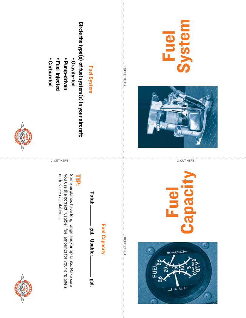
2. CUT HERE 2. CUT HERE 1. FOLD HERE 1. FOLD HERE Fuel Capacity Fuel System TIP: Some airplanes have long range and/or tip tanks. Make sure you use the correct “usable” fuel amounts for your airplane’s endurance calculations. Fuel Capacity Total: gal. Usable: gal. Fuel System Circle the type(s) of fuel system(s) in your aircraft: • Gravity-fed • Pump-driven • Fuel-injected • Carbureted
Transcript of Fuel System - AOPA · PDF fileFuel System Circle the ... • Pump-driven •...
2. CUT HERE 2. CUT HERE
1. F
OLD
HE
RE
1. F
OLD
HE
RE
Fuel
Ca
paci
tyFu
el
Syst
emTIP: Som
e airplanes have long range and/or tip tanks. Make sure
you use the correct “usable” fuel amounts for your airplane’s
endurance calculations.
Fuel Capacity
Total: gal. Usable:
gal.Fuel System
Circle the type(s) of fuel system(s) in your aircraft:
• Gravity-fed• Pum
p-driven• Fuel-injected• Carbureted

1. F
OLD
HE
RE
1. F
OLD
HE
RE
2. CUT HERE 2. CUT HERE
Fuel Drains and Locations
Num
ber of Drains: _______________
Locations: ______________________
________________________________
________________________________
Fuel Type,Weight, and Color
Type (e.g., avgas, jet): _______________________
W
eight: _____________lb./gal.
Color: ______________
Fuel
Typ
e,W
eigh
t, an
d
Colo
r
Fuel
Dr
ains
and
Loca
tions
Oil
(Min
./Max
./Typ
e/Qt
y.)
Engi
ne(M
ake,
Mod
el, H
P, R
PM)
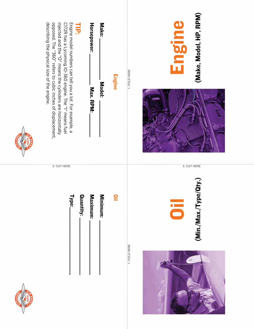
TIP: Engine m
odel numbers can tell you a lot. For exam
ple, a C
172R has a Lycom
ing IO-360
engine. The “I” means fuel
injected and the “O” m
eans the cylinders are horizontally opposed. The “360
” refers to cubic inches of displacement,
describing the physical size of the engine.
Engine
Make: ________________
Model: ______________
Horsepow
er: ____________ Max. RPM
: _________
Oil
Minim
um: _____________________
Maxim
um: _____________________
Quantity: ______________________
Type: __________________________
2. CUT HERE 2. CUT HERE
1. F
OLD
HE
RE
1. F
OLD
HE
RE

Elec
tric
alSy
stem
Mag
neto
Chec
kTIP: A
drop on one magneto but not the other (or no drop on either
magneto) could indicate a “hot m
ag,” which m
eans the engine could fire inadvertently after shutdow
n as a result of a broken or dam
aged P-lead or magneto sw
itch. It’s important to include a hot
mag check into your engine shutdow
n list.
Magneto Check
Runup RPM: ________
Max. RPM
Drop: __________
Max. Diff
erence Between Left and Right: _________
TIP: Electrical com
ponent amperage is listed on the faces of the
circuit breakers. Turning OFF the com
ponents with the largest
draw w
ill lengthen the life of the battery following an alternator
failure.
Electrical System
Alternator Voltage: ______Battery Voltage: _________
Alternator Amperage: _____________________________
Abnormal Indications and W
arnings:
_________________________________________________
1. F
OLD
HE
RE
1. F
OLD
HE
RE
2. CUT HERE 2. CUT HERE
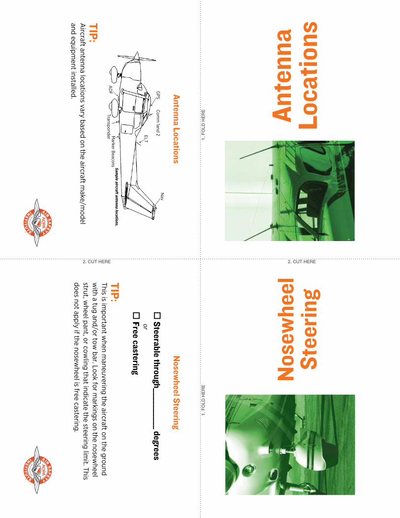
GPS
Com
m 1and 2ELT
Nav
Marker B
eaconsTransponder
AD
F Antenna Locations
TIP: A
ircraft antenna locations vary based on the aircraft make/m
odel and equipm
ent installed.
TIP: This is im
portant when m
aneuvering the aircraft on the ground w
ith a tug and/or tow bar. Look for m
arkings on the nosewheel
strut, wheel pant, or cow
ling that indicate the steering limit. This
does not apply if the nosewheel is free castering.
Nosew
heel Steering
Steerable through__________ degrees
or
Free castering
Sample aircraft antenna locations.
1. F
OLD
HE
RE
1. F
OLD
HE
RE
2. CUT HERE 2. CUT HERE
Nos
ewhe
elSt
eerin
gAn
tenn
aLo
catio
ns
TIP: M
aximum
ramp w
eight usually includes the weight of
fuel needed to taxi and complete the runup. This is w
hy the m
aximum
ramp w
eight may exceed the m
aximum
takeoff
weight in the norm
al category.
Maxim
um Ram
p Weight
__________________ lb.
Maxim
um Takeoff
Weight
__________________ lb.
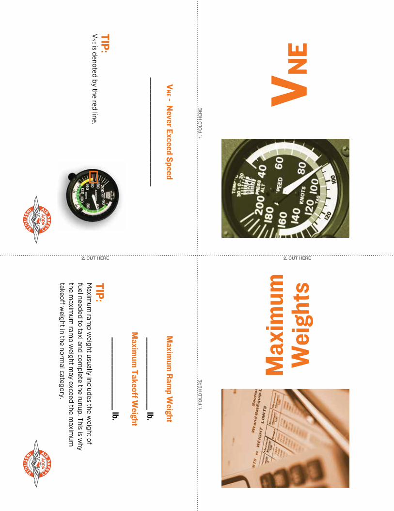
VN
E - Never Exceed Speed
___________________________
TIP: V
NE is denoted by the red line.
2. CUT HERE 2. CUT HERE
1. F
OLD
HE
RE
1. F
OLD
HE
RE
Max
imum
Wei
ghts
VNE
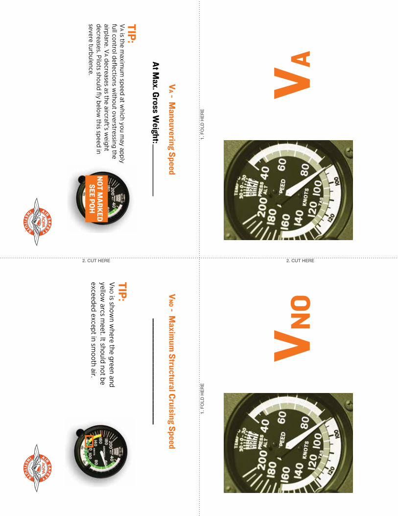
VA - M
aneuvering Speed
At Max. Gross W
eight:
TIP: V
a is the maxim
um speed at w
hich you may apply
full control deflections without overstressing the
airplane. Va decreases as the aircraft’s w
eight decreases. Pilots should fly below
this speed in severe turbulence.
VN
O - Maxim
um Structural Cruising Speed
__________________________
TIP: V
NO is show
n where the green and
yellow arcs m
eet. It should not be exceeded except in sm
ooth air.
1. F
OLD
HE
RE
1. F
OLD
HE
RE
2. CUT HERE 2. CUT HERE
VNO
VAN
OT MARKED
SEE POH
1. F
OLD
HE
RE
1. F
OLD
HE
RE
2. CUT HERE 2. CUT HERE
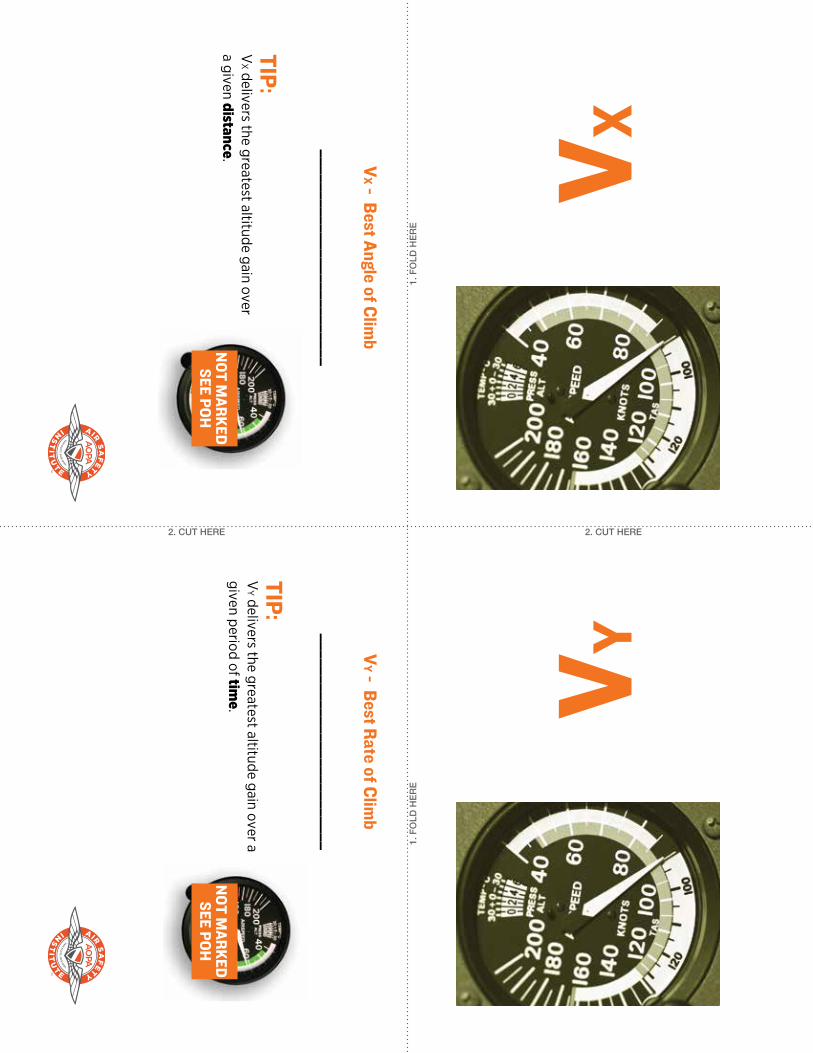
VYVXV
X - Best Angle of Climb
__________________________
TIP: V
X delivers the greatest altitude gain over a given distance.
VY - Best Rate of Clim
b
__________________________
TIP: V
Y delivers the greatest altitude gain over a given period of tim
e.N
OT MARKED
SEE POHN
OT MARKED
SEE POH
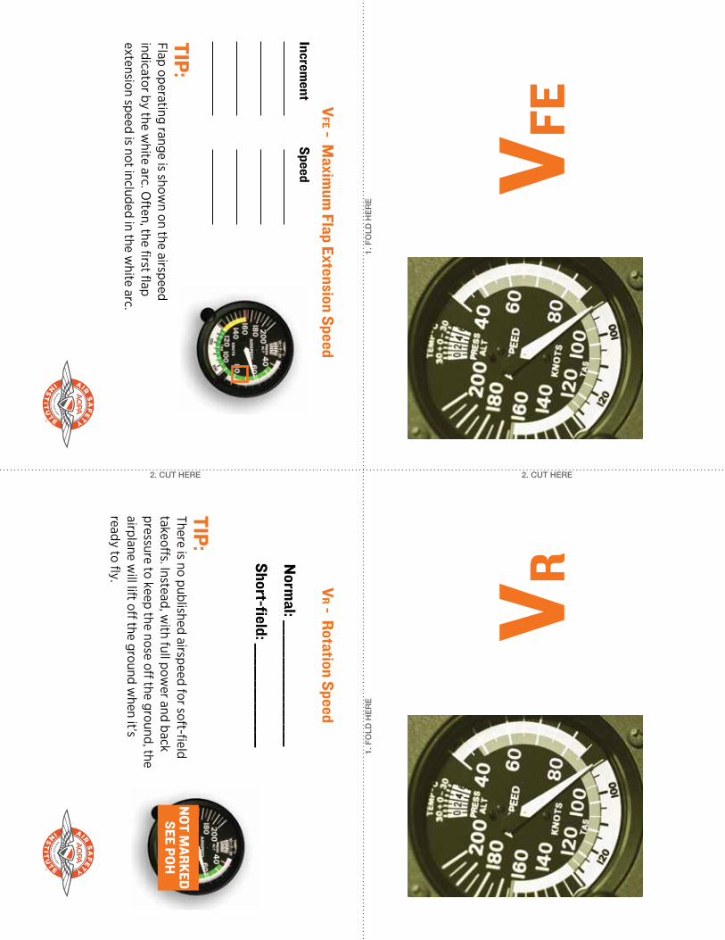
TIP: Flap operating range is show
n on the airspeed indicator by the w
hite arc. Often, the first flap
extension speed is not included in the white arc.
VFE - M
aximum
Flap Extension Speed
Increment
Speed
TIP: There is no published airspeed for soft-field takeoff
s. Instead, with full pow
er and back pressure to keep the nose off
the ground, the airplane w
ill lift off the ground w
hen it’s ready to fly. V
R - Rotation Speed
Norm
al: _________________
Short-field: ______________
1. F
OLD
HE
RE
1. F
OLD
HE
RE
2. CUT HERE 2. CUT HERE
VRVF
EN
OT MARKED
SEE POH
1. F
OLD
HE
RE
1. F
OLD
HE
RE
2. CUT HERE 2. CUT HERE
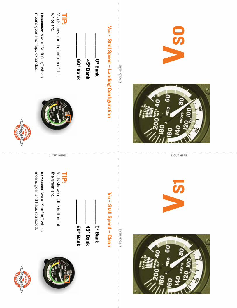
VS1
VSO
TIP: V
SO is shown on the bottom
of the w
hite arc.
Remem
ber: VSO = “Stuff
Out,” w
hich m
eans gear and flaps extended.
TIP: V
S1 is shown on the bottom
of the green arc.
Remem
ber: VS1 = “Stuff
In,” which
means gear and flaps retracted.
VSO - Stall Speed – Landing Configuration
__________0º Bank
__________45º Bank
__________60º Bank
VS1 - Stall Speed – Clean
__________0º Bank
__________45º Bank
__________60º Bank
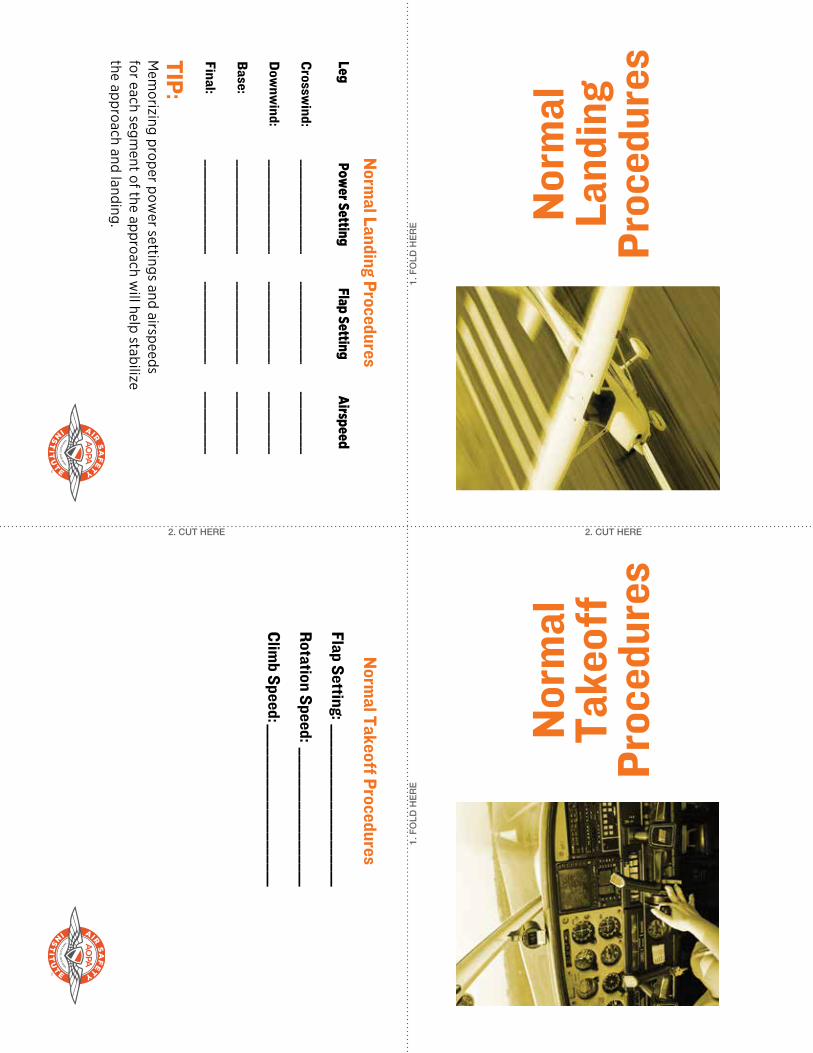
TIP: M
emorizing proper pow
er settings and airspeeds for each segm
ent of the approach will help stabilize
the approach and landing.
Norm
al Takeoff Procedures
Flap Setting: _____________________
Rotation Speed: __________________
Climb Speed: _____________________
1. F
OLD
HE
RE
1. F
OLD
HE
RE
2. CUT HERE 2. CUT HERE
Nor
mal
Ta
keoff
Pr
oced
ures
Nor
mal
La
ndin
gPr
oced
ures
Norm
al Landing Procedures
Leg Pow
er Setting Flap Setting
Airspeed
Crossw
ind: _________________________________________________
Dow
nwind: _________________________________________________
Base: ______________________________________________________
Final: ______________________________________________________
1. F
OLD
HE
RE
1. F
OLD
HE
RE
2. CUT HERE 2. CUT HERE
Shor
t-Fi
eld
Take
off
Proc
edur
es
Shor
t-Fi
eld
Land
ing
Proc
edur
es
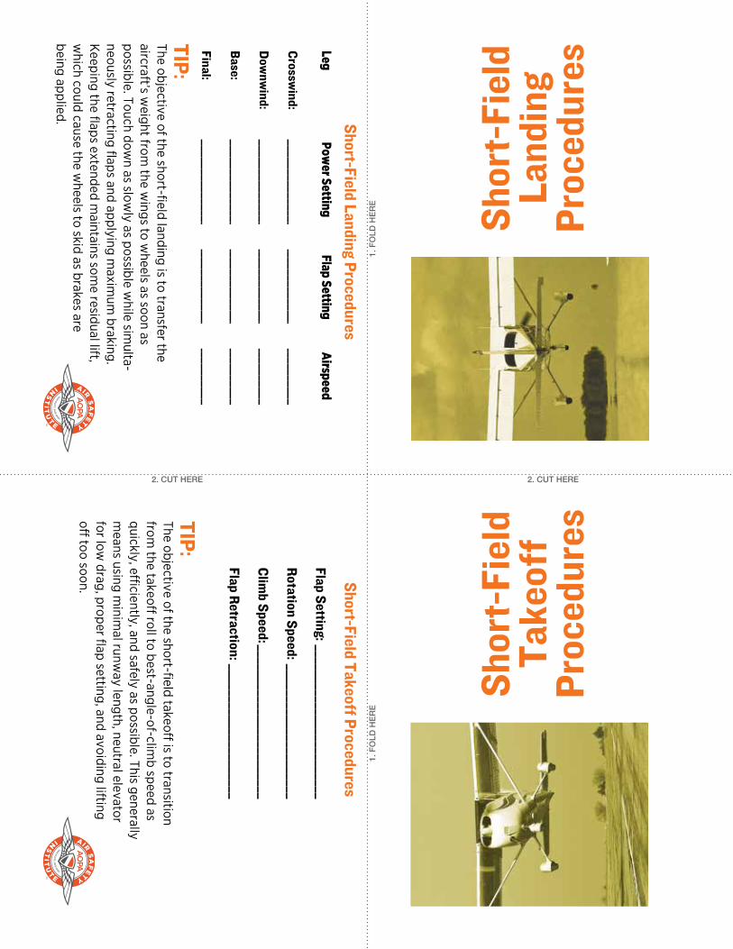
Short-Field Takeoff Procedures
Flap Setting: ________________________
Rotation Speed: _____________________
Climb Speed: ________________________
Flap Retraction: _____________________
TIP: The objective of the short-field landing is to transfer the aircraft’s w
eight from the w
ings to wheels as soon as
possible. Touch down as slow
ly as possible while sim
ulta-neously retracting flaps and applying m
aximum
braking. K
eeping the flaps extended maintains som
e residual lift, w
hich could cause the wheels to skid as brakes are
being applied.
TIP: The objective of the short-field takeoff
is to transition from
the takeoff roll to best-angle-of-clim
b speed as quickly, effi
ciently, and safely as possible. This generally m
eans using minim
al runway length, neutral elevator
for low drag, proper flap setting, and avoiding lifting
off too soon.
Short-Field Landing Procedures
Leg Pow
er Setting Flap Setting
Airspeed
Crossw
ind: _________________________________________________
Dow
nwind: _________________________________________________
Base: ______________________________________________________
Final: ______________________________________________________
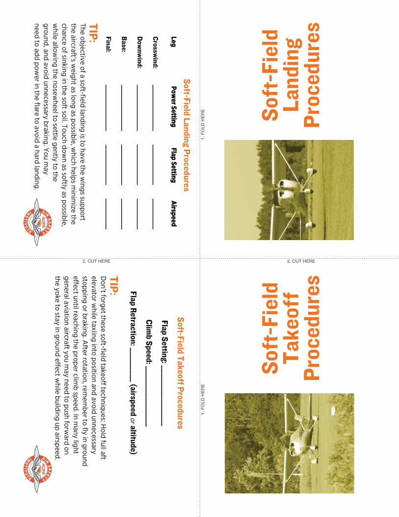
TIP: D
on’t forget these soft-field takeoff techniques: H
old full aft elevator w
hile taxiing into position and avoid unnecessary stopping or braking. A
fter rotation, remem
ber to fly in ground eff
ect until reaching the proper climb speed. In m
any light general aviation aircraft you m
ay need to push forward on
the yoke to stay in ground effect w
hile building up airspeed.
Soft-Field Takeoff Procedures
Flap Setting: ________________
Climb Speed: ________________
Flap Retraction: _________ (airspeed or altitude)
TIP: The objective of a soft-field landing is to have the w
ings support the aircraft’s w
eight as long as possible, which helps m
inimize the
chance of sinking in the soft soil. Touch down as softly as possible,
while allow
ing the nosewheel to settle gently to the
ground, and avoid unnecessary braking. You m
ay need to add pow
er in the flare to avoid a hard landing.
1. F
OLD
HE
RE
1. F
OLD
HE
RE
2. CUT HERE 2. CUT HERE
Soft
-Fie
ldTa
keoff
Pr
oced
ures
Soft
-Fie
ldLa
ndin
gPr
oced
ures
Soft-Field Landing Procedures
Leg Pow
er Setting Flap Setting
Airspeed
Crossw
ind: _________________________________________________
Dow
nwind: _________________________________________________
Base: ______________________________________________________
Final: ______________________________________________________
1. F
OLD
HE
RE
1. F
OLD
HE
RE
2. CUT HERE 2. CUT HEREM
axim
um
Dem
onst
rate
d Cr
ossw
ind
Co
mpo
nent
Best
Glid
e Sp
eed
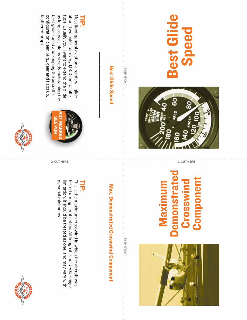
TIP: M
ost light general aviation aircraft will glide
about two m
iles for every 1,00
0 feet of alti-
tude. Usually you’ll w
ant to extend the glide as long as possible by strictly m
aintaining the best glide speed and keeping the aircraft’s configuration clean (e.g., gear and flaps up, feathered prop).
Best Glide Speed
__________________________
TIP: This is the m
aximum
crosswind in w
hich the aircraft was
tested during certification. Although it is not technically a
limitation, it should be treated as one, and m
ay vary with
personal minim
ums.
Max. Dem
onstrated Crosswind Com
ponent
__________________________
NOT M
ARKEDSEE POH
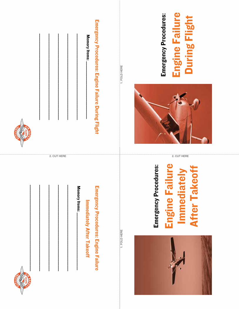
Emergency Procedures: Engine Failure During Flight
Mem
ory Items: ______________________________
_____________________________________________
_____________________________________________
_____________________________________________
_____________________________________________
_____________________________________________
Emergency Procedures: Engine Failure
Imm
ediately After TakeoffM
emory Item
s: ______________________________
_____________________________________________
_____________________________________________
_____________________________________________
_____________________________________________
_____________________________________________
1. F
OLD
HE
RE
1. F
OLD
HE
RE
2. CUT HERE 2. CUT HERE
Emer
genc
y Pr
oced
ures
:
Engi
ne F
ailu
re
Durin
g Fl
ight
Emer
genc
y Pr
oced
ures
:
Engi
ne F
ailu
re
Imm
edia
tely
Af
ter T
akeo
ff
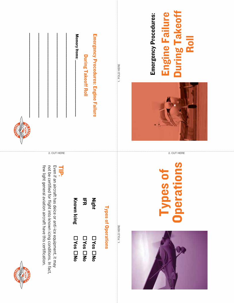
Emergency Procedures: Engine Failure
During Takeoff Roll
Mem
ory Items: ______________________________
_____________________________________________
_____________________________________________
_____________________________________________
_____________________________________________
_____________________________________________
TIP: Even if an aircraft has deice or anti-ice equipm
ent, it may
not be certified for flight into known icing conditions. In fact,
few light general aviation aircraft have this certification.
Types of Operations
N
ight
Yes
No
IFR
Yes
No
Know
n Icing Yes
No
1. F
OLD
HE
RE
1. F
OLD
HE
RE
2. CUT HERE 2. CUT HERE
Type
s of
Op
erat
ions
Emer
genc
y Pr
oced
ures
:
Engi
ne F
ailu
re
Durin
g Ta
keoff
Ro
ll

1. F
OLD
HE
RE
1. F
OLD
HE
RE
2. CUT HERE 2. CUT HEREEm
erge
ncy
Proc
edur
es:
Engi
ne F
ire
on S
tart
Emer
genc
y Pr
oced
ures
:
Engi
ne F
ire
in F
light
Emergency Procedures: Engine Fire on StartM
emory Item
s: ______________________________
_____________________________________________
_____________________________________________
_____________________________________________
_____________________________________________
_____________________________________________
Emergency Procedures: Engine Fire in FlightM
emory Item
s: ______________________________
_____________________________________________
_____________________________________________
_____________________________________________
_____________________________________________
_____________________________________________
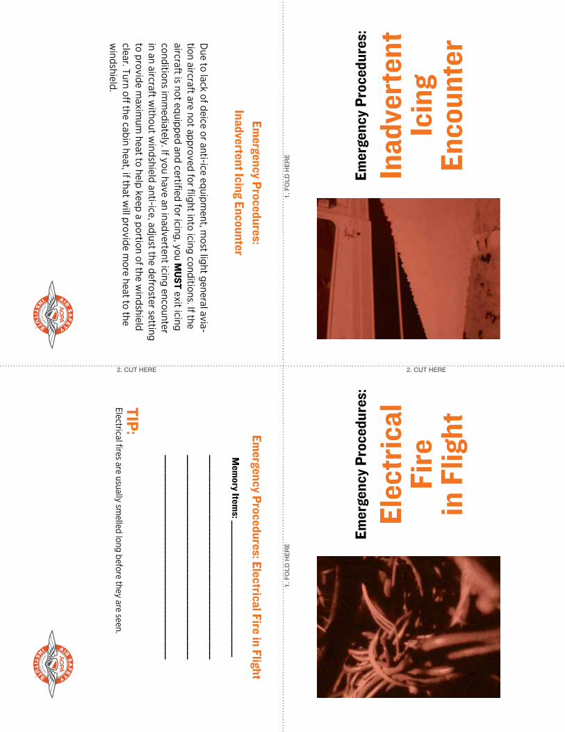
Due to lack of deice or anti-ice equipm
ent, most light general avia-
tion aircraft are not approved for flight into icing conditions. If the aircraft is not equipped and certified for icing, you M
UST exit icing conditions im
mediately. If you have an inadvertent icing encounter
in an aircraft without w
indshield anti-ice, adjust the defroster setting to provide m
aximum
heat to help keep a portion of the windshield
clear. Turn off the cabin heat, if that w
ill provide more heat to the
windshield.
Emergency Procedures:
Inadvertent Icing Encounter
TIP: Electrical fires are usually sm
elled long before they are seen.
Emergency Procedures: Electrical Fire in Flight
Mem
ory Items: ______________________________
_____________________________________________
_____________________________________________
_____________________________________________
1. F
OLD
HE
RE
1. F
OLD
HE
RE
2. CUT HERE 2. CUT HEREEm
erge
ncy
Proc
edur
es:
Elec
tric
al
Fire
in
Flig
ht
Emer
genc
y Pr
oced
ures
:
Inad
vert
ent
Icin
g En
coun
ter
2. CUT HERE 2. CUT HERE
1. F
OLD
HE
RE
1. F
OLD
HE
RE
Emer
genc
y Pr
oced
ures
:
Spin
Re
cove
ryw
ww
.airs
afet
yins
titut
e.or
g
For more than 60
years, the AO
PA A
ir Safety Institute has been producing free program
s to help all pilots fly safer. From ground-
breaking online courses to popular videos and live seminars, A
SI covers the spectrum
of aviation safety education.
ww
w.airsafetyinstitute.org
TIP: Som
e pilots comm
it to mem
ory the PARE acronym, w
hich m
eans Power-to idle, Ailerons-neutral, R
udder-full opposite the spin, Elevator-forw
ard to break the stall.
Spin RecoveryM
emory Item
s: ______________________________
_____________________________________________
_____________________________________________
_____________________________________________
©20
17 Aircraft O
wners and Pilots A
ssociation