Flexible Pavement Rehabilitation Using...
29
FLEXIBLE PAVEMENT REHABILITATION USING PULVERIZATION California Department of Transportation Division of Pavement Office of Pavement Engineering June 2008
Transcript of Flexible Pavement Rehabilitation Using...
FLEXIBLE PAVEMENT REHABILITATION
USING PULVERIZATION
California Department of Transportation Division of Pavement
Office of Pavement Engineering
June 2008
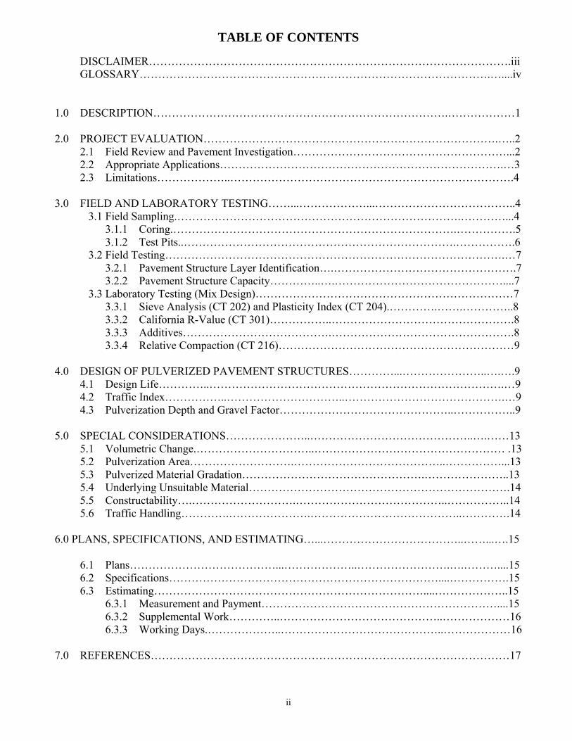
TABLE OF CONTENTS
ii
DISCLAIMER…………………………………………………………………………………….iii GLOSSARY………………………………………………………………………………….…....iv
1.0 DESCRIPTION…………………………………………………………………….………………1 2.0 PROJECT EVALUATION…………………………………………………………………….…..2
2.1 Field Review and Pavement Investigation…………………………………………………...2 2.2 Appropriate Applications………………………………………………………………….…3 2.3 Limitations………………..………………………………………………………………….4
3.0 FIELD AND LABORATORY TESTING……...………………...………………………………..4
3.1 Field Sampling.………………………………………………………………….…………...4 3.1.1 Coring.………………………………………………………………….…………….5 3.1.2 Test Pits..……………………………………………………………….…………….6
3.2 Field Testing……………………………………………………………………………….…7 3.2.1 Pavement Structure Layer Identification….………………………………………….7 3.2.2 Pavement Structure Capacity…………..….………………………………………....7
3.3 Laboratory Testing (Mix Design)……………………………………………………………7 3.3.1 Sieve Analysis (CT 202) and Plasticity Index (CT 204).………….…….…………..8 3.3.2 California R-Value (CT 301)……………..………………………………………….8 3.3.3 Additives………………………………….………………………………………….8 3.3.4 Relative Compaction (CT 216)………………………………………………………9
4.0 DESIGN OF PULVERIZED PAVEMENT STRUCTURES…………...…………………..….….9
4.1 Design Life…………..…………………………………………………………………….…9 4.2 Traffic Index……………..…………………………..…………………………………….…9 4.3 Pulverization Depth and Gravel Factor………………………………………..……………..9
5.0 SPECIAL CONSIDERATIONS…………………..……………………………………..….……13
5.1 Volumetric Change.…………………………..…………………………………………… .13 5.2 Pulverization Area……………………….…………………………………..……………...13 5.3 Pulverized Material Gradation………………………………………….…………………..13 5.4 Underlying Unsuitable Material…………………………………………………………….14 5.5 Constructability….……………………….…………………………………..……………..14 5.6 Traffic Handling………….………………….…………………………………..………….14
6.0 PLANS, SPECIFICATIONS, AND ESTIMATING…...………………………………..……...….15 6.1 Plans…………………………………...………………..…………………….….………....15
6.2 Specifications………………………………………………………………....…………….15 6.3 Estimating………………………………………………………………....………………..15
6.3.1 Measurement and Payment………………………………………………………....15 6.3.2 Supplemental Work…………..……………………………………..………………16 6.3.3 Working Days.………………..……………………………………..………………16
7.0 REFERENCES……………………………………………………………………………………17
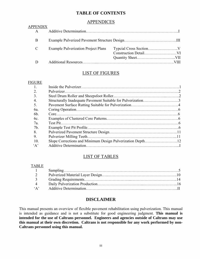
TABLE OF CONTENTS
APPENDICES APPENDIX
A Additive Determination……………………………………………………………..I
B Example Pulverized Pavement Structure Design………………………………….III
C Example Pulverization Project Plans Typcial Cross Section…………………..V Construction Detail………………….…VI Quantity Sheet.………………………..VII
D Additional Resources………....………………………………………………….VIII
LIST OF FIGURES
FIGURE
1. Inside the Pulverizer…………………………………………………………………1 2. Pulverizer……………………………………………………………………………2 3. Steel Drum Roller and Sheepsfoot Roller...………………………………...……….2 4. Structurally Inadequate Pavement Suitable for Pulverization………………………3 5. Pavement Surface Rutting Suitable for Pulverization………………………………4 6a. Coring Operation……………………………………………………………………6 6b. Core…………………………………………………………………………………6 6c. Examples of Clustered Core Patterns.………………………………………………6 7a. Test Pit………………………………………………………………………………6 7b. Example Test Pit Profile…………………………………………………………….6 8. Pulverized Pavement Structure Design…………………………………………….11 9. Pulverizer Milling Teeth…………………………………………………………...11 10. Slope Corrections and Minimum Design Pulverization Depth…………………….12
‘A’ Additive Determination……………………………………………………………...I
LIST OF TABLES
TABLE 1 Sampling….…………………………………………………………………………5 2 Pulverized Material Layer Design…...…………………………………………….10 3 Grading Requirements.……………………………...……………………………..14 4 Daily Pulverization Production……………………………...……………………..16
‘A’ Additive Determination……………………………………...……………………..II
DISCLAIMER This manual presents an overview of flexible pavement rehabilitation using pulverization. This manual is intended as guidance and is not a substitute for good engineering judgment. This manual is intended for the use of Caltrans personnel. Engineers and agencies outside of Caltrans may use this manual at their own discretion. Caltrans is not responsible for any work performed by non-Caltrans personnel using this manual.
iii
GLOSSARY
iv
Alligator Cracking — Also referred to as fatigue cracking. Load related distress caused by inadequate structural support. Rated as ‘A’, ‘B’, or ‘C’. Alligator ‘A’ cracking is a single longitudinal crack in a wheel path. Alligator ‘B’ cracking is a series of interconnecting or interlaced cracks forming small polygons in a wheel path. Alligator ‘C’ cracking is a pattern of interconnected or interlaced cracks outside the wheel paths.6 Dynaflect — Trailer mounted pavement deflection measuring device. Uses a 1,000 pound oscillating load application. Not in widespread use within Caltrans. Dynamic Cone Penetrometer (DCP) — The standard DCP is a hand-held device featuring a 17.6 pound hammer which is raised and dropped from a height of 22.6 inches along a steel rod. The impact of the hammer drives a 60° conical tip into a layer of granular or fine-grained material. The associated depth of penetration is plotted against the number of blows, indicating the layer thickness and shear strength of the material. Falling Weight Deflectometer (FWD) — Pavement deflection measuring device. Applies a specified impulse load (Caltrans typically uses 9,000 pounds) to the pavement surface. May be mounted on a trailer or truck. Gravel Equivalent (GE) — The thickness of gravel (or aggregate subbase) required to prevent deformation in the underlying layer from a traffic load. Gravel Factor (Gf) — The relative strength of a material compared to gravel. Hot Mix Asphalt (HMA) — Formerly known as “asphalt concrete” or “AC.” A material used for flexible pavement consisting of dense-graded aggregate mixed with asphalt binder. Pavement Structure — Formerly known as “structural section.” Consists of the layers above the subgrade that support traffic loads. Pulverization — Mechanized process that transforms the existing flexible pavement surface layer and a portion of the underlying granular layer into a uniform granular material suitable for use as a base layer. Open-Graded Friction Course (OGFC) — Formerly known as open-graded asphalt concrete (OGAC). OGFC is a free draining HMA mixture with few fine-sized aggregate particles. Typically placed as a thin surface wearing course. For design purposes, OGFC is not considered to make a structural contribution to the pavement structure. Resistance Value (R-value) — A measure of resistance to deformation under loading of saturated soil. Rubberized Hot Mix Asphalt (RHMA) — Formerly known as rubberized asphalt concrete (RAC). Material produced for hot mix applications by mixing asphalt rubber binder (a combination of asphalt binder and crumb rubber modifier) with graded aggregate. The most commonly used gradations are gap-graded (RHMA-G) and open-graded (RHMA-O). For added durability, rubberized open-graded with a higher binder content (RHMA-O-HB) can be used. Stress Absorbing Membrane Interlayer (SAMI) — The two types used by Caltrans are geosynthetic fabric (SAMI-F) and rubberized (SAMI-R), which is an application of asphalt rubber binder and coated aggregate screenings. SAMI-F is also currently referred to as geosynthetic pavement interlayer (GPI) and was formerly known as pavement reinforcing fabric (PRF). Traffic Index (TI) — The Traffic Index (TI) is a measure of the number of 18 kip Equivalent Single Axle Loads (ESALs) expected in the traffic lane over the pavement design life of the facility. The TI does not vary linearly with ESALs and is determined to the nearest 0.5.
1.0 DESCRIPTION
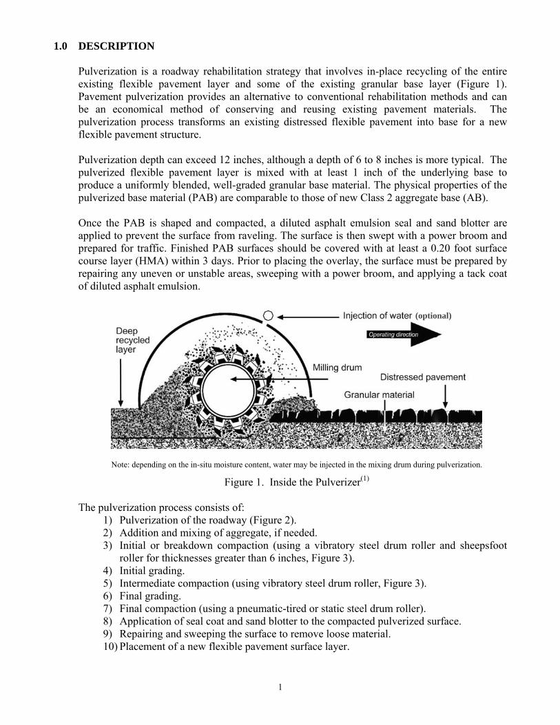
Pulverization is a roadway rehabilitation strategy that involves in-place recycling of the entire existing flexible pavement layer and some of the existing granular base layer (Figure 1). Pavement pulverization provides an alternative to conventional rehabilitation methods and can be an economical method of conserving and reusing existing pavement materials. The pulverization process transforms an existing distressed flexible pavement into base for a new flexible pavement structure. Pulverization depth can exceed 12 inches, although a depth of 6 to 8 inches is more typical. The pulverized flexible pavement layer is mixed with at least 1 inch of the underlying base to produce a uniformly blended, well-graded granular base material. The physical properties of the pulverized base material (PAB) are comparable to those of new Class 2 aggregate base (AB). Once the PAB is shaped and compacted, a diluted asphalt emulsion seal and sand blotter are applied to prevent the surface from raveling. The surface is then swept with a power broom and prepared for traffic. Finished PAB surfaces should be covered with at least a 0.20 foot surface course layer (HMA) within 3 days. Prior to placing the overlay, the surface must be prepared by repairing any uneven or unstable areas, sweeping with a power broom, and applying a tack coat of diluted asphalt emulsion.
(optional)
Note: depending on the in-situ moisture content, water may be injected in the mixing drum during pulverization.
Figure 1. Inside the Pulverizer(1) The pulverization process consists of:
1) Pulverization of the roadway (Figure 2). 2) Addition and mixing of aggregate, if needed. 3) Initial or breakdown compaction (using a vibratory steel drum roller and sheepsfoot
roller for thicknesses greater than 6 inches, Figure 3). 4) Initial grading. 5) Intermediate compaction (using vibratory steel drum roller, Figure 3). 6) Final grading. 7) Final compaction (using a pneumatic-tired or static steel drum roller). 8) Application of seal coat and sand blotter to the compacted pulverized surface. 9) Repairing and sweeping the surface to remove loose material. 10) Placement of a new flexible pavement surface layer.
1
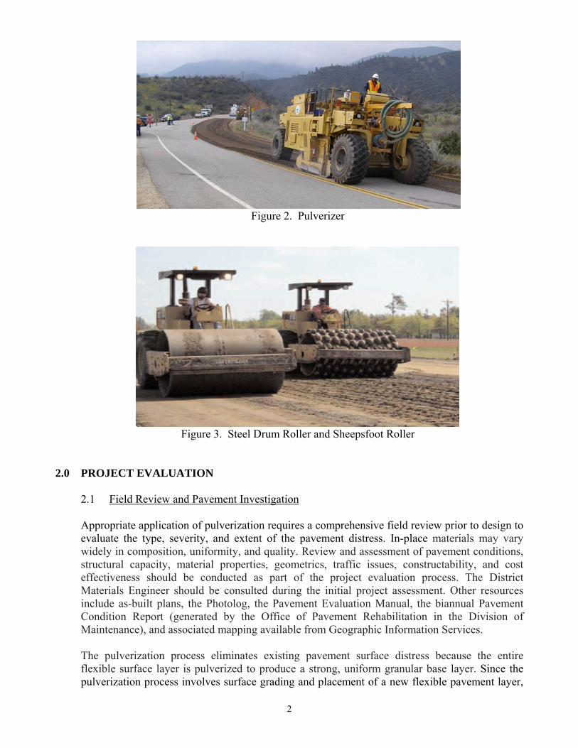
Figure 2. Pulverizer
Figure 3. Steel Drum Roller and Sheepsfoot Roller 2.0 PROJECT EVALUATION
2.1 Field Review and Pavement Investigation Appropriate application of pulverization requires a comprehensive field review prior to design to evaluate the type, severity, and extent of the pavement distress. In-place materials may vary widely in composition, uniformity, and quality. Review and assessment of pavement conditions, structural capacity, material properties, geometrics, traffic issues, constructability, and cost effectiveness should be conducted as part of the project evaluation process. The District Materials Engineer should be consulted during the initial project assessment. Other resources include as-built plans, the Photolog, the Pavement Evaluation Manual, the biannual Pavement Condition Report (generated by the Office of Pavement Rehabilitation in the Division of Maintenance), and associated mapping available from Geographic Information Services. The pulverization process eliminates existing pavement surface distress because the entire flexible surface layer is pulverized to produce a strong, uniform granular base layer. Since the pulverization process involves surface grading and placement of a new flexible pavement layer,
2
it allows for changes to existing grades. As such, during the field review and evaluation, note any drainage problems, utility locations or conflicts, and recommendations to change profiles and cross slopes. Also, identify potential staging areas and consider potential access problems for the pulverizer with respect to any confined or miscellaneous paved areas adjacent to the traveled way (such as turnouts, maintenance pullouts, vista points, etc). 2.2 Appropriate Applications Pulverization can treat a variety of project conditions, but is most cost effective on surfaces requiring digouts of 20% or more by paving area. Appropriate applications include: • Structurally inadequate pavement sections, which would otherwise require a thick overlay, as
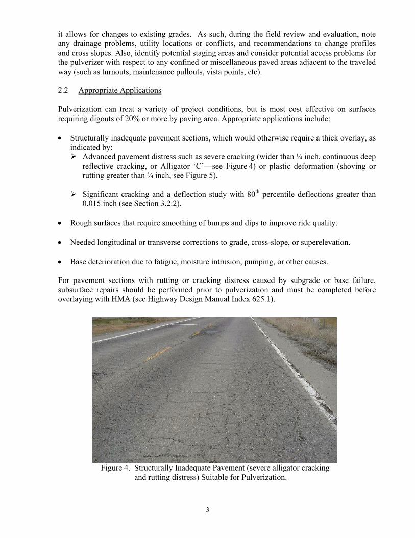
indicated by: Advanced pavement distress such as severe cracking (wider than ¼ inch, continuous deep
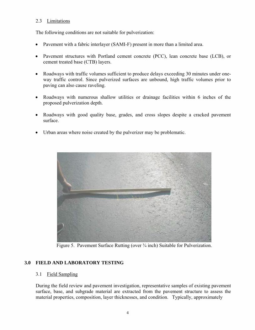
reflective cracking, or Alligator ‘C’—see Figure 4) or plastic deformation (shoving or rutting greater than ¾ inch, see Figure 5).
Significant cracking and a deflection study with 80th percentile deflections greater than
0.015 inch (see Section 3.2.2).
• Rough surfaces that require smoothing of bumps and dips to improve ride quality.
• Needed longitudinal or transverse corrections to grade, cross-slope, or superelevation.
• Base deterioration due to fatigue, moisture intrusion, pumping, or other causes.
For pavement sections with rutting or cracking distress caused by subgrade or base failure, subsurface repairs should be performed prior to pulverization and must be completed before overlaying with HMA (see Highway Design Manual Index 625.1).
Figure 4. Structurally Inadequate Pavement (severe alligator cracking and rutting distress) Suitable for Pulverization.
3
2.3 Limitations The following conditions are not suitable for pulverization:
• Pavement with a fabric interlayer (SAMI-F) present in more than a limited area. • Pavement structures with Portland cement concrete (PCC), lean concrete base (LCB), or
cement treated base (CTB) layers.
• Roadways with traffic volumes sufficient to produce delays exceeding 30 minutes under one-way traffic control. Since pulverized surfaces are unbound, high traffic volumes prior to paving can also cause raveling.
• Roadways with numerous shallow utilities or drainage facilities within 6 inches of the
proposed pulverization depth.
• Roadways with good quality base, grades, and cross slopes despite a cracked pavement surface.
• Urban areas where noise created by the pulverizer may be problematic.
Figure 5. Pavement Surface Rutting (over ¾ inch) Suitable for Pulverization. 3.0 FIELD AND LABORATORY TESTING
3.1 Field Sampling During the field review and pavement investigation, representative samples of existing pavement surface, base, and subgrade material are extracted from the pavement structure to assess the material properties, composition, layer thicknesses, and condition. Typically, approximately
4
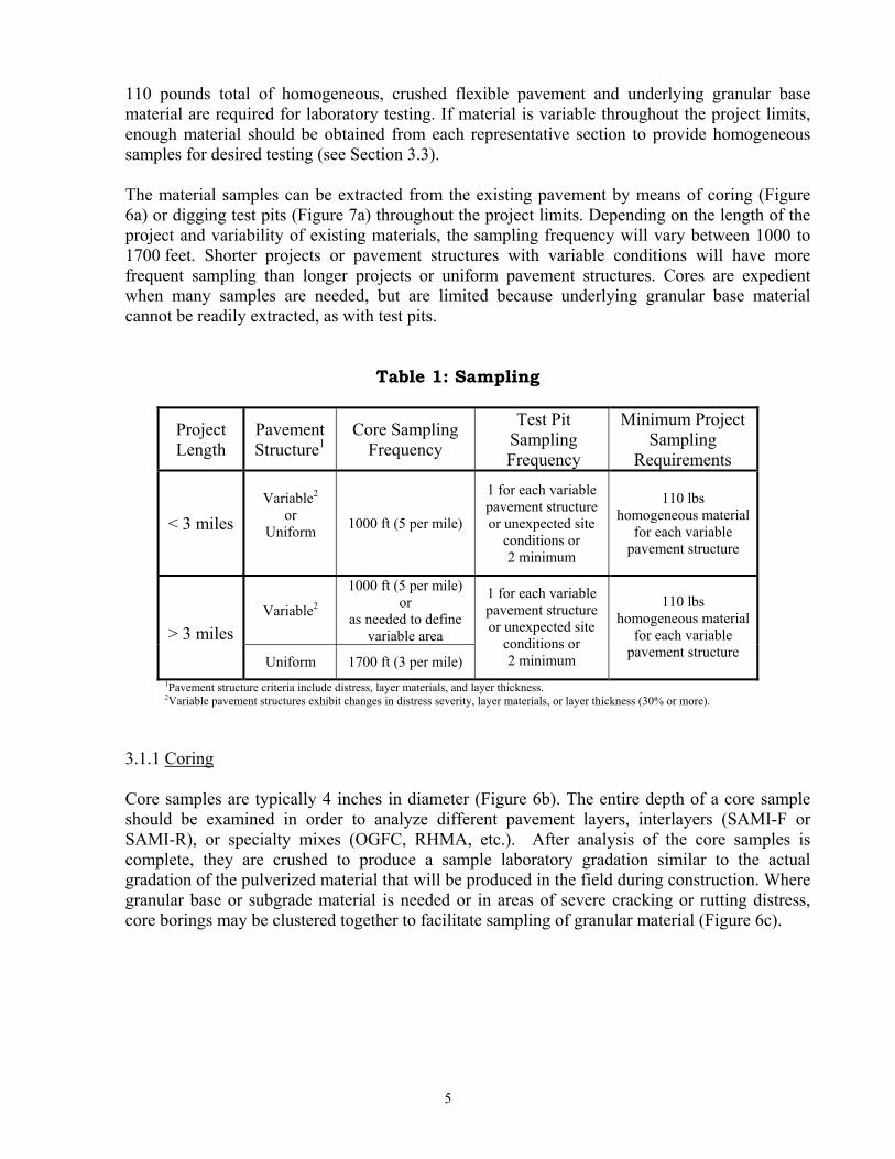
110 pounds total of homogeneous, crushed flexible pavement and underlying granular base material are required for laboratory testing. If material is variable throughout the project limits, enough material should be obtained from each representative section to provide homogeneous samples for desired testing (see Section 3.3). The material samples can be extracted from the existing pavement by means of coring (Figure 6a) or digging test pits (Figure 7a) throughout the project limits. Depending on the length of the project and variability of existing materials, the sampling frequency will vary between 1000 to 1700 feet. Shorter projects or pavement structures with variable conditions will have more frequent sampling than longer projects or uniform pavement structures. Cores are expedient when many samples are needed, but are limited because underlying granular base material cannot be readily extracted, as with test pits.
Table 1: Sampling
Project Length
Pavement Structure1
Core Sampling Frequency
Test Pit Sampling Frequency
Minimum Project Sampling
Requirements
< 3 miles Variable2
or Uniform
1000 ft (5 per mile)
1 for each variable pavement structure or unexpected site
conditions or 2 minimum
110 lbs homogeneous material
for each variable pavement structure
Variable2
1000 ft (5 per mile) or
as needed to define variable area
> 3 miles
Uniform 1700 ft (3 per mile)
1 for each variable pavement structure or unexpected site
conditions or 2 minimum
110 lbs homogeneous material
for each variable pavement structure
1Pavement structure criteria include distress, layer materials, and layer thickness. 2Variable pavement structures exhibit changes in distress severity, layer materials, or layer thickness (30% or more).
3.1.1 Coring Core samples are typically 4 inches in diameter (Figure 6b). The entire depth of a core sample should be examined in order to analyze different pavement layers, interlayers (SAMI-F or SAMI-R), or specialty mixes (OGFC, RHMA, etc.). After analysis of the core samples is complete, they are crushed to produce a sample laboratory gradation similar to the actual gradation of the pulverized material that will be produced in the field during construction. Where granular base or subgrade material is needed or in areas of severe cracking or rutting distress, core borings may be clustered together to facilitate sampling of granular material (Figure 6c).
5
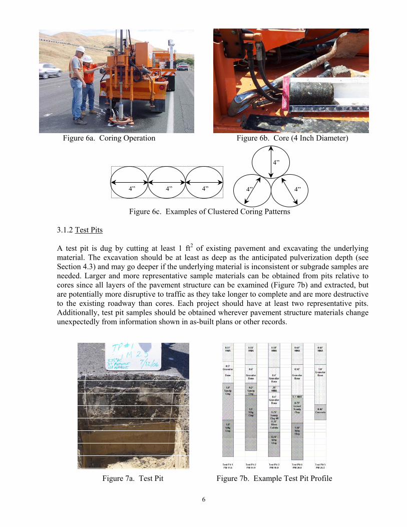
Figure 6a. Coring Operation Figure 6b. Core (4 Inch Diameter)
Figure 6c. Examples of Clustered Coring Patterns
4”
4”
4”4” 4” 4”
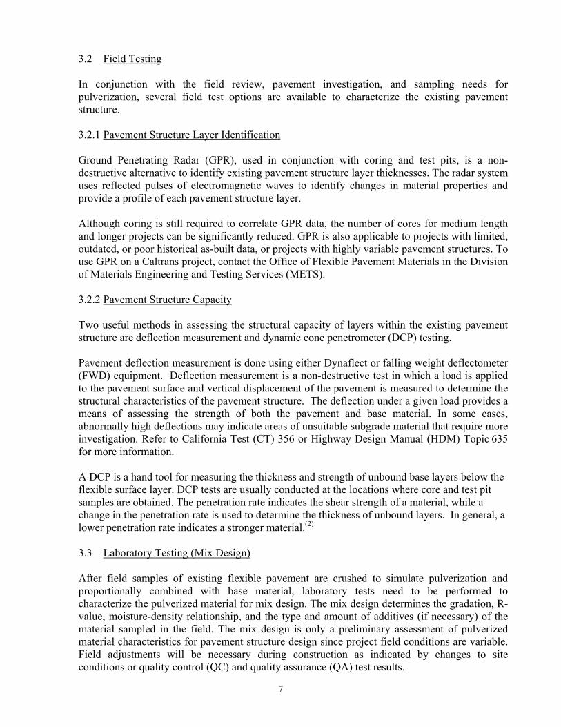
3.1.2 Test Pits A test pit is dug by cutting at least 1 ft2 of existing pavement and excavating the underlying material. The excavation should be at least as deep as the anticipated pulverization depth (see Section 4.3) and may go deeper if the underlying material is inconsistent or subgrade samples are needed. Larger and more representative sample materials can be obtained from pits relative to cores since all layers of the pavement structure can be examined (Figure 7b) and extracted, but are potentially more disruptive to traffic as they take longer to complete and are more destructive to the existing roadway than cores. Each project should have at least two representative pits. Additionally, test pit samples should be obtained wherever pavement structure materials change unexpectedly from information shown in as-built plans or other records.
Figure 7a. Test Pit Figure 7b. Example Test Pit Profile
6
3.2 Field Testing In conjunction with the field review, pavement investigation, and sampling needs for pulverization, several field test options are available to characterize the existing pavement structure. 3.2.1 Pavement Structure Layer Identification Ground Penetrating Radar (GPR), used in conjunction with coring and test pits, is a non-destructive alternative to identify existing pavement structure layer thicknesses. The radar system uses reflected pulses of electromagnetic waves to identify changes in material properties and provide a profile of each pavement structure layer. Although coring is still required to correlate GPR data, the number of cores for medium length and longer projects can be significantly reduced. GPR is also applicable to projects with limited, outdated, or poor historical as-built data, or projects with highly variable pavement structures. To use GPR on a Caltrans project, contact the Office of Flexible Pavement Materials in the Division of Materials Engineering and Testing Services (METS). 3.2.2 Pavement Structure Capacity Two useful methods in assessing the structural capacity of layers within the existing pavement structure are deflection measurement and dynamic cone penetrometer (DCP) testing.
Pavement deflection measurement is done using either Dynaflect or falling weight deflectometer (FWD) equipment. Deflection measurement is a non-destructive test in which a load is applied to the pavement surface and vertical displacement of the pavement is measured to determine the structural characteristics of the pavement structure. The deflection under a given load provides a means of assessing the strength of both the pavement and base material. In some cases, abnormally high deflections may indicate areas of unsuitable subgrade material that require more investigation. Refer to California Test (CT) 356 or Highway Design Manual (HDM) Topic 635 for more information. A DCP is a hand tool for measuring the thickness and strength of unbound base layers below the flexible surface layer. DCP tests are usually conducted at the locations where core and test pit samples are obtained. The penetration rate indicates the shear strength of a material, while a change in the penetration rate is used to determine the thickness of unbound layers. In general, a lower penetration rate indicates a stronger material.(2)
3.3 Laboratory Testing (Mix Design) After field samples of existing flexible pavement are crushed to simulate pulverization and proportionally combined with base material, laboratory tests need to be performed to characterize the pulverized material for mix design. The mix design determines the gradation, R-value, moisture-density relationship, and the type and amount of additives (if necessary) of the material sampled in the field. The mix design is only a preliminary assessment of pulverized material characteristics for pavement structure design since project field conditions are variable. Field adjustments will be necessary during construction as indicated by changes to site conditions or quality control (QC) and quality assurance (QA) test results.
7
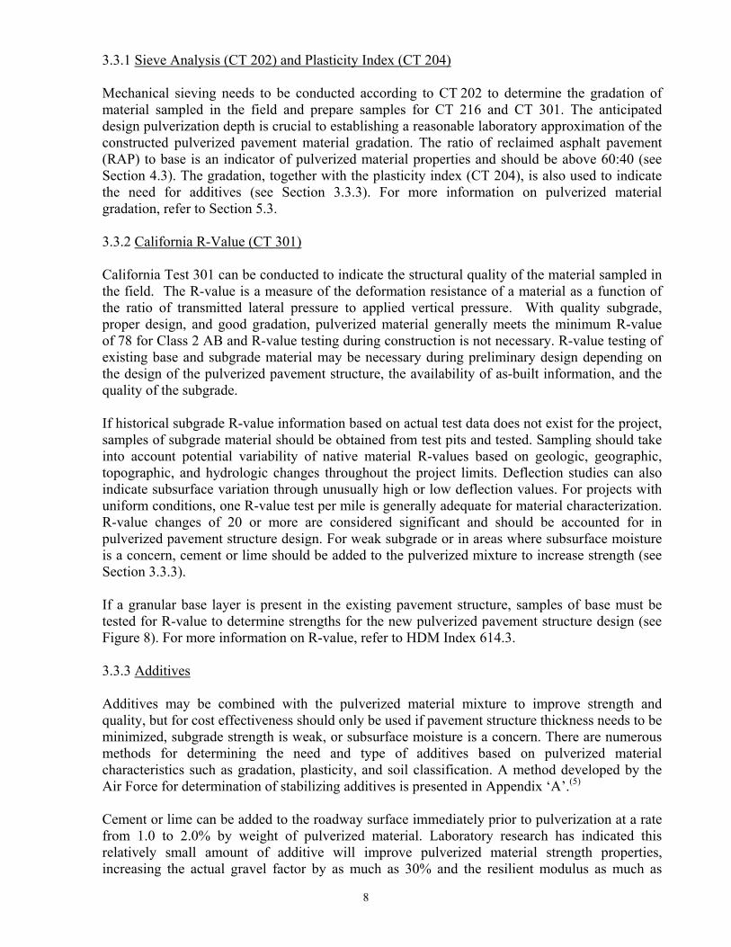
3.3.1 Sieve Analysis (CT 202) and Plasticity Index (CT 204)
Mechanical sieving needs to be conducted according to CT 202 to determine the gradation of material sampled in the field and prepare samples for CT 216 and CT 301. The anticipated design pulverization depth is crucial to establishing a reasonable laboratory approximation of the constructed pulverized pavement material gradation. The ratio of reclaimed asphalt pavement (RAP) to base is an indicator of pulverized material properties and should be above 60:40 (see Section 4.3). The gradation, together with the plasticity index (CT 204), is also used to indicate the need for additives (see Section 3.3.3). For more information on pulverized material gradation, refer to Section 5.3. 3.3.2 California R-Value (CT 301)
California Test 301 can be conducted to indicate the structural quality of the material sampled in the field. The R-value is a measure of the deformation resistance of a material as a function of the ratio of transmitted lateral pressure to applied vertical pressure. With quality subgrade, proper design, and good gradation, pulverized material generally meets the minimum R-value of 78 for Class 2 AB and R-value testing during construction is not necessary. R-value testing of existing base and subgrade material may be necessary during preliminary design depending on the design of the pulverized pavement structure, the availability of as-built information, and the quality of the subgrade. If historical subgrade R-value information based on actual test data does not exist for the project, samples of subgrade material should be obtained from test pits and tested. Sampling should take into account potential variability of native material R-values based on geologic, geographic, topographic, and hydrologic changes throughout the project limits. Deflection studies can also indicate subsurface variation through unusually high or low deflection values. For projects with uniform conditions, one R-value test per mile is generally adequate for material characterization. R-value changes of 20 or more are considered significant and should be accounted for in pulverized pavement structure design. For weak subgrade or in areas where subsurface moisture is a concern, cement or lime should be added to the pulverized mixture to increase strength (see Section 3.3.3). If a granular base layer is present in the existing pavement structure, samples of base must be tested for R-value to determine strengths for the new pulverized pavement structure design (see Figure 8). For more information on R-value, refer to HDM Index 614.3. 3.3.3 Additives Additives may be combined with the pulverized material mixture to improve strength and quality, but for cost effectiveness should only be used if pavement structure thickness needs to be minimized, subgrade strength is weak, or subsurface moisture is a concern. There are numerous methods for determining the need and type of additives based on pulverized material characteristics such as gradation, plasticity, and soil classification. A method developed by the Air Force for determination of stabilizing additives is presented in Appendix ‘A’.(5) Cement or lime can be added to the roadway surface immediately prior to pulverization at a rate from 1.0 to 2.0% by weight of pulverized material. Laboratory research has indicated this relatively small amount of additive will improve pulverized material strength properties, increasing the actual gravel factor by as much as 30% and the resilient modulus as much as
8
50%.(3) Using higher amounts of additive can cause brittleness and shrinkage cracking. If cement is used as an additive, grading and compacting must be completed before the material sets up and no traffic or heavy contractor equipment is allowed on the pulverized surface for at least 1 hour following compaction. If the material characterization indicates a poorly graded or plastic material, a granular material such as Class 2 AB or a fine material such as fly ash or kiln dust may be added to improve the pulverized material characteristics. More commonly, Class 2 AB may be needed to provide additional material for shoulder widening or profile or cross slope corrections (see Figure 10). 3.3.4 Relative Compaction (CT 216)
During construction, the relative compaction of the pulverized material layer will be determined according to CT 216. In order to obtain the wet test maximum density and establish the optimum moisture content, laboratory compaction tests are first conducted during the mix design to determine the moisture-density relationship of the pulverized material. A minimum of 45 pounds of homogeneous material is needed for CT 216.
4.0 DESIGN OF PULVERIZED PAVEMENT STRUCTURES
The design of the flexible pavement structure follows pavement investigation, field-testing, and laboratory testing. Although pulverization is a process for rehabilitation of an existing road, the design process is similar to that for a new pavement since the pavement structure is being reconstructed from the base up, with the pulverized materials forming a new base for the new flexible pavement layer. For design purposes, material below the pulverization depth can be considered subgrade, aggregate subbase, or aggregate base depending on test R-values (see Figure 8). Topic 633 of the HDM describes the engineering procedures for new design of flexible pavement structures based on gravel equivalent (GE) and gravel factor (Gf), and Appendix ‘B’ provides an example pulverized pavement structure design.
4.1 Design Life The expected design life of the pavement structure is related to the pulverization depth and the type and thickness of the new flexible surface layer. Pulverization projects should be designed with a minimum pavement design life of 20 years, unless a life cycle cost analysis indicates a 40-year pavement design life is more cost effective. 4.2 Traffic Index (TI) Pavement design requires knowledge of anticipated traffic volumes and loading, which dictate the pavement structure requirements. Gather available traffic information and see HDM Topic 613 for procedures to determine the traffic index for the design life. 4.3 Pulverization Depth and Gravel Factor (Gf) Preliminary research being conducted by the University of California Pavement Research Center indicates that pulverized material with a high percentage of RAP has similar characteristics (shear strength, stiffness, and rutting resistance) to Class 2 AB.(6) The pulverized material (PAB) is stronger if it consists primarily of reclaimed asphalt pavement (RAP) as opposed to granular
9
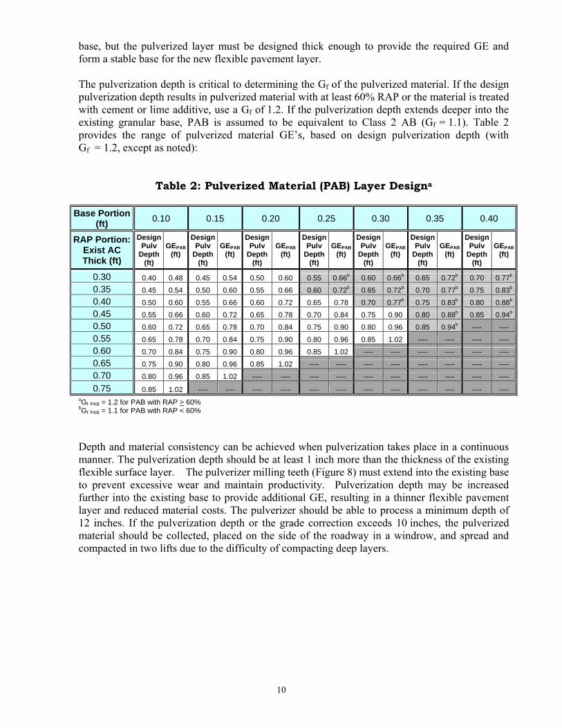
base, but the pulverized layer must be designed thick enough to provide the required GE and form a stable base for the new flexible pavement layer. The pulverization depth is critical to determining the Gf of the pulverized material. If the design pulverization depth results in pulverized material with at least 60% RAP or the material is treated with cement or lime additive, use a Gf of 1.2. If the pulverization depth extends deeper into the existing granular base, PAB is assumed to be equivalent to Class 2 AB (Gf = 1.1). Table 2 provides the range of pulverized material GE’s, based on design pulverization depth (with Gf = 1.2, except as noted):
Table 2: Pulverized Material (PAB) Layer Designa
Base Portion (ft) 0.10 0.15 0.20 0.25 0.30 0.35 0.40
RAP Portion: Exist AC Thick (ft)
Design Pulv
Depth (ft)
GEPAB (ft)
Design Pulv
Depth (ft)
GEPAB (ft)
Design Pulv
Depth (ft)
GEPAB (ft)
Design Pulv
Depth (ft)
GEPAB (ft)
Design Pulv
Depth (ft)
GEPAB (ft)
Design Pulv
Depth (ft)
GEPAB (ft)
Design Pulv
Depth (ft)
GEPAB (ft)
0.30 0.40 0.48 0.45 0.54 0.50 0.60 0.55 0.66b 0.60 0.66b 0.65 0.72b 0.70 0.77b
0.35 0.45 0.54 0.50 0.60 0.55 0.66 0.60 0.72b 0.65 0.72b 0.70 0.77b 0.75 0.83b
0.40 0.50 0.60 0.55 0.66 0.60 0.72 0.65 0.78 0.70 0.77b 0.75 0.83b 0.80 0.88b
0.45 0.55 0.66 0.60 0.72 0.65 0.78 0.70 0.84 0.75 0.90 0.80 0.88b 0.85 0.94b
0.50 0.60 0.72 0.65 0.78 0.70 0.84 0.75 0.90 0.80 0.96 0.85 0.94b ---- ---- 0.55 0.65 0.78 0.70 0.84 0.75 0.90 0.80 0.96 0.85 1.02 ---- ---- ---- ---- 0.60 0.70 0.84 0.75 0.90 0.80 0.96 0.85 1.02 ---- ---- ---- ---- ---- ---- 0.65 0.75 0.90 0.80 0.96 0.85 1.02 ---- ---- ---- ---- ---- ---- ---- ---- 0.70 0.80 0.96 0.85 1.02 ---- ---- ---- ---- ---- ---- ---- ---- ---- ----
0.75 0.85 1.02 ---- ---- ---- ---- ---- ---- ---- ---- ---- ---- ---- ----
aGf PAB = 1.2 for PAB with RAP > 60% bGf PAB = 1.1 for PAB with RAP < 60%
Depth and material consistency can be achieved when pulverization takes place in a continuous manner. The pulverization depth should be at least 1 inch more than the thickness of the existing flexible surface layer. The pulverizer milling teeth (Figure 8) must extend into the existing base to prevent excessive wear and maintain productivity. Pulverization depth may be increased further into the existing base to provide additional GE, resulting in a thinner flexible pavement layer and reduced material costs. The pulverizer should be able to process a minimum depth of 12 inches. If the pulverization depth or the grade correction exceeds 10 inches, the pulverized material should be collected, placed on the side of the roadway in a windrow, and spread and compacted in two lifts due to the difficulty of compacting deep layers.
10
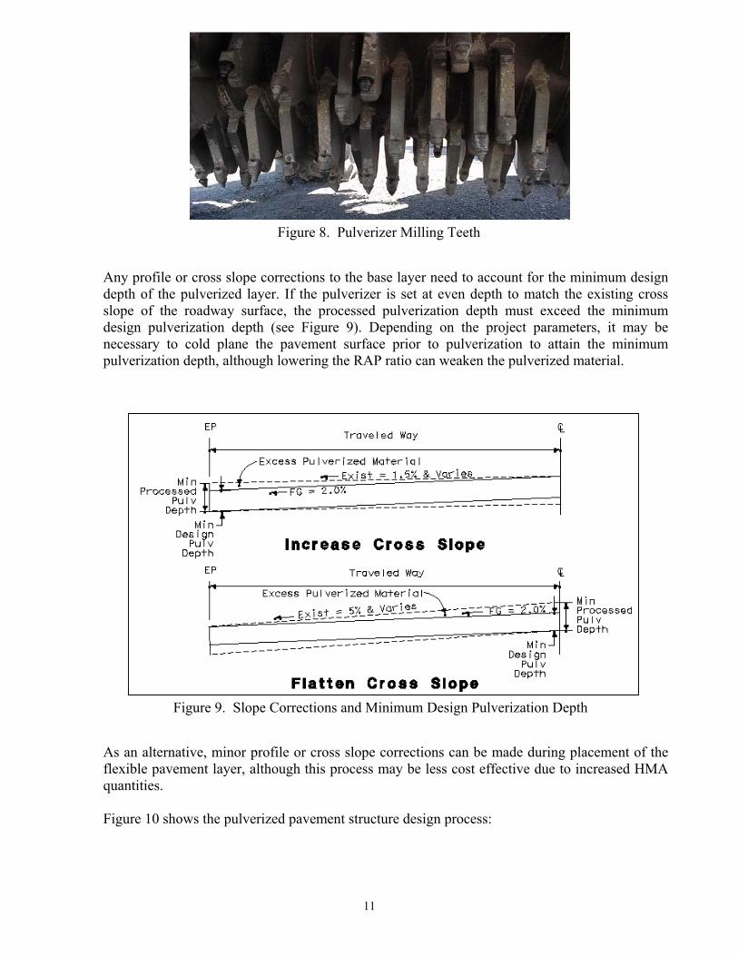
Figure 8. Pulverizer Milling Teeth
Any profile or cross slope corrections to the base layer need to account for the minimum design depth of the pulverized layer. If the pulverizer is set at even depth to match the existing cross slope of the roadway surface, the processed pulverization depth must exceed the minimum design pulverization depth (see Figure 9). Depending on the project parameters, it may be necessary to cold plane the pavement surface prior to pulverization to attain the minimum pulverization depth, although lowering the RAP ratio can weaken the pulverized material.
Figure 9. Slope Corrections and Minimum Design Pulverization Depth
As an alternative, minor profile or cross slope corrections can be made during placement of the flexible pavement layer, although this process may be less cost effective due to increased HMA quantities.
Figure 10 shows the pulverized pavement structure design process:
11
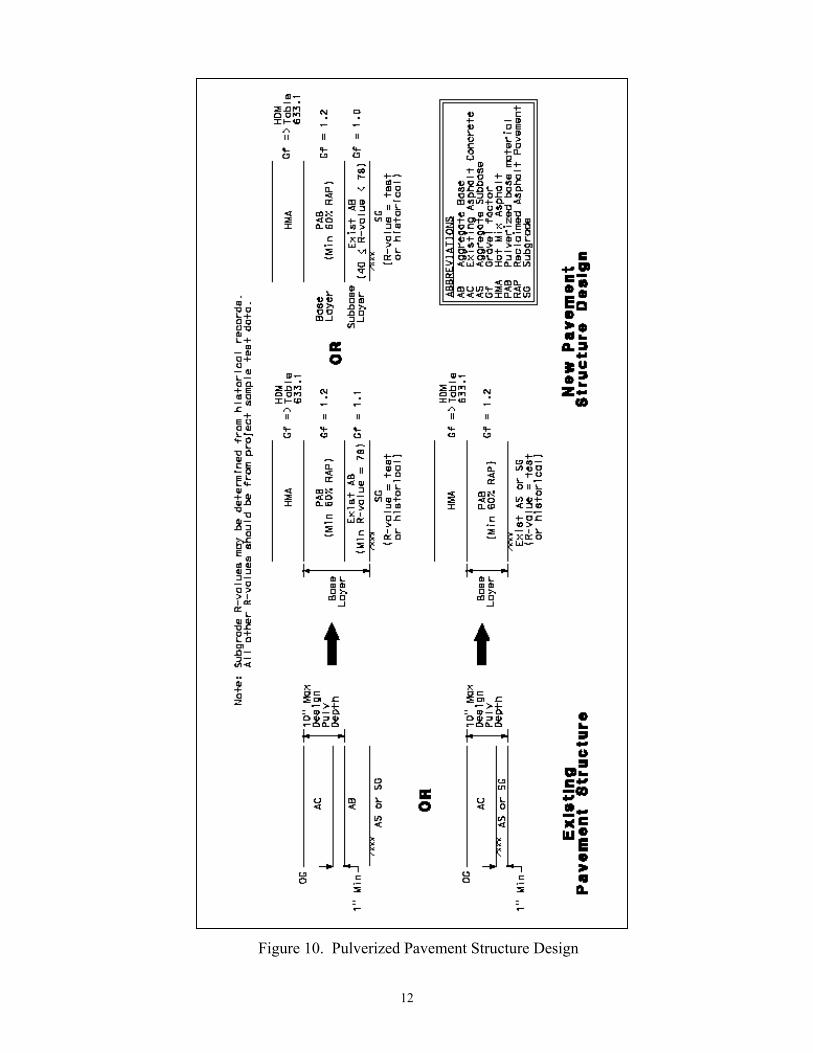
Figure 10. Pulverized Pavement Structure Design
12
5.0 SPECIAL CONSIDERATIONS
5.1 Volumetric Change The pulverization process alters gradation and lowers the density of existing roadway material as it is transformed into compacted pulverized material. Even without adding new material, compacted pulverized material typically swells from 5 to 10% relative to the original material. Excess pulverized material may be used for a thicker base layer, corrections to profile and cross slope, widening sections, or shoulder backing; but excess pulverized material must be accounted for in the project design. If more material is required for the design, supplemental Class 2 AB can be added to the roadway surface immediately prior to pulverization.
5.2 Pulverization Area The width and crown of the roadway to be pulverized dictates the number of passes to cover the full width. Pulverizer milling drums are typically 8 feet wide but can vary in width from 6 to 12 feet. Several passes will normally be required to pulverize the roadway. If the roadway is crowned, the pulverizer should not pass over the crown to ensure uniform treatment depth and consistency in the pulverized material. If the pulverizer does pass over the crown, the processing depth must be increased accordingly so the minimum design depth for the pulverized layer is obtained. Be advised that the strength of the pulverized material is potentially decreased as the ratio of reclaimed asphalt pavement (RAP) to granular base decreases with deeper pulverization. Pulverization should proceed from the outside of the roadway towards the centerline to maintain a reference to the profile elevation. The first pass uses the full width of the pulverizer. In subsequent pulverization passes, the treatment width will be reduced by a minimum overlap of 4 inches. If the treatment depth is more than 12 inches or the pulverized material is coarse, the overlap width should be increased. Other factors to consider are adjacent obstructions such as curb and gutter, concrete barrier, or retaining walls. In the case of curb and gutter, the pulverizer should be able to treat the roadway up to the edge of the gutter. For taller obstructions, the adjacent roadway will have to be removed using another method. The pulverization area should include the entire cross section of the pavement structure from edge of pavement to edge of pavement.
5.3 Pulverized Material Gradation Gradation is controlled by the forward working speed of the pulverizer, milling drum speed, gradation control beam position, mixing chamber front and rear door position, and size of the existing material.(1) When the existing pavement has extensive alligator cracking, the milling drum tends to flip up or lift the flexible layer in large chunks rather than pulverizing the material. If adjustments such as reducing forward speed, increasing milling drum rotational speed, and lowering the rear door are not made, oversized materials can cause problems in the grading and compaction process. The maximum size of the pulverized material will be larger than the maximum size of the original aggregate due to clumping of the RAP. The gradation of the pulverized material should be tested during construction to ensure it corresponds to the gradation required in the special provisions. As shown below in Table 3, the particle distribution should be 100% smaller than 2 inches, 90 to 100% passing the 1½ inch sieve, and no more than 20% passing the No. 200 sieve:
13
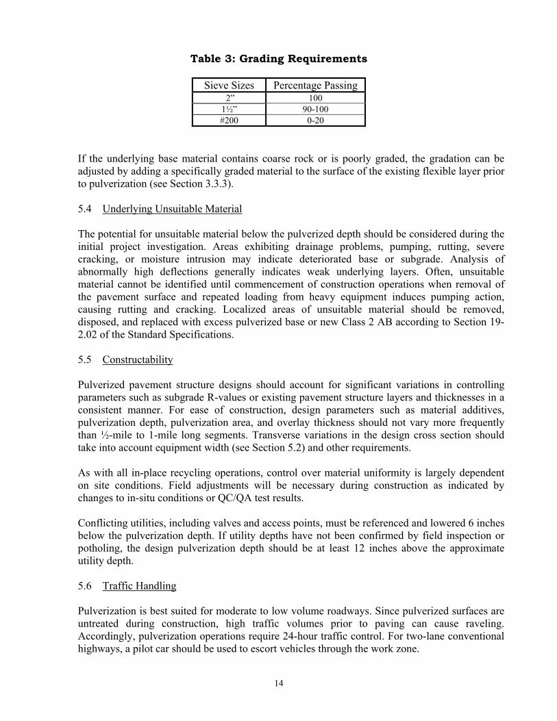
Table 3: Grading Requirements
Sieve Sizes Percentage Passing 2” 100 1½” 90-100 #200 0-20
If the underlying base material contains coarse rock or is poorly graded, the gradation can be adjusted by adding a specifically graded material to the surface of the existing flexible layer prior to pulverization (see Section 3.3.3). 5.4 Underlying Unsuitable Material The potential for unsuitable material below the pulverized depth should be considered during the initial project investigation. Areas exhibiting drainage problems, pumping, rutting, severe cracking, or moisture intrusion may indicate deteriorated base or subgrade. Analysis of abnormally high deflections generally indicates weak underlying layers. Often, unsuitable material cannot be identified until commencement of construction operations when removal of the pavement surface and repeated loading from heavy equipment induces pumping action, causing rutting and cracking. Localized areas of unsuitable material should be removed, disposed, and replaced with excess pulverized base or new Class 2 AB according to Section 19-2.02 of the Standard Specifications. 5.5 Constructability Pulverized pavement structure designs should account for significant variations in controlling parameters such as subgrade R-values or existing pavement structure layers and thicknesses in a consistent manner. For ease of construction, design parameters such as material additives, pulverization depth, pulverization area, and overlay thickness should not vary more frequently than ½-mile to 1-mile long segments. Transverse variations in the design cross section should take into account equipment width (see Section 5.2) and other requirements. As with all in-place recycling operations, control over material uniformity is largely dependent on site conditions. Field adjustments will be necessary during construction as indicated by changes to in-situ conditions or QC/QA test results. Conflicting utilities, including valves and access points, must be referenced and lowered 6 inches below the pulverization depth. If utility depths have not been confirmed by field inspection or potholing, the design pulverization depth should be at least 12 inches above the approximate utility depth.
5.6 Traffic Handling Pulverization is best suited for moderate to low volume roadways. Since pulverized surfaces are untreated during construction, high traffic volumes prior to paving can cause raveling. Accordingly, pulverization operations require 24-hour traffic control. For two-lane conventional highways, a pilot car should be used to escort vehicles through the work zone.
14
If cement is used as an additive, provide a minimum curing period of 1 hour following compaction with no traffic or heavy contractor equipment allowed on the pulverized surface.
6.0 PLANS, SPECIFICATIONS, AND ESTIMATING 6.1 Plans The plans for a pulverization project are analogous to a project using standard roadway rehabilitation strategies. The typical cross sections should clearly show the cross slope, width, and depth of the existing pavement layers, new pulverized base layer, and new flexible pavement layers. The layout plans should show the existing roadway and the limits of pulverization (width and length). Surveyed slope stake information may not be necessary if existing grades are maintained. Any design changes to profile, cross slope, and superelevation should be indicated in the plans so the contractor can account for any additional grading. Areas with and without additives should also be designated. The construction details should include conforming transverse tapers where the pulverized pavement structure ties into existing or new roadway. Quantity sheets should include the stationing and corresponding pulverization areas and additive amounts in the roadway items table. Appendix ‘C’ contains example plan sheets for a pulverization project. 6.2 Specifications A nonstandard special provision for pulverization (NSSP) has been used in District 2, and a standard special provision (SSP) is currently being developed for statewide use. The specification will address a number of items, including material and equipment requirements, construction methods, inspection, quality control and quality assurance (QC/QA), acceptance requirements, measurement, and payment. Until the SSP is finalized, prior approval from the Chief of the Office of Flexible Pavement Materials in the Division of Materials Engineering and Testing Services (METS) is required to use pulverization on Caltrans projects. 6.3 Estimating The estimation process for pulverization cost must take into account several project specific features: project location, length, schedule, geometrics, and traffic handling, as well as pulverization depth and area, are primary factors. Typical project mobilization costs for pulverization equipment run under $10,000, keeping the process cost effective for smaller projects and areas. Historical cost data for District 2 pulverization projects is available on the intranet from the North Region Unit Cost Database (see Appendix D). Among other considerations, analysis of historical costs must consider that past pulverization projects were located in a single district and used an NSSP that quantified unit cost by station.
6.3.1 Measurement and Payment
The item “Pulverize Roadbed” is measured and paid for by the square yard based on the theoretical pulverization area and includes all labor, materials, tools, equipment, and testing related to the pulverization operation and preparation of the existing roadway. The roadbed dimensions to be pulverized should be shown on the typical sections, layout plans, and quantity sheets to clearly indicate the limits of the pulverized roadbed (See Appendix C).
15
Additional additives such as Class 2 AB, lime, and cement are measured and paid for per ton. The item includes all labor, materials, tools, equipment, and incidentals for placing and mixing the additive with the pulverized roadbed. No cost adjustment is made for increases or decreases in additive quantities during construction operations unless the pulverization dimensions are changed. Section 4-1.03B, “Increased or Decreased Quantities,” of the Standard Specifications does not apply. 6.3.2 Supplemental Work
Due to the difficulty in identifying underlying unsuitable material (see Section 5.4), a Supplemental Work item for roadway excavation to remove and dispose of the material should be included in the estimate if unsuitable material has been identified or is otherwise likely to be present on a project. Any unsuitable material that has already been identified should be quantified and estimated as a roadway item and not included in Supplemental Work.
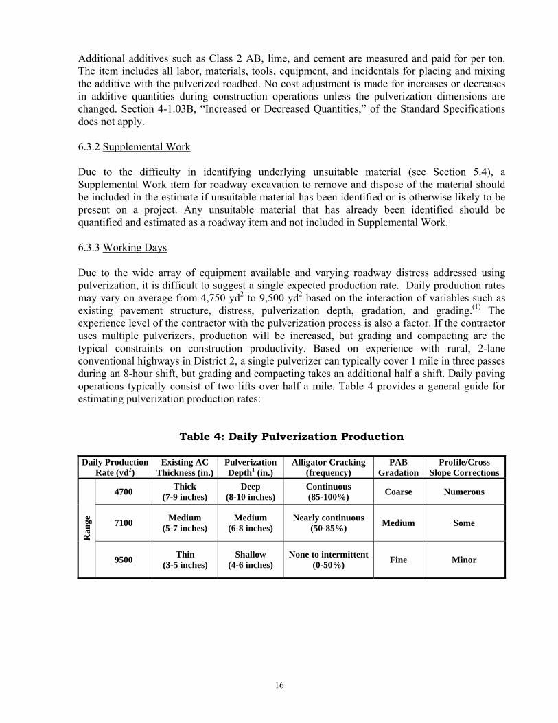
6.3.3 Working Days Due to the wide array of equipment available and varying roadway distress addressed using pulverization, it is difficult to suggest a single expected production rate. Daily production rates may vary on average from 4,750 yd2 to 9,500 yd2 based on the interaction of variables such as existing pavement structure, distress, pulverization depth, gradation, and grading.(1) The experience level of the contractor with the pulverization process is also a factor. If the contractor uses multiple pulverizers, production will be increased, but grading and compacting are the typical constraints on construction productivity. Based on experience with rural, 2-lane conventional highways in District 2, a single pulverizer can typically cover 1 mile in three passes during an 8-hour shift, but grading and compacting takes an additional half a shift. Daily paving operations typically consist of two lifts over half a mile. Table 4 provides a general guide for estimating pulverization production rates:
Table 4: Daily Pulverization Production Daily Production
Rate (yd2) Existing AC
Thickness (in.) Pulverization Depth1 (in.)
Alligator Cracking (frequency)
PAB Gradation
Profile/Cross Slope Corrections
4700 Thick (7-9 inches)
Deep (8-10 inches)
Continuous (85-100%) Coarse Numerous
7100 Medium (5-7 inches)
Medium (6-8 inches)
Nearly continuous (50-85%) Medium Some
Ran
ge
9500 Thin (3-5 inches)
Shallow (4-6 inches)
None to intermittent (0-50%) Fine Minor
16

7.0 REFERENCES:
1. Asphalt Recycling and Reclaiming Association, “Basic Asphalt Recycling Manual” – 2001.
2. David Jones and John Harvey – “Relationship between DCP, Stiffness, Shear Strength, and
R-value” – July 2005.
3. Manuel Bejarano and Bruce Steven – “Effects of Different Compaction Efforts on Virgin and Recycled Granular Materials for Roads” – September 2006.
4. Manuel Bejarano – “Evaluation of Recycled Asphalt Concrete Materials as Aggregate Base”
– November 2001.
5. Joint Departments of the Army and Air Force, USA, TM 5-822-14/AFMAN 32-8010, “Soil Stabilization for Pavements” – 25 October 1994.
6. Bruce Steven, Eungjin Jeon, and John T. Harvey – “Initial Recommendation of a Gravel
Factor for Pulverized Asphalt Concrete Used as an Unbound Base” – April 2007.
17
APPENDIX A
I
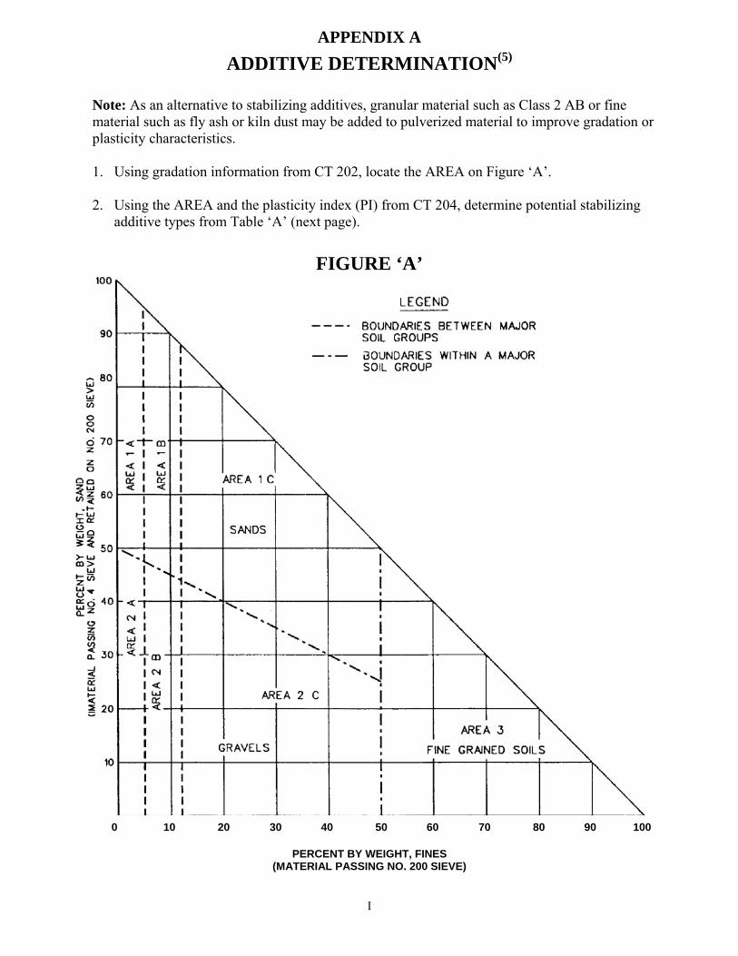
ADDITIVE DETERMINATION(5)
Note: As an alternative to stabilizing additives, granular material such as Class 2 AB or fine material such as fly ash or kiln dust may be added to pulverized material to improve gradation or plasticity characteristics. 1. Using gradation information from CT 202, locate the AREA on Figure ‘A’.
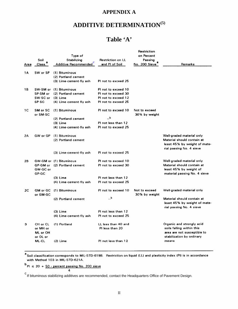
2. Using the AREA and the plasticity index (PI) from CT 204, determine potential stabilizing
additive types from Table ‘A’ (next page).
FIGURE ‘A’
0 10 20 30 40 50 60 70 80 90 100
PERCENT BY WEIGHT, FINES (MATERIAL PASSING NO. 200 SIEVE)
APPENDIX A
ADDITIVE DETERMINATION(5)
Table ‘A’
c
c If bituminous stabilizing additives are recommended, contact the Headquarters Office of Pavement Design.
II
APPENDIX B
III
EXAMPLE PULVERIZED PAVMENT STRUCTURE
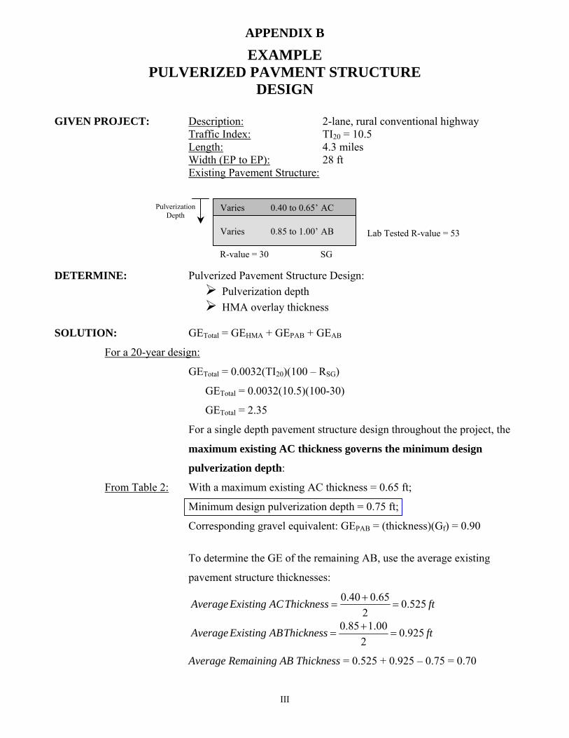
DESIGN GIVEN PROJECT: Description: 2-lane, rural conventional highway Traffic Index: TI20 = 10.5 Length: 4.3 miles Width (EP to EP): 28 ft Existing Pavement Structure: DETERMINE: Pulverized Pavement Structure Design:
Pulverization depth HMA overlay thickness
SOLUTION: GETotal = GEHMA + GEPAB + GEAB
For a 20-year design:
GETotal = 0.0032(TI20)(100 – RSG)
GETotal = 0.0032(10.5)(100-30)
GETotal = 2.35
For a single depth pavement structure design throughout the project, the
maximum existing AC thickness governs the minimum design
pulverization depth:
From Table 2: With a maximum existing AC thickness = 0.65 ft;
Minimum design pulverization depth = 0.75 ft;
Corresponding gravel equivalent: GEPAB = (thickness)(Gf) = 0.90
To determine the GE of the remaining AB, use the average existing
pavement structure thicknesses:
ftThicknessACExistingAverage 525.02
65.040.0=
+=
ftThicknessABExistingAverage 925.02
00.185.0=
+=
Average Remaining AB Thickness = 0.525 + 0.925 – 0.75 = 0.70
Varies 0.85 to 1.00’ AB
R-value = 30 SG
Lab Tested R-value = 53
Pulverization Depth
Varies 0.40 to 0.65’ AC
APPENDIX B
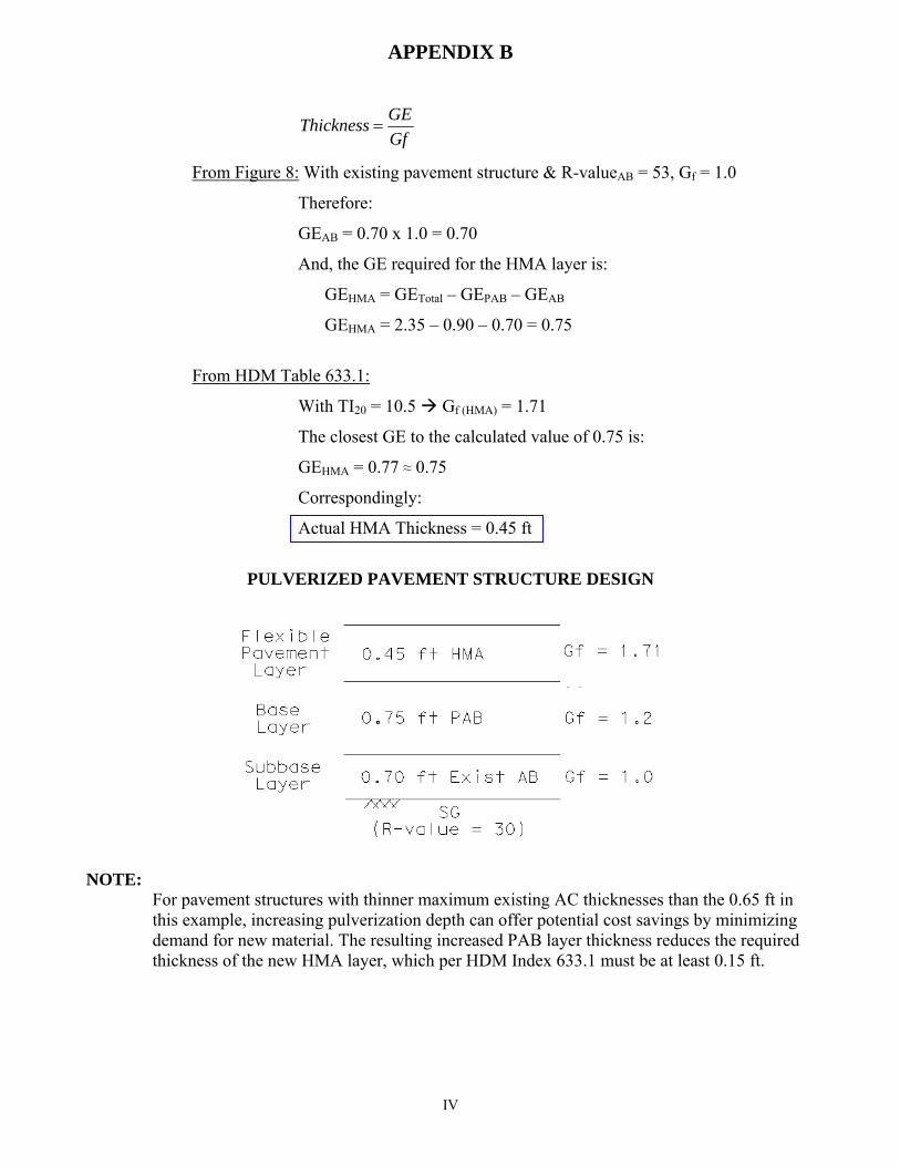
GfGEThickness =
From Figure 8: With existing pavement structure & R-valueAB = 53, Gf = 1.0
Therefore:
GEAB = 0.70 x 1.0 = 0.70
And, the GE required for the HMA layer is:
GEHMA = GETotal – GEPAB – GEAB
GEHMA = 2.35 – 0.90 – 0.70 = 0.75
From HDM Table 633.1:
With TI20 = 10.5 Gf (HMA) = 1.71
The closest GE to the calculated value of 0.75 is:
GEHMA = 0.77 ≈ 0.75
Correspondingly:
Actual HMA Thickness = 0.45 ft
PULVERIZED PAVEMENT STRUCTURE DESIGN
NOTE: For pavement structures with thinner maximum existing AC thicknesses than the 0.65 ft in this example, increasing pulverization depth can offer potential cost savings by minimizing demand for new material. The resulting increased PAB layer thickness reduces the required thickness of the new HMA layer, which per HDM Index 633.1 must be at least 0.15 ft.
IV
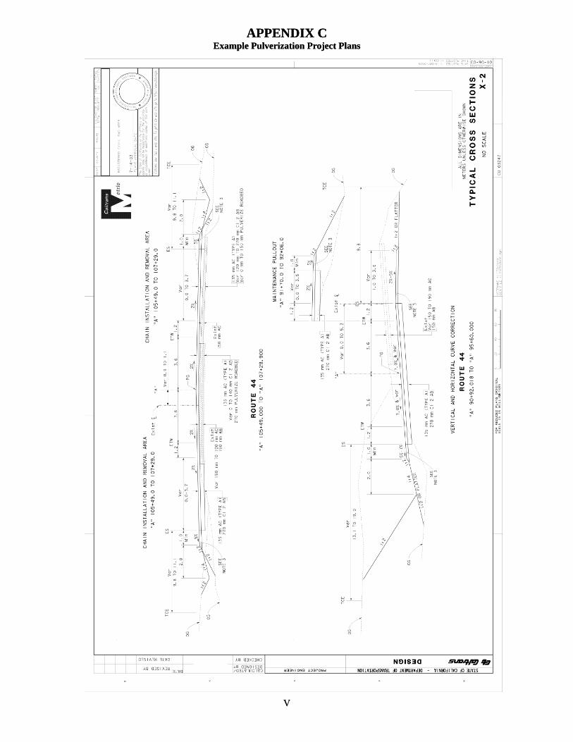
APPENDIX C Example Pulverization Project Plans
V
APPENDIX C Example Pulverization Project Plans
V
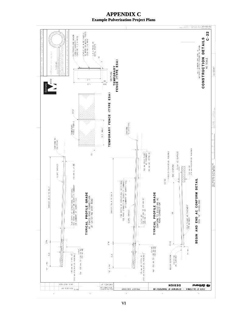
APPENDIX C Example Pulverization Project Plans
APPENDIX C Example Pulverization Project Plans
VI
VI
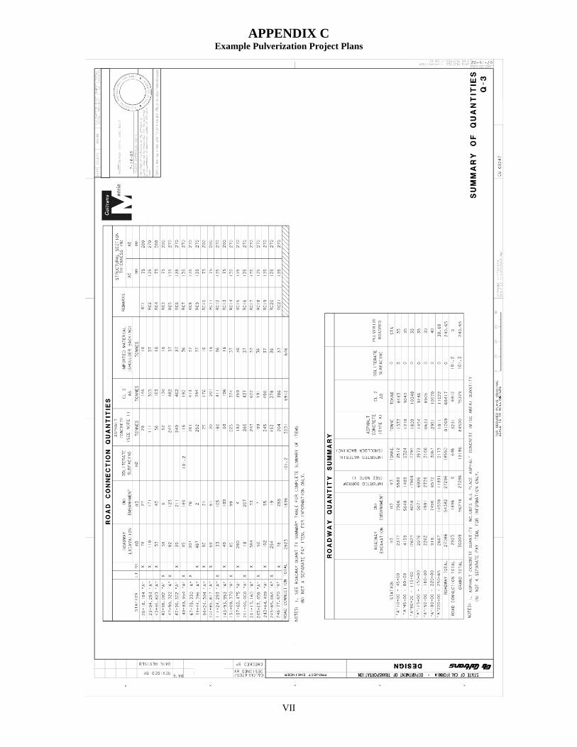
APPENDIX C Example Pulverization Project Plans
VII
APPENDIX D
VIII
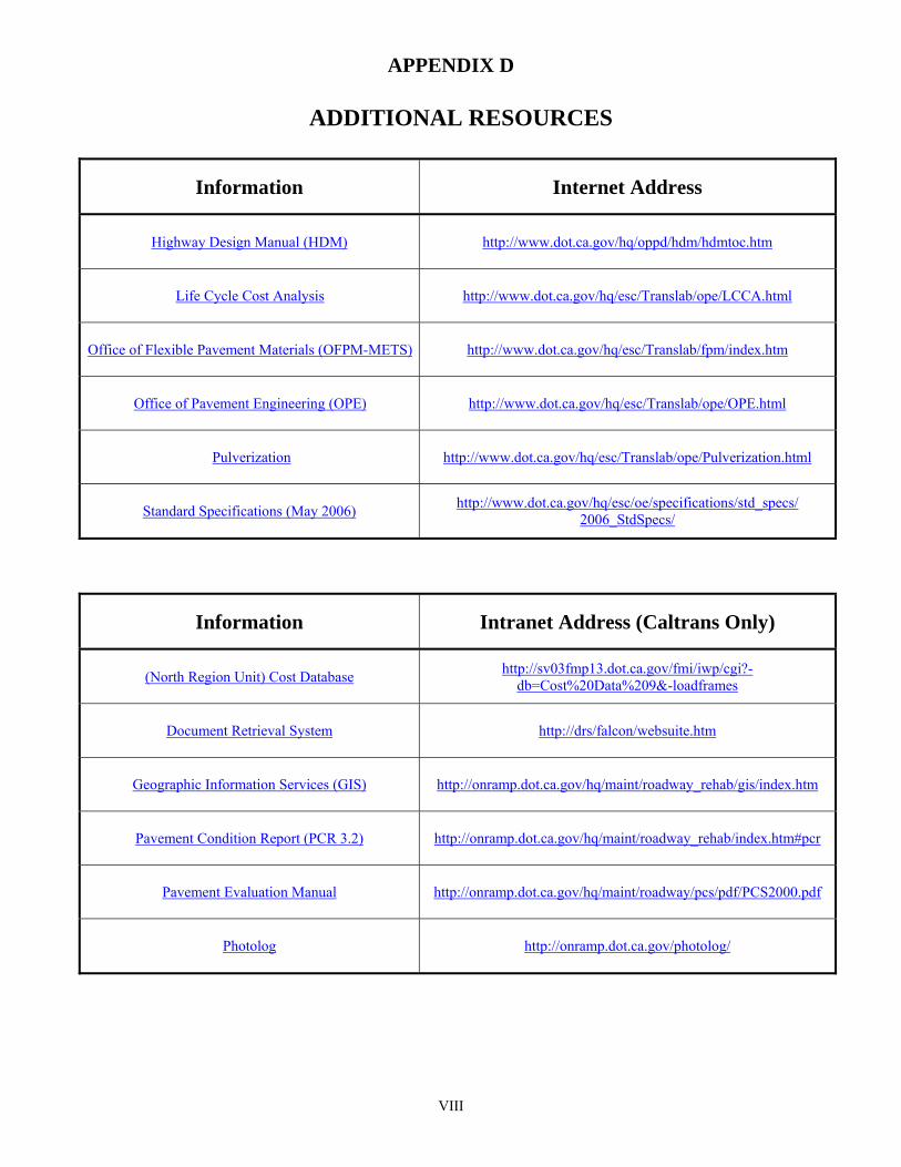
ADDITIONAL RESOURCES
Information Internet Address
Highway Design Manual (HDM)
http://www.dot.ca.gov/hq/oppd/hdm/hdmtoc.htm
Life Cycle Cost Analysis http://www.dot.ca.gov/hq/esc/Translab/ope/LCCA.html
Office of Flexible Pavement Materials (OFPM-METS)
http://www.dot.ca.gov/hq/esc/Translab/fpm/index.htm
Office of Pavement Engineering (OPE)
http://www.dot.ca.gov/hq/esc/Translab/ope/OPE.html
Pulverization
http://www.dot.ca.gov/hq/esc/Translab/ope/Pulverization.html
Standard Specifications (May 2006)
http://www.dot.ca.gov/hq/esc/oe/specifications/std_specs/ 2006_StdSpecs/
Information Intranet Address (Caltrans Only)
(North Region Unit) Cost Database
http://sv03fmp13.dot.ca.gov/fmi/iwp/cgi?-db=Cost%20Data%209&-loadframes
Document Retrieval System
http://drs/falcon/websuite.htm
Geographic Information Services (GIS)
http://onramp.dot.ca.gov/hq/maint/roadway_rehab/gis/index.htm
Pavement Condition Report (PCR 3.2)
http://onramp.dot.ca.gov/hq/maint/roadway_rehab/index.htm#pcr
Pavement Evaluation Manual
http://onramp.dot.ca.gov/hq/maint/roadway/pcs/pdf/PCS2000.pdf
Photolog
http://onramp.dot.ca.gov/photolog/