橋 地下鉄長堀鶴見緑地線 ド JR東西線 1 西口 ク‚¯ 松下IMPホール ツイン21アトリウム ツイン21MIDタワー 会議室(4階・20階) 松下IMPビル
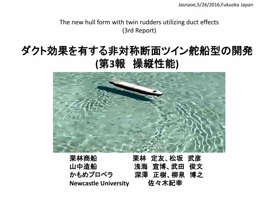
ダクト効果を有する非対称断面ツイン舵船型の開発 (第3報 操縦性能)
栗林商船 栗林 定友、松坂 武彦 山中造船 浅海 宣博、武田 俊文 かもめプロペラ 深澤 正樹、柳泉 博之 Newcastle University 佐々木紀幸
The new hull form with twin rudders utilizing duct effects (3rd Report)
Jasnaoe,5/26/2016,Fukuoka Japan
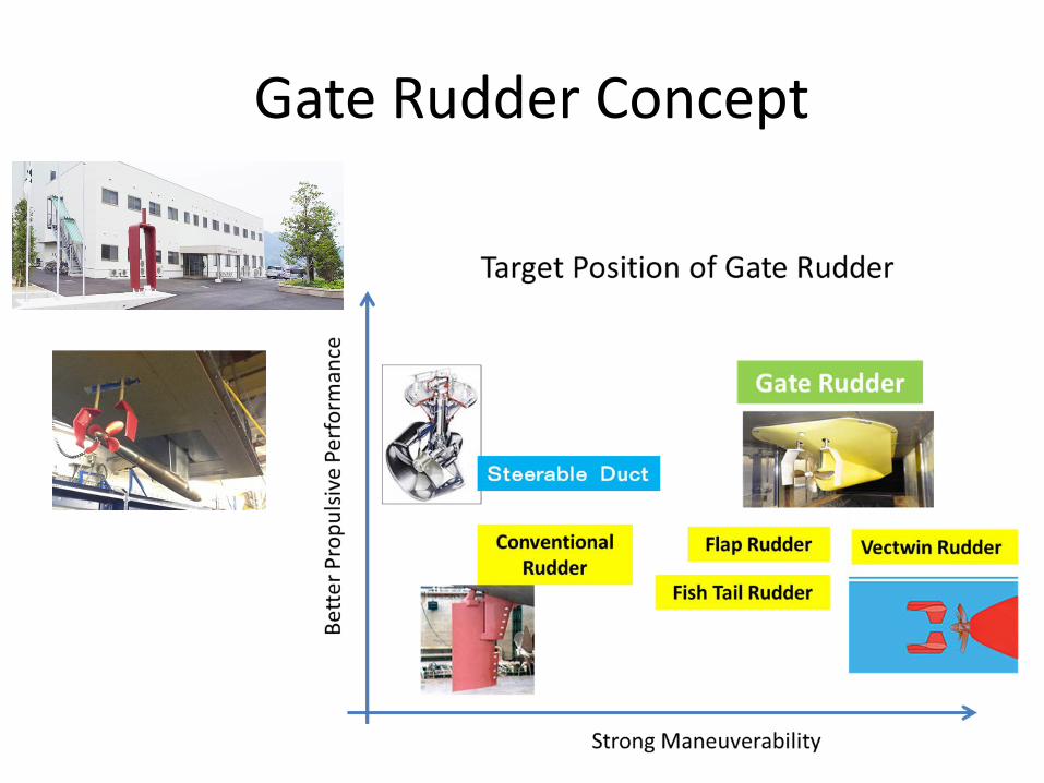
Gate Rudder Concept
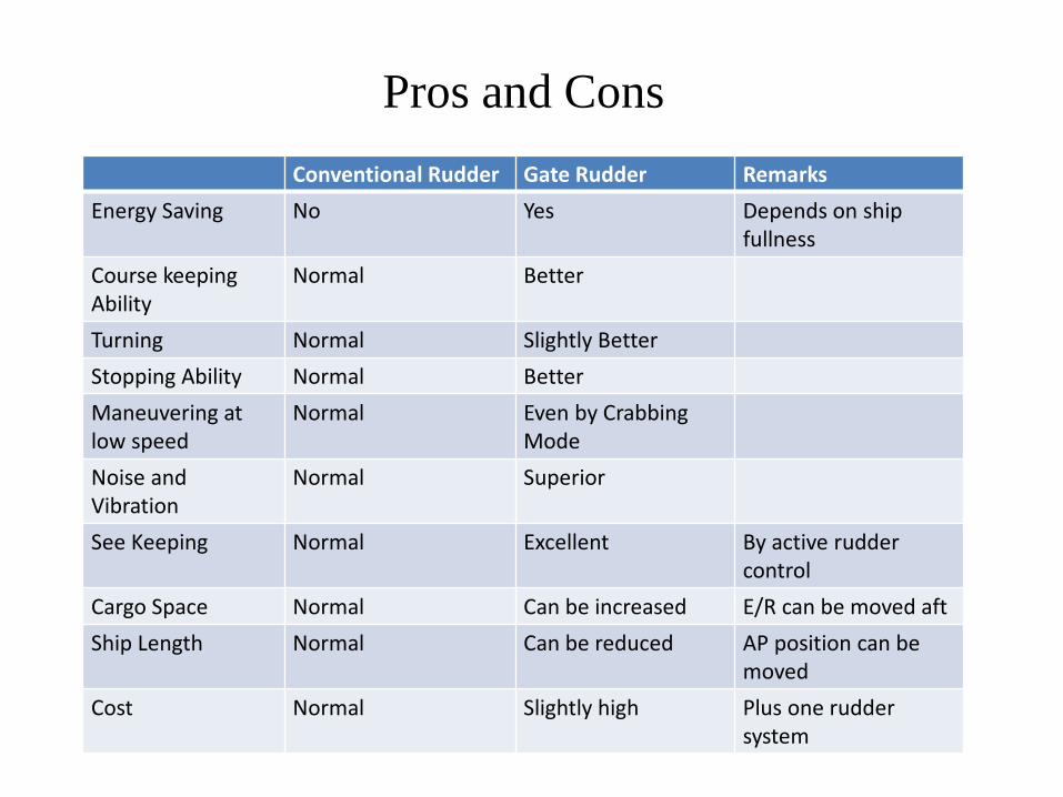
Pros and Cons Conventional Rudder Gate Rudder Remarks
Energy Saving No Yes Depends on ship fullness
Course keeping Ability
Normal Better
Turning Normal Slightly Better Stopping Ability Normal Better Maneuvering at low speed
Normal Even by Crabbing Mode
Noise and Vibration
Normal Superior
See Keeping Normal Excellent By active rudder control
Cargo Space Normal Can be increased E/R can be moved aft Ship Length Normal Can be reduced AP position can be
moved Cost Normal Slightly high Plus one rudder
system
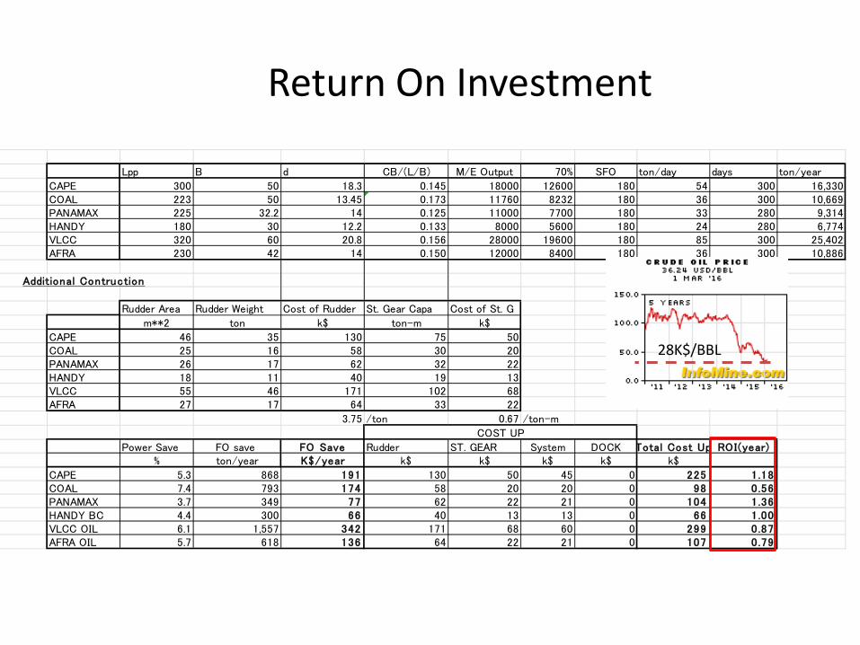
Lpp B d CB/(L/B) M/E Output 70% SFO ton/day days ton/year
CAPE 300 50 18.3 0.145 18000 12600 180 54 300 16,330COAL 223 50 13.45 0.173 11760 8232 180 36 300 10,669PANAMAX 225 32.2 14 0.125 11000 7700 180 33 280 9,314HANDY 180 30 12.2 0.133 8000 5600 180 24 280 6,774VLCC 320 60 20.8 0.156 28000 19600 180 85 300 25,402AFRA 230 42 14 0.150 12000 8400 180 36 300 10,886
Additional Contruction
Rudder Area Rudder Weight Cost of Rudder St. Gear Capa Cost of St. G
m**2 ton k$ ton-m k$
CAPE 46 35 130 75 50COAL 25 16 58 30 20PANAMAX 26 17 62 32 22HANDY 18 11 40 19 13VLCC 55 46 171 102 68AFRA 27 17 64 33 22
3.75 /ton 0.67 /ton-m
Power Save FO save FO Save Rudder ST. GEAR System DOCK Total Cost Up ROI(year)% ton/year K$/year k$ k$ k$ k$ k$
CAPE 5.3 868 191 130 50 45 0 225 1.18COAL 7.4 793 174 58 20 20 0 98 0.56PANAMAX 3.7 349 77 62 22 21 0 104 1.36HANDY BC 4.4 300 66 40 13 13 0 66 1.00VLCC OIL 6.1 1,557 342 171 68 60 0 299 0.87AFRA OIL 5.7 618 136 64 22 21 0 107 0.79
COST UP
28K$/BBL
Return On Investment
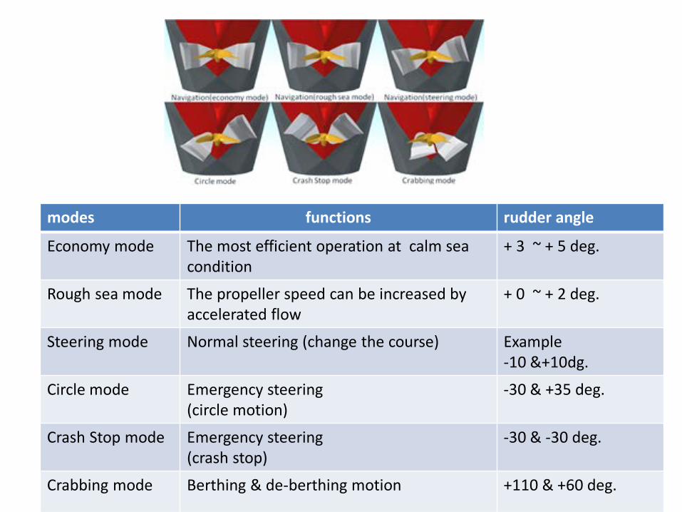
modes functions rudder angle
Economy mode The most efficient operation at calm sea condition
+ 3 ~ + 5 deg.
Rough sea mode The propeller speed can be increased by accelerated flow
+ 0 ~ + 2 deg.
Steering mode Normal steering (change the course) Example -10 &+10dg.
Circle mode Emergency steering (circle motion)
-30 & +35 deg.
Crash Stop mode Emergency steering (crash stop)
-30 & -30 deg.
Crabbing mode Berthing & de-berthing motion +110 & +60 deg.
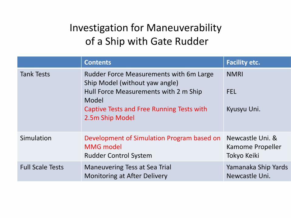
Investigation for Maneuverability of a Ship with Gate Rudder
Contents Facility etc.
Tank Tests Rudder Force Measurements with 6m Large Ship Model (without yaw angle) Hull Force Measurements with 2 m Ship Model Captive Tests and Free Running Tests with 2.5m Ship Model
NMRI FEL Kyusyu Uni.
Simulation Development of Simulation Program based on MMG model Rudder Control System
Newcastle Uni. & Kamome Propeller Tokyo Keiki
Full Scale Tests Maneuvering Tess at Sea Trial Monitoring at After Delivery
Yamanaka Ship Yards Newcastle Uni.
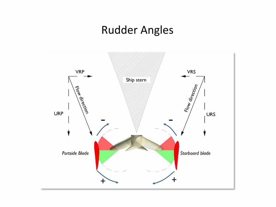
Rudder Angles
- -
+ +
)2()cos()1(
)1(5.0 2
L
L
δρ
HNR
RY
aFYdLU
YC
+=
=
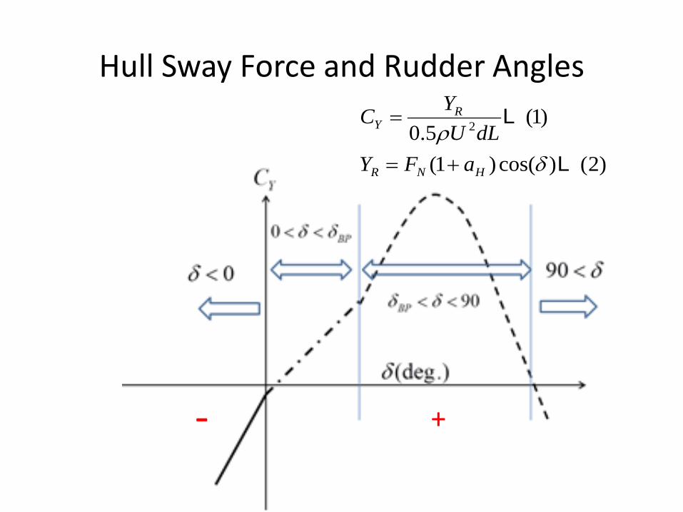
Hull Sway Force and Rudder Angles
- +

0<δ<δBP:後方への小舵角の操舵であり、プロペラ後流の外に舵が存在する δBP<δ<90:後方への大舵角で、プロペラ後の影響を受ける領域
)3()sin(21
12 LRRN AfUF δρ=
)4()sin(21
22 LRRN AfUF δρ=
)5()sin()(21
242
132 Lδρ RPRRN AfUAfUF +=
δ<0:前方に操舵した場合で船体との干渉が最も大きい領域
90<δ:舵の後縁がプロペラに近づき、流れが後縁から前縁へと向かう領域
)6()sin(21
52 Lδρ RPN AfUF =
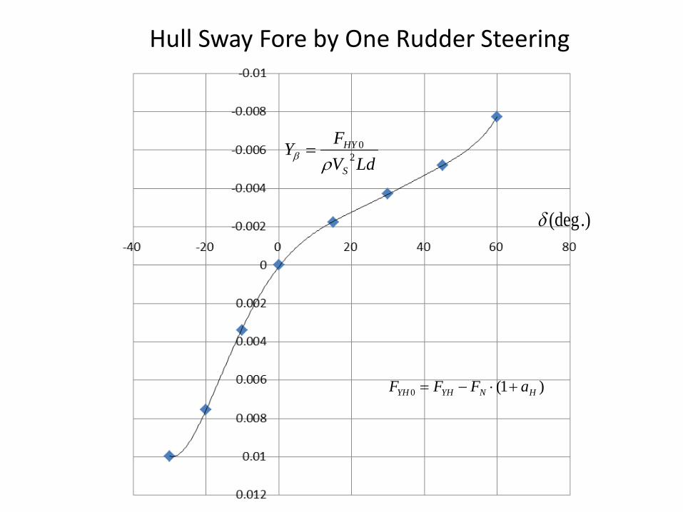
Hull Sway Fore by One Rudder Steering
LdVFY
S
HY2
0
ρβ =
.)(degδ
)1(0 HNYHYH aFFF +⋅−=

Hull Sway Force by Two Rudders Steering
LdVFY
S
HY2
0
ρβ =
.)(degδ
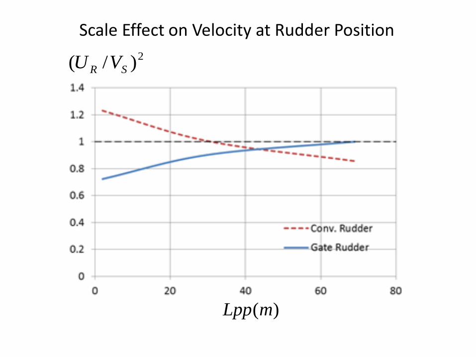
)(mLpp
2)/( SR VU
Scale Effect on Velocity at Rudder Position

Fy by Two Rudders Steering (corrected for Scale Effect)
Gate rudder
Conventional Rudder (Fish Tail)
LdVFY
S
HY2
0
ρβ =
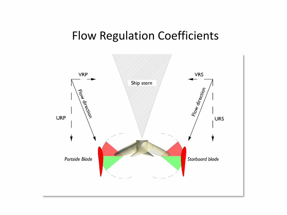
Flow Regulation Coefficients
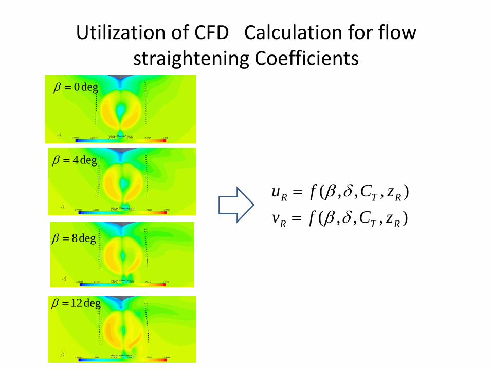
Utilization of CFD Calculation for flow straightening Coefficients
deg0=β
deg4=β
deg8=β
deg12=β
),,,(),,,(
RTR
RTR
zCfvzCfu
δβδβ
==
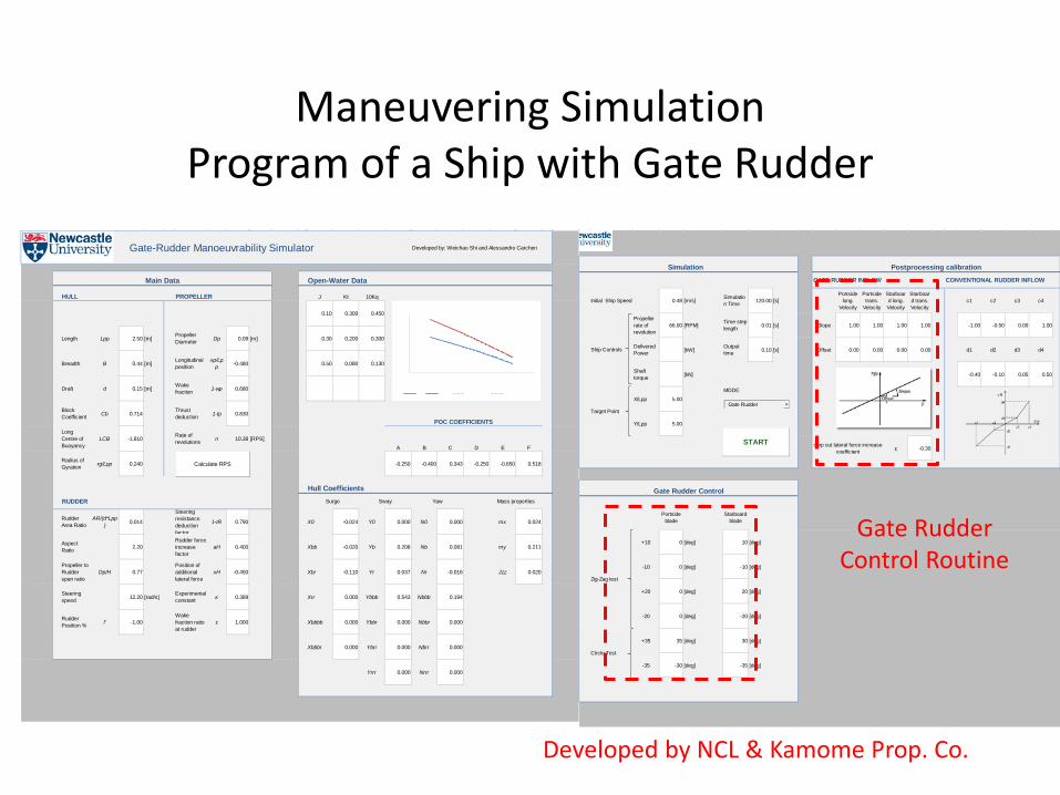
Maneuvering Simulation Program of a Ship with Gate Rudder
Gate-Rudder Manoeuvrability Simulator Developed by: Weichao Shi and Alessandro Carchen
Open-Water Data
HULL PROPELLER J Kt 10Kq
0.10 0.300 0.450
Length Lpp 2.50 [m] PropellerDiameter Dp 0.09 [m] 0.30 0.200 0.300
Breadth B 0.44 [m] Longitudinalposition
xp/Lpp -0.480 0.50 0.080 0.130
Draft d 0.15 [m] Wakefraction 1-wp 0.680
BlockCoefficient Cb 0.714 Thrust
deduction 1-tp 0.830
LongCentre ofBuoyancy
LCB -1.810 Rate ofrevolutions n 10.38 [RPS]
A B C D E F
Radius ofGyration rg/Lpp 0.240 -0.250 -0.400 0.343 -0.250 -0.650 0.518
Hull CoefficientsRUDDER
RudderArea Ratio
AR/(d*Lpp) 0.014
Steeringresistancedeductionfactor
1-tR 0.790 X0 -0.024 Y0 0.000 N0 0.000 mx 0.024
AspectRatio 2.20
Rudder forceincreasefactor
aH 0.400 Xbb -0.020 Yb 0.208 Nb 0.081 my 0.211
Propeller toRudderspan ratio
Dp/H 0.77Position ofadditionallateral force
xH -0.450 Xbr -0.110 Yr 0.037 Nr -0.016 Jzz 0.020
Steeringspeed 12.20 [rad/s] Experimental
constant κ 0.389 Xrr 0.000 Ybbb 0.543 Nbbb 0.194
RudderPosition % l' -1.00
Wakefraction ratioat rudder
ε 1.000 Xbbbb 0.000 Ybbr 0.000 Nbbr 0.000
Xbbbr 0.000 Ybrr 0.000 Nbrr 0.000
Yrrr 0.000 Nrrr 0.000
Main Data
POC COEFFICIENTS
Surge Sway Yaw Mass properties
Calculate RPS
GATE RUDDER INFLOW CONVENTIONAL RUDDER INFLOW
Initial Ship Speed 0.48 [m/s] Simulation Time 120.00 [s]
Portsidelong.
Velocity
Portsidetrans.
Velocity
Starboard long.Velocity
Starboard trans.Velocity
c1 c2 c3 c4
Propellerrate ofrevolution
66.00 [RPM] Time steplength 0.01 [s] Slope 1.00 1.00 1.00 1.00 -1.00 -0.50 0.00 1.00
DeliveredPower [kW] Output
time 0.10 [s] Offset 0.00 0.00 0.00 0.00 d1 d2 d3 d4
Shafttorque [kN] -0.40 -0.10 0.05 0.50
X/Lpp 5.00MODE
Y/Lpp 5.00
χ -0.30
Portsideblade
Starboardblade
+10 0 [deg] 10 [deg]
-10 0 [deg] -10 [deg]
+20 0 [deg] 20 [deg]
-20 0 [deg] -20 [deg]
+35 35 [deg] 30 [deg]
-35 -30 [deg] -35 [deg]
Gate Rudder Control
Circle Test
Zig-Zag test
step out lateral force increasecoefficient
Simulation
Ship Controls
Target Point
Postprocessing calibration
START
Gate Rudder
Gate Rudder Control Routine
Developed by NCL & Kamome Prop. Co.

Model Basin of Kyusyu University
船舶運動性能試験水槽は,水槽本体と模型曳引車,プランジャー型造波装置によって構成されています。水槽本体は長さ38.8m,幅24.4m,水深2mです。水槽底部を高精度で平坦に仕上げたことにより,世界的にも数
少ない浅水域を対象とした浮体運動の実験が実施可能な水槽となっています。

2.5 m model equipped with gate rudder and measurement instrument s
Gate Rudder Propeller
Steering Device
Load Cell

Captive Model Tests
FHY
FHX
MHZ
FRY
MRZ
FRX
FPX MPX
β
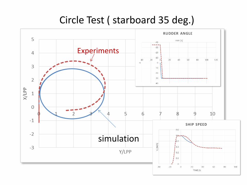
Circle Test ( starboard 35 deg.)
simulation
Experiments
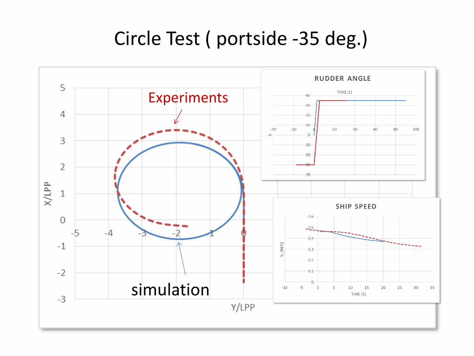
Circle Test ( portside -35 deg.)
simulation
Experiments
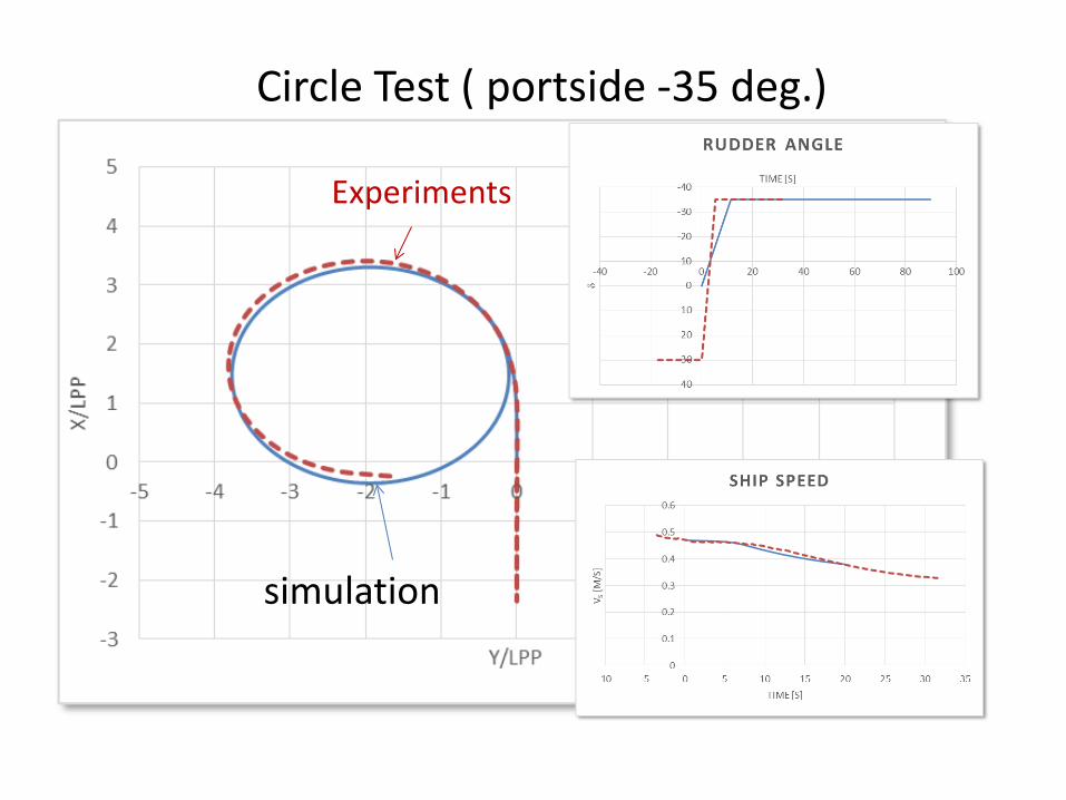
Circle Test ( portside -35 deg.)
simulation
Experiments
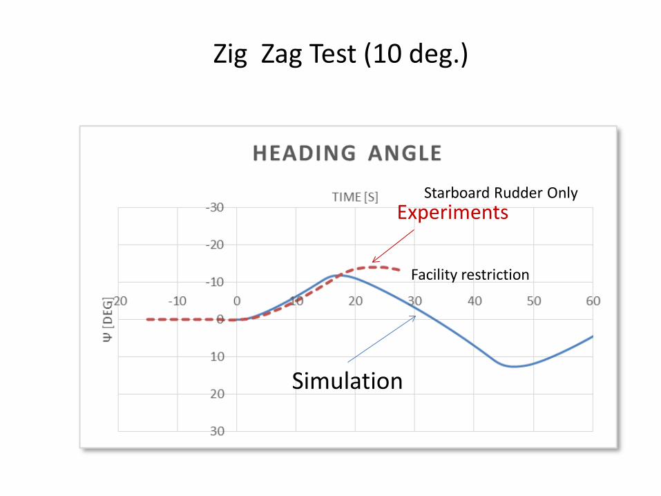
Zig Zag Test (10 deg.)
Simulation
Experiments Starboard Rudder Only
Facility restriction
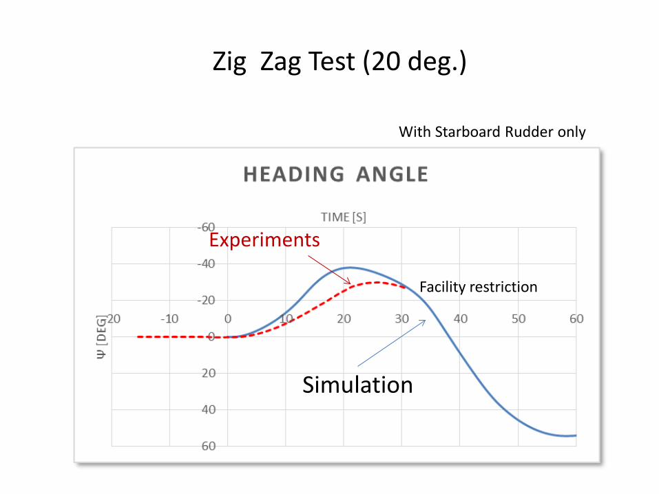
Zig Zag Test (20 deg.)
With Starboard Rudder only
Simulation
Experiments
Facility restriction
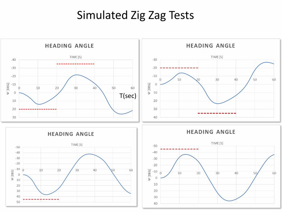
Simulated Zig Zag Tests
T(sec)
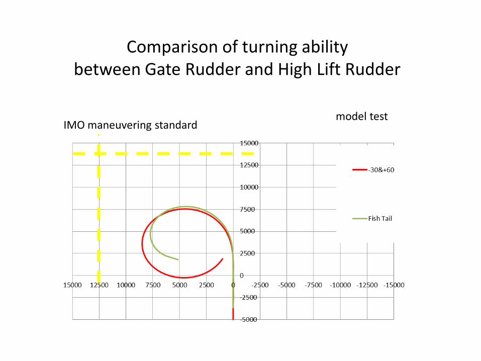
Comparison of turning ability between Gate Rudder and High Lift Rudder
model test IMO maneuvering standard
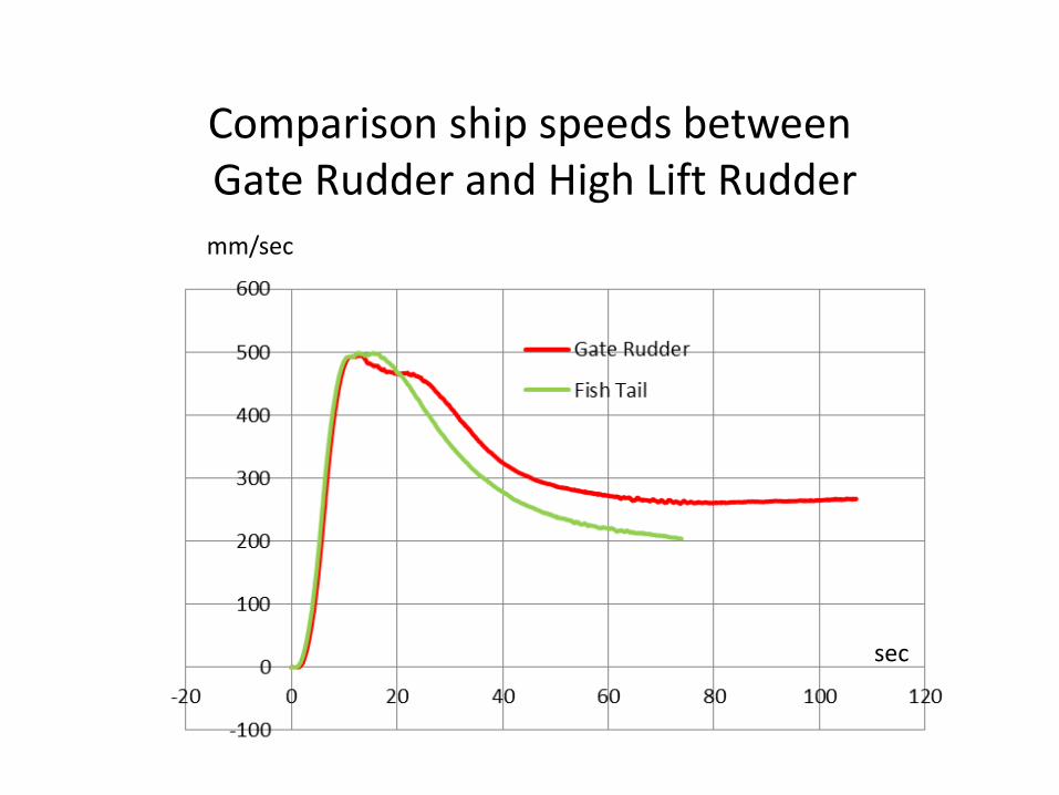
Comparison ship speeds between Gate Rudder and High Lift Rudder mm/sec
sec
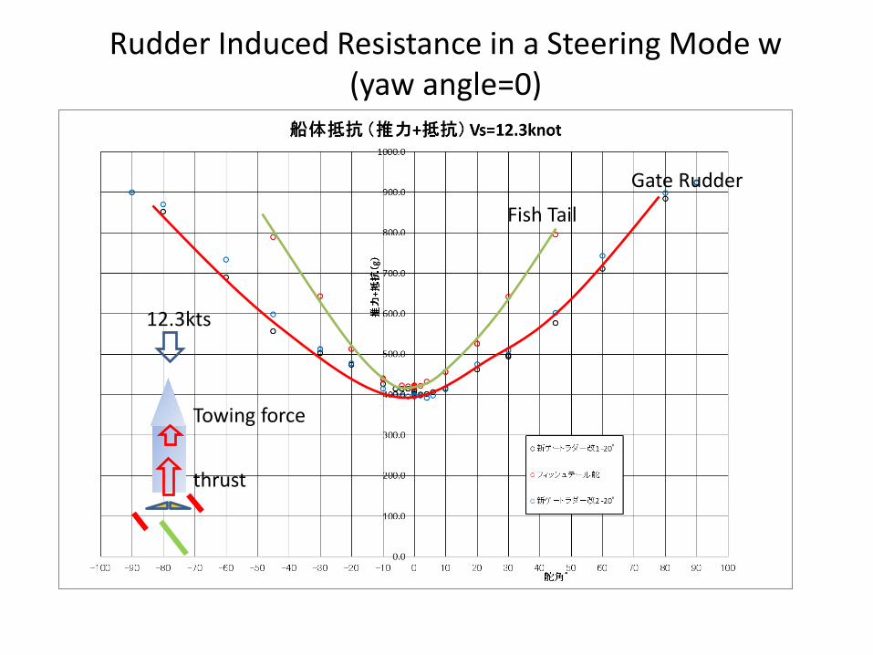
Rudder Induced Resistance in a Steering Mode w (yaw angle=0)
Fish Tail Gate Rudder
12.3kts
thrust
Towing force
結論
(1)ゲートラダーを搭載予定の499内航船の操縦性能 を模型試験と操縦性のシミュレーションプログラム により調査した (2)施設や計測装置の制約があり、一部、確認できない 操縦性能があったが、シミュレーションにより確認 ができた。 (3)ゲートラダーは、操舵角が大きいこともあり、従来舵 断面を用いても高揚力舵と同等または同等以上の 操舵力を発揮できる。 (4)ゲート舵は、操舵時の舵抵抗が小さく、航海中の微 小操舵による馬力増加の減少が期待できること、 また、海象悪化時の操船能力が高い可能性がある ことが分かった。
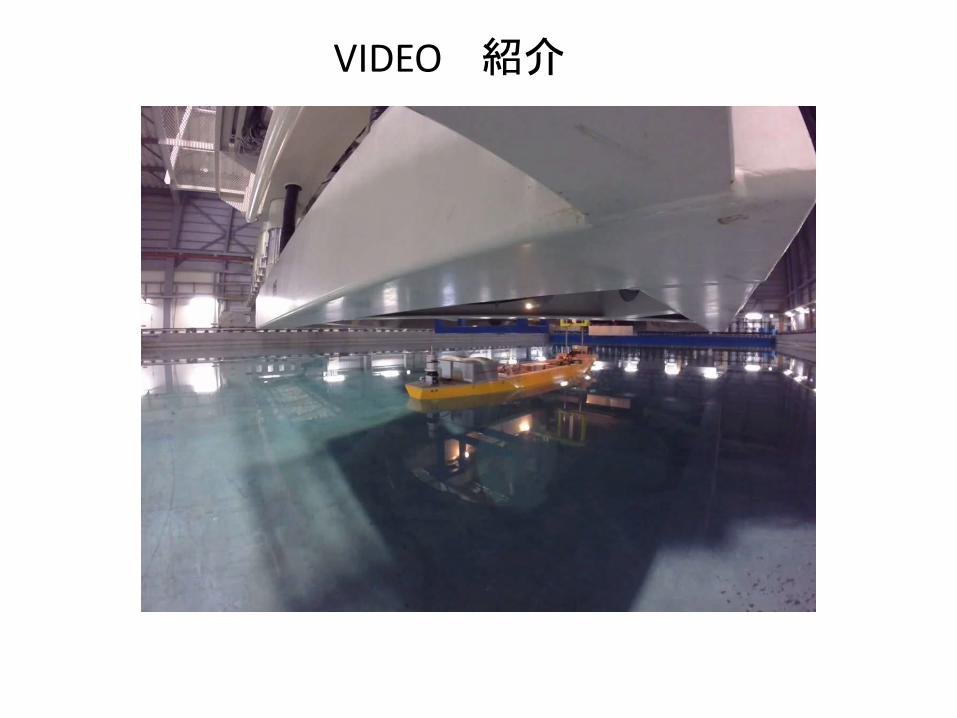
VIDEO 紹介