Eurocode 7 – Eurocode 7 – fundamental issues and some implications for users BP198.2 BP201.2 •...
124
1 Nordic Geotechnical Meeting Copenhagen, May 2012 BP198.1 BP201.1 Eurocode 7 – fundamental issues and some implications for users Brian Simpson, Arup Geotechnics
Transcript of Eurocode 7 – Eurocode 7 – fundamental issues and some implications for users BP198.2 BP201.2 •...

1
Nordic Geotechnical MeetingCopenhagen, May 2012 BP198.1
BP201.1
Eurocode 7 –fundamental issues and some implications for users
Brian Simpson, Arup Geotechnics
2
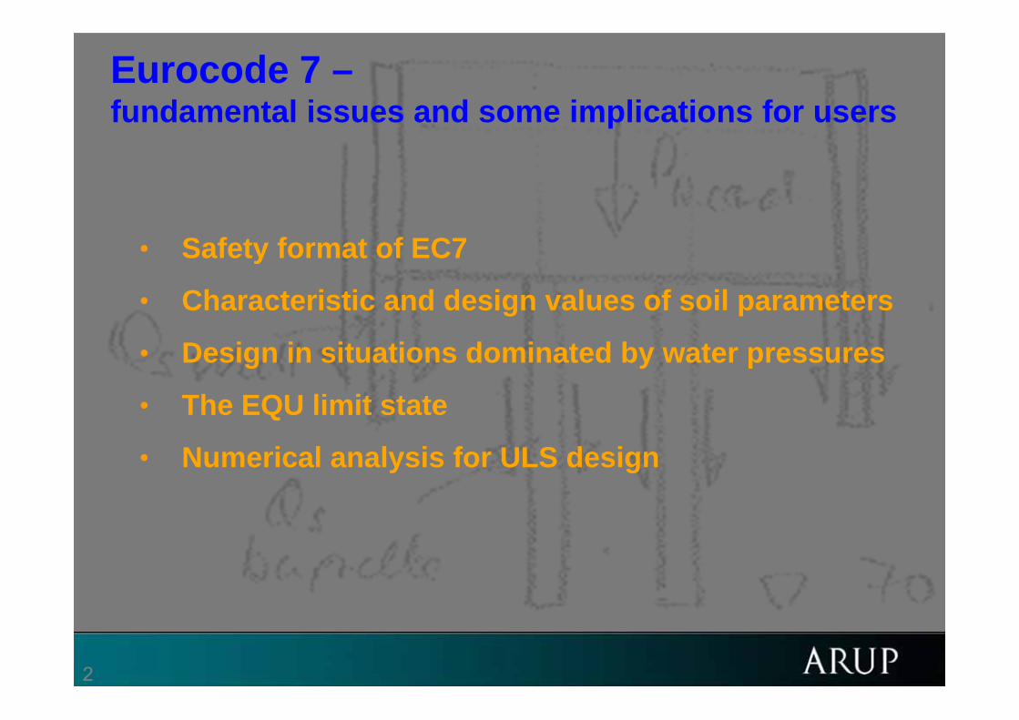
Eurocode 7 –fundamental issues and some implications for users
BP198.2 BP201.2
• Safety format of EC7
• Characteristic and design values of soil parameters
• Design in situations dominated by water pressures
• The EQU limit state
• Numerical analysis for ULS design
3
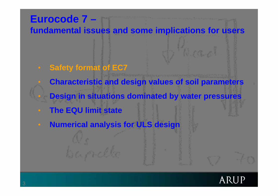
Eurocode 7 –fundamental issues and some implications for users
BP198.2 BP201.2
• Safety format of EC7
• Characteristic and design values of soil parameters
• Design in situations dominated by water pressures
• The EQU limit state
• Numerical analysis for ULS design
4
EN1990 Ultimate limit states BP87.48 BP106.14 BP111.8 BP112.10 BP124-T1.41 BP168.28 BP188.6 BP190a.20
BP198.7
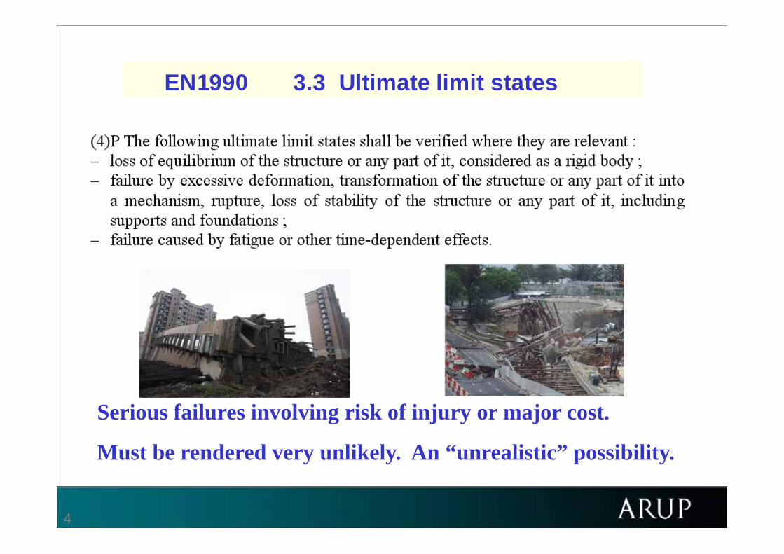
EN1990 3.3 Ultimate limit states
Serious failures involving risk of injury or major cost.
Must be rendered very unlikely. An “unrealistic” possibility.

5
EN1990 Serviceability limit states BP87.49 BP106.15 BP111.9 BP112.11 BP124-T1.42 BP168.29
Inconveniences, disappointments and more manageable costs.
Should be rare, but it might be uneconomic to eliminate them completely.
EN1990 3.4 Serviceability limit states
66
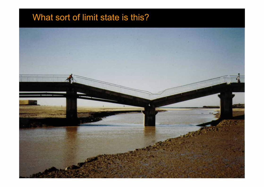
What sort of limit state is this?BP190a.28
7
2.4.7 Ultimate Limit States BP124-T1.92
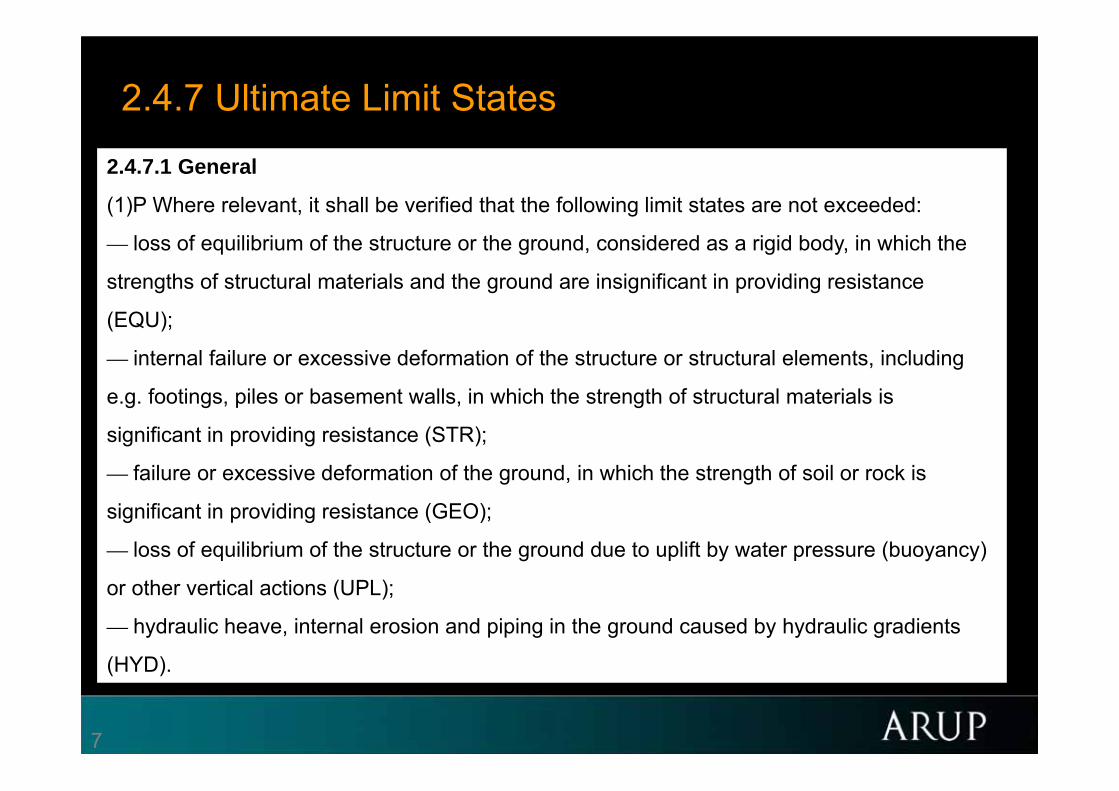
2.4.7.1 General
(1)P Where relevant, it shall be verified that the following limit states are not exceeded:
— loss of equilibrium of the structure or the ground, considered as a rigid body, in which the
strengths of structural materials and the ground are insignificant in providing resistance
(EQU);
— internal failure or excessive deformation of the structure or structural elements, including
e.g. footings, piles or basement walls, in which the strength of structural materials is
significant in providing resistance (STR);
— failure or excessive deformation of the ground, in which the strength of soil or rock is
significant in providing resistance (GEO);
— loss of equilibrium of the structure or the ground due to uplift by water pressure (buoyancy)
or other vertical actions (UPL);
— hydraulic heave, internal erosion and piping in the ground caused by hydraulic gradients
(HYD).
8
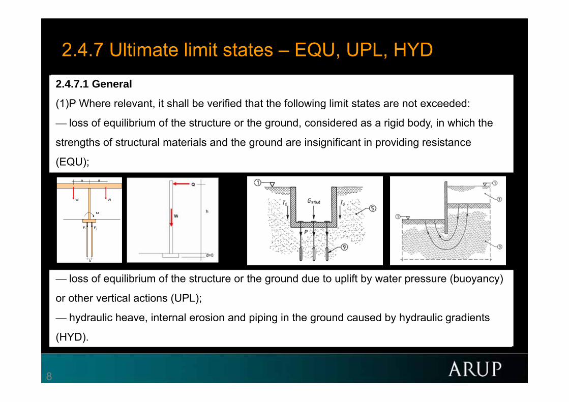
2.4.7 Ultimate limit states – EQU, UPL, HYD
2.4.7.1 General
(1)P Where relevant, it shall be verified that the following limit states are not exceeded:
— loss of equilibrium of the structure or the ground, considered as a rigid body, in which the
strengths of structural materials and the ground are insignificant in providing resistance
(EQU);
— internal failure or excessive deformation of the structure or structural elements, including
e.g. footings, piles or basement walls, in which the strength of structural materials is
significant in providing resistance (STR);
— failure or excessive deformation of the ground, in which the strength of soil or rock is
significant in providing resistance (GEO);
— loss of equilibrium of the structure or the ground due to uplift by water pressure (buoyancy)
or other vertical actions (UPL);
— hydraulic heave, internal erosion and piping in the ground caused by hydraulic gradients
(HYD).
a a
W W
M
F1 F2
b

9
2.4.7 Ultimate limit states – STR, GEO
10
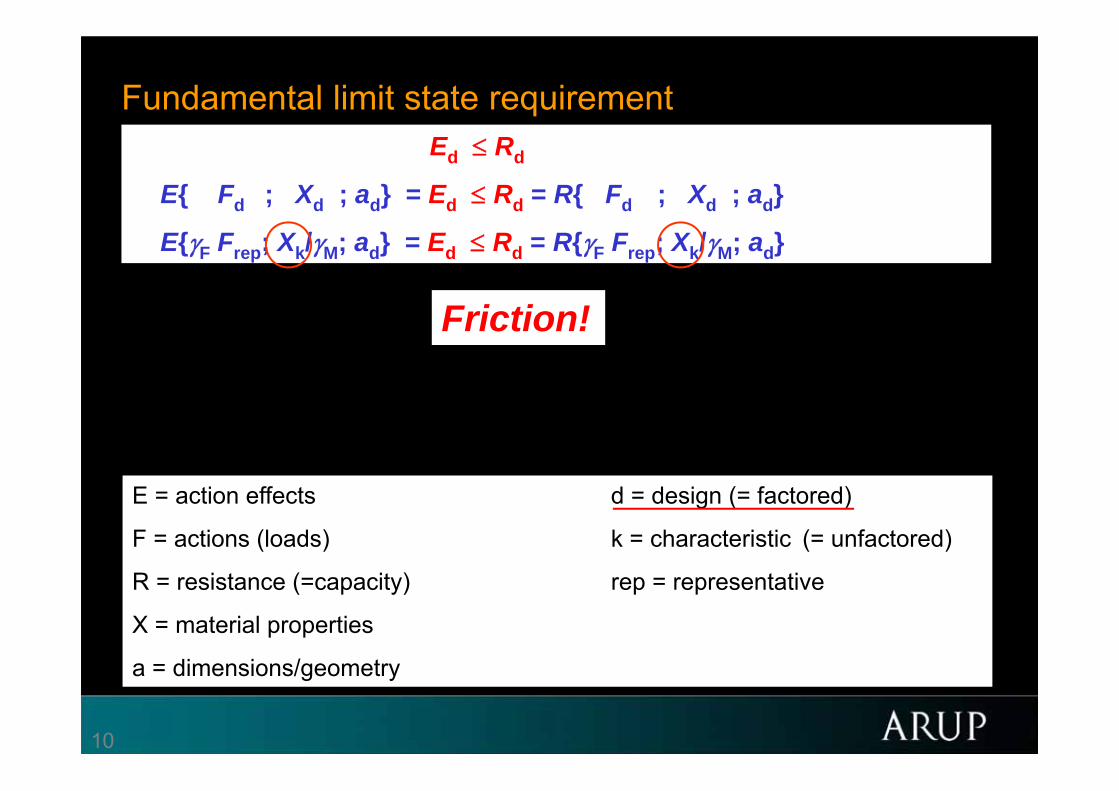
Fundamental limit state requirementEd Rd
E{ Fd ; Xd ; ad} = Ed Rd = R{ Fd ; Xd ; ad}
E{F Frep; Xk/M; ad} = Ed Rd = R{F Frep; Xk/M; ad}
E = action effects d = design (= factored)
F = actions (loads) k = characteristic (= unfactored)
R = resistance (=capacity) rep = representative
X = material properties
a = dimensions/geometry
Friction!
11
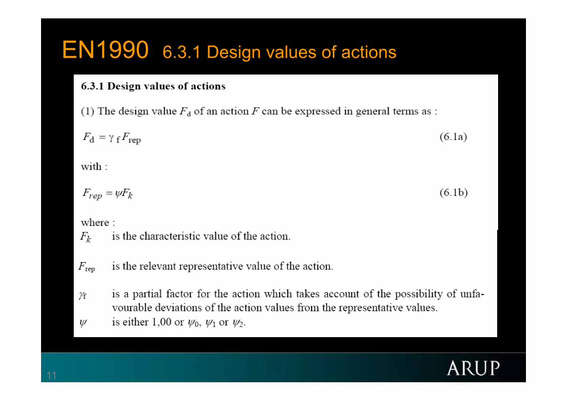
EN1990 6.3.1 Design values of actions
12
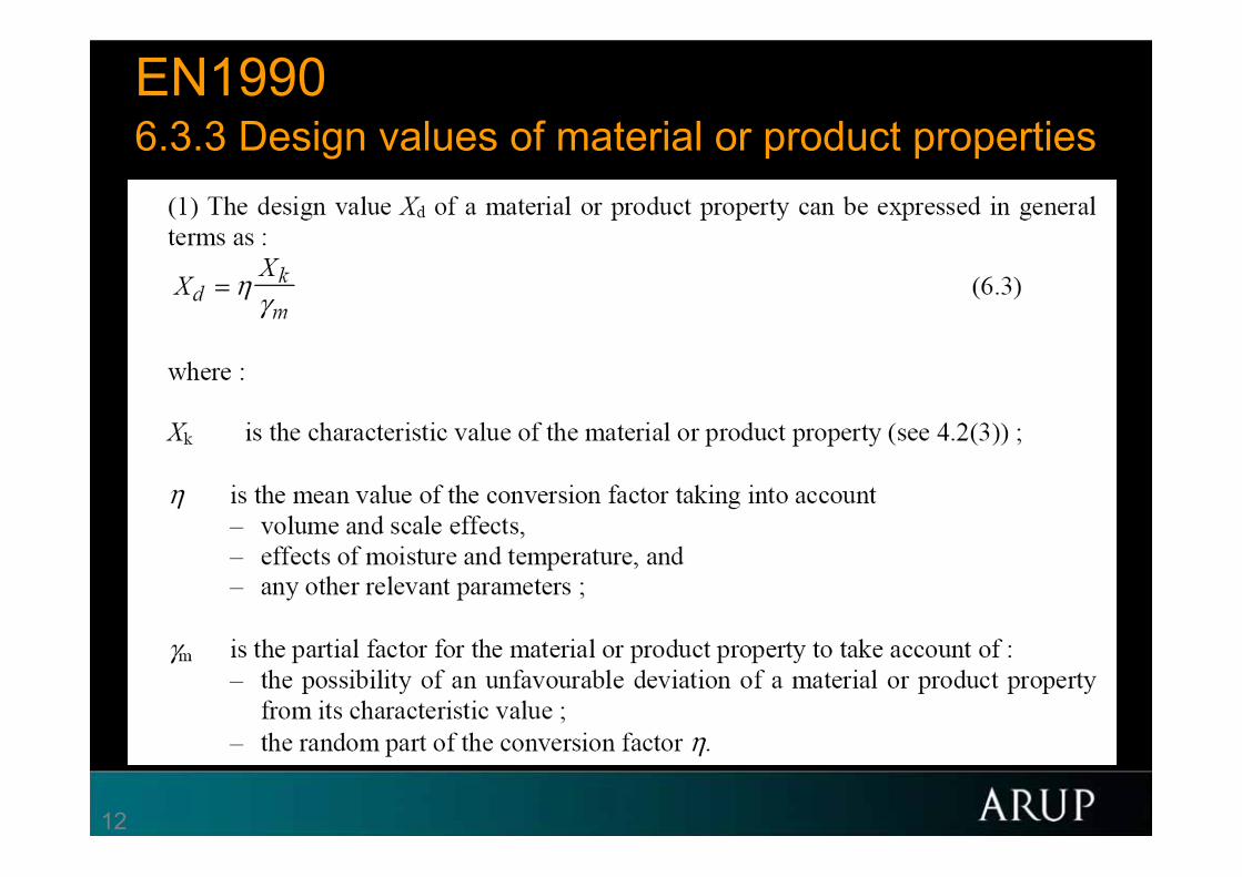
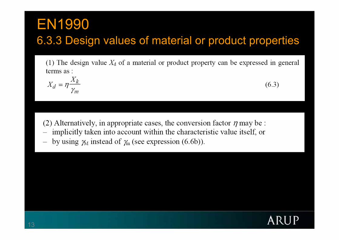
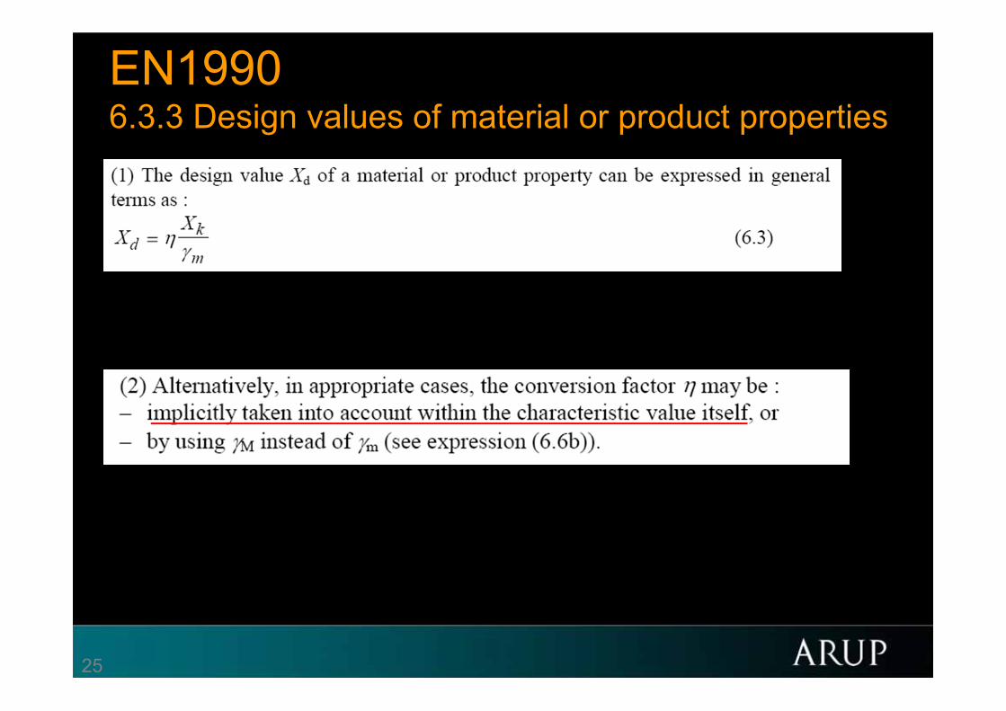
EN19906.3.3 Design values of material or product properties
13
EN19906.3.3 Design values of material or product properties

14
Fundamental limit state requirementEd Rd
E{ Fd ; Xd ; ad} = Ed Rd = R{ Fd ; Xd ; ad}
E{F Frep; Xk/M; ad} = Ed Rd = R{F Frep; Xk/M; ad}
or E{F Frep; Xk/M; ad} = Ed Rd = Rk/R = RnR (LRFD)
or E Ek = Ed Rd = Rk/R
so in total
E E{F Frep; Xk/M; ad} = Ed Rd = R{F Frep; Xk/M; ad}/R
E = action effects d = design (= factored)
F = actions (loads) k = characteristic (= unfactored)
R = resistance (=capacity) rep = representative
X = material properties
a = dimensions/geometry

15
EC7 2.4.7 Ultimate Limit States2.4.7.3 Verification of resistance for structural and ground limit states in persistent and
transient situations
2.4.7.3.1 General
(1)P When considering a limit state of rupture or excessive deformation of a structural element or section of the ground (STR and GEO), it shall be verified that:
Ed Rd (2.5)
2.4.7.3.2 Design effects of actions
(1) Partial factors on actions may be applied either to the actions themselves (Frep) or to their effects (E):
Ed = E{F Frep; Xk/M; ad} (2.6a)
or
Ed = E E{Frep; Xk/M; ad}. (2.6b)
16
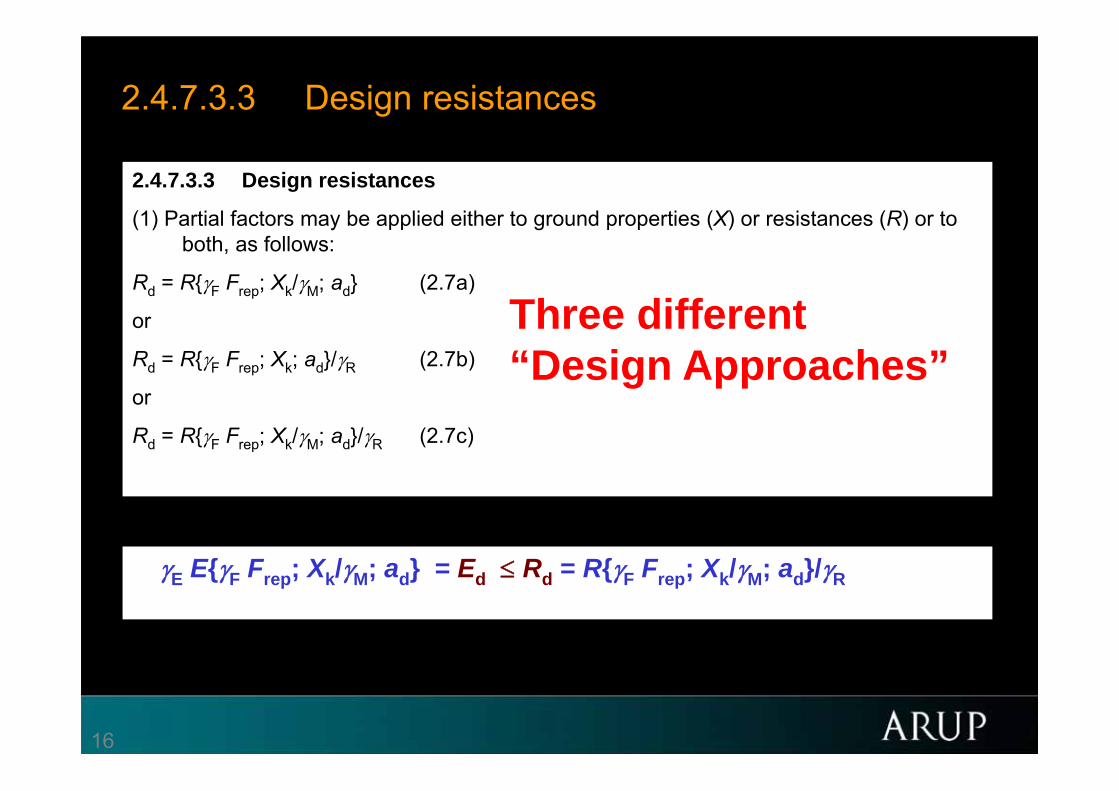
2.4.7.3.3 Design resistances
2.4.7.3.3 Design resistances
(1) Partial factors may be applied either to ground properties (X) or resistances (R) or to both, as follows:
Rd = R{F Frep; Xk/M; ad} (2.7a)
or
Rd = R{F Frep; Xk; ad}/R (2.7b)
or
Rd = R{F Frep; Xk/M; ad}/R (2.7c)
E E{F Frep; Xk/M; ad} = Ed Rd = R{F Frep; Xk/M; ad}/R
Three different “Design Approaches”

17
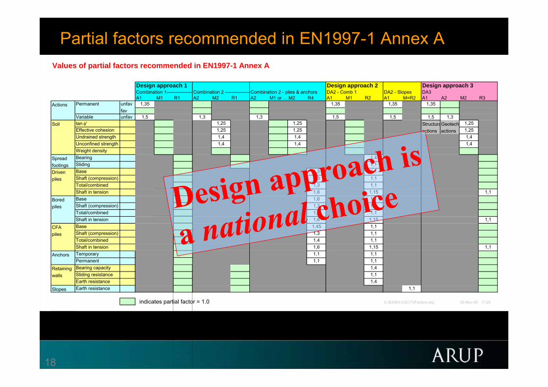
Partial factors recommended in EN1997-1 Annex A BP111.19 BP124-T2.14 BP124-A2.12 BP168.81 BP188.34Values of partial factors recommended in EN1997-1 Annex A
Design approach 1 Design approach 2 Design approach 3Combination 1---------------- Combination 2 ----------------Combination 2 - piles & anchors DA2 - Comb 1 DA2 - Slopes DA3A1 M1 R1 A2 M2 R1 A2 M1 or … M2 R4 A1 M1 R2 A1 M=R2 A1 A2 M2 R3
Actions unfav 1,35 1,35 1,35 1,35favunfav 1,5 1,3 1,3 1,5 1,5 1,5 1,3
Soil tan ' 1,25 1,25 StructuraGeotech 1,25Effective cohesion 1,25 1,25 actions actions 1,25Undrained strength 1,4 1,4 1,4Unconfined strength 1,4 1,4 1,4Weight density
Spread Bearing 1,4footings Sliding 1,1Driven Base 1,3 1,1piles Shaft (compression) 1,3 1,1
Total/combined 1,3 1,1Shaft in tension 1,25 1,6 1,15 1,1
Bored Base 1,25 1,6 1,1piles Shaft (compression) 1,0 1,3 1,1
Total/combined 1,15 1,5 1,1Shaft in tension 1,25 1,6 1,15 1,1
CFA Base 1,1 1,45 1,1piles Shaft (compression) 1,0 1,3 1,1
Total/combined 1,1 1,4 1,1Shaft in tension 1,25 1,6 1,15 1,1
Anchors Temporary 1,1 1,1 1,1Permanent 1,1 1,1 1,1
Retaining Bearing capacity 1,4walls Sliding resistance 1,1
Earth resistance 1,4Slopes Earth resistance 1,1
indicates partial factor = 1.0 C:\BX\BX-C\EC7\[Factors.xls] 25-Nov-06 17:26
Permanent
Variable
18
Partial factors recommended in EN1997-1 Annex A BP111.19 BP124-T2.14 BP124-A2.12 BP168.81 BP188.34
Values of partial factors recommended in EN1997-1 Annex A
Design approach 1 Design approach 2 Design approach 3Combination 1---------------- Combination 2 ----------------Combination 2 - piles & anchors DA2 - Comb 1 DA2 - Slopes DA3A1 M1 R1 A2 M2 R1 A2 M1 or … M2 R4 A1 M1 R2 A1 M=R2 A1 A2 M2 R3
Actions unfav 1,35 1,35 1,35 1,35favunfav 1,5 1,3 1,3 1,5 1,5 1,5 1,3
Soil tan ' 1,25 1,25 StructuraGeotech 1,25Effective cohesion 1,25 1,25 actions actions 1,25Undrained strength 1,4 1,4 1,4Unconfined strength 1,4 1,4 1,4Weight density
Spread Bearing 1,4footings Sliding 1,1Driven Base 1,3 1,1piles Shaft (compression) 1,3 1,1
Total/combined 1,3 1,1Shaft in tension 1,25 1,6 1,15 1,1
Bored Base 1,25 1,6 1,1piles Shaft (compression) 1,0 1,3 1,1
Total/combined 1,15 1,5 1,1Shaft in tension 1,25 1,6 1,15 1,1
CFA Base 1,1 1,45 1,1piles Shaft (compression) 1,0 1,3 1,1
Total/combined 1,1 1,4 1,1Shaft in tension 1,25 1,6 1,15 1,1
Anchors Temporary 1,1 1,1 1,1Permanent 1,1 1,1 1,1
Retaining Bearing capacity 1,4walls Sliding resistance 1,1
Earth resistance 1,4Slopes Earth resistance 1,1
indicates partial factor = 1.0 C:\BX\BX-C\EC7\[Factors.xls] 25-Nov-06 17:26
Permanent
Variable

19
Source: Andrew Bond, chair of SC7
20
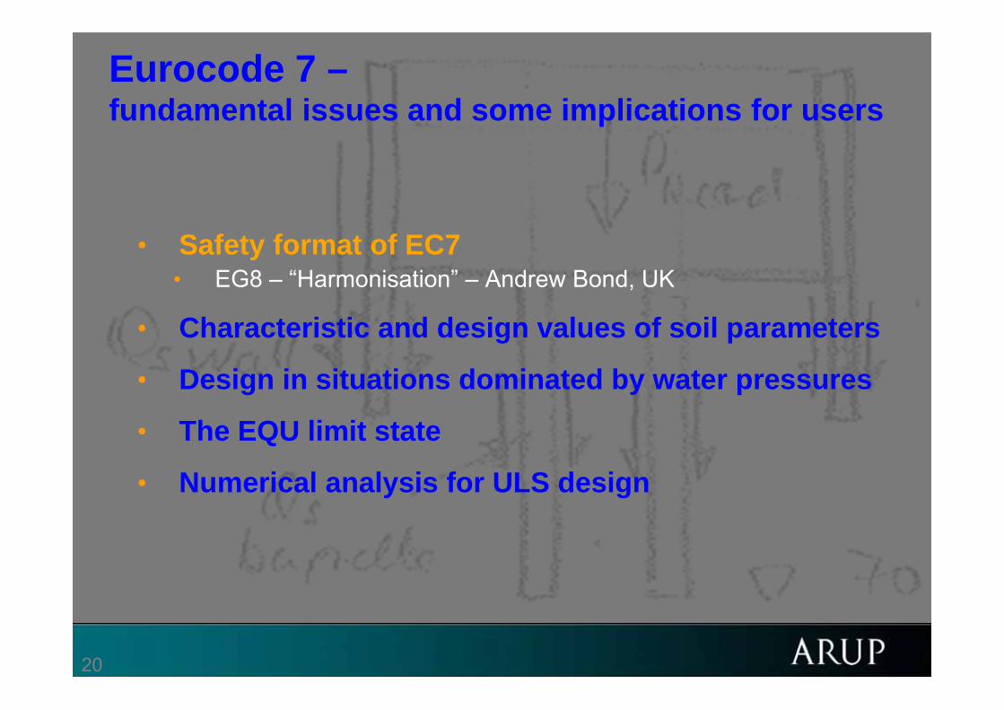
Eurocode 7 –fundamental issues and some implications for users
BP198.2 BP201.2
• Safety format of EC7• EG8 – “Harmonisation” – Andrew Bond, UK
• Characteristic and design values of soil parameters
• Design in situations dominated by water pressures
• The EQU limit state
• Numerical analysis for ULS design
21
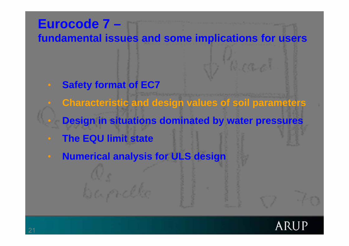
Eurocode 7 –fundamental issues and some implications for users
BP198.2 BP201.2
• Safety format of EC7
• Characteristic and design values of soil parameters
• Design in situations dominated by water pressures
• The EQU limit state
• Numerical analysis for ULS design

22
Characteristic values in EC72.4.5.2 Characteristic values of geotechnical parameters(1)P The selection of characteristic values for geotechnical parameters shall be based on derived values resulting from laboratory and field tests,
complemented by well-established experience.(2)P The characteristic value of a geotechnical parameter shall be selected as a cautious estimate of the value affecting the occurrence of the limit
state. (3)P The greater variance of c' compared to that of tan' shall be considered when their characteristic values are determined.(4)P The selection of characteristic values for geotechnical parameters shall take account of the following:-- geological and other background information, such as data from previous projects;-- the variability of the measured property values and other relevant information, e.g. from existing knowledge;-- the extent of the field and laboratory investigation;-- the type and number of samples;-- the extent of the zone of ground governing the behaviour of the geotechnical structure at the limit state being considered;-- the ability of the geotechnical structure to transfer loads from weak to strong zones in the ground.(5) Characteristic values can be lower values, which are less than the most probable values, or upper values, which are greater.(6)P For each calculation, the most unfavourable combination of lower and upper values of independent parameters shall be used.(7) The zone of ground governing the behaviour of a geotechnical structure at a limit state is usually much larger than a test sample or the zone of
ground affected in an in situ test. Consequently the value of the governing parameter is often the mean of a range of values covering a large surface or volume of the ground. The characteristic value should be a cautious estimate of this mean value.
(8) If the behaviour of the geotechnical structure at the limit state considered is governed by the lowest or highest value of the ground property, the characteristic value should be a cautious estimate of the lowest or highest value occurring in the zone governing the behaviour.
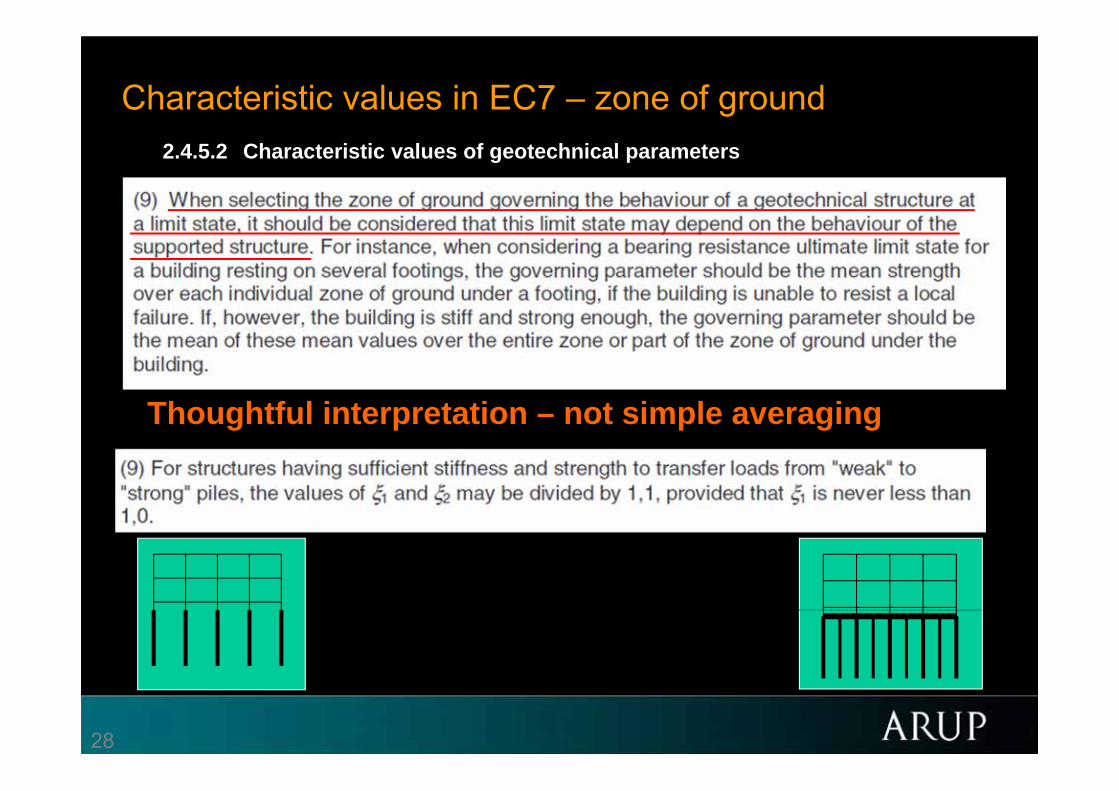
(9) When selecting the zone of ground governing the behaviour of a geotechnical structure at a limit state, it should be considered that this limit state may depend on the behaviour of the supported structure. For instance, when considering a bearing resistance ultimate limit state for a building resting on several footings, the governing parameter should be the mean strength over each individual zone of ground under a footing, if the building is unable to resist a local failure. If, however, the building is stiff and strong enough, the governing parameter should be the mean of these mean values over the entire zone or part of the zone of ground under the building.
(10) If statistical methods are employed in the selection of characteristic values for ground properties, such methods should differentiate between local and regional sampling and should allow the use of a priori knowledge of comparable ground properties.
(11) If statistical methods are used, the characteristic value should be derived such that the calculated probability of a worse value governing the occurrence of the limit state under consideration is not greater than 5%.
NOTE In this respect, a cautious estimate of the mean value is a selection of the mean value of the limited set of geotechnical parameter values, with a confidence level of 95%; where local failure is concerned, a cautious estimate of the low value is a 5% fractile.
(12)P When using standard tables of characteristic values related to soil investigation parameters, the characteristic value shall be selected as a very cautious value.

23
Characteristic values in EC7 – definition (2.4.5.2)

24
Characteristic values in EC7
2.4.3(4) also mentions:
25
EN1990 6.3.3 Design values of material or product properties

26
Characteristic values in EC7 – zone of ground
Small building on estuarine beds near slope
“Cautious” – worse than most probable.

27
Characteristic values in EC7 – zone of ground
CPT results in variable deposit
28
Characteristic values in EC7 – zone of ground2.4.5.2 Characteristic values of geotechnical parameters
Thoughtful interpretation – not simple averaging

29
Characteristic values in EC7 – definition (2.4.5.2)

30
Characteristic values in EC7• NOT a fractile of the results of particular, specified laboratory
tests on specimens of material.
• A cautious estimate of the value affecting the occurrence of the limit state
• Take account of time effects, brittleness, soil fabric and structure, the effects of construction processes and the extent of the body of ground involved in a limit state
• The designer’s expertise and understanding of the ground are all encapsulated in the characteristic value
• Consider both project-specific information and a wider body of geotechnical knowledge and experience.
• Characteristic = moderately conservative = representative (BS8002) = what good designers have always done.

31
0.5 SD below the mean?
A suggestion:
When:
• a limit state depends on the value of a parameter averaged over a large amount of ground (ie a mean value), and
• the ground property varies in a homogeneous, random manner, and
• at least 10 test values are available
Then: A value 0.5SD below the mean of the test results provides a useful indication of the characteristic value (Contribution to Discussion Session 2.3, XIV ICSMFE, Hamburg. Balkema., Schneider H R (1997) Definition and determination of characteristic soil properties. Discussion to ISSMFE Conference, Hamburg.)

32
0.5 SD below the mean?- a useful consideration, not a rule
C:\bx\EC7\[EC7.xls] 26-May-03 10:10
0
0.2
0.4
0.6
0.8
1
1.2
-3 -2.5 -2 -1.5 -1 -0.5 0 0.5 1
5% fractile of test resuts
5% fractile of mean values
Results of soil tests
MeanSD from mean
More remote when dependent on specific small zone.
33
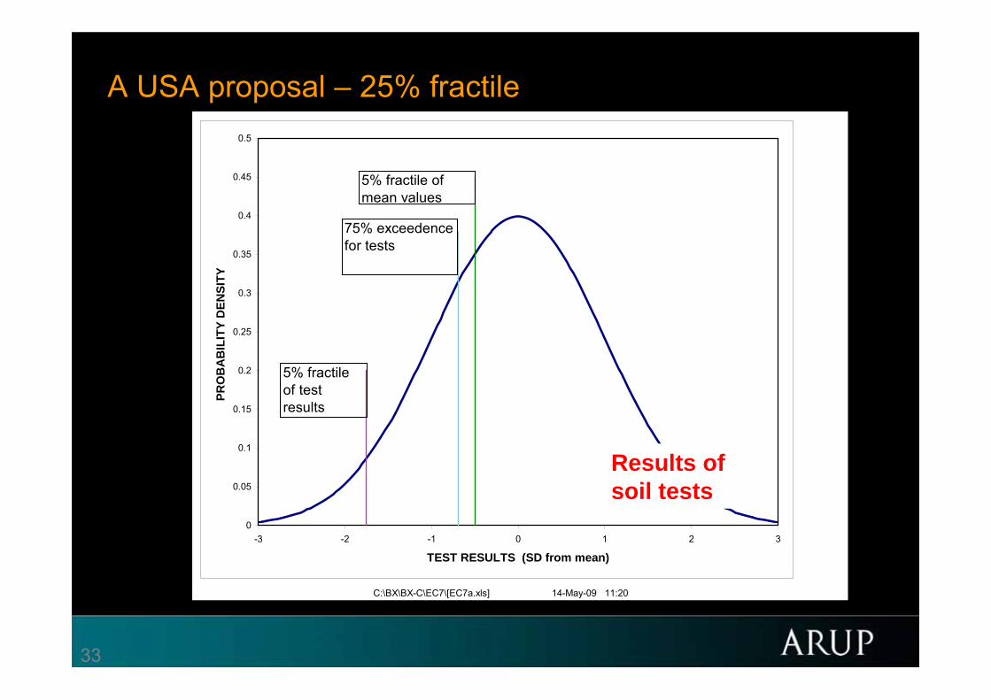
A USA proposal – 25% fractile
C:\BX\BX-C\EC7\[EC7a.xls] 14-May-09 11:20
0
0.05
0.1
0.15
0.2
0.25
0.3
0.35
0.4
0.45
0.5
-3 -2 -1 0 1 2 3
TEST RESULTS (SD from mean)
PRO
BA
BIL
ITY
DEN
SITY
5% fractile of test results
5% fractile of mean values
75% exceedence for tests
Results of soil tests
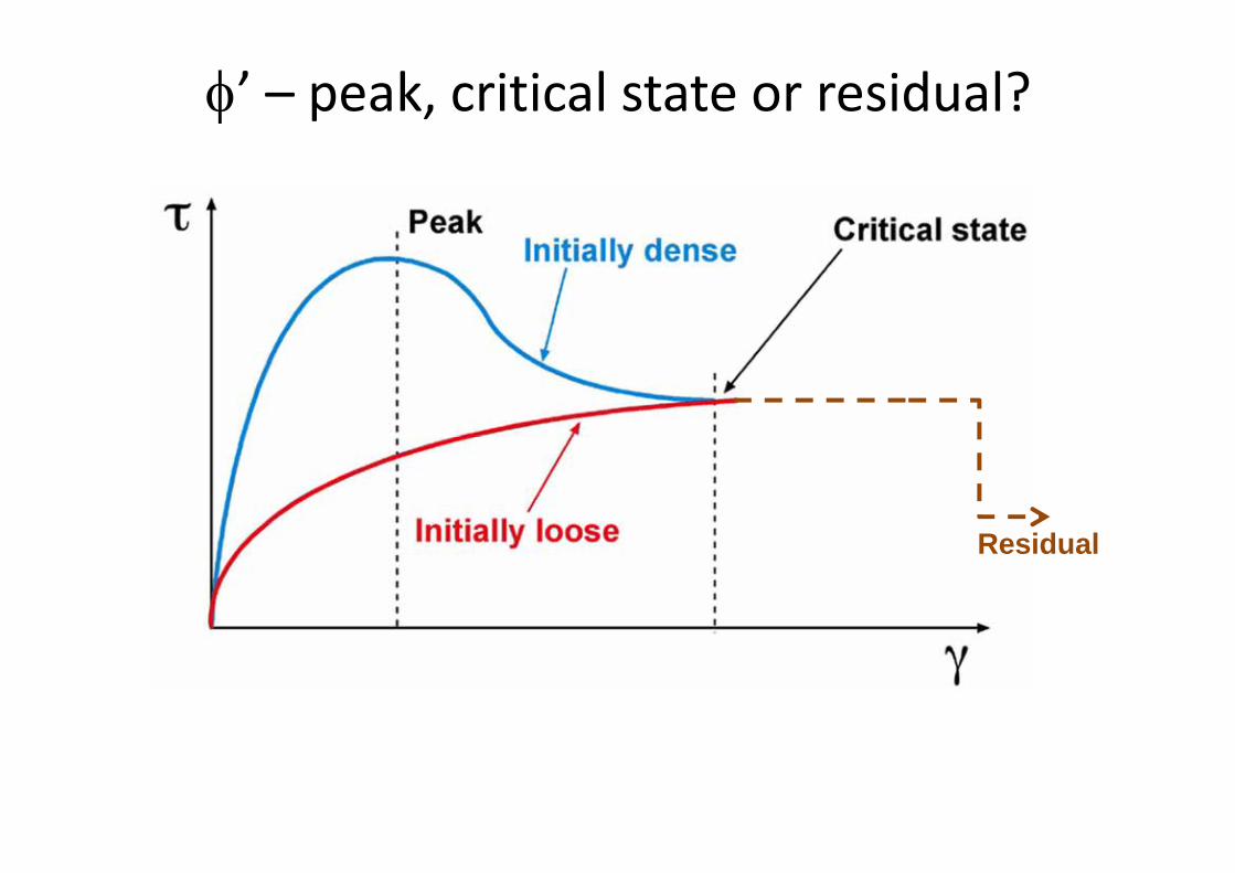
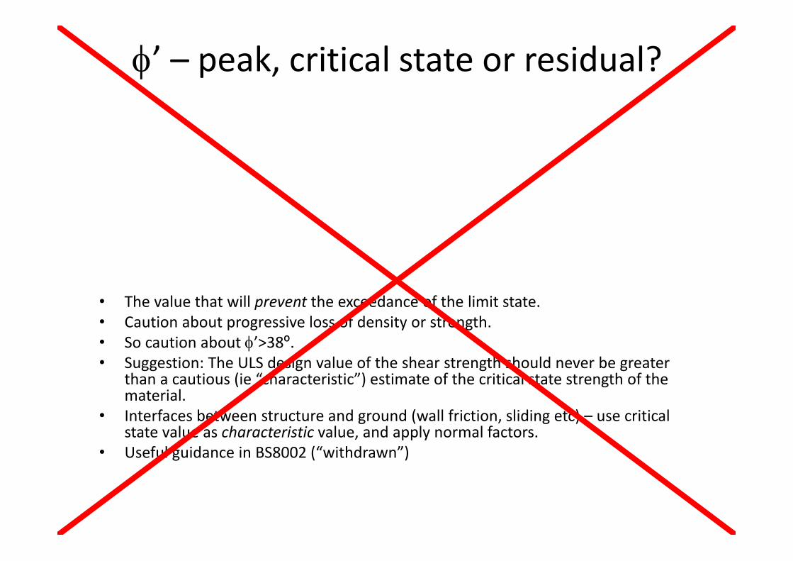
’ – peak, critical state or residual?
Residual

Angle of shearing resistance ’
’
c’ ?

’ – peak, critical state or residual?
Residual
• The value that will prevent the exceedance of the limit state.• Caution about progressive loss of density or strength.• So caution about ’>38º.• Suggestion: The ULS design value of the shear strength should never be greater
than a cautious (ie “characteristic”) estimate of the critical state strength of the material.
• Interfaces between structure and ground (wall friction, sliding etc) – use critical state value as characteristic value, and apply normal factors.
• Useful guidance in BS8002 (“withdrawn”)

’ – peak, critical state or residual?
Residual
’ – peak, critical state or residual?
• The value that will prevent the exceedance of the limit state.• Caution about progressive loss of density or strength.• So caution about ’>38º.• Suggestion: The ULS design value of the shear strength should never be greater
than a cautious (ie “characteristic”) estimate of the critical state strength of the material.
• Interfaces between structure and ground (wall friction, sliding etc) – use critical state value as characteristic value, and apply normal factors.
• Useful guidance in BS8002 (“withdrawn”)

’ – peak, critical state or residual?
• Useful guidance in BS8002 (“withdrawn”)
Critical state

40
The best GI is as many different tests as possible.
Paul Mayne
• So we have to be able to consider results from different tests together.
• Some more definite than others.
• May conflict.

Data from more than one source
Bored pile

Conflicting data
The code drafters could not have known about this uncertainty

43
Eurocode 7 –fundamental issues and some implications for users
BP198.2 BP201.2
• Safety format of EC7
• Characteristic and design values of soil parameters• EG11 - Lovisa Moritz, Sweden
• Design in situations dominated by water pressures
• The EQU limit state
• Numerical analysis for ULS design

44
Eurocode 7 –fundamental issues and some implications for users
BP198.2 BP201.2
• Safety format of EC7
• Characteristic and design values of soil parameters
• Design in situations dominated by water pressures
• The EQU limit state
• Numerical analysis for ULS design

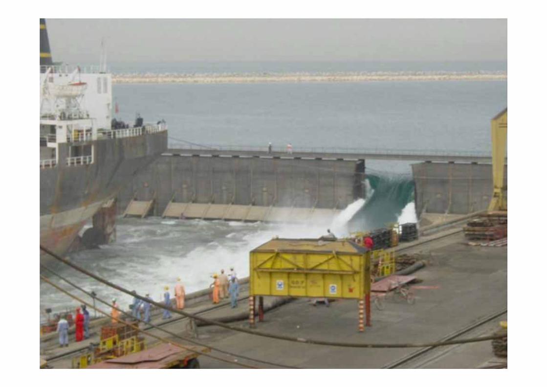
Dubai Dry Dock BP184.14

Dubai Dry Dock BP184.16
Factors of safety ?!?
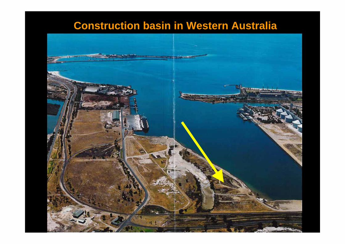
Construction basin in Western Australia


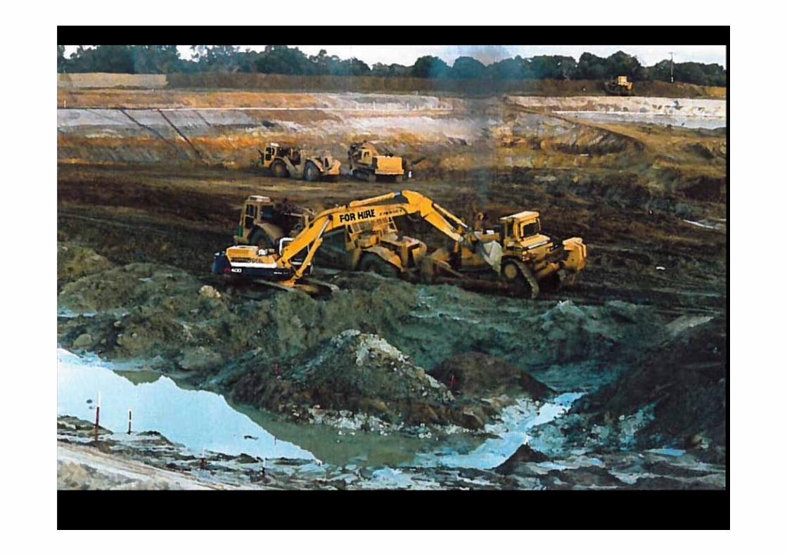
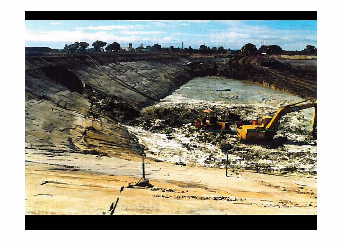
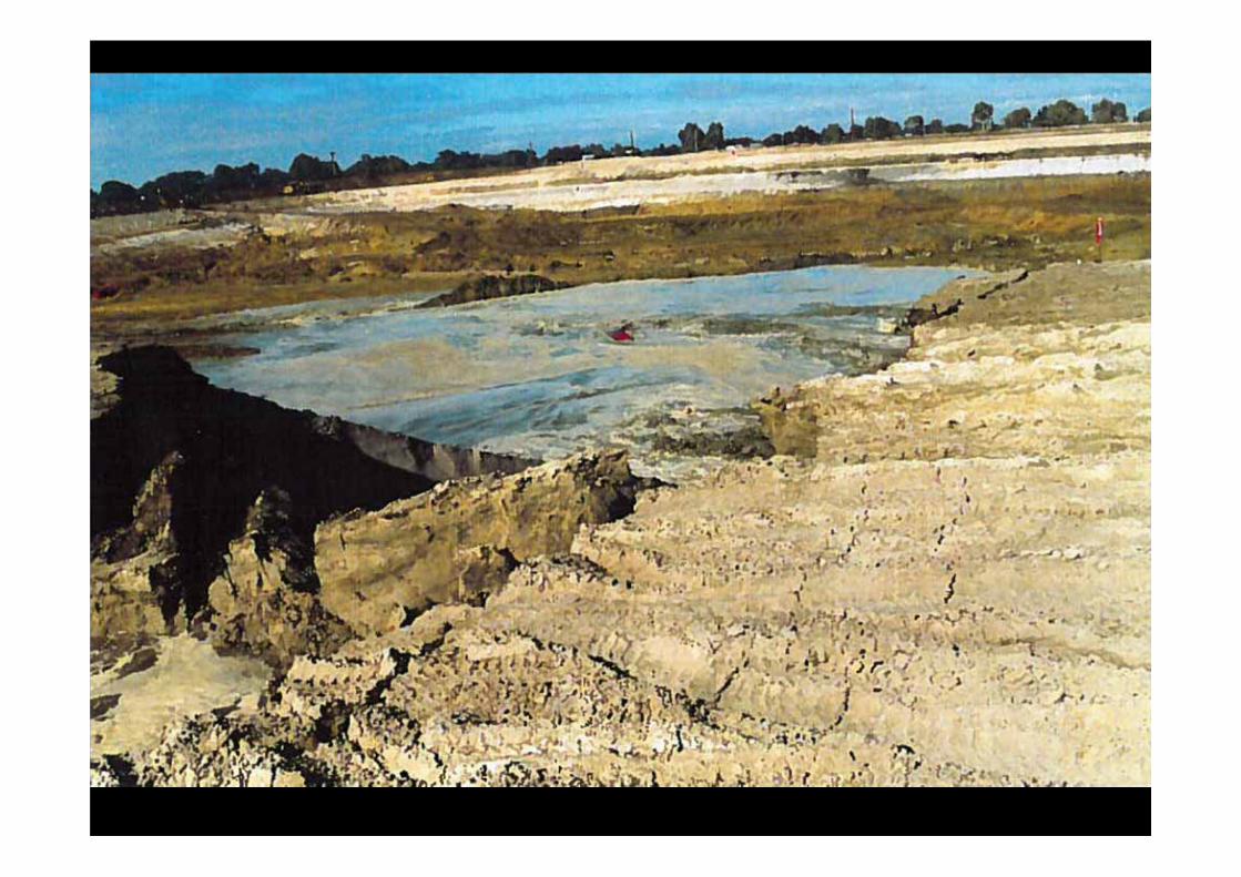

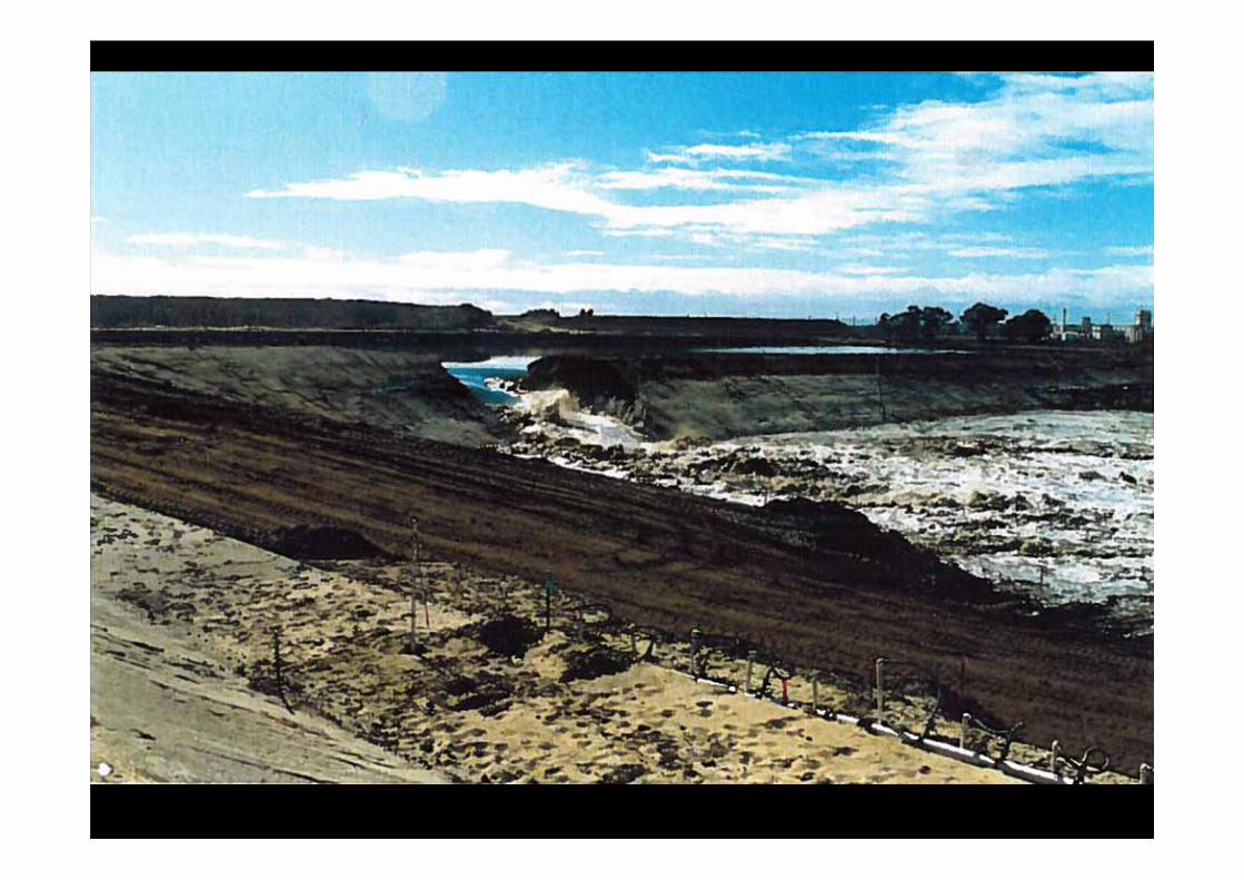

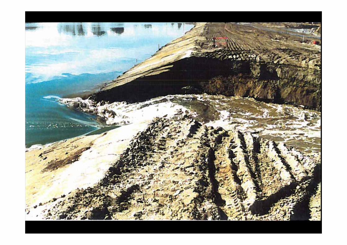

Water has a way of seeping between any two theories!
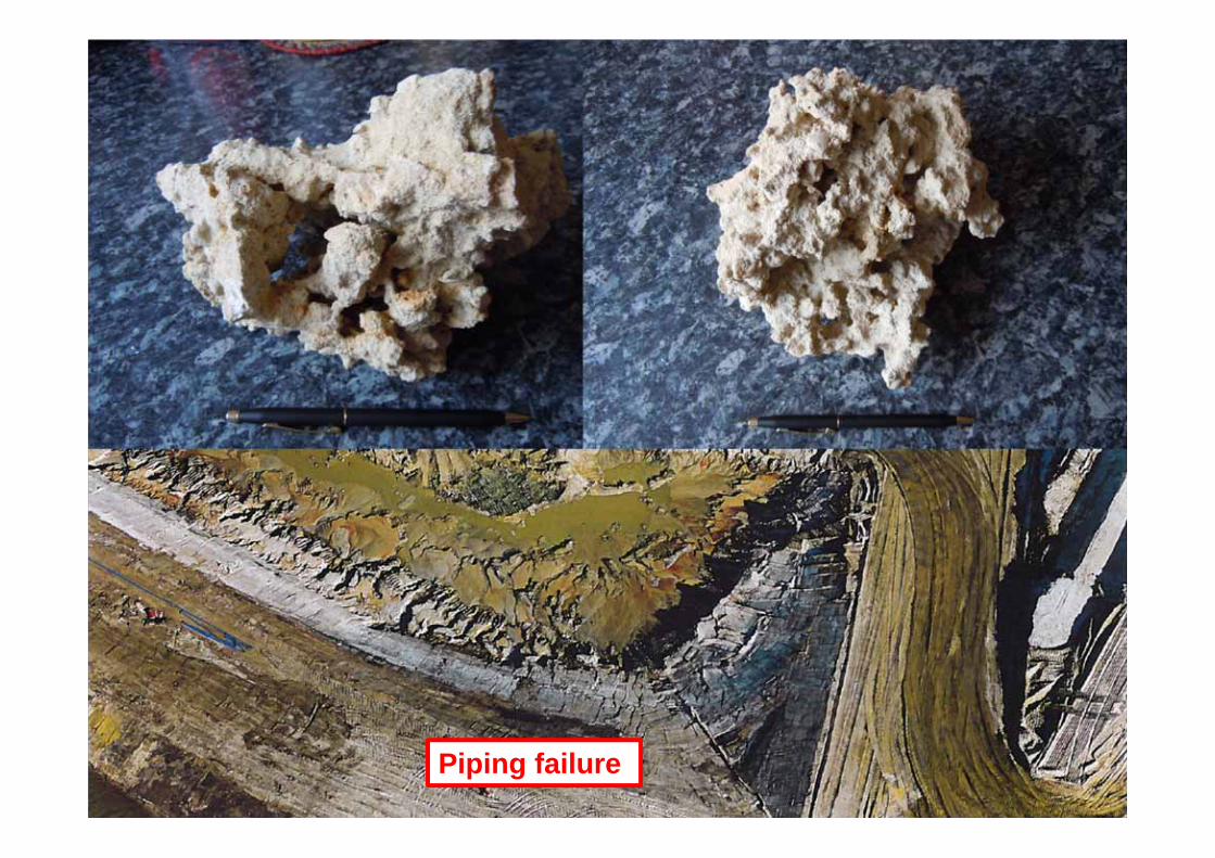
Piping failure

60
61
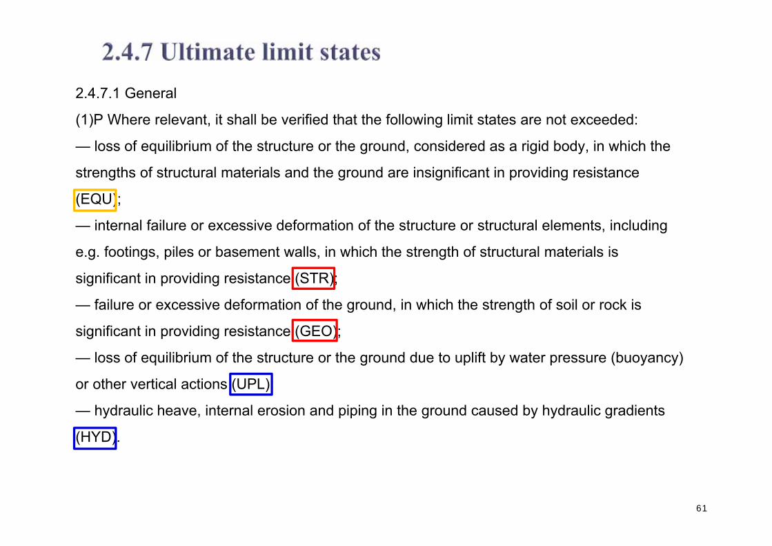
2.4.7.1 General
(1)P Where relevant, it shall be verified that the following limit states are not exceeded:
— loss of equilibrium of the structure or the ground, considered as a rigid body, in which the
strengths of structural materials and the ground are insignificant in providing resistance
(EQU);
— internal failure or excessive deformation of the structure or structural elements, including
e.g. footings, piles or basement walls, in which the strength of structural materials is
significant in providing resistance (STR);
— failure or excessive deformation of the ground, in which the strength of soil or rock is
significant in providing resistance (GEO);
— loss of equilibrium of the structure or the ground due to uplift by water pressure (buoyancy)
or other vertical actions (UPL);
— hydraulic heave, internal erosion and piping in the ground caused by hydraulic gradients
(HYD).

62
2.4.7.1 General
(1)P Where relevant, it shall be verified that the following limit states are not exceeded:
— loss of equilibrium of the structure or the ground, considered as a rigid body, in which the
strengths of structural materials and the ground are insignificant in providing resistance
(EQU);
— internal failure or excessive deformation of the structure or structural elements, including
e.g. footings, piles or basement walls, in which the strength of structural materials is
significant in providing resistance (STR);
— failure or excessive deformation of the ground, in which the strength of soil or rock is
significant in providing resistance (GEO);
— loss of equilibrium of the structure or the ground due to uplift by water pressure (buoyancy)
or other vertical actions (UPL);
— hydraulic heave, internal erosion and piping in the ground caused by hydraulic gradients
(HYD).
a a
W W
M
F1 F2
b
63
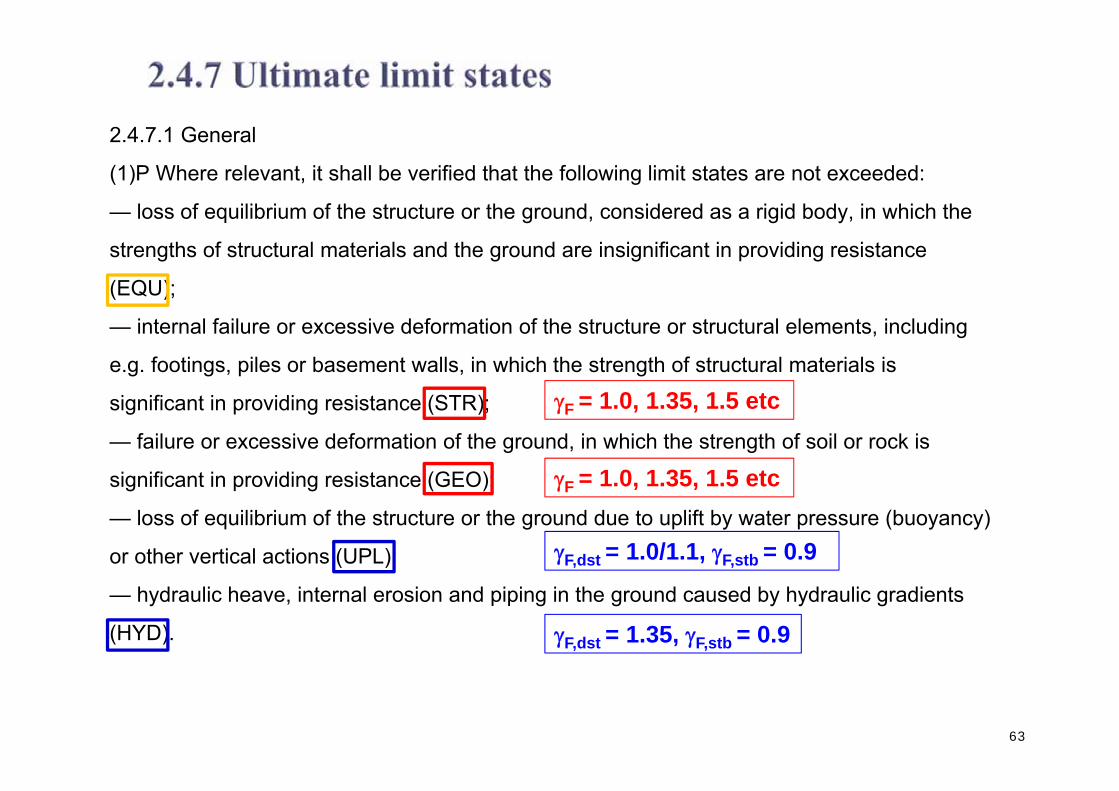
2.4.7.1 General
(1)P Where relevant, it shall be verified that the following limit states are not exceeded:
— loss of equilibrium of the structure or the ground, considered as a rigid body, in which the
strengths of structural materials and the ground are insignificant in providing resistance
(EQU);
— internal failure or excessive deformation of the structure or structural elements, including
e.g. footings, piles or basement walls, in which the strength of structural materials is
significant in providing resistance (STR);
— failure or excessive deformation of the ground, in which the strength of soil or rock is
significant in providing resistance (GEO);
— loss of equilibrium of the structure or the ground due to uplift by water pressure (buoyancy)
or other vertical actions (UPL);
— hydraulic heave, internal erosion and piping in the ground caused by hydraulic gradients
(HYD).
F = 1.0, 1.35, 1.5 etc
F = 1.0, 1.35, 1.5 etc
F,dst = 1.0/1.1, F,stb = 0.9
F,dst = 1.35, F,stb = 0.9

64

65
(9)P Actions in which ground- and free-water forces predominate shall be identified for special consideration with regard to deformations, fissuring, variable permeability and erosion.
NOTE Unfavourable (or destabilising) and favourable (or stabilising) permanent actions may in some situations be considered as coming from a single source. If they are considered so, a single partial factor may be applied to the sum of these actions or to the sum of their effects.

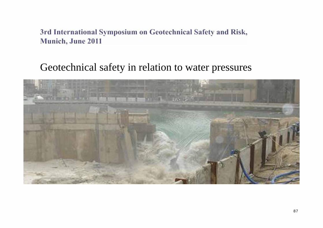
Geotechnical safety in relation to water pressures
B. SimpsonArup Geotechnics, London, UK
N. VogtTechnische Universität München,Zentrum Geotechnik, Munich, Germany
A. J. van SetersFugro GeoServices, The Netherlands
66

67

• Introduction• Case histories of failures caused by water pressure• Existing geotechnical codes and guidance documents• Requirements of EC7• Some fundamental considerations• Examples• Recommendations
68
Geotechnical safety in relation to water pressures
B. SimpsonArup Geotechnics, London, UK
N. VogtTechnische Universität München,Zentrum Geotechnik, Munich, Germany
A. J. van SetersFugro GeoServices, The Netherlands

69

70

• Need robustness• Accommodate the worst water pressures• Apply the “single source” principle• Don’t factor water density (?)• Use of an offset in water level (?)• Reduced factor on favourable weight (?)• The “star” approach (?)• A “middle 2/3rds” rule (?)• Use engineering expertise
71

72

73
1m rise in water level multiplies BM by about 2.5 – outside the range allowed by factors on the water pressure or water force.

74
G;stb & G,dst2. Buoyant weight3. Factor water
density4. Water unfactored
Ustb
Udst
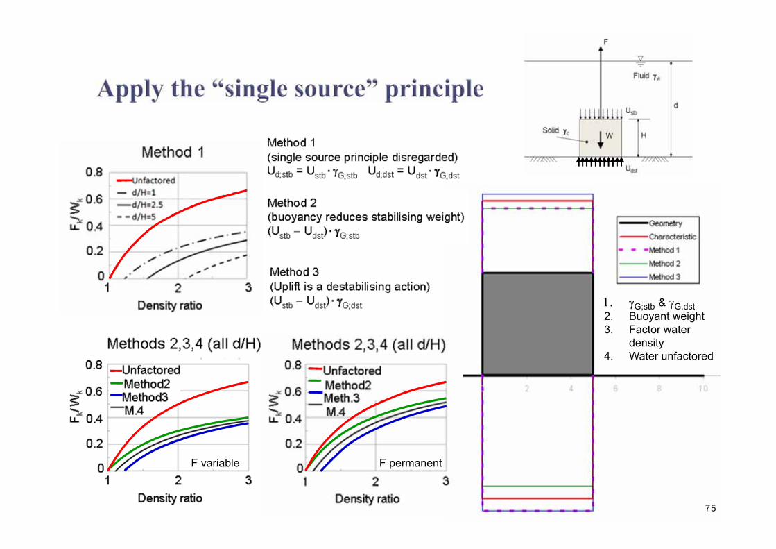
75
G;stb & G,dst2. Buoyant weight3. Factor water
density4. Water unfactored
F variable F permanent

76
• Should generally be avoided• Use unfactored water pressures and forces?• Don’t factor density but factor pressures (AvS)?• Don’t factor pressures but factor forces (NV)?• At some point, equilibrium is not preserved. But
the question is – where?• The problems are less for DA1, but not removed.

h
77

Number of piles required (normalised). (a) unfactored, (b) pile resistance factored, (c) G = 1.35 on water pressure, (d) water table adjusted, (e) UPL,
0
1
2
0 0.2 0.4 0.6 0.8 1
n.Rk
/Ww
h/D
(a)
(b)
(c)
(d)
(e)
(f)
0
0.2
0.4
0.1 0.2 0.3 0.4
n.Rk
/Ww
h/D
(a)(b)(c)(d)(e)(f)
h/D
(a)
(b)
(c) (d)(e)
(f)
h/D0.2 0.3 0.4
00.1
0.2
0.4
0
1
2
n·R
k/Ww
n·R
k/Ww
0 0.2 0.4 0.6 0.8 1
78

79
The possibility of a reduced factor on favourable weight, perhaps between 0.8 and 0.9 should be considered.
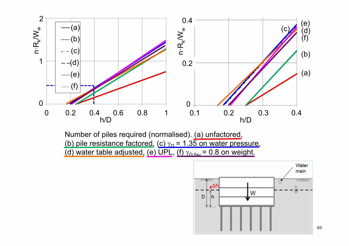
Number of piles required (normalised). (a) unfactored, (b) pile resistance factored, (c) G = 1.35 on water pressure, (d) water table adjusted, (e) UPL, (f) G;fav = 0.8 on weight.
0
1
2
0 0.2 0.4 0.6 0.8 1
n.Rk
/Ww
h/D
(a)
(b)
(c)
(d)
(e)
(f)
0
0.2
0.4
0.1 0.2 0.3 0.4
n.Rk
/Ww
h/D
(a)(b)(c)(d)(e)(f)
h/D
(a)
(b)
(c) (d)(e)
(f)
h/D0.2 0.3 0.4
00.1
0.2
0.4
0
1
2
n·R
k/Ww
n·R
k/Ww
0 0.2 0.4 0.6 0.8 1
80

81
EC7 2.4.7.3.2(2) In some design situations, the application of partial factors to actions coming from or through the soil (such as earth or water pressures) could lead to design values which are unreasonable or even physically impossible. In these situations, the factors may be applied directly to the effects of actions derived from representative values of the actions.
Apply only to structural bending moments etc, or more generally?

• Depending on other factors, it might be necessary to enhance the loads derived from water pressure (or load effects such as an uplifting force), even when they are very certain.
• Problem in cases where it is directly equivalent to factoring water pressures
82
83
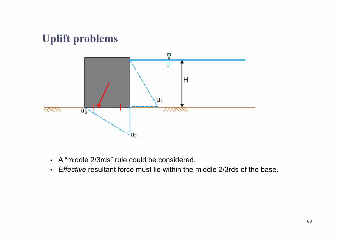
• A “middle 2/3rds” rule could be considered.• Effective resultant force must lie within the middle 2/3rds of the base.

84

• Need robustness• Accommodate the worst water pressures• Apply the “single source” principle• Don’t factor water density (?)• Use of an offset in water level (?)• Reduced factor on favourable weight (?)• The “star” approach (?)• A “middle 2/3rds” rule (?)• Use engineering expertise
85
86
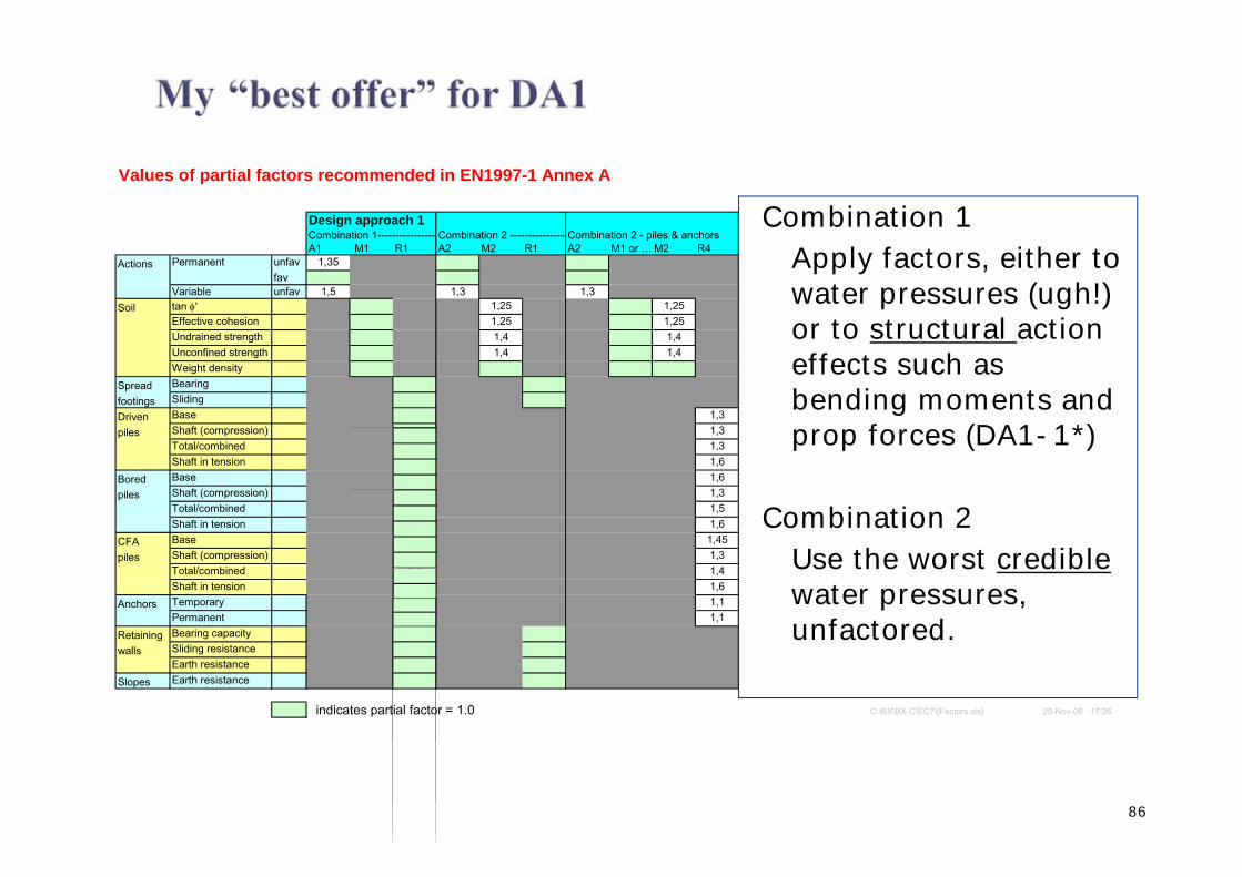
Values of partial factors recommended in EN1997-1 Annex A
Design approach 1 Design approach 2 Design approach 3Combination 1---------------- Combination 2 ----------------Combination 2 - piles & anchors DA2 - Comb 1 DA2 - Slopes DA3A1 M1 R1 A2 M2 R1 A2 M1 or … M2 R4 A1 M1 R2 A1 M=R2 A1 A2 M2 R3
Actions unfav 1,35 1,35 1,35 1,35favunfav 1,5 1,3 1,3 1,5 1,5 1,5 1,3
Soil tan ' 1,25 1,25 StructuraGeotech 1,25Effective cohesion 1,25 1,25 actions actions 1,25Undrained strength 1,4 1,4 1,4Unconfined strength 1,4 1,4 1,4Weight density
Spread Bearing 1,4footings Sliding 1,1Driven Base 1,3 1,1piles Shaft (compression) 1,3 1,1
Total/combined 1,3 1,1Shaft in tension 1,25 1,6 1,15 1,1
Bored Base 1,25 1,6 1,1piles Shaft (compression) 1,0 1,3 1,1
Total/combined 1,15 1,5 1,1Shaft in tension 1,25 1,6 1,15 1,1
CFA Base 1,1 1,45 1,1piles Shaft (compression) 1,0 1,3 1,1
Total/combined 1,1 1,4 1,1Shaft in tension 1,25 1,6 1,15 1,1
Anchors Temporary 1,1 1,1 1,1Permanent 1,1 1,1 1,1
Retaining Bearing capacity 1,4walls Sliding resistance 1,1
Earth resistance 1,4Slopes Earth resistance 1,1
indicates partial factor = 1.0 C:\BX\BX-C\EC7\[Factors.xls] 25-Nov-06 17:26
Permanent
Variable
Combination 1Apply factors, either to water pressures (ugh!) or to structural action effects such as bending moments and prop forces (DA1-1*)
Combination 2Use the worst crediblewater pressures, unfactored.
Geotechnical safety in relation to water pressures
B. SimpsonArup Geotechnics, London, UK
N. VogtTechnische Universität München,Zentrum Geotechnik, Munich, Germany
A. J. van SetersFugro GeoServices, The Netherlands
87
88
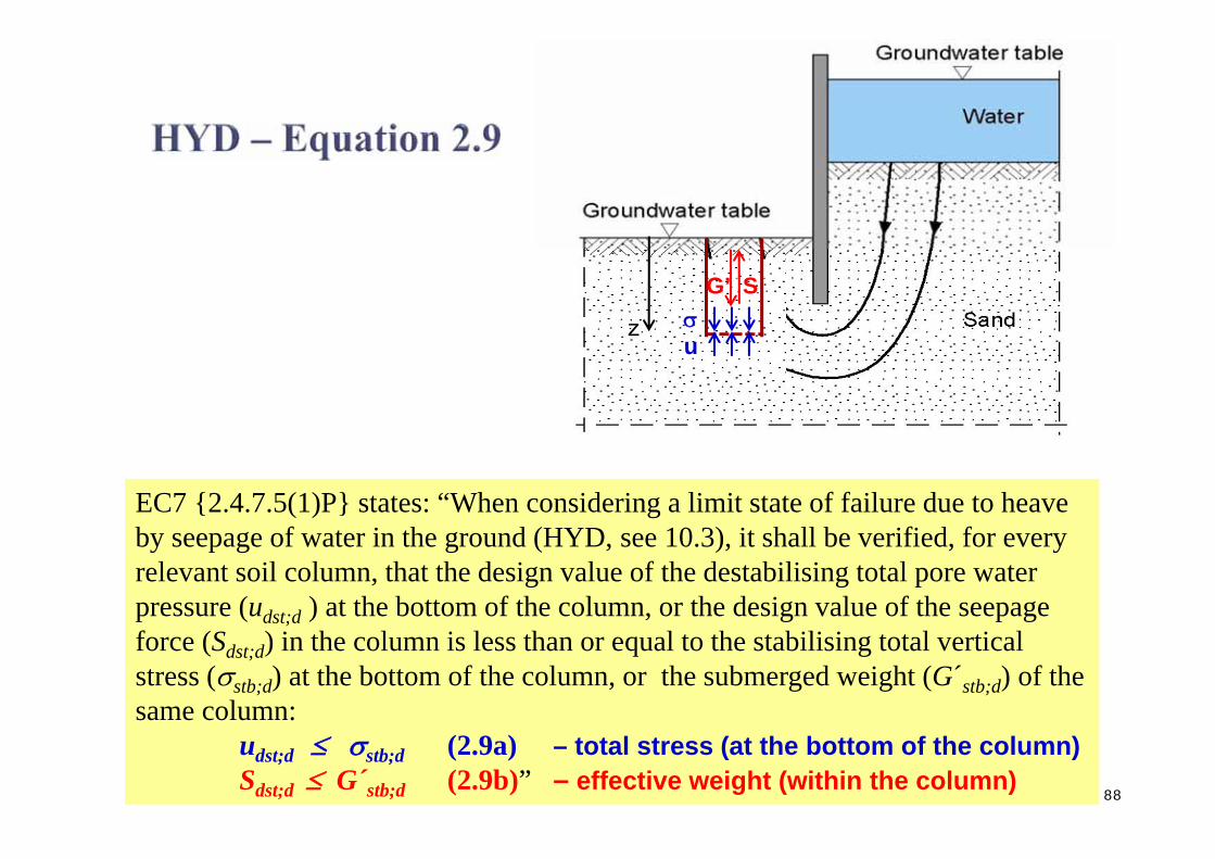
EC7 {2.4.7.5(1)P} states: “When considering a limit state of failure due to heave by seepage of water in the ground (HYD, see 10.3), it shall be verified, for every relevant soil column, that the design value of the destabilising total pore water pressure (udst;d ) at the bottom of the column, or the design value of the seepage force (Sdst;d) in the column is less than or equal to the stabilising total vertical stress (stb;d) at the bottom of the column, or the submerged weight (G´stb;d) of the same column:
udst;d stb;d (2.9a) – total stress (at the bottom of the column)Sdst;d G´stb;d (2.9b)” – effective weight (within the column)
u
G’ S
z

89
EC7 {2.4.7.5(1)P} states: “When considering a limit state of failure due to heave by seepage of water in the ground (HYD, see 10.3), it shall be verified, for every relevant soil column, that the design value of the destabilising total pore water pressure (udst;d ) at the bottom of the column, or the design value of the seepage force (Sdst;d) in the column is less than or equal to the stabilising total vertical stress (stb;d) at the bottom of the column, or the submerged weight (G´stb;d) of the same column:
udst;d stb;d (2.9a) – total stress (at the bottom of the column)Sdst;d G´stb;d (2.9b)” – effective weight (within the column)
u
G’ S
Annex A of EC7 provides values for partial factors to be used for HYD, G;dst = 1.35 and G;stb = 0.9. But the code does not state what quantities are to be factored.Maybe:G;dst udst;k G;stb stb;k (2.9a)andG;dst Sdst;k G;stb G´stb;k (2.9b)
In this format, the factors are applied to different quantities in 2.9 a and b.
z

90
H=?
1m
3m
7m
Uniform permeability

91
udst;d stb;d (2.9a) – total stress (at the bottom of the column)Sdst;d G´stb;d (2.9b)” – effective weight (within the column)
Apply G;dst = 1.35 to: Apply G;stb = 0.9 to: HPore water pressure udst;k Total stress stb;k 2.78Seepage force Sdst;k Buoyant weight G´stb;k 6.84Excess pore pressure udst;k - wz Buoyant density 6.84Excess head (udst;k - wz) /w Buoyant density 6.84Excess pore pressure or excess head Total density 6.1
Orr, T.L.L. 2005. Model Solutions for Eurocode 7 Workshop Examples. Trinity College, Dublin.
G;dst udst;k G;stb stb;k (2.9a)
G;dst Sdst;k G;stb G´stb;k (2.9b)

92
udst;d stb;d (2.9a) – total stress (at the bottom of the column)Sdst;d G´stb;d (2.9b)” – effective weight (within the column)
Apply G;dst = 1.35 to: Apply G;stb = 0.9 to: HPore water pressure udst;k Total stress stb;k 2.78Seepage force Sdst;k Buoyant weight G´stb;k 6.84Excess pore pressure udst;k - wz Buoyant density 6.84Excess head (udst;k - wz) /w Buoyant density 6.84Excess pore pressure or excess head Total density 6.1

93
Eurocode 7 –fundamental issues and some implications for users
BP198.2 BP201.2
• Safety format of EC7
• Characteristic and design values of soil parameters
• Design in situations dominated by water pressures• EG9 – Norbert Vogt, Germany
• The EQU limit state
• Numerical analysis for ULS design

94
Eurocode 7 –fundamental issues and some implications for users
BP198.2 BP201.2
• Safety format of EC7
• Characteristic and design values of soil parameters
• Design in situations dominated by water pressures
• The EQU limit state
• Numerical analysis for ULS design

95
Paper on the EQU problem
96
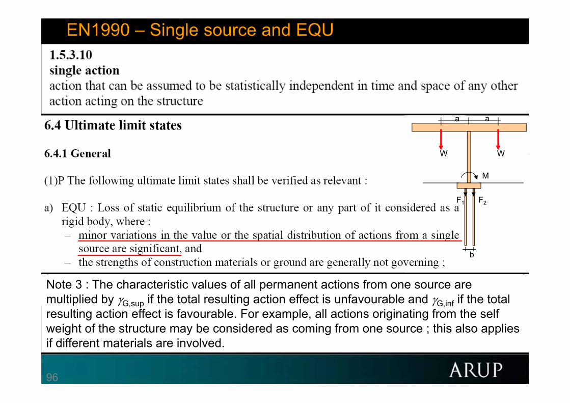
EN1990 – Single source and EQU
Note 3 : The characteristic values of all permanent actions from one source are multiplied by G,sup if the total resulting action effect is unfavourable and G,inf if the total resulting action effect is favourable. For example, all actions originating from the self weight of the structure may be considered as coming from one source ; this also applies if different materials are involved.
a a
W W
M
F1 F2
b

97
a a
W W
M
F1 F2
b

98
What if EQU not balanced? How to involve material strength?
Three views:
1. Material demand only calculated when design W’s balanced.
2. Nonsense! Must apply G = 1.35, 1.0
3. Treat EQU as another load case. Check M, F1, F2 for G = 0.9, 1.1 OR G = 1.15, 1.35
Ga,k Gb,k
Pk.stb a/2 b
a a
W W
M
F1 F2
b
For a=5bM/Wa F/W
0 1.35
0.35 2.925, -0.575 (tension)
0.2 2 00.2 2.25 0.25

99
Overturning on “infinitely strong” rock.
• For finite strength, check Wx1.0; Fx1.35 (or material factor on tan of sand). Check ground and structure.
• ? For infinite strength, check “overturning” for Wx0.9; Fx1.1 ?
• Less severe design loading because rock “infinitely strong”?
• Less severe loading for overturning than for sliding?
• Even the structure is not infinitely strong. So not a real problem?
• But no problem if EQU treated as another load case.
Dry sand (loose)
Infinitely strong rock
b
WF

100
Soil strength also involved
• Nobody wants EQU to rule.
• Could make a “special” rule to prevent EQU check.
• ? Better to require the check “in principle” and arrange factors so that it will never be critical.
Inclination of slip surface > d
Inclination of slip surface < d
1
2
Homogeneous dry sand
Q
Wh
d=0
(1.5)
(0.9 < 1.0)

101
EN1997 UKNA – Partial material factors reduced for EQU

102
Eurocode 7 –fundamental issues and some implications for users
BP198.2 BP201.2
• Safety format of EC7
• Characteristic and design values of soil parameters
• Design in situations dominated by water pressures
• The EQU limit state• TC250 group including chair of SC7
• Numerical analysis for ULS design
103
Eurocode 7 –fundamental issues and some implications for users
BP198.2 BP201.2
• Safety format of EC7
• Characteristic and design values of soil parameters
• Design in situations dominated by water pressures
• The EQU limit state
• Numerical analysis for ULS design

104
Eurocode 7 –fundamental issues and some implications for users
BP198.2 BP201.2
• Safety format of EC7
• Characteristic and design values of soil parameters
• Design in situations dominated by water pressures
• The EQU limit state
• Numerical analysis for ULS design• What to factor and when to factor?

105
Values of partial factors recommended in EN1997-1 Annex A
Design approach 1 Design approach 2 Design approach 3Combination 1---------------- Combination 2 ----------------Combination 2 - piles & anchors DA2 - Comb 1 DA2 - Slopes DA3A1 M1 R1 A2 M2 R1 A2 M1 or … M2 R4 A1 M1 R2 A1 M=R2 A1 A2 M2 R3
Actions unfav 1,35 1,35 1,35 1,35favunfav 1,5 1,3 1,3 1,5 1,5 1,5 1,3
Soil tan ' 1,25 1,25 StructuraGeotech 1,25Effective cohesion 1,25 1,25 actions actions 1,25Undrained strength 1,4 1,4 1,4Unconfined strength 1,4 1,4 1,4Weight density
Spread Bearing 1,4footings Sliding 1,1Driven Base 1,3 1,1piles Shaft (compression) 1,3 1,1
Total/combined 1,3 1,1Shaft in tension 1,25 1,6 1,15 1,1
Bored Base 1,25 1,6 1,1piles Shaft (compression) 1,0 1,3 1,1
Total/combined 1,15 1,5 1,1Shaft in tension 1,25 1,6 1,15 1,1
CFA Base 1,1 1,45 1,1piles Shaft (compression) 1,0 1,3 1,1
Total/combined 1,1 1,4 1,1Shaft in tension 1,25 1,6 1,15 1,1
Anchors Temporary 1,1 1,1 1,1Permanent 1,1 1,1 1,1
Retaining Bearing capacity 1,4walls Sliding resistance 1,1
Earth resistance 1,4Slopes Earth resistance 1,1
indicates partial factor = 1.0 C:\BX\BX-C\EC7\[Factors.xls] 25-Nov-06 17:26
Permanent
Variable
Partial factors recommended in EN1997-1 Annex A (+UKNA) BP111.19
BP124-T2.14 BP124-A2.12 BP168.81 BP188.34
(+ UKNA)
• Easy to factor primary input –material strengths and actions
• Difficult to factor geotechnical resistances and action effects

106
Fundamental limit state requirement BP193.8
Ed Rd
E{ Fd ; Xd ; ad} = Ed Rd = R{ Fd ; Xd ; ad}
E{F Frep; Xk/M; ad} = Ed Rd = R{F Frep; Xk/M; ad}
or E{F Frep; Xk/M; ad} = Ed Rd = Rk/R = RnR (LRFD)
or E Ek = Ed Rd = Rk/R
so in total
E E{F Frep; Xk/M; ad} = Ed Rd = R{F Frep; Xk/M; ad}/R
• Reduce strength, increase the loads, and check equilibrium
OR
• Find the remaining FOS?
OR
• “c- reduction”
107
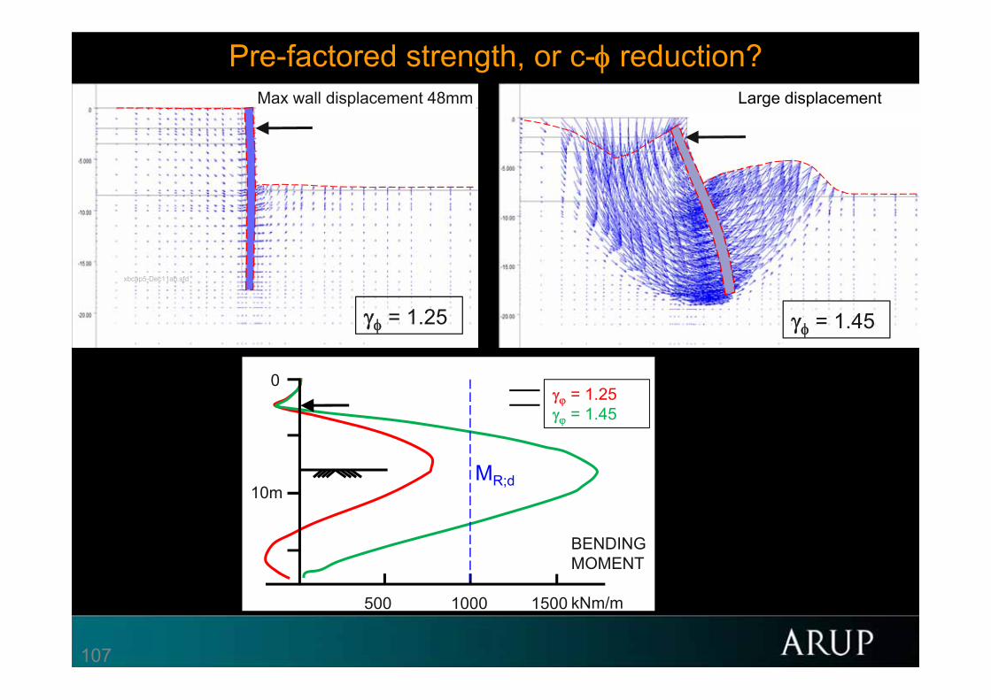
Max wall displacement 48mm Max wall displacement 48mmMax wall displacement 48mm
= 1.25
0
10m
500 1000 1500
BENDING MOMENT
kNm/m
= 1.25 = 1.45
MR;d
xbcap5-Dec11ab.sfd
Large displacement
= 1.45
Pre-factored strength, or c- reduction?
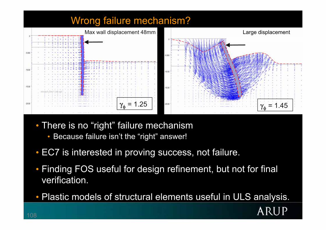
108
Wrong failure mechanism?
• There is no “right” failure mechanism• Because failure isn’t the “right” answer!
• EC7 is interested in proving success, not failure.
• Finding FOS useful for design refinement, but not for final verification.
• Plastic models of structural elements useful in ULS analysis.
Max wall displacement 48mm Max wall displacement 48mmMax wall displacement 48mm
= 1.25
xbcap5-Dec11ab.sfd
Large displacement
= 1.45

109
Factoring advanced models – ′, c′, cu not explicit parameters
• eg Cam Clay, BRICK etc
• Change to Mohr-Coulomb for the factored calculation?
• If c′=′ this is the factor on drained strength, however derived.
• Consider: is the model’s drained strength more or less reliable than those used in conventional practice?
• eg the model might take good account of combinations of principal stresses, direction (anisotropy), stress level etc.
• Possibly modify factors in the light of this.

110
Undrained strength in effective stress models
• Reliable computation of undrained strength from effective stress parameters is very difficult.
• EC7 generally requires a higher factor on undrained strength (eg 1.4 on cu) than on effective stress parameters (eg 1.25 on c′, tan′).

111
Undrained strength in effective stress models
• Reliable computation of undrained strength from effective stress parameters is very difficult.
• EC7 generally requires a higher factor on undrained strength (eg 1.4 on cu) than on effective stress parameters (eg 1.25 on c′, tan′).
• The drafters assumed that effective stress parameters would be used only for drained states.
• The higher factor (eg 1.4) was considered appropriate for characteristic values of cu based on measurement, which is generally more reliable than values computed from effective stress parameters.
• So it is unreasonable to adopt a lower value for the latter.

112
Time-dependent analysis
• Beyond EC7!

113
ULS for staged construction – single propped excavation
Factor material strengths
Initial state
Excavate to 5m –wall cantilevering
Could be critical for wall bending moment
Install prop at 4m depth
Excavate to 10m
Could be critical for wall length, bending moment and prop force
Compute using characteristic parameters
Compute using factored parameters
Excavate to 5m –wall cantilevering
Install prop at 4m depth
Excavate to 10m
No further factors on strut forces or BMs
Compute using factored strength
Apply factors on strut forces or BMs
Compute using unfactored parameters
No further factors on strut forces or BMs
Initial state?
114
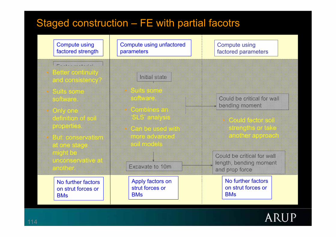
Staged construction – FE with partial facotrs
Factor material strengths
Initial state
Excavate to 5m –wall cantilevering
Could be critical for wall bending moment
Install prop at 4m depth
Excavate to 10m
Could be critical for wall length, bending moment and prop force
Compute using characteristic parameters
Compute using factored parameters
Excavate to 5m –wall cantilevering
Install prop at 4m depth
Excavate to 10m
No further factors on strut forces or BMs
Compute using factored strength
Apply factors on strut forces or BMs
Compute using unfactored parameters
No further factors on strut forces or BMs
Initial state?
• Better continuityand consistency?
• Suits some software.
• Only one definition of soil properties.
• But: conservatism at one stage might be unconservative at another.
• Suits some software.
• Combines an ‘SLS’ analysis
• Can be used with more advanced soil models
• Could factor soil strengths or take another approach

115
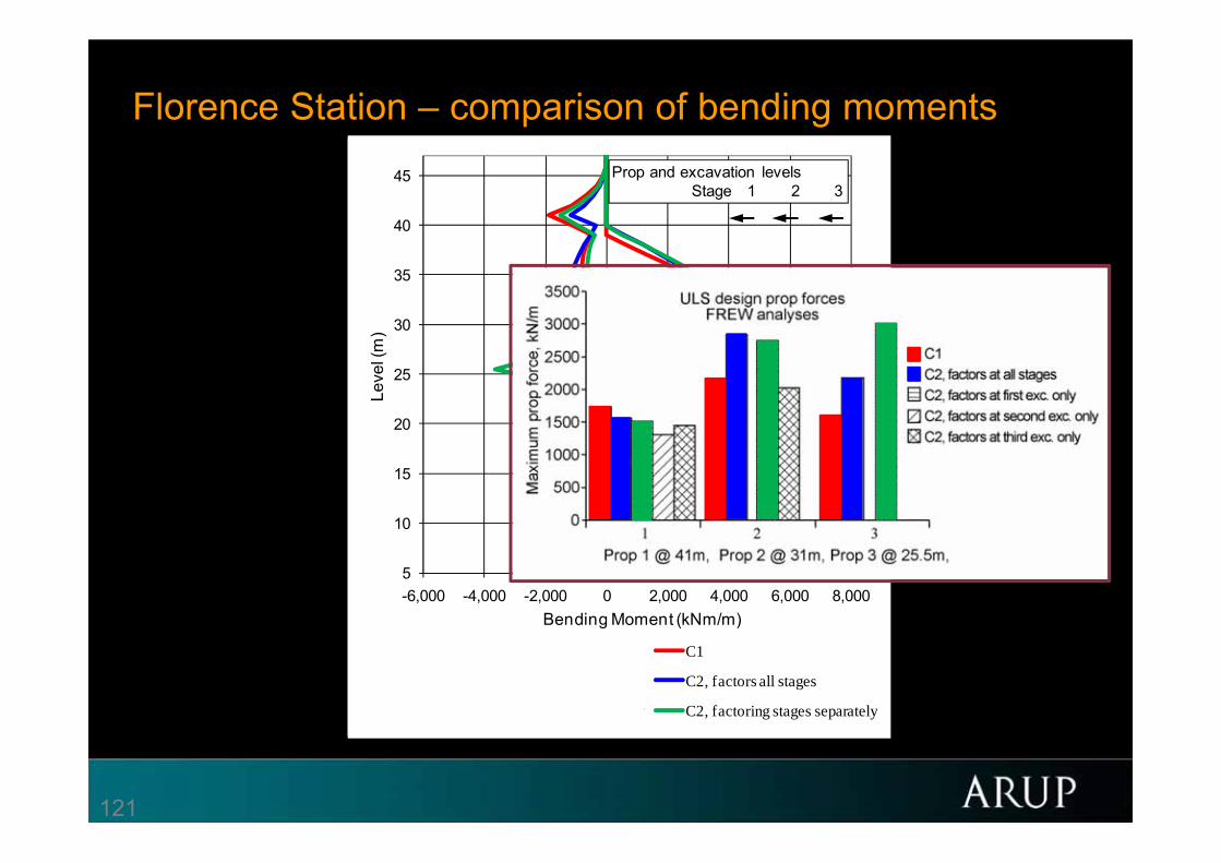
Simpson, B and Hocombe, T (2010) Implications of modern design codes for earth retaining structures. Proc ER2010, ASCE Earth Retention Conference 3, Seattle, Aug 2010.
Florence Rail Station• 25m deep, 50m wide,
550m long
• Mezzanine level prop
• High groundwater level

116
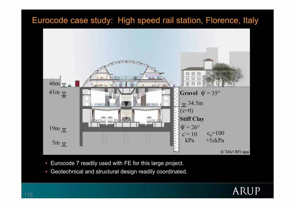
Eurocode case study: High speed rail station, Florence, Italy
• 454m long, 52m wide and 27 to 32m deep• 1.2 to 1.6m thick diaphragm walls• Three levels of temporary strutting.

117
Eurocode case study: High speed rail station, Florence, Italy
• SLS analyzed as if London Clay using the BRICK model.• Time dependent swelling and consolidation.• Eurocode 7, DA1, Combinations 1 and 2 analysed using FE and Oasys FREW.
118
Eurocode case study: High speed rail station, Florence, Italy
• Eurocode 7 readily used with FE for this large project.• Geotechnical and structural design readily coordinated.
119
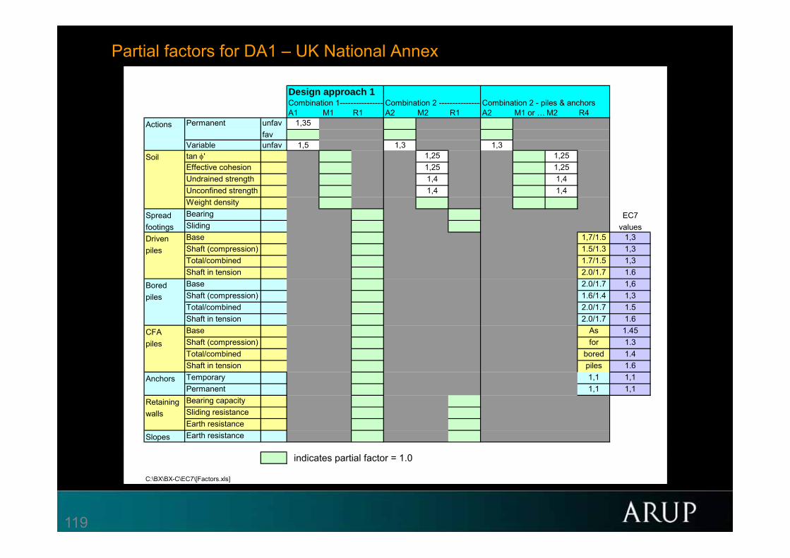
Partial factors for DA1 – UK National Annex BP111.20 BP124-T2.13 BP124-A2.11
BP143.22 BP168.82 BP188.36
Design approach 1 Combination 1---------------- Combination 2 ----------------Combination 2 - piles & anchorsA1 M1 R1 A2 M2 R1 A2 M1 or … M2 R4
Actions unfav 1,35favunfav 1,5 1,3 1,3
Soil tan ' 1,25 1,25Effective cohesion 1,25 1,25Undrained strength 1,4 1,4Unconfined strength 1,4 1,4Weight density
Spread Bearing EC7footings Sliding valuesDriven Base 1,7/1.5 1,3piles Shaft (compression) 1.5/1.3 1,3
Total/combined 1.7/1.5 1,3Shaft in tension 2.0/1.7 1.6
Bored Base 2.0/1.7 1,6piles Shaft (compression) 1.6/1.4 1,3
Total/combined 2.0/1.7 1.5Shaft in tension 2.0/1.7 1.6
CFA Base As 1.45piles Shaft (compression) for 1.3
Total/combined bored 1.4Shaft in tension piles 1.6
Anchors Temporary 1,1 1,1Permanent 1,1 1,1
Retaining Bearing capacitywalls Sliding resistance
Earth resistanceSlopes Earth resistance
indicates partial factor = 1.0
C:\BX\BX-C\EC7\[Factors.xls]
Permanent
Variable

120
ULS for staged construction – single propped excavation
Factor material strengths
Initial state
Excavate to 5m –wall cantilevering
Could be critical for wall bending moment
Install prop at 4m depth
Excavate to 10m
Could be critical for wall length, bending moment and prop force
Compute using characteristic parameters
Compute using factored parameters
Excavate to 5m –wall cantilevering
Install prop at 4m depth
Excavate to 10m
No further factors on strut forces or BMs
Compute using factored strength
Apply factors on strut forces or BMs
Compute using unfactored parameters
No further factors on strut forces or BMs
Initial state?
121
Florence Station – comparison of bending moments
5
10
15
20
25
30
35
40
45
-6,000 -4,000 -2,000 0 2,000 4,000 6,000 8,000
Leve
l (m
)
Bending Moment (kNm/m)
C1 C1
C2, factors all stages C2, factors all stages
Prop and excavation levelsStage 1 2 3
5
10
15
20
25
30
35
40
45
-6,000 -4,000 -2,000 0 2,000 4,000 6,000 8,000
Leve
l (m
)
Bending Moment (kNm/m)
C1 C1
C2, factors all stages C2, factors all stages
C2,factoring stages separately C2, factoring stages separately
Prop and excavation levelsStage 1 2 3

122
Eurocode 7 –fundamental issues and some implications for users
BP198.2 BP201.2
• Safety format of EC7
• Characteristic and design values of soil parameters
• Design in situations dominated by water pressures
• The EQU limit state
• Numerical analysis for ULS design• EG4 – Andrew Lees - Cyprus

123
Concluding remarks
• Code-drafter’s challenge: To standardise and regulate where it is sensible to do so, while encouraging maximum exploitation of engineering expertise.
• Characteristic values and water pressures: full use of human knowledge, sometimes guided but never governed by statistics.
• Partial factors: society’s safety margin (and ours!).
• FEM the tool of the future – code must not restrict.
• EC7 – still evolving!
124
Nordic Geotechnical MeetingCopenhagen, May 2012 BP198.1
BP201.1
Eurocode 7 –fundamental issues and some implications for users
Brian Simpson, Arup Geotechnics
Thanks for your attention