eng.najah.edu · Web viewIf this system is applied all around the world in schools and...
58
Transcript of eng.najah.edu · Web viewIf this system is applied all around the world in schools and...
AN-Najah National UniversityFaculty of Engineering
Electrical Engineering Department
This project submitted for requirements of Graduation project -1
RFID automated attendance system
Prepared by:Abeer Bibi
Nour Aqqad
Submitted to:Dr. Jamal Kharrousheh

Dedication : إلى من جرع الكأس فارغاً ليسقيني قطرة حب
إلى من كلّت أنامله ليقدم لنا لحظة سعادة إلى من حصد األشواك عن دربي ليمهد لي طريق العلم
إلى القلب الكبير
(والدي العزيز)
إلى من أرضعتني الحب والحنانإلى رمز الحب وبلسم الشفاء
إلى القلب الناصع بالبياض
(والدتي الحبيبة)
إلى القلوب الطاهرة الرقيقة والنفوس البريئة إلى رياحين حياتي
(إخوتي)
إلى األساتذة الكرام في كلية الهندسة ونتوجه بالشكر الجزيل إلى
الدكتور (جمال خروشة)
الذي تفضل بإشراف على هذا البحث فجزاه الله عنا كل خيرفله منا كل التقدير واالحترام
Acknowledgment:
We have taken effort at this project . However , it would not have been possible without the help and support of many persons. We would like to extend my sincere thanks to all.

First , we would like to express our grateful to Allah , who gives us the faith and patience all the time. Also we would like to express our gratitude towards our parents for their extra support and encouragement since we were a child until now and they did everything that they can do for us.
Second , we would like to show our greatest appreciations to our supervisor Dr. Jamal Kharrousheh . we can't say thank you only, it's not enough for his tremendous support and help. Without his encouragement , this project would not have materialized.
Finally, we would like to express our love to who was beside us along this year. Our appreciations also go to our colleagues and people who had helped us with their abilities.
ABSTRACTThis project is developed by using Radio Frequency Identification (RFID)
system and student card to get student attendance. Before this lecturer needs to use
the paper to get the student attendance. There were a lot of problems when using the
paper as student attendance such as cheating. This project can help lecturer to reduce
the problem like that by design automatic attendance using RFID and student card.
The project system was running by get the code of card student to compare with the
database in Access. Firstly, lecturer needs to fill forms in
an interface like lecturer name, subject and code subject. This part is important
because we need the information in this part to use in the next interface. In the next
interface, lecturer needs to choose port and speed to make connection with RFID
reader. After the reader was ready, process to get attendant will started. Students
need to swap their card on the reader and the code from the card will use to compare
with database in Access. When the code is match with database, the student
information like name and ID number will show on interface and that information
will trigger into a list. This list will use as a student attendance. In that list, all
information like student name and ID number will attached including the lecturer
name and subject. If the code were not match with database, it means that student
was in the wrong class or not registers yet in that subject. When this happen, lecturer
can register that student by using registering form and the information of that student
will be update into database. This project will help lecturer taking the student
attendance more easily and automatically. As the conclusion, RFID technology can
be used in student attendance application.
Table of Contents :
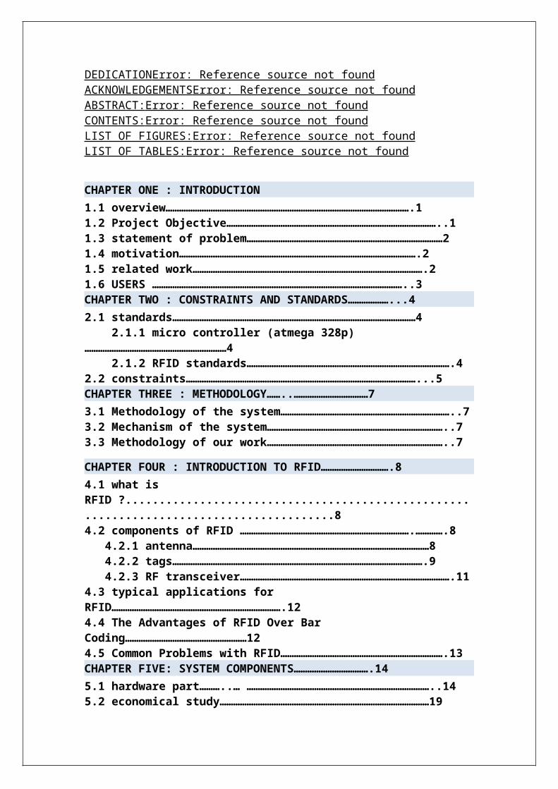
DEDICATION Error: Reference source not found ACKNOWLEDGEMENTS Error: Reference source not found ABSTRACT: Error: Reference source not found CONTENTS: Error: Reference source not found LIST OF FIGURES: Error: Reference source not found LIST OF TABLES: Error: Reference source not found
CHAPTER ONE : INTRODUCTION
1.1 overview……………………………………………………………………………………………….11.2 Project Objective…………………………………………………………………………………..11.3 statement of problem……………………………………………………………………………21.4 motivation…………………………………………………………………………………………….21.5 related work………………………………………………………………………………………….21.6 USERS …………………………………………………………………………………………………..3CHAPTER TWO : CONSTRAINTS AND STANDARDS………………...42.1 standards………………………………………………………………………………………………4 2.1.1 micro controller (atmega 328p)………………………………………………………4 2.1.2 RFID standards……………………………………………………………………………….42.2 constraints…………………………………………………………………………………………...5CHAPTER THREE : METHODOLOGY……..……………………………73.1 Methodology of the system…………………………………………………………………..73.2 Mechanism of the system……………………………………………………………………..73.3 Methodology of our work……………………………………………………………………..7
CHAPTER FOUR : INTRODUCTION TO RFID………………………….84.1 what is RFID ?........................................................................................84.2 components of RFID ………………………………………………………………….………….8 4.2.1 antenna……………………………………………………………………………………………8 4.2.2 tags………………………………………………………………………………………………….9 4.2.3 RF transceiver………………………………………………………………………………….114.3 typical applications for RFID………………………………………………………………….124.4 The Advantages of RFID Over Bar Coding………………………………………………124.5 Common Problems with RFID……………………………………………………………….13CHAPTER FIVE: SYSTEM COMPONENTS…………………………….145.1 hardware part………..… ………………………………………………………………………..145.2 economical study…………………………………………………………………………………195.3software part………………………….............................................................205.4system requirements…………………………………………………………………………….215.5work flow of the system………………………………………………………………………..22CHAPTER SIX: RESULTS AND ANALYSIS…………………………….23
CHAPTER SEVEN:DISCUSSION………………………………………….24
CHAPTER EIGHT: FUTURE WORK……………………………………...25CHAPTER NINE: CONCLUSION AND RECOMMENDATIONS…………269.1 conclusion………………………………………………………………………………………………….269.2 recommendations………………………………………………………………………………………26REFERENCES……………………………………………………………………27ATTACHMENT A………………………………………………………………..28APPENDIX B……………………………………………………………………...29
list of tables :table 2.1 comparison between RFID sys.&other sys…………………………………..5
table 4.1 advantages of RFID over bar coding…………………………………………….12
table 5.1 pin out of LCD………………………………………………………………………………19
table 5.2 cost of components……………………………………………………………………..20
list of figures:fig3.1 methodology of our work…………………………………………………………………7
fig4.1 antenna of RFID………………………………………………………………………………..9
fig4.2 RFID tag…………………………………………………………………………………………….10
fig5.1 system components………………………………………………………………………….14
Fig5.2 power supply……………………………………………………………………………………15
Fig5.3 Block diagram of argulated power supply system…………………………….15
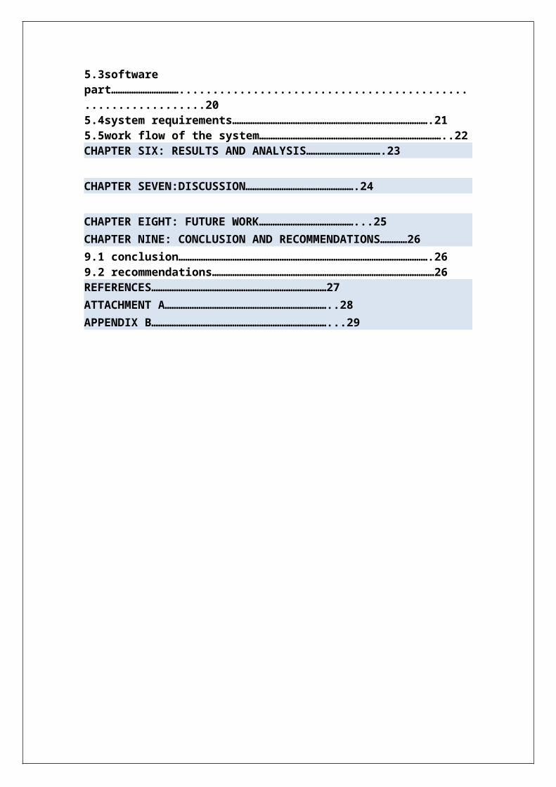
Fig5.4 simplified view of data transfer in low freq. passive RFID tag………….16
Fig5.5 RFID reader……………………………………………………………………………………..16
Fig5.6 RFID card…………………………………………………………………………………………17
Fig5.7 ATmega328p Datasheet…………………………………………………………………..18
Fig5.8 atmega328p…………………………………………………………………………………….18
Fig5.9 keypad interface with arduino…………………………………………………………19
Fig5.10 interface 16*2 lcd with arduino……………………………………………………..20
Fig5.11 flow chart of the system…………………………………………………………………23
Fig6.1 serial number of the card…………………………………………………………………24
Fig6.2 connection of RFID reader with arduino…………………………………………..24
Fig7.1 illustration of the RFID system operational principle………………………..25
CHAPTER ONE: INTRODUCTION
This chapter will briefly discuss the project overview.
1.1 overview
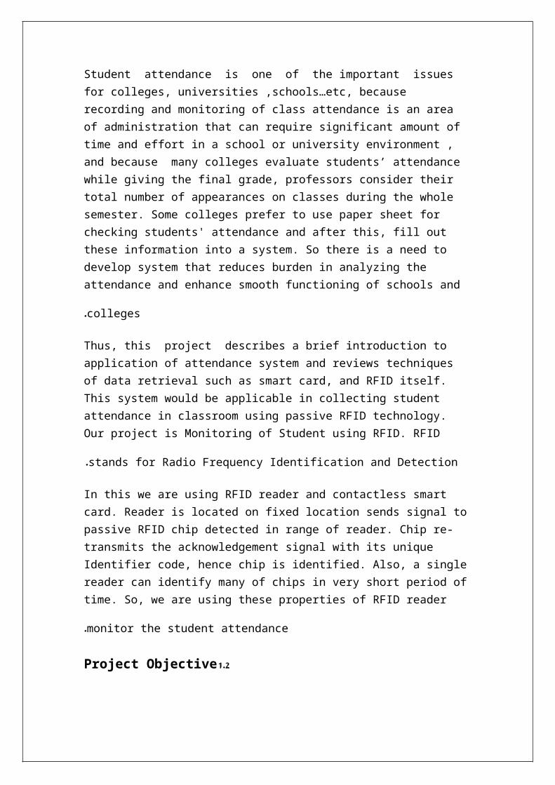
Student attendance is one of the important issues for colleges, universities ,schools…etc, because recording and monitoring of class attendance is an area of administration that can require significant amount of time and effort in a school or university environment , and because many colleges evaluate students’ attendance while giving the final grade, professors consider their total number of
appearances on classes during the whole semester. Some colleges prefer to use paper sheet for checking students' attendance and after this, fill out these information into a system. So there is a need to develop system that reduces burden in analyzing the attendance and enhance smooth functioning of schools and colleges.
Thus, this project describes a brief introduction to application of attendance system and reviews techniques of data retrieval such as smart card, and RFID itself. This system would be applicable in collecting student attendance in classroom using passive RFID technology. Our project is Monitoring of Student using RFID. RFID stands for Radio Frequency Identification and Detection .
In this we are using RFID reader and contactless smart card. Reader is located on fixed location sends signal to passive RFID chip detected in range of reader. Chip re-transmits the acknowledgement signal with its unique Identifier code, hence chip is identified. Also, a single reader can identify many of chips in very short period of time. So, we are using these properties of RFID reader monitor the student attendance.
1.2 Project Objective
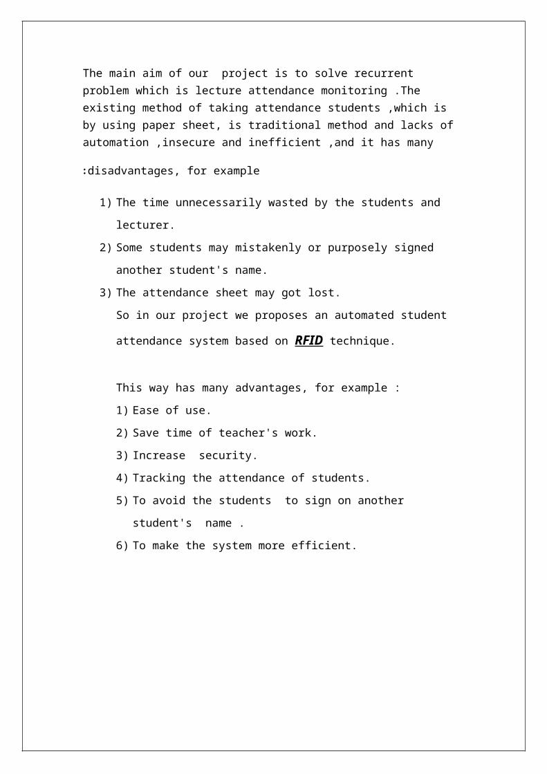
The main aim of our project is to solve recurrent problem which is lecture attendance monitoring .The existing method of taking attendance students ,which is by using paper sheet, is traditional method and lacks of automation ,insecure and
inefficient ,and it has many disadvantages, for example:
1) The time unnecessarily wasted by the students and lecturer.
2) Some students may mistakenly or purposely signed another student's name.
3) The attendance sheet may got lost.
So in our project we proposes an automated student attendance system based
on RFID technique.
This way has many advantages, for example :
1) Ease of use.
2) Save time of teacher's work.
3) Increase security.
4) Tracking the attendance of students.
5) To avoid the students to sign on another student's name .
6) To make the system more efficient.
1.3 statement of problem
Currently the method that companies use to control the flow of people coming in and out is very lacking. People (employees or outsiders) can go in and out of the company’s premises with minimal supervision. Important records such as picture and time of entry or exit are not properly managed or recorded. The attendance system also has the absolute potential of wasting valuable time since the employees need to line up and wait their turn to tally up hand-written time cards or punch clock cards manually.
1.4 motivation
This project began with the research of the proposed title. The result of that research
was then discussed with the supervisor. Once we had agreed with the supervisor on
the title, the background study of this project was searched.
When the project has progressed thus far, the process of designing the system could
be done. Components now could be chosen and the control elements programmed
using the desired software. The correct software is chosen to comply with the control
elements.
1.5 related work
The use of Radio-frequency identification (RFID) technology in automated electronic environment and for tracking objects has been widely researched upon by researchers and deployed by various organizations as part of their automation systems. RFID is a technology that uses radio waves to transfer data from an electronic tag, called RFID tag or label, attached to an object, through a reader for the purpose of identifying and tracking the object. In 1945, Leon Theremin invented an espionage tool (for spy activities) for the Soviet Union which retransmitted incident radio waves with audio frequency information.
Sound waves vibrated a diaphragm which slightly altered the shape of the resonator, which modulated the reflected radio frequency even though this device was covert listening device, not an identification device or tag, it is considered to be a predecessor of radio frequency identification (RFID) technology because it was likewise passive, being energized and activated by waves from an outside source.
Similar technologies such as the IFF (identification friend and foe) transponder developed in the United Kingdom, was routinely used by the allies in the World War 2 to identify aircrafts as friend or foe. Transponders are still used by most powered aircrafts to this day.
Mario .W. Cardullo was the first to have received the United States patent for an active RFID tag with re-writable memory on January 23, 1973 . In that same year,

Charles Walton, a California entrepreneur, received a patent for a passive transponder used to unlock a door without a key.
A card with an embedded transponder communicates a reader near a door, when the reader detects a valid identification number stored within the tag, the reader unlocks the door. Time and attendance systems are a major part of today’s human resource systems, take organization towards better human resource practice, systems and excellence.
The implementation of time and attendance system has a lot of advantages for the manager. The kind of system that is implemented depends upon what the organization is trying to achieve by implementing the system.
There are different types of automatic attendance systems; each type of system is suited to different needs and requirements .Some of the most common types include; biometric attendance system, magnetic stripe attendance system, barcode attendance system, and RFID attendance system.
1.6 USERS :The product can be used by many organizations like our college itself. Whereby the traditional system of signing in the musters will now be replaced and replaced well by using tags allotted to the staff. However the current user is a small California startup called InCom has developed a radio frequency identification (RFID) system called InClass to automate attendance-taking in elementary and secondary schools. The system uses ultra-high frequency (UHF) readers mounted in classroom doorways and passive RFID tags attached to student ID card holders. A unique 15-digit ID number is written to each tag and associated with the name of the student to whom it is issued. As the students pass through the reader-generated interrogation field under a doorway, the reader sends the tags' unique ID numbers to a central server. InCom has developed a software program, installed on the server, that collects the tag data and uploads a list of present, absent and tardy (based on when they enter the classroom) students to a PDA that is issued to the teacher.
CHAPTER TWO : standards and constraints
2.1 standardsWe have many standards like:
2.1.1 Microcontroller (ATmega328P):
The high-performance Atmel Pico power 8-bit reduced instruction set
computing (RISC)based micro controller combines 32KB ISP flash memory with read-while-write capabilities, 1024B EEPROM, 2KB SRAM, 23 general purpose Input/output lines, 32 general purpose working registers, three flexible timer/counters with compare modes, internal and external interrupts, a 6-channel 10-bit Analog/Digital converter, programmable watchdog timer with internal oscillator, and five software selectable power saving modes. The device operates between 1.8-5.5 volts. Simple-to-use, low cost yet powerful programmer for the ATMEL 8051 family of micro controllers. It will Program, Read and Verify Code Data, Write Lock Bits, Erase and Blank Check.By executing powerful instructions in a single clock cycle, the device achieves throughputs approaching 1 MIPS per MHz, balancing power consumption and processing speed .
2.1.2RFID: RFID Standard as apply to frequency :
At low frequency (LF) 125/134 KHZ :
International Standards Organization (ISO 11784) . International Standards Organization/ International Electrotechnical
Commission (ISO/IEC 18000-2A).( ISO/IEC 18000-2B[ )21.]
2.2 constraints
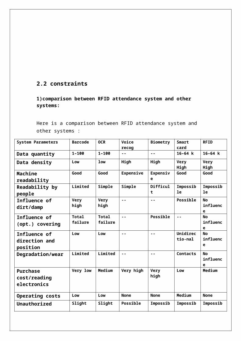
1)comparison between RFID attendance system and other systems:
Here is a comparison between RFID attendance system and other systems :
System Parameters Barcode OCR Voice recog Biometry Smart card RFID
Data quantity 1–100 1–100 -- -- 16–64 k 16–64 k
Data density Low low High High Very High Very High
Machine readability Good Good Expensive Expensive Good Good
Readability by people Limited Simple Simple Difficult Impossible Impossible
Influence of dirt/damp
Very high Very high -- -- Possible No influence
Influence of (opt.) covering
Total failure
Total failure
-- Possible -- No influence
Influence of direction and position
Low Low -- -- Unidirectio-nal
No influence
Degradation/wear Limited Limited -- -- Contacts No influence
Purchase cost/reading electronics
Very low Medium Very high Very high Low Medium
Operating costs Low Low None None Medium None
Unauthorized copying/modification
Slight Slight Possible (audio tape)
Impossible Impossible Impossible
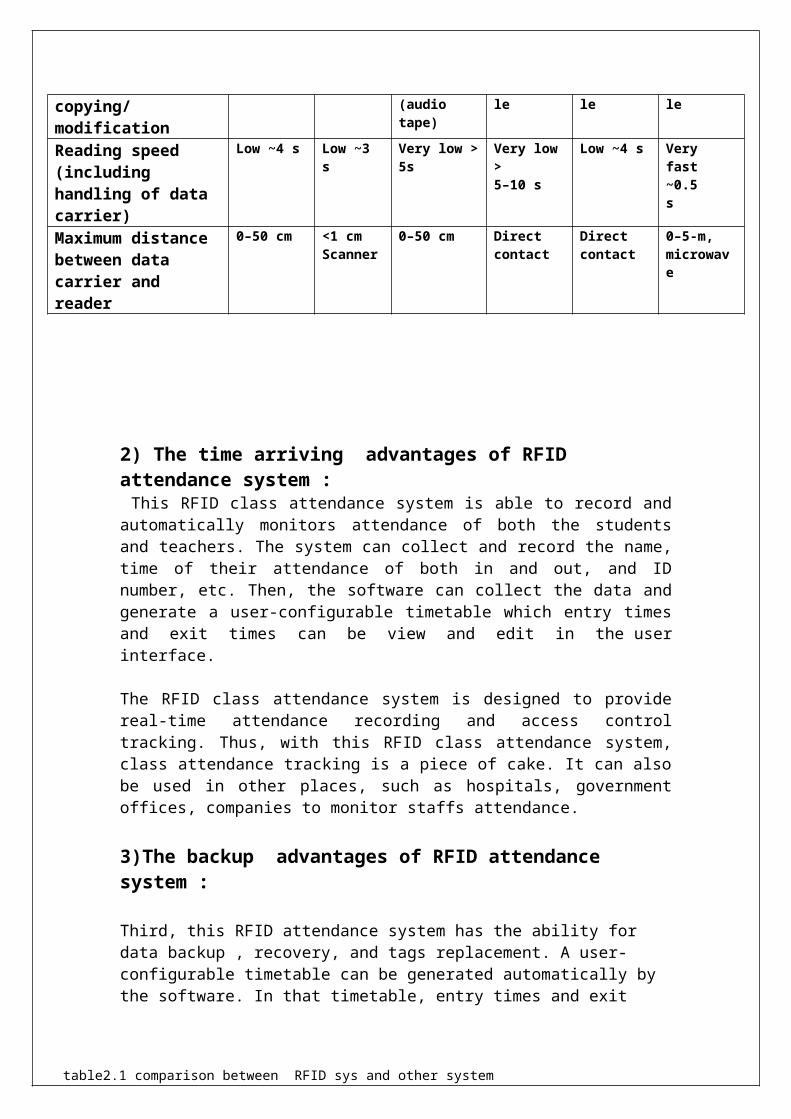
Reading speed (including handling of data carrier)
Low ~4 s Low ~3 s Very low > 5s
Very low > 5–10 s
Low ~4 s Very fast ~0.5 s
Maximum distance between data carrier and reader
0–50 cm <1 cm Scanner
0–50 cm Direct contact
Direct contact
0–5-m, microwave
2) The time arriving advantages of RFID attendance system : This RFID class attendance system is able to record and automatically monitors attendance of both the students and teachers. The system can collect and record the name, time of their attendance of both in and out, and ID number, etc. Then, the software can collect the data and generate a user-configurable timetable which entry times and exit times can be view and edit in the user interface. The RFID class attendance system is designed to provide real-time attendance recording and access control tracking. Thus, with this RFID class attendance system,
table2.1 comparison between RFID sys and other system
class attendance tracking is a piece of cake. It can also be used in other places, such as hospitals, government offices, companies to monitor staffs attendance.
3)The backup advantages of RFID attendance system :
Third, this RFID attendance system has the ability for data backup , recovery, and tags replacement. A user-configurable timetable can be generated automatically by the software. In that timetable, entry times and exit times can be view and edit in the user interface, which gives high reliability with low maintenance cost.
4) The environmental advantages of RFID attendance system :The design of student attendance system based on RFID has significant reality meaning. The system not only can improve the work efficiency, students’ study and development, but also can save human and material resources.If this system is applied in schools& universities all around the world, it will save a huge amount of paper and so reduce trees cutting .
It will also reduce the pollution due to the decrease in paper factories .
5) The economical advantages of RFID attendance system :
If this system is applied all around the world in schools and universities, it will reduce the cost of papers or sheets that is needed in each semester and for each class to take the attendance in the traditional way, because every teacher will own one device which its data could be changed at any time by software, so this device will last many years, so there will be no need for a paper sheet for every semester or for every class for the same teacher.
CHAPTER THREE: 3.1 Methodology of the system: The complete RFID system comprises of four main parts:
1) RFID tags.
2) RFID readers.
3) Computer host.
4) Database
3.2 The mechanism of the system:Lecturer :get the students attendance automatically by using RFID hardware
device and have a full report saved in the database about whole students
which help to evaluate the student depending on his attendance record rapidly
.
Students: using contactless smart cards (tag) and register his attendance
automatically , without need to write his name on the paper.
RFID device : is a hardware that get the signal for student tag and send it to
the pc , after that the software receives the student identity number (ID ) and
add it to the database with attendance time.
3.3 methodology of our work:
fig.3.1 methodology of our work
CHAPTER FOUR :INTRODUCTION TO RFID
4.1 what is RFID ?
Radio-frequency identification (RFID) is an automatic identification method, relying on storing and remotely retrieving data using devices called RFID tags or transponders. The technology requires some extent of cooperation of an RFID reader and an RFID tag.
An RFID tag is an object that can be applied to or incorporated into a product, animal, or person for the purpose of identification and tracking using radio waves.
Some tags can be read from several meters away and beyond the line of sight of the reader.
A basic RFID system consists of three components: a) An antenna or coil b) A transceiver (with decoder) c) A transponder (RF tag)
Electronically programmed with unique information. There are many different types of RFID systems out in the market. They are categorized according to their frequency
ranges. Some of the most commonly used RFID kits are as follows: 1) Low-frequency (30 KHz to 500 KHz( 2)Mid-Frequency (900KHz to 1500MHz(3) High Frequency (2.4GHz to 2.5GHz)
Radio Frequency Identification (RFID) is an automatic identification method, relying on storing and remotely retrieving data using devices called RFID tags or transponders. So the
RFID is a wireless identification .
These frequency ranges mostly tell the RF ranges of the tags from low frequency tag ranging from 3m to 5m, mid frequency ranging from 5m to 17m and high frequencyranging from 5ft to 90ft. The cost of the system is based according to their ranges with low-frequency system ranging from a few hundred dollars to a high-frequency system ranging somewhere near 5000 dollars.
4.2 components of RFID
4.2.1.antennaThe antenna emits radio signals to activate the tag and read and write data to it. Antennas are the conduits between the tag and the transceiver, which controls the system's data acquisition and communication. Antennas are available in a variety of shapes and sizes; they can be built into a doorframe to receive tag data from persons or things passing through the door, or mounted on an interstate tollbooth to monitor traffic passing by on a freeway. The electromagnetic field produced by an antenna can beconstantly present when multiple tags are expected continually. If constant interrogation is not required, a sensor device can activate the field.Often the antenna is packaged with the transceiver and decoder to become a reader (a.k.a. interrogator), which can be configured either as a handheld or a fixed-mount device.
The reader emits radio waves in ranges of anywhere from one inch to 100 feet or more, depending upon its power output and the radio frequency used. When an RFID tag passes through the electromagnetic zone, it detects thereader's activation signal. The reader decodes the data encoded in the tag's integrated circuit (silicon chip) and the data is passed to the host computer for processing.
fig.4.1 antenna of RFID
4.2.2 tags (transponders)
An RFID tag is comprised of a microchip containing identifying information and an antenna that transmits this data wirelessly to a reader. At its most basic, the chip will contain a serialized identifier, or license plate number, that uniquely identifies that item, similar to the way many bar codes are used today. A key difference, however is that RFID tags have a higher datacapacity than their bar code counterparts. This increases the options for the type of information that can be encoded on the tag, including the manufacturer, batch or lot number, weight, ownership, destination and history (such as the temperature range to which an item has been exposed). In fact, an unlimited list of other types of information can be stored on RFID tags, depending on application needs. An RFID tag can be placed on individual items, cases or pallets for identification purposes, as well as on fixed assets such as trailers, containers, totes, etc.Tags come in a variety of types, with a variety of capabilities. Key variables include: "Read-only" versus "read-write"
There are three options in terms of how data can be
encoded on tags:
(1) Read-only tags contain data such as a serialized tracking number, which is pre-written onto them by the tag manufacturer or distributor. These are generally the least expensive tags because they cannot have any additional information included as they move throughout the supply chain. Any updates to that information would have to be maintained in the application software
(2) "Write once" tags enable a user to write data to the tag one time in production or distribution processes. Again, this may include a serial number, but perhaps other such as a lot ar patch number
(3) Full "read-write" tags allow new data to be written to the tag as needed—and even written over the original data. Examples for the latter capability might include the time and date of ownership transfer or updating the repair history of a fixed asset. While these are the most costly of the three tag types and are not practical for tracking inexpensive items, future standards for electronic product codes (EPC) appear to be headed in this direction.
fig.4.2 RFID tag 1
DATA CAPACITYThe amount of data storage on a tag can vary, ranging from 16 bits on the low end to as much as several thousand bits on the high end. Of course, the greater the storage capacity, the higher the price per tag.
FORM FACTORThe tag and antenna structure can come in a variety of physical form factors and can either be self-contained or embedded as part of a traditional label structure . companies must choose the appropriate form factors for the tag very carefully and should expect to use multiple form factors to suit thetagging needs of different physical products and units ofmeasure.(Form factor: if we want to use the same card for different uses).
PASSIVE VERSUS ACTIVE
“Passive” tags have no battery and "broadcast" their data only when energized by a reader. That means they must be actively polled to send information. "Active" tags are capable of broadcasting their data using their own battery power. In general, this means that the read ranges are much
greater for active tags than they are for passive tags—perhaps a read range of 100 feet or more, versus 15 feet or less for most passive tags. The extra capability and read ranges of active tags, however, come with a cost; they are several times more expensive than passive tags. Today, active tags are much more likely to be used for high-value items or fixed assets such as trailers, where the cost is minimal compared to item value, and very long read ranges are required. Most traditional supply chain applications, such as the RFID-based tracking and compliance programsemerging in the consumer goods retail chain, will use the less expensive passive tags.
FREQUENCIESLike all wireless communications, there are a variety of frequencies or spectra through which RFID tags can communicate with readers. Again, there are trade-offs among cost, performance and application requirements. For instance, low-frequency tags are cheaper than ultra high frequency(UHF) tags, use less power and are better able to penetrate non-metallic substances. They are ideal for scanning objects with high water content, such as fruit, atclose range. UHF frequencies typically offer better range and can transfer data faster. But they use more power and are less likely to pass through some materials. UHF tags are typically best suited for use with or near wood, paper, cardboard or clothing products. Compared to low frequency tags, UHF tags might be better for scanningboxes of goods as they pass through a bay door into a warehouse. While the tag requirements for compliance mandates may be narrowly defined, it is likely that a variety of tag types will be required to solve specificoperational issues. You will want to work with a company that is very knowledgeable in tag and reader technology to appropriately identify the right mix of RFID technology for your environment and applications.
4.2.3 RF TRANSCEIVER:The RF transceiver is the source of the RF energy used to activate and power the passive RFID tags. The RF transceiver may be enclosed in the same cabinet as the reader or it may be a separate piece of equipment. Whenprovided as a separate piece of equipment, the transceiver is commonly referred to as an RF module. The RF transceiver controls and modulates the radio frequencies that the antenna transmits and receives. The transceiverfilters and amplifies the backscatter signal from a passive RFID tag.
4.3 typical applications for RFID :
Automatic Vehicle identification. Inventory Management. Work-in-Process.. Document/ Jewellery tracking. Patient Monitoring.
4.4 The Advantages of RFID Over Bar Coding:
1. No "line of sight" requirements: Bar code reads can sometimes be limited or problematic due to the need to have a direct "line of sight" between ascanner and a bar code. RFID tags can be read through materials without line of sight.
2. More automated reading: RFID tags can be read automatically when a tagged product comes past or near a reader, reducing the labor required toscan product and allowing more proactive, real-time tracking.
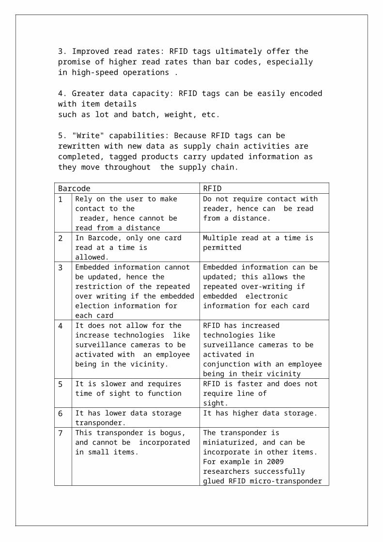
3. Improved read rates: RFID tags ultimately offer the promise of higher read rates than bar codes, especially in high-speed operations .
4. Greater data capacity: RFID tags can be easily encoded with item detailssuch as lot and batch, weight, etc.
5. "Write" capabilities: Because RFID tags can be rewritten with new data as supply chain activities are completed, tagged products carry updated information as they move throughout the supply chain.
Barcode RFID1 Rely on the user to make contact to the
reader, hence cannot be read from a distance
Do not require contact with reader, hence can be read from a distance.
2 In Barcode, only one card read at a time is allowed.
Multiple read at a time is permitted
3 Embedded information cannot be updated, hence the restriction of the repeated over writing if the embedded election information for each card
Embedded information can be updated; this allows the repeated over-writing if embedded electronic information for each card
4 It does not allow for the increase technologies like surveillance cameras to be activated with an employee being in the vicinity.
RFID has increased technologies like surveillance cameras to be activated in conjunction with an employee being in their vicinity
5 It is slower and requires time of sight to function
RFID is faster and does not require line of sight.
6 It has lower data storage transponder. It has higher data storage. 7 This transponder is bogus, and cannot be
incorporated in small items. The transponder is miniaturized, and can be incorporate in other items. For example in 2009 researchers successfully glued RFID micro-transponder to live ants.micro-transponder to live ants
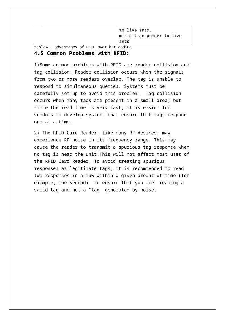
table4.1 advantages of RFID over bar coding4.5 Common Problems with RFID:
1)Some common problems with RFID are reader collision and tag collision. Reader collision occurs when the signals from two or more readers overlap. The tag is unable to respond to simultaneous queries. Systems must be carefully set up to avoid this problem. Tag collision occurs when many tags are present in a small area; but since the read time is very fast, it is easier for vendors to develop systems that ensure that tags respond one at a time.
2) The RFID Card Reader, like many RF devices, may experience RF noise in its frequency range. This may cause the reader to transmit a spurious tag response when no tag is near the unit.This will not affect most uses of the RFID Card Reader. To avoid treating spurious responses as legitimate tags, it is recommended to read two responses in a row within a given amount of time (for example, one second) to ensure that you are reading a valid tag and not a “tag” generated by noise.
CHAPTER FIVE : SYSTEM COMPONENTS
5.1hardware part :
It contains following block :
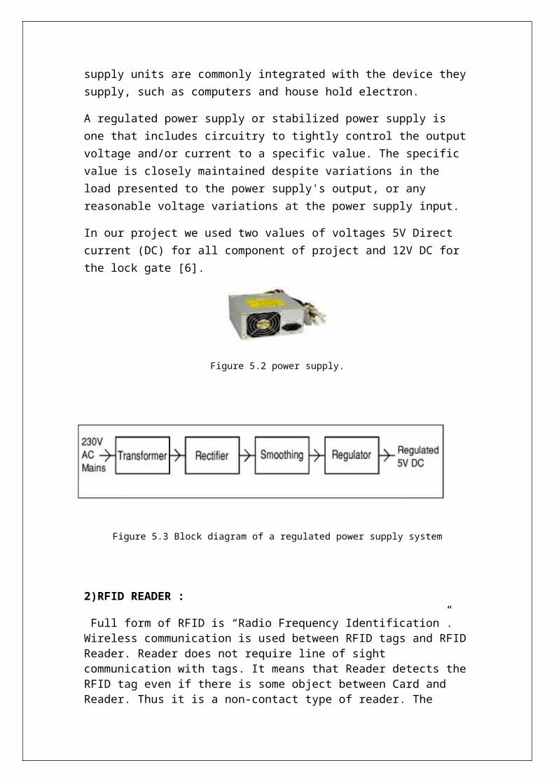
1) Power supply This is a device or system that supplies electrical or other types of energy to an output load or group of loads is called power supply unit (PSU) as shown in Fig 2.2.
The term is most commonly applied to electrical energy supplies, less often to mechanical ones, and rarely to others.
A power supply may include a power distribution system as well as primary or secondary sources of energy.
Conversion of one form of electrical power to another desired form and voltage, typically involving a converting AC line voltage to a well regulated lower-voltage DC for electronics device. Low power DC power supply units are commonly integrated with the device they supply, such as computers and house hold electron.
A regulated power supply or stabilized power supply is one that includes circuitry to tightly control the output voltage and/or current to a specific value. The specific value is closely maintained despite variations in the load presented to the power supply's output, or any reasonable voltage variations at the power supply input.
In our project we used two values of voltages 5V Direct current (DC) for all component of project and 12V DC for the lock gate [6].
Figure 5.2 power supply.
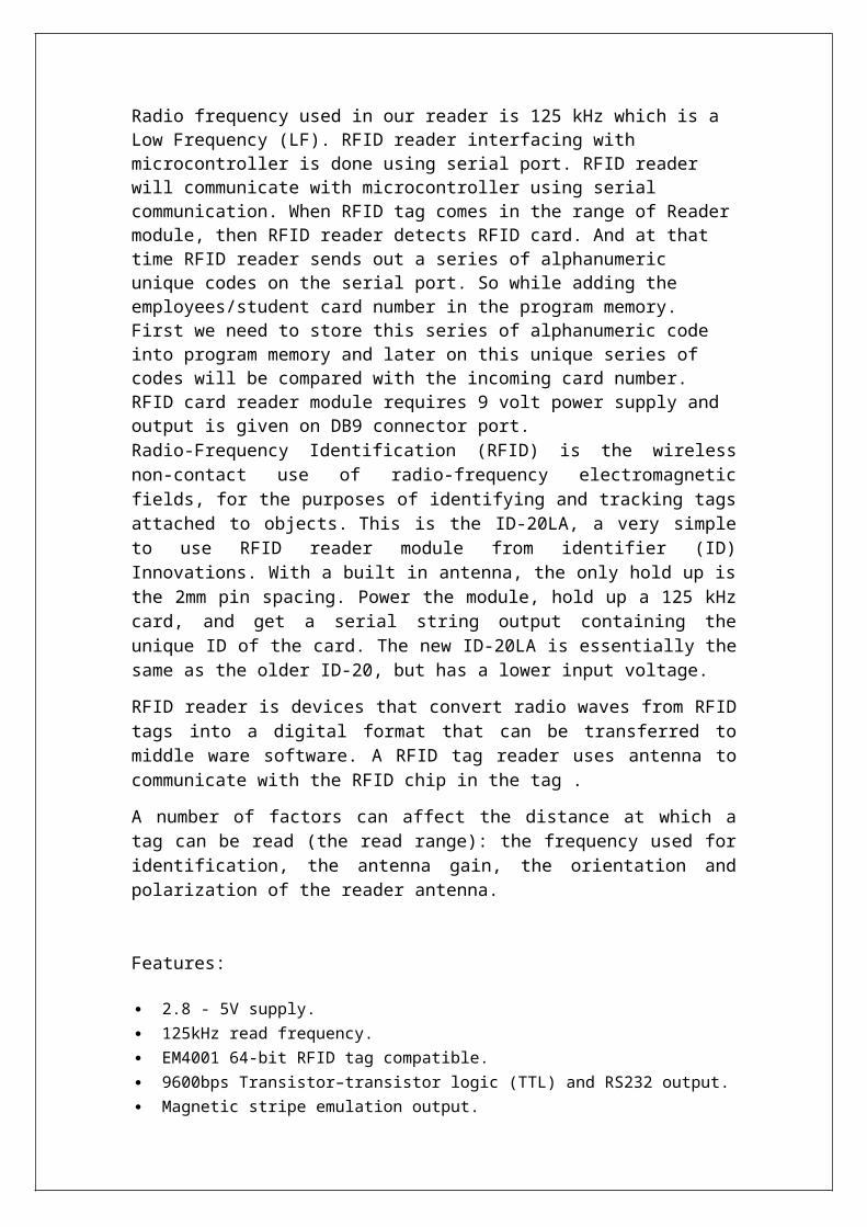
Figure 5.3 Block diagram of a regulated power supply system
2)RFID READER :
Full form of RFID is “Radio Frequency Identification”. Wireless communication is used between RFID tags and RFID Reader. Reader does not require line of sight communication with tags. It means that Reader detects the RFID tag even if there is some object between Card and Reader. Thus it is a non-contact type of reader. The Radio frequency used in our reader is 125 kHz which is a Low Frequency (LF). RFID reader interfacing with microcontroller is done using serial port. RFID reader will communicate with microcontroller using serial communication. When RFID tag comes in the range of Reader module, then RFID reader detects RFID card. And at that time RFID reader sends out a series of alphanumeric unique codes on the serial port. So while adding the employees/student card number in the program memory. First we need to store this series of alphanumeric code into program memory and later on this unique series of codes will be compared with the incoming card number. RFID card reader module requires 9 volt power supply and output is given on DB9 connector port. Radio-Frequency Identification (RFID) is the wireless non-contact use of radio-frequency electromagnetic fields, for the purposes of identifying and tracking tags attached to objects. This is the ID-20LA, a very simple to use RFID reader module from identifier (ID) Innovations. With a built in antenna, the only hold up is the 2mm pin spacing. Power the module, hold up a 125 kHz card, and get a serial string output containing the unique ID of the card. The new ID-20LA is essentially the same as the older ID-20, but has a lower input voltage.
RFID reader is devices that convert radio waves from RFID tags into a digital format that can be transferred to middle ware software. A RFID tag reader uses antenna to communicate with the RFID chip in the tag .
A number of factors can affect the distance at which a tag can be read (the read range): the frequency used for identification, the antenna gain, the orientation and polarization of the reader antenna.
Features:
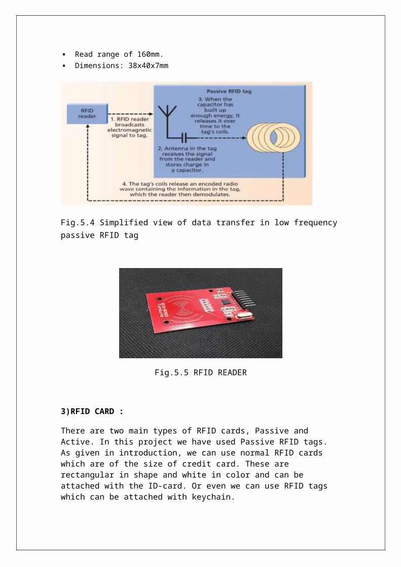
2.8 - 5V supply. 125kHz read frequency. EM4001 64-bit RFID tag compatible. 9600bps Transistor–transistor logic (TTL) and RS232 output. Magnetic stripe emulation output. Read range of 160mm. Dimensions: 38x40x7mm
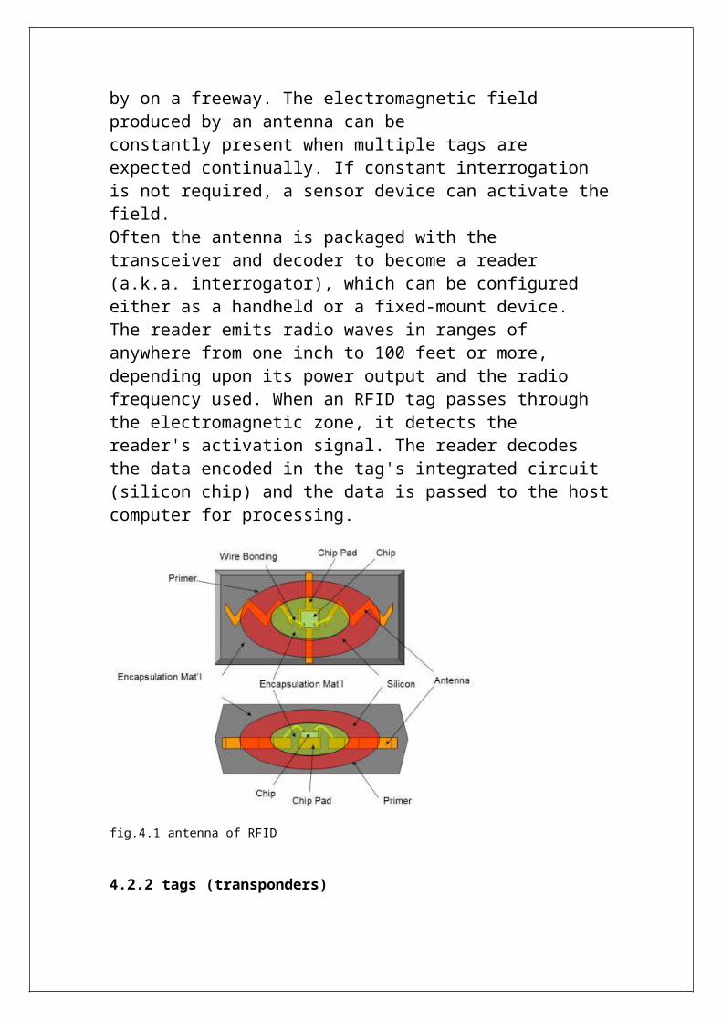
Fig.5.4 Simplified view of data transfer in low frequency passive RFID tag
Fig.5.5 RFID READER
3)RFID CARD :
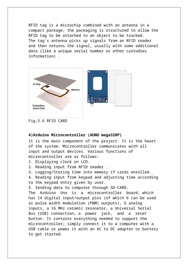
There are two main types of RFID cards, Passive and Active. In this project we have used Passive RFID tags. As given in introduction, we can use normal RFID cards which are of the size of credit card. These are rectangular in shape and white in color and can be attached with the ID-card. Or even we can use RFID tags which can be attached with keychain.RFID tag is a microchip combined with an antenna in a compact package; the packaging is structured to allow the RFID tag to be attached to an object to be tracked.The tag's antenna picks up signals from an RFID reader and then returns the signal, usually with some additional data (like a unique serial number or other custodies information) .
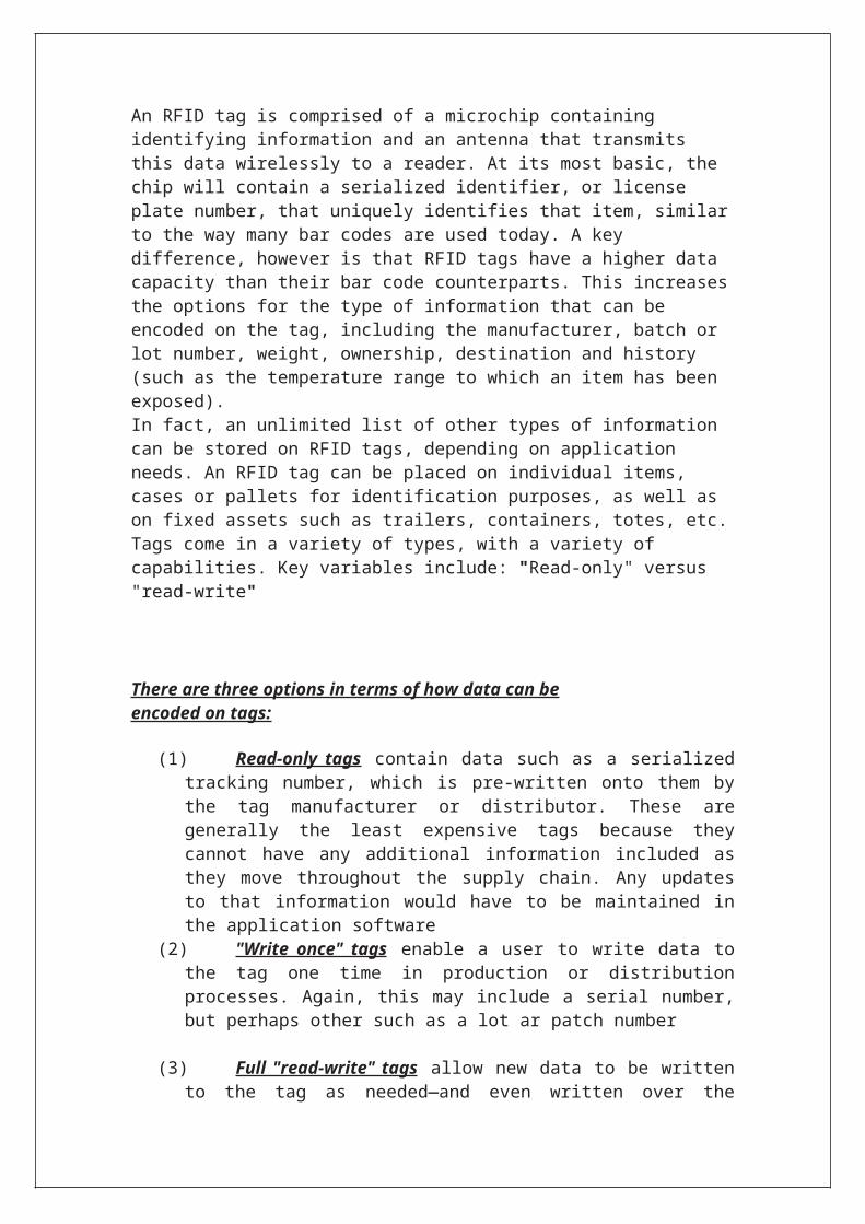
Fig.5.6 RFID CARD
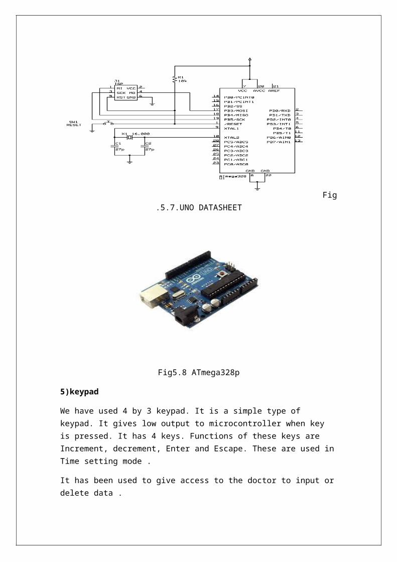
4)Arduino Microcontroller (AUNO mega328P)It is the main component of the project. It is the heart of the system. Microcontroller communicates with all input and output devices. Various functions of microcontroller are as follows:1. Displaying clock on LCD.2. Reading input from RFID reader .3. Logging/Storing time into memory if cards enrolled.4. Reading input from keypad and adjusting time according to the keypad entry given by user.5. Sending data to computer through SD-CARD.The Arduino Uno is a microcontroller board, which has 14 digital input/output pins (of which 6 can be used as pulse width modulation (PWM) outputs), 6 analog inputs, a 16 MHz ceramic resonator, a Universal Serial Bus (USB) connection, a power jack, and a reset button. It contains everything needed to support the microcontroller; simply connect it to a computer with a USB cable or power it with an AC to DC adapter or battery to get started.
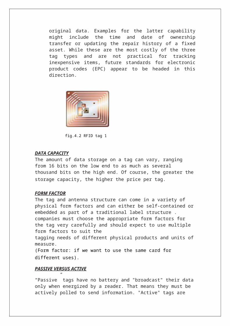
Fig.5.7.UNO DATASHEET
Fig5.8 ATmega328p
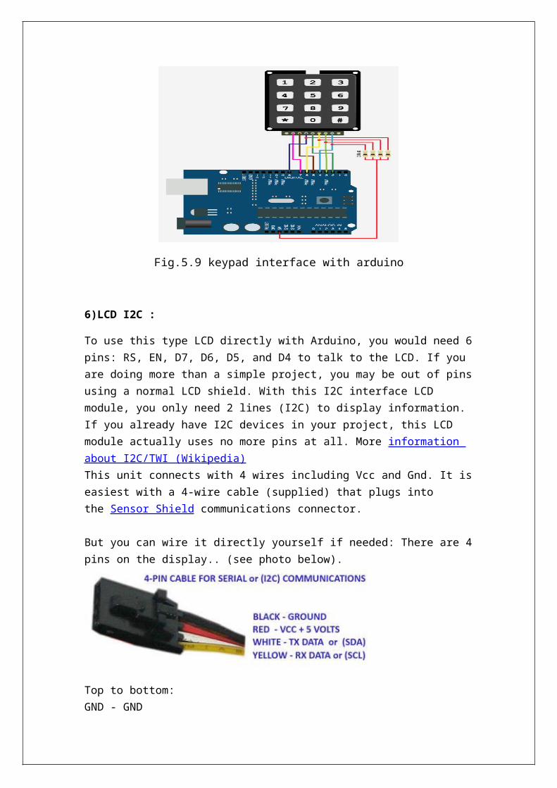
5)keypad
We have used 4 by 3 keypad. It is a simple type of keypad. It gives low output to microcontroller when key is pressed. It has 4 keys. Functions of these keys are Increment, decrement, Enter and Escape. These are used in Time setting mode .
It has been used to give access to the doctor to input or delete data .
Fig.5.9 keypad interface with arduino
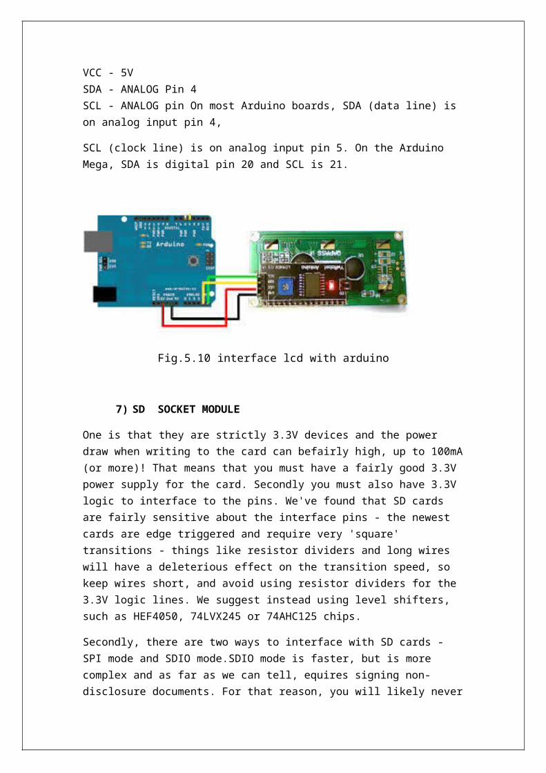
6)LCD I2C :
To use this type LCD directly with Arduino, you would need 6 pins: RS, EN, D7, D6, D5, and D4 to talk to the LCD. If you are doing more than a simple project, you may be out of pins using a normal LCD shield. With this I2C interface LCD module, you only need 2 lines (I2C) to display information. If you already have I2C devices in your project, this LCD module actually uses no more pins at all. More information about I2C/TWI (Wikipedia)This unit connects with 4 wires including Vcc and Gnd. It is easiest with a 4-wire cable (supplied) that plugs into the Sensor Shield communications connector.
But you can wire it directly yourself if needed: There are 4 pins on the display.. (see photo below).
Top to bottom:GND - GNDVCC - 5VSDA - ANALOG Pin 4SCL - ANALOG pin On most Arduino boards, SDA (data line) is on analog input pin 4,
SCL (clock line) is on analog input pin 5. On the Arduino Mega, SDA is digital pin 20 and SCL is 21.
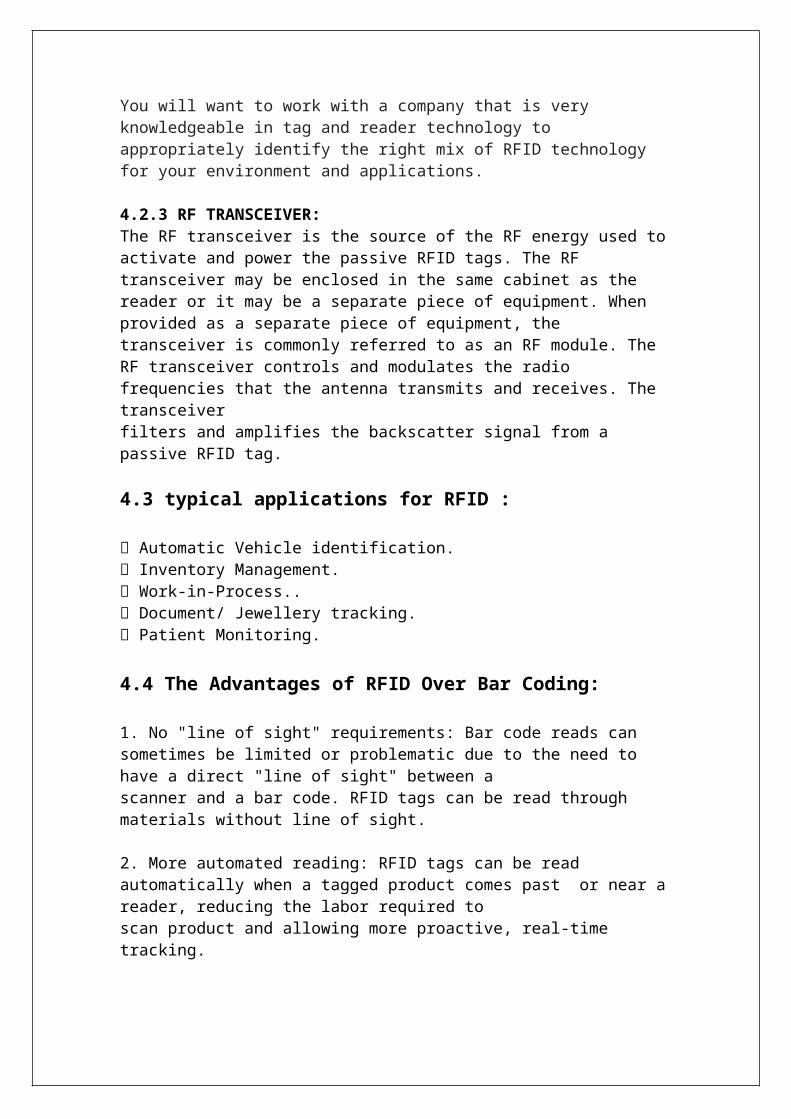
Fig.5.10 interface lcd with arduino
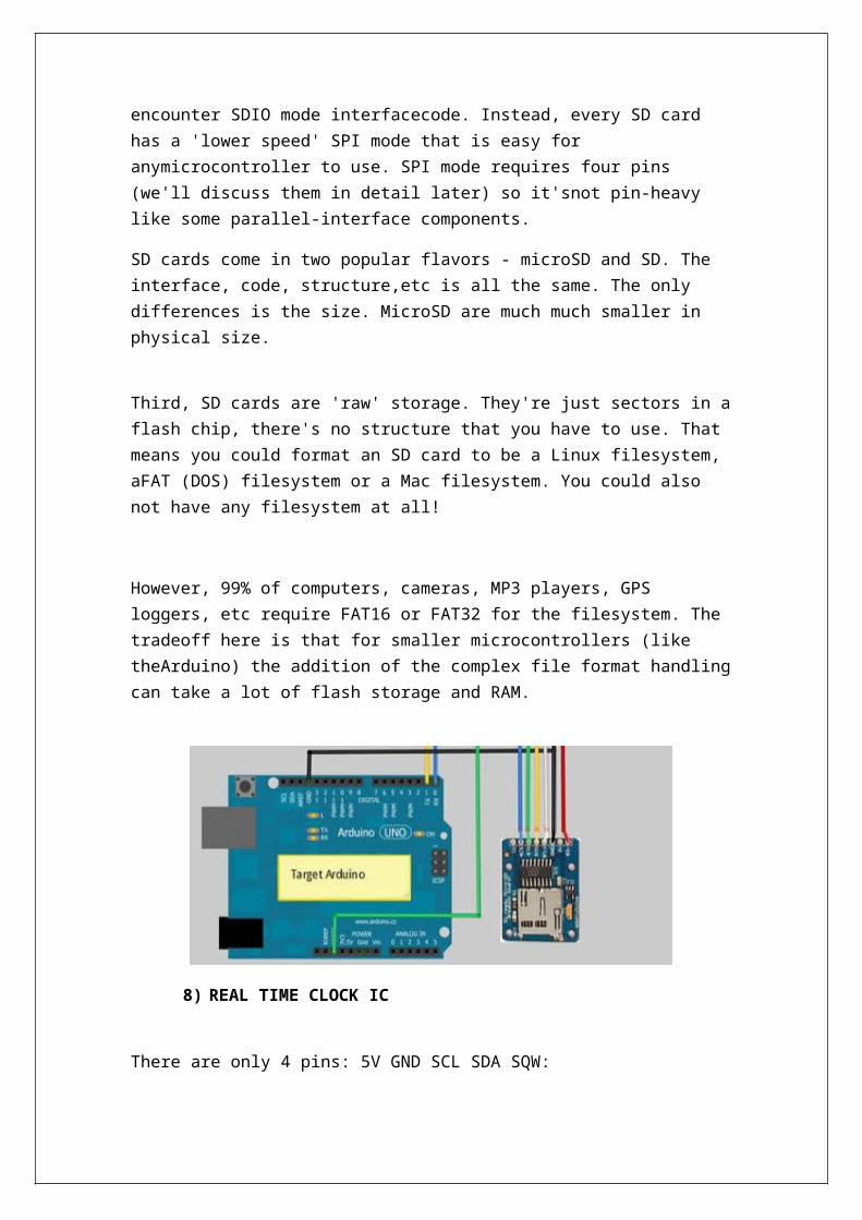
7) SD SOCKET MODULE
One is that they are strictly 3.3V devices and the power draw when writing to the card can befairly high, up to 100mA )or more(! That means that you must have a fairly good 3.3V power supply for the card. Secondly you must also have 3.3V logic to interface to the pins. We've found that SD cards are fairly sensitive about the interface pins - the newest cards are edge triggered and require very 'square' transitions - things like resistor dividers and long wires will have a deleterious effect on the transition speed, so keep wires short, and avoid using resistor dividers for the 3.3V logic lines. We suggest instead using level shifters, such as HEF4050, 74LVX245 or 74AHC125 chips.
Secondly, there are two ways to interface with SD cards - SPI mode and SDIO mode.SDIO mode is faster, but is more complex and as far as we can tell, equires signing non-disclosure documents. For that reason, you will likely never encounter SDIO mode interfacecode. Instead, every SD card has a 'lower speed' SPI mode that is easy for anymicrocontroller to use. SPI mode requires four pins )we'll discuss them in detail later( so it'snot pin-heavy like some parallel-interface components.
SD cards come in two popular flavors - microSD and SD. The interface, code, structure,etc is all the same. The only differences is the size. MicroSD are much much smaller in physical size.
Third, SD cards are 'raw' storage. They're just sectors in a flash chip, there's no structure that you have to use. That means you could format an SD card to be a Linux filesystem, aFAT )DOS( filesystem or a Mac filesystem. You could also not have any filesystem at all!
However, 99% of computers, cameras, MP3 players, GPS loggers, etc require FAT16 or FAT32 for the filesystem. The tradeoff here is that for smaller microcontrollers )like theArduino( the addition of the complex file format handling can take a lot of flash storage and RAM.
8) REAL TIME CLOCK IC
There are only 4 pins: 5V GND SCL SDA SQW:
5V is used to power to the RTC chip when you want to query it for the time. If there is no 5V signal, the chip goes to sleep using the coin cell for backup.
GND is common ground and is required SCL is the i2c clock pin - its required to talk to the RTC SDA is the i2c data pin - its required to talk to the RTC
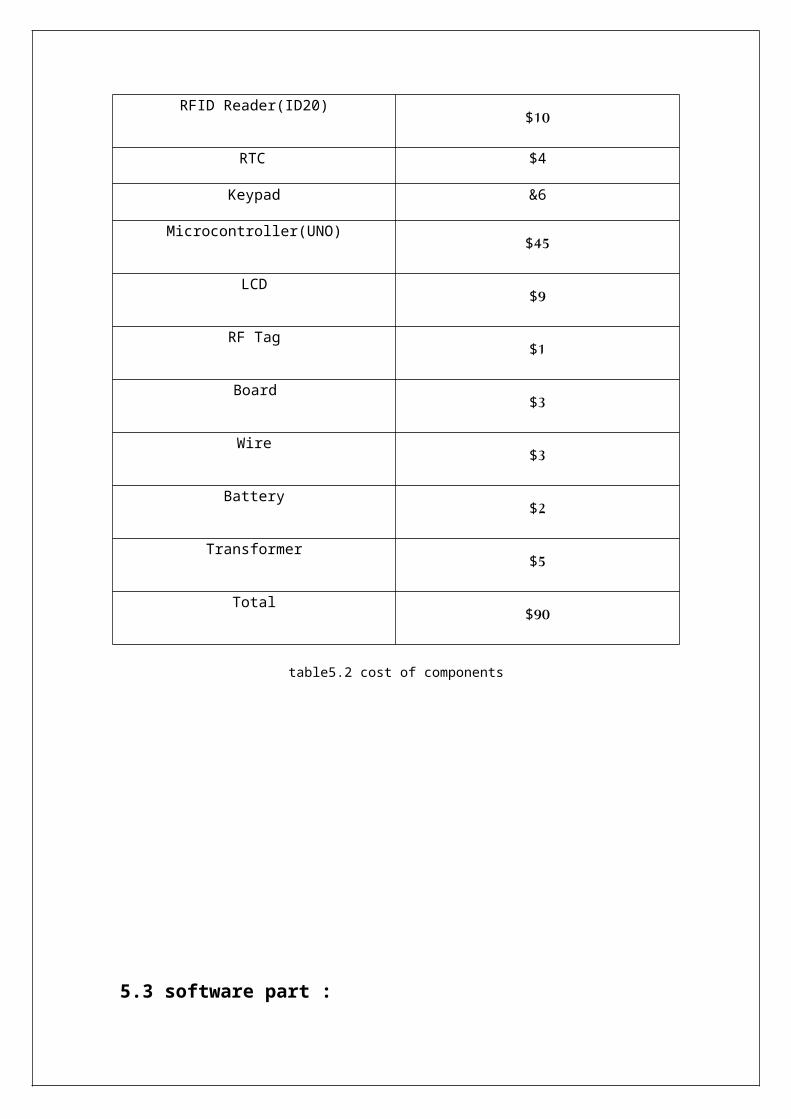
5.2 economical study:
In order for our system to be considered a practical implementation, the cost should not exceed a reasonable amount.
The following table shows the cost of the component that we used in our project:
Component of project Cost$
SD-CARD $5
RFID Reader(ID20) $10
RTC $4
Keypad &6
Microcontroller(UNO) $45
LCD $9
RF Tag $1
Board $3
Wire $3
Battery $2
Transformer $5
Total $90
table5.2 cost of components
5.3 software part :
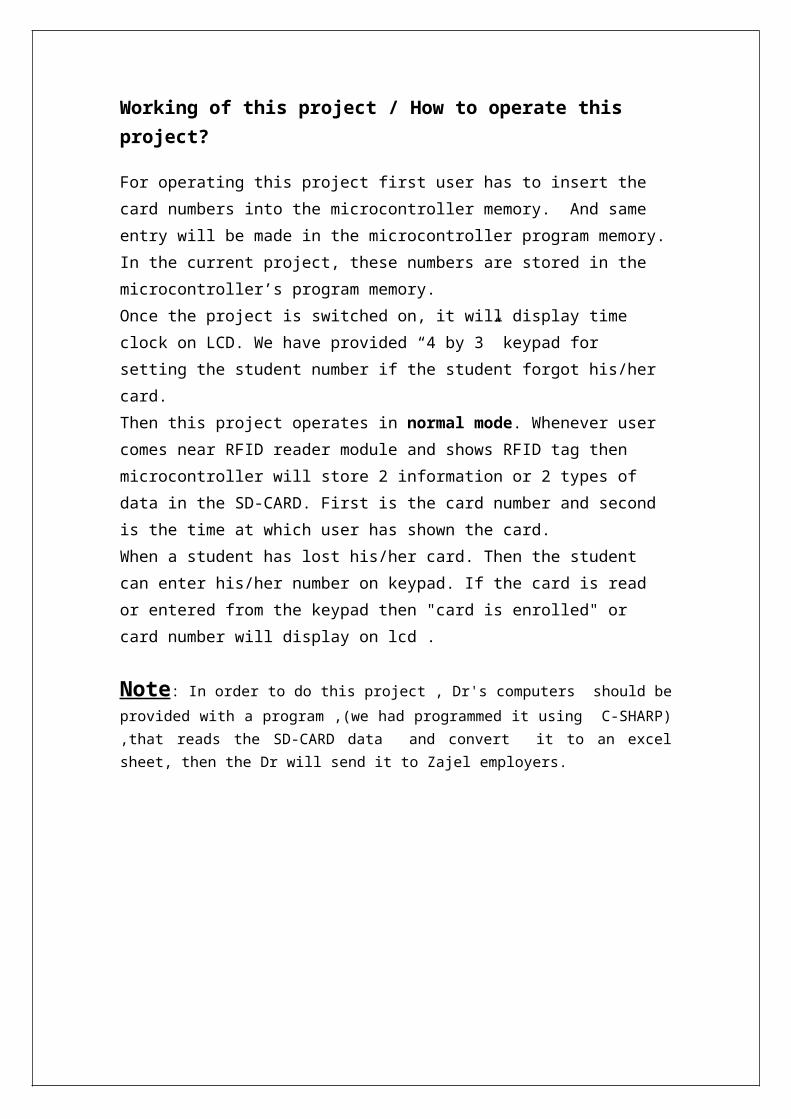
Working of this project / How to operate this project?
For operating this project first user has to insert the card numbers into the
microcontroller memory. And same entry will be made in the microcontroller
program memory. In the current project, these numbers are stored in the
microcontroller’s program memory.
Once the project is switched on, it will display time clock on LCD. We have provided
“4 by 3” keypad for setting the student number if the student forgot his/her card.
Then this project operates in normal mode. Whenever user comes near RFID reader
module and shows RFID tag then microcontroller will store 2 information or 2 types
of data in the SD-CARD. First is the card number and second is the time at which user
has shown the card.
When a student has lost his/her card. Then the student can enter his/her number on
keypad. If the card is read or entered from the keypad then "card is enrolled" or card
number will display on lcd .
Note: In order to do this project , Dr's computers should be provided with a program ,(we had programmed it using C-SHARP) ,that reads the SD-CARD data and convert it to an excel sheet, then the Dr will send it to Zajel employers.
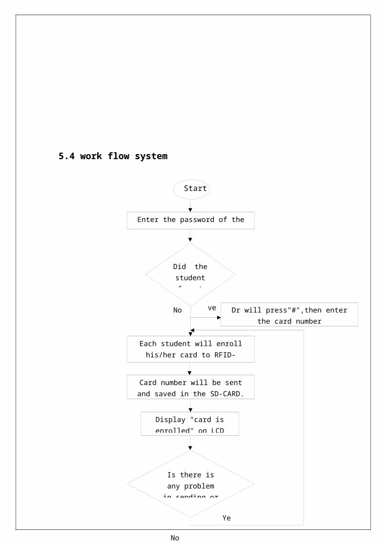
5.4 work flow system
Start
Each student will enroll his/her card to RFID-reader.
Card number will be sent and saved in the SD-CARD.
No
Display "card is enrolled" on LCD
Is there is any problem in sending or saving the card
Yes
NoEach Dr will take his/her SD-CARD connect it with PC to get the excel sheet
Send the excel sheet to Zajel
End
Enter the password of the device
yes Dr will press"#",then enter the card number
Did the student forget
CHAPTER SIX: RESULTS AND ANALYSIS:
First step: read RFID card.In this part, the serial number of the card was read , the programme was written in arduino auno language (show appendix B). so each card has a unique serial number that can be used for each student . The reader was connected to the arduino then the arduino was connected to the pc using serial usb .
Fig.6.1 the serial number of the card
This picture shows how they connect together with arduino and computer , also how they communicate.
Fig.6.2 connection of rfid reader with arduino
Second step: read from keypad.
We use keypad in order to let the student who had forgot his/her card enter his card number, and then save the number in the SD-CARD . So student will press "#" to enter the keypad function and then enter the card number.
الرقم عليها اللي الكيباد صورة Third step: real time clock.
We built the RTC circuit to save the time and date of the registration. So the time and date will be saved in the text file of SD-CARD.
سيركت رتس ال و ال و للكيباد TEXTصورة Fourth step: SD-CARD.
Because EEPROM of Arduino is too small (512kbyte) to save the text file in it, and to make it easier for each Dr to bring his/her own memory, we used the SD-CARD.The text file that will be saved in the SD-CARD will contain students number and the registration time and date.
التكست و سد ال صورة Final step: excel sheet. At the end of the week, as an example, each Dr will connect his/her
memory into his/her PC , to take the text file and convert it to excel sheet using a simple program we had made using C-SHARP and send it to ZAJEL coordinators.
+ الربنامج االكسل صورة
Chapter seven: problems:
at first, number of Arduino pins were not enough to connect all the components of our project.For example: the LCD we had used had 16 pins, which is not possible to connect, because of the other components .So we connected (IC) with it to convert it to only four pins.
SD-CARD: we had tried many types of SD-CARDS that fit the same target, because at the first of the semester the SD-CARD socket module we need was not available.صور
CHAPTER SEVEN : DISCUSSION
A careful observation of the trend of usage of RFID tags leads one to consider the
possibility of its utilization for monitoring the attendance of students in educational
institutions, with the aid of program driven computers. While every student given a
specific RFID tag attends the lecture through entrance door, a serial number (related
to each student’s matriculation number) of tag is associated with the student database
entry. So every time a student uses his/her card, the entries will be entered into the
database with the time stamp. The use of webcam might be optionally necessary to
take a snap of the person using the card. Webcam reduces proxy attendance attempts.
This is used to cross-verify in the event of an undesirable event or dispute.
Consequently, the attendance data then can be used to create many types of reports
like daily attendance details, monthly, weekly and real time feedback to parents. The
attendance score calculation can be automated using the collected data. After setting
up the student attendance RFID system from the mode of operation depicted in the
diagram shown in figure :
Fig.7.1 Illustration of the RFID system operational principle.
The tag is activated when it passes through a radio frequency (RF) field (125 kHz in
this case), which is generated by the antenna embedded within the reader box. The
program checks whether the tag is valid or not. If the tag is valid, it will continue to
the database program and registers the student’s attendance for the course. If the tag is
invalid, the program gives a notification that the tag has not been registered to any
student and requires the user to either supply a valid tag.
CHAPTER EIGHT : FUTURE WORK
The authors we have consulted in our research have shown how a system relying on
RFID- technology may be developed. This system is flexible, which means that it
may be extended by adding more modules. The cards that have been employed for
this specific system are RFID- cards, and the algorithm used has shown stable and
reliable results; moreover, this algorithm has secured important data that we have
stored on these cards. These cards can be put to use at the university and may replace
student ID cards. As demonstrated, personnel and students, alike, can use these cards
for many purposes; additional functions can always be incorporated into the
system and greater security provided to the cards. RFID- technology continues to
develop, and the time has come for us to avail ourselves of its promise and
convenience. The main aim of this research has been to demonstrate potential uses of
RFID-technology and build a system reliant on it.For the future work, this research
should be extended by adding more modules and making some updates or changes.
We are planning to add some new modules, like “Library system”, “Control of
doors”, “Payment system”, “Parking lot system”, and so on.
Simultaneously, other cards should be checked and be replaced, because cards which
were used for this research seemed to be secure less, and new cards should have
enough memory size so that we can keep more data inside of them. Furthermore, the
possibility of using some additional tools like GPS, GSM and so on is considered,
and the project for implementing such a system is started .

CHAPTER NINE : CONCLUSION AND RECOMMENDATIONS
9.1 conclusion
As the RFID technology evolves, more sophisticated applications will use the
capability of RFID to receive, store and forward data to a remote sink source. RFID
has many applications as can be imagined. In this paper, we have utilized the
versatility of RFID in implementing functional and automatic student course
attendance recording system that allows students to simply fill their attendance just by
swiping or moving their ID cards over the RFID reader which are located at the
entrance of lecture halls with a considerable degree of success and acceptability of
usage in our faculty. We hope that this system can shift the paradigm of
students’ lecture attendance monitoring in face-face classroom and provide a new,
accurate, and less cumbersome way of taking student attendance in Nigerian Higher
Institutions.
9.2 RECOMMENDATIONS
Every good engineering design innovation has limitations. This passive RFID based
lecture attendance monitoring system is not without limitation as a data collection
technology with accurate and timely data entry. Hence, the limitation of this design
would be improved upon in future by considering the following salient
Recommendations:
**By incorporating a facial recognition application that would serve to further
increase the biometric security of the system against impersonation by erring
students.
**Usage of High Frequency (HF) active RFID tags against passive Low frequency
(LF) RFID tags for better performance and flexibility of users.
**Performance evaluation of combination of thumbprint, facial recognition and
RFID technology to students’ attendance
monitoring problem.
References:
[1] http://www.vedantsystems.com/Access%20Control.html
[2]http://www.savap.org.pk/journals/ARInt./Vol.2(2)/2012(2.218).pdf
[3]http://www.dnatechindia.com/Projects/Synopsis-and-Abstract/
RFID-Based-Attendace-System.html
[4]http://pdf-collection.rhcloud.com/pdf/attendance-system-using-
rfid-module-engineersgarage/
[5]http://ebookbrowsee.net/rfid-based-metro-train-prototype-pdf-
d448219843
[6] http://www.8051projects.info/proj.asp?ID=55
[7] http://umpir.ump.edu.my/345/1/3275Firdaus.pdf
[8] http://onlinepresent.org/proceedings/vol17_2013/51.pdf
[9]http://eprints2.utem.edu.my/3406/1/
Attendance_And_Access_Control_System_Using_RFID_System_-
_24_pages.pdf
[10] www.Arduino%20Playground%20-%20DIYRFIDReader.htm
[11]http://www.grantgibson.co.uk/2012/04/how-to-get-started-with-
the-mifare-mf522-an-and-arduino/
[12]http://www.b2cqshop.com/products/203-rfid-module-kit-1356-
mhz-with-tags-spi-w-and-r-for-arduino.aspx
[13]http://www.grantgibson.co.uk/blog/wpcontent/uploads/2012/04/
ggrfid_en_ino.txt
http://www.b2cqshop.com/products/203-rfid-module-kit-1356-mhz-with-tags-spi-w-and-r-for-arduino.aspx
Attachment A:
DISCLAIMER
This report was written by students at the electrical. Engineering Department, Faculty of Engineering, An-Najah National University. It has not been altered or corrected, other than editorial corrections, as a result of assessment and it may contain language as well as content errors. The views expressed in it together with any outcomes and recommendations are solely those of the students. An-Najah National University accepts no responsibility or liability for the consequences of this report being used for a purpose other than the purpose for which it was commissioned.
Appendix B:
Code that had been used to read the serial number for the card: