Energy Upgrade CA Multifamily Energy Modeling Guidelines · PDF fileMultifamily Energy...
50
Multifamily Energy Modeling Guidelines for Energy Upgrade CA Multifamily Program Energy Upgrade CA Multifamily Energy Modeling Guidelines Version 1.1 - December 7, 2012 Prepared By: Heschong Mahone Group, Inc. 11211 Gold Country Blvd. #103 Gold River, CA 95670 Phone:(916) 962‐7001 Fax: (916) 962‐0101 e‐mail: staller@h‐m‐g.com website: www. h‐m‐g.com
Transcript of Energy Upgrade CA Multifamily Energy Modeling Guidelines · PDF fileMultifamily Energy...
Multifamily Energy Modeling Guidelines for Energy Upgrade CA Multifamily Program
Energy Upgrade CA Multifamily Energy Modeling Guidelines Version 1.1 - December 7, 2012
Prepared By:
Heschong Mahone Group, Inc. 11211 Gold Country Blvd. #103
Gold River, CA 95670 Phone:(916) 962‐7001 Fax: (916) 962‐0101
e‐mail: staller@h‐m‐g.com website: www. h‐m‐g.com
Heschong Mahone Group, Inc.
EUC‐MF Energy Modeling Guidelines ‐ Version 1.0 2 December 2012
TABLE OF CONTENTS
1. INTRODUCTION ..........................................................................................5 1.1.1 Terminology ............................................................................................... 5
1.1.2 Energy Analysis Software and Reporting Requirements ............................ 6
1.1.3 Model Calibration....................................................................................... 6
1.1.4 Fixed HERS Whole‐House Assumptions ...................................................... 6
1.1.5 HERS Whole‐House and Energy Modeling References ............................... 6
2. BUILDING INFORMATION, LIGHTING, AND APPLIANCE INPUTS .....................8 2.1 Building Element Inputs .................................................................................... 8
2.1.1 Project Design Data .................................................................................... 8
2.1.2 Project Title ................................................................................................ 9
2.1.3 Utility Rates ................................................................................................ 9
2.1.4 HERS ‐ Appliance and Lighting for Low‐Rise Multifamily ........................... 9
2.1.5 Lighting for High‐Rise Multifamily ........................................................... 12
2.1.6 Exterior Loads ........................................................................................... 12
3. THERMAL ZONING AND BUILDING ENVELOPE ............................................13 3.1 Organizing Data for Input ............................................................................... 13
3.1.1 Thermal Zoning of the Building ................................................................ 13
3.1.2 Conditioned Common Area ...................................................................... 14
3.1.3 Is it a Conditioned and Unconditioned Hallways ..................................... 15
3.1.4 Use of Multipliers for Zones ..................................................................... 15
3.1.5 Combining Exterior Surface Area ............................................................. 16
3.1.6 Multiple Buildings on One Property ......................................................... 16
3.1.7 Creating a Mirror Image of a Building ..................................................... 17
3.2 Energy Pro Zone and Room Inputs ................................................................. 17
3.2.1 Zone Element Details ............................................................................... 17
3.2.2 Room Element Details .............................................................................. 18
3.3 Exterior Surface Inputs ................................................................................... 19
3.3.1 Default Values .......................................................................................... 19
3.3.2 Attic and Cathedral Roofs ........................................................................ 19
3.3.3 Raised Floors ............................................................................................ 19
3.3.4 Slab on Grade Floors ................................................................................ 20
Heschong Mahone Group, Inc.
EUC‐MF Energy Modeling Guidelines ‐ Version 1.1 3 December 2012
3.3.5 Exterior Walls ........................................................................................... 20
3.3.6 Windows and Overhangs ......................................................................... 20
4. DOMESTIC HOT WATER (DHW) ..................................................................22 4.1.1 Equipment Efficiency Determination ........................................................ 22
4.1.2 Domestic Hot Water Inputs ...................................................................... 22
4.1.3 MF Central DHW Serving Multiple Buildings ............................................ 25
4.1.4 Renewable Energy Inputs ......................................................................... 26
5. CENTRAL PLANT .......................................................................................27 5.1 EnergyPro Inputs ............................................................................................. 27
5.1.1 Heating Hot Water Tab ............................................................................ 28
5.1.2 Chilled Water Tab ..................................................................................... 29
5.1.3 Hydronic Tab ............................................................................................ 30
6. HVAC SYSTEMS .........................................................................................31 6.1 Organizing Audit Data for Input ...................................................................... 31
6.1.1 Multipliers and Combining like Systems................................................... 31
6.1.2 Equipment Efficiency Determination ........................................................ 31
6.2 EnergyPro HVAC System Inputs ...................................................................... 32
6.2.1 General Tab and HVAC System Definition ................................................ 32
6.2.2 Distribution Tab ........................................................................................ 35
6.2.3 Residential Tab ......................................................................................... 36
6.2.4 HERS Credits Tab ...................................................................................... 36
6.2.5 Mech‐2 Tab .............................................................................................. 36
6.3 Examples of Modeling Multifamily HVAC Systems ......................................... 36
6.3.1 Forced air furnace with split DX air conditioner ....................................... 36
6.3.2 Forced Air Furnace with No Cooling ......................................................... 37
6.3.3 Split Heat Pump with Ducts in Two Locations .......................................... 37
6.3.4 Package Terminal Heat Pumps (PTHP) .................................................... 39
6.3.5 Natural Gas Wall Furnace w/Package Terminal Air Conditioner ............. 39
6.3.6 Natural Gas Wall Furnace with Split DX Cooling ...................................... 40
6.3.7 Natural Gas Wall Furnace with No Cooling ............................................. 40
6.3.8 Electric Resistance Radiant Systems ........................................................ 41
6.3.9 Low‐Rise MF Hot Water Heating Systems – Dedicated Hydronic Boiler .. 41
6.3.10 Low‐rise MF Hot Water Heating Systems – Combined Hydronic ............. 42
Heschong Mahone Group, Inc.
EUC‐MF Energy Modeling Guidelines ‐ Version 1.0 4 December 2012
6.3.11 Hydronic (Water‐loop) Heat Pumps ......................................................... 43
6.4 Ventilation Rates and Mechanical Ventilation ............................................... 45
6.4.1 Low‐Rise MF ............................................................................................. 45
6.4.2 High‐Rise MF ............................................................................................ 45
7. ENERGY ANALYSIS AND ENERGY EFFICIENCY MEASURE ELIGIBILITY ............46 7.1 Energy Analysis Using One EnergyPro File ...................................................... 46
7.2 Using Multiple Energy Models ........................................................................ 47
8. ENERGY MODEL QUALITY CONTROL .........................................................49 8.1 Energy Model Inputs ....................................................................................... 49
8.2 Reasonableness of Results .............................................................................. 50
EUC‐M
INT
This dservin
This dand tto uswhichunits are sosomeeffici
This dreadesoftwavaila
1.1.1
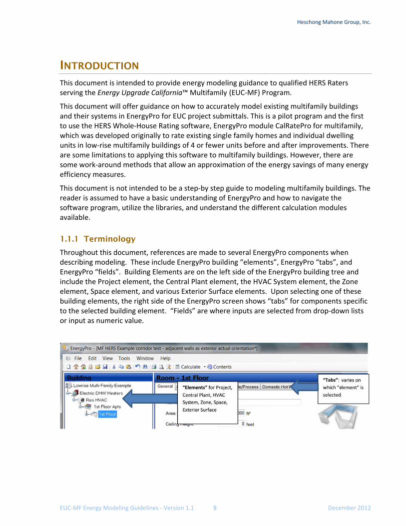
ThroudescrEnergincludelembuildto theor inp
MF Energy Mod
TRODUC
document isng the Energ
document wtheir systeme the HERS Wh was develoin low‐rise mome limitatie work‐arounency measu
document iser is assumeware programable.
1 Termino
ughout this dribing modegyPro “fieldsde the Projeent, Space eing elemente selected bput as nume
deling Guidelin
TION s intended togy Upgrade C
will offer guids in EnergyPWhole‐Housoped originamultifamily ons to applynd methods res.
s not intended to have a m, utilize the
ology
document, rling. These s”. Building ect element, element, andts, the right suilding elemeric value.
nes ‐ Version 1.
o provide enCalifornia™
dance on hoPro for EUC pse Rating sofally to rate ebuildings of ying this softthat allow a
ed to be a stbasic underse libraries, a
references ainclude EnerElements arthe Central d various Extside of the Ement. “Fields
.1 5
nergy modeliMultifamily
w to accuratproject submftware, Enerxisting singl4 or fewer utware to muan approxim
ep‐by step gstanding of nd understa
re made to rgyPro buildre on the leftPlant elemeterior SurfacEnergyPro scs” are where
ing guidance(EUC‐MF) P
tely model emittals. This irgyPro modue family homunits before ultifamily bumation of the
guide to modEnergyPro aand the diffe
several Enering “element side of theent, the HVAce elements.creen shows e inputs are
He
e to qualifiedrogram.
existing multis a pilot proule CalRatePmes and indiand after imildings. Howe energy savi
deling multiand how to nerent calcula
rgyPro compnts”, EnergyPe EnergyPro AC System el. Upon selec“tabs” for cselected fro
schong Mahone
Dece
d HERS Rate
tifamily buildogram and thPro for multifividual dwelmprovementwever, there ings of many
family buildnavigate the tion module
ponents whePro “tabs”, abuilding treelement, the cting one of components om drop‐dow
e Group, Inc.
mber 2012
ers
dings he first family, ling ts. There are y energy
ings. The
es
en and e and Zone these specific wn lists
Heschong Mahone Group, Inc.
EUC‐MF Energy Modeling Guidelines ‐ Version 1.0 6 December 2012
1.1.2 Energy Analysis Software and Reporting Requirements
Either the Res Performance or CalRatePro module of EnergyPro shall be used for low‐rise multifamily building models. Both of these modules allow for parametric alternatives in energy efficiency measure analysis using a single .bld file. The Non‐Residential Performance module shall be used for high‐rise multifamily building models. For the purposes of this document, the term “EnergyPro” will be used whenever the information applies across these three different modules of EnergyPro. “CalRatePro,” “Res Performance,” and “Non‐Residential Performance” will be used when the guidelines apply specifically to those modules.
High‐rise residential for Title 24 Part 6 and EUC program related energy analysis, is any multifamily building with four or more habitable floors. A four story building with retail on the ground level and three levels of multifamily is considered a high‐rise multifamily building.
Program incentives are based on site energy savings, and project teams are required to report site savings from the ECON‐2 report, which can be generated using CalRatePro, Res Performance, or Non‐Res Performance modules of EnergyPro.
The ECON‐2 report includes annual site energy by end‐use and total annual TDV savings percent improvement by energy efficiency measure, for the reference (baseline, or existing) case and the proposed case. The EUC‐MF program utilizes the site energy improvements on the ECON‐2 report to qualify for program participation and to determine the project incentive tier.
1.1.3 Model Calibration
Calibrating the models to utility usage data is not a program requirement. While it is good practice to collect utility bills and input them into EnergyPro to compare against the modeled energy use for accuracy, this is currently not required for program participation.
1.1.4 Fixed HERS Whole-House Assumptions
Many HERS Whole‐house requirements are based on the Title 24 Part 6 Residential ACM and cannot be changed by the software vendor without approval by the Energy Commission. Understanding the fixed assumption for low‐rise multifamily HERS Whole‐house modeling with CalRatePro, and how they impact the results is important. These assumptions are described in in the appropriate sections of this document.
1.1.5 HERS Whole-House and Energy Modeling References
The following documents prepared by the Energy Commission will assist energy analysts and HERS Raters in understanding the energy modeling software and requirements as they pertain to the HERS Whole‐House and EnergyPro software capabilities. Several are accessible from the EnergyPro help menu.
HERS Technical Manual explains the requirements for the California Home Energy Rating System (HERS) Program, including requirements for HERS providers, modeling procedures and assumptions, analysis procedures, reporting, and other requirements of the CA HERS program. The document can be downloaded at the following website:

Heschong Mahone Group, Inc.
EUC‐MF Energy Modeling Guidelines ‐ Version 1.1 7 December 2012
http://www.energy.ca.gov/2008publications/CEC‐400‐2008‐012/CEC‐400‐2008‐012‐CMF.PDF
2008 Building Energy Efficiency Standards for Residential and Nonresidential Buildings is the current version of the state building energy code which the HERS Technical Manual is structured around. The document can be downloaded at the following website: http://www.energy.ca.gov/2008publications/CEC‐400‐2008‐001/CEC‐400‐2008‐001‐CMF.PDF
Residential and Nonresidential Manuals are intended to help energy consultants comply with and enforce the California Title 24 Part 6 standards, and are useful for understanding requirements for alterations and additions. The documents can be downloaded at the following websites: http://www.energy.ca.gov/title24/2008standards/residential_manual.html and http://www.energy.ca.gov/title24/2008standards/nonresidential_manual.html
Residential and Nonresidential Alternative Calculation Manuals (ACM) include approved calculation methods for Title 24 Part 6 compliance, and therefore offer insight into the calculation methodology within the EnergyPro (compliance) software. The documents can be downloaded at the following websites: http://www.energy.ca.gov/2008publications/CEC‐400‐2008‐002/CEC‐400‐2008‐002‐CMF.PDF and http://www.energy.ca.gov/2008publications/CEC‐400‐2008‐003/CEC‐400‐2008‐003‐CMF.PDF
2008 Joint Appendices provide references for weather data, construction assembly descriptions, residential and non‐residential HERS verification procedures, and other calculation approaches used by the HERS Whole‐House software. The document can be downloaded at the following website: http://www.energy.ca.gov/2008publications/CEC‐400‐2008‐004/CEC‐400‐2008‐004‐CMF.PDF
This document has been prepared by the Heschong Mahone Group (HMG) and shall not be distributed or used by other multifamily retrofit programs without HMG’s written consent.
Heschong Mahone Group, Inc.
EUC‐MF Energy Modeling Guidelines ‐ Version 1.0 8 December 2012
2. BUILDING INFORMATION, LIGHTING, AND APPLIANCE INPUTS This section provides guidance on the building element of EnergyPro. The Building element includes basic project design data. For low‐rise multifamily projects using the CalRatePro and Res Performance modules, the Building element also includes the lighting and appliances input on the HERS tab when. The HERS tab is not used for high‐rise projects. Modeling lighting and appliances for high‐rise is different than low‐rise and is discussed below.
2.1 Building Element Inputs
Data for these inputs is taken from data collection forms:
1) Multifamily Project Information Form – page 1/1 2) Multifamily Building Information Data Collection Form – page 1/3: the first half has
the project design data 3A) Multifamily Dwelling Unit – Equipment Form – page 2/2 3B) Multifamily Dwelling Unit – Lighting Form page 1/1
Inputs on the Designer, Lighting Designer, Mechanical Designer, and Outdoor tabs are not necessary for EUC‐MF project submittals.
2.1.1 Project Design Data
Input information regarding the project design data.
Front Orientation
This is the direction the front door is orientated towards. There may be front doors in multifamily buildings oriented in different directions. In all cases it is essential that the sketches clearly show the north arrow as it is modeled.
Rotation
The purpose of rotation is to simply rotate the entire building from the front orientation selected above. It is essentially rotates the building and exterior surface orientations in addition to the selected front orientation. So, input front as West (270°) and inputting rotation of 10° would result in front being oriented 280°. This rotation must be done after the entire building has been modeled in order to work properly. This is useful when you have identical buildings with different orientations. It will allow you to model one building, perform a “save as”, and rotate to the other building’s orientation.
Number of Dwelling Units
The total number of dwelling units for the building must be modeled correctly as this value is used for the domestic hot water, lighting, and appliance calculations.

Heschong Mahone Group, Inc.
EUC‐MF Energy Modeling Guidelines ‐ Version 1.1 9 December 2012
Location- Climate Zones
The correct climate zone must be selected to ensure an accurate analysis. Default values found for the location of the building must be used and not altered.
2.1.2 Project Title
Input the building number, or other designation, in the name field. The ECON‐2 report uses the project name from this field. Be sure to input the building designation completely so the ECON‐2 reflects the actual building you are modeling, distinct from other buildings you may be modeling for that property.
2.1.3 Utility Rates
Select the electricity and natural gas rates for the project. When choosing a utility rate click on the hour glass icon and select a rate that is in the software. Do not change anything in these rates. The rates are frequently updated in the software.
2.1.4 HERS - Appliance and Lighting for Low-Rise Multifamily
Low‐Rise ‐ The inputs on the HERS tab are multiplied by the number of dwelling units for low‐rise multifamily projects and are ignored in high‐rise building models. Averaging sampled dwelling unit lighting and appliances for HERS tab inputs is required for all low‐rise projects.
High‐rise ‐ High‐rise multifamily projects, using the Non‐Res Performance module, are not connected to the HERS tab. Do not input high‐rise dwelling unit appliances and lighting on the HERS tab.
Appliances
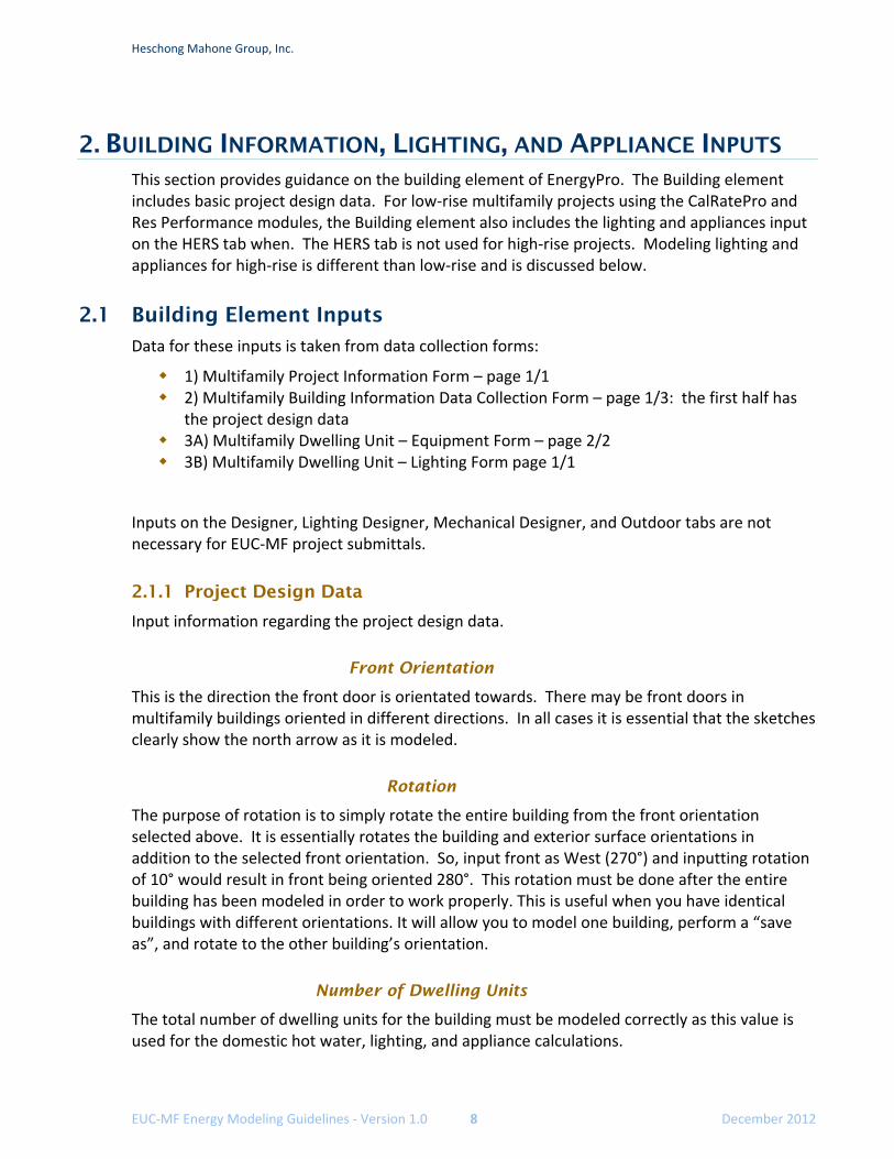
Refrigerators ‐ There will likely be multiple refrigerator types that have different UEC values (kWh/yr). It is necessary to calculate the average UEC for input into the HERS tab.
The table below presents an example method to track and calculate the average UEC for the surveyed refrigerators that needs to be input in the HERS Whole‐house software. The average UEC for the refrigerators in this example is 594 kWh per year and is input into the HERS Whole‐house software on the HERS tab. This is only one example and this type of calculation may need to be performed on: dishwashers, lighting, HVAC efficiencies, DHW efficiencies, etc.
Heschong Mahone Group, Inc.
EUC‐MF Energy Modeling Guidelines ‐ Version 1.0 10 December 2012
Figure 1: Example Average Refrigerator Calculation
Washer and dryer should be input as “none” unless they are located in each dwelling unit. Only the electricity is accounted for when clothes washers are selected on the HERS tab. The hot water consumed by clothes washers is not accounted for in the analysis.
Dishwashers ‐ All low‐rise residential projects that are modeled with the CalRatePro and Residential Performance modules have a dishwasher per each dwelling unit. The electrical energy use is reported in appliance end‐use. Hot water usage for dishwashers is not accounted for in the HERS Whole‐house analysis. If dishwashers do not exist in the building use the default dishwasher energy factor of 0.46. Addition of a dishwasher must also be accounted for in the post‐retrofit model.
Pools and spas should not be included in the model.
Interior Dwelling Unit Lighting – HERS Tab
For low‐rise multifamily buildings, it is not necessary to collect the lighting wattage for the dwelling unit lighting. The type, quantity, control, and location of lighting are the required EnergyPro inputs. The software currently accepts whole numbers only for the HERS tab lighting fixture inputs. This may result in the slightly inaccurate dwelling unit lighting for multifamily projects when the average number of fixtures is a fraction.
Type Audited Manufacturer Model # UEC Notes
1 bed yes Hotpoint CTH14CYTCRWH 775 default used, can't locate
1 bed yes Hotpoint CTH14CYTCRWH 775 default used, can't locate
house yes GE GTS18CBSARWW 480
house yes Whirlpool ET8WTEXVQ01 388
house yes GE GTS18FBSARWW 482
house yes Hotpoint HTS15BBMBRWW 775 default used, can't locate
T yes Magic Chef CTB1821ARW 480
U yes Whirlpool EHT141DTWR1 775 default used, can't locate
V yes Magic Chef RB191TV 775 default used, can't locate
W yes Hotpoint CTX18CAXGRWH 775 default used, can't locate
W yes GE GTH18DBXARWW 387
X yes Hotpoint CTH18EASMRWH 514
X yes GE GTH18DBXARWW 387
X yes GE GTH18DBXARWW 387
X yes Magic Chef RB191TV 775 default used, can't locate
Y yes GE GTH18DBXARWW 387 used for all replacements
Y yes Hotpoint CTH14CYTCRWH 775 default used, can't locate
Average UEC 594
Refrigerators
Heschong Mahone Group, Inc.
EUC‐MF Energy Modeling Guidelines ‐ Version 1.1 11 December 2012
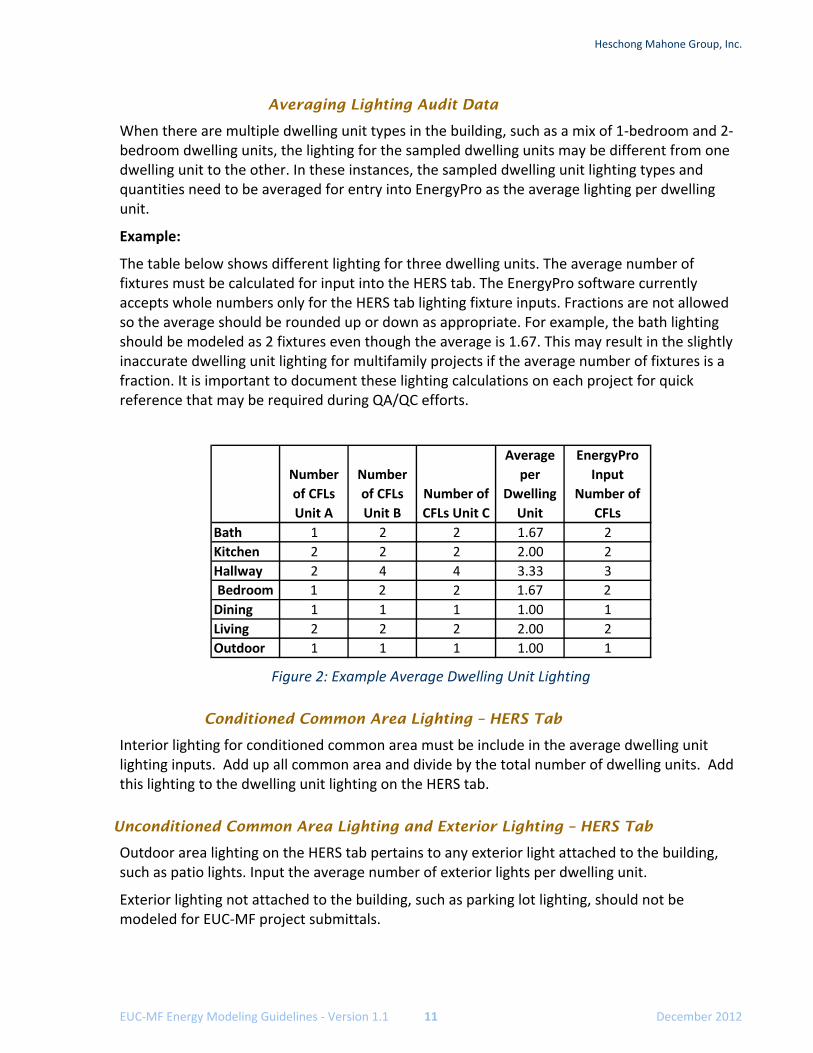
Averaging Lighting Audit Data
When there are multiple dwelling unit types in the building, such as a mix of 1‐bedroom and 2‐bedroom dwelling units, the lighting for the sampled dwelling units may be different from one dwelling unit to the other. In these instances, the sampled dwelling unit lighting types and quantities need to be averaged for entry into EnergyPro as the average lighting per dwelling unit.
Example:
The table below shows different lighting for three dwelling units. The average number of fixtures must be calculated for input into the HERS tab. The EnergyPro software currently accepts whole numbers only for the HERS tab lighting fixture inputs. Fractions are not allowed so the average should be rounded up or down as appropriate. For example, the bath lighting should be modeled as 2 fixtures even though the average is 1.67. This may result in the slightly inaccurate dwelling unit lighting for multifamily projects if the average number of fixtures is a fraction. It is important to document these lighting calculations on each project for quick reference that may be required during QA/QC efforts.
Figure 2: Example Average Dwelling Unit Lighting
Conditioned Common Area Lighting – HERS Tab
Interior lighting for conditioned common area must be include in the average dwelling unit lighting inputs. Add up all common area and divide by the total number of dwelling units. Add this lighting to the dwelling unit lighting on the HERS tab.
Unconditioned Common Area Lighting and Exterior Lighting – HERS Tab
Outdoor area lighting on the HERS tab pertains to any exterior light attached to the building, such as patio lights. Input the average number of exterior lights per dwelling unit.
Exterior lighting not attached to the building, such as parking lot lighting, should not be modeled for EUC‐MF project submittals.
Number
of CFLs
Unit A
Number
of CFLs
Unit B
Number of
CFLs Unit C
Average
per
Dwelling
Unit
EnergyPro
Input
Number of
CFLs
Bath 1 2 2 1.67 2
Kitchen 2 2 2 2.00 2
Hallway 2 4 4 3.33 3
Bedroom 1 2 2 1.67 2
Dining 1 1 1 1.00 1
Living 2 2 2 2.00 2
Outdoor 1 1 1 1.00 1
Heschong Mahone Group, Inc.
EUC‐MF Energy Modeling Guidelines ‐ Version 1.0 12 December 2012
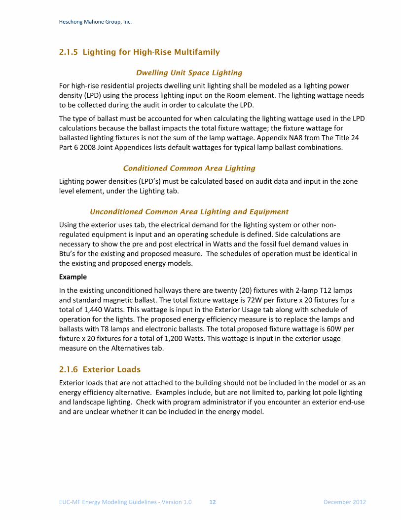
2.1.5 Lighting for High-Rise Multifamily
Dwelling Unit Space Lighting
For high‐rise residential projects dwelling unit lighting shall be modeled as a lighting power density (LPD) using the process lighting input on the Room element. The lighting wattage needs to be collected during the audit in order to calculate the LPD.
The type of ballast must be accounted for when calculating the lighting wattage used in the LPD calculations because the ballast impacts the total fixture wattage; the fixture wattage for ballasted lighting fixtures is not the sum of the lamp wattage. Appendix NA8 from The Title 24 Part 6 2008 Joint Appendices lists default wattages for typical lamp ballast combinations.
Conditioned Common Area Lighting
Lighting power densities (LPD’s) must be calculated based on audit data and input in the zone level element, under the Lighting tab.
Unconditioned Common Area Lighting and Equipment
Using the exterior uses tab, the electrical demand for the lighting system or other non‐regulated equipment is input and an operating schedule is defined. Side calculations are necessary to show the pre and post electrical in Watts and the fossil fuel demand values in Btu’s for the existing and proposed measure. The schedules of operation must be identical in the existing and proposed energy models.
Example
In the existing unconditioned hallways there are twenty (20) fixtures with 2‐lamp T12 lamps and standard magnetic ballast. The total fixture wattage is 72W per fixture x 20 fixtures for a total of 1,440 Watts. This wattage is input in the Exterior Usage tab along with schedule of operation for the lights. The proposed energy efficiency measure is to replace the lamps and ballasts with T8 lamps and electronic ballasts. The total proposed fixture wattage is 60W per fixture x 20 fixtures for a total of 1,200 Watts. This wattage is input in the exterior usage measure on the Alternatives tab.
2.1.6 Exterior Loads
Exterior loads that are not attached to the building should not be included in the model or as an energy efficiency alternative. Examples include, but are not limited to, parking lot pole lighting and landscape lighting. Check with program administrator if you encounter an exterior end‐use and are unclear whether it can be included in the energy model.
Heschong Mahone Group, Inc.
EUC‐MF Energy Modeling Guidelines ‐ Version 1.1 13 December 2012
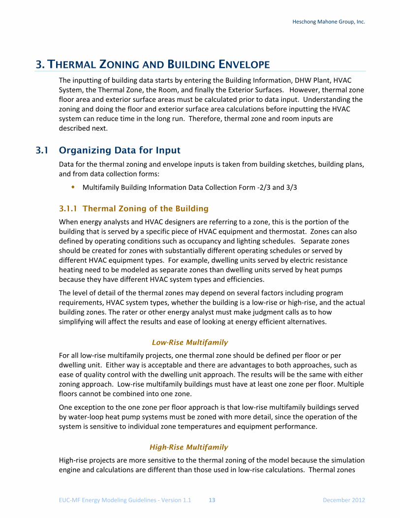
3. THERMAL ZONING AND BUILDING ENVELOPE The inputting of building data starts by entering the Building Information, DHW Plant, HVAC System, the Thermal Zone, the Room, and finally the Exterior Surfaces. However, thermal zone floor area and exterior surface areas must be calculated prior to data input. Understanding the zoning and doing the floor and exterior surface area calculations before inputting the HVAC system can reduce time in the long run. Therefore, thermal zone and room inputs are described next.
3.1 Organizing Data for Input
Data for the thermal zoning and envelope inputs is taken from building sketches, building plans, and from data collection forms:
Multifamily Building Information Data Collection Form ‐2/3 and 3/3
3.1.1 Thermal Zoning of the Building
When energy analysts and HVAC designers are referring to a zone, this is the portion of the building that is served by a specific piece of HVAC equipment and thermostat. Zones can also defined by operating conditions such as occupancy and lighting schedules. Separate zones should be created for zones with substantially different operating schedules or served by different HVAC equipment types. For example, dwelling units served by electric resistance heating need to be modeled as separate zones than dwelling units served by heat pumps because they have different HVAC system types and efficiencies.
The level of detail of the thermal zones may depend on several factors including program requirements, HVAC system types, whether the building is a low‐rise or high‐rise, and the actual building zones. The rater or other energy analyst must make judgment calls as to how simplifying will affect the results and ease of looking at energy efficient alternatives.
Low-Rise Multifamily
For all low‐rise multifamily projects, one thermal zone should be defined per floor or per dwelling unit. Either way is acceptable and there are advantages to both approaches, such as ease of quality control with the dwelling unit approach. The results will be the same with either zoning approach. Low‐rise multifamily buildings must have at least one zone per floor. Multiple floors cannot be combined into one zone.
One exception to the one zone per floor approach is that low‐rise multifamily buildings served by water‐loop heat pump systems must be zoned with more detail, since the operation of the system is sensitive to individual zone temperatures and equipment performance.
High-Rise Multifamily
High‐rise projects are more sensitive to the thermal zoning of the model because the simulation engine and calculations are different than those used in low‐rise calculations. Thermal zones
Heschong Mahone Group, Inc.
EUC‐MF Energy Modeling Guidelines ‐ Version 1.0 14 December 2012
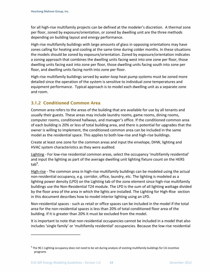
for all high‐rise multifamily projects can be defined at the modeler’s discretion. A thermal zone per floor, zoned by exposure/orientation, or zoned by dwelling unit are the three methods depending on building layout and energy performance.
High‐rise multifamily buildings with large amounts of glass in opposing orientations may have zones calling for heating and cooling at the same time during colder months. In these situations the models should be zoned by exposure/orientation. Zoned by exposure/orientation indicates a zoning approach that combines the dwelling units facing west into one zone per floor, those dwelling units facing east into zone per floor, those dwelling units facing south into zone per floor, and dwelling units facing north into zone per floor.
High‐rise multifamily buildings served by water‐loop heat pump systems must be zoned more detailed since the operation of the system is sensitive to individual zone temperatures and equipment performance. Typical approach is to model each dwelling unit as a separate zone and room.
3.1.2 Conditioned Common Area
Common area refers to the areas of the building that are available for use by all tenants and usually their guests. These areas may include laundry rooms, game rooms, dining rooms, computer rooms, conditioned hallways, and manager’s office. If the conditioned common area of each building is 20% or less of total building area, and there is potential for upgrades that the owner is willing to implement, the conditioned common area can be included in the same model as the residential space. This applies to both low‐rise and high‐rise buildings.
Create at least one zone for the common areas and input the envelope, DHW, lighting and HVAC system characteristics as they were audited.
Lighting ‐ For low‐rise residential common areas, select the occupancy ‘multifamily residential’ and input the lighting as part of the average dwelling unit lighting fixture count on the HERS tab1.
High‐rise ‐ The common area in high‐rise multifamily buildings can be modeled using the actual non‐residential occupancy, e.g. corridor, office, laundry, etc. The lighting is modeled as a lighting power density (LPD) on the Lighting tab of the zone element since high‐rise multifamily buildings use the Non‐Residential T24 module. The LPD is the sum of all lighting wattage divided by the floor area of the area in which the lights are installed. The Lighting for High‐Rise section in this document describes how to model interior lighting using an LPD.
Non‐residential spaces ‐ such as retail or office spaces can be included in the model if the total area for the non‐residential spaces is less than 20% of total conditioned floor area of the building. If it is greater than 20% it must be excluded from the model.
It is important to note that non‐residential occupancies cannot be included in a model that also includes ‘single family’ or ‘multifamily residential’ occupancies. Because the low‐rise residential
1 The 90.1 Lighting occupancy does not need to be set during analysis of existing multifamily buildings for CA incentive
programs
Heschong Mahone Group, Inc.
EUC‐MF Energy Modeling Guidelines ‐ Version 1.1 15 December 2012
and non‐residential occupancies use different simulation engines, EnergyPro will crash if a .bld file includes both.
3.1.3 Is it a Conditioned and Unconditioned Hallways
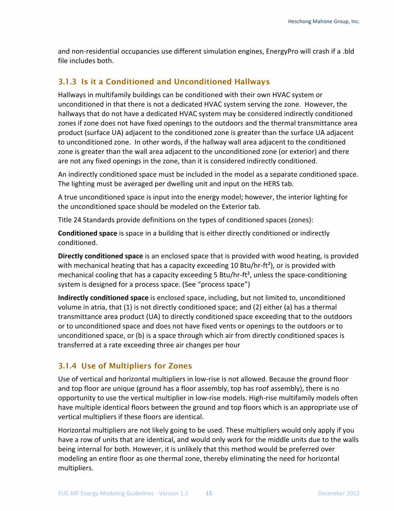
Hallways in multifamily buildings can be conditioned with their own HVAC system or unconditioned in that there is not a dedicated HVAC system serving the zone. However, the hallways that do not have a dedicated HVAC system may be considered indirectly conditioned zones if zone does not have fixed openings to the outdoors and the thermal transmittance area product (surface UA) adjacent to the conditioned zone is greater than the surface UA adjacent to unconditioned zone. In other words, if the hallway wall area adjacent to the conditioned zone is greater than the wall area adjacent to the unconditioned zone (or exterior) and there are not any fixed openings in the zone, than it is considered indirectly conditioned.
An indirectly conditioned space must be included in the model as a separate conditioned space. The lighting must be averaged per dwelling unit and input on the HERS tab.
A true unconditioned space is input into the energy model; however, the interior lighting for the unconditioned space should be modeled on the Exterior tab.
Title 24 Standards provide definitions on the types of conditioned spaces (zones):
Conditioned space is space in a building that is either directly conditioned or indirectly conditioned.
Directly conditioned space is an enclosed space that is provided with wood heating, is provided with mechanical heating that has a capacity exceeding 10 Btu/hr‐ft²), or is provided with mechanical cooling that has a capacity exceeding 5 Btu/hr‐ft², unless the space‐conditioning system is designed for a process space. (See “process space”)
Indirectly conditioned space is enclosed space, including, but not limited to, unconditioned volume in atria, that (1) is not directly conditioned space; and (2) either (a) has a thermal transmittance area product (UA) to directly conditioned space exceeding that to the outdoors or to unconditioned space and does not have fixed vents or openings to the outdoors or to unconditioned space, or (b) is a space through which air from directly conditioned spaces is transferred at a rate exceeding three air changes per hour
3.1.4 Use of Multipliers for Zones
Use of vertical and horizontal multipliers in low‐rise is not allowed. Because the ground floor and top floor are unique (ground has a floor assembly, top has roof assembly), there is no opportunity to use the vertical multiplier in low‐rise models. High‐rise multifamily models often have multiple identical floors between the ground and top floors which is an appropriate use of vertical multipliers if these floors are identical.
Horizontal multipliers are not likely going to be used. These multipliers would only apply if you have a row of units that are identical, and would only work for the middle units due to the walls being internal for both. However, it is unlikely that this method would be preferred over modeling an entire floor as one thermal zone, thereby eliminating the need for horizontal multipliers.
Heschong Mahone Group, Inc.
EUC‐MF Energy Modeling Guidelines ‐ Version 1.0 16 December 2012
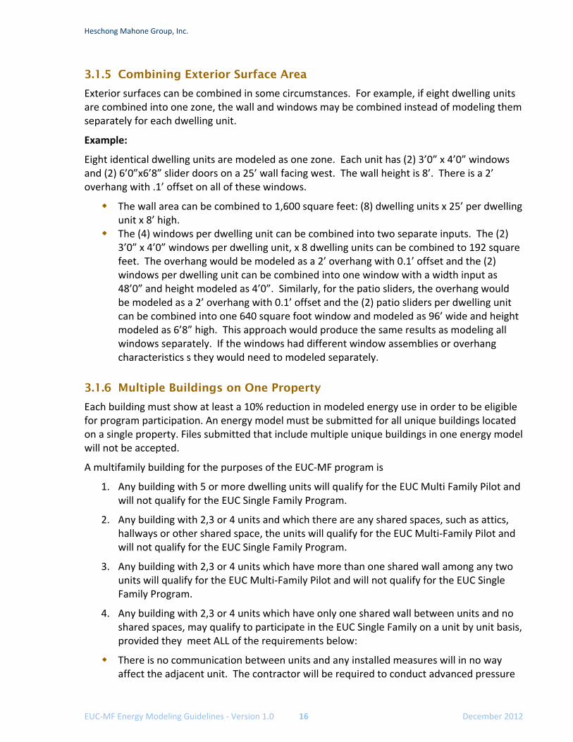
3.1.5 Combining Exterior Surface Area
Exterior surfaces can be combined in some circumstances. For example, if eight dwelling units are combined into one zone, the wall and windows may be combined instead of modeling them separately for each dwelling unit.
Example:
Eight identical dwelling units are modeled as one zone. Each unit has (2) 3’0” x 4’0” windows and (2) 6’0”x6’8” slider doors on a 25’ wall facing west. The wall height is 8’. There is a 2’ overhang with .1’ offset on all of these windows.
The wall area can be combined to 1,600 square feet: (8) dwelling units x 25’ per dwelling unit x 8’ high.
The (4) windows per dwelling unit can be combined into two separate inputs. The (2) 3’0” x 4’0” windows per dwelling unit, x 8 dwelling units can be combined to 192 square feet. The overhang would be modeled as a 2’ overhang with 0.1’ offset and the (2) windows per dwelling unit can be combined into one window with a width input as 48’0” and height modeled as 4’0”. Similarly, for the patio sliders, the overhang would be modeled as a 2’ overhang with 0.1’ offset and the (2) patio sliders per dwelling unit can be combined into one 640 square foot window and modeled as 96’ wide and height modeled as 6’8” high. This approach would produce the same results as modeling all windows separately. If the windows had different window assemblies or overhang characteristics s they would need to modeled separately.
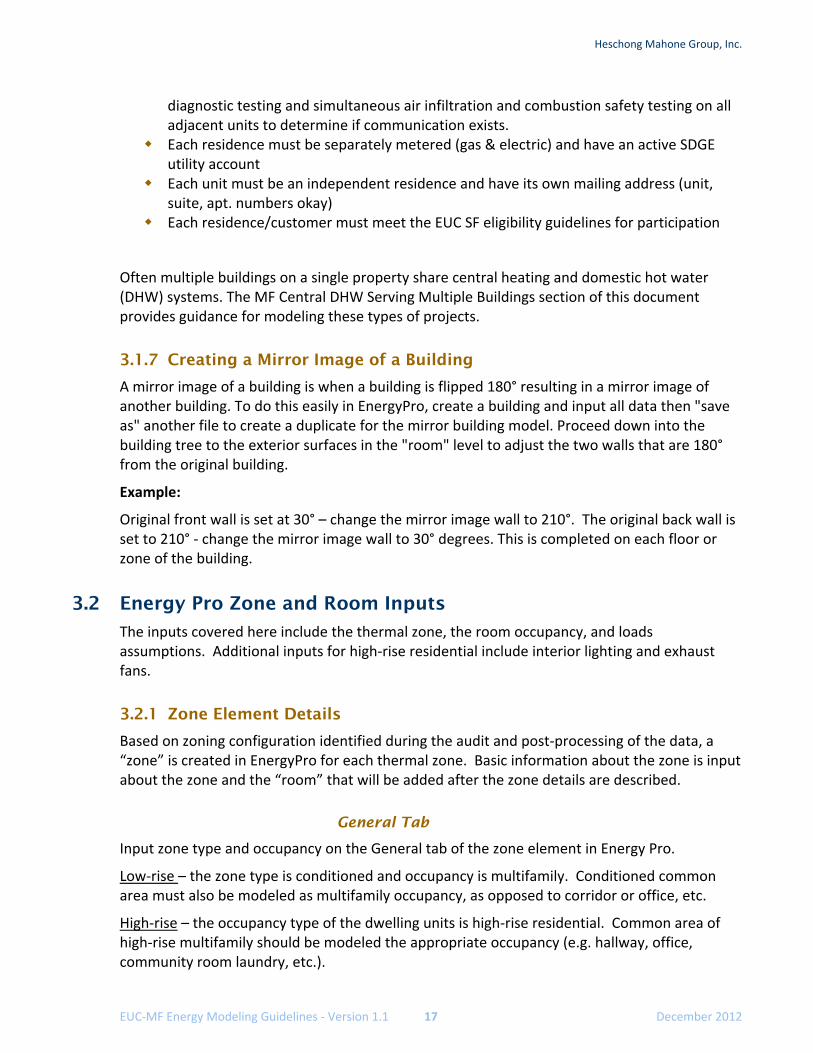
3.1.6 Multiple Buildings on One Property
Each building must show at least a 10% reduction in modeled energy use in order to be eligible for program participation. An energy model must be submitted for all unique buildings located on a single property. Files submitted that include multiple unique buildings in one energy model will not be accepted.
A multifamily building for the purposes of the EUC‐MF program is
1. Any building with 5 or more dwelling units will qualify for the EUC Multi Family Pilot and will not qualify for the EUC Single Family Program.
2. Any building with 2,3 or 4 units and which there are any shared spaces, such as attics, hallways or other shared space, the units will qualify for the EUC Multi‐Family Pilot and will not qualify for the EUC Single Family Program.
3. Any building with 2,3 or 4 units which have more than one shared wall among any two units will qualify for the EUC Multi‐Family Pilot and will not qualify for the EUC Single Family Program.
4. Any building with 2,3 or 4 units which have only one shared wall between units and no shared spaces, may qualify to participate in the EUC Single Family on a unit by unit basis, provided they meet ALL of the requirements below:
There is no communication between units and any installed measures will in no way affect the adjacent unit. The contractor will be required to conduct advanced pressure
Heschong Mahone Group, Inc.
EUC‐MF Energy Modeling Guidelines ‐ Version 1.1 17 December 2012
diagnostic testing and simultaneous air infiltration and combustion safety testing on all adjacent units to determine if communication exists.
Each residence must be separately metered (gas & electric) and have an active SDGE utility account
Each unit must be an independent residence and have its own mailing address (unit, suite, apt. numbers okay)
Each residence/customer must meet the EUC SF eligibility guidelines for participation
Often multiple buildings on a single property share central heating and domestic hot water (DHW) systems. The MF Central DHW Serving Multiple Buildings section of this document provides guidance for modeling these types of projects.
3.1.7 Creating a Mirror Image of a Building
A mirror image of a building is when a building is flipped 180° resulting in a mirror image of another building. To do this easily in EnergyPro, create a building and input all data then "save as" another file to create a duplicate for the mirror building model. Proceed down into the building tree to the exterior surfaces in the "room" level to adjust the two walls that are 180° from the original building.
Example:
Original front wall is set at 30° – change the mirror image wall to 210°. The original back wall is set to 210° ‐ change the mirror image wall to 30° degrees. This is completed on each floor or zone of the building.
3.2 Energy Pro Zone and Room Inputs
The inputs covered here include the thermal zone, the room occupancy, and loads assumptions. Additional inputs for high‐rise residential include interior lighting and exhaust fans.
3.2.1 Zone Element Details
Based on zoning configuration identified during the audit and post‐processing of the data, a “zone” is created in EnergyPro for each thermal zone. Basic information about the zone is input about the zone and the “room” that will be added after the zone details are described.
General Tab
Input zone type and occupancy on the General tab of the zone element in Energy Pro.
Low‐rise – the zone type is conditioned and occupancy is multifamily. Conditioned common area must also be modeled as multifamily occupancy, as opposed to corridor or office, etc.
High‐rise – the occupancy type of the dwelling units is high‐rise residential. Common area of high‐rise multifamily should be modeled the appropriate occupancy (e.g. hallway, office, community room laundry, etc.).
Heschong Mahone Group, Inc.
EUC‐MF Energy Modeling Guidelines ‐ Version 1.0 18 December 2012
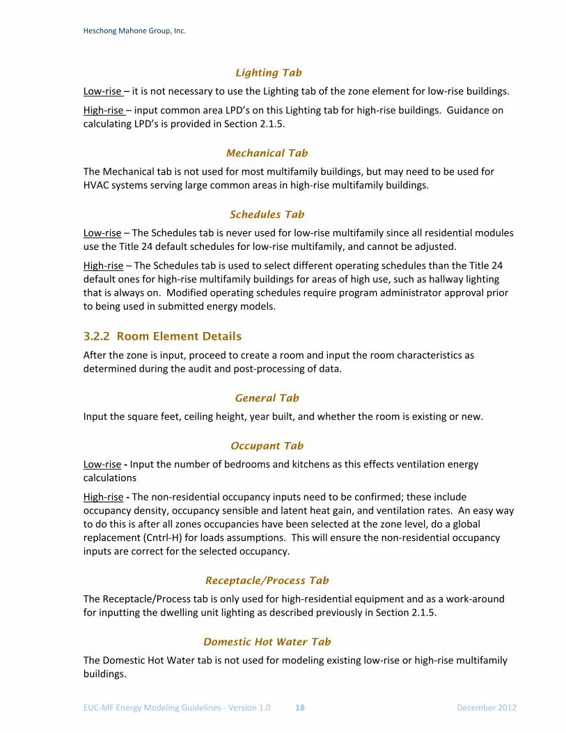
Lighting Tab
Low‐rise – it is not necessary to use the Lighting tab of the zone element for low‐rise buildings.
High‐rise – input common area LPD’s on this Lighting tab for high‐rise buildings. Guidance on calculating LPD’s is provided in Section 2.1.5.
Mechanical Tab
The Mechanical tab is not used for most multifamily buildings, but may need to be used for HVAC systems serving large common areas in high‐rise multifamily buildings.
Schedules Tab
Low‐rise – The Schedules tab is never used for low‐rise multifamily since all residential modules use the Title 24 default schedules for low‐rise multifamily, and cannot be adjusted.
High‐rise – The Schedules tab is used to select different operating schedules than the Title 24 default ones for high‐rise multifamily buildings for areas of high use, such as hallway lighting that is always on. Modified operating schedules require program administrator approval prior to being used in submitted energy models.
3.2.2 Room Element Details
After the zone is input, proceed to create a room and input the room characteristics as determined during the audit and post‐processing of data.
General Tab
Input the square feet, ceiling height, year built, and whether the room is existing or new.
Occupant Tab
Low‐rise ‐ Input the number of bedrooms and kitchens as this effects ventilation energy calculations
High‐rise ‐ The non‐residential occupancy inputs need to be confirmed; these include occupancy density, occupancy sensible and latent heat gain, and ventilation rates. An easy way to do this is after all zones occupancies have been selected at the zone level, do a global replacement (Cntrl‐H) for loads assumptions. This will ensure the non‐residential occupancy inputs are correct for the selected occupancy.
Receptacle/Process Tab
The Receptacle/Process tab is only used for high‐residential equipment and as a work‐around for inputting the dwelling unit lighting as described previously in Section 2.1.5.
Domestic Hot Water Tab
The Domestic Hot Water tab is not used for modeling existing low‐rise or high‐rise multifamily buildings.
Heschong Mahone Group, Inc.
EUC‐MF Energy Modeling Guidelines ‐ Version 1.1 19 December 2012
Exhaust Fan Tab
The Exhaust Fan tab is only used to input exhaust fans in high‐rise residential buildings. The process is described below in Section 6.4.2.
Lighting Tab
The Lighting tab is not used for low‐rise or high‐rise multifamily buildings.
3.3 Exterior Surface Inputs
Exterior surfaces are added to each defined room element and typically include raised floors, slab on grade floors, walls, roofs, and windows.
Gross areas for all exterior surfaces are to be input.
When labeling your exterior walls it is helpful to label by Front, Back, Right, and Left instead of orientation. This is useful if you are creating a mirror image.
A number of construction assemblies have minor distinctions that may not be easy to identify. Some of the nuances of various construction assemblies that you will encounter in EnergyPro are covered in this section.
3.3.1 Default Values
Verification of construction assemblies in an unobtrusive manner may be very difficult, or opposed by the building owner. In these cases, default construction assembly u‐values from Table R3‐50 of the 2008 Residential Compliance Manual shall be used.
3.3.2 Attic and Cathedral Roofs
Determining attic vs. cathedral ceiling:
Attic – an attic roof includes a ventilated space that is greater than 6 inches above the insulation and between the roof.
Cathedral – a cathedral roof is any roof that does not have an attic space less than 6 inches of space. The roof tilt must also be defined for these roof types. A roof tilt of 0 is often termed a flat roof.
3.3.3 Raised Floors
Raised floors can be raised with a crawlspace, raised without a crawlspace, or raised over exterior conditions. The CEC rule is that if the crawlspace is ventilated, the construction is considered ‘raised floor with crawlspace’. If it is anything else it would be considered ‘floor ‐ no crawl space’.
If a raised floor is over a garage or unconditioned basement it should be modeled as a ‘floor ‐ no crawlspace’ because the temperature in the space is at an intermediate condition.
Document your floor selection for ease of assessment review/quality assurance check.
Heschong Mahone Group, Inc.
EUC‐MF Energy Modeling Guidelines ‐ Version 1.0 20 December 2012
3.3.4 Slab on Grade Floors
Slab on grade floor inputs require the floor area, perimeter length, construction assembly, and whether it is new or existing. Always model the slab on grade perimeter that is adjacent to the exterior. Exterior perimeter of the slab is any slab edge that is along the outside of the slab. Select the un‐heated slab construction assembly for slabs except those with radiant heating elements in the slab. In that case, select the heated slab on grade assembly.
Underground Floor is the slab floor of a basement that is below grade. Underground wall is a basement wall or other wall in contact with the soil.
3.3.5 Exterior Walls
Exterior wall inputs require the wall area, surface type, construction assembly, orientation, and tilt. Wall areas can be grouped according to the same orientation as described above in Section 3.1.5. Wall construction assemblies encountered in existing multifamily buildings are typically available in the EnergyPro assembly library.
Shaded Walls
Some walls are completely shaded, yet exposed to ambient conditions. An example is an exterior wall of a dwelling unit adjacent to a unconditioned corridor. The corridor has openings that result in the indoor temperature being relatively that of the ambient conditions, but with a roof that eliminates any solar heat gains.
To model this scenario, model the walls as the actual orientation and create a new wall assembly based on the actual but with an aged solar reflectance of 1.0. This will simulate a wall that reflects 100% of solar gains. Aged solar reflectance is a dimensionless quantity ranging from 0.0 (absorbs all solar radiation) to 1.0 (absorbs no solar radiation). An assembly with this input set to “1.0” therefore results in its surface being modeled as having no solar gain.
3.3.6 Windows and Overhangs
Window inputs require the area, surface type, and construction assembly. In the majority of projects, it is preferred to aggregate window area for all windows on a wall in the same zone when they have the same u‐value, SHGC, and shading characteristics. Separate out individual windows to account for shading, such as overhangs or side fins, or to account for different types of windows (U‐values and SHGC).
Window Assemblies
When selecting a window construction assembly, the U‐value and SHGC are the most important aspects to consider. There are three choices to select from: default, center of glass, and NFRC rating.
When selecting the default values, as most existing building models will use, the energy analyst must also select the appropriate fenestration properties as these affect the default U‐value and SHGC values. It is necessary to create a different window assembly for fixed and operable windows when using the default values.
Heschong Mahone Group, Inc.
EUC‐MF Energy Modeling Guidelines ‐ Version 1.1 21 December 2012
Center of glass values are typically for site built windows used in high‐rise buildings. These values exclude the framing.
NFRC labeled windows are for manufactured windows and include the framing factor. The fenestration properties do not need adjustment when selecting NFRC labeled windows. If this approach is used in the final test‐out models, the NFRC label must be provided as part of the project submittal.
Overhangs, Side-fins, and Other Exterior Shading
Only shading permanently attached to the building should be modeled. A tree or a neighboring building may not be used in the model as shading. Overhangs that extend at least one foot out over the window must be modeled.
Heschong Mahone Group, Inc.
EUC‐MF Energy Modeling Guidelines ‐ Version 1.0 22 December 2012
4. DOMESTIC HOT WATER (DHW) All multifamily buildings will have a domestic hot water (DHW) system to model. The DHW equipment can be individual DHW units per dwelling unit, central DHW systems serving all dwelling units, or a combination of both. The DHW system characteristics are input into EnergyPro on the Domestic Hot Water tab of the Plant element.
Data for these inputs is taken from data collection forms:
Multifamily Building Information Data Collection Form ‐1/3: the second half has MF Central DHW data
Multifamily Dwelling Unit – Equipment Form – 1/2: individual DHW system data
4.1.1 Equipment Efficiency Determination
The following directories can be used to obtain efficiency values: manufacturer specifications, Energy Commission Appliance Directory, AHRI Primenet on‐line directory, or RESNET default vintage tables. Table R3‐50 of the 2008 Residential Compliance Manual shall be used for default values for DHW and HVAC equipment if the efficiency cannot be verified with these directories.
De‐rating of equipment nameplate or default ratings is not allowed for EUC project submittals unless the equipment has been field tested and the actual operating efficiency has been verified.
4.1.2 Domestic Hot Water Inputs
The primary DHW boiler equipment, circulation pump, and hydronic piping are input on the Domestic Hot Water tab.
DHW Boiler
Small storage water heaters and large storage water heaters are typically not considered boilers, but in this section and EnergyPro, the term boiler is interchangeable with the term water heater.
The input rating of a gas‐fired boiler defines whether it is a small or large boiler. Gas fired boilers with an input rating of 75,001 Btu/hr and greater are considered large capacity boilers. Gas‐fired boilers with an input rating of 75,000 Btu/hr and less are considered small capacity water heaters. Both small capacity and large capacity boilers require the storage tank volume and input rating.
Large boilers ‐ The additional inputs for large capacity boilers are the recovery efficiency and standby loss. Large capacity boilers without a verifiable recovery efficiency or standby loss should use 0.76 recovery efficiency and a standby loss of 2.5%. The standby loss is input in decimal format (e.g. 0.025).
Heschong Mahone Group, Inc.
EUC‐MF Energy Modeling Guidelines ‐ Version 1.1 23 December 2012
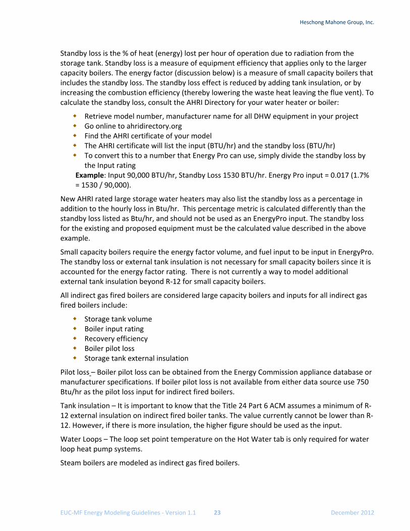
Standby loss is the % of heat (energy) lost per hour of operation due to radiation from the storage tank. Standby loss is a measure of equipment efficiency that applies only to the larger capacity boilers. The energy factor (discussion below) is a measure of small capacity boilers that includes the standby loss. The standby loss effect is reduced by adding tank insulation, or by increasing the combustion efficiency (thereby lowering the waste heat leaving the flue vent). To calculate the standby loss, consult the AHRI Directory for your water heater or boiler:
Retrieve model number, manufacturer name for all DHW equipment in your project Go online to ahridirectory.org Find the AHRI certificate of your model The AHRI certificate will list the input (BTU/hr) and the standby loss (BTU/hr) To convert this to a number that Energy Pro can use, simply divide the standby loss by
the Input rating Example: Input 90,000 BTU/hr, Standby Loss 1530 BTU/hr. Energy Pro input = 0.017 (1.7% = 1530 / 90,000).
New AHRI rated large storage water heaters may also list the standby loss as a percentage in addition to the hourly loss in Btu/hr. This percentage metric is calculated differently than the standby loss listed as Btu/hr, and should not be used as an EnergyPro input. The standby loss for the existing and proposed equipment must be the calculated value described in the above example.
Small capacity boilers require the energy factor volume, and fuel input to be input in EnergyPro. The standby loss or external tank insulation is not necessary for small capacity boilers since it is accounted for the energy factor rating. There is not currently a way to model additional external tank insulation beyond R‐12 for small capacity boilers.
All indirect gas fired boilers are considered large capacity boilers and inputs for all indirect gas fired boilers include:
Storage tank volume Boiler input rating Recovery efficiency Boiler pilot loss Storage tank external insulation
Pilot loss – Boiler pilot loss can be obtained from the Energy Commission appliance database or manufacturer specifications. If boiler pilot loss is not available from either data source use 750 Btu/hr as the pilot loss input for indirect fired boilers.
Tank insulation – It is important to know that the Title 24 Part 6 ACM assumes a minimum of R‐12 external insulation on indirect fired boiler tanks. The value currently cannot be lower than R‐12. However, if there is more insulation, the higher figure should be used as the input.
Water Loops – The loop set point temperature on the Hot Water tab is only required for water loop heat pump systems.
Steam boilers are modeled as indirect gas fired boilers.

Heschong Mahone Group, Inc.
EUC‐MF Energy Modeling Guidelines ‐ Version 1.0 24 December 2012
MF Central DHW Pump and Piping
The “multifamily central systems” check box should be checked if the DHW system serves six or more dwelling units. For MF central DHW systems the recirculation pump and piping characteristics need to be input.
Recirculation Pumps – Input the recirculation pump motor horsepower and quantity of pumps. The horsepower can be obtained off of the nameplate. Typically these are small pumps rated in Watts and will need to be converted to horsepower using the following conversion.
HPpump = Wattspump / 746 Watts per HP
Example: HPpump = 50Wpump / 746 Watts per HP = 0.067 HP
Recirculation pump controls – Describe the recirculation pump control methodology for the multifamily central DHW system. There are several methods to control the recirculation pump. Existing systems commonly run continuously or utilize a timer. The control options for multifamily central DHW recirculation pump include
None: runs continuously (24/7). Timer: time clock that turns on/off during normal use times. Demand: water heating turns on based on hot water demand. Temperature: uses a temperature sensor in the loop; when the temperature drops
below a certain temperature the pump will turn on to recirculate the water. Timer‐temperature: combination of a timer and temperature system.
Distribution piping – The linear feet of DHW distribution piping located outside, underground, and in plenums needs to be input into the model. If the DHW system serves multiple buildings on the property then there will likely be piping located underground. This length will need to be measured from site plans or estimated during the audit.
Residential Distribution Residential distribution is intended to describe the piping within the dwelling units for individual DHW systems and systems serving less than six dwelling units. The default in EnergyPro is Kitchen Pipe Insulation (or “Standard” in the Title 24 Part 6 2008 Residential Compliance Manual, Table 5‐1), defined as a standard system, without any pumps for distributing hot water, in which the first 5 ft of both hot and cold water piping from the storage tank is insulated, as is piping from the water heater to the kitchen. This default likely needs to be changed as determined during the energy audit to either No Pipe Insulation (most likely), or All Pipes Insulated. Other, less common distribution system descriptor options are outlined in Table 5‐1 of the 2008 Residential Compliance Manual.
This input is not required for multifamily central DHW systems.
Heschong Mahone Group, Inc.
EUC‐MF Energy Modeling Guidelines ‐ Version 1.1 25 December 2012
Combined Hydronic Piping
Input characteristics including length, diameter, and insulation thickness of combined hydronic DHW piping in unconditioned space. This input is applicable to serving less than six dwelling units.
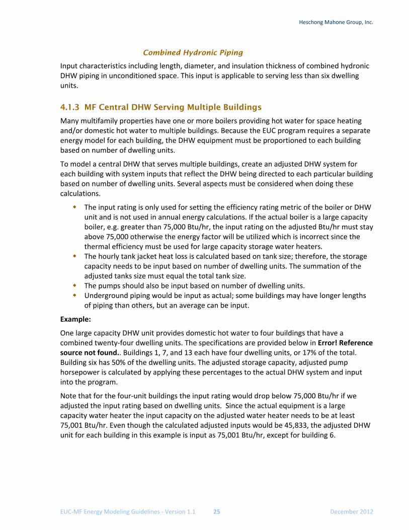
4.1.3 MF Central DHW Serving Multiple Buildings
Many multifamily properties have one or more boilers providing hot water for space heating and/or domestic hot water to multiple buildings. Because the EUC program requires a separate energy model for each building, the DHW equipment must be proportioned to each building based on number of dwelling units.
To model a central DHW that serves multiple buildings, create an adjusted DHW system for each building with system inputs that reflect the DHW being directed to each particular building based on number of dwelling units. Several aspects must be considered when doing these calculations.
The input rating is only used for setting the efficiency rating metric of the boiler or DHW unit and is not used in annual energy calculations. If the actual boiler is a large capacity boiler, e.g. greater than 75,000 Btu/hr, the input rating on the adjusted Btu/hr must stay above 75,000 otherwise the energy factor will be utilized which is incorrect since the thermal efficiency must be used for large capacity storage water heaters.
The hourly tank jacket heat loss is calculated based on tank size; therefore, the storage capacity needs to be input based on number of dwelling units. The summation of the adjusted tanks size must equal the total tank size.
The pumps should also be input based on number of dwelling units. Underground piping would be input as actual; some buildings may have longer lengths
of piping than others, but an average can be input.
Example:
One large capacity DHW unit provides domestic hot water to four buildings that have a combined twenty‐four dwelling units. The specifications are provided below in Error! Reference source not found.. Buildings 1, 7, and 13 each have four dwelling units, or 17% of the total. Building six has 50% of the dwelling units. The adjusted storage capacity, adjusted pump horsepower is calculated by applying these percentages to the actual DHW system and input into the program.
Note that for the four‐unit buildings the input rating would drop below 75,000 Btu/hr if we adjusted the input rating based on dwelling units. Since the actual equipment is a large capacity water heater the input capacity on the adjusted water heater needs to be at least 75,001 Btu/hr. Even though the calculated adjusted inputs would be 45,833, the adjusted DHW unit for each building in this example is input as 75,001 Btu/hr, except for building 6.
Heschong Mahone Group, Inc.
EUC‐MF Energy Modeling Guidelines ‐ Version 1.0 26 December 2012
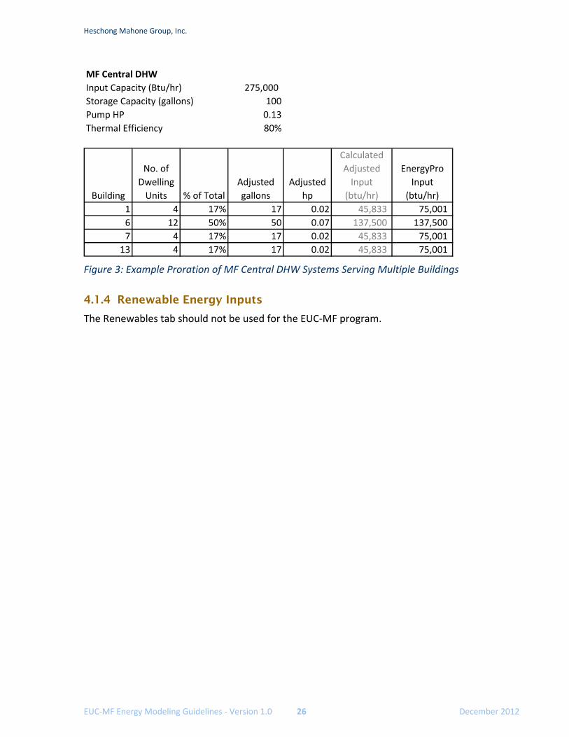
Figure 3: Example Proration of MF Central DHW Systems Serving Multiple Buildings
4.1.4 Renewable Energy Inputs
The Renewables tab should not be used for the EUC‐MF program.
MF Central DHW
Input Capacity (Btu/hr) 275,000
Storage Capacity (gallons) 100
Pump HP 0.13
Thermal Efficiency 80%
Building
No. of
Dwelling
Units % of Total
Adjusted
gallons
Adjusted
hp
Calculated
Adjusted
Input
(btu/hr)
EnergyPro
Input
(btu/hr)
1 4 17% 17 0.02 45,833 75,001
6 12 50% 50 0.07 137,500 137,500
7 4 17% 17 0.02 45,833 75,001
13 4 17% 17 0.02 45,833 75,001
Heschong Mahone Group, Inc.
EUC‐MF Energy Modeling Guidelines ‐ Version 1.1 27 December 2012
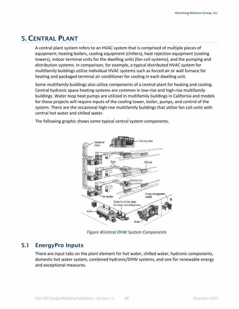
5. CENTRAL PLANT A central plant system refers to an HVAC system that is comprised of multiple pieces of equipment; heating boilers, cooling equipment (chillers), heat rejection equipment (cooling towers), indoor terminal units for the dwelling units (fan coil systems), and the pumping and distribution systems. In comparison, for example, a typical distributed HVAC system for multifamily buildings utilize individual HVAC systems such as forced air or wall furnace for heating and packaged terminal air conditioner for cooling in each dwelling unit.
Some multifamily buildings also utilize components of a central plant for heating and cooling. Central hydronic space heating systems are common in low‐rise and high‐rise multifamily buildings. Water loop heat pumps are utilized in multifamily buildings in California and models for these projects will require inputs of the cooling tower, boiler, pumps, and control of the system. There are the occasional high‐rise multifamily buildings that utilize fan coil units with central hot water and chilled water.
The following graphic shows some typical central system components.
Figure 4Central DHW System Components
5.1 EnergyPro Inputs
There are input tabs on the plant element for hot water, chilled water, hydronic components, domestic hot water system, combined hydronic/DHW systems, and one for renewable energy and exceptional measures.
Heschong Mahone Group, Inc.
EUC‐MF Energy Modeling Guidelines ‐ Version 1.0 28 December 2012
5.1.1 Heating Hot Water Tab
The Heating Hot Water” tab is used to input the boiler and distribution characteristics of central space heating systems using a central hot water boiler that circulates hot water to terminal units located in the dwelling units. Examples of central hot water heating system types utilized in multifamily buildings include radiant baseboards and fan coil units. The primary boiler equipment, hot water pump, and hydronic piping are input on the Heating Hot Water tab of plant element.
Hot Water Boiler
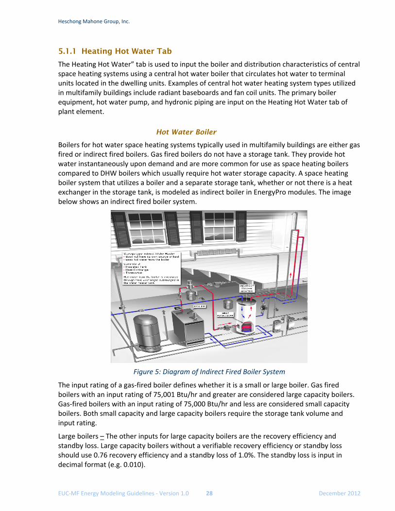
Boilers for hot water space heating systems typically used in multifamily buildings are either gas fired or indirect fired boilers. Gas fired boilers do not have a storage tank. They provide hot water instantaneously upon demand and are more common for use as space heating boilers compared to DHW boilers which usually require hot water storage capacity. A space heating boiler system that utilizes a boiler and a separate storage tank, whether or not there is a heat exchanger in the storage tank, is modeled as indirect boiler in EnergyPro modules. The image below shows an indirect fired boiler system.
Figure 5: Diagram of Indirect Fired Boiler System
The input rating of a gas‐fired boiler defines whether it is a small or large boiler. Gas fired boilers with an input rating of 75,001 Btu/hr and greater are considered large capacity boilers. Gas‐fired boilers with an input rating of 75,000 Btu/hr and less are considered small capacity boilers. Both small capacity and large capacity boilers require the storage tank volume and input rating.
Large boilers – The other inputs for large capacity boilers are the recovery efficiency and standby loss. Large capacity boilers without a verifiable recovery efficiency or standby loss should use 0.76 recovery efficiency and a standby loss of 1.0%. The standby loss is input in decimal format (e.g. 0.010).
Heschong Mahone Group, Inc.
EUC‐MF Energy Modeling Guidelines ‐ Version 1.1 29 December 2012
Small capacity boilers require the energy factor to be input, in addition to volume and input. The standby loss is not necessary for small capacity boilers since it is accounted for in the energy factor rating.
All indirect gas fired boilers are considered large capacity boilers and inputs for all indirect gas fired boilers include:
Storage tank volume Boiler input rating Recovery efficiency Boiler pilot loss Storage tank external insulation
Boiler pilot loss can be obtained from the Energy Commission appliance database or manufacturer specifications. If boiler pilot loss is not available from either data source, use 750 Btu/hr as the pilot loss input for indirect fired boilers.
Boiler Tank Insulation – It is important to know that the Title 24 Part 6 ACM assumes a minimum of R‐12 external insulation on indirect fired boiler tanks. The value currently cannot be lower than R‐12, however, if there is more insulation such as R‐16 this can be input.
Water loops – The loop set point temperature on the Heating Hot Water tab is only required for water loop heat pump systems. At the current time the supply hot water temperature cannot be changed and it is assumed to be 180°F for hot water boilers and steam boilers.
Steam boilers are modeled as indirect gas fired boilers.
Hot Water Pump
There are no vintage defaults for hot water pumping systems.
Pump flow rate – The hot water pump flow rate (gpm) is not a critical input, however it should be input into the software and can usually be obtained from plans or the pump nameplate information. The pump design horsepower is more important to ensure an accurate model. The flow control should be modeled as verified in the field. It is expected that many hot water pumps in existing multifamily buildings are one‐speed pumps with 3‐way valves.
Hydronic Piping
The hydronic piping should have inputs for any piping located in unconditioned space. The software assumes ten feet of piping is in unconditioned space. Therefore, inputs are only required if more than ten feet of the space heating hot water piping is located in unconditioned spaces.
5.1.2 Chilled Water Tab
The Chilled Water tab is only used when there are one or more chillers used for air conditioning the building. The chiller can be air‐cooled or water cooled, in which case there will also be a cooling tower. Air‐cooled chillers have the compressors and condenser fans in one piece of equipment.
Heschong Mahone Group, Inc.
EUC‐MF Energy Modeling Guidelines ‐ Version 1.0 30 December 2012
Nameplate data needs to be collected. Flow rate needs to be obtained in the field during the audit from pump nameplate information or mechanical schedule on building plans if available.
Operating conditions should also be verified to avoid excessive use of default values.
Chilled water flow rates, control, and leaving temperature need to be field verified or obtained from the mechanical schedules.
Condenser water flow rates, control, and entering water temperature need to be field verified or obtained from the mechanical schedules.
For any project using chillers it is highly recommended that the rater coordinate with HMG prior to completing the energy audit to ensure all required data is collected.
5.1.3 Hydronic Tab
The Hydronic tab is used to define the cooling tower and condenser water pumps for any system served by a water cooled chiller or for a water loop heat pump system.
Specifications and operating conditions of the cooling tower typically need to be obtained from plans and from direct observation during the audit.
Flow rate can be obtained in the field during the audit from pump nameplate information or mechanical schedule on building plans if available.
Heschong Mahone Group, Inc.
EUC‐MF Energy Modeling Guidelines ‐ Version 1.1 31 December 2012
6. HVAC SYSTEMS The HVAC equipment covered in this section focuses on the indoor HVAC units located in the dwelling units and covers the following system types. These system types should be selected based on the type of the cooling system installed. If cooling is not installed the system type does not matter.
Forced air furnace with split DX air conditioner Forced air furnace with no cooling Wall furnace: fan assisted or gravity Radiant heating (baseboard, ceiling panel): hot water, electric, natural gas Split heat pump Package Terminal Air Conditioner (PTAC) Package Terminal heat pump (PTHP) Water‐loop heat pumps
6.1 Organizing Audit Data for Input
6.1.1 Multipliers and Combining like Systems
Utilize the multiplier to model more than one of the same equipment. For example, a MF building has twenty dwelling units and each dwelling unit has the same type of wall furnace. Create and define the wall furnace in EnergyPro, assign a multiplier of twenty to this system, then create and assign the dwelling unit zones to this system you created.
If there are multiple system types serving the building, create a system in EnergyPro for each unique HVAC system and assign the zones served by each unique HVAC system.
Example:
A multifamily building consists of two levels with eight dwelling units on each floor. The first floor utilizes wall furnaces, and the second floor is served by forced air furnace with ducted distribution. Wall furnaces and forced air furnaces are two different system types and need to be modeled separately. Create a system for furnaces and assign the dwelling units served by the furnaces to this system. Do the same for the wall furnaces and dwelling units served by wall furnaces.
6.1.2 Equipment Efficiency Determination
The following directories can be used to obtain efficiency values: manufacturer specifications, Energy Commission Appliance Directory, AHRI Primenet on‐line directory, or RESNET default vintage tables. Table R3‐50 of the 2008 Residential Compliance Manual shall be used for default values for DHW and HVAC equipment if the efficiency cannot be verified with these directories.
De‐rating of equipment nameplate or default ratings is not allowed for EUC project submittals unless the equipment has been field tested and the actual operating efficiency has been verified.
Heschong Mahone Group, Inc.
EUC‐MF Energy Modeling Guidelines ‐ Version 1.0 32 December 2012
6.2 EnergyPro HVAC System Inputs
The General, Distribution, and Residential tabs on the HVAC System element are the primary fields for data input of existing multifamily building HVAC systems. The HERS tab and MECH‐2 tabs are used for Title 24 Part 6 compliance documentation of new construction projects.
6.2.1 General Tab and HVAC System Definition
The General tab is used to define the HVAC system and assign a multiplier to the system. The other items on the General tab are typically not used for existing multifamily buildings.
Existing systems found in multifamily buildings are not likely to found in the default EnergyPro library. In these situations the modeler will need to create a new HVAC system in the EnergyPro library. When creating or modifying an existing library item, the following sections must be defined based on actual system characteristics.
There is no need for the modeler to modify any EnergyPro data pertaining to the HVAC system besides the information on the Heating, Cooling, and Fans tabs of the actual piece of equipment. Inputs on the Controls, Outdoor Air, and Curves tabs do not change the energy results in a low‐rise project; any modifications to these fields are not evaluated by EnergyPro.
HVAC System Heating
The system type selection on the Heating tab of the HVAC system library component is used to define the HVAC system type. In effect, the system type selection describes the cooling system installed. EnergyPro automatically enables applicable inputs for cooling and heating depending on the system type selected.
Example:
Selecting split DX allows the user to select the heating type, which can be gas furnace, electric resistance, heat pump, or hot water. Since a four‐pipe fan coil unit always uses hot and chilled water, selecting four‐pipe fan coil as the system type disallows the user from changing the heating and cooling types from hot water and chilled water.
The HVAC systems installed in existing multifamily buildings will most likely be modeled in EnergyPro as one of the following system types.
Split DX: used for split air conditioners (compressors are outside or on the roof), split heat pumps, and for all furnaces including forced air furnaces and wall furnaces
Room PTAC: used for all through‐the‐wall and window‐type air conditioners and all through‐the‐wall and window‐type heat pumps
Hydronic Heat Pump: central heat pumps which utilize a cooling tower for heat rejection and a boiler for supplemental heating
Four‐pipe Fan Coil: used for fan coil units served by central boilers and chillers Evaporative Cooler: used for evaporative cooling systems
Heschong Mahone Group, Inc.
EUC‐MF Energy Modeling Guidelines ‐ Version 1.1 33 December 2012
The heating type is defined after the system type is selected and will be one of the following heating types:
Gas furnace: used for all furnace types Electric resistance: used for electric wall panels, ceiling panels, baseboards, and electric
furnaces Heat pump: used for PTHP, split heat pump, and packaged heat pumps Hot Water: used for wall hot water space heating systems Gas heat pump: un‐likely system for multifamily buildings
The furnace type must be selected when gas furnace is selected as heating type. Furnace options include central furnace, wall furnace with fan, wall furnace without fan, floor furnace, or portable room furnace. Distribution characteristics will need to be defined based on furnace type selection.
The heating output is based on information from the energy audit and will likely be based on equipment nameplate data. While a required input, the heating capacity total output does not affect the energy modeling results for low‐rise multifamily projects. The program assumes the heating capacity meets the heating loads and does not penalize for an over‐sized or under‐sized system. The heating capacity does affect the results of high‐rise residential multifamily buildings.
System efficiency is based on the system nameplate data and system type.
Annual Fuel Use Efficiency (AFUE): used for all gas furnaces Heating Seasonal Performance Factor (HSPF): used for electric resistance heating and
split heat pumps. Electric resistance heating efficiency is modeled as 3.413 HSPF. The heat pump efficiency rating may need to be converted from COP to HSPF.
Coefficient of Performance (COP): used for packaged terminal heat pump heating efficiency
The pre‐heat coils, re‐heat coils, and baseboard heat inputs are not required for the heating system types described above.
HVAC System Cooling
On the Cooling tab of the HVAC system library component, input the total cooling output and sensible cooling output based on cooling equipment nameplate data. If the sensible cooling output cannot be confirmed through manufacturer specifications, multiplying the total cooling output by 0.70 to obtain the sensible cooling output is acceptable.
To model a ‘heating only’ system, also referred to as a system with no cooling, the total and sensible cooling output must be input as zero. This is required for EnergyPro to know that there is no cooling installed.
The cooling efficiency metric depends on the type and total capacity of the cooling equipment.
Packaged and split air conditioners and heat pumps with a cooling capacity less than 65,000 Btu/hr. (5.42 tons) use the SEER efficiency rating.
Packaged and split air conditioners and heat pump with cooling capacity 65,000 Btu/hr and greater use the EER rating as the cooling efficiency rating.
Heschong Mahone Group, Inc.
EUC‐MF Energy Modeling Guidelines ‐ Version 1.0 34 December 2012
Water loop heat pumps use the EER rating for cooling efficiency. All PTAC and PTHP systems use the EER rating for cooling efficiency.
Cooling supply air temperature input is not required for distributed cooling HVAC equipment (packaged and split systems) typically used in multifamily buildings.
No Cooling, Modeled as Standard Cooling
All buildings are modeled with standard efficiency cooling systems whether or not there is air‐conditioning installed in the building. The reasoning behind this requirement is that the envelope characteristics, such as window types and insulation levels, affect the cooling load of the building. A tenant may install air conditioning in a dwelling unit that previously did not have air conditioning, which is a growing trend in coastal as well as inland areas of the state. In addition, by including the cooling we get a uniform rating of all homes.
The need for post‐processing of results related to this modeling of non‐existent cooling systems only applies to TDV EnergyPro results from the CalRatePro module.
Projects pursuing SDG&E incentives use site energy to qualify for the programs and to set incentive levels. With projects that do not have cooling systems, EnergyPro removes the cooling energy from reported results at the bottom of EnergyPro screen and on the ECON‐2 reports. Therefore, post‐processing the cooling energy is not required when reporting site energy.
HVAC System Controls
The Controls tab of the HVAC System library component describes the HVAC system fan operation as continuous or intermittent. System fans typically cycle on and off with a call for heating or cooling as opposed to running continuously regardless of heating or cooling demand.
Low‐rise – Intermittent fan operation is assumed for low‐rise multifamily projects and changing to continuous operation does not change the results of the model.
High‐rise – residential projects utilize the nonresidential modules of EnergyPro and fan control is a required input for models run using the non‐residential module. However, fans in high‐rise residential must be modeled as continuous. The simulation results may not be accurate if intermittent is used due to simulation engine bug with the intermittent fan operation.
The other control inputs are not required, and do not affect the simulation results for multifamily HVAC system types. These are the cycling on at night to meet loads, DDC controls to the zone level, and fault diagnostic options.
HVAC System Outdoor Air
The Outdoor Air tab is used to define economizer types for packaged HVAC equipment serving nonresidential and high‐rise multifamily buildings.
Exhaust air heat recovery inputs may be required if there is a heat recovery system installed on the exhaust air streams for high‐rise residential projects.
Heschong Mahone Group, Inc.
EUC‐MF Energy Modeling Guidelines ‐ Version 1.1 35 December 2012
HVAC System Fans
The Fans tab is used to define the supply and return fans in all HVAC systems serving low‐rise and high‐rise multifamily buildings. Fan power (hp) and fan flow (cfm) must be input based on nameplate data and/or manufacturer specifications.
Default air flow can be calculated as 400 cfm per ton of cooling or 21.7 cfm per thousand Btu/hr of heating capacity.
Hot water and electric radiant systems and gravity wall furnaces will not have fans to enter.
HVAC System Evaporative Cooling
Evaporative cooling systems are unlikely to be installed in multifamily buildings and are not covered in these energy modeling guidelines.
6.2.2 Distribution Tab
The Distribution tab system element is used to input the heating and cooling distribution characteristics of the HVAC system defined on the General Tab.
Heating Distribution
Heating distribution is used to select the type of heating distribution: ducted, ductless with fan, ductless w/out fan, radiant floor, or baseboard.
Cooling Distribution
Cooling distribution is used to select a ducted or ductless cooling distribution system. Ducted is typical forced air furnace with air‐conditioning. Ductless would be for a PTAC, PTHP, WLHP, or fan coil unit
Duct Location and Insulation:
Duct location is used to select the location of the distribution ducts. Ducts in conditioned space refer to ducts that are within the thermal barrier, AND in space that is heated or cooled. Ducts that are located in an attic that is insulated in one of several methods, but not conditioned, are not considered to be in conditioned space.
Input the verified duct insulation R‐value.
Duct Leakage HERS Credits
Credit for duct distribution HERS measures that are required due to equipment change‐out cannot be claimed for EUC project submittals. These include:
Sealed ducts with leakage verified: EnergyPro assumes 15% leakage Low Leakage AHU or HERS Verified: technically this is leakage to the outside. If
performing a standard duct test at test‐in (duct blaster only, without blower door), put half the measured value into the model. The assumption is that half of the duct leakage is to outside. If the duct leakage to outside is measured (with a duct blaster and blower
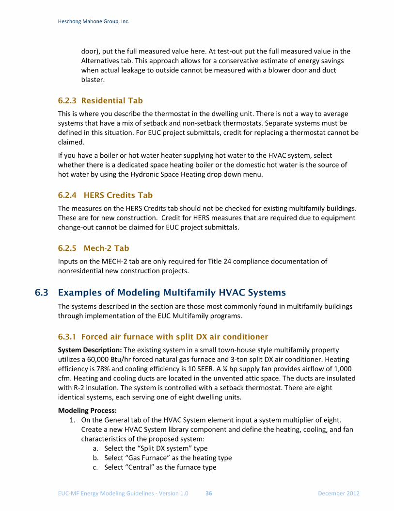
Heschong Mahone Group, Inc.
EUC‐MF Energy Modeling Guidelines ‐ Version 1.0 36 December 2012
door), put the full measured value here. At test‐out put the full measured value in the Alternatives tab. This approach allows for a conservative estimate of energy savings when actual leakage to outside cannot be measured with a blower door and duct blaster.
6.2.3 Residential Tab
This is where you describe the thermostat in the dwelling unit. There is not a way to average systems that have a mix of setback and non‐setback thermostats. Separate systems must be defined in this situation. For EUC project submittals, credit for replacing a thermostat cannot be claimed.
If you have a boiler or hot water heater supplying hot water to the HVAC system, select whether there is a dedicated space heating boiler or the domestic hot water is the source of hot water by using the Hydronic Space Heating drop down menu.
6.2.4 HERS Credits Tab
The measures on the HERS Credits tab should not be checked for existing multifamily buildings. These are for new construction. Credit for HERS measures that are required due to equipment change‐out cannot be claimed for EUC project submittals.
6.2.5 Mech-2 Tab
Inputs on the MECH‐2 tab are only required for Title 24 compliance documentation of nonresidential new construction projects.
6.3 Examples of Modeling Multifamily HVAC Systems
The systems described in the section are those most commonly found in multifamily buildings through implementation of the EUC Multifamily programs.
6.3.1 Forced air furnace with split DX air conditioner
System Description: The existing system in a small town‐house style multifamily property utilizes a 60,000 Btu/hr forced natural gas furnace and 3‐ton split DX air conditioner. Heating efficiency is 78% and cooling efficiency is 10 SEER. A ¼ hp supply fan provides airflow of 1,000 cfm. Heating and cooling ducts are located in the unvented attic space. The ducts are insulated with R‐2 insulation. The system is controlled with a setback thermostat. There are eight identical systems, each serving one of eight dwelling units.
Modeling Process: 1. On the General tab of the HVAC System element input a system multiplier of eight.
Create a new HVAC System library component and define the heating, cooling, and fan characteristics of the proposed system:
a. Select the “Split DX system” type b. Select “Gas Furnace” as the heating type c. Select “Central” as the furnace type
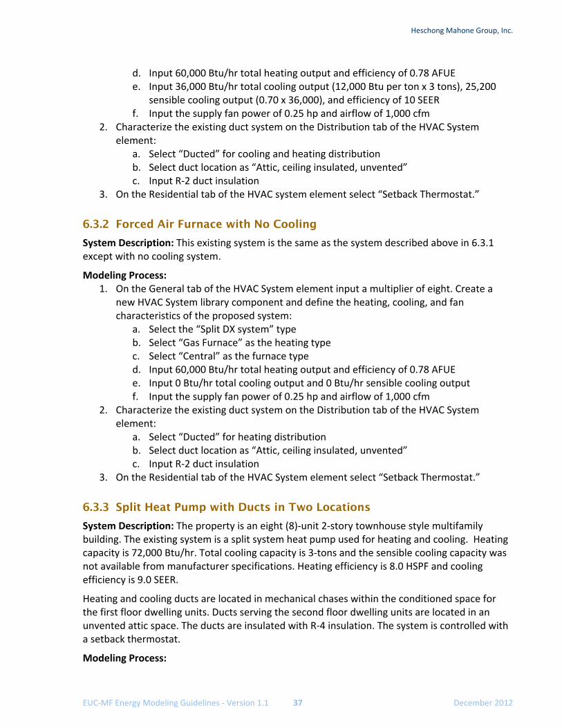
Heschong Mahone Group, Inc.
EUC‐MF Energy Modeling Guidelines ‐ Version 1.1 37 December 2012
d. Input 60,000 Btu/hr total heating output and efficiency of 0.78 AFUE e. Input 36,000 Btu/hr total cooling output (12,000 Btu per ton x 3 tons), 25,200
sensible cooling output (0.70 x 36,000), and efficiency of 10 SEER f. Input the supply fan power of 0.25 hp and airflow of 1,000 cfm
2. Characterize the existing duct system on the Distribution tab of the HVAC System element:
a. Select “Ducted” for cooling and heating distribution b. Select duct location as “Attic, ceiling insulated, unvented” c. Input R‐2 duct insulation
3. On the Residential tab of the HVAC system element select “Setback Thermostat.”
6.3.2 Forced Air Furnace with No Cooling
System Description: This existing system is the same as the system described above in 6.3.1 except with no cooling system.
Modeling Process: 1. On the General tab of the HVAC System element input a multiplier of eight. Create a
new HVAC System library component and define the heating, cooling, and fan characteristics of the proposed system:
a. Select the “Split DX system” type b. Select “Gas Furnace” as the heating type c. Select “Central” as the furnace type d. Input 60,000 Btu/hr total heating output and efficiency of 0.78 AFUE e. Input 0 Btu/hr total cooling output and 0 Btu/hr sensible cooling output f. Input the supply fan power of 0.25 hp and airflow of 1,000 cfm
2. Characterize the existing duct system on the Distribution tab of the HVAC System element:
a. Select “Ducted” for heating distribution b. Select duct location as “Attic, ceiling insulated, unvented” c. Input R‐2 duct insulation
3. On the Residential tab of the HVAC System element select “Setback Thermostat.”
6.3.3 Split Heat Pump with Ducts in Two Locations
System Description: The property is an eight (8)‐unit 2‐story townhouse style multifamily building. The existing system is a split system heat pump used for heating and cooling. Heating capacity is 72,000 Btu/hr. Total cooling capacity is 3‐tons and the sensible cooling capacity was not available from manufacturer specifications. Heating efficiency is 8.0 HSPF and cooling efficiency is 9.0 SEER.
Heating and cooling ducts are located in mechanical chases within the conditioned space for the first floor dwelling units. Ducts serving the second floor dwelling units are located in an unvented attic space. The ducts are insulated with R‐4 insulation. The system is controlled with a setback thermostat.
Modeling Process:
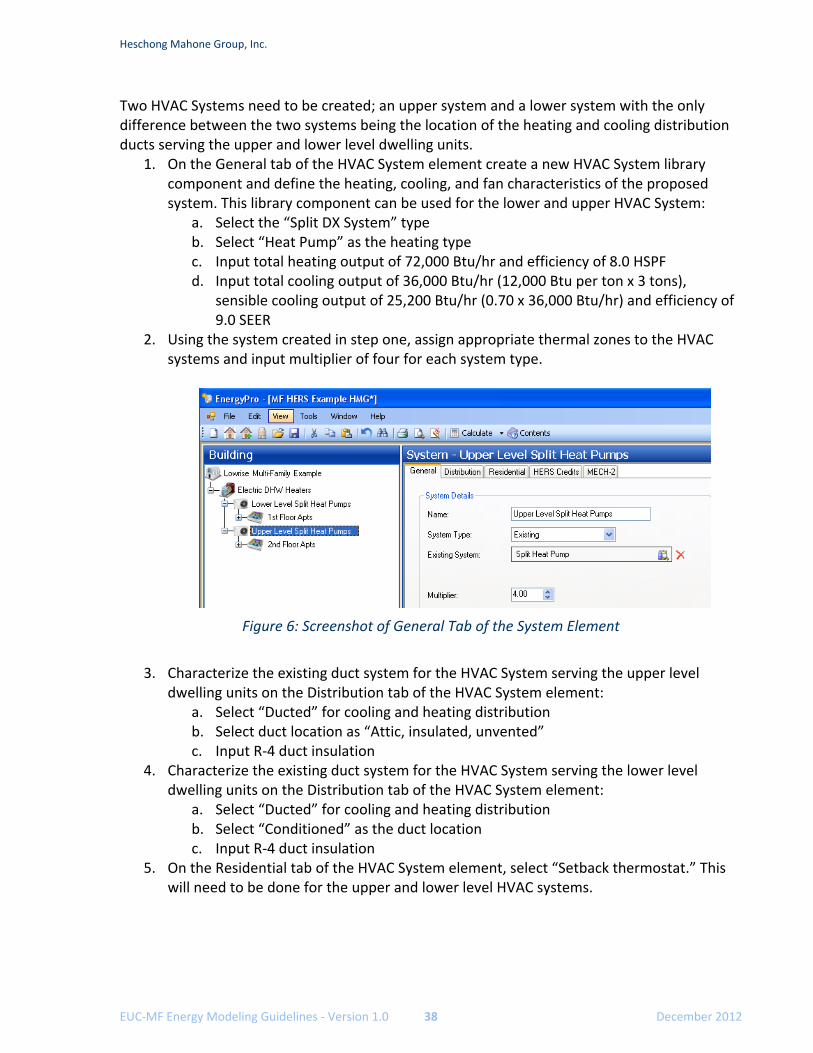
Heschong Mahone Group, Inc.
EUC‐MF Energy Modeling Guidelines ‐ Version 1.0 38 December 2012
Two HVAC Systems need to be created; an upper system and a lower system with the only difference between the two systems being the location of the heating and cooling distribution ducts serving the upper and lower level dwelling units.
1. On the General tab of the HVAC System element create a new HVAC System library component and define the heating, cooling, and fan characteristics of the proposed system. This library component can be used for the lower and upper HVAC System:
a. Select the “Split DX System” type b. Select “Heat Pump” as the heating type c. Input total heating output of 72,000 Btu/hr and efficiency of 8.0 HSPF d. Input total cooling output of 36,000 Btu/hr (12,000 Btu per ton x 3 tons),
sensible cooling output of 25,200 Btu/hr (0.70 x 36,000 Btu/hr) and efficiency of 9.0 SEER
2. Using the system created in step one, assign appropriate thermal zones to the HVAC systems and input multiplier of four for each system type.
Figure 6: Screenshot of General Tab of the System Element
3. Characterize the existing duct system for the HVAC System serving the upper level
dwelling units on the Distribution tab of the HVAC System element: a. Select “Ducted” for cooling and heating distribution b. Select duct location as “Attic, insulated, unvented” c. Input R‐4 duct insulation
4. Characterize the existing duct system for the HVAC System serving the lower level dwelling units on the Distribution tab of the HVAC System element:
a. Select “Ducted” for cooling and heating distribution b. Select “Conditioned” as the duct location c. Input R‐4 duct insulation
5. On the Residential tab of the HVAC System element, select “Setback thermostat.” This will need to be done for the upper and lower level HVAC systems.
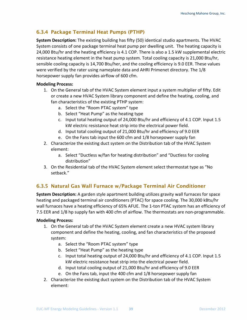
Heschong Mahone Group, Inc.
EUC‐MF Energy Modeling Guidelines ‐ Version 1.1 39 December 2012
6.3.4 Package Terminal Heat Pumps (PTHP)
System Description: The existing building has fifty (50) identical studio apartments. The HVAC System consists of one package terminal heat pump per dwelling unit. The heating capacity is 24,000 Btu/hr and the heating efficiency is 4.1 COP. There is also a 1.5 kW supplemental electric resistance heating element in the heat pump system. Total cooling capacity is 21,000 Btu/hr, sensible cooling capacity is 14,700 Btu/her, and the cooling efficiency is 9.0 EER. These values were verified by the rater using nameplate data and AHRI Primenet directory. The 1/8 horsepower supply fan provides airflow of 600 cfm.
Modeling Process: 1. On the General tab of the HVAC System element input a system multiplier of fifty. Edit
or create a new HVAC System library component and define the heating, cooling, and fan characteristics of the existing PTHP system:
a. Select the “Room PTAC system” type b. Select “Heat Pump” as the heating type c. Input total heating output of 24,000 Btu/hr and efficiency of 4.1 COP. Input 1.5
kW electric resistance heat strip into the electrical power field. d. Input total cooling output of 21,000 Btu/hr and efficiency of 9.0 EER e. On the Fans tab input the 600 cfm and 1/8 horsepower supply fan
2. Characterize the existing duct system on the Distribution tab of the HVAC System element:
a. Select “Ductless w/fan for heating distribution” and “Ductless for cooling distribution”
3. On the Residential tab of the HVAC System element select thermostat type as “No setback.”
6.3.5 Natural Gas Wall Furnace w/Package Terminal Air Conditioner
System Description: A garden style apartment building utilizes gravity wall furnaces for space heating and packaged terminal air conditioners (PTAC) for space cooling. The 30,000 kBtu/hr wall furnaces have a heating efficiency of 65% AFUE. The 1‐ton PTAC system has an efficiency of 7.5 EER and 1/8 hp supply fan with 400 cfm of airflow. The thermostats are non‐programmable.
Modeling Process: 1. On the General tab of the HVAC System element create a new HVAC system library
component and define the heating, cooling, and fan characteristics of the proposed system:
a. Select the “Room PTAC system” type b. Select “Heat Pump” as the heating type c. Input total heating output of 24,000 Btu/hr and efficiency of 4.1 COP. Input 1.5
kW electric resistance heat strip into the electrical power field. d. Input total cooling output of 21,000 Btu/hr and efficiency of 9.0 EER e. On the Fans tab, input the 400 cfm and 1/8 horsepower supply fan
2. Characterize the existing duct system on the Distribution tab of the HVAC System element:
Heschong Mahone Group, Inc.
EUC‐MF Energy Modeling Guidelines ‐ Version 1.0 40 December 2012
a. Select “Ductless w/out fan” for heating distribution, and “Ductless” for cooling distribution
3. On the Residential tab of the HVAC System element select “no setback as the thermostat type
6.3.6 Natural Gas Wall Furnace with Split DX Cooling
System Description: The existing heating system in a small townhouse style multifamily property utilizes fan powered wall furnaces for heating. There are two furnaces in each dwelling unit and there are a total of 15 dwelling units. The heating capacity is 55,000 Btu/hr per system and the heating AFUE is 60%.
Several years after construction, due to overheating complaints, a ducted central split air conditioner was installed in each unit. The 3‐ton split DX air conditioner has an efficiency of 10.8 SEER, a 0.17 hp supply fan with airflow capacity of 1,000 cfm. Cooling ducts are insulated with R‐4 insulation and are located in mechanical chases in the conditioned space. The cooling system is controlled with a setback thermostat.
Modeling Process: 1. On the General tab of the HVAC System element input a multiplier of fifteen since there
are fifteen dwelling units and fifteen air conditioners. The heating capacities of the two wall furnaces should be doubled. Create a new HVAC System library component and define the heating, cooling, and fan characteristics of the proposed system:
a. Select the “Split DX system” type b. Select “Gas Furnace” as the heating type c. Select “Fan Wall” as the furnace type d. Input total heating output of 110,000 Btu/hr and 0.60 AFUE as the efficiency e. Input total cooling output of 36,000 Btu/hr (12,000 Btu per ton x 3 tons)and 10.8
SEER as the efficiency f. Input the fan power as 0.17 hp and flow rate as 1,000 cfm
2. Characterize the existing duct system on the Distribution tab of the HVAC System element:
a. Select “Ducted” for cooling distribution and “Ductless w/fan” for heating distribution
b. Select “Conditioned” as the duct location c. Input R‐4 duct insulation
3. On the Residential tab of the HVAC System element select “Setback thermostat.”
6.3.7 Natural Gas Wall Furnace with No Cooling
System Description: The existing heating system in a small townhouse style multifamily property is a gravity wall furnace. There are two furnaces in each dwelling unit and there are a total of 15 dwelling units. The heating capacity is 55,000 Btu/hr per system and the heating AFUE is 60%.
Modeling Process: 1. On the General tab of the HVAC System element input a multiplier of thirty since there
are fifteen dwelling units with two heaters per dwelling unit. Create a new HVAC System
Heschong Mahone Group, Inc.
EUC‐MF Energy Modeling Guidelines ‐ Version 1.1 41 December 2012
library component and define the heating, cooling, and fan characteristics of the proposed system:
a. Select the “Split DX system” type b. Select “Gas Furnace” as the heating type c. Select “Fan Wall” as the furnace type d. Input 55,000 Btu/hr total heating output and as the efficiency e. Input 0 total cooling and 0 sensible cooling output f. Input 0 for fan power and fan flow rate
2. Characterize the existing duct system on the Distribution tab of the HVAC System element:
a. Select “Ductless” for heating distribution 3. On the Residential tab of the HVAC System element select “Setback thermostat.”
6.3.8 Electric Resistance Radiant Systems
System Description: The existing heating system in a high rise residential building is two 8’ electric resistance radiant baseboards per dwelling unit. Electric radiant baseboards typically consume 250 Watts per linear feet. The conversion from Watts to Btu is 3.413 Btu per Watt. The 8’ electric resistance baseboard has a capacity of 8 linear feet x 250 W/linear feet x 3.413 Btu/W = 6,826 Btu. 100% of electrical energy input into electric resistance is converted to heat; therefore the efficiency is 3.413 HSPF.
There is also one PTAC unit for cooling in each dwelling unit. The PTAC has a cooling capacity of 1‐ton, an efficiency of 8.0 EER, and a 1/8 hp supply fan with airflow of 350 cfm. There is not a setback thermostat and the PTAC fans only run when there is a call for cooling.
Modeling Process: 1. Create a new HVAC System library component and define the heating, cooling, and fan
characteristics of the proposed system: a. Select the “Room PTAC” system type b. Select “Electric Resistance” as the heating type c. Input 6,826 Btu/hr total heating output and 3.413 HSPF as the efficiency d. Input 12,000 Btu/hr total cooling output, 8,400 Btu/hr (0.70 x 12,000) sensible
cooling output, and 8.9 EER cooling efficiency e. Input 0.125 hp for fan power and fan flow rate of 350 cfm f. Since this is a high‐rise project, set the fan controls to “intermittent”
2. Characterize the existing duct system on the Distribution tab of the HVAC System element:
a. Select “Baseboard” for heating distribution and “Ductless” for cooling distribution
3. On the Residential tab of the HVAC System element select “Setback thermostat.”
6.3.9 Low-Rise MF Hot Water Heating Systems – Dedicated Hydronic Boiler
System Description: The existing heating system is hydronic heating system. There is a dedicated central boiler providing hot water to radiant baseboards.
Heschong Mahone Group, Inc.
EUC‐MF Energy Modeling Guidelines ‐ Version 1.0 42 December 2012
The mechanical plans were available and indicated a heating capacity of 18,000 Btu/hr per baseboard.
The gas‐fired boiler has a total capacity of 800,000 Btu/hr and a thermal efficiency of 78%. The standby loss could not be verified from certified equipment directories so the default of 2.5% needs to be used. There is no storage tank. A 0.5 horsepower pump with 200 gpm flow rate was verified on‐site. The pump is one speed. There are approximately 200 linear feet of measured hydronic piping located in the unconditioned parking garage on the first level.
Modeling Process: 1. Define the hot water heating boiler, hot water pump, and hydronic piping on the
Heating Hot Water tab of the Plant element: a. Create a boiler, or edit an existing one, in the EnergyPro library. Input 0 gallons
for storage capacity, 800,000 Btu/hr input, 0.78 recovery efficiency, and .025 standby loss.
b. Input the hot water pump flow rate of 200 gpm, power input of 0.5 horsepower, and select the control as “one speed/three way valves.”
c. Input 200’ for the hydronic pipe length 2. Create a new HVAC System library component and define the heating, cooling, and fan
characteristics of the proposed system: a. Select the “Split DX” system type b. Select “Hot Water” as the heating type c. Input 18,000 Btu/hr total heating output. Efficiency is not needed since the
heating hot water boiler efficiency has been defined. d. Input 0 Btu/hr total cooling output, 0 Btu/hr sensible cooling output to model
this system with no cooling 3. Characterize the existing duct system on the Distribution tab of the HVAC System
element: a. Select “baseboard” for heating distribution
4. On the Residential tab of the HVAC System element connect the space heating boiler defined in step one to the radiant baseboards created in step two by selecting “Heating Boiler Provides Heat for the hydronic space heating” input.
6.3.10 Low-rise MF Hot Water Heating Systems – Combined Hydronic
System Description: The existing heating system is identical to the Low‐Rise MF Hot Water Heating Systems – Dedicated Hydronic Boiler example except this system also provides the domestic hot water to all forty dwelling units in the building. This system is considered a combined hydronic system and also a MF Central DHW system since it provides DHW to more than six dwelling units.
Modeling Process: 1. Define the hot water boiler, MF Central DHW characteristics, and combined hydronic
piping on Domestic Hot Water tab of the Plant element: a. Create a boiler, or edit an existing one, in the EnergyPro library. Input 0 gallons
for storage capacity, 800,000 Btu/hr input, 0.78 recovery efficiency, and .025 standby loss.
Heschong Mahone Group, Inc.
EUC‐MF Energy Modeling Guidelines ‐ Version 1.1 43 December 2012
b. Input the pump power of 0.5 horsepower, and select the control as “one speed/three way valves.”
c. Input 200’ for the hydronic pipe length 2. Create a new HVAC System library component and define the heating, cooling, and fan
characteristics of the proposed system: a. Select the “Split DX system” type b. Select “Hot Water” as the heating type c. Input 18,000 Btu/hr total heating output. Efficiency is not needed since the
heating hot water boiler efficiency has been defined. d. Input 0 Btu/hr total cooling output, 0 Btu/hr sensible cooling output to model
this system with no cooling 3. Characterize the existing duct system on the Distribution tab of the HVAC System
element: a. Select “Baseboard” for heating distribution
4. On the Residential tab of the HVAC System element connect the space heating boiler defined in step one to the radiant baseboards created in step two by selecting “Heating Boiler Provides Heat for the hydronic space heating” input.
6.3.11 Hydronic (Water-loop) Heat Pumps
Hydronic heat pumps are also known as water loop heat pumps. These heat pump systems provide heating and cooling for a number of individually controlled zones (dwelling units). There are two heat exchangers in the hydronic heat pump; an air‐to‐refrigerant heat exchanger and a working fluid‐to‐refrigerant heat exchanger which is connected to a pipe loop with circulating hydronic fluid. The circulating hydronic fluid absorbs heat from those units that are operating in cooling mode and provides heat to those units in heating mode. When cooling demand exceeds heating demand, heat is rejected through an evaporative cooler or cooling tower. When heating demand exceeds cooling demand, heat is added from a boiler. Common hydronic heat pump systems maintain the fluid loop temperature between 65°F and 85°F. Actual control of the system is critical when modeling these system types to ensure accurate results.
Boiler Inputs
Input the information for the boiler, hot water pump, and hydronic piping as previously described except for the loop set point temperature.
The loop set point temperature refers to the temperature of the fluid loop when the boiler provides hot water to the loop. A loop set point temperature of 70°F is common and this means that when the temperature of the loop falls below 70°F the boiler will add hot water to the loop so the heating demand can be met. This control point typically is set between 65°F and 85°F and needs to be verified during the energy audit.
Hydronic Inputs
The condenser water pump, cooling tower, and cooling tower pump are input on the Hydronic tab of the Plant element.
Heschong Mahone Group, Inc.
EUC‐MF Energy Modeling Guidelines ‐ Version 1.0 44 December 2012
The condenser water pump circulates fluid from the cooling tower to the hydronic heat pumps located in the dwelling units. The input fields for this pump are located in “Economizer/Condenser (Water)” section of the Hydronic tab on the Plant element and include flow rate (gpm), quantity of pumps, design horsepower, and flow control. All of these can be verified from the pump and motor nameplate in the field. Unless there is a variable frequency drive controlling pump operation, and valves at the heat pump aren’t visible or plans aren’t available to confirm otherwise, it can be assumed the flow control is a one‐speed/3‐way valve for existing systems.
Cooling tower inputs will most likely need to be obtained from the mechanical plan schedules or direct knowledge from the building operator. A new cooling tower assembly in EnergyPro will need to be created based on actual conditions. On the General tab select the appropriate type of tower, capacity control, and output. The set point temperature input is the temperature of the fluid leaving the cooling tower and is often referred to on mechanical plan schedules as the leaving water temperature (LWT). The approach temperature is the difference between the LWT and the ambient wet bulb temperature for which the system operating conditions were designed. Ambient wet bulb should be taken from the plans mechanical schedule. For example, the LWT set point is 74°F and the mechanical schedule indicates a design wet bulb temperature of 64°F. This is an approach temperature of 10°F. If the LWT can be adjusted as the actual ambient wet bulb temperature decreases, this is considered condenser water reset control strategy and may result in improved overall system efficiency. If the condenser water reset control strategy is verified on‐site, the minimum water temperature must be input. This is the lowest leaving water temperature the cooling tower will provide.
Modeling correct and accurate cooling tower and hot water loop set point temperatures are essential for accurate results.
HVAC System Inputs
The input of the hydronic heat pumps serving the dwelling units is at the HVAC System element similar to other heat pumps previously describe. The system type selection is “hydronic heat pump.” The program automatically assigns the central boiler, cooling tower, and pumps defined on the Hydronic tab.
Thermal Zoning
Zoning is an important aspect of projects that use hydronic heat pumps for heating and cooling since all zones add or remove heat from the water loop depending on the zone loads. Some zones are likely to be cooling and others heating at times of the year and, if combining dwelling units, it is important to model the zones according to similar thermal characteristics. At a minimum the thermal zoning of dwelling units needs to be by orientation of the dwelling units. For example:
Combine west facing dwelling units into one zone Combine east facing units into another zone
For improved accuracy each dwelling unit can be modeled as a separate zone.
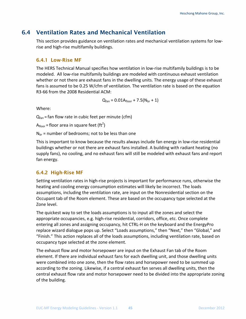
Heschong Mahone Group, Inc.
EUC‐MF Energy Modeling Guidelines ‐ Version 1.1 45 December 2012
6.4 Ventilation Rates and Mechanical Ventilation
This section provides guidance on ventilation rates and mechanical ventilation systems for low‐rise and high‐rise multifamily buildings.
6.4.1 Low-Rise MF
The HERS Technical Manual specifies how ventilation in low‐rise multifamily buildings is to be modeled. All low‐rise multifamily buildings are modeled with continuous exhaust ventilation whether or not there are exhaust fans in the dwelling units. The energy usage of these exhaust fans is assumed to be 0.25 W/cfm of ventilation. The ventilation rate is based on the equation R3‐66 from the 2008 Residential ACM:
Qfan = 0.01Afloor + 7.5(Nbr + 1)
Where:
Qfan = fan flow rate in cubic feet per minute (cfm)
Afloor = floor area in square feet (ft2)
Nbr = number of bedrooms; not to be less than one
This is important to know because the results always include fan energy in low‐rise residential buildings whether or not there are exhaust fans installed. A building with radiant heating (no supply fans), no cooling, and no exhaust fans will still be modeled with exhaust fans and report fan energy.
6.4.2 High-Rise MF
Setting ventilation rates in high‐rise projects is important for performance runs, otherwise the heating and cooling energy consumption estimates will likely be incorrect. The loads assumptions, including the ventilation rate, are input on the Nonresidential section on the Occupant tab of the Room element. These are based on the occupancy type selected at the Zone level.
The quickest way to set the loads assumptions is to input all the zones and select the appropriate occupancies, e.g. high‐rise residential, corridors, office, etc. Once complete entering all zones and assigning occupancy, hit CTRL‐H on the keyboard and the EnergyPro replace wizard dialogue pops up. Select “Loads assumptions,” then “Next,” then “Global,” and “Finish.” This action replaces all of the loads assumptions, including ventilation rate, based on occupancy type selected at the zone element.
The exhaust flow and motor horsepower are input on the Exhaust Fan tab of the Room element. If there are individual exhaust fans for each dwelling unit, and those dwelling units were combined into one zone, then the flow rates and horsepower need to be summed up according to the zoning. Likewise, if a central exhaust fan serves all dwelling units, then the central exhaust flow rate and motor horsepower need to be divided into the appropriate zoning of the building.
Heschong Mahone Group, Inc.
EUC‐MF Energy Modeling Guidelines ‐ Version 1.0 46 December 2012
7. ENERGY ANALYSIS AND ENERGY EFFICIENCY MEASURE ELIGIBILITY
Performing the existing building analysis and energy efficiency measure analysis in one energy modeling file is preferable to using separate energy models for the existing conditions and proposed conditions. Modeling all measures in one energy model file has several benefits including less quality control efforts and less potential for error of inputs. Using the Alternatives tab of EnergyPro is the easiest way to model the building and different energy efficiency measures. However, there are several types of measures that cannot currently be accounted for using the EnergyPro Alternatives tab, and a separate model will be required if the analyst is to claim energy savings for the measure.
7.1 Energy Analysis Using One EnergyPro File
CalRatePro report results as TDV energy, and includes cooling energy for all projects. If your project does not have cooling, and you are not using the ECON‐2 report with the RES Performance module, you will need to post‐process the cooling energy out of the results to show 10% improvement over existing conditions.
The following is a list of measures that can be modeled in the Alternatives tab, and are eligible for incentives through the EUC‐MF program:
Roof type and insulation Cool roof and radiant barrier Wall type and insulation Floor type and insulation Window performance values Building infiltration rate HVAC System type and performance values HVAC duct distribution type HVAC duct leakage HVAC duct insulation Appliances Indoor dwelling unit lighting type and control – if hard‐wired high‐efficacy Outdoor dwelling unit lighting type and control– if hard‐wired high‐efficacy DHW type and performance values DHW distribution insulation and pumping control Heating Boiler type and performance values
Though the following measures can be modeled in the EnergyPro Alternatives tab, they are not eligible upgrades in the EUC‐MF program: Solar savings fraction for DHW Renewable energy production Refrigerant charge verification System airflow verification
Heschong Mahone Group, Inc.
EUC‐MF Energy Modeling Guidelines ‐ Version 1.1 47 December 2012
System fan wattage verification Programmable set‐back thermostats CFL bulb installation
Measures that cannot be modeled in the Alternatives Tab, and are not eligible in the EUC‐MF program include, but are not limited to:
Removing heat lamps Removing hard‐wired fixtures so there are fewer hard‐wired fixtures in that room Low‐flow water fixtures Lighting not attached to building, e.g. parking lot lighting and landscape lighting HVAC and DHW equipment tune‐ups Removal (without replacement) of systems required by‐law in residential units (e.g.
space heating)
7.2 Using Multiple Energy Models
Some energy efficiency measures, or building upgrades, cannot be modeled with the ‘Alternatives tab and will require two models to complete the analysis. The steps to doing so are to first correctly model all existing (pre‐upgrade) conditions. Perform quality control on the existing building inputs and results to ensure accurate modeling has been accomplished. Next, make a copy of the pre‐retrofit model, save‐as a new file name, and proceed to make adjustments to the post‐retrofit energy model that captures the suggested energy efficiency measures.
It is suggested that during this analysis, when using the two model approach, an iterative process is used to analyze each measure by itself to ascertain individual measure savings and whether or not they should be recommended as a measure to the building owner. This also can facilitate quality control of results.
Submit the final existing pre‐retrofit and proposed post‐retrofit EnergyPro files to the program for assessment review.
The following measures require a two‐model approach:
Envelope
Change in window area Change in wall, roof, or floor area Change in overhang characteristics
Lighting and Appliances
Dwelling unit lighting and controls in high‐rise multifamily Common area lighting and controls in high‐rise multifamily Appliances in high‐rise multifamily
HVAC
Some system type changes involving hydronic heating that require the heating source to be chosen

Heschong Mahone Group, Inc.
EUC‐MF Energy Modeling Guidelines ‐ Version 1.0 48 December 2012
Any type of central cooling systems utilizing chillers, cooling towers, or ground source heat sinks
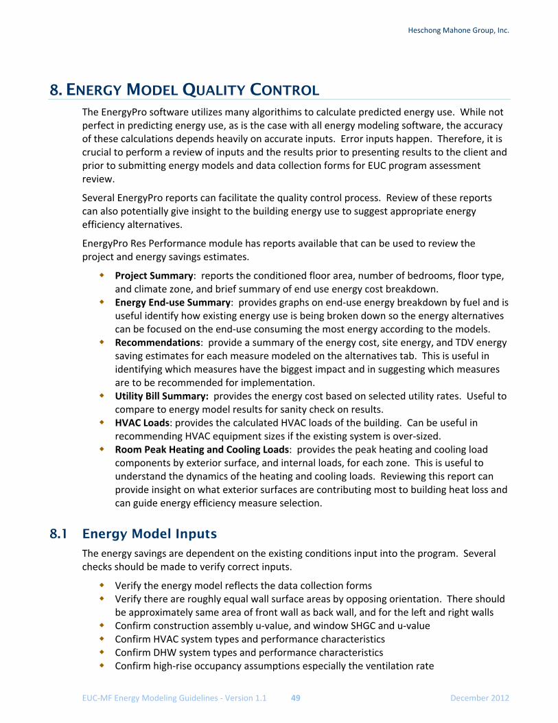
Heschong Mahone Group, Inc.
EUC‐MF Energy Modeling Guidelines ‐ Version 1.1 49 December 2012
8. ENERGY MODEL QUALITY CONTROL The EnergyPro software utilizes many algorithims to calculate predicted energy use. While not perfect in predicting energy use, as is the case with all energy modeling software, the accuracy of these calculations depends heavily on accurate inputs. Error inputs happen. Therefore, it is crucial to perform a review of inputs and the results prior to presenting results to the client and prior to submitting energy models and data collection forms for EUC program assessment review.
Several EnergyPro reports can facilitate the quality control process. Review of these reports can also potentially give insight to the building energy use to suggest appropriate energy efficiency alternatives.
EnergyPro Res Performance module has reports available that can be used to review the project and energy savings estimates.
Project Summary: reports the conditioned floor area, number of bedrooms, floor type, and climate zone, and brief summary of end use energy cost breakdown.
Energy End‐use Summary: provides graphs on end‐use energy breakdown by fuel and is useful identify how existing energy use is being broken down so the energy alternatives can be focused on the end‐use consuming the most energy according to the models.
Recommendations: provide a summary of the energy cost, site energy, and TDV energy saving estimates for each measure modeled on the alternatives tab. This is useful in identifying which measures have the biggest impact and in suggesting which measures are to be recommended for implementation.
Utility Bill Summary: provides the energy cost based on selected utility rates. Useful to compare to energy model results for sanity check on results.
HVAC Loads: provides the calculated HVAC loads of the building. Can be useful in recommending HVAC equipment sizes if the existing system is over‐sized.
Room Peak Heating and Cooling Loads: provides the peak heating and cooling load components by exterior surface, and internal loads, for each zone. This is useful to understand the dynamics of the heating and cooling loads. Reviewing this report can provide insight on what exterior surfaces are contributing most to building heat loss and can guide energy efficiency measure selection.
8.1 Energy Model Inputs
The energy savings are dependent on the existing conditions input into the program. Several checks should be made to verify correct inputs.
Verify the energy model reflects the data collection forms Verify there are roughly equal wall surface areas by opposing orientation. There should
be approximately same area of front wall as back wall, and for the left and right walls Confirm construction assembly u‐value, and window SHGC and u‐value Confirm HVAC system types and performance characteristics Confirm DHW system types and performance characteristics Confirm high‐rise occupancy assumptions especially the ventilation rate
Heschong Mahone Group, Inc.
EUC‐MF Energy Modeling Guidelines ‐ Version 1.0 50 December 2012
8.2 Reasonableness of Results
Reviewing results should include at least the following checks.
For the existing pre‐retrofit model, do the energy use estimates appear reasonable by end‐use and for the selected climate zone? Compare the heating and cooling energy estimates to the heating and cooling degree day numbers for the climate zone the building is modeled in.
For each of the energy efficiency measures, can the savings be justified based on rules‐of‐thumb, the number of operating hours, and the indoor and outdoor temperature conditions for the building?
Does the package of energy efficiency measures have energy efficiency savings equal to, worse than, or better than the sum of the savings for the energy efficiency measures (generally the interaction between savings will result in a cumulative savings that is less than the sum of the savings). Can the cumulative impact of the energy efficiency measures be justified?