Determination of the ballast water exchange sequence for ...
7
Zeszyty Naukowe 25(97) 21 Scientific Journals Zeszyty Naukowe Maritime University of Szczecin Akademia Morska w Szczecinie 2011, 25(97) pp. 21–27 2011, 25(97) s. 21–27 Determination of the ballast water exchange sequence for an LNG carrier using a liquid cargo handling simulator Wyznaczanie sekwencji wymiany wód balastowych gazowca LNG z wykorzystaniem symulatora ładunkowego statków do przewozu ładunków ciekłych Paweł Chorab Maritime University of Szczecin, Faculty of Navigation, Institut of Marine Navigation Akademia Morska w Szczecinie, Wydział Nawigacyjny, Instytut Nawigacji Morskiej 70-500 Szczecin, ul. Wały Chrobrego 1–2, e-mail: [email protected] Key words: ballast, ballast water exchange, LNG carrier, LNG simulator Abstract The sequential method of emptying and filling of ballast tanks at sea may pose extra threats for ship’s safety. The prepared Ballast Water Management (BWM) Plan enables carrying out the operation so that negative effects of emptying each ballast tank are minimized. A large number of tanks and substantial volume of ballast water to be exchanged may create difficulties in preparing an optimized plan. The author proposes to use a liquid cargo handling simulator for the preparation of the BWM plan for selected LNG carriers. Słowa kluczowe: balast, wymiana wód balastowych, gazowiec LNG, symulator LNG Abstrakt W czasie opróżniania i napełniania zbiorników balastowych w morzu metodą sekwencyjną mogą pojawić się dodatkowe zagrożenia dotyczące bezpieczeństwa statku. Przygotowany wcześniej Plan Wymiany Wód Bala- stowych pozwala tak przeprowadzić operację, aby minimalizować negatywne skutki opróżniania zbiorników balastowych. Ich duża liczba i znaczna objętość wody balastowej może utrudniać przygotowani e optymalne- go planu wymiany. Zaproponowano wykorzystanie symulatora ładunkowego do przewozu ładunków ci e- kłych w przygotowaniu takiego planu dla wybranych gazowców. Introduction The ship in operation happens to sail under bal- last. Such situations occur when the ship has no cargo or is partly loaded, and the ballast water pumped into tanks is aimed at ensuring ship safety in terms of stability. As the vessel is discharged in the port of destination, it pumps in the amount of ballast water necessary for safe voyage. When new cargo is being loaded, ballast water is pumped out into the sea. In this way the quantity of seawater carried by ships under ballast annually amounts to as much as 10 billion tons [1, 2]. The exchange of ballast water between ports is connected with the transfer of living organisms, including micro- organisms and bacteria in ballast waters between various regions of the world. When ballast water is discharged, these organisms often disturb the eco- logical balance in the natural environment of a re- gion. To partly limit this problem the exchange of ballast waters in open ocean has been enforced. Obviously, such exchange should be performed in a manner avoiding any risks for ship safety. On 13 February 2004 the International Maritime Organization adopted the International Convention for the Control and Management of Ships’ Ballast Water and Sediments (BWM). Additionally, each ship should carry and use Ballast Water Manage- ment Plan. Such plan should be approved by the administration and take into account guidelines set
Transcript of Determination of the ballast water exchange sequence for ...
Zeszyty Naukowe 25(97) 21
Scientific Journals Zeszyty Naukowe Maritime University of Szczecin Akademia Morska w Szczecinie
2011, 25(97) pp. 21–27 2011, 25(97) s. 21–27
Determination of the ballast water exchange sequence for an LNG carrier using a liquid cargo handling simulator
Wyznaczanie sekwencji wymiany wód balastowych gazowca LNG z wykorzystaniem symulatora ładunkowego statków do przewozu ładunków ciekłych
Paweł Chorab
Maritime University of Szczecin, Faculty of Navigation, Institut of Marine Navigation Akademia Morska w Szczecinie, Wydział Nawigacyjny, Instytut Nawigacji Morskiej 70-500 Szczecin, ul. Wały Chrobrego 1–2, e-mail: [email protected]
Key words: ballast, ballast water exchange, LNG carrier, LNG simulator
Abstract The sequential method of emptying and filling of ballast tanks at sea may pose extra threats for ship’s safety.
The prepared Ballast Water Management (BWM) Plan enables carrying out the operation so that negative
effects of emptying each ballast tank are minimized. A large number of tanks and substantial volume of
ballast water to be exchanged may create difficulties in preparing an optimized plan. The author proposes to
use a liquid cargo handling simulator for the preparation of the BWM plan for selected LNG carriers.
Słowa kluczowe: balast, wymiana wód balastowych, gazowiec LNG, symulator LNG
Abstrakt W czasie opróżniania i napełniania zbiorników balastowych w morzu metodą sekwencyjną mogą pojawić się
dodatkowe zagrożenia dotyczące bezpieczeństwa statku. Przygotowany wcześniej Plan Wymiany Wód Bala-
stowych pozwala tak przeprowadzić operację, aby minimalizować negatywne skutki opróżniania zbiorników
balastowych. Ich duża liczba i znaczna objętość wody balastowej może utrudniać przygotowanie optymalne-
go planu wymiany. Zaproponowano wykorzystanie symulatora ładunkowego do przewozu ładunków cie-
kłych w przygotowaniu takiego planu dla wybranych gazowców.
Introduction
The ship in operation happens to sail under bal-
last. Such situations occur when the ship has no
cargo or is partly loaded, and the ballast water
pumped into tanks is aimed at ensuring ship safety
in terms of stability. As the vessel is discharged in
the port of destination, it pumps in the amount of
ballast water necessary for safe voyage. When new
cargo is being loaded, ballast water is pumped out
into the sea. In this way the quantity of seawater
carried by ships under ballast annually amounts to
as much as 10 billion tons [1, 2]. The exchange of
ballast water between ports is connected with the
transfer of living organisms, including micro-
organisms and bacteria in ballast waters between
various regions of the world. When ballast water is
discharged, these organisms often disturb the eco-
logical balance in the natural environment of a re-
gion. To partly limit this problem the exchange of
ballast waters in open ocean has been enforced.
Obviously, such exchange should be performed in
a manner avoiding any risks for ship safety.
On 13 February 2004 the International Maritime
Organization adopted the International Convention
for the Control and Management of Ships’ Ballast
Water and Sediments (BWM). Additionally, each
ship should carry and use Ballast Water Manage-
ment Plan. Such plan should be approved by the
administration and take into account guidelines set
Paweł Chorab
22 Scientific Journals 25(97)
forth by the IMO. The plan should include, but not
be limited to: detailed safety procedures for the ship
and personnel connected with ballast water man-
agement as required by the Convention, detailed
description of actions to be taken to implement the
ballast water management requirements and sup-
plemental ballast water management practices pro-
vided by the Convention.
Each ship trading internationally should carry
a Ballast Water Record Book. This record book is
a document that should contain information on each
discharge, exchange, or pumping in of ballast wa-
ter, position of the operation, water salinity, initial
and final volumes in the tanks, pumps used, area
depth. This information constitutes evidence that
the BWM is observed and can be controlled by
competent authority. The Convention also provides
how and where ballast waters should be exchanged.
Besides, the Convention stipulates that relevant
national regulations, even if in more detail address
ballast water issues, they should not be in contra-
diction to the BWM provisions.
Sequential method of ballast water exchange
The ship that exchanges ballast waters in order
to observe technical standards contained in regula-
tions of the Convention should, whenever possible,
do so in an area at least 200 nautical miles away
from the nearest land, in waters of at least 200 me-
tres in depth, taking into consideration the guide-
lines set forth by the IMO [3].
There are three basic methods of ballast water
exchange:
Sequential method: ballast tanks are emptied
and then filled with replacement ballast water,
one or more at a time,
Flow-through method: ballast tanks are refilled
with replacement ballast water that pushes out
in-port or near-shore water,
Dilution method: replacement ballast water is
filled through the top of the ballast tank with si-
multaneous discharge from the bottom at the
same flow rate and maintaining a constant level
in the tank.
The first of the methods described is the most
commonly used in ships. The fastest and least ener-
gy-consuming, the sequential method does not re-
quire additional technical solutions in the existing
ballast installations. Discharging and refilling of
tanks, however, temporarily decreases ship’s stabil-
ity and other safety-related properties. In the se-
quential method, particular operations make up
a specific sequence, an order in which discharge
and refilling of each tank take place. The sequential
method is used when the exchange of ballast is
connected with the removal of a very large quantity
of water while the ship is en route and refilling the
tanks with replacement ballast water in the open
ocean. This is a new procedure, different from the
method of ballasting in the port, because at sea the
ship is exposed to more risks, particularly the influ-
ence of wind and waves.
Methods of establishing the sequence of ballast tank emptying and refilling
The method of sequential discharges and refills
is quite commonly used by ships, contrary to the
flow-through method. The reason is that existing
ballast installations are not adjusted to, inter alia,
excessive pressures when replacement water is
pumped in. In the sequential method each operation
is part of the sequence of actions planned for an
individual tank. While establishing the sequence of
ballast water exchange, the following procedure is
used. Ship’s operational data are first determined:
trim, drafts forward and aft, shear forces and bend-
ing moments of the hull. The calculations are con-
ducted in the process of discharge and refilling of
subsequent tanks. Thus calculated values are com-
pared with criterial values, and procedure is re-
peated for each tank in turn. This manner of safety
assessment refers only to ship’s parameters in calm
water. Besides, the application of the same proce-
dure for each ship, regardless of its type and vary-
ing ballast installation characteristics, is a simplifi-
cation and not fully satisfactory.
According to the Convention [3], the sequence
of ballast water exchange should be demonstrated
at least for typical loading conditions taken from
the approved Stability Information. The ballast
water exchange sequence should be divided into
steps, with the following data specified in each
step:
water volume in each tank,
pumps used,
approximate time of operation,
longitudinal strength as a function of allowable
values,
stability information taking into account free
liquid surfaces during discharge or refilling,
draft values at fore and aft perpendiculars,
other information.
It is recommended that return to the initial con-
dition should be possible after each step. The deci-
sion to continue an operation should be taken after
making sure that the predicted ship’s position does
not differ from the actual one, weather forecast is
Determination of the ballast water exchange sequence for an LNG carrier using a liquid cargo handling simulator
Zeszyty Naukowe 25(97) 23
favourable, capacity of ballast water equipment has
not decreased and the number of personnel in-
volved remains the same. If any of these factors is
not as required, the ballast water exchange should
be stopped or completely given up. Ship’s listing,
caused by unsymmetrical emptying and refilling of
ballast tanks has to be taken into consideration so
that each step takes place when the ship is in
upright position (no list). The conducted operations
have to be monitored in order not to generate lists
during pumping. The steps have to take into ac-
count the assumed trim and draft requirements,
avoid slamming, ensure that the propeller is sub-
merged and that loss of vision from the bridge is
minimal.
It is very important to avoid vacuum during
stripping or overpressure while refilling a tank. The
exchange sequence may be different for various
ship types and different loading states – ship’s safe-
ty should be the basic criterion. Emptying more
than one ballast tanks on one side is avoided as this
creates a risk of capsizing. Two adjacent tanks must
not be pumped out at the same time due to large
shear forces and bending moments. The ballast
exchange sequence is established in compliance
with the regulations and restrictions in force. The
sequential method for each ship is prepared in the
form of a Ballast Water Management (BWM) Plan.
The plan is worked out specifically for a vessel and
approved by a classification society.
Risks to ship safety during ballast water exchange
From the viewpoint of ship stability-related
safety the process of water exchange will be dan-
gerous; in addition, risk will become greater in
adverse weather conditions. The types of risk that
occur during ballast water exchange at sea may
vary for various ship types, as underlined in, inter
alia, [4] and [5]. Analyses found in a number of
publications indicate the major causes of risk:
too long time of ballast water exchange,
incorrect sequence of tank emptying and refil-
ling,
inadequate operational parametric values during
the exchange,
adverse weather conditions (wind, high seas).
Of various operational threats, the most danger-
ous are considered to be:
loss or significant deterioration of stability,
increased ship motions, rolling in particular,
emergence of the propeller at too low aft draft,
which leads to worse propulsion and manoeuvr-
ing ability,
bow emergence, which results in slamming and
worsened visibility from the navigational bridge
(blind sector ahead of the ship).
If threats arising during ballast water exchange
are not to decrease ship operating safety below an
acceptable level, each step of the exchange se-
quence should comply with mandatory regulations
and stability criteria [6]. These requirements may
vary for various ship types and sizes. In practice,
particularly in bad weather, some requirements are
not met.
The studies [4, 5] analyze the process of empty-
ing subsequent tanks and its influence on conse-
quent changes in ship parameters, but they do not
evaluate the impact of weather conditions. In their
conclusions, however, the authors draw attention to
the need for more comprehensive analysis of ship
safety during ballast exchange by taking into con-
sideration the effect of wave action and ship mo-
tions. Unfortunately, such studies have not been
available yet. Shipowners developing Ballast Water
Management Plans for ships in service do not ac-
count for weather conditions either, and the safety
limits for the exchange are set after a subjective
evaluation of the ship’s master.
The following conclusions can be drawn from
analyses of worldwide literature on procedures amd
methods of ballast water exchange, research into
ship safety related with such exchange and actual
measurements conducted on ships in operation:
there is insufficient research on stability-related
safety of a ship exchanging ballast water,
existing data do not account for the influence of
real weather conditions on ship safety during
ballast water exchange,
no data are available on the evaluation of
changes in ship motions during the emptying
and refilling of ballast tanks,
phenomena of slamming and propeller emer-
gence during ballast exchange in waves have not
been analyzed,
no analysis has been made in reference to the
extent to which alteration of course and/or speed
will improve ship safety during the emptying
and refilling of ballast tanks in bad weather.
From critical analysis of the procedures used
and the existing knowledge on ship safety during
ballast water exchange and operational demands
reported by shipowners, the following research
problems can be formulated:
determine the relations between ship’s speed
and course and weather parameters versus ship
safety level during ballast water exchange,
Paweł Chorab
24 Scientific Journals 25(97)
determine the probability of ship safety risk and
its duration during ballast exchange in specific
weather conditions,
define possibilities of reducing the risks by alter-
ing ship’s course and/or speed, or possibly the
change in the sequence and number of simulta-
neously emptied and refilled ballast tanks,
search for an optimal sequence of emptying and
refilling in given operational conditions (ship’s
speed and course, weather conditions),
determine an optimal quantity of ballast water
(including the number of tanks and their loca-
tion) needed to ensure ship safety in a given op-
erational situation.
Liquid cargo handling simulator
One of the modules of a Liquid Cargo Handling
Simulator is the ballast module referred to as Bal-
last control system – Line and valves. The inclusion
of this module in the simulator equipment puts its
software in compliance with IMO model courses
for tankers: IMO 1.35 LPG Tanker Cargo & Bal-
last Handling, IMO 1.36 LNG Tanker Cargo &
Ballast Handling, IMO 1.35 Chemical Tanker Car-
go & Ballast Handling.
Two examples of ships with essential informa-
tion on the simulation of ballast installation opera-
tion on LNG carriers are given in table 1.
Table 1. Main particulars of selected LNG-s and LNG-m
carriers [7]
Tabela 1. Dane techniczne przykładowych gazowców typu
LNG-s, LNG-m [7]
LNG-s LNG-m
Deadweight capacity DWT [t] 67 900 62 700
Length overall Loa [m] 290 275
Length between perps Lbp [m] 275 260
Breadth B [m] 48.1 43.4
Moulded depth H [m] 27 26
Moulded draft T [m] 11.7 11.95
Volume of cargo tanks VH [m3] 135 000 130 000
Volume of ballast tanks VB [m3] 63 000 46 000
LNG-m – LNG carrier with membrane takns
LNG-s – LNG carrier with spherical tanks
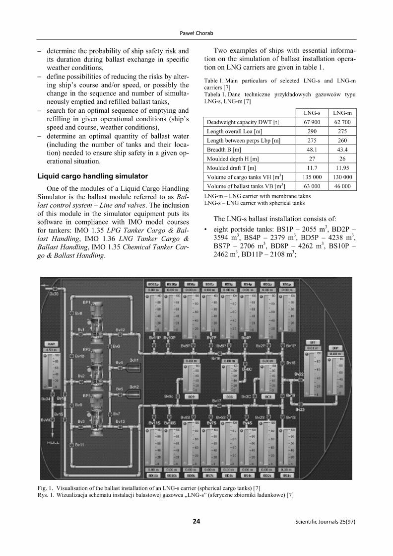
The LNG-s ballast installation consists of:
• eight portside tanks: BS1P – 2055 m3, BD2P –
3594 m3, BS4P – 2379 m
3, BD5P – 4238 m
3,
BS7P – 2706 m3, BD8P – 4262 m
3, BS10P –
2462 m3, BD11P – 2108 m
3;
Fig. 1. Visualisation of the ballast installation of an LNG-s carrier (spherical cargo tanks) [7]
Rys. 1. Wizualizacja schematu instalacji balastowej gazowca „LNG-s” (sferyczne zbiorniki ładunkowe) [7]
Determination of the ballast water exchange sequence for an LNG carrier using a liquid cargo handling simulator
Zeszyty Naukowe 25(97) 25
• eight starboard tanks: BS1S – 2055 m3, BD2S –
3594 m3, BS4S – 2379 m
3, BD5S – 4238 m
3,
BS7S – 2706 m3, BD8S – 4262 m
3, BS10S –
2462 m3, BD11S – 2108 m
3;
• three central tanks: BC3 – 1500 m3, BC6 –
1500 m3, BC9 – 1500 m
3;
• two forepeak tanks: BFP – 7782 m3, BFT –
1500 m3 (void space);
• afterpeak tank: BAP – 3110 m3;
• throttling valves for communication between
ballast tanks and ballast lines, as shown in
figure 1;
• centrifugal BP pumps; the pumps have identical
characteristics and provide charging pressure of
~2.8 bar at a flow of ~2,800 m3/h);
• three sea chests Bch1, Bch2 with strainers;
• throttling valves on the charging line of each
pump: Bv1, Bv2,Bv3;
• cut-off valves: BV4… BV19;
• non-return valve Bv20.
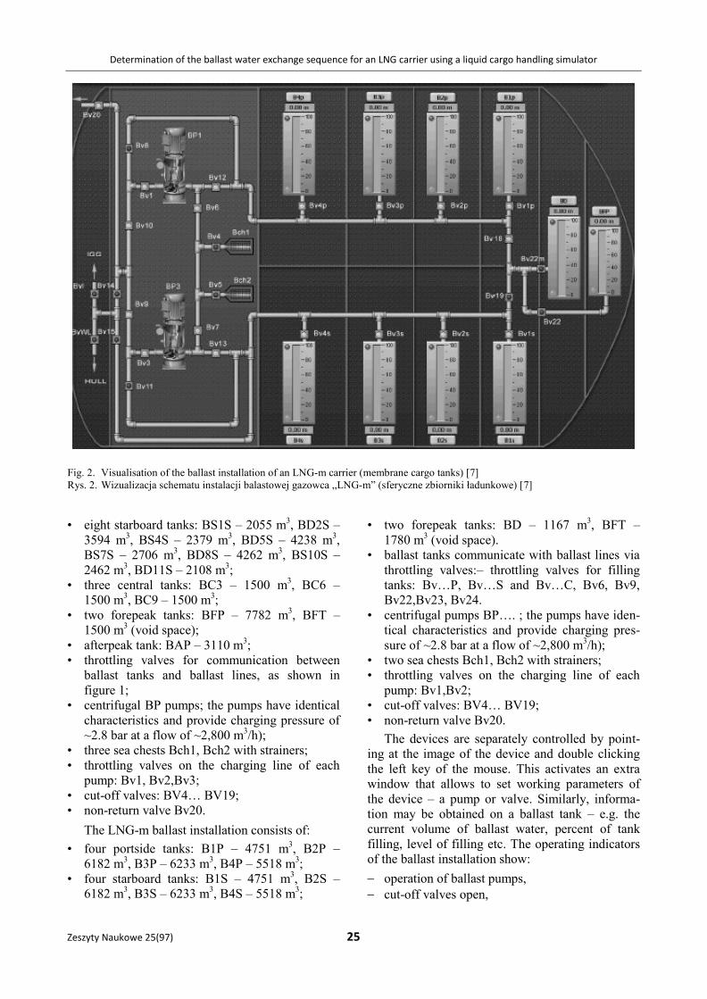
The LNG-m ballast installation consists of:
• four portside tanks: B1P – 4751 m3, B2P –
6182 m3, B3P – 6233 m
3, B4P – 5518 m
3;
• four starboard tanks: B1S – 4751 m3, B2S –
6182 m3, B3S – 6233 m
3, B4S – 5518 m
3;
• two forepeak tanks: BD – 1167 m3, BFT –
1780 m3 (void space).
• ballast tanks communicate with ballast lines via
throttling valves:– throttling valves for filling
tanks: Bv…P, Bv…S and Bv…C, Bv6, Bv9,
Bv22,Bv23, Bv24.
• centrifugal pumps BP…. ; the pumps have iden-
tical characteristics and provide charging pres-
sure of ~2.8 bar at a flow of ~2,800 m3/h);
• two sea chests Bch1, Bch2 with strainers;
• throttling valves on the charging line of each
pump: Bv1,Bv2;
• cut-off valves: BV4… BV19;
• non-return valve Bv20.
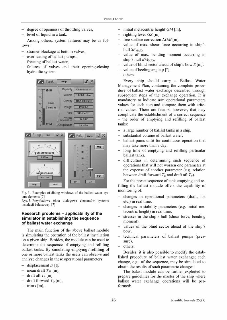
The devices are separately controlled by point-
ing at the image of the device and double clicking
the left key of the mouse. This activates an extra
window that allows to set working parameters of
the device – a pump or valve. Similarly, informa-
tion may be obtained on a ballast tank – e.g. the
current volume of ballast water, percent of tank
filling, level of filling etc. The operating indicators
of the ballast installation show:
operation of ballast pumps,
cut-off valves open,
Fig. 2. Visualisation of the ballast installation of an LNG-m carrier (membrane cargo tanks) [7]
Rys. 2. Wizualizacja schematu instalacji balastowej gazowca „LNG-m” (sferyczne zbiorniki ładunkowe) [7]
Paweł Chorab
26 Scientific Journals 25(97)
degree of openness of throttling valves,
level of liquid in a tank.
Among others, system failures may be as fol-
lows:
strainer blockage at bottom valves,
overheating of ballast pumps,
freezing of ballast water,
failures of valves and their opening-closing
hydraulic system.
Fig. 3. Examples of dialog windows of the ballast water sys-
tem elements [7]
Rys. 3. Przykładowe okna dialogowe elementów systemu
instalacji balastowej. [7]
Research problems – applicability of the simulator in establishing the sequence of ballast water exchange
The main function of the above ballast module
is simulating the operation of the ballast installation
on a given ship. Besides, the module can be used to
determine the sequence of emptying and refilling
ballast tanks. By simulating emptying / refilling of
one or more ballast tanks the users can observe and
analyze changes in these operational parameters:
displacement D [t],
mean draft TŚR [m],
draft aft TR [m],
draft forward TD [m],
trim t [m],
initial metacentric height GM [m],
righting lever GZ [m]
free surface correction ΔGM [m],
value of max. shear force occurring in ship’s
hull SFMAX,
value of max. bending moment occurring in
ship’s hull BMMAX,
value of blind sector ahead of ship’s bow S [m],
value of heeling angle φ [],
others.
Every ship should carry a Ballast Water
Management Plan, containing the complete proce-
dure of ballast water exchange described through
subsequent steps of the exchange operation. It is
mandatory to indicate a/m operational parameters
values for each step and compare them with crite-
rial values. There are factors, however, that may
complicate the establishment of a correct sequence
– the order of emptying and refilling of ballast
tanks:
a large number of ballast tanks in a ship,
substantial volume of ballast water,
ballast pums unfit for continuous operation that
may take more than a day,
long time of emptying and refilling particular
ballast tanks,
difficulties in determining such sequence of
operations that will not worsen one parameter at
the expense of another parameter (e.g. relation
between draft forward TD and draft aft TR).
For the preset sequence of tank emptying and re-
filling the ballast module offers the capability of
monitoring of:
changes in operational parameters (draft, list
etc.) in real time,
changes in stability parameters (e.g. initial me-
tacentric height) in real time,
stresses in the ship’s hull (shear force, bending
moment),
values of the blind sector ahead of the ship’s
bow,
technical parameters of ballast pumps (pres-
sure),
others.
Besides, it is also possible to modify the estab-
lished procedure of ballast water exchange; each
change, e.g., of the sequence, may be simulated to
obtain the results of such parametric changes.
The balast module can be further exploited to
prepare guidelines for the master of the ship where
ballast water exchange operations will be per-
formed:
Determination of the ballast water exchange sequence for an LNG carrier using a liquid cargo handling simulator
Zeszyty Naukowe 25(97) 27
scenario with many steps, with small changes in
operational parameters, suitable for use in severe
weather conditions,
scenario with few steps, causing relatively large
changes in operational parameters, suitable for
use in good weather,
emergency scenarios, e.g. failure of one ballast
pump, failure of any valve,
most adverse and most dangerous emergency
scenarios, where a failure occurs to the most im-
portant component of the ballast installation
from ship’s safety viewpoint,
others.
It should be underlined that simulation is in real
time (there is an option of time compression),
which enables constant preview of each of the
above mentioned parameters, which is rare in pre-
sently used Ballast Water Management Plans. Be-
sides, it should be mentioned that currently imple-
mented plans comprise only one, not necesserily
optimal solution for the subsequent emptying and
refilling of tanks in the method herein described. A
possible failure of any element of the ballast instal-
lation brings about temporary solutions, not sup-
ported by tips or instructions as such do not exist in
plans developed to date.
Conclusions
The use of a Liquid Cargo Handling Simulator
with its ballast module: Ballast control system –
Line and valves in the development of a ballast
water exchange plan will:
facilitate the process of determining the order in
which ballast tanks should be emptied and re-
filled,
enable the establishment of optimal sequence
of ballast water exchange,
enable preparing emergency scenarios with
a failure of any element of the ballast installa-
tion,
allow to present, in real time, changes in opera-
tional parameters of the ship during the empty-
ing and refilling of ballast tanks.
The development of such comprehensive analy-
sis of the ballast water exchange by the sequential
method will significantly facilitate a further analy-
sis based on the BWM Plan, concerning the influ-
ence of actual weather conditions and alteration of
ship’s course and/or speed on the ship’s safety dur-
ing that complicated process.
References
1. http://globallast.imo.org/
2. http://www.imo.org/Pages/home.aspx
3. IMO, Międzynarodowa Konwencja o kontroli i postępo-
waniu ze statkowymi wodami balastowymi i osadami,
2004 (Konwencja BWM 2004). Wydanie PRS, 2006.
4. AKIYAMA A., UETSUHARA F., SAGISHIMA Y.: Ballast Water
Exchange Procedures and their Problems. Transactions of
the West-Japan Society of Naval Architects, 2000, 100,
41–53, www.sciencedirect.com
5. BIELAŃSKI J.: Considerations about the guidelines on safety
of ballast water exchange at sea. Hydronav’99 – Maneuver-
ing ’99, Joint 13th International Conference on Hydrody-
namics in Ship Design and 2nd International Symposium on
Ship Maneuvering, Gdańsk–Ostróda 1999.
6. IMO, International Code of Intact Stability, Edition 2009,
London 2008.
7. http://www.transas.com/products/simulators/
Recenzent:
dr hab. Leszek Smolarek prof. AM
Akademia Morska w Gdyni